US11013913B2 - Kits and methods for securing a burr hole plugs for stimulation systems - Google Patents
Kits and methods for securing a burr hole plugs for stimulation systemsDownload PDFInfo
- Publication number
- US11013913B2 US11013913B2US16/351,350US201916351350AUS11013913B2US 11013913 B2US11013913 B2US 11013913B2US 201916351350 AUS201916351350 AUS 201916351350AUS 11013913 B2US11013913 B2US 11013913B2
- Authority
- US
- United States
- Prior art keywords
- guide
- base
- burr hole
- kit
- hole plug
- Prior art date
- Legal status (The legal status is an assumption and is not a legal conclusion. Google has not performed a legal analysis and makes no representation as to the accuracy of the status listed.)
- Expired - Fee Related, expires
Links
Images


Classifications
- A—HUMAN NECESSITIES
- A61—MEDICAL OR VETERINARY SCIENCE; HYGIENE
- A61N—ELECTROTHERAPY; MAGNETOTHERAPY; RADIATION THERAPY; ULTRASOUND THERAPY
- A61N1/00—Electrotherapy; Circuits therefor
- A61N1/02—Details
- A61N1/04—Electrodes
- A61N1/05—Electrodes for implantation or insertion into the body, e.g. heart electrode
- A61N1/0526—Head electrodes
- A61N1/0529—Electrodes for brain stimulation
- A61N1/0539—Anchoring of brain electrode systems, e.g. within burr hole
- A—HUMAN NECESSITIES
- A61—MEDICAL OR VETERINARY SCIENCE; HYGIENE
- A61B—DIAGNOSIS; SURGERY; IDENTIFICATION
- A61B17/00—Surgical instruments, devices or methods
- A61B17/16—Instruments for performing osteoclasis; Drills or chisels for bones; Trepans
- A61B17/1613—Component parts
- A61B17/1615—Drill bits, i.e. rotating tools extending from a handpiece to contact the worked material
- A—HUMAN NECESSITIES
- A61—MEDICAL OR VETERINARY SCIENCE; HYGIENE
- A61B—DIAGNOSIS; SURGERY; IDENTIFICATION
- A61B17/00—Surgical instruments, devices or methods
- A61B17/16—Instruments for performing osteoclasis; Drills or chisels for bones; Trepans
- A61B17/17—Guides or aligning means for drills, mills, pins or wires
- A61B17/1739—Guides or aligning means for drills, mills, pins or wires specially adapted for particular parts of the body
- A—HUMAN NECESSITIES
- A61—MEDICAL OR VETERINARY SCIENCE; HYGIENE
- A61B—DIAGNOSIS; SURGERY; IDENTIFICATION
- A61B90/00—Instruments, implements or accessories specially adapted for surgery or diagnosis and not covered by any of the groups A61B1/00 - A61B50/00, e.g. for luxation treatment or for protecting wound edges
- A61B90/10—Instruments, implements or accessories specially adapted for surgery or diagnosis and not covered by any of the groups A61B1/00 - A61B50/00, e.g. for luxation treatment or for protecting wound edges for stereotaxic surgery, e.g. frame-based stereotaxis
- A61B90/11—Instruments, implements or accessories specially adapted for surgery or diagnosis and not covered by any of the groups A61B1/00 - A61B50/00, e.g. for luxation treatment or for protecting wound edges for stereotaxic surgery, e.g. frame-based stereotaxis with guides for needles or instruments, e.g. arcuate slides or ball joints
- A—HUMAN NECESSITIES
- A61—MEDICAL OR VETERINARY SCIENCE; HYGIENE
- A61B—DIAGNOSIS; SURGERY; IDENTIFICATION
- A61B90/00—Instruments, implements or accessories specially adapted for surgery or diagnosis and not covered by any of the groups A61B1/00 - A61B50/00, e.g. for luxation treatment or for protecting wound edges
- A61B90/10—Instruments, implements or accessories specially adapted for surgery or diagnosis and not covered by any of the groups A61B1/00 - A61B50/00, e.g. for luxation treatment or for protecting wound edges for stereotaxic surgery, e.g. frame-based stereotaxis
- A61B2090/103—Cranial plugs for access to brain
- A—HUMAN NECESSITIES
- A61—MEDICAL OR VETERINARY SCIENCE; HYGIENE
- A61B—DIAGNOSIS; SURGERY; IDENTIFICATION
- A61B5/00—Measuring for diagnostic purposes; Identification of persons
- A61B5/68—Arrangements of detecting, measuring or recording means, e.g. sensors, in relation to patient
- A61B5/6846—Arrangements of detecting, measuring or recording means, e.g. sensors, in relation to patient specially adapted to be brought in contact with an internal body part, i.e. invasive
- A61B5/6847—Arrangements of detecting, measuring or recording means, e.g. sensors, in relation to patient specially adapted to be brought in contact with an internal body part, i.e. invasive mounted on an invasive device
- A61B5/6864—Burr holes
- A—HUMAN NECESSITIES
- A61—MEDICAL OR VETERINARY SCIENCE; HYGIENE
- A61F—FILTERS IMPLANTABLE INTO BLOOD VESSELS; PROSTHESES; DEVICES PROVIDING PATENCY TO, OR PREVENTING COLLAPSING OF, TUBULAR STRUCTURES OF THE BODY, e.g. STENTS; ORTHOPAEDIC, NURSING OR CONTRACEPTIVE DEVICES; FOMENTATION; TREATMENT OR PROTECTION OF EYES OR EARS; BANDAGES, DRESSINGS OR ABSORBENT PADS; FIRST-AID KITS
- A61F2/00—Filters implantable into blood vessels; Prostheses, i.e. artificial substitutes or replacements for parts of the body; Appliances for connecting them with the body; Devices providing patency to, or preventing collapsing of, tubular structures of the body, e.g. stents
- A61F2/02—Prostheses implantable into the body
- A61F2/28—Bones
- A61F2/2875—Skull or cranium
- A—HUMAN NECESSITIES
- A61—MEDICAL OR VETERINARY SCIENCE; HYGIENE
- A61N—ELECTROTHERAPY; MAGNETOTHERAPY; RADIATION THERAPY; ULTRASOUND THERAPY
- A61N1/00—Electrotherapy; Circuits therefor
- A61N1/02—Details
- A61N1/04—Electrodes
- A61N1/05—Electrodes for implantation or insertion into the body, e.g. heart electrode
- A61N1/0526—Head electrodes
- A61N1/0529—Electrodes for brain stimulation
- A61N1/0534—Electrodes for deep brain stimulation
- A—HUMAN NECESSITIES
- A61—MEDICAL OR VETERINARY SCIENCE; HYGIENE
- A61N—ELECTROTHERAPY; MAGNETOTHERAPY; RADIATION THERAPY; ULTRASOUND THERAPY
- A61N1/00—Electrotherapy; Circuits therefor
- A61N1/18—Applying electric currents by contact electrodes
- A61N1/32—Applying electric currents by contact electrodes alternating or intermittent currents
- A61N1/36—Applying electric currents by contact electrodes alternating or intermittent currents for stimulation
- A61N1/3605—Implantable neurostimulators for stimulating central or peripheral nerve system
- A—HUMAN NECESSITIES
- A61—MEDICAL OR VETERINARY SCIENCE; HYGIENE
- A61N—ELECTROTHERAPY; MAGNETOTHERAPY; RADIATION THERAPY; ULTRASOUND THERAPY
- A61N1/00—Electrotherapy; Circuits therefor
- A61N1/18—Applying electric currents by contact electrodes
- A61N1/32—Applying electric currents by contact electrodes alternating or intermittent currents
- A61N1/36—Applying electric currents by contact electrodes alternating or intermittent currents for stimulation
- A61N1/372—Arrangements in connection with the implantation of stimulators
- A61N1/375—Constructional arrangements, e.g. casings
Definitions
- the present disclosureis directed to the area of burr hole plugs and kits and methods for securing burr hole plugs.
- the present disclosureis also directed to implantable electrical stimulation systems including the kits for securing burr hole plugs, as well as methods of making and using the kits, burr hole plugs, and electrical stimulation systems.
- Implantable electrical stimulation systemshave proven therapeutic in a variety of diseases and disorders.
- stimulation of the brainsuch as deep brain stimulation
- spinal cord stimulation systemshave been used as a therapeutic modality for the treatment of chronic pain syndromes.
- Peripheral nerve stimulationhas been used to treat incontinence, as well as a number of other applications under investigation.
- Functional electrical stimulation systemshave been applied to restore some functionality to paralyzed extremities in spinal cord injury patients.
- a stimulatorcan include a control module (with a pulse generator), one or more leads, and an array of stimulator electrodes on each lead.
- the stimulator electrodesare in contact with or near the brain, nerves, or other tissue to be stimulated.
- the pulse generator in the control modulegenerates electrical pulses that are delivered by the electrodes to body tissue.
- a kit or arrangement for securing a burr hole plugincludes a guide base including an upper flange, a lower flange, and a connecting member coupling the upper flange to the lower flange, each of the upper flange and the lower flange defining one or more guide holes, wherein the one or more guide holes of the upper flange are aligned with the one or more guide holes of the lower flange; a drill shank coupleable to a drill and including a cutting element and a main shaft that are configured to pass through any one of the one or more guide holes in the upper flange of the guide base; and one or more guide collets including a collet shaft and a fastener tube extending from the collet shaft to receive a fastener, where the collet shaft and fastener tube are configured for insertion into any one of the one or more guide holes in the upper flange of the guide base.
- each of the upper flange and the lower flangedefines at least two of the guide holes.
- the shaft of the drill shankhas an outer diameter that is greater than an inner diameter of any one of the one or more guide holes in the lower flange of the guide base.
- each of the one or more guide holes in the lower flangehas a diameter that decreases toward a bottom of the lower flange, where the shaft of the drill shank has an outer diameter that is greater than an inner diameter of at least a portion of any one of the one or more guide holes in the lower flange of the guide base.
- the guide colletincludes a collet flange disposed on the collet shaft opposite the fastener tube. In at least some aspects, the guide collet has an outer diameter larger than an inner diameter of any one of the one or more guide holes in the upper flange of the guide base.
- the guide basefurther includes an alignment arrangement extending from the lower flange to align a base of the burr hole plug with the guide holes of the upper and lower flanges.
- the alignment arrangementincludes one or more sections of a ring that fit within an opening of the base of the burr hole plug.
- the one or more sections of the ringform a compression or friction fit with the base of the burr hole plug.
- the alignment arrangementincludes one or more pins for engaging the base of the burr hole plug.
- the kitfurther includes the base of the burr hole plug.
- the kitfurther includes one or more fasteners disposed with each fastener disposed in the fastener tube of one of the one or more guide collets. In at least some aspects, the kit further includes the burr hole plug. In at least some aspects, the base defines a gap in at least the lower flange for positioning of a lead extending from a burr hole. In at least some aspects, the base further defines the gap in the upper flange and the connecting member.
- a method of securing a burr hole plug to a patient using any of the kits described aboveincludes aligning the guide base with a base of a burr hole plug on a skull of a patient, wherein the one or more guide holes of the upper and lower flanges are aligned with fastener openings in the base of the burr hole plug; drilling one or more pilot holes in the skull using the drill shank inserted into the one or more guide holes of the guide base; inserting the one or more guide collets into the guide holes of the guide base with a fastener in the fastener tube of each of the one or more guide collets; driving the one or more fasteners into the skull using the guide collets and the pilot holes; and removing the guide base leaving the base of the burr hole plug secured to the skull.
- aligning the guide baseincludes engaging the base of the burr hole plug with an alignment arrangement extending from the lower flange of the guide base.
- engaging the baseincludes forming a compression or friction fit between the alignment arrangement of the guide base and the base of the burr hole plug.
- the alignment arrangementincludes one or more pins and engaging the base includes engaging the base of the burr hole plug with the pins of the alignment arrangement of the guide base.
- aligning the guide baseincludes positioning a lead extending from a burr hole in a gap defined in at least the lower flange of the guide base.
- FIG. 1is a schematic view of one embodiment of an electrical stimulation system
- FIG. 2is a schematic side view of one embodiment of an electrical stimulation lead
- FIG. 3is a schematic overview of one embodiment of components of a stimulation system, including an electronic subassembly disposed within a control module;
- FIG. 4Ais a perspective, exploded view of elements of one embodiment of a kit or arrangement for securing a burr hole plug to a skull of a patient;
- FIG. 4Bis a perspective, exploded view of the kit or arrangement of FIG. 4A from another perspective;
- FIG. 5Ais perspective view of one embodiment of a guide base of the kit or arrangement of FIG. 4A ;
- FIG. 5Bis perspective view of another embodiment of a guide base of the kit or arrangement of FIG. 4A ;
- FIG. 5Cis perspective view of a third embodiment of a guide base of the kit or arrangement of FIG. 4A ;
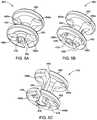
- FIG. 6Ais a top view of a base of burr hole plug
- FIG. 6Bis perspective view of the guide base of FIG. 5B with the base of the burr hole plug of FIG. 6A attached;
- FIG. 7Ais perspective view of one embodiment of a drill shank of the kit or arrangement of FIG. 4A ;
- FIG. 7Bis a side view of one embodiment of a drill for use with the drill shank of FIG. 7A ;
- FIG. 8is perspective view of one embodiment of a guide collet of the kit or arrangement of FIG. 4A ;
- FIG. 9Ais perspective view illustrating use of the guide base and drill shank of the kit or arrangement of FIG. 4A ;
- FIG. 9Bis perspective view illustrating use of the guide base and guide collet of the kit or arrangement of FIG. 4A ;
- FIG. 9Cis perspective view illustrating the base of a burr hole plug attached to a skull using the kit or arrangement of FIG. 4A .
- the present disclosureis directed to the area of burr hole plugs and kits and methods for securing burr hole plugs.
- the present disclosureis also directed to implantable electrical stimulation systems including the kits for securing burr hole plugs, as well as methods of making and using the kits, burr hole plugs, and electrical stimulation systems.
- Suitable implantable electrical stimulation systemsinclude, but are not limited to, a least one lead with one or more electrodes disposed on a distal portion of the lead and one or more terminals disposed on one or more proximal portions of the lead.
- Leadsinclude, for example, percutaneous leads, paddle leads, cuff leads, or any other arrangement of electrodes on a lead. Examples of electrical stimulation systems with leads are found in, for example, U.S. Pat. Nos.
- 2007/01500362009/0187222; 2009/0276021; 2010/0076535; 2010/0268298; 2011/0005069; 2011/0004267; 2011/0078900; 2011/0130817; 2011/0130818; 2011/0238129; 2011/0313500; 2012/0016378; 2012/0046710; 2012/0071949; 2012/0165911; 2012/0197375; 2012/0203316; 2012/0203320; 2012/0203321; 2012/0316615; 2013/0105071; and 2013/0197602, all of which are incorporated by reference.
- a percutaneous leadwill be exemplified, but it will be understood that the methods and systems described herein are also applicable to paddle leads and other leads.
- a percutaneous lead for electrical stimulation(for example, deep brain, spinal cord, peripheral nerve, or cardiac-tissue) includes stimulation electrodes that can be ring electrodes, segmented electrodes that extend only partially around the circumference of the lead, or any other type of electrode, or any combination thereof.
- the segmented electrodescan be provided in sets of electrodes, with each set having electrodes circumferentially distributed about the lead at a particular longitudinal position.
- a set of segmented electrodescan include any suitable number of electrodes including, for example, two, three, four, or more electrodes.
- the leadsare described herein relative to use for deep brain stimulation, but it will be understood that such leads can be used for applications other than deep brain stimulation, including spinal cord stimulation, peripheral nerve stimulation, dorsal root ganglion stimulation, sacral nerve stimulation, or stimulation of other nerves, muscles, and tissues.
- an electrical stimulation system 10includes one or more stimulation leads 12 and an implantable pulse generator (IPG) 14 .
- the system 10can also include one or more of an external remote control (RC) 16 , a clinician's programmer (CP) 18 , an external trial stimulator (ETS) 20 , or an external charger 22 .
- RCremote control
- CPclinician's programmer
- ETSexternal trial stimulator
- the IPG 14is physically connected, optionally, via one or more lead extensions 24 , to the stimulation lead(s) 12 .
- Each leadcarries multiple electrodes 26 arranged in an array.
- the IPG 14includes pulse generation circuitry that delivers electrical stimulation energy in the form of, for example, a pulsed electrical waveform (i.e., a temporal series of electrical pulses) to the electrode array 26 in accordance with a set of stimulation parameters.
- the implantable pulse generatorcan be implanted into a patient's body, for example, below the patient's clavicle area or within the patient's abdominal cavity.
- the implantable pulse generatorcan have eight stimulation channels which may be independently programmable to control the magnitude of the current stimulus from each channel.
- the implantable pulse generatorcan have more or fewer than eight stimulation channels (e.g., 4-, 6-, 16-, 32-, or more stimulation channels).
- the implantable pulse generatorcan have one, two, three, four, or more connector ports, for receiving the terminals of the leads and/or lead extensions.
- the ETS 20may also be physically connected, optionally via the percutaneous lead extensions 28 and external cable 30 , to the stimulation leads 12 .
- the ETS 20which may have similar pulse generation circuitry as the IPG 14 , also delivers electrical stimulation energy in the form of, for example, a pulsed electrical waveform to the electrode array 26 in accordance with a set of stimulation parameters.
- One difference between the ETS 20 and the IPG 14is that the ETS 20 is often a non-implantable device that is used on a trial basis after the neurostimulation leads 12 have been implanted and prior to implantation of the IPG 14 , to test the responsiveness of the stimulation that is to be provided. Any functions described herein with respect to the IPG 14 can likewise be performed with respect to the ETS 20 .
- the RC 16may be used to telemetrically communicate with or control the IPG 14 or ETS 20 via a uni- or bi-directional wireless communications link 32 . Once the IPG 14 and neurostimulation leads 12 are implanted, the RC 16 may be used to telemetrically communicate with or control the IPG 14 via a uni- or bi-directional communications link 34 . Such communication or control allows the IPG 14 to be turned on or off and to be programmed with different stimulation parameter sets. The IPG 14 may also be operated to modify the programmed stimulation parameters to actively control the characteristics of the electrical stimulation energy output by the IPG 14 .
- the CP 18allows a user, such as a clinician, the ability to program stimulation parameters for the IPG 14 and ETS 20 in the operating room and in follow-up sessions. Alternately, or additionally, stimulation parameters can be programed via wireless communications (e.g., Bluetooth) between the RC 16 (or external device such as a hand-held electronic device) and the IPG 14 .
- wireless communicationse.g
- the CP 18may perform this function by indirectly communicating with the IPG 14 or ETS 20 , through the RC 16 , via a wireless communications link 36 . Alternatively, the CP 18 may directly communicate with the IPG 14 or ETS 20 via a wireless communications link (not shown).
- the stimulation parameters provided by the CP 18are also used to program the RC 16 , so that the stimulation parameters can be subsequently modified by operation of the RC 16 in a stand-alone mode (i.e., without the assistance of the CP 18 ).
- control moduleis used herein to describe a pulse generator (e.g., the IPG 14 or the ETS 20 of FIG. 1 ). Stimulation signals generated by the control module are emitted by electrodes of the lead(s) to stimulate patient tissue.
- the electrodes of the lead(s)are electrically coupled to terminals of the lead(s) that, in turn, are electrically coupleable with the control module.
- the lead(s)couple(s) directly with the control module.
- one or more intermediary devicese.g., a lead extension, an adaptor, a splitter, or the like are disposed between the lead(s) and the control module.
- Percutaneous leadsare described herein for clarity of illustration. It will be understood that paddle leads and cuff leads can be used in lieu of, or in addition to, percutaneous leads.
- the leads described hereininclude 8 electrodes. It will be understood that the leads could include any suitable number of electrodes.
- the leadscan include ring electrodes, a distal-tip electrode, and/or one or more segmented electrodes in lieu of, or in addition to, one or more ring electrodes.
- the term “elongated member” used hereinincludes leads (e.g., percutaneous, paddle, cuff, or the like), as well as intermediary devices (e.g., lead extensions, adaptors, splitters, or the like).
- FIG. 2illustrates one embodiment of a lead 100 with electrodes 125 disposed at least partially about a circumference of the lead 100 along a distal end portion of the lead and terminals 135 disposed along a proximal end portion of the lead 100 .
- the lead 100can be implanted near or within the desired portion of the body to be stimulated such as, for example, the brain, spinal cord, or other body organs or tissues.
- access to the desired position in the braincan be accomplished by drilling a hole in the patient's skull or cranium with a cranial drill (commonly referred to as a burr), and coagulating and incising the dura mater, or brain covering.
- a burrcommonly referred to as a burr
- the lead 100can be inserted into the cranium and brain tissue with the assistance of a stylet (not shown).
- the lead 100can be guided to the target location within the brain using, for example, a stereotactic frame and a microdrive motor system.
- the microdrive motor systemcan be fully or partially automatic.
- the microdrive motor systemmay be configured to perform one or more the following actions (alone or in combination): insert the lead 100 , advance the lead 100 , retract the lead 100 , or rotate the lead 100 .
- the lead 100 for deep brain stimulationcan include stimulation electrodes, recording electrodes, or both.
- the lead 100is rotatable so that the stimulation electrodes can be aligned with the target neurons after the neurons have been located using the recording electrodes.
- Stimulation electrodesmay be disposed on the circumference of the lead 100 to stimulate the target neurons. Stimulation electrodes may be ring-shaped so that current projects from each electrode equally in every direction from the position of the electrode along a length of the lead 100 . In the embodiment of FIG. 2 , two of the electrodes 125 are ring electrodes 120 . Ring electrodes 120 typically do not enable stimulus current to be directed from only a limited angular range around of the lead 100 . Segmented electrodes 130 , however, can be used to direct stimulus current to a selected angular range around the lead 100 .
- segmented electrodes 130When segmented electrodes 130 are used in conjunction with an implantable pulse generator that delivers constant current stimulus, current steering can be achieved to more precisely deliver the stimulus to a position around an axis of the lead 100 (i.e., radial positioning around the axis of the lead 100 ). To achieve current steering, segmented electrodes 130 can be utilized in addition to, or as an alternative to, ring electrodes 120 .
- the lead 100includes a lead body 110 , terminals 135 , and one or more ring electrodes 120 and one or more sets of segmented electrodes 130 (or any other combination of electrodes).
- the lead body 110can be formed of a biocompatible, non-conducting material such as, for example, a polymeric material. Suitable polymeric materials include, but are not limited to, silicone, polyurethane, polyurea, polyurethane-urea, polyethylene, or the like.
- the lead 100may be in contact with body tissue for extended periods of time.
- the lead 100has a cross-sectional diameter of no more than 1.5 mm and may be in the range of 0.5 to 1.5 mm.
- the lead 100has a length of at least 10 cm and the length of the lead 100 may be in the range of 10 to 70 cm.
- the electrodes 125can be made using a metal, alloy, conductive oxide, or any other suitable conductive biocompatible material.
- suitable materialsinclude, but are not limited to, platinum, platinum iridium alloy, iridium, titanium, tungsten, palladium, palladium rhodium, or the like.
- the electrodesare made of a material that is biocompatible and does not substantially corrode under expected operating conditions in the operating environment for the expected duration of use.
- Each of the electrodescan either be used (ON) or unused (OFF).
- the electrodecan be used as an anode or cathode and carry anodic or cathodic current.
- an electrodemight be an anode for a period of time and a cathode for a period of time.
- deep brain stimulation leads and other leadsmay include one or more sets of segmented electrodes. Segmented electrodes may provide for superior current steering than ring electrodes because target structures in deep brain stimulation are not typically symmetric about the axis of the distal electrode array. Instead, a target may be located on one side of a plane running through the axis of the lead.
- RSEAradially segmented electrode array
- current steeringcan be performed not only along a length of the lead but also around a circumference of the lead. This provides precise three-dimensional targeting and delivery of the current stimulus to neural target tissue, while potentially avoiding stimulation of other tissue. Examples of leads with segmented electrodes include U.S. Pat. Nos.
- Segmented electrodescan also be used for other stimulation techniques including, but not limited to, spinal cord stimulation, peripheral nerve stimulation, dorsal root ganglion stimulation, or stimulation of other nerves, muscles, and tissues.
- FIG. 3is a schematic overview of one embodiment of components of an electrical stimulation system 300 including an electronic subassembly 358 disposed within a control module.
- the electronic subassembly 358may include one or more components of the IPG. It will be understood that the electrical stimulation system can include more, fewer, or different components and can have a variety of different configurations including those configurations disclosed in the stimulator references cited herein.
- a power source 312for example, a power source 312 , one or more antennas 318 , a receiver 302 , and a processor 304
- the electrical stimulation systemcan be positioned on one or more circuit boards or similar carriers within a sealed electronics housing of an implantable pulse generator (see e.g., 14 in FIG. 1 ), if desired.
- Any power source 312can be used including, for example, a battery such as a primary battery or a rechargeable battery.
- Examples of other power sourcesinclude super capacitors, nuclear or atomic batteries, mechanical resonators, infrared collectors, thermally-powered energy sources, flexural powered energy sources, bioenergy power sources, fuel cells, bioelectric cells, osmotic pressure pumps, and the like including the power sources described in U.S. Pat. No. 7,437,193, incorporated herein by reference.
- powercan be supplied by an external power source through inductive coupling via the optional antenna 318 or a secondary antenna.
- the antenna 318(or the secondary antenna) is implemented using the auxiliary electrically-conductive conductor.
- the external power sourcecan be in a device that is mounted on the skin of the user or in a unit that is provided near the user on a permanent or periodic basis.
- the batterymay be recharged using the optional antenna 318 , if desired. Power can be provided to the battery for recharging by inductively coupling the battery through the antenna to a recharging unit 316 external to the user. Examples of such arrangements can be found in the references identified above.
- the electronic subassembly 358 and, optionally, the power source 312can be disposed within a control module (e.g., the IPG 14 or the ETS 20 of FIG. 1 ).
- electrical stimulation signalsare emitted by the electrodes (e.g., electrode array 26 in FIG. 1 ) to stimulate nerve fibers, muscle fibers, or other body tissues near the electrical stimulation system.
- the processor 304is generally included to control the timing and electrical characteristics of the electrical stimulation system. For example, the processor 304 can, if desired, control one or more of the timing, frequency, strength, duration, and waveform of the pulses. In addition, the processor 304 can select which electrodes can be used to provide stimulation, if desired. In some embodiments, the processor 304 selects which electrode(s) are cathodes and which electrode(s) are anodes. In some embodiments, the processor 304 is used to identify which electrodes provide the most useful stimulation of the desired tissue.
- processorscan be used and may be an electronic device that, for example, produces pulses at a regular interval or the processor can be capable of receiving and interpreting instructions from an external programming unit 308 that, for example, allows modification of pulse characteristics.
- the processor 304is coupled to a receiver 302 which, in turn, is coupled to the optional antenna 318 . This allows the processor 304 to receive instructions from an external source to, for example, direct the pulse characteristics and the selection of electrodes, if desired.
- the antenna 318is capable of receiving signals (e.g., RF signals) from an external telemetry unit 306 which is programmed by the programming unit 308 .
- the programming unit 308can be external to, or part of, the telemetry unit 306 .
- the telemetry unit 306can be a device that is worn on the skin of the user or can be carried by the user and can have a form similar to a pager, cellular phone, or remote control, if desired.
- the telemetry unit 306may not be worn or carried by the user but may only be available at a home station or at a clinician's office.
- the programming unit 308can be any unit that can provide information to the telemetry unit 306 for transmission to the electrical stimulation system 300 .
- the programming unit 308can be part of the telemetry unit 306 or can provide signals or information to the telemetry unit 306 via a wireless or wired connection.
- One example of a suitable programming unit 308is a computer operated by the user or clinician to send signals to the telemetry unit 306 .
- the signals sent to the processor 304 via the antenna 318 and the receiver 302can be used to modify or otherwise direct the operation of the electrical stimulation system.
- the signalsmay be used to modify the pulses of the electrical stimulation system such as modifying one or more of pulse duration, pulse frequency, pulse waveform, and pulse strength.
- the signalsmay also direct the electrical stimulation system 300 to cease operation, to start operation, to start charging the battery, or to stop charging the battery.
- the stimulation systemdoes not include the antenna 318 or receiver 302 and the processor 304 operates as programmed.
- the electrical stimulation system 300may include a transmitter (not shown) coupled to the processor 304 and the antenna 318 for transmitting signals back to the telemetry unit 306 or another unit capable of receiving the signals.
- the electrical stimulation system 300may transmit signals indicating whether the electrical stimulation system 300 is operating properly or not or indicating when the battery needs to be charged or the level of charge remaining in the battery.
- the processor 304may also be capable of transmitting information about the pulse characteristics so that a user or clinician can determine or verify the characteristics.
- a leadwhen a lead is implanted into the brain of a patient, the lead is inserted through a burr hole in the skull of the patient.
- the leadextends out of the burr hole and is coupled to a control module implanted elsewhere, for example, in the torso of the patient.
- a burr hole plugis provided in the burr hole to cover the opening through the skull, to protect the lead exiting the skull, and to firmly hold the lead in place to prevent or reduce lead migration within the brain.
- At least some current burr hole plug placement methodsprovide little or no aid in controlling the placement, insertion, and fixation of mounting screws into the skull to hold the burr hole plug in place.
- the procedure of positioning and assuring secure fixation of the burr hole plugis often difficult due to the small size of the components, the hardness of the skull, and other factors. For example, it may be difficult to align the screws on the skull and insert the screws into the skull at the desired position for proper placement.
- a screw headcan be easily stripped, which may create sharp edges in the place of engagement with the screwdriver. This can result in a future internal hemorrhage or skin erosion.
- FIGS. 4A and 4Billustrate one embodiment of a kit 450 or arrangement for placement, securement, and fixation of a burr hole plug to a patient's skull.
- the kit 450includes a guide base 452 , a drill shank 454 , and one or more guide collets 456 .
- Other kitsmay include more or fewer components than kit 450 illustrated in FIGS. 4A and 4B .
- the kit 450may also include a base 470 ( FIG. 6A ) for the burr hole plug. In other embodiments, the base 470 may be obtained from a separate burr hole plug.
- the kit 450may also include the complete burr hole plug arrangement.
- burr hole plugscan be found at U.S. Pat. Nos. 7,479,146; 8,043,304; 8,137,362; 8,425,534; 8,731,686; 8,764,767; 8,812,133; 9,043,000; and 9,050,191; and U.S. Patent Application Publications Nos. 2012/0316628 and 2013/0066430, all of which are incorporated herein by reference. It will be understood that other burr hole plugs may also be used with kit 450 .
- the kit 450includes the guide base 452 and the drill shank 454 for pre-drilling pilot holes for the mounting fasteners of the burr hole plug.
- the one or more guide collets 456in cooperation with the guide base 452 , facilitate insertion and securement of the mounting fasteners to the skull.
- FIGS. 5A, 5B, and 5Cillustrate three embodiments of the guide base 452 .
- the guide base 452can be made of metal, rigid plastic, or any other suitable material, or any combination thereof.
- the guide base 452includes an upper flange 460 , a lower flange 462 , and a connecting member 464 coupling the upper and lower flanges. Both the upper and lower flanges 460 , 462 define one or more guide holes 466 a , 466 b for guiding the drill shank 454 and the guide collets 456 .
- each of the upper and lower flanges 460 , 462 of the guide base 452has two guide holes 466 a , 466 b because two fasteners are used to attach the burr hole plug to the skull.
- the guide holes 466 a of the upper flange 460are aligned with the guide holes 466 b of the lower flange 462 .
- other guide basesmay have a different number of guide holes including, but not limited to, one, three, or four guide holes.
- each of the upper and lower flanges 460 , 462 of the guide base 452has a number of guide holes 466 a , 466 b equal to a number of screws or other fasteners that will be used to secure the burr hole plug to the skull of the patient.
- the connecting member 464is hollow to provide access or viewing through the burr hole.
- the guide base 452also optionally defines a gap 468 extending into at least the lower flange 462 and may also extend into the upper flange 460 or the connecting member 464 (or any combination thereof) as shown in the illustrated embodiments.
- the guide base 452is used after implantation of the lead and the portion of the implanted lead which exits the burr hole can be inserted into or through, and remain positioned within, the gap 468 during use of the guide base 452 .
- the guide base 452includes an alignment arrangement for aligning, and optionally attaching or fixing, the guide base to a base of a burr hole plug.
- FIG. 6Aillustrates one embodiment of a base 470 of a burr hole plug including one or more fastener receiving opening 472 , an optional alignment pin opening 473 , and a burr hole opening 474 .
- the alignment arrangement on the guide base 452takes the form of one or more sections 476 (for example, one or more curved walls) of a ring that extend from the lower flange 462 .
- the one or more sections 476fit into the burr hole opening 474 of the base 470 of the burr hole plug to align the base 470 with the guide base 452 , as illustrated in FIG. 6B .
- the sections 476form a friction fit or a compression fit with the base to hold the base 470 on the guide base 452 .
- the fastener receiving openings 472 of the base 470 of the burr hole plugare aligned with the one or more guide holes 466 b of the lower flange 462 of the guide base 452 .
- the alignment arrangement on the guide base 452includes the one or more section 476 of a ring and an alignment pin 469 .
- the alignment pin 469can be inserted into the alignment opening 473 ( FIG. 6A ) on the base 470 . It will be understood that in other embodiments the alignment pin 469 can be on the base 470 and the alignment opening 473 can be on the guide base 452
- the alignment arrangement on the guide base 452includes multiple pins 478 that can fit in corresponding holes, slots, or other elements of the base 470 of the burr hole plug. It will be understood that any other suitable alignment arrangement or combination of alignment arrangements can be used.
- the guide base 452includes pins 478 and sections 476 of a ring that fit into the burr hole opening 474 of the base 470 of the burr hole plug.
- one of the pins 478can serve the same function as the alignment pin 469 of FIG. 5B .
- FIG. 7Aillustrates one embodiment of a drill shank 454 that includes a cutting element 480 , a main shaft 482 , and a drill engagement region 484 .
- the main shaft 482has a sloping section 481 that leads to the cutting element 480 .
- the drill shank 454is typically made of metal but may also include other hard substances to facilitate drilling into the skull of the patient.
- the drill engagement region 484is configured to fit and lock into a drill 486 , illustrated in FIG. 7B .
- the drill engagement region 484can have any suitable arrangement and may be dependent on the drill 486 that is used. Any suitable drill 486 , including surgical drills, can be used.
- the drill 486may be part of the kit 450 or may be separate from the kit.
- the cutting element 480 of the drill shank 454is sized in diameter to produce pilot holes for the screws (or other fasteners) of the burr hole plug.
- the outer diameter of the cutting element 480may be equal to or smaller than the outer diameter of the fasteners that will be used.
- the main shaft 482 of the drill shank 454has an outer diameter 483 that is smaller than the inner diameter of the guide hole 466 a of the upper flange 460 of the guide base 452 .
- the main shaft 482 of the drill shank 454can be inserted through the guide hole 466 a of the upper flange 460 in order to drill a pilot hole in the skull of the patient.
- the upper flange 460provides a guide for the drill shank 454 to reliably drill the pilot hole at the desired position on the skull.
- the guide hole 466 b in the lower flange 462 of the guide base 452also provides a guide for the drill shank 454 .
- the guide hole 466 b and lower flange 462may act as a stop for the drill shank 454 to limit the depth of the pilot hole or to prevent or hinder drilling too deeply into the skull of the patient.
- the guide hole 466 b of the lower flange 462has an inner diameter that is less than the outer diameter 483 of the main shaft 482 of the drill shank 454 so that the main shaft 482 (or at least the non-sloping portion of the main shaft) is stopped at the lower flange 462 .
- the surface of the guide hole 466 bmay be sloping so that the inner diameter of the guide hole 466 b decreases toward the portion of the guide base 452 that is positioned closest to the patient's skull.
- the inner diameter of the guide hole 466 bis smaller than the outer diameter 483 of the main shaft 482 (or at least the non-sloping portion of the main shaft) of the drill shank 454 .
- the main shaft 482(or the non-sloping portion of the main shaft) is stopped at some position along the guide hole 466 b of the lower flange 462 of the guide base 452 .
- FIG. 8illustrates one embodiment of a guide collet 456 which includes a collet flange 488 , a hollow collet shaft 490 , a fastener tube 492 , and, optionally, a fastener 494 , such as a screw.
- the fastener 494is included with the guide collet 456 and, in other embodiments, the fastener is included with the burr hole plug and inserted into the guide collet 456 prior to use.
- the collet flange 488 and collet shaft 490can be made of metal or rigid plastic.
- the fastener tube 492can be made of flexible or rigid plastic or metal.
- the collet flange 488has an outer diameter that is greater than the outer diameter of the guide hole 466 a of the upper flange 460 .
- the collet shaft 490has an outer diameter that is less than the outer diameter of the guide hole 466 a of the upper flange 460 .
- the guide hole 466 a of the upper flange 460may be countersunk to enable the collet flange 488 to fit fully or partially within an upper portion of the guide hole 466 a.
- the length of the collet shaft 490 and fastener tube 492are selected so that the distal portion of the fastener tube 492 is disposed within the guide hole 466 b of the lower flange 462 when the guide collet 456 is inserted into the guide base 452 .
- the fastener tube 492 and openings in the collet flange 488 and collet shaft 490are selected so that a tool such as a screwdriver (preferably, a torque limiting screwdriver) or other appropriate tool can be inserted through the collet flange, collet shaft, and fastener tube and engage the fastener to drive the fastener into the skull and secure the base 470 of the burr hole plug.
- FIGS. 9A-9Cillustrate the use of the components of the kit.
- the guide base 452 and the base 470 ( FIG. 9C ) of the burr hole plugare placed over the burr hole formed in the skull 498 of a patient.
- the drill shank 454is attached to a drill (not shown) and then sequentially inserted into each of the guide holes 466 a of the guide base 452 to drill a pilot hole in the skull.
- the guide collets 456with associated fasteners 494 ( FIG. 9C ) are inserted into the guide holes 466 a of the guide base 452 and the fasteners are then driven into the skull using the drilled pilot holes.
- the guide base 452is removed leaving the base 470 of the burr hole plug attached to the skull 498 with the fasteners 494 .
Landscapes
- Health & Medical Sciences (AREA)
- Life Sciences & Earth Sciences (AREA)
- Surgery (AREA)
- Heart & Thoracic Surgery (AREA)
- General Health & Medical Sciences (AREA)
- Veterinary Medicine (AREA)
- Engineering & Computer Science (AREA)
- Biomedical Technology (AREA)
- Nuclear Medicine, Radiotherapy & Molecular Imaging (AREA)
- Public Health (AREA)
- Animal Behavior & Ethology (AREA)
- Oral & Maxillofacial Surgery (AREA)
- Medical Informatics (AREA)
- Molecular Biology (AREA)
- Neurosurgery (AREA)
- Psychology (AREA)
- Neurology (AREA)
- Dentistry (AREA)
- Orthopedic Medicine & Surgery (AREA)
- Cardiology (AREA)
- Radiology & Medical Imaging (AREA)
- Pathology (AREA)
- Electrotherapy Devices (AREA)
Abstract
Description
Claims (20)
Priority Applications (1)
| Application Number | Priority Date | Filing Date | Title |
|---|---|---|---|
| US16/351,350US11013913B2 (en) | 2018-03-16 | 2019-03-12 | Kits and methods for securing a burr hole plugs for stimulation systems |
Applications Claiming Priority (2)
| Application Number | Priority Date | Filing Date | Title |
|---|---|---|---|
| US201862643964P | 2018-03-16 | 2018-03-16 | |
| US16/351,350US11013913B2 (en) | 2018-03-16 | 2019-03-12 | Kits and methods for securing a burr hole plugs for stimulation systems |
Publications (2)
| Publication Number | Publication Date |
|---|---|
| US20190282802A1 US20190282802A1 (en) | 2019-09-19 |
| US11013913B2true US11013913B2 (en) | 2021-05-25 |
Family
ID=66001322
Family Applications (1)
| Application Number | Title | Priority Date | Filing Date |
|---|---|---|---|
| US16/351,350Expired - Fee RelatedUS11013913B2 (en) | 2018-03-16 | 2019-03-12 | Kits and methods for securing a burr hole plugs for stimulation systems |
Country Status (3)
| Country | Link |
|---|---|
| US (1) | US11013913B2 (en) |
| EP (1) | EP3765142B1 (en) |
| WO (1) | WO2019178145A1 (en) |
Families Citing this family (3)
| Publication number | Priority date | Publication date | Assignee | Title |
|---|---|---|---|---|
| US11602402B2 (en)* | 2018-12-04 | 2023-03-14 | Globus Medical, Inc. | Drill guide fixtures, cranial insertion fixtures, and related methods and robotic systems |
| GB2604397A (en) | 2021-03-05 | 2022-09-07 | Qv Bioelectronics Ltd | Cranial Prosthetic |
| WO2023129532A1 (en)* | 2021-12-29 | 2023-07-06 | Cerebral Therapeutics, Inc. | Ventricular drain or shunt assembly with recording electrode |
Citations (237)
| Publication number | Priority date | Publication date | Assignee | Title |
|---|---|---|---|---|
| US979652A (en) | 1910-03-11 | 1910-12-27 | Standard Electric Fittings Company | Gas connection for outlet-boxes. |
| US2186277A (en) | 1938-11-21 | 1940-01-09 | Gen Motors Corp | Grommet seal |
| US2521301A (en) | 1950-09-05 | Morrison | ||
| US2873822A (en) | 1954-02-03 | 1959-02-17 | Cushman Chuck Co | Bolt-type locking mechanisms for indexing devices |
| US2912712A (en) | 1955-10-31 | 1959-11-17 | William S Shamban | One-piece grommet |
| US3758827A (en) | 1971-06-18 | 1973-09-11 | Philips Corp | Piezoelectric ignition device |
| US3826952A (en) | 1972-09-14 | 1974-07-30 | Rion Co | High voltage generating device |
| US3829737A (en) | 1972-07-28 | 1974-08-13 | Genoud & Cie Sa | Piezo-electric lighters |
| US4114603A (en) | 1976-08-06 | 1978-09-19 | Wilkinson Harold A | Intracranial pressure monitoring catheter |
| JPS55112538A (en) | 1979-02-23 | 1980-08-30 | Hitachi Ltd | Local overheat diagnostic unit of rotary electric machine |
| US4245645A (en) | 1977-09-28 | 1981-01-20 | Arseneault Pierre Michel | Self-locking cerebral electrical probe |
| US4297609A (en) | 1979-04-06 | 1981-10-27 | Matsushita Electric Industrial Co., Ltd. | High-voltage generating device |
| US4315180A (en) | 1976-06-10 | 1982-02-09 | Matsushita Electric Industrial Co., Ltd. | High voltage piezoelectric generating device with lengthened spark time |
| US4328313A (en) | 1979-12-19 | 1982-05-04 | The United States Of America As Represented By The Secretary Of The Navy | Method of producing a plaque dispersing enzyme |
| US4328813A (en) | 1980-10-20 | 1982-05-11 | Medtronic, Inc. | Brain lead anchoring system |
| US4467800A (en) | 1982-04-16 | 1984-08-28 | Medtronic, Inc. | Tool for creating a pocket for a epidural electrode |
| US4741571A (en) | 1986-12-15 | 1988-05-03 | Dura Corporation | Manually foldable top for automobile vehicles |
| US4805634A (en) | 1986-06-06 | 1989-02-21 | Hellige Gmbh | Adapter assembly for use with a cranial biosensor |
| US4826487A (en) | 1987-05-04 | 1989-05-02 | Victory Engineering Company | Alignment button for stereotaxic plug and method of using the same |
| US4850359A (en) | 1987-10-16 | 1989-07-25 | Ad-Tech Medical Instrument Corporation | Electrical brain-contact devices |
| US4931056A (en) | 1987-09-04 | 1990-06-05 | Neurodynamics, Inc. | Catheter guide apparatus for perpendicular insertion into a cranium orifice |
| US4955891A (en) | 1985-07-02 | 1990-09-11 | Ohio Medical Instrument Company, Inc. | Method and apparatus for performing stereotactic surgery |
| US4998938A (en) | 1988-06-09 | 1991-03-12 | Neurodynamics, Inc. | Removable skull mounted work platform and method of assembling same |
| US5116345A (en) | 1990-11-28 | 1992-05-26 | Ohio Medical Instrument Co., Inc. | Stereotactically implanting an intracranial device |
| US5193540A (en) | 1991-12-18 | 1993-03-16 | Alfred E. Mann Foundation For Scientific Research | Structure and method of manufacture of an implantable microstimulator |
| US5193539A (en) | 1991-12-18 | 1993-03-16 | Alfred E. Mann Foundation For Scientific Research | Implantable microstimulator |
| US5201737A (en) | 1991-04-11 | 1993-04-13 | Oswald Leibinger Gmbh | Plate for covering a drill hole in a skull cap and for fixing a cranial bone cover |
| US5235990A (en) | 1991-06-28 | 1993-08-17 | Dempsey Robert N | Apparatus for neutralizing irritants introduced into a body via a bite or sting |
| US5300080A (en) | 1991-11-01 | 1994-04-05 | David Clayman | Stereotactic instrument guided placement |
| US5330485A (en) | 1991-11-01 | 1994-07-19 | Clayman David A | Cerebral instrument guide frame and procedures utilizing it |
| US5464446A (en) | 1993-10-12 | 1995-11-07 | Medtronic, Inc. | Brain lead anchoring system |
| US5484445A (en) | 1993-10-12 | 1996-01-16 | Medtronic, Inc. | Sacral lead anchoring system |
| US5496356A (en) | 1993-03-29 | 1996-03-05 | Hudz; Paul H. | Piezo de-toxifier |
| US5503164A (en) | 1994-01-28 | 1996-04-02 | Osteogenics, Inc. | Device and method for repair of craniomaxillofacial bone defects including burr holes |
| US5549620A (en) | 1994-12-06 | 1996-08-27 | Bremer; Paul | Brain surgery with craniotomy pin |
| US5707373A (en) | 1996-04-26 | 1998-01-13 | Ikonos Corporation | Bone fastener and instrument for insertion thereof |
| WO1998008554A1 (en) | 1996-08-29 | 1998-03-05 | Medtronic, Inc. | Brain stimulation system having an improved anchor for a lead or catheter |
| US5732699A (en) | 1992-02-20 | 1998-03-31 | Humanteknik Ab | Device for securing an object to a surface by vacuum |
| US5776144A (en) | 1996-05-10 | 1998-07-07 | Implex Gmbh Spezialhorgerate | Device for positioning and fixing of therapeutic, surgical, or diagnostic instruments |
| US5800504A (en) | 1996-01-19 | 1998-09-01 | La Tecnica S.R.L. | Portable device for treating insect bites |
| US5843150A (en) | 1997-10-08 | 1998-12-01 | Medtronic, Inc. | System and method for providing electrical and/or fluid treatment within a patient's brain |
| US5891028A (en) | 1994-07-01 | 1999-04-06 | Humanteknik Ab | Interface element for a biomedical electrode |
| US5897531A (en) | 1994-01-07 | 1999-04-27 | Amirana; Omar | Adhesive surgical retaining device |
| EP0911061A2 (en) | 1997-10-27 | 1999-04-28 | Neuropace, Inc. | System for the treatment of neurological disorders |
| US5916154A (en) | 1998-04-22 | 1999-06-29 | Nellcor Puritan Bennett | Method of enhancing performance in pulse oximetry via electrical stimulation |
| US5927277A (en) | 1995-04-28 | 1999-07-27 | Medtronic, Inc. | Method and apparatus for securing probes within a burr hole |
| US5954687A (en) | 1995-04-28 | 1999-09-21 | Medtronic, Inc. | Burr hole ring with catheter for use as an injection port |
| WO1999055408A1 (en) | 1998-04-29 | 1999-11-04 | Medtronic, Inc. | Burr hole ring with integral lead/catheter fixation device |
| US5984930A (en) | 1996-09-30 | 1999-11-16 | George S. Allen | Biopsy guide |
| US5993463A (en) | 1997-05-15 | 1999-11-30 | Regents Of The University Of Minnesota | Remote actuation of trajectory guide |
| US6006124A (en) | 1998-05-01 | 1999-12-21 | Neuropace, Inc. | Means and method for the placement of brain electrodes |
| WO2000013743A1 (en) | 1998-09-03 | 2000-03-16 | Surgical Navigation Technologies, Inc. | Anchoring system for a brain lead |
| US6050098A (en) | 1998-04-29 | 2000-04-18 | American Standard Inc. | Use of electronic expansion valve to maintain minimum oil flow |
| US6050998A (en) | 1999-05-21 | 2000-04-18 | Stephen A. Fletcher | Bone fastener |
| US6073048A (en) | 1995-11-17 | 2000-06-06 | Medtronic, Inc. | Baroreflex modulation with carotid sinus nerve stimulation for the treatment of heart failure |
| US6094598A (en) | 1996-04-25 | 2000-07-25 | Medtronics, Inc. | Method of treating movement disorders by brain stimulation and drug infusion |
| US6117143A (en) | 1998-09-11 | 2000-09-12 | Hybex Surgical Specialties, Inc. | Apparatus for frameless stereotactic surgery |
| US6126663A (en) | 1999-04-15 | 2000-10-03 | Hair; John Hunter | Expandable bone connector |
| US6128537A (en) | 1997-05-01 | 2000-10-03 | Medtronic, Inc | Techniques for treating anxiety by brain stimulation and drug infusion |
| US6134477A (en) | 1999-04-30 | 2000-10-17 | Medtronic, Inc. | Adjustable medical lead fixation system |
| US6171239B1 (en) | 1998-08-17 | 2001-01-09 | Emory University | Systems, methods, and devices for controlling external devices by signals derived directly from the nervous system |
| US6181969B1 (en) | 1998-06-26 | 2001-01-30 | Advanced Bionics Corporation | Programmable current output stimulus stage for implantable device |
| US6200329B1 (en) | 1998-08-31 | 2001-03-13 | Smith & Nephew, Inc. | Suture collet |
| US6210417B1 (en) | 1999-04-29 | 2001-04-03 | Medtronic, Inc. | Medical lead positioning and anchoring system |
| US6224450B1 (en) | 1998-08-28 | 2001-05-01 | Laurie J. Norton | Cycling activity belt |
| US6230049B1 (en) | 1999-08-13 | 2001-05-08 | Neuro Pace, Inc. | Integrated system for EEG monitoring and electrical stimulation with a multiplicity of electrodes |
| US6269270B1 (en) | 1998-10-26 | 2001-07-31 | Birinder Bob Boveja | Apparatus and method for adjunct (add-on) therapy of Dementia and Alzheimer's disease utilizing an implantable lead and external stimulator |
| US6271094B1 (en) | 2000-02-14 | 2001-08-07 | International Business Machines Corporation | Method of making MOSFET with high dielectric constant gate insulator and minimum overlap capacitance |
| US6284729B1 (en) | 1996-11-06 | 2001-09-04 | Children's Medical Center Corporation | Methods and reagents for regulating obesity |
| US6295944B1 (en) | 2000-06-20 | 2001-10-02 | J Timothy Lovett | Automatic tethering system for a floating dock |
| US6321104B1 (en) | 1998-11-05 | 2001-11-20 | Medtronic, Inc. | Burr hole cap for fixation of cranial lead |
| US6324433B1 (en) | 2000-01-20 | 2001-11-27 | Electrocare Technologies, Llc | Electrode-lead coupling skull mounted port assembly |
| US20010051819A1 (en) | 1997-10-27 | 2001-12-13 | Fischell Robert E. | Implantable apparatus for treating neurological disorders |
| US20010056290A1 (en) | 1997-10-27 | 2001-12-27 | Fischell Robert E. | Methods for responsively treating neurological disorders |
| US6353762B1 (en) | 1999-04-30 | 2002-03-05 | Medtronic, Inc. | Techniques for selective activation of neurons in the brain, spinal cord parenchyma or peripheral nerve |
| US6354299B1 (en) | 1997-10-27 | 2002-03-12 | Neuropace, Inc. | Implantable device for patient communication |
| US6356729B1 (en) | 1999-04-07 | 2002-03-12 | Ricoh Company, Ltd. | Electrophotographic toner, toner container containing the toner, image forming apparatus using the toner container and method for supplying the toner from the toner container |
| US6356777B1 (en) | 1992-12-22 | 2002-03-12 | Schering Aktiengesellschaft | Methods of and apparatus for activating the muscle cells or nerves of the uterus or cervix |
| US6356792B1 (en) | 2000-01-20 | 2002-03-12 | Electro Core Technologies, Llc | Skull mounted electrode lead securing assembly |
| US6364278B1 (en) | 1999-11-05 | 2002-04-02 | Hon Hai Precision Ind. Co., Ltd. | Stand for supporting a computer |
| US6374140B1 (en) | 1998-04-30 | 2002-04-16 | Medtronic, Inc. | Method and apparatus for treating seizure disorders by stimulating the olfactory senses |
| US20020052610A1 (en) | 2000-04-07 | 2002-05-02 | Skakoon James G. | Deep organ access device and method |
| US6391985B1 (en) | 1999-10-21 | 2002-05-21 | Union Carbide Chemicals & Plastics Technology Corporation | High condensing mode polyolefin production under turbulent conditions in a fluidized bed |
| US20020072770A1 (en) | 2000-04-05 | 2002-06-13 | Pless Benjamin D. | Electrical stimulation strategies to reduce the incidence of seizures |
| WO2002045795A2 (en) | 2000-12-07 | 2002-06-13 | Medtronic, Inc. | Directional brain stimulation and recording leads |
| US6413263B1 (en) | 2000-04-24 | 2002-07-02 | Axon Instruments, Inc. | Stereotactic probe holder and method of use |
| US6427086B1 (en) | 1997-10-27 | 2002-07-30 | Neuropace, Inc. | Means and method for the intracranial placement of a neurostimulator |
| US6447443B1 (en) | 2001-01-13 | 2002-09-10 | Medtronic, Inc. | Method for organ positioning and stabilization |
| US6463328B1 (en) | 1996-02-02 | 2002-10-08 | Michael Sasha John | Adaptive brain stimulation method and system |
| US6464687B1 (en) | 1999-03-09 | 2002-10-15 | Ball Semiconductor, Inc. | Implantable drug delivery system |
| US6480743B1 (en) | 2000-04-05 | 2002-11-12 | Neuropace, Inc. | System and method for adaptive brain stimulation |
| US20020169485A1 (en) | 1995-10-16 | 2002-11-14 | Neuropace, Inc. | Differential neurostimulation therapy driven by physiological context |
| US6516227B1 (en) | 1999-07-27 | 2003-02-04 | Advanced Bionics Corporation | Rechargeable spinal cord stimulator system |
| US20030028199A1 (en) | 1998-04-14 | 2003-02-06 | Fathali Ghahremani | Slotted catheter guide for perpendicular insertion into a cranium orifice |
| WO2003026738A1 (en) | 2001-09-28 | 2003-04-03 | Northstar Neuroscience, Inc. | Methods and apparatus for electrically stimulating cells implanted in the nervous system |
| WO2003028521A2 (en) | 2001-09-30 | 2003-04-10 | Imad Younis | Electrode system for neural applications |
| US20030083724A1 (en) | 2001-10-31 | 2003-05-01 | Mandar Jog | Multichannel electrode and methods of using same |
| US6560486B1 (en) | 1999-10-12 | 2003-05-06 | Ivan Osorio | Bi-directional cerebral interface system |
| US20030088303A1 (en) | 2001-11-07 | 2003-05-08 | Goode Paul V | Multiplexed Medical device lead with standard header |
| US6571127B1 (en) | 1997-07-16 | 2003-05-27 | Impulse Dynamics N.V. | Method of increasing the motility of a GI tract |
| US6574498B1 (en) | 1999-09-16 | 2003-06-03 | Super Dimension Ltd. | Linking of an intra-body tracking system to external reference coordinates |
| US6597954B1 (en) | 1997-10-27 | 2003-07-22 | Neuropace, Inc. | System and method for controlling epileptic seizures with spatially separated detection and stimulation electrodes |
| US6609020B2 (en) | 1999-12-01 | 2003-08-19 | Steven Gill | Neurosurgical guide device |
| US6609029B1 (en) | 2000-02-04 | 2003-08-19 | Advanced Bionics Corporation | Clip lock mechanism for retaining lead |
| US6609032B1 (en) | 1999-01-07 | 2003-08-19 | Advanced Bionics Corporation | Fitting process for a neural stimulation system |
| US6618623B1 (en) | 2000-11-28 | 2003-09-09 | Neuropace, Inc. | Ferrule for cranial implant |
| US20040034367A1 (en) | 2002-08-14 | 2004-02-19 | Malinowski Zdzislaw B. | Cranial burr hole plug and insertion tool |
| US6741892B1 (en) | 2000-03-10 | 2004-05-25 | Advanced Bionics Corporation | Movable contact locking mechanism for spinal cord stimulator lead connector |
| US20040122446A1 (en) | 2002-12-20 | 2004-06-24 | Solar Matthew S. | Organ access device and method |
| US20040176673A1 (en) | 2002-12-09 | 2004-09-09 | Wahlstrand Carl D. | Concavity of an implantable medical device |
| US6795737B2 (en) | 1998-04-30 | 2004-09-21 | Medtronic Inc. | Techniques for positioning therapy delivery elements within a spinal cord or a brain |
| WO2004084749A1 (en) | 2003-03-26 | 2004-10-07 | Mrc Systems Gmbh | Device for determining the position of a target region in the brain |
| WO2004105640A2 (en) | 2003-05-29 | 2004-12-09 | The Cleveland Clinic Foundation | Excess lead retaining and management devices and methods of using same |
| US20050003268A1 (en) | 2003-05-16 | 2005-01-06 | Scott Erik R. | Battery housing configuration |
| US20050004618A1 (en) | 2003-05-16 | 2005-01-06 | Scott Erik R. | Implantable medical device with a nonhermetic battery |
| US20050010261A1 (en) | 2002-10-21 | 2005-01-13 | The Cleveland Clinic Foundation | Application of stimulus to white matter to induce a desired physiological response |
| US6845267B2 (en) | 2000-09-28 | 2005-01-18 | Advanced Bionics Corporation | Systems and methods for modulation of circulatory perfusion by electrical and/or drug stimulation |
| US6845257B2 (en) | 2000-01-27 | 2005-01-18 | Biosense Webster, Inc. | Method for mapping electrical activity |
| US20050049646A1 (en) | 2003-09-01 | 2005-03-03 | Biotronik Gmbh & Co. Kg | Intracardial impedance measuring arrangement |
| US20050070458A1 (en) | 2003-09-26 | 2005-03-31 | John Erwin R. | System and method for correction of intracerebral chemical imbalances |
| US20050075679A1 (en) | 2002-09-30 | 2005-04-07 | Gliner Bradford E. | Methods and apparatuses for treating neurological disorders by electrically stimulating cells implanted in the nervous system |
| US20050075680A1 (en) | 2003-04-18 | 2005-04-07 | Lowry David Warren | Methods and systems for intracranial neurostimulation and/or sensing |
| US20050092707A1 (en) | 2003-10-29 | 2005-05-05 | Vinit Chantalat | Method and apparatus for sealing and re-sealing an annular vessel opening |
| US20050107753A1 (en) | 2002-02-01 | 2005-05-19 | Ali Rezai | Microinfusion device |
| US6920359B2 (en) | 2000-02-15 | 2005-07-19 | Advanced Bionics Corporation | Deep brain stimulation system for the treatment of Parkinson's Disease or other disorders |
| US20050182422A1 (en) | 2004-02-13 | 2005-08-18 | Schulte Gregory T. | Apparatus for securing a therapy delivery device within a burr hole and method for making same |
| US6944501B1 (en) | 2000-04-05 | 2005-09-13 | Neurospace, Inc. | Neurostimulator involving stimulation strategies and process for using it |
| US6950707B2 (en) | 2000-11-21 | 2005-09-27 | Advanced Bionics Corporation | Systems and methods for treatment of obesity and eating disorders by electrical brain stimulation and/or drug infusion |
| US20050228249A1 (en) | 2004-04-09 | 2005-10-13 | Neuropace, Inc. | Implantable lead system with seed electrodes |
| US7004948B1 (en) | 2001-01-31 | 2006-02-28 | Advanced Bionics Corporation | Cranial sealing plug |
| WO2006031317A2 (en) | 2004-08-09 | 2006-03-23 | The Johns Hopkins University | Implantable mri compatible stimulation leads and antennas and related systems and methods |
| US7033326B1 (en) | 2000-12-29 | 2006-04-25 | Advanced Bionics Corporation | Systems and methods of implanting a lead for brain stimulation |
| US7050855B2 (en) | 2002-01-29 | 2006-05-23 | Medtronic, Inc. | Medical implantable system for reducing magnetic resonance effects |
| US20060129204A1 (en) | 2004-12-15 | 2006-06-15 | Neuropace, Inc. | Modulation and analysis of cerebral perfusion in epilepsy and other neurological disorders |
| US7090661B2 (en) | 2002-04-23 | 2006-08-15 | Medtronic, Inc. | Catheter anchor system and method |
| US20060190055A1 (en) | 2005-02-22 | 2006-08-24 | Malinowski Zdzislaw B | Minimally invasive methods for locating an optimal location for deep brain stimulation |
| US20060190054A1 (en) | 2005-02-22 | 2006-08-24 | Malinowski Zdzislaw B | Minimally invasive systems for locating an optimal location for deep brain stimulation |
| US7118828B2 (en) | 2002-03-11 | 2006-10-10 | Quallion Llc | Implantable battery |
| US20060229686A1 (en) | 2005-03-31 | 2006-10-12 | Medtronic, Inc. | Monopolar stimulation assembly including at least one remote electrode |
| US20060247684A1 (en) | 2001-04-13 | 2006-11-02 | Greatbatch-Sierra, Inc. | Band stop filter employing a capacitor and an inductor tank circuit to enhance mri compatibility of active medical devices |
| US7146222B2 (en) | 2002-04-15 | 2006-12-05 | Neurospace, Inc. | Reinforced sensing and stimulation leads and use in detection systems |
| US7174219B2 (en) | 2004-03-30 | 2007-02-06 | Medtronic, Inc. | Lead electrode for use in an MRI-safe implantable medical device |
| US7177701B1 (en) | 2000-12-29 | 2007-02-13 | Advanced Bionics Corporation | System for permanent electrode placement utilizing microelectrode recording methods |
| US20070106143A1 (en) | 2005-11-08 | 2007-05-10 | Flaherty J C | Electrode arrays and related methods |
| US20070150036A1 (en) | 2005-12-27 | 2007-06-28 | Advanced Bionics Corporation | Stimulator leads and methods for lead fabrication |
| US7244150B1 (en) | 2006-01-09 | 2007-07-17 | Advanced Bionics Corporation | Connector and methods of fabrication |
| US20070173844A1 (en) | 2006-01-17 | 2007-07-26 | Ralph James D | Craniotomy closures and plugs |
| US20070208352A1 (en) | 1999-04-20 | 2007-09-06 | Surgical Navigation Technologies, Inc. | Instrument Guide System |
| US20070225773A1 (en) | 2005-09-28 | 2007-09-27 | Yang Shen | Implantable transcranial pulse generator having a collapsible portion |
| US20070233158A1 (en) | 2006-04-04 | 2007-10-04 | Daniel Rodriguez | Burr hole cap and methods of use |
| US20070265683A1 (en) | 2004-09-24 | 2007-11-15 | Dov Ehrlich | Method and Apparatus for Treatment of Tinnitus and Other Neurological Disorders by Brain Stimulation in the Inferior Colliculi and/or In Adjacent Areas |
| US7343205B1 (en) | 2002-08-20 | 2008-03-11 | Boston Scientific Neuromodulation Corp. | System and method for insertion of a device into the brain |
| US20080071313A1 (en) | 2005-11-11 | 2008-03-20 | Greatbatch Ltd. | Tank filters utilizing very low k materials, in series with lead wires or circuits of active medical devices to enhance mri compatibility |
| US20080100061A1 (en) | 2006-10-30 | 2008-05-01 | Medtronic, Inc. | Breakaway connectors and systems |
| WO2008107815A1 (en) | 2007-03-02 | 2008-09-12 | Koninklijke Philips Electronics N.V. | Electrode system for deep brain stimulation |
| WO2008107822A1 (en) | 2007-03-02 | 2008-09-12 | Koninklijke Philips Electronics N.V. | Electrode system for deep brain stimulation |
| US7437193B2 (en) | 2002-06-28 | 2008-10-14 | Boston Scientific Neuromodulation Corporation | Microstimulator employing improved recharging reporting and telemetry techniques |
| WO2008134509A1 (en) | 2007-05-01 | 2008-11-06 | Medtronic, Inc. | Dual cannula system and method for using same |
| WO2009055746A2 (en) | 2007-10-26 | 2009-04-30 | Boston Scientific Neuromodulation Corporation | Burr hole plug designs |
| US20090118804A1 (en) | 2007-11-05 | 2009-05-07 | Advanced Bionics Corporation | Method of mounting minimally invasive plug electrodes within cranium of patient |
| US7548775B2 (en) | 2003-10-21 | 2009-06-16 | The Regents Of The University Of Michigan | Intracranial neural interface system |
| US20090157157A1 (en) | 2007-12-12 | 2009-06-18 | Schorn Greg M | Anchoring device for securing intracranial catheter or lead wire to a patient's skull |
| US20090187222A1 (en) | 2008-01-23 | 2009-07-23 | Boston Scientific Neuromodulation Corporation | Steerable stylet handle assembly |
| US20090187149A1 (en) | 2008-01-22 | 2009-07-23 | Medtronic, Inc. | Burr hole anchors, systems, and methods |
| US20090202899A1 (en) | 2008-02-11 | 2009-08-13 | Pyszczek Michael F | Electrical apparatus with integral thin film solid state battery and methods of manufacture |
| US20090276021A1 (en) | 2008-04-30 | 2009-11-05 | Boston Scientific Neuromodulation Corporation | Electrodes for stimulation leads and methods of manufacture and use |
| US20100023100A1 (en) | 2008-07-24 | 2010-01-28 | Boston Scientific Neoromodulation Corporation | Cam lock burr hole plug for securing stimulation lead |
| US20100023020A1 (en) | 2008-07-24 | 2010-01-28 | Boston Scientific Neuromodulation Corporation | Cam lock burr hole plug for securing retainer/plug base |
| US7672734B2 (en) | 2005-12-27 | 2010-03-02 | Boston Scientific Neuromodulation Corporation | Non-linear electrode array |
| US7682745B2 (en) | 2004-10-29 | 2010-03-23 | Medtronic, Inc. | Medical device having lithium-ion battery |
| US20100076535A1 (en) | 2008-09-25 | 2010-03-25 | Boston Scientific Neuromodulation Corporation | Leads with non-circular-shaped distal ends for brain stimulation systems and methods of making and using |
| US20100114249A1 (en) | 2008-10-31 | 2010-05-06 | Medtronic, Inc. | Non-hermetic direct current interconnect |
| US7756922B2 (en) | 2006-01-27 | 2010-07-13 | Oracle International Corporation | Schema annotations for managing cached document fragments |
| US7761165B1 (en) | 2005-09-29 | 2010-07-20 | Boston Scientific Neuromodulation Corporation | Implantable stimulator with integrated plastic housing/metal contacts and manufacture and use |
| US7766922B1 (en) | 2006-04-21 | 2010-08-03 | Advanced Neuromodulation Systems, Inc. | Burr hole caps and methods of use |
| US7783359B2 (en) | 2005-01-05 | 2010-08-24 | Boston Scientific Neuromodulation Corporation | Devices and methods using an implantable pulse generator for brain stimulation |
| US7787945B2 (en) | 2006-03-08 | 2010-08-31 | Neuropace, Inc. | Implantable seizure monitor |
| US7809446B2 (en) | 2005-01-05 | 2010-10-05 | Boston Scientific Neuromodulation Corporation | Devices and methods for brain stimulation |
| US20100268298A1 (en) | 2009-04-16 | 2010-10-21 | Boston Scientific Neuromodulation Corporation | Deep brain stimulation current steering with split electrodes |
| US20100280585A1 (en) | 2009-04-29 | 2010-11-04 | Medtronic, Inc. | Method and Apparatus for Securing an Electrode |
| US20100312193A1 (en) | 2007-10-08 | 2010-12-09 | Renishaw (Ireland) Limited | Neurosurgical cap |
| US20110005069A1 (en) | 2009-07-07 | 2011-01-13 | Boston Scientific Neuromodulation Corporation | Systems and leads with a radially segmented electrode array and methods of manufacture |
| US20110078900A1 (en) | 2009-07-07 | 2011-04-07 | Boston Scientific Neuromodulation Corporation | Methods for making leads with radially-aligned segmented electrodes for electrical stimulation systems |
| US7949395B2 (en) | 1999-10-01 | 2011-05-24 | Boston Scientific Neuromodulation Corporation | Implantable microdevice with extended lead and remote electrode |
| US20110130816A1 (en) | 2009-11-30 | 2011-06-02 | Boston Scientific Neuromodulation Corporation | Electrode array with electrodes having cutout portions and methods of making the same |
| US20110130817A1 (en) | 2009-11-30 | 2011-06-02 | Boston Scientific Neuromodulation Corporation | Electrode array having a rail system and methods of manufacturing the same |
| US20110130818A1 (en) | 2009-11-30 | 2011-06-02 | Boston Scientific Neuromodulation Corporation | Electrode array having concentric split ring electrodes and methods of making the same |
| US20110130803A1 (en) | 2009-11-30 | 2011-06-02 | Boston Scientific Neuromodulation Corporation | Electrode array having concentric windowed cylinder electrodes and methods of making the same |
| US7974706B2 (en) | 2006-03-30 | 2011-07-05 | Boston Scientific Neuromodulation Corporation | Electrode contact configurations for cuff leads |
| US7981119B2 (en) | 2003-12-11 | 2011-07-19 | Advanced Neuromodulation Systems, Inc. | Electrical stimulation system and associated apparatus for securing an electrical stimulation lead in position in a person's brain |
| US8024045B2 (en) | 2008-02-08 | 2011-09-20 | Intelect Medical, Inc. | Multi-functional burr hole assembly |
| US20110238129A1 (en) | 2010-03-23 | 2011-09-29 | Boston Scientific Neuromodulation Corporation | Helical radial spacing of contacts on a cylindrical lead |
| US20110313500A1 (en) | 2010-06-18 | 2011-12-22 | Boston Scientific Neuromodulation Corporation | Electrode array having embedded electrodes and methods of making the same |
| US20120016378A1 (en) | 2010-07-16 | 2012-01-19 | Boston Scientific Neuromodulation Corporation | Systems and methods for radial steering of electrode arrays |
| US20120046710A1 (en) | 2010-08-18 | 2012-02-23 | Boston Scientific Neuromodulation Corporation | Methods, systems, and devices for deep brain stimulation using helical movement of the centroid of stimulation |
| US20120071949A1 (en) | 2010-09-21 | 2012-03-22 | Boston Scientific Neuromodulation Corporation | Systems and methods for making and using radially-aligned segmented electrodes for leads of electrical stimulation systems |
| US8175710B2 (en) | 2006-03-14 | 2012-05-08 | Boston Scientific Neuromodulation Corporation | Stimulator system with electrode array and the method of making the same |
| US20120165911A1 (en) | 2010-12-23 | 2012-06-28 | Boston Scientific Neuromodulation Corporation | Methods for making leads with segmented electrodes for electrical stimulation systems |
| US8224450B2 (en) | 2006-09-18 | 2012-07-17 | Boston Scientific Neuromodulation Corporation | Feed through interconnect assembly for an implantable stimulation system and methods of making and using |
| US20120197375A1 (en) | 2011-02-02 | 2012-08-02 | Boston Scientific Neuromodulation Corporation | Leads with spiral of helical segmented electrode arrays and methods of making and using the leads |
| US20120203320A1 (en) | 2011-02-08 | 2012-08-09 | Boston Scientific Neuromodulation Corporation | Leads with spirally arranged segmented electrodes and methods of making and using the leads |
| US20120203321A1 (en) | 2011-02-08 | 2012-08-09 | Boston Scientific Neuromodulation Corporation | Methods for making leads with segmented electrodes for electrical stimulation systems |
| US20120203316A1 (en) | 2011-02-08 | 2012-08-09 | Boston Scientific Neuromodulation Corporation | Leads with segmented electrodes for electrical stimulation of planar regions and methods of making and using |
| US8271094B1 (en) | 2005-09-30 | 2012-09-18 | Boston Scientific Neuromodulation Corporation | Devices with cannula and electrode lead for brain stimulation and methods of use and manufacture |
| US8313453B2 (en) | 2009-08-27 | 2012-11-20 | Boston Scientific Neuromodulation Corporation | Burr hole sealing device for preventing brain shift |
| US20120316628A1 (en) | 2011-06-08 | 2012-12-13 | Lopez Thomas P | Strain relieved lead routing in burr hole plug for deep brain stimulation |
| US20120316615A1 (en) | 2011-06-07 | 2012-12-13 | Boston Scientific Neuromodulation Corporation | Systems and methods for making and using improved leads for electrical stimulation systems |
| US20130006410A1 (en) | 2009-10-30 | 2013-01-03 | Gentile Joseph P | Material Feeding Apparatus with Gripper Driving Member and Linkage |
| US8364278B2 (en) | 2002-01-29 | 2013-01-29 | Boston Scientific Neuromodulation Corporation | Lead assembly for implantable microstimulator |
| US20130066431A1 (en) | 2011-09-13 | 2013-03-14 | Jeffery V. Funderburk | Fastener holding tool for a cranial burr hole plug |
| US20130105071A1 (en) | 2011-11-02 | 2013-05-02 | Boston Scientific Neuromodulation Corporation | Systems and methods for making and using improved leads for electrical stimulation systems |
| US20130197424A1 (en) | 2006-07-31 | 2013-08-01 | Cranial Medical Systems, Inc. | Lead and methods for brain monitoring and modulation |
| US20130197602A1 (en) | 2012-01-26 | 2013-08-01 | Boston Scientific Neuromodulation Corporation | Systems and methods for identifying the circumferential positioning of electrodes of leads for electrical stimulation systems |
| US8571664B2 (en) | 2007-12-28 | 2013-10-29 | Cvrx, Inc. | Measurement of patient physiological parameters |
| US20130304216A1 (en) | 2012-05-10 | 2013-11-14 | Neuropace, Inc. | Burr Hole Covers and Methods for Using Same |
| US20140039587A1 (en) | 2012-08-03 | 2014-02-06 | Boston Scientific Neuromodulation Corporation | Leads with electrode carrier for segmented electrodes and methods of making and using |
| US8688235B1 (en) | 2008-07-22 | 2014-04-01 | Boston Scientific Neuromodulation Corporation | Lead with transition and methods of manufacture and use |
| US8792993B2 (en) | 2012-06-01 | 2014-07-29 | Boston Scientific, Neuromodulation Corporation | Leads with tip electrode for electrical stimulation systems and methods of making and using |
| US20140257325A1 (en) | 2013-03-10 | 2014-09-11 | Neuropace, Inc. | Recessed Burr Hole Covers and Methods for Using the Same |
| US20140358207A1 (en) | 2013-05-31 | 2014-12-04 | Boston Scientific Neuromodulation Corporation | Segmented electrode leads formed from pre-electrodes with depressions or apertures and methods of making and using |
| US20140358209A1 (en) | 2013-05-31 | 2014-12-04 | Boston Scientific Neuromodulation Corporation | Leads with segmented electrodes and methods of making and using the leads |
| US20140358208A1 (en) | 2013-05-31 | 2014-12-04 | Boston Scientific Neuromodulation Corporation | Segmented electrode leads formed from pre-electrodes with alignment features and methods of making and using the leads |
| US20140358210A1 (en) | 2013-05-31 | 2014-12-04 | Boston Scientific Neuromodulation Corporation | Methods for manufacturing segmented electrode leads using a removable ring and the leads formed thereby |
| US20140353001A1 (en) | 2013-05-31 | 2014-12-04 | Boston Scientific Neuromodulation Corporation | Leads containing segmented electrodes with non-perpendicular legs and methods of making and using |
| US20150018915A1 (en) | 2013-07-12 | 2015-01-15 | Boston Scientific Neuromodulation Corporation | Leads with segmented electrodes and methods of making and using the leads |
| US20150045864A1 (en) | 2013-08-07 | 2015-02-12 | Boston Scientific Neuromodulation Corporation | Systems and methods for making and using segmented tip electrodes for leads of electrical stimulation systems |
| US20150051681A1 (en) | 2013-08-19 | 2015-02-19 | Boston Scientific Neuromodulation Corporation | Methods and systems for anodal stimulation to affect cranial and other nerves |
| US20150066120A1 (en) | 2013-08-30 | 2015-03-05 | Boston Scientific Neuromodulation Corporation | Methods of making segmented electrode leads using flanged carrier |
| US20150151113A1 (en) | 2013-12-02 | 2015-06-04 | Boston Scientific Neuromodulation Corporation | Electrical stimulation leads with helically arranged electrodes and methods of making and using |
| US9084901B2 (en) | 2006-04-28 | 2015-07-21 | Medtronic, Inc. | Cranial implant |
| US20160089190A1 (en)* | 2014-09-25 | 2016-03-31 | Biomedical Enterprises, Inc. | Method and apparatus for a compressing plate |
| US20160228692A1 (en) | 2015-02-06 | 2016-08-11 | Boston Scientific Neuromodulation Corporation | Systems and methods for making and using improved contact arrays for electrical stimulation systems |
| US9468751B2 (en) | 2012-12-05 | 2016-10-18 | Medtronic, Inc. | Medical device anchoring apparatus |
| US9492660B2 (en) | 2014-12-09 | 2016-11-15 | Pacesetter, Inc. | Implantable neurostimulation systems and methods thereof |
| US9610437B2 (en) | 2013-08-01 | 2017-04-04 | University Of Florida Research Foundation, Inc. | Apparatuses and methods for securing deep brain stimulation leads |
| US10232169B2 (en) | 2015-07-23 | 2019-03-19 | Boston Scientific Neuromodulation Corporation | Burr hole plugs for electrical stimulation systems and methods of making and using |
| US20190143125A1 (en) | 2017-11-13 | 2019-05-16 | Boston Scientific Neuromodulation Corporation | Systems and methods for making and using a low-profile control module for an electrical stimulation system |
- 2019
- 2019-03-12EPEP19715286.1Apatent/EP3765142B1/enactiveActive
- 2019-03-12USUS16/351,350patent/US11013913B2/ennot_activeExpired - Fee Related
- 2019-03-12WOPCT/US2019/021920patent/WO2019178145A1/ennot_activeCeased
Patent Citations (309)
| Publication number | Priority date | Publication date | Assignee | Title |
|---|---|---|---|---|
| US2521301A (en) | 1950-09-05 | Morrison | ||
| US979652A (en) | 1910-03-11 | 1910-12-27 | Standard Electric Fittings Company | Gas connection for outlet-boxes. |
| US2186277A (en) | 1938-11-21 | 1940-01-09 | Gen Motors Corp | Grommet seal |
| US2873822A (en) | 1954-02-03 | 1959-02-17 | Cushman Chuck Co | Bolt-type locking mechanisms for indexing devices |
| US2912712A (en) | 1955-10-31 | 1959-11-17 | William S Shamban | One-piece grommet |
| US3758827A (en) | 1971-06-18 | 1973-09-11 | Philips Corp | Piezoelectric ignition device |
| US3829737A (en) | 1972-07-28 | 1974-08-13 | Genoud & Cie Sa | Piezo-electric lighters |
| US3826952A (en) | 1972-09-14 | 1974-07-30 | Rion Co | High voltage generating device |
| US4315180A (en) | 1976-06-10 | 1982-02-09 | Matsushita Electric Industrial Co., Ltd. | High voltage piezoelectric generating device with lengthened spark time |
| US4114603A (en) | 1976-08-06 | 1978-09-19 | Wilkinson Harold A | Intracranial pressure monitoring catheter |
| US4245645A (en) | 1977-09-28 | 1981-01-20 | Arseneault Pierre Michel | Self-locking cerebral electrical probe |
| JPS55112538A (en) | 1979-02-23 | 1980-08-30 | Hitachi Ltd | Local overheat diagnostic unit of rotary electric machine |
| US4297609A (en) | 1979-04-06 | 1981-10-27 | Matsushita Electric Industrial Co., Ltd. | High-voltage generating device |
| US4328313A (en) | 1979-12-19 | 1982-05-04 | The United States Of America As Represented By The Secretary Of The Navy | Method of producing a plaque dispersing enzyme |
| US4328813A (en) | 1980-10-20 | 1982-05-11 | Medtronic, Inc. | Brain lead anchoring system |
| US4467800A (en) | 1982-04-16 | 1984-08-28 | Medtronic, Inc. | Tool for creating a pocket for a epidural electrode |
| US4955891A (en) | 1985-07-02 | 1990-09-11 | Ohio Medical Instrument Company, Inc. | Method and apparatus for performing stereotactic surgery |
| US4805634A (en) | 1986-06-06 | 1989-02-21 | Hellige Gmbh | Adapter assembly for use with a cranial biosensor |
| US4741571A (en) | 1986-12-15 | 1988-05-03 | Dura Corporation | Manually foldable top for automobile vehicles |
| US4826487A (en) | 1987-05-04 | 1989-05-02 | Victory Engineering Company | Alignment button for stereotaxic plug and method of using the same |
| US4931056A (en) | 1987-09-04 | 1990-06-05 | Neurodynamics, Inc. | Catheter guide apparatus for perpendicular insertion into a cranium orifice |
| US4850359A (en) | 1987-10-16 | 1989-07-25 | Ad-Tech Medical Instrument Corporation | Electrical brain-contact devices |
| US4998938A (en) | 1988-06-09 | 1991-03-12 | Neurodynamics, Inc. | Removable skull mounted work platform and method of assembling same |
| US5116345A (en) | 1990-11-28 | 1992-05-26 | Ohio Medical Instrument Co., Inc. | Stereotactically implanting an intracranial device |
| US5201737A (en) | 1991-04-11 | 1993-04-13 | Oswald Leibinger Gmbh | Plate for covering a drill hole in a skull cap and for fixing a cranial bone cover |
| US5235990A (en) | 1991-06-28 | 1993-08-17 | Dempsey Robert N | Apparatus for neutralizing irritants introduced into a body via a bite or sting |
| US5300080A (en) | 1991-11-01 | 1994-04-05 | David Clayman | Stereotactic instrument guided placement |
| US5330485A (en) | 1991-11-01 | 1994-07-19 | Clayman David A | Cerebral instrument guide frame and procedures utilizing it |
| US5193540A (en) | 1991-12-18 | 1993-03-16 | Alfred E. Mann Foundation For Scientific Research | Structure and method of manufacture of an implantable microstimulator |
| US5193539A (en) | 1991-12-18 | 1993-03-16 | Alfred E. Mann Foundation For Scientific Research | Implantable microstimulator |
| US5324316A (en) | 1991-12-18 | 1994-06-28 | Alfred E. Mann Foundation For Scientific Research | Implantable microstimulator |
| US5732699A (en) | 1992-02-20 | 1998-03-31 | Humanteknik Ab | Device for securing an object to a surface by vacuum |
| US6356777B1 (en) | 1992-12-22 | 2002-03-12 | Schering Aktiengesellschaft | Methods of and apparatus for activating the muscle cells or nerves of the uterus or cervix |
| US5496356A (en) | 1993-03-29 | 1996-03-05 | Hudz; Paul H. | Piezo de-toxifier |
| US5464446A (en) | 1993-10-12 | 1995-11-07 | Medtronic, Inc. | Brain lead anchoring system |
| US5484445A (en) | 1993-10-12 | 1996-01-16 | Medtronic, Inc. | Sacral lead anchoring system |
| US5897531A (en) | 1994-01-07 | 1999-04-27 | Amirana; Omar | Adhesive surgical retaining device |
| US5503164A (en) | 1994-01-28 | 1996-04-02 | Osteogenics, Inc. | Device and method for repair of craniomaxillofacial bone defects including burr holes |
| US5891028A (en) | 1994-07-01 | 1999-04-06 | Humanteknik Ab | Interface element for a biomedical electrode |
| US5549620A (en) | 1994-12-06 | 1996-08-27 | Bremer; Paul | Brain surgery with craniotomy pin |
| US5927277A (en) | 1995-04-28 | 1999-07-27 | Medtronic, Inc. | Method and apparatus for securing probes within a burr hole |
| US5954687A (en) | 1995-04-28 | 1999-09-21 | Medtronic, Inc. | Burr hole ring with catheter for use as an injection port |
| US20020169485A1 (en) | 1995-10-16 | 2002-11-14 | Neuropace, Inc. | Differential neurostimulation therapy driven by physiological context |
| US6073048A (en) | 1995-11-17 | 2000-06-06 | Medtronic, Inc. | Baroreflex modulation with carotid sinus nerve stimulation for the treatment of heart failure |
| US5800504A (en) | 1996-01-19 | 1998-09-01 | La Tecnica S.R.L. | Portable device for treating insect bites |
| US6463328B1 (en) | 1996-02-02 | 2002-10-08 | Michael Sasha John | Adaptive brain stimulation method and system |
| US6094598A (en) | 1996-04-25 | 2000-07-25 | Medtronics, Inc. | Method of treating movement disorders by brain stimulation and drug infusion |
| US5707373A (en) | 1996-04-26 | 1998-01-13 | Ikonos Corporation | Bone fastener and instrument for insertion thereof |
| US5776144A (en) | 1996-05-10 | 1998-07-07 | Implex Gmbh Spezialhorgerate | Device for positioning and fixing of therapeutic, surgical, or diagnostic instruments |
| US5865842A (en) | 1996-08-29 | 1999-02-02 | Medtronic, Inc. | System and method for anchoring brain stimulation lead or catheter |
| WO1998008554A1 (en) | 1996-08-29 | 1998-03-05 | Medtronic, Inc. | Brain stimulation system having an improved anchor for a lead or catheter |
| US5984930A (en) | 1996-09-30 | 1999-11-16 | George S. Allen | Biopsy guide |
| US6284729B1 (en) | 1996-11-06 | 2001-09-04 | Children's Medical Center Corporation | Methods and reagents for regulating obesity |
| US6128537A (en) | 1997-05-01 | 2000-10-03 | Medtronic, Inc | Techniques for treating anxiety by brain stimulation and drug infusion |
| US5993463A (en) | 1997-05-15 | 1999-11-30 | Regents Of The University Of Minnesota | Remote actuation of trajectory guide |
| US6571127B1 (en) | 1997-07-16 | 2003-05-27 | Impulse Dynamics N.V. | Method of increasing the motility of a GI tract |
| US5843150A (en) | 1997-10-08 | 1998-12-01 | Medtronic, Inc. | System and method for providing electrical and/or fluid treatment within a patient's brain |
| US20010051819A1 (en) | 1997-10-27 | 2001-12-13 | Fischell Robert E. | Implantable apparatus for treating neurological disorders |
| US6647296B2 (en) | 1997-10-27 | 2003-11-11 | Neuropace, Inc. | Implantable apparatus for treating neurological disorders |
| EP0911061A2 (en) | 1997-10-27 | 1999-04-28 | Neuropace, Inc. | System for the treatment of neurological disorders |
| US20010056290A1 (en) | 1997-10-27 | 2001-12-27 | Fischell Robert E. | Methods for responsively treating neurological disorders |
| US20040153129A1 (en) | 1997-10-27 | 2004-08-05 | Neuropace, Inc. | System and method for controlling neurological disorders with spatially separated detection and therapy locations |
| US20020002390A1 (en) | 1997-10-27 | 2002-01-03 | Fischell Robert E. | Implantable neurostimulator having a data communication link |
| US6128538A (en) | 1997-10-27 | 2000-10-03 | Neuropace, Inc. | Means and method for the treatment of neurological disorders |
| US20060224216A1 (en) | 1997-10-27 | 2006-10-05 | Pless Benjamin D | System and method for controlling neurological disorders with spatially separated detection and therapy locations |
| US6134474A (en) | 1997-10-27 | 2000-10-17 | Neuropace, Inc. | Responsive implantable system for the treatment of neurological disorders |
| US6427086B1 (en) | 1997-10-27 | 2002-07-30 | Neuropace, Inc. | Means and method for the intracranial placement of a neurostimulator |
| US6459936B2 (en) | 1997-10-27 | 2002-10-01 | Neuropace, Inc. | Methods for responsively treating neurological disorders |
| US20020099412A1 (en) | 1997-10-27 | 2002-07-25 | Neuropace, Inc. | Methods for using an implantable device for patient communication |
| US6597954B1 (en) | 1997-10-27 | 2003-07-22 | Neuropace, Inc. | System and method for controlling epileptic seizures with spatially separated detection and stimulation electrodes |
| US6016449A (en) | 1997-10-27 | 2000-01-18 | Neuropace, Inc. | System for treatment of neurological disorders |
| US6354299B1 (en) | 1997-10-27 | 2002-03-12 | Neuropace, Inc. | Implantable device for patient communication |
| US20030028199A1 (en) | 1998-04-14 | 2003-02-06 | Fathali Ghahremani | Slotted catheter guide for perpendicular insertion into a cranium orifice |
| US5916154A (en) | 1998-04-22 | 1999-06-29 | Nellcor Puritan Bennett | Method of enhancing performance in pulse oximetry via electrical stimulation |
| US6050098A (en) | 1998-04-29 | 2000-04-18 | American Standard Inc. | Use of electronic expansion valve to maintain minimum oil flow |
| US6044304A (en) | 1998-04-29 | 2000-03-28 | Medtronic, Inc. | Burr ring with integral lead/catheter fixation device |
| WO1999055408A1 (en) | 1998-04-29 | 1999-11-04 | Medtronic, Inc. | Burr hole ring with integral lead/catheter fixation device |
| US6795737B2 (en) | 1998-04-30 | 2004-09-21 | Medtronic Inc. | Techniques for positioning therapy delivery elements within a spinal cord or a brain |
| US6374140B1 (en) | 1998-04-30 | 2002-04-16 | Medtronic, Inc. | Method and apparatus for treating seizure disorders by stimulating the olfactory senses |
| US6006124A (en) | 1998-05-01 | 1999-12-21 | Neuropace, Inc. | Means and method for the placement of brain electrodes |
| US6181969B1 (en) | 1998-06-26 | 2001-01-30 | Advanced Bionics Corporation | Programmable current output stimulus stage for implantable device |
| US6171239B1 (en) | 1998-08-17 | 2001-01-09 | Emory University | Systems, methods, and devices for controlling external devices by signals derived directly from the nervous system |
| US6224450B1 (en) | 1998-08-28 | 2001-05-01 | Laurie J. Norton | Cycling activity belt |
| US6200329B1 (en) | 1998-08-31 | 2001-03-13 | Smith & Nephew, Inc. | Suture collet |
| US6482182B1 (en) | 1998-09-03 | 2002-11-19 | Surgical Navigation Technologies, Inc. | Anchoring system for a brain lead |
| WO2000013743A1 (en) | 1998-09-03 | 2000-03-16 | Surgical Navigation Technologies, Inc. | Anchoring system for a brain lead |
| US6117143A (en) | 1998-09-11 | 2000-09-12 | Hybex Surgical Specialties, Inc. | Apparatus for frameless stereotactic surgery |
| US6269270B1 (en) | 1998-10-26 | 2001-07-31 | Birinder Bob Boveja | Apparatus and method for adjunct (add-on) therapy of Dementia and Alzheimer's disease utilizing an implantable lead and external stimulator |
| US6321104B1 (en) | 1998-11-05 | 2001-11-20 | Medtronic, Inc. | Burr hole cap for fixation of cranial lead |
| US6609032B1 (en) | 1999-01-07 | 2003-08-19 | Advanced Bionics Corporation | Fitting process for a neural stimulation system |
| US6464687B1 (en) | 1999-03-09 | 2002-10-15 | Ball Semiconductor, Inc. | Implantable drug delivery system |
| US6356729B1 (en) | 1999-04-07 | 2002-03-12 | Ricoh Company, Ltd. | Electrophotographic toner, toner container containing the toner, image forming apparatus using the toner container and method for supplying the toner from the toner container |
| US6126663A (en) | 1999-04-15 | 2000-10-03 | Hair; John Hunter | Expandable bone connector |
| US20070208352A1 (en) | 1999-04-20 | 2007-09-06 | Surgical Navigation Technologies, Inc. | Instrument Guide System |
| US6210417B1 (en) | 1999-04-29 | 2001-04-03 | Medtronic, Inc. | Medical lead positioning and anchoring system |
| US6134477A (en) | 1999-04-30 | 2000-10-17 | Medtronic, Inc. | Adjustable medical lead fixation system |
| US6353762B1 (en) | 1999-04-30 | 2002-03-05 | Medtronic, Inc. | Techniques for selective activation of neurons in the brain, spinal cord parenchyma or peripheral nerve |
| US6050998A (en) | 1999-05-21 | 2000-04-18 | Stephen A. Fletcher | Bone fastener |
| US6895280B2 (en) | 1999-07-27 | 2005-05-17 | Advanced Bionics Corporation | Rechargeable spinal cord stimulator system |
| US6516227B1 (en) | 1999-07-27 | 2003-02-04 | Advanced Bionics Corporation | Rechargeable spinal cord stimulator system |
| US6230049B1 (en) | 1999-08-13 | 2001-05-08 | Neuro Pace, Inc. | Integrated system for EEG monitoring and electrical stimulation with a multiplicity of electrodes |
| US6574498B1 (en) | 1999-09-16 | 2003-06-03 | Super Dimension Ltd. | Linking of an intra-body tracking system to external reference coordinates |
| US7949395B2 (en) | 1999-10-01 | 2011-05-24 | Boston Scientific Neuromodulation Corporation | Implantable microdevice with extended lead and remote electrode |
| US6560486B1 (en) | 1999-10-12 | 2003-05-06 | Ivan Osorio | Bi-directional cerebral interface system |
| US6391985B1 (en) | 1999-10-21 | 2002-05-21 | Union Carbide Chemicals & Plastics Technology Corporation | High condensing mode polyolefin production under turbulent conditions in a fluidized bed |
| US6364278B1 (en) | 1999-11-05 | 2002-04-02 | Hon Hai Precision Ind. Co., Ltd. | Stand for supporting a computer |
| US6609020B2 (en) | 1999-12-01 | 2003-08-19 | Steven Gill | Neurosurgical guide device |
| US6324433B1 (en) | 2000-01-20 | 2001-11-27 | Electrocare Technologies, Llc | Electrode-lead coupling skull mounted port assembly |
| US6356792B1 (en) | 2000-01-20 | 2002-03-12 | Electro Core Technologies, Llc | Skull mounted electrode lead securing assembly |
| US6845257B2 (en) | 2000-01-27 | 2005-01-18 | Biosense Webster, Inc. | Method for mapping electrical activity |
| US6609029B1 (en) | 2000-02-04 | 2003-08-19 | Advanced Bionics Corporation | Clip lock mechanism for retaining lead |
| US6271094B1 (en) | 2000-02-14 | 2001-08-07 | International Business Machines Corporation | Method of making MOSFET with high dielectric constant gate insulator and minimum overlap capacitance |
| US6920359B2 (en) | 2000-02-15 | 2005-07-19 | Advanced Bionics Corporation | Deep brain stimulation system for the treatment of Parkinson's Disease or other disorders |
| US6741892B1 (en) | 2000-03-10 | 2004-05-25 | Advanced Bionics Corporation | Movable contact locking mechanism for spinal cord stimulator lead connector |
| US7174213B2 (en) | 2000-04-05 | 2007-02-06 | Pless Benjamin D | Electrical stimulation strategies to reduce the incidence of seizures |
| US6944501B1 (en) | 2000-04-05 | 2005-09-13 | Neurospace, Inc. | Neurostimulator involving stimulation strategies and process for using it |
| US20050222641A1 (en) | 2000-04-05 | 2005-10-06 | Pless Benjamin D | Neurostimulator involving stimulation strategies and process for using it |
| US20020072770A1 (en) | 2000-04-05 | 2002-06-13 | Pless Benjamin D. | Electrical stimulation strategies to reduce the incidence of seizures |
| US6480743B1 (en) | 2000-04-05 | 2002-11-12 | Neuropace, Inc. | System and method for adaptive brain stimulation |
| US20060212093A1 (en) | 2000-04-05 | 2006-09-21 | Pless Benjamin D | Differential neurostimulation therapy driven by physiological therapy |
| US20020077670A1 (en) | 2000-04-05 | 2002-06-20 | Archer Stephen T. | Stimulation signal generator for an implantable device |
| US6690974B2 (en) | 2000-04-05 | 2004-02-10 | Neuropace, Inc. | Stimulation signal generator for an implantable device |
| US6466822B1 (en) | 2000-04-05 | 2002-10-15 | Neuropace, Inc. | Multimodal neurostimulator and process of using it |
| US7204840B2 (en) | 2000-04-07 | 2007-04-17 | Image-Guided Neurologics, Inc. | Deep organ access device and method |
| US7833231B2 (en) | 2000-04-07 | 2010-11-16 | Medtronic, Inc. | Device for immobilizing a primary instrument and method therefor |
| US20020052610A1 (en) | 2000-04-07 | 2002-05-02 | Skakoon James G. | Deep organ access device and method |
| US7235084B2 (en) | 2000-04-07 | 2007-06-26 | Image-Guided Neurologics, Inc. | Deep organ access device and method |
| US20020156372A1 (en) | 2000-04-07 | 2002-10-24 | Image-Guided Neurologics, Inc. | Deep organ access device and method |
| US7815651B2 (en) | 2000-04-07 | 2010-10-19 | Medtronic, Inc. | Device for immobilizing a primary instrument and method therefor |
| US6413263B1 (en) | 2000-04-24 | 2002-07-02 | Axon Instruments, Inc. | Stereotactic probe holder and method of use |
| US6295944B1 (en) | 2000-06-20 | 2001-10-02 | J Timothy Lovett | Automatic tethering system for a floating dock |
| US6845267B2 (en) | 2000-09-28 | 2005-01-18 | Advanced Bionics Corporation | Systems and methods for modulation of circulatory perfusion by electrical and/or drug stimulation |
| US6950707B2 (en) | 2000-11-21 | 2005-09-27 | Advanced Bionics Corporation | Systems and methods for treatment of obesity and eating disorders by electrical brain stimulation and/or drug infusion |
| US6618623B1 (en) | 2000-11-28 | 2003-09-09 | Neuropace, Inc. | Ferrule for cranial implant |
| WO2002045795A2 (en) | 2000-12-07 | 2002-06-13 | Medtronic, Inc. | Directional brain stimulation and recording leads |
| US7177701B1 (en) | 2000-12-29 | 2007-02-13 | Advanced Bionics Corporation | System for permanent electrode placement utilizing microelectrode recording methods |
| US7033326B1 (en) | 2000-12-29 | 2006-04-25 | Advanced Bionics Corporation | Systems and methods of implanting a lead for brain stimulation |
| US7450997B1 (en) | 2000-12-29 | 2008-11-11 | Boston Scientific Neuromodulation Corporation | Method of implanting a lead for brain stimulation |
| US7792590B1 (en) | 2000-12-29 | 2010-09-07 | Boston Scientific Neuromodulation Corporation | Implantable lead systems for brain stimulation |
| US6447443B1 (en) | 2001-01-13 | 2002-09-10 | Medtronic, Inc. | Method for organ positioning and stabilization |
| US7004948B1 (en) | 2001-01-31 | 2006-02-28 | Advanced Bionics Corporation | Cranial sealing plug |
| US9101756B1 (en) | 2001-01-31 | 2015-08-11 | Boston Scientific Neuromodulation Corporation | Cranial sealing plug |
| US20060247684A1 (en) | 2001-04-13 | 2006-11-02 | Greatbatch-Sierra, Inc. | Band stop filter employing a capacitor and an inductor tank circuit to enhance mri compatibility of active medical devices |
| WO2003026738A1 (en) | 2001-09-28 | 2003-04-03 | Northstar Neuroscience, Inc. | Methods and apparatus for electrically stimulating cells implanted in the nervous system |
| US20030088274A1 (en) | 2001-09-28 | 2003-05-08 | Vertis Neuroscience, Inc. | Method and apparatus for electrically stimulating cells implanted in the nervous system |
| WO2003028521A2 (en) | 2001-09-30 | 2003-04-10 | Imad Younis | Electrode system for neural applications |
| US20030083724A1 (en) | 2001-10-31 | 2003-05-01 | Mandar Jog | Multichannel electrode and methods of using same |
| US20030088303A1 (en) | 2001-11-07 | 2003-05-08 | Goode Paul V | Multiplexed Medical device lead with standard header |
| US8364278B2 (en) | 2002-01-29 | 2013-01-29 | Boston Scientific Neuromodulation Corporation | Lead assembly for implantable microstimulator |
| US7050855B2 (en) | 2002-01-29 | 2006-05-23 | Medtronic, Inc. | Medical implantable system for reducing magnetic resonance effects |
| US20050107753A1 (en) | 2002-02-01 | 2005-05-19 | Ali Rezai | Microinfusion device |
| US7118828B2 (en) | 2002-03-11 | 2006-10-10 | Quallion Llc | Implantable battery |
| US7146222B2 (en) | 2002-04-15 | 2006-12-05 | Neurospace, Inc. | Reinforced sensing and stimulation leads and use in detection systems |
| US7090661B2 (en) | 2002-04-23 | 2006-08-15 | Medtronic, Inc. | Catheter anchor system and method |
| US7437193B2 (en) | 2002-06-28 | 2008-10-14 | Boston Scientific Neuromodulation Corporation | Microstimulator employing improved recharging reporting and telemetry techniques |
| US20090182351A1 (en) | 2002-08-14 | 2009-07-16 | Boston Scientific Neuromodulation Corporation | Cranial burr hold plug and insertion tool |
| US8137362B2 (en) | 2002-08-14 | 2012-03-20 | Boston Scientific Neuromodulation Corporation | Cranial burr hold plug and insertion tool |
| US20040034367A1 (en) | 2002-08-14 | 2004-02-19 | Malinowski Zdzislaw B. | Cranial burr hole plug and insertion tool |
| US7479146B2 (en) | 2002-08-14 | 2009-01-20 | Boston Scientific Neuromodulation Corporation | Cranial burr hole plug and insertion tool |
| US7343205B1 (en) | 2002-08-20 | 2008-03-11 | Boston Scientific Neuromodulation Corp. | System and method for insertion of a device into the brain |
| US20050075679A1 (en) | 2002-09-30 | 2005-04-07 | Gliner Bradford E. | Methods and apparatuses for treating neurological disorders by electrically stimulating cells implanted in the nervous system |
| US20050010261A1 (en) | 2002-10-21 | 2005-01-13 | The Cleveland Clinic Foundation | Application of stimulus to white matter to induce a desired physiological response |
| US7242982B2 (en) | 2002-12-09 | 2007-07-10 | Medtronic, Inc. | Overmold for a modular implantable medical device |
| US20040176673A1 (en) | 2002-12-09 | 2004-09-09 | Wahlstrand Carl D. | Concavity of an implantable medical device |
| US8397732B2 (en) | 2002-12-09 | 2013-03-19 | Medtronic, Inc. | Implantation of low-profile implantable medical device |
| US20110054563A1 (en) | 2002-12-09 | 2011-03-03 | Medtronic, Inc. | Coupling module of a modular implantable medical device |
| US7212864B2 (en) | 2002-12-09 | 2007-05-01 | Medtronic, Inc. | Modular implantable medical device |
| US7636596B2 (en) | 2002-12-20 | 2009-12-22 | Medtronic, Inc. | Organ access device and method |
| US20040122446A1 (en) | 2002-12-20 | 2004-06-24 | Solar Matthew S. | Organ access device and method |
| WO2004084749A1 (en) | 2003-03-26 | 2004-10-07 | Mrc Systems Gmbh | Device for determining the position of a target region in the brain |
| US20050075680A1 (en) | 2003-04-18 | 2005-04-07 | Lowry David Warren | Methods and systems for intracranial neurostimulation and/or sensing |
| US20050003268A1 (en) | 2003-05-16 | 2005-01-06 | Scott Erik R. | Battery housing configuration |
| US20050004618A1 (en) | 2003-05-16 | 2005-01-06 | Scott Erik R. | Implantable medical device with a nonhermetic battery |
| WO2004105640A2 (en) | 2003-05-29 | 2004-12-09 | The Cleveland Clinic Foundation | Excess lead retaining and management devices and methods of using same |
| US7454251B2 (en) | 2003-05-29 | 2008-11-18 | The Cleveland Clinic Foundation | Excess lead retaining and management devices and methods of using same |
| US20050015128A1 (en) | 2003-05-29 | 2005-01-20 | Rezai Ali R. | Excess lead retaining and management devices and methods of using same |
| US20050049646A1 (en) | 2003-09-01 | 2005-03-03 | Biotronik Gmbh & Co. Kg | Intracardial impedance measuring arrangement |
| US20050070458A1 (en) | 2003-09-26 | 2005-03-31 | John Erwin R. | System and method for correction of intracerebral chemical imbalances |
| US7548775B2 (en) | 2003-10-21 | 2009-06-16 | The Regents Of The University Of Michigan | Intracranial neural interface system |
| US20050092707A1 (en) | 2003-10-29 | 2005-05-05 | Vinit Chantalat | Method and apparatus for sealing and re-sealing an annular vessel opening |
| US7981119B2 (en) | 2003-12-11 | 2011-07-19 | Advanced Neuromodulation Systems, Inc. | Electrical stimulation system and associated apparatus for securing an electrical stimulation lead in position in a person's brain |
| US20050182425A1 (en) | 2004-02-13 | 2005-08-18 | Schulte Gregory T. | Methods and apparatus for securing a therapy delivery device within a burr hole |
| US20050182464A1 (en) | 2004-02-13 | 2005-08-18 | Schulte Gregory T. | Methods and apparatus for securing a therapy delivery device within a burr hole |
| US20050182423A1 (en) | 2004-02-13 | 2005-08-18 | Schulte Gregory T. | Methods and apparatus for securing a therapy delivery device within a burr hole |
| US20050182424A1 (en) | 2004-02-13 | 2005-08-18 | Schulte Gregory T. | Methods and apparatus for securing a therapy delivery device within a burr hole |
| WO2005079903A2 (en) | 2004-02-13 | 2005-09-01 | Medtronic, Inc. | Methods and apparatus for securing a therapy delivery device within a burr hole |
| US20050182421A1 (en) | 2004-02-13 | 2005-08-18 | Schulte Gregory T. | Methods and apparatus for securing a therapy delivery device within a burr hole |
| US20050182422A1 (en) | 2004-02-13 | 2005-08-18 | Schulte Gregory T. | Apparatus for securing a therapy delivery device within a burr hole and method for making same |
| US7174219B2 (en) | 2004-03-30 | 2007-02-06 | Medtronic, Inc. | Lead electrode for use in an MRI-safe implantable medical device |
| US20050228249A1 (en) | 2004-04-09 | 2005-10-13 | Neuropace, Inc. | Implantable lead system with seed electrodes |
| WO2006031317A2 (en) | 2004-08-09 | 2006-03-23 | The Johns Hopkins University | Implantable mri compatible stimulation leads and antennas and related systems and methods |
| US20070265683A1 (en) | 2004-09-24 | 2007-11-15 | Dov Ehrlich | Method and Apparatus for Treatment of Tinnitus and Other Neurological Disorders by Brain Stimulation in the Inferior Colliculi and/or In Adjacent Areas |
| US7682745B2 (en) | 2004-10-29 | 2010-03-23 | Medtronic, Inc. | Medical device having lithium-ion battery |
| US20060129204A1 (en) | 2004-12-15 | 2006-06-15 | Neuropace, Inc. | Modulation and analysis of cerebral perfusion in epilepsy and other neurological disorders |
| US7809446B2 (en) | 2005-01-05 | 2010-10-05 | Boston Scientific Neuromodulation Corporation | Devices and methods for brain stimulation |
| US20110004267A1 (en) | 2005-01-05 | 2011-01-06 | Boston Scientific Neuromodulation Corporation | Devices and methods for brain stimulation |
| US7783359B2 (en) | 2005-01-05 | 2010-08-24 | Boston Scientific Neuromodulation Corporation | Devices and methods using an implantable pulse generator for brain stimulation |
| US7369899B2 (en) | 2005-02-22 | 2008-05-06 | Boston Scientific Neuromodulation Corporation | Minimally invasive systems for locating an optimal location for deep brain stimulation |
| US20060190054A1 (en) | 2005-02-22 | 2006-08-24 | Malinowski Zdzislaw B | Minimally invasive systems for locating an optimal location for deep brain stimulation |
| US20080243219A1 (en) | 2005-02-22 | 2008-10-02 | Boston Scientific Neuromodulation Corporation | Minimally invasive systems for locating an optimal location for deep brain stimulation |
| US20060190055A1 (en) | 2005-02-22 | 2006-08-24 | Malinowski Zdzislaw B | Minimally invasive methods for locating an optimal location for deep brain stimulation |
| US7421297B2 (en) | 2005-03-31 | 2008-09-02 | Medtronic, Inc. | Monopolar stimulation assembly including at least one remote electrode |
| US20060229686A1 (en) | 2005-03-31 | 2006-10-12 | Medtronic, Inc. | Monopolar stimulation assembly including at least one remote electrode |
| US20070225773A1 (en) | 2005-09-28 | 2007-09-27 | Yang Shen | Implantable transcranial pulse generator having a collapsible portion |
| US7761165B1 (en) | 2005-09-29 | 2010-07-20 | Boston Scientific Neuromodulation Corporation | Implantable stimulator with integrated plastic housing/metal contacts and manufacture and use |
| US8271094B1 (en) | 2005-09-30 | 2012-09-18 | Boston Scientific Neuromodulation Corporation | Devices with cannula and electrode lead for brain stimulation and methods of use and manufacture |
| US20070106143A1 (en) | 2005-11-08 | 2007-05-10 | Flaherty J C | Electrode arrays and related methods |
| US20080071313A1 (en) | 2005-11-11 | 2008-03-20 | Greatbatch Ltd. | Tank filters utilizing very low k materials, in series with lead wires or circuits of active medical devices to enhance mri compatibility |
| US7672734B2 (en) | 2005-12-27 | 2010-03-02 | Boston Scientific Neuromodulation Corporation | Non-linear electrode array |
| US20070150036A1 (en) | 2005-12-27 | 2007-06-28 | Advanced Bionics Corporation | Stimulator leads and methods for lead fabrication |
| US7244150B1 (en) | 2006-01-09 | 2007-07-17 | Advanced Bionics Corporation | Connector and methods of fabrication |
| US7833253B2 (en) | 2006-01-17 | 2010-11-16 | Biodynamics Llc | Craniotomy closures and plugs |
| US20070173844A1 (en) | 2006-01-17 | 2007-07-26 | Ralph James D | Craniotomy closures and plugs |
| US7756922B2 (en) | 2006-01-27 | 2010-07-13 | Oracle International Corporation | Schema annotations for managing cached document fragments |
| US7787945B2 (en) | 2006-03-08 | 2010-08-31 | Neuropace, Inc. | Implantable seizure monitor |
| US8175710B2 (en) | 2006-03-14 | 2012-05-08 | Boston Scientific Neuromodulation Corporation | Stimulator system with electrode array and the method of making the same |
| US7974706B2 (en) | 2006-03-30 | 2011-07-05 | Boston Scientific Neuromodulation Corporation | Electrode contact configurations for cuff leads |
| US7949410B2 (en) | 2006-04-04 | 2011-05-24 | Advanced Neuromodulation Systems, Inc. | Burr hole cap and methods of use |
| US20070233158A1 (en) | 2006-04-04 | 2007-10-04 | Daniel Rodriguez | Burr hole cap and methods of use |
| US7766922B1 (en) | 2006-04-21 | 2010-08-03 | Advanced Neuromodulation Systems, Inc. | Burr hole caps and methods of use |
| US9084901B2 (en) | 2006-04-28 | 2015-07-21 | Medtronic, Inc. | Cranial implant |
| US20130197424A1 (en) | 2006-07-31 | 2013-08-01 | Cranial Medical Systems, Inc. | Lead and methods for brain monitoring and modulation |
| US8224450B2 (en) | 2006-09-18 | 2012-07-17 | Boston Scientific Neuromodulation Corporation | Feed through interconnect assembly for an implantable stimulation system and methods of making and using |
| US20080100061A1 (en) | 2006-10-30 | 2008-05-01 | Medtronic, Inc. | Breakaway connectors and systems |
| WO2008054691A2 (en) | 2006-10-30 | 2008-05-08 | Medtronic, Inc. | Externally releasable body portal anchors and systems |
| WO2008054699A2 (en) | 2006-10-30 | 2008-05-08 | Medtronic, Inc | Breakaway connectors and systems |
| US20080172068A1 (en) | 2006-10-30 | 2008-07-17 | Adams Matthew H | Externally releasable body portal anchors and systems |
| WO2008107815A1 (en) | 2007-03-02 | 2008-09-12 | Koninklijke Philips Electronics N.V. | Electrode system for deep brain stimulation |
| WO2008107822A1 (en) | 2007-03-02 | 2008-09-12 | Koninklijke Philips Electronics N.V. | Electrode system for deep brain stimulation |
| WO2008134509A1 (en) | 2007-05-01 | 2008-11-06 | Medtronic, Inc. | Dual cannula system and method for using same |
| US20080275466A1 (en) | 2007-05-01 | 2008-11-06 | James Grant Skakoon | Dual cannula system and method for using same |
| US20100312193A1 (en) | 2007-10-08 | 2010-12-09 | Renishaw (Ireland) Limited | Neurosurgical cap |
| WO2009055746A2 (en) | 2007-10-26 | 2009-04-30 | Boston Scientific Neuromodulation Corporation | Burr hole plug designs |
| US9043000B2 (en) | 2007-10-26 | 2015-05-26 | Boston Scientific Neuromodulation Corporation | Burr hole plug having sidable clamping mechanism |
| US8731686B2 (en) | 2007-10-26 | 2014-05-20 | Boston Scientific Neuromodulation Corporation | Burr hole plug having dual slidable clamping mechanisms |
| US20090112327A1 (en) | 2007-10-26 | 2009-04-30 | Courtney Lane | Burr hole plug designs |
| US20100145357A1 (en) | 2007-10-26 | 2010-06-10 | Boston Scientific Neuromodulation Corporation | Burr hole plug having dual slidable clamping mechanisms |
| US20090118804A1 (en) | 2007-11-05 | 2009-05-07 | Advanced Bionics Corporation | Method of mounting minimally invasive plug electrodes within cranium of patient |
| US20090157157A1 (en) | 2007-12-12 | 2009-06-18 | Schorn Greg M | Anchoring device for securing intracranial catheter or lead wire to a patient's skull |
| US8571664B2 (en) | 2007-12-28 | 2013-10-29 | Cvrx, Inc. | Measurement of patient physiological parameters |
| US20090187149A1 (en) | 2008-01-22 | 2009-07-23 | Medtronic, Inc. | Burr hole anchors, systems, and methods |
| US20090187222A1 (en) | 2008-01-23 | 2009-07-23 | Boston Scientific Neuromodulation Corporation | Steerable stylet handle assembly |
| US8024045B2 (en) | 2008-02-08 | 2011-09-20 | Intelect Medical, Inc. | Multi-functional burr hole assembly |
| US20090202899A1 (en) | 2008-02-11 | 2009-08-13 | Pyszczek Michael F | Electrical apparatus with integral thin film solid state battery and methods of manufacture |
| US20090276021A1 (en) | 2008-04-30 | 2009-11-05 | Boston Scientific Neuromodulation Corporation | Electrodes for stimulation leads and methods of manufacture and use |
| US8688235B1 (en) | 2008-07-22 | 2014-04-01 | Boston Scientific Neuromodulation Corporation | Lead with transition and methods of manufacture and use |
| US8425534B2 (en) | 2008-07-24 | 2013-04-23 | Boston Scientific Neuromodulation Corporation | Cam lock burr hole plug for securing stimulation lead |
| US8043304B2 (en) | 2008-07-24 | 2011-10-25 | Boston Scientific Neuromodulation Corporation | Cam lock burr hole plug for securing retainer/plug base |
| US8764767B2 (en) | 2008-07-24 | 2014-07-01 | Boston Scientific Neuromodulation Corporation | Cam lock burr hole plug for securing stimulation lead |
| US20100023100A1 (en) | 2008-07-24 | 2010-01-28 | Boston Scientific Neoromodulation Corporation | Cam lock burr hole plug for securing stimulation lead |
| US20100023020A1 (en) | 2008-07-24 | 2010-01-28 | Boston Scientific Neuromodulation Corporation | Cam lock burr hole plug for securing retainer/plug base |
| US20100076535A1 (en) | 2008-09-25 | 2010-03-25 | Boston Scientific Neuromodulation Corporation | Leads with non-circular-shaped distal ends for brain stimulation systems and methods of making and using |
| US20100114249A1 (en) | 2008-10-31 | 2010-05-06 | Medtronic, Inc. | Non-hermetic direct current interconnect |
| US8473061B2 (en) | 2009-04-16 | 2013-06-25 | Boston Scientific Neuromodulation Corporation | Deep brain stimulation current steering with split electrodes |
| US20100268298A1 (en) | 2009-04-16 | 2010-10-21 | Boston Scientific Neuromodulation Corporation | Deep brain stimulation current steering with split electrodes |
| US20100280585A1 (en) | 2009-04-29 | 2010-11-04 | Medtronic, Inc. | Method and Apparatus for Securing an Electrode |
| US20110005069A1 (en) | 2009-07-07 | 2011-01-13 | Boston Scientific Neuromodulation Corporation | Systems and leads with a radially segmented electrode array and methods of manufacture |
| US20110078900A1 (en) | 2009-07-07 | 2011-04-07 | Boston Scientific Neuromodulation Corporation | Methods for making leads with radially-aligned segmented electrodes for electrical stimulation systems |
| US8313453B2 (en) | 2009-08-27 | 2012-11-20 | Boston Scientific Neuromodulation Corporation | Burr hole sealing device for preventing brain shift |
| US20130006410A1 (en) | 2009-10-30 | 2013-01-03 | Gentile Joseph P | Material Feeding Apparatus with Gripper Driving Member and Linkage |
| US20110130816A1 (en) | 2009-11-30 | 2011-06-02 | Boston Scientific Neuromodulation Corporation | Electrode array with electrodes having cutout portions and methods of making the same |
| US8295944B2 (en) | 2009-11-30 | 2012-10-23 | Boston Scientific Neuromodulation Corporation | Electrode array with electrodes having cutout portions and methods of making the same |
| US8391985B2 (en) | 2009-11-30 | 2013-03-05 | Boston Scientific Neuromodulation Corporation | Electrode array having concentric windowed cylinder electrodes and methods of making the same |
| US20110130803A1 (en) | 2009-11-30 | 2011-06-02 | Boston Scientific Neuromodulation Corporation | Electrode array having concentric windowed cylinder electrodes and methods of making the same |
| US20110130818A1 (en) | 2009-11-30 | 2011-06-02 | Boston Scientific Neuromodulation Corporation | Electrode array having concentric split ring electrodes and methods of making the same |
| US20110130817A1 (en) | 2009-11-30 | 2011-06-02 | Boston Scientific Neuromodulation Corporation | Electrode array having a rail system and methods of manufacturing the same |
| US8571665B2 (en) | 2010-03-23 | 2013-10-29 | Boston Scientific Neuromodulation Corporation | Helical radial spacing of contacts on a cylindrical lead |
| US20110238129A1 (en) | 2010-03-23 | 2011-09-29 | Boston Scientific Neuromodulation Corporation | Helical radial spacing of contacts on a cylindrical lead |
| US20110313500A1 (en) | 2010-06-18 | 2011-12-22 | Boston Scientific Neuromodulation Corporation | Electrode array having embedded electrodes and methods of making the same |
| US20120016378A1 (en) | 2010-07-16 | 2012-01-19 | Boston Scientific Neuromodulation Corporation | Systems and methods for radial steering of electrode arrays |
| US20120046710A1 (en) | 2010-08-18 | 2012-02-23 | Boston Scientific Neuromodulation Corporation | Methods, systems, and devices for deep brain stimulation using helical movement of the centroid of stimulation |
| US20120071949A1 (en) | 2010-09-21 | 2012-03-22 | Boston Scientific Neuromodulation Corporation | Systems and methods for making and using radially-aligned segmented electrodes for leads of electrical stimulation systems |
| US20120165911A1 (en) | 2010-12-23 | 2012-06-28 | Boston Scientific Neuromodulation Corporation | Methods for making leads with segmented electrodes for electrical stimulation systems |
| US20120197375A1 (en) | 2011-02-02 | 2012-08-02 | Boston Scientific Neuromodulation Corporation | Leads with spiral of helical segmented electrode arrays and methods of making and using the leads |
| US20120203316A1 (en) | 2011-02-08 | 2012-08-09 | Boston Scientific Neuromodulation Corporation | Leads with segmented electrodes for electrical stimulation of planar regions and methods of making and using |
| US20120203321A1 (en) | 2011-02-08 | 2012-08-09 | Boston Scientific Neuromodulation Corporation | Methods for making leads with segmented electrodes for electrical stimulation systems |
| US20120203320A1 (en) | 2011-02-08 | 2012-08-09 | Boston Scientific Neuromodulation Corporation | Leads with spirally arranged segmented electrodes and methods of making and using the leads |
| US20120316615A1 (en) | 2011-06-07 | 2012-12-13 | Boston Scientific Neuromodulation Corporation | Systems and methods for making and using improved leads for electrical stimulation systems |
| US20120316628A1 (en) | 2011-06-08 | 2012-12-13 | Lopez Thomas P | Strain relieved lead routing in burr hole plug for deep brain stimulation |
| US9474896B2 (en) | 2011-06-08 | 2016-10-25 | Boston Scientific Neuromodulation Corporation | Strain relieved lead routing in burr hole plug for deep brain stimulation |
| US8812133B2 (en) | 2011-09-13 | 2014-08-19 | Boston Scientific Neuromodulation Corporation | Cranial burr hole plug with anti-skewing clamping mechanism |
| US20130066410A1 (en)* | 2011-09-13 | 2013-03-14 | Jeffery V. Funderburk | Cranial burr hole plug with anti-skewing clamping mechanism |
| US20130066430A1 (en) | 2011-09-13 | 2013-03-14 | Jeffery V. Funderburk | Cranial burr hole plug with adaptable mounting surface |
| US9050191B2 (en) | 2011-09-13 | 2015-06-09 | Boston Scientific Neuromodulation Corporation | Cranial burr hole plug with adaptable mounting surface |
| US20130066431A1 (en) | 2011-09-13 | 2013-03-14 | Jeffery V. Funderburk | Fastener holding tool for a cranial burr hole plug |
| US20130105071A1 (en) | 2011-11-02 | 2013-05-02 | Boston Scientific Neuromodulation Corporation | Systems and methods for making and using improved leads for electrical stimulation systems |
| US20130197602A1 (en) | 2012-01-26 | 2013-08-01 | Boston Scientific Neuromodulation Corporation | Systems and methods for identifying the circumferential positioning of electrodes of leads for electrical stimulation systems |
| US20130304216A1 (en) | 2012-05-10 | 2013-11-14 | Neuropace, Inc. | Burr Hole Covers and Methods for Using Same |
| US8792993B2 (en) | 2012-06-01 | 2014-07-29 | Boston Scientific, Neuromodulation Corporation | Leads with tip electrode for electrical stimulation systems and methods of making and using |
| US20140039587A1 (en) | 2012-08-03 | 2014-02-06 | Boston Scientific Neuromodulation Corporation | Leads with electrode carrier for segmented electrodes and methods of making and using |
| US9468751B2 (en) | 2012-12-05 | 2016-10-18 | Medtronic, Inc. | Medical device anchoring apparatus |
| US9604052B2 (en) | 2012-12-05 | 2017-03-28 | Medtronic, Inc. | Medical device anchoring apparatus and methods |
| US20140257325A1 (en) | 2013-03-10 | 2014-09-11 | Neuropace, Inc. | Recessed Burr Hole Covers and Methods for Using the Same |
| US20140358209A1 (en) | 2013-05-31 | 2014-12-04 | Boston Scientific Neuromodulation Corporation | Leads with segmented electrodes and methods of making and using the leads |
| US20140358210A1 (en) | 2013-05-31 | 2014-12-04 | Boston Scientific Neuromodulation Corporation | Methods for manufacturing segmented electrode leads using a removable ring and the leads formed thereby |
| US20140358207A1 (en) | 2013-05-31 | 2014-12-04 | Boston Scientific Neuromodulation Corporation | Segmented electrode leads formed from pre-electrodes with depressions or apertures and methods of making and using |
| US20140353001A1 (en) | 2013-05-31 | 2014-12-04 | Boston Scientific Neuromodulation Corporation | Leads containing segmented electrodes with non-perpendicular legs and methods of making and using |
| US20140358208A1 (en) | 2013-05-31 | 2014-12-04 | Boston Scientific Neuromodulation Corporation | Segmented electrode leads formed from pre-electrodes with alignment features and methods of making and using the leads |
| US20150018915A1 (en) | 2013-07-12 | 2015-01-15 | Boston Scientific Neuromodulation Corporation | Leads with segmented electrodes and methods of making and using the leads |
| US9610437B2 (en) | 2013-08-01 | 2017-04-04 | University Of Florida Research Foundation, Inc. | Apparatuses and methods for securing deep brain stimulation leads |
| US20150045864A1 (en) | 2013-08-07 | 2015-02-12 | Boston Scientific Neuromodulation Corporation | Systems and methods for making and using segmented tip electrodes for leads of electrical stimulation systems |
| US20150051681A1 (en) | 2013-08-19 | 2015-02-19 | Boston Scientific Neuromodulation Corporation | Methods and systems for anodal stimulation to affect cranial and other nerves |
| US20150066120A1 (en) | 2013-08-30 | 2015-03-05 | Boston Scientific Neuromodulation Corporation | Methods of making segmented electrode leads using flanged carrier |
| US20150151113A1 (en) | 2013-12-02 | 2015-06-04 | Boston Scientific Neuromodulation Corporation | Electrical stimulation leads with helically arranged electrodes and methods of making and using |
| US20160089190A1 (en)* | 2014-09-25 | 2016-03-31 | Biomedical Enterprises, Inc. | Method and apparatus for a compressing plate |
| US9492660B2 (en) | 2014-12-09 | 2016-11-15 | Pacesetter, Inc. | Implantable neurostimulation systems and methods thereof |
| US20160228692A1 (en) | 2015-02-06 | 2016-08-11 | Boston Scientific Neuromodulation Corporation | Systems and methods for making and using improved contact arrays for electrical stimulation systems |
| US10232169B2 (en) | 2015-07-23 | 2019-03-19 | Boston Scientific Neuromodulation Corporation | Burr hole plugs for electrical stimulation systems and methods of making and using |
| US20190143125A1 (en) | 2017-11-13 | 2019-05-16 | Boston Scientific Neuromodulation Corporation | Systems and methods for making and using a low-profile control module for an electrical stimulation system |
Non-Patent Citations (7)
| Title |
|---|
| Axelsson, Stefan et al., Longitudinal cephalometric standards for the neurocranium in Norwegians from 6 to 21 years of age, European Journal of Orthodontics, vol. 25 (2003) pp. 185-198. |
| Dickhaus H., Ganser KA, Stuabert A., Bonsanto MM, Wirtz CR, Tronnier VM, Kunze S: Quantification of brain shift effects by MR-imaging. Engineering in Medicine and Biology Society vol. 2: 491-494, 1997. |
| International Search Report and Written Opinion for PCT Application No. PCT/US2019/021920 dated Jun. 5, 2019. |
| Lieberman, Daniel E. et al., Basicranial influence on overall cranial shape, Journal of Human Evolution, vol. 38 (2000) pp, 291-315. |
| Nimsky C., Gansland O., Cerny S., Hastreiter P, Greiner G., Fahlbusch R.: Quantification of, visualization of, and compensation for brain shift using intraoperative magnetic resonance imaging. Neurosurgery 47, 1070-1080, 2000. |
| Roberts DW, Hartov A. Kennedy FE, Miga MI, Paulsen KD: Intraoperative brain shift and deformation: A quantitative analysis of cortical displacement in 28 cases. Neurosurgery 43:749-760, 1998. |
| Winkler D., Tittgemeyer M., Schwartz J., Preul C., Strecker K., Meixensberger J.: The first evaluation of brain shift during functional neurosurgery by deformation field analysis. Journal of Neurology, Neurosurgery, and Psychiatry 76 (8): 1161-3, 2005. |
Also Published As
| Publication number | Publication date |
|---|---|
| EP3765142A1 (en) | 2021-01-20 |
| US20190282802A1 (en) | 2019-09-19 |
| EP3765142B1 (en) | 2022-05-04 |
| WO2019178145A1 (en) | 2019-09-19 |
Similar Documents
| Publication | Publication Date | Title |
|---|---|---|
| US10905871B2 (en) | Lead assemblies with arrangements to confirm alignment between terminals and contacts | |
| US10307602B2 (en) | Threaded connector assembly and methods of making and using the same | |
| US10286205B2 (en) | Systems and methods for making and using improved contact arrays for electrical stimulation systems | |
| US11103716B2 (en) | Systems and methods for making and using a low-profile control module for an electrical stimulation system | |
| US9616220B2 (en) | Systems and methods for making and using tip electrodes for leads of electrical stimulation systems | |
| US9302094B2 (en) | Lead anchor with pivotable paddles and systems and methods using the lead anchor | |
| US20160129242A1 (en) | Systems and methods for making and using improved contact arrays for electrical stimulation systems | |
| US11612755B2 (en) | Connector assembly for an electrical stimulation system and methods of making and using | |
| US20180021569A1 (en) | Systems and methods for making and using an electrical stimulation system for stimulation of dorsal root ganglia | |
| US11013913B2 (en) | Kits and methods for securing a burr hole plugs for stimulation systems | |
| US20190290924A1 (en) | Implantable prostheses for reducing visibility of bulging from implanted medical devices | |
| US8792994B2 (en) | Torsed sleeve lead anchor and systems and methods of manufacture and use thereof | |
| US11058870B2 (en) | Burr hole plugs for electrical stimulation systems and methods of making and using | |
| US11497914B2 (en) | Systems and methods for making and using an electrical stimulation system with a case-neutral battery | |
| EP3946569B1 (en) | Low-profile control module for an electrical stimulation system | |
| US8849419B2 (en) | Systems and methods for making and using electrodes for enhancing stimulation penetration of patient tissue | |
| US20250144409A1 (en) | Burr hole plugs with lead retention arrangements and methods of making and using |
Legal Events
| Date | Code | Title | Description |
|---|---|---|---|
| AS | Assignment | Owner name:BOSTON SCIENTIFIC NEUROMODULATION CORPORATION, CAL Free format text:ASSIGNMENT OF ASSIGNORS INTEREST;ASSIGNOR:MALINOWSKI, ZDZISLAW BERNARD;REEL/FRAME:048579/0078 Effective date:20190107 Owner name:BOSTON SCIENTIFIC NEUROMODULATION CORPORATION, CALIFORNIA Free format text:ASSIGNMENT OF ASSIGNORS INTEREST;ASSIGNOR:MALINOWSKI, ZDZISLAW BERNARD;REEL/FRAME:048579/0078 Effective date:20190107 | |
| FEPP | Fee payment procedure | Free format text:ENTITY STATUS SET TO UNDISCOUNTED (ORIGINAL EVENT CODE: BIG.); ENTITY STATUS OF PATENT OWNER: LARGE ENTITY | |
| STPP | Information on status: patent application and granting procedure in general | Free format text:DOCKETED NEW CASE - READY FOR EXAMINATION | |
| STPP | Information on status: patent application and granting procedure in general | Free format text:NOTICE OF ALLOWANCE MAILED -- APPLICATION RECEIVED IN OFFICE OF PUBLICATIONS | |
| STPP | Information on status: patent application and granting procedure in general | Free format text:AWAITING TC RESP., ISSUE FEE NOT PAID | |
| STPP | Information on status: patent application and granting procedure in general | Free format text:NOTICE OF ALLOWANCE MAILED -- APPLICATION RECEIVED IN OFFICE OF PUBLICATIONS | |
| STPP | Information on status: patent application and granting procedure in general | Free format text:PUBLICATIONS -- ISSUE FEE PAYMENT VERIFIED | |
| STPP | Information on status: patent application and granting procedure in general | Free format text:AWAITING TC RESP, ISSUE FEE PAYMENT VERIFIED | |
| STPP | Information on status: patent application and granting procedure in general | Free format text:PUBLICATIONS -- ISSUE FEE PAYMENT VERIFIED | |
| STCF | Information on status: patent grant | Free format text:PATENTED CASE | |
| FEPP | Fee payment procedure | Free format text:MAINTENANCE FEE REMINDER MAILED (ORIGINAL EVENT CODE: REM.); ENTITY STATUS OF PATENT OWNER: LARGE ENTITY | |
| LAPS | Lapse for failure to pay maintenance fees | Free format text:PATENT EXPIRED FOR FAILURE TO PAY MAINTENANCE FEES (ORIGINAL EVENT CODE: EXP.); ENTITY STATUS OF PATENT OWNER: LARGE ENTITY | |
| STCH | Information on status: patent discontinuation | Free format text:PATENT EXPIRED DUE TO NONPAYMENT OF MAINTENANCE FEES UNDER 37 CFR 1.362 | |
| FP | Lapsed due to failure to pay maintenance fee | Effective date:20250525 |