US11013889B2 - Medical device with sealing assembly - Google Patents
Medical device with sealing assemblyDownload PDFInfo
- Publication number
- US11013889B2 US11013889B2US15/969,817US201815969817AUS11013889B2US 11013889 B2US11013889 B2US 11013889B2US 201815969817 AUS201815969817 AUS 201815969817AUS 11013889 B2US11013889 B2US 11013889B2
- Authority
- US
- United States
- Prior art keywords
- cap
- hypotube
- seal
- stationary member
- exoskeleton
- Prior art date
- Legal status (The legal status is an assumption and is not a legal conclusion. Google has not performed a legal analysis and makes no representation as to the accuracy of the status listed.)
- Active, expires
Links
Images


Classifications
- A—HUMAN NECESSITIES
- A61—MEDICAL OR VETERINARY SCIENCE; HYGIENE
- A61F—FILTERS IMPLANTABLE INTO BLOOD VESSELS; PROSTHESES; DEVICES PROVIDING PATENCY TO, OR PREVENTING COLLAPSING OF, TUBULAR STRUCTURES OF THE BODY, e.g. STENTS; ORTHOPAEDIC, NURSING OR CONTRACEPTIVE DEVICES; FOMENTATION; TREATMENT OR PROTECTION OF EYES OR EARS; BANDAGES, DRESSINGS OR ABSORBENT PADS; FIRST-AID KITS
- A61F2/00—Filters implantable into blood vessels; Prostheses, i.e. artificial substitutes or replacements for parts of the body; Appliances for connecting them with the body; Devices providing patency to, or preventing collapsing of, tubular structures of the body, e.g. stents
- A61F2/95—Instruments specially adapted for placement or removal of stents or stent-grafts
- A61F2/962—Instruments specially adapted for placement or removal of stents or stent-grafts having an outer sleeve
- A—HUMAN NECESSITIES
- A61—MEDICAL OR VETERINARY SCIENCE; HYGIENE
- A61M—DEVICES FOR INTRODUCING MEDIA INTO, OR ONTO, THE BODY; DEVICES FOR TRANSDUCING BODY MEDIA OR FOR TAKING MEDIA FROM THE BODY; DEVICES FOR PRODUCING OR ENDING SLEEP OR STUPOR
- A61M25/00—Catheters; Hollow probes
- A61M25/0021—Catheters; Hollow probes characterised by the form of the tubing
- A61M25/0023—Catheters; Hollow probes characterised by the form of the tubing by the form of the lumen, e.g. cross-section, variable diameter
- A61M25/0026—Multi-lumen catheters with stationary elements
- A61M25/003—Multi-lumen catheters with stationary elements characterized by features relating to least one lumen located at the distal part of the catheter, e.g. filters, plugs or valves
- A—HUMAN NECESSITIES
- A61—MEDICAL OR VETERINARY SCIENCE; HYGIENE
- A61F—FILTERS IMPLANTABLE INTO BLOOD VESSELS; PROSTHESES; DEVICES PROVIDING PATENCY TO, OR PREVENTING COLLAPSING OF, TUBULAR STRUCTURES OF THE BODY, e.g. STENTS; ORTHOPAEDIC, NURSING OR CONTRACEPTIVE DEVICES; FOMENTATION; TREATMENT OR PROTECTION OF EYES OR EARS; BANDAGES, DRESSINGS OR ABSORBENT PADS; FIRST-AID KITS
- A61F2/00—Filters implantable into blood vessels; Prostheses, i.e. artificial substitutes or replacements for parts of the body; Appliances for connecting them with the body; Devices providing patency to, or preventing collapsing of, tubular structures of the body, e.g. stents
- A61F2/95—Instruments specially adapted for placement or removal of stents or stent-grafts
- A61F2/962—Instruments specially adapted for placement or removal of stents or stent-grafts having an outer sleeve
- A61F2/966—Instruments specially adapted for placement or removal of stents or stent-grafts having an outer sleeve with relative longitudinal movement between outer sleeve and prosthesis, e.g. using a push rod
- A—HUMAN NECESSITIES
- A61—MEDICAL OR VETERINARY SCIENCE; HYGIENE
- A61M—DEVICES FOR INTRODUCING MEDIA INTO, OR ONTO, THE BODY; DEVICES FOR TRANSDUCING BODY MEDIA OR FOR TAKING MEDIA FROM THE BODY; DEVICES FOR PRODUCING OR ENDING SLEEP OR STUPOR
- A61M25/00—Catheters; Hollow probes
- A61M25/0009—Making of catheters or other medical or surgical tubes
- A61M25/0014—Connecting a tube to a hub
- A—HUMAN NECESSITIES
- A61—MEDICAL OR VETERINARY SCIENCE; HYGIENE
- A61M—DEVICES FOR INTRODUCING MEDIA INTO, OR ONTO, THE BODY; DEVICES FOR TRANSDUCING BODY MEDIA OR FOR TAKING MEDIA FROM THE BODY; DEVICES FOR PRODUCING OR ENDING SLEEP OR STUPOR
- A61M25/00—Catheters; Hollow probes
- A61M25/0043—Catheters; Hollow probes characterised by structural features
- A61M25/0054—Catheters; Hollow probes characterised by structural features with regions for increasing flexibility
- A—HUMAN NECESSITIES
- A61—MEDICAL OR VETERINARY SCIENCE; HYGIENE
- A61F—FILTERS IMPLANTABLE INTO BLOOD VESSELS; PROSTHESES; DEVICES PROVIDING PATENCY TO, OR PREVENTING COLLAPSING OF, TUBULAR STRUCTURES OF THE BODY, e.g. STENTS; ORTHOPAEDIC, NURSING OR CONTRACEPTIVE DEVICES; FOMENTATION; TREATMENT OR PROTECTION OF EYES OR EARS; BANDAGES, DRESSINGS OR ABSORBENT PADS; FIRST-AID KITS
- A61F2/00—Filters implantable into blood vessels; Prostheses, i.e. artificial substitutes or replacements for parts of the body; Appliances for connecting them with the body; Devices providing patency to, or preventing collapsing of, tubular structures of the body, e.g. stents
- A61F2/95—Instruments specially adapted for placement or removal of stents or stent-grafts
- A61F2/9517—Instruments specially adapted for placement or removal of stents or stent-grafts handle assemblies therefor
- A—HUMAN NECESSITIES
- A61—MEDICAL OR VETERINARY SCIENCE; HYGIENE
- A61F—FILTERS IMPLANTABLE INTO BLOOD VESSELS; PROSTHESES; DEVICES PROVIDING PATENCY TO, OR PREVENTING COLLAPSING OF, TUBULAR STRUCTURES OF THE BODY, e.g. STENTS; ORTHOPAEDIC, NURSING OR CONTRACEPTIVE DEVICES; FOMENTATION; TREATMENT OR PROTECTION OF EYES OR EARS; BANDAGES, DRESSINGS OR ABSORBENT PADS; FIRST-AID KITS
- A61F2/00—Filters implantable into blood vessels; Prostheses, i.e. artificial substitutes or replacements for parts of the body; Appliances for connecting them with the body; Devices providing patency to, or preventing collapsing of, tubular structures of the body, e.g. stents
- A61F2/95—Instruments specially adapted for placement or removal of stents or stent-grafts
- A61F2/962—Instruments specially adapted for placement or removal of stents or stent-grafts having an outer sleeve
- A61F2/966—Instruments specially adapted for placement or removal of stents or stent-grafts having an outer sleeve with relative longitudinal movement between outer sleeve and prosthesis, e.g. using a push rod
- A61F2002/9665—Instruments specially adapted for placement or removal of stents or stent-grafts having an outer sleeve with relative longitudinal movement between outer sleeve and prosthesis, e.g. using a push rod with additional retaining means
- A—HUMAN NECESSITIES
- A61—MEDICAL OR VETERINARY SCIENCE; HYGIENE
- A61M—DEVICES FOR INTRODUCING MEDIA INTO, OR ONTO, THE BODY; DEVICES FOR TRANSDUCING BODY MEDIA OR FOR TAKING MEDIA FROM THE BODY; DEVICES FOR PRODUCING OR ENDING SLEEP OR STUPOR
- A61M25/00—Catheters; Hollow probes
- A61M25/0043—Catheters; Hollow probes characterised by structural features
- A61M2025/0059—Catheters; Hollow probes characterised by structural features having means for preventing the catheter, sheath or lumens from collapsing due to outer forces, e.g. compressing forces, or caused by twisting or kinking
- A—HUMAN NECESSITIES
- A61—MEDICAL OR VETERINARY SCIENCE; HYGIENE
- A61M—DEVICES FOR INTRODUCING MEDIA INTO, OR ONTO, THE BODY; DEVICES FOR TRANSDUCING BODY MEDIA OR FOR TAKING MEDIA FROM THE BODY; DEVICES FOR PRODUCING OR ENDING SLEEP OR STUPOR
- A61M25/00—Catheters; Hollow probes
- A61M25/01—Introducing, guiding, advancing, emplacing or holding catheters
- A61M25/06—Body-piercing guide needles or the like
- A61M25/0662—Guide tubes
- A61M2025/0681—Systems with catheter and outer tubing, e.g. sheath, sleeve or guide tube
- A—HUMAN NECESSITIES
- A61—MEDICAL OR VETERINARY SCIENCE; HYGIENE
- A61M—DEVICES FOR INTRODUCING MEDIA INTO, OR ONTO, THE BODY; DEVICES FOR TRANSDUCING BODY MEDIA OR FOR TAKING MEDIA FROM THE BODY; DEVICES FOR PRODUCING OR ENDING SLEEP OR STUPOR
- A61M25/00—Catheters; Hollow probes
- A61M25/0043—Catheters; Hollow probes characterised by structural features
- A61M25/005—Catheters; Hollow probes characterised by structural features with embedded materials for reinforcement, e.g. wires, coils, braids
- A61M25/0052—Localized reinforcement, e.g. where only a specific part of the catheter is reinforced, for rapid exchange guidewire port
Definitions
- the present disclosurepertains to medical devices, and methods for manufacturing medical devices. More particularly, the present disclosure pertains to medical devices including a seal assembly designed to prevent fluid leakage within the medical device.
- intracorporeal medical deviceshave been developed for medical use, for example, intravascular use. Some of these devices include guidewires, catheters, and the like. These devices are manufactured by any one of a variety of different manufacturing methods and may be used according to any one of a variety of methods. Of the known medical devices and methods, each has certain advantages and disadvantages. There is an ongoing need to provide alternative medical devices as well as alternative methods for manufacturing and using medical devices.
- An example system for delivering an implantable medical deviceincludes a handle member including a seal assembly, wherein the seal assembly includes a turnbuckle assembly including a stationary member and a cap coupled to the stationary member. Further, the stationary member is coupled to an inner member and the cap is coupled to an exoskeleton disposed along an outer surface of the inner member. Additionally, the cap is designed to shift relative to the stationary member such that the exoskeleton is put in compression.
- the capis designed to shift distally with respect to the stationary member.
- the exoskeletonincludes a plurality of discrete segments engaged with one another, and wherein shifting the cap distally compresses the discrete segments together.
- cap memberis threadedly engaged with the stationary member.
- hypotubepositioned along the inner member, wherein the hypotube is positioned between the cap and the exoskeleton.
- the capincludes a protrusion configured to engage a proximal portion of the hypotube.
- the capincludes a first seal, and wherein the first seal is disposed along an outer surface of the hypotube.
- the stationary memberincludes a distal tip region configured to engage a proximal portion of the inner member.
- the stationary memberincludes a recessed region, and wherein the recessed region is designed to mate with a protrusion in the handle.
- the stationary memberis configured to prevent the inner member from shifting with respect to the handle.
- Another example system for delivering an implantable medical deviceincludes:
- a handle memberincluding a seal assembly, wherein the seal assembly includes:
- turnbuckleis configured to compress an exoskeleton positioned along an inner member
- the inner memberis disposed within a portion of the deployment sheath.
- the capis designed to shift distally with respect to the stationary member.
- the exoskeletonincludes a plurality of discrete segments engaged with one another, and wherein shifting the cap distally compresses the discrete segments together.
- cap memberis threadedly engaged with the stationary member.
- hypotubepositioned along the inner member, wherein the hypotube is positioned between the cap and the exoskeleton.
- the capincludes a protrusion configured to engage a proximal portion of the hypotube.
- the capincludes a first seal, and wherein the first seal is disposed along an outer surface of the hypotube.
- the stationary memberincludes a distal tip region configured to engage a proximal portion of the inner member.
- the stationary memberincludes a recessed region, and wherein the recessed region is designed to mate with a protrusion in the handle.
- An example method of manufacturing a medical deviceincludes:
- the catheter shaftincludes a liner and an exoskeleton disposed over a portion of the liner;
- the turnbuckleincludes a cap coupled to the exoskeleton and a stationary member coupled to the liner;
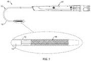
- FIG. 1is a side view of an example medical device system
- FIG. 2is a partial cross-sectional view of a portion of an example medical device delivery system
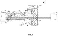
- FIG. 3is a partial cross-sectional view of a portion of an example medical device delivery system
- FIG. 4is a partial cross-sectional view of a portion of an example medical device delivery system
- FIG. 5is a partial cross-sectional view of a portion of an example medical device delivery system
- FIG. 5Ais a partial cross-sectional view of a portion of an example medical device delivery system along line 5 A- 5 A of FIG. 5 ;
- FIG. 5Bis a partial cross-sectional view of a portion of an example medical device delivery system
- FIG. 6is a partial cross-sectional view of a portion of an example medical device delivery system
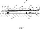
- FIG. 7is a partial cross-sectional view of a portion of an example medical device delivery system
- FIG. 8is a partial cross-sectional view of a portion of an example medical device delivery system.
- references in the specification to “an embodiment”, “some embodiments”, “other embodiments”, etc.indicate that the embodiment described may include one or more particular features, structures, and/or characteristics. However, such recitations do not necessarily mean that all embodiments include the particular features, structures, and/or characteristics. Additionally, when particular features, structures, and/or characteristics are described in connection with one embodiment, it should be understood that such features, structures, and/or characteristics may also be used connection with other embodiments whether or not explicitly described unless clearly stated to the contrary.
- Some relatively common medical conditionsmay include or be the result of inefficiency, ineffectiveness, or complete failure of one or more of the valves within the heart.
- failure of the aortic valve or the mitral valvecan have a serious effect on a human and could lead to serious health condition and/or death if not dealt with properly.
- Treatment of defective heart valvesposes other challenges in that the treatment often requires the repair or outright replacement of the defective valve.
- Such therapiesmay be highly invasive to the patient.
- medical devicesthat may be used for delivering a medical device to a portion of the cardiovascular system in order to diagnose, treat, and/or repair the system.
- At least some of the medical devices disclosed hereinmay be used to deliver and implant a replacement heart valve (e.g., a replacement aortic valve, replacement mitral valve, etc.).
- a replacement heart valvee.g., a replacement aortic valve, replacement mitral valve, etc.
- the devices disclosed hereinmay deliver the replacement heart valve percutaneously and, thus, may be much less invasive to the patient.
- the devices disclosed hereinmay also provide a number of additional desirable features and benefits as described in more detail below.
- a medical device system 10may be used to deliver and/or deploy a variety of medical devices to a number of locations within the anatomy.
- the medical device system 10may include a replacement heart valve delivery system (e.g., a replacement aortic valve delivery system) that can be used for percutaneous delivery of a medical implant 16 (shown in the detailed view of FIG. 1 ), such as a replacement/prosthetic heart valve.
- the medical device system 10may also be used for other interventions including valve repair, valvuloplasty, delivery of an implantable medical device (e.g., such as a stent, graft, etc.), and the like, or other similar interventions.
- an implantable medical devicee.g., such as a stent, graft, etc.
- the medical device system 10may generally be described as a catheter system that includes an outer sheath 12 , an inner catheter 14 extending at least partially through a lumen of the outer sheath 12 , and a medical implant 16 (e.g., a replacement heart valve implant) which may be coupled to the inner catheter 14 and disposed within a lumen of the outer sheath 12 during delivery of the medical implant 16 .
- a medical device handle 17may be disposed at a proximal end of the outer sheath 12 and/or the inner catheter 14 and may include one or more actuation mechanisms associated therewith.
- one or more tubular membersmay extend distally from the medical device handle 17 .
- the medical device handle 17may be designed to manipulate the position of the outer sheath 12 relative to the inner catheter 14 and/or aid in the deployment of the medical implant 16 .
- the outer sheath 12 of medical device system 12may include a curved portion 13 . While FIG. 1 shows the curve of the outer member 12 lying within the plane of the page, other configurations are contemplated. For example, configurations in which the curve of the outer member extends out of the page are contemplated.
- the medical device system 10may be advanced percutaneously through the vasculature to a position adjacent to an area of interest and/or a treatment location.
- the medical device system 10may be advanced through the vasculature to a position adjacent to a defective native valve (e.g., aortic valve, mitral valve, etc.).
- a defective native valvee.g., aortic valve, mitral valve, etc.
- Alternative approaches to treat a defective aortic valve and/or other heart valve(s)are also contemplated with the medical device system 10 .
- the medical implant 16may be generally disposed in an elongated and low profile “delivery” configuration within the lumen and/or a distal end of the outer sheath 12 , as seen schematically in FIG. 1 , for example.
- the outer sheath 12may be retracted relative to the medical implant 16 and/or the inner catheter 14 to expose the medical implant 16 .
- the medical implant 16may be self-expanding such that exposure of the medical implant 16 may deploy the medical implant 16 .
- the medical implant 16may be expanded/deployed using the medical device handle 17 in order to translate the medical implant 16 into a generally shortened and larger profile “deployed” configuration suitable for implantation within the anatomy.
- the medical device system 10may be disconnected, detached, and/or released from the medical implant 16 and the medical device system 10 can be removed from the vasculature, leaving the medical implant 16 in place in a “released” configuration.
- an implantable medical devicee.g., the medical implant 16
- portions of the medical device systeme.g., the medical device system 10
- components and design medical delivery systemse.g., such as the medical device system 10 and/or other medical devices
- reduce the profile of portions of the medical devicewhile maintaining sufficient strength (compressive, torsional, etc.) and flexibility of the system as a whole.
- FIG. 2illustrates the medical device system 10 in a partially deployed configuration.
- the outer sheath 12 of the medical device system 10has been retracted in a proximal direction to a position proximal of the medical implant 16 .
- the outer sheath 12has been retracted (e.g., pulled back) in a proximal direction such that it uncovers the medical device implant 16 from a compact, low-profile delivery position to a partially-deployed position.
- the medical device implant 16may be designed to self-expand once released from under the outer sheath 12 .
- the medical device system 10may be designed such that the implant 16 may be restricted from expanding fully in the radial direction.
- FIG. 2shows medical device implant 16 having a partially deployed position denoted as a length “L 1 .”
- FIG. 2further illustrates that in some examples, the implant 16 may include one or more support members 22 coupled to the proximal end 18 of the implant 16 . Further, FIG. 2 illustrates that in some examples, the implant 16 may include one or more translation members 24 coupled to the distal end 20 of the implant 16 . Additionally, in some examples (such as that illustrated in FIG. 2 ), the translation members 24 and support members 22 may work together to maintain the implant in a partially-deployed position after the outer sheath 12 has been retracted to uncover the implant 16 . For example, FIG.
- FIG. 2illustrates that the support members 22 may be designed such that the distal end of each of the support members 22 may be coupled to the proximal end of the implant 16 and that the proximal end of each of the support members 22 may be coupled to the distal end of the inner catheter 14 .
- FIG. 2illustrates that the proximal ends of the support members 22 may be attached to a containment fitting 29 which is rigidly fixed to the distal end of the inner catheter 14 .
- the support members 22may be designed to limit the proximal movement of the proximal end 18 of the implant 16 relative to the distal end of the inner catheter 14 .
- the translation members 24may be designed to translate in a distal-to-proximal direction such that the translation of the translation members (via operator manipulation at the handle, for example) may “pull” the distal end 20 of the implant closer to the proximal end 18 of the implant 16 .
- FIG. 3illustrates the distal-to-proximal translation of the translation members 24 .
- the implant 16may both foreshorten (along the longitudinal axis of the implant 16 ) and also expand radially outward.
- the foreshortening and radial expansion of implant 16can be seen by comparing the shape and position of the implant 16 in FIG. 2 to the shape and position of the implant 16 in FIG. 3 .
- the position of the implant 16 shown in FIG. 3may be described as a fully deployed positioned of the implant 16 (versus the partially deployed positioned of the implant 16 shown in FIG. 2 ).
- FIG. 3depicts the length of the fully deployed implant 16 as “L 2 ”, whereby the distance L 2 is less than the distance L 1 shown in FIG. 2 .
- the translation members 24may be designed to be able extend in a proximal-to-distal direction such that they elongate (e.g., lengthen) the implant 16 (along its longitudinal axis).
- the implant 16may be able to shift between a partially deployed position (shown in FIG. 2 ) and a fully deployed position (shown in FIG. 3 ) through the translation (either proximal or distal) of the translation members 24 along the longitudinal axis as the support members 22 limit the movement of the proximal end 18 of the implant 16 .
- an operatormay be able to manipulate the translation members 24 via the handle 17 .
- the handle 17may include an actuation member designed to control the translation of the translation members 24 .
- FIG. 2illustrates that the handle member 17 may be coupled to the translation members 24 via an actuation shaft 30 and a coupling member 28 . Additionally, FIG. 2 further illustrates that a distal end of actuation shaft 30 may be coupled to the proximal end of the coupling member 28 . Further, while not shown in FIG. 2 , it can be appreciated that the actuation shaft 30 may extend within the entire length of the inner catheter 14 from the coupling member 28 to the handle member 17 .
- the inner catheter 14may also be referred to as an inner member or liner 14 .
- the liner 14may include a number of different features shown in the figures described herein.
- the liner 14may include a lumen 25 .
- the translation members 24 , coupler 28 , actuation shaft 30 , tubular guidewire member 34 (described below), and grouping coil 32 (described below)may be disposed within the lumen 25 .
- the inner liner 14may vary in form.
- the inner liner 14may include a single lumen, multiple lumens, or lack a lumen.
- FIG. 2 and FIG. 3illustrate the translation of translation members 24 in a distal-to-proximal direction (which shortens and radially expands the implant 16 , as described above).
- FIG. 3further illustrates that translation of the translation members 24 in a distal-to-proximal direction is accomplished by translation of the actuation shaft 30 and coupling member 28 within the lumen 25 of the inner catheter 14 .
- the actuation shaft 30is retracted (e.g., pulled proximally within lumen 25 of the inner catheter 14 ), it retracts the coupling member 28 proximally, which, in turn, retracts the translation members 24 in a proximal direction.
- medical device system 10may include a component designed to limit and/or prevent the translation members 24 from twisting around each other within the lumen 25 of the inner catheter 14 .
- FIG. 2 and FIG. 3illustrate a grouping coil 32 wound around the translation members 24 such that the grouping coil 32 maintains the translation members 24 in a substantially liner configuration (and thereby limits and/or prevents the translation members 24 from twisting within lumen 25 ) as the translation members 24 are translated through the lumen 25 of the inner catheter 14 .
- FIG. 2 and FIG. 3further illustrate that the proximal end of the grouping coil 32 may be positioned adjacent the distal end of the coupling member 28 and that the distal end of the grouping coil 32 may be positioned adjacent the distal end of the inner catheter 14 .
- the distal end of the grouping coil 32may be prevented from extending distally beyond the distal end of the inner catheter 14 by the containment fitting 29 .
- the distal end of the grouping coil 32may contact the containment fitting 29 .
- the grouping coil 32may be positioned within the lumen 25 of the inner catheter 14 such that the grouping coil 32 may elongate and shorten (e.g., a length of the grouping coil may adjust) within the lumen 25 of the inner catheter 14 .
- the grouping coil 32may elongate while continuing to group and/or contain the translation members 24 in a substantially linear configuration.
- FIG. 2 and FIG. 3further illustrate that the medical device system 10 may include a tubular guidewire member 34 extending within the lumen 25 of the inner catheter 14 .
- the tubular guidewire member 34may include a lumen which permits a guidewire to extend and translate therein.
- the medical device system 10may be advanced to a target site within a body over a guidewire extending within the lumen of the tubular guidewire member 34 .
- the tubular guidewire member 34may extend from the handle member 17 , through the lumen 25 of the inner member 14 , through the implant 16 and terminate at a nosecone 36 .
- the inner catheter 14may include an exoskeleton 40 disposed along the outer surface of the inner catheter 14 .
- the exoskeleton 40may be positioned between the outer member 12 and the inner catheter 14 .
- the exoskeleton 40may be positioned between the inner surface of the outer member 12 and the outer surface of the inner catheter 14 .
- a distal end 42 of the exoskeleton 40may be rigidly fixed with respect to the end region 26 of the inner member 14 .
- the distal end 42 of the exoskeleton 40may be fixed directly to the inner member 14 .
- the exoskeleton 40may be attached to a fitting (not shown) which is fixed directly to the inner member 14 .
- a containment fitting 29(or other similar fitting) may be used to prevent the distal end 42 of the exoskeleton 40 from moving with respect to the end region 26 of inner member 14 .
- the exoskeleton 40may include a plurality of discrete members or articulating links.
- the exoskeleton 40may include a plurality of bead members 41 and a plurality of barrel members 43 .
- Other discrete membersare contemplated that may have differing shapes and/or configurations.
- the discrete memberse.g., the bead members 41 and the barrel members 43
- the bead members 41 and the barrel members 43may be arranged in a number of different configurations along the inner catheter 14 . In at least some instances, the bead members 41 and the barrel members 43 alternate along the inner catheter 14 . Other arrangements and/or patterns are contemplated.
- the outer member 12 , the inner shaft 14 (including the exoskeleton 40 ), the actuation shaft 30 (which is coupled to the translation members 24 ) and the tubular guidewire member 34may all extend from a position adjacent the medical implant 16 to a position in which they enter the handle member 17 .
- FIG. 4illustrates that the outer sheath 12 , the inner shaft 14 (including the exoskeleton 40 ), the actuation shaft 30 (which is coupled to the translation members 24 ) and the tubular guidewire member 34 may extend from an example medical implant 16 (which may be similar in form and function to the medical implant described above) and enter the distal end 45 of the handle member 17 .
- FIG. 4illustrates the inner member 14 may be rotated 90 degrees as compared to the inner member 14 shown in FIG. 2 and FIG. 3 . Further, rotation of the inner member 14 may also rotate the actuation shaft 30 and the tubular guidewire member 34 (positioned within lumen 25 of the inner member 14 ). For example, as shown in FIG. 4 , the actuation shaft 30 and the tubular guidewire member 34 have been rotated 90 degrees (as compared to their configuration shown in FIG. 2 and FIG. 3 ), and therefore, the tubular guidewire member 34 can be conceptualized as being positioned “behind” the actuation shaft 30 in the illustration.
- FIG. 4further illustrates that in some examples the exoskeleton 40 (described above) may further include a hypotube 44 positioned over inner member 14 .
- the hypotube 44may be aligned with the alternating bead 41 and barrel 43 members of the exoskeleton 40 .
- the alternating bead 41 and barrel 43 components of the exoskeleton 40may abut the hypotube 44 at a position which is distal to the distal end 45 of the handle member 17 .
- the transition from the bead 41 and barrel 43 components of the exoskeleton 40 to the hypotube 44may occur outside of handle member 17 .
- a distal end 46 of the hypotube 44may be positioned adjacent to a bead or barrel component 41 / 43 .
- the distal end 46 of hypotube 44may directly engage (e.g., contact) a bead or barrel component 41 / 43 of the exoskeleton 40 .
- the hypotube 44may extend into and terminate within the handle member 17 .
- actuation of the various componentsmay occur via a variety of actuation mechanisms disposed in handle member 17 .
- the actuation mechanismsmay function to move the various tubular components described above relative to one another.
- each individual actuation mechanismmay need to be fluidly sealed to prevent fluid leakage into portions thereof (including components residing therein) which may be damaged or contaminated by contact with fluid.
- FIG. 4illustrates an example fluid sealing assembly 50 .
- Fluid sealing assembly 50may include an outer sheath seal assembly 52 , a turnbuckle seal assembly 54 , an actuation member seal assembly 56 and a guidewire member seal assembly 58 , each of which will be described in greater detail below.
- Outer sheath seal assembly 52may include a luer lock flushing port 53 .
- the luer lock flushing port 53may include a check valve.
- each of the outer member 12 , the inner shaft 14 (including portions of the exoskeleton 40 ), the actuation shaft 30 and the tubular guidewire member 34may be coupled to one or more of the outer sheath seal assembly 52 , the turnbuckle seal assembly 54 , the actuation member seal assembly 56 and the guidewire member seal assembly 58 .
- FIG. 5illustrates an example outer sheath seal assembly 52 .
- outer sheath seal assembly 52may include a body 59 .
- body 59may include a post 48 extending along in a direction parallel to the longitudinal axis of the handle member 17 .
- the post 48may include a cavity 63 into which a proximal end of the outer member 12 may be inserted.
- the post 48 of body 59may include a threaded region 60 .
- Outer sheath seal assembly 52may be designed to seal the outer member 12 while providing a passageway for the inner shaft 14 , the hypotube 44 , the actuation shaft 30 and the tubular guidewire member 34 (not visible in FIG. 5 ) to extend therethrough.
- FIG. 5illustrates that the outer sheath seal assembly 52 may include an outer seal 51 .
- Outer seal 51may be an O-ring or other similar type seal.
- the outer seal 51may be positioned between an inner surface of the post 48 of the body 59 and the outer surface of the outer member 12 .
- the outer sheath seal assembly 52may include a seal nut 47 .
- Seal nut 47may include a threaded region 61 . It can be appreciated that the seal nut 47 may be designed to mate with the post 48 . For example, it can be appreciated that the seal nut 47 may be designed to thread onto (e.g., screw onto) the post 48 of the body 59 .
- FIG. 5further illustrates that in some examples, the outer member 12 may include a ferrule 49 which may be attached to the outer surface of the outer member 12 .
- the ferrule 49may be overmolded onto the outer surface of the outer member 12 .
- the profile of the outer surface of the ferrule 49may be designed to mate with a portion of the inner surface of the seal nut 47 .
- the seal nut 47 , the ferrule 49 , the post 48 and the outer seal 51may operate cooperatively to prevent fluid from leaking out of the outer sheath seal assembly 52 . Specifically, rotation of the seal nut 47 onto the post 48 may translate the ferrule 49 in a distal-to-proximal direction, thereby compressing the outer seal 51 onto the outer surface of the outer member 12 .
- FIG. 5further illustrates that the seal assembly 52 may include a threaded back-up ring 57 .
- the back-up ring 57may be threadably engaged with a mating threaded portion 62 of the body member 59 .
- Threaded back-up ring 57may be designed to compress a hypotube seal 55 onto the hypotube 44 .
- rotation of the back-up ring 57 onto the body 59may compress the hypotube seal 55 onto the outer surface of the hypotube 44 .
- the hypotube seal 55may be an X-ring type seal, however, other seal configurations are contemplated. Utilizing an X-ring seal design for the hypotube seal 55 may reduce frictional forces upon the hypotube 44 in instances when the hypotube 44 is translated through the hypotube seal 55 .
- the outer member 12may terminate within the outer sheath seal assembly 52 . Accordingly, it can be further appreciated that actuation of the outer sheath seal assembly 52 may actuate (e.g., shift, translate, move, etc.) the outer sheath 12 . While not expressly depicted in the figures, it can be appreciated that the handle 17 may include one or more actuation mechanisms designed to actuate the outer sealing assembly 52 , which may shift outer member 12 relative to the hypotube 44 , the inner member 14 , the actuation shaft 30 and the tubular guidewire member 34 . Actuation of the outer member 12 may uncover (e.g., partially deploy) the medical device 16 as described above.
- the outer member 12 of the medical device system 10may include one or more features which are designed to orient the outer member 12 with the handle 17 in a specific configuration.
- FIG. 5Aillustrates a cross-section of the body 59 of an example sealing assembly 52 , as discussed above.
- the body 59may be similar in form and function the body 59 discussed above.
- the post 48may include a cavity 63 designed to accept the proximal end of an example outer member 12 therein.
- the cavity 63may include an alignment recess 64 , which, along with the overall profile of the cavity 63 , is designed to align the curved portion 13 (shown in FIG.
- FIG. 5Bshows a cross-section of the proximal end region of an example outer member 12 .
- the outer member 12may include a rib 65 molded onto the outer surface of the outer member 12 . It can be appreciated that the rib 65 may be aligned with the curved portion 13 of outer member 12 . It can further be appreciated that the cross-sectional profile of the proximal end of the outer member 12 matches (e.g., mates with) the profile of cavity 63 (which includes alignment recess 64 ), discussed above.
- FIG. 6illustrates an example turnbuckle seal assembly 54 .
- the turnbuckle seal assembly 54may include a cap member 66 coupled to a stationary member 67 .
- Stationary member 67may fixed relative to the handle member 17 .
- the stationary member 67may include one or more features that engage with handle 17 , thereby preventing the stationary member 67 from moving with respect to the handle 17 .
- the cap member 66may include a distal end 71 and a proximal end 82 . Further, the cap member 66 may include a lumen 83 extending through a portion or the full length of the cap member 66 . Further, the stationary member 67 may include a distal end 68 and a proximal end 69 . As shown in FIG. 6 , the distal end 68 of the stationary member 67 may be inserted into the lumen 83 of the cap member 66 . Additionally, the stationary member 67 may include one or more threads which are designed to mate with one or more threads positioned within the lumen 83 of the cap member 66 .
- FIG. 6The engagement of the threaded portion of the stationary member 67 and the threaded portion of the cap member 66 is shown in FIG. 6 as a threaded region 84 .
- a threaded region 84The engagement of the threaded portion of the stationary member 67 and the threaded portion of the cap member 66 is shown in FIG. 6 as a threaded region 84 .
- the turnbuckle seal assembly 54may include a first turnbuckle seal 76 positioned between the cap member 66 and the stationary member 67 .
- the first turnbuckle seal 76may be an X-ring type seal, however, other seal configurations are contemplated.
- the distal region 68 of the stationary member 67may include one or more attachment fingers 70 .
- Attachment fingers 70may be coupled to a proximal end of the inner member 14 (the inner member 14 is shown in FIG. 6 extending into the lumen 83 of the cap member 66 ).
- the attachment fingers 70 of the stationary member 67may be engaged with a fitting 85 disposed along the proximal end of the inner member 14 .
- FIG. 6further illustrates that the hypotube 44 may extend into and terminate within the cap member 66 .
- the proximal end of the hypotube 44may include a hypotube fitting 75 .
- the hypotube fitting 75may be securely fixed to the proximal end of the hypotube 44 .
- FIG. 6shows that the hypotube fitting 75 may engage with a protrusion 74 extending radially inward from the surface of the cap member 66 .
- rotation of the cap member 66may translate the hypotube 44 in a proximal-to-distal direction.
- the translation of the hypotube 44 in a proximal-to-distal directionmay also translate the distal end 46 of the hypotube 44 (shown in the detailed view of FIG. 4 ).
- the distal end of the hypotube 44may be engaged with the bead and barrel components 41 / 43 of exoskeleton 40 .
- the distal end of the bead and barrel components 41 / 43may be fixed to the distal end region of inner member 14 (discussed above with respect to FIG. 4 ). Therefore, proximal-to-distal movement of the hypotube 44 (via rotation of the cap member 66 ) may compress the individual bead and barrel components 41 / 43 against one another along the outer surface of the inner member 14 .
- putting the exoskeleton 40 in compressionmay correspondingly place the inner member 14 (and components thereof) in tension.
- FIG. 6further illustrates that the actuation shaft 30 and the tubular guidewire member 34 (not shown, but understood as being positioned “behind” the actuation shaft 30 in the illustration) may enter the distal end 71 of the cap member 66 .
- FIG. 6illustrates the actuation shaft 30 and the tubular guidewire member 34 may engage and be coupled together via a coupling component 77 of the turnbuckle seal assembly 54 .
- the coupling component 77is designed to couple the actuation shaft 30 , the tubular guidewire member 34 and the actuation hypotube 78 together while permitting the tubular guidewire member 34 to extend through at least a portion of the actuation hypotube 78 .
- FIG. 6illustrates the tubular guidewire member 34 (depicted as dashed lines) extending within at least a portion of the actuation hypotube 78 (which is coupled to a proximal end of the coupling component 77 ).
- the distal region 71 of the turnbuckle sealing assembly 54may include a threaded back-up ring 72 .
- Back-up ring 72may be threadably engaged with a mating threaded portion (not shown in FIG. 6 ) of cap member 66 .
- Threaded back-up ring 72may be designed to compress a second turnbuckle seal 73 onto the hypotube 44 .
- rotation of the back-up ring 72may compress the second turnbuckle seal 73 onto the outer surface of the hypotube 44 .
- the second turnbuckle seal 73may be an X-ring type seal, however, other seal configurations are contemplated. Utilizing an X-ring seal design for the second turnbuckle seal 73 may reduce frictional forces upon the hypotube 44 in instances when the hypotube 44 is translated through the second turnbuckle seal 73 .
- the proximal region 69 of the stationary member 67may include a second threaded back-up ring 80 .
- the second back-up ring 80may be threadably engaged with a mating threaded portion (not shown in FIG. 6 ) of the stationary member 67 .
- Threaded back-up ring 80may be designed to compress a third turnbuckle seal 81 onto the actuation hypotube 78 .
- rotation of the back-up ring 80may compress the third turnbuckle seal 81 onto the outer surface of the actuation hypotube 78 .
- the third turnbuckle seal 81may be an X-ring type seal, however, other seal configurations are contemplated. Utilizing an X-ring seal design for the third turnbuckle seal 81 may reduce frictional forces upon the actuation hypotube 78 in instances when the actuation hypotube 78 is translated through the third turnbuckle seal 81 .
- FIG. 7illustrates the actuation member sealing assembly 56 .
- the actuation sealing assembly 56may include a block member 92 .
- the block member 92may include a distal end 93 , a proximal end 94 and a lumen 95 extending therethrough.
- the actuation hypotube 78may enter the lumen 95 at the distal end 93 of the block member 92 . Further, the actuation hypotube 78 may extend through the lumen 95 of block member 92 and terminates in a threaded back-up ring 86 .
- the back-up ring 86 utilized in the actuation member seal assembly 56may be threadably engaged with a mating threaded portion (not shown in FIG. 7 ) of block member 92 .
- the threaded back-up ring 86may be designed to compress a first actuation seal 87 onto the actuation hypotube 78 .
- rotation of the back-up ring 86may compress the first actuation seal 87 onto the outer surface of the actuation hypotube 78 .
- the first actuation seal 87may be an X-ring type seal, however, other seal configurations are contemplated. Utilizing an X-ring seal design for the first actuation seal 87 may reduce frictional forces upon the actuation hypotube 78 in instances when the actuation hypotube 78 is translated through the third turnbuckle seal 81 .
- the actuation hypotube 78may be coupled to the actuation shaft 30 and the tubular guidewire member 34 via coupling component 77 .
- the actuation shaft 30may be coupled via coupler 28 (shown in FIG. 2 and FIG. 3 ) to the translation members 24 while the tubular guidewire member 34 may be coupled to the nosecone 36 . Therefore, it can be appreciated that actuation of block member 92 (and, correspondingly, the actuation hypotube 78 which is also coupled to the coupling component 77 ) in a distal-to-proximal direction may actuate both the translation members 24 and the nosecone 36 in a distal-to-proximal direction. As discussed above, the distal-to-proximal movement of the translation members 24 may shift the implant 16 from its length “L 1 ” illustrated in FIG. 2 to its length “L 2 ” illustrated in FIG. 3 .
- the distal-to-proximal movement of the block member 92may be controlled via an actuation handle (not shown in FIG. 7 ).
- the actuation handlemay include a pawl spring (not shown) that may engage a plurality of teeth 89 positioned along an outer surface of block member 92 . Engagement of the pawl spring with the plurality of teeth 89 may permit the block member 92 to shift in a distal-to-proximal direction while also preventing the block member 92 from shifting in a proximal-to-distal direction.
- FIG. 7further illustrates that the actuation member sealing assembly 56 may further include a guidewire hypotube 90 .
- the guidewire hypotube 90may enter the lumen 95 of the block 92 at the distal end 93 of the block member 92 .
- the guidewire hypotube 90may be a stationary hypotube. In other words, in some examples the guidewire hypotube 90 may rigidly fixed relative (e.g., remain in a fixed position) relative to the block 92 and the handle member 17 .
- a second actuation seal 88may be positioned within the back-up ring 86 .
- the threaded back-up ring 86may be designed to compress the second actuation sealing 88 onto the proximal guidewire tube 90 .
- the guidewire hypotube 90may extend into a lumen (not shown in FIG. 7 ) of the actuation hypotube 78 . Therefore, it further be appreciated that as the block member 92 is actuated (as discussed above), the actuation hypotube 78 may travel along the outer surface of the guidewire hypotube 90 . Additionally, the tubular guidewire member 34 may terminate at a position within the lumen of the guidewire hypotube 90 . For example, FIG. 7 illustrates the tubular guidewire member 34 (depicted by dashed lines in FIG. 7 ) terminating in the lumen 96 of the guidewire hypotube 90 .
- FIG. 8illustrates the guidewire tubing sealing assembly 58 .
- the guidewire sealing assembly 58may include a threaded luer lock port 97 .
- the luer lock port 97may be rigidly fixed to the handle member 17 . Further, the luer lock port 97 may include a lumen 98 extending therethrough.
- the luer lock port 97may be attached to the proximal guidewire tube 90 , which extends distally from the block 92 of the actuation member seal assembly 56 , described above with respect to FIG. 7 .
- the proximal guidewire tube 90may be welded (e.g., hermetically welded) to a portion of the luer lock port 97 .
- FIG. 8illustrates the lumen 98 of the luer lock port 97 having a diameter depicted as “X.” It can be appreciated that in at least some examples, the diameter “X” may be designed to permit a guidewire to pass therethrough while also providing minimum clearance such that fluid is not permitted to pass therethrough. In other words, the clearance between the outer diameter of a guidewire (not shown) and the diameter “X” of the channel 99 may be designed to prevent fluid from leaking out of the luer lock port 97 .
- the materials that can be used for the various components of the medical devices and/or system 10 disclosed hereinmay include those commonly associated with medical devices. However, this is not intended to limit the devices and methods described herein, as the discussion may be applied to other components of the medical devices and/or systems 10 disclosed herein including the various shafts, liners, components described relative thereto.
- the medical device 10may be made from a metal, metal alloy, polymer (some examples of which are disclosed below), a metal-polymer composite, ceramics, combinations thereof, and the like, or other suitable material.
- suitable polymersmay include polytetrafluoroethylene (PTFE), ethylene tetrafluoroethylene (ETFE), fluorinated ethylene propylene (FEP), polyoxymethylene (POM, for example, DELRIN® available from DuPont), polyether block ester, polyurethane (for example, Polyurethane 85A), polypropylene (PP), polyvinylchloride (PVC), polyether-ester (for example, ARNITEL® available from DSM Engineering Plastics), ether or ester based copolymers (for example, butylene/poly(alkylene ether) phthalate and/or other polyester elastomers such as HYTREL® available from DuPont), polyamide (for example, DURETHAN® available from Bayer or CRISTAMID® available
- suitable metals and metal alloysinclude stainless steel, such as 304V, 304L, and 316LV stainless steel; mild steel; nickel-titanium alloy such as linear-elastic and/or super-elastic nitinol; other nickel alloys such as nickel-chromium-molybdenum alloys (e.g., UNS: N06625 such as INCONEL® 625, UNS: N06022 such as HASTELLOY® C-22®, UNS: N10276 such as HASTELLOY® C276®, other HASTELLOY® alloys, and the like), nickel-copper alloys (e.g., UNS: N04400 such as MONEL® 400, NICKELVAC® 400, NICORROS® 400, and the like), nickel-cobalt-chromium-molybdenum alloys (e.g., UNS: R30035 such as MP35-N® and the like), nickel-molybdenum alloys (e.g.,
- portions or all of the medical device 10may also be doped with, made of, or otherwise include a radiopaque material.
- Radiopaque materialsare understood to be materials capable of producing a relatively bright image on a fluoroscopy screen or another imaging technique during a medical procedure. This relatively bright image aids the user of the medical device 10 in determining its location.
- Some examples of radiopaque materialscan include, but are not limited to, gold, platinum, palladium, tantalum, tungsten alloy, polymer material loaded with a radiopaque filler, and the like. Additionally, other radiopaque marker bands and/or coils may also be incorporated into the design of the medical device 10 to achieve the same result.
- a degree of Magnetic Resonance Imaging (MRI) compatibilityis imparted into the medical device 10 .
- the medical device 10may include a material that does not substantially distort the image and create substantial artifacts (e.g., gaps in the image). Certain ferromagnetic materials, for example, may not be suitable because they may create artifacts in an MRI image.
- the medical device 10may also be made from a material that the MRI machine can image.
- Some materials that exhibit these characteristicsinclude, for example, tungsten, cobalt-chromium-molybdenum alloys (e.g., UNS: R30003 such as ELGILOY®, PHYNOX®, and the like), nickel-cobalt-chromium-molybdenum alloys (e.g., UNS: R30035 such as MP35-N® and the like), nitinol, and the like, and others.
- cobalt-chromium-molybdenum alloyse.g., UNS: R30003 such as ELGILOY®, PHYNOX®, and the like
- nickel-cobalt-chromium-molybdenum alloyse.g., UNS: R30035 such as MP35-N® and the like
- nitinoland the like, and others.
Landscapes
- Health & Medical Sciences (AREA)
- Life Sciences & Earth Sciences (AREA)
- Engineering & Computer Science (AREA)
- Biomedical Technology (AREA)
- Veterinary Medicine (AREA)
- Animal Behavior & Ethology (AREA)
- Heart & Thoracic Surgery (AREA)
- Public Health (AREA)
- General Health & Medical Sciences (AREA)
- Pulmonology (AREA)
- Biophysics (AREA)
- Anesthesiology (AREA)
- Hematology (AREA)
- Oral & Maxillofacial Surgery (AREA)
- Vascular Medicine (AREA)
- Cardiology (AREA)
- Transplantation (AREA)
- Prostheses (AREA)
- Media Introduction/Drainage Providing Device (AREA)
Abstract
Description
- a first actuating assembly, wherein the first actuating assembly is configured to receive a deployment sheath;
- a second actuating assembly, wherein the second actuating assembly is configured to receive an actuating shaft; and
- a turnbuckle assembly including a cap and a stationary member;
Claims (17)
Priority Applications (1)
| Application Number | Priority Date | Filing Date | Title |
|---|---|---|---|
| US15/969,817US11013889B2 (en) | 2017-05-03 | 2018-05-03 | Medical device with sealing assembly |
Applications Claiming Priority (2)
| Application Number | Priority Date | Filing Date | Title |
|---|---|---|---|
| US201762500990P | 2017-05-03 | 2017-05-03 | |
| US15/969,817US11013889B2 (en) | 2017-05-03 | 2018-05-03 | Medical device with sealing assembly |
Publications (2)
| Publication Number | Publication Date |
|---|---|
| US20180318546A1 US20180318546A1 (en) | 2018-11-08 |
| US11013889B2true US11013889B2 (en) | 2021-05-25 |
Family
ID=62563253
Family Applications (1)
| Application Number | Title | Priority Date | Filing Date |
|---|---|---|---|
| US15/969,817Active2039-03-17US11013889B2 (en) | 2017-05-03 | 2018-05-03 | Medical device with sealing assembly |
Country Status (5)
| Country | Link |
|---|---|
| US (1) | US11013889B2 (en) |
| EP (1) | EP3618776B1 (en) |
| JP (1) | JP6884884B2 (en) |
| CN (1) | CN110868965B (en) |
| WO (1) | WO2018204558A1 (en) |
Families Citing this family (6)
| Publication number | Priority date | Publication date | Assignee | Title |
|---|---|---|---|---|
| JP7114738B2 (en)* | 2018-04-26 | 2022-08-08 | ボストン サイエンティフィック サイムド,インコーポレイテッド | Medical device with connecting member |
| CN112334097B (en)* | 2018-04-26 | 2025-06-13 | 波士顿科学国际有限公司 | Medical device with telescopic sealing assembly |
| US11723767B2 (en) | 2019-08-15 | 2023-08-15 | Boston Scientific Scimed, Inc. | Medical device including attachable tip member |
| US12396852B2 (en) | 2021-01-26 | 2025-08-26 | Boston Scientific Scimed, Inc. | Medical device including attachable components |
| US12016777B2 (en) | 2021-01-26 | 2024-06-25 | Boston Scientific Scimed, Inc. | Medical device including attachable components |
| CN114711926B (en)* | 2022-06-08 | 2022-09-02 | 深圳佰特微医疗科技有限公司 | Sealing device and conveying system |
Citations (105)
| Publication number | Priority date | Publication date | Assignee | Title |
|---|---|---|---|---|
| US3674014A (en) | 1969-10-28 | 1972-07-04 | Astra Meditec Ab | Magnetically guidable catheter-tip and method |
| US4798598A (en) | 1986-05-23 | 1989-01-17 | Sarcem S.A. | Guide for a catheter |
| US4955384A (en) | 1989-05-11 | 1990-09-11 | Advanced Cardiovascular Systems, Inc. | Guiding member for vascular catheters with a flexible link distal section |
| US4985022A (en) | 1988-11-23 | 1991-01-15 | Med Institute, Inc. | Catheter having durable and flexible segments |
| US4998923A (en) | 1988-08-11 | 1991-03-12 | Advanced Cardiovascular Systems, Inc. | Steerable dilatation catheter |
| US5003989A (en) | 1989-05-11 | 1991-04-02 | Advanced Cardiovascular Systems, Inc. | Steerable dilation catheter |
| US5095915A (en) | 1990-03-19 | 1992-03-17 | Target Therapeutics | Guidewire with flexible distal tip |
| US5315996A (en) | 1991-02-15 | 1994-05-31 | Lundquist Ingemar H | Torquable catheter and method |
| US5406960A (en) | 1994-04-13 | 1995-04-18 | Cordis Corporation | Guidewire with integral core and marker bands |
| US5437288A (en) | 1992-09-04 | 1995-08-01 | Mayo Foundation For Medical Education And Research | Flexible catheter guidewire |
| US5570701A (en) | 1992-08-12 | 1996-11-05 | Scimed Life Systems, Inc. | Shaft movement control apparatus and method |
| EP0778040A2 (en) | 1995-12-07 | 1997-06-11 | Sarcos, Inc. | Hollow guide wire apparatus for catheters |
| US5746701A (en) | 1995-09-14 | 1998-05-05 | Medtronic, Inc. | Guidewire with non-tapered tip |
| US5749837A (en) | 1993-05-11 | 1998-05-12 | Target Therapeutics, Inc. | Enhanced lubricity guidewire |
| US5769796A (en) | 1993-05-11 | 1998-06-23 | Target Therapeutics, Inc. | Super-elastic composite guidewire |
| US5772609A (en) | 1993-05-11 | 1998-06-30 | Target Therapeutics, Inc. | Guidewire with variable flexibility due to polymeric coatings |
| US5776080A (en) | 1992-08-12 | 1998-07-07 | Scimed Life Systems, Inc. | Shaft movement control apparatus |
| US5902254A (en) | 1996-07-29 | 1999-05-11 | The Nemours Foundation | Cathether guidewire |
| US5931830A (en) | 1995-12-07 | 1999-08-03 | Sarcos L.C. | Hollow coil guide wire apparatus for catheters |
| US5951494A (en) | 1995-02-28 | 1999-09-14 | Boston Scientific Corporation | Polymeric implements for torque transmission |
| US5967984A (en)* | 1995-06-30 | 1999-10-19 | Boston Scientific Corporation | Ultrasound imaging catheter with a cutting element |
| US6001068A (en) | 1996-10-22 | 1999-12-14 | Terumo Kabushiki Kaisha | Guide wire having tubular connector with helical slits |
| US6017319A (en) | 1996-05-24 | 2000-01-25 | Precision Vascular Systems, Inc. | Hybrid tubular guide wire for catheters |
| US6139510A (en) | 1994-05-11 | 2000-10-31 | Target Therapeutics Inc. | Super elastic alloy guidewire |
| US6176856B1 (en)* | 1998-12-18 | 2001-01-23 | Eclipse Surgical Technologies, Inc | Resistive heating system and apparatus for improving blood flow in the heart |
| US6273876B1 (en) | 1997-12-05 | 2001-08-14 | Intratherapeutics, Inc. | Catheter segments having circumferential supports with axial projection |
| US20010037141A1 (en) | 1997-11-14 | 2001-11-01 | Yee Carl E. | Multi-sheath delivery catheter |
| US20030069521A1 (en) | 2001-10-05 | 2003-04-10 | Brian Reynolds | Composite guidewire |
| US6606921B2 (en) | 1995-09-19 | 2003-08-19 | Nobert Noetzold | Pull cable system |
| US6739787B1 (en) | 1999-04-30 | 2004-05-25 | Bystroem Johan Adolf | Joint device |
| US20040220499A1 (en) | 2003-05-01 | 2004-11-04 | Scimed Life Systems, Inc. | Medical instrument with controlled torque transmission |
| US20040243143A1 (en) | 2003-05-27 | 2004-12-02 | Corcoran Michael P. | Flexible delivery device |
| US20050080400A1 (en) | 2003-05-27 | 2005-04-14 | Cardia, Inc. | Flexible medical device |
| US20050090848A1 (en) | 2003-10-22 | 2005-04-28 | Adams Kenneth M. | Angled tissue cutting instruments and method of fabricating angled tissue cutting instruments having flexible inner tubular members of tube and sleeve construction |
| US20050267444A1 (en) | 2003-03-27 | 2005-12-01 | Stephen Griffin | Medical device |
| WO2006041612A2 (en) | 2004-10-08 | 2006-04-20 | Cardia, Inc. | Flexible center connection for occlusion device |
| US20060111615A1 (en) | 2004-11-23 | 2006-05-25 | Novare Surgical Systems, Inc. | Articulating sheath for flexible instruments |
| US7055656B2 (en) | 2003-04-25 | 2006-06-06 | Delta Cycle Corporation | Apparatus for restraining cable curvature |
| US20060122537A1 (en) | 2001-10-05 | 2006-06-08 | Brian Reynolds | Composite guidewire |
| WO2006073581A2 (en) | 2004-11-23 | 2006-07-13 | Novare Surgical Systems, Inc. | Articulating mechanisms and link systems with torque transmission in remote manipulation of instruments and tools |
| US20060179966A1 (en) | 2005-02-03 | 2006-08-17 | Kuo Yung-Pin | Flexible sheath for cables |
| US20060189896A1 (en) | 1995-12-07 | 2006-08-24 | Davis Clark C | Medical device with collapse-resistant liner and mehtod of making same |
| US20070066900A1 (en) | 2005-09-22 | 2007-03-22 | Boston Scientific Scimed, Inc. | Intravascular ultrasound catheter |
| US20070083132A1 (en) | 2005-10-11 | 2007-04-12 | Sharrow James S | Medical device coil |
| US20070100285A1 (en) | 2005-10-27 | 2007-05-03 | Boston Scientific Scimed, Inc. | Elongate medical device with continuous reinforcement member |
| US20070114211A1 (en) | 2003-02-26 | 2007-05-24 | Boston Scientific Scimed, Inc. | Elongated medical device with distal cap |
| US20070213812A1 (en)* | 2002-11-15 | 2007-09-13 | Webler William E | Apparatuses and methods for delivering/deploying a medical device in a vessel |
| US20070233043A1 (en) | 2006-03-31 | 2007-10-04 | Boston Scientific Scimed, Inc. | Flexible device shaft with angled spiral wrap |
| US20080064989A1 (en) | 2006-09-13 | 2008-03-13 | Boston Scientific Scimed, Inc. | Crossing guidewire |
| US20080077119A1 (en) | 2001-07-05 | 2008-03-27 | Precision Vascular Systems, Inc. | Torqueable soft tip medical device and method of usage |
| US20080194994A1 (en) | 2007-02-08 | 2008-08-14 | C.R. Bard, Inc. | Shape memory medical device and methods of use |
| US20080205980A1 (en) | 2007-02-27 | 2008-08-28 | Carnegie Mellon University | System for releasably attaching a disposable device to a durable device |
| US20080262474A1 (en) | 2007-04-20 | 2008-10-23 | Boston Scientific Scimed, Inc. | Medical device |
| US20090036833A1 (en) | 2007-08-02 | 2009-02-05 | Boston Scientific Scimed, Inc. | Composite elongate medical device including distal tubular member |
| US20090043228A1 (en) | 2007-08-06 | 2009-02-12 | Boston Scientific Scimed, Inc. | Laser shock peening of medical devices |
| US20090043283A1 (en) | 2007-08-07 | 2009-02-12 | Boston Scientific Scimed, Inc. | Microfabricated catheter with improved bonding structure |
| US7533906B2 (en) | 2003-10-14 | 2009-05-19 | Water Pik, Inc. | Rotatable and pivotable connector |
| US20090143768A1 (en) | 2007-04-23 | 2009-06-04 | Interventional & Surgical Innovations, Llc | Guidewire with adjustable stiffness |
| US20090156999A1 (en) | 2007-12-13 | 2009-06-18 | Boston Scientific Scimed, Inc. | Coil member for a medical device |
| US20090171151A1 (en) | 2004-06-25 | 2009-07-02 | Choset Howard M | Steerable, follow the leader device |
| US20100063480A1 (en) | 2008-09-10 | 2010-03-11 | Boston Scientific Scimed, Inc. | Medical devices and tapered tubular members for use in medical devices |
| US20100076266A1 (en) | 2003-04-01 | 2010-03-25 | Boston Scientific Scimed, Inc | Articulation joint for video endoscope |
| US20100080892A1 (en) | 2008-09-30 | 2010-04-01 | O'brien Michael J | Varnish compositions for electrical insulation and method of using the same |
| US20100145308A1 (en) | 2008-12-10 | 2010-06-10 | Boston Scientific Scimed, Inc. | Medical devices with a slotted tubular member having improved stress distribution |
| US7784376B2 (en) | 2007-09-14 | 2010-08-31 | Chun-Te Wen | Bicycle cable assembly |
| US20100249655A1 (en) | 2009-03-30 | 2010-09-30 | C. R. Bard, Inc. | Tip-Shapeable Guidewire |
| US7824345B2 (en) | 2003-12-22 | 2010-11-02 | Boston Scientific Scimed, Inc. | Medical device with push force limiter |
| US20100286566A1 (en) | 2003-05-27 | 2010-11-11 | Boston Scientific Scimed, Inc. | Medical device having segmented construction |
| US20100294071A1 (en) | 2006-10-24 | 2010-11-25 | Carnegie Mellon University | Steerable multi-linked device having a modular link assembly |
| US7841994B2 (en) | 2007-11-02 | 2010-11-30 | Boston Scientific Scimed, Inc. | Medical device for crossing an occlusion in a vessel |
| US20100305475A1 (en) | 2007-04-23 | 2010-12-02 | Hinchliffe Peter W J | Guidewire with adjustable stiffness |
| US7914467B2 (en) | 2002-07-25 | 2011-03-29 | Boston Scientific Scimed, Inc. | Tubular member having tapered transition for use in a medical device |
| US20110152613A1 (en) | 2008-04-14 | 2011-06-23 | Carnegie Mellon University | Articulated device with visualization system |
| US20110178588A1 (en) | 2008-09-05 | 2011-07-21 | Kenneth Haselby | Apparatus and methods for improved stent deployment |
| US20110184241A1 (en) | 2008-06-05 | 2011-07-28 | Cardiorobotics, Inc. | Extendable articulated probe device |
| US20110257478A1 (en) | 2010-04-20 | 2011-10-20 | Spinewindow Llc | Method and apparatus for performing retro peritoneal dissection |
| WO2011133486A1 (en) | 2010-04-19 | 2011-10-27 | Micrus Endovascular Llc | Low profile guiding catheter for neurovascular applications |
| US20110264191A1 (en) | 2010-04-23 | 2011-10-27 | Medtronic, Inc. | Delivery Systems and Methods of Implantation for Prosthetic Heart Valves |
| US8048004B2 (en) | 2002-07-25 | 2011-11-01 | Precision Vascular Systems, Inc. | Medical device for navigation through anatomy and method of making same |
| US8047236B2 (en) | 2008-09-12 | 2011-11-01 | Boston Scientific Scimed, Inc. | Flexible conduit with locking element |
| US8105246B2 (en) | 2007-08-03 | 2012-01-31 | Boston Scientific Scimed, Inc. | Elongate medical device having enhanced torque and methods thereof |
| US8137293B2 (en) | 2009-11-17 | 2012-03-20 | Boston Scientific Scimed, Inc. | Guidewires including a porous nickel-titanium alloy |
| EP2455128A2 (en) | 2010-11-18 | 2012-05-23 | Cook Medical Technologies LLC | Introducer assembly and sheath therefor |
| US8192422B2 (en) | 2006-08-14 | 2012-06-05 | Medrobotics Corporation | Steerable multi linked device having multiple working ports |
| US8197419B2 (en) | 2008-05-30 | 2012-06-12 | Inrad, Inc. | Biopsy device having specimen length adjustment |
| US20120160537A1 (en) | 2010-12-28 | 2012-06-28 | Wen Yuan-Hung | Cable sheath |
| US8376865B2 (en) | 2006-06-20 | 2013-02-19 | Cardiacmd, Inc. | Torque shaft and torque shaft drive |
| US8377035B2 (en) | 2003-01-17 | 2013-02-19 | Boston Scientific Scimed, Inc. | Unbalanced reinforcement members for medical device |
| US8376961B2 (en) | 2008-04-07 | 2013-02-19 | Boston Scientific Scimed, Inc. | Micromachined composite guidewire structure with anisotropic bending properties |
| US20130123912A1 (en) | 2011-11-15 | 2013-05-16 | Boston Scientific Scimed, Inc. | Medical device with nosecone and nosecone tube extension |
| US20130123796A1 (en) | 2011-11-15 | 2013-05-16 | Boston Scientific Scimed, Inc. | Medical device with keyed locking structures |
| US8475366B2 (en) | 2003-04-01 | 2013-07-02 | Boston Scientific Scimed, Inc. | Articulation joint for a medical device |
| US8535219B2 (en) | 2003-04-01 | 2013-09-17 | Boston Scientific Scimed, Inc. | Fluid manifold for endoscope system |
| US8551021B2 (en) | 2010-03-31 | 2013-10-08 | Boston Scientific Scimed, Inc. | Guidewire with an improved flexural rigidity profile |
| US8556914B2 (en) | 2006-12-15 | 2013-10-15 | Boston Scientific Scimed, Inc. | Medical device including structure for crossing an occlusion in a vessel |
| US8608648B2 (en) | 2003-04-01 | 2013-12-17 | Boston Scientific Scimed, Inc. | Articulation joint |
| US8622894B2 (en) | 2003-04-01 | 2014-01-07 | Boston Scientific Scimed, Inc. | Articulation joint |
| US8795202B2 (en) | 2011-02-04 | 2014-08-05 | Boston Scientific Scimed, Inc. | Guidewires and methods for making and using the same |
| US20140235361A1 (en) | 2013-02-15 | 2014-08-21 | Cardiacmd, Inc. | Torque Shaft and Torque Shaft Drive |
| US8821477B2 (en) | 2007-08-06 | 2014-09-02 | Boston Scientific Scimed, Inc. | Alternative micromachined structures |
| US9072874B2 (en) | 2011-05-13 | 2015-07-07 | Boston Scientific Scimed, Inc. | Medical devices with a heat transfer region and a heat sink region and methods for manufacturing medical devices |
| US9370432B2 (en) | 2010-12-10 | 2016-06-21 | Globus Medical, Inc. | Spine stabilization device and methods |
| US9402682B2 (en) | 2010-09-24 | 2016-08-02 | Ethicon Endo-Surgery, Llc | Articulation joint features for articulating surgical device |
| US20160317301A1 (en) | 2015-04-30 | 2016-11-03 | Edwards Lifesciences Cardiaq Llc | Replacement mitral valve, delivery system for replacement mitral valve and methods of use |
| US20180140323A1 (en) | 2016-11-22 | 2018-05-24 | Boston Scientific Scimed, Inc. | Medical device shaft resistant to compression and/or tension |
Family Cites Families (7)
| Publication number | Priority date | Publication date | Assignee | Title |
|---|---|---|---|---|
| US7632285B2 (en)* | 2005-05-03 | 2009-12-15 | Ethicon Endo-Surgery, Inc. | Sheath for enabling insertion and extraction of anastomotic ring applier |
| US20070208405A1 (en)* | 2006-03-06 | 2007-09-06 | Boston Scientific Scimed, Inc. | Stent delivery catheter |
| US7892276B2 (en)* | 2007-12-21 | 2011-02-22 | Boston Scientific Scimed, Inc. | Valve with delayed leaflet deployment |
| EP2651347B1 (en)* | 2010-12-13 | 2021-06-30 | Microvention, Inc. | Stent |
| CA3100305A1 (en)* | 2011-12-19 | 2013-06-27 | Coloplast A/S | A luminal prosthesis and a gastrointestinal implant device |
| EP2967950A1 (en)* | 2013-03-12 | 2016-01-20 | Abbott Cardiovascular Systems Inc. | Catheter having movable tubular structure and proximal stopper |
| US9901444B2 (en)* | 2013-12-17 | 2018-02-27 | Edwards Lifesciences Corporation | Inverted valve structure |
- 2018
- 2018-05-03JPJP2019559780Apatent/JP6884884B2/ennot_activeExpired - Fee Related
- 2018-05-03EPEP18730169.2Apatent/EP3618776B1/enactiveActive
- 2018-05-03WOPCT/US2018/030751patent/WO2018204558A1/ennot_activeCeased
- 2018-05-03USUS15/969,817patent/US11013889B2/enactiveActive
- 2018-05-03CNCN201880044610.8Apatent/CN110868965B/ennot_activeExpired - Fee Related
Patent Citations (175)
| Publication number | Priority date | Publication date | Assignee | Title |
|---|---|---|---|---|
| US3674014A (en) | 1969-10-28 | 1972-07-04 | Astra Meditec Ab | Magnetically guidable catheter-tip and method |
| US4798598A (en) | 1986-05-23 | 1989-01-17 | Sarcem S.A. | Guide for a catheter |
| US4998923A (en) | 1988-08-11 | 1991-03-12 | Advanced Cardiovascular Systems, Inc. | Steerable dilatation catheter |
| US4985022A (en) | 1988-11-23 | 1991-01-15 | Med Institute, Inc. | Catheter having durable and flexible segments |
| US4955384A (en) | 1989-05-11 | 1990-09-11 | Advanced Cardiovascular Systems, Inc. | Guiding member for vascular catheters with a flexible link distal section |
| US5003989A (en) | 1989-05-11 | 1991-04-02 | Advanced Cardiovascular Systems, Inc. | Steerable dilation catheter |
| US5095915A (en) | 1990-03-19 | 1992-03-17 | Target Therapeutics | Guidewire with flexible distal tip |
| US5599492A (en) | 1990-03-19 | 1997-02-04 | Target Therapeutics, Inc. | Method for making a guidewire with a flexible distal tip |
| US5315996A (en) | 1991-02-15 | 1994-05-31 | Lundquist Ingemar H | Torquable catheter and method |
| US5776080A (en) | 1992-08-12 | 1998-07-07 | Scimed Life Systems, Inc. | Shaft movement control apparatus |
| US5570701A (en) | 1992-08-12 | 1996-11-05 | Scimed Life Systems, Inc. | Shaft movement control apparatus and method |
| US5437288A (en) | 1992-09-04 | 1995-08-01 | Mayo Foundation For Medical Education And Research | Flexible catheter guidewire |
| US5749837A (en) | 1993-05-11 | 1998-05-12 | Target Therapeutics, Inc. | Enhanced lubricity guidewire |
| US5769796A (en) | 1993-05-11 | 1998-06-23 | Target Therapeutics, Inc. | Super-elastic composite guidewire |
| US5772609A (en) | 1993-05-11 | 1998-06-30 | Target Therapeutics, Inc. | Guidewire with variable flexibility due to polymeric coatings |
| US5406960A (en) | 1994-04-13 | 1995-04-18 | Cordis Corporation | Guidewire with integral core and marker bands |
| US6139510A (en) | 1994-05-11 | 2000-10-31 | Target Therapeutics Inc. | Super elastic alloy guidewire |
| US5951494A (en) | 1995-02-28 | 1999-09-14 | Boston Scientific Corporation | Polymeric implements for torque transmission |
| US5967984A (en)* | 1995-06-30 | 1999-10-19 | Boston Scientific Corporation | Ultrasound imaging catheter with a cutting element |
| US5746701A (en) | 1995-09-14 | 1998-05-05 | Medtronic, Inc. | Guidewire with non-tapered tip |
| US6606921B2 (en) | 1995-09-19 | 2003-08-19 | Nobert Noetzold | Pull cable system |
| US5833632A (en) | 1995-12-07 | 1998-11-10 | Sarcos, Inc. | Hollow guide wire apparatus catheters |
| US5931830A (en) | 1995-12-07 | 1999-08-03 | Sarcos L.C. | Hollow coil guide wire apparatus for catheters |
| EP0778040A2 (en) | 1995-12-07 | 1997-06-11 | Sarcos, Inc. | Hollow guide wire apparatus for catheters |
| US20060189896A1 (en) | 1995-12-07 | 2006-08-24 | Davis Clark C | Medical device with collapse-resistant liner and mehtod of making same |
| US7914466B2 (en) | 1995-12-07 | 2011-03-29 | Precision Vascular Systems, Inc. | Medical device with collapse-resistant liner and method of making same |
| US6017319A (en) | 1996-05-24 | 2000-01-25 | Precision Vascular Systems, Inc. | Hybrid tubular guide wire for catheters |
| US5902254A (en) | 1996-07-29 | 1999-05-11 | The Nemours Foundation | Cathether guidewire |
| US6001068A (en) | 1996-10-22 | 1999-12-14 | Terumo Kabushiki Kaisha | Guide wire having tubular connector with helical slits |
| US20010037141A1 (en) | 1997-11-14 | 2001-11-01 | Yee Carl E. | Multi-sheath delivery catheter |
| US6273876B1 (en) | 1997-12-05 | 2001-08-14 | Intratherapeutics, Inc. | Catheter segments having circumferential supports with axial projection |
| US6176856B1 (en)* | 1998-12-18 | 2001-01-23 | Eclipse Surgical Technologies, Inc | Resistive heating system and apparatus for improving blood flow in the heart |
| US6739787B1 (en) | 1999-04-30 | 2004-05-25 | Bystroem Johan Adolf | Joint device |
| US8449526B2 (en) | 2001-07-05 | 2013-05-28 | Boston Scientific Scimed, Inc. | Torqueable soft tip medical device and method of usage |
| US20080077119A1 (en) | 2001-07-05 | 2008-03-27 | Precision Vascular Systems, Inc. | Torqueable soft tip medical device and method of usage |
| US20070244414A1 (en) | 2001-10-05 | 2007-10-18 | Boston Scientific Scimed, Inc. | Composite guidewire |
| US7074197B2 (en) | 2001-10-05 | 2006-07-11 | Scimed Life Systems, Inc. | Composite guidewire |
| US6918882B2 (en) | 2001-10-05 | 2005-07-19 | Scimed Life Systems, Inc. | Guidewire with stiffness blending connection |
| US7993286B2 (en) | 2001-10-05 | 2011-08-09 | Boston Scientific Scimed, Inc. | Composite guidewire |
| US20070135734A1 (en) | 2001-10-05 | 2007-06-14 | Boston Scientific Scimed, Inc. | Composite guidewire |
| US20030069521A1 (en) | 2001-10-05 | 2003-04-10 | Brian Reynolds | Composite guidewire |
| US20030069520A1 (en) | 2001-10-05 | 2003-04-10 | Scimed Life Systems, Inc. | Guidewire with stiffness blending connection |
| US7618379B2 (en) | 2001-10-05 | 2009-11-17 | Boston Scientific Scimed, Inc. | Composite guidewire |
| US20060122537A1 (en) | 2001-10-05 | 2006-06-08 | Brian Reynolds | Composite guidewire |
| US8414506B2 (en) | 2001-10-05 | 2013-04-09 | Boston Scientific Scimed, Inc. | Composite guidewire |
| US8870790B2 (en) | 2002-07-25 | 2014-10-28 | Boston Scientific Scimed, Inc. | Medical device for navigation through anatomy and method of making same |
| US8900163B2 (en) | 2002-07-25 | 2014-12-02 | Precision Vascular Systems, Inc. | Medical device for navigation through anatomy and method of making same |
| US8048004B2 (en) | 2002-07-25 | 2011-11-01 | Precision Vascular Systems, Inc. | Medical device for navigation through anatomy and method of making same |
| US8915865B2 (en) | 2002-07-25 | 2014-12-23 | Precision Vascular Systems, Inc. | Medical device for navigation through anatomy and method of making same |
| US8932235B2 (en) | 2002-07-25 | 2015-01-13 | Precision Vascular Systems, Inc. | Medical device for navigation through anatomy and method of making same |
| US8936558B2 (en) | 2002-07-25 | 2015-01-20 | Precision Vascular Systems, Inc. | Medical device for navigation through anatomy and method of making same |
| US8939916B2 (en) | 2002-07-25 | 2015-01-27 | Precision Vascular Systems, Inc. | Medical device for navigation through anatomy and method of making same |
| US8257279B2 (en) | 2002-07-25 | 2012-09-04 | Boston Scientific Scimed, Inc. | Medical device for navigation through anatomy and method of making same |
| US7914467B2 (en) | 2002-07-25 | 2011-03-29 | Boston Scientific Scimed, Inc. | Tubular member having tapered transition for use in a medical device |
| US20070213812A1 (en)* | 2002-11-15 | 2007-09-13 | Webler William E | Apparatuses and methods for delivering/deploying a medical device in a vessel |
| US8377035B2 (en) | 2003-01-17 | 2013-02-19 | Boston Scientific Scimed, Inc. | Unbalanced reinforcement members for medical device |
| US20070114211A1 (en) | 2003-02-26 | 2007-05-24 | Boston Scientific Scimed, Inc. | Elongated medical device with distal cap |
| US8022331B2 (en) | 2003-02-26 | 2011-09-20 | Boston Scientific Scimed, Inc. | Method of making elongated medical devices |
| US20050267444A1 (en) | 2003-03-27 | 2005-12-01 | Stephen Griffin | Medical device |
| US8182465B2 (en) | 2003-03-27 | 2012-05-22 | Boston Scientific Scimed, Inc. | Medical device |
| US8636716B2 (en) | 2003-03-27 | 2014-01-28 | Boston Scientific Scimed, Inc. | Medical device |
| US8048060B2 (en) | 2003-03-27 | 2011-11-01 | Boston Scientific Scimed, Inc. | Medical device |
| US7540865B2 (en) | 2003-03-27 | 2009-06-02 | Boston Scientific Scimed, Inc. | Medical device |
| US9023011B2 (en) | 2003-03-27 | 2015-05-05 | Boston Scientific Scimed, Inc. | Medical device |
| US20070049902A1 (en) | 2003-03-27 | 2007-03-01 | Stephen Griffin | Medical device |
| US8608648B2 (en) | 2003-04-01 | 2013-12-17 | Boston Scientific Scimed, Inc. | Articulation joint |
| US8475366B2 (en) | 2003-04-01 | 2013-07-02 | Boston Scientific Scimed, Inc. | Articulation joint for a medical device |
| US8425408B2 (en) | 2003-04-01 | 2013-04-23 | Boston Scientific Scimed, Inc. | Articulation joint for video endoscope |
| US8535219B2 (en) | 2003-04-01 | 2013-09-17 | Boston Scientific Scimed, Inc. | Fluid manifold for endoscope system |
| US8622894B2 (en) | 2003-04-01 | 2014-01-07 | Boston Scientific Scimed, Inc. | Articulation joint |
| US20100076266A1 (en) | 2003-04-01 | 2010-03-25 | Boston Scientific Scimed, Inc | Articulation joint for video endoscope |
| US7055656B2 (en) | 2003-04-25 | 2006-06-06 | Delta Cycle Corporation | Apparatus for restraining cable curvature |
| US8292829B2 (en) | 2003-05-01 | 2012-10-23 | Boston Scientific Scimed, Inc. | Medical instrument with controlled torque transmission |
| US8845552B2 (en) | 2003-05-01 | 2014-09-30 | Boston Scientific Scimed, Inc. | Medical instrument with controlled torque transmission |
| US20040220499A1 (en) | 2003-05-01 | 2004-11-04 | Scimed Life Systems, Inc. | Medical instrument with controlled torque transmission |
| US7780611B2 (en) | 2003-05-01 | 2010-08-24 | Boston Scientific Scimed, Inc. | Medical instrument with controlled torque transmission |
| US6921397B2 (en) | 2003-05-27 | 2005-07-26 | Cardia, Inc. | Flexible delivery device |
| US7413563B2 (en) | 2003-05-27 | 2008-08-19 | Cardia, Inc. | Flexible medical device |
| US7625364B2 (en) | 2003-05-27 | 2009-12-01 | Cardia, Inc. | Flexible center connection for occlusion device |
| US20040243143A1 (en) | 2003-05-27 | 2004-12-02 | Corcoran Michael P. | Flexible delivery device |
| US20050080400A1 (en) | 2003-05-27 | 2005-04-14 | Cardia, Inc. | Flexible medical device |
| US8485992B2 (en) | 2003-05-27 | 2013-07-16 | Boston Scientific Scimed, Inc. | Medical device having segmented construction |
| US20100286566A1 (en) | 2003-05-27 | 2010-11-11 | Boston Scientific Scimed, Inc. | Medical device having segmented construction |
| US7533906B2 (en) | 2003-10-14 | 2009-05-19 | Water Pik, Inc. | Rotatable and pivotable connector |
| US7338495B2 (en) | 2003-10-22 | 2008-03-04 | Medtronic Xomed, Inc. | Angled tissue cutting instruments having flexible inner tubular members of tube and sleeve construction |
| US20050090848A1 (en) | 2003-10-22 | 2005-04-28 | Adams Kenneth M. | Angled tissue cutting instruments and method of fabricating angled tissue cutting instruments having flexible inner tubular members of tube and sleeve construction |
| US7824345B2 (en) | 2003-12-22 | 2010-11-02 | Boston Scientific Scimed, Inc. | Medical device with push force limiter |
| US20090171151A1 (en) | 2004-06-25 | 2009-07-02 | Choset Howard M | Steerable, follow the leader device |
| US9011318B2 (en) | 2004-06-25 | 2015-04-21 | Carnegie Mellon University and University of Pittsburg—Of the Commonwealth System of Higher Education | Steerable, follow the leader device |
| WO2006041612A2 (en) | 2004-10-08 | 2006-04-20 | Cardia, Inc. | Flexible center connection for occlusion device |
| WO2006073581A2 (en) | 2004-11-23 | 2006-07-13 | Novare Surgical Systems, Inc. | Articulating mechanisms and link systems with torque transmission in remote manipulation of instruments and tools |
| US20060111615A1 (en) | 2004-11-23 | 2006-05-25 | Novare Surgical Systems, Inc. | Articulating sheath for flexible instruments |
| US20060179966A1 (en) | 2005-02-03 | 2006-08-17 | Kuo Yung-Pin | Flexible sheath for cables |
| US20070066900A1 (en) | 2005-09-22 | 2007-03-22 | Boston Scientific Scimed, Inc. | Intravascular ultrasound catheter |
| US20070083132A1 (en) | 2005-10-11 | 2007-04-12 | Sharrow James S | Medical device coil |
| US20070100285A1 (en) | 2005-10-27 | 2007-05-03 | Boston Scientific Scimed, Inc. | Elongate medical device with continuous reinforcement member |
| US8231551B2 (en) | 2005-10-27 | 2012-07-31 | Boston Scientific Scimed, Inc. | Elongate medical device with continuous reinforcement member |
| US20110082443A1 (en) | 2005-10-27 | 2011-04-07 | Boston Scientific Scimed, Inc. | Elongate Medical Device with Continuous Reinforcement Member |
| US7850623B2 (en) | 2005-10-27 | 2010-12-14 | Boston Scientific Scimed, Inc. | Elongate medical device with continuous reinforcement member |
| US7579550B2 (en) | 2006-03-31 | 2009-08-25 | Boston Scientific Scimed, Inc. | Flexible device shaft with angled spiral wrap |
| US8677602B2 (en) | 2006-03-31 | 2014-03-25 | Boston Scientific Scimed, Inc. | Method of making a flexible device shaft with angled spiral wrap |
| US20090312606A1 (en) | 2006-03-31 | 2009-12-17 | Boston Scientific Scimed, Inc. | Flexible device shaft with angled spiral wrap |
| US20070233043A1 (en) | 2006-03-31 | 2007-10-04 | Boston Scientific Scimed, Inc. | Flexible device shaft with angled spiral wrap |
| US8124876B2 (en) | 2006-03-31 | 2012-02-28 | Boston Scientific Scimed, Inc. | Flexible device shaft with angled spiral wrap |
| US8376865B2 (en) | 2006-06-20 | 2013-02-19 | Cardiacmd, Inc. | Torque shaft and torque shaft drive |
| US9386911B2 (en) | 2006-08-14 | 2016-07-12 | Carnegie Mellon University | Steerable multi-linked device having multiple working ports |
| JP5575840B2 (en) | 2006-08-14 | 2014-08-20 | メドロボティクス コーポレーション | Operatable articulated device having a plurality of work ports |
| US8192422B2 (en) | 2006-08-14 | 2012-06-05 | Medrobotics Corporation | Steerable multi linked device having multiple working ports |
| US8317777B2 (en) | 2006-08-14 | 2012-11-27 | Medrobotics Corporation | Steerable multi-linked device having multiple working ports |
| US20080064989A1 (en) | 2006-09-13 | 2008-03-13 | Boston Scientific Scimed, Inc. | Crossing guidewire |
| US8551020B2 (en) | 2006-09-13 | 2013-10-08 | Boston Scientific Scimed, Inc. | Crossing guidewire |
| US20100294071A1 (en) | 2006-10-24 | 2010-11-25 | Carnegie Mellon University | Steerable multi-linked device having a modular link assembly |
| US8397481B2 (en) | 2006-10-24 | 2013-03-19 | Carnegie Mellon University | Steerable multi-linked device having a modular link assembly |
| US8656697B2 (en) | 2006-10-24 | 2014-02-25 | Carnegie Mellon University | Steerable multi-linked device having a modular link assembly |
| US7854109B2 (en) | 2006-10-24 | 2010-12-21 | Carnegie Mellon University | Steerable multi-linked device having a modular link assembly |
| US20110056320A1 (en) | 2006-10-24 | 2011-03-10 | Carnegie Mellon University | Steerable multi-linked device having a modular link assembly |
| US8099939B2 (en) | 2006-10-24 | 2012-01-24 | Carnegie Mellon University | Steerable multi-linked device having a modular link assembly |
| US7918080B2 (en) | 2006-10-24 | 2011-04-05 | Carnegie Mellon University | Steerable multi-linked device having a modular link assembly |
| US9375234B2 (en) | 2006-12-15 | 2016-06-28 | Boston Scientific Scimed, Inc. | Medical device including structure for crossing an occlusion in a vessel |
| US8556914B2 (en) | 2006-12-15 | 2013-10-15 | Boston Scientific Scimed, Inc. | Medical device including structure for crossing an occlusion in a vessel |
| US20080194994A1 (en) | 2007-02-08 | 2008-08-14 | C.R. Bard, Inc. | Shape memory medical device and methods of use |
| US8758268B2 (en) | 2007-02-08 | 2014-06-24 | C. R. Bard, Inc. | Shape memory medical device and methods of use |
| US8459138B2 (en) | 2007-02-27 | 2013-06-11 | Carnegie Mellon University | System for releasably attaching a disposable device to a durable device |
| US8833197B2 (en) | 2007-02-27 | 2014-09-16 | Carnegie Mellon University | Multi-linked device having a reinforcing member |
| US8443692B2 (en) | 2007-02-27 | 2013-05-21 | Carnegie Mellon University | Multi-linked device having a reinforcing member |
| US20080245173A1 (en) | 2007-02-27 | 2008-10-09 | Carnegie Mellon University | System for controlling the movement of a multi-linked device |
| US20080205980A1 (en) | 2007-02-27 | 2008-08-28 | Carnegie Mellon University | System for releasably attaching a disposable device to a durable device |
| US8100031B2 (en) | 2007-02-27 | 2012-01-24 | Carnegie Mellon University | Multi-linked device having a reinforcing member |
| US20080262474A1 (en) | 2007-04-20 | 2008-10-23 | Boston Scientific Scimed, Inc. | Medical device |
| US20100305475A1 (en) | 2007-04-23 | 2010-12-02 | Hinchliffe Peter W J | Guidewire with adjustable stiffness |
| US9387308B2 (en) | 2007-04-23 | 2016-07-12 | Cardioguidance Biomedical, Llc | Guidewire with adjustable stiffness |
| US20090143768A1 (en) | 2007-04-23 | 2009-06-04 | Interventional & Surgical Innovations, Llc | Guidewire with adjustable stiffness |
| US9387309B2 (en) | 2007-04-23 | 2016-07-12 | Cardioguidance Biomedical, Llc | Guidewire with adjustable stiffness |
| US20090036833A1 (en) | 2007-08-02 | 2009-02-05 | Boston Scientific Scimed, Inc. | Composite elongate medical device including distal tubular member |
| US8409114B2 (en) | 2007-08-02 | 2013-04-02 | Boston Scientific Scimed, Inc. | Composite elongate medical device including distal tubular member |
| US8105246B2 (en) | 2007-08-03 | 2012-01-31 | Boston Scientific Scimed, Inc. | Elongate medical device having enhanced torque and methods thereof |
| US8821477B2 (en) | 2007-08-06 | 2014-09-02 | Boston Scientific Scimed, Inc. | Alternative micromachined structures |
| US20090043228A1 (en) | 2007-08-06 | 2009-02-12 | Boston Scientific Scimed, Inc. | Laser shock peening of medical devices |
| US20090043283A1 (en) | 2007-08-07 | 2009-02-12 | Boston Scientific Scimed, Inc. | Microfabricated catheter with improved bonding structure |
| US7784376B2 (en) | 2007-09-14 | 2010-08-31 | Chun-Te Wen | Bicycle cable assembly |
| US7841994B2 (en) | 2007-11-02 | 2010-11-30 | Boston Scientific Scimed, Inc. | Medical device for crossing an occlusion in a vessel |
| US8157751B2 (en) | 2007-12-13 | 2012-04-17 | Boston Scientific Scimed, Inc. | Coil member for a medical device |
| US20090156999A1 (en) | 2007-12-13 | 2009-06-18 | Boston Scientific Scimed, Inc. | Coil member for a medical device |
| US8376961B2 (en) | 2008-04-07 | 2013-02-19 | Boston Scientific Scimed, Inc. | Micromachined composite guidewire structure with anisotropic bending properties |
| US9005114B2 (en) | 2008-04-14 | 2015-04-14 | Carnegie Mellon University | Articulated device with visualization system |
| US20110152613A1 (en) | 2008-04-14 | 2011-06-23 | Carnegie Mellon University | Articulated device with visualization system |
| US8197419B2 (en) | 2008-05-30 | 2012-06-12 | Inrad, Inc. | Biopsy device having specimen length adjustment |
| US8945096B2 (en) | 2008-06-05 | 2015-02-03 | Carnegie Mellon University | Extendable articulated probe device |
| US20110184241A1 (en) | 2008-06-05 | 2011-07-28 | Cardiorobotics, Inc. | Extendable articulated probe device |
| US20110178588A1 (en) | 2008-09-05 | 2011-07-21 | Kenneth Haselby | Apparatus and methods for improved stent deployment |
| US20100063480A1 (en) | 2008-09-10 | 2010-03-11 | Boston Scientific Scimed, Inc. | Medical devices and tapered tubular members for use in medical devices |
| US8535243B2 (en) | 2008-09-10 | 2013-09-17 | Boston Scientific Scimed, Inc. | Medical devices and tapered tubular members for use in medical devices |
| US8047236B2 (en) | 2008-09-12 | 2011-11-01 | Boston Scientific Scimed, Inc. | Flexible conduit with locking element |
| US20100080892A1 (en) | 2008-09-30 | 2010-04-01 | O'brien Michael J | Varnish compositions for electrical insulation and method of using the same |
| US20100145308A1 (en) | 2008-12-10 | 2010-06-10 | Boston Scientific Scimed, Inc. | Medical devices with a slotted tubular member having improved stress distribution |
| US8795254B2 (en) | 2008-12-10 | 2014-08-05 | Boston Scientific Scimed, Inc. | Medical devices with a slotted tubular member having improved stress distribution |
| US20100249655A1 (en) | 2009-03-30 | 2010-09-30 | C. R. Bard, Inc. | Tip-Shapeable Guidewire |
| US8137293B2 (en) | 2009-11-17 | 2012-03-20 | Boston Scientific Scimed, Inc. | Guidewires including a porous nickel-titanium alloy |
| US8551021B2 (en) | 2010-03-31 | 2013-10-08 | Boston Scientific Scimed, Inc. | Guidewire with an improved flexural rigidity profile |
| US8784337B2 (en) | 2010-03-31 | 2014-07-22 | Boston Scientific Scimed, Inc. | Catheter with an improved flexural rigidity profile |
| WO2011133486A1 (en) | 2010-04-19 | 2011-10-27 | Micrus Endovascular Llc | Low profile guiding catheter for neurovascular applications |
| US20110257478A1 (en) | 2010-04-20 | 2011-10-20 | Spinewindow Llc | Method and apparatus for performing retro peritoneal dissection |
| US8864654B2 (en) | 2010-04-20 | 2014-10-21 | Jeffrey B. Kleiner | Method and apparatus for performing retro peritoneal dissection |
| US20110264191A1 (en) | 2010-04-23 | 2011-10-27 | Medtronic, Inc. | Delivery Systems and Methods of Implantation for Prosthetic Heart Valves |
| US9402682B2 (en) | 2010-09-24 | 2016-08-02 | Ethicon Endo-Surgery, Llc | Articulation joint features for articulating surgical device |
| EP2455128A2 (en) | 2010-11-18 | 2012-05-23 | Cook Medical Technologies LLC | Introducer assembly and sheath therefor |
| US9370432B2 (en) | 2010-12-10 | 2016-06-21 | Globus Medical, Inc. | Spine stabilization device and methods |
| US20120160537A1 (en) | 2010-12-28 | 2012-06-28 | Wen Yuan-Hung | Cable sheath |
| US8795202B2 (en) | 2011-02-04 | 2014-08-05 | Boston Scientific Scimed, Inc. | Guidewires and methods for making and using the same |
| US9072874B2 (en) | 2011-05-13 | 2015-07-07 | Boston Scientific Scimed, Inc. | Medical devices with a heat transfer region and a heat sink region and methods for manufacturing medical devices |
| US20130123796A1 (en) | 2011-11-15 | 2013-05-16 | Boston Scientific Scimed, Inc. | Medical device with keyed locking structures |
| US20130123912A1 (en) | 2011-11-15 | 2013-05-16 | Boston Scientific Scimed, Inc. | Medical device with nosecone and nosecone tube extension |
| US20140235361A1 (en) | 2013-02-15 | 2014-08-21 | Cardiacmd, Inc. | Torque Shaft and Torque Shaft Drive |
| US20160317301A1 (en) | 2015-04-30 | 2016-11-03 | Edwards Lifesciences Cardiaq Llc | Replacement mitral valve, delivery system for replacement mitral valve and methods of use |
| US20180140323A1 (en) | 2016-11-22 | 2018-05-24 | Boston Scientific Scimed, Inc. | Medical device shaft resistant to compression and/or tension |
Non-Patent Citations (4)
| Title |
|---|
| International Search Report and Written Opinion dated Aug. 31, 2018 for International Application No. PCT/US2018/030751. |
| International Search Report and Written Opinion dated Jun. 15, 2018 for International Application No. PCT/US2018/022377. |
| International Search Report and Written Opinion dated Mar. 2, 2018 for International Application No. PCT/US2017/062113. |
| International Search Report and Written Opinion dated May 22, 2018 for International Application No. PCT/US2018/022371. |
Also Published As
| Publication number | Publication date |
|---|---|
| JP6884884B2 (en) | 2021-06-09 |
| EP3618776A1 (en) | 2020-03-11 |
| EP3618776B1 (en) | 2021-02-24 |
| CN110868965A (en) | 2020-03-06 |
| WO2018204558A1 (en) | 2018-11-08 |
| US20180318546A1 (en) | 2018-11-08 |
| CN110868965B (en) | 2021-12-28 |
| JP2020518367A (en) | 2020-06-25 |
Similar Documents
| Publication | Publication Date | Title |
|---|---|---|
| US10869762B2 (en) | Medical device with inner assembly | |
| EP3544664B1 (en) | Medical delivery system | |
| US11013889B2 (en) | Medical device with sealing assembly | |
| US10966829B2 (en) | Medical device shaft including a liner | |
| US11266518B2 (en) | Medical device with telescoping sealing assembly | |
| US11419721B2 (en) | Medical device with coupling member | |
| US20190070001A1 (en) | Medical device with tip member | |
| US12016777B2 (en) | Medical device including attachable components | |
| US11633569B2 (en) | Motorized telescoping medical device delivery system | |
| US11723767B2 (en) | Medical device including attachable tip member | |
| US20210145575A1 (en) | Medical device including attachable components | |
| US12396852B2 (en) | Medical device including attachable components |
Legal Events
| Date | Code | Title | Description |
|---|---|---|---|
| FEPP | Fee payment procedure | Free format text:ENTITY STATUS SET TO UNDISCOUNTED (ORIGINAL EVENT CODE: BIG.); ENTITY STATUS OF PATENT OWNER: LARGE ENTITY | |
| AS | Assignment | Owner name:BOSTON SCIENTIFIC SCIMED, INC, MINNESOTA Free format text:ASSIGNMENT OF ASSIGNORS INTEREST;ASSIGNORS:POPPE, KEVIN ROBERT;FOSTER, DANIEL J.;SCHEFF, CHRISTOPHER JAY;AND OTHERS;SIGNING DATES FROM 20180319 TO 20180320;REEL/FRAME:045905/0222 | |
| STPP | Information on status: patent application and granting procedure in general | Free format text:DOCKETED NEW CASE - READY FOR EXAMINATION | |
| STPP | Information on status: patent application and granting procedure in general | Free format text:NON FINAL ACTION MAILED | |
| STPP | Information on status: patent application and granting procedure in general | Free format text:RESPONSE TO NON-FINAL OFFICE ACTION ENTERED AND FORWARDED TO EXAMINER | |
| STPP | Information on status: patent application and granting procedure in general | Free format text:NON FINAL ACTION MAILED | |
| STPP | Information on status: patent application and granting procedure in general | Free format text:FINAL REJECTION MAILED | |
| STPP | Information on status: patent application and granting procedure in general | Free format text:NOTICE OF ALLOWANCE MAILED -- APPLICATION RECEIVED IN OFFICE OF PUBLICATIONS | |
| STPP | Information on status: patent application and granting procedure in general | Free format text:PUBLICATIONS -- ISSUE FEE PAYMENT RECEIVED | |
| STPP | Information on status: patent application and granting procedure in general | Free format text:PUBLICATIONS -- ISSUE FEE PAYMENT VERIFIED | |
| STCF | Information on status: patent grant | Free format text:PATENTED CASE | |
| MAFP | Maintenance fee payment | Free format text:PAYMENT OF MAINTENANCE FEE, 4TH YEAR, LARGE ENTITY (ORIGINAL EVENT CODE: M1551); ENTITY STATUS OF PATENT OWNER: LARGE ENTITY Year of fee payment:4 |