US11013854B2 - Infusion set and/or patch pump having at least one of an in-dwelling rigid catheter with flexible features and/or a flexible catheter attachment - Google Patents
Infusion set and/or patch pump having at least one of an in-dwelling rigid catheter with flexible features and/or a flexible catheter attachmentDownload PDFInfo
- Publication number
- US11013854B2 US11013854B2US15/720,791US201715720791AUS11013854B2US 11013854 B2US11013854 B2US 11013854B2US 201715720791 AUS201715720791 AUS 201715720791AUS 11013854 B2US11013854 B2US 11013854B2
- Authority
- US
- United States
- Prior art keywords
- catheter
- flexible
- hub
- tissue
- exemplary
- Prior art date
- Legal status (The legal status is an assumption and is not a legal conclusion. Google has not performed a legal analysis and makes no representation as to the accuracy of the status listed.)
- Active, expires
Links
Images


Classifications
- A—HUMAN NECESSITIES
- A61—MEDICAL OR VETERINARY SCIENCE; HYGIENE
- A61M—DEVICES FOR INTRODUCING MEDIA INTO, OR ONTO, THE BODY; DEVICES FOR TRANSDUCING BODY MEDIA OR FOR TAKING MEDIA FROM THE BODY; DEVICES FOR PRODUCING OR ENDING SLEEP OR STUPOR
- A61M5/00—Devices for bringing media into the body in a subcutaneous, intra-vascular or intramuscular way; Accessories therefor, e.g. filling or cleaning devices, arm-rests
- A61M5/14—Infusion devices, e.g. infusing by gravity; Blood infusion; Accessories therefor
- A61M5/142—Pressure infusion, e.g. using pumps
- A61M5/14244—Pressure infusion, e.g. using pumps adapted to be carried by the patient, e.g. portable on the body
- A61M5/14248—Pressure infusion, e.g. using pumps adapted to be carried by the patient, e.g. portable on the body of the skin patch type
- A—HUMAN NECESSITIES
- A61—MEDICAL OR VETERINARY SCIENCE; HYGIENE
- A61M—DEVICES FOR INTRODUCING MEDIA INTO, OR ONTO, THE BODY; DEVICES FOR TRANSDUCING BODY MEDIA OR FOR TAKING MEDIA FROM THE BODY; DEVICES FOR PRODUCING OR ENDING SLEEP OR STUPOR
- A61M25/00—Catheters; Hollow probes
- A61M25/0009—Making of catheters or other medical or surgical tubes
- A—HUMAN NECESSITIES
- A61—MEDICAL OR VETERINARY SCIENCE; HYGIENE
- A61M—DEVICES FOR INTRODUCING MEDIA INTO, OR ONTO, THE BODY; DEVICES FOR TRANSDUCING BODY MEDIA OR FOR TAKING MEDIA FROM THE BODY; DEVICES FOR PRODUCING OR ENDING SLEEP OR STUPOR
- A61M25/00—Catheters; Hollow probes
- A61M25/0067—Catheters; Hollow probes characterised by the distal end, e.g. tips
- A61M25/0068—Static characteristics of the catheter tip, e.g. shape, atraumatic tip, curved tip or tip structure
- A61M25/007—Side holes, e.g. their profiles or arrangements; Provisions to keep side holes unblocked
- A—HUMAN NECESSITIES
- A61—MEDICAL OR VETERINARY SCIENCE; HYGIENE
- A61M—DEVICES FOR INTRODUCING MEDIA INTO, OR ONTO, THE BODY; DEVICES FOR TRANSDUCING BODY MEDIA OR FOR TAKING MEDIA FROM THE BODY; DEVICES FOR PRODUCING OR ENDING SLEEP OR STUPOR
- A61M5/00—Devices for bringing media into the body in a subcutaneous, intra-vascular or intramuscular way; Accessories therefor, e.g. filling or cleaning devices, arm-rests
- A61M5/14—Infusion devices, e.g. infusing by gravity; Blood infusion; Accessories therefor
- A61M5/158—Needles for infusions; Accessories therefor, e.g. for inserting infusion needles, or for holding them on the body
- A—HUMAN NECESSITIES
- A61—MEDICAL OR VETERINARY SCIENCE; HYGIENE
- A61M—DEVICES FOR INTRODUCING MEDIA INTO, OR ONTO, THE BODY; DEVICES FOR TRANSDUCING BODY MEDIA OR FOR TAKING MEDIA FROM THE BODY; DEVICES FOR PRODUCING OR ENDING SLEEP OR STUPOR
- A61M5/00—Devices for bringing media into the body in a subcutaneous, intra-vascular or intramuscular way; Accessories therefor, e.g. filling or cleaning devices, arm-rests
- A61M5/46—Devices for bringing media into the body in a subcutaneous, intra-vascular or intramuscular way; Accessories therefor, e.g. filling or cleaning devices, arm-rests having means for controlling depth of insertion
- A—HUMAN NECESSITIES
- A61—MEDICAL OR VETERINARY SCIENCE; HYGIENE
- A61M—DEVICES FOR INTRODUCING MEDIA INTO, OR ONTO, THE BODY; DEVICES FOR TRANSDUCING BODY MEDIA OR FOR TAKING MEDIA FROM THE BODY; DEVICES FOR PRODUCING OR ENDING SLEEP OR STUPOR
- A61M5/00—Devices for bringing media into the body in a subcutaneous, intra-vascular or intramuscular way; Accessories therefor, e.g. filling or cleaning devices, arm-rests
- A61M5/14—Infusion devices, e.g. infusing by gravity; Blood infusion; Accessories therefor
- A61M5/158—Needles for infusions; Accessories therefor, e.g. for inserting infusion needles, or for holding them on the body
- A61M2005/1581—Right-angle needle-type devices
- A—HUMAN NECESSITIES
- A61—MEDICAL OR VETERINARY SCIENCE; HYGIENE
- A61M—DEVICES FOR INTRODUCING MEDIA INTO, OR ONTO, THE BODY; DEVICES FOR TRANSDUCING BODY MEDIA OR FOR TAKING MEDIA FROM THE BODY; DEVICES FOR PRODUCING OR ENDING SLEEP OR STUPOR
- A61M5/00—Devices for bringing media into the body in a subcutaneous, intra-vascular or intramuscular way; Accessories therefor, e.g. filling or cleaning devices, arm-rests
- A61M5/14—Infusion devices, e.g. infusing by gravity; Blood infusion; Accessories therefor
- A61M5/158—Needles for infusions; Accessories therefor, e.g. for inserting infusion needles, or for holding them on the body
- A61M2005/1583—Needle extractors
- A—HUMAN NECESSITIES
- A61—MEDICAL OR VETERINARY SCIENCE; HYGIENE
- A61M—DEVICES FOR INTRODUCING MEDIA INTO, OR ONTO, THE BODY; DEVICES FOR TRANSDUCING BODY MEDIA OR FOR TAKING MEDIA FROM THE BODY; DEVICES FOR PRODUCING OR ENDING SLEEP OR STUPOR
- A61M5/00—Devices for bringing media into the body in a subcutaneous, intra-vascular or intramuscular way; Accessories therefor, e.g. filling or cleaning devices, arm-rests
- A61M5/14—Infusion devices, e.g. infusing by gravity; Blood infusion; Accessories therefor
- A61M5/158—Needles for infusions; Accessories therefor, e.g. for inserting infusion needles, or for holding them on the body
- A61M2005/1585—Needle inserters
- A—HUMAN NECESSITIES
- A61—MEDICAL OR VETERINARY SCIENCE; HYGIENE
- A61M—DEVICES FOR INTRODUCING MEDIA INTO, OR ONTO, THE BODY; DEVICES FOR TRANSDUCING BODY MEDIA OR FOR TAKING MEDIA FROM THE BODY; DEVICES FOR PRODUCING OR ENDING SLEEP OR STUPOR
- A61M5/00—Devices for bringing media into the body in a subcutaneous, intra-vascular or intramuscular way; Accessories therefor, e.g. filling or cleaning devices, arm-rests
- A61M5/14—Infusion devices, e.g. infusing by gravity; Blood infusion; Accessories therefor
- A61M5/158—Needles for infusions; Accessories therefor, e.g. for inserting infusion needles, or for holding them on the body
- A61M2005/1587—Needles for infusions; Accessories therefor, e.g. for inserting infusion needles, or for holding them on the body suitable for being connected to an infusion line after insertion into a patient
- A—HUMAN NECESSITIES
- A61—MEDICAL OR VETERINARY SCIENCE; HYGIENE
- A61M—DEVICES FOR INTRODUCING MEDIA INTO, OR ONTO, THE BODY; DEVICES FOR TRANSDUCING BODY MEDIA OR FOR TAKING MEDIA FROM THE BODY; DEVICES FOR PRODUCING OR ENDING SLEEP OR STUPOR
- A61M25/00—Catheters; Hollow probes
- A61M25/0043—Catheters; Hollow probes characterised by structural features
- A61M25/0045—Catheters; Hollow probes characterised by structural features multi-layered, e.g. coated
- A61M2025/0046—Coatings for improving slidability
- A—HUMAN NECESSITIES
- A61—MEDICAL OR VETERINARY SCIENCE; HYGIENE
- A61M—DEVICES FOR INTRODUCING MEDIA INTO, OR ONTO, THE BODY; DEVICES FOR TRANSDUCING BODY MEDIA OR FOR TAKING MEDIA FROM THE BODY; DEVICES FOR PRODUCING OR ENDING SLEEP OR STUPOR
- A61M25/00—Catheters; Hollow probes
- A61M25/0017—Catheters; Hollow probes specially adapted for long-term hygiene care, e.g. urethral or indwelling catheters to prevent infections
- A—HUMAN NECESSITIES
- A61—MEDICAL OR VETERINARY SCIENCE; HYGIENE
- A61M—DEVICES FOR INTRODUCING MEDIA INTO, OR ONTO, THE BODY; DEVICES FOR TRANSDUCING BODY MEDIA OR FOR TAKING MEDIA FROM THE BODY; DEVICES FOR PRODUCING OR ENDING SLEEP OR STUPOR
- A61M39/00—Tubes, tube connectors, tube couplings, valves, access sites or the like, specially adapted for medical use
- A61M39/10—Tube connectors; Tube couplings
- A61M39/1055—Rotating or swivel joints
- A—HUMAN NECESSITIES
- A61—MEDICAL OR VETERINARY SCIENCE; HYGIENE
- A61M—DEVICES FOR INTRODUCING MEDIA INTO, OR ONTO, THE BODY; DEVICES FOR TRANSDUCING BODY MEDIA OR FOR TAKING MEDIA FROM THE BODY; DEVICES FOR PRODUCING OR ENDING SLEEP OR STUPOR
- A61M39/00—Tubes, tube connectors, tube couplings, valves, access sites or the like, specially adapted for medical use
- A61M39/10—Tube connectors; Tube couplings
- A61M39/12—Tube connectors; Tube couplings for joining a flexible tube to a rigid attachment
- A—HUMAN NECESSITIES
- A61—MEDICAL OR VETERINARY SCIENCE; HYGIENE
- A61M—DEVICES FOR INTRODUCING MEDIA INTO, OR ONTO, THE BODY; DEVICES FOR TRANSDUCING BODY MEDIA OR FOR TAKING MEDIA FROM THE BODY; DEVICES FOR PRODUCING OR ENDING SLEEP OR STUPOR
- A61M5/00—Devices for bringing media into the body in a subcutaneous, intra-vascular or intramuscular way; Accessories therefor, e.g. filling or cleaning devices, arm-rests
- A61M5/14—Infusion devices, e.g. infusing by gravity; Blood infusion; Accessories therefor
- A61M5/1407—Infusion of two or more substances
- A61M5/1408—Infusion of two or more substances in parallel, e.g. manifolds, sequencing valves
- Y—GENERAL TAGGING OF NEW TECHNOLOGICAL DEVELOPMENTS; GENERAL TAGGING OF CROSS-SECTIONAL TECHNOLOGIES SPANNING OVER SEVERAL SECTIONS OF THE IPC; TECHNICAL SUBJECTS COVERED BY FORMER USPC CROSS-REFERENCE ART COLLECTIONS [XRACs] AND DIGESTS
- Y10—TECHNICAL SUBJECTS COVERED BY FORMER USPC
- Y10T—TECHNICAL SUBJECTS COVERED BY FORMER US CLASSIFICATION
- Y10T29/00—Metal working
- Y10T29/49—Method of mechanical manufacture
- Y10T29/4998—Combined manufacture including applying or shaping of fluent material
Definitions
- the present inventionrelates generally to components and elements of infusion sets and/or patch pumps, including a catheter having both rigid and flexible features desirable to users to minimize the risk of occlusion, kinking, and other undesired issues such as tissue inflammation and foreign body response, while maintaining a degree of comfort to the user.
- infusion therapysuch as daily insulin infusions to maintain close control of their glucose levels.
- the first modeincludes syringes and insulin pens. These devices are simple to use and are relatively low in cost, but they require a needle stick at each injection, typically three to four times per day.
- the second modeincludes infusion pump therapy, which entails the purchase of an insulin pump that lasts for about three years. The initial cost of the pump can be significant, but from a user perspective, the overwhelming majority of patients who have used pumps prefer to remain with pumps for the rest of their lives. This is because infusion pumps, although more complex than syringes and pens, offer the advantages of continuous infusion of insulin, precision dosing and programmable delivery schedules. This results in closer blood glucose control and an improved feeling of wellness.
- a patch pumpis an integrated device that combines most or all of the fluid components in a one-piece housing which is adhesively attached to an infusion site, and does not typically require the use of a separate infusion (tubing) set.
- Existing infusion set and/or patch pump cathetersare manufactured of either rigid material, such as stainless steel, or soft materials, such as soft plastic, fluorinated polymers, and so forth.
- rigid materialsuch as stainless steel
- soft materialssuch as soft plastic, fluorinated polymers, and so forth.
- the soft plastic cathetersare prone to kink or occlude with normal wear, and the rigid catheters are often found to be uncomfortable, since the rigid catheter moves around within the tissue.
- Both soft plastic catheters and rigid catheterscan also exhibit other undesired issues such as tissue inflammation and foreign body response.
- Kinkingis considered to be the cessation of flow through the catheter, due to mechanical causes, such as sliding back (accordion or bellows) or folding back on the introducer needle during insertion.
- This failure modecould be the result of insufficient interference between the inner diameter of the catheter and the outer diameter of the introducer needle, a blunt end on the lead end of the catheter allowing excess force to be transmitted to the catheter as the catheter initially penetrates the outer surface of the skin, or excessive bounce or vibration in the insertion mechanization, again resulting in excessive force being transmitted to the catheter.
- Kinkingcan also occur during the infusion or use cycle.
- a typical cause of this failureis the placement of the catheter into tissue which undergoes significant movement during physical activity.
- Occlusionis the cessation of flow due to biologic or pharmacologic causes, and these failures typically occur during the use cycle.
- the tissuecan become inflamed as part of a foreign body response, resulting in reduced insulin uptake.
- insulinthere is a tendency for insulin to crystallize when flow is reduced to a minimum (low basal flow) or temporarily stopped, e.g. for bathing, swimming or extended periods, during which time the set is disconnected. Insulin crystallization allowed to proliferate will ultimately occlude the catheter to where the required pump pressure will exceed the normal flow conditions of the pump and trigger an alarm.
- Insulin infusion devicescurrently available on the market incorporate either a flexible polymer catheter, such as Teflon®, or a rigid catheter, such as a stainless steel cannula.
- the cannulahas a sharp, which is used to pierce the skin, similar to an introducer needle in a conventional inserter.
- SURE-Tby Medtronic
- Orbit Microby ICU Medical.
- These productsare recommended for individuals who have a high incidence of kinking.
- these productsare not recommended for use beyond two days, because they can occlude for the reasons mentioned above.
- the remaining marketed infusion setshave catheters which are manufactured from polymers, such as Teflon®.
- patch pumps and infusion setstypically include catheters which are rigidly affixed to the hubs.
- This type of junctionmay strain the catheter and/or the tissue, such as when the skin slides atop the subcutaneous tissue.
- Such strain on a flexible cathetermay lead to kinking, occlusion, or removal from the site.
- Such strain on a rigid catheter, such as a stainless steel cathetermay lead to discomfort and/or acute tissue trauma, i.e. inflammation, as the catheter moves around within the tissue.
- An object of the present inventionis to substantially address the above and other concerns, and provide advanced, improved, and novel components and elements of current and future infusion sets and/or patch pumps, that further provide simplicity in manufacture and use improvements for both insulin and non-insulin applications.
- Another object of the present inventionis to provide an exemplary catheter design, construction and implementation to, for example, minimize the risk of occlusion, kinking, and other undesired issues such as tissue inflammation and foreign body response, while maintaining a degree of comfort to the user.
- Another object of the present inventionis to provide a hub with a fixedly attached catheter extending therefrom having a design, construction and implementation to, for example, minimize the risk of occlusion, kinking, and other undesired issues such as tissue inflammation and foreign body response, while maintaining a degree of comfort to the user.
- Another object of the present inventionis to provide an exemplary catheter which extends from the hub such that one or more lengths of the catheter are constructed of a rigid material.
- Another object of the present inventionis to provide an exemplary catheter wherein the rigid materials include one or more of a stainless steel, nitinol, titanium, rigid plastic, such as polycarbonate or TOPASTM which is a COC, or other similar material.
- the rigid materialsinclude one or more of a stainless steel, nitinol, titanium, rigid plastic, such as polycarbonate or TOPASTM which is a COC, or other similar material.
- Another object of the present inventionis to provide an exemplary catheter having a substantially flexible length in contact with the user for use in subcutaneous (SC) infusions, intradermal (ID) infusions, intramuscular (IM) infusions, and intravenous (IV) infusions.
- SCsubcutaneous
- IDintradermal
- IMintramuscular
- IVintravenous
- Another object of the present inventionis to provide an exemplary catheter wherein the catheter is provided with a series and/or pattern of channels or grooves through the wall of the catheter at specific locations to allow the desired degree of flexibility.
- Another object of the present inventionis to provide an exemplary catheter wherein the channels or grooves are configured and arranged to optimize column strength for catheter insertion, flexibility for user comfort, and tensile strength for durability, insertion and removal.
- Another object of the present inventionis to provide an exemplary catheter wherein the channels or grooves are configured through the variation of channel width, channel length, bridge between channel width, width of each course between parallel channels, angle or pitch of channels, and number of courses, to achieve for example, optimized column strength for catheter insertion, flexibility for user comfort, and tensile strength for durability, insertion and removal.
- Another object of the present inventionis to provide an exemplary catheter wherein the channels or grooves are configured and arranged to target a desired minimum bend radius of the distal section of the catheter as well as a desired maximum arc of displacement.
- Another object of the present inventionis to provide an exemplary catheter wherein the channels or grooves are configured and arranged to provide additional surface area for medication delivery in subcutaneous (SC) infusions, intradermal (ID) infusions, intramuscular (IM) infusions, and intravenous (IV) infusions.
- SCsubcutaneous
- IDintradermal
- IMintramuscular
- IVintravenous
- Another object of the present inventionis to provide an exemplary catheter arrangement for infusion to more than one infusion site type, e.g. intradermal (ID) and subcutaneous (SC), simultaneously or each intermittently throughout the recommended use duration of the infusion device.
- IDintradermal
- SCsubcutaneous
- Another object of the present inventionis to provide an exemplary catheter wherein the channels or grooves can be constructed using laser machining, electrical discharge machining (EDM), metal injection molding (MIM), plastic injection molding, chemical etching, or similar techniques.
- EDMelectrical discharge machining
- MIMmetal injection molding
- plastic injection moldingplastic injection molding, chemical etching, or similar techniques.
- Another object of the present inventionis to provide an exemplary catheter wherein at least one portion of the catheter body is provided with a coating, such as a flexible sleeve or over-molded coating/sleeve, to provide further optimized column strength for catheter insertion, flexibility for user comfort, and tensile strength for durability, insertion and removal.
- a coatingsuch as a flexible sleeve or over-molded coating/sleeve
- Another object of the present inventionis to provide an exemplary catheter wherein the catheter tip can be beveled or sharpened to facilitate insertion through the user's skin.
- Another object of the present inventionis to provide an exemplary catheter wherein the catheter can be comprised as a cannula or needle with one or more of the features described above, and act as both an insertion cannula or needle, and an in-dwelling catheter.
- Another object of the present inventionis to provide an exemplary catheter and hub engagement wherein a flexible union is provided between the catheter and hub to enable the catheter to be embedded into the user's skin, and to move relative to the hub.
- Another object of the present inventionis to provide an exemplary flexible union between a catheter and hub comprising at least one of a ball-and-socket joint, a sliding plate, and a flexible bushing.
- Another object of the present inventionis to provide an exemplary flexible union between a catheter and hub which is sealed to allow desired movement while preventing leakage of medication through the junction.
- Another object of the present inventionis to provide two separate hubs as part of one infusion device, the outer hub and the catheter hub, each attached to the surface of the skin with a separate adhesive and the insulin flow between the two accomplished through a flexible fluid line or other similar connections means to isolate shock or applied forces from the surface of the outer hub to the catheter.
- Another object of the present inventionis to provide a polymer sleeve, such as Teflon® or Vialon®, which can be used to cover the stainless steel in-dwelling catheter and provide a bio-interface between the tissue and the needle and/or to also seal the slots in the flexible in-dwelling cannula.
- a polymer sleevesuch as Teflon® or Vialon®
- Another object of the present inventionis to provide a system and method for the partial withdrawal of the introducer needle or in-dwelling rigid cannula to a point where the sharp tip is not exposed to tissue and where the rigidity of the cannula can inhibit kinking.
- Another object of the present inventionis to configure the two hubs, which can be attached to the surface of the skin as a single device, in which the inner hub is designed to maintain the catheter position relative to the tissue in which the catheter has been inserted, and thereby reduce and eliminate irritation of the tissue and the cascade of events resulting from a foreign body response.
- an infusion set, patch pump, or elements thereofhaving an exemplary catheter wherein one or more lengths of the catheter wall are provided with one or more channels or grooves, configured and arranged to provide a degree of catheter flexibility.
- the infusion set, patch pump, or elements thereofcan also have an exemplary catheter and hub comprising a flexible or rigid catheter, such as a catheter with or without channels or grooves, wherein the catheter can be retracted within a catheter sleeve.
- the infusion set, patch pump, or elements thereofcan also have an exemplary flexible union between the catheter and hub comprising at least one of a ball-and-socket joint, a sliding plate and a flexible bushing (including a bellows joint), a flexible tubing connection, and which is sealed to allow desired movement of the catheter while preventing leakage of medication through the junction.
- a number of benefits associated with the use of rigid materials in catheter constructioncan be provided while, at the same time, benefits associated with the use of flexible materials in catheter construction and/or flexible engagement with the hub can also be provided, and more specifically, can be provided at targeted areas.
- the grooves and channels, and any coatings such as a flexible sleeve or over-molded coating/sleeve thereon, and flexible unions between the catheter and hubcan be configured to optimize strength to avoid kinking, occlusion, and other undesired issues such as tissue inflammation and foreign body response, and provide flexibility for user comfort. Additional benefits of such channels, grooves and coatings can include but are not limited to providing additional surface area for medication delivery in subcutaneous (SC) infusions, intradermal (ID) infusions, intramuscular (IM) infusions, and intravenous (IV) infusions. Further, the flexible unions can increase the degrees of freedom associated with the junction of the catheter and hub.
- SCsubcutaneous
- IDintradermal
- IMintramuscular
- IVintravenous
- FIG. 1is a perspective view of an infusion set which can include one or more exemplary elements in accordance with an embodiment of the present invention
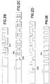
- FIGS. 2A-2Eare enlarged elevational views of exemplary rigid catheters having channels to provide a flexible distal tip in accordance with an embodiment of the present invention
- FIG. 3is an enlarged elevational view of an exemplary rigid catheter having channels to provide a flexible distal tip in accordance with another embodiment of the present invention
- FIG. 4is an enlarged elevational view of an exemplary rigid catheter having channels to provide a flexible distal tip in accordance with yet another embodiment of the present invention
- FIG. 5Ais an enlarged perspective view of an exemplary catheter having channels to provide a flexible catheter in accordance with another embodiment of the present invention
- FIG. 5Bis an enlarged cross-sectional view of the exemplary catheter of FIG. 5A ;
- FIG. 5Cis an enlarged cross-sectional view of an exemplary catheter constructed of rigid plastic and having channels to provide flexibility in accordance with another embodiment of the present invention
- FIG. 5Dis an enlarged cross-sectional view of an exemplary catheter constructed of rigid plastic and having channels to provide flexibility in accordance with another embodiment of the present invention
- FIGS. 6A-6Care enlarged perspective views of an exemplary catheter having a coiled construction to provide a flexible catheter in accordance with another embodiment of the present invention.
- FIG. 7is an enlarged cross-sectional view of an exemplary catheter and hub flexible union engagement comprising a ball-and-socket joint to provide a flexible connection in accordance with yet another embodiment of the present invention
- FIG. 8is an enlarged cross-sectional view of an exemplary catheter and hub flexible union engagement comprising a sliding plate junction to provide a flexible connection in accordance with yet another embodiment of the present invention
- FIG. 9is an enlarged cross-sectional view of an exemplary catheter and hub flexible union engagement comprising a bushing junction to provide a flexible connection in accordance with yet another embodiment of the present invention.
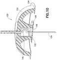
- FIG. 10is an enlarged cross-sectional view of an exemplary two-part hub with a flexible catheter in accordance with another embodiment of the present invention.
- FIG. 11is an enlarged cross-sectional view of an exemplary two-part hub with a flexible catheter in accordance with yet another embodiment of the present invention.
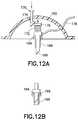
- FIGS. 12A and 12Bare an enlarged cross-sectional views of an exemplary hub with a retractable insertion catheter that is either flexible or rigid in nature, in accordance with another embodiment of the present invention.
- FIGS. 13A and 13Bare enlarged cross-sectional views of an exemplary hub with a retractable insertion catheter that is either flexible or rigid in nature, in accordance with yet another embodiment of the present invention
- FIG. 14illustrates the slight retraction of the insertion catheter that is either flexible or rigid in nature, within a sleeve to protect a sharpened end;
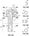
- FIG. 15Ais an enlarged cross-sectional view of an exemplary infusion catheter with formed rigid internal lumens and external polymer sleeve in accordance with yet another embodiment of the present invention.
- FIGS. 15B-15Eare sectional views of the infusion catheter taken along the lines A-A, B-B, C-C, and D-D of FIG. 15A , respectively;
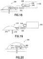
- FIG. 16illustrates an exemplary infusion pump with dual reservoirs and a dual lumen infusion set in accordance with an embodiment of the present invention
- FIG. 17Ais an enlarged cross-sectional view of an exemplary infusion catheter cast, molded or machined from a solid rod in accordance with an embodiment of the present invention
- FIG. 17Bis a perspective view of the infusion catheter of FIG. 17A ;
- FIGS. 18A-18Eillustrate an exemplary infusion catheter and forming sequence to produce such a multi-lumen cannula from a flat sheet in accordance with an embodiment of the present invention
- FIG. 19illustrates an exemplary infusion pump with two catheters, one for infusion into intradermal (ID) tissue and one for infusion into subcutaneous (SC) tissue in accordance with an embodiment of the present invention
- FIG. 20illustrates an exemplary infusion pump and set with an electronically controlled valve to selectively direct infusion to either the intradermal (ID) tissue, the subcutaneous (SC) tissue, or both the intradermal (ID) tissue and subcutaneous (SC) tissue in accordance with an embodiment of the present invention
- FIG. 21Aillustrates an exemplary fluidic valve configuration that selectively directs low-pressure flow to subcutaneous (SC) tissue and high-pressure flow to intradermal (ID) tissue in accordance with an embodiment of the present invention, wherein the valve configuration is shown in the high-pressure state; and
- FIG. 21Billustrates the fluidic valve configuration of FIG. 21A with the valve configuration shown in the low pressure state.
- the exemplary embodiments described belowaddress such unmet needs and illustrate a number of advanced, improved, and novel components and elements of current and future infusion sets and/or patch pumps, that further provide simplicity in manufacture and improvements in use for both insulin and non-insulin applications. For example, reducing or eliminating catheter kinking, occlusion and other undesired issues such as tissue inflammation and foreign body response, throughout the use cycle is an unmet need.
- the exemplary embodiments described in greater detail beloware hybrids, and incorporate multiple materials, components, features, and motions in combination, to substantially reduce and eliminate the conditions that result in catheter kinking, occlusion and other undesired issues such as tissue inflammation and foreign body response.
- Such exemplary embodimentsare presented in separate descriptions, although the individual features of these embodiments can be combined in any number of ways to meet the needs of the user.
- the exemplary embodiments of the present device described belowillustrate a number of features and elements in the areas of catheter design, construction and implementation to, for example, minimize the risk of occlusion, kinking, and other undesired issues such as tissue inflammation and foreign body response, while maintaining a degree of comfort to the user.
- a collection of exemplary elementsis shown by way of the example in FIG. 1 which serves to introduce the embodiments of the present invention described in greater detail below.
- FIG. 1illustrates an exemplary infusion set 10 including the following features.
- the exemplary infusion set 10can comprise a hub 12 , a catheter 14 , a fluid line tubeset 16 and a connector 18 . Additional infusion set elements and detail are omitted for clarity. Further, in an entirely self-contained patch device, the fluid line tubeset 16 and connector 18 are omitted.
- a number of exemplary embodiments of a catheter 14 and catheter-hub 14 / 12 connectionare described in greater detail, which can be provided for use with the exemplary infusion set 10 or any number of other similar devices.
- a cathetercan comprise a polymer tube that remains in-dwelling after an introducer needle is removed, for purposes of providing fluid communication from the infusion set to the infusion site.
- a cannulacan comprise a rigid tube, which can also remain in-dwelling.
- hybridsi.e. combinations of cannulae and cannulae features, and sleeves or catheters and catheter features, and function as in-dwelling, flexible cannulae.
- the hybrid, in-dwelling, flexible cannulaeare simply described as catheters.
- one or more lengths of the catheter wall of the catheter 14can be provided with one or more channels or grooves, and/or a coating such as a flexible sleeve or over-molded coating/sleeve, thereon, configured and arranged to provide a degree of flexibility.
- a number of benefits associated with the use of rigid materials in catheter constructioncan be provided while at the same time, benefits associated with the use of flexible materials in catheter construction can also be provided, and more specifically, can be provided at targeted areas. That is, for example, the grooves, channels, and/or coatings, can be configured to optimize strength to avoid occlusion, kinking, and other undesired issues such as tissue inflammation and foreign body response, and provide flexibility for user comfort.
- the catheteris not flexible, a greater degree of irritation and resulting inflammation can occur, causing a loss of patency or reduction in insulin uptake by the tissue at the infusion site, which will progressively degrade over time. Accordingly, the provision of a flexible catheter or catheter with a bio-interface facilitates the desired biological process in the tissue at the infusion site.
- Additional benefits of such channels or groovescan include but are not limited to, providing additional surface area for medication delivery in subcutaneous (SC) infusions, intradermal (ID) infusions, intramuscular (IM) infusions, and intravenous (IV) infusions, forming a cannula or needle with one or more of the features described above, to act as both an insertion cannula or needle, and an in-dwelling catheter, and forming a multi-lumen catheter to enable infusion to one or more tissue locations or types, either simultaneously or each intermittently, e.g. intradermal (ID) tissue and subcutaneous (SC) tissue.
- SCsubcutaneous
- IDintradermal
- IMintramuscular
- IVintravenous
- existing infusion set cathetersare manufactured of either rigid material, such as stainless steel, or soft materials, such as soft plastic, fluorinated polymers, and so forth.
- the soft plastic cathetersare prone to kink and/or occlude with normal wear, and the rigid catheters are often found to be uncomfortable and are not recommended for use beyond two days, as the rigidity of the catheter causes the user to feel movement within the tissue, and also causes flow cessation, due to movement in the tissue and the ensuing inflammatory response in the tissue.
- exemplary embodiments of the present inventioncomprise improved and novel elements of an infusion set for the delivery, or infusion, of insulin or other medications to a user via, for example, subcutaneous (SC) infusions, intradermal (ID) infusions, intramuscular (IM) infusions, and intravenous (IV) infusions.
- SCsubcutaneous
- IDintradermal
- IMintramuscular
- IVintravenous
- the infusion set 10typically comprises the hub 12 which includes the fixedly attached catheter 14 , and the tubeset 16 .
- the tubeset 16connects the hub 12 to an infusion pump or other insulin supply (not shown) via a connector 18 . In doing so, the tubeset 16 provides for fluid communication between the infusion pump reservoir and the hub 12 .
- the hub 12can be affixed to a patient's skin surface (not shown) using an adhesive (not shown) disposed on a lower surface of the hub.
- the catheter 14preferably protrudes from the lower surface of the hub 12 at a substantially perpendicular angle for at least a portion, although embodiments of the present invention are not limited thereto.
- the catheter 14 that extends from the lower surface of the hub 12can be comprised in part, or entirely of a rigid material such as stainless steel, nitinol, titanium, or a rigid plastic such as PEEK (Polyetheretherketone), polycarbonate, TOPASTM which is a COC, or similar materials.
- PEEKPolyetheretherketone
- TOPASTMwhich is a COC, or similar materials.
- a soft plastic catheteris prone to kink and/or occlude with normal wear, and a rigid catheter is often uncomfortable.
- a portion or length of the catheter 14 which is in contact with the tissue of the useris made flexible via a series or pattern of channels or grooves.
- the channels or groovesare designed to optimize column strength of the catheter 14 for improved catheter insertion, provide flexibility for user comfort, and further provide tensile strength for durability, insertion and removal.
- a portion of the overall catheter lengthcan extend inside the device and for purposes of the following descriptions, the catheter is recited as the portion extending from the hub, or alternately, the length of the catheter which extends from the hub.
- the cathetercan be provided with sufficient integrity and with a sharpened, self-piercing tip 30 , to allow the catheter to be implanted without the assistance of a rigid sleeve or guide, which is currently needed to pierce the tissue and resist damage to the catheter during deployment. Further, such exemplary embodiments of the present invention reduce the need for an intricate deployment mechanization, thereby reducing the overall size of the inserter and potentially allowing the inserter to become an integral part of the infusion pump.
- the catheter 14 a(not shown to size) is provided with a series or pattern of channels or grooves 24 .
- the catheter 14 a of FIG. 2Acomprises an outer diameter 20 , an inner diameter 22 , and one or more grooves 24 etched, cut, molded, or otherwise created (i.e., laser cut or chemically etched) in and/or through the catheter wall.
- the grooves 24 in the exemplary embodiment shownare provided at perpendicular angles to the inner/outer surfaces, and parallel to a bottom surface of the hub 12 .
- Each groove 24is spaced from adjacent grooves by uncut sections 26 , and spaced from adjacent parallel grooves by uncut sections 28 . Further, as shown in FIG. 2A , the uncut sections 26 are staggered such that at least one or more uncut sections 26 are not adjacent.
- the grooves 24can be any suitable size, but preferably between 0.05 mm to 0.5 mm wide and 0.5 mm to 1.0 mm long, the uncut sections 26 can be between 0.05 mm to 1.0 mm long and as wide as the grooves 24 , and the uncut sections 28 between grooves 24 can be between 0.05 mm to 1.0 mm.
- the channels or groovesare designed to provide flexibility in one, two, or more axis, and optimize column strength of the catheter for improved catheter insertion, hoop strength of the catheter to prevent collapse or kinking once implanted, provide flexibility for user comfort, and further provide tensile strength for durability, insertion and withdrawal.
- the series or pattern of channels 24are located near the end of the catheter 14 a . That is, the portion of the catheter 14 a closest to the hub 12 remains intact, and the series or pattern of channels 24 are provided near an opposite end of the catheter 14 a .
- the series or pattern of channels 24are ended at a point near a sharpened, self-piercing tip 30 , which can be beveled or sharpened to facilitate insertion through the patient's skin.
- An exemplary embodiment of such a sharpened, self-piercing tip 30is shown in greater detail in FIGS. 5A, 5B and 6 , described in greater detail below. As shown in greater detail in FIGS.
- the sharpened, self-piercing tip 30can comprise a radius cut to create a beveled tip.
- the cathetercan act also as the insertion needle, thereby further reducing the complexity of the insertion step.
- the series or pattern of channelsare positioned in a manner suitable to do so, such channels can also be used for targeted fluid communication.
- one or more of the channelscan be sealed with a biointerface sheath or coating such as a flexible sleeve or over-molded coating/sleeve, as described in greater detail below.
- the series or pattern of channelscan be provided near one or both opposite ends of the catheter, or at any portion therebetween, or any combination of each.
- the substantial entirety of the catheter bodycan be provided with such series or pattern of channels.
- the exemplary embodiments shownare for illustrative purposes only, and are not intended to limit the present invention to a specific distribution area of the series or pattern of channels.
- the catheter 14 acan be any suitable size, but preferably between 3.5 mm to 12 mm long, with an inner diameter 22 of between 0.20 mm to 0.78 mm and outer diameter 20 of between 0.25 mm to 0.8 mm.
- the first groove 24 at the distal end of the catheter 14 acan be provided between 0.5 mm and 2.0 mm from the distal end of the catheter, and the last groove can be provided between 2.5 mm to 3.0 mm from the base 12 . In doing so, a length of catheter 14 a between 1.5 mm and 9.0 mm long is provided with the channels 24 .
- the first groovemay interfere with the back angle of the sharp
- the first groovemay be provided at a greater distance from the distal end of the catheter.
- the channels or groovesare designed to provide flexibility in one, two, or more axis, and optimize column strength of the catheter for improved catheter insertion, strength of the catheter to prevent collapse or occlusion once implanted, provide flexibility for user comfort, and further provide tensile strength for durability.
- each of the channels 24are provided at perpendicular angles to the inner/outer surfaces, and parallel to a bottom surface of the hub 12 .
- the channelscan be provided at non-perpendicular angles.
- FIGS. 2B-2EA number of other exemplary embodiments of the present invention comprising channels provided at perpendicular angles to the inner/outer surfaces, and parallel to a bottom surface of the hub are shown in FIGS. 2B-2E .
- the cathetercan have alternating “upper” and “lower” channels 24 a.
- the catheteris shown having opposite “upper” and “lower” channels 24 b , and opposite “front” and “rear” channels 24 c (i.e., rotated 90 degrees from the upper and lower channels).
- the dimensions of the channels 24 b and 24 care similar to those of FIG. 2B .
- the catheteris shown having opposite “upper” and “lower” channels 24 d , but of lesser depth than those of FIG. 2B (i.e, the channels cross the center-line in the embodiment of FIG. 2B to allow flexibility in all directions, wherein the channels stop short or at the center-line in the embodiment of FIG. 2D ).
- FIG. 2Cthe catheter is shown having opposite “upper” and “lower” channels 24 b , and opposite “front” and “rear” channels 24 c (i.e., rotated 90 degrees from the upper and lower channels).
- the dimensions of the channels 24 b and 24 care similar to those of FIG. 2B .
- the catheteris shown having opposite “upper” and “low
- the catheteris shown having only “upper” channels 24 e , and of greater depth than those of FIGS. 2B, 2C and 2D .
- the width, depth, and other placement features of the channelscan be used as a factor to permit degrees and direction of flexibility.
- the catheter 14 b(not shown to size) can also be provided with a series or pattern of channel or grooves 34 which are configured in a saw-tooth pattern.
- the catheter 14 b of FIG. 3comprises the outer diameter 20 , the inner diameter 22 , and one or more grooves 34 etched, cut, molded, or otherwise created in and/or through the catheter wall.
- the grooves 34 in the exemplary embodiment shownare provided in a saw-tooth pattern relative to the inner/outer surfaces, and to a bottom surface of the hub 12 .
- Each groove 34is spaced from adjacent grooves by uncut sections 36 , and spaced from adjacent grooves by uncut sections 38 .
- an angle 40 of between 10 degrees and 45 degreescan be used, but the invention is not limited thereto.
- the grooves 34can be provided in a substantially sinusoidal pattern.
- the uncut sections 36can be staggered such that at least one or more uncut sections 36 are not adjacent.
- the grooves 34can be any suitable size, but preferably between 0.05 mm and 0.5 mm wide and 0.5 mm to 1.0 mm long, the uncut sections 36 can be between 0.05 mm to 1.0 mm long and as wide as the grooves 34 , and the uncut sections 38 between grooves 34 can be between 0.05 mm to 1.0 mm.
- the series or pattern of channels 34are also located near the end of the catheter 14 b . That is, the portion of the catheter 14 b closest to the hub 12 remains intact, and the series or pattern of channels 34 are provided near an opposite end of the catheter 14 b .
- the series or pattern of channels 34are ended at a point near a sharpened, self-piercing tip 30 , which can be beveled or sharpened to facilitate insertion through the patient's skin.
- the catheter 14 bcan be any suitable size, but preferably between 3.5 mm to 12 mm long, with an inner diameter 22 of between 0.20 mm to 0.78 mm and outer diameter 20 of between 0.25 mm to 0.8 mm.
- the first groove 34 at the distal end of the catheter 14 bcan be provided between 0.5 mm and 2.0 mm from the distal end of the catheter, and the last groove can be provided between 2.5 mm to 3.0 mm from the base 12 . In doing so, a length of catheter 14 b between 1.5 mm and 9.0 mm long is provided with the channels 34 .
- the first groovemay interfere with the back angle of the sharp, the first groove may be provided at a greater distance from the distal end of the catheter.
- the catheterprovides a means (i.e., cross-porting) for transferring drug to the infusion site tissue, and therefore the slots do not extend all the way back to the proximal end of the catheter. This distance, approximately 3 mm, is intended to position the cross-ports into the SC tissue, and inhibit drug flow to the intra-dermal (ID) tissue.
- a meansi.e., cross-porting
- the catheterhas been rendered flexible from a distance starting just behind the bevel of the tip and extending into the infusion set hub to allow the flexible catheter to “snake” from the flat plane or axis of the hub to enter and extend into the tissue perpendicular to that axis.
- the catheter 14 ccan also be provided with a series or pattern of channels or grooves 44 which are configured in a helix pattern oriented about a center axis of the catheter.
- a helixis a three-dimensional coil that runs along the surface of a cylinder, in this case, the body of the catheter.
- the catheter 14 c of FIG. 4comprises the outer diameter 20 , the inner diameter 22 , and one or more grooves 44 etched, cut, molded, or otherwise created in and/or through the catheter wall.
- the grooves 44 in the exemplary embodiment shownare provided in a helix pattern relative to the inner/outer surfaces, and to a bottom surface of the hub 12 , and oriented about a center axis of the catheter.
- Each groove 44is spaced from adjacent grooves by uncut sections 46 , and spaced from adjacent grooves by uncut sections 48 . Further, as shown in FIG. 4 , the uncut sections 46 are staggered such that at least one or more uncut sections 46 are not adjacent.
- the grooves 44can be any suitable size, but preferably between 0.05 mm and 0.5 mm wide and 0.5 mm to 1.0 mm long, the uncut sections 46 can be between 0.05 mm to 1.0 mm long and as wide as the grooves 44 , and the uncut sections 48 between grooves 44 can be between 0.05 mm to 1.0 mm.
- the series or pattern of channels 44are also located near the end of the catheter 14 c . That is, the portion of the catheter 14 c closest to the hub 12 remains intact, and the series or pattern of channels 44 are provided near an opposite end of the catheter 14 c .
- the series or pattern of channels 44are ended at a point near a sharpened, self-piercing tip 30 , which can be beveled or sharpened to facilitate insertion through the patient's skin.
- the catheter 14 ccan be any suitable size, but preferably between 3.5 mm to 12 mm long, with an inner diameter 22 of between 0.20 mm to 0.78 mm and outer diameter 20 of between 0.25 mm to 0.8 mm.
- the first groove 44 at the distal end of the catheter 14 ccan be provided between 0.5 mm and 2.0 mm from the distal end of the catheter, and the last groove can be provided between 2.5 mm to 3.0 mm from the base 12 . In doing so, a length of catheter 14 c between 1.5 mm and 9.0 mm long is provided with the channels 44 .
- the first groovemay interfere with the back angle of the sharp, the first groove may be provided at a greater distance from the distal end of the catheter.
- the substantial entirety of the catheter body between distal and proximal endscan be provided with such series or pattern of channels.
- the series or pattern of channelsmay not be positioned for fluid communication and therefore, one or more of the channels can be sealed with a biointerface sheath or coating such as a flexible sleeve or over-molded coating/sleeve, as described in greater detail below.
- a devicecan be configured to provide a cannula or needle with one or more of the features described above, to act as both an insertion cannula or needle, and an in-dwelling catheter.
- a rigid catheter 14 dfor example, stainless steel
- a sharpened, self-piercing tip 30and alternating, parallel slots 52 , etched, cut, molded, or otherwise created (i.e., laser cut or chemically etched) in and/or through the catheter wall, along the substantially entire shaft of the catheter.
- the slots 52can be provided substantially as described above in regard to the exemplary embodiment of FIGS.
- spacing between slots 52can be configured to provide the slight overlap of the slot ends as shown, or as described above in regard to the exemplary embodiment of FIGS. 3 and 4 .
- the above numerical dimensionscan result in a slot/spacing relationship that can change.
- the shortest length sloti.e., 0.5 mm long, would only allow one attachment point around the diameter, which could limit design alternatives and device performance.
- the catheter of extreme values, or any value therebetweencan be designed to have a wall thickness of T (i.e., with an outside diameter of approximately 3 T, and an inside diameter of approximately T).
- each of channels 52can be between 1 T to 6 T wide, and preferably between 2 T and 3 T.
- the uncut spaces between channelscan be between 1 T and 6 T, and preferably between 2 T and 3 T.
- the alternating slots 52enable the catheter 14 d to flex, yet provide a rigidity or column strength necessary for insertion into the user's skin, but flex to provide a comfortable in-dwelling catheter.
- the exemplary stainless steel catheter 14 dis preferably a unitary body having a sharpened, self-piercing tip 30 at the distal end. As shown in FIG. 5A , the sharpened, self-piercing tip 30 can comprise a radius cut to create a beveled tip. Where the catheter is provided with such a sharpened, self-piercing tip to allow the insertion, the catheter can act as the insertion needle, thereby further reducing the complexity of the insertion step.
- the catheter 14 dcan be sheathed or coated over some desired portion by a coating, such as Vialon® or Teflon®, to create a sleeve 54 a that provides a biocompatible outer fluid seal for enabling a drug fluid to enter to the user through the tip of the catheter, provide a seal so that leakage does not occur through the slots 52 , and/or provide a cover into which the insertion cannula or in-dwelling catheter can be slightly retracted to cover the sharpened end thereof.
- a coatingsuch as Vialon® or Teflon®
- the outer sheath or sleeve 54 acan be processed to the appropriate inner diameter and pulled over the catheter 14 d for attachment. Depending on the specific sheath or sleeve material, the attachment may be facilitated by a dip coating process, heat shrinking, bonding, or any other suitable process.
- the outer sheath or sleeve 54 acan comprise a polymer sleeve, such as Teflon® or Vialon®, which can be used to cover the stainless steel in-dwelling catheter and provide a bio-interface between the tissue and the needle and/or to also seal the slots in the flexible in-dwelling cannula. Additional disclosure of the exemplary Vialon® material can be found in commonly assigned U.S. Pat. Nos.
- any suitable fluid tight materialcould be used to form the sheath or coating such as the flexible sleeve or over-molded coating/sleeve.
- a material which can become softer and/or more flexible once insertedcan also be used.
- FIGS. 5C and 5Dare enlarged cross-sectional views of a portion of exemplary catheters constructed of rigid plastic and having channels to provide flexibility in accordance with embodiments of the present invention.
- an exemplary catheter 14 eis shown constructed of injection molded rigid plastic, wherein the slots 24 f provide flexibility. As the catheter 14 e is injection molded, the slots 24 f , needle point, and all other finished features can be molded in any configuration desired such that no secondary operations would be required. Further, as with the embodiment shown in FIG. 5A , an over-molded outer sheath or sleeve 54 b can comprise a polymer, such as Teflon® or Vialon®, and be used to cover the catheter, provide a bio-interface between the tissue and the catheter, and/or seal the slots in the catheter.
- a polymersuch as Teflon® or Vialon®
- FIG. 5DA similar exemplary embodiment is shown in FIG. 5D in which an exemplary catheter 14 f is shown constructed of injection molded rigid plastic, wherein the slots 24 g provide flexibility. As the catheter 14 f is again injection molded, the slots 24 g , needle point, and all other finished features can be molded in any configuration desired such that no secondary operations would be required.
- an extruded outer sheath or sleeve 54 ccan comprise a polymer sleeve, such as Teflon® or Vialon®, and be used to cover the catheter, provide a bio-interface between the tissue and the catheter, and/or seal the slots in the catheter.
- the outer sleevecan be over-molded as part of a 2-shot molding process, or can be extruded separately and assembled to the insertion cannula or in-dwelling catheter.
- FIG. 6AStill another exemplary embodiment wherein the substantially entire catheter body can be provided with such series or pattern of channels is shown in FIG. 6A , and preferably comprises a catheter 14 g with a sharpened rigid, such as stainless steel, needle tip 32 , attached to a torsion spring 56 .
- the needle tip 32 and sharpened, self-piercing tip 30 thereofenables penetration into the user's skin and is preferably welded to the torsion spring 56 , but may be attached using any suitable method.
- the torsion spring 56provides similar benefits as the embodiments described above in that it provides column strength for insertion, flexibility for user comfort, and tensile strength for durability.
- Such a torsion spring 56can be sheathed or coated over some desired portion by a coating such as a flexible sleeve or over-molded coating/sleeve material, such as a Vialon® or Teflon® sleeve 58 for sealing the communicated fluid within the inner cavity of the torsion spring.
- the torsion spring 57can also be laser cut or chemically etched from the proximal portion of the solid steel cannula, i.e. behind the sharp tip 30 , by lasing a continuous spiral or helix.
- the proximal endcould either be opened or closed (i.e., open to deliver contents, or closed to urge content delivery through other openings).
- the one-piece spiral or helix cut structureenables the shaft to be flexible, the column strength to be maintained which enables insertion, and allows hoop strength to be maintained which prevents collapse of the inner lumen.
- the torsion spring 57can be sheathed or coated over some desired portion by a coating such as a flexible sleeve or over-molded coating/sleeve material, such as a Vialon® or Teflon® sleeve 58 for sealing the communicated fluid within the inner cavity of the torsion spring.
- a coatingsuch as a flexible sleeve or over-molded coating/sleeve material, such as a Vialon® or Teflon® sleeve 58 for sealing the communicated fluid within the inner cavity of the torsion spring.
- the torsion spring 56can be manufactured from a continuous length of torsion spring, and then lasing a continuous weld to connect a number of coils at the end of the spring, and then grinding the welded end to create the bevel end 31 .
- the torsion spring 57can be sheathed or coated over some desired portion by a coating such as a flexible sleeve or over-molded coating/sleeve material, such as a Vialon® or Teflon® sleeve 58 for sealing the communicated fluid within the inner cavity of the torsion spring.
- the exemplary catheters described abovecan be provided with any suitable wire or spring cross section, inner diameter, and outer diameter, and may alternatively comprise a rectangular cross-section to maximize the internal diameter, as would be appreciated by one of ordinary skill in the art. Additionally, the ends of each do not need to comprise an opening for the flow of drug to the user. It may desirable to implement an embodiment with a closed end, and having side ports located near the tip or elsewhere for enabling the flow of drug to the user.
- An exemplary catheter having a plurality of holes at or near a tapered tip, and a method of constructing and using such a catheteris described in U.S.
- a flexible cathetercan be coupled with a sharpened tip optionally hardened relative to the catheter for entering the user's skin.
- An additional feature to be used in any of the above embodimentsprovides a means for heparinizing the catheter. Heparinization of the catheter may be performed prior to initial insertion into the user's skin or during the variable insertion and retraction motions. Heparinization may be performed by coating the catheter with heparin by any method available to one of ordinary skill in the art. A heparinized catheter may facilitate preservation of the infusion site by preventing blood coagulation at the infusion site which may block or otherwise complicate the infusion site.
- the drug Heparinis one in a family of anti-coagulants and one of ordinary skill in the art would appreciate that similar drugs can be substituted to achieve the same benefits without departing from the scope and spirit of embodiments of the present invention.
- a portion or length of the catheteris made flexible, while maintaining a rigid portion or length of the catheter.
- the channels or groovesare designed to optimize column strength of the catheter for improved catheter insertion, provide flexibility for user comfort, and further provide tensile strength for durability.
- the width of each channel, the length of each channel, width of each bridge or uncut sections between channels, width of uncut sections between parallel channels, angle or pitch of channels relative to the axis of the catheter, and the number of coursescan be determined to provide a desired minimum bend radius of the distal section of the catheter axis, and the maximum arc of displacement.
- the channels or groovescan be configured to pass entirely through the thickness of the catheter, or can be configured to pass through one wall of the catheter, that is, entirely between the outer and inner surfaces or some portion thereof.
- a combination of any of the above configured grooves or channelscan be provided as desired. That is, one or more of the grooves or channels illustrated in FIGS. 2-6 , including the coatings or sheaths, can be provided in a single catheter.
- the presence of the channels or grooves at the distal section of the catheteralso allows additional surface area for medication delivery to the tissue of the user. That is, when a substance is delivered to a targeted area via the catheter, some delivery occurs via the provided grooves or channels when desirable to do so.
- the cathetercan be sheathed or coated over some desired portion by a coating, such as Vialon® or Teflon®, to create a sleeve that provides a biocompatible outer fluid seal for enabling a drug fluid to enter to the user through the tip of the catheter, and provide a seal so that leakage doesn't occur through the slots.
- the channels or groovescan be constructed using laser machining, electrical discharge machining (EDM), metal injection molding (MIM), plastic injection molding, chemical etching, or similar techniques, such that the channels or grooves are cleanly cut through the wall of the catheter without creating obstacles, undesired edges, or dead spaces.
- the cathetercan be reworked (i.e. a secondary operation) after the process used to induce flexibility, e.g. laser cutting, EDM, chemical etch, etc.
- electropolishingcan be used to remove surface imperfections, and create an oxide layer for improved biocompatibility and corrosion resistance.
- Passivationcan be used with stainless steel and catheters produced from other metals with some amount of ferrous composition, e.g. nitinol, to remove iron contamination from the surface.
- Microblastingcan also be used to establish a clean, textured surface for over-molding.
- the cathetercan act as the insertion needle and can remain in-dwelling, thereby further reducing the complexity of the insertion step.
- a cathetercan be sheathed or coated over some desired portion by a coating such as a flexible sleeve or over-molded coating/sleeve material, such as a Vialon® or Teflon® sleeve.
- exemplary embodiments of the present inventionare further provided to enable the hub to move with the skin while minimizing any effect of such movement on the catheter and the insertion site.
- a flexible unioncan be provided by, but are not limited to, a ball-and-socket joint, a sliding plate junction, a separate inner hub with a separate adhesive attachment a flexible tubing connection, and a flexible bushing junction (including a bellows connection or bellows joint), provided between the catheter and the hub or patch pump.
- Still further embodiments of the present inventioncan comprise two or more separate hubs as part of one infusion device, such as the outer hub and the catheter hub, each attached to the surface of the skin with a separate adhesive and wherein the flow between the two is preferably accomplished through a flexible fluid line or other similar connections means to isolate shock or applied forces from the surface of the outer hub to the catheter.
- the two hubswhich can be attached to the surface of the skin as a single device, can be further configured such that the inner hub maintains the catheter position relative to the tissue in which the catheter has been inserted, and thereby reduce and eliminate irritation of the tissue and the cascade of events resulting from a foreign body response.
- FIG. 7is an enlarged cross-sectional view of a hub, such as provided with a patch pump, incorporating one such exemplary catheter and hub engagement comprising a ball-and-socket joint in accordance with an embodiment of the present invention.
- a hub 60is shown having a fluid, medication or other content storing reservoir 62 positioned above or in fluid communication with a catheter 64 .
- a ball joint 66can be secured or otherwise formed at one end of the catheter 64 , and is provided to rotatably secure the catheter 64 with the lower surface of the hub 60 .
- a lower portion of the hub 60 bodycan comprise a circular detent opening 68 or other similar opening into which the ball joint 66 of the catheter 64 can be captured.
- the circular detent opening 68can be sized to allow the ball joint 66 to be press-fit into and thereafter captured by the circular detent opening 68 .
- the ball joint 66may also be captured within the circular detent opening 68 by manipulating one or more elements of the hub 60 to allow expansion and contraction of the detent opening 68 to facilitate installation and thereafter capture of the ball joint 66 within the detent opening 68 , or the ball joint 66 may be captured within the detent opening 68 during the assembly of the body of the hub 60 .
- the catheter 64is free to rotatably move relative to the hub 60 in a number of directions, such as those illustrated by the directions of arrows A and B. That is, the catheter 64 of FIG. 7 is free to rotate to the extent permitted by a bottom opening 70 of the detent opening 68 in the lower surface of the body of the hub 60 .
- the catheter 64can comprise any suitable catheter, such as those described above, and the ball joint 66 can be formed of a material identical or similar to that of the catheter 64 , and can comprise an opening therethrough to allow uninterrupted fluid communication during rotation and at each rotated position of the catheter 64 and ball joint 66 .
- the junction between the catheter 64 and the hub 60can be sealed to prevent leakage either from the chamber 62 or into the chamber 62 , by one or more sealing elements 72 .
- the sealing element 72can comprise any number of suitable elements, such as one or more O-rings, bushings, washers, molded elements or similar sealing elements.
- the sealing element 72can be further configured to control the rotatable movement of the catheter 64 by providing a degree of friction between the ball joint 66 of the catheter 64 and the hub 60 .
- the hub 60can further comprise additional elements, such as the adhesive layer 74 to secure the hub 60 to a skin surface for use, and still other elements which are omitted from the illustration of FIG. 7 for clarity.
- the ball joint 66can comprise a substantially circular element having a diameter of any suitable size, but preferably between 0.5 mm to 4.0 mm. Accordingly, the detent opening 68 can have a diameter between 0.5 mm to 5.0 mm, and the bottom opening 70 of the detent opening can have a diameter between 0.4 mm to 3.8 mm wide. In embodiments of the present invention, the bottom opening 70 can be circular, oval, or any shape desired to provide the needed degrees of movement.
- a sliding platecan be provided to allow movement between the catheter and hub, and/or a flexible bushing can be provided to allow movement between the catheter and hub.
- degrees of movementare provided by each of the ball-and-socket, sliding plate, and flexible bushing, subtle differences in the movement provided by each (i.e., rotational, slidable, or combinations thereof) can result in a preference for one exemplary embodiment in a specific application.
- FIG. 8is an enlarged cross-sectional view of a hub, such as provided with a patch pump, incorporating an exemplary catheter and hub engagement comprising such a sliding plate junction in accordance with another embodiment of the present invention.
- a hub 80is shown having a fluid, medication or other content storing reservoir 82 positioned above or in fluid communication with a catheter 84 .
- the catheter 84comprises an element at one end, such as the planar element 86 , which is slidably captured in an opening 88 to slidably secure the catheter 84 with the lower surface of the hub 80 .
- a lower portion of the hub bodycan comprise the opening 88 , formed between a lower surface of the chamber 82 and one or more elements 90 captured in one or more notches 92 , into which the planar element 86 can be captured.
- the notch 92is formed in an inner wall of the reservoir 82 and encircles the entire circumference of the reservoir.
- the element 90can comprise a substantially circular washer-shaped member which can be assembled into the notch 92 .
- a thickened portion of the element 90can be provided to secure the element 90 into the notch 92 .
- a narrower portion of the element 90can be provided near a central opening 94 to allow a degree of deflection to assist in holding the planar member 86 and sealing elements 96 described in greater detail below.
- the planar element 86can be captured within the opening 88 through the assembly of the hub body or in a similar manner. In doing so, the catheter 84 is free to move relative to the hub 80 in a number of directions, such as those illustrated by the directions of arrows A′ and B′. That is, the catheter 84 of FIG. 8 is free to slide to the extent permitted by the bottom opening 98 in the lower surface of the hub 80 , and/or as permitted by the travel of the planar member 86 within the opening 88 . Some rotational movement of the catheter 84 relative to the hub 80 can also be provided as permitted by the deflection of the element 90 by the planar member 86 (see for example, the arrows A and B of FIG. 7 ).
- the catheter 84can comprise any suitable catheter, such as those described above.
- the planar member 86can be formed of a material identical or similar to that of the catheter 84 , and can comprise an opening therethrough to allow uninterrupted fluid communication during sliding and at each position.
- the securing element 90can also be formed of a material identical or similar to that of the planar member 86 , the hub 80 , or any other suitable material.
- the junction between the catheter 84 and the hub 80can be sealed to prevent leakage either from the chamber 82 or into the chamber 82 by one or more sealing elements 96 .
- the sealing elements 96can comprise any number of suitable elements, such as O-rings, bushings, washers, molded elements or similar sealing elements. In yet other exemplary embodiments of the present invention, a U or cup shaped, X shaped or other type of wipe seal can be used, and provide additional benefits in that the sealing forces are reduced.
- the sealing elements 96can be further configured to control the slidable movement of the catheter 84 by providing a degree of friction between the planar member 86 of the catheter 84 and the walls of the opening 88 of the hub 80 .
- the hub 80can further comprise elements such as the adhesive layer 74 to secure the hub to a skin surface for use.
- the planar member 86can be circular, oval, or any shape desired to provide the needed degrees of movement.
- the planar member 86can comprise a substantially circular element having a diameter of any suitable size, but preferably between 1.0 mm to 10.0 mm and a thickness of between 0.5 mm to 1.0 mm.
- the bottom opening 98can have a diameter between 1.0 mm to 5.0 mm.
- the bottom opening 98can be circular, oval, or any shape desired to provide the needed degrees of movement.
- FIG. 9shows an enlarged cross-sectional view of a hub, such as provided with a patch pump, incorporating an exemplary catheter and hub engagement comprising a flexible bushing junction in accordance with yet another embodiment of the present invention.
- a hub 100is shown having a fluid, medication or other content storing reservoir 102 positioned above or in fluid communication with a catheter 104 .
- a flexible bushing 106can be secured or otherwise formed at one end of the catheter 104 , and is provided to rotatably and/or slidably secure the catheter 104 with the lower surface of the hub 100 .
- a lower portion of the hub body or reservoir 102can comprise an opening into which the flexible bushing 106 can be captured.
- the openingcan be sized to allow the flexible bushing 106 to be press fit into and thereafter captured by the lower portion of the reservoir 102 .
- the flexible bushing 106may also be captured within the hub 100 through the assembly of the hub body or in a similar manner. In doing so, the catheter 104 is free to move in a number of directions, such as those illustrated by the directions of arrows A′′ and B′′. That is, the catheter 104 of FIG. 9 is free to rotate to the extent permitted by the flexibility of the flexible bushing 106 and a bottom opening 110 in the lower surface of the body of the hub 100 .
- the flexible bushing 106can comprise an outer diameter sufficient to be captured at a lower portion of the reservoir 102 .
- the bushing 106can further comprise a reduced portion 108 having an outer diameter sufficient to be captured within and seal the opening 110 .
- exemplary embodiments of the bushing 106can be comprised of a soft, low durometer, flexible material, which can also be configured to create the fluid seal, and which creates a flexible joint between the catheter 104 and the pump body or hub 100 .
- the catheter 104can comprise any suitable catheter, such as those described above.
- the flexible bushing 106can further comprise an opening therethrough to allow uninterrupted fluid communication during rotation and/or sliding, and at each rotated or slid position. Further, the junction between the catheter 104 and the flexible bushing 106 , and between the flexible bushing 106 and the hub 100 can be sealed to prevent leakage either from the chamber 102 or into the chamber 102 by selection of the materials of the flexible bushing 106 and/or by the selection of materials securing the flexible bushing 106 within the hub 100 .
- the hub 100can further comprise elements such as the adhesive layer 74 to secure the hub to a skin surface for use.
- the flexible bushing 106can be circular, oval, or any shape desired to provide the needed degrees of movement.
- the flexible bushing 106can comprise a substantially circular element having diameter of any suitable size, but preferably between 2.0 mm to 10.0 mm, and a diameter at the reduced portion 108 between 1.0 mm to 9.0 mm.
- the bottom opening 110can have a diameter between 1.0 mm to 9.0 mm.
- the bottom opening 110can be circular, oval, or any shape desired to provide the needed degrees of movement.
- the exemplary embodiments of the present inventioncan provide a flexible union between the catheter and the hub.
- infusion sets and patch pumpsare typically applied to a user's skin and have catheters that extend through the user's skin and into the subcutaneous tissue or other tissue, depending upon the specific use in either subcutaneous (SC) infusions, intradermal (ID) infusions, intramuscular (IM) infusions, and intravenous (IV) infusions.
- the cathetersprovide a fluid pathway for delivery of medication, such as insulin, into the tissue.
- medicationsuch as insulin
- the cathetercan be provided with channels, grooves and coatings such as a flexible sleeve or over-molded coating/sleeve, and the junction of the catheter to the hub can be comprised of a ball-and-socket joint, a sliding plate, a flexible bushing, or similar design, to enable the catheter to move and move relative to the hub.
- the junctioncan be further configured to be sealed to prevent leakage of contents through the junction.
- the cathetercan act as the insertion needle and can remain in-dwelling, thereby further reducing the complexity of the insertion step.
- Still further embodiments of the present inventioncan comprise an exemplary two-part hub with a flexible catheter as part of one infusion device.
- a device having two separate hubs as part of one infusion device, such as the outer hub and the catheter hubcan each be attached to the surface of the skin with a separate adhesive and the insulin flow between the two is preferably accomplished through a flexible fluid line or other similar connections means to isolate shock or applied forces from the external surface of the outer hub to the catheter.
- the two hubswhich can be attached to the surface of the skin as a single device, can be further configured such that the inner hub maintains the catheter position relative to the tissue in which the catheter has been inserted, and thereby reduce and eliminate irritation of the tissue and the cascade of events resulting from a foreign body response.
- such a device 120is shown in FIG. 10 and comprises a housing 122 and housing adhesive 124 , and a needle hub 126 and needle hub adhesive 128 .
- a flexible connection 130is provided between the outer housing 122 and the needle hub 126 .
- a minimal gap 132is provided between the outer housing 122 and the needle hub 126 , such that the outer housing 122 can provide an envelope for the attachment and location of the needle hub 126 therein, but any force or movement conveyed to the outer housing 122 is not transferred to the needle hub 126 .
- the embodimentcomprises a single device having two separate hubs 122 and 126 as part of one infusion device 120 , wherein each can be attached to the surface of the skin with separate adhesive layers 124 and 128 and the insulin flow between the two is accomplished through the flexible fluid line or other similar connections means 130 to isolate shock or applied forces from the external surface of the outer hub 122 to the catheter 134 .
- the two hubs 122 and 126can be attached to the surface of the skin as a single device, and can be configured such that the inner hub 126 maintains the catheter 134 position relative to the tissue in which the catheter 134 has been inserted, and thereby reduce and eliminate irritation of the tissue and the cascade of events resulting from a foreign body response.
- FIG. 11Another exemplary embodiment of the present invention providing such a two-part hub with a flexible catheter is illustrated in FIG. 11 .
- the device 140 of FIG. 11comprises a housing 142 and housing adhesive 144 , and a needle hub 146 and needle hub adhesive 148 .
- a flexible connection 150is provided between the outer housing 142 and the needle hub 146 , such that the outer housing 142 can provide an envelope for the attachment and location of the needle hub 146 therein, but any force or movement conveyed to the outer housing 142 is not transferred to the needle hub 146 and catheter 152 .
- FIGS. 12A and 12B , and FIGS. 13A and 13Bare enlarged cross-sectional views of exemplary hub devices with a retractable insertion cannula or in-dwelling catheter that is either flexible or rigid in nature, in accordance with another embodiment of the present invention.
- the device 160can comprise an outer hub 162 , inner hub 164 , retractable insertion cannula or in-dwelling catheter 166 , and a blunt cannula 168 .
- a retraction systemcomprising a push button or other lever 170 can be provided through the outer hub 162 to secure and then release the insertion cannula or in-dwelling catheter 166 as urged by a biasing element such a spring.
- the button 170can comprise a shoulder, detent or other similar element to hold a position of the insertion cannula or in-dwelling catheter 166 through contact, such as the contact between detent 174 and shoulder 176 of the insertion cannula or in-dwelling catheter 166 .
- the button 170When pressed, the button 170 releases the shoulder 176 and the insertion cannula or in-dwelling catheter is urged upward by the spring 172 for a short distance, thereby shielding the sharpened end of the insertion cannula or in-dwelling catheter within the blunt cannula 168 . Fluid communication to the insertion cannula or in-dwelling catheter is then achieved through the connection of tubing 178 .
- the insertion cannula or in-dwelling catheter 166is retracted upward within the blunt cannula 168 as shown in the retracted illustration of FIG. 12B .
- FIG. 13AA second exemplary embodiment is shown in FIG. 13A , wherein the device 180 can comprise an outer hub 182 and outer hub adhesive layer 184 , inner hub 186 and inner hub adhesive layer 188 , blunt cannula 190 , and a retractable insertion cannula or in-dwelling catheter 192 .
- a retraction systemis activated by simply pressing down on the outer hub 182 . As shown in FIG.
- the over-center hinges 194permit travel of the inner hub 186 which retracts the retractable insertion cannula or in-dwelling catheter 192 over the blunt cannula 190 such that the sharpened end of the insertion cannula or in-dwelling catheter is raised above the end of the blunt cannula 190 as shown in FIG. 13B . Fluid communication to the catheter is then achieved through the connection of tubing 196 .
- the inner hub 186can further comprise any number of suitable sealing elements between inner and outer needles using for example, a seal or lubricant.
- FIG. 14illustrates such a partially retracting needle concept wherein the insertion cannula or in-dwelling catheter that is either flexible or rigid in nature, is shown in a pre-use position with a sharpened end exposed, a post-use position where the insertion cannula or in-dwelling catheter and sleeve are shown in an SC tissue position, and in a retracted position wherein the insertion cannula or in-dwelling catheter is retracted within the outer sleeve a distance sufficient to cover the sharpened end of the insertion cannula or in-dwelling catheter.
- the sharpened end of the insertion cannula or in-dwelling catheteris no longer exposed and allowed to irritate the SC tissue. Further, kinking of the Teflon® or Vialon® insertion cannula or in-dwelling catheter can be reduced by leaving the insertion cannula or in-dwelling catheter in the outer sheath in the inserted position.
- FIG. 14is shown in use in a subcutaneous (SC) infusion, the embodiment can also be used in intradermal (ID) infusions, intramuscular (IM) infusions, and intravenous (IV) infusions. Further, the in-dwelling catheter shown in FIG. 14 can be either rigid/solid (i.e. without slots), or flexible (i.e. with slots).
- FIG. 15A further embodiment is shown in FIG. 15 wherein the catheter is configured to provide infusion to both intradermal (ID) tissue and subcutaneous (SC) tissue, either simultaneously or each intermittently as required to satisfy the drug delivery needs of the patient.
- IDintradermal
- SCsubcutaneous
- the insertion cannularetracts to protect the tissue from the sharp edges of the needle tip, after placing the catheter into the tissue.
- the insertion cannula or introducer needle in FIG. 15is shown in the retracted position, and the needle is formed in a manner to provide two distinct fluid paths in combination with the polymer outer sleeve.
- a device 200including a formed cannula such as the exemplary steel cannula 202 , over which a sleeve such as the polymer sleeve 204 is formed, and which are further aligned in a manner to provide fluid communication between each, via a cross-port 206 , 208 and 210 .
- the cross-port 206is provided to be in fluid communication with chamber 212
- the cross-port 208is provided to be in fluid communication with chamber 214 .
- the chamber 212is in fluid communication with a first reservoir providing for example, a fast-acting medicament
- the chamber 214is in fluid communication with a second reservoir providing for example, a slow-acting medicament (see for example, FIG. 16 ).
- Each elementcan be supported within or upon an infusion hub 216 .
- the device 200 of FIG. 15Acan be placed upon an insertion site to reach the ID tissue space 218 and an SC tissue space 220 .
- the cross-port 210is configured to access the ID tissue space 218
- an open proximal end of the steel cannula 202 and the polymer sleeve 204is configured to access the SC tissue space 220 .
- the steel cannula 202is crimped fully closed at a distal end 222 shown by view A-A of FIG. 15B , fully uncrimped at a point shown by view B-B of FIG. 15C , partially crimped at a point shown by view C-C of FIG.
- the single steel cannula 202 and polymer 204create first and second flow paths 226 and 228 , wherein flow path 226 is configured to provide communication between the cross-port 206 and the cross-port 210 , and the flow path 228 is configured to provided communication between the cross-port 208 and the open proximal end 224 via the opening 230 .
- the steel cannulacan be sharpened at this end as shown, or can be blunt.
- the first path 226 which provides fluid to the intradermal (ID) tissue 218is through the cross-port 206 in the cannula 202 which aligns with a similar opening in the polymer sleeve 204 , when the cannula 202 is in the retracted position.
- the fluid path 226continues through the internal lumen of the cannula 202 and exits through a similar cross-port 210 into the intradermal (ID) tissue 218 .
- the second fluid path 228is through the cross-port 208 in the external polymer sleeve 204 and continues in the lumen created between the inner surface of the polymer sleeve 204 and the outer surface of the cannula 202 , and exits out through the end 224 of the catheter into subcutaneous (SC) tissue 220 .
- SCsubcutaneous
- This alternative embodimentenables infusion into at least two sites, e.g. intradermal (ID) tissue and subcutaneous (SC) tissue, each tissue having distinctive behavior for insulin up-take as described in U.S. Patent Publication No. 2002/0095134, of Pettis et al., the entire disclosure of which being expressly incorporated herein by reference.
- basal insulin infusionis continuous throughout the day with subtle changes in the infusion rate to compensate for changes in activity and stress.
- basal requirementshave been satisfied by slow-acting insulin.
- Bolus insulin infusionis used to compensate for carbohydrate consumption at meals and also to correct for high blood glucose, i.e. hyperglycemia.
- Fast-acting insulinprovides the best therapy for bolus infusion.
- Insulin up-takeis much faster in intradermal (ID) tissue as compared to subcutaneous (SC) tissue. Therefore, the exemplary embodiment shown in FIG. 15A can be used to infuse fast-acting insulin into the intradermal (ID) tissue for bolus requirements and infuse slow-acting insulin into subcutaneous (SC) tissue for basal requirements.
- an exemplary infusion pump 232is shown that is configured to support the device 200 of FIG. 15A .
- the infusion pump 232can incorporate at least two reservoirs 234 and 236 , one for fast-acting insulin and a second for slow-acting insulin.
- the infusion setcan further provide two separate lumens 238 and 240 , which would connect to the separate chambers within the set hub.
- the two separate lumens 238 and 240can be incorporated into a single lumen with multiple channels (not shown).
- Yet another exemplary embodiment of the present inventioncan include a formed cannula as shown in FIG. 17A , wherein the cannula has been replaced with a solid rod into which two channels have been formed or machined.
- the cannula of the device 250has been replaced with a solid rod 252 into which two channels 256 and 258 have been formed or machined.
- the remaining featuresare substantially as described in regard to FIG. 15A .
- the cross-ports 206 and 208 in the external polymer sleeve 204 in combination with the channels 256 and 258provide two separate fluid pathways to deliver different or similar drugs to the intradermal (ID) tissue and subcutaneous (SC) tissue in a manner substantially similar to that of FIG. 15A .
- FIG. 17BA perspective view of the exemplary solid rod 252 into which two channels 256 and 258 have been formed or machined is shown in FIG. 17B .
- the rod 252can be sharpened at the end as shown, or can be blunt.
- a dual lumen catheter or cannula 260can be formed from a flat sheet of any suitable material as shown in FIG. 18B , rolled in the direction of arrows A and B as shown in FIG. 18C until substantially reaching a final desired shape as shown in FIG. 18D , and then either welded to close and seal the lumens as shown in FIG. 18E , or captured within an external polymer sleeve (not shown), such that two separate fluid pathways 262 and 264 are provided to deliver different or similar drugs to the intradermal (ID) tissue and subcutaneous (SC) tissue.
- IDintradermal
- SCsubcutaneous
- the dual lumen cannula 260can be extruded or injection molded into a form that is similar to those shown in FIGS. 17A-17B and 18A-18D .
- the extrusion processwould produce a continuous cross-section, similar to that shown in FIG. 18E .
- Injection moldingcould be utilized to produce the cannula shown in FIGS. 17A and 17B .
- two or more separate catheterscan be used to provide the desired two or more separate fluid pathways to deliver different or similar drugs to the intradermal (ID) tissue and subcutaneous (SC) tissue.
- the exemplary embodiment shown in FIG. 19includes the device 270 having the two separate catheters 272 and 274 , and is shown connected to the exemplary infusion pump 232 incorporating at least two reservoirs, one for fast-acting insulin and a second for slow-acting insulin.
- the catheter 272can be provided for targeting the ID tissue
- the catheter 274can be provided for targeting the SC tissue.
- a valve arrangementcan be provided, such as with the infusion hub, to redirect the high-pressure bolus dose to the intradermal (ID) tissue.
- the valve 20illustrates an exemplary hub 280 having such a valve 282 disposed within the hub and coupled between the first and second chambers 212 and 214 , and the infusion pump (not shown).
- the valvecan be any suitable valve, such as the solenoid activated valve 282 shown in FIG. 20 .
- the valve shownis a two-position, solenoid operated, spring return valve. The valve is shown in the normal, i.e. spring return, state, which would correspond with infusion into the subcutaneous (SC) tissue. Actuating the solenoid would shift the valve to allow flow to intradermal (ID) tissue.
- the device 280can be used to redirect flow utilizing the electronically operated valve 282 as shown in FIG. 20 , which could operate from a wireless signal, such as those described in U.S. patent application Ser. No. 12/458,807, of Searle et al., filed Jul. 23, 2009, the entire disclosure of which being expressly incorporated herein by reference, or a signal transmitted over an electrical line that is incorporated into the infusion set and allows the controller in the pump to communicate with the electronic valve in the infusion set hub.
- the electrical linecould also be utilized to provide communication from a sensor, e.g. a blood glucose sensor, to the controller in the pump.
- the valve 282can be further provided with a manual activation button to allow the user to manually shift the valve as described.
- a valve systemcan be configured as shown in FIG. 21A , to redirect the high pressure bolus dose to the intradermal (ID) lumen of the catheter and following completion of the bolus infusion, as the pressure drops, direct the low-pressure basal infusion to the subcutaneous (SC) lumen of the catheter.
- IDintradermal
- SCsubcutaneous
- the port or hole 296 in the umbrella check valve 288allows insulin that enters opening 294 as the basal or low-pressure flow from the infusion pump (not shown), to flow through and enter the subcutaneous (SC) lumen 292 of the catheter (not shown), while the fluid pressure is low as shown in FIG. 21B .
- the duck-bill check valve 286is closed preventing flow through the intradermal (ID) lumen 290 of the catheter.
- the umbrella check valve 288opens, blocking the subcutaneous (SC) lumen pathway 292 as shown in FIG. 21A , and the duck-bill check valve 286 opens allowing flow through the intradermal (ID) lumen 290 of the catheter.
- the pressurereduces and allows the duck-bill and umbrella check valves to reset to their normally closed condition, i.e. to allow basal flow through the subcutaneous (SC) lumen 292 of the catheter as shown in FIG. 21B .
- the pressures associated with the desired infusionare used as the valve control in the exemplary embodiments.
Landscapes
- Health & Medical Sciences (AREA)
- Life Sciences & Earth Sciences (AREA)
- Hematology (AREA)
- Animal Behavior & Ethology (AREA)
- Engineering & Computer Science (AREA)
- Anesthesiology (AREA)
- Biomedical Technology (AREA)
- Heart & Thoracic Surgery (AREA)
- Veterinary Medicine (AREA)
- Public Health (AREA)
- General Health & Medical Sciences (AREA)
- Vascular Medicine (AREA)
- Pulmonology (AREA)
- Biophysics (AREA)
- Dermatology (AREA)
- Infusion, Injection, And Reservoir Apparatuses (AREA)
- Media Introduction/Drainage Providing Device (AREA)
Abstract
Description
Claims (7)
Priority Applications (4)
| Application Number | Priority Date | Filing Date | Title |
|---|---|---|---|
| US15/720,791US11013854B2 (en) | 2009-01-12 | 2017-09-29 | Infusion set and/or patch pump having at least one of an in-dwelling rigid catheter with flexible features and/or a flexible catheter attachment |
| US17/239,066US11839739B2 (en) | 2009-01-12 | 2021-04-23 | Infusion set and/or patch pump having at least one of an in-dwelling rigid catheter with flexible features and/or a flexible catheter attachment |
| US18/456,764US12350465B2 (en) | 2009-01-12 | 2023-08-28 | Infusion set and/or patch pump having at least one of an in-dwelling rigid catheter with flexible features and/or a flexible catheter attachment |
| US19/239,336US20250303057A1 (en) | 2009-01-12 | 2025-06-16 | Infusion set and/or patch pump having at least one of an in-dwelling rigid catheter with flexible features and/or a flexible catheter attachment |
Applications Claiming Priority (5)
| Application Number | Priority Date | Filing Date | Title |
|---|---|---|---|
| US14407209P | 2009-01-12 | 2009-01-12 | |
| US12/585,061US9375529B2 (en) | 2009-09-02 | 2009-09-02 | Extended use medical device |
| PCT/US2010/000054WO2010080715A1 (en) | 2009-01-12 | 2010-01-11 | Infusion set and/or patch pump having at least one of an in-dwelling rigid catheter with flexible features and/or a flexible catheter attachment |
| US201113138128A | 2011-09-01 | 2011-09-01 | |
| US15/720,791US11013854B2 (en) | 2009-01-12 | 2017-09-29 | Infusion set and/or patch pump having at least one of an in-dwelling rigid catheter with flexible features and/or a flexible catheter attachment |
Related Parent Applications (2)
| Application Number | Title | Priority Date | Filing Date |
|---|---|---|---|
| US13/138,128DivisionUS9782536B2 (en) | 2009-01-12 | 2010-01-11 | Infusion set and/or patch pump having at least one of an in-dwelling rigid catheter with flexible features and/or a flexible catheter attachment |
| PCT/US2010/000054DivisionWO2010080715A1 (en) | 2009-01-12 | 2010-01-11 | Infusion set and/or patch pump having at least one of an in-dwelling rigid catheter with flexible features and/or a flexible catheter attachment |
Related Child Applications (1)
| Application Number | Title | Priority Date | Filing Date |
|---|---|---|---|
| US17/239,066DivisionUS11839739B2 (en) | 2009-01-12 | 2021-04-23 | Infusion set and/or patch pump having at least one of an in-dwelling rigid catheter with flexible features and/or a flexible catheter attachment |
Publications (2)
| Publication Number | Publication Date |
|---|---|
| US20180021509A1 US20180021509A1 (en) | 2018-01-25 |
| US11013854B2true US11013854B2 (en) | 2021-05-25 |
Family
ID=42316765
Family Applications (5)
| Application Number | Title | Priority Date | Filing Date |
|---|---|---|---|
| US13/138,128Active2030-03-10US9782536B2 (en) | 2009-01-12 | 2010-01-11 | Infusion set and/or patch pump having at least one of an in-dwelling rigid catheter with flexible features and/or a flexible catheter attachment |
| US15/720,791Active2030-04-10US11013854B2 (en) | 2009-01-12 | 2017-09-29 | Infusion set and/or patch pump having at least one of an in-dwelling rigid catheter with flexible features and/or a flexible catheter attachment |
| US17/239,066Active2030-07-22US11839739B2 (en) | 2009-01-12 | 2021-04-23 | Infusion set and/or patch pump having at least one of an in-dwelling rigid catheter with flexible features and/or a flexible catheter attachment |
| US18/456,764ActiveUS12350465B2 (en) | 2009-01-12 | 2023-08-28 | Infusion set and/or patch pump having at least one of an in-dwelling rigid catheter with flexible features and/or a flexible catheter attachment |
| US19/239,336PendingUS20250303057A1 (en) | 2009-01-12 | 2025-06-16 | Infusion set and/or patch pump having at least one of an in-dwelling rigid catheter with flexible features and/or a flexible catheter attachment |
Family Applications Before (1)
| Application Number | Title | Priority Date | Filing Date |
|---|---|---|---|
| US13/138,128Active2030-03-10US9782536B2 (en) | 2009-01-12 | 2010-01-11 | Infusion set and/or patch pump having at least one of an in-dwelling rigid catheter with flexible features and/or a flexible catheter attachment |
Family Applications After (3)
| Application Number | Title | Priority Date | Filing Date |
|---|---|---|---|
| US17/239,066Active2030-07-22US11839739B2 (en) | 2009-01-12 | 2021-04-23 | Infusion set and/or patch pump having at least one of an in-dwelling rigid catheter with flexible features and/or a flexible catheter attachment |
| US18/456,764ActiveUS12350465B2 (en) | 2009-01-12 | 2023-08-28 | Infusion set and/or patch pump having at least one of an in-dwelling rigid catheter with flexible features and/or a flexible catheter attachment |
| US19/239,336PendingUS20250303057A1 (en) | 2009-01-12 | 2025-06-16 | Infusion set and/or patch pump having at least one of an in-dwelling rigid catheter with flexible features and/or a flexible catheter attachment |
Country Status (6)
| Country | Link |
|---|---|
| US (5) | US9782536B2 (en) |
| EP (4) | EP3384942B1 (en) |
| JP (9) | JP5804951B2 (en) |
| CA (3) | CA2993719C (en) |
| ES (1) | ES2688062T3 (en) |
| WO (1) | WO2010080715A1 (en) |
Families Citing this family (83)
| Publication number | Priority date | Publication date | Assignee | Title |
|---|---|---|---|---|
| JPH0526849A (en)* | 1991-07-17 | 1993-02-02 | Hitachi Building Syst Eng & Service Co Ltd | Magnetic flaw detector |
| EP1762259B2 (en) | 2005-09-12 | 2025-01-01 | Unomedical A/S | Inserter for an infusion set with a first and second spring units |
| WO2007098771A2 (en) | 2006-02-28 | 2007-09-07 | Unomedical A/S | Inserter for infusion part and infusion part provided with needle protector |
| CA2653764A1 (en) | 2006-06-09 | 2007-12-13 | Unomedical A/S | Mounting pad |
| JP2009545341A (en) | 2006-08-02 | 2009-12-24 | ウノメディカル アクティーゼルスカブ | Cannula and delivery device |
| ATE522240T1 (en) | 2008-02-13 | 2011-09-15 | Unomedical As | SEAL BETWEEN A CANNULAR PART AND A FLUID PATH |
| US9566384B2 (en) | 2008-02-20 | 2017-02-14 | Unomedical A/S | Insertion device with horizontally moving part |
| DK2626093T3 (en)* | 2008-08-28 | 2014-02-24 | Hoffmann La Roche | DEVICE FOR INCREASING HYPODERMIC insulin absorption |
| AU2009331635A1 (en) | 2008-12-22 | 2011-06-23 | Unomedical A/S | Medical device comprising adhesive pad |
| CA2749528C (en) | 2009-01-21 | 2020-08-18 | Becton, Dickinson And Company | Infusion set |
| CA3088434C (en) | 2009-01-27 | 2023-09-26 | Becton, Dickinson And Company | Infusion set with anesthetic compound |
| AU2010277755A1 (en) | 2009-07-30 | 2012-02-02 | Unomedical A/S | Inserter device with horizontal moving part |
| KR20120047896A (en) | 2009-08-07 | 2012-05-14 | 우노메디컬 에이/에스 | Delivery device with sensor and one or more cannulas |
| US8449504B2 (en)* | 2009-11-11 | 2013-05-28 | Calibra Medical, Inc. | Wearable infusion device and system |
| KR20130018783A (en) | 2010-03-30 | 2013-02-25 | 우노메디컬 에이/에스 | Medical device |
| EP2433663A1 (en) | 2010-09-27 | 2012-03-28 | Unomedical A/S | Insertion system |
| EP2436412A1 (en) | 2010-10-04 | 2012-04-04 | Unomedical A/S | A sprinkler cannula |
| EP2436311A1 (en)* | 2010-10-04 | 2012-04-04 | PharmaSens AG | Diagnostic device |
| EP2438938A1 (en) | 2010-10-11 | 2012-04-11 | PharmaSens AG | Syringe type pump |
| US8919452B2 (en) | 2010-11-08 | 2014-12-30 | Baker Hughes Incorporated | Casing spears and related systems and methods |
| US8814831B2 (en)* | 2010-11-30 | 2014-08-26 | Becton, Dickinson And Company | Ballistic microneedle infusion device |
| US8795230B2 (en) | 2010-11-30 | 2014-08-05 | Becton, Dickinson And Company | Adjustable height needle infusion device |
| GB201021881D0 (en)* | 2010-12-23 | 2011-02-02 | Profibrix Bv | Powder delivery device |
| CA2826102C (en)* | 2011-02-09 | 2019-12-03 | Becton, Dickinson And Company | One-piece molded catheter and method of manufacture |
| US8998851B2 (en) | 2011-02-09 | 2015-04-07 | Becton, Dickinson And Company | Compact spring inserter for drug deliver infusion set |
| CA2826094C (en) | 2011-02-09 | 2020-11-10 | Becton, Dickinson And Company | Subcutaneous infusion device |
| WO2012123274A1 (en) | 2011-03-14 | 2012-09-20 | Unomedical A/S | Inserter system with transport protection |
| WO2013050277A1 (en) | 2011-10-05 | 2013-04-11 | Unomedical A/S | Inserter for simultaneous insertion of multiple transcutaneous parts |
| EP2583715A1 (en) | 2011-10-19 | 2013-04-24 | Unomedical A/S | Infusion tube system and method for manufacture |
| US9440051B2 (en) | 2011-10-27 | 2016-09-13 | Unomedical A/S | Inserter for a multiplicity of subcutaneous parts |
| CA2858199C (en) | 2011-12-07 | 2020-05-12 | Becton, Dickinson And Company | Infusion device with releasable fluid connector |
| ES2666386T3 (en) | 2011-12-07 | 2018-05-04 | Becton, Dickinson And Company | Needle protection sets and infusion devices for use with them |
| CA3077820C (en) | 2012-01-05 | 2023-03-07 | Becton, Dickinson And Company | Split and side-ported catheter devices |
| US10220186B2 (en)* | 2012-05-23 | 2019-03-05 | Becton, Dickinson And Company | Collapse-resistant swellable catheter |
| CA3206182A1 (en) | 2012-11-21 | 2014-05-30 | Amgen Inc. | Drug delivery device including insertion member and reservoir |
| USD747459S1 (en)* | 2012-12-07 | 2016-01-12 | Becton, Dickinson And Company | Infusion set assembly |
| USD754843S1 (en)* | 2012-12-07 | 2016-04-26 | Becton, Dickinson And Company | Infusion set assembly |
| USD756504S1 (en)* | 2012-12-07 | 2016-05-17 | Becton, Dickinson And Company | Infusion set base |
| USD747456S1 (en)* | 2012-12-07 | 2016-01-12 | Becton, Dickinson And Company | Infusion set assembly |
| USD754842S1 (en)* | 2012-12-07 | 2016-04-26 | Becton, Dickinson And Company | Infusion set needle guard |
| USD747458S1 (en)* | 2012-12-07 | 2016-01-12 | Becton, Dickinson And Company | Infusion set insertion needle assembly |
| USD747457S1 (en)* | 2012-12-07 | 2016-01-12 | Becton, Dickinson And Company | Infusion set needle guard |
| EP3030286B1 (en) | 2013-08-05 | 2019-10-09 | Cam Med LLC | Conformable patch pump |
| CN105517625A (en)* | 2013-09-06 | 2016-04-20 | 波士顿科学神经调制公司 | Lead introducer for implantable electrical stimulation system |
| US10517892B2 (en) | 2013-10-22 | 2019-12-31 | Medtronic Minimed, Inc. | Methods and systems for inhibiting foreign-body responses in diabetic patients |
| US10322264B2 (en)* | 2014-01-31 | 2019-06-18 | United Arab Emirates University | Systems and methods for using a microcannula introducer for skin and soft tissue augmentation |
| EP2921193B1 (en)* | 2014-03-20 | 2019-08-21 | Willy Rüsch GmbH | Multiflexible catheter tube |
| EP3134156B1 (en)* | 2014-04-24 | 2020-11-04 | Becton, Dickinson and Company | Cannula insertion and retraction device for infusion device |
| US10226595B2 (en)* | 2014-06-16 | 2019-03-12 | Edwards Lifesciences Corporation | Spring cannulae |
| WO2016145299A1 (en)* | 2015-03-11 | 2016-09-15 | President And Fellows Of Harvard College | Delivery of therapy to living tissue |
| JPWO2016152496A1 (en)* | 2015-03-23 | 2018-01-18 | メディキット株式会社 | Medical flexible needle |
| WO2016191302A1 (en) | 2015-05-22 | 2016-12-01 | Dexcom, Inc. | Needle for transcutaneous analyte sensor delivery |
| CN108778370B (en)* | 2016-01-19 | 2021-10-08 | 优诺医疗有限公司 | Cannula and infusion set |
| US20170203053A1 (en)* | 2016-01-19 | 2017-07-20 | Joseph Choate Burkett | Visual-Assisted Insertion Device |
| EP3416704B1 (en)* | 2016-02-16 | 2022-11-09 | DEKA Products Limited Partnership | Infusion set and inserter assembly |
| US20200077991A1 (en)* | 2016-05-31 | 2020-03-12 | Intuitive Surgical Operations, Inc. | Pliant biopsy needle system |
| US10173035B2 (en) | 2016-12-27 | 2019-01-08 | Vasonics, Llc | Catheter housing |
| JP7252894B2 (en)* | 2017-02-28 | 2023-04-05 | ボストン サイエンティフィック サイムド,インコーポレイテッド | articulating needle |
| US10413658B2 (en) | 2017-03-31 | 2019-09-17 | Capillary Biomedical, Inc. | Helical insertion infusion device |
| JP7397669B2 (en) | 2017-04-24 | 2023-12-13 | チェイス セラピューティクス コーポレイション | Compositions and methods for treating depression |
| JP7143305B2 (en) | 2017-09-08 | 2022-09-28 | テルモ株式会社 | lancing device |
| US10456556B2 (en)* | 2018-02-19 | 2019-10-29 | Bendit Technologies Ltd. | Steering tool with enhanced flexibility and trackability |
| US10869993B2 (en) | 2018-04-05 | 2020-12-22 | Becton, Dickinson And Company | Introducer needle with notches for improved flashback |
| US11324926B2 (en)* | 2018-04-05 | 2022-05-10 | Becton, Dickinson And Company | Introducer needle with notches for improved flashback |
| US10960147B2 (en)* | 2018-04-20 | 2021-03-30 | Flextronics Ap, Llc | Flex needle |
| US10828419B2 (en)* | 2018-09-04 | 2020-11-10 | Medtronic Minimed, Inc. | Infusion set with pivoting metal cannula and strain relief |
| EP3877018A4 (en) | 2018-11-08 | 2022-08-10 | Capillary Biomedical, Inc. | LINEAR INTRODUCER WITH ROTARY DRIVE |
| US11458292B2 (en) | 2019-05-20 | 2022-10-04 | Unomedical A/S | Rotatable infusion device and methods thereof |
| US12161836B2 (en)* | 2019-06-10 | 2024-12-10 | Medtronic Minimed, Inc. | Flexible cannula and process |
| CA3146964A1 (en) | 2019-07-16 | 2021-01-21 | Beta Bionics, Inc. | Ambulatory device and components thereof |
| CN114502213B (en)* | 2019-10-01 | 2024-09-24 | 优诺医疗有限公司 | Connector with a plurality of connectors |
| US20210212618A1 (en)* | 2020-01-09 | 2021-07-15 | Becton, Dickinson And Company | Extension set for improving patency of a vascular access device |
| USD1031975S1 (en) | 2020-03-10 | 2024-06-18 | Beta Bionics, Inc. | Medicament infusion pump device |
| US11278661B2 (en) | 2020-03-10 | 2022-03-22 | Beta Bionics, Inc. | Infusion system and components thereof |
| US11977004B2 (en) | 2020-06-03 | 2024-05-07 | Becton, Dickinson And Company | Capillary-based pressure threshold sensor for liquids and methods and apparatuses using same |
| EP4204066A4 (en) | 2020-08-28 | 2024-11-13 | Tandem Diabetes Care, Inc. | INSULIN INFUSION SET |
| US11745003B2 (en) | 2020-10-30 | 2023-09-05 | Medtronic, Inc. | Implantable access port with one-directional filter |
| US11992642B2 (en) | 2020-10-30 | 2024-05-28 | Medtronic, Inc. | Implantable medical device for delivery of pharmacological agents to the deep brain structures |
| US11931545B2 (en) | 2020-10-30 | 2024-03-19 | Medtronic, Inc. | Drug infusion port |
| WO2022159393A1 (en)* | 2021-01-19 | 2022-07-28 | Beta Bionics, Inc. | Ambulatory device and components thereof |
| US12226609B2 (en) | 2020-12-16 | 2025-02-18 | Medtronic, Inc. | Method to detect inadvertent delivery of drug to a subcutaneous pocket |
| WO2022223758A1 (en)* | 2021-04-23 | 2022-10-27 | Unomedical A/S | Flexible needle |
| CN117836023A (en) | 2021-07-23 | 2024-04-05 | 康沃特克有限公司 | Port with piercing mechanism |
Citations (245)
| Publication number | Priority date | Publication date | Assignee | Title |
|---|---|---|---|---|
| US3599641A (en) | 1970-03-13 | 1971-08-17 | David S Sheridan | Combination connector and channel closure system for catheters |
| US3857382A (en) | 1972-10-27 | 1974-12-31 | Sinai Hospital Of Detroit | Piezoelectric heart assist apparatus |
| US3918355A (en) | 1972-08-24 | 1975-11-11 | Robert L Weber | Infusion apparatus and method |
| US3921632A (en)* | 1974-08-16 | 1975-11-25 | Frank M Bardani | Implant device |
| US3963380A (en) | 1975-01-06 | 1976-06-15 | Thomas Jr Lyell J | Micro pump powered by piezoelectric disk benders |
| JPS5245210A (en) | 1975-10-08 | 1977-04-09 | Hitachi Ltd | Device for correcting signal phase fluctuation |
| US4044765A (en)* | 1975-12-17 | 1977-08-30 | Medical Evaluation Devices And Instruments Corporation | Flexible tube for intra-venous feeding |
| US4204538A (en) | 1978-06-07 | 1980-05-27 | Imed Corporation | Cassette for intravenous controller |
| US4280500A (en)* | 1978-03-31 | 1981-07-28 | Kazuaki Ono | Tubular flexible medical instrument |
| US4327722A (en) | 1979-08-20 | 1982-05-04 | Groshong Leroy E | Methods and apparatus for intravenous therapy and hyperalimentation |
| US4490141A (en) | 1982-08-04 | 1984-12-25 | Becton Dickinson And Company | Catheter stabilizer and method of securing same to a patient |
| US4549879A (en) | 1983-05-03 | 1985-10-29 | Catheter Technology Corporation | Valved two-way catheter |
| US4580551A (en) | 1984-11-02 | 1986-04-08 | Warner-Lambert Technologies, Inc. | Flexible plastic tube for endoscopes and the like |
| US4685902A (en) | 1983-08-24 | 1987-08-11 | Becton, Dickinson And Company | Disposable reservoir cassette |
| US4723947A (en) | 1986-04-09 | 1988-02-09 | Pacesetter Infusion, Ltd. | Insulin compatible infusion set |
| US4734092A (en) | 1987-02-18 | 1988-03-29 | Ivac Corporation | Ambulatory drug delivery device |
| US4755173A (en) | 1986-02-25 | 1988-07-05 | Pacesetter Infusion, Ltd. | Soft cannula subcutaneous injection set |
| US4808156A (en)* | 1987-03-09 | 1989-02-28 | Dean Consuelo M | Cannular instrument and method for inserting a cannular instrument into a vein |
| US4955861A (en) | 1988-04-21 | 1990-09-11 | Therex Corp. | Dual access infusion and monitoring system |
| US5102401A (en) | 1990-08-22 | 1992-04-07 | Becton, Dickinson And Company | Expandable catheter having hydrophobic surface |
| US5176662A (en) | 1990-08-23 | 1993-01-05 | Minimed Technologies, Ltd. | Subcutaneous injection set with improved cannula mounting arrangement |
| US5178129A (en) | 1989-12-28 | 1993-01-12 | Kabushiki Kaisha Machida Seisakusho | Method of producing bending device |
| US5226899A (en) | 1990-03-26 | 1993-07-13 | Becton, Dickinson And Company | Catheter tubing of controlled in vivo softening |
| DE4200595A1 (en) | 1992-01-13 | 1993-07-15 | Michail Efune | Assembly group for infusion set for insulin pump - involves steel needle inside plastics cannula with only limited axial movement and drawn back into cannula during infusion. |
| US5257980A (en) | 1993-04-05 | 1993-11-02 | Minimed Technologies, Ltd. | Subcutaneous injection set with crimp-free soft cannula |
| US5453099A (en) | 1990-03-26 | 1995-09-26 | Becton, Dickinson And Company | Catheter tubing of controlled in vivo softening |
| US5507751A (en) | 1988-11-09 | 1996-04-16 | Cook Pacemaker Corporation | Locally flexible dilator sheath |
| US5515871A (en)* | 1990-09-28 | 1996-05-14 | Sulzer Brothers Ltd. | Hollow needle for medical use and a laser method for manufacturing |
| US5522803A (en) | 1993-03-09 | 1996-06-04 | Pharma Plast International A/S | Infusion set for an intermittent or continuous administration of a therapeutical substance |
| US5536249A (en) | 1994-03-09 | 1996-07-16 | Visionary Medical Products, Inc. | Pen-type injector with a microprocessor and blood characteristic monitor |
| US5545143A (en) | 1993-01-21 | 1996-08-13 | T. S. I. Medical | Device for subcutaneous medication delivery |
| US5545708A (en) | 1993-07-14 | 1996-08-13 | Becton, Dickinson And Company | Thermoplastic polyurethane method of making same and forming a medical article therefrom |
| US5545152A (en) | 1994-10-28 | 1996-08-13 | Minimed Inc. | Quick-connect coupling for a medication infusion system |
| JPH1071203A (en) | 1996-06-24 | 1998-03-17 | Tadao Kashima | Improvement on injection plug for indwelling needle type drip device |
| WO1998017337A1 (en) | 1996-10-25 | 1998-04-30 | Act Medical, Inc. | Subcutaneous safety catheter assembly |
| US5755702A (en) | 1994-04-21 | 1998-05-26 | Novoste Corporation | Adjustable angular sheath introducer |
| US5800420A (en) | 1994-11-04 | 1998-09-01 | Elan Medical Technologies Limited | Analyte-controlled liquid delivery device and analyte monitor |
| US5820602A (en) | 1995-09-08 | 1998-10-13 | Visionary Medical Products, Inc. | Pen-type injector drive mechanism |
| US5851197A (en) | 1997-02-05 | 1998-12-22 | Minimed Inc. | Injector for a subcutaneous infusion set |
| US5858005A (en) | 1997-08-27 | 1999-01-12 | Science Incorporated | Subcutaneous infusion set with dynamic needle |
| US5858001A (en) | 1995-12-11 | 1999-01-12 | Elan Medical Technologies Limited | Cartridge-based drug delivery device |
| US5957895A (en) | 1998-02-20 | 1999-09-28 | Becton Dickinson And Company | Low-profile automatic injection device with self-emptying reservoir |
| US5968011A (en) | 1997-06-20 | 1999-10-19 | Maersk Medical A/S | Subcutaneous injection set |
| US5980506A (en) | 1998-03-20 | 1999-11-09 | Mathiasen; Orla | Subcutaneous infusion device |
| EP0980687A1 (en) | 1998-08-20 | 2000-02-23 | Sooil Development Co., Ltd. | Portable automatic syringe driver |
| US6056718A (en) | 1998-03-04 | 2000-05-02 | Minimed Inc. | Medication infusion set |
| JP2000126301A (en) | 1998-10-27 | 2000-05-09 | Terumo Corp | Medical tube |
| US6068615A (en) | 1994-07-22 | 2000-05-30 | Health Hero Network, Inc. | Inductance-based dose measurement in syringes |
| US6086575A (en) | 1998-03-20 | 2000-07-11 | Maersk Medical A/S | Subcutaneous infusion device |
| US6093172A (en) | 1997-02-05 | 2000-07-25 | Minimed Inc. | Injector for a subcutaneous insertion set |
| US6110148A (en) | 1994-07-22 | 2000-08-29 | Health Hero Network, Inc. | Capacitance-based dose measurements in syringes |
| US6123690A (en) | 1998-03-20 | 2000-09-26 | Maersk Medical A/S | Subcutaneous infusion device |
| US6132400A (en) | 1994-09-27 | 2000-10-17 | Waldenburg; Ottfried | Dual-chamber syringe and methods |
| US6175752B1 (en) | 1998-04-30 | 2001-01-16 | Therasense, Inc. | Analyte monitoring device and methods of use |
| US6206134B1 (en) | 1997-03-08 | 2001-03-27 | Wayne T. Stark | Cover for stethoscope head |
| US6254586B1 (en) | 1998-09-25 | 2001-07-03 | Minimed Inc. | Method and kit for supplying a fluid to a subcutaneous placement site |
| US6261272B1 (en) | 1996-06-10 | 2001-07-17 | Elan Corporation, Plc | Needle for subcutaneous delivery of fluids |
| US6272364B1 (en) | 1998-05-13 | 2001-08-07 | Cygnus, Inc. | Method and device for predicting physiological values |
| US6275717B1 (en) | 1997-06-16 | 2001-08-14 | Elan Corporation, Plc | Device and method of calibrating and testing a sensor for in vivo measurement of an analyte |
| US6277627B1 (en) | 1997-12-31 | 2001-08-21 | Duke University | Biosensor |
| US6293925B1 (en) | 1997-12-31 | 2001-09-25 | Minimed Inc. | Insertion device for an insertion set and method of using the same |
| US6302866B1 (en) | 1998-05-14 | 2001-10-16 | Disetronic Licensing Ag | Catheter head for subcutaneous administration of an substance |
| WO2001093935A1 (en) | 2000-06-02 | 2001-12-13 | Btg International Limited | Catheter device |
| US6346075B1 (en) | 1999-02-01 | 2002-02-12 | Fuji Photo Optical Co., Ltd. | Air and water supply valve structure in endoscope |
| US6355021B1 (en) | 1998-07-14 | 2002-03-12 | Maersk Medical A/S | Medical puncturing device |
| US20020040208A1 (en) | 2000-10-04 | 2002-04-04 | Flaherty J. Christopher | Data collection assembly for patient infusion system |
| US6387098B1 (en) | 1999-10-21 | 2002-05-14 | Peter Alexander Cole | Intramedullary catheter nail apparatus and method |
| US6391005B1 (en) | 1998-03-30 | 2002-05-21 | Agilent Technologies, Inc. | Apparatus and method for penetration with shaft having a sensor for sensing penetration depth |
| WO2002040083A2 (en) | 2000-11-09 | 2002-05-23 | Insulet Corporation | Transcutaneous delivery means |
| US20020095134A1 (en) | 1999-10-14 | 2002-07-18 | Pettis Ronald J. | Method for altering drug pharmacokinetics based on medical delivery platform |
| US20020099327A1 (en) | 2001-01-24 | 2002-07-25 | Wilson Jon S. | Multi-lumen catheter with attachable hub |
| JP2002526177A (en) | 1998-10-05 | 2002-08-20 | キャンサー テクノロジーズ, インコーポレイテッド | Catheter device and method for inserting catheter into vein of patient |
| US6485461B1 (en) | 2000-04-04 | 2002-11-26 | Insulet, Inc. | Disposable infusion device |
| WO2003002018A2 (en) | 2001-06-27 | 2003-01-09 | Salviac Limited | A catheter |
| US20030055380A1 (en) | 2001-09-19 | 2003-03-20 | Flaherty J. Christopher | Plunger for patient infusion device |
| US6544212B2 (en) | 2001-07-31 | 2003-04-08 | Roche Diagnostics Corporation | Diabetes management system |
| US6551276B1 (en) | 1998-08-18 | 2003-04-22 | Medtronic Minimed, Inc. | External infusion device with remote programming bolus estimator and/or vibration alarm capabilities |
| US6558351B1 (en) | 1999-06-03 | 2003-05-06 | Medtronic Minimed, Inc. | Closed loop system for controlling insulin infusion |
| US6576430B1 (en) | 2000-11-20 | 2003-06-10 | Becton, Dickinson And Company | Detection of ligands by refractive surface methods |
| US20030109829A1 (en) | 2001-09-28 | 2003-06-12 | Mogensen Lasse Wesseltoft | Injector device for placing a subcutaneous infusion set |
| US6579267B2 (en) | 2001-01-05 | 2003-06-17 | Applied Diabetes Research, Inc. | Pivoting joint infusion assembly |
| US6589229B1 (en) | 2000-07-31 | 2003-07-08 | Becton, Dickinson And Company | Wearable, self-contained drug infusion device |
| US6607509B2 (en) | 1997-12-31 | 2003-08-19 | Medtronic Minimed, Inc. | Insertion device for an insertion set and method of using the same |
| WO2003080167A2 (en) | 2002-03-19 | 2003-10-02 | Biocure, Inc. | Microcatheter having tip relief region |
| EP1362607A1 (en) | 2002-05-07 | 2003-11-19 | Clinico GmbH | Infusion catheter for the subcutaneous administration of liquid drugs, particularly insulin |
| US6656159B2 (en) | 2002-04-23 | 2003-12-02 | Insulet Corporation | Dispenser for patient infusion device |
| US6656158B2 (en) | 2002-04-23 | 2003-12-02 | Insulet Corporation | Dispenser for patient infusion device |
| US6669669B2 (en) | 2001-10-12 | 2003-12-30 | Insulet Corporation | Laminated patient infusion device |
| US20040002682A1 (en) | 1997-02-05 | 2004-01-01 | Medtronic Minimed, Inc. | Insertion device for an insertion set and method of using the same |
| US20040010207A1 (en) | 2002-07-15 | 2004-01-15 | Flaherty J. Christopher | Self-contained, automatic transcutaneous physiologic sensing system |
| US6692457B2 (en) | 2002-03-01 | 2004-02-17 | Insulet Corporation | Flow condition sensor assembly for patient infusion device |
| US20040044306A1 (en) | 2001-01-05 | 2004-03-04 | Lynch George R. | Pivoting joint infusion system with seal |
| US6706159B2 (en) | 2000-03-02 | 2004-03-16 | Diabetes Diagnostics | Combined lancet and electrochemical analyte-testing apparatus |
| US20040059316A1 (en) | 2002-07-31 | 2004-03-25 | Smedegaard Jorgen K. | Medical delivery device |
| US6723072B2 (en) | 2002-06-06 | 2004-04-20 | Insulet Corporation | Plunger assembly for patient infusion device |
| US20040078028A1 (en) | 2001-11-09 | 2004-04-22 | Flaherty J. Christopher | Plunger assembly for patient infusion device |
| US6740059B2 (en) | 2000-09-08 | 2004-05-25 | Insulet Corporation | Devices, systems and methods for patient infusion |
| US6749560B1 (en) | 1999-10-26 | 2004-06-15 | Circon Corporation | Endoscope shaft with slotted tube |
| US6749587B2 (en) | 2001-02-22 | 2004-06-15 | Insulet Corporation | Modular infusion device and method |
| US20040116866A1 (en) | 2002-12-17 | 2004-06-17 | William Gorman | Skin attachment apparatus and method for patient infusion device |
| US20040116896A1 (en) | 1999-07-19 | 2004-06-17 | Massengale Roger Dillard | Method of fluid delivery and catheters for use with same |
| US6768425B2 (en) | 2000-12-21 | 2004-07-27 | Insulet Corporation | Medical apparatus remote control and method |
| US20040153032A1 (en) | 2002-04-23 | 2004-08-05 | Garribotto John T. | Dispenser for patient infusion device |
| US20040162521A1 (en) | 2002-10-07 | 2004-08-19 | Henrik Bengtsson | Needle device comprising a plurality of needles |
| US20040204687A1 (en) | 2001-09-27 | 2004-10-14 | Mogensen Lasse Wesseltoft | Injector device for placing a subcutaneous infusion set |
| US20040220551A1 (en) | 2003-04-30 | 2004-11-04 | Flaherty J. Christopher | Low profile components for patient infusion device |
| US6830558B2 (en) | 2002-03-01 | 2004-12-14 | Insulet Corporation | Flow condition sensor assembly for patient infusion device |
| US20040260233A1 (en) | 2000-09-08 | 2004-12-23 | Garibotto John T. | Data collection assembly for patient infusion system |
| US20050022274A1 (en) | 2003-04-18 | 2005-01-27 | Robert Campbell | User interface for infusion pump remote controller and method of using the same |
| US6852104B2 (en) | 2002-02-28 | 2005-02-08 | Smiths Medical Md, Inc. | Programmable insulin pump |
| US20050033237A1 (en) | 2003-08-08 | 2005-02-10 | James Fentress | Catheter assemblies and injection molding processes and equipment for making the same |
| US20050065760A1 (en) | 2003-09-23 | 2005-03-24 | Robert Murtfeldt | Method for advising patients concerning doses of insulin |
| US20050101912A1 (en) | 2003-11-10 | 2005-05-12 | Mark Faust | Device and method for insertion of a cannula of an infusion device |
| US20050101933A1 (en) | 2003-11-10 | 2005-05-12 | James Marrs | Subcutaneous infusion device and method |
| US20050101932A1 (en) | 2003-11-10 | 2005-05-12 | Steve Cote | Subcutaneous infusion device and device for insertion of a cannula of an infusion device and method |
| US20050113761A1 (en) | 2003-11-10 | 2005-05-26 | Mark Faust | Subcutaneous infusion device and method including release feature for adhesive portion |
| JP2005517472A (en) | 2002-02-18 | 2005-06-16 | ダンフォス アクチーセルスカブ | Device for administering a drug in liquid form |
| US20050137501A1 (en) | 2003-12-22 | 2005-06-23 | Euteneuer Charles L. | Medical device with push force limiter |
| US20050182366A1 (en) | 2003-04-18 | 2005-08-18 | Insulet Corporation | Method For Visual Output Verification |
| US20050203461A1 (en) | 2002-04-23 | 2005-09-15 | Insulet Corporation | Transcutaneous fluid delivery system |
| US6949084B2 (en) | 1998-05-14 | 2005-09-27 | Disetronic Licensing Ag | Catheter head for subcutaneous administration of an active substance |
| US20050215982A1 (en) | 2003-04-30 | 2005-09-29 | Luis Malave | RF medical device |
| US20050238507A1 (en) | 2002-04-23 | 2005-10-27 | Insulet Corporation | Fluid delivery device |
| US6960162B2 (en) | 2002-06-13 | 2005-11-01 | Usgi Medical Inc. | Shape lockable apparatus and method for advancing an instrument through unsupported anatomy |
| US20050245799A1 (en) | 2004-05-03 | 2005-11-03 | Dexcom, Inc. | Implantable analyte sensor |
| JP2005534492A (en) | 2002-08-07 | 2005-11-17 | スリーエム イノベイティブ プロパティズ カンパニー | Air filtration device using point ion source |
| US20050273076A1 (en)* | 2004-06-07 | 2005-12-08 | C.R. Bard, Inc. | Subcutaneous infusion devices |
| US6977180B2 (en) | 2001-08-28 | 2005-12-20 | Duke University | Biosensor |
| US20050283125A1 (en) | 2003-01-17 | 2005-12-22 | Susanne Barkhahn | Flexible injection needle |
| US20050283144A1 (en) | 2004-03-31 | 2005-12-22 | Terumo Kabushiki Kaisha | Energy irradiating medical equipment, energy irradiating medical apparatus and irradiation method |
| US20060001551A1 (en) | 2004-06-30 | 2006-01-05 | Ulrich Kraft | Analyte monitoring system with wireless alarm |
| US20060041229A1 (en) | 2002-07-16 | 2006-02-23 | Insulet Corporation | Flow restriction system and method for patient infusion device |
| US7004928B2 (en) | 2002-02-08 | 2006-02-28 | Rosedale Medical, Inc. | Autonomous, ambulatory analyte monitor or drug delivery device |
| US20060074398A1 (en) | 2004-09-30 | 2006-04-06 | Whiting James S | Transmembrane access systems and methods |
| US7052251B2 (en) | 2002-04-22 | 2006-05-30 | Medtronic Minimed, Inc. | Shape memory alloy wire driven positive displacement micropump with pulsatile output |
| US20060122577A1 (en) | 2001-09-26 | 2006-06-08 | Poulsen Jens U | Modular drug delivery system |
| US20060129090A1 (en) | 2004-12-03 | 2006-06-15 | Medtronic Minimed, Inc. | Multi-position infusion set device and process |
| US7064103B2 (en) | 2002-01-04 | 2006-06-20 | Becton, Dickinson And Company | Binding protein as biosensors |
| US20060135913A1 (en) | 2003-05-08 | 2006-06-22 | Novo Nordisk A/S | Pivotable needle unit |
| US20060142698A1 (en) | 2003-05-08 | 2006-06-29 | Novo Nordisk A/S | Internal needle inserter |
| US7070580B2 (en) | 2003-04-01 | 2006-07-04 | Unomedical A/S | Infusion device and an adhesive sheet material and a release liner |
| US20060173410A1 (en) | 2005-02-03 | 2006-08-03 | Medtronic Minimed, Inc. | Insertion device |
| US20060178633A1 (en) | 2005-02-03 | 2006-08-10 | Insulet Corporation | Chassis for fluid delivery device |
| US20060200073A1 (en) | 2003-07-08 | 2006-09-07 | Novo Nordisk A/S | Portable drug delivery device having an encapsulated needle |
| US7128727B2 (en) | 2002-09-30 | 2006-10-31 | Flaherty J Christopher | Components and methods for patient infusion device |
| WO2006116613A1 (en) | 2005-04-27 | 2006-11-02 | C.R. Bard, Inc. | Infusion apparatuses |
| US20060264835A1 (en) | 2003-10-21 | 2006-11-23 | Novo Nordisk A/S | Medical skin mountable device |
| US20060263839A1 (en) | 2005-05-17 | 2006-11-23 | Isense Corporation | Combined drug delivery and analyte sensor apparatus |
| US7144384B2 (en) | 2002-09-30 | 2006-12-05 | Insulet Corporation | Dispenser components and methods for patient infusion device |
| US20070016149A1 (en) | 2004-01-16 | 2007-01-18 | Marcel Hunn | Injection Needle |
| US20070049865A1 (en) | 2003-08-01 | 2007-03-01 | Novo Nordisk A/S | Retraction means for transcutaneous device |
| US20070073559A1 (en) | 2000-11-13 | 2007-03-29 | Peter Stangel | Clinical care utilization management system |
| US20070088271A1 (en) | 2005-10-18 | 2007-04-19 | Richards Cynthia C | Medication device |
| US20070088244A1 (en) | 2005-10-18 | 2007-04-19 | Biocardia, Inc. | Bio-interventional therapeutic treatments for cardiovascular diseases |
| US20070093754A1 (en) | 2005-09-12 | 2007-04-26 | Mogensen Lasse W | Invisible needle |
| WO2007051139A2 (en) | 2005-10-27 | 2007-05-03 | Insulet Corporation | Diabetes management systems and methods |
| US7214207B2 (en) | 2002-03-08 | 2007-05-08 | Applied Diabetes Research, Inc. | Low profile, pivotal connection infusion assembly |
| US20070135681A1 (en) | 2005-12-08 | 2007-06-14 | Yem Chin | Flexible needle |
| US20070149925A1 (en) | 2004-11-22 | 2007-06-28 | Edwards Evan T | Devices, systems, and methods for medicament delivery |
| WO2007071255A1 (en) | 2005-12-23 | 2007-06-28 | Unomedical A/S | Device for administration |
| CA2633664A1 (en) | 2005-12-19 | 2007-07-12 | Wilson-Cook Medical Inc. | Medical catheters of modular construction |
| US20070191702A1 (en) | 2006-02-15 | 2007-08-16 | Medingo Ltd. | Systems and methods for sensing analyte and dispensing therapeutic fluid |
| US20070219496A1 (en) | 2006-02-09 | 2007-09-20 | Dean Kamen | Pumping fluid delivery systems and methods using force application assembly |
| WO2007109006A2 (en) | 2006-03-16 | 2007-09-27 | Calibra Medical, Inc. | Infusion device capable of providing multiple liquid medicaments |
| US7303543B1 (en) | 2004-12-03 | 2007-12-04 | Medtronic Minimed, Inc. | Medication infusion set |
| US7310544B2 (en) | 2004-07-13 | 2007-12-18 | Dexcom, Inc. | Methods and systems for inserting a transcutaneous analyte sensor |
| US20080004515A1 (en) | 2006-06-30 | 2008-01-03 | Abbott Diabetes Care, Inc. | Integrated Analyte Sensor and Infusion Device and Methods Therefor |
| US20080021395A1 (en) | 2006-06-08 | 2008-01-24 | Ofer Yodfat | Method and system for detecting an occlusion in a tube |
| US7329239B2 (en) | 1997-02-05 | 2008-02-12 | Medtronic Minimed, Inc. | Insertion device for an insertion set and method of using the same |
| US20080051738A1 (en) | 2006-08-23 | 2008-02-28 | Medtronic Minimed, Inc. | Infusion medium delivery system, device and method with needle inserter and needle inserter device and method |
| US20080051765A1 (en) | 2006-08-23 | 2008-02-28 | Medtronic Minimed, Inc. | Systems and methods allowing for reservoir filling and infusion medium delivery |
| US20080051710A1 (en) | 2006-08-23 | 2008-02-28 | Medtronic Minimed, Inc. | Systems and methods allowing for reservoir filling and infusion medium delivery |
| US20080051698A1 (en) | 2006-08-23 | 2008-02-28 | Medtronic Minimed, Inc. | Infusion medium delivery device and method with compressible or curved reservoir or conduit |
| US20080051716A1 (en) | 2006-08-23 | 2008-02-28 | Medtronic Minimed, Inc. | Infusion pumps and methods and delivery devices and methods with same |
| US20080051711A1 (en) | 2006-08-23 | 2008-02-28 | Medtronic Minimed, Inc. | Infusion medium delivery device and method with drive device for driving plunger in reservoir |
| US20080051727A1 (en) | 2006-08-23 | 2008-02-28 | Medtronic Minimed, Inc. | Infusion medium delivery device and method with drive device for driving plunger in reservoir |
| JP2008508962A (en) | 2004-08-13 | 2008-03-27 | ディセトロニック・ライセンシング・アクチェンゲゼルシャフト | Insertion head for medical or pharmaceutical use |
| US7354420B2 (en) | 1999-06-03 | 2008-04-08 | Medtronic Minimed, Inc. | Closed loop system for controlling insulin infusion |
| US20080097381A1 (en) | 2006-08-23 | 2008-04-24 | Medtronic Minimed, Inc. | Infusion medium delivery device and method with drive device for driving plunger in reservoir |
| US20080097327A1 (en) | 2006-08-23 | 2008-04-24 | Medtronic Minimed, Inc. | Systems and methods allowing for reservoir filling and infusion medium delivery |
| US20080097328A1 (en) | 2006-08-23 | 2008-04-24 | Medtronic Minimed, Inc. | Systems and methods allowing for reservoir filling and infusion medium delivery |
| US20080097321A1 (en) | 2006-08-23 | 2008-04-24 | Medtronic Minimed, Inc. | Systems and methods allowing for reservoir filling and infusion medium delivery |
| US20080103483A1 (en) | 2006-10-30 | 2008-05-01 | Johnson Benjamin A | Infusion catheter with composite tip |
| US20080119707A1 (en) | 2006-10-23 | 2008-05-22 | Gary Ashley Stafford | Flexible patch for fluid delivery and monitoring body analytes |
| US20080116647A1 (en) | 2006-10-18 | 2008-05-22 | Insulet Corporation | Environmental seal for fluid delivery device |
| US20080132842A1 (en) | 2002-06-06 | 2008-06-05 | Flaherty J Christopher | Plunger assembly for patient infusion device |
| JP2008520380A (en) | 2004-11-17 | 2008-06-19 | エム イー ディ インスチィチュート インク | Flexible inserter sheath |
| US20080147041A1 (en) | 2005-02-28 | 2008-06-19 | Novo Nordisk A/S | Device for Providing a Change in a Drug Delivery Rate |
| US20080160492A1 (en) | 2006-08-08 | 2008-07-03 | Insulet Corporation | Interactive training system and method |
| US20080172012A1 (en) | 2006-10-31 | 2008-07-17 | Hiniduma-Lokuge Prasanga D | Injection needle having lateral delivery ports and method for the manufacture thereof |
| US20080194924A1 (en) | 2005-02-22 | 2008-08-14 | Admetsys Corporation | Balanced Physiological Monitoring and Treatment System |
| US20080215006A1 (en) | 2004-09-22 | 2008-09-04 | Novo Nordisk A/S | Medical Device with Transcutaneous Cannula Device |
| US20080261255A1 (en) | 2003-05-09 | 2008-10-23 | Leah Tolosa | Proteins, Sensors, and Methods of Characterizing Analytes Using the Same |
| US20080269713A1 (en) | 2007-04-30 | 2008-10-30 | Medtronic Minimed, Inc. | Automated filling systems and methods |
| US20080264261A1 (en) | 2007-04-30 | 2008-10-30 | Medtronic Minimed, Inc. | Systems and methods allowing for reservoir air bubble management |
| US20080269680A1 (en) | 2007-04-30 | 2008-10-30 | Medtronic Minimed, Inc. | Systems and methods for reservoir filling |
| US20080281297A1 (en) | 2007-03-19 | 2008-11-13 | Benny Pesach | Method and device for drug delivery |
| US20080294028A1 (en) | 1997-01-10 | 2008-11-27 | Health Hero Network | Disease simulation system and method |
| US20080306434A1 (en) | 2007-06-08 | 2008-12-11 | Dexcom, Inc. | Integrated medicament delivery device for use with continuous analyte sensor |
| US20080312608A1 (en) | 2005-06-20 | 2008-12-18 | Novo Nordisk A/S | Cannula With Ductile Portion |
| US20080319414A1 (en) | 2007-06-25 | 2008-12-25 | Medingo, Ltd. | Insertion device |
| US20090005724A1 (en) | 2005-03-29 | 2009-01-01 | Medizinishe Universitat Graz | Device and Method for Delivery of a Physiologically Active Substance Depending on a Measured Physiological Parameter |
| US20090005728A1 (en) | 2007-06-27 | 2009-01-01 | Roche Diagnostics Operations, Inc. | Therapy delivery system having an open architecture and a method thereof |
| WO2009004026A1 (en) | 2007-07-03 | 2009-01-08 | Unomedical A/S | Inserter having bistable equilibrium states |
| US20090012472A1 (en) | 2004-09-22 | 2009-01-08 | Novo Nordisk A/S | Medical Device with Cannula Inserter |
| WO2009021039A1 (en) | 2007-08-06 | 2009-02-12 | University Of Kentucky Research Foundation | Device for detection of molecules of interest |
| US7496392B2 (en) | 2003-11-26 | 2009-02-24 | Becton, Dickinson And Company | Fiber optic device for sensing analytes |
| US20090062767A1 (en) | 2007-08-29 | 2009-03-05 | Medtronic Minimed, Inc. | Combined sensor and infusion set using separated sites |
| US20090198215A1 (en) | 2007-04-30 | 2009-08-06 | Medtronic Minimed, Inc. | Adhesive patch systems and methods |
| WO2009097292A2 (en) | 2008-01-28 | 2009-08-06 | Medsolve Technologies, Inc. | Apparatus for infusing liquid to a body |
| US20090204077A1 (en) | 2008-02-13 | 2009-08-13 | Hasted Soren B | Moulded Connection Between Cannula and Delivery Part |
| US20090240240A1 (en) | 2008-03-18 | 2009-09-24 | Seattle Medical Technologies, Inc. | Disposable infusion device with actuation lock-out |
| US20090254041A1 (en) | 2006-06-06 | 2009-10-08 | Krag Christian Roege | Assembly Comprising Skin-Mountable Device and Packaging Therefore |
| US20090281497A1 (en) | 2007-12-31 | 2009-11-12 | Dean Kamen | Wearable pump assembly |
| US20090326457A1 (en) | 2008-06-30 | 2009-12-31 | Animas Corporation | Volumetric Micropump |
| US20100049129A1 (en) | 2008-08-20 | 2010-02-25 | Hiroyuki Yokoi | Inserter |
| US7713258B2 (en) | 2007-01-09 | 2010-05-11 | Calibra Medical, Inc. | Disposable infusion device facilitating tissue fold formation for cannula deployment and method |
| US7729735B1 (en) | 2006-11-30 | 2010-06-01 | Dartmouth-Hitchcock Clinic | System and method for venous oximetry using a catheter |
| US20100160902A1 (en) | 2008-12-19 | 2010-06-24 | Roche Diagnostics International Ag | Infusion device with impedance measurement cross-reference to related applications |
| US20100286714A1 (en) | 2007-07-18 | 2010-11-11 | Steffen Gyrn | Inserter device with controlled acceleration |
| US20100291588A1 (en) | 2005-06-24 | 2010-11-18 | The Board Of Regents Of The University Of Texas System | Systems and methods including self-contained cartridges with detection systems and fluid delivery systems |
| US20100298830A1 (en) | 2007-12-07 | 2010-11-25 | Pyng Medical Corp. | Apparatus and methods for introducing portals in bone |
| US20110054390A1 (en) | 2009-09-02 | 2011-03-03 | Becton, Dickinson And Company | Extended Use Medical Device |
| WO2012045667A2 (en) | 2010-10-04 | 2012-04-12 | Unomedical A/S | A sprinkler cannula |
| US8172803B2 (en) | 2007-07-06 | 2012-05-08 | Applied Medical Technology Ltd | Cannula insertion device |
| US8221359B2 (en) | 2004-09-24 | 2012-07-17 | Novo Nordisk A/S | Injection device with cap |
| US8262618B2 (en) | 2005-09-15 | 2012-09-11 | Roche Diagnostics International Ag | System consisting of an insertion head and an inserter |
| US20120253282A1 (en) | 2009-08-27 | 2012-10-04 | Sanofi-Aventis Deutschland Gmbh | Medicament container |
| US8285328B2 (en) | 2010-04-20 | 2012-10-09 | Minipumps, Llc | Remote-controlled drug pump devices |
| US20120259185A1 (en) | 2009-10-30 | 2012-10-11 | Medingo Ltd. | Systems, Methods and Devices for Adjusting the Insertion Depth of a Cannula Associated with a Portable Therapeutic Device |
| US8287516B2 (en) | 2004-03-26 | 2012-10-16 | Unomedical A/S | Infusion set |
| US8287467B2 (en) | 2005-10-08 | 2012-10-16 | Roche Diagnostics Operations, Inc. | Puncturing system |
| US20120265034A1 (en) | 2010-10-06 | 2012-10-18 | Wisniewski Natalie A | Tissue-integrating sensors |
| US20120277724A1 (en) | 2000-05-31 | 2012-11-01 | Novo Nordisk A/S | Disposable Double Point Injection Needle and an Insulin Injection System Comprising a Disposable Double Point Injection Needle |
| US20120277667A1 (en) | 2009-11-30 | 2012-11-01 | Medingo Ltd | Analyte monitoring and fluid dispensing system |
| US20120277554A1 (en) | 2006-03-17 | 2012-11-01 | Glt Acquisition Corp. | Apparatus and method for creating a stable optical interface |
| US8306596B2 (en) | 2004-08-11 | 2012-11-06 | Glt Acquisition Corp. | Method for data reduction and calibration of an OCT-based physiological monitor |
| US20120283540A1 (en) | 2009-08-08 | 2012-11-08 | Sanofi-Aventis Deutschland Gmbh | Implantable sensor device and medical delivery device connectable to such a sensor device |
| US8310415B2 (en) | 2008-09-30 | 2012-11-13 | Animas Corporation | Medical devices using bistable displays |
| US8313468B2 (en) | 2009-03-17 | 2012-11-20 | Roche Diagnostics International Ag | Cannula assemblies and ambulatory infusion systems with pressure sensors made of stacked coplanar layers |
| US20120296310A1 (en) | 2002-02-28 | 2012-11-22 | Blomquist Michael L | Insulin pump having missed meal bolus alarm |
| US20120296311A1 (en) | 2004-02-26 | 2012-11-22 | Dexcom, Inc. | Integrated delivery device for continuous glucose sensor |
| US20120296269A1 (en) | 2006-10-17 | 2012-11-22 | Blomquist Michael L | Insulin pump having basal rate testing features |
| US20120291778A1 (en) | 2009-09-10 | 2012-11-22 | Sanofi-Aventis Deutschland Gmbh | Medicament container |
| US9144665B2 (en) | 2010-08-09 | 2015-09-29 | Boston Scientific Limited | Flexible sheath assemblies and interventional catheter systems incorporating them |
Family Cites Families (14)
| Publication number | Priority date | Publication date | Assignee | Title |
|---|---|---|---|---|
| NL62636C (en) | 1945-11-05 | 1948-10-15 | Menthen Willem | Hypodermic needle |
| US3194235A (en)* | 1963-09-09 | 1965-07-13 | Edith A Cooke | Shielding device for intravenous feeding apparatus |
| US3598126A (en)* | 1968-04-30 | 1971-08-10 | Baxter Laboratories Inc | Vascular canula for medical applications |
| US4673389A (en)* | 1984-11-29 | 1987-06-16 | Minnesota Mining And Manufacturing Company | Sequence valve for piggyback IV administration |
| US5215527A (en)* | 1991-12-12 | 1993-06-01 | Becton, Dickinson And Company | Catheter introducer assembly |
| US5693018A (en) | 1995-10-11 | 1997-12-02 | Science Incorporated | Subdermal delivery device |
| US20030055381A1 (en) | 2001-09-17 | 2003-03-20 | Wilkinson Bradley M. | Medical devices |
| AU2003230256B2 (en)* | 2002-05-06 | 2009-06-04 | Becton, Dickinson And Company | Method and device for controlling drug pharmacokinetics |
| EP1539281B1 (en)* | 2002-09-10 | 2007-05-30 | Becton, Dickinson and Company | Method and apparatus for epidermal delivery of a substance |
| US20060004346A1 (en)* | 2004-06-17 | 2006-01-05 | Begg John D | Bend relief |
| EP1940491B1 (en)* | 2005-08-22 | 2021-10-27 | Medtronic Minimed, Inc. | Fluid delivery device |
| US7637279B2 (en)* | 2006-01-20 | 2009-12-29 | Smiths Medical Asd, Inc. | Shuttle valve |
| US7892216B2 (en)* | 2006-02-07 | 2011-02-22 | Icu Medical, Inc. | Infusion set |
| WO2007115039A2 (en)* | 2006-03-30 | 2007-10-11 | Valeritas, Llc | Multi-cartridge fluid delivery device |
- 2010
- 2010-01-11EPEP18173862.6Apatent/EP3384942B1/enactiveActive
- 2010-01-11CACA2993719Apatent/CA2993719C/enactiveActive
- 2010-01-11CACA3149758Apatent/CA3149758A1/enactivePending
- 2010-01-11CACA2749320Apatent/CA2749320C/enactiveActive
- 2010-01-11ESES10729392.0Tpatent/ES2688062T3/enactiveActive
- 2010-01-11EPEP20194627.4Apatent/EP3763403A1/enactivePending
- 2010-01-11WOPCT/US2010/000054patent/WO2010080715A1/enactiveApplication Filing
- 2010-01-11USUS13/138,128patent/US9782536B2/enactiveActive
- 2010-01-11JPJP2011545380Apatent/JP5804951B2/enactiveActive
- 2010-01-11EPEP10729392.0Apatent/EP2376142B1/enactiveActive
- 2010-01-11EPEP20159362.1Apatent/EP3677293A1/enactivePending
- 2015
- 2015-04-24JPJP2015089329Apatent/JP6258891B2/enactiveActive
- 2017
- 2017-09-29USUS15/720,791patent/US11013854B2/enactiveActive
- 2017-12-07JPJP2017235132Apatent/JP6567025B2/enactiveActive
- 2019
- 2019-02-20JPJP2019028522Apatent/JP6960949B2/enactiveActive
- 2019-07-30JPJP2019139745Apatent/JP7061589B2/enactiveActive
- 2020
- 2020-04-06JPJP2020068615Apatent/JP6976375B2/enactiveActive
- 2020-11-18JPJP2020191824Apatent/JP6970269B2/enactiveActive
- 2020-11-27JPJP2020196920Apatent/JP7034240B2/enactiveActive
- 2021
- 2021-03-04JPJP2021034610Apatent/JP7401477B2/enactiveActive
- 2021-04-23USUS17/239,066patent/US11839739B2/enactiveActive
- 2023
- 2023-08-28USUS18/456,764patent/US12350465B2/enactiveActive
- 2025
- 2025-06-16USUS19/239,336patent/US20250303057A1/enactivePending
Patent Citations (309)
| Publication number | Priority date | Publication date | Assignee | Title |
|---|---|---|---|---|
| US3599641A (en) | 1970-03-13 | 1971-08-17 | David S Sheridan | Combination connector and channel closure system for catheters |
| US3918355A (en) | 1972-08-24 | 1975-11-11 | Robert L Weber | Infusion apparatus and method |
| US3857382A (en) | 1972-10-27 | 1974-12-31 | Sinai Hospital Of Detroit | Piezoelectric heart assist apparatus |
| US3921632A (en)* | 1974-08-16 | 1975-11-25 | Frank M Bardani | Implant device |
| US3963380A (en) | 1975-01-06 | 1976-06-15 | Thomas Jr Lyell J | Micro pump powered by piezoelectric disk benders |
| JPS5245210A (en) | 1975-10-08 | 1977-04-09 | Hitachi Ltd | Device for correcting signal phase fluctuation |
| US4044765A (en)* | 1975-12-17 | 1977-08-30 | Medical Evaluation Devices And Instruments Corporation | Flexible tube for intra-venous feeding |
| US4280500A (en)* | 1978-03-31 | 1981-07-28 | Kazuaki Ono | Tubular flexible medical instrument |
| US4204538A (en) | 1978-06-07 | 1980-05-27 | Imed Corporation | Cassette for intravenous controller |
| US4327722A (en) | 1979-08-20 | 1982-05-04 | Groshong Leroy E | Methods and apparatus for intravenous therapy and hyperalimentation |
| US4490141A (en) | 1982-08-04 | 1984-12-25 | Becton Dickinson And Company | Catheter stabilizer and method of securing same to a patient |
| US4549879A (en) | 1983-05-03 | 1985-10-29 | Catheter Technology Corporation | Valved two-way catheter |
| US4685902A (en) | 1983-08-24 | 1987-08-11 | Becton, Dickinson And Company | Disposable reservoir cassette |
| US4580551A (en) | 1984-11-02 | 1986-04-08 | Warner-Lambert Technologies, Inc. | Flexible plastic tube for endoscopes and the like |
| US4755173A (en) | 1986-02-25 | 1988-07-05 | Pacesetter Infusion, Ltd. | Soft cannula subcutaneous injection set |
| US4723947A (en) | 1986-04-09 | 1988-02-09 | Pacesetter Infusion, Ltd. | Insulin compatible infusion set |
| US4734092A (en) | 1987-02-18 | 1988-03-29 | Ivac Corporation | Ambulatory drug delivery device |
| US4808156A (en)* | 1987-03-09 | 1989-02-28 | Dean Consuelo M | Cannular instrument and method for inserting a cannular instrument into a vein |
| US4955861A (en) | 1988-04-21 | 1990-09-11 | Therex Corp. | Dual access infusion and monitoring system |
| US5507751A (en) | 1988-11-09 | 1996-04-16 | Cook Pacemaker Corporation | Locally flexible dilator sheath |
| US5178129A (en) | 1989-12-28 | 1993-01-12 | Kabushiki Kaisha Machida Seisakusho | Method of producing bending device |
| US5226899A (en) | 1990-03-26 | 1993-07-13 | Becton, Dickinson And Company | Catheter tubing of controlled in vivo softening |
| US5453099A (en) | 1990-03-26 | 1995-09-26 | Becton, Dickinson And Company | Catheter tubing of controlled in vivo softening |
| US5102401A (en) | 1990-08-22 | 1992-04-07 | Becton, Dickinson And Company | Expandable catheter having hydrophobic surface |
| US5176662A (en) | 1990-08-23 | 1993-01-05 | Minimed Technologies, Ltd. | Subcutaneous injection set with improved cannula mounting arrangement |
| US5515871A (en)* | 1990-09-28 | 1996-05-14 | Sulzer Brothers Ltd. | Hollow needle for medical use and a laser method for manufacturing |
| DE4200595A1 (en) | 1992-01-13 | 1993-07-15 | Michail Efune | Assembly group for infusion set for insulin pump - involves steel needle inside plastics cannula with only limited axial movement and drawn back into cannula during infusion. |
| US6017328A (en) | 1993-01-21 | 2000-01-25 | Magnolia Medical, Llc | Device for subcutaneous medication delivery |
| US5545143A (en) | 1993-01-21 | 1996-08-13 | T. S. I. Medical | Device for subcutaneous medication delivery |
| US5522803A (en) | 1993-03-09 | 1996-06-04 | Pharma Plast International A/S | Infusion set for an intermittent or continuous administration of a therapeutical substance |
| US5257980A (en) | 1993-04-05 | 1993-11-02 | Minimed Technologies, Ltd. | Subcutaneous injection set with crimp-free soft cannula |
| US5545708A (en) | 1993-07-14 | 1996-08-13 | Becton, Dickinson And Company | Thermoplastic polyurethane method of making same and forming a medical article therefrom |
| US5593390A (en) | 1994-03-09 | 1997-01-14 | Visionary Medical Products, Inc. | Medication delivery device with a microprocessor and characteristic monitor |
| US5728074A (en) | 1994-03-09 | 1998-03-17 | Visionary Medical Products, Inc. | Pen-type injector with a microprocessor and blood characteristic monitor |
| US5536249A (en) | 1994-03-09 | 1996-07-16 | Visionary Medical Products, Inc. | Pen-type injector with a microprocessor and blood characteristic monitor |
| US5925021A (en) | 1994-03-09 | 1999-07-20 | Visionary Medical Products, Inc. | Medication delivery device with a microprocessor and characteristic monitor |
| US5755702A (en) | 1994-04-21 | 1998-05-26 | Novoste Corporation | Adjustable angular sheath introducer |
| JPH10501162A (en) | 1994-06-08 | 1998-02-03 | クック ペースメーカー コーポレーション | Expandable sheath with local flexibility |
| US6068615A (en) | 1994-07-22 | 2000-05-30 | Health Hero Network, Inc. | Inductance-based dose measurement in syringes |
| US6110148A (en) | 1994-07-22 | 2000-08-29 | Health Hero Network, Inc. | Capacitance-based dose measurements in syringes |
| US6352523B1 (en) | 1994-07-22 | 2002-03-05 | Health Hero Network, Inc. | Capacitance-based dose measurements in syringes |
| US6132400A (en) | 1994-09-27 | 2000-10-17 | Waldenburg; Ottfried | Dual-chamber syringe and methods |
| US5545152A (en) | 1994-10-28 | 1996-08-13 | Minimed Inc. | Quick-connect coupling for a medication infusion system |
| US5800420A (en) | 1994-11-04 | 1998-09-01 | Elan Medical Technologies Limited | Analyte-controlled liquid delivery device and analyte monitor |
| US5820602A (en) | 1995-09-08 | 1998-10-13 | Visionary Medical Products, Inc. | Pen-type injector drive mechanism |
| US5858001A (en) | 1995-12-11 | 1999-01-12 | Elan Medical Technologies Limited | Cartridge-based drug delivery device |
| US6261272B1 (en) | 1996-06-10 | 2001-07-17 | Elan Corporation, Plc | Needle for subcutaneous delivery of fluids |
| JPH1071203A (en) | 1996-06-24 | 1998-03-17 | Tadao Kashima | Improvement on injection plug for indwelling needle type drip device |
| WO1998017337A1 (en) | 1996-10-25 | 1998-04-30 | Act Medical, Inc. | Subcutaneous safety catheter assembly |
| US20080294028A1 (en) | 1997-01-10 | 2008-11-27 | Health Hero Network | Disease simulation system and method |
| US6997907B2 (en) | 1997-02-05 | 2006-02-14 | Medtronic Minimed, Inc. | Insertion device for an insertion set and method of using the same |
| US7318816B2 (en) | 1997-02-05 | 2008-01-15 | Medtronic Minimed, Inc. | Insertion device for an insertion set and method of using the same |
| US7329239B2 (en) | 1997-02-05 | 2008-02-12 | Medtronic Minimed, Inc. | Insertion device for an insertion set and method of using the same |
| US20040002682A1 (en) | 1997-02-05 | 2004-01-01 | Medtronic Minimed, Inc. | Insertion device for an insertion set and method of using the same |
| US6093172A (en) | 1997-02-05 | 2000-07-25 | Minimed Inc. | Injector for a subcutaneous insertion set |
| US7207974B2 (en) | 1997-02-05 | 2007-04-24 | Medtronic Minimed, Inc. | Insertion device for an insertion set and method of using the same |
| US5851197A (en) | 1997-02-05 | 1998-12-22 | Minimed Inc. | Injector for a subcutaneous infusion set |
| US6206134B1 (en) | 1997-03-08 | 2001-03-27 | Wayne T. Stark | Cover for stethoscope head |
| US6275717B1 (en) | 1997-06-16 | 2001-08-14 | Elan Corporation, Plc | Device and method of calibrating and testing a sensor for in vivo measurement of an analyte |
| US5968011A (en) | 1997-06-20 | 1999-10-19 | Maersk Medical A/S | Subcutaneous injection set |
| JP2002505600A (en) | 1997-06-20 | 2002-02-19 | マースク メディカル アクティーゼルスカブ | Subcutaneous infusion set |
| US5858005A (en) | 1997-08-27 | 1999-01-12 | Science Incorporated | Subcutaneous infusion set with dynamic needle |
| US20030199823A1 (en) | 1997-12-31 | 2003-10-23 | Minimed Inc. | Insertion device for an insertion set and method of using the same |
| US6607509B2 (en) | 1997-12-31 | 2003-08-19 | Medtronic Minimed, Inc. | Insertion device for an insertion set and method of using the same |
| EP1044374B1 (en) | 1997-12-31 | 2008-10-08 | Duke University | Glucose biosensor |
| US6277627B1 (en) | 1997-12-31 | 2001-08-21 | Duke University | Biosensor |
| US6293925B1 (en) | 1997-12-31 | 2001-09-25 | Minimed Inc. | Insertion device for an insertion set and method of using the same |
| US6521446B2 (en) | 1997-12-31 | 2003-02-18 | Duke University | Biosensor |
| US5957895A (en) | 1998-02-20 | 1999-09-28 | Becton Dickinson And Company | Low-profile automatic injection device with self-emptying reservoir |
| US6074369A (en) | 1998-02-20 | 2000-06-13 | Becton, Dickinson And Company | Low-profile automatic injection device with self-emptying reservoir |
| US6520938B1 (en) | 1998-03-04 | 2003-02-18 | Medtronic Minimed, Inc. | Medication infusion set |
| US6056718A (en) | 1998-03-04 | 2000-05-02 | Minimed Inc. | Medication infusion set |
| US6086575A (en) | 1998-03-20 | 2000-07-11 | Maersk Medical A/S | Subcutaneous infusion device |
| US6123690A (en) | 1998-03-20 | 2000-09-26 | Maersk Medical A/S | Subcutaneous infusion device |
| US5980506A (en) | 1998-03-20 | 1999-11-09 | Mathiasen; Orla | Subcutaneous infusion device |
| US6391005B1 (en) | 1998-03-30 | 2002-05-21 | Agilent Technologies, Inc. | Apparatus and method for penetration with shaft having a sensor for sensing penetration depth |
| US6565509B1 (en) | 1998-04-30 | 2003-05-20 | Therasense, Inc. | Analyte monitoring device and methods of use |
| US6175752B1 (en) | 1998-04-30 | 2001-01-16 | Therasense, Inc. | Analyte monitoring device and methods of use |
| US6272364B1 (en) | 1998-05-13 | 2001-08-07 | Cygnus, Inc. | Method and device for predicting physiological values |
| US6546269B1 (en) | 1998-05-13 | 2003-04-08 | Cygnus, Inc. | Method and device for predicting physiological values |
| US6949084B2 (en) | 1998-05-14 | 2005-09-27 | Disetronic Licensing Ag | Catheter head for subcutaneous administration of an active substance |
| US6302866B1 (en) | 1998-05-14 | 2001-10-16 | Disetronic Licensing Ag | Catheter head for subcutaneous administration of an substance |
| US20050090784A1 (en) | 1998-07-14 | 2005-04-28 | Maersk Medical A/S | Medical puncturing device |
| US6355021B1 (en) | 1998-07-14 | 2002-03-12 | Maersk Medical A/S | Medical puncturing device |
| US6840922B2 (en) | 1998-07-14 | 2005-01-11 | Unomedical A/S | Medical puncturing device |
| US6551276B1 (en) | 1998-08-18 | 2003-04-22 | Medtronic Minimed, Inc. | External infusion device with remote programming bolus estimator and/or vibration alarm capabilities |
| US7109878B2 (en) | 1998-08-18 | 2006-09-19 | Medtronic Minimed, Inc. | External infusion device with remote programming, bolus estimator and/or vibration alarm capabilities |
| EP0980687A1 (en) | 1998-08-20 | 2000-02-23 | Sooil Development Co., Ltd. | Portable automatic syringe driver |
| US6254586B1 (en) | 1998-09-25 | 2001-07-03 | Minimed Inc. | Method and kit for supplying a fluid to a subcutaneous placement site |
| JP2002526177A (en) | 1998-10-05 | 2002-08-20 | キャンサー テクノロジーズ, インコーポレイテッド | Catheter device and method for inserting catheter into vein of patient |
| JP2000126301A (en) | 1998-10-27 | 2000-05-09 | Terumo Corp | Medical tube |
| US6346075B1 (en) | 1999-02-01 | 2002-02-12 | Fuji Photo Optical Co., Ltd. | Air and water supply valve structure in endoscope |
| US6558351B1 (en) | 1999-06-03 | 2003-05-06 | Medtronic Minimed, Inc. | Closed loop system for controlling insulin infusion |
| US7354420B2 (en) | 1999-06-03 | 2008-04-08 | Medtronic Minimed, Inc. | Closed loop system for controlling insulin infusion |
| US20040116896A1 (en) | 1999-07-19 | 2004-06-17 | Massengale Roger Dillard | Method of fluid delivery and catheters for use with same |
| US20020095134A1 (en) | 1999-10-14 | 2002-07-18 | Pettis Ronald J. | Method for altering drug pharmacokinetics based on medical delivery platform |
| US6387098B1 (en) | 1999-10-21 | 2002-05-14 | Peter Alexander Cole | Intramedullary catheter nail apparatus and method |
| US6749560B1 (en) | 1999-10-26 | 2004-06-15 | Circon Corporation | Endoscope shaft with slotted tube |
| US6706159B2 (en) | 2000-03-02 | 2004-03-16 | Diabetes Diagnostics | Combined lancet and electrochemical analyte-testing apparatus |
| US6485461B1 (en) | 2000-04-04 | 2002-11-26 | Insulet, Inc. | Disposable infusion device |
| US20120277724A1 (en) | 2000-05-31 | 2012-11-01 | Novo Nordisk A/S | Disposable Double Point Injection Needle and an Insulin Injection System Comprising a Disposable Double Point Injection Needle |
| WO2001093935A1 (en) | 2000-06-02 | 2001-12-13 | Btg International Limited | Catheter device |
| US6589229B1 (en) | 2000-07-31 | 2003-07-08 | Becton, Dickinson And Company | Wearable, self-contained drug infusion device |
| US20050171512A1 (en) | 2000-09-08 | 2005-08-04 | Insulet Corporation | Devices, systems and methods for patient infusion |
| US6740059B2 (en) | 2000-09-08 | 2004-05-25 | Insulet Corporation | Devices, systems and methods for patient infusion |
| US20040260233A1 (en) | 2000-09-08 | 2004-12-23 | Garibotto John T. | Data collection assembly for patient infusion system |
| US7029455B2 (en) | 2000-09-08 | 2006-04-18 | Insulet Corporation | Devices, systems and methods for patient infusion |
| US7137964B2 (en) | 2000-09-08 | 2006-11-21 | Insulet Corporation | Devices, systems and methods for patient infusion |
| US20020040208A1 (en) | 2000-10-04 | 2002-04-04 | Flaherty J. Christopher | Data collection assembly for patient infusion system |
| US6699218B2 (en)* | 2000-11-09 | 2004-03-02 | Insulet Corporation | Transcutaneous delivery means |
| WO2002040083A2 (en) | 2000-11-09 | 2002-05-23 | Insulet Corporation | Transcutaneous delivery means |
| US20070073559A1 (en) | 2000-11-13 | 2007-03-29 | Peter Stangel | Clinical care utilization management system |
| US6576430B1 (en) | 2000-11-20 | 2003-06-10 | Becton, Dickinson And Company | Detection of ligands by refractive surface methods |
| US20040235446A1 (en) | 2000-12-21 | 2004-11-25 | Flaherty J. Christopher | Medical apparatus remote control and method |
| US6768425B2 (en) | 2000-12-21 | 2004-07-27 | Insulet Corporation | Medical apparatus remote control and method |
| US7083597B2 (en) | 2001-01-05 | 2006-08-01 | Applied Diabetes Research, Inc. | Pivoting joint infusion system with seal |
| US20040044306A1 (en) | 2001-01-05 | 2004-03-04 | Lynch George R. | Pivoting joint infusion system with seal |
| US6579267B2 (en) | 2001-01-05 | 2003-06-17 | Applied Diabetes Research, Inc. | Pivoting joint infusion assembly |
| US20030176852A1 (en) | 2001-01-05 | 2003-09-18 | Lynch George R | Low profile pivoting joint infusion assembly |
| US20020099327A1 (en) | 2001-01-24 | 2002-07-25 | Wilson Jon S. | Multi-lumen catheter with attachable hub |
| US6749587B2 (en) | 2001-02-22 | 2004-06-15 | Insulet Corporation | Modular infusion device and method |
| US20040204673A1 (en) | 2001-02-22 | 2004-10-14 | Flaherty J. Christopher | Modular infusion device and method |
| WO2003002018A2 (en) | 2001-06-27 | 2003-01-09 | Salviac Limited | A catheter |
| US6544212B2 (en) | 2001-07-31 | 2003-04-08 | Roche Diagnostics Corporation | Diabetes management system |
| US6977180B2 (en) | 2001-08-28 | 2005-12-20 | Duke University | Biosensor |
| US20030055380A1 (en) | 2001-09-19 | 2003-03-20 | Flaherty J. Christopher | Plunger for patient infusion device |
| US20040092878A1 (en) | 2001-09-19 | 2004-05-13 | Flaherty J. Christopher | Plunger for patient infusion device |
| US20060122577A1 (en) | 2001-09-26 | 2006-06-08 | Poulsen Jens U | Modular drug delivery system |
| US20050124936A1 (en) | 2001-09-27 | 2005-06-09 | Unomedical A/S | Injector device for placing a subcutaneous infusion set |
| US6830562B2 (en) | 2001-09-27 | 2004-12-14 | Unomedical A/S | Injector device for placing a subcutaneous infusion set |
| US20040204687A1 (en) | 2001-09-27 | 2004-10-14 | Mogensen Lasse Wesseltoft | Injector device for placing a subcutaneous infusion set |
| US20050043687A1 (en) | 2001-09-27 | 2005-02-24 | Mogensen Lasse Wesseltoft | Injector device for placing a subcutaneous infusion set |
| US20030109829A1 (en) | 2001-09-28 | 2003-06-12 | Mogensen Lasse Wesseltoft | Injector device for placing a subcutaneous infusion set |
| US20050021005A1 (en) | 2001-10-12 | 2005-01-27 | Flaherty J. Christopher | Laminated patient infusion device |
| US6669669B2 (en) | 2001-10-12 | 2003-12-30 | Insulet Corporation | Laminated patient infusion device |
| US20040092865A1 (en) | 2001-11-09 | 2004-05-13 | J. Christopher Flaherty | Transcutaneous delivery means |
| US20040078028A1 (en) | 2001-11-09 | 2004-04-22 | Flaherty J. Christopher | Plunger assembly for patient infusion device |
| US7064103B2 (en) | 2002-01-04 | 2006-06-20 | Becton, Dickinson And Company | Binding protein as biosensors |
| US7004928B2 (en) | 2002-02-08 | 2006-02-28 | Rosedale Medical, Inc. | Autonomous, ambulatory analyte monitor or drug delivery device |
| JP2005517472A (en) | 2002-02-18 | 2005-06-16 | ダンフォス アクチーセルスカブ | Device for administering a drug in liquid form |
| US7517335B2 (en) | 2002-02-18 | 2009-04-14 | Cequr Aps | Device for administering of medication in fluid form |
| US20120296310A1 (en) | 2002-02-28 | 2012-11-22 | Blomquist Michael L | Insulin pump having missed meal bolus alarm |
| US20120293328A1 (en) | 2002-02-28 | 2012-11-22 | Blomquist Michael L | Insulin pump having an alarm signal |
| US6852104B2 (en) | 2002-02-28 | 2005-02-08 | Smiths Medical Md, Inc. | Programmable insulin pump |
| US6830558B2 (en) | 2002-03-01 | 2004-12-14 | Insulet Corporation | Flow condition sensor assembly for patient infusion device |
| US6692457B2 (en) | 2002-03-01 | 2004-02-17 | Insulet Corporation | Flow condition sensor assembly for patient infusion device |
| US20040127844A1 (en) | 2002-03-01 | 2004-07-01 | Flaherty J. Christopher | Flow condition sensor assembly for patient infusion device |
| US7214207B2 (en) | 2002-03-08 | 2007-05-08 | Applied Diabetes Research, Inc. | Low profile, pivotal connection infusion assembly |
| WO2003080167A2 (en) | 2002-03-19 | 2003-10-02 | Biocure, Inc. | Microcatheter having tip relief region |
| US7226278B2 (en) | 2002-04-22 | 2007-06-05 | Medtronic Minimed, Inc. | Shape memory alloy wire driven positive displacement micropump with pulsatile output |
| US7052251B2 (en) | 2002-04-22 | 2006-05-30 | Medtronic Minimed, Inc. | Shape memory alloy wire driven positive displacement micropump with pulsatile output |
| US6656159B2 (en) | 2002-04-23 | 2003-12-02 | Insulet Corporation | Dispenser for patient infusion device |
| US20050203461A1 (en) | 2002-04-23 | 2005-09-15 | Insulet Corporation | Transcutaneous fluid delivery system |
| US6960192B1 (en) | 2002-04-23 | 2005-11-01 | Insulet Corporation | Transcutaneous fluid delivery system |
| US20040153032A1 (en) | 2002-04-23 | 2004-08-05 | Garribotto John T. | Dispenser for patient infusion device |
| US20050238507A1 (en) | 2002-04-23 | 2005-10-27 | Insulet Corporation | Fluid delivery device |
| US6656158B2 (en) | 2002-04-23 | 2003-12-02 | Insulet Corporation | Dispenser for patient infusion device |
| US7303549B2 (en) | 2002-04-23 | 2007-12-04 | Insulet Corporation | Transcutaneous fluid delivery system |
| EP1362607A1 (en) | 2002-05-07 | 2003-11-19 | Clinico GmbH | Infusion catheter for the subcutaneous administration of liquid drugs, particularly insulin |
| US6723072B2 (en) | 2002-06-06 | 2004-04-20 | Insulet Corporation | Plunger assembly for patient infusion device |
| US20080132842A1 (en) | 2002-06-06 | 2008-06-05 | Flaherty J Christopher | Plunger assembly for patient infusion device |
| US6960162B2 (en) | 2002-06-13 | 2005-11-01 | Usgi Medical Inc. | Shape lockable apparatus and method for advancing an instrument through unsupported anatomy |
| US20040010207A1 (en) | 2002-07-15 | 2004-01-15 | Flaherty J. Christopher | Self-contained, automatic transcutaneous physiologic sensing system |
| US20060041229A1 (en) | 2002-07-16 | 2006-02-23 | Insulet Corporation | Flow restriction system and method for patient infusion device |
| US7018360B2 (en) | 2002-07-16 | 2006-03-28 | Insulet Corporation | Flow restriction system and method for patient infusion device |
| US20040059316A1 (en) | 2002-07-31 | 2004-03-25 | Smedegaard Jorgen K. | Medical delivery device |
| JP2005534492A (en) | 2002-08-07 | 2005-11-17 | スリーエム イノベイティブ プロパティズ カンパニー | Air filtration device using point ion source |
| US7128727B2 (en) | 2002-09-30 | 2006-10-31 | Flaherty J Christopher | Components and methods for patient infusion device |
| US20060282290A1 (en) | 2002-09-30 | 2006-12-14 | Insulet Corporation | Components and Methods For Patient Infusion Device |
| US7144384B2 (en) | 2002-09-30 | 2006-12-05 | Insulet Corporation | Dispenser components and methods for patient infusion device |
| US20070073229A1 (en) | 2002-09-30 | 2007-03-29 | William Gorman | Dispenser Components And Methods For Patient Infusion Device |
| US20040162521A1 (en) | 2002-10-07 | 2004-08-19 | Henrik Bengtsson | Needle device comprising a plurality of needles |
| US20040116866A1 (en) | 2002-12-17 | 2004-06-17 | William Gorman | Skin attachment apparatus and method for patient infusion device |
| JP2006514873A (en) | 2003-01-17 | 2006-05-18 | ディセトロニック・ライセンシング・アクチェンゲゼルシャフト | Flexible needle |
| US7435240B2 (en) | 2003-01-17 | 2008-10-14 | Disetronic Licensing Ag | Flexible injection needle |
| US20050283125A1 (en) | 2003-01-17 | 2005-12-22 | Susanne Barkhahn | Flexible injection needle |
| US7070580B2 (en) | 2003-04-01 | 2006-07-04 | Unomedical A/S | Infusion device and an adhesive sheet material and a release liner |
| US20050022274A1 (en) | 2003-04-18 | 2005-01-27 | Robert Campbell | User interface for infusion pump remote controller and method of using the same |
| US20070118405A1 (en) | 2003-04-18 | 2007-05-24 | Insulet Corporation | User Interface For Infusion Pump Remote Controller And Method Of Using The Same |
| US20050182366A1 (en) | 2003-04-18 | 2005-08-18 | Insulet Corporation | Method For Visual Output Verification |
| US20050222645A1 (en) | 2003-04-30 | 2005-10-06 | Luis Malave | Microchip-based medical device |
| US20040220551A1 (en) | 2003-04-30 | 2004-11-04 | Flaherty J. Christopher | Low profile components for patient infusion device |
| US20050215982A1 (en) | 2003-04-30 | 2005-09-29 | Luis Malave | RF medical device |
| US20060074381A1 (en) | 2003-04-30 | 2006-04-06 | Luis Malave | Medical device initialization method & system |
| US20060135913A1 (en) | 2003-05-08 | 2006-06-22 | Novo Nordisk A/S | Pivotable needle unit |
| US20060142698A1 (en) | 2003-05-08 | 2006-06-29 | Novo Nordisk A/S | Internal needle inserter |
| US20080261255A1 (en) | 2003-05-09 | 2008-10-23 | Leah Tolosa | Proteins, Sensors, and Methods of Characterizing Analytes Using the Same |
| US20060200073A1 (en) | 2003-07-08 | 2006-09-07 | Novo Nordisk A/S | Portable drug delivery device having an encapsulated needle |
| US20070049865A1 (en) | 2003-08-01 | 2007-03-01 | Novo Nordisk A/S | Retraction means for transcutaneous device |
| US20050033237A1 (en) | 2003-08-08 | 2005-02-10 | James Fentress | Catheter assemblies and injection molding processes and equipment for making the same |
| US20050065760A1 (en) | 2003-09-23 | 2005-03-24 | Robert Murtfeldt | Method for advising patients concerning doses of insulin |
| US20060264835A1 (en) | 2003-10-21 | 2006-11-23 | Novo Nordisk A/S | Medical skin mountable device |
| US20070021733A1 (en) | 2003-10-21 | 2007-01-25 | Novo Nordisk A/S | Internal fluid connector |
| US20050101933A1 (en) | 2003-11-10 | 2005-05-12 | James Marrs | Subcutaneous infusion device and method |
| US20050113761A1 (en) | 2003-11-10 | 2005-05-26 | Mark Faust | Subcutaneous infusion device and method including release feature for adhesive portion |
| US20050101912A1 (en) | 2003-11-10 | 2005-05-12 | Mark Faust | Device and method for insertion of a cannula of an infusion device |
| US20050101932A1 (en) | 2003-11-10 | 2005-05-12 | Steve Cote | Subcutaneous infusion device and device for insertion of a cannula of an infusion device and method |
| US7496392B2 (en) | 2003-11-26 | 2009-02-24 | Becton, Dickinson And Company | Fiber optic device for sensing analytes |
| US20050137501A1 (en) | 2003-12-22 | 2005-06-23 | Euteneuer Charles L. | Medical device with push force limiter |
| US20070016149A1 (en) | 2004-01-16 | 2007-01-18 | Marcel Hunn | Injection Needle |
| US20120296311A1 (en) | 2004-02-26 | 2012-11-22 | Dexcom, Inc. | Integrated delivery device for continuous glucose sensor |
| US8287516B2 (en) | 2004-03-26 | 2012-10-16 | Unomedical A/S | Infusion set |
| US20050283144A1 (en) | 2004-03-31 | 2005-12-22 | Terumo Kabushiki Kaisha | Energy irradiating medical equipment, energy irradiating medical apparatus and irradiation method |
| US20050245799A1 (en) | 2004-05-03 | 2005-11-03 | Dexcom, Inc. | Implantable analyte sensor |
| WO2005120623A2 (en) | 2004-06-07 | 2005-12-22 | C.R. Bard, Inc. | Subcutaneous infusion devices |
| US20050273076A1 (en)* | 2004-06-07 | 2005-12-08 | C.R. Bard, Inc. | Subcutaneous infusion devices |
| JP2008501483A (en) | 2004-06-07 | 2008-01-24 | シー・アール・バード・インコーポレイテツド | Subcutaneous injection device |
| US20060001551A1 (en) | 2004-06-30 | 2006-01-05 | Ulrich Kraft | Analyte monitoring system with wireless alarm |
| US7310544B2 (en) | 2004-07-13 | 2007-12-18 | Dexcom, Inc. | Methods and systems for inserting a transcutaneous analyte sensor |
| US8306596B2 (en) | 2004-08-11 | 2012-11-06 | Glt Acquisition Corp. | Method for data reduction and calibration of an OCT-based physiological monitor |
| JP2008508962A (en) | 2004-08-13 | 2008-03-27 | ディセトロニック・ライセンシング・アクチェンゲゼルシャフト | Insertion head for medical or pharmaceutical use |
| US20090012472A1 (en) | 2004-09-22 | 2009-01-08 | Novo Nordisk A/S | Medical Device with Cannula Inserter |
| US20080215006A1 (en) | 2004-09-22 | 2008-09-04 | Novo Nordisk A/S | Medical Device with Transcutaneous Cannula Device |
| US8221359B2 (en) | 2004-09-24 | 2012-07-17 | Novo Nordisk A/S | Injection device with cap |
| US20060074398A1 (en) | 2004-09-30 | 2006-04-06 | Whiting James S | Transmembrane access systems and methods |
| JP2008520380A (en) | 2004-11-17 | 2008-06-19 | エム イー ディ インスチィチュート インク | Flexible inserter sheath |
| US20070149925A1 (en) | 2004-11-22 | 2007-06-28 | Edwards Evan T | Devices, systems, and methods for medicament delivery |
| US7303543B1 (en) | 2004-12-03 | 2007-12-04 | Medtronic Minimed, Inc. | Medication infusion set |
| US20060129090A1 (en) | 2004-12-03 | 2006-06-15 | Medtronic Minimed, Inc. | Multi-position infusion set device and process |
| US20060178633A1 (en) | 2005-02-03 | 2006-08-10 | Insulet Corporation | Chassis for fluid delivery device |
| US20060173410A1 (en) | 2005-02-03 | 2006-08-03 | Medtronic Minimed, Inc. | Insertion device |
| US20080194924A1 (en) | 2005-02-22 | 2008-08-14 | Admetsys Corporation | Balanced Physiological Monitoring and Treatment System |
| US20080147041A1 (en) | 2005-02-28 | 2008-06-19 | Novo Nordisk A/S | Device for Providing a Change in a Drug Delivery Rate |
| US20090005724A1 (en) | 2005-03-29 | 2009-01-01 | Medizinishe Universitat Graz | Device and Method for Delivery of a Physiologically Active Substance Depending on a Measured Physiological Parameter |
| WO2006116613A1 (en) | 2005-04-27 | 2006-11-02 | C.R. Bard, Inc. | Infusion apparatuses |
| US20060263839A1 (en) | 2005-05-17 | 2006-11-23 | Isense Corporation | Combined drug delivery and analyte sensor apparatus |
| US20080312608A1 (en) | 2005-06-20 | 2008-12-18 | Novo Nordisk A/S | Cannula With Ductile Portion |
| US20100291588A1 (en) | 2005-06-24 | 2010-11-18 | The Board Of Regents Of The University Of Texas System | Systems and methods including self-contained cartridges with detection systems and fluid delivery systems |
| US20070093754A1 (en) | 2005-09-12 | 2007-04-26 | Mogensen Lasse W | Invisible needle |
| US8262618B2 (en) | 2005-09-15 | 2012-09-11 | Roche Diagnostics International Ag | System consisting of an insertion head and an inserter |
| US8287467B2 (en) | 2005-10-08 | 2012-10-16 | Roche Diagnostics Operations, Inc. | Puncturing system |
| US20070088271A1 (en) | 2005-10-18 | 2007-04-19 | Richards Cynthia C | Medication device |
| US20070088244A1 (en) | 2005-10-18 | 2007-04-19 | Biocardia, Inc. | Bio-interventional therapeutic treatments for cardiovascular diseases |
| WO2007051139A2 (en) | 2005-10-27 | 2007-05-03 | Insulet Corporation | Diabetes management systems and methods |
| US20070135681A1 (en) | 2005-12-08 | 2007-06-14 | Yem Chin | Flexible needle |
| CA2633664A1 (en) | 2005-12-19 | 2007-07-12 | Wilson-Cook Medical Inc. | Medical catheters of modular construction |
| US20090221971A1 (en) | 2005-12-23 | 2009-09-03 | Signe Thorning Mejlhede | Injection device |
| US20090076453A1 (en) | 2005-12-23 | 2009-03-19 | Signe Thorning Mejlhede | Device for Administration |
| EP2077128A1 (en) | 2005-12-23 | 2009-07-08 | Unomedical A/S | Injection Device |
| WO2007071255A1 (en) | 2005-12-23 | 2007-06-28 | Unomedical A/S | Device for administration |
| US20070219496A1 (en) | 2006-02-09 | 2007-09-20 | Dean Kamen | Pumping fluid delivery systems and methods using force application assembly |
| US20070191702A1 (en) | 2006-02-15 | 2007-08-16 | Medingo Ltd. | Systems and methods for sensing analyte and dispensing therapeutic fluid |
| WO2007109006A2 (en) | 2006-03-16 | 2007-09-27 | Calibra Medical, Inc. | Infusion device capable of providing multiple liquid medicaments |
| US20120277554A1 (en) | 2006-03-17 | 2012-11-01 | Glt Acquisition Corp. | Apparatus and method for creating a stable optical interface |
| US20090254041A1 (en) | 2006-06-06 | 2009-10-08 | Krag Christian Roege | Assembly Comprising Skin-Mountable Device and Packaging Therefore |
| US20080021395A1 (en) | 2006-06-08 | 2008-01-24 | Ofer Yodfat | Method and system for detecting an occlusion in a tube |
| US20080004515A1 (en) | 2006-06-30 | 2008-01-03 | Abbott Diabetes Care, Inc. | Integrated Analyte Sensor and Infusion Device and Methods Therefor |
| US20080160492A1 (en) | 2006-08-08 | 2008-07-03 | Insulet Corporation | Interactive training system and method |
| US20080097381A1 (en) | 2006-08-23 | 2008-04-24 | Medtronic Minimed, Inc. | Infusion medium delivery device and method with drive device for driving plunger in reservoir |
| US20080051718A1 (en) | 2006-08-23 | 2008-02-28 | Medtronic Minimed, Inc. | Infusion medium delivery system, device and method with needle inserter and needle inserter device and method |
| US20080051738A1 (en) | 2006-08-23 | 2008-02-28 | Medtronic Minimed, Inc. | Infusion medium delivery system, device and method with needle inserter and needle inserter device and method |
| US20080051765A1 (en) | 2006-08-23 | 2008-02-28 | Medtronic Minimed, Inc. | Systems and methods allowing for reservoir filling and infusion medium delivery |
| US20080051730A1 (en) | 2006-08-23 | 2008-02-28 | Medtronic Minimed, Inc. | Infusion medium delivery system, device and method with needle inserter and needle inserter device and method |
| US20080051710A1 (en) | 2006-08-23 | 2008-02-28 | Medtronic Minimed, Inc. | Systems and methods allowing for reservoir filling and infusion medium delivery |
| US20080051698A1 (en) | 2006-08-23 | 2008-02-28 | Medtronic Minimed, Inc. | Infusion medium delivery device and method with compressible or curved reservoir or conduit |
| US20080051697A1 (en) | 2006-08-23 | 2008-02-28 | Medtronic Minimed, Inc. | Infusion medium delivery device and method with compressible or curved reservoir or conduit |
| US20080051709A1 (en) | 2006-08-23 | 2008-02-28 | Medtronic Minimed, Inc. | Infusion medium delivery device and method with compressible or curved reservoir or conduit |
| US8277415B2 (en) | 2006-08-23 | 2012-10-02 | Medtronic Minimed, Inc. | Infusion medium delivery device and method with drive device for driving plunger in reservoir |
| US20080051716A1 (en) | 2006-08-23 | 2008-02-28 | Medtronic Minimed, Inc. | Infusion pumps and methods and delivery devices and methods with same |
| US20080051714A1 (en) | 2006-08-23 | 2008-02-28 | Medtronic Minimed, Inc. | Infusion medium delivery system, device and method with needle inserter and needle inserter device and method |
| US20080051711A1 (en) | 2006-08-23 | 2008-02-28 | Medtronic Minimed, Inc. | Infusion medium delivery device and method with drive device for driving plunger in reservoir |
| US20080051727A1 (en) | 2006-08-23 | 2008-02-28 | Medtronic Minimed, Inc. | Infusion medium delivery device and method with drive device for driving plunger in reservoir |
| US20080097327A1 (en) | 2006-08-23 | 2008-04-24 | Medtronic Minimed, Inc. | Systems and methods allowing for reservoir filling and infusion medium delivery |
| US20080097326A1 (en) | 2006-08-23 | 2008-04-24 | Medtronic Minimed, Inc. | Infusion medium delivery device and method with drive device for driving plunger in reservoir |
| US20080097328A1 (en) | 2006-08-23 | 2008-04-24 | Medtronic Minimed, Inc. | Systems and methods allowing for reservoir filling and infusion medium delivery |
| US20080097375A1 (en) | 2006-08-23 | 2008-04-24 | Medtronic Minimed, Inc. | Infusion pumps and methods and delivery devices and methods with same |
| US20080097321A1 (en) | 2006-08-23 | 2008-04-24 | Medtronic Minimed, Inc. | Systems and methods allowing for reservoir filling and infusion medium delivery |
| US20120296269A1 (en) | 2006-10-17 | 2012-11-22 | Blomquist Michael L | Insulin pump having basal rate testing features |
| US20080116647A1 (en) | 2006-10-18 | 2008-05-22 | Insulet Corporation | Environmental seal for fluid delivery device |
| US20080119707A1 (en) | 2006-10-23 | 2008-05-22 | Gary Ashley Stafford | Flexible patch for fluid delivery and monitoring body analytes |
| US20080103483A1 (en) | 2006-10-30 | 2008-05-01 | Johnson Benjamin A | Infusion catheter with composite tip |
| US20080172012A1 (en) | 2006-10-31 | 2008-07-17 | Hiniduma-Lokuge Prasanga D | Injection needle having lateral delivery ports and method for the manufacture thereof |
| US7729735B1 (en) | 2006-11-30 | 2010-06-01 | Dartmouth-Hitchcock Clinic | System and method for venous oximetry using a catheter |
| US7713258B2 (en) | 2007-01-09 | 2010-05-11 | Calibra Medical, Inc. | Disposable infusion device facilitating tissue fold formation for cannula deployment and method |
| US20080281297A1 (en) | 2007-03-19 | 2008-11-13 | Benny Pesach | Method and device for drug delivery |
| US20080269680A1 (en) | 2007-04-30 | 2008-10-30 | Medtronic Minimed, Inc. | Systems and methods for reservoir filling |
| US20080264261A1 (en) | 2007-04-30 | 2008-10-30 | Medtronic Minimed, Inc. | Systems and methods allowing for reservoir air bubble management |
| US20090198191A1 (en) | 2007-04-30 | 2009-08-06 | Medtronic Minimed, Inc. | Adhesive patch systems and methods |
| US20080269713A1 (en) | 2007-04-30 | 2008-10-30 | Medtronic Minimed, Inc. | Automated filling systems and methods |
| US20090198215A1 (en) | 2007-04-30 | 2009-08-06 | Medtronic Minimed, Inc. | Adhesive patch systems and methods |
| US20080306434A1 (en) | 2007-06-08 | 2008-12-11 | Dexcom, Inc. | Integrated medicament delivery device for use with continuous analyte sensor |
| US20080319414A1 (en) | 2007-06-25 | 2008-12-25 | Medingo, Ltd. | Insertion device |
| US20090005728A1 (en) | 2007-06-27 | 2009-01-01 | Roche Diagnostics Operations, Inc. | Therapy delivery system having an open architecture and a method thereof |
| WO2009004026A1 (en) | 2007-07-03 | 2009-01-08 | Unomedical A/S | Inserter having bistable equilibrium states |
| US8172803B2 (en) | 2007-07-06 | 2012-05-08 | Applied Medical Technology Ltd | Cannula insertion device |
| US20100286714A1 (en) | 2007-07-18 | 2010-11-11 | Steffen Gyrn | Inserter device with controlled acceleration |
| WO2009021039A1 (en) | 2007-08-06 | 2009-02-12 | University Of Kentucky Research Foundation | Device for detection of molecules of interest |
| WO2009021052A1 (en) | 2007-08-06 | 2009-02-12 | University Of Kentucky Research Foundation | Polypeptides, systems, and methods useful for detecting glucose |
| US20090062767A1 (en) | 2007-08-29 | 2009-03-05 | Medtronic Minimed, Inc. | Combined sensor and infusion set using separated sites |
| US20100298830A1 (en) | 2007-12-07 | 2010-11-25 | Pyng Medical Corp. | Apparatus and methods for introducing portals in bone |
| US20090281497A1 (en) | 2007-12-31 | 2009-11-12 | Dean Kamen | Wearable pump assembly |
| WO2009097292A2 (en) | 2008-01-28 | 2009-08-06 | Medsolve Technologies, Inc. | Apparatus for infusing liquid to a body |
| US20090204077A1 (en) | 2008-02-13 | 2009-08-13 | Hasted Soren B | Moulded Connection Between Cannula and Delivery Part |
| US20090240240A1 (en) | 2008-03-18 | 2009-09-24 | Seattle Medical Technologies, Inc. | Disposable infusion device with actuation lock-out |
| US20090326457A1 (en) | 2008-06-30 | 2009-12-31 | Animas Corporation | Volumetric Micropump |
| US20100049129A1 (en) | 2008-08-20 | 2010-02-25 | Hiroyuki Yokoi | Inserter |
| US8310415B2 (en) | 2008-09-30 | 2012-11-13 | Animas Corporation | Medical devices using bistable displays |
| US20100160902A1 (en) | 2008-12-19 | 2010-06-24 | Roche Diagnostics International Ag | Infusion device with impedance measurement cross-reference to related applications |
| US8313468B2 (en) | 2009-03-17 | 2012-11-20 | Roche Diagnostics International Ag | Cannula assemblies and ambulatory infusion systems with pressure sensors made of stacked coplanar layers |
| US20120283540A1 (en) | 2009-08-08 | 2012-11-08 | Sanofi-Aventis Deutschland Gmbh | Implantable sensor device and medical delivery device connectable to such a sensor device |
| US20120253282A1 (en) | 2009-08-27 | 2012-10-04 | Sanofi-Aventis Deutschland Gmbh | Medicament container |
| US20110054390A1 (en) | 2009-09-02 | 2011-03-03 | Becton, Dickinson And Company | Extended Use Medical Device |
| US20120291778A1 (en) | 2009-09-10 | 2012-11-22 | Sanofi-Aventis Deutschland Gmbh | Medicament container |
| US20120259185A1 (en) | 2009-10-30 | 2012-10-11 | Medingo Ltd. | Systems, Methods and Devices for Adjusting the Insertion Depth of a Cannula Associated with a Portable Therapeutic Device |
| US20120277667A1 (en) | 2009-11-30 | 2012-11-01 | Medingo Ltd | Analyte monitoring and fluid dispensing system |
| US8285328B2 (en) | 2010-04-20 | 2012-10-09 | Minipumps, Llc | Remote-controlled drug pump devices |
| US9144665B2 (en) | 2010-08-09 | 2015-09-29 | Boston Scientific Limited | Flexible sheath assemblies and interventional catheter systems incorporating them |
| WO2012045667A2 (en) | 2010-10-04 | 2012-04-12 | Unomedical A/S | A sprinkler cannula |
| US20120265034A1 (en) | 2010-10-06 | 2012-10-18 | Wisniewski Natalie A | Tissue-integrating sensors |
Also Published As
Similar Documents
| Publication | Publication Date | Title |
|---|---|---|
| US11839739B2 (en) | Infusion set and/or patch pump having at least one of an in-dwelling rigid catheter with flexible features and/or a flexible catheter attachment | |
| EP2750750B1 (en) | System to increase rigidity and snag-resistance of catheter tip | |
| CN110234378B (en) | Cannula for a drug delivery device |
Legal Events
| Date | Code | Title | Description |
|---|---|---|---|
| FEPP | Fee payment procedure | Free format text:ENTITY STATUS SET TO UNDISCOUNTED (ORIGINAL EVENT CODE: BIG.); ENTITY STATUS OF PATENT OWNER: LARGE ENTITY | |
| STPP | Information on status: patent application and granting procedure in general | Free format text:DOCKETED NEW CASE - READY FOR EXAMINATION | |
| STPP | Information on status: patent application and granting procedure in general | Free format text:NON FINAL ACTION MAILED | |
| STPP | Information on status: patent application and granting procedure in general | Free format text:NON FINAL ACTION MAILED | |
| STPP | Information on status: patent application and granting procedure in general | Free format text:FINAL REJECTION MAILED | |
| STPP | Information on status: patent application and granting procedure in general | Free format text:NON FINAL ACTION MAILED | |
| STPP | Information on status: patent application and granting procedure in general | Free format text:RESPONSE AFTER FINAL ACTION FORWARDED TO EXAMINER | |
| STPP | Information on status: patent application and granting procedure in general | Free format text:DOCKETED NEW CASE - READY FOR EXAMINATION | |
| STPP | Information on status: patent application and granting procedure in general | Free format text:RESPONSE TO NON-FINAL OFFICE ACTION ENTERED AND FORWARDED TO EXAMINER | |
| STPP | Information on status: patent application and granting procedure in general | Free format text:EX PARTE QUAYLE ACTION MAILED | |
| STPP | Information on status: patent application and granting procedure in general | Free format text:NOTICE OF ALLOWANCE MAILED -- APPLICATION RECEIVED IN OFFICE OF PUBLICATIONS | |
| STPP | Information on status: patent application and granting procedure in general | Free format text:AWAITING TC RESP., ISSUE FEE NOT PAID | |
| STPP | Information on status: patent application and granting procedure in general | Free format text:NOTICE OF ALLOWANCE MAILED -- APPLICATION RECEIVED IN OFFICE OF PUBLICATIONS | |
| AS | Assignment | Owner name:BECTON, DICKINSON AND COMPANY, NEW JERSEY Free format text:ASSIGNMENT OF ASSIGNORS INTEREST;ASSIGNORS:SKUTNIK, PETER;HORVATH, JOSHUA;BANIK, ROBERT;AND OTHERS;SIGNING DATES FROM 20210128 TO 20210218;REEL/FRAME:056010/0445 | |
| STPP | Information on status: patent application and granting procedure in general | Free format text:PUBLICATIONS -- ISSUE FEE PAYMENT RECEIVED | |
| STPP | Information on status: patent application and granting procedure in general | Free format text:PUBLICATIONS -- ISSUE FEE PAYMENT VERIFIED | |
| STCF | Information on status: patent grant | Free format text:PATENTED CASE | |
| MAFP | Maintenance fee payment | Free format text:PAYMENT OF MAINTENANCE FEE, 4TH YEAR, LARGE ENTITY (ORIGINAL EVENT CODE: M1551); ENTITY STATUS OF PATENT OWNER: LARGE ENTITY Year of fee payment:4 |