US11013607B2 - Talar ankle implant - Google Patents
Talar ankle implantDownload PDFInfo
- Publication number
- US11013607B2 US11013607B2US16/137,834US201816137834AUS11013607B2US 11013607 B2US11013607 B2US 11013607B2US 201816137834 AUS201816137834 AUS 201816137834AUS 11013607 B2US11013607 B2US 11013607B2
- Authority
- US
- United States
- Prior art keywords
- component
- bone
- talar component
- side wall
- talar
- Prior art date
- Legal status (The legal status is an assumption and is not a legal conclusion. Google has not performed a legal analysis and makes no representation as to the accuracy of the status listed.)
- Active, expires
Links
- 239000007943implantSubstances0.000titledescription21
- 210000003423ankleAnatomy0.000titledescription19
- 210000004233talusAnatomy0.000claimsabstractdescription56
- 210000000544articulatio talocruralisAnatomy0.000claimsabstractdescription7
- 239000012530fluidSubstances0.000claimsabstractdescription4
- 210000000988bone and boneAnatomy0.000claimsdescription32
- 238000002513implantationMethods0.000claimsdescription4
- 238000001356surgical procedureMethods0.000description6
- 238000000034methodMethods0.000description4
- 210000003484anatomyAnatomy0.000description3
- 210000002683footAnatomy0.000description3
- 210000001179synovial fluidAnatomy0.000description3
- 210000002303tibiaAnatomy0.000description3
- RTAQQCXQSZGOHL-UHFFFAOYSA-NTitaniumChemical compound[Ti]RTAQQCXQSZGOHL-UHFFFAOYSA-N0.000description2
- 230000000295complement effectEffects0.000description2
- 239000000463materialSubstances0.000description2
- 229910052751metalInorganic materials0.000description2
- 239000002184metalSubstances0.000description2
- 238000005507sprayingMethods0.000description2
- 239000010936titaniumSubstances0.000description2
- 229910052719titaniumInorganic materials0.000description2
- 206010048873Traumatic arthritisDiseases0.000description1
- 239000004699Ultra-high molecular weight polyethyleneSubstances0.000description1
- 230000002917arthritic effectEffects0.000description1
- 230000015572biosynthetic processEffects0.000description1
- 230000037182bone densityEffects0.000description1
- 239000001506calcium phosphateSubstances0.000description1
- 239000000919ceramicSubstances0.000description1
- 239000011248coating agentSubstances0.000description1
- 238000000576coating methodMethods0.000description1
- 210000002082fibulaAnatomy0.000description1
- 239000011521glassSubstances0.000description1
- 229910052588hydroxylapatiteInorganic materials0.000description1
- 238000012986modificationMethods0.000description1
- 230000004048modificationEffects0.000description1
- 201000008482osteoarthritisDiseases0.000description1
- 238000004806packaging method and processMethods0.000description1
- XYJRXVWERLGGKC-UHFFFAOYSA-Dpentacalcium;hydroxide;triphosphateChemical compound[OH-].[Ca+2].[Ca+2].[Ca+2].[Ca+2].[Ca+2].[O-]P([O-])([O-])=O.[O-]P([O-])([O-])=O.[O-]P([O-])([O-])=OXYJRXVWERLGGKC-UHFFFAOYSA-D0.000description1
- 239000004033plasticSubstances0.000description1
- 229920003023plasticPolymers0.000description1
- 229920000642polymerPolymers0.000description1
- 238000002360preparation methodMethods0.000description1
- 238000003825pressingMethods0.000description1
- 230000002265preventionEffects0.000description1
- 206010039073rheumatoid arthritisDiseases0.000description1
- 238000010079rubber tappingMethods0.000description1
- 238000007789sealingMethods0.000description1
- 239000013589supplementSubstances0.000description1
- 238000004381surface treatmentMethods0.000description1
- 210000001519tissueAnatomy0.000description1
- QORWJWZARLRLPR-UHFFFAOYSA-Htricalcium bis(phosphate)Chemical compound[Ca+2].[Ca+2].[Ca+2].[O-]P([O-])([O-])=O.[O-]P([O-])([O-])=OQORWJWZARLRLPR-UHFFFAOYSA-H0.000description1
- 229940078499tricalcium phosphateDrugs0.000description1
- 229910000391tricalcium phosphateInorganic materials0.000description1
- 235000019731tricalcium phosphateNutrition0.000description1
- 229920000785ultra high molecular weight polyethylenePolymers0.000description1
Images


Classifications
- A—HUMAN NECESSITIES
- A61—MEDICAL OR VETERINARY SCIENCE; HYGIENE
- A61F—FILTERS IMPLANTABLE INTO BLOOD VESSELS; PROSTHESES; DEVICES PROVIDING PATENCY TO, OR PREVENTING COLLAPSING OF, TUBULAR STRUCTURES OF THE BODY, e.g. STENTS; ORTHOPAEDIC, NURSING OR CONTRACEPTIVE DEVICES; FOMENTATION; TREATMENT OR PROTECTION OF EYES OR EARS; BANDAGES, DRESSINGS OR ABSORBENT PADS; FIRST-AID KITS
- A61F2/00—Filters implantable into blood vessels; Prostheses, i.e. artificial substitutes or replacements for parts of the body; Appliances for connecting them with the body; Devices providing patency to, or preventing collapsing of, tubular structures of the body, e.g. stents
- A61F2/02—Prostheses implantable into the body
- A61F2/30—Joints
- A61F2/42—Joints for wrists or ankles; for hands, e.g. fingers; for feet, e.g. toes
- A61F2/4202—Joints for wrists or ankles; for hands, e.g. fingers; for feet, e.g. toes for ankles
- A—HUMAN NECESSITIES
- A61—MEDICAL OR VETERINARY SCIENCE; HYGIENE
- A61F—FILTERS IMPLANTABLE INTO BLOOD VESSELS; PROSTHESES; DEVICES PROVIDING PATENCY TO, OR PREVENTING COLLAPSING OF, TUBULAR STRUCTURES OF THE BODY, e.g. STENTS; ORTHOPAEDIC, NURSING OR CONTRACEPTIVE DEVICES; FOMENTATION; TREATMENT OR PROTECTION OF EYES OR EARS; BANDAGES, DRESSINGS OR ABSORBENT PADS; FIRST-AID KITS
- A61F2/00—Filters implantable into blood vessels; Prostheses, i.e. artificial substitutes or replacements for parts of the body; Appliances for connecting them with the body; Devices providing patency to, or preventing collapsing of, tubular structures of the body, e.g. stents
- A61F2/02—Prostheses implantable into the body
- A61F2/30—Joints
- A61F2/30721—Accessories
- A61F2/30749—Fixation appliances for connecting prostheses to the body
- A—HUMAN NECESSITIES
- A61—MEDICAL OR VETERINARY SCIENCE; HYGIENE
- A61F—FILTERS IMPLANTABLE INTO BLOOD VESSELS; PROSTHESES; DEVICES PROVIDING PATENCY TO, OR PREVENTING COLLAPSING OF, TUBULAR STRUCTURES OF THE BODY, e.g. STENTS; ORTHOPAEDIC, NURSING OR CONTRACEPTIVE DEVICES; FOMENTATION; TREATMENT OR PROTECTION OF EYES OR EARS; BANDAGES, DRESSINGS OR ABSORBENT PADS; FIRST-AID KITS
- A61F2/00—Filters implantable into blood vessels; Prostheses, i.e. artificial substitutes or replacements for parts of the body; Appliances for connecting them with the body; Devices providing patency to, or preventing collapsing of, tubular structures of the body, e.g. stents
- A61F2/02—Prostheses implantable into the body
- A61F2/30—Joints
- A61F2/46—Special tools for implanting artificial joints
- A61F2/4603—Special tools for implanting artificial joints for insertion or extraction of endoprosthetic joints or of accessories thereof
- A61F2/4606—Special tools for implanting artificial joints for insertion or extraction of endoprosthetic joints or of accessories thereof of wrists or ankles; of hands, e.g. fingers; of feet, e.g. toes
- A—HUMAN NECESSITIES
- A61—MEDICAL OR VETERINARY SCIENCE; HYGIENE
- A61F—FILTERS IMPLANTABLE INTO BLOOD VESSELS; PROSTHESES; DEVICES PROVIDING PATENCY TO, OR PREVENTING COLLAPSING OF, TUBULAR STRUCTURES OF THE BODY, e.g. STENTS; ORTHOPAEDIC, NURSING OR CONTRACEPTIVE DEVICES; FOMENTATION; TREATMENT OR PROTECTION OF EYES OR EARS; BANDAGES, DRESSINGS OR ABSORBENT PADS; FIRST-AID KITS
- A61F2/00—Filters implantable into blood vessels; Prostheses, i.e. artificial substitutes or replacements for parts of the body; Appliances for connecting them with the body; Devices providing patency to, or preventing collapsing of, tubular structures of the body, e.g. stents
- A61F2/02—Prostheses implantable into the body
- A61F2/30—Joints
- A61F2002/30001—Additional features of subject-matter classified in A61F2/28, A61F2/30 and subgroups thereof
- A61F2002/30108—Shapes
- A61F2002/3011—Cross-sections or two-dimensional shapes
- A61F2002/30112—Rounded shapes, e.g. with rounded corners
- A61F2002/30131—Rounded shapes, e.g. with rounded corners horseshoe- or crescent- or C-shaped or U-shaped
- A—HUMAN NECESSITIES
- A61—MEDICAL OR VETERINARY SCIENCE; HYGIENE
- A61F—FILTERS IMPLANTABLE INTO BLOOD VESSELS; PROSTHESES; DEVICES PROVIDING PATENCY TO, OR PREVENTING COLLAPSING OF, TUBULAR STRUCTURES OF THE BODY, e.g. STENTS; ORTHOPAEDIC, NURSING OR CONTRACEPTIVE DEVICES; FOMENTATION; TREATMENT OR PROTECTION OF EYES OR EARS; BANDAGES, DRESSINGS OR ABSORBENT PADS; FIRST-AID KITS
- A61F2/00—Filters implantable into blood vessels; Prostheses, i.e. artificial substitutes or replacements for parts of the body; Appliances for connecting them with the body; Devices providing patency to, or preventing collapsing of, tubular structures of the body, e.g. stents
- A61F2/02—Prostheses implantable into the body
- A61F2/30—Joints
- A61F2002/30001—Additional features of subject-matter classified in A61F2/28, A61F2/30 and subgroups thereof
- A61F2002/30108—Shapes
- A61F2002/3011—Cross-sections or two-dimensional shapes
- A61F2002/30159—Concave polygonal shapes
- A—HUMAN NECESSITIES
- A61—MEDICAL OR VETERINARY SCIENCE; HYGIENE
- A61F—FILTERS IMPLANTABLE INTO BLOOD VESSELS; PROSTHESES; DEVICES PROVIDING PATENCY TO, OR PREVENTING COLLAPSING OF, TUBULAR STRUCTURES OF THE BODY, e.g. STENTS; ORTHOPAEDIC, NURSING OR CONTRACEPTIVE DEVICES; FOMENTATION; TREATMENT OR PROTECTION OF EYES OR EARS; BANDAGES, DRESSINGS OR ABSORBENT PADS; FIRST-AID KITS
- A61F2/00—Filters implantable into blood vessels; Prostheses, i.e. artificial substitutes or replacements for parts of the body; Appliances for connecting them with the body; Devices providing patency to, or preventing collapsing of, tubular structures of the body, e.g. stents
- A61F2/02—Prostheses implantable into the body
- A61F2/30—Joints
- A61F2002/30001—Additional features of subject-matter classified in A61F2/28, A61F2/30 and subgroups thereof
- A61F2002/30108—Shapes
- A61F2002/30199—Three-dimensional shapes
- A61F2002/30224—Three-dimensional shapes cylindrical
- A61F2002/30225—Flat cylinders, i.e. discs
- A61F2002/30227—Flat cylinders, i.e. discs arched, domed or vaulted
- A—HUMAN NECESSITIES
- A61—MEDICAL OR VETERINARY SCIENCE; HYGIENE
- A61F—FILTERS IMPLANTABLE INTO BLOOD VESSELS; PROSTHESES; DEVICES PROVIDING PATENCY TO, OR PREVENTING COLLAPSING OF, TUBULAR STRUCTURES OF THE BODY, e.g. STENTS; ORTHOPAEDIC, NURSING OR CONTRACEPTIVE DEVICES; FOMENTATION; TREATMENT OR PROTECTION OF EYES OR EARS; BANDAGES, DRESSINGS OR ABSORBENT PADS; FIRST-AID KITS
- A61F2/00—Filters implantable into blood vessels; Prostheses, i.e. artificial substitutes or replacements for parts of the body; Appliances for connecting them with the body; Devices providing patency to, or preventing collapsing of, tubular structures of the body, e.g. stents
- A61F2/02—Prostheses implantable into the body
- A61F2/30—Joints
- A61F2002/30001—Additional features of subject-matter classified in A61F2/28, A61F2/30 and subgroups thereof
- A61F2002/30316—The prosthesis having different structural features at different locations within the same prosthesis; Connections between prosthetic parts; Special structural features of bone or joint prostheses not otherwise provided for
- A61F2002/30535—Special structural features of bone or joint prostheses not otherwise provided for
- A61F2002/30589—Sealing means
- A—HUMAN NECESSITIES
- A61—MEDICAL OR VETERINARY SCIENCE; HYGIENE
- A61F—FILTERS IMPLANTABLE INTO BLOOD VESSELS; PROSTHESES; DEVICES PROVIDING PATENCY TO, OR PREVENTING COLLAPSING OF, TUBULAR STRUCTURES OF THE BODY, e.g. STENTS; ORTHOPAEDIC, NURSING OR CONTRACEPTIVE DEVICES; FOMENTATION; TREATMENT OR PROTECTION OF EYES OR EARS; BANDAGES, DRESSINGS OR ABSORBENT PADS; FIRST-AID KITS
- A61F2/00—Filters implantable into blood vessels; Prostheses, i.e. artificial substitutes or replacements for parts of the body; Appliances for connecting them with the body; Devices providing patency to, or preventing collapsing of, tubular structures of the body, e.g. stents
- A61F2/02—Prostheses implantable into the body
- A61F2/30—Joints
- A61F2002/30001—Additional features of subject-matter classified in A61F2/28, A61F2/30 and subgroups thereof
- A61F2002/30316—The prosthesis having different structural features at different locations within the same prosthesis; Connections between prosthetic parts; Special structural features of bone or joint prostheses not otherwise provided for
- A61F2002/30535—Special structural features of bone or joint prostheses not otherwise provided for
- A61F2002/30604—Special structural features of bone or joint prostheses not otherwise provided for modular
- A61F2002/30607—Kits of prosthetic parts to be assembled in various combinations for forming different prostheses
- A—HUMAN NECESSITIES
- A61—MEDICAL OR VETERINARY SCIENCE; HYGIENE
- A61F—FILTERS IMPLANTABLE INTO BLOOD VESSELS; PROSTHESES; DEVICES PROVIDING PATENCY TO, OR PREVENTING COLLAPSING OF, TUBULAR STRUCTURES OF THE BODY, e.g. STENTS; ORTHOPAEDIC, NURSING OR CONTRACEPTIVE DEVICES; FOMENTATION; TREATMENT OR PROTECTION OF EYES OR EARS; BANDAGES, DRESSINGS OR ABSORBENT PADS; FIRST-AID KITS
- A61F2/00—Filters implantable into blood vessels; Prostheses, i.e. artificial substitutes or replacements for parts of the body; Appliances for connecting them with the body; Devices providing patency to, or preventing collapsing of, tubular structures of the body, e.g. stents
- A61F2/02—Prostheses implantable into the body
- A61F2/30—Joints
- A61F2/30767—Special external or bone-contacting surface, e.g. coating for improving bone ingrowth
- A61F2/30771—Special external or bone-contacting surface, e.g. coating for improving bone ingrowth applied in original prostheses, e.g. holes or grooves
- A61F2002/30841—Sharp anchoring protrusions for impaction into the bone, e.g. sharp pins, spikes
- A61F2002/30845—Sharp anchoring protrusions for impaction into the bone, e.g. sharp pins, spikes with cutting edges
- A—HUMAN NECESSITIES
- A61—MEDICAL OR VETERINARY SCIENCE; HYGIENE
- A61F—FILTERS IMPLANTABLE INTO BLOOD VESSELS; PROSTHESES; DEVICES PROVIDING PATENCY TO, OR PREVENTING COLLAPSING OF, TUBULAR STRUCTURES OF THE BODY, e.g. STENTS; ORTHOPAEDIC, NURSING OR CONTRACEPTIVE DEVICES; FOMENTATION; TREATMENT OR PROTECTION OF EYES OR EARS; BANDAGES, DRESSINGS OR ABSORBENT PADS; FIRST-AID KITS
- A61F2/00—Filters implantable into blood vessels; Prostheses, i.e. artificial substitutes or replacements for parts of the body; Appliances for connecting them with the body; Devices providing patency to, or preventing collapsing of, tubular structures of the body, e.g. stents
- A61F2/02—Prostheses implantable into the body
- A61F2/30—Joints
- A61F2/30767—Special external or bone-contacting surface, e.g. coating for improving bone ingrowth
- A61F2/30771—Special external or bone-contacting surface, e.g. coating for improving bone ingrowth applied in original prostheses, e.g. holes or grooves
- A61F2002/30878—Special external or bone-contacting surface, e.g. coating for improving bone ingrowth applied in original prostheses, e.g. holes or grooves with non-sharp protrusions, for instance contacting the bone for anchoring, e.g. keels, pegs, pins, posts, shanks, stems, struts
- A61F2002/30879—Ribs
- A—HUMAN NECESSITIES
- A61—MEDICAL OR VETERINARY SCIENCE; HYGIENE
- A61F—FILTERS IMPLANTABLE INTO BLOOD VESSELS; PROSTHESES; DEVICES PROVIDING PATENCY TO, OR PREVENTING COLLAPSING OF, TUBULAR STRUCTURES OF THE BODY, e.g. STENTS; ORTHOPAEDIC, NURSING OR CONTRACEPTIVE DEVICES; FOMENTATION; TREATMENT OR PROTECTION OF EYES OR EARS; BANDAGES, DRESSINGS OR ABSORBENT PADS; FIRST-AID KITS
- A61F2/00—Filters implantable into blood vessels; Prostheses, i.e. artificial substitutes or replacements for parts of the body; Appliances for connecting them with the body; Devices providing patency to, or preventing collapsing of, tubular structures of the body, e.g. stents
- A61F2/02—Prostheses implantable into the body
- A61F2/30—Joints
- A61F2/30767—Special external or bone-contacting surface, e.g. coating for improving bone ingrowth
- A61F2/30771—Special external or bone-contacting surface, e.g. coating for improving bone ingrowth applied in original prostheses, e.g. holes or grooves
- A61F2002/30904—Special external or bone-contacting surface, e.g. coating for improving bone ingrowth applied in original prostheses, e.g. holes or grooves serrated profile, i.e. saw-toothed
- A—HUMAN NECESSITIES
- A61—MEDICAL OR VETERINARY SCIENCE; HYGIENE
- A61F—FILTERS IMPLANTABLE INTO BLOOD VESSELS; PROSTHESES; DEVICES PROVIDING PATENCY TO, OR PREVENTING COLLAPSING OF, TUBULAR STRUCTURES OF THE BODY, e.g. STENTS; ORTHOPAEDIC, NURSING OR CONTRACEPTIVE DEVICES; FOMENTATION; TREATMENT OR PROTECTION OF EYES OR EARS; BANDAGES, DRESSINGS OR ABSORBENT PADS; FIRST-AID KITS
- A61F2/00—Filters implantable into blood vessels; Prostheses, i.e. artificial substitutes or replacements for parts of the body; Appliances for connecting them with the body; Devices providing patency to, or preventing collapsing of, tubular structures of the body, e.g. stents
- A61F2/02—Prostheses implantable into the body
- A61F2/30—Joints
- A61F2/42—Joints for wrists or ankles; for hands, e.g. fingers; for feet, e.g. toes
- A61F2/4202—Joints for wrists or ankles; for hands, e.g. fingers; for feet, e.g. toes for ankles
- A61F2002/4207—Talar components
- A—HUMAN NECESSITIES
- A61—MEDICAL OR VETERINARY SCIENCE; HYGIENE
- A61F—FILTERS IMPLANTABLE INTO BLOOD VESSELS; PROSTHESES; DEVICES PROVIDING PATENCY TO, OR PREVENTING COLLAPSING OF, TUBULAR STRUCTURES OF THE BODY, e.g. STENTS; ORTHOPAEDIC, NURSING OR CONTRACEPTIVE DEVICES; FOMENTATION; TREATMENT OR PROTECTION OF EYES OR EARS; BANDAGES, DRESSINGS OR ABSORBENT PADS; FIRST-AID KITS
- A61F2310/00—Prostheses classified in A61F2/28 or A61F2/30 - A61F2/44 being constructed from or coated with a particular material
- A61F2310/00005—The prosthesis being constructed from a particular material
- A61F2310/00011—Metals or alloys
- A61F2310/00023—Titanium or titanium-based alloys, e.g. Ti-Ni alloys
- A—HUMAN NECESSITIES
- A61—MEDICAL OR VETERINARY SCIENCE; HYGIENE
- A61F—FILTERS IMPLANTABLE INTO BLOOD VESSELS; PROSTHESES; DEVICES PROVIDING PATENCY TO, OR PREVENTING COLLAPSING OF, TUBULAR STRUCTURES OF THE BODY, e.g. STENTS; ORTHOPAEDIC, NURSING OR CONTRACEPTIVE DEVICES; FOMENTATION; TREATMENT OR PROTECTION OF EYES OR EARS; BANDAGES, DRESSINGS OR ABSORBENT PADS; FIRST-AID KITS
- A61F2310/00—Prostheses classified in A61F2/28 or A61F2/30 - A61F2/44 being constructed from or coated with a particular material
- A61F2310/00005—The prosthesis being constructed from a particular material
- A61F2310/00179—Ceramics or ceramic-like structures
- A—HUMAN NECESSITIES
- A61—MEDICAL OR VETERINARY SCIENCE; HYGIENE
- A61F—FILTERS IMPLANTABLE INTO BLOOD VESSELS; PROSTHESES; DEVICES PROVIDING PATENCY TO, OR PREVENTING COLLAPSING OF, TUBULAR STRUCTURES OF THE BODY, e.g. STENTS; ORTHOPAEDIC, NURSING OR CONTRACEPTIVE DEVICES; FOMENTATION; TREATMENT OR PROTECTION OF EYES OR EARS; BANDAGES, DRESSINGS OR ABSORBENT PADS; FIRST-AID KITS
- A61F2310/00—Prostheses classified in A61F2/28 or A61F2/30 - A61F2/44 being constructed from or coated with a particular material
- A61F2310/00005—The prosthesis being constructed from a particular material
- A61F2310/00329—Glasses, e.g. bioglass
Definitions
- a total ankle replacement systemsuch as S.T.A.R.® or the Scandinavian Total Ankle Replacement System (Howmedica Osteonics, Mahwah, N.J.), includes three components: a first component generally conforming to the talus, a second component generally conforming to the tibia, and a third component being a mobile bearing surface positioned between the first and second components.
- Such systemsmay offer a non-cemented implant for replacing a damaged joint while maintaining the range of motion of the ankle.
- the talar component of current ankle systemsmay sit atop the talus, leaving clearance or space between the resected bone and the component. This clearance could reduce fixation of the implant with the bone, and may allow synovial fluid to seep under the implant, which can result in the loosening of the implant.
- a talar componentthat increases the chance of achieving a flush fit with the talus regardless of the shape of the talus, the shape of the resected bone surfaces, etc.
- the present disclosurerelates generally to implants, systems, and methods for ankle repair surgery, including total ankle replacement and partial ankle replacement.
- the present disclosurerelates to a talar component for use in total or partial ankle repair.
- a talar component of an ankle joint prosthesis for engagement with a talus boneincludes a medial side wall and a lateral side wall, opposite the medial side wall, each side wall terminating at a distal edge, the distal edges adapted to drive into the talus bone.
- the distal edgesmay be self-cutting edges.
- the distal edgesmay be knife-edge, or they may be serrated.
- the side wallsmay form a seal between the talus bone and the component.
- the talar componentmay include an inferior surface, in which the inferior surface, medial wall and lateral wall define an inferior volume with the inferior surface positioned facing the talus bone.
- the sealmay enclose a portion of the inferior volume not containing the talus bone, or otherwise a portion of the inferior volume above a surface of the talus bone.
- the inferior surfacemay be substantially concave.
- the talar componentmay include at least one anchor extending distally from the inferior surface along a longitudinal axis.
- the talar componentmay be symmetrical about an axis extending in the anterior-posterior direction of the component.
- one of the medial and lateral side wallsmay extend farther distally than the other.
- Each side wallmay have a thickness that tapers to form the distal edges. After implantation, for each side wall, substantially the entire length of the distal edge may maintain contact with the talus bone.
- the seal between the component and the bonemay be adapted to prevent fluid from flowing between the inferior surface of the component and the bone.
- a talar component of an ankle joint prosthesisin another embodiment, includes a concave inferior surface adapted to fit on a talus bone and opposing side walls including self-cutting edges, the inferior surface and opposing side walls defining an inferior volume, with the side walls at least partially positioned within the talus bone, the inferior surface and opposing side walls form a seal enclosing a portion of the inferior volume not containing the talus bone (if present) and/or otherwise encloses a volume above a surface of the talus bone situated within the inferior volume.
- each side wallsubstantially all of the side wall maintains contact with the talus bone after implantation.
- a seal between the component and the bonemay be formed and be adapted to prevent fluid from flowing between the inferior surface and the bone.
- Each side wallmay have a thickness, the thicknesses tapering to form respective distal edges.
- One of the side wallsmay be a medial side wall and the other side wall may be a lateral side wall.
- One of the medial and lateral side wallsmay extend farther distally than the other.
- the talar componentmay be symmetrical about an axis extending in the anterior-posterior direction of the component.
- the talar componentmay include at least one anchor extending distally from the inferior surface along a longitudinal axis. The distal edges may drive into the bone, thus forming and maintaining the contact with the talus bone, to participate in forming the seal.
- a method of implanting a talar component during ankle surgeryincludes cutting at least medial and lateral cuts in a talus bone, and driving a self-cutting edge of a lateral side wall of the talar component into the lateral cut and a self-cutting edge of a medial side wall of the talar component into the medial cut.
- the medial and lateral cutsmay be oversized such that, during the driving step, the medial and lateral cuts are separated from one another a distance sufficient to provide or preserve portions of the talus bone to be engaged by and to accept the self-cutting edges.
- at least one anchor extending from the talar componentmay be driven into the talus bone.
- the side wallsmay form a seal between the talus bone and the talar component.
- the talar componentmay include an inferior surface such that the inferior surface, medial side wall and lateral side wall define an inferior volume, wherein the seal encloses a portion of the inferior volume not containing the talus bone (if present) and/or otherwise encloses a volume above a surface of the talus bone situated within the inferior volume.
- FIG. 1is a side view of bones of the foot and ankle
- FIG. 2is a perspective view of components of an ankle joint prosthesis
- FIG. 3is a perspective side view of a talar component of an ankle joint prosthesis according to an embodiment of the present disclosure
- FIG. 4is a top view of the talar component of FIG. 3 ;
- FIG. 5is a side view of the talar component of FIG. 3 ;
- FIG. 6is a perspective bottom view of the talar component of FIG. 3 ;
- FIG. 7is a bottom view of the talar component of FIG. 3 ;
- FIG. 8is a cross-sectional view of the talar component of FIG. 3 , viewed from the posterior end;
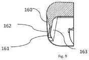
- FIG. 9is a cross-sectional view of a side wall of the talar component of FIG. 3 , viewed from the anterior end.
- proximalgenerally means closer to the heart and the term “distal” generally means farther away from the heart.
- posteriormeans a position towards the rear of the body and the term “anterior” means a position toward the front of the body.
- superiormeans a position closer to the head and the term “inferior” means a position closer to the feet.
- FIG. 1illustrates a simplified side view of the bones of the foot and ankle, including the distal tibia 10 , the talus 20 , and the distal fibula 30 .
- the distal tibia 10 and the proximal talus 20may be arthritic and need replacing with a partial or full joint replacement implant.
- FIG. 2illustrates an example of a full joint replacement implant 100 including a tibial component 40 , a talar component 50 , and a mobile bearing 60 (e.g., typically formed of ultra-high molecular weight polyethylene or other plastic) interposed between the tibial and talar components (e.g., typically formed of metal or the like).
- a mobile bearing 60e.g., typically formed of ultra-high molecular weight polyethylene or other plastic
- the present disclosureincludes a talar component which may be used as a partial joint replacement implant or as part of a total replacement ankle implant.
- FIGS. 3-9show one embodiment of such a talar component 150 for use in a total replacement ankle implant such as implant 100 .
- Talar component 150includes superior and inferior surfaces 152 , 154 respectively, anterior and posterior edges 156 , 158 , respectively, and opposing medial and lateral side walls 160 extending at least partially between the anterior and posterior edges. From the top view, as shown in FIG. 4 , talar component 150 may taper outwardly from posterior edge 158 to anterior edge 156 , such that the distance between side walls 160 is greater nearer to the anterior edge than the posterior edge.
- component 150may be different depending on particular sizes of the implant, such as implants of an intended size for a particular anatomy of a particular patient, and the like.
- shape of talar component 150is designed to cover the talar dome and the medial and lateral facets of the ankle as well as provide for a full range of motion in at least the anterior and posterior directions.
- the superior surface 152 of component 150forms the articulation surface and has a shape complementary to the curvature of the other components of the full joint replacement implant, such as the bearing component, and in the illustrated embodiment, the superior surface is generally convex.
- a raised ridge 165may optionally be positioned on the superior surface 152 and may project proximally from superior surface 152 .
- Ridge 165may extend in the anterior-posterior direction on the superior surface.
- Ridge 165may be positioned anywhere on the superior surface as desired, such as substantially in the medial-lateral center of the superior surface and may further have a generally curved shape. If present, ridge 165 is designed to help constrain the motion of the bearing component in the medial-lateral direction. For example, during plantar flexion (e.g., flexion) or dorsiflexion (e.g., extension) of the ankle implant, ridge 165 would track within a complementary channel in the bearing component.
- inferior surface 154is generally concave to conform to the talar dome of the natural ankle, and the adjacent side walls 160 defines an inferior volume.
- the talar componentis designed to minimize the amount of bone removal during surgery.
- the inferior surfaceis designed to comport with the talar dome as closely as possible, since every anatomy is slightly different, the inferior surface 154 may not conform exactly to the talar dome, which may result in volume(s) of open space between the implant and the bone within the defined inferior volume.
- talar component 150may also include at least one anchor 168 , 170 extending distally from inferior surface 154 to a distal tip.
- two anchors 168are positioned spaced apart near anterior edge 156
- two anchors 168are positioned spaced apart near posterior edge 158
- one anchor 170is positioned substantially centrally on the inferior surface 154 .
- This positioning of the anchorsis substantially symmetrical in the lateral-medial direction, which may help to minimize rocking or tilting of the talar component relative to the talus 20 .
- anchor 170is larger in size than anchors 168 ; however, in other embodiments, the anchors may be any size relative to each other.
- anchor 170may be the same size or smaller than anchors 168 , and anchors 168 may all be different sizes relative to each other.
- Anchors 168 , 170aid in the fixation of talar component 150 to the bone, and may particularly assist in initial fixation.
- talar component 150may include more or less anchors arranged in a variety of positions on the inferior surface 154 , and may not include any anchors.
- the illustrated anchors 168 , 170are star-shaped, each anchor may have any shape desired.
- the illustrated anchorsextend along axes that are generally parallel to one another and perpendicular to the component 150 body, each anchor may extend in any direction relative to the component body and/or one another as desired.
- each side wall 160extends to and terminate at distal bone-cutting edges 161 .
- each side wall 160has a thickness, measured from outer surface 162 to inner surface 163 of the side walls, the thickness tapering to form bone-cutting edges 161 .
- Bone-cutting edges 161may have a sharpness capable of driving into bone, e.g., functioning as self-cutting edges.
- Edges 161may be any type of edge that enables the edge to cut or drive into the bone, e.g. knife-edge, serrated, etc.
- Edges 161 and side walls 160may drive into the bone to provide a flush fit with the talus with substantially little to no clearance or space between side walls 160 and the talus.
- the bone contacted by edges 161may be the natural talus or could be the prepared cut surfaces of the talus, as discussed below.
- the fitis flush such that substantially all of side walls 160 (e.g., along length of side walls 160 ) of talar component 150 maintains contact with the talus after implantation which may form a seal to prevent synovial fluid from flowing under talar component 150 into any volume of open space which may be present between the bone and inferior surface 154 due to differences between the shape of the inferior surface 154 and the talus 20 , as discussed above.
- the prevention of synovial fluid from seeping under the implantmay provide greater fixation of the implant to the bone and increases the longevity of the implant within the patient. Further, the fit between edges 161 and the bone 20 may supplement fixation by anchors 168 , 170 , or in some instances, could be sufficiently secure such that anchors 168 , 170 need not be present on the component 150 .
- edges 161 and bone 20may be particularly strong in instances where bone-cutting edges 161 could facilitate osteointegration between the talar component 150 and the bone.
- the anchorage of the talar component 150and in particular the anchorage of edges 161 , may enable the formation of bony tissue around the component to provide greater structural and functional connection between the component and the bone.
- one or both of side walls 160may extend further distally than in the illustrated embodiment.
- one or both of the bone-cutting edges 161may be positioned further distally, relative to the inferior surface 154 of the talar component 150 such that the edges 161 may extend deeper into the talus 20 which may provide for increased fixation and increased surface area for potential osteointegration, as discussed further below.
- talar component 150may also include sharp bone-cutting edges on anterior and posterior edges 156 , 158 (or, such cutting surface could be in place of edges 161 , whereby medial/lateral walls 160 do not include cutting edges). In instances where all four sides 156 , 158 , 160 include cutting edges, such a talar component may have still further engagement ability with the talus to provide for improved sealing of any volume of open space between the inferior surface 154 and the bone 20 , and further, could result in osteointegration around the perimeter of the component 150 .
- Talar component 150may be comprised of metal, such as titanium, ceramic, glass, polymer, or any other material known for use in the human body.
- the component 150may also comprise one or more surface treatments, on any or all of inferior surface 154 , edges 156 , 158 and side walls 160 , to encourage biological fixation, such as porous coating, plasma spray coating, e.g. titanium plasma spray coating, hydroxyapatite, or tricalcium phosphate.
- the present disclosurealso includes a method of implanting talar component 150 on a prepared talus.
- the methodgenerally includes cutting at least medial and lateral cuts on talus 20 to form a prepared talus, digging a bone-cutting edge 161 of a side wall 160 into one of the medial and lateral cuts and digging the second bone-cutting edge 161 of the second side wall into the other of the medial and lateral cuts.
- the medial and lateral cutsmay be oversized to provide greater space for the bone-cutting edges to dig into the cut to form a seal between the side walls and the bone.
- the present disclosuremay also include various systems and kits based on the components discussed above. While it is envisioned that these various components may be utilized, packaged, sold, or designed in any number of systems and kits, representative embodiments will be discussed in detail below.
- the present disclosurecan include a kit which can be packaged in a single package as a system or in multiple packages that can be selected as needed by the operator to form a system.
- a kitmay include at least one talar component 150 , at least one tibial component, such as tibial component 40 , and at least one mobile bearing, such as bearing 60 .
- Any combination of components including the talar componentmay be included in a single package or in separate packaging which are later brought together as a kit. If multiple components of any of the specific components are present, such components may differ in size, material, configuration, and the like, such that the operator can select a particular component from a variety of available components depending on need based on surrounding anatomy, bone size, bone density, and the like.
- Any such kitmay also include a surgical procedure which may include instructions or protocol for using the components and may include aspects of any of the above-discussed embodiments, though other variations are also envisioned within the scope of the present disclosure.
- the present disclosureincludes a system for the repair of an ankle including at least one talar component, at least one mobile bearing, and at least one tibial component, and a surgical procedure.
- the surgical proceduremay include instructions or protocol for using the components and may include aspects of any of the above-discussed embodiments, though other variations are also envisioned within the scope of the present disclosure.
Landscapes
- Health & Medical Sciences (AREA)
- Orthopedic Medicine & Surgery (AREA)
- Transplantation (AREA)
- Vascular Medicine (AREA)
- Oral & Maxillofacial Surgery (AREA)
- Engineering & Computer Science (AREA)
- Biomedical Technology (AREA)
- Heart & Thoracic Surgery (AREA)
- Cardiology (AREA)
- Life Sciences & Earth Sciences (AREA)
- Animal Behavior & Ethology (AREA)
- General Health & Medical Sciences (AREA)
- Public Health (AREA)
- Veterinary Medicine (AREA)
- Physical Education & Sports Medicine (AREA)
- Prostheses (AREA)
Abstract
Description
Claims (14)
Priority Applications (2)
| Application Number | Priority Date | Filing Date | Title |
|---|---|---|---|
| US16/137,834US11013607B2 (en) | 2017-09-22 | 2018-09-21 | Talar ankle implant |
| US17/328,306US20210338448A1 (en) | 2017-09-22 | 2021-05-24 | Talar Ankle Implant |
Applications Claiming Priority (2)
| Application Number | Priority Date | Filing Date | Title |
|---|---|---|---|
| US201762562007P | 2017-09-22 | 2017-09-22 | |
| US16/137,834US11013607B2 (en) | 2017-09-22 | 2018-09-21 | Talar ankle implant |
Related Child Applications (1)
| Application Number | Title | Priority Date | Filing Date |
|---|---|---|---|
| US17/328,306DivisionUS20210338448A1 (en) | 2017-09-22 | 2021-05-24 | Talar Ankle Implant |
Publications (2)
| Publication Number | Publication Date |
|---|---|
| US20190091032A1 US20190091032A1 (en) | 2019-03-28 |
| US11013607B2true US11013607B2 (en) | 2021-05-25 |
Family
ID=63678501
Family Applications (2)
| Application Number | Title | Priority Date | Filing Date |
|---|---|---|---|
| US16/137,834Active2039-02-14US11013607B2 (en) | 2017-09-22 | 2018-09-21 | Talar ankle implant |
| US17/328,306AbandonedUS20210338448A1 (en) | 2017-09-22 | 2021-05-24 | Talar Ankle Implant |
Family Applications After (1)
| Application Number | Title | Priority Date | Filing Date |
|---|---|---|---|
| US17/328,306AbandonedUS20210338448A1 (en) | 2017-09-22 | 2021-05-24 | Talar Ankle Implant |
Country Status (4)
| Country | Link |
|---|---|
| US (2) | US11013607B2 (en) |
| EP (2) | EP3459501B8 (en) |
| DK (1) | DK3769724T3 (en) |
| ES (2) | ES2832739T3 (en) |
Cited By (2)
| Publication number | Priority date | Publication date | Assignee | Title |
|---|---|---|---|---|
| US11690727B2 (en)* | 2017-08-29 | 2023-07-04 | Corentec Co., Ltd. | Artificial ankle joint tibia component |
| US12268609B2 (en) | 2013-03-07 | 2025-04-08 | Howmedica Osteonics Corp. | Method of manufacturing a tibial implant |
Families Citing this family (3)
| Publication number | Priority date | Publication date | Assignee | Title |
|---|---|---|---|---|
| WO2020013901A2 (en) | 2018-04-24 | 2020-01-16 | Paragon 28, Inc. | Implants and methods of use and assembly |
| CN110013360A (en)* | 2019-04-26 | 2019-07-16 | 中国人民解放军联勤保障部队第九二〇医院 | A high-conformity tibia-talus bionic cooperating joint |
| CN110013364A (en)* | 2019-04-26 | 2019-07-16 | 中国人民解放军联勤保障部队第九二〇医院 | A bionic fixation-resistant talus replacement part for the upper end of the talus with high conformability |
Citations (223)
| Publication number | Priority date | Publication date | Assignee | Title |
|---|---|---|---|---|
| US1505106A (en) | 1921-08-18 | 1924-08-19 | Alexander Bernhard Drager | Burner for the autogenous cutting of metals |
| US3839742A (en) | 1972-07-22 | 1974-10-08 | Link W | Prosthetic device for the tarsal joint |
| US3975778A (en) | 1975-07-14 | 1976-08-24 | Newton Iii St Elmo | Total ankle arthroplasty |
| US3987500A (en) | 1976-01-28 | 1976-10-26 | Schlein Allen P | Surgically implantable total ankle prosthesis |
| US4021864A (en) | 1976-04-14 | 1977-05-10 | The Regents Of The University Of California | Ankle prosthesis |
| US4069518A (en) | 1976-08-31 | 1978-01-24 | Groth Jr Harry E | Total ankle prosthesis |
| US4156944A (en) | 1976-11-15 | 1979-06-05 | Sulzer Brothers Limited | Total ankle prosthesis |
| US4166292A (en) | 1977-09-08 | 1979-09-04 | Carbomedics, Inc. | Stress reinforced artificial joint prostheses |
| US4229839A (en) | 1977-11-16 | 1980-10-28 | Lord Corporation | Joint prosthesis |
| US4232404A (en) | 1977-07-18 | 1980-11-11 | National Research Development Corporation | Endoprosthetic ankle joint |
| US4289123A (en) | 1980-03-31 | 1981-09-15 | Dunn Harold K | Orthopedic appliance |
| US4301552A (en) | 1977-05-20 | 1981-11-24 | Wright Manufacturing Company | Endoprosthetic joint device |
| US4499900A (en) | 1982-11-26 | 1985-02-19 | Wright State University | System and method for treating paralyzed persons |
| US4501269A (en) | 1981-12-11 | 1985-02-26 | Washington State University Research Foundation, Inc. | Process for fusing bone joints |
| US4524766A (en) | 1982-01-07 | 1985-06-25 | Petersen Thomas D | Surgical knee alignment method and system |
| US4569352A (en) | 1983-05-13 | 1986-02-11 | Wright State University | Feedback control system for walking |
| US4570927A (en) | 1983-12-15 | 1986-02-18 | Wright State University | Therapeutic device |
| US4586495A (en) | 1984-07-02 | 1986-05-06 | Wright State University | Therapy system for acute patient care |
| US4655778A (en) | 1985-08-12 | 1987-04-07 | Harrington Arthritis Research Center | Joint prosthesis |
| US4697808A (en) | 1985-05-16 | 1987-10-06 | Wright State University | Walking assistance system |
| US4711242A (en) | 1986-02-18 | 1987-12-08 | Wright State University | Control system for knee joint |
| US4978357A (en)* | 1987-06-12 | 1990-12-18 | Mecron Medizinische Produkte Gmbh | Endoprosthesis |
| US4990161A (en) | 1984-03-16 | 1991-02-05 | Kampner Stanley L | Implant with resorbable stem |
| US5020519A (en) | 1990-12-07 | 1991-06-04 | Zimmer, Inc. | Sagittal approximator |
| US5041139A (en) | 1989-04-25 | 1991-08-20 | Branemark Per Ingvar | Anchoring element for supporting a joint mechanism of an ankle, hip or other reconstructed joint |
| US5063937A (en) | 1990-09-12 | 1991-11-12 | Wright State University | Multiple frequency bio-impedance measurement system |
| US5074285A (en) | 1989-11-20 | 1991-12-24 | Wright Linear Pump, Inc. | Thermal applicator method |
| US5122144A (en) | 1989-09-26 | 1992-06-16 | Kirschner Medical Corporation | Method and instrumentation for unicompartmental total knee arthroplasty |
| US5219364A (en) | 1991-09-12 | 1993-06-15 | Wright & Filippis, Inc. | Continuous one-piece prosthesis |
| EP0554959A1 (en) | 1992-02-06 | 1993-08-11 | Bristol-Myers Squibb Company | Apparatus for milling bone |
| US5326365A (en) | 1992-04-10 | 1994-07-05 | Alvine Franklin G | Ankle implant |
| US5431653A (en) | 1993-07-06 | 1995-07-11 | Callaway; George H. | Knee joint flexion-gap distraction device |
| US5514139A (en) | 1994-09-02 | 1996-05-07 | Hudson Surgical Design, Inc. | Method and apparatus for femoral resection |
| US5571109A (en) | 1993-08-26 | 1996-11-05 | Man Ceramics Gmbh | System for the immobilization of vertebrae |
| US5571184A (en) | 1995-06-07 | 1996-11-05 | Wright Medical Technology, Inc. | Graft fixation device and method of using |
| US5630820A (en) | 1994-12-05 | 1997-05-20 | Sulzer Orthopedics Inc. | Surgical bicompartmental tensiometer for revision knee surgery |
| WO1997023172A2 (en) | 1995-12-26 | 1997-07-03 | Musculographics, Inc. | Computer-assisted surgical system |
| US5649929A (en) | 1995-07-10 | 1997-07-22 | Callaway; George Hadley | Knee joint flexion-gap distraction device |
| US5662656A (en) | 1995-12-08 | 1997-09-02 | Wright Medical Technology, Inc. | Instrumentation and method for distal femoral sizing, and anterior and distal femoral resections |
| US5766259A (en) | 1995-03-14 | 1998-06-16 | Sammarco; Giacomo J. | Total ankle prosthesis and method |
| US5810827A (en) | 1994-09-02 | 1998-09-22 | Hudson Surgical Design, Inc. | Method and apparatus for bony material removal |
| US5824106A (en) | 1996-04-11 | 1998-10-20 | Tornier Sa | Ankle prosthesis |
| US5885299A (en) | 1994-09-15 | 1999-03-23 | Surgical Dynamics, Inc. | Apparatus and method for implant insertion |
| FR2770393A1 (en) | 1997-10-31 | 1999-05-07 | Protek Sa | FEMORAL CUTTING DEVICE FOR PLACING A TOTAL RECOVERY KNEE PROSTHESIS |
| US5916216A (en) | 1995-06-07 | 1999-06-29 | Wright Medical Technology, Inc. | Graft fixation devices |
| US5993487A (en) | 1994-12-29 | 1999-11-30 | Wright & Filippis | Integrated keel-pylon prosthesis |
| WO1999065403A1 (en) | 1998-06-15 | 1999-12-23 | Sulzer Orthopedics Inc. | Nested bone cutting block |
| US6053945A (en) | 1997-09-25 | 2000-04-25 | Johnson & Johnson Professional, Inc. | Joint prosthesis having controlled rotation |
| US6090114A (en) | 1997-02-10 | 2000-07-18 | Stryker Howmedica Osteonics Corp. | Tibial plateau resection guide |
| US6099571A (en) | 1997-07-16 | 2000-08-08 | Knapp; John G. | Joint prosthesis |
| US6174314B1 (en) | 1998-12-15 | 2001-01-16 | David D. Waddell | In situ pattellar resection guide |
| US6183519B1 (en) | 1997-03-10 | 2001-02-06 | Tornier Sa | Ankle prosthesis |
| US6245109B1 (en) | 1999-11-18 | 2001-06-12 | Intellijoint Systems, Ltd. | Artificial joint system and method utilizing same for monitoring wear and displacement of artificial joint members |
| US20010029377A1 (en) | 1998-10-02 | 2001-10-11 | Synthes U.S.A. | Spinal disc space distractor |
| US6409767B1 (en) | 1999-11-05 | 2002-06-25 | European Foot Platform | Ankle prosthesis |
| US20020116009A1 (en) | 2000-05-08 | 2002-08-22 | Fraser Robert D. | Medical installation tool |
| US20020143343A1 (en) | 2001-03-27 | 2002-10-03 | Surgical Dynamics, Inc. | Method and apparatus for spinal implant insertion |
| US6482236B2 (en) | 2000-10-12 | 2002-11-19 | Matthew J. Habecker | Prosthetic ankle joint mechanism |
| US6520967B1 (en) | 1999-10-20 | 2003-02-18 | Cauthen Research Group, Inc. | Spinal implant insertion instrument for spinal interbody prostheses |
| US6551316B1 (en) | 2001-03-02 | 2003-04-22 | Beere Precision Medical Instruments, Inc. | Selective compression and distraction instrument |
| US6554837B1 (en) | 1998-06-29 | 2003-04-29 | Plus Endoprothetik Ag | Device and method for inserting a prosthetic knee |
| US6610095B1 (en) | 2000-01-30 | 2003-08-26 | Diamicron, Inc. | Prosthetic joint having substrate surface topographical featurers and at least one diamond articulation surface |
| US20030212403A1 (en) | 2002-05-10 | 2003-11-13 | Swanson Todd V. | Method and apparatus for minimally invasive knee arthroplasty |
| US6663669B1 (en) | 1999-10-22 | 2003-12-16 | Mark A Reiley | Ankle replacement system |
| US6673116B2 (en) | 1999-10-22 | 2004-01-06 | Mark A. Reiley | Intramedullary guidance systems and methods for installing ankle replacement prostheses |
| US6686437B2 (en) | 2001-10-23 | 2004-02-03 | M.M.A. Tech Ltd. | Medical implants made of wear-resistant, high-performance polyimides, process of making same and medical use of same |
| US20040030399A1 (en) | 2000-05-22 | 2004-02-12 | Joseph-Guy Asencio | Articulation prosthesis |
| US6699289B2 (en) | 2001-12-31 | 2004-03-02 | Depuy Orthopaedics, Inc. | Augmented glenoid component having an interrupted surface and associated method for securing the augmented glenoid component to a glenoid surface of a scapula |
| US20040102785A1 (en) | 2002-11-27 | 2004-05-27 | Hodorek Robert A. | Method and apparatus for achieving correct limb alignment in unicondylar knee arthroplasty |
| US20040117019A1 (en) | 2000-08-30 | 2004-06-17 | Trieu Hai H. | Method and apparatus for delivering an intervertebral disc implant |
| US20040122519A1 (en) | 2002-12-20 | 2004-06-24 | Wiley Roy C. | Prosthetic glenoid |
| US20040167631A1 (en) | 2003-02-21 | 2004-08-26 | Kenny Luchesi | Fixation surface for ankle prosthesis |
| US20040186585A1 (en) | 2003-03-21 | 2004-09-23 | Lawrence Feiwell | Sphere-on-sphere ankle prosthesis |
| EP1468652A1 (en) | 2003-04-16 | 2004-10-20 | Paul M. Tsou | Apparatus for endoscopic spinal surgery |
| US20040220582A1 (en) | 2001-01-12 | 2004-11-04 | Arnold Keller | Surgical instrument for inserting an intervertebral endoprosthesis |
| US20040249388A1 (en) | 1996-07-31 | 2004-12-09 | Michelson Gary K. | Distractor with opening |
| US20050004676A1 (en) | 2002-06-27 | 2005-01-06 | Schon Lew C. | Semi-constrained ankle joint prosthesis and its method of implantation |
| US20050027360A1 (en) | 2003-08-01 | 2005-02-03 | Webb Scott A. | Spinal implant |
| US6852130B2 (en) | 2002-03-08 | 2005-02-08 | Waldemar Link Gmbh & Co. Kg | Ankle-joint endoprosthesis |
| US20050033442A1 (en) | 1999-09-08 | 2005-02-10 | John Fisher | Combination of material for joint prothesis |
| US20050049710A1 (en) | 2003-08-28 | 2005-03-03 | O'driscoll Shawn W. | Prosthesis for partial replacement of an articulating surface on bone |
| US6863691B2 (en) | 2002-04-29 | 2005-03-08 | Timothy J. Short | Ankle implant |
| US20050055028A1 (en) | 1994-09-02 | 2005-03-10 | Hudson Surgical Design, Inc. | Methods and apparatus for femoral and tibial resection |
| US6866683B2 (en) | 2002-12-13 | 2005-03-15 | Medicine Lodge, Inc. | Modular implant for joint reconstruction and method of use |
| US6887276B2 (en) | 2002-12-13 | 2005-05-03 | Medicine Lodge, Inc | Modular implant for joint reconstruction and method of use |
| US20050113842A1 (en) | 2002-05-06 | 2005-05-26 | Rudolf Bertagnoli | Instrumentation and methods for preparation of an intervertebral space |
| US20050119665A1 (en) | 2001-10-29 | 2005-06-02 | Arnold Keller | Instrumentation for insertion of an inter-vertebral prosthesis |
| US6911047B2 (en) | 2000-03-17 | 2005-06-28 | Depuy Orthopaedics, Inc. | Apparatus and method for securing a cementless glenoid component to a glenoid surface of a scapula |
| US20050165408A1 (en) | 2004-01-26 | 2005-07-28 | Puno Rolando M. | Methods and instrumentation for inserting intervertebral grafts and devices |
| US6926739B1 (en) | 1999-05-13 | 2005-08-09 | John J. O'Connor | Prosthesis device for human articulations, in particular for the ankle articulation |
| US6939380B2 (en) | 2002-12-23 | 2005-09-06 | Depuy Products, Inc. | Mobile talar component for total ankle replacement implant |
| US20050245928A1 (en) | 2004-05-03 | 2005-11-03 | Innovative Spinal Technologies | System and method for displacement of bony structures |
| US20050288792A1 (en) | 2004-06-23 | 2005-12-29 | Landes Mark D | Modular ankle prosthesis and associated method |
| US20060004377A1 (en) | 2003-07-15 | 2006-01-05 | Cervitech, Inc. | Insertion instrument for cervical prostheses |
| US20060041311A1 (en) | 2004-08-18 | 2006-02-23 | Mcleer Thomas J | Devices and methods for treating facet joints |
| US7011687B2 (en) | 2003-01-06 | 2006-03-14 | Depuy Products, Inc. | Ankle prosthesis with a front loading bearing and associated method |
| US20060100634A1 (en) | 2004-11-09 | 2006-05-11 | Sdgi Holdings, Inc. | Technique and instrumentation for measuring and preparing a vertebral body for device implantation using datum block |
| US7060074B2 (en) | 2001-11-28 | 2006-06-13 | Wright Medical Technology, Inc. | Instrumentation for minimally invasive unicompartmental knee replacement |
| US20060136058A1 (en) | 2004-12-17 | 2006-06-22 | William Pietrzak | Patient specific anatomically correct implants to repair or replace hard or soft tissue |
| US20060142870A1 (en) | 2004-08-19 | 2006-06-29 | Shawn Robinson | Modular total ankle prosthesis apparatuses, systems and methods, and systems and methods for bone resection and prosthetic implantation |
| US20060149278A1 (en) | 2004-11-24 | 2006-07-06 | Abdou Amy M | Devices and methods for inter-vertebral orthopedic device placement |
| US20060195116A1 (en) | 2005-02-25 | 2006-08-31 | Fox Michael D | D-Tail patellar bone tunneling system |
| US7118580B1 (en) | 1999-09-14 | 2006-10-10 | Spine Solutions Inc. | Instrument for inserting intervertebral implants |
| US20060241634A1 (en) | 2005-02-21 | 2006-10-26 | Wright Medical Technology, Inc. | Instruments for minimally invasive surgery total knee arthroplasty |
| US20060247788A1 (en) | 2005-03-31 | 2006-11-02 | The Regents Of The University Of California | Total ankle arthroplasty |
| US7141053B2 (en) | 2001-11-28 | 2006-11-28 | Wright Medical Technology, Inc. | Methods of minimally invasive unicompartmental knee replacement |
| US20070038303A1 (en) | 2006-08-15 | 2007-02-15 | Ebi, L.P. | Foot/ankle implant and associated method |
| US20070088442A1 (en) | 2005-10-14 | 2007-04-19 | Microchips, Inc. | Passive wear-indicating sensor for implantable prosthetic device |
| US20070123901A1 (en) | 2000-10-20 | 2007-05-31 | Foley Kevin T | Methods and instruments for interbody surgical techniques |
| US20070135924A1 (en) | 2005-12-14 | 2007-06-14 | Verhoogen Alex R | Joint replacement prosthesis, joint replacement mounting stud and method |
| US20070173944A1 (en) | 2005-12-12 | 2007-07-26 | Waldemar Link Gmbh & Co. Kg | Endoprosthesis with intermediate part |
| WO2007092728A1 (en) | 2006-02-02 | 2007-08-16 | Zimmer Technology, Inc. | Hip stem centralizer datum guide and method |
| US20070191857A1 (en) | 2006-01-31 | 2007-08-16 | Sdgi Holdings, Inc. | Spinal disc replacement surgical instrument and methods for use in spinal disc replacement |
| WO2007103826A2 (en) | 2006-03-02 | 2007-09-13 | Talus Medical, Inc. | Bone prosthesis |
| US20070233140A1 (en) | 2006-02-27 | 2007-10-04 | Biomet Manufacturing Corp. | Femoral adjustment device and associated method |
| US7297165B1 (en) | 1999-11-02 | 2007-11-20 | Ardemed Innovations Limited | Joint prostheses |
| US20080015603A1 (en) | 2006-06-30 | 2008-01-17 | Howmedica Osteonics Corp. | High tibial osteotomy system |
| US7323012B1 (en) | 2004-03-17 | 2008-01-29 | Biomet Manufacturing Corp. | Ankle implant |
| US7361194B2 (en) | 2004-10-14 | 2008-04-22 | Wright Medical Technology, Inc. | Metallic bearings for joint replacement |
| US20080097617A1 (en) | 2004-11-08 | 2008-04-24 | Alphamed Medizintechnik Fischer Gmbh | Ankle Joint Endoprosthesis Elements |
| US20080109081A1 (en) | 2003-10-22 | 2008-05-08 | Qi-Bin Bao | Joint Arthroplasty Devices Having Articulating Members |
| WO2008076559A1 (en) | 2006-12-15 | 2008-06-26 | Synthes Usa, Llc | Osteotomy guide and method of cutting the medial distal tibia employing the same |
| WO2008078082A2 (en) | 2006-12-23 | 2008-07-03 | Corin Limited | Improvements in and relating to an ankle prosthesis |
| US20080167655A1 (en) | 2007-01-05 | 2008-07-10 | Jeffrey Chun Wang | Interspinous implant, tools and methods of implanting |
| US20080177275A1 (en) | 2006-12-01 | 2008-07-24 | Charles Wing | Interbody distractor |
| US20080177272A1 (en) | 2005-03-21 | 2008-07-24 | Zucherman James F | Interspinous process implant having deployable wing and method of implantation |
| US7419491B2 (en) | 1997-09-18 | 2008-09-02 | Medidea, Llc | Bone-conserving orthopedic instrumentation and appliances |
| US20080215156A1 (en) | 2004-06-30 | 2008-09-04 | Synergy Disc Replacement | Joint Prostheses |
| US20080269756A1 (en) | 2007-04-27 | 2008-10-30 | Spinemedica, Inc. | Surgical instruments for spinal disc implants and related methods |
| US20080275452A1 (en) | 2001-05-25 | 2008-11-06 | Conformis, Inc. | Surgical Cutting Guide |
| US20080306605A1 (en) | 2006-01-20 | 2008-12-11 | Hasselman Carl T | Method of Preparing an Ankle Joint for Replacement, Joint Prosthesis, and Cutting Alignmnet Apparatus for Use in Performing an Arthroplasty Procedure |
| US7465303B2 (en) | 2004-04-22 | 2008-12-16 | Wright Medical Technology, Inc. | External fixation assembly |
| US20080312745A1 (en) | 2007-06-12 | 2008-12-18 | Waldemar Link Gmbh & Co. Kg | Endoprosthesis with convex configuration |
| US7468075B2 (en) | 2001-05-25 | 2008-12-23 | Conformis, Inc. | Methods and compositions for articular repair |
| WO2008157415A1 (en) | 2007-06-13 | 2008-12-24 | Peter Marlow | Animated artificial flower |
| US7470273B2 (en) | 2004-06-25 | 2008-12-30 | Ebi, Llc | Tool for intervertebral implant manipulation |
| US20090018665A1 (en) | 2007-07-09 | 2009-01-15 | Exploramed Nc4, Inc. | Surgical implantation method and devices for an extra-articular mechanical energy absorbing apparatus |
| US20090030422A1 (en) | 2007-07-23 | 2009-01-29 | Depuy Spine, Inc. | Implant insertion device and method |
| WO2009015009A1 (en) | 2007-07-20 | 2009-01-29 | Talus Medical, Inc. | Methods and devices for deploying biological implants |
| US7485147B2 (en) | 2004-02-13 | 2009-02-03 | Pappas Michael J | Ankle prosthesis including tibial component having peripheral wall for preventing the formation of bone cysts |
| US7491205B1 (en) | 1988-06-13 | 2009-02-17 | Warsaw Orthopedic, Inc. | Instrumentation for the surgical correction of human thoracic and lumbar spinal disease from the lateral aspect of the spine |
| US7510557B1 (en) | 2000-01-14 | 2009-03-31 | Bonutti Research Inc. | Cutting guide |
| US7534246B2 (en) | 2005-03-14 | 2009-05-19 | Inbone Technologies, Inc. | Ankle replacement system |
| US7534270B2 (en) | 2003-09-03 | 2009-05-19 | Integra Lifesciences Corporation | Modular total ankle prosthesis apparatuses and methods |
| US20090132047A1 (en) | 2004-11-30 | 2009-05-21 | Mansmann Kevin A | Anchoring systems and interfaces for flexible surgical implants for replacing cartilage |
| US20090138021A1 (en) | 2005-09-30 | 2009-05-28 | Callum Colquhoun | Instrument assembly for use in knee joint replacement surgery |
| US20090234362A1 (en) | 2008-03-12 | 2009-09-17 | Spinal Elements, Inc. | Offset opposing arm spinal implant distractor/inserter |
| US20090270869A1 (en) | 2005-09-30 | 2009-10-29 | Callum Colquhoun | Distractor instrument |
| US20090275951A1 (en) | 2008-04-30 | 2009-11-05 | Arcenio Gregory B | Percutaneous discectomy and endplate preparation tool |
| US20090276052A1 (en) | 2008-04-30 | 2009-11-05 | Exploramed Nc4, Inc. | Ball and socket assembly |
| US7618451B2 (en) | 2001-05-25 | 2009-11-17 | Conformis, Inc. | Patient selectable joint arthroplasty devices and surgical tools facilitating increased accuracy, speed and simplicity in performing total and partial joint arthroplasty |
| US7625409B2 (en) | 2003-10-14 | 2009-12-01 | University Of Iowa Research Foundation | Ankle prosthesis |
| US7628818B2 (en) | 2007-09-28 | 2009-12-08 | Depuy Products, Inc. | Fixed-bearing knee prosthesis having interchangeable components |
| US20090306675A1 (en) | 2008-05-30 | 2009-12-10 | Wright Medical Technology, Inc. | Drill guide assembly |
| US20090306781A1 (en) | 2006-02-06 | 2009-12-10 | Masayuki Kyomoto | High Wear-Resistant Bearing Material and Artificial Joint Replacement Using the Same |
| US20090306671A1 (en) | 2008-06-06 | 2009-12-10 | Providence Medical Technology, Inc. | Facet joint implants and delivery tools |
| US7632279B2 (en) | 2004-12-27 | 2009-12-15 | Howmedica Osteonics Corp. | Patella resection clamp |
| WO2009158522A1 (en) | 2008-06-25 | 2009-12-30 | Small Bone Innovations, Inc. | Surgical instrumentation and methods of use for implanting a prothesis |
| US20100023066A1 (en) | 2002-06-21 | 2010-01-28 | Depuy Products, Inc. | Method for Removal of Bone |
| US20100057216A1 (en) | 2008-07-23 | 2010-03-04 | Jamy Gannoe | System and method for joint resurfacing with dynamic fixation |
| US20100100097A1 (en) | 2008-10-22 | 2010-04-22 | Wright Medical Technology, Inc. | Instruments for preparing bone implants |
| US20100191244A1 (en) | 2007-03-23 | 2010-07-29 | Derrick White | Surgical templates |
| US20100198355A1 (en) | 2003-08-27 | 2010-08-05 | Link America, Inc. | Ankle-joint endoprosthesis |
| US20100217338A1 (en) | 2009-02-24 | 2010-08-26 | Wright Medical Technology, Inc. | Patient Specific Surgical Guide Locator and Mount |
| US7842092B2 (en) | 2006-03-14 | 2010-11-30 | Mako Surgical Corp. | Prosthetic device and system and method for implanting prosthetic device |
| US20110009964A1 (en) | 2008-02-28 | 2011-01-13 | Biopoly, Llc | Partial joint resurfacing implant, instrumentation and method |
| US20110035019A1 (en) | 2009-07-09 | 2011-02-10 | Wright State University | Total ankle replacement system |
| US7914583B2 (en) | 2006-08-22 | 2011-03-29 | New York Society For The Ruptured And Crippled Maintaining The Hospital For Special Surgey | Wrist implants |
| US20110112542A1 (en) | 2009-11-10 | 2011-05-12 | Wright Medical Technology, Inc. | Adjustable revision guide |
| US20110118792A1 (en) | 2009-11-17 | 2011-05-19 | Wright Medical Technology, Inc. | Method and device for insertion of orthopedic fixation pin with blind hole |
| US20110125275A1 (en) | 2009-11-16 | 2011-05-26 | New York Society For The Ruptured And Crippled Maintaining The Hospital For Special Surgery | Prosthetic condylar joints with articulating bearing surfaces having a translating contact point during rotation thereof |
| US20110172780A1 (en) | 2009-12-31 | 2011-07-14 | John Scheland | Method and apparatus for fusing the bones of a joint |
| US20110295380A1 (en) | 2010-05-28 | 2011-12-01 | Long Jack F | Semi-constrained ankle prosthesis having a rotating bearing insert |
| US20110313469A1 (en) | 2007-03-20 | 2011-12-22 | Wright Medical Technology, Inc. | Bone screw system |
| US20110313532A1 (en) | 2010-06-18 | 2011-12-22 | Jessee Hunt | Bone implant interface system and method |
| US20110320005A1 (en) | 2003-06-27 | 2011-12-29 | Rydell Mark A | System and Method for Ankle Arthroplasty |
| US20120010718A1 (en) | 2010-07-08 | 2012-01-12 | Still Gregory P | Partial ankle joint replacement implant |
| US8114091B2 (en) | 2006-01-24 | 2012-02-14 | Tornier | Surgical instrumentation kit for inserting an ankle prosthesis |
| US8128703B2 (en) | 2007-09-28 | 2012-03-06 | Depuy Products, Inc. | Fixed-bearing knee prosthesis having interchangeable components |
| US20120109326A1 (en) | 2010-11-02 | 2012-05-03 | Perler Adam D | Prosthetic Device with Multi-Axis Dual Bearing Assembly and Methods for Resection |
| US20120130434A1 (en) | 2009-02-24 | 2012-05-24 | Wright Medical Technology, Inc. | Orthopedic surgical guide |
| US8241360B2 (en) | 2002-05-23 | 2012-08-14 | Pioneer Surgical Technology, Inc. | Artificial disc device |
| US8268007B2 (en) | 2009-06-26 | 2012-09-18 | The Cleveland Clinic Foundation | Multi-piece prosthetic joint component |
| US20120245701A1 (en) | 2011-03-24 | 2012-09-27 | Rudolf Zak | Hemi Ankle Implant |
| US8277448B2 (en) | 2007-03-07 | 2012-10-02 | Wright Medical Technology, Inc. | External fixation |
| US8282590B2 (en) | 2009-03-27 | 2012-10-09 | Wright State University | Toe brace designs |
| US20120271314A1 (en) | 2009-02-24 | 2012-10-25 | Wright Medical Technology, Inc. | Orthopedic surgical guide |
| US20120271430A1 (en) | 2011-04-22 | 2012-10-25 | Medicinelodge, Inc. Dba Imds Co-Innovation | Ankle arthroplasty |
| US20130030529A1 (en) | 2011-07-29 | 2013-01-31 | Jessee Hunt | Implant interface system and method |
| US20130041473A1 (en) | 2010-02-19 | 2013-02-14 | Newdeal | Ankle prosthesis with simplified adjustment |
| US20130090739A1 (en) | 2011-09-27 | 2013-04-11 | Linares Medical Devices, Llc | Implantable ankle joint assembly with spherical inter-support |
| US8430930B2 (en) | 2008-12-18 | 2013-04-30 | 4-Web, Inc. | Truss implant |
| US20130116797A1 (en) | 2011-11-04 | 2013-05-09 | Tornier Sas | Surgical instrumentation assembly for positioning an ankle prosthesis |
| US20130123935A1 (en) | 2011-11-03 | 2013-05-16 | Jessee Hunt | Method of length preservation during bone repair |
| US8470047B2 (en) | 2007-09-25 | 2013-06-25 | Depuy (Ireland) | Fixed-bearing knee prosthesis |
| US20130184830A1 (en) | 2007-09-25 | 2013-07-18 | Stephen A. Hazebrouck | Fixed-bearing knee prosthesis having interchangeable components |
| US8496712B2 (en) | 1999-10-22 | 2013-07-30 | Inbone Technologies, Inc. | Systems and methods for installing ankle replacement prostheses |
| US8496713B2 (en) | 2010-12-10 | 2013-07-30 | Globus Medical, Inc. | Spine stabilization device and methods |
| US20130218275A1 (en) | 2012-02-17 | 2013-08-22 | Ervin Caballes | Elastomeric artificial joints and intervertebral prosthesis systems |
| US8556983B2 (en) | 2001-05-25 | 2013-10-15 | Conformis, Inc. | Patient-adapted and improved orthopedic implants, designs and related tools |
| US8585744B2 (en) | 2009-07-14 | 2013-11-19 | Imds Corporation | Joint arthrodesis and arthroplasty |
| US8597361B2 (en) | 2010-11-11 | 2013-12-03 | Bioshift, Llc | Joint implant fixation system |
| US20140107794A1 (en) | 2007-09-25 | 2014-04-17 | Depuy (Ireland) | Prosthesis for cementless fixation |
| US20140128985A1 (en) | 2012-11-07 | 2014-05-08 | Roy W. Sanders | Joint Arthroplasty Systems, Methods, and Components |
| US20140188236A1 (en) | 2012-12-27 | 2014-07-03 | Wright Medical Technology, Inc. | Ankle replacement system and method |
| US8871142B2 (en) | 2008-05-22 | 2014-10-28 | DePuy Synthes Products, LLC | Implants with roughened surfaces |
| US20140336658A1 (en) | 2012-12-27 | 2014-11-13 | Wright Medical Technology, Inc. | Ankle replacement system and method |
| US20140350688A1 (en) | 2012-04-12 | 2014-11-27 | Arthrex, Inc. | Talus surface implant |
| US20150045902A1 (en) | 2011-11-01 | 2015-02-12 | Adam D. Perler | Semi Constrained Polyaxial Endoprosthetic Ankle Joint Replacement Implant |
| US8998991B2 (en) | 2011-02-23 | 2015-04-07 | Globus Medical, Inc. | Six degree spine stabilization devices and methods |
| US20150157339A1 (en) | 2012-12-27 | 2015-06-11 | Wright Medical Technology, Inc. | Ankle replacement system and method |
| US20150157463A1 (en) | 2006-12-08 | 2015-06-11 | DePuy Synthes Products, Inc. | Method of Implanting A Curable Implant Material |
| US9101476B2 (en) | 2009-05-21 | 2015-08-11 | Depuy (Ireland) | Prosthesis with surfaces having different textures and method of making the prosthesis |
| US9144500B2 (en) | 2012-09-20 | 2015-09-29 | Michael G. Harding, Jr. | Ankle replacement devices and methods of making and using the same |
| US9180012B2 (en) | 2010-05-18 | 2015-11-10 | Smith & Nephew, Inc. | Application of diffusion hardened material |
| US20150320567A1 (en) | 2014-05-12 | 2015-11-12 | Integra Lifesciences Corporation | Total Ankle Replacement Prosthesis |
| US9204967B2 (en) | 2007-09-28 | 2015-12-08 | Depuy (Ireland) | Fixed-bearing knee prosthesis having interchangeable components |
| US9216085B2 (en) | 2008-02-28 | 2015-12-22 | Biopoly, Llc | Partial joint resurfacing implant, instrumentation, and method |
| US9237953B2 (en) | 2013-03-15 | 2016-01-19 | Depuy (Ireland) | Mechanical assembly of pegs to prosthesis |
| US20160128842A1 (en)* | 2014-11-07 | 2016-05-12 | Kian-Ming Wong | Talar dome fixation stem |
| US9907561B2 (en) | 2012-12-27 | 2018-03-06 | Wright Medical Technologies, Inc. | Ankle replacement system and method |
| US10106724B2 (en) | 2012-11-19 | 2018-10-23 | 3M Innovative Properties Company | Method of contacting hydrocarbon-bearing formations with fluorinated ionic polymers |
| US20190059918A1 (en)* | 2017-08-24 | 2019-02-28 | Charles Saltzman | Ankle arthroplasty systems and methods |
Family Cites Families (3)
| Publication number | Priority date | Publication date | Assignee | Title |
|---|---|---|---|---|
| US5171276A (en)* | 1990-01-08 | 1992-12-15 | Caspari Richard B | Knee joint prosthesis |
| DE19949890A1 (en)* | 1999-10-15 | 2001-06-07 | Peter Copf | Prosthetic top ankle joint has two parts, two joint surfaces, anchor sections with anchor elements |
| US10856992B2 (en)* | 2016-04-27 | 2020-12-08 | AOD Holdings, LLC | Implant device(s) including tapered protrusions and method(s) for inserting the same into bone |
- 2018
- 2018-09-21USUS16/137,834patent/US11013607B2/enactiveActive
- 2018-09-21ESES18195986Tpatent/ES2832739T3/enactiveActive
- 2018-09-21EPEP18195986.7Apatent/EP3459501B8/enactiveActive
- 2018-09-21EPEP20193876.8Apatent/EP3769724B1/enactiveActive
- 2018-09-21DKDK20193876.8Tpatent/DK3769724T3/enactive
- 2018-09-21ESES20193876Tpatent/ES2913991T3/enactiveActive
- 2021
- 2021-05-24USUS17/328,306patent/US20210338448A1/ennot_activeAbandoned
Patent Citations (292)
| Publication number | Priority date | Publication date | Assignee | Title |
|---|---|---|---|---|
| US1505106A (en) | 1921-08-18 | 1924-08-19 | Alexander Bernhard Drager | Burner for the autogenous cutting of metals |
| US3839742A (en) | 1972-07-22 | 1974-10-08 | Link W | Prosthetic device for the tarsal joint |
| US3975778A (en) | 1975-07-14 | 1976-08-24 | Newton Iii St Elmo | Total ankle arthroplasty |
| US3987500A (en) | 1976-01-28 | 1976-10-26 | Schlein Allen P | Surgically implantable total ankle prosthesis |
| US4021864A (en) | 1976-04-14 | 1977-05-10 | The Regents Of The University Of California | Ankle prosthesis |
| US4069518A (en) | 1976-08-31 | 1978-01-24 | Groth Jr Harry E | Total ankle prosthesis |
| US4156944A (en) | 1976-11-15 | 1979-06-05 | Sulzer Brothers Limited | Total ankle prosthesis |
| US4301552A (en) | 1977-05-20 | 1981-11-24 | Wright Manufacturing Company | Endoprosthetic joint device |
| US4232404A (en) | 1977-07-18 | 1980-11-11 | National Research Development Corporation | Endoprosthetic ankle joint |
| US4166292A (en) | 1977-09-08 | 1979-09-04 | Carbomedics, Inc. | Stress reinforced artificial joint prostheses |
| US4229839A (en) | 1977-11-16 | 1980-10-28 | Lord Corporation | Joint prosthesis |
| US4289123A (en) | 1980-03-31 | 1981-09-15 | Dunn Harold K | Orthopedic appliance |
| US4501269A (en) | 1981-12-11 | 1985-02-26 | Washington State University Research Foundation, Inc. | Process for fusing bone joints |
| US4524766A (en) | 1982-01-07 | 1985-06-25 | Petersen Thomas D | Surgical knee alignment method and system |
| US4499900A (en) | 1982-11-26 | 1985-02-19 | Wright State University | System and method for treating paralyzed persons |
| US4569352A (en) | 1983-05-13 | 1986-02-11 | Wright State University | Feedback control system for walking |
| US4570927A (en) | 1983-12-15 | 1986-02-18 | Wright State University | Therapeutic device |
| US4990161A (en) | 1984-03-16 | 1991-02-05 | Kampner Stanley L | Implant with resorbable stem |
| US4586495A (en) | 1984-07-02 | 1986-05-06 | Wright State University | Therapy system for acute patient care |
| US4697808A (en) | 1985-05-16 | 1987-10-06 | Wright State University | Walking assistance system |
| US4655778A (en) | 1985-08-12 | 1987-04-07 | Harrington Arthritis Research Center | Joint prosthesis |
| US4711242A (en) | 1986-02-18 | 1987-12-08 | Wright State University | Control system for knee joint |
| US4978357A (en)* | 1987-06-12 | 1990-12-18 | Mecron Medizinische Produkte Gmbh | Endoprosthesis |
| US7491205B1 (en) | 1988-06-13 | 2009-02-17 | Warsaw Orthopedic, Inc. | Instrumentation for the surgical correction of human thoracic and lumbar spinal disease from the lateral aspect of the spine |
| US5041139A (en) | 1989-04-25 | 1991-08-20 | Branemark Per Ingvar | Anchoring element for supporting a joint mechanism of an ankle, hip or other reconstructed joint |
| US5122144A (en) | 1989-09-26 | 1992-06-16 | Kirschner Medical Corporation | Method and instrumentation for unicompartmental total knee arthroplasty |
| US5074285A (en) | 1989-11-20 | 1991-12-24 | Wright Linear Pump, Inc. | Thermal applicator method |
| US5063937A (en) | 1990-09-12 | 1991-11-12 | Wright State University | Multiple frequency bio-impedance measurement system |
| US5020519A (en) | 1990-12-07 | 1991-06-04 | Zimmer, Inc. | Sagittal approximator |
| US5219364A (en) | 1991-09-12 | 1993-06-15 | Wright & Filippis, Inc. | Continuous one-piece prosthesis |
| US5336270A (en) | 1991-09-12 | 1994-08-09 | Wright & Filippis, Inc. | Continuous one-piece prosthesis |
| EP0554959A1 (en) | 1992-02-06 | 1993-08-11 | Bristol-Myers Squibb Company | Apparatus for milling bone |
| US5344423A (en) | 1992-02-06 | 1994-09-06 | Zimmer, Inc. | Apparatus and method for milling bone |
| US5486180A (en) | 1992-02-06 | 1996-01-23 | Zimmer, Inc. | Apparatus for milling bone |
| US5326365A (en) | 1992-04-10 | 1994-07-05 | Alvine Franklin G | Ankle implant |
| US5431653A (en) | 1993-07-06 | 1995-07-11 | Callaway; George H. | Knee joint flexion-gap distraction device |
| US5571109A (en) | 1993-08-26 | 1996-11-05 | Man Ceramics Gmbh | System for the immobilization of vertebrae |
| US5514139A (en) | 1994-09-02 | 1996-05-07 | Hudson Surgical Design, Inc. | Method and apparatus for femoral resection |
| US20050055028A1 (en) | 1994-09-02 | 2005-03-10 | Hudson Surgical Design, Inc. | Methods and apparatus for femoral and tibial resection |
| US5810827A (en) | 1994-09-02 | 1998-09-22 | Hudson Surgical Design, Inc. | Method and apparatus for bony material removal |
| US5885299A (en) | 1994-09-15 | 1999-03-23 | Surgical Dynamics, Inc. | Apparatus and method for implant insertion |
| US5630820A (en) | 1994-12-05 | 1997-05-20 | Sulzer Orthopedics Inc. | Surgical bicompartmental tensiometer for revision knee surgery |
| US5993487A (en) | 1994-12-29 | 1999-11-30 | Wright & Filippis | Integrated keel-pylon prosthesis |
| US5766259A (en) | 1995-03-14 | 1998-06-16 | Sammarco; Giacomo J. | Total ankle prosthesis and method |
| US5916216A (en) | 1995-06-07 | 1999-06-29 | Wright Medical Technology, Inc. | Graft fixation devices |
| US5571184A (en) | 1995-06-07 | 1996-11-05 | Wright Medical Technology, Inc. | Graft fixation device and method of using |
| US5649929A (en) | 1995-07-10 | 1997-07-22 | Callaway; George Hadley | Knee joint flexion-gap distraction device |
| US5662656A (en) | 1995-12-08 | 1997-09-02 | Wright Medical Technology, Inc. | Instrumentation and method for distal femoral sizing, and anterior and distal femoral resections |
| WO1997023172A2 (en) | 1995-12-26 | 1997-07-03 | Musculographics, Inc. | Computer-assisted surgical system |
| US5824106A (en) | 1996-04-11 | 1998-10-20 | Tornier Sa | Ankle prosthesis |
| US20040249388A1 (en) | 1996-07-31 | 2004-12-09 | Michelson Gary K. | Distractor with opening |
| US6090114A (en) | 1997-02-10 | 2000-07-18 | Stryker Howmedica Osteonics Corp. | Tibial plateau resection guide |
| US6183519B1 (en) | 1997-03-10 | 2001-02-06 | Tornier Sa | Ankle prosthesis |
| US6284001B1 (en) | 1997-07-16 | 2001-09-04 | John G. Knapp | Joint prosthesis |
| US6099571A (en) | 1997-07-16 | 2000-08-08 | Knapp; John G. | Joint prosthesis |
| US7419491B2 (en) | 1997-09-18 | 2008-09-02 | Medidea, Llc | Bone-conserving orthopedic instrumentation and appliances |
| US6053945A (en) | 1997-09-25 | 2000-04-25 | Johnson & Johnson Professional, Inc. | Joint prosthesis having controlled rotation |
| FR2770393A1 (en) | 1997-10-31 | 1999-05-07 | Protek Sa | FEMORAL CUTTING DEVICE FOR PLACING A TOTAL RECOVERY KNEE PROSTHESIS |
| WO1999065403A1 (en) | 1998-06-15 | 1999-12-23 | Sulzer Orthopedics Inc. | Nested bone cutting block |
| US6554837B1 (en) | 1998-06-29 | 2003-04-29 | Plus Endoprothetik Ag | Device and method for inserting a prosthetic knee |
| US20010029377A1 (en) | 1998-10-02 | 2001-10-11 | Synthes U.S.A. | Spinal disc space distractor |
| US20010031969A1 (en) | 1998-10-02 | 2001-10-18 | Synthes U.S.A. | Spinal disc space distractor |
| US6174314B1 (en) | 1998-12-15 | 2001-01-16 | David D. Waddell | In situ pattellar resection guide |
| US20060020345A1 (en) | 1999-05-13 | 2006-01-26 | O'connor John J | Prosthesis device for the ankle articulation |
| US6926739B1 (en) | 1999-05-13 | 2005-08-09 | John J. O'Connor | Prosthesis device for human articulations, in particular for the ankle articulation |
| US20050033442A1 (en) | 1999-09-08 | 2005-02-10 | John Fisher | Combination of material for joint prothesis |
| US7118580B1 (en) | 1999-09-14 | 2006-10-10 | Spine Solutions Inc. | Instrument for inserting intervertebral implants |
| US6520967B1 (en) | 1999-10-20 | 2003-02-18 | Cauthen Research Group, Inc. | Spinal implant insertion instrument for spinal interbody prostheses |
| US8480755B2 (en) | 1999-10-22 | 2013-07-09 | Inbone Technologies, Inc. | Ankle replacement system |
| US8034114B2 (en) | 1999-10-22 | 2011-10-11 | Inbone Technologies, Inc. | Systems and methods for installing ankle replacement prostheses |
| US8496712B2 (en) | 1999-10-22 | 2013-07-30 | Inbone Technologies, Inc. | Systems and methods for installing ankle replacement prostheses |
| US6875236B2 (en) | 1999-10-22 | 2005-04-05 | Advanced Total Ankles, Inc. | Intramedullary guidance systems and methods for installing ankle replacement prostheses |
| US7717920B2 (en) | 1999-10-22 | 2010-05-18 | Inbone Technologies, Inc. | Ankle replacement prostheses |
| US6663669B1 (en) | 1999-10-22 | 2003-12-16 | Mark A Reiley | Ankle replacement system |
| US7314488B2 (en) | 1999-10-22 | 2008-01-01 | Inbone Technologies, Inc. | Intramedullary guidance systems and methods for installing ankle replacement prostheses |
| US7641697B2 (en) | 1999-10-22 | 2010-01-05 | Inbone Technologies, Inc. | Systems and methods for installing ankle replacement prostheses |
| US6673116B2 (en) | 1999-10-22 | 2004-01-06 | Mark A. Reiley | Intramedullary guidance systems and methods for installing ankle replacement prostheses |
| US6860902B2 (en) | 1999-10-22 | 2005-03-01 | Advanced Total Ankles, Inc. | Ankle replacement system |
| US8048164B2 (en) | 1999-10-22 | 2011-11-01 | Inbone Technologies, Inc. | Ankle replacement system |
| US7297165B1 (en) | 1999-11-02 | 2007-11-20 | Ardemed Innovations Limited | Joint prostheses |
| US6409767B1 (en) | 1999-11-05 | 2002-06-25 | European Foot Platform | Ankle prosthesis |
| US6245109B1 (en) | 1999-11-18 | 2001-06-12 | Intellijoint Systems, Ltd. | Artificial joint system and method utilizing same for monitoring wear and displacement of artificial joint members |
| US7510557B1 (en) | 2000-01-14 | 2009-03-31 | Bonutti Research Inc. | Cutting guide |
| US6610095B1 (en) | 2000-01-30 | 2003-08-26 | Diamicron, Inc. | Prosthetic joint having substrate surface topographical featurers and at least one diamond articulation surface |
| US7160328B2 (en) | 2000-03-17 | 2007-01-09 | Deputy Products, Inc. | Method for securing a glenoid component to a scapula |
| US6911047B2 (en) | 2000-03-17 | 2005-06-28 | Depuy Orthopaedics, Inc. | Apparatus and method for securing a cementless glenoid component to a glenoid surface of a scapula |
| US6755841B2 (en) | 2000-05-08 | 2004-06-29 | Depuy Acromed, Inc. | Medical installation tool |
| US20020116009A1 (en) | 2000-05-08 | 2002-08-22 | Fraser Robert D. | Medical installation tool |
| US20040030399A1 (en) | 2000-05-22 | 2004-02-12 | Joseph-Guy Asencio | Articulation prosthesis |
| US20070198025A1 (en) | 2000-08-30 | 2007-08-23 | Trieu Hai H | Method and apparatus for delivering an intervertebral disc implant |
| US7204851B2 (en) | 2000-08-30 | 2007-04-17 | Sdgi Holdings, Inc. | Method and apparatus for delivering an intervertebral disc implant |
| US20040117019A1 (en) | 2000-08-30 | 2004-06-17 | Trieu Hai H. | Method and apparatus for delivering an intervertebral disc implant |
| US6482236B2 (en) | 2000-10-12 | 2002-11-19 | Matthew J. Habecker | Prosthetic ankle joint mechanism |
| US20070123901A1 (en) | 2000-10-20 | 2007-05-31 | Foley Kevin T | Methods and instruments for interbody surgical techniques |
| US20040220582A1 (en) | 2001-01-12 | 2004-11-04 | Arnold Keller | Surgical instrument for inserting an intervertebral endoprosthesis |
| US6551316B1 (en) | 2001-03-02 | 2003-04-22 | Beere Precision Medical Instruments, Inc. | Selective compression and distraction instrument |
| US20020143343A1 (en) | 2001-03-27 | 2002-10-03 | Surgical Dynamics, Inc. | Method and apparatus for spinal implant insertion |
| US8617172B2 (en) | 2001-05-25 | 2013-12-31 | Conformis, Inc. | Joint arthroplasty devices and surgical tools |
| US8460304B2 (en) | 2001-05-25 | 2013-06-11 | Conformis, Inc. | Joint arthroplasty devices and surgical tools |
| US20080275452A1 (en) | 2001-05-25 | 2008-11-06 | Conformis, Inc. | Surgical Cutting Guide |
| US8556983B2 (en) | 2001-05-25 | 2013-10-15 | Conformis, Inc. | Patient-adapted and improved orthopedic implants, designs and related tools |
| US7618451B2 (en) | 2001-05-25 | 2009-11-17 | Conformis, Inc. | Patient selectable joint arthroplasty devices and surgical tools facilitating increased accuracy, speed and simplicity in performing total and partial joint arthroplasty |
| US9125672B2 (en) | 2001-05-25 | 2015-09-08 | Conformis, Inc. | Joint arthroplasty devices and surgical tools |
| US7468075B2 (en) | 2001-05-25 | 2008-12-23 | Conformis, Inc. | Methods and compositions for articular repair |
| US6686437B2 (en) | 2001-10-23 | 2004-02-03 | M.M.A. Tech Ltd. | Medical implants made of wear-resistant, high-performance polyimides, process of making same and medical use of same |
| US20050119665A1 (en) | 2001-10-29 | 2005-06-02 | Arnold Keller | Instrumentation for insertion of an inter-vertebral prosthesis |
| US7744601B2 (en) | 2001-11-28 | 2010-06-29 | Wright Medical Technology, Inc. | Instrumentation for minimally invasive unicompartmental knee replacement |
| US7141053B2 (en) | 2001-11-28 | 2006-11-28 | Wright Medical Technology, Inc. | Methods of minimally invasive unicompartmental knee replacement |
| US20060235421A1 (en) | 2001-11-28 | 2006-10-19 | Wright Medical Technology, Inc. | Instrumentation for Minimally Invasive Unicompartmental Knee Replacement |
| US7060074B2 (en) | 2001-11-28 | 2006-06-13 | Wright Medical Technology, Inc. | Instrumentation for minimally invasive unicompartmental knee replacement |
| US6699289B2 (en) | 2001-12-31 | 2004-03-02 | Depuy Orthopaedics, Inc. | Augmented glenoid component having an interrupted surface and associated method for securing the augmented glenoid component to a glenoid surface of a scapula |
| US6852130B2 (en) | 2002-03-08 | 2005-02-08 | Waldemar Link Gmbh & Co. Kg | Ankle-joint endoprosthesis |
| US6863691B2 (en) | 2002-04-29 | 2005-03-08 | Timothy J. Short | Ankle implant |
| US20050113842A1 (en) | 2002-05-06 | 2005-05-26 | Rudolf Bertagnoli | Instrumentation and methods for preparation of an intervertebral space |
| US20030212403A1 (en) | 2002-05-10 | 2003-11-13 | Swanson Todd V. | Method and apparatus for minimally invasive knee arthroplasty |
| US8241360B2 (en) | 2002-05-23 | 2012-08-14 | Pioneer Surgical Technology, Inc. | Artificial disc device |
| US8388684B2 (en) | 2002-05-23 | 2013-03-05 | Pioneer Signal Technology, Inc. | Artificial disc device |
| US20100023066A1 (en) | 2002-06-21 | 2010-01-28 | Depuy Products, Inc. | Method for Removal of Bone |
| US7025790B2 (en) | 2002-06-27 | 2006-04-11 | Concepts In Medicine Iii, L.L.C. | Ankle joint prosthesis and its method of implantation |
| US20050004676A1 (en) | 2002-06-27 | 2005-01-06 | Schon Lew C. | Semi-constrained ankle joint prosthesis and its method of implantation |
| US20040102785A1 (en) | 2002-11-27 | 2004-05-27 | Hodorek Robert A. | Method and apparatus for achieving correct limb alignment in unicondylar knee arthroplasty |
| US6887276B2 (en) | 2002-12-13 | 2005-05-03 | Medicine Lodge, Inc | Modular implant for joint reconstruction and method of use |
| US6866683B2 (en) | 2002-12-13 | 2005-03-15 | Medicine Lodge, Inc. | Modular implant for joint reconstruction and method of use |
| US20040122519A1 (en) | 2002-12-20 | 2004-06-24 | Wiley Roy C. | Prosthetic glenoid |
| US6939380B2 (en) | 2002-12-23 | 2005-09-06 | Depuy Products, Inc. | Mobile talar component for total ankle replacement implant |
| US7011687B2 (en) | 2003-01-06 | 2006-03-14 | Depuy Products, Inc. | Ankle prosthesis with a front loading bearing and associated method |
| US20040167631A1 (en) | 2003-02-21 | 2004-08-26 | Kenny Luchesi | Fixation surface for ankle prosthesis |
| US20040186585A1 (en) | 2003-03-21 | 2004-09-23 | Lawrence Feiwell | Sphere-on-sphere ankle prosthesis |
| EP1468652A1 (en) | 2003-04-16 | 2004-10-20 | Paul M. Tsou | Apparatus for endoscopic spinal surgery |
| US20110320005A1 (en) | 2003-06-27 | 2011-12-29 | Rydell Mark A | System and Method for Ankle Arthroplasty |
| US20060004377A1 (en) | 2003-07-15 | 2006-01-05 | Cervitech, Inc. | Insertion instrument for cervical prostheses |
| US20050027360A1 (en) | 2003-08-01 | 2005-02-03 | Webb Scott A. | Spinal implant |
| US20100198355A1 (en) | 2003-08-27 | 2010-08-05 | Link America, Inc. | Ankle-joint endoprosthesis |
| US20050049710A1 (en) | 2003-08-28 | 2005-03-03 | O'driscoll Shawn W. | Prosthesis for partial replacement of an articulating surface on bone |
| US7534270B2 (en) | 2003-09-03 | 2009-05-19 | Integra Lifesciences Corporation | Modular total ankle prosthesis apparatuses and methods |
| US7963996B2 (en) | 2003-10-14 | 2011-06-21 | University Of Iowa Research Foundation | Ankle prosthesis methods |
| US7625409B2 (en) | 2003-10-14 | 2009-12-01 | University Of Iowa Research Foundation | Ankle prosthesis |
| US20080109081A1 (en) | 2003-10-22 | 2008-05-08 | Qi-Bin Bao | Joint Arthroplasty Devices Having Articulating Members |
| US20050165408A1 (en) | 2004-01-26 | 2005-07-28 | Puno Rolando M. | Methods and instrumentation for inserting intervertebral grafts and devices |
| US7485147B2 (en) | 2004-02-13 | 2009-02-03 | Pappas Michael J | Ankle prosthesis including tibial component having peripheral wall for preventing the formation of bone cysts |
| US7323012B1 (en) | 2004-03-17 | 2008-01-29 | Biomet Manufacturing Corp. | Ankle implant |
| US7465303B2 (en) | 2004-04-22 | 2008-12-16 | Wright Medical Technology, Inc. | External fixation assembly |
| US20050245928A1 (en) | 2004-05-03 | 2005-11-03 | Innovative Spinal Technologies | System and method for displacement of bony structures |
| US20050288792A1 (en) | 2004-06-23 | 2005-12-29 | Landes Mark D | Modular ankle prosthesis and associated method |
| US20090054992A1 (en) | 2004-06-23 | 2009-02-26 | Landes Mark D | Modular Ankle Prosthesis and Associated Method |
| US7470273B2 (en) | 2004-06-25 | 2008-12-30 | Ebi, Llc | Tool for intervertebral implant manipulation |
| US20080215156A1 (en) | 2004-06-30 | 2008-09-04 | Synergy Disc Replacement | Joint Prostheses |
| US20060041311A1 (en) | 2004-08-18 | 2006-02-23 | Mcleer Thomas J | Devices and methods for treating facet joints |
| US20060142870A1 (en) | 2004-08-19 | 2006-06-29 | Shawn Robinson | Modular total ankle prosthesis apparatuses, systems and methods, and systems and methods for bone resection and prosthetic implantation |
| US7867281B2 (en) | 2004-10-14 | 2011-01-11 | Wright Medical Technology Inc | Metallic bearings for joint replacement |
| US7361194B2 (en) | 2004-10-14 | 2008-04-22 | Wright Medical Technology, Inc. | Metallic bearings for joint replacement |
| US20080200988A1 (en) | 2004-10-14 | 2008-08-21 | Wright Medical Technology, Inc. | Metallic Bearings for Joint Replacement |
| US20080097617A1 (en) | 2004-11-08 | 2008-04-24 | Alphamed Medizintechnik Fischer Gmbh | Ankle Joint Endoprosthesis Elements |
| US20060100634A1 (en) | 2004-11-09 | 2006-05-11 | Sdgi Holdings, Inc. | Technique and instrumentation for measuring and preparing a vertebral body for device implantation using datum block |
| WO2006052571A2 (en) | 2004-11-09 | 2006-05-18 | Sdgi Holdings, Inc. | Instrumentation for preparing a vertebral body for device implantation |
| US20060149278A1 (en) | 2004-11-24 | 2006-07-06 | Abdou Amy M | Devices and methods for inter-vertebral orthopedic device placement |
| US20090132047A1 (en) | 2004-11-30 | 2009-05-21 | Mansmann Kevin A | Anchoring systems and interfaces for flexible surgical implants for replacing cartilage |
| US20060136058A1 (en) | 2004-12-17 | 2006-06-22 | William Pietrzak | Patient specific anatomically correct implants to repair or replace hard or soft tissue |
| US7632279B2 (en) | 2004-12-27 | 2009-12-15 | Howmedica Osteonics Corp. | Patella resection clamp |
| US20060241634A1 (en) | 2005-02-21 | 2006-10-26 | Wright Medical Technology, Inc. | Instruments for minimally invasive surgery total knee arthroplasty |
| US20060195116A1 (en) | 2005-02-25 | 2006-08-31 | Fox Michael D | D-Tail patellar bone tunneling system |
| US20090182433A1 (en) | 2005-03-14 | 2009-07-16 | Inbone Technologies, Inc. | Ankle Replacement System |
| US7534246B2 (en) | 2005-03-14 | 2009-05-19 | Inbone Technologies, Inc. | Ankle replacement system |
| US20080177272A1 (en) | 2005-03-21 | 2008-07-24 | Zucherman James F | Interspinous process implant having deployable wing and method of implantation |
| US20060247788A1 (en) | 2005-03-31 | 2006-11-02 | The Regents Of The University Of California | Total ankle arthroplasty |
| US20090138021A1 (en) | 2005-09-30 | 2009-05-28 | Callum Colquhoun | Instrument assembly for use in knee joint replacement surgery |
| US20090270869A1 (en) | 2005-09-30 | 2009-10-29 | Callum Colquhoun | Distractor instrument |
| US20070088442A1 (en) | 2005-10-14 | 2007-04-19 | Microchips, Inc. | Passive wear-indicating sensor for implantable prosthetic device |
| US20070173944A1 (en) | 2005-12-12 | 2007-07-26 | Waldemar Link Gmbh & Co. Kg | Endoprosthesis with intermediate part |
| US20100204799A1 (en) | 2005-12-12 | 2010-08-12 | Link America Inc. | Endoprosthesis with intermediate part |
| US20070135924A1 (en) | 2005-12-14 | 2007-06-14 | Verhoogen Alex R | Joint replacement prosthesis, joint replacement mounting stud and method |
| US20080306605A1 (en) | 2006-01-20 | 2008-12-11 | Hasselman Carl T | Method of Preparing an Ankle Joint for Replacement, Joint Prosthesis, and Cutting Alignmnet Apparatus for Use in Performing an Arthroplasty Procedure |
| US8002841B2 (en) | 2006-01-20 | 2011-08-23 | Synthes Usa, Llc | Method of preparing an ankle joint for replacement, joint prosthesis, and cutting alignment apparatus for use in performing an arthroplasty procedure |
| US8114091B2 (en) | 2006-01-24 | 2012-02-14 | Tornier | Surgical instrumentation kit for inserting an ankle prosthesis |
| US20120191210A1 (en) | 2006-01-24 | 2012-07-26 | Tornier Sas | Surgical instrumentation kit for inserting an ankle prosthesis |
| US20070191857A1 (en) | 2006-01-31 | 2007-08-16 | Sdgi Holdings, Inc. | Spinal disc replacement surgical instrument and methods for use in spinal disc replacement |
| WO2007092728A1 (en) | 2006-02-02 | 2007-08-16 | Zimmer Technology, Inc. | Hip stem centralizer datum guide and method |
| US20090048603A1 (en) | 2006-02-02 | 2009-02-19 | Zimmer Technology, Inc. | Hip stem centralizer datum guide and method |
| US20090306781A1 (en) | 2006-02-06 | 2009-12-10 | Masayuki Kyomoto | High Wear-Resistant Bearing Material and Artificial Joint Replacement Using the Same |
| US20070233140A1 (en) | 2006-02-27 | 2007-10-04 | Biomet Manufacturing Corp. | Femoral adjustment device and associated method |
| WO2007103826A2 (en) | 2006-03-02 | 2007-09-13 | Talus Medical, Inc. | Bone prosthesis |
| US20090198341A1 (en) | 2006-03-02 | 2009-08-06 | Talus Medical, Inc. | Bone prosthesis |
| US7842092B2 (en) | 2006-03-14 | 2010-11-30 | Mako Surgical Corp. | Prosthetic device and system and method for implanting prosthetic device |
| US20080015603A1 (en) | 2006-06-30 | 2008-01-17 | Howmedica Osteonics Corp. | High tibial osteotomy system |
| US20070038303A1 (en) | 2006-08-15 | 2007-02-15 | Ebi, L.P. | Foot/ankle implant and associated method |
| US7914583B2 (en) | 2006-08-22 | 2011-03-29 | New York Society For The Ruptured And Crippled Maintaining The Hospital For Special Surgey | Wrist implants |
| US7918894B2 (en) | 2006-08-22 | 2011-04-05 | New York Society For The Ruptured And Crippled Maintaining The Hospital For Special Surgery | Kinematic total wrist arthroplasty |
| US20080177275A1 (en) | 2006-12-01 | 2008-07-24 | Charles Wing | Interbody distractor |
| US20150157463A1 (en) | 2006-12-08 | 2015-06-11 | DePuy Synthes Products, Inc. | Method of Implanting A Curable Implant Material |
| US20100069910A1 (en) | 2006-12-15 | 2010-03-18 | Synthes Usa, Llc | Osteotomy Guide and Method of Cutting the Medial Distal Tibia Employing the Same |
| WO2008076559A1 (en) | 2006-12-15 | 2008-06-26 | Synthes Usa, Llc | Osteotomy guide and method of cutting the medial distal tibia employing the same |
| WO2008078082A2 (en) | 2006-12-23 | 2008-07-03 | Corin Limited | Improvements in and relating to an ankle prosthesis |
| EP2124832A2 (en) | 2006-12-23 | 2009-12-02 | Corin Limited | Improvements in and relating to an ankle prosthesis |
| US20080167655A1 (en) | 2007-01-05 | 2008-07-10 | Jeffrey Chun Wang | Interspinous implant, tools and methods of implanting |
| US8277448B2 (en) | 2007-03-07 | 2012-10-02 | Wright Medical Technology, Inc. | External fixation |
| US20130116692A1 (en) | 2007-03-07 | 2013-05-09 | Wright Medical Technology, Inc. | External fixation |
| US20110313469A1 (en) | 2007-03-20 | 2011-12-22 | Wright Medical Technology, Inc. | Bone screw system |
| US8267975B2 (en) | 2007-03-20 | 2012-09-18 | Wright Medical Technology, Inc. | Bone screw system |
| US20100191244A1 (en) | 2007-03-23 | 2010-07-29 | Derrick White | Surgical templates |
| US20080269756A1 (en) | 2007-04-27 | 2008-10-30 | Spinemedica, Inc. | Surgical instruments for spinal disc implants and related methods |
| US20080312745A1 (en) | 2007-06-12 | 2008-12-18 | Waldemar Link Gmbh & Co. Kg | Endoprosthesis with convex configuration |
| WO2008157415A1 (en) | 2007-06-13 | 2008-12-24 | Peter Marlow | Animated artificial flower |
| US20090018665A1 (en) | 2007-07-09 | 2009-01-15 | Exploramed Nc4, Inc. | Surgical implantation method and devices for an extra-articular mechanical energy absorbing apparatus |
| WO2009015009A1 (en) | 2007-07-20 | 2009-01-29 | Talus Medical, Inc. | Methods and devices for deploying biological implants |
| US20100318088A1 (en) | 2007-07-20 | 2010-12-16 | Talus Medical, Inc. | Methods and devices for deploying biological implants |
| US20090030422A1 (en) | 2007-07-23 | 2009-01-29 | Depuy Spine, Inc. | Implant insertion device and method |
| US20140107794A1 (en) | 2007-09-25 | 2014-04-17 | Depuy (Ireland) | Prosthesis for cementless fixation |
| US8632600B2 (en) | 2007-09-25 | 2014-01-21 | Depuy (Ireland) | Prosthesis with modular extensions |
| US20130184830A1 (en) | 2007-09-25 | 2013-07-18 | Stephen A. Hazebrouck | Fixed-bearing knee prosthesis having interchangeable components |
| US8470047B2 (en) | 2007-09-25 | 2013-06-25 | Depuy (Ireland) | Fixed-bearing knee prosthesis |
| US9204967B2 (en) | 2007-09-28 | 2015-12-08 | Depuy (Ireland) | Fixed-bearing knee prosthesis having interchangeable components |
| US8128703B2 (en) | 2007-09-28 | 2012-03-06 | Depuy Products, Inc. | Fixed-bearing knee prosthesis having interchangeable components |
| US7628818B2 (en) | 2007-09-28 | 2009-12-08 | Depuy Products, Inc. | Fixed-bearing knee prosthesis having interchangeable components |
| US20160135957A1 (en) | 2008-02-28 | 2016-05-19 | Biopoly,Llc | Partial joint resurfacing implant, instrumentation, and method |
| US9216085B2 (en) | 2008-02-28 | 2015-12-22 | Biopoly, Llc | Partial joint resurfacing implant, instrumentation, and method |
| US9265611B2 (en) | 2008-02-28 | 2016-02-23 | Biopoly, Llc | Partial joint resurfacing implant, instrumentation, and method |
| US20110009964A1 (en) | 2008-02-28 | 2011-01-13 | Biopoly, Llc | Partial joint resurfacing implant, instrumentation and method |
| US9526619B2 (en) | 2008-02-28 | 2016-12-27 | Biopoly, Llc | Partial joint resurfacing implant, instrumentation, and method |
| US20090234362A1 (en) | 2008-03-12 | 2009-09-17 | Spinal Elements, Inc. | Offset opposing arm spinal implant distractor/inserter |
| US20090275951A1 (en) | 2008-04-30 | 2009-11-05 | Arcenio Gregory B | Percutaneous discectomy and endplate preparation tool |
| US20090276052A1 (en) | 2008-04-30 | 2009-11-05 | Exploramed Nc4, Inc. | Ball and socket assembly |
| US8871142B2 (en) | 2008-05-22 | 2014-10-28 | DePuy Synthes Products, LLC | Implants with roughened surfaces |
| US20130103037A1 (en) | 2008-05-30 | 2013-04-25 | Wright Medical Technology, Inc. | Procedure for repairing foot injury |
| US8313492B2 (en) | 2008-05-30 | 2012-11-20 | Wright Medical Technology, Inc. | Drill guide assembly |
| US20090306675A1 (en) | 2008-05-30 | 2009-12-10 | Wright Medical Technology, Inc. | Drill guide assembly |
| US20090306671A1 (en) | 2008-06-06 | 2009-12-10 | Providence Medical Technology, Inc. | Facet joint implants and delivery tools |
| WO2009158522A1 (en) | 2008-06-25 | 2009-12-30 | Small Bone Innovations, Inc. | Surgical instrumentation and methods of use for implanting a prothesis |
| US20100057216A1 (en) | 2008-07-23 | 2010-03-04 | Jamy Gannoe | System and method for joint resurfacing with dynamic fixation |
| US20100100097A1 (en) | 2008-10-22 | 2010-04-22 | Wright Medical Technology, Inc. | Instruments for preparing bone implants |
| US8545501B2 (en) | 2008-10-22 | 2013-10-01 | Wright Medical Technology, Inc. | Instruments for preparing bone implants |
| US20150282946A1 (en) | 2008-12-18 | 2015-10-08 | 4Web, Inc. | Implant device having curved or arced struts |
| US9421108B2 (en) | 2008-12-18 | 2016-08-23 | 4Web, Inc. | Implant system and method |
| US9999516B2 (en) | 2008-12-18 | 2018-06-19 | 4Web, Inc. | Implant device having a non-planar surface |
| US8430930B2 (en) | 2008-12-18 | 2013-04-30 | 4-Web, Inc. | Truss implant |
| US20100212138A1 (en) | 2009-02-24 | 2010-08-26 | Wright Medical Technology, Inc. | Method For Forming A Patient Specific Surgical Guide Mount |
| US20120130434A1 (en) | 2009-02-24 | 2012-05-24 | Wright Medical Technology, Inc. | Orthopedic surgical guide |
| US20120271314A1 (en) | 2009-02-24 | 2012-10-25 | Wright Medical Technology, Inc. | Orthopedic surgical guide |
| US20100217338A1 (en) | 2009-02-24 | 2010-08-26 | Wright Medical Technology, Inc. | Patient Specific Surgical Guide Locator and Mount |
| US20120221008A1 (en) | 2009-02-24 | 2012-08-30 | Wright Medical Technology, Inc. | Patient specific surgical guide locator and mount |
| US8282590B2 (en) | 2009-03-27 | 2012-10-09 | Wright State University | Toe brace designs |
| US9101476B2 (en) | 2009-05-21 | 2015-08-11 | Depuy (Ireland) | Prosthesis with surfaces having different textures and method of making the prosthesis |
| US20150313715A1 (en) | 2009-05-21 | 2015-11-05 | Stephanie M. Wainscott | Prosthesis with surfaces having different textures and method of making the prosthesis |
| US8268007B2 (en) | 2009-06-26 | 2012-09-18 | The Cleveland Clinic Foundation | Multi-piece prosthetic joint component |
| US20110035019A1 (en) | 2009-07-09 | 2011-02-10 | Wright State University | Total ankle replacement system |
| US8585744B2 (en) | 2009-07-14 | 2013-11-19 | Imds Corporation | Joint arthrodesis and arthroplasty |
| US20130325009A1 (en) | 2009-07-14 | 2013-12-05 | Neil Duggal | Joint arthrodesis and arthroplasty |
| US9011503B2 (en) | 2009-07-14 | 2015-04-21 | Neil Duggal | Joint arthrodesis and arthroplasty |
| US8715359B2 (en) | 2009-10-30 | 2014-05-06 | Depuy (Ireland) | Prosthesis for cemented fixation and method for making the prosthesis |
| US8403935B2 (en) | 2009-11-10 | 2013-03-26 | Wright Medical Technology, Inc. | Adjustable revision guide |
| US20130197517A1 (en) | 2009-11-10 | 2013-08-01 | Wright Medical Technology, Inc. | Adjustable revision guide |
| US20110112542A1 (en) | 2009-11-10 | 2011-05-12 | Wright Medical Technology, Inc. | Adjustable revision guide |
| US20110125275A1 (en) | 2009-11-16 | 2011-05-26 | New York Society For The Ruptured And Crippled Maintaining The Hospital For Special Surgery | Prosthetic condylar joints with articulating bearing surfaces having a translating contact point during rotation thereof |
| US20110118792A1 (en) | 2009-11-17 | 2011-05-19 | Wright Medical Technology, Inc. | Method and device for insertion of orthopedic fixation pin with blind hole |
| US20110172780A1 (en) | 2009-12-31 | 2011-07-14 | John Scheland | Method and apparatus for fusing the bones of a joint |
| US20130041473A1 (en) | 2010-02-19 | 2013-02-14 | Newdeal | Ankle prosthesis with simplified adjustment |
| US9180012B2 (en) | 2010-05-18 | 2015-11-10 | Smith & Nephew, Inc. | Application of diffusion hardened material |
| US9681955B2 (en) | 2010-05-18 | 2017-06-20 | Smith & Nephew, Inc. | Application of diffusion hardened material |
| US20110295380A1 (en) | 2010-05-28 | 2011-12-01 | Long Jack F | Semi-constrained ankle prosthesis having a rotating bearing insert |
| US20110313532A1 (en) | 2010-06-18 | 2011-12-22 | Jessee Hunt | Bone implant interface system and method |
| US20130158672A1 (en) | 2010-06-18 | 2013-06-20 | 4-Web, Inc. | Bone implant interface system and method |
| US20120010718A1 (en) | 2010-07-08 | 2012-01-12 | Still Gregory P | Partial ankle joint replacement implant |
| US20120109326A1 (en) | 2010-11-02 | 2012-05-03 | Perler Adam D | Prosthetic Device with Multi-Axis Dual Bearing Assembly and Methods for Resection |
| US8668743B2 (en) | 2010-11-02 | 2014-03-11 | Adam D. Perler | Prosthetic device with multi-axis dual bearing assembly and methods for resection |
| US8597361B2 (en) | 2010-11-11 | 2013-12-03 | Bioshift, Llc | Joint implant fixation system |
| US8496713B2 (en) | 2010-12-10 | 2013-07-30 | Globus Medical, Inc. | Spine stabilization device and methods |
| US8998991B2 (en) | 2011-02-23 | 2015-04-07 | Globus Medical, Inc. | Six degree spine stabilization devices and methods |
| US20150173912A1 (en) | 2011-02-23 | 2015-06-25 | Globus Medical, Inc. | Six degree spine stabilization devices and methods |
| US20120245701A1 (en) | 2011-03-24 | 2012-09-27 | Rudolf Zak | Hemi Ankle Implant |
| US20120271430A1 (en) | 2011-04-22 | 2012-10-25 | Medicinelodge, Inc. Dba Imds Co-Innovation | Ankle arthroplasty |
| US20130030529A1 (en) | 2011-07-29 | 2013-01-31 | Jessee Hunt | Implant interface system and method |
| US20130090739A1 (en) | 2011-09-27 | 2013-04-11 | Linares Medical Devices, Llc | Implantable ankle joint assembly with spherical inter-support |
| US20150045902A1 (en) | 2011-11-01 | 2015-02-12 | Adam D. Perler | Semi Constrained Polyaxial Endoprosthetic Ankle Joint Replacement Implant |
| US20130123935A1 (en) | 2011-11-03 | 2013-05-16 | Jessee Hunt | Method of length preservation during bone repair |
| US20130116797A1 (en) | 2011-11-04 | 2013-05-09 | Tornier Sas | Surgical instrumentation assembly for positioning an ankle prosthesis |
| US20130218275A1 (en) | 2012-02-17 | 2013-08-22 | Ervin Caballes | Elastomeric artificial joints and intervertebral prosthesis systems |
| US20140350688A1 (en) | 2012-04-12 | 2014-11-27 | Arthrex, Inc. | Talus surface implant |
| US9144500B2 (en) | 2012-09-20 | 2015-09-29 | Michael G. Harding, Jr. | Ankle replacement devices and methods of making and using the same |
| US20140128985A1 (en) | 2012-11-07 | 2014-05-08 | Roy W. Sanders | Joint Arthroplasty Systems, Methods, and Components |
| US20140207244A1 (en) | 2012-11-07 | 2014-07-24 | Roy W. Sanders | Joint Arthroplasty Systems, Methods, and Components |
| US10106724B2 (en) | 2012-11-19 | 2018-10-23 | 3M Innovative Properties Company | Method of contacting hydrocarbon-bearing formations with fluorinated ionic polymers |
| US20150157339A1 (en) | 2012-12-27 | 2015-06-11 | Wright Medical Technology, Inc. | Ankle replacement system and method |
| US20140336658A1 (en) | 2012-12-27 | 2014-11-13 | Wright Medical Technology, Inc. | Ankle replacement system and method |
| US20140188236A1 (en) | 2012-12-27 | 2014-07-03 | Wright Medical Technology, Inc. | Ankle replacement system and method |
| US10080573B2 (en) | 2012-12-27 | 2018-09-25 | Wright Medical Technology, Inc. | Ankle replacement system and method |
| US9907561B2 (en) | 2012-12-27 | 2018-03-06 | Wright Medical Technologies, Inc. | Ankle replacement system and method |
| US9974588B2 (en) | 2012-12-27 | 2018-05-22 | Wright Medical Technology, Inc. | Ankle replacement system and method |
| US9993255B2 (en) | 2012-12-27 | 2018-06-12 | Wright Medical Technology, Inc. | Ankle replacement system and method |
| US20150157467A1 (en) | 2012-12-27 | 2015-06-11 | Wright Medical Technology, Inc. | Ankle replacement system and method |
| US9237953B2 (en) | 2013-03-15 | 2016-01-19 | Depuy (Ireland) | Mechanical assembly of pegs to prosthesis |
| US20150320567A1 (en) | 2014-05-12 | 2015-11-12 | Integra Lifesciences Corporation | Total Ankle Replacement Prosthesis |
| US20160128842A1 (en)* | 2014-11-07 | 2016-05-12 | Kian-Ming Wong | Talar dome fixation stem |
| US20190059918A1 (en)* | 2017-08-24 | 2019-02-28 | Charles Saltzman | Ankle arthroplasty systems and methods |
Non-Patent Citations (5)
| Title |
|---|
| European Seach Report for Application No. EP18195896 dated Feb. 8, 2019. |
| Link S.T.A.R. Scandinavian Total Ankle Replacement Brochure; Waldemar Link GmbH & Co.; Hamburg, Germany;1990. |
| Link S.T.A.R. Scandinavian Total Ankle Replacement Brochure; Waldemar Link GmbH & Co.; Hamburg, Germany;1993. |
| Small Bones Innovations, Inc., Star™ Surgical Technique, 2009-2013. |
| StarTM Total Ankle Replacement, Operative Technique, May 2017 Stryker, pp. 1-32. |
Cited By (3)
| Publication number | Priority date | Publication date | Assignee | Title |
|---|---|---|---|---|
| US12268609B2 (en) | 2013-03-07 | 2025-04-08 | Howmedica Osteonics Corp. | Method of manufacturing a tibial implant |
| US12279961B2 (en) | 2013-03-07 | 2025-04-22 | Howmedica Osteonics Corp. | Method of manufacturing a tibial implant |
| US11690727B2 (en)* | 2017-08-29 | 2023-07-04 | Corentec Co., Ltd. | Artificial ankle joint tibia component |
Also Published As
| Publication number | Publication date |
|---|---|
| EP3459501A1 (en) | 2019-03-27 |
| US20210338448A1 (en) | 2021-11-04 |
| DK3769724T3 (en) | 2022-05-30 |
| ES2913991T3 (en) | 2022-06-07 |
| US20190091032A1 (en) | 2019-03-28 |
| ES2832739T3 (en) | 2021-06-11 |
| EP3769724B1 (en) | 2022-03-02 |
| EP3459501B8 (en) | 2021-01-20 |
| EP3459501B1 (en) | 2020-09-02 |
| EP3769724A1 (en) | 2021-01-27 |
Similar Documents
| Publication | Publication Date | Title |
|---|---|---|
| US20210338448A1 (en) | Talar Ankle Implant | |
| US9744044B2 (en) | Unicondylar tibial knee implant | |
| US8118868B2 (en) | Method and apparatus for attaching soft tissue to an implant | |
| AU2022211895B2 (en) | Tibial tray with fixation features | |
| US6797006B2 (en) | Porous unicondylar knee | |
| AU2008255048B2 (en) | Surgically implantable knee prosthesis with captured keel | |
| EP2436341B1 (en) | Femoral component of a knee prosthesis | |
| JP2008253771A (en) | Mobile bearing assembly | |
| US8690955B2 (en) | Device for unicompartmental knee arthroplasty | |
| EP2611393A1 (en) | Talonavicular joint prosthesis and its method of implantation |
Legal Events
| Date | Code | Title | Description |
|---|---|---|---|
| FEPP | Fee payment procedure | Free format text:ENTITY STATUS SET TO UNDISCOUNTED (ORIGINAL EVENT CODE: BIG.); ENTITY STATUS OF PATENT OWNER: LARGE ENTITY | |
| AS | Assignment | Owner name:STRYKER EUROPEAN HOLDINGS I, LLC, MICHIGAN Free format text:ASSIGNMENT OF ASSIGNORS INTEREST;ASSIGNORS:PAK, CHULHO;LORING, THOMAS;REEL/FRAME:047029/0807 Effective date:20181001 | |
| STPP | Information on status: patent application and granting procedure in general | Free format text:DOCKETED NEW CASE - READY FOR EXAMINATION | |
| AS | Assignment | Owner name:STRYKER EUROPEAN HOLDINGS III, LLC, DELAWARE Free format text:CORRECTIVE ASSIGNMENT TO CORRECT THE NATURE OF CONVEYANCE, EXECUTION DATE, ASSIGNEE DATA AND ASSIGNMENT DOCUMENTS PREVIOUSLY RECORDED ON REEL 047029 FRAME 0807. ASSIGNOR(S) HEREBY CONFIRMS THE CONFIRMATORY/NUNC PRO TUNC ASSIGNMENT;ASSIGNORS:PAK, CHULHO;LORING, THOMAS;SIGNING DATES FROM 20191118 TO 20191119;REEL/FRAME:051062/0469 | |
| STPP | Information on status: patent application and granting procedure in general | Free format text:NON FINAL ACTION MAILED | |
| AS | Assignment | Owner name:STRYKER EUROPEAN OPERATIONS HOLDINGS LLC, MICHIGAN Free format text:CHANGE OF NAME;ASSIGNOR:STRYKER EUROPEAN HOLDINGS III, LLC;REEL/FRAME:052697/0116 Effective date:20190226 | |
| STPP | Information on status: patent application and granting procedure in general | Free format text:RESPONSE TO NON-FINAL OFFICE ACTION ENTERED AND FORWARDED TO EXAMINER | |
| STPP | Information on status: patent application and granting procedure in general | Free format text:NON FINAL ACTION MAILED | |
| STPP | Information on status: patent application and granting procedure in general | Free format text:RESPONSE TO NON-FINAL OFFICE ACTION ENTERED AND FORWARDED TO EXAMINER | |
| AS | Assignment | Owner name:ENCORE MEDICAL, L.P., DBA DJO SURGICAL, TEXAS Free format text:ASSIGNMENT OF ASSIGNORS INTEREST;ASSIGNOR:STRYKER EUROPEAN OPERATIONS HOLDINGS, LLC;REEL/FRAME:054607/0732 Effective date:20201111 | |
| STPP | Information on status: patent application and granting procedure in general | Free format text:RESPONSE AFTER FINAL ACTION FORWARDED TO EXAMINER | |
| STPP | Information on status: patent application and granting procedure in general | Free format text:NOTICE OF ALLOWANCE MAILED -- APPLICATION RECEIVED IN OFFICE OF PUBLICATIONS | |
| STPP | Information on status: patent application and granting procedure in general | Free format text:PUBLICATIONS -- ISSUE FEE PAYMENT RECEIVED | |
| STPP | Information on status: patent application and granting procedure in general | Free format text:PUBLICATIONS -- ISSUE FEE PAYMENT VERIFIED | |
| STCF | Information on status: patent grant | Free format text:PATENTED CASE | |
| AS | Assignment | Owner name:JPMORGAN CHASE BANK, N.A., AS ADMINISTRATIVE AGENT, ILLINOIS Free format text:SECURITY INTEREST;ASSIGNOR:ENCORE MEDICAL, L.P.;REEL/FRAME:066186/0699 Effective date:20240103 | |
| MAFP | Maintenance fee payment | Free format text:PAYMENT OF MAINTENANCE FEE, 4TH YEAR, LARGE ENTITY (ORIGINAL EVENT CODE: M1551); ENTITY STATUS OF PATENT OWNER: LARGE ENTITY Year of fee payment:4 |