US11013552B2 - Electrosurgical cartridge for use in thin profile surgical cutting and stapling instrument - Google Patents
Electrosurgical cartridge for use in thin profile surgical cutting and stapling instrumentDownload PDFInfo
- Publication number
- US11013552B2 US11013552B2US15/636,162US201715636162AUS11013552B2US 11013552 B2US11013552 B2US 11013552B2US 201715636162 AUS201715636162 AUS 201715636162AUS 11013552 B2US11013552 B2US 11013552B2
- Authority
- US
- United States
- Prior art keywords
- layer
- heat sink
- thermally
- tissue
- end effector
- Prior art date
- Legal status (The legal status is an assumption and is not a legal conclusion. Google has not performed a legal analysis and makes no representation as to the accuracy of the status listed.)
- Active, expires
Links
Images


Classifications
- A—HUMAN NECESSITIES
- A61—MEDICAL OR VETERINARY SCIENCE; HYGIENE
- A61B—DIAGNOSIS; SURGERY; IDENTIFICATION
- A61B18/00—Surgical instruments, devices or methods for transferring non-mechanical forms of energy to or from the body
- A61B18/04—Surgical instruments, devices or methods for transferring non-mechanical forms of energy to or from the body by heating
- A61B18/12—Surgical instruments, devices or methods for transferring non-mechanical forms of energy to or from the body by heating by passing a current through the tissue to be heated, e.g. high-frequency current
- A61B18/14—Probes or electrodes therefor
- A61B18/1442—Probes having pivoting end effectors, e.g. forceps
- A61B18/1445—Probes having pivoting end effectors, e.g. forceps at the distal end of a shaft, e.g. forceps or scissors at the end of a rigid rod
- A—HUMAN NECESSITIES
- A61—MEDICAL OR VETERINARY SCIENCE; HYGIENE
- A61B—DIAGNOSIS; SURGERY; IDENTIFICATION
- A61B17/00—Surgical instruments, devices or methods
- A61B17/068—Surgical staplers, e.g. containing multiple staples or clamps
- A61B17/072—Surgical staplers, e.g. containing multiple staples or clamps for applying a row of staples in a single action, e.g. the staples being applied simultaneously
- A61B17/07207—Surgical staplers, e.g. containing multiple staples or clamps for applying a row of staples in a single action, e.g. the staples being applied simultaneously the staples being applied sequentially
- A—HUMAN NECESSITIES
- A61—MEDICAL OR VETERINARY SCIENCE; HYGIENE
- A61B—DIAGNOSIS; SURGERY; IDENTIFICATION
- A61B18/00—Surgical instruments, devices or methods for transferring non-mechanical forms of energy to or from the body
- A61B18/04—Surgical instruments, devices or methods for transferring non-mechanical forms of energy to or from the body by heating
- A61B18/12—Surgical instruments, devices or methods for transferring non-mechanical forms of energy to or from the body by heating by passing a current through the tissue to be heated, e.g. high-frequency current
- A61B18/14—Probes or electrodes therefor
- A61B18/1442—Probes having pivoting end effectors, e.g. forceps
- A—HUMAN NECESSITIES
- A61—MEDICAL OR VETERINARY SCIENCE; HYGIENE
- A61B—DIAGNOSIS; SURGERY; IDENTIFICATION
- A61B90/00—Instruments, implements or accessories specially adapted for surgery or diagnosis and not covered by any of the groups A61B1/00 - A61B50/00, e.g. for luxation treatment or for protecting wound edges
- A61B90/04—Protection of tissue around surgical sites against effects of non-mechanical surgery, e.g. laser surgery
- A—HUMAN NECESSITIES
- A61—MEDICAL OR VETERINARY SCIENCE; HYGIENE
- A61B—DIAGNOSIS; SURGERY; IDENTIFICATION
- A61B17/00—Surgical instruments, devices or methods
- A61B2017/00017—Electrical control of surgical instruments
- A—HUMAN NECESSITIES
- A61—MEDICAL OR VETERINARY SCIENCE; HYGIENE
- A61B—DIAGNOSIS; SURGERY; IDENTIFICATION
- A61B17/00—Surgical instruments, devices or methods
- A61B2017/00017—Electrical control of surgical instruments
- A61B2017/00022—Sensing or detecting at the treatment site
- A61B2017/00026—Conductivity or impedance, e.g. of tissue
- A—HUMAN NECESSITIES
- A61—MEDICAL OR VETERINARY SCIENCE; HYGIENE
- A61B—DIAGNOSIS; SURGERY; IDENTIFICATION
- A61B17/00—Surgical instruments, devices or methods
- A61B2017/00367—Details of actuation of instruments, e.g. relations between pushing buttons, or the like, and activation of the tool, working tip, or the like
- A61B2017/00398—Details of actuation of instruments, e.g. relations between pushing buttons, or the like, and activation of the tool, working tip, or the like using powered actuators, e.g. stepper motors, solenoids
- A—HUMAN NECESSITIES
- A61—MEDICAL OR VETERINARY SCIENCE; HYGIENE
- A61B—DIAGNOSIS; SURGERY; IDENTIFICATION
- A61B17/00—Surgical instruments, devices or methods
- A61B2017/0046—Surgical instruments, devices or methods with a releasable handle; with handle and operating part separable
- A61B2017/00464—Surgical instruments, devices or methods with a releasable handle; with handle and operating part separable for use with different instruments
- A—HUMAN NECESSITIES
- A61—MEDICAL OR VETERINARY SCIENCE; HYGIENE
- A61B—DIAGNOSIS; SURGERY; IDENTIFICATION
- A61B17/00—Surgical instruments, devices or methods
- A61B2017/00477—Coupling
- A—HUMAN NECESSITIES
- A61—MEDICAL OR VETERINARY SCIENCE; HYGIENE
- A61B—DIAGNOSIS; SURGERY; IDENTIFICATION
- A61B17/00—Surgical instruments, devices or methods
- A61B2017/00681—Aspects not otherwise provided for
- A61B2017/00734—Aspects not otherwise provided for battery operated
- A—HUMAN NECESSITIES
- A61—MEDICAL OR VETERINARY SCIENCE; HYGIENE
- A61B—DIAGNOSIS; SURGERY; IDENTIFICATION
- A61B17/00—Surgical instruments, devices or methods
- A61B2017/00831—Material properties
- A61B2017/0088—Material properties ceramic
- A—HUMAN NECESSITIES
- A61—MEDICAL OR VETERINARY SCIENCE; HYGIENE
- A61B—DIAGNOSIS; SURGERY; IDENTIFICATION
- A61B17/00—Surgical instruments, devices or methods
- A61B17/068—Surgical staplers, e.g. containing multiple staples or clamps
- A61B17/072—Surgical staplers, e.g. containing multiple staples or clamps for applying a row of staples in a single action, e.g. the staples being applied simultaneously
- A61B2017/07214—Stapler heads
- A61B2017/07257—Stapler heads characterised by its anvil
- A—HUMAN NECESSITIES
- A61—MEDICAL OR VETERINARY SCIENCE; HYGIENE
- A61B—DIAGNOSIS; SURGERY; IDENTIFICATION
- A61B17/00—Surgical instruments, devices or methods
- A61B17/068—Surgical staplers, e.g. containing multiple staples or clamps
- A61B17/072—Surgical staplers, e.g. containing multiple staples or clamps for applying a row of staples in a single action, e.g. the staples being applied simultaneously
- A61B2017/07214—Stapler heads
- A61B2017/07271—Stapler heads characterised by its cartridge
- A—HUMAN NECESSITIES
- A61—MEDICAL OR VETERINARY SCIENCE; HYGIENE
- A61B—DIAGNOSIS; SURGERY; IDENTIFICATION
- A61B17/00—Surgical instruments, devices or methods
- A61B17/068—Surgical staplers, e.g. containing multiple staples or clamps
- A61B17/072—Surgical staplers, e.g. containing multiple staples or clamps for applying a row of staples in a single action, e.g. the staples being applied simultaneously
- A61B2017/07214—Stapler heads
- A61B2017/07278—Stapler heads characterised by its sled or its staple holder
- A—HUMAN NECESSITIES
- A61—MEDICAL OR VETERINARY SCIENCE; HYGIENE
- A61B—DIAGNOSIS; SURGERY; IDENTIFICATION
- A61B17/00—Surgical instruments, devices or methods
- A61B17/068—Surgical staplers, e.g. containing multiple staples or clamps
- A61B17/072—Surgical staplers, e.g. containing multiple staples or clamps for applying a row of staples in a single action, e.g. the staples being applied simultaneously
- A61B2017/07214—Stapler heads
- A61B2017/07285—Stapler heads characterised by its cutter
- A—HUMAN NECESSITIES
- A61—MEDICAL OR VETERINARY SCIENCE; HYGIENE
- A61B—DIAGNOSIS; SURGERY; IDENTIFICATION
- A61B18/00—Surgical instruments, devices or methods for transferring non-mechanical forms of energy to or from the body
- A61B2018/00005—Cooling or heating of the probe or tissue immediately surrounding the probe
- A—HUMAN NECESSITIES
- A61—MEDICAL OR VETERINARY SCIENCE; HYGIENE
- A61B—DIAGNOSIS; SURGERY; IDENTIFICATION
- A61B18/00—Surgical instruments, devices or methods for transferring non-mechanical forms of energy to or from the body
- A61B2018/00053—Mechanical features of the instrument of device
- A61B2018/00059—Material properties
- A61B2018/00071—Electrical conductivity
- A61B2018/00083—Electrical conductivity low, i.e. electrically insulating
- A—HUMAN NECESSITIES
- A61—MEDICAL OR VETERINARY SCIENCE; HYGIENE
- A61B—DIAGNOSIS; SURGERY; IDENTIFICATION
- A61B18/00—Surgical instruments, devices or methods for transferring non-mechanical forms of energy to or from the body
- A61B2018/00053—Mechanical features of the instrument of device
- A61B2018/00059—Material properties
- A61B2018/00089—Thermal conductivity
- A61B2018/00095—Thermal conductivity high, i.e. heat conducting
- A—HUMAN NECESSITIES
- A61—MEDICAL OR VETERINARY SCIENCE; HYGIENE
- A61B—DIAGNOSIS; SURGERY; IDENTIFICATION
- A61B18/00—Surgical instruments, devices or methods for transferring non-mechanical forms of energy to or from the body
- A61B2018/00053—Mechanical features of the instrument of device
- A61B2018/00107—Coatings on the energy applicator
- A61B2018/00148—Coatings on the energy applicator with metal
- A—HUMAN NECESSITIES
- A61—MEDICAL OR VETERINARY SCIENCE; HYGIENE
- A61B—DIAGNOSIS; SURGERY; IDENTIFICATION
- A61B18/00—Surgical instruments, devices or methods for transferring non-mechanical forms of energy to or from the body
- A61B2018/00053—Mechanical features of the instrument of device
- A61B2018/00172—Connectors and adapters therefor
- A—HUMAN NECESSITIES
- A61—MEDICAL OR VETERINARY SCIENCE; HYGIENE
- A61B—DIAGNOSIS; SURGERY; IDENTIFICATION
- A61B18/00—Surgical instruments, devices or methods for transferring non-mechanical forms of energy to or from the body
- A61B2018/00571—Surgical instruments, devices or methods for transferring non-mechanical forms of energy to or from the body for achieving a particular surgical effect
- A61B2018/00589—Coagulation
- A—HUMAN NECESSITIES
- A61—MEDICAL OR VETERINARY SCIENCE; HYGIENE
- A61B—DIAGNOSIS; SURGERY; IDENTIFICATION
- A61B18/00—Surgical instruments, devices or methods for transferring non-mechanical forms of energy to or from the body
- A61B2018/00571—Surgical instruments, devices or methods for transferring non-mechanical forms of energy to or from the body for achieving a particular surgical effect
- A61B2018/00607—Coagulation and cutting with the same instrument
- A—HUMAN NECESSITIES
- A61—MEDICAL OR VETERINARY SCIENCE; HYGIENE
- A61B—DIAGNOSIS; SURGERY; IDENTIFICATION
- A61B18/00—Surgical instruments, devices or methods for transferring non-mechanical forms of energy to or from the body
- A61B2018/00571—Surgical instruments, devices or methods for transferring non-mechanical forms of energy to or from the body for achieving a particular surgical effect
- A61B2018/0063—Sealing
- A—HUMAN NECESSITIES
- A61—MEDICAL OR VETERINARY SCIENCE; HYGIENE
- A61B—DIAGNOSIS; SURGERY; IDENTIFICATION
- A61B18/00—Surgical instruments, devices or methods for transferring non-mechanical forms of energy to or from the body
- A61B2018/00636—Sensing and controlling the application of energy
- A61B2018/00773—Sensed parameters
- A61B2018/00827—Current
- A—HUMAN NECESSITIES
- A61—MEDICAL OR VETERINARY SCIENCE; HYGIENE
- A61B—DIAGNOSIS; SURGERY; IDENTIFICATION
- A61B18/00—Surgical instruments, devices or methods for transferring non-mechanical forms of energy to or from the body
- A61B2018/00636—Sensing and controlling the application of energy
- A61B2018/00773—Sensed parameters
- A61B2018/00875—Resistance or impedance
- A—HUMAN NECESSITIES
- A61—MEDICAL OR VETERINARY SCIENCE; HYGIENE
- A61B—DIAGNOSIS; SURGERY; IDENTIFICATION
- A61B18/00—Surgical instruments, devices or methods for transferring non-mechanical forms of energy to or from the body
- A61B2018/00988—Means for storing information, e.g. calibration constants, or for preventing excessive use, e.g. usage, service life counter
- A—HUMAN NECESSITIES
- A61—MEDICAL OR VETERINARY SCIENCE; HYGIENE
- A61B—DIAGNOSIS; SURGERY; IDENTIFICATION
- A61B18/00—Surgical instruments, devices or methods for transferring non-mechanical forms of energy to or from the body
- A61B18/04—Surgical instruments, devices or methods for transferring non-mechanical forms of energy to or from the body by heating
- A61B18/12—Surgical instruments, devices or methods for transferring non-mechanical forms of energy to or from the body by heating by passing a current through the tissue to be heated, e.g. high-frequency current
- A61B18/14—Probes or electrodes therefor
- A61B18/1442—Probes having pivoting end effectors, e.g. forceps
- A61B2018/1452—Probes having pivoting end effectors, e.g. forceps including means for cutting
- A61B2018/1455—Probes having pivoting end effectors, e.g. forceps including means for cutting having a moving blade for cutting tissue grasped by the jaws
- A—HUMAN NECESSITIES
- A61—MEDICAL OR VETERINARY SCIENCE; HYGIENE
- A61B—DIAGNOSIS; SURGERY; IDENTIFICATION
- A61B18/00—Surgical instruments, devices or methods for transferring non-mechanical forms of energy to or from the body
- A61B18/04—Surgical instruments, devices or methods for transferring non-mechanical forms of energy to or from the body by heating
- A61B18/12—Surgical instruments, devices or methods for transferring non-mechanical forms of energy to or from the body by heating by passing a current through the tissue to be heated, e.g. high-frequency current
- A61B18/14—Probes or electrodes therefor
- A61B2018/1465—Deformable electrodes
Definitions
- the present disclosurerelates to surgical instruments and, in various circumstances, to surgical stapling and cutting instruments and staple cartridges therefor that are designed to staple and cut tissue.
- RF energyradio frequency
- tissue captured or clamped within an end-effector or an end-effector assembly of a surgical instrumentin order to cause thermal effects within the tissue.
- RFradio frequency
- the delivery of RF energy to the captured tissuecan elevate the temperature of the tissue and, as a result, the energy can at least partially denature proteins within the tissue.
- Such proteinssuch as collagen, for example, can be denatured into a proteinaceous amalgam that intermixes and fuses, or seals, together as the proteins renature. As the treated region heals over time, this biological seal may be reabsorbed by the body's wound-healing process.
- an surgical instrumentin one aspect, includes an end effector configured to slideably receive a cutting member.
- the end effectorincludes a first jaw, a second jaw that is movable relative to the first jaw, a hot zone in a center portion of the end effector, a first cool zone in a left side portion of the end effector, and a second cool zone in a right side portion of the end effector.
- the first jaw and the second jawdefine an elongate slot therebetween to slideably receive the cutting member within the elongate slot to cut tissue located between the first jaw and the second jaw.
- the elongate slotis located in the center portion of the end effector.
- the first jawincludes a first insulative layer and a second insulative layer in the hot zone, a first electrode layer on the first insulative layer, a second electrode layer on the second insulative layer, a first heat sink layer in the first cool zone, and a second heat sink layer in the second cool zone.
- the first insulative layeris on the left side of the elongate slot and the second insulative layer is on the right side of the elongate slot.
- the first electrode layer and the second electrode layerare configured for direct application of electrosurgical energy to the tissue in the hot zone.
- the first heat sink layer and the second heat sink layerare configured to cool the tissue in the first and second cool zones to minimize lateral thermal spread.
- an surgical instrumentincludes an end effector configured to slideably receive a blade.
- the end effectorincludes a first jaw, a second jaw that is movable relative to the first jaw, a hot zone in a center portion of the end effector, a first cool zone in a left side portion of the end effector, a second cool zone in a right side portion of the end effector, and a dissector tip at a distal end of the end effector.
- the first jaw and the second jawdefine an elongate slot therebetween to slideably receive a blade within the elongate slot to cut tissue located between the first jaw and the second jaw.
- the elongate slotis located in the center portion of the end effector.
- the first jawincludes a first insulative layer and a second insulative layer in the hot zone, a first electrode layer on the first insulative layer, a second electrode layer on the second insulative layer, a first heat sink layer in the first cool zone, and a second heat sink layer in the second cool zone.
- the first insulative layeris on the left side of the elongate slot and the second insulative layer is on the right side of the elongate slot.
- the first electrode layer and the second electrode layerare configured for direct application of electrosurgical energy to the tissue in the hot zone.
- Each of the first electrode layer and the second electrode layercomprises a direct contact metal electrode
- the first heat sink layer and the second heat sink layerare configured to cool the tissue in the first and second cool zones to minimize lateral thermal spread.
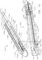
- FIG. 1is a perspective view of a surgical system including a handle assembly coupled to an interchangeable surgical tool assembly that is configured to be used in connection with conventional surgical staple/fastener cartridges and radio frequency (RF) cartridges according to one aspect of this disclosure.
- RFradio frequency
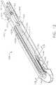
- FIG. 2is an exploded perspective assembly view of the surgical system of FIG. 1 according to one aspect of this disclosure.
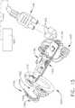
- FIG. 3is another exploded perspective assembly view of portions of the handle assembly and interchangeable surgical tool assembly of FIGS. 1 and 2 according to one aspect of this disclosure.
- FIG. 4is an exploded assembly view of a proximal portion of the interchangeable surgical tool assembly of FIGS. 1-3 according to one aspect of this disclosure.
- FIG. 5is another exploded assembly view of a distal portion of the interchangeable surgical tool assembly of FIGS. 1-5 according to one aspect of this disclosure.
- FIG. 6is a partial cross-sectional view of the end effector depicted in FIGS. 1-5 supporting an RF cartridge therein and with tissue clamped between the cartridge and the anvil according to one aspect of this disclosure.
- FIG. 7is a partial cross-sectional view of the anvil of FIG. 6 according to one aspect of this disclosure.
- FIG. 8is another exploded assembly view of a portion of the interchangeable surgical tool assembly of FIGS. 1-5 according to one aspect of this disclosure.
- FIG. 9is another exploded assembly view of the interchangeable surgical tool assembly and handle assembly of FIGS. 1 and 2 according to one aspect of this disclosure.
- FIG. 10is a perspective view of an RF cartridge and an elongate channel of the interchangeable surgical tool assembly of FIGS. 1-5 according to one aspect of this disclosure.
- FIG. 11is a partial perspective view of portions of the RF cartridge and elongate channel of FIG. 10 with a knife member according to one aspect of this disclosure.
- FIG. 12is another perspective view of the RF cartridge installed in the elongate channel of FIG. 10 and illustrating a portion of a flexible shaft circuit arrangement according to one aspect of this disclosure.
- FIG. 13is a cross-sectional end view of the RF cartridge and elongate channel of FIG. 12 taken along lines 13 - 13 in FIG. 12 according to one aspect of this disclosure.
- FIG. 14is a top cross-sectional view of a portion of the interchangeable surgical tool assembly of FIGS. 1 and 5 with the end effector thereof in an articulated position according to one aspect of this disclosure.
- FIG. 15is a perspective view of an onboard circuit board arrangement and RF generator plus configuration according to one aspect of this disclosure.
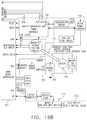
- FIGS. 16A-16Bis a block diagram of a control circuit of the surgical instrument of FIG. 1 spanning two drawing sheets according to one aspect of this disclosure.
- FIG. 17is a block diagram of the control circuit of the surgical instrument of FIG. 1 illustrating interfaces between the handle assembly, the power assembly, and the handle assembly and the interchangeable shaft assembly according to one aspect of this disclosure.
- FIG. 18is a schematic diagram of a surgical instrument configured to control various functions according to one aspect of this disclosure.
- FIG. 19is a schematic cross-sectional view of an electrosurgical end effector according to one aspect of this disclosure.
- FIG. 20is a perspective view of an end effector according to one aspect of this disclosure.
- Electrosurgical devicesmay be used in many surgical operations. Electrosurgical devices may apply electrical energy to tissue in order to treat tissue.
- An electrosurgical devicemay comprise an instrument having a distally mounted end effector comprising one or more electrodes. The end effector can be positioned against tissue such that electrical current may be introduced into the tissue.
- Electrosurgical devicescan be configured for monopolar or bipolar operation. During monopolar operation, current may be introduced into the tissue by an active (or source) electrode on the end effector and returned through a return electrode. The return electrode may be a grounding pad and separately located on a patient's body. During bipolar operation, current may be introduced into and returned from the tissue by the active and return electrodes, respectively, of the end effector.
- the end effectormay include two or more jaw members. At least one of the jaw members may have at least one electrode. At least one jaw may be moveable from a position spaced apart from the opposing jaw for receiving tissues to a position in which the space between the jaw members is less than that of the first position. This movement of the moveable jaw may compress the tissue held between. Heat generated by the current flow through the tissue in combination with the compression achieved by the jaw's movement may form hemostatic seals within the tissue and/or between tissues and, thus, may be particularly useful for sealing blood vessels, for example.
- the end effectormay comprise a cutting member. The cutting member may be movable relative to the tissue and the electrodes to transect the tissue.
- Electrosurgical devicesalso may include mechanisms to clamp tissue together, such as a stapling device, and/or mechanisms to sever tissue, such as a tissue knife.
- An electrosurgical devicemay include a shaft for placing the end effector proximate to tissue undergoing treatment.
- the shaftmay be straight or curved, bendable or non-bendable.
- the shaftmay have one or more articulation joints to permit controlled bending of the shaft. Such joints may permit a user of the electrosurgical device to place the end effector in contact with tissue at an angle to the shaft when the tissue being treated is not readily accessible using an electrosurgical device having a straight, non-bending shaft.
- RF energyis a form of electrical energy that may be in the frequency range of 200 kilohertz (kHz) to 1 megahertz (MHz).
- kHzkilohertz
- MHzmegahertz
- an electrosurgical instrumentcan transmit low frequency RF energy through tissue, which causes ionic agitation, or friction, in effect resistive heating, thereby increasing the temperature of the tissue. Because a sharp boundary is created between the affected tissue and the surrounding tissue, surgeons can operate with a high level of precision and control, without sacrificing un-targeted adjacent tissue. The low operating temperatures of RF energy is useful for removing, shrinking, or sculpting soft tissue while simultaneously sealing blood vessels. RF energy works particularly well on connective tissue, which is primarily comprised of collagen and shrinks when contacted by heat.
- the RF energymay be in a frequency range described in EN 60601-2-2:2009+A11:2011, Definition 201.3.218—HIGH FREQUENCY.
- the frequency in monopolar RF applicationsmay be typically restricted to less than 5 MHz.
- the frequency in bipolar RF applicationscan be almost anything. Frequencies above 200 kHz can be typically used for monopolar applications in order to avoid the unwanted stimulation of nerves and muscles that would result from the use of low frequency current. Lower frequencies may be used for bipolar applications if the risk analysis shows the possibility of neuromuscular stimulation has been mitigated to an acceptable level. Normally, frequencies above 5 MHz are not used in order to minimize the problems associated with high frequency leakage currents. Higher frequencies may, however, be used in the case of bipolar applications. It is generally recognized that 10 mA is the lower threshold of thermal effects on tissue.
- FIGS. 1 and 2depict a motor-driven surgical system 10 that may be used to perform a variety of different surgical procedures.
- the surgical system 10comprises an interchangeable surgical tool assembly 1000 that is operably coupled to a handle assembly 500 .
- the interchangeable surgical tool assembly 1000may also be effectively employed with a tool drive assembly of a robotically controlled or automated surgical system.
- the surgical tool assembly 1000 disclosed hereinmay be employed with various robotic systems, instruments, components and methods such as, but not limited to, those disclosed in U.S. Pat. No. 9,072,535, entitled SURGICAL STAPLING INSTRUMENTS WITH ROTATABLE STAPLE DEPLOYMENT ARRANGEMENTS, which is hereby incorporated by reference herein in its entirety.
- the handle assembly 500may comprise a handle housing 502 that includes a pistol grip portion 504 that can be gripped and manipulated by the clinician.
- the handle assembly 500operably supports a plurality of drive systems that are configured to generate and apply various control motions to corresponding portions of the interchangeable surgical tool assembly 1000 .
- the handle assembly 500may further include a handle frame 506 that operably supports the plurality of drive systems.
- the handle frame 506can operably support a “first” or closure drive system, generally designated as 510 , which may be employed to apply closing and opening motions to the interchangeable surgical tool assembly 1000 .
- the closure drive system 510may include an actuator in the form of a closure trigger 512 that is pivotally supported by the handle frame 506 .
- an actuatorin the form of a closure trigger 512 that is pivotally supported by the handle frame 506 .
- Such arrangementenables the closure trigger 512 to be manipulated by a clinician such that when the clinician grips the pistol grip portion 504 of the handle assembly 500 , the closure trigger 512 may be easily pivoted from a starting or “unactuated” position to an “actuated” position and more particularly to a fully compressed or fully actuated position.
- the cliniciandepresses the closure trigger 512 towards the pistol grip portion 504 .
- closure drive system 510when the clinician fully depresses the closure trigger 512 to attain the full closure stroke, the closure drive system 510 is configured to lock the closure trigger 512 into the fully depressed or fully actuated position.
- the clinicianWhen the clinician desires to unlock the closure trigger 512 to permit it to be biased to the unactuated position, the clinician simply activates a closure release button assembly 518 which enables the closure trigger to return to unactuated position.
- the closure release button assembly 518may also be configured to interact with various sensors that communicate with a microcontroller in the handle assembly 500 for tracking the position of the closure trigger 512 . Further details concerning the configuration and operation of the closure release button assembly 518 may be found in U.S. Patent Application Publication No. 2015/0272575.
- the handle assembly 500 and the handle frame 506may operably support another drive system referred to herein as a firing drive system 530 that is configured to apply firing motions to corresponding portions of the interchangeable surgical tool assembly that is attached thereto.
- the firing drive system 530may employ an electric motor 505 that is located in the pistol grip portion 504 of the handle assembly 500 .
- the motor 505may be a DC brushed driving motor having a maximum rotation of, approximately, 25,000 RPM, for example.
- the motor 505may include a brushless motor, a cordless motor, a synchronous motor, a stepper motor, or any other suitable electric motor.
- the motor 505may be powered by a power source 522 that in one form may comprise a removable power pack.
- the power packmay support a plurality of Lithium Ion (“LI”) or other suitable batteries therein.
- LILithium Ion
- a number of batteries that may be connected in seriesmay be used as the power source 522 for the surgical system 10 .
- the power source 522may be replaceable and/or rechargeable.
- the electric motor 505is configured to axially drive a longitudinally movable drive member 540 ( FIG. 3 ) in a distal and proximal directions depending upon the polarity of the motor. For example, when the motor 505 is driven in one rotary direction, the longitudinally movable drive member 540 will be axially driven in a distal direction “DD”. When the motor 505 is driven in the opposite rotary direction, the longitudinally movable drive member 540 will be axially driven in a proximal direction “PD”.
- the handle assembly 500can include a switch 513 which can be configured to reverse the polarity applied to the electric motor 505 by the power source 522 or otherwise control the motor 505 .
- the handle assembly 500can also include a sensor or sensors (not shown) that is configured to detect the position of the drive member and/or the direction in which the drive member is being moved. Actuation of the motor 505 can be controlled by a firing trigger (not shown) that is adjacent to the closure trigger 512 and pivotally supported on the handle assembly 500 .
- the firing triggermay be pivoted between an unactuated position and an actuated position.
- the firing triggermay be biased into the unactuated position by a spring or other biasing arrangement such that when the clinician releases the firing trigger, it may be pivoted or otherwise returned to the unactuated position by the spring or biasing arrangement.
- the firing triggercan be positioned “outboard” of the closure trigger 512 . As discussed in U.S. Patent Application Publication No.
- the handle assembly 500may be equipped with a firing trigger safety button (not shown) to prevent inadvertent actuation of the firing trigger.
- a firing trigger safety button(not shown) to prevent inadvertent actuation of the firing trigger.
- the safety buttonis contained in the handle assembly 500 where the clinician cannot readily access it and move it between a safety position preventing actuation of the firing trigger and a firing position wherein the firing trigger may be fired.
- the safety button and the firing triggerpivot down wherein they can then be manipulated by the clinician.
- the longitudinally movable drive member 540may have a rack of teeth 542 formed thereon for meshing engagement with a corresponding drive gear arrangement (not shown) that interfaces with the motor. See FIG. 3 . Further details regarding those features may be found in U.S. Patent Application Publication No. 2015/0272575. In at least one arrangement, however, the longitudinally movable drive member 540 is insulated to protect it from inadvertent RF energy. At least one form also includes a manually-actuatable “bailout” assembly that is configured to enable the clinician to manually retract the longitudinally movable drive member 540 should the motor 505 become disabled.
- the bailout assemblymay include a lever or bailout handle assembly that is stored within the handle assembly 500 under a releasable door 550 . See FIG. 2 .
- the levermay be configured to be manually pivoted into ratcheting engagement with the teeth in the drive member.
- the cliniciancan manually retract the drive member 540 by using the bailout handle assembly to ratchet the drive member in the proximal direction “PD”.
- the interchangeable surgical tool assembly 1000includes a surgical end effector 1500 that comprises a first jaw 1600 and a second jaw 1800 .
- the first jaw 1600comprises an elongate channel 1602 that is configured to operably support a conventional (mechanical) surgical staple/fastener cartridge 1400 ( FIG. 4 ) or a radio frequency (RF) cartridge 1700 ( FIGS. 1 and 2 ) therein.
- the second jaw 1800comprises an anvil 1810 that is pivotally supported relative to the elongate channel 1602 .
- the anvil 1810may be selectively moved toward and away from a surgical cartridge supported in the elongate channel 1602 between open and closed positions by actuating the closure drive system 510 .
- the anvil 1810is pivotally supported on a proximal end portion of the elongate channel 1602 for selective pivotal travel about a pivot axis that is transverse to the shaft axis SA.
- Actuation of the closure drive system 510may result in the distal axial movement of a proximal closure member or proximal closure tube 1910 that is attached to an articulation connector 1920 .
- the articulation connector 1920includes upper and lower tangs 1922 , 1924 that protrude distally from a distal end of the articulation connector 1920 to be movably coupled to an end effector closure sleeve or distal closure tube segment 1930 .
- the distal closure tube segment 1930includes an upper tang 1932 and a lower tang (not shown) that protrude proximally from a proximal end thereof.
- An upper double pivot link 1940includes proximal and distal pins 1941 , 1942 that engage corresponding holes in the upper tangs 1922 , 1932 of the articulation connector 1920 and distal closure tube segment 1930 , respectively.
- a lower double pivot link 1944includes proximal and distal pins 1945 , 1946 that engage corresponding holes in the lower tangs 1924 of the articulation connector 1920 and distal closure tube segment 1930 , respectively.
- the distal closure tube segment 1930includes positive jaw opening features or tabs 1936 , 1938 that correspond with corresponding portions of the anvil 1810 to apply opening motions to the anvil 1810 as the distal closure tube segment 1930 is retracted in the proximal direction PD to a starting position.
- positive jaw opening features or tabs 1936 , 1938that correspond with corresponding portions of the anvil 1810 to apply opening motions to the anvil 1810 as the distal closure tube segment 1930 is retracted in the proximal direction PD to a starting position.
- the interchangeable surgical tool assembly 1000includes a tool frame assembly 1200 that comprises a tool chassis 1210 that operably supports a nozzle assembly 1240 thereon.
- a tool frame assembly 1200that comprises a tool chassis 1210 that operably supports a nozzle assembly 1240 thereon.
- the tool chassis 1210 and nozzle arrangement 1240facilitate rotation of the surgical end effector 1500 about a shaft axis SA relative to the tool chassis 1210 . Such rotational travel is represented by arrow R in FIG. 1 .
- the interchangeable surgical tool assembly 1000includes a spine assembly 1250 that operably supports the proximal closure tube 1910 and is coupled to the surgical end effector 1500 .
- the spine assembly 1250may be fabricated from an upper spine segment 1251 and a lower spine segment 1252 that are interconnected together by snap features, adhesive, welding, etc.
- the spine assembly 1250includes a proximal end 1253 that is rotatably supported in the tool chassis 1210 .
- the proximal end 1253 of the spine assembly 1250is attached to a spine bearing (not shown) that is configured to be supported within the tool chassis 1210 .
- Such arrangementfacilitates rotatable attachment of the spine assembly 1250 to the tool chassis such that the spine assembly 1250 may be selectively rotated about a shaft axis SA relative to the tool chassis 1210 .
- the upper spine segment 1251terminates in an upper lug mount feature 1260 and the lower spine segment 1252 terminates in a lower lug mount feature 1270 .
- the upper lug mount feature 1260is formed with a lug slot 1262 therein that is adapted to mountingly support an upper mounting link 1264 therein.
- the lower lug mount feature 1270is formed with a lug slot 1272 therein that is adapted to mountingly support a lower mounting link 1274 therein.
- the upper mounting link 1264includes a pivot socket 1266 therein that is offset from the shaft axis SA.
- the pivot socket 1266is adapted to rotatably receive therein a pivot pin 1634 that is formed on a channel cap or anvil retainer 1630 that is attached to a proximal end portion 1610 of the elongate channel 1602 .
- the lower mounting link 1274includes lower pivot pin 1276 that adapted to be received within a pivot hole 1611 formed in the proximal end portion 1610 of the elongate channel 1602 .
- the lower pivot pin 1276 as well as the pivot hole 1611is offset from the shaft axis SA.
- the lower pivot pin 1276is vertically aligned with the pivot socket 1266 to define the articulation axis AA about which the surgical end effector 1500 may articulate relative to the shaft axis SA. See FIG. 1 .
- the articulation axis AAis transverse to the shaft axis SA, in at least one arrangement, the articulation axis AA is laterally offset therefrom and does not intersect the shaft axis SA.
- a proximal end 1912 of the proximal closure tube 1910is rotatably coupled to a closure shuttle 1914 by a connector 1916 that is seated in an annular groove 1915 in the proximal closure tube segment 1910 .
- the closure shuttle 1914is supported for axial travel within the tool chassis 1210 and has a pair of hooks 1917 thereon configured to engage the closure drive system 510 when the tool chassis 1210 is coupled to the handle frame 506 .
- the tool chassis 1210further supports a latch assembly 1280 for releasably latching the tool chassis 1210 to the handle frame 506 . Further details regarding the tool chassis 1210 and latch assembly 1280 may be found in U.S.
- the firing drive system 530 in the handle assembly 500is configured to be operably coupled to a firing system 1300 that is operably supported in the interchangeable surgical tool assembly 1000 .
- the firing system 1300may include an intermediate firing shaft portion 1310 that is configured to be axially moved in the distal and proximal directions in response to corresponding firing motions applied thereto by the firing drive system 530 . See FIG. 4 .
- a proximal end 1312 of the intermediate firing shaft portion 1310has a firing shaft attachment lug 1314 formed thereon that is configured to be seated into an attachment cradle 544 ( FIG. 3 ) that is on the distal end of the longitudinally movable drive member 540 of the firing drive system 530 within the handle assembly 500 .
- the intermediate firing shaft portion 1310is configured for attachment to a distal cutting portion or knife bar 1320 .
- the knife bar 1320is connected to a firing member or knife member 1330 .
- the knife member 1330comprises a knife body 1332 that operably supports a tissue cutting blade 1334 thereon.
- the knife body 1332may further include anvil engagement tabs or features 1336 and channel engagement features or a foot 1338 ( FIG. 8 ).
- the anvil engagement features 1336may serve to apply additional closure motions to the anvil 1810 as the knife member 1330 is advanced distally through the end effector 1500 .
- the surgical end effector 1500is selectively articulatable about the articulation axis AA by an articulation system 1360 .
- the articulation system 1360includes proximal articulation driver 1370 that is pivotally coupled to an articulation link 1380 .
- an offset attachment lug 1373is formed on a distal end 1372 of the proximal articulation driver 1370 .
- a pivot hole 1374is formed in the offset attachment lug 1373 and is configured to pivotally receive therein a proximal link pin 1382 formed on the proximal end 1381 of the articulation link 1380 .
- a distal end 1383 of the articulation link 1380includes a pivot hole 1384 that is configured to pivotally receive therein a channel pin 1618 formed on the proximal end portion 1610 of the elongate channel 1602 .
- proximal articulation driver 1370will thereby apply articulation motions to the elongate channel 1602 to thereby cause the surgical end effector 1500 to articulate about the articulation axis AA relative to the spine assembly 1250 .
- the proximal articulation driver 1370can be held in position by an articulation lock 1390 when the proximal articulation driver 1370 is not being moved in the proximal or distal directions.
- the interchangeable surgical tool assembly 1000can include a shifter assembly 1100 which can be configured to selectively and releasably couple the proximal articulation driver 1310 to the firing system 1300 .
- the shifter assembly 1100includes a lock collar, or lock sleeve 1110 , positioned around the intermediate firing shaft portion 1310 of the firing system 1300 wherein the lock sleeve 1110 can be rotated between an engaged position in which the lock sleeve 1110 operably couples the proximal articulation driver 1370 to the firing member assembly 1300 and a disengaged position in which the proximal articulation driver 1370 is not operably coupled to the firing member assembly 1300 .
- proximal articulation driver 1370When lock sleeve 1110 is in its engaged position, distal movement of the firing member assembly 1300 can move the proximal articulation driver 1370 distally and, correspondingly, proximal movement of the firing member assembly 1300 can move the proximal articulation driver 1370 proximally.
- lock sleeve 1110When lock sleeve 1110 is in its disengaged position, movement of the firing member assembly 1300 is not transmitted to the proximal articulation driver 1370 and, as a result, the firing member assembly 1300 can move independently of the proximal articulation driver 1370 .
- the proximal articulation driver 1370can be held in position by the articulation lock 1390 when the proximal articulation driver 1370 is not being moved in the proximal or distal directions by the firing member assembly 1300 .
- the intermediate firing shaft portion 1310 of the firing member assembly 1300is formed with two opposed flat sides with a drive notch 1316 formed therein. See FIG. 5 .
- the lock sleeve 1110comprises a cylindrical, or an at least substantially cylindrical, body that includes a longitudinal aperture that is configured to receive the intermediate firing shaft portion 1310 therethrough.
- the lock sleeve 1110can comprise diametrically-opposed, inwardly-facing lock protrusions that, when the lock sleeve 1110 is in one position, are engagingly received within corresponding portions of the drive notch 1316 in the intermediate firing shaft portion 1310 and, when in another position, are not received within the drive notch 1316 to thereby permit relative axial motion between the lock sleeve 1110 and the intermediate firing shaft 1310 .
- the lock sleeve 1110further includes a lock member 1112 that is sized to be movably received within a notch 1375 in a proximal end of the proximal articulation driver 1370 .
- Such arrangementpermits the lock sleeve 1110 to slightly rotate into and out of engagement with the intermediate firing shaft portion 1310 while remaining in position for engagement or in engagement with the notch 1375 in the proximal articulation driver 1370 .
- the lock protrusionsare positioned within the drive notch 1316 in the intermediate firing shaft portion 1310 such that a distal pushing force and/or a proximal pulling force can be transmitted from the firing member assembly 1300 to the lock sleeve 1110 .
- Such axial pushing or pulling motionis then transmitted from the lock sleeve 1110 to the proximal articulation driver 1370 to thereby articulate the surgical end effector 1500 .
- the firing member assembly 1300 , the lock sleeve 1110 , and the proximal articulation driver 1370will move together when the lock sleeve 1110 is in its engaged (articulation) position.
- the lock sleeve 1110is in its disengaged position, the lock protrusions are not received within the drive notch 1316 in the intermediate firing shaft portion 1310 and, as a result, a distal pushing force and/or a proximal pulling force may not be transmitted from the firing member assembly 1300 to the lock sleeve 1110 (and the proximal articulation driver 1370 ).
- the shifter assembly 1100further includes a shifter key 1120 that is configured to be slidably received within a key groove formed in the outer perimeter of the lock sleeve 1110 .
- a shifter key 1120is configured to be slidably received within a key groove formed in the outer perimeter of the lock sleeve 1110 .
- Such arrangementenables the shifter key 1120 to move axially with respect to the lock sleeve 1110 .
- U.S. patent application Ser. No. 15/635,631 entitled SURGICAL INSTRUMENT WITH AXIALLY MOVABLE CLOSURE MEMBERfiled on Jun.
- a portion of the shifter key 1120is configured to cammingly interact with a cam opening (not shown) in the proximal closure tube portion 1910 .
- the shifter assembly 1100further includes a switch drum 1130 that is rotatably received on a proximal end portion of the proximal closure tube portion 1910 .
- a portion of the shifter key 1120extends through an axial slot segment in the switch drum 1130 and is movably received within an arcuate slot segment in the switch drum 1130 .
- a switch drum torsion spring 1132is mounted on the switch drum 1130 and engages a portion of the nozzle assembly 1240 to apply a torsional bias or rotation which serves to rotate the switch drum 1130 until the portion of the shifter key 1120 reaches an end portion of the cam opening in the proximal closure tube portion 1910 .
- the switch drum 1130may provide a torsional bias to the shifter key 1120 which thereby causes the lock sleeve 1110 to rotate into its engaged position with the intermediate firing shaft portion 1310 .
- This positionalso corresponds to the unactuated configuration of the proximal closure tube 1910 (and distal closure tube segment 1930 ).
- actuation of the intermediate firing shaft portion 1310will result in the axial movement of the proximal articulation driver 1370 to facilitate articulation of the end effector 1500 .
- the usermay then actuate the proximal closure tube portion 1910 . Actuation of the proximal closure tube portion 1910 will result in the distal travel of the distal closure tube segment 1930 to ultimately apply a closing motion to the anvil 1810 .
- This distal travel of the proximal closure tube portion 1910will result in the cam opening therein cammingly interacting with a cam portion of the shifter key 1120 to thereby cause the shifter key 1120 to rotate the lock sleeve 1110 in an actuation direction.
- Such rotation of the lock sleeve 1110will result in the disengagement of the lock protrusions from the drive notch 1316 in the intermediate firing shaft portion 1310 .
- the firing drive system 530may be actuated to actuate the intermediate firing shaft portion 1310 without actuating the proximal articulation driver 1370 .
- the interchangeable surgical tool assembly 1000can comprise a slip ring assembly 1150 which can be configured to conduct electrical power to and/or from the surgical end effector 1500 and/or communicate signals to and/or from the surgical end effector 1500 , back to an onboard circuit board 1152 , while facilitating rotational travel of the shaft and end effector 1500 about the shaft axis SA relative to the tool chassis 1210 by rotating the nozzle assembly 1240 .
- the onboard circuit board 1152includes an onboard connector 1154 that is configured to interface with a housing connector 562 ( FIG. 9 ) communicating with a microprocessor 560 that is supported in the handle assembly 500 or robotic system controller, for example.
- the slip ring assembly 1150is configured to interface with a proximal connector 1153 that interfaces with the onboard circuit board 1152 . Further details concerning the slip ring assembly 1150 and associated connectors may be found in U.S. patent application Ser. No. 13/803,086, now U.S. Patent Application Publication No. 2014/0263541, and U.S. patent application Ser. No. 15/019,196 which have each been herein incorporated by reference in their respective entirety as well as in U.S. patent application Ser. No. 13/800,067, entitled STAPLE CARTRIDGE TISSUE THICKNESS SENSOR SYSTEM, now U.S. Patent Application Publication No. 2014/0263552, which is hereby incorporated by reference herein in its entirety.
- FIG. 4An example version of the interchangeable surgical tool assembly 1000 disclosed herein may be employed in connection with a standard (mechanical) surgical fastener cartridge 1400 or a cartridge 1700 that is configured to facilitate cutting of tissue with the knife member and seal the cut tissue using radio frequency (RF) energy.
- RFradio frequency
- FIG. 4a conventional or standard mechanical-type cartridge 1400 is depicted.
- Such cartridge arrangementsare known and may comprise a cartridge body 1402 that is sized and shaped to be removably received and supported in the elongate channel 1602 .
- the cartridge body 1402may be configured to be removably retained in snap engagement with the elongate channel 1602 .
- the cartridge body 1402includes an elongate slot 1404 to accommodate axial travel of the knife member 1330 therethrough.
- the cartridge body 1402operably supports therein a plurality of staple drivers (not shown) that are aligned in rows on each side of the centrally disposed elongate slot 1404 .
- the driversare associated with corresponding staple/fastener pockets 1412 that open through the upper deck surface 1410 of the cartridge body 1402 .
- Each of the staple driverssupports one or more surgical staple or fastener (not shown) thereon.
- a sled assembly 1420is supported within a proximal end of the cartridge body 1402 and is located proximal to the drivers and fasteners in a starting position when the cartridge 1400 is new and unfired.
- the sled assembly 1420includes a plurality of sloped or wedge-shaped cams 1422 wherein each cam 1422 corresponds to a particular line of fasteners or drivers located on a side of the slot 1404 .
- the sled assembly 1420is configured to be contacted and driven by the knife member 1330 as the knife member is driven distally through the tissue that is clamped between the anvil and the cartridge deck surface 1410 .
- the fastener(s) supported thereonare driven out of their staple pockets 1412 and through the tissue that is clamped between anvil and the cartridge.
- the anvil 1810 in at least one formincludes an anvil mounting portion 1820 that has a pair of anvil trunnions 1822 protruding laterally therefrom to be pivotally received in corresponding trunnion cradles 1614 formed in the upstanding walls 1622 of the proximal end portion 1610 of the elongate channel 1602 .
- the anvil trunnions 1822are pivotally retained in their corresponding trunnion cradle 1614 by the channel cap or anvil retainer 1630 .
- the anvil mounting portion 1820is movably or pivotably supported on the elongate channel 1602 for selective pivotal travel relative thereto about a fixed anvil pivot axis that is transverse to the shaft axis SA.
- the anvil 1810includes an anvil body portion 1812 that is fabricated from an electrically conductive metal material for example and has a staple forming undersurface 1813 that has a series of fastener forming pockets 1814 formed therein on each side of a centrally disposed anvil slot 1815 that is configured to slidably accommodate the knife member 1330 therein.
- the anvil slot 1815opens into an upper opening 1816 that extends longitudinally through the anvil body 1812 to accommodate the anvil engagement features 1336 on the knife member 1330 during firing.
- a conventional mechanical surgical staple/fastener cartridge 1400is installed in the elongate channel 1602 , the staples/fasteners are driven through the tissue T and into forming contact with the corresponding fastener forming pockets 1814 .
- the anvil body 1812may have an opening in the upper portion thereof to facilitate ease of installation for example.
- An anvil cap 1818may be inserted therein and welded to the anvil body 1812 to enclose the opening and improve the overall stiffness of the anvil body 1812 .
- the tissue facing segments 1817 of the fastener forming undersurface 1813may have electrically insulative material 1819 thereon.
- the interchangeable surgical tool assembly 1000is configured with a firing member lockout system, generally designated as 1640 . See FIG. 8 .
- the elongate channel 1602includes a bottom surface or bottom portion 1620 that has two upstanding side walls 1622 protruding therefrom.
- a centrally disposed longitudinal channel slot 1624is formed through the bottom portion 1620 to facilitate the axial travel of the knife member 1330 therethrough.
- the channel slot 1624opens into a longitudinal passage 1626 that accommodates the channel engagement feature or foot 1338 on the knife member 1330 .
- the passage 1626serves to define two inwardly extending ledge portions 1628 that serve to engage corresponding portions of the channel engagement feature or foot 1338 .
- the firing member lockout system 1640includes proximal openings 1642 located on each side of the channel slot 1624 that are each configured to receive corresponding portions of the channel engagement feature or foot 1338 when the knife member 1330 is in a starting position.
- a knife lockout spring 1650is supported in the proximal end 1610 of the elongate channel 1602 and serves to bias the knife member 1330 downward.
- the knife lockout spring 1650includes two distally ending spring arms 1652 that are configured to engage corresponding central channel engagement features 1337 on the knife body 1332 .
- the spring arms 1652are configured to bias the central channel engagement features 1337 downward.
- the knife member 1330when in the starting (unfired position), the knife member 1330 is biased downward such that the channel engagement features or foot 1338 is received within the corresponding proximal openings 1642 in the elongate 1602 channel.
- the central channel engagement features 1137 and/or foot 1338When in that locked position, if one were to attempt to distally advance the knife 1330 , the central channel engagement features 1137 and/or foot 1338 would engage upstanding ledges 1654 on the elongate channel 1602 ( FIGS. 8 and 11 ) and the knife 1330 could not be fired.
- the firing member lockout system 1640also includes an unlocking assembly 1660 formed or supported on a distal end of the firing member body 1332 .
- the unlocking assembly 1660includes a distally extending ledge 1662 that is configured to engage an unlocking feature 1426 formed on the sled assembly 1420 when the sled assembly 1420 is in its starting position in an unfired surgical staple cartridge 1400 .
- the ledge 1662 on the unlocking assembly 1660contacts the unlocking feature 1426 on the sled assembly 1420 which serves to bias the knife member 1330 upward such that the central channel engagement features 1137 and/or foot 1338 clear the upstanding ledges 1654 in the channel bottom 1620 to facilitate axial passage of the knife member 1330 through the elongate channel 1602 . If a partially fired cartridge 1400 is unwittingly installed in the elongate channel, the sled assembly 1420 will not be in the starting position and the knife member 1330 will remain in the locked position.
- the clinicianmay position the tool chassis 1210 of the interchangeable surgical tool assembly 1000 above or adjacent to the distal end of the handle frame 506 such that tapered attachment portions 1212 formed on the tool chassis 1210 are aligned with dovetail slots 507 in the handle frame 506 .
- the clinicianmay then move the surgical tool assembly 1000 along an installation axis IA that is perpendicular to the shaft axis SA to seat the tapered attachment portions 1212 in “operable engagement” with the corresponding dovetail receiving slots 507 in the distal end of the handle frame 506 .
- the firing shaft attachment lug 1314 on the intermediate firing shaft portion 1310will also be seated in the cradle 544 in the longitudinally movable drive member 540 within the handle assembly 500 and the portions of a pin 516 on a closure link 514 will be seated in the corresponding hooks 1917 in the closure shuttle 1914 .
- the term “operable engagement” in the context of two componentsmeans that the two components are sufficiently engaged with each other so that upon application of an actuation motion thereto, the components may carry out their intended action, function and/or procedure.
- the onboard connector 1154 on the surgical tool assembly 1000is coupled to the housing connector 562 that communicates with the microprocessor 560 that is supported in the handle assembly 500 or robotic system controller, for example.
- the clinicianmay introduce the surgical end effector 1500 into the surgical site through a trocar or other opening in the patient to access the target tissue.
- the cliniciantypically axially aligns the surgical end effector 1500 along the shaft axis SA (unarticulated state).
- SAshaft axis
- the clinicianmay need to articulate the end effector 1500 to advantageously position it adjacent the target tissue. This is prior to closing the anvil 1810 onto the target tissue, so the closure drive system 510 would remain unactuated.
- actuation of the firing drive system 530will result in the application of articulation motions to the proximal articulation driver 1370 .
- the firing drive system 530is deactivated and the articulation lock 1390 may retain the surgical end effector 1500 in the articulated position.
- the clinicianmay then actuate the closure drive system 510 to close the anvil 1810 onto the target tissue.
- Such actuation of the closure drive system 510may also result in the shifter assembly 1100 delinking the proximal articulation driver 1370 from the intermediate firing shaft portion 1310 .
- the clinicianmay once again actuate the firing drive system 530 to axially advance the firing member 1330 through the surgical staple/fastener cartridge 1400 or RF cartridge 1700 to cut the clamped tissue and fire the staples/fasteners into the cut tissue T.
- Other closure and firing drive arrangements, actuator arrangementsmay also be employed to control the axial movement of the closure system components, the articulation system components and/or the firing system components of the surgical tool assembly 1000 without departing from the scope of the present disclosure.
- the surgical tool assembly 1000is configured to be used in connection with conventional mechanical surgical staple/fastener cartridges 1400 as well as with RF cartridges 1700 .
- the RF cartridge 1700may facilitate mechanical cutting of tissue that is clamped between the anvil 1810 and the RF cartridge 1700 with the knife member 1330 while coagulating electrical current is delivered to the tissue in the current path.
- Alternative arrangements for mechanically cutting and coagulating tissue using electrical currentare disclosed in, for example, U.S. Pat. Nos. 5,403,312; 7,780,663 and U.S. patent application Ser. No.
- the RF surgical cartridge 1700includes a cartridge body 1710 that is sized and shaped to be removably received and supported in the elongate channel 1602 .
- the cartridge body 1710may be configured to be removably retained in snap engagement with the elongate channel 1602 .
- the cartridge body 1710may be fabricated from a polymer material, such as, for example, an engineering thermoplastic such as the liquid crystal polymer (LCP) VECTRATM and the elongate channel 1602 may be fabricated from metal.
- LCPliquid crystal polymer
- the cartridge body 1710includes a centrally disposed elongate slot 1712 that extends longitudinally through the cartridge body to accommodate longitudinal travel of the knife 1330 therethrough.
- a pair of lockout engagement tails 1714extend proximally from the cartridge body 1710 .
- Each lockout engagement tail 1714has a lockout pad 1716 formed on the underside thereof that are sized to be received within a corresponding proximal opening portion 1642 in the channel bottom 1620 .
- the lockout engagement tails 1714cover the openings 1642 and ledges 1654 to retain the knife 1330 in an unlocked position ready for firing.
- the cartridge body 1710is formed with a centrally disposed raised electrode pad 1720 .
- the elongate slot 1712extends through the center of the electrode pad 1720 and serves to divide the pad 1720 into a left pad segment 1720 L and a right pad segment 1720 R.
- a right flexible circuit assembly 1730 Ris attached to the right pad segment 1720 R and a left flexible circuit assembly 1730 L is attached to the left pad segment 1720 L.
- the right flexible circuit 1730 Rcomprises a plurality of electrical conductors 1732 R that may include, for example, wider electrical conductors/conductors for RF purposes and thinner electrical conductors for conventional stapling purposes that are supported or attached or embedded into a right insulator sheath/member 1734 R that is attached to the right pad 1720 R.
- the right flexible circuit assembly 1730 Rincludes a “phase one”, proximal right electrode 1736 R and a “phase two” distal right electrode 1738 R.
- the left flexible circuit assembly 1730 Lcomprises a plurality of electrical conductors 1732 L that may include, for example, wider electrical conductors/conductors for RF purposes and thinner electrical conductors for conventional stapling purposes that are supported or attached or embedded into a left insulator sheath/member 1734 L that is attached to the left pad 1720 L.
- the left flexible circuit assembly 1730 Lincludes a “phase one”, proximal left electrode 1736 L and a “phase two” distal left electrode 1738 L.
- the left and right electrical conductors 1732 L, 1732 Rare attached to a distal micro-chip 1740 mounted to the distal end portion of the cartridge body 1710 .
- each of the right and left flexible circuits 1730 R, 1730 Lmay have an overall width “CW” of approximately 0.025 inches and each of the electrodes 1736 R, 1736 L, 1738 R, 1738 R has a width “EW” of approximately 0.010 inches for example. See FIG. 13 .
- CWoverall width
- EWwidth
- other widths/sizesare contemplated and may be employed in alternative aspects.
- RF energyis supplied to the surgical tool assembly 1000 by a conventional RF generator 400 through a supply lead 402 .
- the supply lead 402includes a male plug assembly 406 that is configured to be plugged into corresponding female connectors 410 that are attached to a segmented RF circuit 1160 on the an onboard circuit board 1152 . See FIG. 15 .
- Such arrangementfacilitates rotational travel of the shaft and end effector 1500 about the shaft axis SA relative to the tool chassis 1210 by rotating the nozzle assembly 1240 without winding up the supply lead 402 from the generator 400 .
- An onboard on/off power switch 420is supported on the latch assembly 1280 and tool chassis 1210 for turning the RF generator on and off.
- the onboard segmented RF circuit 1160communicates with the microprocessor 560 through the connectors 1154 and 562 .
- the handle assembly 500may also include a display screen 430 for viewing information about the progress of sealing, stapling, knife location, status of the cartridge, tissue, temperature, etc.
- the slip ring assembly 1150interfaces with a distal connector 1162 that includes a flexible shaft circuit strip or assembly 1164 that may include a plurality of narrow electrical conductors 1166 for stapling related activities and wider electrical conductors 1168 used for RF purposes. As shown in FIGS.
- the flexible shaft circuit strip 1164is centrally supported between the laminated plates or bars 1322 that form the knife bar 1320 .
- Such arrangementfacilitates sufficient flexing of the knife bar 1320 and flexible shaft circuit strip 1164 during articulation of the end effector 1500 while remaining sufficiently stiff so as to enable the knife member 1330 to be distally advanced through the clamped tissue.
- the elongate channel 1602includes a channel circuit 1670 supported in a recess 1621 that extends from the proximal end 1610 of the elongate channel 1602 to a distal location 1623 in the elongate channel bottom portion 1620 .
- the channel circuit 1670includes a proximal contact portion 1672 that contacts a distal contact portion 1169 of the flexible shaft circuit strip 1164 for electrical contact therewith.
- a distal end 1674 of the channel circuit 1670is received within a corresponding wall recess 1625 formed in one of the channel walls 1622 and is folded over and attached to an upper edge 1627 of the channel wall 1622 .
- a series of corresponding exposed contacts 1676are provided in the distal end 1674 of the channel circuit 1670 As shown in FIG. 10 .
- an end 1752 of a flexible cartridge circuit 1750is attached to the distal micro-chip 1740 and is affixed to the distal end portion of the cartridge body 1710 .
- Another end 1754is folded over the edge of the cartridge deck surface 1711 and includes exposed contacts 1756 configured to make electrical contact with the exposed contacts 1676 of the channel circuit 1670 .
- the electrodes as well as the distal micro-chip 1740are powered and communicate with the onboard circuit board 1152 through contact between the flexible cartridge circuit 1750 , the flexible channel circuit 1670 , the flexible shaft circuit 1164 and the slip ring assembly 1150 .
- FIGS. 16A-16Bis a block diagram of a control circuit 700 of the surgical instrument 10 of FIG. 1 spanning two drawing sheets according to one aspect of this disclosure.
- a handle assembly 702may include a motor 714 which can be controlled by a motor driver 715 and can be employed by the firing system of the surgical instrument 10 .
- the motor 714may be a DC brushed driving motor having a maximum rotational speed of approximately 25,000 RPM.
- the motor 714may include a brushless motor, a cordless motor, a synchronous motor, a stepper motor, or any other suitable electric motor.
- the motor driver 715may comprise an H-Bridge driver comprising field-effect transistors (FETs) 719 , for example.
- the motor 714can be powered by the power assembly 706 releasably mounted to the handle assembly 500 for supplying control power to the surgical instrument 10 .
- the power assembly 706may comprise a battery which may include a number of battery cells connected in series that can be used as the power source to power the surgical instrument 10 .
- the battery cells of the power assembly 706may be replaceable and/or rechargeable.
- the battery cellscan be Lithium-Ion batteries which can be separably couplable to the power assembly 706 .
- the shaft assembly 704may include a shaft assembly controller 722 which can communicate with a safety controller and power management controller 716 through an interface while the shaft assembly 704 and the power assembly 706 are coupled to the handle assembly 702 .
- the interfacemay comprise a first interface portion 725 which may include one or more electric connectors for coupling engagement with corresponding shaft assembly electric connectors and a second interface portion 727 which may include one or more electric connectors for coupling engagement with corresponding power assembly electric connectors to permit electrical communication between the shaft assembly controller 722 and the power management controller 716 while the shaft assembly 704 and the power assembly 706 are coupled to the handle assembly 702 .
- One or more communication signalscan be transmitted through the interface to communicate one or more of the power requirements of the attached interchangeable shaft assembly 704 to the power management controller 716 .
- the power management controllermay modulate the power output of the battery of the power assembly 706 , as described below in greater detail, in accordance with the power requirements of the attached shaft assembly 704 .
- the connectorsmay comprise switches which can be activated after mechanical coupling engagement of the handle assembly 702 to the shaft assembly 704 and/or to the power assembly 706 to allow electrical communication between the shaft assembly controller 722 and the power management controller 716 .
- the interfacecan facilitate transmission of the one or more communication signals between the power management controller 716 and the shaft assembly controller 722 by routing such communication signals through a main controller 717 residing in the handle assembly 702 , for example.
- the interfacecan facilitate a direct line of communication between the power management controller 716 and the shaft assembly controller 722 through the handle assembly 702 while the shaft assembly 704 and the power assembly 706 are coupled to the handle assembly 702 .
- the main controller 717may be any single core or multicore processor such as those known under the trade name ARM Cortex by Texas Instruments.
- the main controller 717may be an LM4F230H5QR ARM Cortex-M4F Processor Core, available from Texas Instruments, for example, comprising on-chip memory of 256 KB single-cycle flash memory, or other non-volatile memory, up to 40 MHz, a prefetch buffer to improve performance above 40 MHz, a 32 KB single-cycle serial random access memory (SRAM), internal read-only memory (ROM) loaded with StellarisWare® software, 2 KB electrically erasable programmable read-only memory (EEPROM), one or more pulse width modulation (PWM) modules, one or more quadrature encoder inputs (QEI) analog, one or more 12-bit Analog-to-Digital Converters (ADC) with 12 analog input channels, details of which are available for the product datasheet.
- the safety controllermay be a safety controller platform comprising two controller-based families such as TMS570 and RM4x known under the trade name Hercules ARM Cortex R4, also by Texas Instruments.
- the safety controllermay be configured specifically for IEC 61508 and ISO 26262 safety critical applications, among others, to provide advanced integrated safety features while delivering scalable performance, connectivity, and memory options.
- the power assembly 706may include a power management circuit which may comprise the power management controller 716 , a power modulator 738 , and a current sense circuit 736 .
- the power management circuitcan be configured to modulate power output of the battery based on the power requirements of the shaft assembly 704 while the shaft assembly 704 and the power assembly 706 are coupled to the handle assembly 702 .
- the power management controller 716can be programmed to control the power modulator 738 of the power output of the power assembly 706 and the current sense circuit 736 can be employed to monitor power output of the power assembly 706 to provide feedback to the power management controller 716 about the power output of the battery so that the power management controller 716 may adjust the power output of the power assembly 706 to maintain a desired output.
- the power management controller 716 and/or the shaft assembly controller 722each may comprise one or more processors and/or memory units which may store a number of software modules.
- the surgical instrument 10may comprise an output device 742 which may include devices for providing a sensory feedback to a user. Such devices may comprise, for example, visual feedback devices (e.g., an LCD display screen, LED indicators), audio feedback devices (e.g., a speaker, a buzzer) or tactile feedback devices (e.g., haptic actuators).
- the output device 742may comprise a display 743 which may be included in the handle assembly 702 .
- the shaft assembly controller 722 and/or the power management controller 716can provide feedback to a user of the surgical instrument 10 through the output device 742 .
- the interfacecan be configured to connect the shaft assembly controller 722 and/or the power management controller 716 to the output device 742 .
- the output device 742can instead be integrated with the power assembly 706 . In such circumstances, communication between the output device 742 and the shaft assembly controller 722 may be accomplished through the interface while the shaft assembly 704 is coupled to the handle assembly 702 .
- the control circuit 700comprises circuit segments configured to control operations of the powered surgical instrument 10 .
- a safety controller segment(Segment 1 ) comprises a safety controller and the main controller 717 segment (Segment 2 ).
- the safety controller and/or the main controller 717are configured to interact with one or more additional circuit segments such as an acceleration segment, a display segment, a shaft segment, an encoder segment, a motor segment, and a power segment.
- Each of the circuit segmentsmay be coupled to the safety controller and/or the main controller 717 .
- the main controller 717is also coupled to a flash memory.
- the main controller 717also comprises a serial communication interface.
- the main controller 717comprises a plurality of inputs coupled to, for example, one or more circuit segments, a battery, and/or a plurality of switches.
- the segmented circuitmay be implemented by any suitable circuit, such as, for example, a printed circuit board assembly (PCBA) within the powered surgical instrument 10 .
- PCBAprinted circuit board assembly
- processoras used herein includes any microprocessor, processors, controller, controllers, or other basic computing device that incorporates the functions of a computer's central processing unit (CPU) on an integrated circuit or at most a few integrated circuits.
- the main controller 717is a multipurpose, programmable device that accepts digital data as input, processes it according to instructions stored in its memory, and provides results as output. It is an example of sequential digital logic, as it has internal memory.
- the control circuit 700can be configured to implement one or more of the processes described herein.
- the acceleration segment(Segment 3 ) comprises an accelerometer.
- the accelerometeris configured to detect movement or acceleration of the powered surgical instrument 10 .
- Input from the accelerometermay be used to transition to and from a sleep mode, identify an orientation of the powered surgical instrument, and/or identify when the surgical instrument has been dropped.
- the acceleration segmentis coupled to the safety controller and/or the main controller 717 .
- the display segment(Segment 4 ) comprises a display connector coupled to the main controller 717 .
- the display connectorcouples the main controller 717 to a display through one or more integrated circuit drivers of the display.
- the integrated circuit drivers of the displaymay be integrated with the display and/or may be located separately from the display.
- the displaymay comprise any suitable display, such as, for example, an organic light-emitting diode (OLED) display, a liquid-crystal display (LCD), and/or any other suitable display.
- the display segmentis coupled to the safety controller.
- the shaft segment(Segment 5 ) comprises controls for an interchangeable shaft assembly 500 coupled to the surgical instrument 10 ( FIGS. 1-5 ) and/or one or more controls for an end effector 1500 coupled to the interchangeable shaft assembly 500 .
- the shaft segmentcomprises a shaft connector configured to couple the main controller 717 to a shaft PCBA.
- the shaft PCBAcomprises a low-power microcontroller with a ferroelectric random access memory (FRAM), an articulation switch, a shaft release Hall effect switch, and a shaft PCBA EEPROM.
- the shaft PCBA EEPROMcomprises one or more parameters, routines, and/or programs specific to the interchangeable shaft assembly 500 and/or the shaft PCBA.
- the shaft PCBAmay be coupled to the interchangeable shaft assembly 500 and/or integral with the surgical instrument 10 .
- the shaft segmentcomprises a second shaft EEPROM.
- the second shaft EEPROMcomprises a plurality of algorithms, routines, parameters, and/or other data corresponding to one or more shaft assemblies 500 and/or end effectors 1500 that may be interfaced with the powered surgical instrument 10 .
- the position encoder segment(Segment 6 ) comprises one or more magnetic angle rotary position encoders.
- the one or more magnetic angle rotary position encodersare configured to identify the rotational position of the motor 714 , an interchangeable shaft assembly 500 , and/or an end effector 1500 of the surgical instrument 10 ( FIGS. 1-5 ).
- the magnetic angle rotary position encodersmay be coupled to the safety controller and/or the main controller 717 .
- the motor circuit segment(Segment 7 ) comprises a motor 714 configured to control movements of the powered surgical instrument 10 ( FIGS. 1-5 ).
- the motor 714is coupled to the main microcontroller processor 717 by an H-bridge driver comprising one or more H-bridge field-effect transistors (FETs) and a motor controller.
- the H-bridge driveris also coupled to the safety controller.
- a motor current sensoris coupled in series with the motor to measure the current draw of the motor.
- the motor current sensoris in signal communication with the main controller 717 and/or the safety controller.
- the motor 714is coupled to a motor electromagnetic interference (EMI) filter.
- EMImotor electromagnetic interference
- the motor controllercontrols a first motor flag and a second motor flag to indicate the status and position of the motor 714 to the main controller 717 .
- the main controller 717provides a pulse-width modulation (PWM) high signal, a PWM low signal, a direction signal, a synchronize signal, and a motor reset signal to the motor controller through a buffer.
- PWMpulse-width modulation
- the power segmentis configured to provide a segment voltage to each of the circuit segments.
- the power segment(Segment 8 ) comprises a battery coupled to the safety controller, the main controller 717 , and additional circuit segments.
- the batteryis coupled to the segmented circuit by a battery connector and a current sensor.
- the current sensoris configured to measure the total current draw of the segmented circuit.
- one or more voltage convertersare configured to provide predetermined voltage values to one or more circuit segments.
- the segmented circuitmay comprise 3.3V voltage converters and/or 5V voltage converters.
- a boost converteris configured to provide a boost voltage up to a predetermined amount, such as, for example, up to 13V.
- the boost converteris configured to provide additional voltage and/or current during power intensive operations and prevent brownout or low-power conditions.
- a plurality of switchesare coupled to the safety controller and/or the main controller 717 .
- the switchesmay be configured to control operations of the surgical instrument 10 ( FIGS. 1-5 ), of the segmented circuit, and/or indicate a status of the surgical instrument 10 .
- a bail-out door switch and Hall effect switch for bailoutare configured to indicate the status of a bail-out door.
- a plurality of articulation switchessuch as, for example, a left side articulation left switch, a left side articulation right switch, a left side articulation center switch, a right side articulation left switch, a right side articulation right switch, and a right side articulation center switch are configured to control articulation of an interchangeable shaft assembly 500 ( FIGS.
- a left side reverse switch and a right side reverse switchare coupled to the main controller 717 .
- the left side switchescomprising the left side articulation left switch, the left side articulation right switch, the left side articulation center switch, and the left side reverse switch are coupled to the main controller 717 by a left flex connector.
- the right side switchescomprising the right side articulation left switch, the right side articulation right switch, the right side articulation center switch, and the right side reverse switch are coupled to the main controller 717 by a right flex connector.
- a firing switch, a clamp release switch, and a shaft engaged switchare coupled to the main controller 717 .
- any suitable mechanical, electromechanical, or solid state switchesmay be employed to implement the plurality of switches, in any combination.
- the switchesmay be limit switches operated by the motion of components associated with the surgical instrument 10 ( FIGS. 1-5 ) or the presence of an object.
- Such switchesmay be employed to control various functions associated with the surgical instrument 10 .
- a limit switchis an electromechanical device that consists of an actuator mechanically linked to a set of contacts. When an object comes into contact with the actuator, the device operates the contacts to make or break an electrical connection.
- Limit switchesare used in a variety of applications and environments because of their ruggedness, ease of installation, and reliability of operation. They can determine the presence or absence, passing, positioning, and end of travel of an object.
- the switchesmay be solid state switches that operate under the influence of a magnetic field such as Hall-effect devices, magneto-resistive (MR) devices, giant magneto-resistive (GMR) devices, magnetometers, among others.
- the switchesmay be solid state switches that operate under the influence of light, such as optical sensors, infrared sensors, ultraviolet sensors, among others.
- the switchesmay be solid state devices such as transistors (e.g., FET, Junction-FET, metal-oxide semiconductor-FET (MOSFET), bipolar, and the like).
- Other switchesmay include electrical conductorless switches, ultrasonic switches, accelerometers, inertial sensors, among others.
- FIG. 17is another block diagram of the control circuit 700 of the surgical instrument of FIG. 1 illustrating interfaces between the handle assembly 702 and the power assembly 706 and between the handle assembly 702 and the interchangeable shaft assembly 704 according to one aspect of this disclosure.
- the handle assembly 702may comprise a main controller 717 , a shaft assembly connector 726 and a power assembly connector 730 .
- the power assembly 706may include a power assembly connector 732 , a power management circuit 734 that may comprise the power management controller 716 , a power modulator 738 , and a current sense circuit 736 .
- the shaft assembly connectors 730 , 732form an interface 727 .
- the power management circuit 734can be configured to modulate power output of the battery 707 based on the power requirements of the interchangeable shaft assembly 704 while the interchangeable shaft assembly 704 and the power assembly 706 are coupled to the handle assembly 702 .
- the power management controller 716can be programmed to control the power modulator 738 of the power output of the power assembly 706 and the current sense circuit 736 can be employed to monitor power output of the power assembly 706 to provide feedback to the power management controller 716 about the power output of the battery 707 so that the power management controller 716 may adjust the power output of the power assembly 706 to maintain a desired output.
- the shaft assembly 704comprises a shaft processor 719 coupled to a non-volatile memory 721 and shaft assembly connector 728 to electrically couple the shaft assembly 704 to the handle assembly 702 .
- the shaft assembly connectors 726 , 728form interface 725 .
- the main controller 717 , the shaft processor 719 , and/or the power management controller 716can be configured to implement one or more of the processes described herein.
- the surgical instrument 10may comprise an output device 742 to a sensory feedback to a user.
- Such devicesmay comprise visual feedback devices (e.g., an LCD display screen, LED indicators), audio feedback devices (e.g., a speaker, a buzzer), or tactile feedback devices (e.g., haptic actuators).
- the output device 742may comprise a display 743 that may be included in the handle assembly 702 .
- the shaft assembly controller 722 and/or the power management controller 716can provide feedback to a user of the surgical instrument 10 through the output device 742 .
- the interface 727can be configured to connect the shaft assembly controller 722 and/or the power management controller 716 to the output device 742 .
- the output device 742can be integrated with the power assembly 706 . Communication between the output device 742 and the shaft assembly controller 722 may be accomplished through the interface 725 while the interchangeable shaft assembly 704 is coupled to the handle assembly 702 .
- a control circuit 700FIGS. 16A-16B and 6 for controlling the operation of the surgical instrument 10 ( FIGS. 1-5 )
- the disclosurenow turns to various configurations of the surgical instrument 10 ( FIGS. 1-5 ) and control circuit 700 .
- FIG. 18is a schematic diagram of a surgical instrument 600 configured to control various functions according to one aspect of this disclosure.
- the surgical instrument 600is programmed to control distal translation of a displacement member such as the I-beam 614 .
- the surgical instrument 600comprises an end effector 602 that may comprise an anvil 616 , an I-beam 614 , and a removable staple cartridge 618 which may be interchanged with an RF cartridge 609 (shown in dashed line).
- the end effector 602 , anvil 616 , I-beam 614 , staple cartridge 618 , and RF cartridge 609may be configured as described herein, for example, with respect to FIGS. 1-15 .
- FIG. 18For conciseness and clarity of disclosure, several aspects of the present disclosure may be described with reference to FIG. 18 . It will be appreciated that the components shown schematically in FIG. 18 such as the control circuit 610 , sensors 638 , position sensor 634 , end effector 602 , I-beam 614 , staple cartridge 618 , RF cartridge 609 , anvil 616 , are described in connection with FIGS. 1-17 of this disclosure.
- the components represented schematically in FIG. 18may be readily substituted with the physical and functional equivalent components described in connection with FIGS. 1-17 .
- the control circuit 610may be implemented as the control circuit 700 shown and described in connection with FIGS. 16-17 .
- the sensors 638may be implemented as a limit switch, electromechanical device, solid state switches, Hall-effect devices, magneto-resistive (MR) devices, giant magneto-resistive (GMR) devices, magnetometers, among others.
- the sensors 638may be solid state switches that operate under the influence of light, such as optical sensors, infrared sensors, ultraviolet sensors, among others.
- the switchesmay be solid state devices such as transistors (e.g., FET, Junction-FET, metal-oxide semiconductor-FET (MOSFET), bipolar, and the like).
- the sensors 638may include electrical conductorless switches, ultrasonic switches, accelerometers, inertial sensors, among others.
- the position sensor 634may be implemented as an absolute positioning system comprising a magnetic rotary absolute positioning system implemented as an AS5055EQFT single-chip magnetic rotary position sensor available from Austria Microsystems, AG. The position sensor 634 may interface with the control circuit 700 to provide an absolute positioning system.
- the positionmay include multiple Hall-effect elements located above a magnet and coupled to a CORDIC processor (for Coordinate Rotation Digital Computer), also known as the digit-by-digit method and Volder's algorithm, is provided to implement a simple and efficient algorithm to calculate hyperbolic and trigonometric functions that require only addition, subtraction, bitshift, and table lookup operations.
- a CORDIC processorfor Coordinate Rotation Digital Computer
- the end effector 602may be implemented as surgical end effector 1500 shown and described in connection with FIGS. 1, 2, and 4 .
- the I-beam 614may be implemented as the knife member 1330 comprising a knife body 1332 that operably supports a tissue cutting blade 1334 thereon and may further include anvil engagement tabs or features 1336 and channel engagement features or a foot 1338 as shown and described in connection with FIGS. 2-4, 8, 11 and 14 .
- the staple cartridge 618may be implemented as the standard (mechanical) surgical fastener cartridge 1400 shown and described in connection with FIG. 4 .
- the RF cartridge 609may be implemented as the radio frequency (RF) cartridge 1700 shown and described in connection with FIGS. 1, 2, 6, and 10-13 .
- the anvil 616may be implemented the anvil 1810 shown and described in connection with FIGS. 1, 2, 4, and 6 .
- the position, movement, displacement, and/or translation of a liner displacement member, such as the I-beam 614can be measured by an absolute positioning system, sensor arrangement, and position sensor represented as position sensor 634 . Because the I-beam 614 is coupled to the longitudinally movable drive member 540 , the position of the I-beam 614 can be determined by measuring the position of the longitudinally movable drive member 540 employing the position sensor 634 . Accordingly, in the following description, the position, displacement, and/or translation of the I-beam 614 can be achieved by the position sensor 634 as described herein.
- a control circuit 610such as the control circuit 700 described in FIGS.
- the control circuit 610may comprise one or more microcontrollers, microprocessors, or other suitable processors for executing instructions that cause the processor or processors to control the displacement member, e.g., the I-beam 614 , in the manner described.
- a timer/counter circuit 631provides an output signal, such as elapsed time or a digital count, to the control circuit 610 to correlate the position of the I-beam 614 as determined by the position sensor 634 with the output of the timer/counter circuit 631 such that the control circuit 610 can determine the position of the I-beam 614 at a specific time (t) relative to a starting position.
- the timer/counter circuit 631may be configured to measure elapsed time, count external evens, or time external events.
- the control circuit 610may generate a motor set point signal 622 .
- the motor set point signal 622may be provided to a motor controller 608 .
- the motor controller 608may comprise one or more circuits configured to provide a motor drive signal 624 to the motor 604 to drive the motor 604 as described herein.
- the motor 604may be a brushed DC electric motor, such as the motor 505 shown in FIG. 1 .
- the velocity of the motor 604may be proportional to the motor drive signal 624 .
- the motor 604may be a brushless direct current (DC) electric motor and the motor drive signal 624 may comprise a pulse-width-modulated (PWM) signal provided to one or more stator windings of the motor 604 .
- PWMpulse-width-modulated
- the motor controller 608may be omitted and the control circuit 610 may generate the motor drive signal 624 directly.
- the motor 604may receive power from an energy source 612 .
- the energy source 612may be or include a battery, a super capacitor, or any other suitable energy source 612 .
- the motor 604may be mechanically coupled to the I-beam 614 via a transmission 606 .
- the transmission 606may include one or more gears or other linkage components to couple the motor 604 to the I-beam 614 .
- a position sensor 634may sense a position of the I-beam 614 .
- the position sensor 634may be or include any type of sensor that is capable of generating position data that indicates a position of the I-beam 614 .
- the position sensor 634may include an encoder configured to provide a series of pulses to the control circuit 610 as the I-beam 614 translates distally and proximally.
- the control circuit 610may track the pulses to determine the position of the I-beam 614 .
- Other suitable position sensormay be used, including, for example, a proximity sensor.
- Other types of position sensorsmay provide other signals indicating motion of the I-beam 614 .
- the position sensor 634may be omitted. Where the motor 604 is a stepper motor, the control circuit 610 may track the position of the I-beam 614 by aggregating the number and direction of steps that the motor 604 has been instructed to execute.
- the position sensor 634may be located in the end effector 602 or at any other portion of the instrument.
- the control circuit 610may be in communication with one or more sensors 638 .
- the sensors 638may be positioned on the end effector 602 and adapted to operate with the surgical instrument 600 to measure the various derived parameters such as gap distance versus time, tissue compression versus time, and anvil strain versus time.
- the sensors 638may comprise a magnetic sensor, a magnetic field sensor, a strain gauge, a pressure sensor, a force sensor, an inductive sensor such as an eddy current sensor, a resistive sensor, a capacitive sensor, an optical sensor, and/or any other suitable sensor for measuring one or more parameters of the end effector 602 .
- the sensors 638may include one or more sensors.
- the one or more sensors 638may comprise a strain gauge, such as a micro-strain gauge, configured to measure the magnitude of the strain in the anvil 616 during a clamped condition.
- the strain gaugeprovides an electrical signal whose amplitude varies with the magnitude of the strain.
- the sensors 638may comprise a pressure sensor configured to detect a pressure generated by the presence of compressed tissue between the anvil 616 and the staple cartridge 618 .
- the sensors 638may be configured to detect impedance of a tissue section located between the anvil 616 and the staple cartridge 618 that is indicative of the thickness and/or fullness of tissue located therebetween.
- the sensors 638may be configured to measure forces exerted on the anvil 616 by the closure drive system.
- one or more sensors 638can be at an interaction point between the closure tube 1910 ( FIGS. 1-4 ) and the anvil 616 to detect the closure forces applied by the closure tube 1910 to the anvil 616 .
- the forces exerted on the anvil 616can be representative of the tissue compression experienced by the tissue section captured between the anvil 616 and the staple cartridge 618 .
- the one or more sensors 638can be positioned at various interaction points along the closure drive system to detect the closure forces applied to the anvil 616 by the closure drive system.
- the one or more sensors 638may be sampled in real time during a clamping operation by a processor as described in FIGS. 16A-16B .
- the control circuit 610receives real-time sample measurements to provide analyze time based information and assess, in real time, closure forces applied to the anvil 616 .
- a current sensor 636can be employed to measure the current drawn by the motor 604 .
- the force required to advance the I-beam 614corresponds to the current drawn by the motor 604 .
- the forceis converted to a digital signal and provided to the control circuit 610 .
- the RF energy source 400is coupled to the end effector 602 and is applied to the RF cartridge 609 when the RF cartridge 609 is loaded in the end effector 602 in place of the staple cartridge 618 .
- the control circuit 610controls the delivery of the RF energy to the RF cartridge 609 .
- the surgical instrumentcan comprise opposing first and second jaws, wherein each jaw can comprise an electrode.
- the tissuecan be captured between the jaws such that energy can flow between the electrodes in the opposing jaws and through the tissue positioned therebetween.
- Such instrumentsmay have to seal many types of tissues, such as anatomic structures having walls with irregular or thick fibrous content, bundles of disparate anatomic structures, and/or substantially thick or thin anatomic structures.
- the target tissue in the target zonee.g., near the electrodes
- heat provided to the target tissue in the target zonemay be transferred laterally, damaging the tissue outside of the target zone and increasing the zone of coagulated tissue laterally from the target zone.
- Excessive lateral spread of the coagulation zonemay be harmful to patients undergoing surgical procedures because more tissue is damaged and this may require more recovery time.
- the electrodes used to transmit the electrosurgical energymay be typically placed on an electrically and thermally insulating material, and this may lead to overheating of tissue, which may cause more lateral thermal spread to the tissue outside of the target zone and collateral tissue damage.
- an end effectormay include a first jaw (e.g., a cartridge and a channel) and a second jaw (e.g., anvil), a hot zone in a center portion of the end effector, and cool zones in the side portions of the end effector.
- the first jaw and the second jawmay define an elongate slot therebetween, and a cutting member is slideably receivable within the elongate slot to cut tissue located between the first jaw and the second jaw.
- the first jawmay include electrically and thermally nonconductive insulative layers on each side of the centrally disposed elongate slot, and electrode layers configured to transmit electrosurgical energy may be placed on the insulative layers in the hot zone.
- the first jawalso may include electrically insulating, thermally conductive heat sink layers in the side portions of the first jaw in the cool zones.
- the heat sink layersmay include tissue contacting surfaces that may be in direct contact with the tissue when the tissue is clamped in the end effector.
- the heat sink layersmay be configured to cool the tissue in the cool zones by transferring the heat in the tissue in the cool zones to the outside area to minimize the damage from the transfer of heat from the target tissue in the hot zone to the tissue just outside of the hot zone.
- the first jawmay include raised pads on each side of the elongate slot under the electrode layers.
- the raised padsmay allow the electrode layers to be raised compared with the tissue contacting surfaces of the heat sink layers so that more pressure, and ultimately more heat, can be applied only to the target tissue more precisely while reducing the thermal spread to the lateral tissue.
- the raised pads, in combination with the heat sink layers cooling the tissue just outside of the target zone (e.g., hot zone)may lower the temperature of the tissue just outside of the target zone significantly and, thus, enable a physician to perform more precise sealing of tissue without excessive lateral thermal spread.
- the insulative layersmay include an edge defined by a first surface facing the electrode layers and a second surface facing the elongate slot, and this edge may be chamfered to allow steam to escape through the elongate slot to prevent burning or overheating of tissue, preventing lateral thermal spread that may be caused by the excessive heat from the overheating.
- FIG. 19shows a schematic cross-sectional view of an end effector 5500 according to one aspect of this disclosure.
- the end effector 5500may include a first jaw 5505 and a second jaw 5610 .
- the first jaw 5505may include an elongate channel 5530 (e.g., elongate channel 1602 ) that is configured to operably support a cartridge (e.g., a cartridge 5700 ) therein.
- the first jaw 5505 and the second jaw 5610may define a slot therebetween.
- a cutting membere.g., a blade or a knife member 1330
- the slot in the first jaw 5505is an elongate slot 5560 (e.g., elongate slot 1712 ).
- the elongate slot 5560may extend from a proximate end of the first jaw 5505 .
- the slot in the second jaw 5610is an anvil slot 5630 (e.g., anvil slot 1815 ).
- the slots 5560 , 5630may be disposed in the center of the first and second jaws 5505 , 5610 .
- the slots 5560 , 5630may be disposed in any other suitable places in the first and second jaws 5505 , 5610 .
- the first jaw 5505may include a first insulative layer 5510 L and a second insulative layer 5510 R.
- the first insulative layer 5510 Lmay be on the left side of the elongate slot 5560 and the second insulative layer 5510 R may be on the right side of the elongate slot 5560 .
- the first insulative layer 5510 L, the second insulative layer, and the elongate slot 5560are disposed in a center portion of the first jaw 5505 .
- the center portion of the jaws 5505 , 5610may cover around 1 ⁇ 3-1 ⁇ 2 of the entire portions of the jaws 5505 , 5610 and be located in the center thereof.
- the first insulative layer 5510 L and the second insulative layer 5510 Rmay comprise a thermally and electrically non-conductive material such as a molded plastic.
- the first jaw 5505also may include a first electrode layer 5540 L on the first insulative layer 5510 L and a second electrode layer 5540 R on the second insulative layer 5510 R.
- the first electrode layer 5540 L and the second electrode layer 5540 Rmay be configured for direct application of electrosurgical energy (e.g., RF energy) to the tissue (T) to form a hemostatic (coagulation or cauterization) line on the tissue adjacent the electrode layers 5540 L, 5540 R along the elongate slot 5560 .
- the first electrode layer 5540 L and the second electrode layer 5540 Rmay be located in the center portion of the first jaw 5505 .
- the first electrode layer 5540 L and the second electrode layer 5540 Rmay include a direct contact metal electrode.
- each of the first electrode layer 5540 L and the second electrode layer 5540 Rmay further include a flex circuit.
- the direct contact metal electrodemay be deposited on the flex circuit.
- the first electrode layer 5540 L and the second electrode layer 5540 Rmay define a hot zone 5650 near the first and second electrode layers 5540 L, 5540 R. As illustrated in FIG. 19 , the hot zone 5650 may be in the center portion of the end effector 5500 (and the first and second jaws 5505 , 5610 ).
- the first jaw 5505may include a first heat sink layer 5520 L in a left side portion of the first jaw 5505 and a second heat sink layer 5520 R in a right side portion of the first jaw 5505 .
- the first heat sink layer 5520 Lmay include a first tissue contacting surface 5525 L
- the second heat sink layer 5520 Rmay include a second tissue contacting surface 5525 R.
- the tissue contacting surfaces 5525 L, 5525 Rmay be in direct contact with the tissue (T) when the tissue (T) is clamped in the end effector 5500 .
- the first heat sink layer 5520 Lmay define a first cool zone 5660 in the left side portion of the end effector 5500 (or the first jaw 5505 ) and the second heat sink layer 5520 R may define a second cool zone 5670 in the right side portion of the end effector 5500 (or the first jaw 5505 ).
- the first heat sink layer 5520 L and the second heat sink layer 5520 Rmay be configured to cool the tissue (T) in the first and second cool zones 5560 , 5570 to minimize the transfer of heat from the tissue in the hot zone 5650 to the tissue outside of the hot zone 5560 , preventing damages to the tissue just outside of the hot zone 5560 (and ultimately just outside of the end effector 5500 ).
- the first and second heat sink layers 5520 L, 5520 Rmay be made of an electrically insulating, thermally conductive material, such as a ceramic material (e.g., aluminum nitride) to dissipate heat from the tissue adjacent the heat sink layers 5520 L, 5520 R.
- an electrically insulating, thermally conductive materialsuch as a ceramic material (e.g., aluminum nitride) to dissipate heat from the tissue adjacent the heat sink layers 5520 L, 5520 R.
- the first and second insulative layers 5510 L, 5510 Rmay be around 0.01-0.10 inches away from a center line C of the end effector 5500 .
- the horizontal distance 5555 between the electrode layer 5540 L/ 5540 R and the center line Cmay be in the range of about 0.01 inches to 0.10 inches.
- the first and second heat sink layers 5520 L, 5520 Rmay be around 0.03-0.20 inches away from the center line C.
- first electrode layers 5540 L and the first heat sink layers 5520 Lmay define a first horizontal distance 5545 L between the first electrode layers 5540 L and the first heat sink layers 5520 L.
- second electrode layers 5540 R and the second heat sink layers 5520 Rmay define a second horizontal distance 5545 R between the second electrode layers 5540 R and the second heat sink layers 5520 R.
- the first and second horizontal distances 5545 L, 5545 Rmay be very small to provide a precise tissue sealing for a thin profile end effector with no or little lateral thermal spread.
- first and second horizontal distances 5545 L, 5545 Rmay be in the range of 0.00 to about 0.50 inches, preferably in the range of about 0.00 to 0.10 inches, more preferably in the range of 0.00 to about 0.03 inches. In an example aspect, the first and second horizontal distances 5545 L, 5545 R may be less than half of the width of the electrode layers 5540 L, 5540 R. In another example aspect, the first and second horizontal distances 5545 L, 5545 R may have any other suitable length.
- the first jaw 5505may include a feature that is configured to apply a pressure to the tissue by the first electrode layer 5540 L and the second electrode layer 5540 R in the hot zone 5650 that is greater than a pressure applied to the tissue (T) by the tissue contacting surfaces 5525 L, 5525 R of the first and second heat sink layers 5520 L, 5520 R.
- this featuremay comprise a first raised pad 5550 L and a second raised pad 5550 R.
- the first raised pad 5550 L and the second raised pad 5550 Rmay allow the first electrode layer 5540 L and the second electrode layer 5540 R to be raised compared with the tissue contacting surfaces 5525 L, 5525 R so that more pressure, and ultimately more heat, can be applied only to a target tissue (e.g., tissue in the hot zone 5650 adjacent the electrode layers 5540 L, 5540 R) more precisely with less lateral thermal spread.
- a target tissuee.g., tissue in the hot zone 5650 adjacent the electrode layers 5540 L, 5540 R
- the raised pads 5550 L, 5550 Rmay not include the electrode layers 5540 L, 5540 R.
- the raised pads 5550 L, 5550 Rmay comprise the insulative layers 5510 L, 5510 R, or a combination of the insulative layers 5510 L, 5510 R and the heat sink layers 5520 L, 5520 R.
- the raised pads 5550 L, 5550 Ralso may include the electrode layers 5540 L, 5540 R in addition to the insulative layers 5510 L, 5510 R and/or the heat sink layers 5520 L, 5520 R.
- the thickness of the raised pads 5550 L, 5550 R(e.g., the vertical distance between the electrode layers 5540 L, 5540 R and the tissue contacting surfaces 5525 L, 5525 R) may be at least three to five times of the thickness of the electrode layers 5540 L, 5540 R.
- the thickness of the raised pads 5550 L, 5550 Rmay be in the range of about 0.05 inches to 0.10 inches.
- the raised pads 5550 L, 5550 Rmay have any suitable thickness that is sufficient to reduce the lateral thermal spread.
- the first insulative layer 5510 Lmay include a first surface 5512 L facing the first electrode layer 5540 L and a second surface 5514 L facing the elongate slot 5560 .
- the first surface 5512 L and the second surface 5514 L of the first insulative layer 5510 Lmay define a first edge 5570 L.
- the second insulative layer 5510 Rmay include a first surface 5512 R facing the first electrode layer 5540 R and a second surface 5514 R facing the elongate slot 5560 .
- the first surface 5512 R and the second surface 5514 R of the second insulative layer 5510 Rmay define a second edge 5570 R.
- the first and second edges 55740 L, 5570 Rmay be chamfered to allow steam to escape through the elongate slot 5560 to prevent burning or overheating of tissue that can lead to collateral tissue damage.
- the elongate channel 5530may be formed under the insulative layers 5510 L, 5510 R and heat sink layers 5520 L, 5520 R.
- the elongate channel 5530may comprise a thermally conductive metallic material and in direct contact with the first and second heat sink layers 5520 L, 5520 R to facilitate the cooling of the tissue in the first and second cool zones 5660 , 5670 .
- the heat in the heat sink layers 5520 L, 5520 R transferred from the tissuemay be further transferred to the metallic channel 5530 and this may help reduce the tissue temperature in the cool zones 5660 , 5670 more quickly.
- the average temperature of tissue in the cool zones 5660 , 5670may be much lower than the average temperature of tissue in the hot zone 5650 .
- the temperature of tissue in the cool zones 5660 , 5670may decrease more quickly than the temperature of tissue in the hot zone 5650 .
- the second jaw 5610may comprise an anvil that is pivotally supported relative to the elongate channel 5530 .
- the second jaw 5610may be selectively moved toward and away from a surgical cartridge supported in the elongate channel 5630 between open and closed positions by actuating a closure drive system (e.g., closure drive system 510 ).
- a closure drive systeme.g., closure drive system 510
- FIG. 19the end effector 5500 is in a closed position with tissue (T) clamped between the first jaw 5505 and the second jaw 5610 .
- the anvil slot 5630may open into an upper opening 5640 that is wider than the anvil slot 5630 as shown in FIG. 19 .
- the upper openingmay extend longitudinally through the second jaw 5610 , for example, to accommodate the anvil engagement features (e.g., anvil engagement feature 1336 ) on the cutting member (e.g., knife member 1330 ) during firing.
- the second jaw 5610also may include fastener forming pockets 5620 (e.g., fastener forming pockets 1814 ) formed therein on each side of the anvil slot 5630 .
- FIG. 20shows a perspective view of the end effector 5500 according to one aspect of this disclosure.
- the end effector 5500is in an open position.
- the second jaw 5610may be moveable relative to the first jaw 5505 .
- the first jaw 5505may include a cartridge 5700 that is sized and shaped to be removably received and supported in the elongate channel 5530 .
- the cartridge 5700may include the insulative layers 5510 L, 5510 R, the heat sink layers 5520 L, 5520 R, and the electrode layers 5540 L, 5540 R.
- a distal end of the first electrode layer 5540 Lmay be connected to a distal end of the second electrode layer 5540 R as shown in FIG.
- the elongate slot 5560may extend through the center of the electrodes 5540 L, 5540 R.
- the first electrode layer 5540 Lmay be separate from the second electrode layer 5540 R.
- the first tissue contacting surface 5525 L of the first heat sink layer 5520 Lmay be disposed on the left side of the first electrode layer 5540 L, and the second tissue contacting surface 5525 R of the second heat sink layer 5520 R may be disposed on the right side of the second electrode layer 5540 R.
- the first jaw 5505may include a microchip 5710 in the distal portion of the first jaw 5505 .
- the microchip 5710may be configured to control the electrode layers 5540 L, 5540 R (e.g., providing electrosurgical energy).
- the microchip 5710may be connected to a flexible cartridge circuit 5720 (e.g., flexible cartridge circuit 1750 ), which may in turn connected to a channel circuit (e.g., channel circuit 1670 ).
- the first jaw 5505also may include a dissector electrode 5730 at a distal end 5740 .
- the dissector electrode 5730may be connected to a source of electrical energy (e.g., RF generator 400 ) and configured to transmit electrosurgical energy (RF energy) to the tissue for dissecting the tissue and/or coagulating blood.
- a source of electrical energye.g., RF generator 400
- RF energyelectrosurgical energy
- the dissector electrode 5730may be isolated from and operated separately from the electrode layers 5540 L, 5540 R.
- electrical circuitryincludes electrical circuitry having at least one discrete electrical circuit, electrical circuitry having at least one integrated circuit, electrical circuitry having at least one application specific integrated circuit, electrical circuitry forming a general purpose computing device configured by a computer program (e.g., a general purpose computer or processor configured by a computer program, which at least partially carries out processes and/or devices described herein), electrical circuitry forming a memory device (e.g., forms of random access memory), and/or electrical circuitry forming a communications device (e.g., a modem, communications switch, or optical-electric
- ASICsApplication Specific Integrated Circuits
- FPGAsField Programmable Gate Arrays
- DSPsdigital signal processors
- PLDsProgrammable Logic Devices
- circuitsregisters and/or software components, e.g., programs, subroutines, logic and/or combinations of hardware and software components, logic gates, or other integrated formats.
- Some aspects disclosed herein, in whole or in part,can be equivalently implemented in integrated circuits, as one or more computer programs running on one or more computers (e.g., as one or more programs running on one or more computer systems), as one or more programs running on one or more processors (e.g., as one or more programs running on one or more microprocessors), as firmware, or as virtually any combination thereof, and that designing the circuitry and/or writing the code for the software and or firmware would be well within the skill of one of skill in the art in light of this disclosure.
- a signal bearing mediumexamples include the following: a recordable type medium such as a floppy disk, a hard disk drive, a Compact Disc (CD), a Digital Video Disk (DVD), a digital tape, a computer memory, etc.; and a transmission type medium such as a digital and/or an analog communication medium (e.g., a fiber optic cable, a waveguide, a electrical conductord communications link, a electrical conductorless communication link (e.g., transmitter, receiver, transmission logic, reception logic, etc.).
- a recordable type mediumsuch as a floppy disk, a hard disk drive, a Compact Disc (CD), a Digital Video Disk (DVD), a digital tape, a computer memory, etc.
- a transmission type mediumsuch as a digital and/or an analog communication medium (e.g., a fiber optic cable, a waveguide, a electrical conductord communications link, a electrical conductorless communication link (e.g., transmitter, receiver, transmission logic, reception logic
- An surgical instrumentcomprising: an end effector comprising: a first jaw; a second jaw that is movable relative to the first jaw; a hot zone in a center portion of the end effector; a first cool zone in a left side portion of the end effector; and a second cool zone in a right side portion of the end effector; and an elongate slot defined between the first jaw and the second jaw, the elongate slot configured to slideably receive a cutting member within the elongate slot to cut tissue located between the first jaw and the second jaw, wherein the elongate slot is located in the center portion of the end effector; wherein the first jaw comprises: a first insulative layer in the hot zone, wherein the first insulative layer is on the left side of the elongate slot; a second insulative layer in the hot zone, wherein the second insulative layer is on the right side of the elongate slot; a first electrode layer on the first insulative layer; a second electrode layer on the second insulative layer
- Example 2The surgical instrument of Example 1, wherein each of the first and second heat sink layers comprises a thermally conductive ceramic material.
- Example 3The surgical instrument of one or more Example 1 through Example 2, wherein each of the first electrode layer and the second electrode layer comprises a direct contact metal electrode.
- Example 4The surgical instrument of Example 3, wherein each of the first electrode layer and the second electrode layer further comprises a flex circuit wherein the direct contact metal electrode is deposited on the flex circuit.
- Example 5The surgical instrument of one or more Example 1 through Example 4, wherein each of the first heat sink layer and the second heat sink layer comprises a tissue contacting surface.
- Example 6The surgical instrument of Example 5, wherein each of the first electrode layer and the second electrode layer are raised compared with the tissue contacting surfaces of the first heat sink layer and the second heat sink layer, which allows the end effector to apply a pressure to the tissue by the first electrode layer and the second electrode layer in the hot zone that is greater than a pressure applied to the tissue by the tissue contacting surfaces of the first heat sink layer and the second heat sink layer.
- Example 7The surgical instrument of one or more Example 1 through Example 6, wherein the first insulative layer and the second insulative layer comprise a thermally and electrically non-conductive material.
- Example 8The surgical instrument of one or more Example 1 through Example 7, wherein the first insulative layer comprises a first surface facing the first electrode layer and a second surface facing the elongate slot, wherein the first surface and the second surface define a first edge, wherein the first edge is chamfered to allow steam to escape.
- Example 9The surgical instrument of Example 8, wherein the second insulative layer comprises a third surface facing the second electrode layer and a fourth surface facing the elongate slot, wherein the third surface and the fourth surface define a second edge, wherein the second edge is chamfered to allow the steam to escape.
- Example 10The surgical instrument of one or more Example 1 through Example 9, wherein the first jaw further comprises a channel under the first and second heat sink layers.
- Example 11The surgical instrument of Example 10, wherein the channel comprises a thermally conductive metallic material, and the channel is in direct contact with the first and second heat sink layers to facilitate the cooling of the tissue in the first and second cool zones.
- An surgical instrumentcomprising: an end effector comprising: a first jaw; a second jaw that is movable relative to the first jaw; a hot zone in a center portion of the end effector; a first cool zone in a left side portion of the end effector; a second cool zone in a right side portion of the end effector; and a dissector tip at a distal end of the end effector; and an elongate slot defined between the first jaw and the second jaw, the elongate slot configured to slideably receive a blade within the elongate slot to cut tissue located between the first jaw and the second jaw, wherein the elongate slot is located in the center portion of the end effector; wherein the first jaw comprises: a first insulative layer in the hot zone, wherein the first insulative layer is on the left side of the elongate slot; a second insulative layer in the hot zone, wherein the second insulative layer is on the right side of the elongate slot; a first electrode layer on the
- Example 13The surgical instrument of Example 12, wherein each of the first and second heat sink layers comprises a thermally conductive ceramic material.
- Example 14The surgical instrument of one or more Example 12 through Example 12, wherein each of the first electrode layer and the second electrode layer further comprises a flex circuit wherein the direct contact metal electrode is deposited on the flex circuit.
- Example 15The surgical instrument of one or more Example 12 through Example 14, wherein each of the first heat sink layer and the second heat sink layer comprises a tissue contacting surface.
- Example 16The surgical instrument of Example 15, wherein each of the first electrode layer and the second electrode layer are raised compared with the tissue contacting surfaces of the first heat sink layer and the second heat sink layer, which allows the end effector to apply a pressure to the tissue by the first electrode layer and the second electrode layer in the hot zone that is greater than a pressure applied to the tissue by the tissue contacting surfaces of the first heat sink layer and the second heat sink layer.
- Example 17The surgical instrument of one or more Example 12 through Example 16, wherein the first insulative layer and the second insulative layer comprise a thermally and electrically non-conductive material.
- Example 18The surgical instrument of one or more Example 12 through Example 17, wherein the first insulative layer comprises a first surface facing the first electrode layer and a second surface facing the elongate slot, wherein the first surface and the second surface define a first edge, wherein the first edge is chamfered to allow steam to escape.
- Example 19The surgical instrument of one or more Example 12 through Example 18, wherein the first jaw further comprises a channel under the first and second heat sink layers.
- Example 20The surgical instrument of Example 19, wherein the channel comprises a thermally conductive metallic material, and the channel is in direct contact with the first and second heat sink layers to facilitate the cooling of the tissue in the first and second cool zones.
Landscapes
- Health & Medical Sciences (AREA)
- Surgery (AREA)
- Life Sciences & Earth Sciences (AREA)
- Engineering & Computer Science (AREA)
- Heart & Thoracic Surgery (AREA)
- Animal Behavior & Ethology (AREA)
- Veterinary Medicine (AREA)
- Biomedical Technology (AREA)
- Nuclear Medicine, Radiotherapy & Molecular Imaging (AREA)
- Medical Informatics (AREA)
- Molecular Biology (AREA)
- Public Health (AREA)
- General Health & Medical Sciences (AREA)
- Physics & Mathematics (AREA)
- Plasma & Fusion (AREA)
- Otolaryngology (AREA)
- Pathology (AREA)
- Oral & Maxillofacial Surgery (AREA)
- Surgical Instruments (AREA)
Abstract
Description
Claims (20)
Priority Applications (6)
| Application Number | Priority Date | Filing Date | Title |
|---|---|---|---|
| US15/636,162US11013552B2 (en) | 2017-06-28 | 2017-06-28 | Electrosurgical cartridge for use in thin profile surgical cutting and stapling instrument |
| EP17209388.2AEP3420996A1 (en) | 2017-06-28 | 2017-12-21 | Electrosurgical cartridge for use in thin profile surgical cutting and stapling instrument |
| PCT/IB2018/054256WO2019003005A1 (en) | 2017-06-28 | 2018-06-12 | Electrosurgical cartridge for use in thin profile surgical cutting and stapling instrument |
| BR112019026816-2ABR112019026816A2 (en) | 2017-06-28 | 2018-06-12 | electrosurgical cartridge for use in a thin profile surgical cutting and stapling instrument |
| JP2019572103AJP7146825B2 (en) | 2017-06-28 | 2018-06-12 | Electrosurgical cartridge for use in low profile surgical cutting and stapling instruments |
| CN201880044271.3ACN110809450B (en) | 2017-06-28 | 2018-06-12 | Electrosurgical cartridge for use in a low profile surgical cutting and stapling instrument |
Applications Claiming Priority (1)
| Application Number | Priority Date | Filing Date | Title |
|---|---|---|---|
| US15/636,162US11013552B2 (en) | 2017-06-28 | 2017-06-28 | Electrosurgical cartridge for use in thin profile surgical cutting and stapling instrument |
Publications (2)
| Publication Number | Publication Date |
|---|---|
| US20190000538A1 US20190000538A1 (en) | 2019-01-03 |
| US11013552B2true US11013552B2 (en) | 2021-05-25 |
Family
ID=60702531
Family Applications (1)
| Application Number | Title | Priority Date | Filing Date |
|---|---|---|---|
| US15/636,162Active2039-04-01US11013552B2 (en) | 2017-06-28 | 2017-06-28 | Electrosurgical cartridge for use in thin profile surgical cutting and stapling instrument |
Country Status (6)
| Country | Link |
|---|---|
| US (1) | US11013552B2 (en) |
| EP (1) | EP3420996A1 (en) |
| JP (1) | JP7146825B2 (en) |
| CN (1) | CN110809450B (en) |
| BR (1) | BR112019026816A2 (en) |
| WO (1) | WO2019003005A1 (en) |
Cited By (270)
| Publication number | Priority date | Publication date | Assignee | Title |
|---|---|---|---|---|
| US11224497B2 (en) | 2019-06-28 | 2022-01-18 | Cilag Gmbh International | Surgical systems with multiple RFID tags |
| US11229437B2 (en) | 2019-06-28 | 2022-01-25 | Cilag Gmbh International | Method for authenticating the compatibility of a staple cartridge with a surgical instrument |
| US11234698B2 (en) | 2019-12-19 | 2022-02-01 | Cilag Gmbh International | Stapling system comprising a clamp lockout and a firing lockout |
| US11241229B2 (en) | 2014-10-29 | 2022-02-08 | Cilag Gmbh International | Staple cartridges comprising driver arrangements |
| US11253254B2 (en) | 2019-04-30 | 2022-02-22 | Cilag Gmbh International | Shaft rotation actuator on a surgical instrument |
| US11259803B2 (en) | 2019-06-28 | 2022-03-01 | Cilag Gmbh International | Surgical stapling system having an information encryption protocol |
| US11259799B2 (en) | 2014-03-26 | 2022-03-01 | Cilag Gmbh International | Interface systems for use with surgical instruments |
| US11266406B2 (en) | 2013-03-14 | 2022-03-08 | Cilag Gmbh International | Control systems for surgical instruments |
| US11272938B2 (en) | 2006-06-27 | 2022-03-15 | Cilag Gmbh International | Surgical instrument including dedicated firing and retraction assemblies |
| US11278279B2 (en) | 2006-01-31 | 2022-03-22 | Cilag Gmbh International | Surgical instrument assembly |
| US11284891B2 (en) | 2016-04-15 | 2022-03-29 | Cilag Gmbh International | Surgical instrument with multiple program responses during a firing motion |
| US11291447B2 (en) | 2019-12-19 | 2022-04-05 | Cilag Gmbh International | Stapling instrument comprising independent jaw closing and staple firing systems |
| US11291451B2 (en) | 2019-06-28 | 2022-04-05 | Cilag Gmbh International | Surgical instrument with battery compatibility verification functionality |
| US11298132B2 (en) | 2019-06-28 | 2022-04-12 | Cilag GmbH Inlernational | Staple cartridge including a honeycomb extension |
| US11298125B2 (en) | 2010-09-30 | 2022-04-12 | Cilag Gmbh International | Tissue stapler having a thickness compensator |
| US11298127B2 (en) | 2019-06-28 | 2022-04-12 | Cilag GmbH Interational | Surgical stapling system having a lockout mechanism for an incompatible cartridge |
| US11304696B2 (en) | 2019-12-19 | 2022-04-19 | Cilag Gmbh International | Surgical instrument comprising a powered articulation system |
| US11311292B2 (en) | 2016-04-15 | 2022-04-26 | Cilag Gmbh International | Surgical instrument with detection sensors |
| US11317913B2 (en) | 2016-12-21 | 2022-05-03 | Cilag Gmbh International | Lockout arrangements for surgical end effectors and replaceable tool assemblies |
| US11317917B2 (en) | 2016-04-18 | 2022-05-03 | Cilag Gmbh International | Surgical stapling system comprising a lockable firing assembly |
| US11324506B2 (en) | 2015-02-27 | 2022-05-10 | Cilag Gmbh International | Modular stapling assembly |
| US11337698B2 (en) | 2014-11-06 | 2022-05-24 | Cilag Gmbh International | Staple cartridge comprising a releasable adjunct material |
| US11337693B2 (en) | 2007-03-15 | 2022-05-24 | Cilag Gmbh International | Surgical stapling instrument having a releasable buttress material |
| US11344299B2 (en) | 2015-09-23 | 2022-05-31 | Cilag Gmbh International | Surgical stapler having downstream current-based motor control |
| US11344303B2 (en) | 2016-02-12 | 2022-05-31 | Cilag Gmbh International | Mechanisms for compensating for drivetrain failure in powered surgical instruments |
| US11350928B2 (en) | 2016-04-18 | 2022-06-07 | Cilag Gmbh International | Surgical instrument comprising a tissue thickness lockout and speed control system |
| US11350932B2 (en) | 2016-04-15 | 2022-06-07 | Cilag Gmbh International | Surgical instrument with improved stop/start control during a firing motion |
| US11350934B2 (en) | 2016-12-21 | 2022-06-07 | Cilag Gmbh International | Staple forming pocket arrangement to accommodate different types of staples |
| US11350935B2 (en) | 2016-12-21 | 2022-06-07 | Cilag Gmbh International | Surgical tool assemblies with closure stroke reduction features |
| US11350929B2 (en) | 2007-01-10 | 2022-06-07 | Cilag Gmbh International | Surgical instrument with wireless communication between control unit and sensor transponders |
| US11350843B2 (en) | 2015-03-06 | 2022-06-07 | Cilag Gmbh International | Time dependent evaluation of sensor data to determine stability, creep, and viscoelastic elements of measures |
| US11350916B2 (en) | 2006-01-31 | 2022-06-07 | Cilag Gmbh International | Endoscopic surgical instrument with a handle that can articulate with respect to the shaft |
| US11373755B2 (en) | 2012-08-23 | 2022-06-28 | Cilag Gmbh International | Surgical device drive system including a ratchet mechanism |
| US11369376B2 (en) | 2016-12-21 | 2022-06-28 | Cilag Gmbh International | Surgical stapling systems |
| US11376001B2 (en) | 2013-08-23 | 2022-07-05 | Cilag Gmbh International | Surgical stapling device with rotary multi-turn retraction mechanism |
| US11382628B2 (en) | 2014-12-10 | 2022-07-12 | Cilag Gmbh International | Articulatable surgical instrument system |
| US11382626B2 (en) | 2006-10-03 | 2022-07-12 | Cilag Gmbh International | Surgical system including a knife bar supported for rotational and axial travel |
| US11389162B2 (en) | 2014-09-05 | 2022-07-19 | Cilag Gmbh International | Smart cartridge wake up operation and data retention |
| US11395652B2 (en) | 2013-04-16 | 2022-07-26 | Cilag Gmbh International | Powered surgical stapler |
| US11395651B2 (en) | 2010-09-30 | 2022-07-26 | Cilag Gmbh International | Adhesive film laminate |
| US11399831B2 (en) | 2014-12-18 | 2022-08-02 | Cilag Gmbh International | Drive arrangements for articulatable surgical instruments |
| US11399837B2 (en) | 2019-06-28 | 2022-08-02 | Cilag Gmbh International | Mechanisms for motor control adjustments of a motorized surgical instrument |
| US11406378B2 (en) | 2012-03-28 | 2022-08-09 | Cilag Gmbh International | Staple cartridge comprising a compressible tissue thickness compensator |
| US11426160B2 (en) | 2015-03-06 | 2022-08-30 | Cilag Gmbh International | Smart sensors with local signal processing |
| US11426167B2 (en) | 2019-06-28 | 2022-08-30 | Cilag Gmbh International | Mechanisms for proper anvil attachment surgical stapling head assembly |
| US11426251B2 (en) | 2019-04-30 | 2022-08-30 | Cilag Gmbh International | Articulation directional lights on a surgical instrument |
| US11432816B2 (en) | 2019-04-30 | 2022-09-06 | Cilag Gmbh International | Articulation pin for a surgical instrument |
| US11446029B2 (en) | 2019-12-19 | 2022-09-20 | Cilag Gmbh International | Staple cartridge comprising projections extending from a curved deck surface |
| US11446034B2 (en) | 2008-02-14 | 2022-09-20 | Cilag Gmbh International | Surgical stapling assembly comprising first and second actuation systems configured to perform different functions |
| US11452528B2 (en) | 2019-04-30 | 2022-09-27 | Cilag Gmbh International | Articulation actuators for a surgical instrument |
| US11452526B2 (en) | 2020-10-29 | 2022-09-27 | Cilag Gmbh International | Surgical instrument comprising a staged voltage regulation start-up system |
| US11457918B2 (en) | 2014-10-29 | 2022-10-04 | Cilag Gmbh International | Cartridge assemblies for surgical staplers |
| US11464513B2 (en) | 2012-06-28 | 2022-10-11 | Cilag Gmbh International | Surgical instrument system including replaceable end effectors |
| US11464512B2 (en) | 2019-12-19 | 2022-10-11 | Cilag Gmbh International | Staple cartridge comprising a curved deck surface |
| USD966512S1 (en) | 2020-06-02 | 2022-10-11 | Cilag Gmbh International | Staple cartridge |
| US11464514B2 (en) | 2008-02-14 | 2022-10-11 | Cilag Gmbh International | Motorized surgical stapling system including a sensing array |
| USD967421S1 (en) | 2020-06-02 | 2022-10-18 | Cilag Gmbh International | Staple cartridge |
| US11471157B2 (en) | 2019-04-30 | 2022-10-18 | Cilag Gmbh International | Articulation control mapping for a surgical instrument |
| US11478241B2 (en) | 2019-06-28 | 2022-10-25 | Cilag Gmbh International | Staple cartridge including projections |
| US11478247B2 (en) | 2010-07-30 | 2022-10-25 | Cilag Gmbh International | Tissue acquisition arrangements and methods for surgical stapling devices |
| US11478244B2 (en) | 2017-10-31 | 2022-10-25 | Cilag Gmbh International | Cartridge body design with force reduction based on firing completion |
| US11484307B2 (en) | 2008-02-14 | 2022-11-01 | Cilag Gmbh International | Loading unit coupleable to a surgical stapling system |
| US11484312B2 (en) | 2005-08-31 | 2022-11-01 | Cilag Gmbh International | Staple cartridge comprising a staple driver arrangement |
| US11484309B2 (en) | 2015-12-30 | 2022-11-01 | Cilag Gmbh International | Surgical stapling system comprising a controller configured to cause a motor to reset a firing sequence |
| US11490889B2 (en) | 2015-09-23 | 2022-11-08 | Cilag Gmbh International | Surgical stapler having motor control based on an electrical parameter related to a motor current |
| US11497492B2 (en) | 2019-06-28 | 2022-11-15 | Cilag Gmbh International | Surgical instrument including an articulation lock |
| US11497499B2 (en) | 2016-12-21 | 2022-11-15 | Cilag Gmbh International | Articulatable surgical stapling instruments |
| US11504122B2 (en) | 2019-12-19 | 2022-11-22 | Cilag Gmbh International | Surgical instrument comprising a nested firing member |
| US11517390B2 (en) | 2020-10-29 | 2022-12-06 | Cilag Gmbh International | Surgical instrument comprising a limited travel switch |
| US11517304B2 (en) | 2008-09-23 | 2022-12-06 | Cilag Gmbh International | Motor-driven surgical cutting instrument |
| US11517311B2 (en) | 2014-12-18 | 2022-12-06 | Cilag Gmbh International | Surgical instrument systems comprising an articulatable end effector and means for adjusting the firing stroke of a firing member |
| US11523822B2 (en) | 2019-06-28 | 2022-12-13 | Cilag Gmbh International | Battery pack including a circuit interrupter |
| US11523823B2 (en) | 2016-02-09 | 2022-12-13 | Cilag Gmbh International | Surgical instruments with non-symmetrical articulation arrangements |
| US11529139B2 (en) | 2019-12-19 | 2022-12-20 | Cilag Gmbh International | Motor driven surgical instrument |
| US11529142B2 (en) | 2010-10-01 | 2022-12-20 | Cilag Gmbh International | Surgical instrument having a power control circuit |
| US11529140B2 (en) | 2017-06-28 | 2022-12-20 | Cilag Gmbh International | Surgical instrument lockout arrangement |
| US11529137B2 (en) | 2019-12-19 | 2022-12-20 | Cilag Gmbh International | Staple cartridge comprising driver retention members |
| US11534259B2 (en) | 2020-10-29 | 2022-12-27 | Cilag Gmbh International | Surgical instrument comprising an articulation indicator |
| US11540829B2 (en) | 2012-06-28 | 2023-01-03 | Cilag Gmbh International | Surgical instrument system including replaceable end effectors |
| USD974560S1 (en) | 2020-06-02 | 2023-01-03 | Cilag Gmbh International | Staple cartridge |
| US11547404B2 (en) | 2014-12-18 | 2023-01-10 | Cilag Gmbh International | Surgical instrument assembly comprising a flexible articulation system |
| US11547403B2 (en) | 2014-12-18 | 2023-01-10 | Cilag Gmbh International | Surgical instrument having a laminate firing actuator and lateral buckling supports |
| USD975278S1 (en) | 2020-06-02 | 2023-01-10 | Cilag Gmbh International | Staple cartridge |
| US11553971B2 (en) | 2019-06-28 | 2023-01-17 | Cilag Gmbh International | Surgical RFID assemblies for display and communication |
| US11553916B2 (en) | 2015-09-30 | 2023-01-17 | Cilag Gmbh International | Compressible adjunct with crossing spacer fibers |
| USD975851S1 (en) | 2020-06-02 | 2023-01-17 | Cilag Gmbh International | Staple cartridge |
| USD975850S1 (en) | 2020-06-02 | 2023-01-17 | Cilag Gmbh International | Staple cartridge |
| USD976401S1 (en) | 2020-06-02 | 2023-01-24 | Cilag Gmbh International | Staple cartridge |
| US11559496B2 (en) | 2010-09-30 | 2023-01-24 | Cilag Gmbh International | Tissue thickness compensator configured to redistribute compressive forces |
| US11559302B2 (en) | 2007-06-04 | 2023-01-24 | Cilag Gmbh International | Surgical instrument including a firing member movable at different speeds |
| US11559304B2 (en) | 2019-12-19 | 2023-01-24 | Cilag Gmbh International | Surgical instrument comprising a rapid closure mechanism |
| US11559303B2 (en) | 2016-04-18 | 2023-01-24 | Cilag Gmbh International | Cartridge lockout arrangements for rotary powered surgical cutting and stapling instruments |
| US11564688B2 (en) | 2016-12-21 | 2023-01-31 | Cilag Gmbh International | Robotic surgical tool having a retraction mechanism |
| US11564682B2 (en) | 2007-06-04 | 2023-01-31 | Cilag Gmbh International | Surgical stapler device |
| US11571215B2 (en) | 2010-09-30 | 2023-02-07 | Cilag Gmbh International | Layer of material for a surgical end effector |
| US11571212B2 (en) | 2008-02-14 | 2023-02-07 | Cilag Gmbh International | Surgical stapling system including an impedance sensor |
| US11571231B2 (en) | 2006-09-29 | 2023-02-07 | Cilag Gmbh International | Staple cartridge having a driver for driving multiple staples |
| US11576672B2 (en) | 2019-12-19 | 2023-02-14 | Cilag Gmbh International | Surgical instrument comprising a closure system including a closure member and an opening member driven by a drive screw |
| US11583279B2 (en) | 2008-10-10 | 2023-02-21 | Cilag Gmbh International | Powered surgical cutting and stapling apparatus with manually retractable firing system |
| US11583278B2 (en) | 2011-05-27 | 2023-02-21 | Cilag Gmbh International | Surgical stapling system having multi-direction articulation |
| USD980425S1 (en) | 2020-10-29 | 2023-03-07 | Cilag Gmbh International | Surgical instrument assembly |
| US11596406B2 (en) | 2014-04-16 | 2023-03-07 | Cilag Gmbh International | Fastener cartridges including extensions having different configurations |
| US11607219B2 (en) | 2019-12-19 | 2023-03-21 | Cilag Gmbh International | Staple cartridge comprising a detachable tissue cutting knife |
| US11612394B2 (en) | 2011-05-27 | 2023-03-28 | Cilag Gmbh International | Automated end effector component reloading system for use with a robotic system |
| US11612393B2 (en) | 2006-01-31 | 2023-03-28 | Cilag Gmbh International | Robotically-controlled end effector |
| US11617577B2 (en) | 2020-10-29 | 2023-04-04 | Cilag Gmbh International | Surgical instrument comprising a sensor configured to sense whether an articulation drive of the surgical instrument is actuatable |
| US11622763B2 (en) | 2013-04-16 | 2023-04-11 | Cilag Gmbh International | Stapling assembly comprising a shiftable drive |
| US11627960B2 (en) | 2020-12-02 | 2023-04-18 | Cilag Gmbh International | Powered surgical instruments with smart reload with separately attachable exteriorly mounted wiring connections |
| US11638582B2 (en) | 2020-07-28 | 2023-05-02 | Cilag Gmbh International | Surgical instruments with torsion spine drive arrangements |
| US11638587B2 (en) | 2019-06-28 | 2023-05-02 | Cilag Gmbh International | RFID identification systems for surgical instruments |
| US11642125B2 (en) | 2016-04-15 | 2023-05-09 | Cilag Gmbh International | Robotic surgical system including a user interface and a control circuit |
| US11642128B2 (en) | 2017-06-28 | 2023-05-09 | Cilag Gmbh International | Method for articulating a surgical instrument |
| US11648009B2 (en) | 2019-04-30 | 2023-05-16 | Cilag Gmbh International | Rotatable jaw tip for a surgical instrument |
| US11648008B2 (en) | 2006-01-31 | 2023-05-16 | Cilag Gmbh International | Surgical instrument having force feedback capabilities |
| US11648005B2 (en) | 2008-09-23 | 2023-05-16 | Cilag Gmbh International | Robotically-controlled motorized surgical instrument with an end effector |
| US11648024B2 (en) | 2006-01-31 | 2023-05-16 | Cilag Gmbh International | Motor-driven surgical cutting and fastening instrument with position feedback |
| US11653918B2 (en) | 2014-09-05 | 2023-05-23 | Cilag Gmbh International | Local display of tissue parameter stabilization |
| US11653920B2 (en) | 2020-12-02 | 2023-05-23 | Cilag Gmbh International | Powered surgical instruments with communication interfaces through sterile barrier |
| US11653915B2 (en) | 2020-12-02 | 2023-05-23 | Cilag Gmbh International | Surgical instruments with sled location detection and adjustment features |
| US11672532B2 (en) | 2017-06-20 | 2023-06-13 | Cilag Gmbh International | Techniques for adaptive control of motor velocity of a surgical stapling and cutting instrument |
| US11678882B2 (en) | 2020-12-02 | 2023-06-20 | Cilag Gmbh International | Surgical instruments with interactive features to remedy incidental sled movements |
| US11678877B2 (en) | 2014-12-18 | 2023-06-20 | Cilag Gmbh International | Surgical instrument including a flexible support configured to support a flexible firing member |
| US11684360B2 (en) | 2010-09-30 | 2023-06-27 | Cilag Gmbh International | Staple cartridge comprising a variable thickness compressible portion |
| US11684434B2 (en) | 2019-06-28 | 2023-06-27 | Cilag Gmbh International | Surgical RFID assemblies for instrument operational setting control |
| US11684365B2 (en) | 2004-07-28 | 2023-06-27 | Cilag Gmbh International | Replaceable staple cartridges for surgical instruments |
| US11696757B2 (en) | 2021-02-26 | 2023-07-11 | Cilag Gmbh International | Monitoring of internal systems to detect and track cartridge motion status |
| US11701114B2 (en) | 2014-10-16 | 2023-07-18 | Cilag Gmbh International | Staple cartridge |
| US11701111B2 (en) | 2019-12-19 | 2023-07-18 | Cilag Gmbh International | Method for operating a surgical stapling instrument |
| US11701113B2 (en) | 2021-02-26 | 2023-07-18 | Cilag Gmbh International | Stapling instrument comprising a separate power antenna and a data transfer antenna |
| US11707273B2 (en) | 2012-06-15 | 2023-07-25 | Cilag Gmbh International | Articulatable surgical instrument comprising a firing drive |
| US11717291B2 (en) | 2021-03-22 | 2023-08-08 | Cilag Gmbh International | Staple cartridge comprising staples configured to apply different tissue compression |
| US11717289B2 (en) | 2020-10-29 | 2023-08-08 | Cilag Gmbh International | Surgical instrument comprising an indicator which indicates that an articulation drive is actuatable |
| US11717285B2 (en) | 2008-02-14 | 2023-08-08 | Cilag Gmbh International | Surgical cutting and fastening instrument having RF electrodes |
| US11723658B2 (en) | 2021-03-22 | 2023-08-15 | Cilag Gmbh International | Staple cartridge comprising a firing lockout |
| US11723657B2 (en) | 2021-02-26 | 2023-08-15 | Cilag Gmbh International | Adjustable communication based on available bandwidth and power capacity |
| US11723662B2 (en) | 2021-05-28 | 2023-08-15 | Cilag Gmbh International | Stapling instrument comprising an articulation control display |
| US11730473B2 (en) | 2021-02-26 | 2023-08-22 | Cilag Gmbh International | Monitoring of manufacturing life-cycle |
| US11730471B2 (en) | 2016-02-09 | 2023-08-22 | Cilag Gmbh International | Articulatable surgical instruments with single articulation link arrangements |
| US11737754B2 (en) | 2010-09-30 | 2023-08-29 | Cilag Gmbh International | Surgical stapler with floating anvil |
| US11737751B2 (en) | 2020-12-02 | 2023-08-29 | Cilag Gmbh International | Devices and methods of managing energy dissipated within sterile barriers of surgical instrument housings |
| US11737749B2 (en) | 2021-03-22 | 2023-08-29 | Cilag Gmbh International | Surgical stapling instrument comprising a retraction system |
| US11744581B2 (en) | 2020-12-02 | 2023-09-05 | Cilag Gmbh International | Powered surgical instruments with multi-phase tissue treatment |
| US11744603B2 (en) | 2021-03-24 | 2023-09-05 | Cilag Gmbh International | Multi-axis pivot joints for surgical instruments and methods for manufacturing same |
| US11744583B2 (en) | 2021-02-26 | 2023-09-05 | Cilag Gmbh International | Distal communication array to tune frequency of RF systems |
| US11749877B2 (en) | 2021-02-26 | 2023-09-05 | Cilag Gmbh International | Stapling instrument comprising a signal antenna |
| US11751869B2 (en) | 2021-02-26 | 2023-09-12 | Cilag Gmbh International | Monitoring of multiple sensors over time to detect moving characteristics of tissue |
| US11759202B2 (en) | 2021-03-22 | 2023-09-19 | Cilag Gmbh International | Staple cartridge comprising an implantable layer |
| US11766258B2 (en) | 2017-06-27 | 2023-09-26 | Cilag Gmbh International | Surgical anvil arrangements |
| US11766259B2 (en) | 2016-12-21 | 2023-09-26 | Cilag Gmbh International | Method of deforming staples from two different types of staple cartridges with the same surgical stapling instrument |
| US11766260B2 (en) | 2016-12-21 | 2023-09-26 | Cilag Gmbh International | Methods of stapling tissue |
| US11771425B2 (en) | 2005-08-31 | 2023-10-03 | Cilag Gmbh International | Stapling assembly for forming staples to different formed heights |
| US11771426B2 (en) | 2007-01-10 | 2023-10-03 | Cilag Gmbh International | Surgical instrument with wireless communication |
| US11771419B2 (en) | 2019-06-28 | 2023-10-03 | Cilag Gmbh International | Packaging for a replaceable component of a surgical stapling system |
| US11779420B2 (en) | 2012-06-28 | 2023-10-10 | Cilag Gmbh International | Robotic surgical attachments having manually-actuated retraction assemblies |
| US11779330B2 (en) | 2020-10-29 | 2023-10-10 | Cilag Gmbh International | Surgical instrument comprising a jaw alignment system |
| US11786243B2 (en) | 2021-03-24 | 2023-10-17 | Cilag Gmbh International | Firing members having flexible portions for adapting to a load during a surgical firing stroke |
| US11786239B2 (en) | 2021-03-24 | 2023-10-17 | Cilag Gmbh International | Surgical instrument articulation joint arrangements comprising multiple moving linkage features |
| US11793522B2 (en) | 2015-09-30 | 2023-10-24 | Cilag Gmbh International | Staple cartridge assembly including a compressible adjunct |
| US11793512B2 (en) | 2005-08-31 | 2023-10-24 | Cilag Gmbh International | Staple cartridges for forming staples having differing formed staple heights |
| US11793513B2 (en) | 2017-06-20 | 2023-10-24 | Cilag Gmbh International | Systems and methods for controlling motor speed according to user input for a surgical instrument |
| US11793511B2 (en) | 2005-11-09 | 2023-10-24 | Cilag Gmbh International | Surgical instruments |
| US11793518B2 (en) | 2006-01-31 | 2023-10-24 | Cilag Gmbh International | Powered surgical instruments with firing system lockout arrangements |
| US11793514B2 (en) | 2021-02-26 | 2023-10-24 | Cilag Gmbh International | Staple cartridge comprising sensor array which may be embedded in cartridge body |
| US11793516B2 (en) | 2021-03-24 | 2023-10-24 | Cilag Gmbh International | Surgical staple cartridge comprising longitudinal support beam |
| US11806013B2 (en) | 2012-06-28 | 2023-11-07 | Cilag Gmbh International | Firing system arrangements for surgical instruments |
| US11806011B2 (en) | 2021-03-22 | 2023-11-07 | Cilag Gmbh International | Stapling instrument comprising tissue compression systems |
| US11812954B2 (en) | 2008-09-23 | 2023-11-14 | Cilag Gmbh International | Robotically-controlled motorized surgical instrument with an end effector |
| US11812958B2 (en) | 2014-12-18 | 2023-11-14 | Cilag Gmbh International | Locking arrangements for detachable shaft assemblies with articulatable surgical end effectors |
| US11812964B2 (en) | 2021-02-26 | 2023-11-14 | Cilag Gmbh International | Staple cartridge comprising a power management circuit |
| US11826042B2 (en) | 2021-03-22 | 2023-11-28 | Cilag Gmbh International | Surgical instrument comprising a firing drive including a selectable leverage mechanism |
| US11826043B2 (en) | 2021-04-30 | 2023-11-28 | Cilag Gmbh International | Staple cartridge comprising formation support features |
| US11826132B2 (en) | 2015-03-06 | 2023-11-28 | Cilag Gmbh International | Time dependent evaluation of sensor data to determine stability, creep, and viscoelastic elements of measures |
| US11826048B2 (en) | 2017-06-28 | 2023-11-28 | Cilag Gmbh International | Surgical instrument comprising selectively actuatable rotatable couplers |
| US11826012B2 (en) | 2021-03-22 | 2023-11-28 | Cilag Gmbh International | Stapling instrument comprising a pulsed motor-driven firing rack |
| US11826045B2 (en) | 2016-02-12 | 2023-11-28 | Cilag Gmbh International | Mechanisms for compensating for drivetrain failure in powered surgical instruments |
| US11832816B2 (en) | 2021-03-24 | 2023-12-05 | Cilag Gmbh International | Surgical stapling assembly comprising nonplanar staples and planar staples |
| US11839375B2 (en) | 2005-08-31 | 2023-12-12 | Cilag Gmbh International | Fastener cartridge assembly comprising an anvil and different staple heights |
| US11844520B2 (en) | 2019-12-19 | 2023-12-19 | Cilag Gmbh International | Staple cartridge comprising driver retention members |
| US11844518B2 (en) | 2020-10-29 | 2023-12-19 | Cilag Gmbh International | Method for operating a surgical instrument |
| US11849952B2 (en) | 2010-09-30 | 2023-12-26 | Cilag Gmbh International | Staple cartridge comprising staples positioned within a compressible portion thereof |
| US11849941B2 (en) | 2007-06-29 | 2023-12-26 | Cilag Gmbh International | Staple cartridge having staple cavities extending at a transverse angle relative to a longitudinal cartridge axis |
| US11849939B2 (en) | 2017-12-21 | 2023-12-26 | Cilag Gmbh International | Continuous use self-propelled stapling instrument |
| US11849945B2 (en) | 2021-03-24 | 2023-12-26 | Cilag Gmbh International | Rotary-driven surgical stapling assembly comprising eccentrically driven firing member |
| US11849943B2 (en) | 2020-12-02 | 2023-12-26 | Cilag Gmbh International | Surgical instrument with cartridge release mechanisms |
| US11849944B2 (en) | 2021-03-24 | 2023-12-26 | Cilag Gmbh International | Drivers for fastener cartridge assemblies having rotary drive screws |
| US11857184B2 (en) | 2021-04-30 | 2024-01-02 | Cilag Gmbh International | Surgical instrument comprising a rotation-driven and translation-driven tissue cutting knife |
| US11857183B2 (en) | 2021-03-24 | 2024-01-02 | Cilag Gmbh International | Stapling assembly components having metal substrates and plastic bodies |
| US11857187B2 (en) | 2010-09-30 | 2024-01-02 | Cilag Gmbh International | Tissue thickness compensator comprising controlled release and expansion |
| US11871923B2 (en) | 2008-09-23 | 2024-01-16 | Cilag Gmbh International | Motorized surgical instrument |
| US11871939B2 (en) | 2017-06-20 | 2024-01-16 | Cilag Gmbh International | Method for closed loop control of motor velocity of a surgical stapling and cutting instrument |
| US11877745B2 (en) | 2021-10-18 | 2024-01-23 | Cilag Gmbh International | Surgical stapling assembly having longitudinally-repeating staple leg clusters |
| US11883020B2 (en) | 2006-01-31 | 2024-01-30 | Cilag Gmbh International | Surgical instrument having a feedback system |
| USD1013170S1 (en) | 2020-10-29 | 2024-01-30 | Cilag Gmbh International | Surgical instrument assembly |
| US11883026B2 (en) | 2014-04-16 | 2024-01-30 | Cilag Gmbh International | Fastener cartridge assemblies and staple retainer cover arrangements |
| US11883025B2 (en) | 2010-09-30 | 2024-01-30 | Cilag Gmbh International | Tissue thickness compensator comprising a plurality of layers |
| US11890010B2 (en) | 2020-12-02 | 2024-02-06 | Cllag GmbH International | Dual-sided reinforced reload for surgical instruments |
| US11890012B2 (en) | 2004-07-28 | 2024-02-06 | Cilag Gmbh International | Staple cartridge comprising cartridge body and attached support |
| US11896218B2 (en) | 2021-03-24 | 2024-02-13 | Cilag Gmbh International | Method of using a powered stapling device |
| US11896219B2 (en) | 2021-03-24 | 2024-02-13 | Cilag Gmbh International | Mating features between drivers and underside of a cartridge deck |
| US11896222B2 (en) | 2017-12-15 | 2024-02-13 | Cilag Gmbh International | Methods of operating surgical end effectors |
| US11896217B2 (en) | 2020-10-29 | 2024-02-13 | Cilag Gmbh International | Surgical instrument comprising an articulation lock |
| US11896221B2 (en) | 2017-06-28 | 2024-02-13 | Cilag GmbH Intemational | Surgical cartridge system with impedance sensors |
| US11903581B2 (en) | 2019-04-30 | 2024-02-20 | Cilag Gmbh International | Methods for stapling tissue using a surgical instrument |
| US11903582B2 (en) | 2021-03-24 | 2024-02-20 | Cilag Gmbh International | Leveraging surfaces for cartridge installation |
| US11918212B2 (en) | 2015-03-31 | 2024-03-05 | Cilag Gmbh International | Surgical instrument with selectively disengageable drive systems |
| US11918220B2 (en) | 2012-03-28 | 2024-03-05 | Cilag Gmbh International | Tissue thickness compensator comprising tissue ingrowth features |
| US11918275B2 (en) | 2021-04-30 | 2024-03-05 | Cilag Gmbh International | Electrosurgical adaptation techniques of energy modality for combination electrosurgical instruments based on shorting or tissue impedance irregularity |
| US11925349B2 (en) | 2021-02-26 | 2024-03-12 | Cilag Gmbh International | Adjustment to transfer parameters to improve available power |
| US11931035B2 (en) | 2021-04-30 | 2024-03-19 | Cilag Gmbh International | Articulation system for surgical instrument |
| USD1018577S1 (en) | 2017-06-28 | 2024-03-19 | Cilag Gmbh International | Display screen or portion thereof with a graphical user interface for a surgical instrument |
| US11931033B2 (en) | 2019-12-19 | 2024-03-19 | Cilag Gmbh International | Staple cartridge comprising a latch lockout |
| US11931034B2 (en) | 2016-12-21 | 2024-03-19 | Cilag Gmbh International | Surgical stapling instruments with smart staple cartridges |
| US11931025B2 (en) | 2020-10-29 | 2024-03-19 | Cilag Gmbh International | Surgical instrument comprising a releasable closure drive lock |
| US11937816B2 (en) | 2021-10-28 | 2024-03-26 | Cilag Gmbh International | Electrical lead arrangements for surgical instruments |
| US11944336B2 (en) | 2021-03-24 | 2024-04-02 | Cilag Gmbh International | Joint arrangements for multi-planar alignment and support of operational drive shafts in articulatable surgical instruments |
| US11944295B2 (en) | 2021-04-30 | 2024-04-02 | Cilag Gmbh International | Surgical instrument comprising end effector with longitudinal sealing step |
| US11944338B2 (en) | 2015-03-06 | 2024-04-02 | Cilag Gmbh International | Multiple level thresholds to modify operation of powered surgical instruments |
| US11944296B2 (en) | 2020-12-02 | 2024-04-02 | Cilag Gmbh International | Powered surgical instruments with external connectors |
| US11950779B2 (en) | 2021-02-26 | 2024-04-09 | Cilag Gmbh International | Method of powering and communicating with a staple cartridge |
| US11950777B2 (en) | 2021-02-26 | 2024-04-09 | Cilag Gmbh International | Staple cartridge comprising an information access control system |
| US11957337B2 (en) | 2021-10-18 | 2024-04-16 | Cilag Gmbh International | Surgical stapling assembly with offset ramped drive surfaces |
| US11957345B2 (en) | 2013-03-01 | 2024-04-16 | Cilag Gmbh International | Articulatable surgical instruments with conductive pathways for signal communication |
| US11957339B2 (en) | 2018-08-20 | 2024-04-16 | Cilag Gmbh International | Method for fabricating surgical stapler anvils |
| US11963678B2 (en) | 2014-04-16 | 2024-04-23 | Cilag Gmbh International | Fastener cartridges including extensions having different configurations |
| US11974746B2 (en) | 2014-04-16 | 2024-05-07 | Cilag Gmbh International | Anvil for use with a surgical stapling assembly |
| US11980366B2 (en) | 2006-10-03 | 2024-05-14 | Cilag Gmbh International | Surgical instrument |
| US11980363B2 (en) | 2021-10-18 | 2024-05-14 | Cilag Gmbh International | Row-to-row staple array variations |
| US11980362B2 (en) | 2021-02-26 | 2024-05-14 | Cilag Gmbh International | Surgical instrument system comprising a power transfer coil |
| US11986183B2 (en) | 2008-02-14 | 2024-05-21 | Cilag Gmbh International | Surgical cutting and fastening instrument comprising a plurality of sensors to measure an electrical parameter |
| US11998199B2 (en) | 2017-09-29 | 2024-06-04 | Cllag GmbH International | System and methods for controlling a display of a surgical instrument |
| US11998200B2 (en) | 2007-06-22 | 2024-06-04 | Cilag Gmbh International | Surgical stapling instrument with an articulatable end effector |
| US11998194B2 (en) | 2008-02-15 | 2024-06-04 | Cilag Gmbh International | Surgical stapling assembly comprising an adjunct applicator |
| US11998206B2 (en) | 2008-02-14 | 2024-06-04 | Cilag Gmbh International | Detachable motor powered surgical instrument |
| US12004740B2 (en) | 2019-06-28 | 2024-06-11 | Cilag Gmbh International | Surgical stapling system having an information decryption protocol |
| US12004745B2 (en) | 2016-12-21 | 2024-06-11 | Cilag Gmbh International | Surgical instrument system comprising an end effector lockout and a firing assembly lockout |
| US12016564B2 (en) | 2014-09-26 | 2024-06-25 | Cilag Gmbh International | Circular fastener cartridges for applying radially expandable fastener lines |
| US12023022B2 (en) | 2014-03-26 | 2024-07-02 | Cilag Gmbh International | Systems and methods for controlling a segmented circuit |
| US12035914B2 (en) | 2017-06-28 | 2024-07-16 | Cilag Gmbh International | Method of coating slip rings |
| US12035913B2 (en) | 2019-12-19 | 2024-07-16 | Cilag Gmbh International | Staple cartridge comprising a deployable knife |
| US12053175B2 (en) | 2020-10-29 | 2024-08-06 | Cilag Gmbh International | Surgical instrument comprising a stowed closure actuator stop |
| US12076008B2 (en) | 2018-08-20 | 2024-09-03 | Cilag Gmbh International | Method for operating a powered articulatable surgical instrument |
| US12076017B2 (en) | 2014-09-18 | 2024-09-03 | Cilag Gmbh International | Surgical instrument including a deployable knife |
| US12076096B2 (en) | 2017-12-19 | 2024-09-03 | Cilag Gmbh International | Method for determining the position of a rotatable jaw of a surgical instrument attachment assembly |
| US12076011B2 (en) | 2017-10-30 | 2024-09-03 | Cilag Gmbh International | Surgical stapler knife motion controls |
| US12089841B2 (en) | 2021-10-28 | 2024-09-17 | Cilag CmbH International | Staple cartridge identification systems |
| US12102323B2 (en) | 2021-03-24 | 2024-10-01 | Cilag Gmbh International | Rotary-driven surgical stapling assembly comprising a floatable component |
| US12108951B2 (en) | 2021-02-26 | 2024-10-08 | Cilag Gmbh International | Staple cartridge comprising a sensing array and a temperature control system |
| US12137912B2 (en) | 2015-09-30 | 2024-11-12 | Cilag Gmbh International | Compressible adjunct with attachment regions |
| US12156653B2 (en) | 2015-12-30 | 2024-12-03 | Cilag Gmbh International | Surgical instruments with motor control circuits |
| US12161326B2 (en) | 2017-06-27 | 2024-12-10 | Cilag Gmbh International | Surgical anvil manufacturing methods |
| US12171507B2 (en) | 2016-08-16 | 2024-12-24 | Cilag Gmbh International | Surgical tool with manual control of end effector jaws |
| US12171508B2 (en) | 2006-03-23 | 2024-12-24 | Cilag Gmbh International | Robotically-controlled surgical instrument with selectively articulatable end effector |
| US12207835B2 (en) | 2009-12-24 | 2025-01-28 | Cilag Gmbh International | Motor-driven surgical cutting instrument with electric actuator directional control assembly |
| US12213666B2 (en) | 2010-09-30 | 2025-02-04 | Cilag Gmbh International | Tissue thickness compensator comprising layers |
| US12232723B2 (en) | 2014-03-26 | 2025-02-25 | Cilag Gmbh International | Systems and methods for controlling a segmented circuit |
| US12232796B2 (en) | 2021-04-30 | 2025-02-25 | Cilag Gmbh International | Electrosurgical techniques for sealing, short circuit detection, and system determination of power level |
| US12239317B2 (en) | 2021-10-18 | 2025-03-04 | Cilag Gmbh International | Anvil comprising an arrangement of forming pockets proximal to tissue stop |
| US12239316B2 (en) | 2011-05-27 | 2025-03-04 | Cilag Gmbh International | Automated end effector component reloading system for use with a robotic system |
| US12245764B2 (en) | 2016-12-21 | 2025-03-11 | Cilag Gmbh International | Shaft assembly comprising a lockout |
| US12245901B2 (en) | 2015-09-25 | 2025-03-11 | Cilag Gmbh International | Implantable layer comprising boundary indicators |
| US12262888B2 (en) | 2018-08-20 | 2025-04-01 | Cilag Gmbh International | Surgical instruments with progressive jaw closure arrangements |
| US12285166B2 (en) | 2014-03-26 | 2025-04-29 | Cilag Gmbh International | Feedback algorithms for manual bailout systems for surgical instruments |
| US12324580B2 (en) | 2021-02-26 | 2025-06-10 | Cilag Gmbh International | Method of powering and communicating with a staple cartridge |
| US12336705B2 (en) | 2017-12-21 | 2025-06-24 | Cilag Gmbh International | Continuous use self-propelled stapling instrument |
| US12383267B2 (en) | 2012-06-28 | 2025-08-12 | Cilag Gmbh International | Robotically powered surgical device with manually-actuatable reversing system |
| US12383259B2 (en) | 2014-09-26 | 2025-08-12 | Cilag Gmbh International | Method for creating a flexible staple line |
| US12414768B2 (en) | 2014-09-05 | 2025-09-16 | Cilag Gmbh International | Staple cartridge electrical contacts |
| US12432790B2 (en) | 2021-10-28 | 2025-09-30 | Cilag Gmbh International | Method and device for transmitting UART communications over a security short range wireless communication |
| US12433627B2 (en) | 2013-03-01 | 2025-10-07 | Cilag Gmbh International | Surgical instrument soft stop |
| US12440209B2 (en) | 2023-05-09 | 2025-10-14 | Cilag Gmbh International | Surgical instrument with multiple program responses during a firing motion |
Families Citing this family (149)
| Publication number | Priority date | Publication date | Assignee | Title |
|---|---|---|---|---|
| US11998198B2 (en) | 2004-07-28 | 2024-06-04 | Cilag Gmbh International | Surgical stapling instrument incorporating a two-piece E-beam firing mechanism |
| US8215531B2 (en) | 2004-07-28 | 2012-07-10 | Ethicon Endo-Surgery, Inc. | Surgical stapling instrument having a medical substance dispenser |
| US7934630B2 (en) | 2005-08-31 | 2011-05-03 | Ethicon Endo-Surgery, Inc. | Staple cartridges for forming staples having differing formed staple heights |
| US9237891B2 (en) | 2005-08-31 | 2016-01-19 | Ethicon Endo-Surgery, Inc. | Robotically-controlled surgical stapling devices that produce formed staples having different lengths |
| US20110024477A1 (en) | 2009-02-06 | 2011-02-03 | Hall Steven G | Driven Surgical Stapler Improvements |
| US11224427B2 (en) | 2006-01-31 | 2022-01-18 | Cilag Gmbh International | Surgical stapling system including a console and retraction assembly |
| US8820603B2 (en) | 2006-01-31 | 2014-09-02 | Ethicon Endo-Surgery, Inc. | Accessing data stored in a memory of a surgical instrument |
| US11291441B2 (en) | 2007-01-10 | 2022-04-05 | Cilag Gmbh International | Surgical instrument with wireless communication between control unit and remote sensor |
| US20080169333A1 (en) | 2007-01-11 | 2008-07-17 | Shelton Frederick E | Surgical stapler end effector with tapered distal end |
| US11039836B2 (en) | 2007-01-11 | 2021-06-22 | Cilag Gmbh International | Staple cartridge for use with a surgical stapling instrument |
| US8758391B2 (en) | 2008-02-14 | 2014-06-24 | Ethicon Endo-Surgery, Inc. | Interchangeable tools for surgical instruments |
| US8517239B2 (en) | 2009-02-05 | 2013-08-27 | Ethicon Endo-Surgery, Inc. | Surgical stapling instrument comprising a magnetic element driver |
| RU2525225C2 (en) | 2009-02-06 | 2014-08-10 | Этикон Эндо-Серджери, Инк. | Improvement of drive surgical suturing instrument |
| US8851354B2 (en) | 2009-12-24 | 2014-10-07 | Ethicon Endo-Surgery, Inc. | Surgical cutting instrument that analyzes tissue thickness |
| US9351730B2 (en) | 2011-04-29 | 2016-05-31 | Ethicon Endo-Surgery, Llc | Tissue thickness compensator comprising channels |
| US9044230B2 (en) | 2012-02-13 | 2015-06-02 | Ethicon Endo-Surgery, Inc. | Surgical cutting and fastening instrument with apparatus for determining cartridge and firing motion status |
| JP6224070B2 (en) | 2012-03-28 | 2017-11-01 | エシコン・エンド−サージェリィ・インコーポレイテッドEthicon Endo−Surgery,Inc. | Retainer assembly including tissue thickness compensator |
| US9282974B2 (en) | 2012-06-28 | 2016-03-15 | Ethicon Endo-Surgery, Llc | Empty clip cartridge lockout |
| US11278284B2 (en) | 2012-06-28 | 2022-03-22 | Cilag Gmbh International | Rotary drive arrangements for surgical instruments |
| JP6290201B2 (en) | 2012-06-28 | 2018-03-07 | エシコン・エンド−サージェリィ・インコーポレイテッドEthicon Endo−Surgery,Inc. | Lockout for empty clip cartridge |
| US9808244B2 (en) | 2013-03-14 | 2017-11-07 | Ethicon Llc | Sensor arrangements for absolute positioning system for surgical instruments |
| US9962161B2 (en) | 2014-02-12 | 2018-05-08 | Ethicon Llc | Deliverable surgical instrument |
| US10004497B2 (en) | 2014-03-26 | 2018-06-26 | Ethicon Llc | Interface systems for use with surgical instruments |
| US10470768B2 (en) | 2014-04-16 | 2019-11-12 | Ethicon Llc | Fastener cartridge including a layer attached thereto |
| CN107427300B (en) | 2014-09-26 | 2020-12-04 | 伊西康有限责任公司 | Surgical suture buttresses and auxiliary materials |
| US10076325B2 (en) | 2014-10-13 | 2018-09-18 | Ethicon Llc | Surgical stapling apparatus comprising a tissue stop |
| US10245033B2 (en) | 2015-03-06 | 2019-04-02 | Ethicon Llc | Surgical instrument comprising a lockable battery housing |
| US9901342B2 (en) | 2015-03-06 | 2018-02-27 | Ethicon Endo-Surgery, Llc | Signal and power communication system positioned on a rotatable shaft |
| US10617412B2 (en) | 2015-03-06 | 2020-04-14 | Ethicon Llc | System for detecting the mis-insertion of a staple cartridge into a surgical stapler |
| US10687806B2 (en) | 2015-03-06 | 2020-06-23 | Ethicon Llc | Adaptive tissue compression techniques to adjust closure rates for multiple tissue types |
| US10835249B2 (en) | 2015-08-17 | 2020-11-17 | Ethicon Llc | Implantable layers for a surgical instrument |
| US10980539B2 (en) | 2015-09-30 | 2021-04-20 | Ethicon Llc | Implantable adjunct comprising bonded layers |
| US10548655B2 (en) | 2015-10-16 | 2020-02-04 | Ethicon Llc | Control and electrical connections for electrode endocutter device |
| US10368865B2 (en) | 2015-12-30 | 2019-08-06 | Ethicon Llc | Mechanisms for compensating for drivetrain failure in powered surgical instruments |
| US10617413B2 (en) | 2016-04-01 | 2020-04-14 | Ethicon Llc | Closure system arrangements for surgical cutting and stapling devices with separate and distinct firing shafts |
| US11179150B2 (en) | 2016-04-15 | 2021-11-23 | Cilag Gmbh International | Systems and methods for controlling a surgical stapling and cutting instrument |
| US10456137B2 (en) | 2016-04-15 | 2019-10-29 | Ethicon Llc | Staple formation detection mechanisms |
| US10335145B2 (en) | 2016-04-15 | 2019-07-02 | Ethicon Llc | Modular surgical instrument with configurable operating mode |
| US11607239B2 (en) | 2016-04-15 | 2023-03-21 | Cilag Gmbh International | Systems and methods for controlling a surgical stapling and cutting instrument |
| US11134942B2 (en) | 2016-12-21 | 2021-10-05 | Cilag Gmbh International | Surgical stapling instruments and staple-forming anvils |
| US10695055B2 (en) | 2016-12-21 | 2020-06-30 | Ethicon Llc | Firing assembly comprising a lockout |
| CN110087565A (en) | 2016-12-21 | 2019-08-02 | 爱惜康有限责任公司 | Surgical stapling system |
| JP2020501815A (en) | 2016-12-21 | 2020-01-23 | エシコン エルエルシーEthicon LLC | Surgical stapling system |
| US10568625B2 (en) | 2016-12-21 | 2020-02-25 | Ethicon Llc | Staple cartridges and arrangements of staples and staple cavities therein |
| US10898186B2 (en) | 2016-12-21 | 2021-01-26 | Ethicon Llc | Staple forming pocket arrangements comprising primary sidewalls and pocket sidewalls |
| US11419606B2 (en) | 2016-12-21 | 2022-08-23 | Cilag Gmbh International | Shaft assembly comprising a clutch configured to adapt the output of a rotary firing member to two different systems |
| US10758229B2 (en) | 2016-12-21 | 2020-09-01 | Ethicon Llc | Surgical instrument comprising improved jaw control |
| US10980536B2 (en) | 2016-12-21 | 2021-04-20 | Ethicon Llc | No-cartridge and spent cartridge lockout arrangements for surgical staplers |
| US10485543B2 (en) | 2016-12-21 | 2019-11-26 | Ethicon Llc | Anvil having a knife slot width |
| US11653914B2 (en) | 2017-06-20 | 2023-05-23 | Cilag Gmbh International | Systems and methods for controlling motor velocity of a surgical stapling and cutting instrument according to articulation angle of end effector |
| USD879809S1 (en) | 2017-06-20 | 2020-03-31 | Ethicon Llc | Display panel with changeable graphical user interface |
| US10881396B2 (en) | 2017-06-20 | 2021-01-05 | Ethicon Llc | Surgical instrument with variable duration trigger arrangement |
| US10888321B2 (en) | 2017-06-20 | 2021-01-12 | Ethicon Llc | Systems and methods for controlling velocity of a displacement member of a surgical stapling and cutting instrument |
| US11071554B2 (en) | 2017-06-20 | 2021-07-27 | Cilag Gmbh International | Closed loop feedback control of motor velocity of a surgical stapling and cutting instrument based on magnitude of velocity error measurements |
| US11382638B2 (en) | 2017-06-20 | 2022-07-12 | Cilag Gmbh International | Closed loop feedback control of motor velocity of a surgical stapling and cutting instrument based on measured time over a specified displacement distance |
| US10646220B2 (en) | 2017-06-20 | 2020-05-12 | Ethicon Llc | Systems and methods for controlling displacement member velocity for a surgical instrument |
| USD879808S1 (en) | 2017-06-20 | 2020-03-31 | Ethicon Llc | Display panel with graphical user interface |
| US10980537B2 (en) | 2017-06-20 | 2021-04-20 | Ethicon Llc | Closed loop feedback control of motor velocity of a surgical stapling and cutting instrument based on measured time over a specified number of shaft rotations |
| US10624633B2 (en) | 2017-06-20 | 2020-04-21 | Ethicon Llc | Systems and methods for controlling motor velocity of a surgical stapling and cutting instrument |
| US11517325B2 (en) | 2017-06-20 | 2022-12-06 | Cilag Gmbh International | Closed loop feedback control of motor velocity of a surgical stapling and cutting instrument based on measured displacement distance traveled over a specified time interval |
| US11090046B2 (en) | 2017-06-20 | 2021-08-17 | Cilag Gmbh International | Systems and methods for controlling displacement member motion of a surgical stapling and cutting instrument |
| USD890784S1 (en) | 2017-06-20 | 2020-07-21 | Ethicon Llc | Display panel with changeable graphical user interface |
| US10813639B2 (en) | 2017-06-20 | 2020-10-27 | Ethicon Llc | Closed loop feedback control of motor velocity of a surgical stapling and cutting instrument based on system conditions |
| US11324503B2 (en) | 2017-06-27 | 2022-05-10 | Cilag Gmbh International | Surgical firing member arrangements |
| US10772629B2 (en) | 2017-06-27 | 2020-09-15 | Ethicon Llc | Surgical anvil arrangements |
| US11090049B2 (en) | 2017-06-27 | 2021-08-17 | Cilag Gmbh International | Staple forming pocket arrangements |
| US10856869B2 (en) | 2017-06-27 | 2020-12-08 | Ethicon Llc | Surgical anvil arrangements |
| US11129666B2 (en) | 2017-06-28 | 2021-09-28 | Cilag Gmbh International | Shaft module circuitry arrangements |
| US11278346B2 (en) | 2017-06-28 | 2022-03-22 | Cilag Gmbh International | Systems and methods of displaying surgical instrument status |
| US11272976B2 (en) | 2017-06-28 | 2022-03-15 | Cilag Gmbh International | Surgical end effector for applying electrosurgical energy to different electrodes on different time periods |
| US10888325B2 (en) | 2017-06-28 | 2021-01-12 | Ethicon Llc | Cartridge arrangements for surgical cutting and fastening instruments with lockout disablement features |
| USD893717S1 (en) | 2017-06-28 | 2020-08-18 | Ethicon Llc | Staple cartridge for surgical instrument |
| US10716614B2 (en) | 2017-06-28 | 2020-07-21 | Ethicon Llc | Surgical shaft assemblies with slip ring assemblies with increased contact pressure |
| US11259805B2 (en) | 2017-06-28 | 2022-03-01 | Cilag Gmbh International | Surgical instrument comprising firing member supports |
| US11103301B2 (en) | 2017-06-28 | 2021-08-31 | Cilag Gmbh International | Surgical system coupleable with staple cartridge and radio frequency cartridge, and having a plurality of radio-frequency energy return paths |
| US11058477B2 (en) | 2017-06-28 | 2021-07-13 | Cilag Gmbh International | Surgical cutting and fastening instruments with dual power sources |
| US10888369B2 (en) | 2017-06-28 | 2021-01-12 | Ethicon Llc | Systems and methods for controlling control circuits for independent energy delivery over segmented sections |
| US11564686B2 (en) | 2017-06-28 | 2023-01-31 | Cilag Gmbh International | Surgical shaft assemblies with flexible interfaces |
| US11065048B2 (en) | 2017-06-28 | 2021-07-20 | Cilag Gmbh International | Flexible circuit arrangement for surgical fastening instruments |
| USD908216S1 (en) | 2017-06-28 | 2021-01-19 | Ethicon Llc | Surgical instrument |
| US10903685B2 (en) | 2017-06-28 | 2021-01-26 | Ethicon Llc | Surgical shaft assemblies with slip ring assemblies forming capacitive channels |
| US11484310B2 (en) | 2017-06-28 | 2022-11-01 | Cilag Gmbh International | Surgical instrument comprising a shaft including a closure tube profile |
| USD865175S1 (en) | 2017-06-28 | 2019-10-29 | Ethicon Llc | Staple cartridge for surgical instrument |
| US11160604B2 (en) | 2017-06-28 | 2021-11-02 | Cilag Gmbh International | Surgical end effector to adjust jaw compression |
| US11246592B2 (en) | 2017-06-28 | 2022-02-15 | Cilag Gmbh International | Surgical instrument comprising an articulation system lockable to a frame |
| US11007022B2 (en) | 2017-06-29 | 2021-05-18 | Ethicon Llc | Closed loop velocity control techniques based on sensed tissue parameters for robotic surgical instrument |
| US10898183B2 (en) | 2017-06-29 | 2021-01-26 | Ethicon Llc | Robotic surgical instrument with closed loop feedback techniques for advancement of closure member during firing |
| US10932772B2 (en) | 2017-06-29 | 2021-03-02 | Ethicon Llc | Methods for closed loop velocity control for robotic surgical instrument |
| US11304695B2 (en) | 2017-08-03 | 2022-04-19 | Cilag Gmbh International | Surgical system shaft interconnection |
| US11471155B2 (en) | 2017-08-03 | 2022-10-18 | Cilag Gmbh International | Surgical system bailout |
| US11974742B2 (en) | 2017-08-03 | 2024-05-07 | Cilag Gmbh International | Surgical system comprising an articulation bailout |
| US11944300B2 (en) | 2017-08-03 | 2024-04-02 | Cilag Gmbh International | Method for operating a surgical system bailout |
| USD917500S1 (en) | 2017-09-29 | 2021-04-27 | Ethicon Llc | Display screen or portion thereof with graphical user interface |
| US11399829B2 (en) | 2017-09-29 | 2022-08-02 | Cilag Gmbh International | Systems and methods of initiating a power shutdown mode for a surgical instrument |
| USD907648S1 (en) | 2017-09-29 | 2021-01-12 | Ethicon Llc | Display screen or portion thereof with animated graphical user interface |
| US10765429B2 (en) | 2017-09-29 | 2020-09-08 | Ethicon Llc | Systems and methods for providing alerts according to the operational state of a surgical instrument |
| USD907647S1 (en) | 2017-09-29 | 2021-01-12 | Ethicon Llc | Display screen or portion thereof with animated graphical user interface |
| US11090075B2 (en) | 2017-10-30 | 2021-08-17 | Cilag Gmbh International | Articulation features for surgical end effector |
| US10779903B2 (en) | 2017-10-31 | 2020-09-22 | Ethicon Llc | Positive shaft rotation lock activated by jaw closure |
| US10743874B2 (en) | 2017-12-15 | 2020-08-18 | Ethicon Llc | Sealed adapters for use with electromechanical surgical instruments |
| US10828033B2 (en) | 2017-12-15 | 2020-11-10 | Ethicon Llc | Handheld electromechanical surgical instruments with improved motor control arrangements for positioning components of an adapter coupled thereto |
| US11071543B2 (en) | 2017-12-15 | 2021-07-27 | Cilag Gmbh International | Surgical end effectors with clamping assemblies configured to increase jaw aperture ranges |
| US11033267B2 (en) | 2017-12-15 | 2021-06-15 | Ethicon Llc | Systems and methods of controlling a clamping member firing rate of a surgical instrument |
| US10779825B2 (en) | 2017-12-15 | 2020-09-22 | Ethicon Llc | Adapters with end effector position sensing and control arrangements for use in connection with electromechanical surgical instruments |
| US10869666B2 (en) | 2017-12-15 | 2020-12-22 | Ethicon Llc | Adapters with control systems for controlling multiple motors of an electromechanical surgical instrument |
| US11197670B2 (en) | 2017-12-15 | 2021-12-14 | Cilag Gmbh International | Surgical end effectors with pivotal jaws configured to touch at their respective distal ends when fully closed |
| US10743875B2 (en) | 2017-12-15 | 2020-08-18 | Ethicon Llc | Surgical end effectors with jaw stiffener arrangements configured to permit monitoring of firing member |
| US10966718B2 (en) | 2017-12-15 | 2021-04-06 | Ethicon Llc | Dynamic clamping assemblies with improved wear characteristics for use in connection with electromechanical surgical instruments |
| US10687813B2 (en) | 2017-12-15 | 2020-06-23 | Ethicon Llc | Adapters with firing stroke sensing arrangements for use in connection with electromechanical surgical instruments |
| US11006955B2 (en) | 2017-12-15 | 2021-05-18 | Ethicon Llc | End effectors with positive jaw opening features for use with adapters for electromechanical surgical instruments |
| USD910847S1 (en) | 2017-12-19 | 2021-02-16 | Ethicon Llc | Surgical instrument assembly |
| US10729509B2 (en) | 2017-12-19 | 2020-08-04 | Ethicon Llc | Surgical instrument comprising closure and firing locking mechanism |
| US11020112B2 (en) | 2017-12-19 | 2021-06-01 | Ethicon Llc | Surgical tools configured for interchangeable use with different controller interfaces |
| US10716565B2 (en) | 2017-12-19 | 2020-07-21 | Ethicon Llc | Surgical instruments with dual articulation drivers |
| US11045270B2 (en) | 2017-12-19 | 2021-06-29 | Cilag Gmbh International | Robotic attachment comprising exterior drive actuator |
| US11129680B2 (en) | 2017-12-21 | 2021-09-28 | Cilag Gmbh International | Surgical instrument comprising a projector |
| US11076853B2 (en) | 2017-12-21 | 2021-08-03 | Cilag Gmbh International | Systems and methods of displaying a knife position during transection for a surgical instrument |
| US11311290B2 (en) | 2017-12-21 | 2022-04-26 | Cilag Gmbh International | Surgical instrument comprising an end effector dampener |
| US11160550B2 (en)* | 2018-07-16 | 2021-11-02 | Cilag Gmbh International | Surgical stapling end effector component with articulation and asymmetric deformable tip |
| US11253256B2 (en) | 2018-08-20 | 2022-02-22 | Cilag Gmbh International | Articulatable motor powered surgical instruments with dedicated articulation motor arrangements |
| US10779821B2 (en) | 2018-08-20 | 2020-09-22 | Ethicon Llc | Surgical stapler anvils with tissue stop features configured to avoid tissue pinch |
| US10912559B2 (en) | 2018-08-20 | 2021-02-09 | Ethicon Llc | Reinforced deformable anvil tip for surgical stapler anvil |
| US11324501B2 (en) | 2018-08-20 | 2022-05-10 | Cilag Gmbh International | Surgical stapling devices with improved closure members |
| US10842492B2 (en) | 2018-08-20 | 2020-11-24 | Ethicon Llc | Powered articulatable surgical instruments with clutching and locking arrangements for linking an articulation drive system to a firing drive system |
| US11039834B2 (en) | 2018-08-20 | 2021-06-22 | Cilag Gmbh International | Surgical stapler anvils with staple directing protrusions and tissue stability features |
| US11045192B2 (en) | 2018-08-20 | 2021-06-29 | Cilag Gmbh International | Fabricating techniques for surgical stapler anvils |
| USD914878S1 (en) | 2018-08-20 | 2021-03-30 | Ethicon Llc | Surgical instrument anvil |
| US10856870B2 (en) | 2018-08-20 | 2020-12-08 | Ethicon Llc | Switching arrangements for motor powered articulatable surgical instruments |
| US11083458B2 (en) | 2018-08-20 | 2021-08-10 | Cilag Gmbh International | Powered surgical instruments with clutching arrangements to convert linear drive motions to rotary drive motions |
| US11172929B2 (en) | 2019-03-25 | 2021-11-16 | Cilag Gmbh International | Articulation drive arrangements for surgical systems |
| US11147551B2 (en) | 2019-03-25 | 2021-10-19 | Cilag Gmbh International | Firing drive arrangements for surgical systems |
| US11696761B2 (en) | 2019-03-25 | 2023-07-11 | Cilag Gmbh International | Firing drive arrangements for surgical systems |
| US11147553B2 (en) | 2019-03-25 | 2021-10-19 | Cilag Gmbh International | Firing drive arrangements for surgical systems |
| US11660163B2 (en) | 2019-06-28 | 2023-05-30 | Cilag Gmbh International | Surgical system with RFID tags for updating motor assembly parameters |
| US11376098B2 (en) | 2019-06-28 | 2022-07-05 | Cilag Gmbh International | Surgical instrument system comprising an RFID system |
| US11627959B2 (en) | 2019-06-28 | 2023-04-18 | Cilag Gmbh International | Surgical instruments including manual and powered system lockouts |
| US11051807B2 (en) | 2019-06-28 | 2021-07-06 | Cilag Gmbh International | Packaging assembly including a particulate trap |
| US11219455B2 (en) | 2019-06-28 | 2022-01-11 | Cilag Gmbh International | Surgical instrument including a lockout key |
| US11246678B2 (en) | 2019-06-28 | 2022-02-15 | Cilag Gmbh International | Surgical stapling system having a frangible RFID tag |
| US11464601B2 (en) | 2019-06-28 | 2022-10-11 | Cilag Gmbh International | Surgical instrument comprising an RFID system for tracking a movable component |
| US11529186B2 (en) | 2019-07-22 | 2022-12-20 | Covidien Lp | Electrosurgical forceps including thermal cutting element |
| US11911032B2 (en) | 2019-12-19 | 2024-02-27 | Cilag Gmbh International | Staple cartridge comprising a seating cam |
| US12049706B2 (en) | 2019-12-21 | 2024-07-30 | Covidien Lp | Thermal cutting elements, electrosurgical instruments including thermal cutting elements, and methods of manufacturing |
| US20210196362A1 (en)* | 2019-12-30 | 2021-07-01 | Ethicon Llc | Electrosurgical end effectors with thermally insulative and thermally conductive portions |
| US12408970B2 (en) | 2020-04-02 | 2025-09-09 | Covidien Lp | Systems and methods for sealing and dissecting tissue using an electrosurgical forceps including a thermal cutting element |
| US11627966B2 (en)* | 2020-08-26 | 2023-04-18 | Covidien Lp | Surgical stapling device |
| US20220079658A1 (en)* | 2020-09-14 | 2022-03-17 | Covidien Lp | Beveled end effector assembly |
| US12048472B2 (en) | 2021-02-01 | 2024-07-30 | Covidien Lp | Electrosurgical instruments, jaw members thereof, and methods of manufacturing |
| US12251155B2 (en) | 2021-05-27 | 2025-03-18 | Covidien Lp | Methods for open dissection using sealing instrument |
Citations (170)
| Publication number | Priority date | Publication date | Assignee | Title |
|---|---|---|---|---|
| US2961385A (en) | 1958-06-30 | 1960-11-22 | Breeze Corp | Method of forming slip-rings in annular grooves |
| US3370263A (en) | 1965-02-11 | 1968-02-20 | Teldix Lufftfahrt Ausrustungs | Slipring assembly and method of making |
| GB1526401A (en) | 1975-10-28 | 1978-09-27 | Mcgeoch & Co Ltd W | Slip-ring assembly |
| USD278081S (en) | 1982-04-02 | 1985-03-19 | United States Surgical Corporation | Linear anastomosis surgical staple cartridge |
| USD297764S (en) | 1985-12-18 | 1988-09-20 | Ethicon, Inc. | Surgical staple cartridge |
| US5007907A (en) | 1987-10-07 | 1991-04-16 | Olympus Optical Co., Ltd. | Resectoscope apparatus |
| US5364395A (en) | 1993-05-14 | 1994-11-15 | West Jr Hugh S | Arthroscopic surgical instrument with cauterizing capability |
| US5403312A (en) | 1993-07-22 | 1995-04-04 | Ethicon, Inc. | Electrosurgical hemostatic device |
| USD360688S (en) | 1993-02-16 | 1995-07-25 | American Cyanamid Company | Combined proximal end and shaft of a low profile surgical suture knot pusher |
| US5485947A (en) | 1992-07-20 | 1996-01-23 | Ethicon, Inc. | Linear stapling mechanism with cutting means |
| US5658281A (en) | 1995-12-04 | 1997-08-19 | Valleylab Inc | Bipolar electrosurgical scissors and method of manufacture |
| US5673842A (en) | 1996-03-05 | 1997-10-07 | Ethicon Endo-Surgery | Surgical stapler with locking mechanism |
| US5735848A (en) | 1993-07-22 | 1998-04-07 | Ethicon, Inc. | Electrosurgical stapling device |
| US5817093A (en) | 1993-07-22 | 1998-10-06 | Ethicon Endo-Surgery, Inc. | Impedance feedback monitor with query electrode for electrosurgical instrument |
| US5835829A (en) | 1997-05-12 | 1998-11-10 | Xerox Corporation | Single-ended symmetric resistive ring design for sed rolls |
| WO1999037225A1 (en) | 1998-01-26 | 1999-07-29 | Surgical Laser Technologies, Inc. | Attachable electrosurgical device |
| US6004320A (en) | 1997-09-19 | 1999-12-21 | Oratec Interventions, Inc. | Clip on electrocauterizing sheath for orthopedic shave devices |
| USD480808S1 (en) | 2001-10-12 | 2003-10-14 | Tyco Healthcare Group Lp | Surgical fastener applying apparatus |
| US6730081B1 (en) | 1991-10-18 | 2004-05-04 | Ashvin H. Desai | Endoscopic surgical instrument |
| US20040122423A1 (en) | 2001-04-06 | 2004-06-24 | Dycus Sean T. | Vessel sealer and divider with non-conductive stop members |
| US6905497B2 (en) | 2001-10-22 | 2005-06-14 | Surgrx, Inc. | Jaw structure for electrosurgical instrument |
| US6918906B2 (en) | 2001-03-30 | 2005-07-19 | Gary L. Long | Endoscopic ablation system with improved electrode geometry |
| USD509297S1 (en) | 2003-10-17 | 2005-09-06 | Tyco Healthcare Group, Lp | Surgical instrument |
| US6988649B2 (en) | 2003-05-20 | 2006-01-24 | Ethicon Endo-Surgery, Inc. | Surgical stapling instrument having a spent cartridge lockout |
| US20060064086A1 (en) | 2003-03-13 | 2006-03-23 | Darren Odom | Bipolar forceps with multiple electrode array end effector assembly |
| US7044352B2 (en) | 2003-05-20 | 2006-05-16 | Ethicon Endo-Surgery, Inc. | Surgical stapling instrument having a single lockout mechanism for prevention of firing |
| US7223267B2 (en) | 2004-02-06 | 2007-05-29 | Misonix, Incorporated | Ultrasonic probe with detachable slidable cauterization forceps |
| US7383611B2 (en) | 2002-08-28 | 2008-06-10 | Castor Technology Ltd. | Castors |
| US20080147062A1 (en) | 2001-10-22 | 2008-06-19 | Surgrx, Inc. | Electrosurgical instrument and method of use |
| USD576278S1 (en) | 2007-07-16 | 2008-09-02 | Ethicon Endo-Surgery, Inc. | Surgical stapler |
| US7431720B2 (en) | 2003-11-25 | 2008-10-07 | Ethicon, Inc. | Multi-function clamping device with stapler and ablation heads |
| US7476222B2 (en) | 2003-06-30 | 2009-01-13 | Johnson & Johnson Consumer Companies, Inc. | Methods of reducing the appearance of pigmentation with galvanic generated electricity |
| US7517356B2 (en) | 2002-04-16 | 2009-04-14 | Tyco Healthcare Group Lp | Surgical stapler and method |
| US7575144B2 (en) | 2006-01-31 | 2009-08-18 | Ethicon Endo-Surgery, Inc. | Surgical fastener and cutter with single cable actuator |
| US20090206133A1 (en) | 2008-02-14 | 2009-08-20 | Ethicon Endo-Surgery, Inc. | Articulatable loading units for surgical stapling and cutting instruments |
| US7617961B2 (en) | 2002-10-04 | 2009-11-17 | Tyco Healthcare Group Lp | Tool assembly for surgical stapling device |
| USD605762S1 (en) | 2007-07-16 | 2009-12-08 | Ethicon Endo-Surgery, Inc. | Surgical stapler cartridge |
| US7673781B2 (en) | 2005-08-31 | 2010-03-09 | Ethicon Endo-Surgery, Inc. | Surgical stapling device with staple driver that supports multiple wire diameter staples |
| US20100193566A1 (en) | 2009-02-05 | 2010-08-05 | Ethicon Endo-Surgery, Inc. | Surgical stapling instrument |
| US7780663B2 (en) | 2006-09-22 | 2010-08-24 | Ethicon Endo-Surgery, Inc. | End effector coatings for electrosurgical instruments |
| US7819296B2 (en) | 2008-02-14 | 2010-10-26 | Ethicon Endo-Surgery, Inc. | Surgical stapling apparatus with retractable firing systems |
| US7861906B2 (en) | 2008-02-14 | 2011-01-04 | Ethicon Endo-Surgery, Inc. | Surgical stapling apparatus with articulatable components |
| US20110028964A1 (en) | 2009-07-28 | 2011-02-03 | Edwards Thomas R K | Electrosurgical instrument |
| US7896877B2 (en) | 2004-05-20 | 2011-03-01 | Gyrus Medical Limited | Surgical instrument |
| US7901400B2 (en) | 1998-10-23 | 2011-03-08 | Covidien Ag | Method and system for controlling output of RF medical generator |
| US20110106076A1 (en) | 2009-11-04 | 2011-05-05 | Gregorio Hernandez Zendejas | Myoablation system |
| US20110125176A1 (en) | 2008-02-14 | 2011-05-26 | Ethicon Endo-Surgery, Inc. | Motorized surgical cutting and fastening instrument |
| USD650074S1 (en) | 2010-10-01 | 2011-12-06 | Ethicon Endo-Surgery, Inc. | Surgical instrument |
| US20110306968A1 (en)* | 2010-06-10 | 2011-12-15 | Beckman Andrew T | Heat management configurations for controlling heat dissipation from electrosurgical instruments |
| US20120016413A1 (en) | 2010-07-14 | 2012-01-19 | Ethicon Endo-Surgery, Inc. | Surgical fastening devices comprising rivets |
| US20120083784A1 (en)* | 2010-10-01 | 2012-04-05 | Ethicon Endo-Surgery, Inc. | Surgical instrument with jaw member |
| US20120245576A1 (en) | 2011-03-23 | 2012-09-27 | Halt Medical Inc. | Merged image user interface and navigational tool for remote control of surgical devices |
| US8277446B2 (en) | 2009-04-24 | 2012-10-02 | Tyco Healthcare Group Lp | Electrosurgical tissue sealer and cutter |
| US8453906B2 (en) | 2010-07-14 | 2013-06-04 | Ethicon Endo-Surgery, Inc. | Surgical instruments with electrodes |
| US8465534B2 (en) | 2008-05-20 | 2013-06-18 | David A. Schechter | Radio-frequency tissue welder with polymer reinforcement |
| US8485413B2 (en) | 2009-02-05 | 2013-07-16 | Ethicon Endo-Surgery, Inc. | Surgical stapling instrument comprising an articulation joint |
| US8517239B2 (en) | 2009-02-05 | 2013-08-27 | Ethicon Endo-Surgery, Inc. | Surgical stapling instrument comprising a magnetic element driver |
| US8523043B2 (en) | 2010-12-07 | 2013-09-03 | Immersion Corporation | Surgical stapler having haptic feedback |
| US8579176B2 (en) | 2005-07-26 | 2013-11-12 | Ethicon Endo-Surgery, Inc. | Surgical stapling and cutting device and method for using the device |
| US8608045B2 (en) | 2008-10-10 | 2013-12-17 | Ethicon Endo-Sugery, Inc. | Powered surgical cutting and stapling apparatus with manually retractable firing system |
| US8616431B2 (en) | 2007-06-04 | 2013-12-31 | Ethicon Endo-Surgery, Inc. | Shiftable drive interface for robotically-controlled surgical tool |
| US8622274B2 (en) | 2008-02-14 | 2014-01-07 | Ethicon Endo-Surgery, Inc. | Motorized cutting and fastening instrument having control circuit for optimizing battery usage |
| US8636736B2 (en) | 2008-02-14 | 2014-01-28 | Ethicon Endo-Surgery, Inc. | Motorized surgical cutting and fastening instrument |
| US8663222B2 (en) | 2010-09-07 | 2014-03-04 | Covidien Lp | Dynamic and static bipolar electrical sealing and cutting device |
| US8708213B2 (en) | 2006-01-31 | 2014-04-29 | Ethicon Endo-Surgery, Inc. | Surgical instrument having a feedback system |
| US8746533B2 (en) | 2011-01-14 | 2014-06-10 | New Hope Ventures, Lp | Surgical stapling device and method |
| US8764747B2 (en) | 2010-06-10 | 2014-07-01 | Ethicon Endo-Surgery, Inc. | Electrosurgical instrument comprising sequentially activated electrodes |
| US8784415B2 (en) | 2008-05-05 | 2014-07-22 | Stryker Corporation | Powered surgical tool with an isolation circuit connected between the tool power terminals and the memory internal to the tool |
| US8820603B2 (en) | 2006-01-31 | 2014-09-02 | Ethicon Endo-Surgery, Inc. | Accessing data stored in a memory of a surgical instrument |
| US20140263541A1 (en) | 2013-03-14 | 2014-09-18 | Ethicon Endo-Surgery, Inc. | Articulatable surgical instrument comprising an articulation lock |
| US20140263552A1 (en) | 2013-03-13 | 2014-09-18 | Ethicon Endo-Surgery, Inc. | Staple cartridge tissue thickness sensor system |
| US8840603B2 (en) | 2007-01-10 | 2014-09-23 | Ethicon Endo-Surgery, Inc. | Surgical instrument with wireless communication between control unit and sensor transponders |
| US8858547B2 (en) | 2009-03-05 | 2014-10-14 | Intuitive Surgical Operations, Inc. | Cut and seal instrument |
| US8888771B2 (en) | 2011-07-15 | 2014-11-18 | Covidien Lp | Clip-over disposable assembly for use with hemostat-style surgical instrument and methods of manufacturing same |
| US8888776B2 (en) | 2010-06-09 | 2014-11-18 | Ethicon Endo-Surgery, Inc. | Electrosurgical instrument employing an electrode |
| US8926607B2 (en) | 2010-06-09 | 2015-01-06 | Ethicon Endo-Surgery, Inc. | Electrosurgical instrument employing multiple positive temperature coefficient electrodes |
| US8968317B2 (en) | 2011-08-18 | 2015-03-03 | Covidien Lp | Surgical forceps |
| US20150060519A1 (en) | 2006-01-31 | 2015-03-05 | Ethicon Endo-Surgery, Inc. | End effector for use with a surgical stapling apparatus comprising a lockout |
| US20150080876A1 (en) | 2013-09-16 | 2015-03-19 | Ethoicon Endo-Surgery, Inc | Integrated systems for electrosurgical steam or smoke control |
| US20150080887A1 (en) | 2012-06-01 | 2015-03-19 | Olympus Medical Systems Corp. | Surgical device using energy |
| US20150088122A1 (en) | 2013-09-25 | 2015-03-26 | Covidien Lp | Devices, systems, and methods for grasping, treating, and dividing tissue |
| US8998060B2 (en) | 2011-09-13 | 2015-04-07 | Ethicon Endo-Surgery, Inc. | Resistive heated surgical staple cartridge with phase change sealant |
| US9060776B2 (en) | 2009-10-09 | 2015-06-23 | Ethicon Endo-Surgery, Inc. | Surgical generator for ultrasonic and electrosurgical devices |
| US9072535B2 (en) | 2011-05-27 | 2015-07-07 | Ethicon Endo-Surgery, Inc. | Surgical stapling instruments with rotatable staple deployment arrangements |
| US9149325B2 (en) | 2013-01-25 | 2015-10-06 | Ethicon Endo-Surgery, Inc. | End effector with compliant clamping jaw |
| US9161802B2 (en) | 2013-01-03 | 2015-10-20 | Solta Medical, Inc. | Patterned electrodes for tissue treatment systems |
| US9326788B2 (en) | 2012-06-29 | 2016-05-03 | Ethicon Endo-Surgery, Llc | Lockout mechanism for use with robotic electrosurgical device |
| US20160120545A1 (en) | 2014-10-29 | 2016-05-05 | Ethicon Endo-Surgery, Inc. | Staple cartridges comprising driver arrangements |
| US9358003B2 (en) | 2013-03-01 | 2016-06-07 | Ethicon Endo-Surgery, Llc | Electromechanical surgical device with signal relay arrangement |
| US9402627B2 (en) | 2012-12-13 | 2016-08-02 | Covidien Lp | Folded buttress for use with a surgical apparatus |
| US20160270842A1 (en) | 2015-03-20 | 2016-09-22 | Ethicon Endo-Surgery, Llc | Electrosurgical device having controllable current paths |
| US9510906B2 (en) | 2013-03-15 | 2016-12-06 | Ethicon Endo-Surgery, Llc | Tissue clamping features of surgical instrument end effector |
| US9526564B2 (en) | 2012-10-08 | 2016-12-27 | Covidien Lp | Electric stapler device |
| US9549733B2 (en) | 2010-07-20 | 2017-01-24 | Cardica, Inc. | Surgical stapler with cartridge-adjustable clamp gap |
| US9561031B2 (en) | 2002-04-25 | 2017-02-07 | Covidien Lp | Surgical instrument including MEMS devices |
| US9572622B2 (en) | 2012-12-10 | 2017-02-21 | Ethicon Endo-Surgery, Llc | Bipolar electrosurgical features for targeted hemostasis |
| US9585657B2 (en) | 2008-02-15 | 2017-03-07 | Ethicon Endo-Surgery, Llc | Actuator for releasing a layer of material from a surgical end effector |
| US20170105782A1 (en) | 2015-10-16 | 2017-04-20 | Ethicon Endo-Surgery, Llc | Control and electrical connections for electrode endocutter device |
| US20170105786A1 (en) | 2015-10-16 | 2017-04-20 | Ethicon Endo-Surgery, Llc | Electrode wiping surgical device |
| US9629627B2 (en) | 2014-01-28 | 2017-04-25 | Coviden Lp | Surgical apparatus |
| US9629628B2 (en) | 2013-03-13 | 2017-04-25 | Covidien Lp | Surgical stapling apparatus |
| US20170119388A1 (en) | 2015-10-28 | 2017-05-04 | Covidien Lp | Surgical stapling device with tri-staples |
| US20170143336A1 (en) | 2014-05-15 | 2017-05-25 | Covidien Lp | Surgical fastener applying apparatus |
| US9707028B2 (en) | 2014-08-20 | 2017-07-18 | Gyrus Acmi, Inc. | Multi-mode combination electrosurgical device |
| US9706993B2 (en) | 2013-03-08 | 2017-07-18 | Covidien Lp | Staple cartridge with shipping wedge |
| US9724095B2 (en) | 2011-08-08 | 2017-08-08 | Covidien Lp | Surgical fastener applying apparatus |
| US9743929B2 (en) | 2014-03-26 | 2017-08-29 | Ethicon Llc | Modular powered surgical instrument with detachable shaft assemblies |
| US9788836B2 (en) | 2014-09-05 | 2017-10-17 | Ethicon Llc | Multiple motor control for powered medical device |
| US20170296213A1 (en) | 2016-04-15 | 2017-10-19 | Ethicon Endo-Surgery, Llc | Systems and methods for controlling a surgical stapling and cutting instrument |
| US9795379B2 (en) | 2013-02-28 | 2017-10-24 | Ethicon Llc | Surgical instrument with multi-diameter shaft |
| USD800904S1 (en) | 2016-03-09 | 2017-10-24 | Ethicon Endo-Surgery, Llc | Surgical stapling instrument |
| US20170312019A1 (en) | 2016-04-29 | 2017-11-02 | Ethicon Endo-Surgery, Llc | Electrosurgical instrument with electrically conductive gap setting and tissue engaging members |
| US9808246B2 (en) | 2015-03-06 | 2017-11-07 | Ethicon Endo-Surgery, Llc | Method of operating a powered surgical instrument |
| US9814514B2 (en) | 2013-09-13 | 2017-11-14 | Ethicon Llc | Electrosurgical (RF) medical instruments for cutting and coagulating tissue |
| US9839421B2 (en) | 2013-02-28 | 2017-12-12 | Ethicon Llc | Jaw closure feature for end effector of surgical instrument |
| US9844375B2 (en) | 2014-12-18 | 2017-12-19 | Ethicon Llc | Drive arrangements for articulatable surgical instruments |
| US9877722B2 (en) | 2014-09-02 | 2018-01-30 | Ethicon Llc | Devices and methods for guiding surgical fasteners |
| USD809659S1 (en) | 2011-03-10 | 2018-02-06 | Conmed Corporation | Surgical clip |
| US9913642B2 (en) | 2014-03-26 | 2018-03-13 | Ethicon Llc | Surgical instrument comprising a sensor system |
| US9924942B2 (en) | 2013-08-23 | 2018-03-27 | Ethicon Llc | Motor-powered articulatable surgical instruments |
| US9924998B2 (en) | 2007-01-12 | 2018-03-27 | Atricure, Inc. | Ablation system, clamp and method of use |
| US9924944B2 (en) | 2014-10-16 | 2018-03-27 | Ethicon Llc | Staple cartridge comprising an adjunct material |
| US9968355B2 (en) | 2014-12-18 | 2018-05-15 | Ethicon Llc | Surgical instruments with articulatable end effectors and improved firing beam support arrangements |
| US9980769B2 (en) | 2014-04-08 | 2018-05-29 | Ethicon Llc | Methods and devices for controlling motorized surgical devices |
| US20180168621A1 (en) | 2016-12-21 | 2018-06-21 | Ethicon Endo-Surgery, Llc | Surgical staple cartridge with movable camming member configured to disengage firing member lockout features |
| US20180168650A1 (en) | 2016-12-21 | 2018-06-21 | Ethicon Endo-Surgery, Llc | Connection portions for disposable loading units for surgical stapling instruments |
| US10010366B2 (en) | 2014-12-17 | 2018-07-03 | Ethicon Llc | Surgical devices and methods for tissue cutting and sealing |
| US10016186B2 (en) | 2011-11-16 | 2018-07-10 | Gyrus Medical Limited | Surgical instrument and system |
| US10052100B2 (en) | 2006-01-31 | 2018-08-21 | Ethicon Llc | Surgical instrument system configured to detect resistive forces experienced by a tissue cutting implement |
| USD831209S1 (en) | 2017-09-14 | 2018-10-16 | Ethicon Llc | Surgical stapler cartridge |
| USD836198S1 (en) | 2017-02-17 | 2018-12-18 | Ethicon Llc | Staple cartridge for a surgical stapler |
| US20180360452A1 (en) | 2017-06-20 | 2018-12-20 | Ethicon Llc | Techniques for adaptive control of motor velocity of a surgical stapling and cutting instrument |
| US20190000464A1 (en) | 2017-06-28 | 2019-01-03 | Ethicon Llc | Surgical instrument with axially movable closure member |
| US20190000539A1 (en) | 2017-06-28 | 2019-01-03 | Ethicon Llc | Surgical cutting and fastening instruments with dual power sources |
| US20190000537A1 (en) | 2017-06-28 | 2019-01-03 | Ethicon Llc | Surgical end effector for applying electrosurgical energy to different electrodes on different time periods |
| US20190000533A1 (en) | 2017-06-28 | 2019-01-03 | Ethicon Llc | Systems and methods of displaying surgical instrument status |
| US20190000478A1 (en) | 2017-06-28 | 2019-01-03 | Ethicon Llc | Surgical system couplable with staple cartridge and radio frequency cartridge, and method of using same |
| US20190000555A1 (en) | 2017-06-28 | 2019-01-03 | Ethicon Llc | Articulation state detection mechanisms |
| US20190000472A1 (en) | 2017-06-28 | 2019-01-03 | Ethicon Llc | Surgical instrument comprising an articulation system lockable to a frame |
| US20190000532A1 (en) | 2017-06-28 | 2019-01-03 | Ethicon Llc | Surgical end effector to adjust jaw compression |
| US20190000534A1 (en) | 2017-06-28 | 2019-01-03 | Ethicon Llc | Systems and methods for controlling control circuits for independent energy delivery over segmented sections |
| US20190000468A1 (en) | 2017-06-28 | 2019-01-03 | Ethicon Llc | Method of coating slip rings |
| US20190000525A1 (en) | 2017-06-28 | 2019-01-03 | Ethicon Llc | Shaft module circuitry arrangements |
| US20190000470A1 (en) | 2017-06-28 | 2019-01-03 | Ethicon Llc | Surgical shaft assemblies with flexible interfaces |
| US20190000479A1 (en) | 2017-06-28 | 2019-01-03 | Ethicon Llc | Cartridge arrangements for surgical cutting and fastening instruments with lockout disablement features |
| US20190000531A1 (en) | 2017-06-28 | 2019-01-03 | Ethicon Llc | Flexible circuit arrangement for surgical fastening instruments |
| US20190000528A1 (en) | 2017-06-28 | 2019-01-03 | Ethicon Llc | Surgical shaft assemblies with slip ring assemblies with increased contact pressure |
| US20190000535A1 (en) | 2017-06-28 | 2019-01-03 | Ethicon Llc | Surgical system coupleable with staple cartridge and radio frequency cartridge, and having a plurality of radio-frequency energy return paths |
| US20190000530A1 (en) | 2017-06-28 | 2019-01-03 | Ethicon Llc | Surgical shaft assemblies with slip ring assemblies forming capacitive channels |
| US10178992B2 (en) | 2015-06-18 | 2019-01-15 | Ethicon Llc | Push/pull articulation drive systems for articulatable surgical instruments |
| US10194912B2 (en) | 2015-07-28 | 2019-02-05 | Ethicon Llc | Surgical staple cartridge with outer edge compression features |
| US10201348B2 (en) | 2015-07-28 | 2019-02-12 | Ethicon Llc | Surgical stapler cartridge with compression features at staple driver edges |
| US10211586B2 (en) | 2017-06-28 | 2019-02-19 | Ethicon Llc | Surgical shaft assemblies with watertight housings |
| US10213198B2 (en) | 2010-09-30 | 2019-02-26 | Ethicon Llc | Actuator for releasing a tissue thickness compensator from a fastener cartridge |
| US10231776B2 (en) | 2014-01-29 | 2019-03-19 | Covidien Lp | Tissue sealing instrument with tissue-dissecting electrode |
| US10238385B2 (en) | 2008-02-14 | 2019-03-26 | Ethicon Llc | Surgical instrument system for evaluating tissue impedance |
| US10265120B2 (en) | 2017-06-28 | 2019-04-23 | Ethicon Llc | Systems and methods for controlling control circuits for an independent energy delivery over segmented sections |
| USD847989S1 (en) | 2016-06-24 | 2019-05-07 | Ethicon Llc | Surgical fastener cartridge |
| USD850617S1 (en) | 2016-06-24 | 2019-06-04 | Ethicon Llc | Surgical fastener cartridge |
| US10327776B2 (en) | 2014-04-16 | 2019-06-25 | Ethicon Llc | Surgical stapling buttresses and adjunct materials |
| US10335147B2 (en) | 2014-06-25 | 2019-07-02 | Ethicon Llc | Method of using lockout features for surgical stapler cartridge |
| US10357305B2 (en) | 2014-03-26 | 2019-07-23 | Venclose, Inc. | Venous disease treatment |
| US10413291B2 (en) | 2016-02-09 | 2019-09-17 | Ethicon Llc | Surgical instrument articulation mechanism with slotted secondary constraint |
| USD865175S1 (en) | 2017-06-28 | 2019-10-29 | Ethicon Llc | Staple cartridge for surgical instrument |
| US10470768B2 (en) | 2014-04-16 | 2019-11-12 | Ethicon Llc | Fastener cartridge including a layer attached thereto |
| US10485567B2 (en) | 2004-03-16 | 2019-11-26 | Boston Scientific Scimed, Inc. | Endoluminal treatment method and associated surgical assembly |
| US10548504B2 (en) | 2015-03-06 | 2020-02-04 | Ethicon Llc | Overlaid multi sensor radio frequency (RF) electrode system to measure tissue compression |
| US10617412B2 (en) | 2015-03-06 | 2020-04-14 | Ethicon Llc | System for detecting the mis-insertion of a staple cartridge into a surgical stapler |
| USD893717S1 (en) | 2017-06-28 | 2020-08-18 | Ethicon Llc | Staple cartridge for surgical instrument |
| USD908216S1 (en) | 2017-06-28 | 2021-01-19 | Ethicon Llc | Surgical instrument |
Family Cites Families (5)
| Publication number | Priority date | Publication date | Assignee | Title |
|---|---|---|---|---|
| US20020087151A1 (en) | 2000-12-29 | 2002-07-04 | Afx, Inc. | Tissue ablation apparatus with a sliding ablation instrument and method |
| JP2010527704A (en) | 2007-05-22 | 2010-08-19 | デイビッド エー. シェクター | Apparatus for tissue attachment / strengthening, apparatus for tissue strengthening, method for attaching and strengthening tissue, and method for strengthening tissue |
| US9259265B2 (en)* | 2011-07-22 | 2016-02-16 | Ethicon Endo-Surgery, Llc | Surgical instruments for tensioning tissue |
| US9113882B2 (en)* | 2012-01-23 | 2015-08-25 | Covidien Lp | Method of manufacturing an electrosurgical instrument |
| JP6274960B2 (en) | 2013-06-28 | 2018-02-07 | オリンパス株式会社 | Endoscope system |
- 2017
- 2017-06-28USUS15/636,162patent/US11013552B2/enactiveActive
- 2017-12-21EPEP17209388.2Apatent/EP3420996A1/ennot_activeWithdrawn
- 2018
- 2018-06-12CNCN201880044271.3Apatent/CN110809450B/enactiveActive
- 2018-06-12BRBR112019026816-2Apatent/BR112019026816A2/ennot_activeApplication Discontinuation
- 2018-06-12WOPCT/IB2018/054256patent/WO2019003005A1/ennot_activeCeased
- 2018-06-12JPJP2019572103Apatent/JP7146825B2/enactiveActive
Patent Citations (178)
| Publication number | Priority date | Publication date | Assignee | Title |
|---|---|---|---|---|
| US2961385A (en) | 1958-06-30 | 1960-11-22 | Breeze Corp | Method of forming slip-rings in annular grooves |
| US3370263A (en) | 1965-02-11 | 1968-02-20 | Teldix Lufftfahrt Ausrustungs | Slipring assembly and method of making |
| GB1526401A (en) | 1975-10-28 | 1978-09-27 | Mcgeoch & Co Ltd W | Slip-ring assembly |
| USD278081S (en) | 1982-04-02 | 1985-03-19 | United States Surgical Corporation | Linear anastomosis surgical staple cartridge |
| USD297764S (en) | 1985-12-18 | 1988-09-20 | Ethicon, Inc. | Surgical staple cartridge |
| US5007907A (en) | 1987-10-07 | 1991-04-16 | Olympus Optical Co., Ltd. | Resectoscope apparatus |
| US6730081B1 (en) | 1991-10-18 | 2004-05-04 | Ashvin H. Desai | Endoscopic surgical instrument |
| US5485947A (en) | 1992-07-20 | 1996-01-23 | Ethicon, Inc. | Linear stapling mechanism with cutting means |
| USD360688S (en) | 1993-02-16 | 1995-07-25 | American Cyanamid Company | Combined proximal end and shaft of a low profile surgical suture knot pusher |
| US5364395A (en) | 1993-05-14 | 1994-11-15 | West Jr Hugh S | Arthroscopic surgical instrument with cauterizing capability |
| US5833690A (en) | 1993-07-22 | 1998-11-10 | Ethicon, Inc. | Electrosurgical device and method |
| US5735848A (en) | 1993-07-22 | 1998-04-07 | Ethicon, Inc. | Electrosurgical stapling device |
| US5817093A (en) | 1993-07-22 | 1998-10-06 | Ethicon Endo-Surgery, Inc. | Impedance feedback monitor with query electrode for electrosurgical instrument |
| US5403312A (en) | 1993-07-22 | 1995-04-04 | Ethicon, Inc. | Electrosurgical hemostatic device |
| US5658281A (en) | 1995-12-04 | 1997-08-19 | Valleylab Inc | Bipolar electrosurgical scissors and method of manufacture |
| US5673842A (en) | 1996-03-05 | 1997-10-07 | Ethicon Endo-Surgery | Surgical stapler with locking mechanism |
| US5835829A (en) | 1997-05-12 | 1998-11-10 | Xerox Corporation | Single-ended symmetric resistive ring design for sed rolls |
| US6004320A (en) | 1997-09-19 | 1999-12-21 | Oratec Interventions, Inc. | Clip on electrocauterizing sheath for orthopedic shave devices |
| WO1999037225A1 (en) | 1998-01-26 | 1999-07-29 | Surgical Laser Technologies, Inc. | Attachable electrosurgical device |
| US7901400B2 (en) | 1998-10-23 | 2011-03-08 | Covidien Ag | Method and system for controlling output of RF medical generator |
| US6918906B2 (en) | 2001-03-30 | 2005-07-19 | Gary L. Long | Endoscopic ablation system with improved electrode geometry |
| US20040122423A1 (en) | 2001-04-06 | 2004-06-24 | Dycus Sean T. | Vessel sealer and divider with non-conductive stop members |
| USD480808S1 (en) | 2001-10-12 | 2003-10-14 | Tyco Healthcare Group Lp | Surgical fastener applying apparatus |
| US6905497B2 (en) | 2001-10-22 | 2005-06-14 | Surgrx, Inc. | Jaw structure for electrosurgical instrument |
| US20080147062A1 (en) | 2001-10-22 | 2008-06-19 | Surgrx, Inc. | Electrosurgical instrument and method of use |
| US7517356B2 (en) | 2002-04-16 | 2009-04-14 | Tyco Healthcare Group Lp | Surgical stapler and method |
| US9561031B2 (en) | 2002-04-25 | 2017-02-07 | Covidien Lp | Surgical instrument including MEMS devices |
| US7383611B2 (en) | 2002-08-28 | 2008-06-10 | Castor Technology Ltd. | Castors |
| US7617961B2 (en) | 2002-10-04 | 2009-11-17 | Tyco Healthcare Group Lp | Tool assembly for surgical stapling device |
| US20060064086A1 (en) | 2003-03-13 | 2006-03-23 | Darren Odom | Bipolar forceps with multiple electrode array end effector assembly |
| US7044352B2 (en) | 2003-05-20 | 2006-05-16 | Ethicon Endo-Surgery, Inc. | Surgical stapling instrument having a single lockout mechanism for prevention of firing |
| US6988649B2 (en) | 2003-05-20 | 2006-01-24 | Ethicon Endo-Surgery, Inc. | Surgical stapling instrument having a spent cartridge lockout |
| US7476222B2 (en) | 2003-06-30 | 2009-01-13 | Johnson & Johnson Consumer Companies, Inc. | Methods of reducing the appearance of pigmentation with galvanic generated electricity |
| USD509297S1 (en) | 2003-10-17 | 2005-09-06 | Tyco Healthcare Group, Lp | Surgical instrument |
| US7431720B2 (en) | 2003-11-25 | 2008-10-07 | Ethicon, Inc. | Multi-function clamping device with stapler and ablation heads |
| US7223267B2 (en) | 2004-02-06 | 2007-05-29 | Misonix, Incorporated | Ultrasonic probe with detachable slidable cauterization forceps |
| US10485567B2 (en) | 2004-03-16 | 2019-11-26 | Boston Scientific Scimed, Inc. | Endoluminal treatment method and associated surgical assembly |
| US7896877B2 (en) | 2004-05-20 | 2011-03-01 | Gyrus Medical Limited | Surgical instrument |
| US8579176B2 (en) | 2005-07-26 | 2013-11-12 | Ethicon Endo-Surgery, Inc. | Surgical stapling and cutting device and method for using the device |
| US7673781B2 (en) | 2005-08-31 | 2010-03-09 | Ethicon Endo-Surgery, Inc. | Surgical stapling device with staple driver that supports multiple wire diameter staples |
| US8820603B2 (en) | 2006-01-31 | 2014-09-02 | Ethicon Endo-Surgery, Inc. | Accessing data stored in a memory of a surgical instrument |
| US20150060519A1 (en) | 2006-01-31 | 2015-03-05 | Ethicon Endo-Surgery, Inc. | End effector for use with a surgical stapling apparatus comprising a lockout |
| US7575144B2 (en) | 2006-01-31 | 2009-08-18 | Ethicon Endo-Surgery, Inc. | Surgical fastener and cutter with single cable actuator |
| US8708213B2 (en) | 2006-01-31 | 2014-04-29 | Ethicon Endo-Surgery, Inc. | Surgical instrument having a feedback system |
| US10052100B2 (en) | 2006-01-31 | 2018-08-21 | Ethicon Llc | Surgical instrument system configured to detect resistive forces experienced by a tissue cutting implement |
| US7780663B2 (en) | 2006-09-22 | 2010-08-24 | Ethicon Endo-Surgery, Inc. | End effector coatings for electrosurgical instruments |
| US8840603B2 (en) | 2007-01-10 | 2014-09-23 | Ethicon Endo-Surgery, Inc. | Surgical instrument with wireless communication between control unit and sensor transponders |
| US9924998B2 (en) | 2007-01-12 | 2018-03-27 | Atricure, Inc. | Ablation system, clamp and method of use |
| US8616431B2 (en) | 2007-06-04 | 2013-12-31 | Ethicon Endo-Surgery, Inc. | Shiftable drive interface for robotically-controlled surgical tool |
| USD576278S1 (en) | 2007-07-16 | 2008-09-02 | Ethicon Endo-Surgery, Inc. | Surgical stapler |
| USD605762S1 (en) | 2007-07-16 | 2009-12-08 | Ethicon Endo-Surgery, Inc. | Surgical stapler cartridge |
| US7819296B2 (en) | 2008-02-14 | 2010-10-26 | Ethicon Endo-Surgery, Inc. | Surgical stapling apparatus with retractable firing systems |
| US20090206133A1 (en) | 2008-02-14 | 2009-08-20 | Ethicon Endo-Surgery, Inc. | Articulatable loading units for surgical stapling and cutting instruments |
| US8622274B2 (en) | 2008-02-14 | 2014-01-07 | Ethicon Endo-Surgery, Inc. | Motorized cutting and fastening instrument having control circuit for optimizing battery usage |
| US10238385B2 (en) | 2008-02-14 | 2019-03-26 | Ethicon Llc | Surgical instrument system for evaluating tissue impedance |
| US7861906B2 (en) | 2008-02-14 | 2011-01-04 | Ethicon Endo-Surgery, Inc. | Surgical stapling apparatus with articulatable components |
| US8636736B2 (en) | 2008-02-14 | 2014-01-28 | Ethicon Endo-Surgery, Inc. | Motorized surgical cutting and fastening instrument |
| US20110125176A1 (en) | 2008-02-14 | 2011-05-26 | Ethicon Endo-Surgery, Inc. | Motorized surgical cutting and fastening instrument |
| US9585657B2 (en) | 2008-02-15 | 2017-03-07 | Ethicon Endo-Surgery, Llc | Actuator for releasing a layer of material from a surgical end effector |
| US8784415B2 (en) | 2008-05-05 | 2014-07-22 | Stryker Corporation | Powered surgical tool with an isolation circuit connected between the tool power terminals and the memory internal to the tool |
| US8465534B2 (en) | 2008-05-20 | 2013-06-18 | David A. Schechter | Radio-frequency tissue welder with polymer reinforcement |
| US8608045B2 (en) | 2008-10-10 | 2013-12-17 | Ethicon Endo-Sugery, Inc. | Powered surgical cutting and stapling apparatus with manually retractable firing system |
| US8517239B2 (en) | 2009-02-05 | 2013-08-27 | Ethicon Endo-Surgery, Inc. | Surgical stapling instrument comprising a magnetic element driver |
| US8485413B2 (en) | 2009-02-05 | 2013-07-16 | Ethicon Endo-Surgery, Inc. | Surgical stapling instrument comprising an articulation joint |
| US20100193566A1 (en) | 2009-02-05 | 2010-08-05 | Ethicon Endo-Surgery, Inc. | Surgical stapling instrument |
| US8858547B2 (en) | 2009-03-05 | 2014-10-14 | Intuitive Surgical Operations, Inc. | Cut and seal instrument |
| US8277446B2 (en) | 2009-04-24 | 2012-10-02 | Tyco Healthcare Group Lp | Electrosurgical tissue sealer and cutter |
| US20110028964A1 (en) | 2009-07-28 | 2011-02-03 | Edwards Thomas R K | Electrosurgical instrument |
| US9060776B2 (en) | 2009-10-09 | 2015-06-23 | Ethicon Endo-Surgery, Inc. | Surgical generator for ultrasonic and electrosurgical devices |
| US9060775B2 (en) | 2009-10-09 | 2015-06-23 | Ethicon Endo-Surgery, Inc. | Surgical generator for ultrasonic and electrosurgical devices |
| US20110106076A1 (en) | 2009-11-04 | 2011-05-05 | Gregorio Hernandez Zendejas | Myoablation system |
| US8888776B2 (en) | 2010-06-09 | 2014-11-18 | Ethicon Endo-Surgery, Inc. | Electrosurgical instrument employing an electrode |
| US8926607B2 (en) | 2010-06-09 | 2015-01-06 | Ethicon Endo-Surgery, Inc. | Electrosurgical instrument employing multiple positive temperature coefficient electrodes |
| US8764747B2 (en) | 2010-06-10 | 2014-07-01 | Ethicon Endo-Surgery, Inc. | Electrosurgical instrument comprising sequentially activated electrodes |
| US20110306968A1 (en)* | 2010-06-10 | 2011-12-15 | Beckman Andrew T | Heat management configurations for controlling heat dissipation from electrosurgical instruments |
| US8453906B2 (en) | 2010-07-14 | 2013-06-04 | Ethicon Endo-Surgery, Inc. | Surgical instruments with electrodes |
| US20120016413A1 (en) | 2010-07-14 | 2012-01-19 | Ethicon Endo-Surgery, Inc. | Surgical fastening devices comprising rivets |
| US9549733B2 (en) | 2010-07-20 | 2017-01-24 | Cardica, Inc. | Surgical stapler with cartridge-adjustable clamp gap |
| US8663222B2 (en) | 2010-09-07 | 2014-03-04 | Covidien Lp | Dynamic and static bipolar electrical sealing and cutting device |
| US10213198B2 (en) | 2010-09-30 | 2019-02-26 | Ethicon Llc | Actuator for releasing a tissue thickness compensator from a fastener cartridge |
| US20120083784A1 (en)* | 2010-10-01 | 2012-04-05 | Ethicon Endo-Surgery, Inc. | Surgical instrument with jaw member |
| USD650074S1 (en) | 2010-10-01 | 2011-12-06 | Ethicon Endo-Surgery, Inc. | Surgical instrument |
| US8523043B2 (en) | 2010-12-07 | 2013-09-03 | Immersion Corporation | Surgical stapler having haptic feedback |
| US8746533B2 (en) | 2011-01-14 | 2014-06-10 | New Hope Ventures, Lp | Surgical stapling device and method |
| USD809659S1 (en) | 2011-03-10 | 2018-02-06 | Conmed Corporation | Surgical clip |
| US20120245576A1 (en) | 2011-03-23 | 2012-09-27 | Halt Medical Inc. | Merged image user interface and navigational tool for remote control of surgical devices |
| US9072535B2 (en) | 2011-05-27 | 2015-07-07 | Ethicon Endo-Surgery, Inc. | Surgical stapling instruments with rotatable staple deployment arrangements |
| US8888771B2 (en) | 2011-07-15 | 2014-11-18 | Covidien Lp | Clip-over disposable assembly for use with hemostat-style surgical instrument and methods of manufacturing same |
| US9724095B2 (en) | 2011-08-08 | 2017-08-08 | Covidien Lp | Surgical fastener applying apparatus |
| US9888958B2 (en)* | 2011-08-18 | 2018-02-13 | Covidien Lp | Surgical forceps |
| US8968317B2 (en) | 2011-08-18 | 2015-03-03 | Covidien Lp | Surgical forceps |
| US8998060B2 (en) | 2011-09-13 | 2015-04-07 | Ethicon Endo-Surgery, Inc. | Resistive heated surgical staple cartridge with phase change sealant |
| US10016186B2 (en) | 2011-11-16 | 2018-07-10 | Gyrus Medical Limited | Surgical instrument and system |
| US20150080887A1 (en) | 2012-06-01 | 2015-03-19 | Olympus Medical Systems Corp. | Surgical device using energy |
| US9326788B2 (en) | 2012-06-29 | 2016-05-03 | Ethicon Endo-Surgery, Llc | Lockout mechanism for use with robotic electrosurgical device |
| US9526564B2 (en) | 2012-10-08 | 2016-12-27 | Covidien Lp | Electric stapler device |
| US9572622B2 (en) | 2012-12-10 | 2017-02-21 | Ethicon Endo-Surgery, Llc | Bipolar electrosurgical features for targeted hemostasis |
| US9402627B2 (en) | 2012-12-13 | 2016-08-02 | Covidien Lp | Folded buttress for use with a surgical apparatus |
| US9161802B2 (en) | 2013-01-03 | 2015-10-20 | Solta Medical, Inc. | Patterned electrodes for tissue treatment systems |
| US9149325B2 (en) | 2013-01-25 | 2015-10-06 | Ethicon Endo-Surgery, Inc. | End effector with compliant clamping jaw |
| US9795379B2 (en) | 2013-02-28 | 2017-10-24 | Ethicon Llc | Surgical instrument with multi-diameter shaft |
| US9839421B2 (en) | 2013-02-28 | 2017-12-12 | Ethicon Llc | Jaw closure feature for end effector of surgical instrument |
| US9358003B2 (en) | 2013-03-01 | 2016-06-07 | Ethicon Endo-Surgery, Llc | Electromechanical surgical device with signal relay arrangement |
| US9700309B2 (en) | 2013-03-01 | 2017-07-11 | Ethicon Llc | Articulatable surgical instruments with conductive pathways for signal communication |
| US9706993B2 (en) | 2013-03-08 | 2017-07-18 | Covidien Lp | Staple cartridge with shipping wedge |
| US9345481B2 (en) | 2013-03-13 | 2016-05-24 | Ethicon Endo-Surgery, Llc | Staple cartridge tissue thickness sensor system |
| US9629628B2 (en) | 2013-03-13 | 2017-04-25 | Covidien Lp | Surgical stapling apparatus |
| US20140263552A1 (en) | 2013-03-13 | 2014-09-18 | Ethicon Endo-Surgery, Inc. | Staple cartridge tissue thickness sensor system |
| US20140263541A1 (en) | 2013-03-14 | 2014-09-18 | Ethicon Endo-Surgery, Inc. | Articulatable surgical instrument comprising an articulation lock |
| US9510906B2 (en) | 2013-03-15 | 2016-12-06 | Ethicon Endo-Surgery, Llc | Tissue clamping features of surgical instrument end effector |
| US9924942B2 (en) | 2013-08-23 | 2018-03-27 | Ethicon Llc | Motor-powered articulatable surgical instruments |
| US9814514B2 (en) | 2013-09-13 | 2017-11-14 | Ethicon Llc | Electrosurgical (RF) medical instruments for cutting and coagulating tissue |
| US20150080876A1 (en) | 2013-09-16 | 2015-03-19 | Ethoicon Endo-Surgery, Inc | Integrated systems for electrosurgical steam or smoke control |
| US20150088122A1 (en) | 2013-09-25 | 2015-03-26 | Covidien Lp | Devices, systems, and methods for grasping, treating, and dividing tissue |
| US9629627B2 (en) | 2014-01-28 | 2017-04-25 | Coviden Lp | Surgical apparatus |
| US10231776B2 (en) | 2014-01-29 | 2019-03-19 | Covidien Lp | Tissue sealing instrument with tissue-dissecting electrode |
| US9743929B2 (en) | 2014-03-26 | 2017-08-29 | Ethicon Llc | Modular powered surgical instrument with detachable shaft assemblies |
| US10357305B2 (en) | 2014-03-26 | 2019-07-23 | Venclose, Inc. | Venous disease treatment |
| US9913642B2 (en) | 2014-03-26 | 2018-03-13 | Ethicon Llc | Surgical instrument comprising a sensor system |
| US9980769B2 (en) | 2014-04-08 | 2018-05-29 | Ethicon Llc | Methods and devices for controlling motorized surgical devices |
| US10327776B2 (en) | 2014-04-16 | 2019-06-25 | Ethicon Llc | Surgical stapling buttresses and adjunct materials |
| US10470768B2 (en) | 2014-04-16 | 2019-11-12 | Ethicon Llc | Fastener cartridge including a layer attached thereto |
| US20170143336A1 (en) | 2014-05-15 | 2017-05-25 | Covidien Lp | Surgical fastener applying apparatus |
| US10335147B2 (en) | 2014-06-25 | 2019-07-02 | Ethicon Llc | Method of using lockout features for surgical stapler cartridge |
| US9707028B2 (en) | 2014-08-20 | 2017-07-18 | Gyrus Acmi, Inc. | Multi-mode combination electrosurgical device |
| US9877722B2 (en) | 2014-09-02 | 2018-01-30 | Ethicon Llc | Devices and methods for guiding surgical fasteners |
| US9788836B2 (en) | 2014-09-05 | 2017-10-17 | Ethicon Llc | Multiple motor control for powered medical device |
| US9924944B2 (en) | 2014-10-16 | 2018-03-27 | Ethicon Llc | Staple cartridge comprising an adjunct material |
| US20160120545A1 (en) | 2014-10-29 | 2016-05-05 | Ethicon Endo-Surgery, Inc. | Staple cartridges comprising driver arrangements |
| US10010366B2 (en) | 2014-12-17 | 2018-07-03 | Ethicon Llc | Surgical devices and methods for tissue cutting and sealing |
| US9844375B2 (en) | 2014-12-18 | 2017-12-19 | Ethicon Llc | Drive arrangements for articulatable surgical instruments |
| US9968355B2 (en) | 2014-12-18 | 2018-05-15 | Ethicon Llc | Surgical instruments with articulatable end effectors and improved firing beam support arrangements |
| US10245027B2 (en) | 2014-12-18 | 2019-04-02 | Ethicon Llc | Surgical instrument with an anvil that is selectively movable about a discrete non-movable axis relative to a staple cartridge |
| US10617412B2 (en) | 2015-03-06 | 2020-04-14 | Ethicon Llc | System for detecting the mis-insertion of a staple cartridge into a surgical stapler |
| US10548504B2 (en) | 2015-03-06 | 2020-02-04 | Ethicon Llc | Overlaid multi sensor radio frequency (RF) electrode system to measure tissue compression |
| US9808246B2 (en) | 2015-03-06 | 2017-11-07 | Ethicon Endo-Surgery, Llc | Method of operating a powered surgical instrument |
| US20160270842A1 (en) | 2015-03-20 | 2016-09-22 | Ethicon Endo-Surgery, Llc | Electrosurgical device having controllable current paths |
| US10178992B2 (en) | 2015-06-18 | 2019-01-15 | Ethicon Llc | Push/pull articulation drive systems for articulatable surgical instruments |
| US10201348B2 (en) | 2015-07-28 | 2019-02-12 | Ethicon Llc | Surgical stapler cartridge with compression features at staple driver edges |
| US10194912B2 (en) | 2015-07-28 | 2019-02-05 | Ethicon Llc | Surgical staple cartridge with outer edge compression features |
| US20170105786A1 (en) | 2015-10-16 | 2017-04-20 | Ethicon Endo-Surgery, Llc | Electrode wiping surgical device |
| US20170105782A1 (en) | 2015-10-16 | 2017-04-20 | Ethicon Endo-Surgery, Llc | Control and electrical connections for electrode endocutter device |
| US20170119388A1 (en) | 2015-10-28 | 2017-05-04 | Covidien Lp | Surgical stapling device with tri-staples |
| US10413291B2 (en) | 2016-02-09 | 2019-09-17 | Ethicon Llc | Surgical instrument articulation mechanism with slotted secondary constraint |
| USD800904S1 (en) | 2016-03-09 | 2017-10-24 | Ethicon Endo-Surgery, Llc | Surgical stapling instrument |
| US20170296213A1 (en) | 2016-04-15 | 2017-10-19 | Ethicon Endo-Surgery, Llc | Systems and methods for controlling a surgical stapling and cutting instrument |
| US20170312019A1 (en) | 2016-04-29 | 2017-11-02 | Ethicon Endo-Surgery, Llc | Electrosurgical instrument with electrically conductive gap setting and tissue engaging members |
| USD847989S1 (en) | 2016-06-24 | 2019-05-07 | Ethicon Llc | Surgical fastener cartridge |
| USD850617S1 (en) | 2016-06-24 | 2019-06-04 | Ethicon Llc | Surgical fastener cartridge |
| US20180168621A1 (en) | 2016-12-21 | 2018-06-21 | Ethicon Endo-Surgery, Llc | Surgical staple cartridge with movable camming member configured to disengage firing member lockout features |
| US20180168650A1 (en) | 2016-12-21 | 2018-06-21 | Ethicon Endo-Surgery, Llc | Connection portions for disposable loading units for surgical stapling instruments |
| USD836198S1 (en) | 2017-02-17 | 2018-12-18 | Ethicon Llc | Staple cartridge for a surgical stapler |
| US20180360452A1 (en) | 2017-06-20 | 2018-12-20 | Ethicon Llc | Techniques for adaptive control of motor velocity of a surgical stapling and cutting instrument |
| US20190000537A1 (en) | 2017-06-28 | 2019-01-03 | Ethicon Llc | Surgical end effector for applying electrosurgical energy to different electrodes on different time periods |
| US20190000464A1 (en) | 2017-06-28 | 2019-01-03 | Ethicon Llc | Surgical instrument with axially movable closure member |
| US20190000472A1 (en) | 2017-06-28 | 2019-01-03 | Ethicon Llc | Surgical instrument comprising an articulation system lockable to a frame |
| US20190000555A1 (en) | 2017-06-28 | 2019-01-03 | Ethicon Llc | Articulation state detection mechanisms |
| US20190000478A1 (en) | 2017-06-28 | 2019-01-03 | Ethicon Llc | Surgical system couplable with staple cartridge and radio frequency cartridge, and method of using same |
| US10211586B2 (en) | 2017-06-28 | 2019-02-19 | Ethicon Llc | Surgical shaft assemblies with watertight housings |
| US20190000463A1 (en) | 2017-06-28 | 2019-01-03 | Ethicon Llc | Surgical instrument with positive jaw opening features |
| US20190000533A1 (en) | 2017-06-28 | 2019-01-03 | Ethicon Llc | Systems and methods of displaying surgical instrument status |
| US20190000532A1 (en) | 2017-06-28 | 2019-01-03 | Ethicon Llc | Surgical end effector to adjust jaw compression |
| US20190000539A1 (en) | 2017-06-28 | 2019-01-03 | Ethicon Llc | Surgical cutting and fastening instruments with dual power sources |
| US10265120B2 (en) | 2017-06-28 | 2019-04-23 | Ethicon Llc | Systems and methods for controlling control circuits for an independent energy delivery over segmented sections |
| US20190000535A1 (en) | 2017-06-28 | 2019-01-03 | Ethicon Llc | Surgical system coupleable with staple cartridge and radio frequency cartridge, and having a plurality of radio-frequency energy return paths |
| US20190000528A1 (en) | 2017-06-28 | 2019-01-03 | Ethicon Llc | Surgical shaft assemblies with slip ring assemblies with increased contact pressure |
| US20190000530A1 (en) | 2017-06-28 | 2019-01-03 | Ethicon Llc | Surgical shaft assemblies with slip ring assemblies forming capacitive channels |
| US20190000531A1 (en) | 2017-06-28 | 2019-01-03 | Ethicon Llc | Flexible circuit arrangement for surgical fastening instruments |
| US20190000479A1 (en) | 2017-06-28 | 2019-01-03 | Ethicon Llc | Cartridge arrangements for surgical cutting and fastening instruments with lockout disablement features |
| USD908216S1 (en) | 2017-06-28 | 2021-01-19 | Ethicon Llc | Surgical instrument |
| USD865175S1 (en) | 2017-06-28 | 2019-10-29 | Ethicon Llc | Staple cartridge for surgical instrument |
| US20190000470A1 (en) | 2017-06-28 | 2019-01-03 | Ethicon Llc | Surgical shaft assemblies with flexible interfaces |
| US20190000525A1 (en) | 2017-06-28 | 2019-01-03 | Ethicon Llc | Shaft module circuitry arrangements |
| US20190000468A1 (en) | 2017-06-28 | 2019-01-03 | Ethicon Llc | Method of coating slip rings |
| US20190000534A1 (en) | 2017-06-28 | 2019-01-03 | Ethicon Llc | Systems and methods for controlling control circuits for independent energy delivery over segmented sections |
| USD893717S1 (en) | 2017-06-28 | 2020-08-18 | Ethicon Llc | Staple cartridge for surgical instrument |
| US20200397432A1 (en) | 2017-06-28 | 2020-12-24 | Ethicon Llc | Surgical system couplable with staple cartridge and radio frequency cartridge, and method of using same |
| USD831209S1 (en) | 2017-09-14 | 2018-10-16 | Ethicon Llc | Surgical stapler cartridge |
Non-Patent Citations (1)
| Title |
|---|
| Bay Area Circuits (https://bayareacircuits.com/multi-layer-stackups/) (Year: 2015). |
Cited By (420)
| Publication number | Priority date | Publication date | Assignee | Title |
|---|---|---|---|---|
| US11963679B2 (en) | 2004-07-28 | 2024-04-23 | Cilag Gmbh International | Articulating surgical stapling instrument incorporating a two-piece E-beam firing mechanism |
| US11896225B2 (en) | 2004-07-28 | 2024-02-13 | Cilag Gmbh International | Staple cartridge comprising a pan |
| US11890012B2 (en) | 2004-07-28 | 2024-02-06 | Cilag Gmbh International | Staple cartridge comprising cartridge body and attached support |
| US11882987B2 (en) | 2004-07-28 | 2024-01-30 | Cilag Gmbh International | Articulating surgical stapling instrument incorporating a two-piece E-beam firing mechanism |
| US12029423B2 (en) | 2004-07-28 | 2024-07-09 | Cilag Gmbh International | Surgical stapling instrument comprising a staple cartridge |
| US11812960B2 (en) | 2004-07-28 | 2023-11-14 | Cilag Gmbh International | Method of segmenting the operation of a surgical stapling instrument |
| US11684365B2 (en) | 2004-07-28 | 2023-06-27 | Cilag Gmbh International | Replaceable staple cartridges for surgical instruments |
| US11793512B2 (en) | 2005-08-31 | 2023-10-24 | Cilag Gmbh International | Staple cartridges for forming staples having differing formed staple heights |
| US11484312B2 (en) | 2005-08-31 | 2022-11-01 | Cilag Gmbh International | Staple cartridge comprising a staple driver arrangement |
| US11839375B2 (en) | 2005-08-31 | 2023-12-12 | Cilag Gmbh International | Fastener cartridge assembly comprising an anvil and different staple heights |
| US11771425B2 (en) | 2005-08-31 | 2023-10-03 | Cilag Gmbh International | Stapling assembly for forming staples to different formed heights |
| US11793511B2 (en) | 2005-11-09 | 2023-10-24 | Cilag Gmbh International | Surgical instruments |
| US12161329B2 (en) | 2006-01-31 | 2024-12-10 | Cilag Gmbh International | Surgical systems comprising a control circuit including a timer |
| US11890029B2 (en) | 2006-01-31 | 2024-02-06 | Cilag Gmbh International | Motor-driven surgical cutting and fastening instrument |
| US11278279B2 (en) | 2006-01-31 | 2022-03-22 | Cilag Gmbh International | Surgical instrument assembly |
| US11793518B2 (en) | 2006-01-31 | 2023-10-24 | Cilag Gmbh International | Powered surgical instruments with firing system lockout arrangements |
| US12433584B2 (en) | 2006-01-31 | 2025-10-07 | Cilag Gmbh International | Robotically-controlled end effector |
| US11883020B2 (en) | 2006-01-31 | 2024-01-30 | Cilag Gmbh International | Surgical instrument having a feedback system |
| US11944299B2 (en) | 2006-01-31 | 2024-04-02 | Cilag Gmbh International | Surgical instrument having force feedback capabilities |
| US11648024B2 (en) | 2006-01-31 | 2023-05-16 | Cilag Gmbh International | Motor-driven surgical cutting and fastening instrument with position feedback |
| US11890008B2 (en) | 2006-01-31 | 2024-02-06 | Cilag Gmbh International | Surgical instrument with firing lockout |
| US11350916B2 (en) | 2006-01-31 | 2022-06-07 | Cilag Gmbh International | Endoscopic surgical instrument with a handle that can articulate with respect to the shaft |
| US11648008B2 (en) | 2006-01-31 | 2023-05-16 | Cilag Gmbh International | Surgical instrument having force feedback capabilities |
| US11612393B2 (en) | 2006-01-31 | 2023-03-28 | Cilag Gmbh International | Robotically-controlled end effector |
| US11660110B2 (en) | 2006-01-31 | 2023-05-30 | Cilag Gmbh International | Motor-driven surgical cutting and fastening instrument with tactile position feedback |
| US12171508B2 (en) | 2006-03-23 | 2024-12-24 | Cilag Gmbh International | Robotically-controlled surgical instrument with selectively articulatable end effector |
| US11272938B2 (en) | 2006-06-27 | 2022-03-15 | Cilag Gmbh International | Surgical instrument including dedicated firing and retraction assemblies |
| US11571231B2 (en) | 2006-09-29 | 2023-02-07 | Cilag Gmbh International | Staple cartridge having a driver for driving multiple staples |
| US11622785B2 (en) | 2006-09-29 | 2023-04-11 | Cilag Gmbh International | Surgical staples having attached drivers and stapling instruments for deploying the same |
| US11877748B2 (en) | 2006-10-03 | 2024-01-23 | Cilag Gmbh International | Robotically-driven surgical instrument with E-beam driver |
| US11980366B2 (en) | 2006-10-03 | 2024-05-14 | Cilag Gmbh International | Surgical instrument |
| US12178434B2 (en) | 2006-10-03 | 2024-12-31 | Cilag Gmbh International | Surgical stapling system including control circuit to monitor clamping pressure |
| US11382626B2 (en) | 2006-10-03 | 2022-07-12 | Cilag Gmbh International | Surgical system including a knife bar supported for rotational and axial travel |
| US11849947B2 (en) | 2007-01-10 | 2023-12-26 | Cilag Gmbh International | Surgical system including a control circuit and a passively-powered transponder |
| US11350929B2 (en) | 2007-01-10 | 2022-06-07 | Cilag Gmbh International | Surgical instrument with wireless communication between control unit and sensor transponders |
| US11812961B2 (en) | 2007-01-10 | 2023-11-14 | Cilag Gmbh International | Surgical instrument including a motor control system |
| US12082806B2 (en) | 2007-01-10 | 2024-09-10 | Cilag Gmbh International | Surgical instrument with wireless communication between control unit and sensor transponders |
| US11771426B2 (en) | 2007-01-10 | 2023-10-03 | Cilag Gmbh International | Surgical instrument with wireless communication |
| US11337693B2 (en) | 2007-03-15 | 2022-05-24 | Cilag Gmbh International | Surgical stapling instrument having a releasable buttress material |
| US11992208B2 (en) | 2007-06-04 | 2024-05-28 | Cilag Gmbh International | Rotary drive systems for surgical instruments |
| US12035906B2 (en) | 2007-06-04 | 2024-07-16 | Cilag Gmbh International | Surgical instrument including a handle system for advancing a cutting member |
| US11857181B2 (en) | 2007-06-04 | 2024-01-02 | Cilag Gmbh International | Robotically-controlled shaft based rotary drive systems for surgical instruments |
| US11648006B2 (en) | 2007-06-04 | 2023-05-16 | Cilag Gmbh International | Robotically-controlled shaft based rotary drive systems for surgical instruments |
| US12023024B2 (en) | 2007-06-04 | 2024-07-02 | Cilag Gmbh International | Robotically-controlled shaft based rotary drive systems for surgical instruments |
| US11672531B2 (en) | 2007-06-04 | 2023-06-13 | Cilag Gmbh International | Rotary drive systems for surgical instruments |
| US11564682B2 (en) | 2007-06-04 | 2023-01-31 | Cilag Gmbh International | Surgical stapler device |
| US11559302B2 (en) | 2007-06-04 | 2023-01-24 | Cilag Gmbh International | Surgical instrument including a firing member movable at different speeds |
| US11911028B2 (en) | 2007-06-04 | 2024-02-27 | Cilag Gmbh International | Surgical instruments for use with a robotic surgical system |
| US11998200B2 (en) | 2007-06-22 | 2024-06-04 | Cilag Gmbh International | Surgical stapling instrument with an articulatable end effector |
| US11849941B2 (en) | 2007-06-29 | 2023-12-26 | Cilag Gmbh International | Staple cartridge having staple cavities extending at a transverse angle relative to a longitudinal cartridge axis |
| US12023025B2 (en) | 2007-06-29 | 2024-07-02 | Cilag Gmbh International | Surgical stapling instrument having a releasable buttress material |
| US11925346B2 (en) | 2007-06-29 | 2024-03-12 | Cilag Gmbh International | Surgical staple cartridge including tissue supporting surfaces |
| US12213671B2 (en) | 2008-02-14 | 2025-02-04 | Cilag Gmbh International | Motorized system having a plurality of power sources |
| US11998206B2 (en) | 2008-02-14 | 2024-06-04 | Cilag Gmbh International | Detachable motor powered surgical instrument |
| US11612395B2 (en) | 2008-02-14 | 2023-03-28 | Cilag Gmbh International | Surgical system including a control system having an RFID tag reader |
| US11986183B2 (en) | 2008-02-14 | 2024-05-21 | Cilag Gmbh International | Surgical cutting and fastening instrument comprising a plurality of sensors to measure an electrical parameter |
| US11446034B2 (en) | 2008-02-14 | 2022-09-20 | Cilag Gmbh International | Surgical stapling assembly comprising first and second actuation systems configured to perform different functions |
| US11801047B2 (en) | 2008-02-14 | 2023-10-31 | Cilag Gmbh International | Surgical stapling system comprising a control circuit configured to selectively monitor tissue impedance and adjust control of a motor |
| US11638583B2 (en) | 2008-02-14 | 2023-05-02 | Cilag Gmbh International | Motorized surgical system having a plurality of power sources |
| US11464514B2 (en) | 2008-02-14 | 2022-10-11 | Cilag Gmbh International | Motorized surgical stapling system including a sensing array |
| US11571212B2 (en) | 2008-02-14 | 2023-02-07 | Cilag Gmbh International | Surgical stapling system including an impedance sensor |
| US11717285B2 (en) | 2008-02-14 | 2023-08-08 | Cilag Gmbh International | Surgical cutting and fastening instrument having RF electrodes |
| US11484307B2 (en) | 2008-02-14 | 2022-11-01 | Cilag Gmbh International | Loading unit coupleable to a surgical stapling system |
| US11998194B2 (en) | 2008-02-15 | 2024-06-04 | Cilag Gmbh International | Surgical stapling assembly comprising an adjunct applicator |
| US11648005B2 (en) | 2008-09-23 | 2023-05-16 | Cilag Gmbh International | Robotically-controlled motorized surgical instrument with an end effector |
| US11871923B2 (en) | 2008-09-23 | 2024-01-16 | Cilag Gmbh International | Motorized surgical instrument |
| US11812954B2 (en) | 2008-09-23 | 2023-11-14 | Cilag Gmbh International | Robotically-controlled motorized surgical instrument with an end effector |
| US11617576B2 (en) | 2008-09-23 | 2023-04-04 | Cilag Gmbh International | Motor-driven surgical cutting instrument |
| US11517304B2 (en) | 2008-09-23 | 2022-12-06 | Cilag Gmbh International | Motor-driven surgical cutting instrument |
| US11583279B2 (en) | 2008-10-10 | 2023-02-21 | Cilag Gmbh International | Powered surgical cutting and stapling apparatus with manually retractable firing system |
| US11793521B2 (en) | 2008-10-10 | 2023-10-24 | Cilag Gmbh International | Powered surgical cutting and stapling apparatus with manually retractable firing system |
| US11730477B2 (en) | 2008-10-10 | 2023-08-22 | Cilag Gmbh International | Powered surgical system with manually retractable firing system |
| US12207835B2 (en) | 2009-12-24 | 2025-01-28 | Cilag Gmbh International | Motor-driven surgical cutting instrument with electric actuator directional control assembly |
| US11478247B2 (en) | 2010-07-30 | 2022-10-25 | Cilag Gmbh International | Tissue acquisition arrangements and methods for surgical stapling devices |
| US11684360B2 (en) | 2010-09-30 | 2023-06-27 | Cilag Gmbh International | Staple cartridge comprising a variable thickness compressible portion |
| US11925354B2 (en) | 2010-09-30 | 2024-03-12 | Cilag Gmbh International | Staple cartridge comprising staples positioned within a compressible portion thereof |
| US11849952B2 (en) | 2010-09-30 | 2023-12-26 | Cilag Gmbh International | Staple cartridge comprising staples positioned within a compressible portion thereof |
| US11957795B2 (en) | 2010-09-30 | 2024-04-16 | Cilag Gmbh International | Tissue thickness compensator configured to redistribute compressive forces |
| US11944292B2 (en) | 2010-09-30 | 2024-04-02 | Cilag Gmbh International | Anvil layer attached to a proximal end of an end effector |
| US11602340B2 (en) | 2010-09-30 | 2023-03-14 | Cilag Gmbh International | Adhesive film laminate |
| US11850310B2 (en) | 2010-09-30 | 2023-12-26 | Cilag Gmbh International | Staple cartridge including an adjunct |
| US11583277B2 (en) | 2010-09-30 | 2023-02-21 | Cilag Gmbh International | Layer of material for a surgical end effector |
| US11857187B2 (en) | 2010-09-30 | 2024-01-02 | Cilag Gmbh International | Tissue thickness compensator comprising controlled release and expansion |
| US11406377B2 (en) | 2010-09-30 | 2022-08-09 | Cilag Gmbh International | Adhesive film laminate |
| US12178432B2 (en) | 2010-09-30 | 2024-12-31 | Cilag Gmbh International | Tissue thickness compensator comprising laterally offset layers |
| US11298125B2 (en) | 2010-09-30 | 2022-04-12 | Cilag Gmbh International | Tissue stapler having a thickness compensator |
| US11883025B2 (en) | 2010-09-30 | 2024-01-30 | Cilag Gmbh International | Tissue thickness compensator comprising a plurality of layers |
| US11571215B2 (en) | 2010-09-30 | 2023-02-07 | Cilag Gmbh International | Layer of material for a surgical end effector |
| US11672536B2 (en) | 2010-09-30 | 2023-06-13 | Cilag Gmbh International | Layer of material for a surgical end effector |
| US11395651B2 (en) | 2010-09-30 | 2022-07-26 | Cilag Gmbh International | Adhesive film laminate |
| US12213666B2 (en) | 2010-09-30 | 2025-02-04 | Cilag Gmbh International | Tissue thickness compensator comprising layers |
| US11559496B2 (en) | 2010-09-30 | 2023-01-24 | Cilag Gmbh International | Tissue thickness compensator configured to redistribute compressive forces |
| US11737754B2 (en) | 2010-09-30 | 2023-08-29 | Cilag Gmbh International | Surgical stapler with floating anvil |
| US11911027B2 (en) | 2010-09-30 | 2024-02-27 | Cilag Gmbh International | Adhesive film laminate |
| US11529142B2 (en) | 2010-10-01 | 2022-12-20 | Cilag Gmbh International | Surgical instrument having a power control circuit |
| US12290261B2 (en) | 2011-05-27 | 2025-05-06 | Cilag Gmbh International | Robotically-driven surgical instrument with E-beam driver |
| US11918208B2 (en) | 2011-05-27 | 2024-03-05 | Cilag Gmbh International | Robotically-controlled shaft based rotary drive systems for surgical instruments |
| US12059154B2 (en) | 2011-05-27 | 2024-08-13 | Cilag Gmbh International | Surgical instrument with detachable motor control unit |
| US12239316B2 (en) | 2011-05-27 | 2025-03-04 | Cilag Gmbh International | Automated end effector component reloading system for use with a robotic system |
| US11612394B2 (en) | 2011-05-27 | 2023-03-28 | Cilag Gmbh International | Automated end effector component reloading system for use with a robotic system |
| US11583278B2 (en) | 2011-05-27 | 2023-02-21 | Cilag Gmbh International | Surgical stapling system having multi-direction articulation |
| US11974747B2 (en) | 2011-05-27 | 2024-05-07 | Cilag Gmbh International | Surgical stapling instruments with rotatable staple deployment arrangements |
| US12256930B2 (en) | 2011-05-27 | 2025-03-25 | Cilag Gmbh International | Robotically-driven surgical instrument with E-beam driver |
| US12121234B2 (en) | 2012-03-28 | 2024-10-22 | Cilag Gmbh International | Staple cartridge assembly comprising a compensator |
| US11793509B2 (en) | 2012-03-28 | 2023-10-24 | Cilag Gmbh International | Staple cartridge including an implantable layer |
| US11406378B2 (en) | 2012-03-28 | 2022-08-09 | Cilag Gmbh International | Staple cartridge comprising a compressible tissue thickness compensator |
| US11918220B2 (en) | 2012-03-28 | 2024-03-05 | Cilag Gmbh International | Tissue thickness compensator comprising tissue ingrowth features |
| US11707273B2 (en) | 2012-06-15 | 2023-07-25 | Cilag Gmbh International | Articulatable surgical instrument comprising a firing drive |
| US11464513B2 (en) | 2012-06-28 | 2022-10-11 | Cilag Gmbh International | Surgical instrument system including replaceable end effectors |
| US11806013B2 (en) | 2012-06-28 | 2023-11-07 | Cilag Gmbh International | Firing system arrangements for surgical instruments |
| US11918213B2 (en) | 2012-06-28 | 2024-03-05 | Cilag Gmbh International | Surgical stapler including couplers for attaching a shaft to an end effector |
| US12343013B2 (en) | 2012-06-28 | 2025-07-01 | Cilag Gmbh International | Interconnected joint segments forming drive tube for stapling assembly |
| US11540829B2 (en) | 2012-06-28 | 2023-01-03 | Cilag Gmbh International | Surgical instrument system including replaceable end effectors |
| US11779420B2 (en) | 2012-06-28 | 2023-10-10 | Cilag Gmbh International | Robotic surgical attachments having manually-actuated retraction assemblies |
| US12369911B2 (en) | 2012-06-28 | 2025-07-29 | Cilag Gmbh International | Firing system lockout arrangements for surgical instruments |
| US11857189B2 (en) | 2012-06-28 | 2024-01-02 | Cilag Gmbh International | Surgical instrument including first and second articulation joints |
| US12383267B2 (en) | 2012-06-28 | 2025-08-12 | Cilag Gmbh International | Robotically powered surgical device with manually-actuatable reversing system |
| US11373755B2 (en) | 2012-08-23 | 2022-06-28 | Cilag Gmbh International | Surgical device drive system including a ratchet mechanism |
| US11957345B2 (en) | 2013-03-01 | 2024-04-16 | Cilag Gmbh International | Articulatable surgical instruments with conductive pathways for signal communication |
| US12433627B2 (en) | 2013-03-01 | 2025-10-07 | Cilag Gmbh International | Surgical instrument soft stop |
| US11992214B2 (en) | 2013-03-14 | 2024-05-28 | Cilag Gmbh International | Control systems for surgical instruments |
| US11266406B2 (en) | 2013-03-14 | 2022-03-08 | Cilag Gmbh International | Control systems for surgical instruments |
| US11395652B2 (en) | 2013-04-16 | 2022-07-26 | Cilag Gmbh International | Powered surgical stapler |
| US11633183B2 (en) | 2013-04-16 | 2023-04-25 | Cilag International GmbH | Stapling assembly comprising a retraction drive |
| US12178429B2 (en) | 2013-04-16 | 2024-12-31 | Cilag Gmbh International | Surgical instruments having modular end effector selectively coupleable to housing assembly |
| US11638581B2 (en) | 2013-04-16 | 2023-05-02 | Cilag Gmbh International | Powered surgical stapler |
| US11622763B2 (en) | 2013-04-16 | 2023-04-11 | Cilag Gmbh International | Stapling assembly comprising a shiftable drive |
| US11406381B2 (en) | 2013-04-16 | 2022-08-09 | Cilag Gmbh International | Powered surgical stapler |
| US11564679B2 (en) | 2013-04-16 | 2023-01-31 | Cilag Gmbh International | Powered surgical stapler |
| US12161320B2 (en) | 2013-04-16 | 2024-12-10 | Cilag Gmbh International | Powered surgical stapler |
| US11690615B2 (en) | 2013-04-16 | 2023-07-04 | Cilag Gmbh International | Surgical system including an electric motor and a surgical instrument |
| US12053176B2 (en) | 2013-08-23 | 2024-08-06 | Cilag Gmbh International | End effector detention systems for surgical instruments |
| US11376001B2 (en) | 2013-08-23 | 2022-07-05 | Cilag Gmbh International | Surgical stapling device with rotary multi-turn retraction mechanism |
| US12023023B2 (en) | 2014-03-26 | 2024-07-02 | Cilag Gmbh International | Interface systems for use with surgical instruments |
| US11259799B2 (en) | 2014-03-26 | 2022-03-01 | Cilag Gmbh International | Interface systems for use with surgical instruments |
| US12232723B2 (en) | 2014-03-26 | 2025-02-25 | Cilag Gmbh International | Systems and methods for controlling a segmented circuit |
| US12285166B2 (en) | 2014-03-26 | 2025-04-29 | Cilag Gmbh International | Feedback algorithms for manual bailout systems for surgical instruments |
| US12023022B2 (en) | 2014-03-26 | 2024-07-02 | Cilag Gmbh International | Systems and methods for controlling a segmented circuit |
| US12324585B2 (en) | 2014-04-16 | 2025-06-10 | Cilag Gmbh International | Fastener cartridges including extensions having different configurations |
| US11883026B2 (en) | 2014-04-16 | 2024-01-30 | Cilag Gmbh International | Fastener cartridge assemblies and staple retainer cover arrangements |
| US12256931B2 (en) | 2014-04-16 | 2025-03-25 | Cilag Gmbh International | Fastener cartridges including extensions having different configurations |
| US12274445B2 (en) | 2014-04-16 | 2025-04-15 | Cilag Gmbh International | Fastener cartridges including extensions having different configurations |
| US12285171B2 (en) | 2014-04-16 | 2025-04-29 | Cilag Gmbh International | Fastener cartridges including extensions having different configurations |
| US12089849B2 (en) | 2014-04-16 | 2024-09-17 | Cilag Gmbh International | Staple cartridges including a projection |
| US11944307B2 (en) | 2014-04-16 | 2024-04-02 | Cilag Gmbh International | Surgical stapling system including jaw windows |
| US11963678B2 (en) | 2014-04-16 | 2024-04-23 | Cilag Gmbh International | Fastener cartridges including extensions having different configurations |
| US11974746B2 (en) | 2014-04-16 | 2024-05-07 | Cilag Gmbh International | Anvil for use with a surgical stapling assembly |
| US11596406B2 (en) | 2014-04-16 | 2023-03-07 | Cilag Gmbh International | Fastener cartridges including extensions having different configurations |
| US11925353B2 (en) | 2014-04-16 | 2024-03-12 | Cilag Gmbh International | Surgical stapling instrument comprising internal passage between stapling cartridge and elongate channel |
| US11918222B2 (en) | 2014-04-16 | 2024-03-05 | Cilag Gmbh International | Stapling assembly having firing member viewing windows |
| US12042147B2 (en) | 2014-09-05 | 2024-07-23 | Cllag GmbH International | Smart cartridge wake up operation and data retention |
| US12336709B2 (en) | 2014-09-05 | 2025-06-24 | Cilag Gmbh International | Smart cartridge wake up operation and data retention |
| US11406386B2 (en) | 2014-09-05 | 2022-08-09 | Cilag Gmbh International | End effector including magnetic and impedance sensors |
| US11389162B2 (en) | 2014-09-05 | 2022-07-19 | Cilag Gmbh International | Smart cartridge wake up operation and data retention |
| US11717297B2 (en) | 2014-09-05 | 2023-08-08 | Cilag Gmbh International | Smart cartridge wake up operation and data retention |
| US12414768B2 (en) | 2014-09-05 | 2025-09-16 | Cilag Gmbh International | Staple cartridge electrical contacts |
| US11653918B2 (en) | 2014-09-05 | 2023-05-23 | Cilag Gmbh International | Local display of tissue parameter stabilization |
| US12076017B2 (en) | 2014-09-18 | 2024-09-03 | Cilag Gmbh International | Surgical instrument including a deployable knife |
| US12016564B2 (en) | 2014-09-26 | 2024-06-25 | Cilag Gmbh International | Circular fastener cartridges for applying radially expandable fastener lines |
| US12383259B2 (en) | 2014-09-26 | 2025-08-12 | Cilag Gmbh International | Method for creating a flexible staple line |
| US11701114B2 (en) | 2014-10-16 | 2023-07-18 | Cilag Gmbh International | Staple cartridge |
| US11931031B2 (en) | 2014-10-16 | 2024-03-19 | Cilag Gmbh International | Staple cartridge comprising a deck including an upper surface and a lower surface |
| US11918210B2 (en) | 2014-10-16 | 2024-03-05 | Cilag Gmbh International | Staple cartridge comprising a cartridge body including a plurality of wells |
| US12004741B2 (en) | 2014-10-16 | 2024-06-11 | Cilag Gmbh International | Staple cartridge comprising a tissue thickness compensator |
| US11931038B2 (en) | 2014-10-29 | 2024-03-19 | Cilag Gmbh International | Cartridge assemblies for surgical staplers |
| US11241229B2 (en) | 2014-10-29 | 2022-02-08 | Cilag Gmbh International | Staple cartridges comprising driver arrangements |
| US11864760B2 (en) | 2014-10-29 | 2024-01-09 | Cilag Gmbh International | Staple cartridges comprising driver arrangements |
| US11457918B2 (en) | 2014-10-29 | 2022-10-04 | Cilag Gmbh International | Cartridge assemblies for surgical staplers |
| US11337698B2 (en) | 2014-11-06 | 2022-05-24 | Cilag Gmbh International | Staple cartridge comprising a releasable adjunct material |
| US11382628B2 (en) | 2014-12-10 | 2022-07-12 | Cilag Gmbh International | Articulatable surgical instrument system |
| US12114859B2 (en) | 2014-12-10 | 2024-10-15 | Cilag Gmbh International | Articulatable surgical instrument system |
| US12108950B2 (en) | 2014-12-18 | 2024-10-08 | Cilag Gmbh International | Surgical instrument assembly comprising a flexible articulation system |
| US12029419B2 (en) | 2014-12-18 | 2024-07-09 | Cilag Gmbh International | Surgical instrument including a flexible support configured to support a flexible firing member |
| US11399831B2 (en) | 2014-12-18 | 2022-08-02 | Cilag Gmbh International | Drive arrangements for articulatable surgical instruments |
| US11547403B2 (en) | 2014-12-18 | 2023-01-10 | Cilag Gmbh International | Surgical instrument having a laminate firing actuator and lateral buckling supports |
| US11812958B2 (en) | 2014-12-18 | 2023-11-14 | Cilag Gmbh International | Locking arrangements for detachable shaft assemblies with articulatable surgical end effectors |
| US11553911B2 (en) | 2014-12-18 | 2023-01-17 | Cilag Gmbh International | Surgical instrument assembly comprising a flexible articulation system |
| US11678877B2 (en) | 2014-12-18 | 2023-06-20 | Cilag Gmbh International | Surgical instrument including a flexible support configured to support a flexible firing member |
| US11571207B2 (en) | 2014-12-18 | 2023-02-07 | Cilag Gmbh International | Surgical system including lateral supports for a flexible drive member |
| US11547404B2 (en) | 2014-12-18 | 2023-01-10 | Cilag Gmbh International | Surgical instrument assembly comprising a flexible articulation system |
| US11517311B2 (en) | 2014-12-18 | 2022-12-06 | Cilag Gmbh International | Surgical instrument systems comprising an articulatable end effector and means for adjusting the firing stroke of a firing member |
| US12076018B2 (en) | 2015-02-27 | 2024-09-03 | Cilag Gmbh International | Modular stapling assembly |
| US11744588B2 (en) | 2015-02-27 | 2023-09-05 | Cilag Gmbh International | Surgical stapling instrument including a removably attachable battery pack |
| US11324506B2 (en) | 2015-02-27 | 2022-05-10 | Cilag Gmbh International | Modular stapling assembly |
| US11944338B2 (en) | 2015-03-06 | 2024-04-02 | Cilag Gmbh International | Multiple level thresholds to modify operation of powered surgical instruments |
| US11426160B2 (en) | 2015-03-06 | 2022-08-30 | Cilag Gmbh International | Smart sensors with local signal processing |
| US11350843B2 (en) | 2015-03-06 | 2022-06-07 | Cilag Gmbh International | Time dependent evaluation of sensor data to determine stability, creep, and viscoelastic elements of measures |
| US11826132B2 (en) | 2015-03-06 | 2023-11-28 | Cilag Gmbh International | Time dependent evaluation of sensor data to determine stability, creep, and viscoelastic elements of measures |
| US11918212B2 (en) | 2015-03-31 | 2024-03-05 | Cilag Gmbh International | Surgical instrument with selectively disengageable drive systems |
| US11490889B2 (en) | 2015-09-23 | 2022-11-08 | Cilag Gmbh International | Surgical stapler having motor control based on an electrical parameter related to a motor current |
| US11849946B2 (en) | 2015-09-23 | 2023-12-26 | Cilag Gmbh International | Surgical stapler having downstream current-based motor control |
| US11344299B2 (en) | 2015-09-23 | 2022-05-31 | Cilag Gmbh International | Surgical stapler having downstream current-based motor control |
| US12245901B2 (en) | 2015-09-25 | 2025-03-11 | Cilag Gmbh International | Implantable layer comprising boundary indicators |
| US11903586B2 (en) | 2015-09-30 | 2024-02-20 | Cilag Gmbh International | Compressible adjunct with crossing spacer fibers |
| US11793522B2 (en) | 2015-09-30 | 2023-10-24 | Cilag Gmbh International | Staple cartridge assembly including a compressible adjunct |
| US11944308B2 (en) | 2015-09-30 | 2024-04-02 | Cilag Gmbh International | Compressible adjunct with crossing spacer fibers |
| US12137912B2 (en) | 2015-09-30 | 2024-11-12 | Cilag Gmbh International | Compressible adjunct with attachment regions |
| US11553916B2 (en) | 2015-09-30 | 2023-01-17 | Cilag Gmbh International | Compressible adjunct with crossing spacer fibers |
| US11890015B2 (en) | 2015-09-30 | 2024-02-06 | Cilag Gmbh International | Compressible adjunct with crossing spacer fibers |
| US11712244B2 (en) | 2015-09-30 | 2023-08-01 | Cilag Gmbh International | Implantable layer with spacer fibers |
| US11484309B2 (en) | 2015-12-30 | 2022-11-01 | Cilag Gmbh International | Surgical stapling system comprising a controller configured to cause a motor to reset a firing sequence |
| US12324579B2 (en) | 2015-12-30 | 2025-06-10 | Cilag Gmbh International | Mechanisms for compensating for battery pack failure in powered surgical instruments |
| US11759208B2 (en) | 2015-12-30 | 2023-09-19 | Cilag Gmbh International | Mechanisms for compensating for battery pack failure in powered surgical instruments |
| US12156653B2 (en) | 2015-12-30 | 2024-12-03 | Cilag Gmbh International | Surgical instruments with motor control circuits |
| US11730471B2 (en) | 2016-02-09 | 2023-08-22 | Cilag Gmbh International | Articulatable surgical instruments with single articulation link arrangements |
| US11523823B2 (en) | 2016-02-09 | 2022-12-13 | Cilag Gmbh International | Surgical instruments with non-symmetrical articulation arrangements |
| US11826045B2 (en) | 2016-02-12 | 2023-11-28 | Cilag Gmbh International | Mechanisms for compensating for drivetrain failure in powered surgical instruments |
| US11779336B2 (en) | 2016-02-12 | 2023-10-10 | Cilag Gmbh International | Mechanisms for compensating for drivetrain failure in powered surgical instruments |
| US11344303B2 (en) | 2016-02-12 | 2022-05-31 | Cilag Gmbh International | Mechanisms for compensating for drivetrain failure in powered surgical instruments |
| US11642125B2 (en) | 2016-04-15 | 2023-05-09 | Cilag Gmbh International | Robotic surgical system including a user interface and a control circuit |
| US11517306B2 (en) | 2016-04-15 | 2022-12-06 | Cilag Gmbh International | Surgical instrument with detection sensors |
| US11931028B2 (en) | 2016-04-15 | 2024-03-19 | Cilag Gmbh International | Surgical instrument with multiple program responses during a firing motion |
| US11317910B2 (en) | 2016-04-15 | 2022-05-03 | Cilag Gmbh International | Surgical instrument with detection sensors |
| US11350932B2 (en) | 2016-04-15 | 2022-06-07 | Cilag Gmbh International | Surgical instrument with improved stop/start control during a firing motion |
| US11284891B2 (en) | 2016-04-15 | 2022-03-29 | Cilag Gmbh International | Surgical instrument with multiple program responses during a firing motion |
| US11311292B2 (en) | 2016-04-15 | 2022-04-26 | Cilag Gmbh International | Surgical instrument with detection sensors |
| US12144500B2 (en) | 2016-04-15 | 2024-11-19 | Cilag Gmbh International | Surgical instrument with multiple program responses during a firing motion |
| US11811253B2 (en) | 2016-04-18 | 2023-11-07 | Cilag Gmbh International | Surgical robotic system with fault state detection configurations based on motor current draw |
| US12261471B2 (en) | 2016-04-18 | 2025-03-25 | Cilag Gmbh International | Technologies for detection of drive train failures in a surgical instrument |
| US11317917B2 (en) | 2016-04-18 | 2022-05-03 | Cilag Gmbh International | Surgical stapling system comprising a lockable firing assembly |
| US11350928B2 (en) | 2016-04-18 | 2022-06-07 | Cilag Gmbh International | Surgical instrument comprising a tissue thickness lockout and speed control system |
| US11559303B2 (en) | 2016-04-18 | 2023-01-24 | Cilag Gmbh International | Cartridge lockout arrangements for rotary powered surgical cutting and stapling instruments |
| US12171507B2 (en) | 2016-08-16 | 2024-12-24 | Cilag Gmbh International | Surgical tool with manual control of end effector jaws |
| US11497499B2 (en) | 2016-12-21 | 2022-11-15 | Cilag Gmbh International | Articulatable surgical stapling instruments |
| US11849948B2 (en) | 2016-12-21 | 2023-12-26 | Cilag Gmbh International | Method for resetting a fuse of a surgical instrument shaft |
| US11931034B2 (en) | 2016-12-21 | 2024-03-19 | Cilag Gmbh International | Surgical stapling instruments with smart staple cartridges |
| US11992213B2 (en) | 2016-12-21 | 2024-05-28 | Cilag Gmbh International | Surgical stapling instruments with replaceable staple cartridges |
| US11350935B2 (en) | 2016-12-21 | 2022-06-07 | Cilag Gmbh International | Surgical tool assemblies with closure stroke reduction features |
| US11350934B2 (en) | 2016-12-21 | 2022-06-07 | Cilag Gmbh International | Staple forming pocket arrangement to accommodate different types of staples |
| US12004745B2 (en) | 2016-12-21 | 2024-06-11 | Cilag Gmbh International | Surgical instrument system comprising an end effector lockout and a firing assembly lockout |
| US12245764B2 (en) | 2016-12-21 | 2025-03-11 | Cilag Gmbh International | Shaft assembly comprising a lockout |
| US12011166B2 (en) | 2016-12-21 | 2024-06-18 | Cilag Gmbh International | Articulatable surgical stapling instruments |
| US11369376B2 (en) | 2016-12-21 | 2022-06-28 | Cilag Gmbh International | Surgical stapling systems |
| US11918215B2 (en) | 2016-12-21 | 2024-03-05 | Cilag Gmbh International | Staple cartridge with array of staple pockets |
| US11701115B2 (en) | 2016-12-21 | 2023-07-18 | Cilag Gmbh International | Methods of stapling tissue |
| US12226100B2 (en) | 2016-12-21 | 2025-02-18 | Cilag Gmbh International | Method of deforming staples from two different types of staple cartridges with the same surgical stapling instrument |
| US11766260B2 (en) | 2016-12-21 | 2023-09-26 | Cilag Gmbh International | Methods of stapling tissue |
| US11766259B2 (en) | 2016-12-21 | 2023-09-26 | Cilag Gmbh International | Method of deforming staples from two different types of staple cartridges with the same surgical stapling instrument |
| US12185946B2 (en) | 2016-12-21 | 2025-01-07 | Cilag Gmbh International | Articulatable surgical stapling instruments |
| US11564688B2 (en) | 2016-12-21 | 2023-01-31 | Cilag Gmbh International | Robotic surgical tool having a retraction mechanism |
| US11957344B2 (en) | 2016-12-21 | 2024-04-16 | Cilag Gmbh International | Surgical stapler having rows of obliquely oriented staples |
| US11317913B2 (en) | 2016-12-21 | 2022-05-03 | Cilag Gmbh International | Lockout arrangements for surgical end effectors and replaceable tool assemblies |
| US11793513B2 (en) | 2017-06-20 | 2023-10-24 | Cilag Gmbh International | Systems and methods for controlling motor speed according to user input for a surgical instrument |
| US11672532B2 (en) | 2017-06-20 | 2023-06-13 | Cilag Gmbh International | Techniques for adaptive control of motor velocity of a surgical stapling and cutting instrument |
| US11871939B2 (en) | 2017-06-20 | 2024-01-16 | Cilag Gmbh International | Method for closed loop control of motor velocity of a surgical stapling and cutting instrument |
| US11766258B2 (en) | 2017-06-27 | 2023-09-26 | Cilag Gmbh International | Surgical anvil arrangements |
| US12161326B2 (en) | 2017-06-27 | 2024-12-10 | Cilag Gmbh International | Surgical anvil manufacturing methods |
| US12207820B2 (en) | 2017-06-27 | 2025-01-28 | Cilag Gmbh International | Surgical anvil arrangements |
| US11529140B2 (en) | 2017-06-28 | 2022-12-20 | Cilag Gmbh International | Surgical instrument lockout arrangement |
| US12324581B2 (en) | 2017-06-28 | 2025-06-10 | Cilag Gmbh International | Surgical instrument comprising selectively actuatable rotatable couplers |
| US12023029B2 (en) | 2017-06-28 | 2024-07-02 | Cilag Gmbh International | Flexible circuit for surgical instruments |
| US12035914B2 (en) | 2017-06-28 | 2024-07-16 | Cilag Gmbh International | Method of coating slip rings |
| US11826048B2 (en) | 2017-06-28 | 2023-11-28 | Cilag Gmbh International | Surgical instrument comprising selectively actuatable rotatable couplers |
| USD1018577S1 (en) | 2017-06-28 | 2024-03-19 | Cilag Gmbh International | Display screen or portion thereof with a graphical user interface for a surgical instrument |
| US11642128B2 (en) | 2017-06-28 | 2023-05-09 | Cilag Gmbh International | Method for articulating a surgical instrument |
| US11896221B2 (en) | 2017-06-28 | 2024-02-13 | Cilag GmbH Intemational | Surgical cartridge system with impedance sensors |
| US11998199B2 (en) | 2017-09-29 | 2024-06-04 | Cllag GmbH International | System and methods for controlling a display of a surgical instrument |
| US12076011B2 (en) | 2017-10-30 | 2024-09-03 | Cilag Gmbh International | Surgical stapler knife motion controls |
| US11478244B2 (en) | 2017-10-31 | 2022-10-25 | Cilag Gmbh International | Cartridge body design with force reduction based on firing completion |
| US11963680B2 (en) | 2017-10-31 | 2024-04-23 | Cilag Gmbh International | Cartridge body design with force reduction based on firing completion |
| US11896222B2 (en) | 2017-12-15 | 2024-02-13 | Cilag Gmbh International | Methods of operating surgical end effectors |
| US12076096B2 (en) | 2017-12-19 | 2024-09-03 | Cilag Gmbh International | Method for determining the position of a rotatable jaw of a surgical instrument attachment assembly |
| US12336705B2 (en) | 2017-12-21 | 2025-06-24 | Cilag Gmbh International | Continuous use self-propelled stapling instrument |
| US11849939B2 (en) | 2017-12-21 | 2023-12-26 | Cilag Gmbh International | Continuous use self-propelled stapling instrument |
| US12076008B2 (en) | 2018-08-20 | 2024-09-03 | Cilag Gmbh International | Method for operating a powered articulatable surgical instrument |
| US12262888B2 (en) | 2018-08-20 | 2025-04-01 | Cilag Gmbh International | Surgical instruments with progressive jaw closure arrangements |
| US11957339B2 (en) | 2018-08-20 | 2024-04-16 | Cilag Gmbh International | Method for fabricating surgical stapler anvils |
| US11452528B2 (en) | 2019-04-30 | 2022-09-27 | Cilag Gmbh International | Articulation actuators for a surgical instrument |
| US11648009B2 (en) | 2019-04-30 | 2023-05-16 | Cilag Gmbh International | Rotatable jaw tip for a surgical instrument |
| US11471157B2 (en) | 2019-04-30 | 2022-10-18 | Cilag Gmbh International | Articulation control mapping for a surgical instrument |
| US11432816B2 (en) | 2019-04-30 | 2022-09-06 | Cilag Gmbh International | Articulation pin for a surgical instrument |
| US11426251B2 (en) | 2019-04-30 | 2022-08-30 | Cilag Gmbh International | Articulation directional lights on a surgical instrument |
| US11903581B2 (en) | 2019-04-30 | 2024-02-20 | Cilag Gmbh International | Methods for stapling tissue using a surgical instrument |
| US11253254B2 (en) | 2019-04-30 | 2022-02-22 | Cilag Gmbh International | Shaft rotation actuator on a surgical instrument |
| US11298132B2 (en) | 2019-06-28 | 2022-04-12 | Cilag GmbH Inlernational | Staple cartridge including a honeycomb extension |
| US11497492B2 (en) | 2019-06-28 | 2022-11-15 | Cilag Gmbh International | Surgical instrument including an articulation lock |
| US11229437B2 (en) | 2019-06-28 | 2022-01-25 | Cilag Gmbh International | Method for authenticating the compatibility of a staple cartridge with a surgical instrument |
| US11553971B2 (en) | 2019-06-28 | 2023-01-17 | Cilag Gmbh International | Surgical RFID assemblies for display and communication |
| US11771419B2 (en) | 2019-06-28 | 2023-10-03 | Cilag Gmbh International | Packaging for a replaceable component of a surgical stapling system |
| US11638587B2 (en) | 2019-06-28 | 2023-05-02 | Cilag Gmbh International | RFID identification systems for surgical instruments |
| US11553919B2 (en) | 2019-06-28 | 2023-01-17 | Cilag Gmbh International | Method for authenticating the compatibility of a staple cartridge with a surgical instrument |
| US12004740B2 (en) | 2019-06-28 | 2024-06-11 | Cilag Gmbh International | Surgical stapling system having an information decryption protocol |
| US11744593B2 (en) | 2019-06-28 | 2023-09-05 | Cilag Gmbh International | Method for authenticating the compatibility of a staple cartridge with a surgical instrument |
| US11259803B2 (en) | 2019-06-28 | 2022-03-01 | Cilag Gmbh International | Surgical stapling system having an information encryption protocol |
| US11426167B2 (en) | 2019-06-28 | 2022-08-30 | Cilag Gmbh International | Mechanisms for proper anvil attachment surgical stapling head assembly |
| US11224497B2 (en) | 2019-06-28 | 2022-01-18 | Cilag Gmbh International | Surgical systems with multiple RFID tags |
| US11298127B2 (en) | 2019-06-28 | 2022-04-12 | Cilag GmbH Interational | Surgical stapling system having a lockout mechanism for an incompatible cartridge |
| US11478241B2 (en) | 2019-06-28 | 2022-10-25 | Cilag Gmbh International | Staple cartridge including projections |
| US11291451B2 (en) | 2019-06-28 | 2022-04-05 | Cilag Gmbh International | Surgical instrument with battery compatibility verification functionality |
| US11684369B2 (en) | 2019-06-28 | 2023-06-27 | Cilag Gmbh International | Method of using multiple RFID chips with a surgical assembly |
| US11684434B2 (en) | 2019-06-28 | 2023-06-27 | Cilag Gmbh International | Surgical RFID assemblies for instrument operational setting control |
| US11399837B2 (en) | 2019-06-28 | 2022-08-02 | Cilag Gmbh International | Mechanisms for motor control adjustments of a motorized surgical instrument |
| US11523822B2 (en) | 2019-06-28 | 2022-12-13 | Cilag Gmbh International | Battery pack including a circuit interrupter |
| US11559304B2 (en) | 2019-12-19 | 2023-01-24 | Cilag Gmbh International | Surgical instrument comprising a rapid closure mechanism |
| US11464512B2 (en) | 2019-12-19 | 2022-10-11 | Cilag Gmbh International | Staple cartridge comprising a curved deck surface |
| US11234698B2 (en) | 2019-12-19 | 2022-02-01 | Cilag Gmbh International | Stapling system comprising a clamp lockout and a firing lockout |
| US11701111B2 (en) | 2019-12-19 | 2023-07-18 | Cilag Gmbh International | Method for operating a surgical stapling instrument |
| US11504122B2 (en) | 2019-12-19 | 2022-11-22 | Cilag Gmbh International | Surgical instrument comprising a nested firing member |
| US11291447B2 (en) | 2019-12-19 | 2022-04-05 | Cilag Gmbh International | Stapling instrument comprising independent jaw closing and staple firing systems |
| US11529137B2 (en) | 2019-12-19 | 2022-12-20 | Cilag Gmbh International | Staple cartridge comprising driver retention members |
| US12035913B2 (en) | 2019-12-19 | 2024-07-16 | Cilag Gmbh International | Staple cartridge comprising a deployable knife |
| US11446029B2 (en) | 2019-12-19 | 2022-09-20 | Cilag Gmbh International | Staple cartridge comprising projections extending from a curved deck surface |
| US11304696B2 (en) | 2019-12-19 | 2022-04-19 | Cilag Gmbh International | Surgical instrument comprising a powered articulation system |
| US11844520B2 (en) | 2019-12-19 | 2023-12-19 | Cilag Gmbh International | Staple cartridge comprising driver retention members |
| US11607219B2 (en) | 2019-12-19 | 2023-03-21 | Cilag Gmbh International | Staple cartridge comprising a detachable tissue cutting knife |
| US11576672B2 (en) | 2019-12-19 | 2023-02-14 | Cilag Gmbh International | Surgical instrument comprising a closure system including a closure member and an opening member driven by a drive screw |
| US11529139B2 (en) | 2019-12-19 | 2022-12-20 | Cilag Gmbh International | Motor driven surgical instrument |
| US11931033B2 (en) | 2019-12-19 | 2024-03-19 | Cilag Gmbh International | Staple cartridge comprising a latch lockout |
| USD976401S1 (en) | 2020-06-02 | 2023-01-24 | Cilag Gmbh International | Staple cartridge |
| USD966512S1 (en) | 2020-06-02 | 2022-10-11 | Cilag Gmbh International | Staple cartridge |
| USD975850S1 (en) | 2020-06-02 | 2023-01-17 | Cilag Gmbh International | Staple cartridge |
| USD974560S1 (en) | 2020-06-02 | 2023-01-03 | Cilag Gmbh International | Staple cartridge |
| USD975851S1 (en) | 2020-06-02 | 2023-01-17 | Cilag Gmbh International | Staple cartridge |
| USD975278S1 (en) | 2020-06-02 | 2023-01-10 | Cilag Gmbh International | Staple cartridge |
| USD967421S1 (en) | 2020-06-02 | 2022-10-18 | Cilag Gmbh International | Staple cartridge |
| US12161323B2 (en) | 2020-07-28 | 2024-12-10 | Cilag Gmbh International | Surgical instruments with torsion spine drive arrangements |
| US11737748B2 (en) | 2020-07-28 | 2023-08-29 | Cilag Gmbh International | Surgical instruments with double spherical articulation joints with pivotable links |
| US11883024B2 (en) | 2020-07-28 | 2024-01-30 | Cilag Gmbh International | Method of operating a surgical instrument |
| US12064107B2 (en) | 2020-07-28 | 2024-08-20 | Cilag Gmbh International | Articulatable surgical instruments with articulation joints comprising flexible exoskeleton arrangements |
| US11864756B2 (en) | 2020-07-28 | 2024-01-09 | Cilag Gmbh International | Surgical instruments with flexible ball chain drive arrangements |
| US11857182B2 (en) | 2020-07-28 | 2024-01-02 | Cilag Gmbh International | Surgical instruments with combination function articulation joint arrangements |
| US11974741B2 (en) | 2020-07-28 | 2024-05-07 | Cilag Gmbh International | Surgical instruments with differential articulation joint arrangements for accommodating flexible actuators |
| US11871925B2 (en) | 2020-07-28 | 2024-01-16 | Cilag Gmbh International | Surgical instruments with dual spherical articulation joint arrangements |
| US11826013B2 (en) | 2020-07-28 | 2023-11-28 | Cilag Gmbh International | Surgical instruments with firing member closure features |
| US12220126B2 (en) | 2020-07-28 | 2025-02-11 | Cilag Gmbh International | Surgical instruments with double pivot articulation joint arrangements |
| US11638582B2 (en) | 2020-07-28 | 2023-05-02 | Cilag Gmbh International | Surgical instruments with torsion spine drive arrangements |
| US11660090B2 (en) | 2020-07-28 | 2023-05-30 | Cllag GmbH International | Surgical instruments with segmented flexible drive arrangements |
| US12226099B2 (en) | 2020-10-29 | 2025-02-18 | Cilag Gmbh International | Surgical stapler with pulse width modulated driven adjustable speed staple firing stroke |
| US11896217B2 (en) | 2020-10-29 | 2024-02-13 | Cilag Gmbh International | Surgical instrument comprising an articulation lock |
| US11534259B2 (en) | 2020-10-29 | 2022-12-27 | Cilag Gmbh International | Surgical instrument comprising an articulation indicator |
| US11517390B2 (en) | 2020-10-29 | 2022-12-06 | Cilag Gmbh International | Surgical instrument comprising a limited travel switch |
| USD1013170S1 (en) | 2020-10-29 | 2024-01-30 | Cilag Gmbh International | Surgical instrument assembly |
| US12029421B2 (en) | 2020-10-29 | 2024-07-09 | Cilag Gmbh International | Surgical instrument comprising a staged voltage regulation start-up system |
| US11779330B2 (en) | 2020-10-29 | 2023-10-10 | Cilag Gmbh International | Surgical instrument comprising a jaw alignment system |
| US11931025B2 (en) | 2020-10-29 | 2024-03-19 | Cilag Gmbh International | Surgical instrument comprising a releasable closure drive lock |
| US12076194B2 (en) | 2020-10-29 | 2024-09-03 | Cilag Gmbh International | Surgical instrument comprising an articulation indicator |
| US11844518B2 (en) | 2020-10-29 | 2023-12-19 | Cilag Gmbh International | Method for operating a surgical instrument |
| US11617577B2 (en) | 2020-10-29 | 2023-04-04 | Cilag Gmbh International | Surgical instrument comprising a sensor configured to sense whether an articulation drive of the surgical instrument is actuatable |
| USD980425S1 (en) | 2020-10-29 | 2023-03-07 | Cilag Gmbh International | Surgical instrument assembly |
| US12053175B2 (en) | 2020-10-29 | 2024-08-06 | Cilag Gmbh International | Surgical instrument comprising a stowed closure actuator stop |
| US11717289B2 (en) | 2020-10-29 | 2023-08-08 | Cilag Gmbh International | Surgical instrument comprising an indicator which indicates that an articulation drive is actuatable |
| US11452526B2 (en) | 2020-10-29 | 2022-09-27 | Cilag Gmbh International | Surgical instrument comprising a staged voltage regulation start-up system |
| US12232724B2 (en) | 2020-12-02 | 2025-02-25 | Cilag Gmbh International | Surgical instruments with sled location detection and adjustment features |
| US12171427B2 (en) | 2020-12-02 | 2024-12-24 | Cilag Gmbh International | Powered surgical instruments with smart reload with separately attachable exteriorly mounted wiring connections |
| US11653920B2 (en) | 2020-12-02 | 2023-05-23 | Cilag Gmbh International | Powered surgical instruments with communication interfaces through sterile barrier |
| US12133648B2 (en) | 2020-12-02 | 2024-11-05 | Cilag Gmbh International | Surgical instrument with cartridge release mechanisms |
| US11653915B2 (en) | 2020-12-02 | 2023-05-23 | Cilag Gmbh International | Surgical instruments with sled location detection and adjustment features |
| US11737751B2 (en) | 2020-12-02 | 2023-08-29 | Cilag Gmbh International | Devices and methods of managing energy dissipated within sterile barriers of surgical instrument housings |
| US11944296B2 (en) | 2020-12-02 | 2024-04-02 | Cilag Gmbh International | Powered surgical instruments with external connectors |
| US12369912B2 (en) | 2020-12-02 | 2025-07-29 | Cilag Gmbh International | Surgical instruments with interactive features to remedy incidental sled movements |
| US11744581B2 (en) | 2020-12-02 | 2023-09-05 | Cilag Gmbh International | Powered surgical instruments with multi-phase tissue treatment |
| US11627960B2 (en) | 2020-12-02 | 2023-04-18 | Cilag Gmbh International | Powered surgical instruments with smart reload with separately attachable exteriorly mounted wiring connections |
| US11678882B2 (en) | 2020-12-02 | 2023-06-20 | Cilag Gmbh International | Surgical instruments with interactive features to remedy incidental sled movements |
| US11849943B2 (en) | 2020-12-02 | 2023-12-26 | Cilag Gmbh International | Surgical instrument with cartridge release mechanisms |
| US11890010B2 (en) | 2020-12-02 | 2024-02-06 | Cllag GmbH International | Dual-sided reinforced reload for surgical instruments |
| US11751869B2 (en) | 2021-02-26 | 2023-09-12 | Cilag Gmbh International | Monitoring of multiple sensors over time to detect moving characteristics of tissue |
| US11793514B2 (en) | 2021-02-26 | 2023-10-24 | Cilag Gmbh International | Staple cartridge comprising sensor array which may be embedded in cartridge body |
| US11696757B2 (en) | 2021-02-26 | 2023-07-11 | Cilag Gmbh International | Monitoring of internal systems to detect and track cartridge motion status |
| US12357309B2 (en) | 2021-02-26 | 2025-07-15 | Cilag Gmbh International | Staple cartridge comprising a power management circuit |
| US11950777B2 (en) | 2021-02-26 | 2024-04-09 | Cilag Gmbh International | Staple cartridge comprising an information access control system |
| US12369909B2 (en) | 2021-02-26 | 2025-07-29 | Cilag Gmbh International | Monitoring of multiple sensors over time to detect moving characteristics of tissue |
| US11980362B2 (en) | 2021-02-26 | 2024-05-14 | Cilag Gmbh International | Surgical instrument system comprising a power transfer coil |
| US12144501B2 (en) | 2021-02-26 | 2024-11-19 | Cilag Gmbh International | Monitoring of manufacturing life-cycle |
| US11730473B2 (en) | 2021-02-26 | 2023-08-22 | Cilag Gmbh International | Monitoring of manufacturing life-cycle |
| US12324580B2 (en) | 2021-02-26 | 2025-06-10 | Cilag Gmbh International | Method of powering and communicating with a staple cartridge |
| US11744583B2 (en) | 2021-02-26 | 2023-09-05 | Cilag Gmbh International | Distal communication array to tune frequency of RF systems |
| US11749877B2 (en) | 2021-02-26 | 2023-09-05 | Cilag Gmbh International | Stapling instrument comprising a signal antenna |
| US11723657B2 (en) | 2021-02-26 | 2023-08-15 | Cilag Gmbh International | Adjustable communication based on available bandwidth and power capacity |
| US11925349B2 (en) | 2021-02-26 | 2024-03-12 | Cilag Gmbh International | Adjustment to transfer parameters to improve available power |
| US11812964B2 (en) | 2021-02-26 | 2023-11-14 | Cilag Gmbh International | Staple cartridge comprising a power management circuit |
| US11701113B2 (en) | 2021-02-26 | 2023-07-18 | Cilag Gmbh International | Stapling instrument comprising a separate power antenna and a data transfer antenna |
| US12035911B2 (en) | 2021-02-26 | 2024-07-16 | Cilag Gmbh International | Stapling instrument comprising a separate power antenna and a data transfer antenna |
| US11950779B2 (en) | 2021-02-26 | 2024-04-09 | Cilag Gmbh International | Method of powering and communicating with a staple cartridge |
| US12108951B2 (en) | 2021-02-26 | 2024-10-08 | Cilag Gmbh International | Staple cartridge comprising a sensing array and a temperature control system |
| US12035910B2 (en) | 2021-02-26 | 2024-07-16 | Cllag GmbH International | Monitoring of internal systems to detect and track cartridge motion status |
| US12035912B2 (en) | 2021-02-26 | 2024-07-16 | Cilag Gmbh International | Adjustable communication based on available bandwidth and power capacity |
| US11759202B2 (en) | 2021-03-22 | 2023-09-19 | Cilag Gmbh International | Staple cartridge comprising an implantable layer |
| US11717291B2 (en) | 2021-03-22 | 2023-08-08 | Cilag Gmbh International | Staple cartridge comprising staples configured to apply different tissue compression |
| US12023026B2 (en) | 2021-03-22 | 2024-07-02 | Cilag Gmbh International | Staple cartridge comprising a firing lockout |
| US11826042B2 (en) | 2021-03-22 | 2023-11-28 | Cilag Gmbh International | Surgical instrument comprising a firing drive including a selectable leverage mechanism |
| US11826012B2 (en) | 2021-03-22 | 2023-11-28 | Cilag Gmbh International | Stapling instrument comprising a pulsed motor-driven firing rack |
| US12042146B2 (en) | 2021-03-22 | 2024-07-23 | Cilag Gmbh International | Surgical stapling instrument comprising a retraction system |
| US11723658B2 (en) | 2021-03-22 | 2023-08-15 | Cilag Gmbh International | Staple cartridge comprising a firing lockout |
| US11806011B2 (en) | 2021-03-22 | 2023-11-07 | Cilag Gmbh International | Stapling instrument comprising tissue compression systems |
| US11737749B2 (en) | 2021-03-22 | 2023-08-29 | Cilag Gmbh International | Surgical stapling instrument comprising a retraction system |
| US11896218B2 (en) | 2021-03-24 | 2024-02-13 | Cilag Gmbh International | Method of using a powered stapling device |
| US11786239B2 (en) | 2021-03-24 | 2023-10-17 | Cilag Gmbh International | Surgical instrument articulation joint arrangements comprising multiple moving linkage features |
| US11849944B2 (en) | 2021-03-24 | 2023-12-26 | Cilag Gmbh International | Drivers for fastener cartridge assemblies having rotary drive screws |
| US11786243B2 (en) | 2021-03-24 | 2023-10-17 | Cilag Gmbh International | Firing members having flexible portions for adapting to a load during a surgical firing stroke |
| US11832816B2 (en) | 2021-03-24 | 2023-12-05 | Cilag Gmbh International | Surgical stapling assembly comprising nonplanar staples and planar staples |
| US11849945B2 (en) | 2021-03-24 | 2023-12-26 | Cilag Gmbh International | Rotary-driven surgical stapling assembly comprising eccentrically driven firing member |
| US11857183B2 (en) | 2021-03-24 | 2024-01-02 | Cilag Gmbh International | Stapling assembly components having metal substrates and plastic bodies |
| US11903582B2 (en) | 2021-03-24 | 2024-02-20 | Cilag Gmbh International | Leveraging surfaces for cartridge installation |
| US11793516B2 (en) | 2021-03-24 | 2023-10-24 | Cilag Gmbh International | Surgical staple cartridge comprising longitudinal support beam |
| US11944336B2 (en) | 2021-03-24 | 2024-04-02 | Cilag Gmbh International | Joint arrangements for multi-planar alignment and support of operational drive shafts in articulatable surgical instruments |
| US11744603B2 (en) | 2021-03-24 | 2023-09-05 | Cilag Gmbh International | Multi-axis pivot joints for surgical instruments and methods for manufacturing same |
| US11896219B2 (en) | 2021-03-24 | 2024-02-13 | Cilag Gmbh International | Mating features between drivers and underside of a cartridge deck |
| US12102323B2 (en) | 2021-03-24 | 2024-10-01 | Cilag Gmbh International | Rotary-driven surgical stapling assembly comprising a floatable component |
| US11826043B2 (en) | 2021-04-30 | 2023-11-28 | Cilag Gmbh International | Staple cartridge comprising formation support features |
| US12232796B2 (en) | 2021-04-30 | 2025-02-25 | Cilag Gmbh International | Electrosurgical techniques for sealing, short circuit detection, and system determination of power level |
| US11931035B2 (en) | 2021-04-30 | 2024-03-19 | Cilag Gmbh International | Articulation system for surgical instrument |
| US12396780B2 (en) | 2021-04-30 | 2025-08-26 | Cilag Gmbh International | Electrosurgical adaptation techniques of energy modality for combination electrosurgical instruments based on shorting or tissue impedance irregularity |
| US11857184B2 (en) | 2021-04-30 | 2024-01-02 | Cilag Gmbh International | Surgical instrument comprising a rotation-driven and translation-driven tissue cutting knife |
| US11944295B2 (en) | 2021-04-30 | 2024-04-02 | Cilag Gmbh International | Surgical instrument comprising end effector with longitudinal sealing step |
| US11918275B2 (en) | 2021-04-30 | 2024-03-05 | Cilag Gmbh International | Electrosurgical adaptation techniques of energy modality for combination electrosurgical instruments based on shorting or tissue impedance irregularity |
| US12349901B2 (en) | 2021-04-30 | 2025-07-08 | Cilag Gmbh International | Staple cartridge comprising formation support features |
| US11826047B2 (en) | 2021-05-28 | 2023-11-28 | Cilag Gmbh International | Stapling instrument comprising jaw mounts |
| US11998201B2 (en) | 2021-05-28 | 2024-06-04 | Cilag CmbH International | Stapling instrument comprising a firing lockout |
| US11723662B2 (en) | 2021-05-28 | 2023-08-15 | Cilag Gmbh International | Stapling instrument comprising an articulation control display |
| US11918217B2 (en) | 2021-05-28 | 2024-03-05 | Cilag Gmbh International | Stapling instrument comprising a staple cartridge insertion stop |
| US11980363B2 (en) | 2021-10-18 | 2024-05-14 | Cilag Gmbh International | Row-to-row staple array variations |
| US12239317B2 (en) | 2021-10-18 | 2025-03-04 | Cilag Gmbh International | Anvil comprising an arrangement of forming pockets proximal to tissue stop |
| US11877745B2 (en) | 2021-10-18 | 2024-01-23 | Cilag Gmbh International | Surgical stapling assembly having longitudinally-repeating staple leg clusters |
| US11957337B2 (en) | 2021-10-18 | 2024-04-16 | Cilag Gmbh International | Surgical stapling assembly with offset ramped drive surfaces |
| US12089841B2 (en) | 2021-10-28 | 2024-09-17 | Cilag CmbH International | Staple cartridge identification systems |
| US12432790B2 (en) | 2021-10-28 | 2025-09-30 | Cilag Gmbh International | Method and device for transmitting UART communications over a security short range wireless communication |
| US11937816B2 (en) | 2021-10-28 | 2024-03-26 | Cilag Gmbh International | Electrical lead arrangements for surgical instruments |
| US12440213B2 (en) | 2022-12-05 | 2025-10-14 | Cilag Gmbh International | Surgical instrument having a power control circuit |
| US12440209B2 (en) | 2023-05-09 | 2025-10-14 | Cilag Gmbh International | Surgical instrument with multiple program responses during a firing motion |
| US12440208B2 (en) | 2023-08-23 | 2025-10-14 | Cilag Gmbh International | Powered surgical instrument |
Also Published As
| Publication number | Publication date |
|---|---|
| CN110809450A (en) | 2020-02-18 |
| BR112019026816A2 (en) | 2020-06-30 |
| JP7146825B2 (en) | 2022-10-04 |
| US20190000538A1 (en) | 2019-01-03 |
| JP2020525188A (en) | 2020-08-27 |
| CN110809450B (en) | 2022-12-02 |
| WO2019003005A1 (en) | 2019-01-03 |
| EP3420996A1 (en) | 2019-01-02 |
Similar Documents
| Publication | Publication Date | Title |
|---|---|---|
| US11013552B2 (en) | Electrosurgical cartridge for use in thin profile surgical cutting and stapling instrument | |
| EP3420980B1 (en) | Systems for controlling control circuits for an independent energy delivery over segmented sections | |
| US10888369B2 (en) | Systems and methods for controlling control circuits for independent energy delivery over segmented sections | |
| US20250017586A1 (en) | Surgical system couplable with staple cartridge and radio frequency cartridge, and method of using same | |
| US10888325B2 (en) | Cartridge arrangements for surgical cutting and fastening instruments with lockout disablement features | |
| EP3420939B1 (en) | Surgical system coupleable with staple cartridge and radio frequency cartridge, and having a plurality of radio-frequency energy return paths | |
| US11129666B2 (en) | Shaft module circuitry arrangements | |
| US11272976B2 (en) | Surgical end effector for applying electrosurgical energy to different electrodes on different time periods | |
| US11065048B2 (en) | Flexible circuit arrangement for surgical fastening instruments | |
| US11058477B2 (en) | Surgical cutting and fastening instruments with dual power sources | |
| US11160604B2 (en) | Surgical end effector to adjust jaw compression |
Legal Events
| Date | Code | Title | Description |
|---|---|---|---|
| AS | Assignment | Owner name:ETHICON LLC, PUERTO RICO Free format text:ASSIGNMENT OF ASSIGNORS INTEREST;ASSIGNORS:WIDENHOUSE, TAMARA;YATES, DAVID C.;SHELTON, FREDERICK E., IV;SIGNING DATES FROM 20170717 TO 20170731;REEL/FRAME:043893/0154 | |
| STPP | Information on status: patent application and granting procedure in general | Free format text:DOCKETED NEW CASE - READY FOR EXAMINATION | |
| STPP | Information on status: patent application and granting procedure in general | Free format text:NON FINAL ACTION MAILED | |
| STPP | Information on status: patent application and granting procedure in general | Free format text:RESPONSE TO NON-FINAL OFFICE ACTION ENTERED AND FORWARDED TO EXAMINER | |
| STPP | Information on status: patent application and granting procedure in general | Free format text:FINAL REJECTION MAILED | |
| STPP | Information on status: patent application and granting procedure in general | Free format text:DOCKETED NEW CASE - READY FOR EXAMINATION | |
| STPP | Information on status: patent application and granting procedure in general | Free format text:NOTICE OF ALLOWANCE MAILED -- APPLICATION RECEIVED IN OFFICE OF PUBLICATIONS | |
| STPP | Information on status: patent application and granting procedure in general | Free format text:PUBLICATIONS -- ISSUE FEE PAYMENT RECEIVED | |
| AS | Assignment | Owner name:CILAG GMBH INTERNATIONAL, SWITZERLAND Free format text:ASSIGNMENT OF ASSIGNORS INTEREST;ASSIGNOR:ETHICON LLC;REEL/FRAME:056601/0339 Effective date:20210405 | |
| STPP | Information on status: patent application and granting procedure in general | Free format text:PUBLICATIONS -- ISSUE FEE PAYMENT VERIFIED | |
| STCF | Information on status: patent grant | Free format text:PATENTED CASE | |
| MAFP | Maintenance fee payment | Free format text:PAYMENT OF MAINTENANCE FEE, 4TH YEAR, LARGE ENTITY (ORIGINAL EVENT CODE: M1551); ENTITY STATUS OF PATENT OWNER: LARGE ENTITY Year of fee payment:4 |