US11013359B2 - Drip container and portable coffee drinking container - Google Patents
Drip container and portable coffee drinking containerDownload PDFInfo
- Publication number
- US11013359B2 US11013359B2US16/967,126US201916967126AUS11013359B2US 11013359 B2US11013359 B2US 11013359B2US 201916967126 AUS201916967126 AUS 201916967126AUS 11013359 B2US11013359 B2US 11013359B2
- Authority
- US
- United States
- Prior art keywords
- main body
- opening
- cover
- space
- closing part
- Prior art date
- Legal status (The legal status is an assumption and is not a legal conclusion. Google has not performed a legal analysis and makes no representation as to the accuracy of the status listed.)
- Expired - Fee Related
Links
Images


Classifications
- A—HUMAN NECESSITIES
- A47—FURNITURE; DOMESTIC ARTICLES OR APPLIANCES; COFFEE MILLS; SPICE MILLS; SUCTION CLEANERS IN GENERAL
- A47J—KITCHEN EQUIPMENT; COFFEE MILLS; SPICE MILLS; APPARATUS FOR MAKING BEVERAGES
- A47J31/00—Apparatus for making beverages
- A47J31/06—Filters or strainers for coffee or tea makers ; Holders therefor
- A47J31/0626—Filters or strainers for coffee or tea makers ; Holders therefor with means for securing the filter holder to the beverage container
- A—HUMAN NECESSITIES
- A47—FURNITURE; DOMESTIC ARTICLES OR APPLIANCES; COFFEE MILLS; SPICE MILLS; SUCTION CLEANERS IN GENERAL
- A47J—KITCHEN EQUIPMENT; COFFEE MILLS; SPICE MILLS; APPARATUS FOR MAKING BEVERAGES
- A47J31/00—Apparatus for making beverages
- A47J31/005—Portable or compact beverage making apparatus, e.g. for travelling, for use in automotive vehicles
- A—HUMAN NECESSITIES
- A47—FURNITURE; DOMESTIC ARTICLES OR APPLIANCES; COFFEE MILLS; SPICE MILLS; SUCTION CLEANERS IN GENERAL
- A47J—KITCHEN EQUIPMENT; COFFEE MILLS; SPICE MILLS; APPARATUS FOR MAKING BEVERAGES
- A47J31/00—Apparatus for making beverages
- A47J31/44—Parts or details or accessories of beverage-making apparatus
- A47J31/4403—Constructional details
Definitions
- the present inventionrelates to a drip container and a portable coffee drinking container. More particularly, the present invention relates to a drip container and a portable coffee drinking container that provide convenience to the user.
- a personwishes to drink brewed coffee at home or in an office, he or she can prepare brewed coffee by using a grinding device to make coffee beans into grounds, and then putting the grounds into a filtering device to brew the coffee liquid.
- a usercan buy an espresso coffee machine to prepare brewed coffee.
- grinding devices and filtering deviceshave been manufactured in small sizes, and have been sold on the market (coffee grounds obtained by grinding devices have been sold on the market) so that it is convenient for the brewed coffee lovers to carry the grinding devices and the filtering devices.
- coffee drinkersstill have the inconvenience of preparing and carrying the grinding device, the filtering device, a coffee cup, and a vacuum flask containing hot water.
- there is a problem in that the taste and the aroma of brewed coffeeare lost while the coffee liquid passing through the grinding device and the filtering device is poured into the coffee cup.
- the present inventionis directed to providing a drip container and a portable coffee drinking container that prevent the inconvenience of preparing and carrying a filtering device for making drip coffee and a container for drinking drip coffee.
- a drip containerincluding: a first main body providing a first space for dripping in which coffee grounds are stored, including an outlet hole through which drip coffee made by dripping discharges into a second space, and including an outward protrusion that protrudes outward from a region of an outer wall defining the first space; a cover surrounding the first main body so that the first main body is protected; a first opening and closing part detachably engaged with the cover so that opening and closing of the first space are adjusted; an inflow part including an inlet hole through which the drip coffee discharging through the outlet hole flows into the second space; and an elastic part elastically deformed due to pressure applied by the outward protrusion when the first opening and closing part is engaged, and placed between the first main body and the cover so that restoring force acts on the outward protrusion, wherein a position of the first main body is changed by interaction between the first opening and closing part and the elastic part, thereby adjusting communication between the outlet hole and the inlet hole.
- a portable coffee drinking containerincluding: a first main body providing a first space for dripping in which coffee grounds are stored, including an outlet hole through which drip coffee made by dripping discharges into a second space, and including an outward protrusion that protrudes outward from a region of an outer wall defining the first space; a second main body providing the second space, and including an inlet hole through which the drip coffee discharging through the outlet hole flows into the second space; a cover surrounding the first main body and the second main body so that the first main body and the second main body are placed inside the cover; a first opening and closing part detachably engaged with the cover so that opening and closing of the first space in which the coffee grounds are stored are adjusted; and an elastic part elastically deformed due to pressure applied by the outward protrusion when the first opening and closing part is engaged, and placed between the first main body and the cover so that restoring force acts on the outward protrusion, wherein a position of the first main body is changed by interaction
- the drip container and the portable coffee drinking containercan prevent the inconvenience of preparing and carrying a filtering device for making drip coffee and a container for drinking drip coffee.
- the present inventionfacilitates washing, thereby maximizing the convenience and the cleanliness thereof to the user.
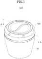
- FIG. 1is a schematic perspective view showing a drip container according to an embodiment of the present invention.
- FIG. 2is a schematic cross-sectional view taken along line AA of FIG. 1 .
- FIG. 3is a schematic exploded perspective view showing a drip container according to an embodiment of the present invention.
- FIG. 4is a schematic cross-sectional view showing a drip container in an exploded manner according to an embodiment of the present invention.
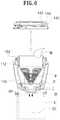
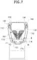
- FIGS. 5 to 7are schematic cross-sectional views showing a method of using a drip container according to an embodiment of the present invention.
- FIG. 8is a partial enlarged cross-sectional view for the schematic cross-sectional view of FIG. 2 .
- FIG. 9is a partial enlarged cross-sectional view for the schematic cross-sectional view of FIG. 2 .
- FIG. 10is a schematic perspective view showing a portable coffee drinking container according to another embodiment of the present invention.
- FIG. 11is a schematic exploded perspective view showing a portable coffee drinking container according to another embodiment of the present invention in a state in which a first opening and closing part is detached from a cover for dripping.
- FIG. 12is a schematic exploded perspective view showing a portable coffee drinking container according to another embodiment of the present invention in a state in which a second opening and closing part is detached from a drinking part for drinking drip coffee.
- FIG. 13is a schematic cross-sectional view taken along line BB of FIG. 10 .
- FIG. 14is a schematic exploded perspective view showing a portable coffee drinking container according to another embodiment of the present invention.
- FIG. 15is a schematic cross-sectional view showing a portable coffee drinking container in an exploded manner according to another embodiment of the present invention.
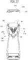
- FIGS. 16 to 20are schematic cross-sectional views showing a method of using a portable coffee drinking container according to another embodiment of the present invention.
- a drip containerincluding: a first main body providing a first space for dripping in which coffee grounds are stored, including an outlet hole through which drip coffee made by dripping discharges into a second space, and including an outward protrusion that protrudes outward from a region of an outer wall defining the first space; a cover surrounding the first main body so that the first main body is protected; a first opening and closing part detachably engaged with the cover so that opening and closing of the first space are adjusted; an inflow part including an inlet hole through which the drip coffee discharging through the outlet hole flows into the second space; and an elastic part elastically deformed due to pressure applied by the outward protrusion when the first opening and closing part is engaged, and placed between the first main body and the cover so that restoring force acts on the outward protrusion, wherein a position of the first main body is changed by interaction between the first opening and closing part and the elastic part, thereby adjusting communication between the outlet hole and the inlet hole.
- the outward protrusionapplies pressure to the elastic part and a distance between facing surfaces of the first main body and the inflow part is thus reduced, thereby cutting off the communication between the outlet hole and the inlet hole.
- the elastic partapplies the restoring force to the outward protrusion so as to return the first main body to its original position, thereby implementing the communication between the outlet hole and the inlet hole.
- a predetermined region at a lower portion of the first main bodymay be smaller in diameter than an upper portion of the first main body, the outward protrusion may be positioned at the predetermined region, and the elastic part may be positioned in a space between the first main body and the cover, the space being ensured because the diameter of the predetermined region is smaller than the diameter of the upper portion of the first main body.
- the drip containermay further include a filter including a filter net to enable dripping when placed in the first space, and including an anti-leakage ring that extends in a protruding manner upward from an upper portion of the filter, wherein the first opening and closing part may include a first ring member that is in contact with the anti-leakage ring to make an inner space of the filter airtight when the first opening and closing part is engaged with the cover.
- a filterincluding a filter net to enable dripping when placed in the first space, and including an anti-leakage ring that extends in a protruding manner upward from an upper portion of the filter
- the first opening and closing partmay include a first ring member that is in contact with the anti-leakage ring to make an inner space of the filter airtight when the first opening and closing part is engaged with the cover.
- the covermay include an anti-leakage end that extends in a protruding manner upward from a top end of the cover which is engaged with the first opening and closing part, and the first opening and closing part may include a second ring member that is in contact with the anti-leakage end to make an inner space of the cover airtight when the first opening and closing part is engaged with the cover.
- the drip containermay further include a closing part placed at at least one of facing surfaces of the first main body and the inflow part, wherein when the first opening and closing part is engaged with the cover, the closing part is in contact with both of the facing surfaces of the first main body and the inflow part and thus cuts off the communication between the outlet hole and the inlet hole.
- a portable coffee drinking containerincluding: a first main body providing a first space for dripping in which coffee grounds are stored, including an outlet hole through which drip coffee made by dripping discharges into a second space, and including an outward protrusion that protrudes outward from a region of an outer wall defining the first space; a second main body providing the second space, and including an inlet hole through which the drip coffee discharging through the outlet hole flows into the second space; a cover surrounding the first main body and the second main body so that the first main body and the second main body are placed inside the cover; a first opening and closing part detachably engaged with the cover so that opening and closing of the first space in which the coffee grounds are stored are adjusted; and an elastic part elastically deformed due to pressure applied by the outward protrusion when the first opening and closing part is engaged, and placed between the first main body and the cover so that restoring force acts on the outward protrusion, wherein a position of the first main body is changed by interaction
- the first opening and closing partmay be detached from the cover so that the drip coffee flows into the second space through the outlet hole and the inlet hole, and then the first opening and closing part may be engaged with the cover so that the communication between the outlet hole and the inlet hole is cut off, and the cover may enable the first main body to be positioned in a direction of gravity from the second main body, so that the drip coffee flowing into the second space can be drunk.
- the outward protrusionapplies pressure to the elastic part and a distance between facing surfaces of the first main body and the inflow part is thus reduced, thereby cutting off the communication between the outlet hole and the inlet hole.
- the elastic partapplies the restoring force to the outward protrusion so as to return the first main body to its original position, thereby implementing the communication between the outlet hole and the inlet hole.
- a predetermined region at a first side of the first main bodymay be smaller in diameter than a second side of the first main body which is positioned in a direction pointing away from the second main body with respect to the predetermined region, the outward protrusion may be positioned at the predetermined region, and the elastic part may be positioned in a space between the first main body and the cover, the space being ensured because the diameter of the predetermined region is smaller than the diameter of the second side.
- the portable coffee drinking containermay further include: a filter including a filter net to enable dripping when placed in the first space, and including an anti-leakage ring that extends in a protruding manner from a first side of the filter in a direction pointing away from the second main body, wherein the first opening and closing part may include a first ring member that is in contact with the anti-leakage ring to make an inner space of the filter airtight when the first opening and closing part is engaged with the cover.
- the covermay include an anti-leakage end that extends in a protruding manner from a first side of the cover which is engaged with the first opening and closing part, in a direction pointing away from the second main body, and the first opening and closing part may include a second ring member that is in contact with the anti-leakage end to make an inner space of the cover airtight when the first opening and closing part is engaged with the cover.
- the portable coffee drinking containermay further include: a closing part placed at at least one of facing surfaces of the first main body and the second main body, wherein the closing part may be in contact with both of the facing surfaces of the first main body and the second main body due to pressure applied by the first opening and closing part to the filter, and may thus cut off the communication between the outlet hole and the inlet hole.
- the portable coffee drinking containermay further include: a drinking part detachably engaged with the second main body, and including a drinking hole through which the drip coffee flowing into the second space discharges to outside for drinking, and a vent hole for adjusting pressure so that the drip coffee discharges through the drinking hole; and a drinking adjusting part detachably engaged with the drinking part to adjust opening and closing of the drinking hole and the vent hole.
- the drinking adjusting partmay include a close-contact part that is in close contact with the drinking hole and the vent hole and thus closes the drinking hole and the vent hole when the drinking adjusting part is inserted into the drinking part, and the close-contact part may have elasticity, and may have a portion that corresponds to the drinking hole and the vent hole and is formed in multiple layers.
- the portion of the close-contact partmay be formed in the multiple layers spaced apart from each other.
- FIG. 1is a schematic perspective view showing a drip container according to an embodiment of the present invention.
- FIG. 2is a schematic cross-sectional view taken along line AA of FIG. 1 .
- FIG. 3is a schematic exploded perspective view showing a drip container according to an embodiment of the present invention.
- FIG. 4is a schematic cross-sectional view showing a drip container in an exploded manner according to an embodiment of the present invention.
- a drip container 100is a type of dripper capable of making drip coffee by pouring hot water onto coffee grounds P.
- the drip container 100may include: a first main body 110 providing a first space S 1 for dripping in which the coffee grounds P (see FIG. 6 ) are stored; a cover 130 surrounding the first main body 110 so that the first main body 110 is protected from the outside; a first opening and closing part 140 detachably engaged with the cover 130 ; and an inflow part 150 through which the drip coffee flows into a second space S 2 (see FIG. 6 ).
- the second space S 2may refer to a space outside the drip container 100 according to an embodiment of the present invention, and may refer to, for example, an inner space of a type of cup C (see FIG. 5 ) that receives the drip coffee flowing out of the drip container 100 .
- the first main body 110may include an outlet hole H 1 through which the drip coffee made by dripping discharges into the second space S 2 .
- the outlet hole H 1may be formed at the bottom surface of the first main body 110 in a penetrating manner.
- the outlet hole H 1is not limited in number, but preferably, multiple outlet holes are radially formed.
- the bottom surface of the first main body 110may be formed in a shape in which the top is wide and the bottom is narrow, for example, a funnel.
- the drip coffee made by drippingnaturally passes through the outlet hole H 1 .
- the first main body 110may include a stepped wall 113 extending in a protruding manner upward from the upper surface of the first main body 110 .
- the stepped wall 113may make the inside of the drip container 100 airtight when being combined with the first opening and closing part 140 .
- the cover 130may serve as an external appearance of the drip container 100 according to an embodiment of the present invention, and may be an element with which the first opening and closing part 140 is detachably engaged.
- the first opening and closing part 140may be detachably engaged with the cover 130 and may adjust the opening and the closing of the first space S 1 for storing the coffee grounds P.
- the first opening and closing part 140may be engaged with the cover 130 in a screw-type fastening manner as shown in the drawings, but no limitation thereto is imposed.
- the first opening and closing part 140may be engaged with the cover 130 in a forcibly interlocking manner.
- the inflow part 150may include the inlet hole H 2 through which the drip coffee discharging through the outlet hole H 1 flows into the second space S 2 . Placed in the direction of gravity from the first main body 110 , the inflow part 150 enables the drip coffee to flow into the second space S 2 .
- the inflow part 150may be formed in an integrated manner with the cover 130 , but no limitation thereto is imposed.
- the inflow part 150may be formed as a separate member.
- the cover 130may include an anti-leakage end 133 .
- the anti-leakage end 133may make the inside of the drip container 100 airtight when being combined with the first opening and closing part 140 .
- the drip container 100may include a filter 160 that enables dripping when placed in the first space S 1 .
- the filter 160may include a seated portion 162 so that the filter 160 is positioned at a predetermined position within the first space S 1 .
- the seated portion 162protrudes from the outer surface and is seated on a stepped portion 112 formed at the inner surface of the first main body 110 .
- the filter 160may include: a net providing part 166 on which a filter net 164 for dripping is formed; and an anti-inflow part 168 formed extending from the net providing part 166 so that water poured to the inside of the net providing part 166 is prevented from flowing into the second space S 2 without passing through the coffee grounds P.
- the seated portion 162may be formed protruding from the outer surface of the anti-inflow part 168 .
- the net providing part 166may be in a shape in which the top is wide and the bottom is narrow, and the anti-inflow part 168 may be in a cylindrical shape, but no limitation thereto is imposed.
- the filter 160may include an anti-eccentricity part 169 protruding from the outer surface of the anti-inflow part 168 and being in contact with the inner surface of the first main body 110 so that when the filter 160 is placed in the first space S 1 , the filter 160 is prevented from being placed eccentrically within the first space S 1 .
- multiple anti-eccentricity parts 169may be formed spaced apart from each other along the circumferential direction, but no limitation thereto is imposed.
- the multiple anti-eccentricity parts 169may be formed continuously along the circumferential direction.
- the hot water poured onto the coffee grounds Pmay flow into a space between the first main body 110 and the anti-inflow part 168 due to carelessness, but may not flow into a space between the first main body 110 and the net providing part 166 by a first sealing part 161 .
- the first sealing part 161may be provided on the outer surface of the anti-inflow part 168 in such a manner as to be in contact with the first main body 110 , and may be made of a rubber material, or the like having elasticity.
- the filter 160may include an anti-leakage ring 163 extending upward.
- the anti-leakage ring 163may make the inside of the drip container 100 airtight when being combined with the first opening and closing part 140 .
- the communication between the outlet hole H 1 and the inlet hole H 2may be adjusted by the interaction between the first opening and closing part 140 and the cover 130 , which will be described below with reference to FIGS. 5 to 7 .
- FIGS. 5 to 7are schematic cross-sectional views showing a method of using a drip container according to an embodiment of the present invention.
- the first opening and closing part 140is detached from the cover 130 , and the filter 160 is inserted into the first space S 1 provided by the first main body 110 .
- the step of inserting the filter 160may be omitted.
- the seated portion 162is seated on the stepped portion 112 formed at the inner surface of the first main body 110 , so that the filter 160 is positioned at a predetermined position within the first space S 1 .
- the filter 160is prevented from being placed eccentrically within the first space S 1 .
- the filter 160is inserted into the first space S 1 , and the seated portion 162 is seated on the stepped portion 112 . Then, an appropriate amount of coffee grounds P is inserted into the filter 160 , and hot water W is poured onto the coffee grounds P.
- outlet hole H 1 and the inlet hole H 2may be in communication with each other, and as time passes, drip coffee DC is stored in the second space S 2 provided by the cup C.
- the usercan drink the drip coffee DC, and the user needs to cut off the communication between the outlet hole H 1 and the inlet hole H 2 .
- the userrotates the first opening and closing part 140 to engage it with the cover 130 .
- the first opening and closing part 140may adjust the communication between the outlet hole H 1 and the inlet hole H 2 by the interaction with the cover 130 .
- the communication between the outlet hole H 1 and the inlet hole H 2is implemented.
- the communication between the outlet hole H 1 and the inlet hole H 2is cut off.
- the closing part 170may be a type of rubber ring made of a material having elasticity, and it is obvious that the rubber ring should be made of a material harmless to humans.
- the first opening and closing part 140When the first opening and closing part 140 is engaged with the cover 130 , the first opening and closing part 140 applies pressure to the filter 160 by being in contact with the filter 160 .
- the first opening and closing part 140 being in contact with the filter 160may include a first ring member 142 having elasticity. Due to this, when the first opening and closing part 140 is engaged with the cover 130 , the first opening and closing part 140 gently applies pressure to the filter 160 .
- the first opening and closing part 140may include multiple ring members that include the first ring member 142 , and a second ring member 144 .
- the multiple ring membersfill gaps between the first opening and closing part 140 and the filter 160 being in contact with the first opening and closing part 140 , between the first opening and closing part 140 and the first main body 110 , or between the first opening and closing part 140 and the cover 130 , thereby blocking liquid from leaking through the upper portion of the drip container 100 .
- the seated portion 162 of the filter 160applies pressure to the stepped portion 112 of the first main body 110 .
- the position of the first main body 110is changed.
- the distance D between the facing surfaces of the first main body 110 and the inflow part 150is further reduced. Accordingly, the closing part 170 provided at the first main body 110 is moved toward the inflow part 150 , and is eventually in contact with the inflow part 150 .
- the closing part 170 being in contact with the inflow part 150serves as a type of partition that divides the outlet hole H 1 from the inlet hole H 2 . Eventually, the communication between the outlet hole H 1 and the inlet hole H 2 is cut off.
- the drip container 100may include an elastic part E that is elastically deformed due to the pressure applied by the first opening and closing part 140 to the filter 160 , when the first opening and closing part 140 is engaged with the cover 130 .
- the elastic part Emay be placed between the first main body 110 and the cover 130 . Before the first opening and closing part 140 is engaged with the cover 130 , the elastic part E maintains a normal state (see FIGS. 5 and 6 ) and thus supports the first main body 110 within the cover 130 .
- the elastic part Eis elastically deformed by the first main body 110 of which the position is changed due to the pressured applied by the filter 160 .
- the elastic part Ereturns the first main body 110 to its original position due to restoring force caused by the elastic deformation.
- the communication between the outlet hole H 1 and the inlet hole H 2is naturally implemented.
- any elastic part Emay be applicable with no limitation in shape and material, if the elastic part E is elastically deformed when the first opening and closing part 140 is engaged with the cover 130 , and if the elastic part E returns the first main body 110 to its original position due to restoring force caused by elastic deformation when the first opening and closing part 140 is detached from the cover 130 .
- the elastic part Emay be a rubber material.
- the elastic part Emay be a spring that surrounds the outside of the first main body 110 .
- the elastic part Emay be positioned on the upper portion of the cover 130 adjacent to the stepped portion so that the restoring force acts on the stepped portion 112 positioned at the top end of the first main body 110 .
- the elastic part Emay be positioned on the lower portion of the first main body 110 and the cover 130 .
- the first main body 110may include a second sealing part 114 that has elasticity to prevent impurities, or the like other than the drip coffee from flowing into the second space S 2 through the inlet hole H 2 .
- the second sealing part 114may be in contact with the inner surface of the cover 130 or the inner surface of the inflow part 150 when the first main body 110 is inserted into the cover 130 .
- FIG. 8is a partial enlarged cross-sectional view for the schematic cross-sectional view of FIG. 2 .
- the inside of the drip container 100is made airtight by the first ring member 142 and the second ring member 144 .
- the second ring member 144may be formed with a larger diameter than the first ring member 142 and may be provided in a shape that surrounds the first ring member 142 at the outside of the first ring member 142 .
- the anti-leakage ring 163may be in contact with and may press the first ring member 142 . Consequently, the liquid inside the filter 160 may be prevented from leaking to the outside through the first opening and closing part 140 .
- the liquid inside the filter 160may stay in a space between the filter 160 and the first main body 110 .
- the liquid in the spacealso needs to be prevented from leaking through the first opening and closing part 140 .
- the pressure applied by the first opening and closing part 140 to the first ring member 142may be transmitted to the seated portion 162 and the stepped portion 112 , so that the seated portion 162 and the stepped portion 112 are bonded tightly. Consequently, the liquid may be prevented from leaking through the first opening and closing part 140 from the space between the filter 160 and the first main body 110 .
- the second ring member 144may be in contact with and may press the anti-leakage end 133 .
- the second ring member 144is elastically deformed in a manner that fits to the shape of the anti-leakage end 133 due to the pressure, so that the second ring member 144 is in close contact with the anti-leakage end 133 without a gap. Consequently, the liquid may be prevented from leaking to the outside through the first opening and closing part 140 from the space between the filter 160 and the first main body 110 .
- the stepped wall 113extends upward. Therefore, when the first opening and closing part 140 is engaged, the stepped wall 113 is in close contact with the second ring member 144 . Thus, the liquid may be prevented from leaking to the outside through the first opening and closing part 140 from the space between the filter 160 and the first main body 110 .
- FIG. 9is a partial enlarged cross-sectional view for the schematic cross-sectional view of FIG. 2 .
- the elastic part Emay be positioned between the first main body 110 and the cover 130 .
- the diameter of the circular cross sectiondecreases as it goes downward.
- a space in which the elastic part E is capable of moving between the first main body 110 and the cover 130may be ensured.
- the first main body 110may include an outward protrusion 116 protruding outward along the circumference of the first main body 110 so as to provide a surface on which the restoring force of the elastic part E acts.
- the first main body 110When pressure is applied by the first opening and closing part 140 , the first main body 110 is moved downward, so that the elastic part E interposed between the outward protrusion 116 and the lower portion of the cover 130 is elastically deformed.
- the elastic part EBy the outward protrusion 116 , the restoring force of the elastic part E may be effectively transmitted to the first main body 110 , and the elastic part E may be stably interposed between the first main body 110 and the cover 130 .
- the lower portion of the cover 130may be provided with an elastic-part support 135 that protrudes inward from the inner surface of the cover 130 .
- the elastic-part support 135supports the elastic part E from below, so that the elastic-part support 135 and the outward protrusion 116 , which supports the elastic part E from above, stably fix the elastic part E together.
- the elastic-part support 135may provide a surface on which the restoring force of the elastic part E acts.
- FIG. 10is a schematic perspective view showing a portable coffee drinking container according to another embodiment of the present invention.
- FIG. 11is a schematic exploded perspective view showing a portable coffee drinking container according to another embodiment of the present invention in a state in which a first opening and closing part is detached from a cover for dripping.
- FIG. 12is a schematic exploded perspective view showing a portable coffee drinking container according to another embodiment of the present invention in a state in which a second opening and closing part is detached from a drinking part for drinking drip coffee.
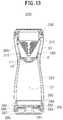
- FIG. 13is a schematic cross-sectional view taken along line BB of FIG. 10 .
- FIG. 14is a schematic exploded perspective view showing a portable coffee drinking container according to another embodiment of the present invention.
- FIG. 15is a schematic cross-sectional view showing a portable coffee drinking container in an exploded manner according to another embodiment of the present invention.
- a portable coffee drinking container 200uses the drip container 100 according to the embodiment of the present invention described above with reference to FIGS. 1 to 9 .
- the description overlapping with that of the drip container 100 according to the embodiment of the present inventionwill be omitted.
- the portable coffee drinking container 200is a container that enables drinking the drip coffee DC (see FIGS. 17 and 18 ) made by pouring hot water onto the coffee grounds P (see FIG. 17 ) and by filtering the hot water.
- the portable coffee drinking container 200may be a new-concept tumbler in which a dripper and a drinking container are implemented.
- the portable coffee drinking container 200is a container that enables drinking the drip coffee DC made by pouring water onto the coffee grounds P.
- the portable coffee drinking container 200may include a first main body 210 , a second main body 220 , a cover 230 , a first opening and closing part 240 , a filter 260 , and the like.
- the first main body 210may provide a first space S 1 for dripping in which coffee grounds P are stored, and may include an outlet hole H 1 through which the drip coffee DC made by dripping discharges into a second space S 2 .
- the second main body 220may provide the second space S 2 , and may include an inlet hole H 2 through which the drip coffee DC discharging through the outlet hole H 1 flows into the second space S 2 .
- the outlet hole H 1may be formed at the bottom surface of the first main body 210
- the inlet hole H 2may be formed at the top surface of the second main body 220 .
- the first main body 210 and the second main body 220may be surrounded by the cover 230 .
- the first main body 210 and the second main body 220may be placed inside the cover 230 .
- the cover 230may serve as an external appearance of the portable coffee drinking container 200 , and may be an element with which the first opening and closing part 240 is detachably engaged.
- the portable coffee drinking container 200may include a drinking part 280 that enables drinking the drip coffee stored in the second space S 2 .
- the drinking part 280may be detachably engaged with the second main body 220 in a screw-type fastening manner, but no limitation thereto is imposed.
- the drinking part 280may be engaged with the second main body 220 in a forcibly interlocking manner.
- the drinking part 280may include: a drinking hole 282 through which the drip coffee flowing into the second space S 2 discharges to the outside for drinking; and a vent hole 284 for adjusting pressure so that the drip coffee discharges through the drinking hole 282 .
- the opening and the closing of the drinking hole 282 and the vent hole 284may be adjusted by a drinking adjusting part 290 detachably engaged with the drinking part 280 .
- the drinking adjusting part 290When the drinking adjusting part 290 is inserted into the drinking part 280 , the drinking adjusting part 290 is in close contact with the drinking hole 282 and the vent hole 284 . Thus, the drinking hole 282 and the vent hole 284 may be closed.
- the drinking adjusting part 290may include: a close-contact part 292 that closes the drinking hole 282 and the vent hole 284 by being in close contact with the drinking hole 282 and the vent hole 284 ; and a support 294 supporting the close-contact part 292 .
- the close-contact part 292may be made of a rubber material having elasticity, and may have a portion that corresponds to the drinking hole 282 and the vent hole 284 and is formed in multiple layers.
- the portion of the close-contact part 292may be formed in the multiple layers spaced apart from each other.
- the drinking adjusting part 290when the drinking adjusting part 290 is inserted into the drinking part 280 , the drinking hole 282 and the vent hole 284 are stably closed due to the close-contact part 292 having the portion formed in the multiple spaced layers.
- the drinking adjusting part 290may be interlocked with the second opening and closing part 295 that is detachably engaged with the drinking part 280 in a screw-type fastening manner, or the like.
- the drinking adjusting part 290may keep connected with the second opening and closing part 295 .
- the second opening and closing part 295 and the drinking adjusting part 290may include a locking portion 296 and a locked portion 297 , respectively.
- the locking portion 296 and the locked portion 297may be implemented as a groove and a protruding structure inserted into the groove, and vice versa. Other known means for connection may be applicable.
- the drinking adjusting part 290is inserted into the drinking part 280 and naturally closes the drinking hole 282 and the vent hole 284 .
- the drinking adjusting part 290when the second opening and closing part 295 is fastened to the drinking part 280 in a screwing manner, the drinking adjusting part 290 also rotates with the second opening and closing part 295 simultaneously. This is because a protrusion 291 formed at the support 294 is inserted into a depression 293 formed at the second opening and closing part 295 .
- FIGS. 16 to 20are schematic cross-sectional views showing a method of using a portable coffee drinking container according to another embodiment of the present invention.
- the first opening and closing part 240is detached from the cover 230 , and the filter 260 is inserted into the first space S 1 provided by the first main body 210 .
- the step of inserting the filter 260may be omitted.
- the seated portion 262is seated on the stepped portion 212 formed at the inner surface of the first main body 210 , so that the filter 260 is positioned at a predetermined position within the first space S 1 .
- the filter 260is prevented from being placed eccentrically within the first space S 1 .
- the filter 260is inserted into the first space S 1 , and the seated portion 262 is seated on the stepped portion 212 . Then, an appropriate amount of coffee grounds P is inserted into the filter 260 , and hot water W is poured onto the coffee grounds P.
- the outlet hole H 1 and the inlet hole H 2may be in communication with each other, because the first opening and closing part 240 is detached from the cover 230 .
- the drip coffee DCis stored in the second space S 2 provided by the second main body 220 .
- the first opening and closing part 240is rotated and engaged with the cover 230 as shown in FIG. 18 .
- the cover 230is rotated to interchange the position of the first main body 210 and the position of the second main body 220 , as shown in FIG. 19 .
- the cover 230enables the first main body 210 to be positioned in the direction of gravity from the second main body 220 , so that the drip coffee flowing into the second space S 2 can be drunk.
- the first ring member 242is in close contact with the top end of the filter, and the second ring member 244 is in close contact with the top end of the cover 230 or the top end of the first main body 210 , thereby resulting in a sealing state and preventing leakage of the liquid.
- the userdetaches the second opening and closing part 295 from the drinking part 280 and drinks the drip coffee DC through the drinking hole 282 .
- the drinking adjusting part 290is naturally detached from the drinking part 280 when the second opening and closing part 295 is detached from the drinking part 280 .
Landscapes
- Engineering & Computer Science (AREA)
- Food Science & Technology (AREA)
- Apparatus For Making Beverages (AREA)
Abstract
Description
- 100: Drip container
- 200: Portable coffee drinking container
- 110,210: First main body
- 220: Second main body
- 130,230: Cover
- 140,240: First opening and closing part
- 160,260: Filter
- 295: Second opening and closing part
- 113: Stepped wall
- 116,216: Outward protrusion
- 133: Anti-leakage end
- 135: Elastic-part support
- 142: First ring member
- 144: Second ring member
- 163: Anti-leakage ring
- E: Elastic part
Claims (13)
Applications Claiming Priority (3)
| Application Number | Priority Date | Filing Date | Title |
|---|---|---|---|
| KR1020180013951AKR102071046B1 (en) | 2018-02-05 | 2018-02-05 | Dripper and portable coffee drinking tumbler |
| KR10-2018-0013951 | 2018-02-05 | ||
| PCT/KR2019/001481WO2019151837A1 (en) | 2018-02-05 | 2019-02-01 | Drip container and portable coffee drinking container |
Publications (2)
| Publication Number | Publication Date |
|---|---|
| US20210030190A1 US20210030190A1 (en) | 2021-02-04 |
| US11013359B2true US11013359B2 (en) | 2021-05-25 |
Family
ID=67479799
Family Applications (1)
| Application Number | Title | Priority Date | Filing Date |
|---|---|---|---|
| US16/967,126Expired - Fee RelatedUS11013359B2 (en) | 2018-02-05 | 2019-02-01 | Drip container and portable coffee drinking container |
Country Status (4)
| Country | Link |
|---|---|
| US (1) | US11013359B2 (en) |
| KR (1) | KR102071046B1 (en) |
| CN (1) | CN111655091A (en) |
| WO (1) | WO2019151837A1 (en) |
Cited By (2)
| Publication number | Priority date | Publication date | Assignee | Title |
|---|---|---|---|---|
| US11659952B2 (en) | 2005-04-18 | 2023-05-30 | BL Patens, LLC | Cold brew beverage brewing systems |
| US12318032B2 (en) | 2005-04-18 | 2025-06-03 | Bl Patents, Llc | Cold brew beverage brewing systems |
Families Citing this family (6)
| Publication number | Priority date | Publication date | Assignee | Title |
|---|---|---|---|---|
| CN115868790B (en)* | 2021-09-29 | 2025-07-22 | 广东美的生活电器制造有限公司 | Filter device, food processor, control method and device thereof, and readable storage medium |
| CN115868791B (en)* | 2021-09-29 | 2025-07-22 | 广东美的生活电器制造有限公司 | Filter assembly, filter device, food processor, and control method and device thereof |
| CN115868792B (en)* | 2021-09-29 | 2025-07-22 | 广东美的生活电器制造有限公司 | Food processor, method of controlling the same, apparatus for controlling the same, and readable storage medium storing the apparatus |
| CN115868837B (en)* | 2021-09-29 | 2025-08-01 | 广东美的生活电器制造有限公司 | Food processor, method of controlling the same, apparatus for controlling the same, and readable storage medium storing the apparatus |
| CN114190769A (en)* | 2021-12-23 | 2022-03-18 | 广东德豪锐拓显示技术有限公司 | Air pressure adjusting device, coffee machine and coffee liquid preparation method |
| USD1086798S1 (en) | 2023-01-26 | 2025-08-05 | Zhiji Xing | Pour over coffee dripper |
Citations (180)
| Publication number | Priority date | Publication date | Assignee | Title |
|---|---|---|---|---|
| US316885A (en)* | 1885-04-28 | James heevet dumont | ||
| US323637A (en)* | 1885-08-04 | Oil-strainer | ||
| US347581A (en)* | 1886-08-17 | Milk-strainer | ||
| US426489A (en)* | 1890-04-29 | Filter | ||
| US433659A (en)* | 1890-08-05 | Mekhorn | ||
| US604984A (en)* | 1898-05-31 | Filter | ||
| US881564A (en)* | 1907-06-25 | 1908-03-10 | Gustav Epstein | Strainer for coffee-urns. |
| US942121A (en)* | 1908-08-15 | 1909-12-07 | May C White | Strainer. |
| US950211A (en)* | 1909-06-09 | 1910-02-22 | Joseph D Reymore | Apparatus for filtering milk. |
| US967905A (en)* | 1910-03-26 | 1910-08-23 | Virgil B Hagg | Water-filter. |
| US989752A (en)* | 1910-12-03 | 1911-04-18 | Frank Ansley | Strainer-top for milk-pails. |
| US1023664A (en)* | 1911-03-20 | 1912-04-16 | Asbury F Laity | Milk-strainer. |
| US1044074A (en)* | 1911-03-08 | 1912-11-12 | William W Nugent | Filter. |
| US1053573A (en)* | 1912-05-07 | 1913-02-18 | Nora K Clemm | Kitchen utensil. |
| US1068900A (en)* | 1912-05-14 | 1913-07-29 | William B Herd | Milking-pail. |
| US1104773A (en)* | 1913-07-26 | 1914-07-28 | Ira Earnest Bradshaw | Sanitary milking vessel. |
| US1216112A (en)* | 1916-11-08 | 1917-02-13 | Derk Greven | Strainer for liquids. |
| US1317717A (en)* | 1919-10-07 | Planograpii co | ||
| US1501073A (en)* | 1922-04-17 | 1924-07-15 | Stead Aquila Moore | Funnel strainer |
| US1536890A (en)* | 1923-07-21 | 1925-05-05 | Gustav P Lagemann | Milk-strainer attachment |
| US1601987A (en)* | 1925-12-14 | 1926-10-05 | Thomas J Topper | Coffee container for urns |
| US1701194A (en)* | 1928-03-10 | 1929-02-05 | Rosenstein Fritz | Beverage maker and dispenser |
| US1876474A (en)* | 1932-09-06 | Device fob making dbip copeee | ||
| US1889111A (en)* | 1929-02-23 | 1932-11-29 | Serr William | Flavor dispenser cup |
| US1895857A (en)* | 1931-09-16 | 1933-01-31 | Louis R Mockbee | Percolator |
| US2000309A (en)* | 1933-03-01 | 1935-05-07 | West Bend Aluminum Co | One cup coffee maker |
| US2003658A (en)* | 1933-08-07 | 1935-06-04 | Lawrence J Thomas | Strainer |
| US2069229A (en)* | 1936-06-29 | 1937-02-02 | Ferris Robert | Coffee making apparatus |
| US2285114A (en)* | 1938-11-16 | 1942-06-02 | Ferris Robert | Coffee making apparatus |
| US3010583A (en)* | 1959-10-23 | 1961-11-28 | Millipore Filter Corp | Fluid sampling device |
| US3083101A (en)* | 1959-04-06 | 1963-03-26 | Noury Jean | Refill for filtration coffee-pot |
| US3420675A (en)* | 1964-10-26 | 1969-01-07 | Nicholas J Costas | Disposable coffee cartridge |
| US3694235A (en)* | 1970-03-20 | 1972-09-26 | Sidney Siegel | Disposable food-vending package |
| US3695168A (en)* | 1970-06-02 | 1972-10-03 | George H Van Brunt | Drip coffee maker |
| US3924741A (en)* | 1975-03-04 | 1975-12-09 | Gibson Ass Inc | Two-compartment container |
| US3931756A (en)* | 1972-09-05 | 1976-01-13 | Brunt George H Van | Filter area limiting device for drip coffee makers with micropore filter |
| US3937134A (en)* | 1971-12-15 | 1976-02-10 | Douwe Egberts Tabaksfabriek-Koffiebranderijen-Theehandel B.V. | Coffee filtering |
| JPS515319B1 (en) | 1968-04-30 | 1976-02-19 | ||
| US3971305A (en)* | 1975-03-27 | 1976-07-27 | Daswick Alexander C | Disposable beverage brewer |
| US3985069A (en)* | 1973-12-03 | 1976-10-12 | Cavalluzzi Frank J | Coffee beverage drip brewer |
| US4021354A (en)* | 1975-10-31 | 1977-05-03 | Bristol-Myers Company | Pressure filter |
| US4167136A (en)* | 1977-07-25 | 1979-09-11 | Chupurdy Garry C | Beverage brewer |
| US4251366A (en)* | 1979-06-18 | 1981-02-17 | Simon Timothy M | Adapter for laboratory filter |
| US4255265A (en)* | 1979-04-23 | 1981-03-10 | Maxs Ag | Reusable coffee filter |
| US4256585A (en)* | 1979-04-23 | 1981-03-17 | Maxs Ag | Coffee filter with drip tray |
| US4301010A (en)* | 1980-03-10 | 1981-11-17 | Spectrum Medical Industries, Inc. | Vacuum filter |
| US4354427A (en)* | 1980-06-30 | 1982-10-19 | W. M. Still & Sons Limited | Coffee and tea making or brewing apparatus |
| US4357240A (en)* | 1981-02-27 | 1982-11-02 | Sybron Corporation | Disposable, one-piece filter unit |
| US4417504A (en)* | 1981-04-02 | 1983-11-29 | Mitsumoto Coffee Co., Ltd. | Regular coffee set |
| US4439319A (en)* | 1982-07-16 | 1984-03-27 | Rock John G | Receptacle for the collection of medical specimens and the like |
| US4446158A (en)* | 1982-06-08 | 1984-05-01 | English Philip H | Apparatus for making individual beverage quantities |
| US4520716A (en)* | 1984-03-19 | 1985-06-04 | Hayes Susan M | Drip-type coffee making apparatus |
| US4577080A (en)* | 1985-03-19 | 1986-03-18 | Gee Associates | Coffee maker adapted for use in a microwave oven |
| US4614585A (en)* | 1981-03-02 | 1986-09-30 | Sybron Corporation | Frangible bonded disposable filtration unit with recoverable filter |
| US4642443A (en)* | 1981-11-16 | 1987-02-10 | Northland Aluminum Products, Inc. | Apparatus for brewing coffee in microwave ovens |
| US4644856A (en)* | 1984-01-10 | 1987-02-24 | Robert Krups Stiftung & Co. Kg. | Apparatus for brewing espresso coffee |
| US4673501A (en)* | 1985-11-19 | 1987-06-16 | Miles Laboratories, Inc. | Bottle top filter |
| US4689147A (en)* | 1985-09-27 | 1987-08-25 | Nalge Company | Plastic filter assembly |
| US4702834A (en)* | 1986-06-17 | 1987-10-27 | Nalge Company | Plastic filter units having a weld cellulose filter |
| US4731177A (en)* | 1986-12-30 | 1988-03-15 | Hemman Edward B | Multi-stage straining apparatus |
| JPS6343558B2 (en) | 1983-10-18 | 1988-08-31 | Mitsui Constr | |
| US4783318A (en)* | 1987-10-02 | 1988-11-08 | The State Of Minnesota | Apparatus for environmental leaching testing |
| US4806369A (en)* | 1986-11-07 | 1989-02-21 | Thompson Owen E | Method and apparatus for making an infusion |
| US4833979A (en)* | 1987-06-23 | 1989-05-30 | Zanussi Grandi Impianti S.P.A. | Automatic machine for making coffee or similar beverages |
| US4843954A (en)* | 1987-05-26 | 1989-07-04 | Robert Krups Stiftung & Co. Kg | Tea making machine |
| US4882982A (en)* | 1986-10-08 | 1989-11-28 | Spidem S.R.L. | Percolator holding pan for espresso coffee making machines |
| US4894155A (en)* | 1988-04-14 | 1990-01-16 | Nalge Cmpany | Single membrane disc supporting upper and lower membranes |
| US4997015A (en)* | 1988-10-17 | 1991-03-05 | Black & Decker, Inc. | Brew through lid for coffee maker |
| US5067395A (en)* | 1989-02-09 | 1991-11-26 | Eberhard Timm | Device for preparing hot drinks |
| US5186828A (en)* | 1992-02-14 | 1993-02-16 | Mankin Gary L | Paint strainer kit |
| US5192424A (en)* | 1991-12-05 | 1993-03-09 | Isp Investments Inc. | Filter identification device |
| US5234585A (en)* | 1991-12-19 | 1993-08-10 | Zuk, Incorporated | Vacuum filtration device |
| US5243164A (en)* | 1990-12-14 | 1993-09-07 | Gee Associates | Beverage maker |
| US5259295A (en)* | 1990-10-04 | 1993-11-09 | Eberhard Timm | Container for the preparation of hot drinks |
| US5309823A (en)* | 1992-04-15 | 1994-05-10 | Allen Dillis V | Coffee brewing assembly |
| US5318703A (en)* | 1993-05-26 | 1994-06-07 | Ultrapure Systems, Inc. | Water filter module |
| US5325996A (en)* | 1993-04-07 | 1994-07-05 | Gondal Pty. Ltd. | Beverage vessel with flavoring concentrate dispenser |
| US5353961A (en)* | 1993-01-15 | 1994-10-11 | Reseal International Limited Partnership | Dual chamber dispenser |
| JPH06343558A (en) | 1993-06-02 | 1994-12-20 | Sharp Corp | Liquid leak prevention device for coffee makers |
| US5393548A (en)* | 1993-05-26 | 1995-02-28 | Ultrapure Systems, Inc. | Method of making coffee using water filtration device |
| US5411661A (en)* | 1993-05-26 | 1995-05-02 | Ultrapure Systems, Inc. | Water filter module |
| US5433328A (en)* | 1994-05-17 | 1995-07-18 | Baron; Moises S. | Baby bottle extension assembly having storage chamber and release mechanism |
| US5490927A (en)* | 1995-01-04 | 1996-02-13 | Filtron Technology Corporation | Filtration apparatus with membrane filter unit |
| US5590581A (en)* | 1995-03-09 | 1997-01-07 | Maxs Ag | Assembly kit for a filter coffee maker |
| US5603900A (en)* | 1995-05-19 | 1997-02-18 | Millipore Investment Holdings Limited | Vacuum filter device |
| US5632194A (en)* | 1996-10-30 | 1997-05-27 | Lin; Yu-Mei | Infusion maker |
| US5632193A (en)* | 1996-08-28 | 1997-05-27 | Shen; Shun-Tsung | Apparatus for making tea |
| US5638968A (en)* | 1996-02-26 | 1997-06-17 | Baron; Moises S. | Baby bottle extension assembly having storage chamber and release mechanism |
| US5652008A (en)* | 1993-05-26 | 1997-07-29 | Ultrapure Systems, Inc. | Universal water filtration device and method of filtering water |
| USD381866S (en)* | 1996-01-11 | 1997-08-05 | Yvan St-Gelais | Coffeemaker for a cup |
| US5699719A (en)* | 1995-11-21 | 1997-12-23 | Healthometer, Inc. | Thermal carafe brewing device with brew-through lid |
| US5725765A (en)* | 1996-11-18 | 1998-03-10 | Shen; Shun-Tsung | Tea maker structure |
| US5775206A (en)* | 1996-08-27 | 1998-07-07 | St-Gelais; Yvan | Coffeemaker with a permanent filter |
| US5813317A (en)* | 1997-12-15 | 1998-09-29 | Chang; Keng-Hao | Brewing pot |
| US5826493A (en)* | 1997-11-04 | 1998-10-27 | Peo-Wu Tien | Infusion coffee maker |
| US5832809A (en)* | 1995-11-09 | 1998-11-10 | Gras; Marlene | Microwave operated coffee maker |
| US5853581A (en)* | 1997-04-11 | 1998-12-29 | Rayborn; Redrick D. | Drain bucket |
| US5855160A (en)* | 1996-08-29 | 1999-01-05 | Shen; Shun-Tsung | Tea maker |
| US5862739A (en)* | 1997-11-28 | 1999-01-26 | Lin; Yu-Mei Tien | Infusion maker |
| US5914045A (en)* | 1995-12-26 | 1999-06-22 | Palmer; Carl W | Portable water filtration system and method |
| US5943946A (en)* | 1998-09-29 | 1999-08-31 | Chen; Uei-Tsai | Infusing device for a beverage |
| US5948246A (en)* | 1991-12-19 | 1999-09-07 | Zuk, Jr.; Peter | Vacuum filtration device |
| US5947004A (en)* | 1998-07-24 | 1999-09-07 | Huang; Yen-Wen | Infusion maker |
| US6045254A (en)* | 1996-12-26 | 2000-04-04 | M.L.I.S. Projects Ltd. | Container having two or more compartments |
| US6058827A (en)* | 1999-06-02 | 2000-05-09 | Lin Tien; Yu-Mei | Structure of a tea flushing device |
| US6069996A (en)* | 1995-01-26 | 2000-05-30 | Timm; Eberhard | Device for heating a drinkable liquid |
| US6103116A (en)* | 1998-10-01 | 2000-08-15 | Kx Industries, L.P. | Collapsible filter |
| US6164190A (en)* | 1999-12-16 | 2000-12-26 | Tien Lin; Yu Mei | Tea infusing device |
| US6182554B1 (en)* | 1999-01-19 | 2001-02-06 | Keurig, Inc. | Beverage filter cartridge holder |
| US20010009127A1 (en)* | 2000-01-20 | 2001-07-26 | Eberhard Timm | Appliance for the preparation of hot beverages |
| US6276262B1 (en)* | 2000-04-26 | 2001-08-21 | Jason C. S. Chen | System and method of Chinese tea brewing |
| US6327965B1 (en)* | 2000-07-03 | 2001-12-11 | Yu-Mei Lin Tien | Safety and drain-preventing infusing tea maker |
| US6358730B1 (en)* | 1997-01-29 | 2002-03-19 | Pall Corporation | Filtration assembly and culture device |
| US6477942B1 (en)* | 2002-05-24 | 2002-11-12 | Chuen Lan Guu | Beverage infusion container |
| US6481337B1 (en)* | 2002-05-24 | 2002-11-19 | Chuen Lan Guu | Controlling mechanism of beverage infusion container |
| US6494128B1 (en)* | 2002-05-08 | 2002-12-17 | Hong Chao Yu | Infusing container |
| US20040194631A1 (en)* | 2001-04-30 | 2004-10-07 | Pope Randy D. | Variable flow spray system |
| US6805040B1 (en)* | 2003-06-26 | 2004-10-19 | Richard Chang | Tea maker |
| US6913152B2 (en)* | 2000-12-04 | 2005-07-05 | Peter Zuk, Jr. | Disposable vacuum filtration apparatus capable of detecting microorganisms and particulates in liquid samples |
| US20050189288A1 (en)* | 2004-02-19 | 2005-09-01 | David Hershberger | Manifold and filter assembly with filter basket |
| US20050189290A1 (en)* | 2004-03-01 | 2005-09-01 | Miles Maiden | Portable filter cap |
| US20050242529A1 (en)* | 2004-04-06 | 2005-11-03 | Lg Electronics Inc. | Sealing structure for refrigerator |
| US20050265903A1 (en)* | 2004-05-28 | 2005-12-01 | Julian Ross | Apparatus and delivery of medically pure oxygen |
| US7073428B2 (en)* | 2004-11-15 | 2006-07-11 | Ming-Chi Chung | Automatic tea maker |
| US7150219B2 (en)* | 2001-05-11 | 2006-12-19 | De'longhi S.P.A. | Filter cup for coffee machine and coffee-making process |
| US7182864B2 (en)* | 2002-06-07 | 2007-02-27 | Baldwin Filters, Inc. | Housing for environmentally friendly filter cartridge |
| US20090056557A1 (en)* | 2007-08-31 | 2009-03-05 | Shin-Shuoh Lin | Multi-function beverage brewer and cup |
| US20090101023A1 (en)* | 2006-04-03 | 2009-04-23 | Mermaid Co., Ltd. | Fryer |
| US20090178573A1 (en)* | 2008-01-16 | 2009-07-16 | Chih-Teng Pan | Dual Mode Tea Flask |
| US20090199518A1 (en)* | 2006-08-25 | 2009-08-13 | Louis Deuber | Means for penetrating a portion packaging containing an extraction product, device for extracting the extraction product contained in the portion packaging, and method for producing the means |
| US20090294385A1 (en)* | 2005-05-17 | 2009-12-03 | Universal Bio Research Co., Ltd | Filtration method, filter-incorporated tip, and filtration device |
| US20100031827A1 (en)* | 2008-08-06 | 2010-02-11 | Ying-Hsu Lai | Tea maker |
| US7661538B1 (en)* | 2001-05-31 | 2010-02-16 | Roush Life Science, LLC | Disposable vacuum filtration funnel with integral prefilter |
| US7670479B2 (en)* | 2004-05-24 | 2010-03-02 | PUR Water Purification, Inc. | Fluid container having an additive dispensing system |
| US20100212509A1 (en)* | 2009-02-20 | 2010-08-26 | Pao-Wu Tien | Safety and guide type brewing kettle |
| US20100224078A1 (en)* | 2009-03-04 | 2010-09-09 | Aly Khalifa | Beverage filtering system |
| US7798333B2 (en)* | 2005-09-02 | 2010-09-21 | Roush Life Sciences, Llc | Systems, apparatus and methods for vacuum filtration |
| US7836820B2 (en)* | 2007-09-19 | 2010-11-23 | Sunbeam Products, Inc. | Brewing device having a delayed release mechanism |
| US7856922B2 (en)* | 2007-04-25 | 2010-12-28 | Eddy Tjen | Instant extraction cup |
| US20110005400A1 (en)* | 2009-07-08 | 2011-01-13 | Pao-Wu Tien | Coffee making kettle using venturi |
| JP4658935B2 (en) | 2003-08-25 | 2011-03-23 | ネステク ソシエテ アノニム | Apparatus and method for making a beverage from food material contained in a capsule |
| US7926414B1 (en)* | 2008-01-15 | 2011-04-19 | Justine Marie Wolcott | Material for a manual drip coffee cone |
| US8039036B2 (en)* | 2003-08-25 | 2011-10-18 | Sara Lee/De N.V. | Preparation of a beverage suitable for consumption |
| US20110271845A1 (en)* | 2009-01-16 | 2011-11-10 | Yang Suk Lee | Disposable coffee-brewing device |
| US20110284442A1 (en)* | 2010-05-24 | 2011-11-24 | Emile Anthony Williams | Pond Post-Vacuuming Filtration Bag |
| US20110303094A1 (en)* | 2010-06-15 | 2011-12-15 | Lown John M | Coffee maker |
| US20120024161A1 (en)* | 2010-08-02 | 2012-02-02 | Han Tsung Chen | Tea pot with internal valve |
| US20120024162A1 (en)* | 2010-08-02 | 2012-02-02 | Han Tsung Chen | Tea pot with check valve |
| US8158009B2 (en)* | 2007-05-23 | 2012-04-17 | Roush Life Sciences, Llc | Methods and apparatus for foam control in a vacuum filtration system |
| US20120152865A1 (en)* | 2010-12-16 | 2012-06-21 | Lin Zhenwu | Stackable filter cup apparatus and method |
| US20120186456A1 (en)* | 2011-01-26 | 2012-07-26 | Massachusetts Institute Of Technology | Brewing system |
| US20120225176A1 (en)* | 2011-03-02 | 2012-09-06 | Distefano Michael Vincent | Device for timing and automatically steeping tea |
| US20120241369A1 (en)* | 2011-03-22 | 2012-09-27 | Mclane Jeffrey G | Filter Apparatus |
| US8318011B2 (en)* | 2008-10-15 | 2012-11-27 | Miracle Straw Corporation, Inc. | Portable drinking water purification device |
| JP5105319B2 (en) | 2010-07-06 | 2012-12-26 | サーモス株式会社 | Beverage container closure |
| US8342337B1 (en)* | 2010-03-25 | 2013-01-01 | The United States Of America As Represented By The Secretary Of The Army | Water sampling device and method for use with a radiation probe |
| US20130078342A1 (en)* | 2010-06-01 | 2013-03-28 | Oded Loebl | Coffee maker |
| US20130160655A1 (en)* | 2011-12-26 | 2013-06-27 | Han Tsung Chen | Tea pot with one-way valve |
| US20130160656A1 (en)* | 2011-12-27 | 2013-06-27 | Whirlpool Corporation | Coffee maker supporting single serving and multiple serving operation |
| US20130167731A1 (en)* | 2010-08-06 | 2013-07-04 | Enrico Dalla Piazza | Attachment for a tea kettle |
| US8505441B2 (en)* | 2008-04-30 | 2013-08-13 | La Marzocco, S.R.L. | Espresso coffee machine with preinfusion device |
| US8635946B2 (en)* | 2007-02-13 | 2014-01-28 | Breville Pty Limited | Coffee maker with single serve setting |
| US20140102306A1 (en)* | 2009-08-13 | 2014-04-17 | Breville Pty Limited | Coffee Maker with Single Serve Setting |
| US8757049B2 (en)* | 2012-04-07 | 2014-06-24 | Blomus Gmbh | Preparation device for a beverage, in particular for iced tea |
| US20140251153A1 (en)* | 2013-03-08 | 2014-09-11 | Jung-Jung TIEN | Lid structure configured for easy disassembly and cleaning |
| KR101453921B1 (en) | 2013-05-31 | 2014-10-23 | 주식회사 상리 | Portable container of dutch coffee manufacturing |
| US8875753B2 (en)* | 2011-07-28 | 2014-11-04 | David Norris | Method and apparatus for making layered drinks |
| US20150150406A1 (en)* | 2013-12-01 | 2015-06-04 | Jake Miller | Beverage steeping and dispensing system |
| US9055836B2 (en)* | 2012-11-05 | 2015-06-16 | Ming-Tung Liu | Tea brewer structure configured for easy disassembly and cleaning |
| US9179796B2 (en)* | 2010-09-22 | 2015-11-10 | Cornelia Bean Ltd. | Beverage making container for placement onto a cup |
| US20160345769A1 (en)* | 2013-10-01 | 2016-12-01 | Nootrie Ag | Method for Mixing a Powder with a Liquid, and Capsule and Mixing Device for Carrying Out Said Method |
| US9521923B2 (en)* | 2013-12-24 | 2016-12-20 | Pangaea Labs Ltd. | Brewable beverage making cup adaptor for cartridge type coffee making machines and cartridge type coffee making machine |
| US9624463B2 (en)* | 2013-11-04 | 2017-04-18 | Charles River Laboratories, Inc. | Filtration system and use thereof |
| US9629782B2 (en)* | 2006-06-08 | 2017-04-25 | Lacy Enterprises, Inc. | Quick mixing baby formula cylinder and system |
| US9723942B2 (en)* | 2014-06-21 | 2017-08-08 | Palm Coffeemaker LLC | Brewing and filtering device for coffee and tea |
| KR101787271B1 (en) | 2016-06-29 | 2017-10-17 | 주식회사 이노디자인 | Portable coffee drinking tumbler |
| US9795240B2 (en)* | 2014-04-17 | 2017-10-24 | Desjardin, Llc | Personal juice extractor system |
| JP6343558B2 (en) | 2014-12-26 | 2018-06-13 | 株式会社吉野工業所 | Squeeze type weighing and dispensing container |
| US20180263404A1 (en)* | 2017-03-14 | 2018-09-20 | Arie Pisarevsky | System and method for preparing and storing a cold beverage |
| US10470602B2 (en)* | 2011-06-13 | 2019-11-12 | National Presto Industries, Inc. | Pump coffee brewer |
- 2018
- 2018-02-05KRKR1020180013951Apatent/KR102071046B1/enactiveActive
- 2019
- 2019-02-01WOPCT/KR2019/001481patent/WO2019151837A1/ennot_activeCeased
- 2019-02-01CNCN201980010096.0Apatent/CN111655091A/enactivePending
- 2019-02-01USUS16/967,126patent/US11013359B2/ennot_activeExpired - Fee Related
Patent Citations (184)
| Publication number | Priority date | Publication date | Assignee | Title |
|---|---|---|---|---|
| US1876474A (en)* | 1932-09-06 | Device fob making dbip copeee | ||
| US323637A (en)* | 1885-08-04 | Oil-strainer | ||
| US347581A (en)* | 1886-08-17 | Milk-strainer | ||
| US426489A (en)* | 1890-04-29 | Filter | ||
| US433659A (en)* | 1890-08-05 | Mekhorn | ||
| US604984A (en)* | 1898-05-31 | Filter | ||
| US1317717A (en)* | 1919-10-07 | Planograpii co | ||
| US316885A (en)* | 1885-04-28 | James heevet dumont | ||
| US881564A (en)* | 1907-06-25 | 1908-03-10 | Gustav Epstein | Strainer for coffee-urns. |
| US942121A (en)* | 1908-08-15 | 1909-12-07 | May C White | Strainer. |
| US950211A (en)* | 1909-06-09 | 1910-02-22 | Joseph D Reymore | Apparatus for filtering milk. |
| US967905A (en)* | 1910-03-26 | 1910-08-23 | Virgil B Hagg | Water-filter. |
| US989752A (en)* | 1910-12-03 | 1911-04-18 | Frank Ansley | Strainer-top for milk-pails. |
| US1044074A (en)* | 1911-03-08 | 1912-11-12 | William W Nugent | Filter. |
| US1023664A (en)* | 1911-03-20 | 1912-04-16 | Asbury F Laity | Milk-strainer. |
| US1053573A (en)* | 1912-05-07 | 1913-02-18 | Nora K Clemm | Kitchen utensil. |
| US1068900A (en)* | 1912-05-14 | 1913-07-29 | William B Herd | Milking-pail. |
| US1104773A (en)* | 1913-07-26 | 1914-07-28 | Ira Earnest Bradshaw | Sanitary milking vessel. |
| US1216112A (en)* | 1916-11-08 | 1917-02-13 | Derk Greven | Strainer for liquids. |
| US1501073A (en)* | 1922-04-17 | 1924-07-15 | Stead Aquila Moore | Funnel strainer |
| US1536890A (en)* | 1923-07-21 | 1925-05-05 | Gustav P Lagemann | Milk-strainer attachment |
| US1601987A (en)* | 1925-12-14 | 1926-10-05 | Thomas J Topper | Coffee container for urns |
| US1701194A (en)* | 1928-03-10 | 1929-02-05 | Rosenstein Fritz | Beverage maker and dispenser |
| US1889111A (en)* | 1929-02-23 | 1932-11-29 | Serr William | Flavor dispenser cup |
| US1895857A (en)* | 1931-09-16 | 1933-01-31 | Louis R Mockbee | Percolator |
| US2000309A (en)* | 1933-03-01 | 1935-05-07 | West Bend Aluminum Co | One cup coffee maker |
| US2003658A (en)* | 1933-08-07 | 1935-06-04 | Lawrence J Thomas | Strainer |
| US2069229A (en)* | 1936-06-29 | 1937-02-02 | Ferris Robert | Coffee making apparatus |
| US2285114A (en)* | 1938-11-16 | 1942-06-02 | Ferris Robert | Coffee making apparatus |
| US3083101A (en)* | 1959-04-06 | 1963-03-26 | Noury Jean | Refill for filtration coffee-pot |
| US3010583A (en)* | 1959-10-23 | 1961-11-28 | Millipore Filter Corp | Fluid sampling device |
| US3420675A (en)* | 1964-10-26 | 1969-01-07 | Nicholas J Costas | Disposable coffee cartridge |
| JPS515319B1 (en) | 1968-04-30 | 1976-02-19 | ||
| US3694235A (en)* | 1970-03-20 | 1972-09-26 | Sidney Siegel | Disposable food-vending package |
| US3695168A (en)* | 1970-06-02 | 1972-10-03 | George H Van Brunt | Drip coffee maker |
| US3937134A (en)* | 1971-12-15 | 1976-02-10 | Douwe Egberts Tabaksfabriek-Koffiebranderijen-Theehandel B.V. | Coffee filtering |
| US3931756A (en)* | 1972-09-05 | 1976-01-13 | Brunt George H Van | Filter area limiting device for drip coffee makers with micropore filter |
| US3985069A (en)* | 1973-12-03 | 1976-10-12 | Cavalluzzi Frank J | Coffee beverage drip brewer |
| US3924741A (en)* | 1975-03-04 | 1975-12-09 | Gibson Ass Inc | Two-compartment container |
| US3971305A (en)* | 1975-03-27 | 1976-07-27 | Daswick Alexander C | Disposable beverage brewer |
| US4021354A (en)* | 1975-10-31 | 1977-05-03 | Bristol-Myers Company | Pressure filter |
| US4167136A (en)* | 1977-07-25 | 1979-09-11 | Chupurdy Garry C | Beverage brewer |
| US4255265A (en)* | 1979-04-23 | 1981-03-10 | Maxs Ag | Reusable coffee filter |
| US4256585A (en)* | 1979-04-23 | 1981-03-17 | Maxs Ag | Coffee filter with drip tray |
| US4251366A (en)* | 1979-06-18 | 1981-02-17 | Simon Timothy M | Adapter for laboratory filter |
| US4301010A (en)* | 1980-03-10 | 1981-11-17 | Spectrum Medical Industries, Inc. | Vacuum filter |
| US4354427A (en)* | 1980-06-30 | 1982-10-19 | W. M. Still & Sons Limited | Coffee and tea making or brewing apparatus |
| US4357240A (en)* | 1981-02-27 | 1982-11-02 | Sybron Corporation | Disposable, one-piece filter unit |
| US4614585A (en)* | 1981-03-02 | 1986-09-30 | Sybron Corporation | Frangible bonded disposable filtration unit with recoverable filter |
| US4417504A (en)* | 1981-04-02 | 1983-11-29 | Mitsumoto Coffee Co., Ltd. | Regular coffee set |
| US4642443A (en)* | 1981-11-16 | 1987-02-10 | Northland Aluminum Products, Inc. | Apparatus for brewing coffee in microwave ovens |
| US4446158A (en)* | 1982-06-08 | 1984-05-01 | English Philip H | Apparatus for making individual beverage quantities |
| US4439319A (en)* | 1982-07-16 | 1984-03-27 | Rock John G | Receptacle for the collection of medical specimens and the like |
| JPS6343558B2 (en) | 1983-10-18 | 1988-08-31 | Mitsui Constr | |
| US4644856A (en)* | 1984-01-10 | 1987-02-24 | Robert Krups Stiftung & Co. Kg. | Apparatus for brewing espresso coffee |
| US4520716A (en)* | 1984-03-19 | 1985-06-04 | Hayes Susan M | Drip-type coffee making apparatus |
| US4577080A (en)* | 1985-03-19 | 1986-03-18 | Gee Associates | Coffee maker adapted for use in a microwave oven |
| US4689147A (en)* | 1985-09-27 | 1987-08-25 | Nalge Company | Plastic filter assembly |
| US4673501A (en)* | 1985-11-19 | 1987-06-16 | Miles Laboratories, Inc. | Bottle top filter |
| US4702834A (en)* | 1986-06-17 | 1987-10-27 | Nalge Company | Plastic filter units having a weld cellulose filter |
| US4882982A (en)* | 1986-10-08 | 1989-11-28 | Spidem S.R.L. | Percolator holding pan for espresso coffee making machines |
| US4806369A (en)* | 1986-11-07 | 1989-02-21 | Thompson Owen E | Method and apparatus for making an infusion |
| US4731177A (en)* | 1986-12-30 | 1988-03-15 | Hemman Edward B | Multi-stage straining apparatus |
| US4843954A (en)* | 1987-05-26 | 1989-07-04 | Robert Krups Stiftung & Co. Kg | Tea making machine |
| US4833979A (en)* | 1987-06-23 | 1989-05-30 | Zanussi Grandi Impianti S.P.A. | Automatic machine for making coffee or similar beverages |
| US4783318A (en)* | 1987-10-02 | 1988-11-08 | The State Of Minnesota | Apparatus for environmental leaching testing |
| US4894155A (en)* | 1988-04-14 | 1990-01-16 | Nalge Cmpany | Single membrane disc supporting upper and lower membranes |
| US4997015A (en)* | 1988-10-17 | 1991-03-05 | Black & Decker, Inc. | Brew through lid for coffee maker |
| US5067395A (en)* | 1989-02-09 | 1991-11-26 | Eberhard Timm | Device for preparing hot drinks |
| US5259295A (en)* | 1990-10-04 | 1993-11-09 | Eberhard Timm | Container for the preparation of hot drinks |
| US5243164A (en)* | 1990-12-14 | 1993-09-07 | Gee Associates | Beverage maker |
| US5192424A (en)* | 1991-12-05 | 1993-03-09 | Isp Investments Inc. | Filter identification device |
| US5234585A (en)* | 1991-12-19 | 1993-08-10 | Zuk, Incorporated | Vacuum filtration device |
| US5948246A (en)* | 1991-12-19 | 1999-09-07 | Zuk, Jr.; Peter | Vacuum filtration device |
| US5186828A (en)* | 1992-02-14 | 1993-02-16 | Mankin Gary L | Paint strainer kit |
| US5309823A (en)* | 1992-04-15 | 1994-05-10 | Allen Dillis V | Coffee brewing assembly |
| US5353961A (en)* | 1993-01-15 | 1994-10-11 | Reseal International Limited Partnership | Dual chamber dispenser |
| US5325996A (en)* | 1993-04-07 | 1994-07-05 | Gondal Pty. Ltd. | Beverage vessel with flavoring concentrate dispenser |
| US5652008A (en)* | 1993-05-26 | 1997-07-29 | Ultrapure Systems, Inc. | Universal water filtration device and method of filtering water |
| US5393548A (en)* | 1993-05-26 | 1995-02-28 | Ultrapure Systems, Inc. | Method of making coffee using water filtration device |
| US5411661A (en)* | 1993-05-26 | 1995-05-02 | Ultrapure Systems, Inc. | Water filter module |
| US5318703A (en)* | 1993-05-26 | 1994-06-07 | Ultrapure Systems, Inc. | Water filter module |
| JPH06343558A (en) | 1993-06-02 | 1994-12-20 | Sharp Corp | Liquid leak prevention device for coffee makers |
| US5433328A (en)* | 1994-05-17 | 1995-07-18 | Baron; Moises S. | Baby bottle extension assembly having storage chamber and release mechanism |
| US5490927A (en)* | 1995-01-04 | 1996-02-13 | Filtron Technology Corporation | Filtration apparatus with membrane filter unit |
| US6069996A (en)* | 1995-01-26 | 2000-05-30 | Timm; Eberhard | Device for heating a drinkable liquid |
| US5590581A (en)* | 1995-03-09 | 1997-01-07 | Maxs Ag | Assembly kit for a filter coffee maker |
| US5603900A (en)* | 1995-05-19 | 1997-02-18 | Millipore Investment Holdings Limited | Vacuum filter device |
| US5832809A (en)* | 1995-11-09 | 1998-11-10 | Gras; Marlene | Microwave operated coffee maker |
| US5699719A (en)* | 1995-11-21 | 1997-12-23 | Healthometer, Inc. | Thermal carafe brewing device with brew-through lid |
| US5914045A (en)* | 1995-12-26 | 1999-06-22 | Palmer; Carl W | Portable water filtration system and method |
| USD381866S (en)* | 1996-01-11 | 1997-08-05 | Yvan St-Gelais | Coffeemaker for a cup |
| US5638968A (en)* | 1996-02-26 | 1997-06-17 | Baron; Moises S. | Baby bottle extension assembly having storage chamber and release mechanism |
| US5775206A (en)* | 1996-08-27 | 1998-07-07 | St-Gelais; Yvan | Coffeemaker with a permanent filter |
| US5632193A (en)* | 1996-08-28 | 1997-05-27 | Shen; Shun-Tsung | Apparatus for making tea |
| US5855160A (en)* | 1996-08-29 | 1999-01-05 | Shen; Shun-Tsung | Tea maker |
| US5632194A (en)* | 1996-10-30 | 1997-05-27 | Lin; Yu-Mei | Infusion maker |
| US5725765A (en)* | 1996-11-18 | 1998-03-10 | Shen; Shun-Tsung | Tea maker structure |
| US6045254A (en)* | 1996-12-26 | 2000-04-04 | M.L.I.S. Projects Ltd. | Container having two or more compartments |
| US6358730B1 (en)* | 1997-01-29 | 2002-03-19 | Pall Corporation | Filtration assembly and culture device |
| US5853581A (en)* | 1997-04-11 | 1998-12-29 | Rayborn; Redrick D. | Drain bucket |
| US5826493A (en)* | 1997-11-04 | 1998-10-27 | Peo-Wu Tien | Infusion coffee maker |
| US5862739A (en)* | 1997-11-28 | 1999-01-26 | Lin; Yu-Mei Tien | Infusion maker |
| US5813317A (en)* | 1997-12-15 | 1998-09-29 | Chang; Keng-Hao | Brewing pot |
| US5947004A (en)* | 1998-07-24 | 1999-09-07 | Huang; Yen-Wen | Infusion maker |
| US5943946A (en)* | 1998-09-29 | 1999-08-31 | Chen; Uei-Tsai | Infusing device for a beverage |
| US6103116A (en)* | 1998-10-01 | 2000-08-15 | Kx Industries, L.P. | Collapsible filter |
| US6182554B1 (en)* | 1999-01-19 | 2001-02-06 | Keurig, Inc. | Beverage filter cartridge holder |
| US6058827A (en)* | 1999-06-02 | 2000-05-09 | Lin Tien; Yu-Mei | Structure of a tea flushing device |
| US6164190A (en)* | 1999-12-16 | 2000-12-26 | Tien Lin; Yu Mei | Tea infusing device |
| US20010009127A1 (en)* | 2000-01-20 | 2001-07-26 | Eberhard Timm | Appliance for the preparation of hot beverages |
| US6276262B1 (en)* | 2000-04-26 | 2001-08-21 | Jason C. S. Chen | System and method of Chinese tea brewing |
| US6327965B1 (en)* | 2000-07-03 | 2001-12-11 | Yu-Mei Lin Tien | Safety and drain-preventing infusing tea maker |
| US6913152B2 (en)* | 2000-12-04 | 2005-07-05 | Peter Zuk, Jr. | Disposable vacuum filtration apparatus capable of detecting microorganisms and particulates in liquid samples |
| US20040194631A1 (en)* | 2001-04-30 | 2004-10-07 | Pope Randy D. | Variable flow spray system |
| US7150219B2 (en)* | 2001-05-11 | 2006-12-19 | De'longhi S.P.A. | Filter cup for coffee machine and coffee-making process |
| US7661538B1 (en)* | 2001-05-31 | 2010-02-16 | Roush Life Science, LLC | Disposable vacuum filtration funnel with integral prefilter |
| US6494128B1 (en)* | 2002-05-08 | 2002-12-17 | Hong Chao Yu | Infusing container |
| US6481337B1 (en)* | 2002-05-24 | 2002-11-19 | Chuen Lan Guu | Controlling mechanism of beverage infusion container |
| US6477942B1 (en)* | 2002-05-24 | 2002-11-12 | Chuen Lan Guu | Beverage infusion container |
| US7182864B2 (en)* | 2002-06-07 | 2007-02-27 | Baldwin Filters, Inc. | Housing for environmentally friendly filter cartridge |
| US6805040B1 (en)* | 2003-06-26 | 2004-10-19 | Richard Chang | Tea maker |
| JP4658935B2 (en) | 2003-08-25 | 2011-03-23 | ネステク ソシエテ アノニム | Apparatus and method for making a beverage from food material contained in a capsule |
| US8039036B2 (en)* | 2003-08-25 | 2011-10-18 | Sara Lee/De N.V. | Preparation of a beverage suitable for consumption |
| US20050189288A1 (en)* | 2004-02-19 | 2005-09-01 | David Hershberger | Manifold and filter assembly with filter basket |
| US20050189290A1 (en)* | 2004-03-01 | 2005-09-01 | Miles Maiden | Portable filter cap |
| US20050242529A1 (en)* | 2004-04-06 | 2005-11-03 | Lg Electronics Inc. | Sealing structure for refrigerator |
| US7670479B2 (en)* | 2004-05-24 | 2010-03-02 | PUR Water Purification, Inc. | Fluid container having an additive dispensing system |
| US20050265903A1 (en)* | 2004-05-28 | 2005-12-01 | Julian Ross | Apparatus and delivery of medically pure oxygen |
| US7073428B2 (en)* | 2004-11-15 | 2006-07-11 | Ming-Chi Chung | Automatic tea maker |
| US20090294385A1 (en)* | 2005-05-17 | 2009-12-03 | Universal Bio Research Co., Ltd | Filtration method, filter-incorporated tip, and filtration device |
| US7798333B2 (en)* | 2005-09-02 | 2010-09-21 | Roush Life Sciences, Llc | Systems, apparatus and methods for vacuum filtration |
| US20090101023A1 (en)* | 2006-04-03 | 2009-04-23 | Mermaid Co., Ltd. | Fryer |
| US9629782B2 (en)* | 2006-06-08 | 2017-04-25 | Lacy Enterprises, Inc. | Quick mixing baby formula cylinder and system |
| US20090199518A1 (en)* | 2006-08-25 | 2009-08-13 | Louis Deuber | Means for penetrating a portion packaging containing an extraction product, device for extracting the extraction product contained in the portion packaging, and method for producing the means |
| US8635946B2 (en)* | 2007-02-13 | 2014-01-28 | Breville Pty Limited | Coffee maker with single serve setting |
| US7856922B2 (en)* | 2007-04-25 | 2010-12-28 | Eddy Tjen | Instant extraction cup |
| US8158009B2 (en)* | 2007-05-23 | 2012-04-17 | Roush Life Sciences, Llc | Methods and apparatus for foam control in a vacuum filtration system |
| US20090056557A1 (en)* | 2007-08-31 | 2009-03-05 | Shin-Shuoh Lin | Multi-function beverage brewer and cup |
| US7836820B2 (en)* | 2007-09-19 | 2010-11-23 | Sunbeam Products, Inc. | Brewing device having a delayed release mechanism |
| US7926414B1 (en)* | 2008-01-15 | 2011-04-19 | Justine Marie Wolcott | Material for a manual drip coffee cone |
| US20090178573A1 (en)* | 2008-01-16 | 2009-07-16 | Chih-Teng Pan | Dual Mode Tea Flask |
| US8505441B2 (en)* | 2008-04-30 | 2013-08-13 | La Marzocco, S.R.L. | Espresso coffee machine with preinfusion device |
| US20100031827A1 (en)* | 2008-08-06 | 2010-02-11 | Ying-Hsu Lai | Tea maker |
| US8318011B2 (en)* | 2008-10-15 | 2012-11-27 | Miracle Straw Corporation, Inc. | Portable drinking water purification device |
| US20110271845A1 (en)* | 2009-01-16 | 2011-11-10 | Yang Suk Lee | Disposable coffee-brewing device |
| US20100212509A1 (en)* | 2009-02-20 | 2010-08-26 | Pao-Wu Tien | Safety and guide type brewing kettle |
| US20100224078A1 (en)* | 2009-03-04 | 2010-09-09 | Aly Khalifa | Beverage filtering system |
| US20110005400A1 (en)* | 2009-07-08 | 2011-01-13 | Pao-Wu Tien | Coffee making kettle using venturi |
| US9332875B2 (en)* | 2009-08-13 | 2016-05-10 | Breville Pty Limited | Coffee maker with single serve setting |
| US20140102306A1 (en)* | 2009-08-13 | 2014-04-17 | Breville Pty Limited | Coffee Maker with Single Serve Setting |
| US8342337B1 (en)* | 2010-03-25 | 2013-01-01 | The United States Of America As Represented By The Secretary Of The Army | Water sampling device and method for use with a radiation probe |
| US20110284442A1 (en)* | 2010-05-24 | 2011-11-24 | Emile Anthony Williams | Pond Post-Vacuuming Filtration Bag |
| US20130078342A1 (en)* | 2010-06-01 | 2013-03-28 | Oded Loebl | Coffee maker |
| US20110303094A1 (en)* | 2010-06-15 | 2011-12-15 | Lown John M | Coffee maker |
| JP5105319B2 (en) | 2010-07-06 | 2012-12-26 | サーモス株式会社 | Beverage container closure |
| US20120024162A1 (en)* | 2010-08-02 | 2012-02-02 | Han Tsung Chen | Tea pot with check valve |
| US20120024161A1 (en)* | 2010-08-02 | 2012-02-02 | Han Tsung Chen | Tea pot with internal valve |
| US8516949B2 (en)* | 2010-08-02 | 2013-08-27 | Han Tsung Chen | Tea pot with check valve |
| US20130167731A1 (en)* | 2010-08-06 | 2013-07-04 | Enrico Dalla Piazza | Attachment for a tea kettle |
| US9179796B2 (en)* | 2010-09-22 | 2015-11-10 | Cornelia Bean Ltd. | Beverage making container for placement onto a cup |
| US8808552B2 (en)* | 2010-12-16 | 2014-08-19 | Zenpure (Hangzhou) Co., Ltd. | Stackable filter cup apparatus and method |
| US20120152865A1 (en)* | 2010-12-16 | 2012-06-21 | Lin Zhenwu | Stackable filter cup apparatus and method |
| US20120186456A1 (en)* | 2011-01-26 | 2012-07-26 | Massachusetts Institute Of Technology | Brewing system |
| US20120225176A1 (en)* | 2011-03-02 | 2012-09-06 | Distefano Michael Vincent | Device for timing and automatically steeping tea |
| US20120241369A1 (en)* | 2011-03-22 | 2012-09-27 | Mclane Jeffrey G | Filter Apparatus |
| US10470602B2 (en)* | 2011-06-13 | 2019-11-12 | National Presto Industries, Inc. | Pump coffee brewer |
| US8875753B2 (en)* | 2011-07-28 | 2014-11-04 | David Norris | Method and apparatus for making layered drinks |
| US20130160655A1 (en)* | 2011-12-26 | 2013-06-27 | Han Tsung Chen | Tea pot with one-way valve |
| US20130160656A1 (en)* | 2011-12-27 | 2013-06-27 | Whirlpool Corporation | Coffee maker supporting single serving and multiple serving operation |
| US8757049B2 (en)* | 2012-04-07 | 2014-06-24 | Blomus Gmbh | Preparation device for a beverage, in particular for iced tea |
| US9055836B2 (en)* | 2012-11-05 | 2015-06-16 | Ming-Tung Liu | Tea brewer structure configured for easy disassembly and cleaning |
| US20140251153A1 (en)* | 2013-03-08 | 2014-09-11 | Jung-Jung TIEN | Lid structure configured for easy disassembly and cleaning |
| KR101453921B1 (en) | 2013-05-31 | 2014-10-23 | 주식회사 상리 | Portable container of dutch coffee manufacturing |
| US20160345769A1 (en)* | 2013-10-01 | 2016-12-01 | Nootrie Ag | Method for Mixing a Powder with a Liquid, and Capsule and Mixing Device for Carrying Out Said Method |
| US9624463B2 (en)* | 2013-11-04 | 2017-04-18 | Charles River Laboratories, Inc. | Filtration system and use thereof |
| US20150150406A1 (en)* | 2013-12-01 | 2015-06-04 | Jake Miller | Beverage steeping and dispensing system |
| US10278534B2 (en)* | 2013-12-01 | 2019-05-07 | Fellow Industries Inc. | Beverage steeping and dispensing system |
| US9521923B2 (en)* | 2013-12-24 | 2016-12-20 | Pangaea Labs Ltd. | Brewable beverage making cup adaptor for cartridge type coffee making machines and cartridge type coffee making machine |
| US9795240B2 (en)* | 2014-04-17 | 2017-10-24 | Desjardin, Llc | Personal juice extractor system |
| US9723942B2 (en)* | 2014-06-21 | 2017-08-08 | Palm Coffeemaker LLC | Brewing and filtering device for coffee and tea |
| JP6343558B2 (en) | 2014-12-26 | 2018-06-13 | 株式会社吉野工業所 | Squeeze type weighing and dispensing container |
| KR101787271B1 (en) | 2016-06-29 | 2017-10-17 | 주식회사 이노디자인 | Portable coffee drinking tumbler |
| US20180263404A1 (en)* | 2017-03-14 | 2018-09-20 | Arie Pisarevsky | System and method for preparing and storing a cold beverage |
Non-Patent Citations (2)
| Title |
|---|
| International Search Report issued in connection with PCT/KR2019/001481 dated May 10, 2019. |
| Preliminary Rejection issued in connection with Korean patent application 10-2018-0013951 dated Feb. 5, 2018. |
Cited By (2)
| Publication number | Priority date | Publication date | Assignee | Title |
|---|---|---|---|---|
| US11659952B2 (en) | 2005-04-18 | 2023-05-30 | BL Patens, LLC | Cold brew beverage brewing systems |
| US12318032B2 (en) | 2005-04-18 | 2025-06-03 | Bl Patents, Llc | Cold brew beverage brewing systems |
Also Published As
| Publication number | Publication date |
|---|---|
| CN111655091A (en) | 2020-09-11 |
| US20210030190A1 (en) | 2021-02-04 |
| WO2019151837A1 (en) | 2019-08-08 |
| KR20190094616A (en) | 2019-08-14 |
| KR102071046B1 (en) | 2020-01-28 |
Similar Documents
| Publication | Publication Date | Title |
|---|---|---|
| US11013359B2 (en) | Drip container and portable coffee drinking container | |
| AU2006299282B2 (en) | Cartridge containing a substance for extracting a beverage | |
| KR101173173B1 (en) | Coffee infusion press for stackable cups | |
| CA2657846C (en) | Improvements to capsules containing a substance in powder form from which a beverage, preferably espresso coffee, is to be extracted | |
| EP2346750B1 (en) | Sealing means for beverage container | |
| KR200459398Y1 (en) | Disposable Tool Having Dripper for Original Coffee Beans | |
| US9169060B2 (en) | Beverage container for brewing apparatus | |
| US20130045307A1 (en) | Brew Cartridge | |
| CN111787834B (en) | Brewing container | |
| US20130220142A1 (en) | Beverage container for brewing apparatus | |
| CN104771042B (en) | shaker cup with strainer | |
| KR101804326B1 (en) | Portable dripping set of coffee | |
| US7222759B2 (en) | Beverage container with one-way valve assembly | |
| JP2003135276A (en) | Insulated bottle | |
| KR102062169B1 (en) | Dipper and portable coffee drinking tumbler | |
| KR102221396B1 (en) | Dripper and portable drinking tumbler | |
| KR200358662Y1 (en) | Mug cup with cap assembly | |
| KR101415626B1 (en) | Container for extracting beverages | |
| KR102057924B1 (en) | Portable hand drip extraction equipment of bottle type | |
| KR200458422Y1 (en) | A portable infuser of water bottle for drinking tea | |
| KR101787271B1 (en) | Portable coffee drinking tumbler | |
| KR200474750Y1 (en) | The container having different beverages in it located on the top of a cup | |
| KR20180129043A (en) | Portable coffee drinking tumbler | |
| KR200331944Y1 (en) | A teacup having a filter | |
| CA2806402C (en) | Beverage container for brewing apparatus |
Legal Events
| Date | Code | Title | Description |
|---|---|---|---|
| FEPP | Fee payment procedure | Free format text:ENTITY STATUS SET TO UNDISCOUNTED (ORIGINAL EVENT CODE: BIG.); ENTITY STATUS OF PATENT OWNER: SMALL ENTITY | |
| AS | Assignment | Owner name:INNODESIGN CO., LTD, KOREA, REPUBLIC OF Free format text:ASSIGNMENT OF ASSIGNORS INTEREST;ASSIGNOR:KIM, YOUNG SE;REEL/FRAME:053405/0748 Effective date:20200721 | |
| FEPP | Fee payment procedure | Free format text:ENTITY STATUS SET TO SMALL (ORIGINAL EVENT CODE: SMAL); ENTITY STATUS OF PATENT OWNER: SMALL ENTITY | |
| STPP | Information on status: patent application and granting procedure in general | Free format text:NOTICE OF ALLOWANCE MAILED -- APPLICATION RECEIVED IN OFFICE OF PUBLICATIONS | |
| STPP | Information on status: patent application and granting procedure in general | Free format text:PUBLICATIONS -- ISSUE FEE PAYMENT RECEIVED | |
| STPP | Information on status: patent application and granting procedure in general | Free format text:PUBLICATIONS -- ISSUE FEE PAYMENT VERIFIED | |
| STCF | Information on status: patent grant | Free format text:PATENTED CASE | |
| FEPP | Fee payment procedure | Free format text:MAINTENANCE FEE REMINDER MAILED (ORIGINAL EVENT CODE: REM.); ENTITY STATUS OF PATENT OWNER: SMALL ENTITY | |
| LAPS | Lapse for failure to pay maintenance fees | Free format text:PATENT EXPIRED FOR FAILURE TO PAY MAINTENANCE FEES (ORIGINAL EVENT CODE: EXP.); ENTITY STATUS OF PATENT OWNER: SMALL ENTITY | |
| STCH | Information on status: patent discontinuation | Free format text:PATENT EXPIRED DUE TO NONPAYMENT OF MAINTENANCE FEES UNDER 37 CFR 1.362 | |
| FP | Lapsed due to failure to pay maintenance fee | Effective date:20250525 |