US11013265B2 - Smoking system having a liquid storage portion - Google Patents
Smoking system having a liquid storage portionDownload PDFInfo
- Publication number
- US11013265B2 US11013265B2US15/220,927US201615220927AUS11013265B2US 11013265 B2US11013265 B2US 11013265B2US 201615220927 AUS201615220927 AUS 201615220927AUS 11013265 B2US11013265 B2US 11013265B2
- Authority
- US
- United States
- Prior art keywords
- capillary wick
- smoking system
- air flow
- housing
- insert
- Prior art date
- Legal status (The legal status is an assumption and is not a legal conclusion. Google has not performed a legal analysis and makes no representation as to the accuracy of the status listed.)
- Active, expires
Links
Images


Classifications
- A—HUMAN NECESSITIES
- A61—MEDICAL OR VETERINARY SCIENCE; HYGIENE
- A61M—DEVICES FOR INTRODUCING MEDIA INTO, OR ONTO, THE BODY; DEVICES FOR TRANSDUCING BODY MEDIA OR FOR TAKING MEDIA FROM THE BODY; DEVICES FOR PRODUCING OR ENDING SLEEP OR STUPOR
- A61M15/00—Inhalators
- A61M15/06—Inhaling appliances shaped like cigars, cigarettes or pipes
- A24F47/008—
- A—HUMAN NECESSITIES
- A24—TOBACCO; CIGARS; CIGARETTES; SIMULATED SMOKING DEVICES; SMOKERS' REQUISITES
- A24F—SMOKERS' REQUISITES; MATCH BOXES; SIMULATED SMOKING DEVICES
- A24F47/00—Smokers' requisites not otherwise provided for
- A—HUMAN NECESSITIES
- A24—TOBACCO; CIGARS; CIGARETTES; SIMULATED SMOKING DEVICES; SMOKERS' REQUISITES
- A24F—SMOKERS' REQUISITES; MATCH BOXES; SIMULATED SMOKING DEVICES
- A24F40/00—Electrically operated smoking devices; Component parts thereof; Manufacture thereof; Maintenance or testing thereof; Charging means specially adapted therefor
- A24F40/40—Constructional details, e.g. connection of cartridges and battery parts
- A24F40/44—Wicks
- A—HUMAN NECESSITIES
- A24—TOBACCO; CIGARS; CIGARETTES; SIMULATED SMOKING DEVICES; SMOKERS' REQUISITES
- A24B—MANUFACTURE OR PREPARATION OF TOBACCO FOR SMOKING OR CHEWING; TOBACCO; SNUFF
- A24B15/00—Chemical features or treatment of tobacco; Tobacco substitutes, e.g. in liquid form
- A24B15/10—Chemical features of tobacco products or tobacco substitutes
- A24B15/16—Chemical features of tobacco products or tobacco substitutes of tobacco substitutes
- A24B15/167—Chemical features of tobacco products or tobacco substitutes of tobacco substitutes in liquid or vaporisable form, e.g. liquid compositions for electronic cigarettes
- A—HUMAN NECESSITIES
- A24—TOBACCO; CIGARS; CIGARETTES; SIMULATED SMOKING DEVICES; SMOKERS' REQUISITES
- A24F—SMOKERS' REQUISITES; MATCH BOXES; SIMULATED SMOKING DEVICES
- A24F40/00—Electrically operated smoking devices; Component parts thereof; Manufacture thereof; Maintenance or testing thereof; Charging means specially adapted therefor
- A24F40/10—Devices using liquid inhalable precursors
- A—HUMAN NECESSITIES
- A24—TOBACCO; CIGARS; CIGARETTES; SIMULATED SMOKING DEVICES; SMOKERS' REQUISITES
- A24F—SMOKERS' REQUISITES; MATCH BOXES; SIMULATED SMOKING DEVICES
- A24F40/00—Electrically operated smoking devices; Component parts thereof; Manufacture thereof; Maintenance or testing thereof; Charging means specially adapted therefor
- A24F40/40—Constructional details, e.g. connection of cartridges and battery parts
- A24F40/42—Cartridges or containers for inhalable precursors
- A—HUMAN NECESSITIES
- A24—TOBACCO; CIGARS; CIGARETTES; SIMULATED SMOKING DEVICES; SMOKERS' REQUISITES
- A24F—SMOKERS' REQUISITES; MATCH BOXES; SIMULATED SMOKING DEVICES
- A24F40/00—Electrically operated smoking devices; Component parts thereof; Manufacture thereof; Maintenance or testing thereof; Charging means specially adapted therefor
- A24F40/40—Constructional details, e.g. connection of cartridges and battery parts
- A24F40/46—Shape or structure of electric heating means
- A—HUMAN NECESSITIES
- A24—TOBACCO; CIGARS; CIGARETTES; SIMULATED SMOKING DEVICES; SMOKERS' REQUISITES
- A24F—SMOKERS' REQUISITES; MATCH BOXES; SIMULATED SMOKING DEVICES
- A24F40/00—Electrically operated smoking devices; Component parts thereof; Manufacture thereof; Maintenance or testing thereof; Charging means specially adapted therefor
- A24F40/40—Constructional details, e.g. connection of cartridges and battery parts
- A24F40/48—Fluid transfer means, e.g. pumps
- A24F40/485—Valves; Apertures
- A—HUMAN NECESSITIES
- A61—MEDICAL OR VETERINARY SCIENCE; HYGIENE
- A61M—DEVICES FOR INTRODUCING MEDIA INTO, OR ONTO, THE BODY; DEVICES FOR TRANSDUCING BODY MEDIA OR FOR TAKING MEDIA FROM THE BODY; DEVICES FOR PRODUCING OR ENDING SLEEP OR STUPOR
- A61M11/00—Sprayers or atomisers specially adapted for therapeutic purposes
- A61M11/04—Sprayers or atomisers specially adapted for therapeutic purposes operated by the vapour pressure of the liquid to be sprayed or atomised
- A61M11/041—Sprayers or atomisers specially adapted for therapeutic purposes operated by the vapour pressure of the liquid to be sprayed or atomised using heaters
- A61M11/042—Sprayers or atomisers specially adapted for therapeutic purposes operated by the vapour pressure of the liquid to be sprayed or atomised using heaters electrical
- H—ELECTRICITY
- H05—ELECTRIC TECHNIQUES NOT OTHERWISE PROVIDED FOR
- H05B—ELECTRIC HEATING; ELECTRIC LIGHT SOURCES NOT OTHERWISE PROVIDED FOR; CIRCUIT ARRANGEMENTS FOR ELECTRIC LIGHT SOURCES, IN GENERAL
- H05B1/00—Details of electric heating devices
- H05B1/02—Automatic switching arrangements specially adapted to apparatus ; Control of heating devices
- H05B1/0202—Switches
- H—ELECTRICITY
- H05—ELECTRIC TECHNIQUES NOT OTHERWISE PROVIDED FOR
- H05B—ELECTRIC HEATING; ELECTRIC LIGHT SOURCES NOT OTHERWISE PROVIDED FOR; CIRCUIT ARRANGEMENTS FOR ELECTRIC LIGHT SOURCES, IN GENERAL
- H05B1/00—Details of electric heating devices
- H05B1/02—Automatic switching arrangements specially adapted to apparatus ; Control of heating devices
- H05B1/0227—Applications
- H05B1/023—Industrial applications
- H05B1/0244—Heating of fluids
- H—ELECTRICITY
- H05—ELECTRIC TECHNIQUES NOT OTHERWISE PROVIDED FOR
- H05B—ELECTRIC HEATING; ELECTRIC LIGHT SOURCES NOT OTHERWISE PROVIDED FOR; CIRCUIT ARRANGEMENTS FOR ELECTRIC LIGHT SOURCES, IN GENERAL
- H05B3/00—Ohmic-resistance heating
- H05B3/0014—Devices wherein the heating current flows through particular resistances
- A—HUMAN NECESSITIES
- A61—MEDICAL OR VETERINARY SCIENCE; HYGIENE
- A61M—DEVICES FOR INTRODUCING MEDIA INTO, OR ONTO, THE BODY; DEVICES FOR TRANSDUCING BODY MEDIA OR FOR TAKING MEDIA FROM THE BODY; DEVICES FOR PRODUCING OR ENDING SLEEP OR STUPOR
- A61M11/00—Sprayers or atomisers specially adapted for therapeutic purposes
- A61M11/001—Particle size control
- A61M11/002—Particle size control by flow deviation causing inertial separation of transported particles
- A—HUMAN NECESSITIES
- A61—MEDICAL OR VETERINARY SCIENCE; HYGIENE
- A61M—DEVICES FOR INTRODUCING MEDIA INTO, OR ONTO, THE BODY; DEVICES FOR TRANSDUCING BODY MEDIA OR FOR TAKING MEDIA FROM THE BODY; DEVICES FOR PRODUCING OR ENDING SLEEP OR STUPOR
- A61M16/00—Devices for influencing the respiratory system of patients by gas treatment, e.g. ventilators; Tracheal tubes
- A61M16/0003—Accessories therefor, e.g. sensors, vibrators, negative pressure
- A61M2016/0015—Accessories therefor, e.g. sensors, vibrators, negative pressure inhalation detectors
- A61M2016/0018—Accessories therefor, e.g. sensors, vibrators, negative pressure inhalation detectors electrical
- A61M2016/0021—Accessories therefor, e.g. sensors, vibrators, negative pressure inhalation detectors electrical with a proportional output signal, e.g. from a thermistor
- A—HUMAN NECESSITIES
- A61—MEDICAL OR VETERINARY SCIENCE; HYGIENE
- A61M—DEVICES FOR INTRODUCING MEDIA INTO, OR ONTO, THE BODY; DEVICES FOR TRANSDUCING BODY MEDIA OR FOR TAKING MEDIA FROM THE BODY; DEVICES FOR PRODUCING OR ENDING SLEEP OR STUPOR
- A61M16/00—Devices for influencing the respiratory system of patients by gas treatment, e.g. ventilators; Tracheal tubes
- A61M16/0003—Accessories therefor, e.g. sensors, vibrators, negative pressure
- A61M2016/003—Accessories therefor, e.g. sensors, vibrators, negative pressure with a flowmeter
- A61M2016/0033—Accessories therefor, e.g. sensors, vibrators, negative pressure with a flowmeter electrical
- A61M2016/0039—Accessories therefor, e.g. sensors, vibrators, negative pressure with a flowmeter electrical in the inspiratory circuit
- A—HUMAN NECESSITIES
- A61—MEDICAL OR VETERINARY SCIENCE; HYGIENE
- A61M—DEVICES FOR INTRODUCING MEDIA INTO, OR ONTO, THE BODY; DEVICES FOR TRANSDUCING BODY MEDIA OR FOR TAKING MEDIA FROM THE BODY; DEVICES FOR PRODUCING OR ENDING SLEEP OR STUPOR
- A61M2205/00—General characteristics of the apparatus
- A61M2205/33—Controlling, regulating or measuring
- A61M2205/3375—Acoustical, e.g. ultrasonic, measuring means
- A—HUMAN NECESSITIES
- A61—MEDICAL OR VETERINARY SCIENCE; HYGIENE
- A61M—DEVICES FOR INTRODUCING MEDIA INTO, OR ONTO, THE BODY; DEVICES FOR TRANSDUCING BODY MEDIA OR FOR TAKING MEDIA FROM THE BODY; DEVICES FOR PRODUCING OR ENDING SLEEP OR STUPOR
- A61M2205/00—General characteristics of the apparatus
- A61M2205/36—General characteristics of the apparatus related to heating or cooling
- A61M2205/3653—General characteristics of the apparatus related to heating or cooling by Joule effect, i.e. electric resistance
- A—HUMAN NECESSITIES
- A61—MEDICAL OR VETERINARY SCIENCE; HYGIENE
- A61M—DEVICES FOR INTRODUCING MEDIA INTO, OR ONTO, THE BODY; DEVICES FOR TRANSDUCING BODY MEDIA OR FOR TAKING MEDIA FROM THE BODY; DEVICES FOR PRODUCING OR ENDING SLEEP OR STUPOR
- A61M2205/00—General characteristics of the apparatus
- A61M2205/82—Internal energy supply devices
- A61M2205/8206—Internal energy supply devices battery-operated
- A—HUMAN NECESSITIES
- A61—MEDICAL OR VETERINARY SCIENCE; HYGIENE
- A61M—DEVICES FOR INTRODUCING MEDIA INTO, OR ONTO, THE BODY; DEVICES FOR TRANSDUCING BODY MEDIA OR FOR TAKING MEDIA FROM THE BODY; DEVICES FOR PRODUCING OR ENDING SLEEP OR STUPOR
- A61M2206/00—Characteristics of a physical parameter; associated device therefor
- A61M2206/10—Flow characteristics
- A61M2206/14—Static flow deviators in tubes disturbing laminar flow in tubes, e.g. archimedes screws
- A—HUMAN NECESSITIES
- A61—MEDICAL OR VETERINARY SCIENCE; HYGIENE
- A61M—DEVICES FOR INTRODUCING MEDIA INTO, OR ONTO, THE BODY; DEVICES FOR TRANSDUCING BODY MEDIA OR FOR TAKING MEDIA FROM THE BODY; DEVICES FOR PRODUCING OR ENDING SLEEP OR STUPOR
- A61M2206/00—Characteristics of a physical parameter; associated device therefor
- A61M2206/10—Flow characteristics
- A61M2206/16—Rotating swirling helical flow, e.g. by tangential inflows
Definitions
- WO 2007/078273discloses an electrical smoking system which uses a liquid as an aerosol forming substrate.
- the liquidis stored in a container formed of a porous material.
- the containercommunicates with a heater vaporizer, powered by a battery supply, via a series of small apertures.
- the heateris activated by the mouth of the user for switching on the battery power supply. Further, suction on the mouthpiece by the user causes air to be drawn through the porous container for liquid, over the heater vaporizer, and into the mouthpiece and subsequently into the mouth of a user.
- a smoking systemin a preferred embodiment, includes a capillary wick for holding liquid, at least one heater for heating the liquid in at least a portion of the capillary wick to form an aerosol, at least one air inlet, at least one air outlet and a chamber between the air inlet and air outlet, the air inlet, the air outlet and the chamber being arranged so as to define an air flow route from the air inlet to the air outlet via the capillary wick so as to convey the aerosol to the air outlet, and at least one guide for channeling the air flow in the air flow route, so as to control particle size in the aerosol.
- the at least one guideis arranged so that the air flow speed over the wick is greater than the air flow speed upstream of the wick.
- the at least one guideis arranged to control the particle size of the aerosol to have a diameter substantially less than about 1.5 micrometers.
- the smoking systemalso includes a housing.
- the at least one guide for channelling the air flowis provided by the internal shape of the housing.
- the internal shape of the housingat least partially defines the shape of the chamber.
- the housingis internally shaped downstream of the capillary wick to form an impactor for trapping larger aerosol particles.
- the at least one guide for channelling the air flowis provided by one or more removable inserts contained in the housing. Preferably, at least one of the removable inserts is downstream of the capillary wick and includes an impactor for trapping larger aerosol particles.
- the capillary wickis elongate.
- the guidesare configured to channel the air flow upstream of the capillary wick in a direction substantially parallel to the longitudinal axis of the capillary wick.
- the guidesare configured to channel the air flow downstream of the capillary wick in a direction substantially parallel to the longitudinal axis of the capillary wick.
- the guidesare configured to channel the air flow around the capillary wick in a spiral.
- the guidesare configured to channel the air flow onto the capillary wick in a direction substantially perpendicular to the longitudinal axis of the capillary wick.
- the guidesare configured to channel the air flow off the capillary wick in a direction substantially perpendicular to the longitudinal axis of the capillary wick. In still another embodiment, the guides are configured to channel the air flow off the capillary wick in a direction substantially parallel to the longitudinal axis of the capillary wick.
- the at least one heaterincludes a coil of wire at least partially surrounding the capillary wick.
- a smoking systemin another embodiment, includes a capillary wick for holding liquid, at least one air inlet, at least one air outlet and a chamber between the air inlet and air outlet, the air inlet, the air outlet and the chamber being arranged so as to define an air flow route from the air inlet to the air outlet via the capillary wick so as to convey aerosol formed from the liquid to the air outlet, and at least one guide for channeling the air flow in the air flow route, so as to control particle size in the aerosol.
- an aerosol delivery systemin still another embodiment, includes a capillary wick for holding liquid, at least one heater for heating the liquid in at least a portion of the capillary wick to form an aerosol, at least one air inlet, at least one air outlet and a chamber between the air inlet and air outlet; the air inlet, the air outlet and the chamber being arranged so as to define an air flow route from the air inlet to the air outlet via the capillary wick so as to convey the aerosol to the air outlet, and at least one guide for channeling air flow in the air flow route, so as to control particle size in the aerosol.
- FIG. 1shows one example of a smoking system having a liquid storage portion
- FIGS. 2 a , 2 b and 2 cshow a first embodiment of the smoking system
- FIGS. 3 a and 3 bshow a second embodiment of the smoking system
- FIG. 4shows a third embodiment of the smoking system
- FIGS. 5 a and 5 bshow a fourth embodiment of the smoking system
- FIGS. 6 a , 6 b , 6 c , 6 d and 6 eshow a fifth embodiment of the smoking system
- FIGS. 7 a , 7 b and 7 cshow a sixth embodiment of the smoking system
- FIGS. 8 a , 8 b and 8 cshow a seventh embodiment of the smoking system
- FIGS. 9 a , 9 b , 9 c and 9 dshow an eighth embodiment of the smoking system
- FIGS. 10 a , 10 b , 10 c and 10 dshow a ninth embodiment of the smoking system.
- FIGS. 11 a to 11 lshow a tenth embodiment of the smoking system.
- a smoking systemhaving a liquid storage portion.
- a smoking systemincludes a capillary wick for holding liquid, at least one heater for heating the liquid in at least a portion of the capillary wick to form an aerosol, at least one air inlet, at least one air outlet and a chamber between the air inlet and air outlet, the air inlet, the air outlet and the chamber being arranged so as to define an air flow route from the air inlet to the air outlet via the capillary wick so as to convey the aerosol to the air outlet, and at least one guide for channeling the air flow in the air flow route, so as to control particle size in the aerosol.
- the liquid in the at least one portion of the capillary wickis vaporized by the heater to form a supersaturated vapor.
- the supersaturated vaporis mixed with and carried in the air flow from the at least one air inlet.
- the vaporcondenses to form an aerosol in the chamber, and the aerosol is carried towards the air outlet into the mouth of a user.
- the upstream and downstream relative positionsare described in relation to the direction of air flow as it is drawn from the air inlet to the air outlet.
- the at least one guideimproves the air and aerosol flow through the smoking system.
- the management of the air and aerosol flow through the smoking system by the guidesallows either control of the air flow upstream of the capillary wick or control of the air and aerosol flow downstream of the capillary wick or both.
- Management of the air flow, in particular the air flow direction and the air flow speedallows the particle size in the resulting aerosol to be controlled and preferably reduced compared with known devices. This improves the smoking experience.
- control of the air and aerosol flowcan result in higher system efficiency and resulting energy savings.
- the liquidhas physical properties, for example a boiling point suitable for use in the smoking system: if the boiling point is too high, the at least one heater will not be able to vaporize liquid in the capillary wick, but, if the boiling point is too low, the liquid may vaporize even without the at least one heater being activated.
- the liquidpreferably includes a tobacco-containing material including volatile tobacco flavor compounds which are released from the liquid upon heating.
- the liquidmay include a non-tobacco material.
- the liquidmay include water, solvents, ethanol, plant extracts and natural or artificial flavors.
- the liquidfurther includes an aerosol former. Examples of suitable aerosol formers are glycerine and propylene glycol.
- the smoking systemfurther includes a liquid storage portion.
- the capillary wickis arranged to be in contact with liquid in the liquid storage portion. In that case, in use, liquid is transferred from the liquid storage portion towards the heater by capillary action in the capillary wick.
- the capillary wickhas a first end and a second end, the first end extending into the liquid storage portion for contact with liquid therein and the at least one heater being arranged to heat liquid in the second end. When the heater is activated, the liquid at the second end of the capillary wick is vaporized by the heater to form the supersaturated vapor.
- An advantage of this embodimentis that the liquid in the liquid storage portion is protected from oxygen (because oxygen cannot generally enter the liquid storage portion via the capillary wick) and, in some embodiments light, so that the risk of degradation of the liquid is significantly reduced. Therefore, a high level of hygiene can be maintained.
- Using a capillary wick extending between the liquid and the heater,allows the structure of the system to be relatively simple.
- the liquidhas physical properties, including viscosity, which allow the liquid to be transported through the capillary wick by capillary action.
- the liquid storage portionis preferably a container.
- the liquid storage portiondoes not include any porous materials, so that there is only a single capillary mechanism (the capillary wick) in the smoking system. This keeps the structure of the smoking system simple and the entire system low-maintenance.
- the containeris opaque, thereby limiting degradation of the liquid by light.
- the liquid storage portionmay not be refillable. Thus, when the liquid in the liquid storage portion has been used up, the smoking system is replaced. Alternatively, the liquid storage portion may be refillable. In that case, the smoking system may be replaced after a certain number of refills of the liquid storage portion.
- the liquid storage portionis arranged to hold liquid for a pre-determined number of puffs.
- the capillary wickmay have a fibrous or spongy structure.
- the capillary wickmay include a plurality of fibers or threads. The fibers or threads may be generally aligned in the longitudinal direction of the smoking system.
- the capillary wickmay include sponge-like material formed into a rod shape. The rod shape may extend along the longitudinal direction of the smoking system.
- the structure of the wickforms a plurality of small bores or tubes, through which the liquid can be transported to the heater, by capillary action.
- the capillary wickmay include any suitable material or combination of materials.
- suitable materialsare ceramic- or graphite-based materials in the form of fibers or sintered powders.
- the capillary wickmay have any suitable capillarity and porosity so as to be used with different liquid physical properties such as density, viscosity, surface tension and vapor pressure.
- the capillary properties of the wick, combined with the properties of the liquid,ensure that the wick is always wet in the heating area. If the wick is dry, there may be overheating, which can lead to thermal degradation of liquid.
- the at least one guidechannels the air flow by controlling the air flow velocity, that is to say, the speed of the air flow and the direction of the air flow. This may be by directing the air flow in a particular direction. Alternatively or additionally, this may be by controlling the speed of the air flow.
- the air flow speedmay be controlled by varying the cross sectional area of the air flow route, so as to take advantage of the Venturi effect. Air flow through a constricted section increases in speed in order to satisfy the equation of continuity. Similarly, air flow through a wider section decreases in speed.
- the at least one guideis arranged so that the air flow speed over the wick is greater than the air flow speed upstream of the wick. This is preferably achieved by the guides defining a constricted air flow cross section over the wick, which will force the air flow to accelerate.
- the at least one guideis arranged to control the particle size of the aerosol to have a diameter substantially less than about 1.5 micrometers ( ⁇ m). Even more preferably, the at least one guide is arranged to control the particle size of the aerosol to have a diameter substantially less than about 1.0 micrometers ( ⁇ m).
- the smoking systemcan further include a housing and the at least one guide for channelling the air flow is provided by the internal shape of the housing. That is to say, the internal shape of the assembly itself channels the air flow.
- the inside surface of the housing wallshave a shape which forms guides to channel the air flow.
- the guides provided by the internal shape of the housingmay be provided upstream of the capillary wick. In that case, the guides channel the air flow from the air inlet towards the capillary wick.
- the guides provided by the internal shape of the housingmay be provided downstream of the capillary wick. In that case, the guides channel the aerosol and air flow from the capillary wick towards the air outlet.
- the internal shape of the housingdefines a tapered channel towards the air outlet.
- the internal shape of the housingmay define a linear flow upstream or downstream of the capillary wick.
- the internal shape of the housingmay define a swirled, that is to say, rotating or spiralling, flow upstream or downstream of the capillary wick.
- the internal shape of the housingmay define any turbulent flow upstream or downstream of the capillary wick.
- the smoking systemmay also include a housing and the internal shape of the housing may at least partially define the shape of the chamber.
- the size and shape of the chamberaffects the air and aerosol flow from the capillary wick towards the air outlet, which affects the process of aerosol formation. This affects the size of the particles in the aerosol. For example, if the chamber is small, this will encourage a fast movement of the aerosol particles towards the air outlet. On the other hand, if the chamber is larger, this may allow more time for the aerosol to form and flow towards the air outlet.
- the chambermay surround the capillary wick or may be downstream of the capillary wick. The position of the chamber relative to the capillary wick also affects the size of the particles in the aerosol. This is because this affects how quickly the vapor condenses to form the aerosol.
- the smoking systemincludes a housing and the housing is internally shaped downstream of the capillary wick to form an impactor for trapping larger aerosol particles.
- Larger aerosol particlesmay be those aerosol particles which have a diameter greater than about 1.5 micro meters.
- larger aerosol particlesmay be those aerosol particles which have a diameter greater than about 1.0 micro meters.
- larger aerosol particlesmay include those aerosol particles having another size.
- the greater inertia of the larger aerosol particlesmeans that, if the air flow route includes a sudden change in direction, the larger aerosol particles may not be able to change direction sufficiently quickly to remain in the air flow route and may, instead, be trapped by the impactor.
- the impactoris preferably positioned to take advantage of the greater momentum of the larger aerosol particles.
- the position of the impactorfor example relative to the capillary wick and heater and relative to the chamber, will affect the size and number of particles which are trapped.
- the at least one guidemay include an acceleration nozzle for directing the aerosol towards the impactor.
- the nozzlemay define a decreasing cross sectional area of the air flow route, so as to accelerate the aerosol towards the impactor. Larger aerosol particles become trapped on the impactor, whereas the smaller aerosol particles can divert around the impactor in the flow route.
- the smoking systemfurther includes a housing, and the at least one guide for channelling the air flow is provided by one or more removable inserts contained in the housing.
- the one or more removable insertsmay include a removable insert upstream of the capillary wick. In that case, the guides channel the air flow from the air inlet towards the capillary wick and heater.
- the one or more removable insertsmay include a removable insert downstream of the capillary wick. In that case, the guides channel the aerosol and air flow from the capillary wick and heater towards the air outlet.
- the one or more removable insertsmay channel the air flow directly on to the capillary wick and heater.
- the one or more removable insertsmay channel the air flow directly off the capillary wick and heater.
- the one or more removable insertsmay define a linear flow upstream or downstream of the capillary wick and heater.
- the one or more removable insertsmay define a swirled, that is to say, rotating or spiralling, flow upstream or downstream of the capillary wick.
- the one or more removable insertsmay define any turbulent flow upstream or downstream of the capillary wick.
- the one or more removable insertsmay at least partially define the shape of the chamber. Usually, this will be in combination with the internal shape of the housing, but that is not necessarily the case.
- the size and shape of the chamberaffects the air and aerosol flow from the capillary wick and heater towards the air outlet. This affects the size of the particles in the aerosol.
- the chambermay surround the capillary wick and heater or may be downstream of the capillary wick and heater. The position of the chamber relative to the capillary wick and heater also affects the size of the particles in the aerosol.
- the one or more removable insertsincludes a removable insert surrounding the capillary wick and heater.
- the removable insertdefines the flow route directly on to the capillary wick and heater and directly off the capillary wick and heater.
- the capillary wickis elongate and the removable insert directs the air flow on to the capillary wick in a direction substantially perpendicular to the longitudinal axis of the capillary wick and directs the air flow off the capillary wick in a direction substantially parallel to the longitudinal axis of the capillary wick.
- the smoking systemincludes an elongate housing and the longitudinal axis of the capillary wick and the longitudinal axis of the housing are substantially parallel.
- the capillary wickis elongate and the removable insert directs the air flow on to the capillary wick in a direction substantially perpendicular to the longitudinal axis of the capillary wick and directs the air flow off the capillary wick in a direction substantially perpendicular to the longitudinal axis of the capillary wick.
- the air flow on to the capillary wickmay be substantially perpendicular to the air flow off the capillary wick.
- the air flow on to the capillary wickmay be substantially in the same direction as the air flow off the capillary wick.
- the smoking systemincludes an elongate housing and the longitudinal axis of the capillary wick and the longitudinal axis of the housing are substantially parallel.
- At least one of the removable insertsincludes bores for channelling the air flow therethrough.
- the boresmay be formed in the insert by machining or, alternatively, by injection molding.
- At least one of the removable insertsis downstream of the capillary wick and includes an impactor for trapping larger aerosol particles.
- Larger aerosol particlesmay be those aerosol particles which have a diameter greater than about 1.5 micrometers.
- larger aerosol particlesmay be those aerosol particles which have a diameter greater than about 1.0 micrometers.
- larger aerosol particlesmay include those aerosol particles having another size.
- the greater inertia of the larger aerosol particlesmeans that, if the air flow route includes a sudden change in direction, the larger aerosol particles may not be able to change direction sufficiently quickly to remain in the air flow route and may, instead, be trapped by the impactor.
- the impactoris preferably positioned to take advantage of the greater momentum of the larger aerosol particles.
- the removable insertmay include a plate positioned downstream of the capillary wick for trapping larger aerosol particles which come into contact with the plate.
- the platemay be positioned substantially perpendicular to the air flow route. The position of the impactor, for example relative to the capillary wick and heater and relative to the chamber, will affect the size and number of particles which are trapped.
- the at least one guidemay include an acceleration nozzle for directing the aerosol towards the impactor.
- the nozzlemay define a decreasing cross sectional area of the air flow route, so as to accelerate the aerosol towards the impactor. Larger aerosol particles become trapped on the impactor, whereas the smaller aerosol particles can divert around the impactor in the flow route.
- the one or more removable insertsmay contain any of the liquid storage portion, the capillary wick and the heater. If a removable insert contains the liquid storage portion, the capillary wick and the heater, those parts of the smoking system may be removable from the housing as a single component. This may be useful for refilling or replacing the liquid storage portion, for example.
- the guidesmay be provided by additional components positioned in the flow route.
- the smoking systemmay further include pins, grills, perforated tubes, or any other component which may affect the flow route.
- the capillary wickis elongate and the guides are configured to channel the air flow upstream of the capillary wick in a direction substantially parallel to the longitudinal axis of the capillary wick.
- the smoking systemmay be elongate in shape, with the longitudinal axis of the capillary wick being substantially parallel to the longitudinal axis of the smoking system.
- the capillary wickis elongate and the guides are configured to channel the air flow downstream of the capillary wick in a direction substantially parallel to the longitudinal axis of the capillary wick.
- the smoking systemmay be elongate in shape, with the longitudinal axis of the capillary wick being substantially parallel to the longitudinal axis of the smoking system.
- the guidesare configured to channel the air flow around the capillary wick in a spiral.
- the airmay enter the spiral in a tangential direction.
- the airmay exit the spiral in a tangential direction.
- the capillary wickmay be elongate in shape and the spiral may have an axis which is substantially the longitudinal axis of the capillary wick.
- the smoking systemmay be elongate in shape, with the longitudinal axis of the capillary wick being substantially parallel to the longitudinal axis of the smoking system.
- the capillary wickis elongate and the guides are configured to channel the air flow onto the capillary wick in a direction substantially perpendicular to the longitudinal axis of the capillary wick.
- the smoking systemmay be elongate in shape, with the longitudinal axis of the capillary wick being substantially parallel to the longitudinal axis of the smoking system.
- the guidesmay be configured to channel the air flow onto the capillary wick in a direction intermediate between the direction of the longitudinal axis of the capillary wick and the direction perpendicular to the longitudinal axis of the capillary wick. That is to say, the guides may channel the air flow onto the capillary wick at a non-90° angle to the capillary wick, that is to say, in a diagonal direction.
- the capillary wickis elongate and the guides are configured to channel the air flow off the capillary wick in a direction substantially perpendicular to the longitudinal axis of the capillary wick.
- the smoking systemmay be elongate in shape, with the longitudinal axis of the capillary wick being substantially parallel to the longitudinal axis of the smoking system.
- the capillary wickis elongate and the guides are configured to channel the air flow off the capillary wick in a direction substantially parallel to the longitudinal axis of the capillary wick.
- the smoking systemmay be elongate in shape, with the longitudinal axis of the capillary wick being substantially parallel to the longitudinal axis of the smoking system.
- the guidesmay be configured to channel the air flow off the capillary wick in a direction intermediate between the direction of the longitudinal axis of the capillary wick and the direction perpendicular to the longitudinal axis of the capillary wick. That is to say, the guides may channel the air flow off the capillary wick at a non-90° angle to the capillary wick, that is to say, in a diagonal direction.
- the at least one heatermay include a single heating element.
- the at least one heatermay include more than one heating element, for example two, three, four, five, six or more heating elements.
- the heating element or heating elementsmay be arranged appropriately so as to most effectively vaporize liquid in the capillary wick.
- the at least one heaterpreferably includes an electrical heating element.
- the at least one heaterpreferably includes an electrically resistive material.
- Suitable electrically resistive materialsinclude but are not limited to: semiconductors such as doped ceramics, electrically “conductive” ceramics (such as, for example, molybdenum disilicide), carbon, graphite, metals, metal alloys and composite materials made of a ceramic material and a metallic material. Such composite materials may include doped or undoped ceramics.
- Examples of suitable doped ceramicsinclude doped silicon carbides.
- suitable metalsinclude titanium, zirconium, tantalum and metals from the platinum group.
- suitable metal alloysinclude stainless steel, Constantan, nickel-, cobalt-, chromium-, aluminium-titanium-zirconium-, hafium-, niobium-, molybdenum-, tantalum-, tungsten-, tin-, gallium-, manganese- and iron-containing alloys, and super-alloys based on nickel, iron, cobalt, stainless steel, Timetal® and iron-manganese-aluminium based alloys. Timetal® is a registered trade mark of Titanium Metals Corporation, 1999 Broadway Suite 4300, Denver Colo.
- the electrically resistive materialmay optionally be embedded in, encapsulated or coated with an insulating material or vice-versa, depending on the kinetics of energy transfer and the external physicochemical properties required.
- the at least one heatermay take any suitable form.
- the at least one heatermay take the form of a heating blade.
- the at least one heatermay take the form of a casing or substrate having different electro-conductive portions, or an electrically resistive metallic tube.
- the at least one heatermay be a disk (end) heater or a combination of a disk heater with heating needles or rods.
- the at least one heatermay take the form of a metallic etched foil insulated between two layers of an inert material. In that case, the inert material may include Kapton, all-polyimide or mica foil.
- the at least one heatermay take the form of a sheet of material, which may be rolled around at least a portion of the capillary wick.
- the at least one heatermay take the form of an etched foil folded around at least a portion of the capillary wick.
- the etched foilmay include a metal sheet cut by a laser or by electro-chemical process.
- the sheetmay be made from any suitable material, for example an iron-aluminium based alloy, an iron-manganese-aluminium base alloy or Timetal®.
- the sheetmay be rectangular in shape, or may have a patterned shape which may form a coil-like structure when rolled around the capillary wick.
- Other alternativesinclude a heating wire or filament, for example a Ni—Cr, platinum, tungsten or alloy wire.
- the at least one heaterincludes a coil of wire at least partially surrounding the capillary wick.
- the wireis a metal wire.
- the wireis a metal alloy wire.
- the coilmay extend fully or partially along the length of the capillary wick.
- the coilmay extend fully or partially around the circumference of the capillary wick.
- the coilis not in contact with the capillary wick. This allows the heating coil to heat the capillary wick but reduces wastage by not vaporizing more liquid than necessary. This also reduces the amount of liquid which condenses on the inside walls, thereby reducing cleaning requirements.
- the at least one heatermay heat the liquid in the capillary wick by means of conduction.
- the heatermay be at least partially in contact with the wick.
- heat from the heatermay be conducted to the liquid by means of a heat conductive element.
- the at least one heatermay transfer heat to the incoming ambient air that is drawn through the smoking system during use, which in turn heats the liquid by convection.
- the ambient airmay be heated before passing through the system.
- the ambient airmay be first drawn through the wick and then heated.
- the smoking systemis an electrically heated smoking system.
- the smoking systemmay further include an electric power supply.
- the electric power supplyincludes a cell contained in a housing.
- the electric power supplymay be a Lithium-ion battery or one of its variants, for example a Lithium-ion polymer battery.
- the power supplymay be a Nickel-metal hydride battery, a Nickel cadmium battery, a Lithium-manganese battery, a Lithium-cobalt battery or a fuel cell.
- the electrically heated smoking systemis usable by a smoker until the energy in the power cell is used up.
- the electric power supplymay include circuitry chargeable by an external charging portion. In that case, preferably the circuitry, when charged, provides power for a pre-determined number of puffs, after which the circuitry must be re-connected to the external charging portion.
- An example of suitable circuitryis one or more capacitors or rechargeable batteries.
- the smoking systemmay further include electric circuitry.
- the electric circuitryincludes a sensor to detect air flow indicative of a user taking a puff.
- the sensormay be an electro-mechanical device.
- the sensormay be any of: a mechanical device, an optical device, an opto-mechanical device, a micro electro mechanical systems (MEMS) based sensor and an acoustic sensor.
- the electric circuitryis arranged to provide an electric current pulse to the at least one heater when the sensor senses a user taking a puff.
- the time-period of the electric current pulseis pre-set, depending on the amount of liquid desired to be vaporized.
- the electric circuitryis preferably programmable for this purpose.
- the electric circuitrymay include a manually operable switch for a user to initiate a puff.
- the time-period of the electric current pulseis preferably pre-set depending on the amount of liquid desired to be vaporized.
- the electric circuitryis preferably programmable for this purpose.
- the at least one air inletincludes two air inlets. Alternatively, there may be three, four, five or more air inlets. Preferably, if there is more than one air inlet, the air inlets are spaced around the housing.
- the electric circuitryincludes a sensor to detect air flow indicative of a user taking a puff, and the at least one air inlet upstream of the sensor.
- the smoking systemfurther includes a puff indicator for indicating when the at least one heater is activated.
- the indicatormay be activated when the sensor senses air flow indicative of the user taking a puff.
- the electric circuitryincludes a manually operable switch, the indicator may be activated by the switch.
- the electrically heated smoking systemmay further include an atomizer including the at least one heater.
- the atomizermay include one or more electromechanical elements such as piezoelectric elements. Additionally or alternatively, the atomizer may also include elements that use electrostatic, electromagnetic or pneumatic effects.
- the smoking systemincludes a housing.
- the housingmay include a shell and a mouthpiece. In that case, all the components may be contained in either the shell or the mouthpiece.
- the electric power supply and the electric circuitryare contained in the shell.
- the liquid storage portion, the capillary wick, the at least one heater and the air outletare contained in the mouthpiece.
- the at least one air inletmay be provided in either the shell or the mouthpiece.
- the guidesmay be provided in either the shell or the mouthpiece or both the shell and the mouthpiece.
- the mouthpieceis replaceable. Having a shell and a separate mouthpiece provides a number of advantages.
- the replaceable mouthpiececontains the at least one heater, the liquid storage portion and the wick, all elements which are potentially in contact with the liquid are changed when the mouthpiece is replaced. There will be no cross-contamination in the shell between different mouthpieces, for example ones using different liquids. Also, if the mouthpiece is replaced at suitable intervals, there is little chance of the heater becoming clogged with liquid.
- the shell and mouthpieceare arranged to releasably lock together when engaged.
- the housingmay include any suitable material or combination of materials.
- suitable materialsinclude metals, alloys, plastics or composite materials containing one or more of those materials, or thermoplastics that are suitable for food or pharmaceutical applications, for example polypropylene, polyetheretherketone (PEEK) and polyethylene.
- PEEKpolyetheretherketone
- the materialis light and non-brittle.
- the smoking systemis portable.
- the smoking systemmay have a size comparable to a conventional cigar or cigarette.
- a smoking systemin one embodiment, includes a capillary wick for holding liquid, at least one air inlet, at least one air outlet and a chamber between the air inlet and air outlet, the air inlet, the air outlet and the chamber being arranged so as to define an air flow route from the air inlet to the air outlet via the capillary wick so as to convey aerosol formed from the liquid to the air outlet, and at least one guide for channeling the air flow in the air flow route, so as to control particle size in the aerosol.
- the smoking systemmay include an atomizer to create the aerosol.
- the atomizermay include one or more electromechanical elements such as piezoelectric elements. Additionally or alternatively, the atomizer may also include elements that use electrostatic, electromagnetic or pneumatic effects.
- FIG. 1shows one example of a smoking system 100 having a liquid storage portion.
- the smoking system 100 of FIG. 1is an electrically heated smoking system and includes a housing 101 having a mouthpiece end 103 and a body end 105 .
- a body end 105In the body end 105 , there is provided an electric power supply in the form of battery 107 and electric circuitry in the form of circuitry 109 and a puff detection system 111 .
- a liquid storage portionin the form of cartridge 113 containing liquid 115 , a capillary wick 117 and a heating element in the form of heating coil 119 .
- the housing 101also includes an air inlet 123 , an air outlet 125 at the mouthpiece end 103 and a chamber in the form of aerosol forming chamber 127 .
- Liquid 115is transferred by capillary action from the cartridge 113 from the end of the wick 117 which extends into the cartridge to the other end of the wick 117 which is surrounded by the heating coil 119 .
- the puff detection system 111senses the puff and activates the heating coil 119 .
- the battery 107supplies a pulse of energy to the heating coil 119 to heat the end of the wick 117 surrounded by the heating coil 119 .
- the liquid in that end of the wick 117is vaporized by the heating coil 119 to create a supersaturated vapor.
- the liquid being vaporizedis replaced by further liquid moving along the wick 117 by capillary action. (This is sometimes referred to as “pumping action”.)
- the supersaturated vapor createdis mixed with and carried in the air flow from the air inlet 123 .
- the aerosol forming chamber 127the vapor condenses to form an inhalable aerosol, which is carried towards the outlet 125 and into the mouth of the user.
- the circuitry 109 and the puff detection system 111are preferably programmable.
- the circuitry 109 and puff detection system 111can be used to manage the device operation. This, in conjunction with the physical design of the electrically heated smoking system, can assist with control of the particle size in the aerosol.
- the capillary wickcan be made from a variety of porous or capillary materials and preferably has a known, pre-defined capillarity. Examples include ceramic- or graphite-based materials in the form of fibers or sintered powders. Wicks of different porosities can be used to accommodate different liquid physical properties such as density, viscosity, surface tension and vapor pressure. The wick must be suitable so that the required amount of liquid can be delivered to the heating coil.
- FIG. 1shows one example of a smoking system which may be used with the present invention.
- the smoking systemneed not be electrically operated.
- additional air inletsmay be provided, for example, spaced circumferentially around the housing.
- a puff detection systemneed not be provided.
- the systemcould operate by manual operation, for example, the user operating a switch when a puff is taken.
- the housingcould include a separable shell and mouthpiece.
- the overall shape and size of the housingcould be altered.
- the liquid cartridgemay be omitted and the capillary wick could simply be pre-loaded with liquid before use.
- Other variationsare, of course, possible.
- FIG. 1Components shown in FIG. 1 are not indicated again, in order to simplify the drawings.
- the puff detection system 111 and connections 121are not shown, again for simplicity.
- FIG. 1 and the following FIGS. 2 a to 11 lare schematic in nature. In particular, the components shown are not to scale either individually or relative to one another.
- FIGS. 2 a , 2 b and 2 cillustrate a first embodiment of the smoking system.
- FIG. 2 ashows a cross sectional view of the mouthpiece end of the first embodiment of the smoking system 200 .
- the smoking system 200includes guides for channelling the air flow within the smoking system.
- the guidesare provided in removable insert 201 and in the housing inside walls 203 . The air flow is shown by the dotted arrows.
- the removable insert 201extends across the entire cross section of the smoking system 200 and includes channels 205 for channelling the air flow between the air inlet and the capillary wick and heating coil.
- the liquid cartridge, the capillary wick and the heating coilall form part of the removable insert 201 , although this need not be the case.
- the channels 205taper inward to direct the air flow generally in the direction of the longitudinal axis of the housing but diagonally towards the capillary wick and heating coil.
- the housing inside walls 203are shaped to form the aerosol forming chamber 202 and provide guides for channelling the air and aerosol flow between the capillary wick and heating coil and the air outlet, through the aerosol forming chamber 202 .
- the housing inside walls 203are tapered towards the air outlet, thereby direct the air and aerosol flow substantially in the direction of the longitudinal axis of the housing.
- FIGS. 2 b and 2 care cross sections along line A-A of FIG. 2 a .
- FIGS. 2 b and 2 cshow two alternative arrangements for the channels 205 in removable insert 201 .
- the cross section of the deviceis shown as circular in FIGS. 2 a , 2 b and 2 c , this need not be the case.
- the inlet of each channelis circumferentially aligned with the outlet of the channel.
- the channels 205are twisted around the axis of the housing. That is to say, the inlet of each channel is shifted circumferentially with respect to the outlet of the channel.
- the insert 201includes a locating pin or protrusion (not shown) on its outer surface for cooperating with a recess (also not shown) on the inside of the housing walls, so as to ensure that the insert is correctly positioned within the smoking system. This may be important for the electrical connections to the heating coil, for example.
- FIGS. 2 a , 2 b and 2 cprovides a substantially axially directed incoming air flow from the air inlet to the capillary wick and heating coil and a substantially axially directed outgoing air flow from the capillary wick and heating coil to the air outlet. It has been found that managing the air flow in this way improves the aerosol formation occurring within the smoking system.
- the guides provided by insert 201channel the air flow so as to concentrate air flow onto the wick and heating element and so as to increase turbulence. This decreases the particle size of the aerosol inhaled by a user.
- the guides provided by the housing inside walls 203reduce the volume of the aerosol forming chamber 202 in the smoking system and therefore improve aerosol flow towards the air outlet. This improves the smoking experience.
- the arrangement of FIG. 2 cencourages a swirled airflow to improve aerosol formation even further.
- the guides upstream of the capillary wick and heating coilmay be formed as one or more removable portions (insert 201 , as shown) or alternatively as an integral part of the housing or as a combination of both.
- the guides downstream of the capillary wick and heating coilmay be formed as one or more removable portions or alternatively as an integral part of the housing (shaped housing inside walls 203 , as shown) or as a combination of both.
- Any number of channels 205may be formed in the insert 201 . The channels may be evenly or non-evenly distributed circumferentially around the insert.
- the channelsmay be arranged as several rows forming circles of different diameters.
- the channelsmay have a constant cross sectional shape and area along their length, or the cross sectional shape can vary along the length.
- the channelsmay include some channels having different cross sectional shapes and areas from others.
- the channelsmay be formed in the insert by machining. Alternatively, the insert may be formed together with the channels by injection molding.
- the channelsmay be formed at any appropriate angle to the longitudinal axis of the housing.
- the housing inside walls 203may be shaped appropriately for the desired volume and shape of the aerosol forming chamber 202 within the smoking system.
- FIGS. 3 a and 3 bshow a second embodiment of the smoking system.
- FIG. 3 ashows a cross sectional view of the mouthpiece end of the second embodiment of the smoking system 300 .
- the smoking system 300includes guides for channelling the air flow within the smoking system.
- the guidesare provided in removable insert 301 and in the housing inside walls 303 .
- the air flowis shown by the dotted arrows.
- removable insert 301 of FIGS. 3 a and 3 bextends across the entire cross section of the smoking system. However, in this embodiment, it also extends further upstream than the insert 201 of FIGS. 2 a , 2 b and 2 c .
- the removable insert 301includes channels 305 for channelling the air flow between the air inlet and the capillary wick and heating coil.
- the channels 305extend in the direction of the longitudinal axis of the housing at their upstream end, then taper inward at their downstream end.
- the channels 305direct the air flow generally in the direction of the longitudinal axis of the housing initially, then diagonally towards the capillary wick and heating coil.
- the liquid cartridge, the capillary wick and the heating coilall form part of the removable insert 301 , although this need not be the case.
- the housing inside walls 303are shaped to form the aerosol forming chamber 302 and to provide guides for channelling the air and aerosol flow between the capillary wick and heating coil and the air outlet, through the aerosol forming chamber 302 .
- the housing inside walls 303are tapered towards the air outlet and thereby direct the air and aerosol flow substantially in the direction of the longitudinal axis of the housing.
- FIG. 3 bis a cross section along line B-B of FIG. 3 a .
- the insert 301includes channels 305 .
- Around the circumference of the insert 301are several contact zones 307 for contacting with the inside of the housing. That is to say, the channels are formed by assembly of the insert in the housing.
- the insert 301includes a locating pin or protrusion (not shown) on its outer surface for cooperating with a recess (also not shown) on the inside of the housing walls, so as to ensure that the insert is correctly positioned within the smoking system. This may be important for the electrical connections to the heating coil, for example.
- FIGS. 3 a and 3 bprovides a substantially axially directed incoming air flow from the air inlet to the capillary wick and heating coil and a substantially axially directed outgoing air flow from the capillary wick and heating coil to the air outlet. It has been found that managing the air flow in this way improves the aerosol formation occurring within the smoking system.
- the guides provided by insert 301channel the air flow so as to concentrate air flow onto the wick and heating element and so as to increase turbulence. This decreases the particle size of the aerosol inhaled by a user.
- the guides provided by the housing inside walls 303reduce the volume of the aerosol forming chamber 302 in the smoking system and therefore improve aerosol flow towards the air outlet. This improves the smoking experience.
- the guides upstream of the capillary wick and heating coilmay be formed as one or more removable portions (insert 301 , as shown) or alternatively as an integral part of the assembly or as a combination of both.
- the guides downstream of the capillary wick and heating coilmay be formed as one or more removable portions or alternatively as an integral part of the assembly (shaped housing inside walls 303 , as shown) or as a combination of both.
- Any number of channels 305may be formed in the insert 301 .
- the channelsmay be evenly or non-evenly distributed circumferentially around the insert.
- the channelsmay be arranged as several rows forming circles of different diameters.
- the channelsmay have a constant cross sectional shape and area along their length, or the cross sectional shape can vary along the length.
- the channelsmay include some channels having different cross sectional shapes and areas from others.
- the channelsmay be formed in the insert by machining. Alternatively, the insert may be formed together with the channels by injection molding.
- the channelsmay be formed at any appropriate angle to the longitudinal axis of the housing. As in FIG. 2 c , the channels may be twisted around the axis of the housing, so as to encourage a swirled airflow.
- the housing inside walls 303may be shaped appropriately for the desired volume and shape of the aerosol forming chamber 302 within the smoking system.
- FIG. 4shows a cross sectional view of the mouthpiece end of the third embodiment of the smoking system 400 .
- the smoking system 400includes guides for channelling the air flow within the smoking system.
- the guidesare provided by removable insert 401 , by the housing inside walls 403 and by impactor 405 .
- the air flowis shown by the dotted arrows.
- the removable insert 401is similar to removable insert 301 shown in FIGS. 3 a and 3 b and extends across the entire cross section of the smoking system 400 .
- the removable insert 401includes channels 407 for channelling the air flow between the air inlet and the capillary wick and heating coil.
- the channels 407extend in the direction of the longitudinal axis of the housing at their upstream end, then taper inward at their downstream end.
- the channels 407direct the air flow generally in the direction of the longitudinal axis of the housing initially, then diagonally towards the capillary wick and heating coil.
- the liquid cartridge, the capillary wick and the heating coilall form part of the removable insert 401 , although this need not be the case.
- the insert 401includes a locating pin or protrusion (not shown) on its outer surface for cooperating with a recess (also not shown) on the inside of the housing walls, so as to ensure that the insert is correctly positioned within the smoking system.
- a locating pin or protrusion(not shown) on its outer surface for cooperating with a recess (also not shown) on the inside of the housing walls, so as to ensure that the insert is correctly positioned within the smoking system.
- Thismay be important for the electrical connections to the heating coil, for example.
- the insertcould alternatively take the form shown in FIG. 2 a or another suitable form.
- the housing inside walls 403 and impactor 405provide guides for channelling the aerosol flow between the capillary wick and heating coil and the air outlet.
- the housing inside walls 403 and impactor 405also form the aerosol forming chamber 402 .
- the housing inside wallsare shaped so as to direct the flow away from the heating coil in the radial direction, that is to say, substantially perpendicular to the longitudinal axis of the housing.
- the impactor 405includes a removable insert which may be positioned in the center of the device, supported by the housing walls (see dotted lines). The impactor 405 allows larger aerosol particles to be trapped on its upstream side. This produces a filtering effect and reduces the average particle size. This is shown schematically in FIG. 4 . Then, the housing inside walls 403 and impactor 405 direct the air flow towards the air outlet.
- the embodiment shown in FIG. 4also provides a substantially axially directed incoming air flow from the air inlet to the capillary wick and heating coil and a substantially radially directed air flow downstream of the capillary wick and heating coil. It has been found that managing air flow in this way improves the aerosol formation occurring within the smoking system.
- the guides provided by insert 401channel the air flow so as to concentrate air flow onto the wick and heating element and so as to increase turbulence. This decreases the particle size of the aerosol inhaled by a user.
- the guides provided by the housing inside walls 403 and impactorallow larger aerosol particles to be trapped and prevented from exiting through the air outlet.
- the arrangementallows the capillary wick and heating coil to be supplied with cool, non-saturated air, in order to decrease the aerosol particle size. This improves the smoking experience.
- the guides upstream of the capillary wick and heating coilmay be formed as one or more removable portions (insert 401 , as shown) or alternatively as an integral part of the housing or as a combination of both.
- the guides downstream of the capillary wick and heating coilmay be formed as one or more removable portions or alternatively as an integral part of the housing or as a combination of both (shaped housing inside walls 403 combined with removable impactor 405 , as shown). Any number of channels 407 may be formed in the insert 401 .
- the channelsmay be evenly or non-evenly distributed circumferentially around the insert.
- the channelsmay be arranged as several rows forming circles of different diameters.
- the channelsmay have a constant cross sectional shape and area along their length, or the cross sectional shape can vary along the length.
- the channelsmay include some channels having different cross sectional shapes and areas from others.
- the channelsmay be formed in the insert by machining. Alternatively, the insert may be formed with the channels by injection molding.
- the channelsmay be formed at any appropriate angle to the longitudinal axis of the housing. As in FIG. 2 c , the channels may be twisted around the axis of the housing, so as to encourage a swirled airflow.
- the housing inside walls 403 and impactor 405may be shaped and sized appropriately for the desired volume and shape of the aerosol forming chamber 402 within the smoking system.
- the impactor 405may be formed with any appropriate shape and is preferably designed in conjunction with the shaped housing inside walls 403 , in order to channel the air and aerosol flow as desired.
- FIGS. 5 a and 5 bshow a fourth embodiment of the smoking system.
- FIG. 5 ashows a cross sectional view of the mouthpiece end of the fourth embodiment of the smoking system 500 .
- the smoking system 500includes guides for channelling the air flow within the smoking system.
- the guidesare provided by removable insert 501 , by the housing inside walls 503 and by impactor 505 .
- the removable insert 501is similar to removable insert 201 shown in FIGS. 2 a , 2 b and 2 c , extends across the entire cross section of the smoking system 500 , and includes channels 507 for channelling the air flow between the air inlet and the capillary wick and heating coil.
- the liquid cartridge, the capillary wick and heating coilall form part of the removable insert 501 , although this need not be the case.
- the channels 507taper inward to direct the air flow generally in the direction of the longitudinal axis of the housing but diagonally towards the capillary wick and heating coil.
- the insert 501includes a locating pin or protrusion (not shown) on its outer surface for cooperating with a recess (also not shown) on the inside of the housing walls, so as to ensure that the insert is correctly positioned within the smoking system.
- a locating pin or protrusion(not shown) on its outer surface for cooperating with a recess (also not shown) on the inside of the housing walls, so as to ensure that the insert is correctly positioned within the smoking system.
- Thismay be important for the electrical connections to the heating coil, for example.
- the insertcould alternatively take the form shown in FIGS. 3 a and 4 or another suitable form.
- the housing inside walls 503are tapered inward to form the aerosol forming chamber 502 .
- the housing inside walls 503 together with the impactor 505provide guides for channelling the aerosol flow between the capillary wick and heating coil and the air outlet.
- the housing inside walls 503are shaped so as to form a nozzle to direct and accelerate the air flow substantially in the axial direction.
- impactor 505is located directly downstream of the aerosol forming chamber.
- FIG. 5 bis a cross section along line C-C of FIG. 5 a .
- the impactor 505acts to trap larger aerosol particles and therefore provides a filtering effect.
- the impactor 505includes a plate 505 a which may be positioned in the center of the housing, supported at the housing walls by struts 505 b .
- the plate 505 aacts to trap the larger aerosol particles exiting the aerosol forming chamber 502 .
- FIGS. 5 a and 5 bprovides an accelerated, substantially axially directed air flow downstream of the capillary wick and heating coil. It has been found that managing the air flow in this way improves the aerosol formation occurring within the smoking system.
- the guides provided by insert 501channel the air flow so as to concentrate air flow onto the wick and heating element and so as to increase turbulence. This decreases the particle size of the aerosol inhaled by a user.
- the tapered nozzle shape provided by the housing inside walls 503accelerate the aerosol downstream towards the impactor 505 and the plate 505 a of the impactor 505 traps larger aerosol particles to prevent them exiting through the air outlet.
- the arrangementallows the capillary wick and heating coil to be supplied with cool, non-saturated air, in order to decrease the aerosol particle size. It also allows any larger aerosol particles that do form to be filtered out of the flow. This improves the smoking experience.
- the guides upstream of the capillary wick and heating coilmay be formed as one or more removable portions (insert 501 , as shown) or alternatively as an integral part of the housing or as a combination of both.
- the guides downstream of the capillary wick and heating coilmay be formed as one or more removable portions or alternatively as an integral part of the housing or as a combination of both (shaped housing inside walls 503 combined with removable impactor 505 , as shown).
- the channels 507may be formed in the insert 501 .
- the channelsmay be evenly or non-evenly distributed circumferentially around the insert.
- the channelsmay be arranged as several rows forming circles of different diameters.
- the channelsmay have a constant cross sectional shape and area along their length, or the cross sectional shape can vary along the length.
- the channelsmay include some channels having different cross sectional shapes and areas from others.
- the channels 507may be twisted around the axis of the housing to provide a swirled air flow.
- the channelsmay be formed in the insert by machining. Alternatively, the insert may be formed together with the channels by injection molding.
- the channelsmay be formed at any appropriate angle to the longitudinal axis of the housing.
- the housing inside walls 503may be shaped appropriately for the desired volume and shape of the aerosol forming chamber 502 within the smoking system and for the desired acceleration of the aerosol towards the impactor 505 .
- the impactormay be formed by machining or injection molding.
- the shape and size of the impactor plate 505 amay be varied.
- the distance between the downstream end of the aerosol forming chamber 502 and the impactor platemay be varied.
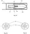
- FIGS. 6 a to 6 eeach show a cross sectional view of the mouthpiece end of a fifth embodiment of the smoking system.
- the smoking systemincludes guides for channelling the air flow within the smoking system. The air flow is shown by the dotted arrows.
- FIG. 6 ashows a first arrangement of the smoking system 600 .
- the guidesare provided by removable insert 601 and by the housing inside walls 603 .
- the removable insert 601extends only across the center of the smoking system 600 , thereby directing the air flow between the air inlet and the capillary wick and heating coil to the outer circumference of the device.
- the removable insert 601is shaped so that, at the capillary wick and heating coil, the air flow is directed onto the capillary wick and heating coil in a substantially radial direction, that is to say, substantially perpendicular to the longitudinal axis of the housing.
- the liquid cartridge, the capillary wick and the heating coilall form part of the removable insert 601 , although this need not be the case.
- housing inside walls 603provide guides for channelling the air and aerosol flow between the capillary wick and heating coil and the air outlet.
- the housing inside walls 603also define the aerosol forming chamber 602 .
- the housing inside walls 603are shaped so as to direct the air and aerosol flow substantially in the direction of the longitudinal axis of the housing.
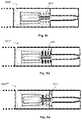
- FIG. 6 bshows a second arrangement of the smoking system 600 ′.
- the arrangement shown in FIG. 6 bis identical to that shown in FIG. 6 a except that an additional insert 605 is provided in the smoking system 600 ′ of FIG. 6 b .
- the additional insert 605provides additional guides for directing air flow.
- the insert 605is a ribbed insert surrounding the capillary wick and heating coil. It is shaped so as to direct the air flow onto the capillary wick and heating coil in a substantially radial direction, that is to say, substantially perpendicular to the longitudinal axis of the housing.
- FIG. 6 cshows a third arrangement of the smoking system 600 ′′.
- the arrangement shown in FIG. 6 cis identical to that shown in FIG. 6 a except that an additional insert 607 is provided in the smoking system 600 ′′ of FIG. 6 c .
- the additional insert 607provides additional guides for directing air flow.
- the insert 607is a grill insert including a tube having a number of longitudinally spaced holes.
- the insert 607surrounds the capillary wick and heating coil and directs the air flow through the holes in the grill and onto the capillary wick and heating coil in a substantially radial direction, that is to say, substantially perpendicular to the longitudinal axis of the housing.
- FIG. 6 dshows a fourth arrangement of the smoking system 600 ′′′.
- the arrangement shown in FIG. 6 dis identical to that shown in FIG. 6 a except that an additional insert 609 is provided in the smoking system 600 ′′′ of FIG. 6 d .
- the additional insert 609provides additional guides for directing air flow.
- the insert 609is a grooved insert including a solid cylindrical tube having a number of channels formed in the radial direction.
- the insert 609surrounds the capillary wick and heating coil and directs the air flow through the radial channels and onto the capillary wick and heating coil in a substantially radial direction, that is to say, substantially perpendicular to the longitudinal axis of the housing.
- FIG. 6 eshows a fifth arrangement of the smoking system 600 ′′′′.
- the arrangement shown in FIG. 6 eis identical to that shown in FIG. 6 a except that an additional insert 611 is provided in the smoking system 600 ′′′′ of FIG. 6 e .
- the additional insert 611provides additional guides for directing air flow.
- the insert 611is a grooved insert including a solid conical tube having a number of channels formed in the radial direction.
- the insert 611surrounds the capillary wick and heating coil and directs the air flow through the radial channels and onto the capillary wick and heating coil in a substantially radial direction, that is to say, substantially perpendicular to the longitudinal axis of the housing.
- the embodiments shown in FIG. 6 a to 6 eprovide a substantially radially directed air flow onto the capillary wick and heating coil and a substantially axially directed air and aerosol flow downstream of the capillary wick and heating coil. It has been found that managing air flow in this way improves the aerosol formation occurring within the smoking system.
- the guides provided by the insert 601 , and the additional insert 605 , 607 , 609 , 611 if present,channel the air flow as to direct the air flow onto the capillary wick and heating coil in a substantially radial direction. This provides the capillary wick and heating coil with cool, non-saturated air, which decreases the particle size of the aerosol inhaled by a user.
- the guides provided by the housing inside walls 603reduce the volume of the cavity in the smoking system and therefore improve aerosol flow towards the air outlet. This improves the smoking experience.
- the guides upstream of the capillary wick and heating coilmay be formed as one or more removable portions (inserts 601 , 605 , 607 , 609 and 611 , as shown) or alternatively as an integral part of the housing or as a combination of both.
- the guides downstream of the capillary wick and heating coilmay be formed as one or more removable portions or alternatively as an integral part of the housing (shaped housing inside walls 603 , as shown) or as a combination of both.
- the insert 601is shown without channels, although longitudinal channels towards the outside of the insert may be provided. In addition, if channels are provided, the insert may extend across the entire cross section of the housing. Any configuration of channels may be provided. The channels may be twisted around the axis of the housing, so as to encourage a swirled airflow.
- the channels in inserts 601 , 605 , 609 , 611 and the holes in insert 607may be formed by machining. Alternatively, the insert may be formed with channels or holes already formed, by injection molding. Any number of holes or channels may be formed in inserts 605 , 607 , 609 , 611 .
- the insert 601includes a locating pin or protrusion (not shown) on its outer surface for cooperating with a recess (also not shown) on the inside of the housing walls, so as to ensure that the insert is correctly positioned within the smoking system. This may be important for the electrical connections to the heating coil, for example.
- the inserts 605 , 607 , 609 , 611may also be provided with such a locating pin or protrusion.
- the housing inside walls 603may be shaped appropriately for the desired volume and shape of the aerosol forming chamber within the smoking system.
- FIGS. 7 a to 7 cshow a sixth embodiment of the smoking system.
- FIG. 7 ashows a cross sectional view of the mouthpiece end of the sixth embodiment of the smoking system 700 .
- the smoking system 700includes guides for channelling the air flow within the smoking system.
- the guidesare provided by removable insert 701 and by the housing walls 703 .
- the air flowis shown by the dotted arrows.
- the removable insert 701is similar to removable insert 601 shown in FIGS. 6 a to 6 e and extends only across the center of the smoking system 700 , thereby directing the air flow between the air inlet and the capillary wick and heating coil to the outer circumference of the device.
- the liquid cartridge, the capillary wick and the heating coilall form part of the removable insert 701 , although this need not be the case.
- housing inside walls 703provide guides for channelling the aerosol flow onto the capillary wick and heating coil, and between the capillary wick and heating coil and the air outlet.
- the housing inside walls 703also define the aerosol forming chamber 702 .
- the housing walls 703are shaped so that the incoming air flow onto the capillary wick and heating coil is directed in an upstream channel 705 tangential to the circular cross section of the device and the circular cross section of the aerosol forming chamber 702 .
- FIG. 7 bis a cross section along line D-D of FIG. 7 a .
- the housing inside walls 703are shaped so that the channel 705 provides an air flow towards the capillary wick and heating coil that is in the tangential direction. This produces a spiralling air flow around the capillary wick and heating coil towards the air outlet.
- FIG. 7 cis a cross section also along line D-D showing an alternative arrangement, in which two channels 705 , 705 ′ towards the capillary wick and heating coil are provided. Both channels direct the air flow in a tangential direction and together they produce a spiralling air flow around the capillary wick and heating coil towards the air outlet. Additional tangential upstream channels could also be provided.
- FIGS. 7 a , 7 b and 7 cprovides a substantially tangentially directed air flow onto the capillary wick and heating coil and a substantially spiralling air flow around the capillary wick and heating coil and from the capillary wick and heating coil to the air outlet. It has been found that managing the air flow in this way improves the aerosol formation occurring within the smoking system.
- the shaped inside walls 703 of the housing, together with the insert 701direct the air flow so as to supply cool and non-saturated air to the capillary wick and heating coil. Once air flow targets the capillary wick and heating coil, it is immediately evacuated towards the air outlet. This decreases the particle size of the aerosol inhaled by a user.
- the spiralling air flow around the capillary wick and heating coilincreases turbulence and reduces aerosol particle size.
- the size of the tangential channel or channels and its position relative to the longitudinal axis of the deviceinfluence the air flow around the capillary wick and heating coil and therefore the aerosol characteristics.
- the centrifugal forces in the spiralling air flowmay allow larger aerosol particles to impact and be trapped on the outer walls of the aerosol forming chamber 702 . This is shown schematically in FIG. 7 a .
- the arrangement of FIG. 7 cfurther improves aerosol formation by providing a better flow distribution within the aerosol forming chamber.
- the cross section of the deviceis preferably circular, so that the channel 705 can define a tangential air flow.
- Other cross sectional shapesare also possible, as long as some sort of upstream tangential channel can be defined.
- More than one air inlet (in the housing)may be provided.
- the guides upstream of the capillary wick and heating coilmay be formed as one or more removable portions or alternatively as an integral part of the housing or as a combination of both (removable insert 701 combined with shaped housing walls 703 , as shown).
- the guides downstream of the capillary wick and heating coilmay be formed as one or more removable portions or alternatively as an integral part of the housing (shaped housing inside walls 703 , as shown) or as a combination of both.
- the insert 701is shown without channels, although longitudinal channels towards the outside of the insert 701 may be provided. In addition, if channels are provided, the insert may extend across the entire cross section of the housing. Any configuration of channels may be provided. The channels may be twisted around the axis of the housing, so as to encourage a swirled airflow. Any channels in insert 701 may be formed by machining. Alternatively, the insert may be formed with channels or holes already formed, by injection molding.
- the insert 701may include a locating pin or protrusion (not shown) on its outer surface for cooperating with a recess (also not shown) on the inside of the housing walls, so as to ensure that the insert is correctly positioned within the smoking system. This may be important for the electrical connections to the heating coil, for example.
- the housing inside walls 703may be shaped appropriately for the desired volume and shape of the aerosol forming chamber within the smoking system. This affects the spiralling aerosol flow around the capillary wick and heating coil and therefore the aerosol characteristics.
- the tangential channels 705 , 705 ′may be positioned at any height along the capillary wick and may have any suitable cross section.
- FIGS. 8 a to 8 cshow a seventh embodiment of the smoking system.
- FIG. 8 ashows a cross sectional view of the mouthpiece end of the seventh embodiment of the smoking system 800 .
- the smoking system 800includes guides for channelling the air flow within the smoking system.
- the guidesare provided by removable insert 801 , in the shaped housing walls 803 and by impactor 807 .
- the air flowis shown by the dotted arrows.
- the removable insert 801is similar to removable insert 601 shown in FIGS. 6 a to 6 e and removable insert 701 shown in FIG. 7 a and extends only across the center of the smoking system 800 , thereby directing the air flow between the air inlet and the capillary wick and heating coil to the outer circumference of the device.
- the liquid cartridge, the capillary wick and the heating coilall form part of the removable insert 801 , although this need not be the case.
- housing inside walls 803provide guides for channelling the air flow onto the capillary wick and heating coil.
- the housing walls 803are shaped so that the incoming air flow onto the capillary wick and heating coil is directed through an upstream channel 805 tangential to the circular cross section of the device and the circular cross section of the aerosol forming chamber 802 .
- an impactor 807is provided at the downstream end of the capillary wick and heating coil.
- the impactorprovides guides for channelling the air flow away from the capillary wick and heating coil and towards the air outlet.
- the impactor 807in conjunction with the housing inside walls, also defines the aerosol forming chamber 802 .
- the air flowis directed away from the capillary wick and heating coil in the radial direction in downstream channels 809 , that is to say, substantially perpendicular to the longitudinal axis of the housing.
- the impactor 807allows larger aerosol particles to be trapped on its upstream side. This is shown schematically in FIG. 8 a .
- the housing inside walls 803may be tapered to direct the air flow towards the air outlet, although this is not shown in FIG. 8 a.
- FIG. 8 bis a cross section along line E-E of FIG. 8 a showing the upstream channel 805 .
- the housing walls 803are shaped so that the channel 805 provides an air flow towards the capillary wick and heating coil that is in the tangential direction. This produces a spiralling air flow around the capillary wick and heating coil.
- FIG. 8 cis a cross section along line F-F of FIG. 8 a showing the downstream channels 809 .
- the impactor 807 and housing walls 803cooperate so that the channels 809 provide an air flow away from the capillary wick and heating coil that is in substantially the radial direction. That is to say, downstream of the spiralling air flow around the capillary wick and heating coil, the aerosol flow is directed in the radial direction and then towards the air outlet.
- FIGS. 8 a , 8 b and 8 cprovides a substantially tangentially directed air flow onto the capillary wick and heating coil, a substantially spiralling air flow around the capillary wick and heating coil and a substantially radially directed air flow away from the capillary wick and heating coil to the air outlet. It has been found that managing the air flow in this way improves the aerosol formation occurring within the smoking system.
- the shaped inside walls 803 of the housing, together with the insert 801direct the air flow so as to supply cool and non-saturated air to the capillary wick and heating coil. This decreases the particle size of the aerosol inhaled by a user.
- the spiralling air flow around the capillary wick and heating coilincreases turbulence and reduces aerosol particle size. Larger aerosol particles may also become trapped on the inside walls of the aerosol forming chamber 802 due to centrifugal forces. This is shown schematically in FIG. 8 a .
- the radially directed outgoing air flowmeans that once air flow targets the capillary wick and heating coil, it is immediately evacuated towards the air outlet. Additional upstream tangential channels may be provided (as in FIG. 7 c for example) which may provide a better flow distribution within the aerosol forming chamber.
- the size of the tangential channel or channels and its position relative to the longitudinal axis of the deviceinfluence the air flow around the capillary wick and heating coil and therefore the aerosol characteristics.
- the impactormay allow larger aerosol particles to impact on its upstream wall. This is shown schematically in FIG. 8 a.
- the cross section of the deviceis preferably circular, so that the channel 805 can define a tangential air flow.
- Other cross sectional shapesare also possible, as long as an upstream tangential channel can be defined.
- More than one air inlet (in the housing)may be provided.
- the guides upstream of the capillary wick and heating coilmay be formed as one or more removable portions or alternatively as an integral part of the housing or as a combination of both (removable insert 801 combined with shaped housing walls 803 , as shown).
- the guides downstream of the capillary wick and heating coilmay be formed as one or more removable portions or alternatively as an integral part of the housing or as a combination of both (shaped housing inside walls 803 combined with impactor 807 , as shown).
- the insert 801is shown without channels, although longitudinal channels towards the outside of the insert 801 may be provided.
- the insertmay extend across the entire cross section of the housing. Any configuration of channels may be provided. The channels may be twisted around the axis of the housing, so as to encourage a swirled airflow. Any channels in insert 801 may be formed by machining. Alternatively, the insert may be formed with channels or holes already formed, by injection molding. The insert 801 may include a locating pin or protrusion (not shown) on its outer surface for cooperating with a recess (also not shown) on the inside of the housing walls, so as to ensure that the insert is correctly positioned within the smoking system. This is important for the electrical connections to the heating coil, for example.
- the housing inside walls 803may be shaped appropriately for the desired volume and shape of the aerosol forming chamber within the smoking system. This affects the spiralling aerosol flow around the capillary wick and heating coil and therefore the aerosol characteristics.
- the tangential channel 805may be positioned at any height along the capillary wick and may have any suitable cross section. Any number of radial channels 809 may be provided.
- the impactor 807may be formed with any appropriate shape and is preferably designed in conjunction with the shaped housing inside walls 803 , in order to channel the air flow as desired.
- FIGS. 9 a to 9 dshow an eighth embodiment of the smoking system.
- FIG. 9 ashows a cross sectional view of the mouthpiece end of the eighth embodiment of the smoking system 900 .
- the smoking system 900includes guides for channelling the air flow within the smoking system.
- the guidesare provided in removable insert 901 and in the shaped housing walls 903 .
- the air flowis shown by the dotted arrows.
- the removable insert 901is similar to removable inserts 601 , 701 and 801 and extends only across the center of the smoking system 900 , thereby directing the air flow between the air inlet and the capillary wick and heating coil to the outer circumference of the housing.
- the liquid cartridge, the capillary wick and the heating coilall form part of the removable insert 901 , although this need not be the case.
- the housing inside walls 903provide guides for channelling the aerosol flow onto the capillary wick and heating coil and off the capillary wick and heating coil.
- the housing walls 903are shaped so that the incoming air flow onto the capillary wick and heating coil is directed through an upstream channel 905 tangential to the circular cross section of the housing and the circular cross section of the aerosol forming chamber 902 .
- the housing walls 903are shaped so that the outgoing air flow off the capillary wick and heating coil is directed through an downstream channel 907 also tangential to the circular cross section of the housing and the circular cross section of the aerosol forming chamber 902 .
- the housing walls 903are shaped to provide an impactor surface 909 downstream of the capillary wick and heating coil.
- the impactor surface 909may allow larger aerosol particles to be trapped. This is shown schematically in FIG. 9 a .
- the housing inside wallsalso define the aerosol forming chamber 902 .
- the housing inside walls 903may be tapered to direct the air flow towards the air outlet, although this is not shown in FIG. 9 a.
- FIG. 9 bis a cross section along line G-G of FIG. 9 a showing the upstream channel 905 .
- the housing walls 903are shaped so that the channel 905 provides an air flow towards the capillary wick and heating coil that is in the tangential direction. This produces a spiralling air flow around the capillary wick and heating coil.
- FIG. 9 cis a cross section along line H-H of FIG. 9 a showing the downstream channel 907 .
- the housing walls 903are shaped so that the channel 907 provides an air flow away from the capillary wick and heating coil that is in the tangential direction. That is to say, after the air has spiralled around the capillary wick and heating coil, it is directed in the tangential direction and then towards the air outlet.
- FIG. 9 dshows an alternative cross section along line H-H of FIG. 9 a , also showing downstream channel 907 ′.
- the channel 907is on the same side of the device as the channel 905 .
- the channel 907 ′is on the opposite side of the device as the channel 905 .
- FIGS. 9 a , 9 b , 9 c and 9 dprovides a substantially tangentially directed air flow onto the capillary wick and heating coil, a substantially spiralling air flow around the capillary wick and heating coil and a substantially tangentially directed air flow off the capillary wick and heating coil and then to the air outlet. It has been found that managing the air flow in this way improves the aerosol formation occurring within the smoking system.
- the shaped inside walls 903 of the housing, together with the insert 901direct the air flow so as to supply cool and non-saturated air to the capillary wick and heating coil. This decreases the particle size of the aerosol inhaled by a user.
- the spiralling air flow around the capillary wick and heating coilincreases turbulence and reduces aerosol particle size. Larger aerosol particles may also become trapped on the inside walls of the aerosol forming chamber 902 due to centrifugal forces. This is shown schematically in FIG. 9 a .
- the tangentially directed outgoing air flowmeans that once air flow has circled the capillary wick and heating coil, it is immediately evacuated towards the air outlet.
- Additional upstream or downstream tangential channelsmay be provided which may provide a better flow distribution within the aerosol forming chamber.
- the size of the tangential channels and their position relative to the longitudinal axis of the deviceinfluence the air flow around the capillary wick and heating coil and therefore the aerosol characteristics.
- the cross section of the deviceis preferably circular, so that the channels 905 and 907 can define a tangential air flow. However, other cross sectional shapes are also possible as long as tangential channels can be defined. More than one air inlet (in the housing) may be provided.
- the guides upstream of the capillary wick and heating coilmay be formed as one or more removable portions or alternatively as an integral part of the housing or as a combination of both (removable insert 901 combined with shaped housing walls 903 , as shown).
- the guides downstream of the capillary wick and heating coilmay be formed as one or more removable portions or alternatively as an integral part of the housing (shaped housing walls 903 , as shown) or as a combination of both.
- the insert 901is shown without channels, although longitudinal channels towards the outside of the insert 901 may be provided.
- the insertmay extend across the entire cross section of the housing. Any configuration of channels may be provided. The channels may be twisted around the axis of the housing, so as to encourage a swirled airflow. Any channels in insert 901 may be formed by machining. Alternatively, the insert may be formed with channels or holes already formed, by injection molding.
- the insert 901may include a locating pin or protrusion (not shown) on its outer surface for cooperating with a recess (also not shown) on the inside of the housing walls, so as to ensure that the insert is correctly positioned within the smoking system. This is important for the electrical connections to the heating coil, for example.
- the housing inside walls 903may be shaped appropriately for the desired volume and shape of the aerosol forming chamber within the smoking system. This affects the spiralling aerosol flow around the capillary wick and heating coil and therefore the aerosol characteristics.
- the tangential channels 905 , 907may be positioned at any height along the capillary wick and may have any suitable cross section. Any number of tangential upstream and downstream channels may be provided.
- FIGS. 10 a to 10 dshow a ninth embodiment of the smoking system.
- FIG. 10 ashows a cross sectional view of the smoking system including removable insert 1001 .
- FIG. 10 bis a cross section along line B-B of FIG. 10 a , showing the mouthpiece end only.
- FIG. 10 cis a cross section along line C-C of FIG. 10 a , showing the mouthpiece end only.
- the smoking system 1000includes guides for channelling the air flow within the smoking system. The air flow is shown by the dotted arrows.
- the removable insert 1001is shown in cross section in FIG. 10 a .
- the insertincludes upstream channels 1003 for channelling the air flow from the air inlet onto the capillary wick and heating coil and downstream channels 1005 for channelling the air flow away from the capillary wick and heating coil towards the air outlet.
- the channels 1003 and 1005are substantially perpendicular to one another and also substantially perpendicular to the longitudinal axis of the housing.
- FIG. 10 bshows a cross section along B-B of FIG. 10 a
- FIG. 10 cshows a cross section along C-C of FIG. 10 a
- the guidesare provided by removable insert 1001 and removable insert 1007 .
- the removable insert 1007is similar to removable inserts 601 , 701 , 801 and 901 and extends only across the center of the smoking system 1000 , thereby directing the air flow between the air inlet and the capillary wick and heating coil to the outer circumference of the housing.
- FIGS. 10 bshows a cross section along B-B of FIG. 10 a
- FIG. 10 cshows a cross section along C-C of FIG. 10 a
- the guidesare provided by removable insert 1001 and removable insert 1007 .
- the removable insert 1007is similar to removable inserts 601 , 701 , 801 and 901 and extends only across the center of the smoking system 1000 , thereby directing the air flow between the air inlet and the capillary wick and
- the liquid cartridge, the capillary wick and the heating coilall form part of the removable insert 1007 , although this need not be the case.
- the removable insert 1001is positioned around the capillary wick and heating coil. The removable insert 1001 extends across the entire cross section of the device.
- FIG. 10 bshows a cross section along B-B of FIG. 10 a
- FIG. 10 bshows the air flow upstream of the capillary wick and heating coil.
- the channels 1003direct the air flow onto the capillary wick and heating coil in a substantially radial direction, that is to say, substantially perpendicular to the longitudinal axis of the housing.
- FIG. 10 cshows a cross section along C-C of FIG. 10 a
- FIG. 10 cshows the air flow downstream of the capillary wick and heating coil.
- the channels 1005direct the air flow away from the capillary wick and heating coil in a substantially radial direction.
- the channels 1005define the aerosol forming chamber 1002 .
- the housing wallsmay additionally be tapered towards the air outlet, although this is not shown in FIGS. 10 b and 10 c.
- FIG. 10 dshows an alternative arrangement for the removable insert 1001 ′.
- the insertincludes four upstream channels 1003 ′ for channelling the air flow from the air inlet onto the capillary wick and heating coil.
- the insertalso includes two downstream channels 1005 ′ for channelling the air flow away from the capillary wick and heating coil towards the air outlet.
- the channels 1003 ′ and 1005 ′are substantially perpendicular to the longitudinal axis of the housing. The channels are directed in the radial direction.
- two upstream channels 1003are shown in FIG. 10 a and four upstream channels 1003 ′ are shown in FIG.
- any suitable number of upstream channelsmay be provided, all in the radial direction and substantially perpendicular to the longitudinal axis of the housing.
- two downstream channels 1005 , 1005 ′are shown in FIGS. 10 a and 10 d , any suitable number of downstream channels may be provided, all in the radial direction and substantially perpendicular to the longitudinal axis of the housing.
- FIGS. 10 a to 10 dprovide a substantially radially directed air flow onto the capillary wick and heating coil and a substantially radially directed air flow off the capillary wick and heating coil. It has been found that managing air flow in this way improves the aerosol formation occurring within the smoking system.
- the guides provided by the inserts 1007 and 1001channel the air flow as to direct the air flow onto the capillary wick and heating coil in a substantially radial direction. This provides the capillary wick and heating coil with cool, non-saturated air, which decreases the particle size of the aerosol inhaled by a user.
- the guides provided by the insert 1001channel the air flow as to direct the air flow off the capillary wick and heating coil in a substantially radial direction and also reduce the volume of the aerosol forming chamber 1002 in the smoking system. This improves aerosol flow towards the air outlet. This improves the smoking experience.
- the guides upstream of the capillary wick and heating coilmay be formed as one or more removable portions (inserts 1001 and 1007 , as shown) or alternatively as an integral part of the housing or as a combination of both.
- the guides downstream of the capillary wick and heating coilmay be formed as one or more removable portions (insert 1001 , as shown) or alternatively as an integral part of the housing or as a combination of both.
- the insert 1007is shown without channels, although longitudinal channels towards the outside of the insert may be provided.
- the insertmay extend across the entire cross section of the housing. Any configuration of channels may be provided.
- the channelsmay be twisted around the axis of the housing, so as to encourage a swirled airflow.
- the channels in insert 1007may be formed by machining.
- the insertmay be formed with channels or holes already formed, by injection molding.
- the insert 1007includes a locating pin or protrusion (not shown) on its outer surface for cooperating with a recess (also not shown) on the inside of the housing walls, so as to ensure that the insert is correctly positioned within the smoking system. This is important for the electrical connections to the heating coil, for example.
- the channelsmay be evenly or non-evenly distributed circumferentially around the insert.
- the channelsmay have a constant cross sectional shape and area along their length, or the cross sectional shape can vary along the length.
- the channelsmay include some channels having different cross sectional shapes and areas from others.
- the channels in insert 1001may be formed by machining.
- the insertmay be formed with channels or holes already formed, by injection molding.
- the insert 1001includes a locating pin or protrusion (not shown) on its outer surface for cooperating with a recess (also not shown) on the inside of the housing walls, so as to ensure that the insert is correctly positioned within the smoking system. This is important for the electrical connections to the heating coil, for example.
- the channels 1005may be shaped appropriately for the desired volume and shape of the aerosol forming chamber within the smoking system.
- FIGS. 11 a to 11 nshow a tenth embodiment of the smoking system.
- the smoking systemincludes guides for channelling the air flow within the smoking system. The air flow is shown by the dotted arrows.
- FIG. 11 ashows a first arrangement of the smoking system 1100
- FIG. 11 bis a cross section along line J-J of FIG. 11 a
- the guidesare provided by removable insert 1101 , second removable insert 1103 and by the shaped housing inside walls 1105 .
- the removable insert 1101extends only across the center of the smoking system 1100 , thereby directing the air flow between the air inlet and the capillary wick and heating coil to the outer circumference of the housing.
- the liquid cartridge, the capillary wick and the heating coilall form part of the removable insert 1101 , although this need not be the case.
- the second removable insert 1103is shaped so that the air flow is directed across the capillary wick and heating coil in a substantially perpendicular direction. That is to say, the air flow is substantially perpendicular to the longitudinal axis of the housing and to the capillary wick.
- the second removable insert 1103provides an upstream channel 1107 on one side of the insert and an downstream channel 1109 on the other side of the insert. When the insert is positioned around the capillary wick and heating coil, the air therefore flows directly across the capillary wick and heating coil.
- the insert 1103also defines the aerosol forming chamber 1102 .
- housing inside walls 1005provide guides for channelling the air and aerosol flow between the capillary wick and heating coil and the air outlet.
- the housing inside walls 1105are tapered towards the air outlet so as to direct the air and aerosol flow towards the air outlet.
- FIG. 11 cshows a second arrangement of the smoking system 1100 ′ and FIG. 11 d is a cross section along line K-K of FIG. 11 c .
- the arrangement shown in FIGS. 11 c and 11 dis identical to that shown in FIGS. 11 a and 11 b except that second removable insert 1103 includes a perturbator 1111 surrounding the capillary wick and heating coil.
- the perturbator 1111includes a cylindrical tube surrounding the capillary wick and heating coil, with holes to direct the air flow onto and away from the capillary wick and heating coil. This provides additional turbulence in the aerosol forming chamber 1102 .
- FIG. 11 eshows another embodiment of removable insert 1103 ′.
- the embodiment shown in FIG. 11 eis identical to that shown in FIG. 11 b except that the aerosol forming chamber is formed with restrictions 1117 towards the downstream side.
- the restrictions 1117provide turbulence and, in particular, allow the air flow to strike the downstream side of the capillary wick and heating coil.
- FIG. 11 fif shows another embodiment of removable insert 1103 ′′.
- the embodiment shown in FIG. 11 fprovides two upstream channels 1107 a and 1107 b on opposite sides of the insert and two downstream channels 1109 a and 1109 b on opposite sides of the insert. Air flow is directed from upstream channel 1107 a , directly across the capillary wick and heating coil, towards downstream channel 1109 b . At the same time, air flow is directed in the opposite direction from upstream channel 1107 b , directly across the capillary wick and heating coil, towards downstream channel 1109 a . This provides additional turbulence.
- the aerosol forming chamberis formed with divisions 1119 .
- the aerosol forming chamberis formed with restrictions 1117 ′ towards each downstream side, although the restrictions 1117 ′ may be omitted.
- the restrictions 1117 ′provide turbulence and, in particular, allow the air flow to strike the downstream side of the capillary wick and heating coil.
- FIG. 11 gshows another arrangement of the smoking system.
- FIG. 11 gis a cross section, similar to the cross sections in FIGS. 11 b , 11 d , 11 e and 11 f , but showing the FIG. 11 g arrangement.
- two pins 1119 , 1121are provided in the air flow across the capillary wick and heating coil. The pins direct the air flow and provide further turbulence in the aerosol forming chamber.
- the pinsare the connection pins for the heating coil, pin 1119 being the positive connection, pin 1121 being the negative connection. However, this need not be the case.
- FIG. 11 ishows an alternative version for the arrangement shown in FIG. 11 g .
- the pins 1119 ′, 1121 ′are formed as flags.
- Pin 1119 ′has a pin portion 1119 a at its base and a wider blade portion 1119 b at its upper part.
- pin 1121 ′has a pin portion 1121 a at its base and a wider blade portion 1121 b at its upper part. This provides better direction of the air flow across the capillary wick and heating coil.
- FIG. 11 jshows another alternative version for the arrangement shown in FIG. 11 g .
- the pinsare formed as wide heating blades 1119 ′′, 1121 ′′. Again, this provides better direction of the air flow across the capillary wick and heating coil.
- FIGS. 11 k and 11 lshow two alternative arrangements for the pins shown in FIGS. 11 i and 11 j .
- FIG. 11 kis a cross section, similar to the cross sections in FIGS. 11 b , 11 d , 11 e , 11 f and 11 h .
- the blade portions of the pinsmay be straight and directed in the downstream direction, that is to say, towards the downstream channel 1109 .
- FIG. 11 lis a cross section, similar to the cross sections in FIGS. 11 b , 11 d , 11 e , 11 f , 11 h and 11 k .
- the blade portions of the pinsmay be curved and directed in the downstream direction, that is to say, towards the downstream channel 1109 .
- FIGS. 11 a to 11 lprovide a substantially radially directed air flow onto the capillary wick and heating coil and a substantially radially directed air flow off the capillary wick and heating coil.
- the air flowis directed across the capillary wick and heating coil. It has been found that managing air flow in this way improves the aerosol formation occurring within the smoking system.
- the guides provided by the inserts 1101 and 1103channel the air flow as to direct the air flow onto the capillary wick and heating coil in a substantially radial direction. This provides the capillary wick and heating coil with cool, non-saturated air, which decreases the particle size of the aerosol inhaled by a user.
- the guides provided by the insert 1103channel the air flow as to direct the air flow off the capillary wick and heating coil in a substantially radial direction and also reduce the volume of the aerosol forming chamber in the smoking system. This improves aerosol flow towards the air outlet.
- additional componentsmay be provided to increase turbulence. This improves the smoking experience.
- the guides upstream of the capillary wick and heating coilmay be formed as one or more removable portions (inserts 1101 and 1103 , as shown) or alternatively as an integral part of the housing or as a combination of both.
- the guides downstream of the capillary wick and heating coilmay be formed as one or more removable portions or alternatively as an integral part of the housing or as a combination of both (insert 1103 and shaped housing walls 1105 , as shown).
- the insert 1101is shown without channels, although longitudinal channels towards the outside of the insert may be provided. In addition, if channels are provided, the insert may extend across the entire cross section of the housing. Any configuration of channels may be provided. The channels may be twisted around the axis of the housing, so as to encourage a swirled airflow.
- the channels in insert 1101may be formed by machining. Alternatively, the insert may be formed with channels or holes already formed, by injection molding.
- the insert 1101includes a locating pin or protrusion (not shown) on its outer surface for cooperating with a recess (also not shown) on the inside of the housing walls, so as to ensure that the insert is correctly positioned within the smoking system. This may be important for the electrical connections to the heating coil, for example.
- any suitable configuration of channelsmay be provided in insert 1103 including any suitable number of upstream channels and any suitable number of downstream channels.
- the channelsmay have a constant cross sectional shape and area along their length, or the cross sectional shape can vary along the length.
- the channelsmay include some channels having different cross sectional shapes and areas from others.
- the channels in insert 1103may be formed by machining.
- the insertmay be formed with channels or holes already formed, by injection molding.
- the insert 1103includes a locating pin or protrusion (not shown) on its outer surface for cooperating with a recess (also not shown) on the inside of the housing walls, so as to ensure that the insert is correctly positioned within the smoking system.
- the insert 1103may be shaped appropriately for the desired volume of the aerosol forming chamber within the smoking system.
- the pins shown in FIGS. 11 g to 11 lmay have suitable shape in order to direct the air flow across the capillary wick and heating element as desired.
- the pinsare shown as the connections to the heating coil, this need not be the case.
Landscapes
- Health & Medical Sciences (AREA)
- Engineering & Computer Science (AREA)
- Life Sciences & Earth Sciences (AREA)
- Animal Behavior & Ethology (AREA)
- Anesthesiology (AREA)
- Biomedical Technology (AREA)
- Heart & Thoracic Surgery (AREA)
- Hematology (AREA)
- Veterinary Medicine (AREA)
- Public Health (AREA)
- General Health & Medical Sciences (AREA)
- Pulmonology (AREA)
- Bioinformatics & Cheminformatics (AREA)
- Chemical & Material Sciences (AREA)
- Chemical Kinetics & Catalysis (AREA)
- General Chemical & Material Sciences (AREA)
- Catching Or Destruction (AREA)
- Medicinal Preparation (AREA)
Abstract
Description
Claims (14)
Priority Applications (3)
| Application Number | Priority Date | Filing Date | Title |
|---|---|---|---|
| US15/220,927US11013265B2 (en) | 2009-10-27 | 2016-07-27 | Smoking system having a liquid storage portion |
| US16/915,185US12059524B2 (en) | 2009-10-27 | 2020-06-29 | Smoking system having a liquid storage portion |
| US18/745,415US20240335626A1 (en) | 2009-10-27 | 2024-06-17 | Smoking system having a liquid storage portion |
Applications Claiming Priority (5)
| Application Number | Priority Date | Filing Date | Title |
|---|---|---|---|
| EP09252490.9 | 2009-10-27 | ||
| EP09252490AEP2319334A1 (en) | 2009-10-27 | 2009-10-27 | A smoking system having a liquid storage portion |
| EP09252490 | 2009-10-27 | ||
| US12/913,510US9420829B2 (en) | 2009-10-27 | 2010-10-27 | Smoking system having a liquid storage portion |
| US15/220,927US11013265B2 (en) | 2009-10-27 | 2016-07-27 | Smoking system having a liquid storage portion |
Related Parent Applications (1)
| Application Number | Title | Priority Date | Filing Date |
|---|---|---|---|
| US12/913,510ContinuationUS9420829B2 (en) | 2009-10-27 | 2010-10-27 | Smoking system having a liquid storage portion |
Related Child Applications (1)
| Application Number | Title | Priority Date | Filing Date |
|---|---|---|---|
| US16/915,185ContinuationUS12059524B2 (en) | 2009-10-27 | 2020-06-29 | Smoking system having a liquid storage portion |
Publications (2)
| Publication Number | Publication Date |
|---|---|
| US20160331039A1 US20160331039A1 (en) | 2016-11-17 |
| US11013265B2true US11013265B2 (en) | 2021-05-25 |
Family
ID=41694577
Family Applications (5)
| Application Number | Title | Priority Date | Filing Date |
|---|---|---|---|
| US12/913,510Active2033-05-14US9420829B2 (en) | 2009-10-27 | 2010-10-27 | Smoking system having a liquid storage portion |
| US15/077,226Active2032-05-01US10485266B2 (en) | 2009-10-27 | 2016-03-22 | Smoking system having a liquid storage portion |
| US15/220,927Active2032-09-19US11013265B2 (en) | 2009-10-27 | 2016-07-27 | Smoking system having a liquid storage portion |
| US16/915,185Active2033-07-08US12059524B2 (en) | 2009-10-27 | 2020-06-29 | Smoking system having a liquid storage portion |
| US18/745,415PendingUS20240335626A1 (en) | 2009-10-27 | 2024-06-17 | Smoking system having a liquid storage portion |
Family Applications Before (2)
| Application Number | Title | Priority Date | Filing Date |
|---|---|---|---|
| US12/913,510Active2033-05-14US9420829B2 (en) | 2009-10-27 | 2010-10-27 | Smoking system having a liquid storage portion |
| US15/077,226Active2032-05-01US10485266B2 (en) | 2009-10-27 | 2016-03-22 | Smoking system having a liquid storage portion |
Family Applications After (2)
| Application Number | Title | Priority Date | Filing Date |
|---|---|---|---|
| US16/915,185Active2033-07-08US12059524B2 (en) | 2009-10-27 | 2020-06-29 | Smoking system having a liquid storage portion |
| US18/745,415PendingUS20240335626A1 (en) | 2009-10-27 | 2024-06-17 | Smoking system having a liquid storage portion |
Country Status (26)
| Country | Link |
|---|---|
| US (5) | US9420829B2 (en) |
| EP (6) | EP2319334A1 (en) |
| JP (1) | JP5901527B2 (en) |
| KR (7) | KR20170134770A (en) |
| CN (2) | CN105815814B (en) |
| AU (1) | AU2010311893B2 (en) |
| BR (1) | BR112012010034B1 (en) |
| CA (1) | CA2778786C (en) |
| CO (1) | CO6551748A2 (en) |
| DK (2) | DK2493341T3 (en) |
| EA (3) | EA023124B1 (en) |
| ES (4) | ES2856895T3 (en) |
| HU (3) | HUE053178T2 (en) |
| IL (1) | IL219338A (en) |
| LT (1) | LT2606756T (en) |
| MX (1) | MX2012005034A (en) |
| MY (1) | MY183178A (en) |
| NZ (1) | NZ599821A (en) |
| PH (1) | PH12012500813A1 (en) |
| PL (4) | PL2606756T5 (en) |
| PT (2) | PT2606756T (en) |
| RS (2) | RS52925B (en) |
| SI (1) | SI2606756T2 (en) |
| UA (1) | UA106393C2 (en) |
| WO (1) | WO2011050943A1 (en) |
| ZA (1) | ZA201202994B (en) |
Cited By (2)
| Publication number | Priority date | Publication date | Assignee | Title |
|---|---|---|---|---|
| US12133558B2 (en) | 2017-02-08 | 2024-11-05 | Japan Tobacco Inc. | Cartridge having partition member and heater and inhaler including same |
| US12171264B2 (en) | 2017-05-18 | 2024-12-24 | Jt International S.A. | Vaporizer unit having a heating element with an electrically conductive cover or coating |
Families Citing this family (574)
| Publication number | Priority date | Publication date | Assignee | Title |
|---|---|---|---|---|
| US9675109B2 (en) | 2005-07-19 | 2017-06-13 | J. T. International Sa | Method and system for vaporization of a substance |
| US11647783B2 (en) | 2005-07-19 | 2023-05-16 | Juul Labs, Inc. | Devices for vaporization of a substance |
| US20160345631A1 (en) | 2005-07-19 | 2016-12-01 | James Monsees | Portable devices for generating an inhalable vapor |
| US7726320B2 (en) | 2006-10-18 | 2010-06-01 | R. J. Reynolds Tobacco Company | Tobacco-containing smoking article |
| US8991402B2 (en) | 2007-12-18 | 2015-03-31 | Pax Labs, Inc. | Aerosol devices and methods for inhaling a substance and uses thereof |
| EP2110034A1 (en)* | 2008-04-17 | 2009-10-21 | Philip Morris Products S.A. | An electrically heated smoking system |
| EP2113178A1 (en)* | 2008-04-30 | 2009-11-04 | Philip Morris Products S.A. | An electrically heated smoking system having a liquid storage portion |
| AT507187B1 (en) | 2008-10-23 | 2010-03-15 | Helmut Dr Buchberger | INHALER |
| EP2253233A1 (en) | 2009-05-21 | 2010-11-24 | Philip Morris Products S.A. | An electrically heated smoking system |
| EP2319334A1 (en) | 2009-10-27 | 2011-05-11 | Philip Morris Products S.A. | A smoking system having a liquid storage portion |
| EP2327318A1 (en) | 2009-11-27 | 2011-06-01 | Philip Morris Products S.A. | An electrically heated smoking system with internal or external heater |
| US9259035B2 (en) | 2010-05-15 | 2016-02-16 | R. J. Reynolds Tobacco Company | Solderless personal vaporizing inhaler |
| US10159278B2 (en) | 2010-05-15 | 2018-12-25 | Rai Strategic Holdings, Inc. | Assembly directed airflow |
| US9743691B2 (en) | 2010-05-15 | 2017-08-29 | Rai Strategic Holdings, Inc. | Vaporizer configuration, control, and reporting |
| US9861772B2 (en) | 2010-05-15 | 2018-01-09 | Rai Strategic Holdings, Inc. | Personal vaporizing inhaler cartridge |
| US9999250B2 (en) | 2010-05-15 | 2018-06-19 | Rai Strategic Holdings, Inc. | Vaporizer related systems, methods, and apparatus |
| US9095175B2 (en) | 2010-05-15 | 2015-08-04 | R. J. Reynolds Tobacco Company | Data logging personal vaporizing inhaler |
| US10136672B2 (en) | 2010-05-15 | 2018-11-27 | Rai Strategic Holdings, Inc. | Solderless directly written heating elements |
| US11344683B2 (en) | 2010-05-15 | 2022-05-31 | Rai Strategic Holdings, Inc. | Vaporizer related systems, methods, and apparatus |
| US8757147B2 (en) | 2010-05-15 | 2014-06-24 | Minusa Holdings Llc | Personal vaporizing inhaler with internal light source |
| CN201830900U (en)* | 2010-06-09 | 2011-05-18 | 李永海 | Tobacco juice atomization device for electronic cigarette |
| SMT202000393T1 (en) | 2010-08-24 | 2020-09-10 | Jt Int Sa | Inhalation device including substance usage controls |
| AT510837B1 (en) | 2011-07-27 | 2012-07-15 | Helmut Dr Buchberger | INHALATORKOMPONENTE |
| CN103491815B (en) | 2011-02-11 | 2016-01-20 | 巴特马克有限公司 | Inhalator assembly |
| CN102326869B (en)* | 2011-05-12 | 2013-04-03 | 陈志平 | Atomization nozzle of electronic atomization inhaler |
| US20120312313A1 (en)* | 2011-06-07 | 2012-12-13 | Vapor Corp. | Padded cartridge for an electronic smoking apparatus |
| US8528569B1 (en) | 2011-06-28 | 2013-09-10 | Kyle D. Newton | Electronic cigarette with liquid reservoir |
| CN103827650A (en)* | 2011-08-04 | 2014-05-28 | 如烟投资(控股)有限公司 | Capacitive sensor, device employing capacitive sensor and method of use thereof |
| US9078473B2 (en) | 2011-08-09 | 2015-07-14 | R.J. Reynolds Tobacco Company | Smoking articles and use thereof for yielding inhalation materials |
| KR102177660B1 (en) | 2011-08-16 | 2020-11-12 | 쥴 랩스, 인크. | Low temperature electronic vaporization device and methods |
| PL2753203T5 (en) | 2011-09-06 | 2023-05-08 | Nicoventures Trading Limited | Heating smokable material |
| US20140202476A1 (en)* | 2011-09-06 | 2014-07-24 | British American Tobacco (Investments) Limited | Heating smokeable material |
| CN103826481B (en)* | 2011-09-06 | 2016-08-17 | 英美烟草(投资)有限公司 | Heating smokeable material |
| US10729176B2 (en) | 2011-09-06 | 2020-08-04 | British American Tobacco (Investments) Limited | Heating smokeable material |
| US9351522B2 (en)* | 2011-09-29 | 2016-05-31 | Robert Safari | Cartomizer e-cigarette |
| UA111630C2 (en)* | 2011-10-06 | 2016-05-25 | Сіс Рісорсез Лтд. | BURNING SYSTEM |
| AT511344B1 (en) | 2011-10-21 | 2012-11-15 | Helmut Dr Buchberger | INHALATORKOMPONENTE |
| UA112883C2 (en)* | 2011-12-08 | 2016-11-10 | Філіп Морріс Продактс С.А. | DEVICE FOR THE FORMATION OF AEROSOL WITH A CAPILLARY BORDER LAYER |
| JP6189321B2 (en)* | 2011-12-08 | 2017-08-30 | フィリップ・モーリス・プロダクツ・ソシエテ・アノニム | Aerosol generating device with air flow nozzle |
| GB2500957A (en)* | 2011-12-23 | 2013-10-09 | Qiuming Liu | Electronic cigarette suction nozzle |
| CA2862451C (en) | 2012-01-03 | 2020-02-18 | Philip Morris Products S.A. | An aerosol generating device and system with improved airflow |
| AR089607A1 (en)* | 2012-01-03 | 2014-09-03 | Philip Morris Products Sa | ENERGY SUPPLY SYSTEM FOR A PORTABLE AEROSOL GENERATOR DEVICE |
| HUE030009T2 (en)* | 2012-01-03 | 2017-04-28 | Philip Morris Products Sa | Aerosol-generating device and system |
| KR101184758B1 (en)* | 2012-01-13 | 2012-09-19 | 이영인 | Cartridge of electric cigarette for preventing leakage |
| JP5762574B2 (en)* | 2012-01-24 | 2015-08-12 | 日本たばこ産業株式会社 | Non-burning flavor inhaler |
| US9078474B2 (en)* | 2012-01-30 | 2015-07-14 | Spencer Thompson | Cartomizer for electronic cigarettes |
| US9854839B2 (en) | 2012-01-31 | 2018-01-02 | Altria Client Services Llc | Electronic vaping device and method |
| EP2817051B1 (en) | 2012-02-22 | 2017-07-26 | Altria Client Services LLC | Electronic smoking article |
| US9289014B2 (en) | 2012-02-22 | 2016-03-22 | Altria Client Services Llc | Electronic smoking article and improved heater element |
| KR101293859B1 (en) | 2012-03-02 | 2013-08-07 | 박선순 | Electronic cigarette atomizer structure including liquid supply pipe and crucible |
| KR101293857B1 (en) | 2012-03-06 | 2013-08-07 | 박선순 | Electronic cigarette atomizer structure including crucible having pipe |
| KR101355794B1 (en) | 2012-03-13 | 2014-01-27 | 박선순 | Electronic cigarette atomizer structure including net pipe and spiral liquid providing structure |
| US20130255702A1 (en) | 2012-03-28 | 2013-10-03 | R.J. Reynolds Tobacco Company | Smoking article incorporating a conductive substrate |
| KR101316347B1 (en)* | 2012-04-03 | 2013-10-08 | 박선순 | Electronic cigarette |
| KR101930663B1 (en)* | 2012-04-12 | 2018-12-18 | 제이티 인터내셔널 소시에떼 아노님 | Aerosol-generating devices |
| GB201207039D0 (en) | 2012-04-23 | 2012-06-06 | British American Tobacco Co | Heating smokeable material |
| JP6180508B2 (en)* | 2012-04-26 | 2017-08-16 | フォンテム ホールディングス 1 ビー. ブイ. | Electronic cigarette with sealed cartridge |
| US10004259B2 (en) | 2012-06-28 | 2018-06-26 | Rai Strategic Holdings, Inc. | Reservoir and heater system for controllable delivery of multiple aerosolizable materials in an electronic smoking article |
| GB2504075A (en)* | 2012-07-16 | 2014-01-22 | Nicoventures Holdings Ltd | Electronic smoking device |
| GB2504076A (en)* | 2012-07-16 | 2014-01-22 | Nicoventures Holdings Ltd | Electronic smoking device |
| GB2504077A (en)* | 2012-07-16 | 2014-01-22 | Nicoventures Holdings Ltd | Electronic smoking device |
| US10517530B2 (en) | 2012-08-28 | 2019-12-31 | Juul Labs, Inc. | Methods and devices for delivering and monitoring of tobacco, nicotine, or other substances |
| GB201215282D0 (en) | 2012-08-28 | 2012-10-10 | Kind Consumer Ltd | An inhaler |
| US8881737B2 (en) | 2012-09-04 | 2014-11-11 | R.J. Reynolds Tobacco Company | Electronic smoking article comprising one or more microheaters |
| US8910639B2 (en) | 2012-09-05 | 2014-12-16 | R. J. Reynolds Tobacco Company | Single-use connector and cartridge for a smoking article and related method |
| PT2892370T (en)* | 2012-09-10 | 2017-02-10 | Ght Global Heating Tech Ag | Device for vaporizing liquid for inhalation |
| US10117460B2 (en) | 2012-10-08 | 2018-11-06 | Rai Strategic Holdings, Inc. | Electronic smoking article and associated method |
| US9854841B2 (en) | 2012-10-08 | 2018-01-02 | Rai Strategic Holdings, Inc. | Electronic smoking article and associated method |
| DE102012111476A1 (en)* | 2012-11-27 | 2014-05-28 | Leslaw Piasecki | Evaporator device for use as electronic cigarette for aromatic substances, has storage container for accommodating liquid substance to be evaporated, evaporation unit, and mouthpiece for receiving evaporated substance by user |
| US10034988B2 (en) | 2012-11-28 | 2018-07-31 | Fontem Holdings I B.V. | Methods and devices for compound delivery |
| CA2890204C (en) | 2012-11-28 | 2022-04-05 | E-Nicotine Technology, Inc. | Methods and devices for compound delivery |
| WO2014089757A1 (en)* | 2012-12-11 | 2014-06-19 | Liu Qiuming | Electronic cigarette and electronic cigarette device thereof |
| USD691766S1 (en) | 2013-01-14 | 2013-10-15 | Altria Client Services Inc. | Mouthpiece of a smoking article |
| USD691765S1 (en) | 2013-01-14 | 2013-10-15 | Altria Client Services Inc. | Electronic smoking article |
| USD841231S1 (en) | 2013-01-14 | 2019-02-19 | Altria Client Services, Llc | Electronic vaping device mouthpiece |
| USD695449S1 (en) | 2013-01-14 | 2013-12-10 | Altria Client Services Inc. | Electronic smoking article |
| USD849993S1 (en) | 2013-01-14 | 2019-05-28 | Altria Client Services | Electronic smoking article |
| US8910640B2 (en) | 2013-01-30 | 2014-12-16 | R.J. Reynolds Tobacco Company | Wick suitable for use in an electronic smoking article |
| DE202013100606U1 (en)* | 2013-02-11 | 2013-02-27 | Ewwk Ug | Electronic cigarette or pipe |
| UA118101C2 (en)* | 2013-02-22 | 2018-11-26 | Олтріа Клайєнт Сервісиз Ллк | Electronic smoking article |
| US10031183B2 (en) | 2013-03-07 | 2018-07-24 | Rai Strategic Holdings, Inc. | Spent cartridge detection method and system for an electronic smoking article |
| US20140261486A1 (en) | 2013-03-12 | 2014-09-18 | R.J. Reynolds Tobacco Company | Electronic smoking article having a vapor-enhancing apparatus and associated method |
| US9277770B2 (en) | 2013-03-14 | 2016-03-08 | R. J. Reynolds Tobacco Company | Atomizer for an aerosol delivery device formed from a continuously extending wire and related input, cartridge, and method |
| US9918495B2 (en) | 2014-02-28 | 2018-03-20 | Rai Strategic Holdings, Inc. | Atomizer for an aerosol delivery device and related input, aerosol production assembly, cartridge, and method |
| US20140261487A1 (en) | 2013-03-14 | 2014-09-18 | R. J. Reynolds Tobacco Company | Electronic smoking article with improved storage and transport of aerosol precursor compositions |
| US9423152B2 (en) | 2013-03-15 | 2016-08-23 | R. J. Reynolds Tobacco Company | Heating control arrangement for an electronic smoking article and associated system and method |
| CA2906458A1 (en) | 2013-03-15 | 2014-09-25 | Altria Client Services Llc | Accessory for electronic cigarette |
| US10098381B2 (en) | 2013-03-15 | 2018-10-16 | Altria Client Services Llc | Electronic smoking article |
| US10279934B2 (en) | 2013-03-15 | 2019-05-07 | Juul Labs, Inc. | Fillable vaporizer cartridge and method of filling |
| US9220302B2 (en) | 2013-03-15 | 2015-12-29 | R.J. Reynolds Tobacco Company | Cartridge for an aerosol delivery device and method for assembling a cartridge for a smoking article |
| US9609893B2 (en) | 2013-03-15 | 2017-04-04 | Rai Strategic Holdings, Inc. | Cartridge and control body of an aerosol delivery device including anti-rotation mechanism and related method |
| US11064732B2 (en)* | 2013-03-15 | 2021-07-20 | Healthier Choices Management Corp. | Electronic vaporizer cartridge with encased heat source |
| EP2779786A1 (en) | 2013-03-15 | 2014-09-17 | Philip Morris Products S.A. | A method of manufacture for a heater assembly for use with a liquid filled cartridge |
| US20140261488A1 (en)* | 2013-03-15 | 2014-09-18 | Altria Client Services Inc. | Electronic smoking article |
| US9491974B2 (en) | 2013-03-15 | 2016-11-15 | Rai Strategic Holdings, Inc. | Heating elements formed from a sheet of a material and inputs and methods for the production of atomizers |
| CA2907731A1 (en) | 2013-03-22 | 2014-09-25 | Altria Client Services Llc | Electronic smoking article |
| MX2015013513A (en)* | 2013-03-22 | 2016-10-26 | Altria Client Services Llc | Electronic smoking article. |
| ITSO20130004A1 (en)* | 2013-03-26 | 2014-09-27 | Raffaele Pettinato | ELECTRONIC CIGARETTE OR AEROSOL OF THE TYPE WITH A DISPOSABLE CARTRIDGE |
| GB2513639A (en)* | 2013-05-02 | 2014-11-05 | Nicoventures Holdings Ltd | Electronic cigarette |
| GB2513637A (en) | 2013-05-02 | 2014-11-05 | Nicoventures Holdings Ltd | Electronic cigarette |
| GB2513638A (en) | 2013-05-02 | 2014-11-05 | Nicoventures Holdings Ltd | Electronic cigarette |
| CN105263345A (en) | 2013-05-06 | 2016-01-20 | 派克斯实验公司 | Nicotine salt formulations for aerosol devices and methods thereof |
| CN105722410B (en)* | 2013-05-10 | 2021-08-03 | 富特姆4有限公司 | Aroma vortex device |
| MX2015016075A (en)* | 2013-05-21 | 2016-03-21 | Philip Morris Products Sa | Electrically heated aerosol delivery system. |
| PL2810570T3 (en)* | 2013-06-03 | 2019-06-28 | Fontem Holdings 1 B.V. | System with electronic smoking device and capsule |
| GB2514893B (en) | 2013-06-04 | 2017-12-06 | Nicoventures Holdings Ltd | Container |
| CN105473012B (en) | 2013-06-14 | 2020-06-19 | 尤尔实验室有限公司 | Multiple heating elements with separate vaporizable materials in electronic vaporization equipment |
| US20140376895A1 (en)* | 2013-06-19 | 2014-12-25 | Sihui Han | Dual-tube electronic cigarette atomizer |
| CN103380952B (en)* | 2013-07-08 | 2016-05-04 | 深圳市合元科技有限公司 | Without cotton atomizer and electronic cigarette |
| CN103315405B (en)* | 2013-07-17 | 2015-08-19 | 中国烟草总公司郑州烟草研究院 | A kind of non-combustion-type tobacco aspirator based on heating using microwave |
| US11229239B2 (en) | 2013-07-19 | 2022-01-25 | Rai Strategic Holdings, Inc. | Electronic smoking article with haptic feedback |
| UA122320C2 (en)* | 2013-07-19 | 2020-10-26 | Олтріа Клайєнт Сервісиз Ллк | Liquid aerosol formulation of an electronic smoking article |
| US12290631B2 (en)* | 2013-07-19 | 2025-05-06 | Altria Client Services Llc | Electronic smoking article |
| US10251422B2 (en)* | 2013-07-22 | 2019-04-09 | Altria Client Services Llc | Electronic smoking article |
| US9877511B2 (en) | 2013-07-24 | 2018-01-30 | Altria Client Services Llc | Electronic smoking article |
| CN110447963B (en)* | 2013-07-25 | 2023-01-10 | 奥驰亚客户服务有限责任公司 | Electronic smoking article |
| US9629391B2 (en)* | 2013-08-08 | 2017-04-25 | R.J. Reynolds Tobacco Company | Tobacco-derived pyrolysis oil |
| US10172387B2 (en) | 2013-08-28 | 2019-01-08 | Rai Strategic Holdings, Inc. | Carbon conductive substrate for electronic smoking article |
| CN103445299B (en)* | 2013-08-30 | 2015-08-12 | 湖北中烟工业有限责任公司 | Electric energy heated cigarette smoking system |
| US10194693B2 (en) | 2013-09-20 | 2019-02-05 | Fontem Holdings 1 B.V. | Aerosol generating device |
| BR302014001648S1 (en) | 2013-10-14 | 2015-06-09 | Altria Client Services Inc | Smoke Applied Configuration |
| SG11201601985VA (en) | 2013-10-29 | 2016-04-28 | British American Tobacco Co | Apparatus for heating smokable material |
| US10292424B2 (en) | 2013-10-31 | 2019-05-21 | Rai Strategic Holdings, Inc. | Aerosol delivery device including a pressure-based aerosol delivery mechanism |
| US10039321B2 (en) | 2013-11-12 | 2018-08-07 | Vmr Products Llc | Vaporizer |
| WO2015077645A1 (en)* | 2013-11-21 | 2015-05-28 | Corr-Tech Associates, Inc. | Improved vaporization and dosage control for electronic vaporizing inhaler |
| US9839237B2 (en)* | 2013-11-22 | 2017-12-12 | Rai Strategic Holdings, Inc. | Reservoir housing for an electronic smoking article |
| GB2522727B (en)* | 2013-11-26 | 2017-01-25 | Purity Health Pharma Ltd | Pulmonary delivery devices |
| KR20240070710A (en) | 2013-12-05 | 2024-05-21 | 쥴 랩스, 인크. | Nicotine liquid formulations for aerosol devices and methods thereof |
| ES2720264T3 (en)* | 2013-12-11 | 2019-07-19 | Jt Int Sa | Heating system and procedure for heating an inhaler device |
| USD842536S1 (en) | 2016-07-28 | 2019-03-05 | Juul Labs, Inc. | Vaporizer cartridge |
| US10076139B2 (en) | 2013-12-23 | 2018-09-18 | Juul Labs, Inc. | Vaporizer apparatus |
| USD825102S1 (en) | 2016-07-28 | 2018-08-07 | Juul Labs, Inc. | Vaporizer device with cartridge |
| US20160366947A1 (en) | 2013-12-23 | 2016-12-22 | James Monsees | Vaporizer apparatus |
| US11073165B2 (en)* | 2013-12-23 | 2021-07-27 | Fisher & Paykel Healthcare Limited | Blower for breathing apparatus |
| US10159282B2 (en) | 2013-12-23 | 2018-12-25 | Juul Labs, Inc. | Cartridge for use with a vaporizer device |
| DE202014011260U1 (en)* | 2013-12-23 | 2018-11-13 | Juul Labs Uk Holdco Limited | Systems for an evaporation device |
| US10058129B2 (en) | 2013-12-23 | 2018-08-28 | Juul Labs, Inc. | Vaporization device systems and methods |
| US9549573B2 (en) | 2013-12-23 | 2017-01-24 | Pax Labs, Inc. | Vaporization device systems and methods |
| CN103750570B (en)* | 2014-01-15 | 2016-02-24 | 林光榕 | Facilitate the electronic cigarette of fluid injection and manufacture method and electrolyte filling method |
| US9974334B2 (en) | 2014-01-17 | 2018-05-22 | Rai Strategic Holdings, Inc. | Electronic smoking article with improved storage of aerosol precursor compositions |
| US20150216237A1 (en) | 2014-01-22 | 2015-08-06 | E-Nicotine Technology, Inc. | Methods and devices for smoking urge relief |
| GB201401520D0 (en)* | 2014-01-29 | 2014-03-12 | Batmark Ltd | Aerosol-forming member |
| US10575558B2 (en) | 2014-02-03 | 2020-03-03 | Rai Strategic Holdings, Inc. | Aerosol delivery device comprising multiple outer bodies and related assembly method |
| US10238764B2 (en) | 2014-08-19 | 2019-03-26 | Vapium Inc. | Aromatherapy vaporization device |
| US11065402B2 (en) | 2014-02-04 | 2021-07-20 | Gseh Holistic, Inc. | Aromatherapy vaporization device |
| US9451791B2 (en) | 2014-02-05 | 2016-09-27 | Rai Strategic Holdings, Inc. | Aerosol delivery device with an illuminated outer surface and related method |
| US12279646B2 (en) | 2014-02-06 | 2025-04-22 | Juul Labs, Inc. | Cartridge of vaporization device systems having unequal transverse cartridge dimensions |
| TWI761216B (en) | 2014-02-06 | 2022-04-11 | 美商尤爾實驗室有限公司 | A device for generating an inhalable aerosol and a separable cartridge for use therewith |
| US10709173B2 (en) | 2014-02-06 | 2020-07-14 | Juul Labs, Inc. | Vaporizer apparatus |
| US20150224268A1 (en) | 2014-02-07 | 2015-08-13 | R.J. Reynolds Tobacco Company | Charging Accessory Device for an Aerosol Delivery Device and Related System, Method, Apparatus, and Computer Program Product for Providing Interactive Services for Aerosol Delivery Devices |
| AU2014381789B2 (en) | 2014-02-10 | 2019-03-14 | Philip Morris Products S.A. | Cartridge for an aerosol-generating system |
| CN106028850B (en)* | 2014-02-12 | 2019-05-17 | 吉瑞高新科技股份有限公司 | Electronic cigarette and airflow control method thereof |
| US9833019B2 (en) | 2014-02-13 | 2017-12-05 | Rai Strategic Holdings, Inc. | Method for assembling a cartridge for a smoking article |
| FR3017954B1 (en)* | 2014-02-21 | 2016-12-02 | Smokio | ELECTRONIC CIGARETTE |
| US9839238B2 (en) | 2014-02-28 | 2017-12-12 | Rai Strategic Holdings, Inc. | Control body for an electronic smoking article |
| GB201413027D0 (en)* | 2014-02-28 | 2014-09-03 | Beyond Twenty Ltd | Beyond 4 |
| US9597466B2 (en) | 2014-03-12 | 2017-03-21 | R. J. Reynolds Tobacco Company | Aerosol delivery system and related method, apparatus, and computer program product for providing control information to an aerosol delivery device via a cartridge |
| US11696604B2 (en) | 2014-03-13 | 2023-07-11 | Rai Strategic Holdings, Inc. | Aerosol delivery device and related method and computer program product for controlling an aerosol delivery device based on input characteristics |
| GB2524296B (en)* | 2014-03-19 | 2018-10-24 | Kind Consumer Ltd | An inhaler |
| GB2524293B (en)* | 2014-03-19 | 2017-12-06 | Kind Consumer Ltd | An inhaler |
| GB2524295B (en)* | 2014-03-19 | 2018-10-24 | Kind Consumer Ltd | An inhaler |
| US9642397B2 (en)* | 2014-03-31 | 2017-05-09 | Westfield Limited (Ltd.) | Personal vaporizer with liquid supply by suction |
| US9877510B2 (en) | 2014-04-04 | 2018-01-30 | Rai Strategic Holdings, Inc. | Sensor for an aerosol delivery device |
| GB201407426D0 (en) | 2014-04-28 | 2014-06-11 | Batmark Ltd | Aerosol forming component |
| US10398172B2 (en)* | 2014-04-30 | 2019-09-03 | Philip Morris Products S.A. | Container having a heater for an aerosol-generating device, and aerosol-generating device |
| US9924741B2 (en) | 2014-05-05 | 2018-03-27 | Rai Strategic Holdings, Inc. | Method of preparing an aerosol delivery device |
| CN203913391U (en)* | 2014-05-15 | 2014-11-05 | 深圳市合元科技有限公司 | Electronic cigarette and electric supply installation |
| WO2015175979A1 (en) | 2014-05-16 | 2015-11-19 | Pax Labs, Inc. | Systems and methods for aerosolizing a smokeable material |
| TWI635897B (en)* | 2014-05-21 | 2018-09-21 | 瑞士商菲利浦莫里斯製品股份有限公司 | Aerosol-forming substrate and aerosol-delivery system |
| US20150335075A1 (en)* | 2014-05-22 | 2015-11-26 | R.J. Reynolds Tobacco Company | Cartridge and fluid reservoir for a vaporizer |
| US9955726B2 (en) | 2014-05-23 | 2018-05-01 | Rai Strategic Holdings, Inc. | Sealed cartridge for an aerosol delivery device and related assembly method |
| GB201411483D0 (en) | 2014-06-27 | 2014-08-13 | Batmark Ltd | Vaporizer Assembly |
| US10888119B2 (en) | 2014-07-10 | 2021-01-12 | Rai Strategic Holdings, Inc. | System and related methods, apparatuses, and computer program products for controlling operation of a device based on a read request |
| MX2017000441A (en)* | 2014-07-11 | 2017-04-27 | Philip Morris Products Sa | Aerosol-generating system with improved air flow control. |
| US10058123B2 (en)* | 2014-07-11 | 2018-08-28 | R. J. Reynolds Tobacco Company | Heater for an aerosol delivery device and methods of formation thereof |
| GB2528673B (en) | 2014-07-25 | 2020-07-01 | Nicoventures Holdings Ltd | Aerosol provision system |
| US10765144B2 (en) | 2014-08-21 | 2020-09-08 | Rai Strategic Holdings, Inc. | Aerosol delivery device including a moveable cartridge and related assembly method |
| US9609895B2 (en) | 2014-08-21 | 2017-04-04 | Rai Strategic Holdings, Inc. | System and related methods, apparatuses, and computer program products for testing components of an aerosol delivery device |
| US9913493B2 (en) | 2014-08-21 | 2018-03-13 | Rai Strategic Holdings, Inc. | Aerosol delivery device including a moveable cartridge and related assembly method |
| US10737042B2 (en) | 2014-08-26 | 2020-08-11 | Michael Edward Breede | Thermal modulation of an inhalable medicament |
| RU2564611C1 (en)* | 2014-08-27 | 2015-10-10 | Общество с ограниченной ответственностью "Качество Жизни" | Electronic inhaler |
| CN107847696B (en)* | 2014-09-10 | 2020-11-06 | 方特慕控股第一私人有限公司 | Method and apparatus for regulating gas flow in a delivery device |
| US10219541B2 (en) | 2014-10-29 | 2019-03-05 | Lubby Holdings, LLC | Cartridge cover for personal vaporizer |
| WO2016073709A1 (en)* | 2014-11-05 | 2016-05-12 | Altria Client Services Llc | Electronic vaping device |
| WO2016075747A1 (en)* | 2014-11-10 | 2016-05-19 | 日本たばこ産業株式会社 | Non-combusting flavor inhaler and package |
| GB2546934B (en)* | 2014-11-11 | 2018-04-11 | Jt Int Sa | Electronic vapour inhalers |
| US11051554B2 (en) | 2014-11-12 | 2021-07-06 | Rai Strategic Holdings, Inc. | MEMS-based sensor for an aerosol delivery device |
| US10188148B2 (en) | 2014-11-17 | 2019-01-29 | Mcneil Ab | Electronic nicotine delivery system |
| BR112017010106A2 (en) | 2014-11-17 | 2018-01-02 | Mcneil Ab | disposable cartridge for use in an electronic nicotine release system |
| MX394125B (en) | 2014-12-05 | 2025-03-24 | Juul Labs Inc | CALIBRATED DOSE CONTROL |
| US10500600B2 (en) | 2014-12-09 | 2019-12-10 | Rai Strategic Holdings, Inc. | Gesture recognition user interface for an aerosol delivery device |
| GB2533135B (en) | 2014-12-11 | 2020-11-11 | Nicoventures Holdings Ltd | Aerosol provision systems |
| TWI674071B (en)* | 2014-12-15 | 2019-10-11 | 瑞士商菲利浦莫里斯製品股份有限公司 | Aerosol-generating systems and methods for guiding an airflow inside an electrically heated aerosol-generating system |
| ES2722433T3 (en)* | 2014-12-15 | 2019-08-12 | Philip Morris Products Sa | Aerosol generating device |
| KR102745597B1 (en)* | 2014-12-15 | 2024-12-23 | 필립모리스 프로덕츠 에스.에이. | An aerosol-generating system suing the venturi effect to deliver substrate to a heating element |
| AR103016A1 (en) | 2014-12-15 | 2017-04-12 | Philip Morris Products Sa | AEROSOL GENERATOR SYSTEMS AND METHODS FOR DIRECTING AN AIR FLOW TOWARDS AN ELECTRIC HEATED AEROSOL GENERATOR SYSTEM |
| EP3042579A1 (en)* | 2015-01-09 | 2016-07-13 | Fontem Holdings 1 B.V. | Electronic smoking device |
| KR20180065970A (en) | 2015-01-22 | 2018-06-18 | 폰템 홀딩스 1 비.브이. | Electronic evaporator |
| US10321711B2 (en)* | 2015-01-29 | 2019-06-18 | Rai Strategic Holdings, Inc. | Proximity detection for an aerosol delivery device |
| US11096420B2 (en)* | 2015-02-04 | 2021-08-24 | Lubby Holdings, LLC | Personal vaporizer with medium and chamber control |
| GB201501950D0 (en) | 2015-02-05 | 2015-03-25 | Jt Int Sa | Aerosol guiding device and aerosol generating system comprising said aerosol guiding device |
| GB201501951D0 (en) | 2015-02-05 | 2015-03-25 | Jt Int Sa | Aerosol guiding device and aerosol generating system comprising said aerosol guiding device |
| KR102370640B1 (en) | 2015-02-06 | 2022-03-04 | 필립모리스 프로덕츠 에스.에이. | Improved extractor for an aerosol-generating device |
| US10027016B2 (en) | 2015-03-04 | 2018-07-17 | Rai Strategic Holdings Inc. | Antenna for an aerosol delivery device |
| US9980516B2 (en) | 2015-03-09 | 2018-05-29 | Rai Strategic Holdings, Inc. | Aerosol delivery device including a wave guide and related method |
| US10172388B2 (en) | 2015-03-10 | 2019-01-08 | Rai Strategic Holdings, Inc. | Aerosol delivery device with microfluidic delivery component |
| PL3066940T3 (en)* | 2015-03-13 | 2020-11-16 | Fontem Holdings 1 B.V. | Aerosol generating component for an electronic smoking device and electronic smoking device |
| EP3075270A1 (en)* | 2015-03-30 | 2016-10-05 | Fontem Holdings 1 B.V. | Atomizer and atomizer/liquid reservoir portion for electronic smoking device and electronic smoking device |
| GB201505597D0 (en) | 2015-03-31 | 2015-05-13 | British American Tobacco Co | Article for use with apparatus for heating smokable material |
| GB201505595D0 (en) | 2015-03-31 | 2015-05-13 | British American Tobacco Co | Cartridge for use with apparatus for heating smokeable material |
| GB201505593D0 (en) | 2015-03-31 | 2015-05-13 | British American Tobacco Co | Article for use with apparatus for heating smokable material |
| EP3282870B1 (en) | 2015-04-17 | 2024-01-03 | Fontem Ventures B.V. | Liquid supply with spiral container |
| US10602774B2 (en)* | 2015-04-22 | 2020-03-31 | Altria Client Services Llc | E-vapor devices including pre-sealed cartridges |
| CN104824853B (en)* | 2015-04-22 | 2018-12-04 | 卓尔悦欧洲控股有限公司 | Atomizer and its aerosol generating device |
| IL279264B (en)* | 2015-05-06 | 2022-09-01 | Altria Client Services Llc | A non-flammable smoking device and its components |
| US10258085B2 (en)* | 2015-05-14 | 2019-04-16 | Westfield Limited (Ltd.) | System and method for vaporizing fluids by combustion |
| US11000069B2 (en)* | 2015-05-15 | 2021-05-11 | Rai Strategic Holdings, Inc. | Aerosol delivery device and methods of formation thereof |
| US10238145B2 (en) | 2015-05-19 | 2019-03-26 | Rai Strategic Holdings, Inc. | Assembly substation for assembling a cartridge for a smoking article |
| US10368399B2 (en) | 2015-06-10 | 2019-07-30 | Altria Client Services Llc | E-vaping device |
| CN106307616B (en)* | 2015-06-17 | 2023-09-05 | 深圳市新宜康科技股份有限公司 | Negative pressure suction type electronic cigarette atomization core structure |
| GB201511361D0 (en) | 2015-06-29 | 2015-08-12 | Nicoventures Holdings Ltd | Electronic vapour provision system |
| GB201511349D0 (en) | 2015-06-29 | 2015-08-12 | Nicoventures Holdings Ltd | Electronic aerosol provision systems |
| CN107801375B (en) | 2015-07-09 | 2021-10-26 | 菲利普莫里斯生产公司 | Heater assembly for aerosol-generating system |
| EP3788892B1 (en)* | 2015-07-14 | 2024-03-27 | Dynavap, LLC | Exothermal vaporizer |
| US10966460B2 (en) | 2015-07-17 | 2021-04-06 | Rai Strategic Holdings, Inc. | Load-based detection of an aerosol delivery device in an assembled arrangement |
| US11504489B2 (en) | 2015-07-17 | 2022-11-22 | Rai Strategic Holdings, Inc. | Contained liquid system for refilling aerosol delivery devices |
| US10015987B2 (en) | 2015-07-24 | 2018-07-10 | Rai Strategic Holdings Inc. | Trigger-based wireless broadcasting for aerosol delivery devices |
| US10206429B2 (en) | 2015-07-24 | 2019-02-19 | Rai Strategic Holdings, Inc. | Aerosol delivery device with radiant heating |
| US11134544B2 (en) | 2015-07-24 | 2021-09-28 | Rai Strategic Holdings, Inc. | Aerosol delivery device with radiant heating |
| US11033054B2 (en) | 2015-07-24 | 2021-06-15 | Rai Strategic Holdings, Inc. | Radio-frequency identification (RFID) authentication system for aerosol delivery devices |
| US10869502B2 (en)* | 2015-07-31 | 2020-12-22 | 14Th Round Inc. | Disposable assembly for vaporizing e-liquid and a method of using the same |
| CN105011381B (en)* | 2015-08-11 | 2018-05-25 | 深圳市新宜康科技股份有限公司 | Disturbed flow type electronic cigarette air passage structure |
| EP4248777B1 (en) | 2015-08-28 | 2025-09-24 | Fontem Ventures B.V. | Electronic smoking device |
| US20170055584A1 (en) | 2015-08-31 | 2017-03-02 | British American Tobacco (Investments) Limited | Article for use with apparatus for heating smokable material |
| US11924930B2 (en) | 2015-08-31 | 2024-03-05 | Nicoventures Trading Limited | Article for use with apparatus for heating smokable material |
| CA2997119C (en)* | 2015-09-01 | 2023-10-24 | Beyond Twenty Limited | Electronic vaporiser system |
| CN205143486U (en)* | 2015-09-02 | 2016-04-13 | 深圳市合元科技有限公司 | Atomising head, atomizer and electron cigarette |
| US10653182B2 (en) | 2015-09-16 | 2020-05-19 | Altria Client Services Llc | Electronic cigarette with visible liquid container |
| GB2542404B (en)* | 2015-09-18 | 2019-08-14 | Kind Consumer Ltd | An inhalable composition and an inhaler |
| MX2018003327A (en) | 2015-09-25 | 2018-11-09 | Lubby Holdings Llc | Personal vaporizer having reversing air flow. |
| GB2542838B (en) | 2015-10-01 | 2022-01-12 | Nicoventures Trading Ltd | Aerosol provision system |
| CN108366621B (en) | 2015-10-08 | 2020-10-27 | 富特姆控股第一有限公司 | Liquid supply device of electronic smoking device |
| US10058125B2 (en) | 2015-10-13 | 2018-08-28 | Rai Strategic Holdings, Inc. | Method for assembling an aerosol delivery device |
| US10918134B2 (en) | 2015-10-21 | 2021-02-16 | Rai Strategic Holdings, Inc. | Power supply for an aerosol delivery device |
| US10582726B2 (en) | 2015-10-21 | 2020-03-10 | Rai Strategic Holdings, Inc. | Induction charging for an aerosol delivery device |
| US20170112194A1 (en) | 2015-10-21 | 2017-04-27 | Rai Strategic Holdings, Inc. | Rechargeable lithium-ion capacitor for an aerosol delivery device |
| EP3162228B1 (en)* | 2015-10-28 | 2020-10-28 | Fontem Holdings 1 B.V. | Electronic smoking device |
| US20170119046A1 (en) | 2015-10-30 | 2017-05-04 | British American Tobacco (Investments) Limited | Apparatus for Heating Smokable Material |
| US10201187B2 (en) | 2015-11-02 | 2019-02-12 | Rai Strategic Holdings, Inc. | User interface for an aerosol delivery device |
| US10820630B2 (en) | 2015-11-06 | 2020-11-03 | Rai Strategic Holdings, Inc. | Aerosol delivery device including a wirelessly-heated atomizer and related method |
| GB201520056D0 (en) | 2015-11-13 | 2015-12-30 | British American Tobacco Co | Tobacco blend |
| US12193501B2 (en)* | 2015-12-03 | 2025-01-14 | Jt International S.A. | Heating system and method for an inhaler device |
| US10440992B2 (en) | 2015-12-07 | 2019-10-15 | Rai Strategic Holdings, Inc. | Motion sensing for an aerosol delivery device |
| US9955733B2 (en) | 2015-12-07 | 2018-05-01 | Rai Strategic Holdings, Inc. | Camera for an aerosol delivery device |
| US11291252B2 (en) | 2015-12-18 | 2022-04-05 | Rai Strategic Holdings, Inc. | Proximity sensing for an aerosol delivery device |
| US10092036B2 (en) | 2015-12-28 | 2018-10-09 | Rai Strategic Holdings, Inc. | Aerosol delivery device including a housing and a coupler |
| US10051891B2 (en) | 2016-01-05 | 2018-08-21 | Rai Strategic Holdings, Inc. | Capacitive sensing input device for an aerosol delivery device |
| US10194694B2 (en) | 2016-01-05 | 2019-02-05 | Rai Strategic Holdings, Inc. | Aerosol delivery device with improved fluid transport |
| US10258086B2 (en) | 2016-01-12 | 2019-04-16 | Rai Strategic Holdings, Inc. | Hall effect current sensor for an aerosol delivery device |
| US10104912B2 (en) | 2016-01-20 | 2018-10-23 | Rai Strategic Holdings, Inc. | Control for an induction-based aerosol delivery device |
| US11325149B2 (en) | 2016-01-23 | 2022-05-10 | William Tan | Ultrasonic atomizer and cartridge for the dispersal of a liquid |
| US10015989B2 (en) | 2016-01-27 | 2018-07-10 | Rai Strategic Holdings, Inc. | One-way valve for refilling an aerosol delivery device |
| CA173518S (en) | 2016-02-08 | 2017-09-01 | Nicoventures Holdings Ltd | Cartridge for an electronic cigarette |
| EP3413960B1 (en) | 2016-02-11 | 2021-03-31 | Juul Labs, Inc. | Fillable vaporizer cartridge and method of filling |
| CO2018009342A2 (en) | 2016-02-11 | 2018-09-20 | Juul Labs Inc | Secure fixing cartridges for vaporizing devices |
| US11412781B2 (en) | 2016-02-12 | 2022-08-16 | Rai Strategic Holdings, Inc. | Adapters for refilling an aerosol delivery device |
| UA126061C2 (en) | 2016-02-25 | 2022-08-10 | Джуул Лебз, Інк. | SYSTEMS AND METHODS OF CONTROLLING THE EVAPORATION DEVICE |
| US10455863B2 (en) | 2016-03-03 | 2019-10-29 | Altria Client Services Llc | Cartridge for electronic vaping device |
| US10433580B2 (en) | 2016-03-03 | 2019-10-08 | Altria Client Services Llc | Methods to add menthol, botanic materials, and/or non-botanic materials to a cartridge, and/or an electronic vaping device including the cartridge |
| US10368580B2 (en) | 2016-03-08 | 2019-08-06 | Altria Client Services Llc | Combined cartridge for electronic vaping device |
| US9936733B2 (en) | 2016-03-09 | 2018-04-10 | Rai Strategic Holdings, Inc. | Accessory configured to charge an aerosol delivery device and related method |
| US10258087B2 (en) | 2016-03-10 | 2019-04-16 | Altria Client Services Llc | E-vaping cartridge and device |
| US10405582B2 (en) | 2016-03-10 | 2019-09-10 | Pax Labs, Inc. | Vaporization device with lip sensing |
| US10357060B2 (en) | 2016-03-11 | 2019-07-23 | Altria Client Services Llc | E-vaping device cartridge holder |
| US10368581B2 (en) | 2016-03-11 | 2019-08-06 | Altria Client Services Llc | Multiple dispersion generator e-vaping device |
| US10251424B2 (en) | 2016-03-22 | 2019-04-09 | Altria Client Services Llc | Electronic vaping device |
| GB201605105D0 (en) | 2016-03-24 | 2016-05-11 | Nicoventures Holdings Ltd | Vapour provision apparatus |
| GB201605100D0 (en) | 2016-03-24 | 2016-05-11 | Nicoventures Holdings Ltd | Vapour provision system |
| GB201605102D0 (en) | 2016-03-24 | 2016-05-11 | Nicoventures Holdings Ltd | Mechanical connector for electronic vapour provision system |
| GB201605101D0 (en) | 2016-03-24 | 2016-05-11 | Nicoventures Holdings Ltd | Electronic vapour provision system |
| US11207478B2 (en) | 2016-03-25 | 2021-12-28 | Rai Strategic Holdings, Inc. | Aerosol production assembly including surface with micro-pattern |
| US10334880B2 (en) | 2016-03-25 | 2019-07-02 | Rai Strategic Holdings, Inc. | Aerosol delivery device including connector comprising extension and receptacle |
| US10433581B2 (en)* | 2016-03-29 | 2019-10-08 | Altria Client Services Llc | Electronic vaping device and cartridge for electronic vaping device |
| US10321712B2 (en)* | 2016-03-29 | 2019-06-18 | Altria Client Services Llc | Electronic vaping device |
| KR102720307B1 (en) | 2016-03-31 | 2024-10-22 | 필립모리스 프로덕츠 에스.에이. | Atomizing assembly for an aerosol generating system, an aerosol generating system comprising the same, and a method for generating an aerosol |
| US10104914B2 (en) | 2016-03-31 | 2018-10-23 | Altria Client Services Llc | Airflow in aerosol generating system with mouthpiece |
| US10440996B2 (en)* | 2016-03-31 | 2019-10-15 | Altria Client Services Llc | Atomizing assembly for use in an aerosol-generating system |
| MX2018011466A (en)* | 2016-03-31 | 2019-01-10 | Philip Morris Products Sa | Airflow in aerosol generating system with mouthpiece. |
| NL2016548B1 (en) | 2016-04-04 | 2017-10-10 | Sluis Cigar Machinery Bv | E-cigarette |
| ITUA20162410A1 (en)* | 2016-04-08 | 2017-10-08 | Gd Spa | Method and inspection unit of a heating element for electronic cigarette. |
| US10333339B2 (en) | 2016-04-12 | 2019-06-25 | Rai Strategic Holdings, Inc. | Charger for an aerosol delivery device |
| US10945462B2 (en) | 2016-04-12 | 2021-03-16 | Rai Strategic Holdings, Inc. | Detachable power source for an aerosol delivery device |
| US10028534B2 (en) | 2016-04-20 | 2018-07-24 | Rai Strategic Holdings, Inc. | Aerosol delivery device, and associated apparatus and method of formation thereof |
| CN105747278A (en)* | 2016-04-21 | 2016-07-13 | 深圳市合元科技有限公司 | Cigarette liquid heating device, atomizing unit, atomizer and electronic cigarette |
| ES2987583T3 (en) | 2016-04-27 | 2024-11-15 | Nicoventures Trading Ltd | Electronic aerosol supply system and aerosol vaporizer |
| US10405579B2 (en) | 2016-04-29 | 2019-09-10 | Rai Strategic Holdings, Inc. | Methods for assembling a cartridge for an aerosol delivery device, and associated systems and apparatuses |
| CA3022916C (en)* | 2016-05-03 | 2020-03-10 | Pneuma Respiratory, Inc. | Droplet delivery device for delivery of fluids to the pulmonary system and methods of use |
| CN105768234A (en)* | 2016-05-06 | 2016-07-20 | 常州聚为智能科技有限公司 | Baking device |
| CN205624490U (en)* | 2016-05-16 | 2016-10-12 | 湖南中烟工业有限责任公司 | Ultrasonic atomization ware and electron cigarette |
| JP7066631B2 (en) | 2016-05-27 | 2022-05-13 | フィリップ・モーリス・プロダクツ・ソシエテ・アノニム | Aerosol generator with liquid indicator |
| CN105831818B (en)* | 2016-06-06 | 2018-09-11 | 深圳市宜友国际科技有限公司 | Atomization core, the production method of atomization core and electronic cigarette |
| USD849996S1 (en) | 2016-06-16 | 2019-05-28 | Pax Labs, Inc. | Vaporizer cartridge |
| US10881140B2 (en) | 2016-06-20 | 2021-01-05 | Altria Client Services Llc | Vaporiser assembly for an aerosol-generating system |
| US10959458B2 (en) | 2016-06-20 | 2021-03-30 | Rai Strategic Holdings, Inc. | Aerosol delivery device including an electrical generator assembly |
| CN109152428B (en) | 2016-06-20 | 2022-05-03 | 菲利普莫里斯生产公司 | Evaporator Components for Aerosol Generation Systems |
| USD848057S1 (en) | 2016-06-23 | 2019-05-07 | Pax Labs, Inc. | Lid for a vaporizer |
| USD836541S1 (en) | 2016-06-23 | 2018-12-25 | Pax Labs, Inc. | Charging device |
| USD851830S1 (en) | 2016-06-23 | 2019-06-18 | Pax Labs, Inc. | Combined vaporizer tamp and pick tool |
| US10085485B2 (en) | 2016-07-06 | 2018-10-02 | Rai Strategic Holdings, Inc. | Aerosol delivery device with a reservoir housing and a vaporizer assembly |
| US10231485B2 (en) | 2016-07-08 | 2019-03-19 | Rai Strategic Holdings, Inc. | Radio frequency to direct current converter for an aerosol delivery device |
| US10463078B2 (en) | 2016-07-08 | 2019-11-05 | Rai Strategic Holdings, Inc. | Aerosol delivery device with condensing and non-condensing vaporization |
| US10405581B2 (en) | 2016-07-08 | 2019-09-10 | Rai Strategic Holdings, Inc. | Gas sensing for an aerosol delivery device |
| US10602775B2 (en) | 2016-07-21 | 2020-03-31 | Rai Strategic Holdings, Inc. | Aerosol delivery device with a unitary reservoir and liquid transport element comprising a porous monolith and related method |
| US10617151B2 (en) | 2016-07-21 | 2020-04-14 | Rai Strategic Holdings, Inc. | Aerosol delivery device with a liquid transport element comprising a porous monolith and related method |
| US10278424B2 (en) | 2016-07-21 | 2019-05-07 | Altria Client Services Llc | Electronic vaping device |
| EP3272236B1 (en) | 2016-07-22 | 2021-06-16 | Fontem Holdings 1 B.V. | Electronic smoking device |
| RU2741664C2 (en) | 2016-07-22 | 2021-01-28 | Никовенчерс Трейдинг Лимитед | Case for device for providing vapour |
| GB201612945D0 (en) | 2016-07-26 | 2016-09-07 | British American Tobacco Investments Ltd | Method of generating aerosol |
| US11019847B2 (en) | 2016-07-28 | 2021-06-01 | Rai Strategic Holdings, Inc. | Aerosol delivery devices including a selector and related methods |
| US10306927B2 (en)* | 2016-07-28 | 2019-06-04 | Altria Client Services Llc | Venturi effect-driven formulation delivery in e-vaping devices |
| US10765146B2 (en) | 2016-08-08 | 2020-09-08 | Rai Strategic Holdings, Inc. | Boost converter for an aerosol delivery device |
| US11937647B2 (en) | 2016-09-09 | 2024-03-26 | Rai Strategic Holdings, Inc. | Fluidic control for an aerosol delivery device |
| US11660403B2 (en) | 2016-09-22 | 2023-05-30 | Juul Labs, Inc. | Leak-resistant vaporizer device |
| US10080387B2 (en) | 2016-09-23 | 2018-09-25 | Rai Strategic Holdings, Inc. | Aerosol delivery device with replaceable wick and heater assembly |
| US10764963B2 (en) | 2016-10-07 | 2020-09-01 | S. C. Johnson & Son, Inc. | Volatile material dispenser |
| GB201617246D0 (en)* | 2016-10-11 | 2016-11-23 | British American Tobacco (Investments) Limited | Aerosol provision system and method |
| WO2018071008A1 (en)* | 2016-10-11 | 2018-04-19 | Kaer Biotherapeutics Corporation | Apparatus and method for generating and concentrating fine particle aerosols |
| EP3973801A1 (en)* | 2016-10-12 | 2022-03-30 | Japan Tobacco Inc. | Flavor inhaler |
| US10477896B2 (en) | 2016-10-12 | 2019-11-19 | Rai Strategic Holdings, Inc. | Photodetector for measuring aerosol precursor composition in an aerosol delivery device |
| JP6927503B2 (en) | 2016-11-10 | 2021-09-01 | ニコベンチャーズ トレーディング リミテッド | Tobacco mixture |
| RU2728621C1 (en)* | 2016-11-10 | 2020-07-30 | Бритиш Америкэн Тобэкко (Инвестментс) Лимитед | Tobacco blend |
| US10524508B2 (en) | 2016-11-15 | 2020-01-07 | Rai Strategic Holdings, Inc. | Induction-based aerosol delivery device |
| US10492530B2 (en) | 2016-11-15 | 2019-12-03 | Rai Strategic Holdings, Inc. | Two-wire authentication system for an aerosol delivery device |
| US9864947B1 (en) | 2016-11-15 | 2018-01-09 | Rai Strategic Holdings, Inc. | Near field communication for a tobacco-based article or package therefor |
| US11103012B2 (en) | 2016-11-17 | 2021-08-31 | Rai Strategic Holdings, Inc. | Satellite navigation for an aerosol delivery device |
| US10653183B2 (en) | 2016-11-18 | 2020-05-19 | Rai Strategic Holdings, Inc. | Power source for an aerosol delivery device |
| US10172392B2 (en) | 2016-11-18 | 2019-01-08 | Rai Strategic Holdings, Inc. | Humidity sensing for an aerosol delivery device |
| US10524509B2 (en) | 2016-11-18 | 2020-01-07 | Rai Strategic Holdings, Inc. | Pressure sensing for an aerosol delivery device |
| US10206431B2 (en) | 2016-11-18 | 2019-02-19 | Rai Strategic Holdings, Inc. | Charger for an aerosol delivery device |
| US10537137B2 (en) | 2016-11-22 | 2020-01-21 | Rai Strategic Holdings, Inc. | Rechargeable lithium-ion battery for an aerosol delivery device |
| US10653185B2 (en) | 2016-11-29 | 2020-05-19 | Altria Client Services Llc | Aerosol-generating system and method of dispensing liquid aerosol-forming substrate with pumped air |
| JP6853894B2 (en)* | 2016-11-29 | 2021-03-31 | フィリップ・モーリス・プロダクツ・ソシエテ・アノニム | Aerosol generation system and method with distribution of liquid aerosol forming substrate by pumped air |
| MX2019006400A (en)* | 2016-12-02 | 2019-09-04 | Vmr Products Llc | Vaporizer with cartridge. |
| US11013266B2 (en) | 2016-12-09 | 2021-05-25 | Rai Strategic Holdings, Inc. | Aerosol delivery device sensory system including an infrared sensor and related method |
| RU2750465C2 (en)* | 2016-12-16 | 2021-06-28 | Кей Ти Энд Джи Корпорейшн | Aerosol-generating apparatus |
| US10517326B2 (en) | 2017-01-27 | 2019-12-31 | Rai Strategic Holdings, Inc. | Secondary battery for an aerosol delivery device |
| US10827783B2 (en) | 2017-02-27 | 2020-11-10 | Rai Strategic Holdings, Inc. | Digital compass for an aerosol delivery device |
| US10440995B2 (en) | 2017-03-29 | 2019-10-15 | Rai Strategic Holdings, Inc. | Aerosol delivery device including substrate with improved absorbency properties |
| US10674765B2 (en) | 2017-03-29 | 2020-06-09 | Rai Strategic Holdings, Inc. | Aerosol delivery device with improved atomizer |
| US10314340B2 (en) | 2017-04-21 | 2019-06-11 | Rai Strategic Holdings, Inc. | Refillable aerosol delivery device and related method |
| US10285444B2 (en) | 2017-04-27 | 2019-05-14 | Rai Strategic Holdings, Inc. | Aerosol delivery device including a ceramic wicking element |
| CN108783594B (en)* | 2017-05-04 | 2024-04-09 | 常州市派腾电子技术服务有限公司 | Atomizing head, atomizer and electronic cigarette thereof |
| US11178910B2 (en) | 2017-05-11 | 2021-11-23 | Kt&G Corporation | Vaporizer and aerosol generation device including same |
| KR20180124739A (en) | 2017-05-11 | 2018-11-21 | 주식회사 케이티앤지 | An aerosol generating device for controlling the temperature of a heater according to the type of cigarette and method thereof |
| GB201707805D0 (en)* | 2017-05-16 | 2017-06-28 | Nicoventures Holdings Ltd | Atomiser for vapour provision device |
| US11297876B2 (en) | 2017-05-17 | 2022-04-12 | Rai Strategic Holdings, Inc. | Aerosol delivery device |
| US11589621B2 (en) | 2017-05-23 | 2023-02-28 | Rai Strategic Holdings, Inc. | Heart rate monitor for an aerosol delivery device |
| US10517330B2 (en) | 2017-05-23 | 2019-12-31 | RAI Stategic Holdings, Inc. | Heart rate monitor for an aerosol delivery device |
| CN207011683U (en)* | 2017-06-08 | 2018-02-16 | 常州市派腾电子技术服务有限公司 | Atomizer and its electronic cigarette |
| CN107087819B (en)* | 2017-06-14 | 2023-10-20 | 深圳市新宜康科技股份有限公司 | Swirl electronic cigarette atomizer structure and swirl electronic cigarette atomizer |
| US10994086B2 (en) | 2017-06-29 | 2021-05-04 | Altria Client Services Llc | Electronic vaping device with tubular heating element |
| US10842197B2 (en) | 2017-07-12 | 2020-11-24 | Rai Strategic Holdings, Inc. | Detachable container for aerosol delivery having pierceable membrane |
| KR102554556B1 (en) | 2017-07-14 | 2023-07-13 | 필립모리스 프로덕츠 에스.에이. | Aerosol-generating system with ventilation airflow |
| US11337456B2 (en) | 2017-07-17 | 2022-05-24 | Rai Strategic Holdings, Inc. | Video analytics camera system for an aerosol delivery device |
| US10349674B2 (en) | 2017-07-17 | 2019-07-16 | Rai Strategic Holdings, Inc. | No-heat, no-burn smoking article |
| KR20190049391A (en) | 2017-10-30 | 2019-05-09 | 주식회사 케이티앤지 | Aerosol generating apparatus having heater |
| USD887632S1 (en) | 2017-09-14 | 2020-06-16 | Pax Labs, Inc. | Vaporizer cartridge |
| US11039645B2 (en) | 2017-09-19 | 2021-06-22 | Rai Strategic Holdings, Inc. | Differential pressure sensor for an aerosol delivery device |
| US10505383B2 (en) | 2017-09-19 | 2019-12-10 | Rai Strategic Holdings, Inc. | Intelligent charger for an aerosol delivery device |
| US10157265B1 (en) | 2017-09-21 | 2018-12-18 | Rai Strategic Holdings, Inc. | Clinical study product dispensing device |
| GB2604314A (en) | 2017-09-22 | 2022-09-07 | Nerudia Ltd | Device, system and method |
| US12232224B2 (en) | 2017-10-11 | 2025-02-18 | Altria Client Services Llc | Folded heater for electronic vaping device |
| US12396482B2 (en) | 2017-10-11 | 2025-08-26 | Altria Client Services Llc | Electronic vaping device including transfer pad with oriented fibers |
| US10772356B2 (en) | 2017-10-11 | 2020-09-15 | Altria Client Services Llc | Electronic vaping device including transfer pad with oriented fibers |
| USD870375S1 (en) | 2017-10-11 | 2019-12-17 | Altria Client Services Llc | Battery for an electronic vaping device |
| US10660370B2 (en) | 2017-10-12 | 2020-05-26 | Rai Strategic Holdings, Inc. | Aerosol delivery device including a control body, an atomizer body, and a cartridge and related methods |
| GB201717498D0 (en) | 2017-10-24 | 2017-12-06 | British American Tobacco Investments Ltd | Aerosol provision device |
| GB201717497D0 (en) | 2017-10-24 | 2017-12-06 | British American Tobacco Investments Ltd | A mouthpiece assembly |
| GB201717496D0 (en) | 2017-10-24 | 2017-12-06 | British American Tobacco Investments Ltd | A cartridge for an aerosol provision device |
| KR102057216B1 (en) | 2017-10-30 | 2019-12-18 | 주식회사 케이티앤지 | An apparatus for generating aerosols and A heater assembly therein |
| WO2019088559A2 (en) | 2017-10-30 | 2019-05-09 | 주식회사 케이티앤지 | Aerosol generating device |
| DK3750418T3 (en) | 2017-10-30 | 2024-04-02 | Kt & G Corp | AEROSOL GENERATION DEVICE AND METHOD OF CONTROLLING THE SAME |
| US11700884B2 (en) | 2017-10-30 | 2023-07-18 | Kt&G Corporation | Aerosol generation device and heater for aerosol generation device |
| KR102138245B1 (en) | 2017-10-30 | 2020-07-28 | 주식회사 케이티앤지 | Aerosol generating apparatus |
| KR102138246B1 (en)* | 2017-10-30 | 2020-07-28 | 주식회사 케이티앤지 | Vaporizer and aerosol generating apparatus comprising the same |
| CN111182802A (en) | 2017-10-30 | 2020-05-19 | 韩国烟草人参公社 | Optical module and aerosol-generating device comprising the same |
| KR102180421B1 (en) | 2017-10-30 | 2020-11-18 | 주식회사 케이티앤지 | Apparatus for generating aerosols |
| US12317923B2 (en) | 2017-10-30 | 2025-06-03 | Kt&G Corporation | Aerosol generating device |
| KR102057215B1 (en) | 2017-10-30 | 2019-12-18 | 주식회사 케이티앤지 | Method and apparatus for generating aerosols |
| EP3704970B1 (en) | 2017-10-30 | 2025-01-01 | KT&G Corporation | Aerosol generating device |
| US10517332B2 (en) | 2017-10-31 | 2019-12-31 | Rai Strategic Holdings, Inc. | Induction heated aerosol delivery device |
| CN107927900B (en)* | 2017-11-03 | 2020-03-06 | 云南中烟工业有限责任公司 | A method for improving the concentration of particle size distribution of cigarette aerosol |
| CN108030145B (en)* | 2017-11-03 | 2020-03-06 | 云南中烟工业有限责任公司 | A kind of method for increasing the particle size distribution of cigarette aerosol |
| CN108030144B (en)* | 2017-11-03 | 2020-02-04 | 云南中烟工业有限责任公司 | Method for increasing large-particle-size particles in cigarette aerosol |
| JP2021502178A (en) | 2017-11-08 | 2021-01-28 | ニューマ・リスパイラトリー・インコーポレイテッド | In-line droplet delivery device with a small volume ampoule and electrically actuated by breathing and how to use |
| US10806181B2 (en) | 2017-12-08 | 2020-10-20 | Rai Strategic Holdings, Inc. | Quasi-resonant flyback converter for an induction-based aerosol delivery device |
| US10786010B2 (en) | 2017-12-15 | 2020-09-29 | Rai Strategic Holdings, Inc. | Aerosol delivery device with multiple aerosol delivery pathways |
| EP3731667B1 (en)* | 2017-12-28 | 2023-05-17 | Philip Morris Products S.A. | Cartridge for use with aerosol generating device |
| US11425930B2 (en) | 2017-12-28 | 2022-08-30 | Altria Client Services Llc | Cartridge for use with aerosol generating device |
| US10687557B2 (en) | 2017-12-29 | 2020-06-23 | Altria Client Services Llc | Electronic vaping device with outlet-end illumination |
| US10555558B2 (en) | 2017-12-29 | 2020-02-11 | Rai Strategic Holdings, Inc. | Aerosol delivery device providing flavor control |
| WO2019144308A1 (en)* | 2018-01-24 | 2019-08-01 | 深圳麦克韦尔股份有限公司 | Electronic cigarette and atomizer thereof |
| US11019850B2 (en) | 2018-02-26 | 2021-06-01 | Rai Strategic Holdings, Inc. | Heat conducting substrate for electrically heated aerosol delivery device |
| CN108525084B (en)* | 2018-03-07 | 2020-11-27 | 青岛大学附属医院 | A reliable and energy-saving medical nebulizer based on the Internet of Things |
| US12102118B2 (en) | 2018-03-09 | 2024-10-01 | Rai Strategic Holdings, Inc. | Electronically heated heat-not-burn smoking article |
| US10813385B2 (en) | 2018-03-09 | 2020-10-27 | Rai Strategic Holdings, Inc. | Buck regulator with operational amplifier feedback for an aerosol delivery device |
| US10945465B2 (en) | 2018-03-15 | 2021-03-16 | Rai Strategic Holdings, Inc. | Induction heated susceptor and aerosol delivery device |
| US10798969B2 (en) | 2018-03-16 | 2020-10-13 | R. J. Reynolds Tobacco Company | Smoking article with heat transfer component |
| US11382356B2 (en) | 2018-03-20 | 2022-07-12 | Rai Strategic Holdings, Inc. | Aerosol delivery device with indexing movement |
| US11206864B2 (en) | 2018-03-26 | 2021-12-28 | Rai Strategic Holdings, Inc. | Aerosol delivery device providing flavor control |
| US11191303B2 (en)* | 2018-03-30 | 2021-12-07 | Shenzhen First Union Technology Co., Ltd. | Atomizer and electronic cigarette having same |
| WO2019198162A1 (en)* | 2018-04-10 | 2019-10-17 | 日本たばこ産業株式会社 | Atomization unit |
| US11583640B2 (en) | 2018-04-20 | 2023-02-21 | Gough Industries, Inc. | Medicine vaporizer apparatus and methods of using the same |
| KR102368183B1 (en)* | 2018-04-25 | 2022-02-25 | 주식회사 케이티앤지 | Aerosol inhaler |
| US10959459B2 (en) | 2018-05-16 | 2021-03-30 | Rai Strategic Holdings, Inc. | Voltage regulator for an aerosol delivery device |
| US10932490B2 (en) | 2018-05-16 | 2021-03-02 | Rai Strategic Holdings, Inc. | Atomizer and aerosol delivery device |
| GB201808108D0 (en) | 2018-05-18 | 2018-07-04 | Nerudia Ltd | A consumable for a smoking substitute device |
| CN108552602B (en)* | 2018-05-28 | 2024-01-23 | 云南中烟工业有限责任公司 | Electric heating smoking device with heat distribution function |
| WO2019237052A1 (en) | 2018-06-07 | 2019-12-12 | Juul Labs, Inc. | Cartridges for vaporizer devices |
| US11191298B2 (en) | 2018-06-22 | 2021-12-07 | Rai Strategic Holdings, Inc. | Aerosol source member having combined susceptor and aerosol precursor material |
| EP3817608B1 (en) | 2018-07-06 | 2022-04-06 | Philip Morris Products S.A. | Aerosol-generating device with adaptable haptic feedback |
| US11825883B2 (en) | 2018-07-16 | 2023-11-28 | Lubby Holdings, LLC | Personal vaporizer |
| CN108552618A (en)* | 2018-07-23 | 2018-09-21 | 朱浩东 | The adjustable electronic cigarette of intelligence |
| CN110754696A (en)* | 2018-07-23 | 2020-02-07 | 尤尔实验室有限公司 | Airflow management for evaporator units |
| CN108552617A (en)* | 2018-07-23 | 2018-09-21 | 朱浩东 | The adjustable electronic cigarette of intelligence |
| CN108552615A (en)* | 2018-07-23 | 2018-09-21 | 朱浩东 | The adjustable electronic cigarette of intelligence |
| CN108552616A (en)* | 2018-07-23 | 2018-09-21 | 朱浩东 | The adjustable electronic cigarette of intelligence |
| CN108552620A (en)* | 2018-07-24 | 2018-09-21 | 李倩 | It is a kind of that there is the electronic cigarette for simulating practical suction function |
| CN108552622A (en)* | 2018-07-24 | 2018-09-21 | 李倩 | Electronic cigarette |
| CN108552619A (en)* | 2018-07-24 | 2018-09-21 | 李倩 | A kind of size automated variable electronic cigarette |
| CN108552621A (en)* | 2018-07-24 | 2018-09-21 | 李倩 | A kind of electronic cigarette that simulation smoking length is variable |
| US20200035118A1 (en) | 2018-07-27 | 2020-01-30 | Joseph Pandolfino | Methods and products to facilitate smokers switching to a tobacco heating product or e-cigarettes |
| US10897925B2 (en) | 2018-07-27 | 2021-01-26 | Joseph Pandolfino | Articles and formulations for smoking products and vaporizers |
| US12431568B2 (en) | 2018-07-30 | 2025-09-30 | Altria Client Services Llc | Electronic vaping device |
| US11094993B2 (en) | 2018-08-10 | 2021-08-17 | Rai Strategic Holdings, Inc. | Charge circuitry for an aerosol delivery device |
| US10939707B2 (en) | 2018-08-23 | 2021-03-09 | Rai Strategic Holdings, Inc. | Aerosol delivery device with segmented electrical heater |
| US11265974B2 (en) | 2018-08-27 | 2022-03-01 | Rai Strategic Holdings, Inc. | Aerosol delivery device with integrated thermal conductor |
| GB201814197D0 (en) | 2018-08-31 | 2018-10-17 | Nicoventures Trading Ltd | Aerosol generating material characteristic determination |
| US11413409B2 (en) | 2018-09-12 | 2022-08-16 | Juul Labs, Inc. | Vaporizer including positive temperature coefficient of resistivity (PTCR) heating element |
| KR102389831B1 (en)* | 2018-09-13 | 2022-04-22 | 주식회사 케이티앤지 | Vaporizer and aerosol generating apparatus comprising the same |
| GB201815473D0 (en)* | 2018-09-24 | 2018-11-07 | Nerudia Ltd | Aerosol delivery device |
| US12075835B2 (en) | 2018-09-24 | 2024-09-03 | Imperial Tobacco Limited | Aerosol delivery device with support for maintaining position of aerosol generator portion |
| GB201815472D0 (en)* | 2018-09-24 | 2018-11-07 | Nerudia Ltd | Aerosol delivery device |
| GB201815465D0 (en)* | 2018-09-24 | 2018-11-07 | Nerudia Ltd | Aerosol delivery device |
| US11247005B2 (en)* | 2018-09-26 | 2022-02-15 | Rai Strategic Holdings, Inc. | Aerosol delivery device with conductive inserts |
| KR20250048483A (en) | 2018-10-08 | 2025-04-08 | 쥴 랩스, 인크. | Heating element |
| US10791767B2 (en) | 2018-10-12 | 2020-10-06 | Rai Strategic Holdings, Inc. | Connectors for forming electrical and mechanical connections between interchangeable units in an aerosol delivery system |
| US12342860B2 (en)* | 2018-10-12 | 2025-07-01 | Rai Strategic Holdings, Inc. | Heater and liquid transport for an aerosol delivery system |
| US11678700B2 (en) | 2018-10-12 | 2023-06-20 | Rai Strategic Holdings, Inc. | Aerosol delivery device with visible indicator |
| US12232526B2 (en) | 2018-10-12 | 2025-02-25 | Rai Strategic Holdings, Inc. | Connectors for forming electrical and mechanical connections between interchangeable units in an aerosol delivery system |
| US11291249B2 (en) | 2018-10-12 | 2022-04-05 | Rai Strategic Holdings, Inc. | Aerosol delivery device with visible indicator |
| US10939702B2 (en) | 2018-10-12 | 2021-03-09 | Rai Strategic Holdings, Inc. | Connectors for forming electrical and mechanical connections between interchangeable units in an aerosol delivery system |
| US11502466B2 (en) | 2018-10-12 | 2022-11-15 | Rai Strategic Holdings, Inc. | Aerosol delivery device with improved connectivity, airflow, and aerosol paths |
| US12171261B2 (en)* | 2018-10-12 | 2024-12-24 | Rai Strategic Holdings, Inc. | Vaporization system |
| US11974603B2 (en) | 2018-10-12 | 2024-05-07 | Rai Strategic Holdings, Inc. | Aerosol delivery device with visible indicator |
| US12256784B2 (en) | 2018-10-17 | 2025-03-25 | Juul Labs, Inc. | Cartridge for a vaporizer device |
| CN209152350U (en)* | 2018-10-23 | 2019-07-26 | 广东思格雷电子科技股份有限公司 | A new type of heating wire and atomizing core |
| KR102467836B1 (en) | 2018-10-30 | 2022-11-16 | 주식회사 케이티앤지 | Aerosol-generating article and aerosol-generating device comprising theh same |
| CA3118713A1 (en) | 2018-11-05 | 2020-05-14 | Juul Labs, Inc. | Cartridges for vaporizer devices |
| JP7660503B2 (en) | 2018-11-05 | 2025-04-11 | ジュール・ラブズ・インコーポレイテッド | Cartridges for vaporizer devices |
| EP4537877A3 (en) | 2018-11-05 | 2025-06-04 | Juul Labs, Inc. | Cartridges for vaporizer devices |
| GB201818080D0 (en) | 2018-11-06 | 2018-12-19 | Nicoventures Trading Ltd | Vapour provision systems |
| US11372153B2 (en) | 2018-11-19 | 2022-06-28 | Rai Strategic Holdings, Inc. | Cartridge orientation for selection of a control function in a vaporization system |
| US12066654B2 (en) | 2018-11-19 | 2024-08-20 | Rai Strategic Holdings, Inc. | Charging control for an aerosol delivery device |
| US11614720B2 (en) | 2018-11-19 | 2023-03-28 | Rai Strategic Holdings, Inc. | Temperature control in an aerosol delivery device |
| US11156766B2 (en) | 2018-11-19 | 2021-10-26 | Rai Strategic Holdings, Inc. | Aerosol delivery device |
| US11592793B2 (en) | 2018-11-19 | 2023-02-28 | Rai Strategic Holdings, Inc. | Power control for an aerosol delivery device |
| US11753750B2 (en) | 2018-11-20 | 2023-09-12 | R.J. Reynolds Tobacco Company | Conductive aerosol generating composite substrate for aerosol source member |
| US11547816B2 (en) | 2018-11-28 | 2023-01-10 | Rai Strategic Holdings, Inc. | Micropump for an aerosol delivery device |
| EP4570092A1 (en) | 2018-12-17 | 2025-06-18 | Philip Morris Products S.A. | Cartridge for use with aerosol generating device |
| KR20210101222A (en) | 2018-12-17 | 2021-08-18 | 필립모리스 프로덕츠 에스.에이. | Aerosol-generating articles for use with an aerosol-generating device |
| WO2020146828A1 (en) | 2019-01-11 | 2020-07-16 | Juul Labs, Inc. | Vaporizer including positive temperature coefficient of resistivity heater |
| CN113939203A (en) | 2019-01-15 | 2022-01-14 | 尤尔实验室有限公司 | Evaporator device |
| WO2020154690A1 (en) | 2019-01-25 | 2020-07-30 | Juul Labs, Inc. | Vaporizer device and cartridge |
| US11096419B2 (en) | 2019-01-29 | 2021-08-24 | Rai Strategic Holdings, Inc. | Air pressure sensor for an aerosol delivery device |
| US11456480B2 (en) | 2019-02-07 | 2022-09-27 | Rai Strategic Holdings, Inc. | Non-inverting amplifier circuit for an aerosol delivery device |
| US12140978B2 (en) | 2019-03-01 | 2024-11-12 | Rai Strategic Holdings, Inc. | Temperature control circuitry for an aerosol delivery device |
| US11602164B2 (en) | 2019-03-14 | 2023-03-14 | Rai Strategic Holdings, Inc. | Aerosol delivery device with graded porosity from inner to outer wall surfaces |
| WO2020192264A1 (en)* | 2019-03-26 | 2020-10-01 | 深圳市山杨树科技有限公司 | Electronic cigarette atomizer and electronic cigarette |
| US20220030952A1 (en)* | 2019-03-29 | 2022-02-03 | Nerudia Limited | Aerosol delivery device |
| WO2020205561A1 (en) | 2019-03-29 | 2020-10-08 | Juul Labs, Inc. | Cartridges for vaporizer devices |
| EP3714718A1 (en)* | 2019-03-29 | 2020-09-30 | Nerudia Limited | Aerosol delivery device |
| WO2020200647A1 (en)* | 2019-03-29 | 2020-10-08 | Nerudia Limited | Aerosol delivery device |
| EP3714709A1 (en)* | 2019-03-29 | 2020-09-30 | Nerudia Limited | Aerosol delivery device |
| EP3714711A1 (en)* | 2019-03-29 | 2020-09-30 | Nerudia Limited | Aerosol delivery device |
| EP3714717A1 (en)* | 2019-03-29 | 2020-09-30 | Nerudia Limited | Aerosol delivery device |
| EP3714710A1 (en)* | 2019-03-29 | 2020-09-30 | Nerudia Limited | Aerosol delivery device |
| US11730201B2 (en) | 2019-04-15 | 2023-08-22 | Vaporous Technologies, Inc. | Personal vaporizer having a heating element with multiple surfaces |
| GB201905425D0 (en)* | 2019-04-17 | 2019-05-29 | Nicoventures Trading Ltd | Electronic aerosol provision device |
| US11690405B2 (en) | 2019-04-25 | 2023-07-04 | Rai Strategic Holdings, Inc. | Artificial intelligence in an aerosol delivery device |
| US11517688B2 (en) | 2019-05-10 | 2022-12-06 | Rai Strategic Holdings, Inc. | Flavor article for an aerosol delivery device |
| EP3964089A4 (en)* | 2019-05-21 | 2023-11-29 | Future Technology Co., Ltd. | HEATED AROMA-PRODUCING BODY, AROMA CARTRIDGE AND PRODUCTION METHOD AND PRODUCTION DEVICE FOR A HEATED AROMA-PRODUCING BODY |
| US11589425B2 (en) | 2019-05-24 | 2023-02-21 | Rai Strategic Holdings, Inc. | Shape memory material for controlled liquid delivery in an aerosol delivery device |
| WO2020243821A1 (en)* | 2019-06-03 | 2020-12-10 | Canopy Growth Corporation | Vaporizer with removable cartridge |
| US12369639B2 (en) | 2019-06-21 | 2025-07-29 | Imperial Tobacco Limited | Aerosol delivery device |
| WO2020254668A1 (en)* | 2019-06-21 | 2020-12-24 | Nerudia Limited | Aerosol delivery device |
| KR102326001B1 (en)* | 2019-07-24 | 2021-11-12 | 주식회사 케이티앤지 | Cartridge and Aerosol generating device including the same |
| CA208741S (en) | 2019-08-01 | 2022-04-07 | Nicoventures Trading Ltd | Aerosol generating device |
| US11405983B2 (en) | 2019-08-14 | 2022-08-02 | Altria Client Services Llc | Non-nicotine e-vaping section, and non-nicotine e-vaping device including non-nicotine e-vaping section |
| US12082603B2 (en)* | 2019-08-14 | 2024-09-10 | Altria Client Services Llc | Nicotine e-vaping section, and nicotine e-vaping device including nicotine e-vaping section |
| WO2021035118A1 (en)* | 2019-08-22 | 2021-02-25 | Juul Labs, Inc. | Battery for vaporizer device |
| EP4531148A3 (en) | 2019-09-03 | 2025-06-11 | Juul Labs, Inc. | Fuel cell powered vaporizer device |
| EP3794970A1 (en)* | 2019-09-20 | 2021-03-24 | Nerudia Limited | Smoking substitute apparatus |
| EP3795012A1 (en)* | 2019-09-20 | 2021-03-24 | Nerudia Limited | Smoking substitute apparatus |
| EP3930518B1 (en)* | 2019-09-20 | 2025-04-02 | Imperial Tobacco Limited | Smoking substitute apparatus |
| EP3794986A1 (en)* | 2019-09-20 | 2021-03-24 | Nerudia Limited | Smoking substitute apparatus |
| EP3930495B1 (en) | 2019-09-20 | 2024-10-30 | Imperial Tobacco Limited | Smoking substitute apparatus |
| EP3795011A1 (en)* | 2019-09-20 | 2021-03-24 | Nerudia Limited | Smoking substitute apparatus |
| US11889861B2 (en)* | 2019-09-23 | 2024-02-06 | Rai Strategic Holdings, Inc. | Arrangement of atomization assemblies for aerosol delivery device |
| EP4033926B1 (en)* | 2019-09-26 | 2023-06-28 | Philip Morris Products S.A. | Inhaler article with a twisted distal end element |
| US11785991B2 (en) | 2019-10-04 | 2023-10-17 | Rai Strategic Holdings, Inc. | Use of infrared temperature detection in an aerosol delivery device |
| US11470689B2 (en) | 2019-10-25 | 2022-10-11 | Rai Strategic Holdings, Inc. | Soft switching in an aerosol delivery device |
| CN112704261B (en)* | 2019-10-25 | 2023-01-24 | 中国烟草总公司郑州烟草研究院 | Oxygen-deficient heating type cigarette component |
| US11259569B2 (en) | 2019-12-10 | 2022-03-01 | Rai Strategic Holdings, Inc. | Aerosol delivery device with downstream flavor cartridge |
| CN111053298B (en)* | 2019-12-20 | 2022-03-15 | 深圳麦克韦尔科技有限公司 | Flexible heating element and manufacturing method thereof, flexible heating assembly and aerosol generator |
| US11607511B2 (en) | 2020-01-08 | 2023-03-21 | Nicoventures Trading Limited | Inductively-heated substrate tablet for aerosol delivery device |
| US11457665B2 (en) | 2020-01-16 | 2022-10-04 | Nicoventures Trading Limited | Susceptor arrangement for an inductively-heated aerosol delivery device |
| CN211672453U (en) | 2020-01-17 | 2020-10-16 | 常州市派腾电子技术服务有限公司 | Atomizer and aerosol generating device thereof |
| CN120167696A (en)* | 2020-02-18 | 2025-06-20 | 尤尔实验室有限公司 | Evaporator device |
| CN111359060A (en)* | 2020-02-20 | 2020-07-03 | 深圳麦克韦尔科技有限公司 | Atomizing suction nozzle and atomizing device |
| EP4110120A1 (en)* | 2020-02-28 | 2023-01-04 | Philip Morris Products S.A. | Aerosol-generating device with cold plasma cleaning |
| EP3895553A1 (en)* | 2020-04-17 | 2021-10-20 | Nerudia Limited | Smoking substitute apparatus |
| CA3171286A1 (en)* | 2020-04-23 | 2021-10-28 | Jt International Sa | Method of operating an aerosol-generating device |
| US11439189B2 (en) | 2020-04-28 | 2022-09-13 | Rai Strategic Holdings, Inc. | Mesh network charging for aerosol delivery devices |
| US11839240B2 (en) | 2020-04-29 | 2023-12-12 | Rai Strategic Holdings, Inc. | Piezo sensor for a power source |
| KR102811899B1 (en) | 2020-05-11 | 2025-05-23 | 필립모리스 프로덕츠 에스.에이. | Cartridge for aerosol generating device |
| WO2021240444A2 (en)* | 2020-05-29 | 2021-12-02 | Nicoventures Trading Limited | Aerosol delivery device |
| KR102468652B1 (en)* | 2020-07-03 | 2022-11-22 | 몬스 주식회사 | Disposable electronic cigarette |
| KR102513572B1 (en)* | 2020-07-09 | 2023-03-23 | 주식회사 케이티앤지 | Aerosol generating device |
| WO2022013185A1 (en) | 2020-07-13 | 2022-01-20 | Philip Morris Products S.A. | Aerosol generating device with authorization unit |
| CN111671164B (en)* | 2020-07-15 | 2021-02-19 | 深圳市龙源商贸科技有限公司 | Electronic cigarette |
| US11707088B2 (en) | 2020-09-25 | 2023-07-25 | Rai Strategic Holdings, Inc. | Aroma delivery system for aerosol delivery device |
| US11856986B2 (en) | 2020-10-19 | 2024-01-02 | Rai Strategic Holdings, Inc. | Customizable panel for aerosol delivery device |
| JP1714441S (en) | 2020-10-30 | 2022-05-10 | Smoking aerosol generator | |
| JP1714440S (en) | 2020-10-30 | 2022-05-10 | Smoking aerosol generator | |
| JP1714442S (en) | 2020-10-30 | 2022-05-10 | Smoking aerosol generator | |
| JP1715888S (en) | 2020-10-30 | 2022-05-25 | Smoking aerosol generator | |
| JP1714443S (en) | 2020-10-30 | 2022-05-10 | Smoking aerosol generator | |
| USD990765S1 (en) | 2020-10-30 | 2023-06-27 | Nicoventures Trading Limited | Aerosol generator |
| KR102533027B1 (en)* | 2020-11-10 | 2023-05-16 | 주식회사 케이티앤지 | Aerosol generating articles |
| US11889869B2 (en) | 2020-11-16 | 2024-02-06 | Rai Strategic Holdings, Inc. | Closed-loop control of temperature and pressure sensing for an aerosol provision device |
| CN112516365B (en)* | 2020-12-10 | 2023-06-09 | 深圳市普渡科技有限公司 | Atomizer wind channel structure, atomizer and disinfection robot |
| EP4218461A4 (en)* | 2020-12-24 | 2023-11-08 | Shenzhen Smoore Technology Limited | ELECTRONIC ATOMIZATION DEVICE AND ITS ATOMIZER |
| USD985187S1 (en) | 2021-01-08 | 2023-05-02 | Nicoventures Trading Limited | Aerosol generator |
| WO2022148702A1 (en)* | 2021-01-08 | 2022-07-14 | Jt International S.A. | Aerosol generation device with means for limiting the size of droplets |
| US20220218035A1 (en)* | 2021-01-12 | 2022-07-14 | 2792684 Ontario Inc. | Droplet Size Management through Vortex Generation |
| KR102586970B1 (en)* | 2021-01-22 | 2023-10-06 | 주식회사 케이티앤지 | Device for generating aerosol |
| WO2022189579A1 (en)* | 2021-03-12 | 2022-09-15 | Philip Morris Products S.A. | Aerosol-generating arrangement for generating an inhalable aerosol from an aerosol-forming liquid |
| US20240237729A1 (en)* | 2021-03-12 | 2024-07-18 | Philip Morris Products S.A. | Aerosol-generating arrangement for generating an inhalable aerosol from an aerosol-forming liquid |
| WO2022201126A1 (en)* | 2021-03-25 | 2022-09-29 | 2792684 Ontario Inc. | Pod with airflow features in a pre-wick airflow passage |
| KR102623331B1 (en)* | 2021-03-31 | 2024-01-09 | 주식회사 케이티앤지 | Aerosol-generating apparatus and control method thereof |
| US20220322745A1 (en)* | 2021-04-09 | 2022-10-13 | 2792684 Ontario Inc. | Shaped inlets in a vaporizer |
| KR102621736B1 (en)* | 2021-04-29 | 2024-01-04 | 주식회사 케이티앤지 | Cartridges and device for generating aerosol including the same |
| KR102533270B1 (en)* | 2021-04-29 | 2023-05-15 | 주식회사 케이티앤지 | Cartridges and device for generating aerosol including the same |
| KR102542022B1 (en)* | 2021-04-29 | 2023-06-12 | 주식회사 케이티앤지 | Cartridges and device for generating aerosol including the same |
| KR102621735B1 (en)* | 2021-04-29 | 2024-01-04 | 주식회사 케이티앤지 | Device for generating aerosol |
| USD989384S1 (en) | 2021-04-30 | 2023-06-13 | Nicoventures Trading Limited | Aerosol generator |
| KR20240037245A (en) | 2021-06-22 | 2024-03-21 | 뉴마 레스퍼러토리 인코포레이티드 | Droplet delivery device by push ejection |
| KR102545834B1 (en)* | 2021-06-25 | 2023-06-20 | 주식회사 케이티앤지 | Cartridges and device for generating aerosol including the same |
| USD984730S1 (en) | 2021-07-08 | 2023-04-25 | Nicoventures Trading Limited | Aerosol generator |
| US20230045836A1 (en)* | 2021-08-13 | 2023-02-16 | Nicoventures Trading Limited | Aerosol provision system |
| EP4408221A1 (en)* | 2021-09-28 | 2024-08-07 | Imperial Tobacco Limited | Smoking substitute apparatus |
| EP4408223A1 (en)* | 2021-09-28 | 2024-08-07 | Imperial Tobacco Limited | Smoking substitute apparatus |
| US20250000151A1 (en)* | 2021-09-28 | 2025-01-02 | Imperial Tobacco Limited | Smoking substitute apparatus |
| US12144377B2 (en) | 2021-10-01 | 2024-11-19 | Rai Strategic Holdings, Inc. | Absorbent containing mouthpiece for aerosol delivery device |
| KR102735048B1 (en)* | 2021-10-05 | 2024-11-29 | 주식회사 이노아이티 | Cigarette with built-in susceptor film and aerosol generator therefor |
| KR102658267B1 (en)* | 2021-11-22 | 2024-04-18 | 주식회사 이노아이티 | Aerosol inhalation structure with multiple swirler |
| KR102767525B1 (en)* | 2022-01-24 | 2025-02-14 | 주식회사 케이티앤지 | Inhaler |
| WO2023208963A1 (en)* | 2022-04-29 | 2023-11-02 | Nicoventures Trading Limited | Aerosol provision device |
| KR20250038748A (en) | 2022-07-18 | 2025-03-19 | 뉴마 레스퍼러토리 인코포레이티드 | Small step size and high resolution aerosol generation system and method |
| US20250072510A1 (en)* | 2022-08-08 | 2025-03-06 | Kt & G Corporation | Vaporizer and aerosol generating device including the same |
| GB202215363D0 (en)* | 2022-10-18 | 2022-11-30 | Nicoventures Trading Ltd | Aerosol delivery systems and methods |
| WO2024200744A1 (en)* | 2023-03-29 | 2024-10-03 | Philip Morris Products S.A. | Ceramic heating member |
| CN120419706A (en)* | 2024-01-29 | 2025-08-05 | 尼科创业贸易有限公司 | Aerosol supply system |
Citations (236)
| Publication number | Priority date | Publication date | Assignee | Title |
|---|---|---|---|---|
| BE421623A (en) | ||||
| US358002A (en) | 1887-02-15 | Teebitoey | ||
| US1514682A (en) | 1923-05-03 | 1924-11-11 | Wilson Harold | Electric vaporizer |
| US1771366A (en) | 1926-10-30 | 1930-07-22 | R W Cramer & Company Inc | Medicating apparatus |
| US1968509A (en) | 1932-07-13 | 1934-07-31 | Tiffany Technical Corp | Therapeutic apparatus |
| US2057353A (en) | 1936-10-13 | Vaporizing unit fob therapeutic | ||
| US2104266A (en) | 1935-09-23 | 1938-01-04 | William J Mccormick | Means for the production and inhalation of tobacco fumes |
| US2406275A (en) | 1942-04-07 | 1946-08-20 | Wejnarth Axel Richard | Electrical resistance element |
| US2442004A (en) | 1945-01-29 | 1948-05-25 | Hayward-Butt John Terry | Inhaler for analgesic or anaesthetic purposes |
| US2907686A (en) | 1954-12-23 | 1959-10-06 | Henry I Siegel | Cigarette substitute and method |
| US2971039A (en) | 1957-11-26 | 1961-02-07 | Hayes Inc C I | Resistance heating element for vacuum furnaces and the like |
| US2974669A (en) | 1958-10-28 | 1961-03-14 | Ellis Robert | Combination cigarette holder, lighter, and smoke purifier, filter, and cooler |
| US3062218A (en) | 1961-02-06 | 1962-11-06 | Charles E Temkovits | Smoke cooling cigarettes |
| US3200819A (en) | 1963-04-17 | 1965-08-17 | Herbert A Gilbert | Smokeless non-tobacco cigarette |
| US3255760A (en) | 1962-08-03 | 1966-06-14 | Kimberly Clark Co | Tobacco product which produces less tars |
| US3258015A (en) | 1964-02-04 | 1966-06-28 | Battelle Memorial Institute | Smoking device |
| US3280819A (en) | 1963-10-09 | 1966-10-25 | Weeks Gladys Hazle | Foundation garment |
| US3282266A (en) | 1962-08-02 | 1966-11-01 | Jr John M Walker | Method and apparatus for humidifying inhalation mixtures |
| US3356094A (en) | 1965-09-22 | 1967-12-05 | Battelle Memorial Institute | Smoking devices |
| US3363633A (en) | 1966-02-01 | 1968-01-16 | Claude J. Weber | Smoker's pipe and means for keeping same lighted |
| US3402723A (en) | 1963-10-11 | 1968-09-24 | Yow Jiun Hu | Smoking pipe apparatus |
| US3482580A (en) | 1968-02-26 | 1969-12-09 | Shem Ernest Hollabaugh | Anti-smoking device |
| US3521643A (en) | 1968-02-26 | 1970-07-28 | Ernest Toth | Cigarette-simulating inhaler |
| US3559300A (en) | 1969-02-07 | 1971-02-02 | Lloyd G Fox | Tobacco pipe dryer |
| US3608580A (en) | 1969-12-18 | 1971-09-28 | Kelsey Hayes Co | Pilot-operated relief valve |
| US3681018A (en) | 1969-06-21 | 1972-08-01 | Philips Corp | Iron nitride,fe4n,as a material for magnetic recording and method of manufacturing same |
| GB1298808A (en) | 1969-11-17 | 1972-12-06 | United States Borax Chem | Oxidation-resistant material |
| US3721240A (en) | 1970-11-10 | 1973-03-20 | M Tamburri | Mechanical smoking device |
| US3738374A (en) | 1970-03-05 | 1973-06-12 | B Lab | Cigar or cigarette having substitute filler |
| US3744496A (en) | 1971-11-24 | 1973-07-10 | Olin Corp | Carbon filled wrapper for smoking article |
| US3804100A (en) | 1971-11-22 | 1974-04-16 | L Fariello | Smoking pipe |
| US3875476A (en) | 1974-01-10 | 1975-04-01 | Honeywell Inc | Igniter element |
| US3878041A (en) | 1973-08-08 | 1975-04-15 | Us Energy | Oxynitride fuel kernel for gas-cooled reactor fuel particles |
| US3889690A (en) | 1973-09-24 | 1975-06-17 | James Guarnieri | Smoking appliance |
| US3895219A (en) | 1973-11-23 | 1975-07-15 | Norton Co | Composite ceramic heating element |
| US3943941A (en) | 1972-04-20 | 1976-03-16 | Gallaher Limited | Synthetic smoking product |
| US4016061A (en) | 1971-03-11 | 1977-04-05 | Matsushita Electric Industrial Co., Ltd. | Method of making resistive films |
| US4068672A (en) | 1975-12-22 | 1978-01-17 | Alfohn Corporation | Method and apparatus for breaking the habit of smoking |
| US4077784A (en) | 1974-02-10 | 1978-03-07 | Lauri Vayrynen | Electric filter |
| US4083372A (en) | 1976-05-24 | 1978-04-11 | Robert Boden | Cigarette-simulating inhaler |
| US4098725A (en) | 1974-11-28 | 1978-07-04 | Tokyo Denki Kagaku Kogyo Kabushiki Kaisha | Low thermal expansive, electroconductive composite ceramics |
| US4110260A (en) | 1975-09-25 | 1978-08-29 | Tokyo Denki Kagaku Kogyo Kabushiki Kaisha (Tdk Electronics Co., Ltd.) | Electroconductive composite ceramics |
| US4131119A (en) | 1976-07-20 | 1978-12-26 | Claudine Blasutti | Ultrasonic cigarette-holder or pipe stem |
| US4141369A (en) | 1977-01-24 | 1979-02-27 | Burruss Robert P | Noncombustion system for the utilization of tobacco and other smoking materials |
| US4164230A (en) | 1977-07-13 | 1979-08-14 | Walter Pearlman | Automatic smoking device |
| US4193411A (en) | 1977-06-13 | 1980-03-18 | Raymond W. Reneau | Power-operated smoking device |
| US4215708A (en) | 1977-03-02 | 1980-08-05 | Bron Evert J S | Cigarettepipe with purifier |
| US4219032A (en) | 1977-11-30 | 1980-08-26 | Reiner Steven H | Smoking device |
| US4246913A (en) | 1979-04-02 | 1981-01-27 | Henry R. Harrison | Apparatus for reducing the desire to smoke |
| US4256945A (en) | 1979-08-31 | 1981-03-17 | Iris Associates | Alternating current electrically resistive heating element having intrinsic temperature control |
| US4259970A (en) | 1979-12-17 | 1981-04-07 | Green Jr William D | Smoke generating and dispensing apparatus and method |
| US4303083A (en)* | 1980-10-10 | 1981-12-01 | Burruss Jr Robert P | Device for evaporation and inhalation of volatile compounds and medications |
| US4319591A (en) | 1972-02-09 | 1982-03-16 | Celanese Corporation | Smoking compositions |
| US4327186A (en) | 1980-06-23 | 1982-04-27 | Kennecott Corporation | Sintered silicon carbide-titanium diboride mixtures and articles thereof |
| US4340072A (en) | 1979-11-16 | 1982-07-20 | Imperial Group Limited | Smokeable device |
| US4393884A (en) | 1981-09-25 | 1983-07-19 | Jacobs Allen W | Demand inhaler for oral administration of tobacco, tobacco-like, or other substances |
| US4407971A (en) | 1981-09-01 | 1983-10-04 | Tokyo Shibaura Denki Kabushiki Kaisha | Sintered body of silicon nitride-based ceramics |
| US4416840A (en) | 1981-12-21 | 1983-11-22 | General Electric Company | Al2 O3 Ceramic composite |
| US4419302A (en) | 1979-09-29 | 1983-12-06 | Matsushita Electric Industrial Company, Limited | Steam generator |
| US4431903A (en) | 1981-11-09 | 1984-02-14 | Eldon Industries | Soldering iron with flat blade heating element |
| US4436100A (en) | 1979-12-17 | 1984-03-13 | Green Jr William D | Smoke generator |
| US4449039A (en) | 1981-09-14 | 1984-05-15 | Nippondenso Co., Ltd. | Ceramic heater |
| GB2132539A (en) | 1982-12-06 | 1984-07-11 | Eldon Ind Inc | A soldering iron having improved heat transfer characteristics |
| EP0117355A2 (en) | 1982-12-16 | 1984-09-05 | Philip Morris Products Inc. | Process for making a carbon heat source and smoking article including the heat source and a flavor generator |
| US4475029A (en) | 1982-03-02 | 1984-10-02 | Nippondenso Co., Ltd. | Ceramic heater |
| US4503319A (en) | 1981-11-20 | 1985-03-05 | Kabushiki Kaisha Kobe Seiko Sho | Heater for hot isostatic pressing apparatus |
| US4505282A (en) | 1978-05-12 | 1985-03-19 | American Brands, Inc. | Innerliner wrap for smoking articles |
| US4515763A (en) | 1981-07-15 | 1985-05-07 | Board Of Trustees Of Leland Stanford Jr. Univeristy | High specific surface area carbides and nitrides |
| GB2148079A (en) | 1983-10-12 | 1985-05-22 | Eldon Ind Inc | Soldering device |
| GB2148676A (en) | 1983-10-17 | 1985-05-30 | Eldon Ind Inc | Ceramic heater having temperature sensor integrally formed thereon |
| US4528121A (en) | 1982-10-27 | 1985-07-09 | Hitachi, Ltd. | Electroconductive ceramics |
| US4549905A (en) | 1982-11-17 | 1985-10-29 | Nippondenso Co., Ltd. | Ceramic heater |
| US4555358A (en) | 1982-05-28 | 1985-11-26 | Hitachi, Ltd. | Electrically conductive sintered ceramics and ceramic heaters |
| US4562337A (en) | 1984-05-30 | 1985-12-31 | Eldon Industries, Inc. | Solder pot |
| US4570646A (en) | 1984-03-09 | 1986-02-18 | Herron B Keith | Method and apparatus for smoking |
| JPS6168061A (en) | 1984-09-10 | 1986-04-08 | 吉田 錦吾 | Oxygen tobacco pipe and oxygen health pipe |
| US4580583A (en) | 1979-12-17 | 1986-04-08 | Green Jr William D | Smoke generating device |
| WO1986002528A1 (en) | 1984-11-01 | 1986-05-09 | Sven Erik Lennart Nilsson | Tobacco compositions, method and device for releasing essentially pure nicotine |
| US4621649A (en) | 1982-10-28 | 1986-11-11 | Hans Osterrath | Cigarette packet with electric lighter |
| US4623401A (en) | 1984-03-06 | 1986-11-18 | Metcal, Inc. | Heat treatment with an autoregulating heater |
| US4624828A (en) | 1983-12-29 | 1986-11-25 | Battelle Memorial Institute | Metal-actinide nitride nuclear fuel |
| US4634837A (en) | 1984-04-09 | 1987-01-06 | Nippon Soken, Inc. | Sintered ceramic heater element |
| US4637407A (en) | 1985-02-28 | 1987-01-20 | Cangro Industries, Inc. | Cigarette holder |
| US4659912A (en) | 1984-06-21 | 1987-04-21 | Metcal, Inc. | Thin, flexible, autoregulating strap heater |
| EP0236992A2 (en) | 1986-03-14 | 1987-09-16 | R.J. Reynolds Tobacco Company | Method for preparing carbon fuel for smoking articles and product produced thereby |
| US4708151A (en) | 1986-03-14 | 1987-11-24 | R. J. Reynolds Tobacco Company | Pipe with replaceable cartridge |
| US4714082A (en) | 1984-09-14 | 1987-12-22 | R. J. Reynolds Tobacco Company | Smoking article |
| CN87104459A (en) | 1987-06-24 | 1988-02-24 | 谭祖佑 | healthy cigarettes |
| US4735217A (en) | 1986-08-21 | 1988-04-05 | The Procter & Gamble Company | Dosing device to provide vaporized medicament to the lungs as a fine aerosol |
| EP0277519A2 (en) | 1987-01-23 | 1988-08-10 | R.J. Reynolds Tobacco Company | Aerosol delivery article |
| US4765347A (en) | 1986-05-09 | 1988-08-23 | R. J. Reynolds Tobacco Company | Aerosol flavor delivery system |
| DE3640917A1 (en) | 1986-11-03 | 1988-08-25 | Zernisch Kg | Scent container |
| US4771796A (en) | 1987-01-07 | 1988-09-20 | Fritz Myer | Electrically operated simulated cigarette |
| US4780299A (en) | 1986-11-28 | 1988-10-25 | Kawasaki Steel Corporation | Method for producing aluminum nitride powder |
| US4784978A (en) | 1984-06-07 | 1988-11-15 | Kawasaki Steel Corporation | Hexagonal boron nitride powder having excellent sinterability and a method for the preparation thereof |
| EP0295122A2 (en) | 1987-06-11 | 1988-12-14 | Imperial Tobacco Limited | Smoking device |
| JPS6417386A (en) | 1987-07-10 | 1989-01-20 | Babcock Hitachi Kk | Ceramic heating element |
| US4800183A (en) | 1986-04-09 | 1989-01-24 | The United States Of America As Represented By The United States Department Of Energy | Method for producing refractory nitrides |
| US4799979A (en) | 1978-11-24 | 1989-01-24 | Alloy Surfaces Company, Inc. | Heat generation |
| DE3735704A1 (en) | 1987-10-22 | 1989-05-03 | Zernisch Kg | Scent dispenser |
| US4837421A (en) | 1987-11-23 | 1989-06-06 | Creative Environments, Inc. | Fragrance dispensing apparatus |
| US4846199A (en) | 1986-03-17 | 1989-07-11 | The Regents Of The University Of California | Smoking of regenerated tobacco smoke |
| US4851206A (en) | 1981-07-15 | 1989-07-25 | The Board Of Trustees Of The Leland Stanford Junior University, Stanford University | Methods and compostions involving high specific surface area carbides and nitrides |
| US4874924A (en) | 1987-04-21 | 1989-10-17 | Tdk Corporation | PTC heating device |
| US4877989A (en) | 1986-08-11 | 1989-10-31 | Siemens Aktiengesellschaft | Ultrasonic pocket atomizer |
| EP0358114A2 (en) | 1988-09-08 | 1990-03-14 | R.J. Reynolds Tobacco Company | Aerosol delivery articles utilizing electrical energy |
| EP0358002A2 (en) | 1988-09-08 | 1990-03-14 | R.J. Reynolds Tobacco Company | Smoking articles utilizing electrical energy |
| WO1990003224A1 (en) | 1988-09-23 | 1990-04-05 | Battelle Memorial Institute | Nebulizer device |
| US4922901A (en) | 1988-09-08 | 1990-05-08 | R. J. Reynolds Tobacco Company | Drug delivery articles utilizing electrical energy |
| US4945929A (en) | 1986-06-18 | 1990-08-07 | British-American Tobacco Co., Ltd. | Aerosol device simulating a smoking article |
| US4945931A (en) | 1989-07-14 | 1990-08-07 | Brown & Williamson Tobacco Corporation | Simulated smoking device |
| US4947875A (en) | 1988-09-08 | 1990-08-14 | R. J. Reynolds Tobacco Company | Flavor delivery articles utilizing electrical energy |
| US4966171A (en) | 1988-07-22 | 1990-10-30 | Philip Morris Incorporated | Smoking article |
| US4981522A (en) | 1988-07-22 | 1991-01-01 | Philip Morris Incorporated | Thermally releasable flavor source for smoking articles |
| US4991606A (en) | 1988-07-22 | 1991-02-12 | Philip Morris Incorporated | Smoking article |
| US4993436A (en) | 1989-12-21 | 1991-02-19 | Bloom Jr Walter L | Aspirating and volatilizing liquid dispenser |
| US5016656A (en) | 1990-02-20 | 1991-05-21 | Brown & Williamson Tobacco Corporation | Cigarette and method of making same |
| EP0430566A2 (en) | 1989-12-01 | 1991-06-05 | Philip Morris Products Inc. | Flavor delivering article |
| EP0438862A2 (en) | 1989-12-01 | 1991-07-31 | Philip Morris Products Inc. | Electrically-powered linear heating element |
| US5040552A (en) | 1988-12-08 | 1991-08-20 | Philip Morris Incorporated | Metal carbide heat source |
| US5042510A (en) | 1990-01-08 | 1991-08-27 | Curtiss Philip F | Simulated cigarette |
| US5045237A (en) | 1984-11-08 | 1991-09-03 | Norton Company | Refractory electrical device |
| US5076296A (en) | 1988-07-22 | 1991-12-31 | Philip Morris Incorporated | Carbon heat source |
| US5085804A (en) | 1984-11-08 | 1992-02-04 | Norton Company | Refractory electrical device |
| US5095921A (en) | 1990-11-19 | 1992-03-17 | Philip Morris Incorporated | Flavor generating article |
| US5139594A (en) | 1990-06-26 | 1992-08-18 | The United States Of America As Represented By The United States Department Of Energy | Method for joining ceramic shapes |
| US5144962A (en) | 1989-12-01 | 1992-09-08 | Philip Morris Incorporated | Flavor-delivery article |
| EP0503767A1 (en) | 1991-03-11 | 1992-09-16 | Philip Morris Products Inc. | Flavor generating article |
| US5157242A (en) | 1990-10-29 | 1992-10-20 | Hetherington, Inc. | Hanging heating element for high temperature furnace |
| US5159940A (en) | 1988-07-22 | 1992-11-03 | Philip Morris Incorporated | Smoking article |
| US5179966A (en) | 1990-11-19 | 1993-01-19 | Philip Morris Incorporated | Flavor generating article |
| US5188130A (en) | 1989-11-29 | 1993-02-23 | Philip Morris, Incorporated | Chemical heat source comprising metal nitride, metal oxide and carbon |
| US5224498A (en) | 1989-12-01 | 1993-07-06 | Philip Morris Incorporated | Electrically-powered heating element |
| US5228460A (en) | 1991-12-12 | 1993-07-20 | Philip Morris Incorporated | Low mass radial array heater for electrical smoking article |
| US5235157A (en) | 1992-01-07 | 1993-08-10 | Electra-Lite, Inc. | Battery powered cigarette lighter having recessed heating element and normally open pivotally actuated switch |
| US5249586A (en) | 1991-03-11 | 1993-10-05 | Philip Morris Incorporated | Electrical smoking |
| US5269327A (en) | 1989-12-01 | 1993-12-14 | Philip Morris Incorporated | Electrical smoking article |
| US5322075A (en) | 1992-09-10 | 1994-06-21 | Philip Morris Incorporated | Heater for an electric flavor-generating article |
| US5353813A (en) | 1992-08-19 | 1994-10-11 | Philip Morris Incorporated | Reinforced carbon heater with discrete heating zones |
| US5369723A (en) | 1992-09-11 | 1994-11-29 | Philip Morris Incorporated | Tobacco flavor unit for electrical smoking article comprising fibrous mat |
| WO1995002970A1 (en) | 1993-07-20 | 1995-02-02 | Jerry Rojas Henao | Device for containing secondary smoke |
| US5388574A (en) | 1993-07-29 | 1995-02-14 | Ingebrethsen; Bradley J. | Aerosol delivery article |
| US5388594A (en) | 1991-03-11 | 1995-02-14 | Philip Morris Incorporated | Electrical smoking system for delivering flavors and method for making same |
| US5396911A (en) | 1990-08-15 | 1995-03-14 | R. J. Reynolds Tobacco Company | Substrate material for smoking articles |
| US5408574A (en) | 1989-12-01 | 1995-04-18 | Philip Morris Incorporated | Flat ceramic heater having discrete heating zones |
| JPH07226770A (en) | 1991-08-02 | 1995-08-22 | At & T Corp | Packet switching device and its control method |
| US5498855A (en) | 1992-09-11 | 1996-03-12 | Philip Morris Incorporated | Electrically powered ceramic composite heater |
| US5505214A (en) | 1991-03-11 | 1996-04-09 | Philip Morris Incorporated | Electrical smoking article and method for making same |
| US5514630A (en) | 1994-10-06 | 1996-05-07 | Saint Gobain/Norton Industrial Ceramics Corp. | Composition for small ceramic igniters |
| US5591368A (en) | 1991-03-11 | 1997-01-07 | Philip Morris Incorporated | Heater for use in an electrical smoking system |
| US5665262A (en) | 1991-03-11 | 1997-09-09 | Philip Morris Incorporated | Tubular heater for use in an electrical smoking article |
| WO1997048293A1 (en) | 1996-06-17 | 1997-12-24 | Japan Tobacco Inc. | Flavor producing article |
| WO1998023171A1 (en) | 1996-11-25 | 1998-06-04 | Philip Morris Products Inc. | Method and apparatus for using, cleaning, and maintaining electrical heat sources and lighters useful in smoking systems and other apparatuses |
| EP0857431A1 (en) | 1996-06-17 | 1998-08-12 | Japan Tobacco Inc. | Flavor generating product and flavor generating tool |
| CN1205849A (en) | 1997-07-23 | 1999-01-27 | 日本烟草产业株式会社 | Flavor-generating device |
| JPH1189551A (en) | 1997-07-23 | 1999-04-06 | Japan Tobacco Inc | Flavor or perfume generator |
| US5894841A (en) | 1993-06-29 | 1999-04-20 | Ponwell Enterprises Limited | Dispenser |
| US5935975A (en) | 1986-03-17 | 1999-08-10 | Robert J. Schaap | Agonist-antagonist combination to reduce the use of nicotine and other drugs |
| DE19854009A1 (en) | 1998-11-12 | 2000-05-18 | Reemtsma H F & Ph | Inhalable aerosol delivery system |
| WO2000028843A1 (en) | 1998-11-12 | 2000-05-25 | H.F. & Ph.F. Reemtsma Gmbh | System for supplying an inhalable aerosol |
| US6196218B1 (en) | 1999-02-24 | 2001-03-06 | Ponwell Enterprises Ltd | Piezo inhaler |
| US6234169B1 (en) | 1998-08-14 | 2001-05-22 | Arthur Slutsky | Inhaler |
| US20020146243A1 (en) | 1999-09-24 | 2002-10-10 | Reckitt Benckiser (Uk) Limited | Electrical device for evaporating a volatile liquid |
| RU2195849C2 (en) | 1996-12-30 | 2003-01-10 | Браун Энд Вилльямсон Тобакко Компани | Smokeless method and article using catalytic heat source for controlling combustion products |
| WO2003037412A2 (en) | 2001-10-31 | 2003-05-08 | Gw Pharma Limited | A device, method and resistive element for vaporising a medicament |
| US20030136404A1 (en) | 2001-12-20 | 2003-07-24 | Michael Hindle | Mouthpiece entrainment airflow control for aerosol generators |
| US6598607B2 (en) | 2001-10-24 | 2003-07-29 | Brown & Williamson Tobacco Corporation | Non-combustible smoking device and fuel element |
| WO2003095688A2 (en) | 2002-05-09 | 2003-11-20 | Harmonics, Inc | Tapecast electro-conductive cermets for high temperature resistive heating systems |
| US20040020500A1 (en) | 2000-03-23 | 2004-02-05 | Wrenn Susan E. | Electrical smoking system and method |
| US6715487B2 (en) | 2001-09-21 | 2004-04-06 | Chrysalis Technologies Incorporated | Dual capillary fluid vaporizing device |
| WO2004043175A1 (en) | 2002-11-08 | 2004-05-27 | Philip Morris Products S.A. | Electrically heated cigarette smoking system with internal manifolding for puff detection |
| US20040099266A1 (en) | 2002-11-27 | 2004-05-27 | Stephen Cross | Inhalation device for producing a drug aerosol |
| US6772756B2 (en) | 2002-02-09 | 2004-08-10 | Advanced Inhalation Revolutions Inc. | Method and system for vaporization of a substance |
| WO2004080216A1 (en) | 2003-03-14 | 2004-09-23 | Best Partners Worldwide Limited | A flameless electronic atomizing cigarette |
| US20040223917A1 (en) | 2003-05-07 | 2004-11-11 | Chrysalis Technologies Incorporated | Liquid aerosol formulations containing insulin and aerosol generating devices and methods for generating aerosolized insulin |
| WO2004095955A1 (en) | 2003-04-29 | 2004-11-11 | Best Partners Worldwide Ltd | A flameless electronic atomizing cigarette |
| US20050016550A1 (en) | 2003-07-17 | 2005-01-27 | Makoto Katase | Electronic cigarette |
| US6854470B1 (en) | 1997-12-01 | 2005-02-15 | Danming Pu | Cigarette simulator |
| WO2005099494A1 (en) | 2004-04-14 | 2005-10-27 | Lik Hon | An aerosol electronic cigarette |
| US20050268911A1 (en)* | 2004-06-03 | 2005-12-08 | Alexza Molecular Delivery Corporation | Multiple dose condensation aerosol devices and methods of forming condensation aerosols |
| WO2005120614A1 (en) | 2004-06-03 | 2005-12-22 | Alexza Pharmaceuticals, Inc. | Multiple dose condensation aerosol devices and methods of forming condensation aerosols |
| CN1744833A (en) | 2003-01-30 | 2006-03-08 | 菲利普莫里斯生产公司 | Flow distributor of an electrically heated cigarette smoking system |
| CN2777995Y (en) | 2005-03-30 | 2006-05-10 | 韩力 | atomizing electronic pipe |
| CN1788806A (en) | 1993-06-29 | 2006-06-21 | 茵捷特数码浮质有限公司 | Method and apparatus for taking medicine by inhalation |
| US20060191546A1 (en) | 2003-04-01 | 2006-08-31 | Shusei Takano | Nicotine suction pipe and nicotine holder |
| KR100636287B1 (en) | 2005-07-29 | 2006-10-19 | 주식회사 케이티앤지 | Electric Cigarette Heaters |
| US7131599B2 (en) | 2003-08-11 | 2006-11-07 | Seiko Epson Corporation | Atomizing device |
| JP2006320286A (en) | 2005-05-20 | 2006-11-30 | Tokai Corp | Apparatus for heating pseudo-tobacco and pseudo-tobacco |
| US7167641B2 (en) | 2002-06-06 | 2007-01-23 | S.C. Johnson & Son, Inc. | Localized surface volatilization |
| WO2007024130A1 (en) | 2004-11-17 | 2007-03-01 | N. Berten Beheer B.V. | Inhaler device and associated heating device and package |
| CN2887086Y (en) | 2005-09-01 | 2007-04-11 | 王山红 | A pure cigarette |
| US20070102013A1 (en) | 2005-09-30 | 2007-05-10 | Philip Morris Usa Inc. | Electrical smoking system |
| WO2007066374A1 (en) | 2005-12-09 | 2007-06-14 | Brumil International S.R.L. | System that allows the release of nicotine for aspiration, destined to cigarettes smokers |
| WO2007078273A1 (en) | 2005-12-22 | 2007-07-12 | Augite Incorporation | No-tar electronic smoking utensils |
| WO2007098337A2 (en) | 2006-02-17 | 2007-08-30 | Jake Brenneise | Portable vaporizing device and method for inhalation and/or aromatherapy without combustion |
| WO2007131450A1 (en) | 2006-05-16 | 2007-11-22 | Lik Hon | Emulation aerosol sucker |
| US20070267032A1 (en) | 2003-11-18 | 2007-11-22 | Yansong Shan | Healthy Pleasurable Inhalation Device |
| CN200983833Y (en) | 2006-12-25 | 2007-12-05 | 廖东燕 | Computerized health smoking device |
| CN200983899Y (en) | 2006-12-20 | 2007-12-05 | 翁荣弟 | Adelomorphic insole |
| US20070280653A1 (en) | 2004-03-26 | 2007-12-06 | Viera Pedro Q | Device For The Evaporation Of Volatile Substances, In Particular Of Aromatics And/Or Insecticides |
| WO2007141668A2 (en) | 2006-06-09 | 2007-12-13 | Philip Morris Products S.A. | Indirectly heated capillary aerosol generator |
| WO2008010095A2 (en) | 2006-07-12 | 2008-01-24 | Philip Morris Products S.A. | Smoking article with impaction filter segment |
| US20080047571A1 (en) | 2006-07-12 | 2008-02-28 | Philip Morris Usa Inc. | Smoking article with plate impactor |
| CA2665564A1 (en) | 2006-10-06 | 2008-04-17 | Friedrich Siller | Inhalation device and heating unit therefor |
| US20080092912A1 (en) | 2006-10-18 | 2008-04-24 | R. J. Reynolds Tobacco Company | Tobacco-Containing Smoking Article |
| CN201051862Y (en) | 2007-06-08 | 2008-04-30 | 西安天健医药科学研究所 | Simulation cigarette |
| WO2008055423A1 (en) | 2006-11-10 | 2008-05-15 | Li Han | Aerosolizing inhalation device |
| WO2008077271A1 (en) | 2006-12-25 | 2008-07-03 | Bernard Maas | A computerized healthy smoking device |
| CN201085044Y (en) | 2007-09-18 | 2008-07-16 | 方晓林 | Electronic cigarette |
| US20080230052A1 (en) | 2007-03-22 | 2008-09-25 | Pierre Denain | Artificial smoke cigarette |
| EP1989946A1 (en) | 2007-05-11 | 2008-11-12 | Rauchless Inc. | Smoking device, charging means and method of using it |
| US20080276947A1 (en) | 2006-01-03 | 2008-11-13 | Didier Gerard Martzel | Cigarette Substitute |
| US7458374B2 (en) | 2002-05-13 | 2008-12-02 | Alexza Pharmaceuticals, Inc. | Method and apparatus for vaporizing a compound |
| CN101322579A (en) | 2008-07-18 | 2008-12-17 | 深圳市大百汇技术有限公司 | Low-harm type cigarette capable of reducing cigarette harm and manufacture method thereof |
| KR20090033311A (en) | 2008-06-26 | 2009-04-02 | 주식회사 에바코 | Nonflammable electronic cigarette |
| USD590990S1 (en) | 2008-06-13 | 2009-04-21 | Lik Hon | Electronic cigarette |
| USD590989S1 (en) | 2008-06-13 | 2009-04-21 | Lik Hon | Electronic cigarette power supply |
| USD590988S1 (en) | 2008-06-13 | 2009-04-21 | Lik Hon | Electronic cigarette power supply |
| USD590991S1 (en) | 2008-06-13 | 2009-04-21 | Lik Hon | Electronic cigarette |
| US7527059B2 (en) | 2002-07-02 | 2009-05-05 | Iannuzzi Diane M | Aromatic cigarette substitute |
| CN101442917A (en) | 2006-03-28 | 2009-05-27 | 菲利普莫里斯生产公司 | Smoking article with a restrictor |
| US20090151717A1 (en) | 2007-12-18 | 2009-06-18 | Adam Bowen | Aerosol devices and methods for inhaling a substance and uses thereof |
| US20090162294A1 (en) | 2004-11-22 | 2009-06-25 | Johannes Werner | Disposable inhaler |
| CN101518361A (en) | 2009-03-24 | 2009-09-02 | 北京格林世界科技发展有限公司 | High-simulation electronic cigarette |
| US20090230117A1 (en) | 2008-03-14 | 2009-09-17 | Philip Morris Usa Inc. | Electrically heated aerosol generating system and method |
| EP2110033A1 (en) | 2008-03-25 | 2009-10-21 | Philip Morris Products S.A. | Method for controlling the formation of smoke constituents in an electrical aerosol generating system |
| EP2113178A1 (en) | 2008-04-30 | 2009-11-04 | Philip Morris Products S.A. | An electrically heated smoking system having a liquid storage portion |
| US7614402B2 (en) | 2005-03-04 | 2009-11-10 | Roberta Gomes | Simulated cigarette |
| US20100024297A1 (en) | 2007-03-02 | 2010-02-04 | Ihi Corporation | System for controlling circulatory amount of particles in circulating fluidized bed furnace |
| WO2010091593A1 (en) | 2009-02-11 | 2010-08-19 | Hon Lik | Improved atomizing electronic cigarette |
| US20110036346A1 (en) | 2009-04-21 | 2011-02-17 | A. J. Marketing Llc | Personal inhalation devices |
| US7920777B2 (en) | 2005-05-16 | 2011-04-05 | Vapore, Inc. | Capillary force vaporizers |
| US20110094523A1 (en) | 2009-10-27 | 2011-04-28 | Philip Morris Usa Inc. | Smoking system having a liquid storage portion |
| US7997280B2 (en) | 2004-01-30 | 2011-08-16 | Joshua Rosenthal | Portable vaporizer |
| US20110232654A1 (en) | 2008-06-27 | 2011-09-29 | Bernard Karel Mass | Substitute cigarette |
| US8550069B2 (en) | 2010-08-24 | 2013-10-08 | Eli Alelov | Inhalation device including substance usage controls |
Family Cites Families (11)
| Publication number | Priority date | Publication date | Assignee | Title |
|---|---|---|---|---|
| US3608560A (en) | 1968-11-07 | 1971-09-28 | Sutton Res Corp | Smokable product of oxidized cellulosic material |
| US4320072A (en)* | 1981-02-27 | 1982-03-16 | Ecodyne Corporation | Cooling tower spray nozzle |
| JPS6168061U (en) | 1984-10-08 | 1986-05-09 | ||
| JPS6417386U (en) | 1987-07-22 | 1989-01-27 | ||
| JP3768646B2 (en) | 1997-07-23 | 2006-04-19 | 日本たばこ産業株式会社 | Flavor suction supplies |
| US7012504B2 (en)* | 2002-04-01 | 2006-03-14 | Micron Technology, Inc. | Wireless identification device, RFID device with push-on/push off switch, and method of manufacturing wireless identification device |
| US6402771B1 (en) | 1999-12-23 | 2002-06-11 | Guidant Endovascular Solutions | Snare |
| GB2380357A (en) | 2001-09-27 | 2003-04-02 | Motorola Inc | Mobile radio communication unit with display for indicating peak intensity of speech to user |
| US7133986B2 (en)* | 2003-09-29 | 2006-11-07 | International Business Machines Corporation | Method, system, and program for forming a consistency group |
| EP2087338A4 (en) | 2006-12-06 | 2010-04-07 | Univ Missouri | LIQUID CHROMATOGRAPHY DETECTOR AND FLOW REGULATOR THEREFOR |
| AT507187B1 (en) | 2008-10-23 | 2010-03-15 | Helmut Dr Buchberger | INHALER |
- 2009
- 2009-10-27EPEP09252490Apatent/EP2319334A1/ennot_activeWithdrawn
- 2010
- 2010-10-26ESES17209662Tpatent/ES2856895T3/enactiveActive
- 2010-10-26SISI201031642Tpatent/SI2606756T2/enunknown
- 2010-10-26RSRS20130369Apatent/RS52925B/enunknown
- 2010-10-26HUHUE17209662Apatent/HUE053178T2/enunknown
- 2010-10-26EAEA201270596Apatent/EA023124B1/ennot_activeIP Right Cessation
- 2010-10-26HUHUE13157155Apatent/HUE038390T2/enunknown
- 2010-10-26DKDK10781821.3Tpatent/DK2493341T3/enactive
- 2010-10-26BRBR112012010034-3Apatent/BR112012010034B1/enactiveIP Right Grant
- 2010-10-26UAUAA201206004Apatent/UA106393C2/enunknown
- 2010-10-26PTPT131571556Tpatent/PT2606756T/enunknown
- 2010-10-26MXMX2012005034Apatent/MX2012005034A/enactiveIP Right Grant
- 2010-10-26ESES21150707Tpatent/ES2977202T3/enactiveActive
- 2010-10-26CACA2778786Apatent/CA2778786C/enactiveActive
- 2010-10-26LTLTEP13157155.6Tpatent/LT2606756T/enunknown
- 2010-10-26PLPL13157155Tpatent/PL2606756T5/enunknown
- 2010-10-26JPJP2012535672Apatent/JP5901527B2/enactiveActive
- 2010-10-26KRKR1020177034102Apatent/KR20170134770A/ennot_activeCeased
- 2010-10-26HUHUE21150707Apatent/HUE066034T2/enunknown
- 2010-10-26EAEA201500760Apatent/EA036305B1/ennot_activeIP Right Cessation
- 2010-10-26KRKR1020217026848Apatent/KR102471821B1/enactiveActive
- 2010-10-26ESES13157155Tpatent/ES2662930T5/enactiveActive
- 2010-10-26PHPH1/2012/500813Apatent/PH12012500813A1/enunknown
- 2010-10-26KRKR1020127013165Apatent/KR101803983B1/enactiveActive
- 2010-10-26KRKR1020207004517Apatent/KR20200020010A/ennot_activeCeased
- 2010-10-26EPEP24153396.7Apatent/EP4371434A3/enactivePending
- 2010-10-26EPEP21150707.4Apatent/EP3845083B1/enactiveActive
- 2010-10-26KRKR1020247019737Apatent/KR20240096895A/enactivePending
- 2010-10-26DKDK13157155.6Tpatent/DK2606756T3/enactive
- 2010-10-26PLPL10781821.3Tpatent/PL2493341T5/enunknown
- 2010-10-26RSRS20180315Apatent/RS57009B1/enunknown
- 2010-10-26EPEP17209662.0Apatent/EP3360429B1/enactiveActive
- 2010-10-26CNCN201610205852.3Apatent/CN105815814B/enactiveActive
- 2010-10-26NZNZ599821Apatent/NZ599821A/ennot_activeIP Right Cessation
- 2010-10-26MYMYPI2012001804Apatent/MY183178A/enunknown
- 2010-10-26KRKR1020227040837Apatent/KR102676418B1/enactiveActive
- 2010-10-26EPEP10781821.3Apatent/EP2493341B2/enactiveActive
- 2010-10-26EAEA202090856Apatent/EA202090856A3/enunknown
- 2010-10-26PLPL17209662Tpatent/PL3360429T3/enunknown
- 2010-10-26PTPT107818213Tpatent/PT2493341E/enunknown
- 2010-10-26ESES10781821Tpatent/ES2431273T5/enactiveActive
- 2010-10-26WOPCT/EP2010/006534patent/WO2011050943A1/enactiveApplication Filing
- 2010-10-26AUAU2010311893Apatent/AU2010311893B2/enactiveActive
- 2010-10-26KRKR1020197010332Apatent/KR102080137B1/enactiveActive
- 2010-10-26CNCN201080056453.6Apatent/CN102655773B/enactiveActive
- 2010-10-26PLPL21150707.4Tpatent/PL3845083T3/enunknown
- 2010-10-26EPEP13157155.6Apatent/EP2606756B2/enactiveActive
- 2010-10-27USUS12/913,510patent/US9420829B2/enactiveActive
- 2012
- 2012-04-22ILIL219338Apatent/IL219338A/enactiveIP Right Grant
- 2012-04-24ZAZA2012/02994Apatent/ZA201202994B/enunknown
- 2012-05-24COCO12086117Apatent/CO6551748A2/enactiveIP Right Grant
- 2016
- 2016-03-22USUS15/077,226patent/US10485266B2/enactiveActive
- 2016-07-27USUS15/220,927patent/US11013265B2/enactiveActive
- 2020
- 2020-06-29USUS16/915,185patent/US12059524B2/enactiveActive
- 2024
- 2024-06-17USUS18/745,415patent/US20240335626A1/enactivePending
Patent Citations (299)
| Publication number | Priority date | Publication date | Assignee | Title |
|---|---|---|---|---|
| BE421623A (en) | ||||
| US358002A (en) | 1887-02-15 | Teebitoey | ||
| US2057353A (en) | 1936-10-13 | Vaporizing unit fob therapeutic | ||
| US1514682A (en) | 1923-05-03 | 1924-11-11 | Wilson Harold | Electric vaporizer |
| US1771366A (en) | 1926-10-30 | 1930-07-22 | R W Cramer & Company Inc | Medicating apparatus |
| US1968509A (en) | 1932-07-13 | 1934-07-31 | Tiffany Technical Corp | Therapeutic apparatus |
| US2104266A (en) | 1935-09-23 | 1938-01-04 | William J Mccormick | Means for the production and inhalation of tobacco fumes |
| US2406275A (en) | 1942-04-07 | 1946-08-20 | Wejnarth Axel Richard | Electrical resistance element |
| US2442004A (en) | 1945-01-29 | 1948-05-25 | Hayward-Butt John Terry | Inhaler for analgesic or anaesthetic purposes |
| US2907686A (en) | 1954-12-23 | 1959-10-06 | Henry I Siegel | Cigarette substitute and method |
| US2971039A (en) | 1957-11-26 | 1961-02-07 | Hayes Inc C I | Resistance heating element for vacuum furnaces and the like |
| US2974669A (en) | 1958-10-28 | 1961-03-14 | Ellis Robert | Combination cigarette holder, lighter, and smoke purifier, filter, and cooler |
| US3062218A (en) | 1961-02-06 | 1962-11-06 | Charles E Temkovits | Smoke cooling cigarettes |
| US3282266A (en) | 1962-08-02 | 1966-11-01 | Jr John M Walker | Method and apparatus for humidifying inhalation mixtures |
| US3255760A (en) | 1962-08-03 | 1966-06-14 | Kimberly Clark Co | Tobacco product which produces less tars |
| US3200819A (en) | 1963-04-17 | 1965-08-17 | Herbert A Gilbert | Smokeless non-tobacco cigarette |
| US3280819A (en) | 1963-10-09 | 1966-10-25 | Weeks Gladys Hazle | Foundation garment |
| US3402723A (en) | 1963-10-11 | 1968-09-24 | Yow Jiun Hu | Smoking pipe apparatus |
| US3258015A (en) | 1964-02-04 | 1966-06-28 | Battelle Memorial Institute | Smoking device |
| US3356094A (en) | 1965-09-22 | 1967-12-05 | Battelle Memorial Institute | Smoking devices |
| US3363633A (en) | 1966-02-01 | 1968-01-16 | Claude J. Weber | Smoker's pipe and means for keeping same lighted |
| US3482580A (en) | 1968-02-26 | 1969-12-09 | Shem Ernest Hollabaugh | Anti-smoking device |
| US3521643A (en) | 1968-02-26 | 1970-07-28 | Ernest Toth | Cigarette-simulating inhaler |
| US3559300A (en) | 1969-02-07 | 1971-02-02 | Lloyd G Fox | Tobacco pipe dryer |
| US3681018A (en) | 1969-06-21 | 1972-08-01 | Philips Corp | Iron nitride,fe4n,as a material for magnetic recording and method of manufacturing same |
| GB1298808A (en) | 1969-11-17 | 1972-12-06 | United States Borax Chem | Oxidation-resistant material |
| US3608580A (en) | 1969-12-18 | 1971-09-28 | Kelsey Hayes Co | Pilot-operated relief valve |
| US3738374A (en) | 1970-03-05 | 1973-06-12 | B Lab | Cigar or cigarette having substitute filler |
| US3721240A (en) | 1970-11-10 | 1973-03-20 | M Tamburri | Mechanical smoking device |
| US4016061A (en) | 1971-03-11 | 1977-04-05 | Matsushita Electric Industrial Co., Ltd. | Method of making resistive films |
| US3804100A (en) | 1971-11-22 | 1974-04-16 | L Fariello | Smoking pipe |
| US3744496A (en) | 1971-11-24 | 1973-07-10 | Olin Corp | Carbon filled wrapper for smoking article |
| US4319591A (en) | 1972-02-09 | 1982-03-16 | Celanese Corporation | Smoking compositions |
| US3943941A (en) | 1972-04-20 | 1976-03-16 | Gallaher Limited | Synthetic smoking product |
| US3878041A (en) | 1973-08-08 | 1975-04-15 | Us Energy | Oxynitride fuel kernel for gas-cooled reactor fuel particles |
| US3889690A (en) | 1973-09-24 | 1975-06-17 | James Guarnieri | Smoking appliance |
| US3895219A (en) | 1973-11-23 | 1975-07-15 | Norton Co | Composite ceramic heating element |
| US3875476A (en) | 1974-01-10 | 1975-04-01 | Honeywell Inc | Igniter element |
| US4077784A (en) | 1974-02-10 | 1978-03-07 | Lauri Vayrynen | Electric filter |
| US4098725A (en) | 1974-11-28 | 1978-07-04 | Tokyo Denki Kagaku Kogyo Kabushiki Kaisha | Low thermal expansive, electroconductive composite ceramics |
| US4110260A (en) | 1975-09-25 | 1978-08-29 | Tokyo Denki Kagaku Kogyo Kabushiki Kaisha (Tdk Electronics Co., Ltd.) | Electroconductive composite ceramics |
| US4068672A (en) | 1975-12-22 | 1978-01-17 | Alfohn Corporation | Method and apparatus for breaking the habit of smoking |
| US4083372A (en) | 1976-05-24 | 1978-04-11 | Robert Boden | Cigarette-simulating inhaler |
| US4131119A (en) | 1976-07-20 | 1978-12-26 | Claudine Blasutti | Ultrasonic cigarette-holder or pipe stem |
| US4141369A (en) | 1977-01-24 | 1979-02-27 | Burruss Robert P | Noncombustion system for the utilization of tobacco and other smoking materials |
| US4215708A (en) | 1977-03-02 | 1980-08-05 | Bron Evert J S | Cigarettepipe with purifier |
| US4193411A (en) | 1977-06-13 | 1980-03-18 | Raymond W. Reneau | Power-operated smoking device |
| US4164230A (en) | 1977-07-13 | 1979-08-14 | Walter Pearlman | Automatic smoking device |
| US4219032A (en) | 1977-11-30 | 1980-08-26 | Reiner Steven H | Smoking device |
| US4505282A (en) | 1978-05-12 | 1985-03-19 | American Brands, Inc. | Innerliner wrap for smoking articles |
| US4799979A (en) | 1978-11-24 | 1989-01-24 | Alloy Surfaces Company, Inc. | Heat generation |
| US4246913A (en) | 1979-04-02 | 1981-01-27 | Henry R. Harrison | Apparatus for reducing the desire to smoke |
| US4256945A (en) | 1979-08-31 | 1981-03-17 | Iris Associates | Alternating current electrically resistive heating element having intrinsic temperature control |
| US4419302A (en) | 1979-09-29 | 1983-12-06 | Matsushita Electric Industrial Company, Limited | Steam generator |
| US4340072A (en) | 1979-11-16 | 1982-07-20 | Imperial Group Limited | Smokeable device |
| US4436100A (en) | 1979-12-17 | 1984-03-13 | Green Jr William D | Smoke generator |
| US4580583A (en) | 1979-12-17 | 1986-04-08 | Green Jr William D | Smoke generating device |
| US4259970A (en) | 1979-12-17 | 1981-04-07 | Green Jr William D | Smoke generating and dispensing apparatus and method |
| US4327186A (en) | 1980-06-23 | 1982-04-27 | Kennecott Corporation | Sintered silicon carbide-titanium diboride mixtures and articles thereof |
| US4303083A (en)* | 1980-10-10 | 1981-12-01 | Burruss Jr Robert P | Device for evaporation and inhalation of volatile compounds and medications |
| US4851206A (en) | 1981-07-15 | 1989-07-25 | The Board Of Trustees Of The Leland Stanford Junior University, Stanford University | Methods and compostions involving high specific surface area carbides and nitrides |
| US4515763A (en) | 1981-07-15 | 1985-05-07 | Board Of Trustees Of Leland Stanford Jr. Univeristy | High specific surface area carbides and nitrides |
| US4407971A (en) | 1981-09-01 | 1983-10-04 | Tokyo Shibaura Denki Kabushiki Kaisha | Sintered body of silicon nitride-based ceramics |
| US4449039A (en) | 1981-09-14 | 1984-05-15 | Nippondenso Co., Ltd. | Ceramic heater |
| US4393884A (en) | 1981-09-25 | 1983-07-19 | Jacobs Allen W | Demand inhaler for oral administration of tobacco, tobacco-like, or other substances |
| US4431903A (en) | 1981-11-09 | 1984-02-14 | Eldon Industries | Soldering iron with flat blade heating element |
| US4503319A (en) | 1981-11-20 | 1985-03-05 | Kabushiki Kaisha Kobe Seiko Sho | Heater for hot isostatic pressing apparatus |
| US4416840A (en) | 1981-12-21 | 1983-11-22 | General Electric Company | Al2 O3 Ceramic composite |
| US4475029A (en) | 1982-03-02 | 1984-10-02 | Nippondenso Co., Ltd. | Ceramic heater |
| US4555358A (en) | 1982-05-28 | 1985-11-26 | Hitachi, Ltd. | Electrically conductive sintered ceramics and ceramic heaters |
| US4528121A (en) | 1982-10-27 | 1985-07-09 | Hitachi, Ltd. | Electroconductive ceramics |
| US4621649A (en) | 1982-10-28 | 1986-11-11 | Hans Osterrath | Cigarette packet with electric lighter |
| US4549905A (en) | 1982-11-17 | 1985-10-29 | Nippondenso Co., Ltd. | Ceramic heater |
| US4463247A (en) | 1982-12-06 | 1984-07-31 | Eldon Industries, Inc. | Soldering iron having electric heater unit with improved heat transfer characteristics |
| GB2132539A (en) | 1982-12-06 | 1984-07-11 | Eldon Ind Inc | A soldering iron having improved heat transfer characteristics |
| CA1202378A (en) | 1982-12-06 | 1986-03-25 | Jack Gaines | Soldering iron having improved heat transfer characteristics |
| EP0117355A2 (en) | 1982-12-16 | 1984-09-05 | Philip Morris Products Inc. | Process for making a carbon heat source and smoking article including the heat source and a flavor generator |
| GB2148079A (en) | 1983-10-12 | 1985-05-22 | Eldon Ind Inc | Soldering device |
| GB2148676A (en) | 1983-10-17 | 1985-05-30 | Eldon Ind Inc | Ceramic heater having temperature sensor integrally formed thereon |
| US4624828A (en) | 1983-12-29 | 1986-11-25 | Battelle Memorial Institute | Metal-actinide nitride nuclear fuel |
| US4623401A (en) | 1984-03-06 | 1986-11-18 | Metcal, Inc. | Heat treatment with an autoregulating heater |
| US4570646A (en) | 1984-03-09 | 1986-02-18 | Herron B Keith | Method and apparatus for smoking |
| US4634837A (en) | 1984-04-09 | 1987-01-06 | Nippon Soken, Inc. | Sintered ceramic heater element |
| US4562337A (en) | 1984-05-30 | 1985-12-31 | Eldon Industries, Inc. | Solder pot |
| US4784978A (en) | 1984-06-07 | 1988-11-15 | Kawasaki Steel Corporation | Hexagonal boron nitride powder having excellent sinterability and a method for the preparation thereof |
| US4659912A (en) | 1984-06-21 | 1987-04-21 | Metcal, Inc. | Thin, flexible, autoregulating strap heater |
| JPS6168061A (en) | 1984-09-10 | 1986-04-08 | 吉田 錦吾 | Oxygen tobacco pipe and oxygen health pipe |
| US4714082A (en) | 1984-09-14 | 1987-12-22 | R. J. Reynolds Tobacco Company | Smoking article |
| US4793365A (en) | 1984-09-14 | 1988-12-27 | R. J. Reynolds Tobacco Company | Smoking article |
| WO1986002528A1 (en) | 1984-11-01 | 1986-05-09 | Sven Erik Lennart Nilsson | Tobacco compositions, method and device for releasing essentially pure nicotine |
| US4848376A (en) | 1984-11-01 | 1989-07-18 | Ab Leo | Tobacco compositions, method and device for releasing essentially pure nicotine |
| US4776353A (en) | 1984-11-01 | 1988-10-11 | Ab Leo | Tobacco compositions, method and device for releasing essentially pure nicotine |
| US5045237A (en) | 1984-11-08 | 1991-09-03 | Norton Company | Refractory electrical device |
| US5085804A (en) | 1984-11-08 | 1992-02-04 | Norton Company | Refractory electrical device |
| US4637407A (en) | 1985-02-28 | 1987-01-20 | Cangro Industries, Inc. | Cigarette holder |
| EP0236992A2 (en) | 1986-03-14 | 1987-09-16 | R.J. Reynolds Tobacco Company | Method for preparing carbon fuel for smoking articles and product produced thereby |
| US4708151A (en) | 1986-03-14 | 1987-11-24 | R. J. Reynolds Tobacco Company | Pipe with replaceable cartridge |
| US4846199A (en) | 1986-03-17 | 1989-07-11 | The Regents Of The University Of California | Smoking of regenerated tobacco smoke |
| US5935975A (en) | 1986-03-17 | 1999-08-10 | Robert J. Schaap | Agonist-antagonist combination to reduce the use of nicotine and other drugs |
| US4800183A (en) | 1986-04-09 | 1989-01-24 | The United States Of America As Represented By The United States Department Of Energy | Method for producing refractory nitrides |
| US4765347A (en) | 1986-05-09 | 1988-08-23 | R. J. Reynolds Tobacco Company | Aerosol flavor delivery system |
| US4945929A (en) | 1986-06-18 | 1990-08-07 | British-American Tobacco Co., Ltd. | Aerosol device simulating a smoking article |
| US4877989A (en) | 1986-08-11 | 1989-10-31 | Siemens Aktiengesellschaft | Ultrasonic pocket atomizer |
| US4735217A (en) | 1986-08-21 | 1988-04-05 | The Procter & Gamble Company | Dosing device to provide vaporized medicament to the lungs as a fine aerosol |
| DE3640917A1 (en) | 1986-11-03 | 1988-08-25 | Zernisch Kg | Scent container |
| US4780299A (en) | 1986-11-28 | 1988-10-25 | Kawasaki Steel Corporation | Method for producing aluminum nitride powder |
| US4771796A (en) | 1987-01-07 | 1988-09-20 | Fritz Myer | Electrically operated simulated cigarette |
| EP0277519A2 (en) | 1987-01-23 | 1988-08-10 | R.J. Reynolds Tobacco Company | Aerosol delivery article |
| US4874924A (en) | 1987-04-21 | 1989-10-17 | Tdk Corporation | PTC heating device |
| EP0295122A2 (en) | 1987-06-11 | 1988-12-14 | Imperial Tobacco Limited | Smoking device |
| CN87104459A (en) | 1987-06-24 | 1988-02-24 | 谭祖佑 | healthy cigarettes |
| JPS6417386A (en) | 1987-07-10 | 1989-01-20 | Babcock Hitachi Kk | Ceramic heating element |
| DE3735704A1 (en) | 1987-10-22 | 1989-05-03 | Zernisch Kg | Scent dispenser |
| US4837421A (en) | 1987-11-23 | 1989-06-06 | Creative Environments, Inc. | Fragrance dispensing apparatus |
| US4991606A (en) | 1988-07-22 | 1991-02-12 | Philip Morris Incorporated | Smoking article |
| US4966171A (en) | 1988-07-22 | 1990-10-30 | Philip Morris Incorporated | Smoking article |
| US5076296A (en) | 1988-07-22 | 1991-12-31 | Philip Morris Incorporated | Carbon heat source |
| US5159940A (en) | 1988-07-22 | 1992-11-03 | Philip Morris Incorporated | Smoking article |
| US4981522A (en) | 1988-07-22 | 1991-01-01 | Philip Morris Incorporated | Thermally releasable flavor source for smoking articles |
| US4922901A (en) | 1988-09-08 | 1990-05-08 | R. J. Reynolds Tobacco Company | Drug delivery articles utilizing electrical energy |
| US4947875A (en) | 1988-09-08 | 1990-08-14 | R. J. Reynolds Tobacco Company | Flavor delivery articles utilizing electrical energy |
| US4947874A (en) | 1988-09-08 | 1990-08-14 | R. J. Reynolds Tobacco Company | Smoking articles utilizing electrical energy |
| EP0358114A2 (en) | 1988-09-08 | 1990-03-14 | R.J. Reynolds Tobacco Company | Aerosol delivery articles utilizing electrical energy |
| EP0358002A2 (en) | 1988-09-08 | 1990-03-14 | R.J. Reynolds Tobacco Company | Smoking articles utilizing electrical energy |
| CN1040914A (en) | 1988-09-08 | 1990-04-04 | R.J.雷诺兹烟草公司 | Utilize the aerosol delivery articles of electric energy |
| WO1990003224A1 (en) | 1988-09-23 | 1990-04-05 | Battelle Memorial Institute | Nebulizer device |
| US5040552A (en) | 1988-12-08 | 1991-08-20 | Philip Morris Incorporated | Metal carbide heat source |
| US4945931A (en) | 1989-07-14 | 1990-08-07 | Brown & Williamson Tobacco Corporation | Simulated smoking device |
| US5188130A (en) | 1989-11-29 | 1993-02-23 | Philip Morris, Incorporated | Chemical heat source comprising metal nitride, metal oxide and carbon |
| US5408574A (en) | 1989-12-01 | 1995-04-18 | Philip Morris Incorporated | Flat ceramic heater having discrete heating zones |
| US5060671A (en) | 1989-12-01 | 1991-10-29 | Philip Morris Incorporated | Flavor generating article |
| US5093894A (en) | 1989-12-01 | 1992-03-03 | Philip Morris Incorporated | Electrically-powered linear heating element |
| EP0438862A2 (en) | 1989-12-01 | 1991-07-31 | Philip Morris Products Inc. | Electrically-powered linear heating element |
| US5269327A (en) | 1989-12-01 | 1993-12-14 | Philip Morris Incorporated | Electrical smoking article |
| EP0430566A2 (en) | 1989-12-01 | 1991-06-05 | Philip Morris Products Inc. | Flavor delivering article |
| US5144962A (en) | 1989-12-01 | 1992-09-08 | Philip Morris Incorporated | Flavor-delivery article |
| US5224498A (en) | 1989-12-01 | 1993-07-06 | Philip Morris Incorporated | Electrically-powered heating element |
| US4993436A (en) | 1989-12-21 | 1991-02-19 | Bloom Jr Walter L | Aspirating and volatilizing liquid dispenser |
| US5042510A (en) | 1990-01-08 | 1991-08-27 | Curtiss Philip F | Simulated cigarette |
| US5016656A (en) | 1990-02-20 | 1991-05-21 | Brown & Williamson Tobacco Corporation | Cigarette and method of making same |
| US5139594A (en) | 1990-06-26 | 1992-08-18 | The United States Of America As Represented By The United States Department Of Energy | Method for joining ceramic shapes |
| US5396911A (en) | 1990-08-15 | 1995-03-14 | R. J. Reynolds Tobacco Company | Substrate material for smoking articles |
| US5157242A (en) | 1990-10-29 | 1992-10-20 | Hetherington, Inc. | Hanging heating element for high temperature furnace |
| EP0488488A1 (en) | 1990-11-19 | 1992-06-03 | Philip Morris Products Inc. | Flavor delivering article |
| US5095921A (en) | 1990-11-19 | 1992-03-17 | Philip Morris Incorporated | Flavor generating article |
| US5179966A (en) | 1990-11-19 | 1993-01-19 | Philip Morris Incorporated | Flavor generating article |
| US5865185A (en) | 1991-03-11 | 1999-02-02 | Philip Morris Incorporated | Flavor generating article |
| US5249586A (en) | 1991-03-11 | 1993-10-05 | Philip Morris Incorporated | Electrical smoking |
| EP0503767A1 (en) | 1991-03-11 | 1992-09-16 | Philip Morris Products Inc. | Flavor generating article |
| US5665262A (en) | 1991-03-11 | 1997-09-09 | Philip Morris Incorporated | Tubular heater for use in an electrical smoking article |
| US5613504A (en) | 1991-03-11 | 1997-03-25 | Philip Morris Incorporated | Flavor generating article and method for making same |
| US5591368A (en) | 1991-03-11 | 1997-01-07 | Philip Morris Incorporated | Heater for use in an electrical smoking system |
| US5505214A (en) | 1991-03-11 | 1996-04-09 | Philip Morris Incorporated | Electrical smoking article and method for making same |
| US5388594A (en) | 1991-03-11 | 1995-02-14 | Philip Morris Incorporated | Electrical smoking system for delivering flavors and method for making same |
| JPH07226770A (en) | 1991-08-02 | 1995-08-22 | At & T Corp | Packet switching device and its control method |
| US5228460A (en) | 1991-12-12 | 1993-07-20 | Philip Morris Incorporated | Low mass radial array heater for electrical smoking article |
| US5285050A (en) | 1992-01-07 | 1994-02-08 | Electra-Lite, Inc. | Battery-operated portable cigarette lighter with closure actuated switch |
| US5274214A (en) | 1992-01-07 | 1993-12-28 | Electra-Lite, Inc. | Battery powered portable cigarette lighter having a press-fitted ceramic heat concentrating and protective resistance heating filament support |
| US5235157A (en) | 1992-01-07 | 1993-08-10 | Electra-Lite, Inc. | Battery powered cigarette lighter having recessed heating element and normally open pivotally actuated switch |
| US5353813A (en) | 1992-08-19 | 1994-10-11 | Philip Morris Incorporated | Reinforced carbon heater with discrete heating zones |
| US5322075A (en) | 1992-09-10 | 1994-06-21 | Philip Morris Incorporated | Heater for an electric flavor-generating article |
| US5498855A (en) | 1992-09-11 | 1996-03-12 | Philip Morris Incorporated | Electrically powered ceramic composite heater |
| US5369723A (en) | 1992-09-11 | 1994-11-29 | Philip Morris Incorporated | Tobacco flavor unit for electrical smoking article comprising fibrous mat |
| DE69824982T2 (en) | 1992-09-11 | 2004-10-28 | Philip Morris Products Inc. | Method and device for making cigarettes |
| US5894841A (en) | 1993-06-29 | 1999-04-20 | Ponwell Enterprises Limited | Dispenser |
| CN1788806A (en) | 1993-06-29 | 2006-06-21 | 茵捷特数码浮质有限公司 | Method and apparatus for taking medicine by inhalation |
| WO1995002970A1 (en) | 1993-07-20 | 1995-02-02 | Jerry Rojas Henao | Device for containing secondary smoke |
| US5388574A (en) | 1993-07-29 | 1995-02-14 | Ingebrethsen; Bradley J. | Aerosol delivery article |
| US5514630A (en) | 1994-10-06 | 1996-05-07 | Saint Gobain/Norton Industrial Ceramics Corp. | Composition for small ceramic igniters |
| EP0845220A1 (en) | 1996-06-17 | 1998-06-03 | Japan Tobacco Inc. | Flavor producing article |
| EP0845220B1 (en)* | 1996-06-17 | 2003-09-03 | Japan Tobacco Inc. | Flavor producing article |
| EP0857431A1 (en) | 1996-06-17 | 1998-08-12 | Japan Tobacco Inc. | Flavor generating product and flavor generating tool |
| JP3325028B2 (en) | 1996-06-17 | 2002-09-17 | 日本たばこ産業株式会社 | Flavor producing products |
| WO1997048293A1 (en) | 1996-06-17 | 1997-12-24 | Japan Tobacco Inc. | Flavor producing article |
| WO1998023171A1 (en) | 1996-11-25 | 1998-06-04 | Philip Morris Products Inc. | Method and apparatus for using, cleaning, and maintaining electrical heat sources and lighters useful in smoking systems and other apparatuses |
| CN1209731A (en) | 1996-11-25 | 1999-03-03 | 菲利普莫里斯生产公司 | Methods and apparatus for using, cleaning and maintaining electric heating sources and igniters |
| US5878752A (en) | 1996-11-25 | 1999-03-09 | Philip Morris Incorporated | Method and apparatus for using, cleaning, and maintaining electrical heat sources and lighters useful in smoking systems and other apparatuses |
| RU2195849C2 (en) | 1996-12-30 | 2003-01-10 | Браун Энд Вилльямсон Тобакко Компани | Smokeless method and article using catalytic heat source for controlling combustion products |
| EP0893071A1 (en) | 1997-07-23 | 1999-01-27 | Japan Tobacco Inc. | Flavor-generating device |
| JPH1189551A (en) | 1997-07-23 | 1999-04-06 | Japan Tobacco Inc | Flavor or perfume generator |
| KR100289448B1 (en) | 1997-07-23 | 2001-05-02 | 미즈노 마사루 | Flavor generator |
| CN1205849A (en) | 1997-07-23 | 1999-01-27 | 日本烟草产业株式会社 | Flavor-generating device |
| US6155268A (en) | 1997-07-23 | 2000-12-05 | Japan Tobacco Inc. | Flavor-generating device |
| US6854470B1 (en) | 1997-12-01 | 2005-02-15 | Danming Pu | Cigarette simulator |
| CN1312730A (en) | 1998-08-14 | 2001-09-12 | 思莫克-斯托普公司 | Inhaler |
| US6234169B1 (en) | 1998-08-14 | 2001-05-22 | Arthur Slutsky | Inhaler |
| DE19854009A1 (en) | 1998-11-12 | 2000-05-18 | Reemtsma H F & Ph | Inhalable aerosol delivery system |
| WO2000028843A1 (en) | 1998-11-12 | 2000-05-25 | H.F. & Ph.F. Reemtsma Gmbh | System for supplying an inhalable aerosol |
| US6196218B1 (en) | 1999-02-24 | 2001-03-06 | Ponwell Enterprises Ltd | Piezo inhaler |
| US20020146243A1 (en) | 1999-09-24 | 2002-10-10 | Reckitt Benckiser (Uk) Limited | Electrical device for evaporating a volatile liquid |
| US20040020500A1 (en) | 2000-03-23 | 2004-02-05 | Wrenn Susan E. | Electrical smoking system and method |
| US6715487B2 (en) | 2001-09-21 | 2004-04-06 | Chrysalis Technologies Incorporated | Dual capillary fluid vaporizing device |
| RU2297781C2 (en) | 2001-10-24 | 2007-04-27 | Бритиш Америкэн Тобэкко (Инвестментс) Лимитед | Artificial smoking article (versions) and heat-releasing member for the same |
| US6598607B2 (en) | 2001-10-24 | 2003-07-29 | Brown & Williamson Tobacco Corporation | Non-combustible smoking device and fuel element |
| WO2003037412A2 (en) | 2001-10-31 | 2003-05-08 | Gw Pharma Limited | A device, method and resistive element for vaporising a medicament |
| US20030136404A1 (en) | 2001-12-20 | 2003-07-24 | Michael Hindle | Mouthpiece entrainment airflow control for aerosol generators |
| US6772756B2 (en) | 2002-02-09 | 2004-08-10 | Advanced Inhalation Revolutions Inc. | Method and system for vaporization of a substance |
| WO2003095688A2 (en) | 2002-05-09 | 2003-11-20 | Harmonics, Inc | Tapecast electro-conductive cermets for high temperature resistive heating systems |
| US7458374B2 (en) | 2002-05-13 | 2008-12-02 | Alexza Pharmaceuticals, Inc. | Method and apparatus for vaporizing a compound |
| US7167641B2 (en) | 2002-06-06 | 2007-01-23 | S.C. Johnson & Son, Inc. | Localized surface volatilization |
| US7527059B2 (en) | 2002-07-02 | 2009-05-05 | Iannuzzi Diane M | Aromatic cigarette substitute |
| US6810883B2 (en) | 2002-11-08 | 2004-11-02 | Philip Morris Usa Inc. | Electrically heated cigarette smoking system with internal manifolding for puff detection |
| WO2004043175A1 (en) | 2002-11-08 | 2004-05-27 | Philip Morris Products S.A. | Electrically heated cigarette smoking system with internal manifolding for puff detection |
| US20040099266A1 (en) | 2002-11-27 | 2004-05-27 | Stephen Cross | Inhalation device for producing a drug aerosol |
| JP2006507909A (en) | 2002-11-27 | 2006-03-09 | アレックザ ファーマシューティカルズ, インコーポレイテッド | Inhalation device for producing a drug aerosol |
| US7913688B2 (en) | 2002-11-27 | 2011-03-29 | Alexza Pharmaceuticals, Inc. | Inhalation device for producing a drug aerosol |
| CN1744833A (en) | 2003-01-30 | 2006-03-08 | 菲利普莫里斯生产公司 | Flow distributor of an electrically heated cigarette smoking system |
| WO2004080216A1 (en) | 2003-03-14 | 2004-09-23 | Best Partners Worldwide Limited | A flameless electronic atomizing cigarette |
| US20060191546A1 (en) | 2003-04-01 | 2006-08-31 | Shusei Takano | Nicotine suction pipe and nicotine holder |
| EP1618803A1 (en) | 2003-04-29 | 2006-01-25 | Lik Hon | A flameless electronic atomizing cigarette |
| US20120090630A1 (en) | 2003-04-29 | 2012-04-19 | Lik Hon | Flameless electronic atomizing cigarette |
| US20060196518A1 (en) | 2003-04-29 | 2006-09-07 | Lik Hon | Flameless electronic atomizing cigarette |
| WO2004095955A1 (en) | 2003-04-29 | 2004-11-11 | Best Partners Worldwide Ltd | A flameless electronic atomizing cigarette |
| US20040223917A1 (en) | 2003-05-07 | 2004-11-11 | Chrysalis Technologies Incorporated | Liquid aerosol formulations containing insulin and aerosol generating devices and methods for generating aerosolized insulin |
| US20050016550A1 (en) | 2003-07-17 | 2005-01-27 | Makoto Katase | Electronic cigarette |
| US7131599B2 (en) | 2003-08-11 | 2006-11-07 | Seiko Epson Corporation | Atomizing device |
| US20070267032A1 (en) | 2003-11-18 | 2007-11-22 | Yansong Shan | Healthy Pleasurable Inhalation Device |
| US7997280B2 (en) | 2004-01-30 | 2011-08-16 | Joshua Rosenthal | Portable vaporizer |
| US20070280653A1 (en) | 2004-03-26 | 2007-12-06 | Viera Pedro Q | Device For The Evaporation Of Volatile Substances, In Particular Of Aromatics And/Or Insecticides |
| US20070267031A1 (en) | 2004-04-14 | 2007-11-22 | Lik Hon | Electronic Atomization Cigarette |
| WO2005099494A1 (en) | 2004-04-14 | 2005-10-27 | Lik Hon | An aerosol electronic cigarette |
| US7832410B2 (en) | 2004-04-14 | 2010-11-16 | Best Partners Worldwide Limited | Electronic atomization cigarette |
| EP1736065A1 (en) | 2004-04-14 | 2006-12-27 | Lik Hon | An aerosol electronic cigarette |
| US20050268911A1 (en)* | 2004-06-03 | 2005-12-08 | Alexza Molecular Delivery Corporation | Multiple dose condensation aerosol devices and methods of forming condensation aerosols |
| WO2005120614A1 (en) | 2004-06-03 | 2005-12-22 | Alexza Pharmaceuticals, Inc. | Multiple dose condensation aerosol devices and methods of forming condensation aerosols |
| WO2007024130A1 (en) | 2004-11-17 | 2007-03-01 | N. Berten Beheer B.V. | Inhaler device and associated heating device and package |
| US20090162294A1 (en) | 2004-11-22 | 2009-06-25 | Johannes Werner | Disposable inhaler |
| US7614402B2 (en) | 2005-03-04 | 2009-11-10 | Roberta Gomes | Simulated cigarette |
| CN2777995Y (en) | 2005-03-30 | 2006-05-10 | 韩力 | atomizing electronic pipe |
| US7920777B2 (en) | 2005-05-16 | 2011-04-05 | Vapore, Inc. | Capillary force vaporizers |
| JP2006320286A (en) | 2005-05-20 | 2006-11-30 | Tokai Corp | Apparatus for heating pseudo-tobacco and pseudo-tobacco |
| KR100636287B1 (en) | 2005-07-29 | 2006-10-19 | 주식회사 케이티앤지 | Electric Cigarette Heaters |
| CN2887086Y (en) | 2005-09-01 | 2007-04-11 | 王山红 | A pure cigarette |
| CN101277623A (en) | 2005-09-30 | 2008-10-01 | 菲利普莫里斯生产公司 | Electrical smoking system |
| US20070102013A1 (en) | 2005-09-30 | 2007-05-10 | Philip Morris Usa Inc. | Electrical smoking system |
| WO2007066374A1 (en) | 2005-12-09 | 2007-06-14 | Brumil International S.R.L. | System that allows the release of nicotine for aspiration, destined to cigarettes smokers |
| WO2007078273A1 (en) | 2005-12-22 | 2007-07-12 | Augite Incorporation | No-tar electronic smoking utensils |
| US20080276947A1 (en) | 2006-01-03 | 2008-11-13 | Didier Gerard Martzel | Cigarette Substitute |
| US8371310B2 (en) | 2006-02-17 | 2013-02-12 | Jake Brenneise | Portable vaporizing device and method for inhalation and/or aromatherapy without combustion |
| WO2007098337A2 (en) | 2006-02-17 | 2007-08-30 | Jake Brenneise | Portable vaporizing device and method for inhalation and/or aromatherapy without combustion |
| US20110120482A1 (en) | 2006-02-17 | 2011-05-26 | Jake Brenneise | Portable vaporizing device and method for inhalation and/or aromatherapy without combustion |
| CN101442917A (en) | 2006-03-28 | 2009-05-27 | 菲利普莫里斯生产公司 | Smoking article with a restrictor |
| CN201067079Y (en) | 2006-05-16 | 2008-06-04 | 韩力 | Simulated aerosol inhaler |
| WO2007131450A1 (en) | 2006-05-16 | 2007-11-22 | Lik Hon | Emulation aerosol sucker |
| US8156944B2 (en) | 2006-05-16 | 2012-04-17 | Ruyan Investments (Holdings) Limited | Aerosol electronic cigarette |
| US20110209717A1 (en) | 2006-05-16 | 2011-09-01 | Li Han | Aerosol electronic cigarette |
| WO2007131449A1 (en) | 2006-05-16 | 2007-11-22 | Li Han | Aerosol electronic cigrarette |
| US8365742B2 (en) | 2006-05-16 | 2013-02-05 | Ruyan Investment (Holdings) Limited | Aerosol electronic cigarette |
| US8375957B2 (en) | 2006-05-16 | 2013-02-19 | Ruyan Investment (Holdings) Limited | Electronic cigarette |
| EP2022349A1 (en) | 2006-05-16 | 2009-02-11 | Li Han | Aerosol electronic cigrarette |
| US20090126745A1 (en) | 2006-05-16 | 2009-05-21 | Lik Hon | Emulation Aerosol Sucker |
| US20090095311A1 (en) | 2006-05-16 | 2009-04-16 | Li Han | Aerosol Electronic Cigarette |
| WO2007141668A2 (en) | 2006-06-09 | 2007-12-13 | Philip Morris Products S.A. | Indirectly heated capillary aerosol generator |
| WO2008010095A2 (en) | 2006-07-12 | 2008-01-24 | Philip Morris Products S.A. | Smoking article with impaction filter segment |
| US20080017204A1 (en) | 2006-07-12 | 2008-01-24 | Philip Morris Usa Inc. | Smoking article with impaction filter segment |
| US20080047571A1 (en) | 2006-07-12 | 2008-02-28 | Philip Morris Usa Inc. | Smoking article with plate impactor |
| CN101495004A (en) | 2006-07-12 | 2009-07-29 | 菲利普莫里斯生产公司 | Smoking article with impaction filter segment |
| CA2665564A1 (en) | 2006-10-06 | 2008-04-17 | Friedrich Siller | Inhalation device and heating unit therefor |
| WO2008108889A1 (en) | 2006-10-18 | 2008-09-12 | R.J.Reynolds Tobacco Company | Tobacco-containing smoking article |
| US7726320B2 (en) | 2006-10-18 | 2010-06-01 | R. J. Reynolds Tobacco Company | Tobacco-containing smoking article |
| US20080092912A1 (en) | 2006-10-18 | 2008-04-24 | R. J. Reynolds Tobacco Company | Tobacco-Containing Smoking Article |
| US8079371B2 (en) | 2006-10-18 | 2011-12-20 | R.J. Reynolds Tobacco Company | Tobacco containing smoking article |
| WO2008055423A1 (en) | 2006-11-10 | 2008-05-15 | Li Han | Aerosolizing inhalation device |
| US20090188490A1 (en) | 2006-11-10 | 2009-07-30 | Li Han | Aerosolizing Inhalation Device |
| CN200983899Y (en) | 2006-12-20 | 2007-12-05 | 翁荣弟 | Adelomorphic insole |
| CN200983833Y (en) | 2006-12-25 | 2007-12-05 | 廖东燕 | Computerized health smoking device |
| WO2008077271A1 (en) | 2006-12-25 | 2008-07-03 | Bernard Maas | A computerized healthy smoking device |
| US20100024297A1 (en) | 2007-03-02 | 2010-02-04 | Ihi Corporation | System for controlling circulatory amount of particles in circulating fluidized bed furnace |
| US7845359B2 (en) | 2007-03-22 | 2010-12-07 | Pierre Denain | Artificial smoke cigarette |
| US8127772B2 (en) | 2007-03-22 | 2012-03-06 | Pierre Denain | Nebulizer method |
| US20080230052A1 (en) | 2007-03-22 | 2008-09-25 | Pierre Denain | Artificial smoke cigarette |
| EP1989946A1 (en) | 2007-05-11 | 2008-11-12 | Rauchless Inc. | Smoking device, charging means and method of using it |
| US20100307518A1 (en) | 2007-05-11 | 2010-12-09 | Smokefree Innotec Corporation | Smoking device, charging means and method of using it |
| CN201051862Y (en) | 2007-06-08 | 2008-04-30 | 西安天健医药科学研究所 | Simulation cigarette |
| CN201085044Y (en) | 2007-09-18 | 2008-07-16 | 方晓林 | Electronic cigarette |
| US20090151717A1 (en) | 2007-12-18 | 2009-06-18 | Adam Bowen | Aerosol devices and methods for inhaling a substance and uses thereof |
| US20090230117A1 (en) | 2008-03-14 | 2009-09-17 | Philip Morris Usa Inc. | Electrically heated aerosol generating system and method |
| EP2110033A1 (en) | 2008-03-25 | 2009-10-21 | Philip Morris Products S.A. | Method for controlling the formation of smoke constituents in an electrical aerosol generating system |
| US20090272379A1 (en) | 2008-04-30 | 2009-11-05 | Philip Morris Usa Inc. | Electrically heated smoking system having a liquid storage portion |
| EP2113178A1 (en) | 2008-04-30 | 2009-11-04 | Philip Morris Products S.A. | An electrically heated smoking system having a liquid storage portion |
| USD590988S1 (en) | 2008-06-13 | 2009-04-21 | Lik Hon | Electronic cigarette power supply |
| USD590991S1 (en) | 2008-06-13 | 2009-04-21 | Lik Hon | Electronic cigarette |
| USD590989S1 (en) | 2008-06-13 | 2009-04-21 | Lik Hon | Electronic cigarette power supply |
| USD590990S1 (en) | 2008-06-13 | 2009-04-21 | Lik Hon | Electronic cigarette |
| KR20090033311A (en) | 2008-06-26 | 2009-04-02 | 주식회사 에바코 | Nonflammable electronic cigarette |
| US20110232654A1 (en) | 2008-06-27 | 2011-09-29 | Bernard Karel Mass | Substitute cigarette |
| CN101322579A (en) | 2008-07-18 | 2008-12-17 | 深圳市大百汇技术有限公司 | Low-harm type cigarette capable of reducing cigarette harm and manufacture method thereof |
| WO2010091593A1 (en) | 2009-02-11 | 2010-08-19 | Hon Lik | Improved atomizing electronic cigarette |
| US20100242974A1 (en) | 2009-03-24 | 2010-09-30 | Guocheng Pan | Electronic Cigarette |
| CN101518361A (en) | 2009-03-24 | 2009-09-02 | 北京格林世界科技发展有限公司 | High-simulation electronic cigarette |
| US20110036346A1 (en) | 2009-04-21 | 2011-02-17 | A. J. Marketing Llc | Personal inhalation devices |
| EP2319334A1 (en) | 2009-10-27 | 2011-05-11 | Philip Morris Products S.A. | A smoking system having a liquid storage portion |
| WO2011050943A1 (en) | 2009-10-27 | 2011-05-05 | Philip Morris Products S.A. | A smoking system having a liquid storage portion and improved airflow characteristics |
| US20110094523A1 (en) | 2009-10-27 | 2011-04-28 | Philip Morris Usa Inc. | Smoking system having a liquid storage portion |
| EP2493341A1 (en) | 2009-10-27 | 2012-09-05 | Philip Morris Products S.A. | A smoking system having a liquid storage portion and improved airflow characteristics |
| EP2606756A1 (en) | 2009-10-27 | 2013-06-26 | Philip Morris Products S.A. | A smoking system having a liquid storage portion and improved airflow characteristics |
| US20160198772A1 (en) | 2009-10-27 | 2016-07-14 | Michel THORENS | Smoking system having a liquid storage portion |
| US9420829B2 (en) | 2009-10-27 | 2016-08-23 | Philip Morris Usa Inc. | Smoking system having a liquid storage portion |
| US8550069B2 (en) | 2010-08-24 | 2013-10-08 | Eli Alelov | Inhalation device including substance usage controls |
Non-Patent Citations (85)
| Title |
|---|
| "Brazing Ceramic Oxides to Metals at Low Temperatures" by J. P. Hammond et al., published in Weldins Research Supplement, 227-232-s, (1988). |
| "Brazing of Titanium-Vapor-Coated Silicon Nitride" by M. L. Santella, published in Advanced Ceramic Materials, 3(5):457-465 (1988). |
| "Characterizing Thermal Spray Coatings", Article based on presentation made at the Fourth National Thermal Spray Conference, May 4-10 (1991) and appearing in Advanced Materials and Processes, May 1992, pp. 23-27. |
| "Excerpt from ‘NASA Tech Briefs’," Jul./Aug. 1988, p. 31. |
| "High Temperature Structural Silicides" by A. K. Vasudevan et al., Elsevier Science Publishers B.V. (1992), pp. 1-17. |
| "Joining of Ceramics" by R. E. Loehman et al., published in Ceramic Bulletin, 67(d); 375-380 (1988). |
| "Microstructure of Alumina Brazed with a Silver-Copper-Titanium Alloy" by M. L. Santella et al., published in J. Am. Ceram. Soc., 73(6):1785-1787 (1990). |
| "Oxidation Behavior of Silver- and Copper-Based Brazing Filler Metals for Silicon Nitride/Metal Joints" by R. R. Kapoor et al., published in J. Am. Ceram. Soc., 72(3):448-454 (1989). |
| Australian Exam Report for Application No. 2010311893 dated Oct. 21, 2015. |
| Australian Notice of Acceptance for Application No. 2010311893 dated Oct. 28, 2016. |
| Brazilian Office Action for corresponding Application No. BR112012010034-3, dated Jul. 15, 2020. |
| Brazilian Office Action for corresponding Application No. BR112012010034-3, dated Jul. 23, 2019, English translation thereof. |
| Canadian Exam Search Report for Application No. 2,778,786 dated Jun. 19, 2017. |
| Canadian Exam Search Report for Application No. 2,778,786 dated Sep. 26, 2016. |
| Chinese First Office Action for Application No. 201080056453.6 dated Jan. 10, 2014. |
| Chinese First Office Action for Application No. 201610205852.3 dated Mar. 13, 2018. |
| Chinese Notice of Allowance for Application No. 201610205852.3, dated Mar. 3, 2020. |
| Chinese Office Action for corresponding Application No. 201610205852.3 dated Oct. 16, 2018, and English translation thereof. |
| Chinese Office Action for corresponding Application No. 201610205852.3, dated Jun. 28, 2019, English translation thereof. |
| Chinese Second Office Action for Application No. 201080056453.6 dated Sep. 5, 2014. |
| Chinese Third Office Action for Application No. 201080056453.6 dated May 20, 2015. |
| Columbian Office Action for Application No. 12-86117—7 dated Jul. 25, 2013. |
| Communication pursuant to Article 94(3) EPC for European Application No. 10781821.3 dated Feb. 15, 2013. |
| Eurasian Notification of Readiness to Grant for Application No. 201500760, dated May 29, 2020. |
| Eurasian Office Action dated Oct. 8, 2020 for corresponding Eurasian Application No. 202090856/26, with English-language translation. |
| Eurasian Office Action for Application No. 201270596/31 dated Jun. 23, 2014. |
| Eurasian Office Action for corresponding Application No. 201500760, dated Dec. 27, 2019. English translation thereof. |
| Eurasian Office Action for corresponding Application No. 201500760/31 dated Nov. 8, 2018, English translation thereof. |
| Eurasian Office Action for corresponding Application No. 201500760/31, dated Aug. 21, 2019. English translation thereof. |
| Eurasian Patent Office Search dated Dec. 24, 2015 for corresponding Application No. 201500760. |
| Eurasian Search Report for Application No. 201500760/31 dated Apr. 2, 2018, English translation thereof. |
| European Notice of Allowance for corresponding Application No. 17209662.0, dated Mar. 23, 2020. |
| European Search Report dated Mar. 11, 2010 for European Application No. 09252490. |
| European Search Report for Application No. 17209662.0-1005 dated Jun. 7, 2018. |
| European Search Report of Application No. 08251579.2-2313 dated Nov. 7, 2008. |
| Extended European Search Report for corresponding application No. 13157155.6-1656 dated May 28, 2013. |
| Fen et al., "Cyclic oxidation of Haynes 230 alloy", Chapman & Hall, pp. 1514-1520 (1992). |
| Further Written Submission for European Application No. 10781821.3 dated Jul. 9, 2015. |
| Further Written Submission for European Patent No. 2493341 dated Aug. 19, 2016. |
| Howes, Jr., "Computerized Plasma Control for Applying Medical-Quality Coatings", Industrial Healing, pp. 22-25, Aug. 1993. |
| Indonesian Exam Report for Application No. WO0201202043 dated Dec. 15, 2014. |
| Interlocutory decision in Opposition proceedings for European Application No. 10781821.3 dated Dec. 19, 2016. |
| International Preliminary Report on Patentability dated May 10, 2012 for PCT/EP2010/006534. |
| International Search Report and Written Opinion dated Apr. 5, 2011 for PCT/EP2010/006534. |
| International Search Report and Written Opinion for Application No. PCT/EP2010/006534 dated Apr. 5, 2011. |
| Israeli Examination Report for Application No. 219338 dated Apr. 29, 2015. |
| Japanese Decision to Grant a Patent for Application No. 2012-535672 dated Feb. 10, 2016. |
| Japanese Notification of Reasons for Refusal for Application No. 2012-535672 dated Oct. 1, 2014. |
| Japanese Notification of Reasons for Refusal for Application No. 2012-535672 dated Sep. 28, 2015. |
| John A. Dean, Lange's Handbook of Chemistry, 12th Edition, 1978, pp. 4-16, 4-123. |
| Johns Hopkins Bloomberg School of Public Health, Patrick N. Breysse, Peter S.J. Lees, Particulate Matter, 39 pages, 2006. |
| K. H. Jack, "Binary and ternary interstitial alloys 1. The iron-nitrogen system: the structures of Fe4N and Fe2N", Proceedings of the Royal Society, A. 195, pp. 34-40 (1948). |
| K. H. Jack, "The Iron-Nitrogen System: The Crystal Structures of ϵ-Phase Iron Nitrides", Aceda Crystallographica, 5, pp. 404-411 (1952). |
| K. H. Jack, "The iron-nitrogen system: the preparation and the crystal structures of nitrogen-austenite (γ) and nitrogen-martensite (a)", Proceedings of the Royal Society, A. 208, pp. 200-215 (1952). |
| Korean Notice of Allowance for Application No. 10-2012-7013165 dated Aug. 28, 2017. |
| Korean Notice of Allowance for corresponding Application No. 10-2019-7010332, dated Nov. 19, 2019, English translation thereof. |
| Korean Notice of Office Action for corresponding Application No. 10-2019-7010332, dated May 21, 2019, English translation thereof. |
| Korean Office Action dated Jan. 17, 2019 for corresponding Korean Divisional Patent Application No. 2017-7034102. |
| Korean Office Action dated Jan. 17, 2019 for corresponding Korean Divisional Patent Application No. No. 2017-7034102. |
| Korean Office Action for Application No. 10-2012-7013165 dated Feb. 24, 2017. |
| Korean Office Action for Application No. 10-2017-7034102 dated Jan. 19, 2018. |
| Korean Office Action for corresponding Application No. 10-2020-7004217, dated Mar. 20, 2020, English translation thereof. |
| Korean Office Action for corresponding Application No. 10-2020-7004517, dated Jul. 13, 2020. |
| Kutner, "Thermal spray by design", Reprint from Advanced Materials & Processes Incorporating Metal Progress, Oct. (1988), No. 63-68. |
| Mexican Office Action for Application No. MX/a/2012/005034 dated Apr. 13, 2015. |
| Modified Substantive Examination dated Nov. 16, 2020 in Malaysian Application No. PI 2012001804. |
| New Zealand Examination Report for Application No. 599821 dated Jan. 16, 2013. |
| Notice of Opposition for corresponding European Application No. 13157155.6-1005 dated Nov. 21, 2018. |
| Notice of Opposition for European Application No. 10781821.3 dated Jul. 17, 2013. |
| Philippine Exam Report for Application No. 1/2012/500813 dated Jul. 23, 2013. |
| Philippine Exam Report for Application No. 1/2012/500813 dated Oct. 1, 2013. |
| Reinshagen and Sikka, "Thermal Spraying of Selected Aluminides", Proceedings of the Fourth National Thermal Spray Conference, Pittsburgh, PA Usa, pp. 307-313 (May 4-10, 1991). |
| Re-Issued European Notice of Allowance for corresponding Application No. 17209662.0-1005, dated Sep. 2, 2020. |
| Singapore Examination Report for Application No. 2012030300 dated Jun. 20, 2014. |
| Singapore Invitation to Respond to Written Opinion for Application No. 201203030-0 dated Jun. 21, 2013. |
| Statement of Grounds of Appeal for European Patent No. 2493341 dated Apr. 20, 2017. |
| Summons to Attend Oral Proceeds for European Application No. 10781821.3-1656 dated Dec. 14, 2015. |
| Translation of Korean Office Action dated Sep. 9, 2020 for corresponding Korean Application No. 10-2020-7004517. |
| U.S. Appl. No. 15/077,226, filed Mar. 22, 2016. |
| U.S. Office Action dated Sep. 17, 2018 in related U.S. Appl. No. 15/077,226. |
| Ukrainian Conclusion for Application No. a201206004 dated Mar. 18, 2014. |
| Ukrainian Provisional Conclusion of Substantive Examination for Application No. a201206004 dated Dec. 16, 2013. |
| United States Office Action for corresponding U.S. Appl. No. 15/077,226 dated Jan. 28, 2019. |
| United States Office Action for corresponding U.S. Appl. No. 15/220,927 dated Apr. 4, 2019. |
| V. Sikka, "Processing of Aluminides", Intermetallic Metallurgy and Processing Intermetallic Compounds, Ed Stoloff et al., Van Mestrand Reinhold, NY, 1994, pp. 561-604. |
Cited By (2)
| Publication number | Priority date | Publication date | Assignee | Title |
|---|---|---|---|---|
| US12133558B2 (en) | 2017-02-08 | 2024-11-05 | Japan Tobacco Inc. | Cartridge having partition member and heater and inhaler including same |
| US12171264B2 (en) | 2017-05-18 | 2024-12-24 | Jt International S.A. | Vaporizer unit having a heating element with an electrically conductive cover or coating |
Also Published As
Similar Documents
| Publication | Publication Date | Title |
|---|---|---|
| US12059524B2 (en) | Smoking system having a liquid storage portion | |
| HK40045887A (en) | An electrically heated smoking system with a capillary wick | |
| HK40045887B (en) | An electrically heated smoking system with a capillary wick | |
| HK1258950B (en) | A smoking system having a liquid storage portion and improved airflow characteristics | |
| HK1184651A (en) | A smoking system having a liquid storage portion and improved airflow characteristics | |
| HK1173346B (en) | A smoking system having a liquid storage portion and improved airflow characteristics | |
| HK1184651B (en) | A smoking system having a liquid storage portion and improved airflow characteristics | |
| EA042098B1 (en) | SMOKING SYSTEM HAVING A LIQUID STORAGE PART AND IMPROVED AIRFLOW CHARACTERISTICS |
Legal Events
| Date | Code | Title | Description |
|---|---|---|---|
| STPP | Information on status: patent application and granting procedure in general | Free format text:DOCKETED NEW CASE - READY FOR EXAMINATION | |
| STPP | Information on status: patent application and granting procedure in general | Free format text:NON FINAL ACTION MAILED | |
| STPP | Information on status: patent application and granting procedure in general | Free format text:RESPONSE TO NON-FINAL OFFICE ACTION ENTERED AND FORWARDED TO EXAMINER | |
| STPP | Information on status: patent application and granting procedure in general | Free format text:FINAL REJECTION MAILED | |
| STPP | Information on status: patent application and granting procedure in general | Free format text:RESPONSE AFTER FINAL ACTION FORWARDED TO EXAMINER | |
| STPP | Information on status: patent application and granting procedure in general | Free format text:NOTICE OF ALLOWANCE MAILED -- APPLICATION RECEIVED IN OFFICE OF PUBLICATIONS | |
| STPP | Information on status: patent application and granting procedure in general | Free format text:AWAITING TC RESP., ISSUE FEE NOT PAID | |
| STPP | Information on status: patent application and granting procedure in general | Free format text:AWAITING TC RESP., ISSUE FEE NOT PAID | |
| STPP | Information on status: patent application and granting procedure in general | Free format text:AWAITING TC RESP, ISSUE FEE PAYMENT RECEIVED | |
| STPP | Information on status: patent application and granting procedure in general | Free format text:AWAITING TC RESP, ISSUE FEE PAYMENT VERIFIED | |
| STPP | Information on status: patent application and granting procedure in general | Free format text:WITHDRAW FROM ISSUE AWAITING ACTION | |
| STPP | Information on status: patent application and granting procedure in general | Free format text:AWAITING TC RESP., ISSUE FEE NOT PAID | |
| STPP | Information on status: patent application and granting procedure in general | Free format text:DOCKETED NEW CASE - READY FOR EXAMINATION | |
| STPP | Information on status: patent application and granting procedure in general | Free format text:NOTICE OF ALLOWANCE MAILED -- APPLICATION RECEIVED IN OFFICE OF PUBLICATIONS | |
| STPP | Information on status: patent application and granting procedure in general | Free format text:PUBLICATIONS -- ISSUE FEE PAYMENT VERIFIED | |
| STCF | Information on status: patent grant | Free format text:PATENTED CASE | |
| MAFP | Maintenance fee payment | Free format text:PAYMENT OF MAINTENANCE FEE, 4TH YEAR, LARGE ENTITY (ORIGINAL EVENT CODE: M1551); ENTITY STATUS OF PATENT OWNER: LARGE ENTITY Year of fee payment:4 |