US11012354B2 - Pre-routing device for data centers - Google Patents
Pre-routing device for data centersDownload PDFInfo
- Publication number
- US11012354B2 US11012354B2US16/537,287US201916537287AUS11012354B2US 11012354 B2US11012354 B2US 11012354B2US 201916537287 AUS201916537287 AUS 201916537287AUS 11012354 B2US11012354 B2US 11012354B2
- Authority
- US
- United States
- Prior art keywords
- data packets
- routing
- router
- layer
- ports
- Prior art date
- Legal status (The legal status is an assumption and is not a legal conclusion. Google has not performed a legal analysis and makes no representation as to the accuracy of the status listed.)
- Expired - Fee Related
Links
Images


Classifications
- H—ELECTRICITY
- H04—ELECTRIC COMMUNICATION TECHNIQUE
- H04L—TRANSMISSION OF DIGITAL INFORMATION, e.g. TELEGRAPHIC COMMUNICATION
- H04L45/00—Routing or path finding of packets in data switching networks
- H04L45/74—Address processing for routing
- H—ELECTRICITY
- H04—ELECTRIC COMMUNICATION TECHNIQUE
- H04L—TRANSMISSION OF DIGITAL INFORMATION, e.g. TELEGRAPHIC COMMUNICATION
- H04L69/00—Network arrangements, protocols or services independent of the application payload and not provided for in the other groups of this subclass
- H04L69/22—Parsing or analysis of headers
Definitions
- This disclosurerelates to pre-routing data packets for data centers.
- leaf-spineleads to predictable and consistent amount of delay or latency between nodes.
- leaf-spine data center topologyis well-suited to cater for East-West traffic (data designed to travel inside the data center such as to storage elements), oversubscription of links may occur where more traffic is generated than can be aggregated onto an active link at a time.
- the leaf-spine architectureallows to more easily expand capacity as compared to the traditional hierarchical topology, by deploying additional spine switches and extending the uplinks to every leaf switch.
- this solution to overcoming oversubscription to cope with more East-West trafficleads to increasing cost, complexity, and power consumption in the data center.
- FIG. 1is a representative network topology of a data center.
- FIG. 2is a representative block diagram of an exemplary pre-sorting router/switch device.
- FIG. 3Ais a representative block diagram of an exemplary pre-sorting router/switch device configured to ingress traffic from one ingress port and egress traffic from one egress port.
- FIG. 3Bis a representative block diagram of an exemplary pre-sorting router/switch device configured to ingress traffic from one ingress port and egress traffic from M egress ports.
- FIG. 3Cis a representative block diagram of an exemplary pre-sorting router/switch device configured to ingress traffic from N ingress ports and egress traffic from one egress port.
- FIG. 3Dis a representative block diagram of an exemplary pre-sorting router/switch device configured to ingress traffic from N ingress ports and egress traffic from M egress ports.
- FIG. 4is a representative data center architecture according to one exemplary embodiment.
- FIG. 5is a representative flow diagram for routing traffic within a data center.
- FIG. 6illustrates an example computing device, consistent with various embodiments.
- a data center systemcan include routers arranged within different layers, or levels of a hierarchy. This results in some routers within a spine layer of the data center environment and other routers within a fabric layer of the data center environment. Routers within the spine layer can provide, or route, data packets to routers within the fabric layer. A router within the spine layer can provide a data packet to a specific router within the fabric layer based on a header of the data packet that provides some information regarding the destination for that data packet.
- the router within the spine layercan receive a data packet at an input port, analyze the header to determine the intended destination for that packet, and then direct that data packet to one of its output ports so that it is propagated to another router. That other router that receives the data packet can then analyze the header to determine the next destination for the data packet.
- the routers within the spine layercan be “lightweight” routers. That is, in comparison with the routers of the fabric layer, the lightweight routers of the spine layer can include different (e.g., fewer) functionalities, but can be more flexible and use less power. For example, the lightweight routers can route the data packets by considering less than the full amount of the header of a data packet that provides information regarding its destination. By contrast, the routers of the fabric layer can route the data packets using more of the header of the data packet. For example, the lightweight routers of the spine layer can consider a single bit of the header portion to determine where to send a data packet.
- the portion of the header considered by the lightweight routers of the spine layercan be a different size (e.g., smaller, fewer bits, etc.) than the portion of the header considered by the routers of the fabric layer or in a different position within the header.
- Thisallows for small, pluggable, lower power, and cheaper routers to provide a simplified “pre-routing” of data packets at one layer to make a simplified decision as to the general path to route a data packet, and more complex routers at the other layers to provide more complex routing.
- the complexity of the data center environmentcan be reduced, which in turn reduces the overall power requirements.
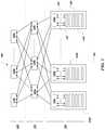
- FIG. 1is a representative network topology of a data center 100 including a spine layer 110 , a fabric, aggregation, or distribution layer 120 , and a leaf layer 130 .
- the spine layer 110includes switching or routing devices, including device 110 a , 110 b , and 110 c ;
- the fabric layer 120includes switching or routing devices, including device 120 a , 120 b , and 120 c ;
- the leaf layer 130includes switching or routing devices, including device 130 a , 130 b , and 130 c .
- the servers 135are contained in server racks such as server rack 139 a , 139 b , and 139 c .
- the server racksare arranged in a server cabinet row 150 .
- the spine layer 110performs switching or routing using the spine layer devices such as 110 a , 110 b , 110 c , and others.
- data packetscan be propagated through data center 100 by being directed by devices 110 a , 110 b , and 110 c of spine layer 110 to devices 120 a , 120 b , and 120 c of fabric layer 120 .
- These spine layer devicesare can be connected to a network external to the data center.
- the fabric, aggregation, or distribution layer 120performs switching or routing using the fabric layer devices such as 120 a , 120 b , 120 c , and others.
- the fabric layerredundantly interconnects the leaf layer 130 devices to the spine layer 110 devices.
- the switching devices in the leaf layer 130can be located at the top of the rack (TOR) and connect to data center devices such as servers 135 through copper links 137 or fiber optic links 138 .
- the switching devices in the leaf layer 130may also connect to firewalls, load balancers, edge routers, and other devices such as client devices. It will be appreciated that the use of three devices in each layer above is only exemplary, and more devices could be added depending on the needs of the data center.
- the spine layer 110is also called the core layer, and the leaf layer 130 is also called the access layer.
- the distribution layer 120is merged into the leaf layer 130 and spine layer 110 such that every leaf layer device ( 130 a , 130 b , 130 c , . . . ) connects to every spine layer device ( 110 a , 110 b , 110 c , . . . ).
- the connection from each of the leaf layer 130 device to each of the spine layer 110 devicecould be either in layer 2 (i.e., switched) or in layer 3 (i.e., routed).
- FIG. 2is a representative block diagram of an exemplary lightweight pre-sorting routing or switching device 200 .
- Device 200is pluggable, modular, and scalable and includes a number of input-out (I/O) ingress ports 220 and egress ports 210 .
- I/Oinput-out
- device 200may be viewed as a lightweight or barebones version of traditional switching or routing devices that may be found within the fabric/distribution/aggregation layer 120 or leaf/access layer 130 . That is, device 200 might include less complex functionality than other switching or routing devices found within aggregation layer 120 or leaf/access layer 130 .
- device 200is contained within a traditional switching or routing device to presort traffic for the switching or routing device.
- Device 200includes a routing/switching engine 240 to perform a fast and truncated layer 2 switching or layer 3 routing using substantially less than the layer 2 or layer 3 packet header information (i.e., aspects of layer 2 or layer 3, respectively). For example, it may use only 1 or just a few bits of the destination information in the packet header where the destination information includes, for example, the destination IP address or the destination port number. In some exemplary embodiments, just 1 bit of a destination information is used to route the traffic either east or west. By contrast, the routers found within aggregation layer 120 or leaf/access layer 130 might use more bits of the destination information in the packet header to determine where to route the traffic.
- the layer 2 or layer 3 packet header informationi.e., aspects of layer 2 or layer 3, respectively. For example, it may use only 1 or just a few bits of the destination information in the packet header where the destination information includes, for example, the destination IP address or the destination port number. In some exemplary embodiments, just 1 bit of a destination information is used to route the traffic
- the routers found within aggregation layer 120 or leaf/access layer 130might use sixteen bits (e.g., either including or excluding the bits considered by device 200 ).
- device 200might consider the first three bits, but the routers found within aggregation layer 120 or leaf/access layer 130 might consider the following seven bits. That is, device 200 and the routers found within aggregation layer 120 or leaf/access layer 130 might consider bits of the header within different positions when making their routing determinations.
- the truncated routing/switching of device 200is accomplished by the routing/switching engine 240 together with a memory 250 which includes look-up tables or forwarding tables representing or indicating the destinations for the few bits of the destination information considered by device 200 . That is, different characteristics of the header and/or destination information can be considered by device 200 to determine where to route the data packets. Because of the truncated nature of the routing/switching only a small amount of memory is required in many exemplary embodiments. For example, this forwarding table memory element could store the mapping between the destination information in the packets' header and action the device should take such as whether a logic “1” in a certain bit position in the destination information corresponds to “eastward” routing or “westward” routing.
- Device 200performs preliminary routing using a small portion of the packet information, and downstream routers act on the remaining portion of the packet information (e.g., more of the header corresponding to the destination information, as previously discussed) to determine the actual destination. For example, once the routing/switching engine 240 determines that the packet should be routed eastward, a router on the east would route to the eventual destination using the remaining portion of the packet header. In some implementations, to the routing corresponds to either layer 2 switching or layer 3 routing functions.
- device 200is reconfigurable to enable routing/switching engine 240 (e.g., implemented by a controller or processor circuit) to perform different types of packet redirection.
- a memory devicesuch as memory 250 or some other storage device within device 200 can store the current configured routing/switching scheme.
- device 200may be configured to look at a variable number of bits in the packet header to pre-sort traffic.
- a controller circuitcan provide information to device 200 (or multiple devices 200 ) to update memory 250 such that device 200 may be configured to only look at 1 bit of a destination information to determine if to route the packet eastward or westward; in another example device 200 may be configured to look at 2 bits of the destination information to determine if to route the packet in one of two eastward destination devices or in one of two westward destination devices for a total of four possible destinations.
- device 200might only consider a single bit of the destination information, be reconfigured via the controller circuit, and then consider two bits of the destination information.
- Device 200may also include rules on which of the destination devices to send the packet to when more than one destination is possible. For example, when device 200 is configured to inspect 2 bits of the packet header and route the packet to one of two eastward routers/switches, it may select which one of the eastward routers/switches to send it to in a round-robin fashion; first match goes to router 1 , second match to router 2 , third match back to router 1 , etc. Alternatively, in some exemplary embodiments, the selection of which router to send the packet to among a number of routers could be based on a preconfigured priority ordering which may bias some routers relative to others. For example, a priority routing scheme may configure device 200 to route every fourth match meeting the presorting criteria to router 1 and the rest of the matches to router 2 .
- data center 100may implement customized addressing based on, for example, the underlying applications running on the servers 135 . This is particularly attractive when the same entity owns both the data center and the underlying applications and where the majority of the traffic within the data center is east-west (e.g., from servers to storage).
- the ability to customize the address spaceleads to a reduction in complexity of device 200 and in turn a reduction in complexity of routers and switches used with device 200 .
- the addressingmay be customized such that a single bit position in the packet header informs the router/switch engine whether to route the packet eastward or westward.
- device 200is not limited to a specific layer 2 or layer 3 routing protocol, for example the OSPF (open shortest path first) protocol used for layer 3 routing in spine-leaf architectures or the STP (Spanning Tree Protocol).
- Device 200need not be part of an interior gateway protocol (IGP). It may be used to shape or load balance the data center traffic.
- IGPinterior gateway protocol
- device 200may be used within a switch and use layer 2 tunneling protocol (L2TP).
- device 200may use MPLS (multi-protocol label switching) for load balancing using entropy labels to distribute the traffic on the router/switch board. It may include a pure MPLS device with simple overhead inspection, or perform segmented routing allowing for traffic steering.
- Device 200may be used both for light weight overhead inspection to sort out traffic or for network sniffing, for example in an IPS (intrusion prevention system) or IDS (intrusion detection system) or a firewall.
- IPSintrusion prevention system
- IDSintrusion detection system
- ingress ports 220 and egress ports 210may support copper or fiber-optic media.
- device 200may be silicon photonics based where data is transferred within device 200 by optical rays rather than electrical conductors.
- a silicon photonics devicee.g., semiconductor circuit
- Thisallows for economical and fast pre-routing/pre-sorting which offloads and balances the traffic loads from downstream routers/switches.
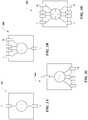
- FIGS. 3A-3Dare representative blocks diagrams of exemplary pre-sorting router/switch devices 200 configured for a variable number of ingress ports 220 and a variable number of egress ports 210 .
- FIG. 3Ashows an example of a device 310 configured to ingress traffic from one ingress port (e.g., receive a data packet at an input port) and egress traffic from one egress port (e.g., provide a data packet at an output port).
- FIG. 3Bshows an example of a device 320 configured to ingress traffic from one ingress port and egress traffic from M egress ports.
- FIG. 3Cshows an example of a device 330 configured to ingress traffic from N ingress ports and egress traffic from one egress port.
- FIG. 3Ashows an example of a device 310 configured to ingress traffic from one ingress port (e.g., receive a data packet at an input port) and egress traffic from one egress port (e.g., provide
- 3Dshows an example of a device 340 configured to ingress traffic from N ingress ports and egress traffic from M egress ports.
- the number of ingress and egress portsmay be determined through software configuration of device 200 such as where a single physical port may be associated with multiple virtual ports. Additionally, the number of ingress and egress ports of device 200 need not match the number of ingress/egress ports of a router/switch device associated with device 200 (i.e., the post-sorting router/switch integrated on the same board as device 200 or otherwise downstream to device 200 ).
- routing traffic from a QSFP28 transceivermay use a 4:1 ingress:egress configuration of device 330 and be further configured to select one of the 28 Gbps stream from the ingress port and route it to the egress port.
- Different configurations of devices 310 , 320 , 330 , and 340may be used to perform layer 3 inspection and routing per stream/wavelength or per fiber input.
- FIG. 4is a representative data center architecture 400 according to one exemplary embodiment.
- Data center 400includes a spine layer 410 , a fabric, aggregation, or distribution layer 420 , and a leaf layer 430 .
- the spine layer 410includes switching or routing devices, including device 410 a , 410 b , 410 c , and 410 d ;
- the fabric layer 420includes switching or routing devices, including device 420 a , 420 b , 420 c , and 420 d ;
- the leaf layer 430includes switching or routing devices, including device 430 a , 430 b , and 430 c .
- 405 ais the input-out (I/O) layer associated with the ingress ports of the spine layer 410 ; 405 b is the I/O layer associated with the egress ports of the spine layer 410 ; 415 a is the I/O layer associated with the ingress ports of the aggregation layer 420 ; and 415 b is the I/O layer associated with the egress ports of the aggregation layer 420 .
- the spine layer 410is also called the core layer and the leaf layer 430 is also called the access layer.
- the distribution layer 420is merged into the leaf layer 430 and spine layer 410 such that every leaf layer device ( 430 a , 430 b , 430 c , . . . ) may connect to every spine layer device ( 410 a , 410 b , 410 c , 410 d , . . . ).
- any or all of the devices in spine layer 410 , fabric layer 420 , or leaf layer 430may incorporate pre-routing device 200 . Even for a leaf-spine architecture, leaf or spine layer devices which include the pre-routing device 200 (or device 310 , 320 , 330 , or 340 ) need not have a direct connection to each other because the pre-routing device may group the leaf/spine layer devices so as to reduce the interconnect complexity and large cable counts within the data center.
- spine layer 410can include device 200 and the other layers (e.g., fabric layer 420 and leaf layer 430 ) can include more complex switches.
- device 200 within spine layer 410can provide some pre-routing of data packets based on a smaller portion of the header indicating the destination information (or number of bits, different positions of bits, or other characteristics of the header and/or destination information as discussed herein) and the other routing/switching devices of the other layers can provide routing based on a larger portion of the header indicating the destination information.
- a quick and simplified routingcan be first performed by device 200 to direct the data packets to more complex routing functionalities of the other routing/switching devices.
- FIG. 5shows an exemplary flow diagram 500 for routing traffic within a data center 400 .
- the routing/switching devicewhich contains the pre-routing devices 200 , 310 , 320 , 330 , or 340 determines a configuration for the ingress and egress ports. For example, if a device 420 a includes a total of M ports; at block 510 an ingress/egress configuration may configure the first N ports as ingress ports and the rest M-N ports as egress ports.
- the pre-routing device 200receives packets in the configured ingress ports.
- the pre-routing device 200determines a pre-sorting rule configuration.
- Pre-sorting rulesmay include, for example, sorting based on protocol stack layer such as by sorting ingress port traffic via layer 2 or layer 3 header information.
- Pre-sorting rulesmay also include, for example, pre-sorting depth based on coarse or fine aggregation of downstream routers/switches. That is, the pre-routing device 200 may be configured to finely select the downstream device or broadly select a downstream device from a number of devices. This may be performed, for example, by determining how many bits of the packet header to inspect by accessing memory 250 to obtain the look-up tables or forwarding tables representing or indicating the destinations for the few bits of the destination information considered by device 200 .
- An example of a coarse/broad pre-sortingmay be a configuration where device 200 inspects only 1 bit from a packet header to determine if it should route the packet eastward or westward.
- device 420 amay be configured to route packets to either 410 a or 410 b when the inspected bit is logic 1, and to either 410 c or 410 d when the inspected bit is logic 0.
- An example of a fine/narrow pre-sortingmay be a configuration where device 200 routes the packet to a specific downstream switch/router. In some exemplary embodiments an inspection of n bits of the header would result in 2n possible aggregation levels of routing.
- a logic 1 in a packet headercould map to a first row in look-up table which would indicate a routing to a certain subset of downstream routers/switches.
- the pre-sorting rulesmay also include how to select which downstream device within a group of downstream devices to route to. For example, if device 420 a is configured to route packets to either 410 a or 410 b it may alternatively route to each of these device on every match or it may be more biased towards routing to one device versus another, or use any other formula to determine which device within the matched group gets the packets.
- the pre-routing device 200inspects the packets received in the ingress ports in block 520 based on the pre-sorting rule determined in block 530 .
- the pre-routing device 200sends the packet to the determined egress port corresponding to the determined destination determined using the pre-sorting rule in block 530 .
- device 200within the data center routers/switches, including when used in conjunction with customized address spaces, overcomes the problem with unconstrained connectivity required to handle east-west traffic which is particularly problematic for leaf-spine data center architectures. For example, rather than every leaf layer device (e.g., 410 a , 410 b , 410 c , 410 d . . . ) connecting to every spine layer device (e.g., 430 a , 430 b , 430 c , . . .
- some exemplary embodimentsmay connect a group of leaf devices to a group of spine devices where one or more routers/switches with device 200 s are interposed between each leaf and spine device to presort the traffic between the groups. Reducing the complexity and volume of traffic at each node allows for the use of less expensive and less power-hungry routing/switching devices or can lead for higher throughput and reduced latency.
- the device 200's presorting/preliminary routing functions and its cascading modular design allows for data center topology optimization supporting software-defined networking (SDN) architectures.
- SDNsoftware-defined networking
- device 200may be dynamically reconfigured to presort traffic based on some criteria thereby allowing a network administrator to shape traffic from a centralized console without having to touch individual device 200 s or spine and aggregation layer switches making up the control plane.
- Device 200thereby allows for a flexible data center design and may be used to adapt traffic patterns particularly for non-block fabric architecture (leaf-spine architectures).
- SDN programmabilityis not in software but the network topology is instead shaped by the modularity of the presorting/preliminary router than can be plugged in and out and reconfigured as needed.
- the data centermixes and matches different presorting switch/router devices depending on network topology and underlying application data.
- Device 200 as used in data center 400 with flow 500has numerous benefits to the overall data center architecture. For example, they allow for small switches with focus on layer 2 (and “heavy weight”) and intelligent termination points; allows for any combination of lighter and pluggable devices and “heavy weight” switches, even allowing for I/O layers without switches/router or fully equipped switches/routers; provides for better security appliances and termination because address resolution protocol (ARP) can be done in local pluggable devices. Additionally, device 200 allows for interoperability with existing or future pluggable optics standards which allows for a high degree of freedom to mix in new switching/optical technologies as they become available for the data center layers.
- ARPaddress resolution protocol
- FIG. 6is a block diagram of a computer system as may be used to implement features of some of the embodiments, for example, the functionalities and techniques of device 200 , as described herein.
- the computing system 600may include one or more central processing units (“processors”) 605 , memory 610 , input/output devices 625 (e.g., keyboard and pointing devices, display devices), storage devices 620 (e.g., disk drives), and network adapters 630 (e.g., network interfaces) that are connected to an interconnect 615 .
- the interconnect 615is illustrated as an abstraction that represents any one or more separate physical buses, point to point connections, or both connected by appropriate bridges, adapters, or controllers.
- the interconnect 615may include, for example, a system bus, a Peripheral Component Interconnect (PCI) bus or PCI-Express bus, a HyperTransport or industry standard architecture (ISA) bus, a small computer system interface (SCSI) bus, a universal serial bus (USB), IIC (I2C) bus, or an Institute of Electrical and Electronics Engineers (IEEE) standard 1394 bus, also called Firewire.
- PCIPeripheral Component Interconnect
- ISAindustry standard architecture
- SCSIsmall computer system interface
- USBuniversal serial bus
- I2CIIC
- IEEEInstitute of Electrical and Electronics Engineers
- the memory 610 and storage devices 620are computer-readable storage media that may store instructions that implement at least portions of the various embodiments.
- the data structures and message structuresmay be stored or transmitted via a data transmission medium, for example, a signal on a communications link.
- Various communications linksmay be used, for example, the Internet, a local area network, a wide area network, or a point-to-point dial-up connection.
- computer readable mediacan include computer-readable storage media (e.g., “non-transitory” media) and computer-readable transmission media.
- the instructions stored in memory 610can be implemented as software and/or firmware to program the processor(s) 605 to carry out actions described above.
- such software or firmwaremay be initially provided to the processing system 600 by downloading it from a remote system through the computing system 600 (e.g., via network adapter 630 ).
Landscapes
- Engineering & Computer Science (AREA)
- Computer Networks & Wireless Communication (AREA)
- Signal Processing (AREA)
- Data Exchanges In Wide-Area Networks (AREA)
- Computer Security & Cryptography (AREA)
Abstract
Description
Claims (20)
Priority Applications (1)
| Application Number | Priority Date | Filing Date | Title |
|---|---|---|---|
| US16/537,287US11012354B2 (en) | 2017-10-04 | 2019-08-09 | Pre-routing device for data centers |
Applications Claiming Priority (2)
| Application Number | Priority Date | Filing Date | Title |
|---|---|---|---|
| US15/725,239US10425331B2 (en) | 2017-10-04 | 2017-10-04 | Pre-routing device for data centers |
| US16/537,287US11012354B2 (en) | 2017-10-04 | 2019-08-09 | Pre-routing device for data centers |
Related Parent Applications (1)
| Application Number | Title | Priority Date | Filing Date |
|---|---|---|---|
| US15/725,239ContinuationUS10425331B2 (en) | 2017-10-04 | 2017-10-04 | Pre-routing device for data centers |
Publications (2)
| Publication Number | Publication Date |
|---|---|
| US20190363983A1 US20190363983A1 (en) | 2019-11-28 |
| US11012354B2true US11012354B2 (en) | 2021-05-18 |
Family
ID=65898164
Family Applications (2)
| Application Number | Title | Priority Date | Filing Date |
|---|---|---|---|
| US15/725,239ActiveUS10425331B2 (en) | 2017-10-04 | 2017-10-04 | Pre-routing device for data centers |
| US16/537,287Expired - Fee RelatedUS11012354B2 (en) | 2017-10-04 | 2019-08-09 | Pre-routing device for data centers |
Family Applications Before (1)
| Application Number | Title | Priority Date | Filing Date |
|---|---|---|---|
| US15/725,239ActiveUS10425331B2 (en) | 2017-10-04 | 2017-10-04 | Pre-routing device for data centers |
Country Status (1)
| Country | Link |
|---|---|
| US (2) | US10425331B2 (en) |
Cited By (2)
| Publication number | Priority date | Publication date | Assignee | Title |
|---|---|---|---|---|
| US11843536B1 (en) | 2023-01-18 | 2023-12-12 | Bank Of America Corporation | Systems, methods, and apparatuses for determining data routing in an electronic environment |
| US12170609B2 (en) | 2023-01-23 | 2024-12-17 | Bank Of America Corporation | Systems, methods, and apparatuses for determining data transmission destinations across an electronic network |
Families Citing this family (3)
| Publication number | Priority date | Publication date | Assignee | Title |
|---|---|---|---|---|
| US11405325B2 (en)* | 2019-06-05 | 2022-08-02 | Dell Products L.P. | In-band-telemetry-based path MTU size determination system |
| US11949595B2 (en)* | 2020-06-26 | 2024-04-02 | Intel Corporation | Reflection routing as a framework for adaptive modular load balancing for multi-hierarchy network on chips |
| WO2024229006A1 (en) | 2023-05-01 | 2024-11-07 | Neuraly, Inc. | Glucagon-like peptide-1 receptor agonist variants and methods thereof |
Citations (40)
| Publication number | Priority date | Publication date | Assignee | Title |
|---|---|---|---|---|
| US5629836A (en) | 1994-08-25 | 1997-05-13 | Dzus Fastener Europe Ltd. | Lever mechanism |
| US5729752A (en) | 1993-02-19 | 1998-03-17 | Hewlett-Packard Company | Network connection scheme |
| US5997326A (en) | 1998-08-31 | 1999-12-07 | 3Com Corp. | Apparatus and method for mounting a circuit board assembly to an electronic chassis |
| US6373713B1 (en) | 2000-09-28 | 2002-04-16 | Oresis Communications | Single handle printed circuit board assembly insertion, extraction, sensing and locking mechanism |
| US6381146B1 (en) | 2000-09-28 | 2002-04-30 | Hewlett-Packard Company | Module removal system |
| US6422876B1 (en) | 1999-12-08 | 2002-07-23 | Nortel Networks Limited | High throughput interconnection system using orthogonal connectors |
| US20030080568A1 (en) | 2001-10-30 | 2003-05-01 | Egenera, Inc. | Latching mechanism for securing a computer component into a housing |
| US6637846B2 (en) | 2001-04-04 | 2003-10-28 | Wistron Corporation | Exit apparatus for computer modules |
| US20030218978A1 (en)* | 2002-05-24 | 2003-11-27 | Mosaid Technologies, Inc. | Method and apparatus for reordering entries in a multi probe lookup |
| US20040002237A1 (en) | 2002-06-28 | 2004-01-01 | Doblar Drew G. | Circuit board orientation in a computer system |
| US20040047128A1 (en) | 2002-09-09 | 2004-03-11 | Compaq Information Technologies Group, L.P. | Multipurpose server handle |
| US6814582B2 (en) | 2002-11-08 | 2004-11-09 | Force Computers, Inc. | Rear interconnect blade for rack mounted systems |
| US20050207134A1 (en) | 2004-03-16 | 2005-09-22 | Belady Christian L | Cell board interconnection architecture |
| US20060049727A1 (en) | 2004-09-07 | 2006-03-09 | Corsini Peter H | Integrated chassis assembly |
| US20060121421A1 (en) | 2004-10-15 | 2006-06-08 | Spitaels James S | IT equipment simulation |
| US7092642B2 (en) | 2000-08-04 | 2006-08-15 | Fujitsu Limited | Tunable channel spacing for wavelength division multiplexing (WDM) transport system |
| US20070184676A1 (en) | 2006-02-07 | 2007-08-09 | Fci Americas Technology, Inc. | Interconnected printed circuit boards |
| US20070248086A1 (en)* | 2006-04-24 | 2007-10-25 | Brian Petersen | Network switching system having variable headers and addresses |
| US7435095B1 (en) | 2007-06-11 | 2008-10-14 | Hon Hai Precision Ind. Co., Ltd. | Electrical interconnection system |
| US20110013348A1 (en) | 2009-03-17 | 2011-01-20 | Seibold Lawrence B | Apparatus and Method for Power Distribution to and Cooling of Computer Components on Trays in a Cabinet |
| US8154867B2 (en) | 2010-03-10 | 2012-04-10 | Ciena Corporation | High density switching platform with interbay connections arrangement |
| US20120120596A1 (en) | 2010-11-16 | 2012-05-17 | Arista Networks, Inc. | Air cooling architecture for network switch chassis with orthogonal midplane |
| US20130083798A1 (en)* | 2011-09-29 | 2013-04-04 | Sridhar Lakshmanamurthy | Sending Packets With Expanded Headers |
| US20130337665A1 (en) | 2004-07-01 | 2013-12-19 | Amphenol Corporation | Midplane Especially Applicable to an Orthogonal Architecture Electronic System |
| US20140098492A1 (en) | 2012-10-05 | 2014-04-10 | Cisco Technology, Inc. | Air flow system |
| US20140206273A1 (en) | 2007-11-19 | 2014-07-24 | Ortronics, Inc. | Equipment Rack and Associated Ventilation System |
| US20140307400A1 (en) | 2013-04-10 | 2014-10-16 | International Business Machines Corporation | Latching cam handle assembly for securing mated circuit boards |
| US20140362874A1 (en) | 2013-06-06 | 2014-12-11 | Fujitsu Optical Components Limited | Optical transmitter, optical receiver and optical transceiver |
| US20150229438A1 (en) | 2012-09-06 | 2015-08-13 | Emmanuel Le Taillandier De Gabory | System and method for transmitting optical signal over multiple channels |
| US9136624B1 (en) | 2013-03-28 | 2015-09-15 | Juniper Networks, Inc. | Orthogonal cross-connecting of printed circuit boards without a midplane board |
| US20160077556A1 (en) | 2014-09-16 | 2016-03-17 | Cisco Technology, Inc. | Faceplate for a Computing Device |
| US20160128230A1 (en) | 2014-11-03 | 2016-05-05 | Cisco Technology, Inc. | Double-angled faceplate for air flow system |
| US20160197679A1 (en) | 2015-01-07 | 2016-07-07 | Fujitsu Limited | Device and method for transmitting multicarrier signals |
| US20160285758A1 (en) | 2015-03-27 | 2016-09-29 | Nec Corporation | Integrated circuit, semiconductor device, card and data transfer method |
| US20170048144A1 (en)* | 2015-08-13 | 2017-02-16 | Futurewei Technologies, Inc. | Congestion Avoidance Traffic Steering (CATS) in Datacenter Networks |
| US9686886B2 (en) | 2013-12-11 | 2017-06-20 | Hitachi, Ltd. | Cooling mechanism of storage control apparatus |
| US20170195259A1 (en)* | 2016-01-05 | 2017-07-06 | Knuedge, Inc. | Flow control through packet router |
| US20170245030A1 (en) | 2016-02-19 | 2017-08-24 | Facebook, Inc. | Wavelength division multiplexer with packet switching based on header information or performance metric information for optical channels |
| US20170257315A1 (en) | 2016-03-04 | 2017-09-07 | Oracle International Corporation | System and method for supporting sma level abstractions at router ports for enablement of data traffic in a high performance computing environment |
| US20170331766A1 (en) | 2016-05-11 | 2017-11-16 | Facebook, Inc. | Modular network switches, associated structures, and associated methods of manufacture and use |
- 2017
- 2017-10-04USUS15/725,239patent/US10425331B2/enactiveActive
- 2019
- 2019-08-09USUS16/537,287patent/US11012354B2/ennot_activeExpired - Fee Related
Patent Citations (45)
| Publication number | Priority date | Publication date | Assignee | Title |
|---|---|---|---|---|
| US5729752A (en) | 1993-02-19 | 1998-03-17 | Hewlett-Packard Company | Network connection scheme |
| US5629836A (en) | 1994-08-25 | 1997-05-13 | Dzus Fastener Europe Ltd. | Lever mechanism |
| US5997326A (en) | 1998-08-31 | 1999-12-07 | 3Com Corp. | Apparatus and method for mounting a circuit board assembly to an electronic chassis |
| US6422876B1 (en) | 1999-12-08 | 2002-07-23 | Nortel Networks Limited | High throughput interconnection system using orthogonal connectors |
| US7092642B2 (en) | 2000-08-04 | 2006-08-15 | Fujitsu Limited | Tunable channel spacing for wavelength division multiplexing (WDM) transport system |
| US6373713B1 (en) | 2000-09-28 | 2002-04-16 | Oresis Communications | Single handle printed circuit board assembly insertion, extraction, sensing and locking mechanism |
| US6381146B1 (en) | 2000-09-28 | 2002-04-30 | Hewlett-Packard Company | Module removal system |
| US6637846B2 (en) | 2001-04-04 | 2003-10-28 | Wistron Corporation | Exit apparatus for computer modules |
| US20030080568A1 (en) | 2001-10-30 | 2003-05-01 | Egenera, Inc. | Latching mechanism for securing a computer component into a housing |
| US20030218978A1 (en)* | 2002-05-24 | 2003-11-27 | Mosaid Technologies, Inc. | Method and apparatus for reordering entries in a multi probe lookup |
| US20040002237A1 (en) | 2002-06-28 | 2004-01-01 | Doblar Drew G. | Circuit board orientation in a computer system |
| US7050307B2 (en) | 2002-06-28 | 2006-05-23 | Sun Microsystems, Inc. | Circuit board orientation in a computer system |
| US20040047128A1 (en) | 2002-09-09 | 2004-03-11 | Compaq Information Technologies Group, L.P. | Multipurpose server handle |
| US6814582B2 (en) | 2002-11-08 | 2004-11-09 | Force Computers, Inc. | Rear interconnect blade for rack mounted systems |
| US20050207134A1 (en) | 2004-03-16 | 2005-09-22 | Belady Christian L | Cell board interconnection architecture |
| US20130337665A1 (en) | 2004-07-01 | 2013-12-19 | Amphenol Corporation | Midplane Especially Applicable to an Orthogonal Architecture Electronic System |
| US20060049727A1 (en) | 2004-09-07 | 2006-03-09 | Corsini Peter H | Integrated chassis assembly |
| US20060121421A1 (en) | 2004-10-15 | 2006-06-08 | Spitaels James S | IT equipment simulation |
| US20070184676A1 (en) | 2006-02-07 | 2007-08-09 | Fci Americas Technology, Inc. | Interconnected printed circuit boards |
| US20070248086A1 (en)* | 2006-04-24 | 2007-10-25 | Brian Petersen | Network switching system having variable headers and addresses |
| US7435095B1 (en) | 2007-06-11 | 2008-10-14 | Hon Hai Precision Ind. Co., Ltd. | Electrical interconnection system |
| US20140206273A1 (en) | 2007-11-19 | 2014-07-24 | Ortronics, Inc. | Equipment Rack and Associated Ventilation System |
| US20110013348A1 (en) | 2009-03-17 | 2011-01-20 | Seibold Lawrence B | Apparatus and Method for Power Distribution to and Cooling of Computer Components on Trays in a Cabinet |
| US8154867B2 (en) | 2010-03-10 | 2012-04-10 | Ciena Corporation | High density switching platform with interbay connections arrangement |
| US20120120596A1 (en) | 2010-11-16 | 2012-05-17 | Arista Networks, Inc. | Air cooling architecture for network switch chassis with orthogonal midplane |
| US20130083798A1 (en)* | 2011-09-29 | 2013-04-04 | Sridhar Lakshmanamurthy | Sending Packets With Expanded Headers |
| US20150229438A1 (en) | 2012-09-06 | 2015-08-13 | Emmanuel Le Taillandier De Gabory | System and method for transmitting optical signal over multiple channels |
| US20140098492A1 (en) | 2012-10-05 | 2014-04-10 | Cisco Technology, Inc. | Air flow system |
| US9136624B1 (en) | 2013-03-28 | 2015-09-15 | Juniper Networks, Inc. | Orthogonal cross-connecting of printed circuit boards without a midplane board |
| US20140307400A1 (en) | 2013-04-10 | 2014-10-16 | International Business Machines Corporation | Latching cam handle assembly for securing mated circuit boards |
| US20140362874A1 (en) | 2013-06-06 | 2014-12-11 | Fujitsu Optical Components Limited | Optical transmitter, optical receiver and optical transceiver |
| US9686886B2 (en) | 2013-12-11 | 2017-06-20 | Hitachi, Ltd. | Cooling mechanism of storage control apparatus |
| US20160077556A1 (en) | 2014-09-16 | 2016-03-17 | Cisco Technology, Inc. | Faceplate for a Computing Device |
| US20160128230A1 (en) | 2014-11-03 | 2016-05-05 | Cisco Technology, Inc. | Double-angled faceplate for air flow system |
| US20160197679A1 (en) | 2015-01-07 | 2016-07-07 | Fujitsu Limited | Device and method for transmitting multicarrier signals |
| US20160285758A1 (en) | 2015-03-27 | 2016-09-29 | Nec Corporation | Integrated circuit, semiconductor device, card and data transfer method |
| US20170048144A1 (en)* | 2015-08-13 | 2017-02-16 | Futurewei Technologies, Inc. | Congestion Avoidance Traffic Steering (CATS) in Datacenter Networks |
| US20170195259A1 (en)* | 2016-01-05 | 2017-07-06 | Knuedge, Inc. | Flow control through packet router |
| US20170245030A1 (en) | 2016-02-19 | 2017-08-24 | Facebook, Inc. | Wavelength division multiplexer with packet switching based on header information or performance metric information for optical channels |
| US20170257315A1 (en) | 2016-03-04 | 2017-09-07 | Oracle International Corporation | System and method for supporting sma level abstractions at router ports for enablement of data traffic in a high performance computing environment |
| US20170331766A1 (en) | 2016-05-11 | 2017-11-16 | Facebook, Inc. | Modular network switches, associated structures, and associated methods of manufacture and use |
| US20170332519A1 (en) | 2016-05-11 | 2017-11-16 | Facebook, Inc. | Modular network switches, associated structures, and associated methods of manufacture and use |
| US20170332506A1 (en) | 2016-05-11 | 2017-11-16 | Facebook, Inc. | Modular network switches, associated structures, and associated methods of manufacture and use |
| US20170332518A1 (en) | 2016-05-11 | 2017-11-16 | Facebook, Inc. | Modular network switches, associated structures, and associated methods of manufacture and use |
| US20170329371A1 (en) | 2016-05-11 | 2017-11-16 | Facebook, Inc. | Modular network switches, associated structures, and associated methods of manufacture and use |
Non-Patent Citations (18)
| Title |
|---|
| Corrected Notice of Allowability dated Nov. 21, 2017 for U.S. Appl. No. 15/291,313 by Schmidtke, H., et al., filed Oct. 12, 2016. |
| European Perforators Association "The Advantages of Perporated Metals" Aug. 21, 2016, EUROPERF. |
| Non-Final Office Action dated Aug. 29, 2017 for U.S. Appl. No. 15/291,293 by Schmidtke, H., et al., filed Oct. 12, 2016. |
| Non-Final Office Action dated Jun. 15, 2017 for U.S. Appl. No. 15/338,255 by Lyubomirsky, I., et al., filed Oct. 28, 2016. |
| Non-Final Office Action dated Nov. 17, 2017 for U.S. Appl. No. 15/291,348 by Schmidtke, H. et al., filed Oct. 12, 2016. |
| Non-Final Office Action dated Nov. 24, 2017 for U.S. Appl. No. 15/291,263 by Schmidtke, H., et al., filed Oct. 12, 2016. |
| Notice of Allowance dated Dec. 6, 2017 for U.S. Appl. No. 15/291,293 by Schmidtke, H., et al., filed Oct. 12, 2016. |
| Notice of Allowance dated Jul. 3, 2017 of U.S. Appl. No. 15/291,313 of Schmidtke H., et al., filed Oct. 12, 2016. |
| U.S. Appl. No. 15/291,263 by Schmidtke, H., et al., filed Oct. 12, 2016. |
| U.S. Appl. No. 15/291,293 by Schmidtke, H., et al., filed Oct. 12, 2016. |
| U.S. Appl. No. 15/291,313 by Schmidtke, H., et al., filed Oct. 12, 2016. |
| U.S. Appl. No. 15/291,324 by Schmidtke, H., et al., filed Oct. 12, 2016. |
| U.S. Appl. No. 15/291,348 by Schmidtke, H., et al., filed Oct. 12, 2016. |
| U.S. Appl. No. 15/338,255 by Lyubomirsky, I., et al., filed Oct. 28, 2016. |
| U.S. Appl. No. 15/655,795 by Schmidtke, H. et al. filed Jul. 20, 2017. |
| U.S. Appl. No. 15/705,205 by Schmidtke, H. et al. filed Sep. 14, 2017. |
| U.S. Appl. No. 15/706,561 by Schmidtke, H. et al. filed Sep. 15, 2017. |
| U.S. Appl. No. 15/716,454 by Schmidtke, K. filed Sep. 26, 2017. |
Cited By (2)
| Publication number | Priority date | Publication date | Assignee | Title |
|---|---|---|---|---|
| US11843536B1 (en) | 2023-01-18 | 2023-12-12 | Bank Of America Corporation | Systems, methods, and apparatuses for determining data routing in an electronic environment |
| US12170609B2 (en) | 2023-01-23 | 2024-12-17 | Bank Of America Corporation | Systems, methods, and apparatuses for determining data transmission destinations across an electronic network |
Also Published As
| Publication number | Publication date |
|---|---|
| US20190104062A1 (en) | 2019-04-04 |
| US20190363983A1 (en) | 2019-11-28 |
| US10425331B2 (en) | 2019-09-24 |
Similar Documents
| Publication | Publication Date | Title |
|---|---|---|
| US11012354B2 (en) | Pre-routing device for data centers | |
| US20230231799A1 (en) | Data center network with packet spraying | |
| US11509538B2 (en) | Network interconnect as a switch | |
| US11469922B2 (en) | Data center network with multiplexed communication of data packets across servers | |
| US8767529B2 (en) | High availability distributed fabric protocol (DFP) switching network architecture | |
| Besta et al. | High-performance routing with multipathing and path diversity in ethernet and HPC networks | |
| US8289977B2 (en) | Two-layer switch apparatus avoiding first layer inter-switch traffic in steering packets through the apparatus | |
| CN102571554B (en) | Methods and apparatus for forwarding-state transport in a distributed control plane | |
| US11070474B1 (en) | Selective load balancing for spraying over fabric paths | |
| US20120155453A1 (en) | Methods and apparatus related to a switch fabric system having a multi-hop distributed control plane and a single-hop data plane | |
| US8462636B2 (en) | Systems and methods for communication of management traffic over link aggregation group interface for a network element with distributed architecture | |
| US9461938B2 (en) | Large distributed fabric-based switch using virtual switches and virtual controllers | |
| US9565277B2 (en) | Dual-homed external network access in a distributed internet protocol (IP) router | |
| US9385939B2 (en) | Method and a controller system for configuring a software-defined network | |
| CN113841364A (en) | System, method and architecture for data center network switching | |
| Hermsmeyer et al. | Towards 100G packet processing: Challenges and technologies | |
| US20040071141A1 (en) | Distributed service architecture based on a hierarchical load balancing approach | |
| US8942232B1 (en) | Multi-stage switching topology | |
| Dürr | A flat and scalable data center network topology based on De Bruijn graphs | |
| US9432291B2 (en) | Method and a device for defining a look-up system for a network element of a software-defined network | |
| Shiraki et al. | Managing storage flows with SDN approach in I/O converged networks | |
| Anne | Case Study: Using Business Process Modeling Notation and Agile Test-Driven Design Methodology for Business Continuity Planning | |
| KR20050017171A (en) | Network Router having Load Balancer for Processing IP Packet |
Legal Events
| Date | Code | Title | Description |
|---|---|---|---|
| FEPP | Fee payment procedure | Free format text:ENTITY STATUS SET TO UNDISCOUNTED (ORIGINAL EVENT CODE: BIG.); ENTITY STATUS OF PATENT OWNER: LARGE ENTITY | |
| STPP | Information on status: patent application and granting procedure in general | Free format text:DOCKETED NEW CASE - READY FOR EXAMINATION | |
| STPP | Information on status: patent application and granting procedure in general | Free format text:NON FINAL ACTION MAILED | |
| STPP | Information on status: patent application and granting procedure in general | Free format text:RESPONSE TO NON-FINAL OFFICE ACTION ENTERED AND FORWARDED TO EXAMINER | |
| STPP | Information on status: patent application and granting procedure in general | Free format text:NOTICE OF ALLOWANCE MAILED -- APPLICATION RECEIVED IN OFFICE OF PUBLICATIONS | |
| STPP | Information on status: patent application and granting procedure in general | Free format text:PUBLICATIONS -- ISSUE FEE PAYMENT VERIFIED | |
| STCF | Information on status: patent grant | Free format text:PATENTED CASE | |
| AS | Assignment | Owner name:META PLATFORMS, INC., CALIFORNIA Free format text:CHANGE OF NAME;ASSIGNOR:FACEBOOK, INC.;REEL/FRAME:058214/0351 Effective date:20211028 | |
| AS | Assignment | Owner name:FACEBOOK, INC, CALIFORNIA Free format text:ASSIGNMENT OF ASSIGNORS INTEREST;ASSIGNORS:TAYLOR, JASON;SCHMIDTKE, HANS-JUERGEN;SIGNING DATES FROM 20190710 TO 20190717;REEL/FRAME:067033/0567 | |
| FEPP | Fee payment procedure | Free format text:MAINTENANCE FEE REMINDER MAILED (ORIGINAL EVENT CODE: REM.); ENTITY STATUS OF PATENT OWNER: LARGE ENTITY | |
| LAPS | Lapse for failure to pay maintenance fees | Free format text:PATENT EXPIRED FOR FAILURE TO PAY MAINTENANCE FEES (ORIGINAL EVENT CODE: EXP.); ENTITY STATUS OF PATENT OWNER: LARGE ENTITY | |
| STCH | Information on status: patent discontinuation | Free format text:PATENT EXPIRED DUE TO NONPAYMENT OF MAINTENANCE FEES UNDER 37 CFR 1.362 | |
| FP | Lapsed due to failure to pay maintenance fee | Effective date:20250518 |