US11009282B2 - Refrigerator appliance with a caloric heat pump - Google Patents
Refrigerator appliance with a caloric heat pumpDownload PDFInfo
- Publication number
- US11009282B2 US11009282B2US15/471,226US201715471226AUS11009282B2US 11009282 B2US11009282 B2US 11009282B2US 201715471226 AUS201715471226 AUS 201715471226AUS 11009282 B2US11009282 B2US 11009282B2
- Authority
- US
- United States
- Prior art keywords
- cold side
- heat exchanger
- working fluid
- side connection
- regenerator housing
- Prior art date
- Legal status (The legal status is an assumption and is not a legal conclusion. Google has not performed a legal analysis and makes no representation as to the accuracy of the status listed.)
- Active, expires
Links
Images


Classifications
- F—MECHANICAL ENGINEERING; LIGHTING; HEATING; WEAPONS; BLASTING
- F25—REFRIGERATION OR COOLING; COMBINED HEATING AND REFRIGERATION SYSTEMS; HEAT PUMP SYSTEMS; MANUFACTURE OR STORAGE OF ICE; LIQUEFACTION SOLIDIFICATION OF GASES
- F25D—REFRIGERATORS; COLD ROOMS; ICE-BOXES; COOLING OR FREEZING APPARATUS NOT OTHERWISE PROVIDED FOR
- F25D11/00—Self-contained movable devices, e.g. domestic refrigerators
- F25D11/02—Self-contained movable devices, e.g. domestic refrigerators with cooling compartments at different temperatures
- F25D11/022—Self-contained movable devices, e.g. domestic refrigerators with cooling compartments at different temperatures with two or more evaporators
- F—MECHANICAL ENGINEERING; LIGHTING; HEATING; WEAPONS; BLASTING
- F25—REFRIGERATION OR COOLING; COMBINED HEATING AND REFRIGERATION SYSTEMS; HEAT PUMP SYSTEMS; MANUFACTURE OR STORAGE OF ICE; LIQUEFACTION SOLIDIFICATION OF GASES
- F25B—REFRIGERATION MACHINES, PLANTS OR SYSTEMS; COMBINED HEATING AND REFRIGERATION SYSTEMS; HEAT PUMP SYSTEMS
- F25B21/00—Machines, plants or systems, using electric or magnetic effects
- F—MECHANICAL ENGINEERING; LIGHTING; HEATING; WEAPONS; BLASTING
- F25—REFRIGERATION OR COOLING; COMBINED HEATING AND REFRIGERATION SYSTEMS; HEAT PUMP SYSTEMS; MANUFACTURE OR STORAGE OF ICE; LIQUEFACTION SOLIDIFICATION OF GASES
- F25B—REFRIGERATION MACHINES, PLANTS OR SYSTEMS; COMBINED HEATING AND REFRIGERATION SYSTEMS; HEAT PUMP SYSTEMS
- F25B2321/00—Details of machines, plants or systems, using electric or magnetic effects
- F25B2321/002—Details of machines, plants or systems, using electric or magnetic effects by using magneto-caloric effects
- F25B2321/0021—Details of machines, plants or systems, using electric or magnetic effects by using magneto-caloric effects with a static fixed magnet
- Y—GENERAL TAGGING OF NEW TECHNOLOGICAL DEVELOPMENTS; GENERAL TAGGING OF CROSS-SECTIONAL TECHNOLOGIES SPANNING OVER SEVERAL SECTIONS OF THE IPC; TECHNICAL SUBJECTS COVERED BY FORMER USPC CROSS-REFERENCE ART COLLECTIONS [XRACs] AND DIGESTS
- Y02—TECHNOLOGIES OR APPLICATIONS FOR MITIGATION OR ADAPTATION AGAINST CLIMATE CHANGE
- Y02B—CLIMATE CHANGE MITIGATION TECHNOLOGIES RELATED TO BUILDINGS, e.g. HOUSING, HOUSE APPLIANCES OR RELATED END-USER APPLICATIONS
- Y02B30/00—Energy efficient heating, ventilation or air conditioning [HVAC]
Definitions
- the present subject matterrelates generally to heat pumps, such as magneto-caloric heat pumps.
- Conventional refrigeration technologytypically utilizes a heat pump that relies on compression and expansion of a fluid refrigerant to receive and reject heat in a cyclic manner so as to effect a desired temperature change or transfer heat energy from one location to another.
- This cyclecan be used to receive heat from a refrigeration compartment and reject such heat to the environment or a location that is external to the compartment.
- Other applicationsinclude air conditioning of residential or commercial structures.
- a variety of different fluid refrigerantshave been developed that can be used with the heat pump in such systems.
- Magneto-caloric materialsi.e. materials that exhibit the magneto-caloric effect
- MCMsMagneto-caloric materials
- the magnetic moments of MCMsbecome more ordered under an increasing, externally applied magnetic field and cause the MCMs to generate heat.
- decreasing the externally applied magnetic fieldallows the magnetic moments of the MCMs to become more disordered and allow the MCMs to absorb heat.
- Some MCMsexhibit the opposite behavior, i.e. generating heat when the magnetic field is removed (which are sometimes referred to as para-magneto-caloric material but both types are referred to collectively herein as magneto-caloric material or MCM).
- the theoretical Carnot cycle efficiency of a refrigeration cycle based on an MCMscan be significantly higher than for a comparable refrigeration cycle based on a fluid refrigerant. As such, a heat pump system that can effectively use an MCM would be useful.
- a heat pump systemthat can address certain challenges, such as those identified above, would be useful.
- Such a heat pump system that can also be used in a refrigerator appliancewould also be useful.
- the present subject matterprovides a refrigerator appliance a fresh food cold side heat exchanger positioned within a cabinet at a fresh food chamber and a freezer cold side heat exchanger positioned within the cabinet at a freezer chamber.
- Working fluidis flowable through a caloric material within a regenerator housing.
- the refrigerator appliancesalso includes features for flowing the working fluid from the regenerator housing to the fresh food cold side heat exchanger and for separately flowing the working fluid from the regenerator housing to the freezer cold side heat exchanger. Additional aspects and advantages of the invention will be set forth in part in the following description, or may be apparent from the description, or may be learned through practice of the invention.
- a refrigerator appliancein a first exemplary embodiment, includes a cabinet that defines a fresh food chamber and a freezer chamber.
- a fresh food cold side heat exchangeris positioned within the cabinet at the fresh food chamber.
- the fresh food chamberis chillable with air from the fresh food cold side heat exchanger.
- a freezer cold side heat exchangeris positioned within the cabinet at the freezer chamber.
- the freezer chamberis chillable with air from the freezer cold side heat exchanger.
- a regenerator housinghas a first cold side connection and a second cold side connection.
- the first cold side connectionis separate from the second cold side connection on the regenerator housing.
- a caloric materialis disposed within the regenerator housing.
- Working fluidis flowable through the caloric material within the regenerator housing.
- the working fluidis flowable from the regenerator housing to the fresh food cold side heat exchanger via the first cold side connection and to the freezer cold side heat exchanger via the second cold side connection.
- a refrigerator appliancein a second exemplary embodiment, includes a cabinet that defines a fresh food chamber and a freezer chamber.
- a fresh food cold side heat exchangeris positioned within the cabinet at the fresh food chamber.
- the fresh food chamberis chillable with air from the fresh food cold side heat exchanger.
- a freezer cold side heat exchangeris positioned within the cabinet at the freezer chamber.
- the freezer chamberis chillable with air from the freezer cold side heat exchanger.
- the refrigerator appliancealso includes a regenerator housing.
- a caloric materialis disposed within the regenerator housing. Working fluid flowable through the caloric material within the regenerator housing.
- the refrigerator appliancesalso includes means for flowing the working fluid from the regenerator housing to the fresh food cold side heat exchanger and for separately flowing the working fluid from the regenerator housing to the freezer cold side heat exchanger.
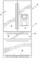
- FIG. 1is a refrigerator appliance in accordance with an exemplary embodiment of the present disclosure.
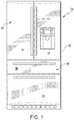
- FIG. 2is a schematic illustration of certain components of a heat pump system positioned in the exemplary refrigerator appliance of FIG. 1 .
- FIG. 3is a schematic illustration of certain components of the heat pump system of FIG. 2 , with a first stage of MCM within a magnetic field and a second stage of MCM out of a magnetic field, in accordance with an exemplary embodiment of the present disclosure.
- FIG. 4is a schematic illustration of certain components of the exemplary heat pump system of FIG. 2 , with the first stage of MCM out of the magnetic field and the second stage of MCM within the magnetic field.
- FIGS. 5 and 6are schematic illustrations of certain components of the heat pump system of FIG. 2 , in accordance with another exemplary embodiment of the present disclosure.
- FIG. 7provides a schematic view of an exemplary caloric heat pump according to another exemplary embodiment of the present subject matter.
- FIG. 8is a schematic diagram illustrating various positions and movements there-between of MCM stages in accordance with an exemplary embodiment of the present disclosure.
- FIG. 9provides a schematic view of certain components of the exemplary caloric heat pump of the heat pump system of FIG. 2 .
- FIG. 10provides a schematic view of certain components of an exemplary caloric heat pump according to another exemplary embodiment of the present subject matter.
- the present subject matteris directed to a caloric heat pump system for heating or cooling an appliance, such as a refrigerator appliance. While described in greater detail below in the context of a magneto-caloric heat pump system, one of skill in the art using the teachings herein will recognize that other suitable caloric materials may be used in a similar manner to heat or cool an appliance, i.e., apply a field, move heat, remove the field, move heat.
- electro-caloric materialheats up and cools down within increasing and decreasing electric fields.
- elasto-caloric materialheats up and cools down when exposed to increasing and decreasing mechanical strain.
- baro-caloric materialheats up and cools down when exposed to increasing and decreasing pressure.
- caloric materialis used broadly herein to encompass materials that undergo heating or cooling when exposed to a changing field from a field generator, where the field generator may be a magnet, an electric field generator, an actuator for applying mechanical stress or pressure, etc.
- refrigerator appliance 10is depicted as an upright refrigerator having a cabinet or casing 12 that defines a number of internal storage compartments or chilled chambers.
- refrigerator appliance 10includes upper fresh-food compartments 14 having doors 16 and lower freezer compartment 18 having upper drawer 20 and lower drawer 22 .
- Drawers 20 , 22are “pull-out” type drawers in that they can be manually moved into and out of freezer compartment 18 on suitable slide mechanisms.
- Refrigerator 10is provided by way of example only. Other configurations for a refrigerator appliance may be used as well including appliances with only freezer compartments, only chilled compartments, or other combinations thereof different from that shown in FIG. 1 .
- heat pump and heat pump system of the present disclosureis not limited to refrigerator appliances and may be used in other applications as well such as e.g., air-conditioning, electronics cooling devices, and others.
- air-conditioninge.g., air-conditioning, electronics cooling devices, and others.
- present disclosuremay also be used to provide for heating applications as well.
- FIG. 2is a schematic view of various components of refrigerator appliance 10 , including refrigeration compartments 30 (e.g., fresh-food compartments 14 and freezer compartment 18 ) and a machinery compartment 40 .
- Refrigeration compartment 30 and machinery compartment 40include a heat pump system 52 having a first cold side heat exchanger 32 positioned in refrigeration compartments 30 for the removal of heat therefrom.
- a heat transfer fluidsuch as e.g., an aqueous solution, flowing within first cold side heat exchanger 32 receives heat from refrigeration compartment 30 thereby cooling contents of refrigeration compartment 30 .
- heat pump system 52also has a second cold side heat exchanger 33 .
- Second cold side heat exchanger 33operates in parallel with first cold side heat exchanger 32 to cool refrigeration compartments 30 , e.g., a respective one of fresh-food compartment 14 and freezer chamber 18 .
- first cold side heat exchanger 32may be positioned at or adjacent fresh-food compartment 14
- air from first cold side heat exchanger 32may cool fresh-food compartment 14
- second cold side heat exchanger 33may be positioned at or adjacent freezer compartment 18 , and air from second cold side heat exchanger 33 may cool freezer compartment 18 .
- the heat transfer fluidflows out of first cold side heat exchanger 32 by line 44 to heat pump 100 .
- the heat transfer fluidreceives additional heat from magneto-caloric material (MCM) in heat pump 100 and carries this heat by line 48 to a third or hot side heat exchanger 34 .
- MCMmagneto-caloric material
- Heatis released to the environment, machinery compartment 40 , and/or other location external to refrigeration compartment 30 using hot side heat exchanger 34 .
- a fan 36may be used to create a flow of air across hot side heat exchanger 34 and thereby improve the rate of heat transfer to the environment.
- a pump or pumpscause the heat transfer fluid to recirculate in heat pump system 52 .
- Motor 28is in mechanical communication with heat pump 100 and is operable to provide relative motion between a field generator and a regenerator housing, as discussed in greater detail below.
- the heat transfer fluidreturns by line 50 to heat pump 100 where, as will be further described below, the heat transfer fluid loses heat to the MCM in heat pump 100 .
- the now colder heat transfer fluidflows by line 46 to first cold side heat exchanger 32 to receive heat from refrigeration compartment 30 and repeat the cycle as just described.
- the heat transfer fluidmay flow to second cold side heat exchanger 33 in the manner described above for first cold side heat exchanger 32 .
- heat transfer fluidflows by line 96 to second cold side heat exchanger 33 from heat pump 100
- heat transfer fluidflows by line 98 to heat pump 100 from second cold side heat exchanger 33 .
- Heat pump system 52is provided by way of example only. Other configurations of heat pump system 52 may be used as well.
- lines 44 , 46 , 48 , 50 , 96 , 98provide fluid communication between the various components of heat pump system 52 but other heat transfer fluid recirculation loops with different lines and connections may also be employed. Still other configurations of heat pump system 52 may be used as well.
- Refrigerator appliance 10also includes features for regulating air flow across first cold side heat exchanger 32 to fresh-food compartment 14 and across second cold side heat exchanger 33 to freezer compartment 18 .
- first cold side heat exchanger 32is positioned within a first heat exchanger compartment 60 that is defined within cabinet 12 , e.g., between fresh-food compartments 14 and freezer compartment 18 .
- Fresh-food compartment 14is contiguous with first heat exchanger compartment 60 through a fresh food duct 62 .
- airmay flow between fresh-food compartment 14 and first heat exchanger compartment 60 via fresh food duct 62 .
- Second cold side heat exchanger 33is positioned within a second heat exchanger compartment 61 that is defined within cabinet 12 , e.g., between fresh-food compartments 14 and freezer compartment 18 .
- Freezer compartment 18is contiguous with second heat exchanger compartment 61 through a freezer duct 64 .
- airmay flow between freezer compartment 18 and second heat exchanger compartment 61 via freezer duct 64 .
- First heat exchanger compartment 61may be separate from second heat exchanger compartment 61 within cabinet 12 .
- fresh food duct 62may be separate from freezer duct 64 within cabinet 12 , in certain exemplary embodiments.
- Refrigerator appliance 10also includes a fresh food fan 66 and a freezer fan 68 .
- Fresh food fan 66may be positioned at or within fresh food duct 62 .
- Fresh food fan 66is operable to force air flow between fresh-food compartment 14 and first heat exchanger compartment 60 through fresh food duct 62 .
- Fresh food fan 66may thus be used to create a flow of air across first cold side heat exchanger 32 and thereby improve the rate of heat transfer.
- Freezer fan 68may be positioned at or within freezer duct 64 .
- Freezer fan 68is operable to force air flow between freezer compartment 18 and second heat exchanger compartment 61 through freezer duct 64 . Freezer fan 68 may thus be used to create a flow of air across second cold side heat exchanger 33 and thereby improve the rate of heat transfer.
- heat pump system 52 and fresh food fan 66allows chilled air from first cold side heat exchanger 32 to cool fresh-food compartment 14 , e.g., to about forty degrees Fahrenheit (40° F.).
- operation of heat pump system 52 and freezer fan 68allows chilled air from second cold side heat exchanger 33 to cool freezer compartment 18 , e.g., to about negative ten degrees Fahrenheit ( ⁇ 10° F.).
- first cold side heat exchanger 32may chill fresh-food compartment 14
- second cold side heat exchanger 33may chill freezer compartment 18 during operation of heat pump system 52 .
- first and second cold side heat exchangers 32 , 33may separately cool fresh-food compartments 14 and freezer compartment 18 .
- FIGS. 3 through 7illustrate various exemplary embodiments of heat pump 100 and components thereof, and the use of the heat pump 100 with heat pump system 52 , in accordance with exemplary embodiments of the present disclosure.
- Heat pump 100 shown in FIGS. 3 through 6may be suitable for use within a linear reciprocating caloric heat pump while heat pump 100 shown in FIG. 7 may be suitable for use within a rotatory caloric heat pump.
- the present subject mattermay be used in or with any suitable heat pump, including linear caloric heat pumps and rotary caloric heat pumps, and the example embodiments of heat pump 100 provided herein are not intended to limit the present subject matter to any particular heat pump arrangement.
- heat pump 100may include a plurality of stages, each of which includes a magneto-caloric material (MCM).
- MCM stagesmay be provided in pairs, each of which may for example include a first stage 130 and a second stage 132 .
- Each stage 130 , 132may include one or more different types of MCM.
- the MCM(s) provided in each stage 130 , 132may be the same or may be different.
- Stages 130 , 132may be disposed within a regenerator housing 140 . Regenerator housing 140 along with stages 130 , 132 and optional insulative materials may collectively be referred to as a regenerator assembly.
- regenerator housing 140may include two stages 130 , 132 . Alternatively, three, four or more stages may be provided in regenerator housing 140 .
- heat pump 100may include a plurality of first stages 130 within regenerator housing 140 , e.g., eight first stages 130 uniformly distributed about a rotation axis of heat pump 100 .
- Each stage 130 , 132may extend between a first end 134 and a second end 136 .
- working fluidalso referred to herein as heat transfer fluid or fluid refrigerant
- heat pump 100includes features for drawing-off or removing the working fluid from the stage 130 , 132 at various locations along a transverse direction T.
- Heat pump 100also includes one or more magnet assemblies (not shown), each of which creates a magnetic field M ( FIG. 8 ), or other suitable field generators.
- the regenerator housing 140 and magnet assembly(s)may be movable relative to each other.
- regenerator housing 140is movable relative to the magnet assembly.
- the magnet assemblymay be movable relative to regenerator housing 140 .
- Such relative movement between regenerator housing 140 and an associated magnet assemblycauses movement of each stage 130 , 132 into the magnetic field M and out of the magnetic field M.
- stages 130 , 132 into the magnetic field Mmay cause the magnetic moments of the material to orient and the MCM to heat (or alternatively cool) as part of the magneto-caloric effect.
- the MCMmay thus cool (or alternatively heat) due to disorder of the magnetic moments of the material.
- regenerator housing 140may be movable linearly between a first position and a second position. In the first position, regenerator housing 140 may be positioned such that first stage 130 disposed within regenerator housing 140 is within the magnetic field M and second stage 132 disposed within regenerator housing 140 is out of the magnetic field M. Notably, being out of the magnetic field M means that second stage 132 is generally or substantially uninfluenced by the magnets and resulting magnetic field M. Accordingly, the MCM of the stage as a whole may not be actively heating (or cooling) as it would if within the magnetic field M (and instead may be actively or passively cooling (or heating) due to such removal of the magnetic field M).
- regenerator housing 140may be positioned such that first stage 130 disposed within regenerator housing 140 is out of the magnetic field M and second stage 132 disposed within regenerator housing 140 is within the magnetic field M.
- regenerator housing 140may also be rotatable such that one portion of stages 130 are within the magnetic field M and the remainder of the stages 130 are out of the magnetic field M in the first position and vice versa in the second position. Movement of a regenerator housing 140 may be caused by operation of motor 28 .
- Motor 28may be in mechanical communication with regenerator housing 140 and configured for linearly or rotatably moving regenerator housing 140 or the magnet assemblies.
- lines 44 , 46 , 48 , 50 , 96 , 98may facilitate the flow of working fluid between heat exchangers 32 , 33 , 34 and heat pump 100 .
- lines 44 , 46 , 48 , 50 , 96 , 98may facilitate the flow of working fluid between heat exchangers 32 , 33 , 34 and stages 130 , 132 of heat pump 100 .
- a line 44e.g., a first cold side working fluid return conduit
- a line 46(e.g., a first cold side working fluid supply conduit) may extend between regenerator housing 140 and first cold side heat exchanger 32 , such that working fluid from regenerator housing 140 flows through line 46 to an inlet of heat exchanger 32 .
- a line 50(e.g., hot side working fluid return conduit) may extend between hot side heat exchanger 34 and regenerator housing 140 , such that working fluid from an outlet of heat exchanger 34 flows through line 50 to regenerator housing 140 .
- a line 48(e.g., hot side working fluid supply conduit) may extend between regenerator housing 140 and hot side heat exchanger 34 , such that working fluid from regenerator housing 140 flows through line 48 to an inlet of heat exchanger 34 .
- a line 96(e.g., a second cold side working fluid return conduit) may extend between second cold side heat exchanger 33 and regenerator housing 140 , such that working fluid from an outlet heat exchanger 33 flows through line 96 to regenerator housing 140 .
- a line 98(e.g., second cold side working fluid supply conduit) may extend between regenerator housing 140 and an inlet second cold side heat exchanger 33 , such that working fluid from regenerator housing 140 flows through line 98 to heat exchanger 33 .
- check valves 190may in some exemplary embodiments be provided on the various lines 44 , 46 , 48 , 50 , 96 , 98 to prevent backflow there-through. Exemplary positions and orientations of check valves 190 on lines 44 , 46 , 96 , 98 are shown in FIGS. 3 through 6 .
- Check valves 190in combination with differential pressures during operation of heat pump 100 , may thus generally prevent flow through the improper flow path when working fluid is being actively flowed through heat pump 100 , e.g., such that working fluid flows through stages 130 , 132 in the manner described below in the context of FIG. 8 .
- check valves 190are positioned on lines 44 , 46 , 96 , 98 to provide the flow of working fluid shown with solid lines 44 , 46 , 96 , 98 in FIG. 3 during the compression stroke of pump 170 and to conversely provide the flow of working fluid shown with solid lines 44 , 46 , 96 , 98 in FIG. 4 during the compression stroke of pump 172 .
- Heat pump system 52may also include a restriction 191 on one of lines 44 , 46 , 96 , 98 . Restriction 191 may assist with balancing working fluid flow between first and second cold side heat exchangers 32 , 33 .
- Heat pump system 52may also include at least one pump, such as pump 170 and/or pump 172 , operable to flow the working fluid through lines 44 , 46 , 48 , 50 , 96 , 98 .
- first and second pumps 170 , 172may be synchronized such that one of first and second pumps 170 , 172 is on a compression stroke while the other of first and second pumps 170 , 172 is on a suction stroke. Such synchronization may assist with maintaining a constant volume of working fluid within heat pump system 52 .
- first pump 170is shown at a bottom dead center position while second pump 172 is shown at a top dead center position.
- FIGS. 170is shown at a bottom dead center position while second pump 172 is shown at a top dead center position.
- first pump 170is shown at the top center position while second pump 172 is shown at the bottom center position.
- first and second pumps 170 , 172may be synchronized to operate completely out of phase with one another.
- first pump 170may also operate continuously to flow working through first stages 130 during rotation of regenerator housing 140 .
- FIG. 8illustrates an exemplary method of the present disclosure using a schematic representation of associated stages 130 , 132 of MCM during dwelling in and movement between the various positions as discussed herein.
- stage 130is fully within magnetic field M, which causes the magnetic moments of the material to orient and the MCM to heat as part of the magneto caloric effect.
- pump 170is activated to actively flow working fluid.
- working fluid in stage 130now heated by the MCM, can travel out of stage 130 and along line 48 to hot side heat exchanger 34 .
- working fluid from first cold side heat exchanger 32flows into stage 130 from line 44 . Because working fluid from first cold side heat exchanger 32 is relatively cooler than the MCM in stage 130 , the MCM will lose heat to the working fluid.
- stage 130is moved from the first position to the second position in the first transition.
- working fluiddwells in the MCM of stage 130 . More specifically, the working fluid does not actively flow through stage 130 .
- stage 130is in the second position and thus out of magnetic field M.
- the absence or lessening of the magnetic fieldis such that the magnetic moments of the material become disordered and the MCM absorbs heat as part of the magnetocaloric effect.
- pump 172is activated to actively flow working fluid.
- working fluid in stage 130now cooled by the MCM, can travel out of stage 130 and along line 46 to first cold side heat exchanger 32 .
- working fluid from hot side heat exchanger 34flows into stage 112 from line 50 when stage 130 is in the second transition. Because working fluid from hot side heat exchanger 34 is relatively warmer than the MCM in stage 130 , the MCM will lose some of its heat to the working fluid.
- the working fluidnow travels along line 46 to first cold side heat exchanger 32 to receive heat and cool refrigeration compartment 30 .
- stage 130is moved from the second position to the first position in the second transition.
- the working fluiddwells in the MCM of stage 130 . More specifically, the working fluid does not actively flow through stage 130 .
- second stage 132With regard to second stage 132 , during step 200 , which corresponds to the first position, second stage 132 is out of magnetic field M. The absence or lessening of the magnetic field is such that the magnetic moments of the material become disordered and the MCM absorbs heat as part of the magneto-caloric effect. Further, pump 170 is activated to actively flow working fluid. As indicated by arrow Q C-OUT , working fluid in stage 132 , now cooled by the MCM, can travel out of stage 132 and along line 46 to first cold side heat exchanger 32 . At the same time, and as indicated by arrow Q C-IN , working fluid from hot side heat exchanger 34 flows into stage 112 from line 50 when stage 132 is in the second transition.
- stage 132is moved from the first position to the second position in the first transition.
- the working fluiddwells in the MCM of stage 132 . More specifically, the working fluid does not actively flow through stage 132 .
- stage 132is in the second position and thus fully within magnetic field M, which causes the magnetic moments of the material to orient and the MCM to heat as part of the magneto caloric effect.
- pump 172is activated to actively flow working fluid.
- working fluid in stage 132now heated by the MCM, can travel out of stage 132 and along line 48 to hot side heat exchanger 34 .
- working fluid from first cold side heat exchanger 32flows into stage 132 from line 44 . Because working fluid from first cold side heat exchanger 32 is relatively cooler than the MCM in stage 132 , the MCM will lose heat to the working fluid.
- stage 132is moved from the second position to the first position in the second transition.
- working fluiddwells in the MCM of stage 132 . More specifically, the working fluid does not actively flow through stage 132 .
- second cold side heat exchanger 33may be configured and operate in the same or similar manner to cool freezer compartment 18 as described above for first cold side heat exchanger 32 to cool fresh-food compartment 14 unless otherwise stated.
- FIG. 9provides a schematic view of certain components of heat pump 100 of heat pump system 52 .
- heat pump 100includes features for drawing working fluid from regenerator housing 140 at a plurality of locations along a length H of first and second stages 130 , 132 .
- the working fluidexits regenerator housing 140 at a first location along the length H of first stage 130 .
- the working fluidexits regenerator housing 140 at a second location (different than the first location) along the length H of first stage 130 when heat pump system 52 operates to cool freezer compartment 18 .
- regenerator housing 140may be configured in a similar manner at second stage 132 to allow multiple working fluid draw location along a length of second stage 132 .
- first stage 130is disposed within regenerator housing 140 .
- first stage 130may have a length H along a longitudinal direction O, e.g., that is parallel to the transverse direction T, within regenerator housing 140 .
- Working fluidis flowable through first stage 130 within regenerator housing 140 .
- Regenerator housing 140is also connected to first cold side heat exchanger 32 such that working fluid is flowable from regenerator housing 140 to first cold side heat exchanger 32 .
- regenerator housing 140includes a first cold side connection 150 . Lines 44 , 46 are connected to regenerator housing 140 at first cold side connection 150 .
- working fluidis flowable from regenerator housing 140 to an inlet of first cold side heat exchanger 32 via line 46 at first cold side connection 150 (also shown in FIGS. 3 through 6 during operation of pumps 170 , 172 and in FIG. 7 during operation of pump 170 ), and working fluid is flowable from an outlet of first cold side heat exchanger 32 to regenerator housing 140 via line 44 at first cold side connection 150 .
- the flow of working fluid through lines 44 , 46 within heat pump system 52may also be seen in FIGS. 3 through 6 during operation of pumps 170 , 172 and in FIG. 7 during operation of pump 170 .
- regenerator housing 140is also connected to second cold side heat exchanger 33 such that working fluid is flowable from regenerator housing 140 to second cold side heat exchanger 33 .
- regenerator housing 140includes a second cold side connection 154 .
- Lines 96 , 98are connected to regenerator housing 140 at second cold side connection 154 .
- working fluidis flowable from regenerator housing 140 to an inlet of second cold side heat exchanger 33 via line 98 at second cold side connection 154
- working fluidis flowable from an outlet of second cold side heat exchanger 33 to regenerator housing 140 via line 96 at second cold side connection 154 .
- lines 96 , 98may be in parallel with lines 44 , 46 .
- the flow of working fluid through lines 96 , 98 within heat pump system 52may also be seen in FIGS. 3 through 6 during operation of pumps 170 , 172 and in FIG. 7 during operation of pump 170 .
- Regenerator housing 140is also connected to hot side heat exchanger 34 such that working fluid is flowable between regenerator housing 140 and hot side heat exchanger 34 .
- regenerator housing 140has a hot side connection 152 .
- Lines 48 , 50are connected to regenerator housing 140 at hot side connection 152 .
- working fluidis flowable from regenerator housing 140 to an inlet of hot side heat exchanger 34 via line 48 at hot side connection 152
- working fluidis flowable from an outlet of hot side heat exchanger 34 to regenerator housing 140 via line 50 at hot side connection 152 .
- the flow of working fluid through lines 48 , 50 within heat pump system 52may also be seen in FIGS. 3 through 6 during operation of pumps 170 , 172 and in FIG. 7 during operation of pump 170 .
- Hot side connection 152is spaced from first and second cold side connections 150 , 154 on regenerator housing 140 , e.g., along the longitudinal direction O.
- hot side connection 152may be positioned at first end portion 144 of regenerator housing 140
- second cold side connection 154may be positioned at second end portion 146 of regenerator housing 140 .
- First cold side connection 150may be positioned between hot side connection 152 and second cold side connection 154 , e.g., along the longitudinal direction O.
- first cold side connection 150may draw working fluid from regenerator housing 140 at a different location along the length H of first stage 130 relative to second cold side connection 154 .
- the working fluidexits regenerator housing 140 at the first cold side connection 150 when heat pump system 52 operates to cool fresh-food compartment 14
- the working fluidexits regenerator housing 140 at the second cold side connection 154 when heat pump system 52 operates to cool freezer compartment 18 .
- First cold side connection 150is closer to hot side connection 152 than second cold side connection 154 , e.g., along the longitudinal direction O.
- the working fluidmay flow through less of the length H of first stage 130 to first cold side connection 150 compared to second cold side connection 154 .
- cooling of the working fluid by first stage 130may be regulated.
- first stage 130may reduce the temperature of the working fluid more when the working fluid exits regenerator housing 140 at second cold side connection 154 compared to when the working fluid exits regenerator housing 140 at first cold side connection 150 .
- additional cold side connectionsmay be positioned at any other suitable location in alternative exemplary embodiments. For example, if refrigerator appliance 10 has a deli tray, an icemaker, a cold water dispenser, a quick freezer feature, etc., a respective cold side connection may be provided for each additional component of refrigerator appliance.
- the multiple cold side connections on regenerator housing 140allows working fluid to be pulled-off at multiple locations when cooling the first and second cold side heat exchangers 32 , 33 .
- each compartmentmay be cooled to a respective set temperature.
- heat pump system 52may utilize multiple cold side heat exchangers 32 , 33 to cool multiple refrigeration compartments 30
- the first and second cold side connections 150 , 154 on regenerator housing 140allow working fluid to be pulled-off at multiple locations to cold side heat exchangers 32 , 33 .
- each compartmentmay be cooled to a respective set temperature.
- heat pump system 52may theoretically be fifteen percent more efficient than known dual heat exchanger systems. It will be understood that only one of fresh-food compartment 14 and freezer compartment 18 may be actively cooled by heat pump system 52 at any particular time. The speed and/or the duty cycle of heat pump 100 can be programmatically matched to the required load of each compartment with minimal effect on efficiency. Alternatively, both fresh-food compartment 14 and freezer compartment 18 may be actively cooled by heat pump system 52 at any particular time.
- FIG. 10provides a schematic view of certain components of heat pump 100 according to another exemplary embodiment of the present subject matter.
- Heat pump 100includes similar component and operates in a similar manner to that descried above.
- first stage 130has a first section 192 and a second section 194 .
- First and second sections 192 , 194 of first stage 130are spaced or separate, e.g., along the longitudinal direction O.
- first section 192may be positioned at first end portion 144 of regenerator housing 140
- second section 194may be positioned at second end portion 146 of regenerator housing 140 .
- First cold side connection 150may be positioned between first and second sections 192 , 194 .
- first stage 130may be continuous between first and second sections 192 , 194 or first and second sections 192 , 194 may be separated by a gap, e.g., at first cold side connection 150 .
- First and second sections 192 , 194are differently sized and/or formed.
- first and second sections 192 , 194may have different cross-sectional areas, e.g., in parallel planes that are perpendicular to the longitudinal direction O.
- first section 192may have a larger cross-sectional area than second section 194 , e.g., along the longitudinal direction O.
- first and second sections 192 , 194may have different lengths, e.g., along the longitudinal direction O.
- first section 192may be longer than second section 194 , e.g., along the longitudinal direction O.
- first section 192may be larger than second section 194 , e.g., such that a temperature differential of working fluid flowing through first section 192 is greater than through second section 194 .
- the size of first section 192e.g., cross-sectional area, length, etc.
- Second section 194may also be sized to match a flow of working fluid through second section 194 .
- First and second sections 192 , 194may be common caloric materials or may be different caloric materials, e.g., such that a temperature gradient of working fluid is different within first and second sections 192 , 194 .
- regenerator housing 140may have a joint 196 between first and second sections 192 , 194 .
- Joint 196is tapered.
- joint 196may taper or converge from first section 192 to first cold side connection 150
- joint 196may also taper or converge from second section 194 to first cold side connection 150 .
- Such taperingencourages mixing of returning working fluid at first cold side connection 150 and reduces dead volume within regenerator housing 140 .
Landscapes
- Engineering & Computer Science (AREA)
- Physics & Mathematics (AREA)
- Mechanical Engineering (AREA)
- Thermal Sciences (AREA)
- General Engineering & Computer Science (AREA)
- Chemical & Material Sciences (AREA)
- Combustion & Propulsion (AREA)
- Devices That Are Associated With Refrigeration Equipment (AREA)
Abstract
Description
Claims (13)
Priority Applications (1)
| Application Number | Priority Date | Filing Date | Title |
|---|---|---|---|
| US15/471,226US11009282B2 (en) | 2017-03-28 | 2017-03-28 | Refrigerator appliance with a caloric heat pump |
Applications Claiming Priority (1)
| Application Number | Priority Date | Filing Date | Title |
|---|---|---|---|
| US15/471,226US11009282B2 (en) | 2017-03-28 | 2017-03-28 | Refrigerator appliance with a caloric heat pump |
Publications (2)
| Publication Number | Publication Date |
|---|---|
| US20180283764A1 US20180283764A1 (en) | 2018-10-04 |
| US11009282B2true US11009282B2 (en) | 2021-05-18 |
Family
ID=63672535
Family Applications (1)
| Application Number | Title | Priority Date | Filing Date |
|---|---|---|---|
| US15/471,226Active2038-05-02US11009282B2 (en) | 2017-03-28 | 2017-03-28 | Refrigerator appliance with a caloric heat pump |
Country Status (1)
| Country | Link |
|---|---|
| US (1) | US11009282B2 (en) |
Families Citing this family (1)
| Publication number | Priority date | Publication date | Assignee | Title |
|---|---|---|---|---|
| US11193697B2 (en)* | 2019-01-08 | 2021-12-07 | Haier Us Appliance Solutions, Inc. | Fan speed control method for caloric heat pump systems |
Citations (296)
| Publication number | Priority date | Publication date | Assignee | Title |
|---|---|---|---|---|
| US668560A (en) | 1900-11-08 | 1901-02-19 | Eugen Fuellner | Apparatus for collecting pulp from waste waters of paper or cellulose works. |
| US1985455A (en) | 1933-02-06 | 1934-12-25 | Gilbert H Mosby | Container for carbonated liquids |
| DE804694C (en) | 1948-10-02 | 1951-04-26 | Deutsche Edelstahlwerke Ag | Permanent magnetic circle |
| US2671929A (en) | 1949-11-03 | 1954-03-16 | American Viscose Corp | Apparatus for producing filaments of uneven denier |
| US2765633A (en) | 1950-08-09 | 1956-10-09 | Muffly Glenn | Defrosting of evaporator |
| DE1514388A1 (en) | 1965-01-26 | 1969-06-19 | Spodig Heinrich | Cylindrical body with permanently magnetically excited circumferential surface |
| US3618265A (en) | 1969-01-08 | 1971-11-09 | Remington Arms Co Inc | Finishing machine for metal surfaces |
| US3816029A (en) | 1972-10-03 | 1974-06-11 | Duriron Co | Pumping unit for constant pulseless flow |
| US3844341A (en) | 1972-05-22 | 1974-10-29 | Us Navy | Rotatable finned heat transfer device |
| US3956076A (en) | 1973-01-05 | 1976-05-11 | Urban Research & Development Corporation | Pyrolytic treatment of solid waste materials to form ceramic prills |
| US4037427A (en) | 1971-05-21 | 1977-07-26 | Kramer Doris S | Refrigeration evaporators with ice detectors |
| US4102655A (en) | 1977-05-02 | 1978-07-25 | Cobe Laboratories, Inc. | Bubble trap |
| US4107935A (en) | 1977-03-10 | 1978-08-22 | The United States Of America As Represented By The United States Department Of Energy | High temperature refrigerator |
| US4197709A (en) | 1978-06-09 | 1980-04-15 | Hochstein Peter A | Thermal energy scavenger (stress limiter) |
| US4200680A (en) | 1974-06-13 | 1980-04-29 | Fuji Photo Film Co., Ltd. | Process for preparing magnetic iron oxide and magnetic iron oxide produced thereby |
| US4259843A (en) | 1979-10-09 | 1981-04-07 | Cromemco Inc. | Isolation chamber for electronic devices |
| US4332135A (en) | 1981-01-27 | 1982-06-01 | The United States Of America As Respresented By The United States Department Of Energy | Active magnetic regenerator |
| US4408463A (en) | 1982-01-20 | 1983-10-11 | Barclay John A | Wheel-type magnetic refrigerator |
| JPS597023B2 (en) | 1974-07-30 | 1984-02-16 | ロ−ベルト ボツシユ ゲゼルシヤフト ミツト ベシユレンクテル ハフツング | Fuel metering device for internal combustion engines |
| JPS59232922A (en) | 1983-06-15 | 1984-12-27 | Dainippon Ink & Chem Inc | Manufacture of spindle-shaped goethite having high axial ratio |
| US4507928A (en) | 1984-03-09 | 1985-04-02 | The United States Of America As Represented By The Administrator Of The National Aeronautics And Space Administration | Reciprocating magnetic refrigerator employing tandem porous matrices within a reciprocating displacer |
| US4507927A (en) | 1983-05-26 | 1985-04-02 | The United States Of America As Represented By The United States Department Of Energy | Low-temperature magnetic refrigerator |
| US4549155A (en) | 1982-09-20 | 1985-10-22 | The United States Of America As Represented By The United States Department Of Energy | Permanent magnet multipole with adjustable strength |
| US4554790A (en) | 1984-02-13 | 1985-11-26 | Kabushiki Kaisha Toshiba | Magnetic refrigerating apparatus |
| US4557228A (en) | 1981-12-30 | 1985-12-10 | Samodovitz Arthur J | Piston and spring powered engine |
| EP0187078A1 (en) | 1984-12-18 | 1986-07-09 | Commissariat A L'energie Atomique | Cooling or heat pumping device |
| US4599866A (en) | 1984-06-05 | 1986-07-15 | Kabushiki Kaisha Toshiba | Magnetic refrigerator |
| US4625519A (en) | 1984-04-20 | 1986-12-02 | Hitachi, Ltd. | Rotary magnetic refrigerator |
| US4642994A (en) | 1985-10-25 | 1987-02-17 | The United States Of America As Represented By The United States Department Of Energy | Magnetic refrigeration apparatus with heat pipes |
| JPS6212955B2 (en) | 1981-05-15 | 1987-03-23 | Penshirubania Gurasu Sando Corp | |
| US4735062A (en) | 1987-06-22 | 1988-04-05 | General Electric Company | Refrigerator with anti-sweat hot liquid loop |
| US4741175A (en) | 1987-03-17 | 1988-05-03 | General Electric Company | Auto defrost refrigerator |
| US4785636A (en) | 1986-07-11 | 1988-11-22 | Hitachi, Ltd. | Magnetic refrigerator and refrigeration method |
| US4796430A (en) | 1987-08-14 | 1989-01-10 | Cryodynamics, Inc. | Cam drive for cryogenic refrigerator |
| US5062471A (en) | 1988-05-26 | 1991-11-05 | University Of Florida | Heat transfer system without mass transfer |
| US5091361A (en) | 1990-07-03 | 1992-02-25 | Hed Aharon Z | Magnetic heat pumps using the inverse magnetocaloric effect |
| US5156003A (en) | 1990-11-08 | 1992-10-20 | Koatsu Gas Kogyo Co., Ltd. | Magnetic refrigerator |
| US5190447A (en) | 1992-03-23 | 1993-03-02 | The United States Of America As Represented By The Secretary Of The Navy | Hydraulic pump with integral electric motor |
| US5249424A (en) | 1992-06-05 | 1993-10-05 | Astronautics Corporation Of America | Active magnetic regenerator method and apparatus |
| US5336421A (en) | 1990-11-22 | 1994-08-09 | Toda Kogyo Corp. | Spinel-type spherical, black iron oxide particles and process for the producing the same |
| US5351791A (en) | 1990-05-18 | 1994-10-04 | Nachum Rosenzweig | Device and method for absorbing impact energy |
| US5465781A (en) | 1992-10-29 | 1995-11-14 | Elastek, Inc. | Elastomer bed |
| JPH08166182A (en) | 1994-12-13 | 1996-06-25 | Sharp Corp | Heat exchange unit and refrigeration equipment including the same |
| US5599177A (en) | 1993-04-22 | 1997-02-04 | Binks Manufacturing Company | Precision metered multiple fluid pumping system |
| US5661895A (en) | 1995-07-25 | 1997-09-02 | Outboard Marine Corporatin | Method of controlling the magnetic gap length and the initial stroke length of a pressure surge fuel pump |
| US5718570A (en) | 1995-03-20 | 1998-02-17 | Micropump Corporation | Rotary control valve for a piston pump |
| US5934078A (en) | 1998-02-03 | 1999-08-10 | Astronautics Corporation Of America | Reciprocating active magnetic regenerator refrigeration apparatus |
| WO2001033145A1 (en) | 1999-11-02 | 2001-05-10 | Abb Ab | A plant for extracting and a method for liquefying a gas |
| US6332323B1 (en) | 2000-02-25 | 2001-12-25 | 586925 B.C. Inc. | Heat transfer apparatus and method employing active regenerative cycle |
| WO2002012800A1 (en) | 2000-08-09 | 2002-02-14 | Astronautics Corporation Of America | Rotating bed magnetic refrigeration apparatus |
| US20020040583A1 (en) | 2000-05-05 | 2002-04-11 | Barclay John A. | Apparatus and methods for cooling and liquefying a fluid using magnetic refrigeration |
| US20020066368A1 (en) | 1998-12-31 | 2002-06-06 | Hexablock, Inc. | Magneto adsorbent |
| US20020087120A1 (en) | 1999-04-30 | 2002-07-04 | Medtronic, Inc. | Passive flow control devices for implantable pumps |
| US6423255B1 (en) | 2000-03-24 | 2002-07-23 | Rainer Hoechsmann | Method for manufacturing a structural part by deposition technique |
| US6446441B1 (en) | 2001-08-28 | 2002-09-10 | William G. Dean | Magnetic refrigerator |
| JP2002315243A (en) | 2001-04-13 | 2002-10-25 | Hitachi Ltd | Permanent magnet type rotating electric machine |
| US20030010054A1 (en) | 2001-07-13 | 2003-01-16 | Esch Willy Van | Ice maker cooler |
| US6517744B1 (en) | 1999-11-16 | 2003-02-11 | Jsr Corporation | Curing composition for forming a heat-conductive sheet, heat-conductive sheet, production thereof and heat sink structure |
| WO2003016794A1 (en) | 2001-08-17 | 2003-02-27 | Abb Ab | A fluid handling system |
| US20030051774A1 (en) | 2001-03-27 | 2003-03-20 | Akiko Saito | Magnetic material |
| US6588215B1 (en) | 2002-04-19 | 2003-07-08 | International Business Machines Corporation | Apparatus and methods for performing switching in magnetic refrigeration systems using inductively coupled thermoelectric switches |
| US6612816B1 (en) | 1998-10-20 | 2003-09-02 | Pierre Vanden Brande | Molecular pump |
| US6668560B2 (en) | 2001-12-12 | 2003-12-30 | Astronautics Corporation Of America | Rotating magnet magnetic refrigerator |
| US20040093877A1 (en) | 2001-07-16 | 2004-05-20 | Hirofumi Wada | Magnetic refrigerant material, regenerator and magnetic refrigerator |
| WO2004068512A1 (en) | 2003-01-29 | 2004-08-12 | Stichting Voor De Technische Wetenschappen | A magnetic material with cooling capacity, a method for the manufacturing thereof and use of such material |
| US20040182086A1 (en) | 2003-03-20 | 2004-09-23 | Hsu-Cheng Chiang | Magnetocaloric refrigeration device |
| US20040187803A1 (en) | 2003-03-28 | 2004-09-30 | Aron Regev | Rotary vane motor |
| US20040187510A1 (en) | 2003-03-29 | 2004-09-30 | Samsung Electronics Co., Ltd. | Refrigerator |
| US20040250550A1 (en) | 2001-07-31 | 2004-12-16 | Stichting Voor De Technische Wetenschappen | Material for magnetic refrigeration preparation and application |
| US6840302B1 (en) | 1999-04-21 | 2005-01-11 | Kobe Steel, Ltd. | Method and apparatus for injection molding light metal alloy |
| US20050017394A1 (en) | 2003-06-16 | 2005-01-27 | Voxeljet Gmbh | Methods and systems for the manufacture of layered three-dimensional forms |
| US20050046533A1 (en) | 2003-08-29 | 2005-03-03 | Jeremy Chell | Permanent magnet assembly |
| US20050109490A1 (en) | 2001-12-12 | 2005-05-26 | Steve Harmon | Energy efficient heat pump systems for water heating and airconditioning |
| US6915647B2 (en) | 2003-05-21 | 2005-07-12 | Hoshizaki Denki Kabushiki Kaisha | Abnormality detecting device of auger-type ice making machine and abnormality detecting method thereof |
| US6935121B2 (en) | 2003-12-04 | 2005-08-30 | Industrial Technology Research Institute | Reciprocating and rotary magnetic refrigeration apparatus |
| US20050217278A1 (en) | 2004-03-31 | 2005-10-06 | Mongia Rajiv K | Apparatus to use a magnetic based refrigerator in mobile computing device |
| US20050263357A1 (en) | 2002-05-28 | 2005-12-01 | Isuzu Motors Limited | Eddy current deceleration device |
| US6971245B2 (en) | 2003-08-08 | 2005-12-06 | Hoshizaki Denki Kabushiki Kaisha | Auger type ice making machine |
| US20050274676A1 (en) | 2004-06-10 | 2005-12-15 | Mukesh Kumar | Deionization filter for fuel cell vehicle coolant |
| US20060130518A1 (en) | 2004-12-22 | 2006-06-22 | Samsung Electronics, Co. Ltd. Of Korea | Refrigerator and manufacturing method of the same |
| US20060231163A1 (en) | 2005-03-31 | 2006-10-19 | Satoshi Hirosawa | Magnetic alloy material and method of making the magnetic alloy material |
| US7148777B2 (en) | 2004-02-03 | 2006-12-12 | Astronautics Corporation Of America | Permanent magnet assembly |
| US20060279391A1 (en) | 2005-06-10 | 2006-12-14 | Beijing Taijie Magneto-Electrical Institute | Permanent magnet, magnetic device for use in MRI including the same, and manufacturing processes thereof |
| WO2007036729A1 (en) | 2005-09-29 | 2007-04-05 | Cambridge Enterprise Limited | Magnetocaloric refrigerant |
| CN1977131A (en) | 2003-10-23 | 2007-06-06 | 制冷技术应用公司 | Device for generation of a thermal flow of magneto-calorific material |
| JP2007147136A (en) | 2005-11-25 | 2007-06-14 | Toshiba Corp | Magnetic refrigerator |
| WO2007086638A1 (en) | 2006-01-27 | 2007-08-02 | Daewoo Electronics Corperation | Active magnetic refrigerator |
| US20070220901A1 (en) | 2006-03-27 | 2007-09-27 | Kabushiki Kaisha Toshiba | Magnetic refrigeration material and magnetic refrigeration device |
| JP2007291437A (en) | 2006-04-24 | 2007-11-08 | Hitachi Metals Ltd | Sintered compact for magnetic refrigeration working bed, and its manufacturing method |
| US7297270B2 (en) | 2003-04-04 | 2007-11-20 | Chf Solutions, Inc. | Hollow fiber filter for extracorporeal blood circuit |
| US7313926B2 (en) | 2005-01-18 | 2008-01-01 | Rexorce Thermionics, Inc. | High efficiency absorption heat pump and methods of use |
| JP2008051412A (en) | 2006-08-24 | 2008-03-06 | Chubu Electric Power Co Inc | Magnetic refrigeration equipment |
| US20080223853A1 (en) | 2004-03-30 | 2008-09-18 | Christian Muller | Heat Generator Comprising a Magneto-Caloric Material and Thermie Generating Method |
| US20080236175A1 (en) | 2007-03-30 | 2008-10-02 | Pedro Chaparro Monferrer | Microarchitecture control for thermoelectric cooling |
| US20080236171A1 (en) | 2006-09-28 | 2008-10-02 | Kabushiki Kaisha Toshiba | Magnetic refrigerating device and magnetic refrigerating method |
| CN101280983A (en) | 2007-12-25 | 2008-10-08 | 包头稀土研究院 | Room Temperature Magnetic Refrigeration System and Its Application |
| US20080303375A1 (en) | 2007-06-08 | 2008-12-11 | David Reginald Carver | Device and Method for Converting Thermal Energy into Electrical Energy |
| US7481064B2 (en) | 2002-12-24 | 2009-01-27 | Haute Ecole D'ingenierie Et De Gestion Du Canton De Vaud (Heig-Vd) | Method and device for continuous generation of cold and heat by means of the magneto-calorific effect |
| US20090032223A1 (en) | 2007-08-01 | 2009-02-05 | Harris Corporation | Non-Contacting Thermal Rotary Joint |
| WO2009024412A1 (en) | 2007-08-17 | 2009-02-26 | The Technical University Of Denmark | A refrigeration device and a method of refrigerating |
| US20090091411A1 (en) | 2007-10-04 | 2009-04-09 | Hussmann Corporation | Permanent magnet device |
| EP2071255A1 (en) | 2007-12-14 | 2009-06-17 | Liebherr-Hausgeräte Ochsenhausen GmbH | Refrigeration and/or freezer device with a magneto caloric cooler |
| US7552592B2 (en) | 2005-11-30 | 2009-06-30 | Kabushiki Kaisha Toshiba | Magnetic refrigerator |
| CN101495818A (en) | 2006-07-24 | 2009-07-29 | 制冷技术应用股份有限公司 | Magnetocaloric thermal generator |
| WO2009098391A1 (en) | 2007-12-04 | 2009-08-13 | Cooltech Applications S.A.S. | Magnetocaloric generator |
| US20090217674A1 (en) | 2008-02-28 | 2009-09-03 | Shiori Kaji | Magnetic material for magnetic refrigeration apparatus, amr bed, and magnetic refrigeration apparatus |
| US20090236930A1 (en) | 2005-04-28 | 2009-09-24 | Denso Corporation | Motor and control unit thereof |
| EP2108904A1 (en) | 2008-04-07 | 2009-10-14 | Haute Ecole d'Ingénierie et de Gestion du Canton de Vaud (HEIG-VD) | A magnetocaloric device, especially a magnetic refrigerator, a heat pump or a power generator |
| US20090266083A1 (en) | 2006-07-10 | 2009-10-29 | Daewoo Electronics Corporation | Rotation type regenerator and magnetic refrigerator using the regenerator |
| US20090308080A1 (en) | 2008-06-16 | 2009-12-17 | Hyundai Motor Company | Air Conditioning System |
| US20090314860A1 (en) | 2008-06-20 | 2009-12-24 | Caterpillar Inc. | Z orifice feature for mechanically actuated fuel injector |
| US20100000228A1 (en)* | 2006-12-01 | 2010-01-07 | Matthias Wiest | Refrigerator unit and/or freezer unit |
| US7644588B2 (en) | 2005-12-21 | 2010-01-12 | Daewoo Electronics Corporation | Magnetic refrigerator |
| FR2935468A1 (en) | 2009-08-25 | 2010-03-05 | Cooltech Applications | Magnetocaloric thermal generator for generating heat energy in e.g. domestic application, has compensation unit taking initial form during returning of one of circulating units at end of hot or cold chamber away from magnetocaloric element |
| US20100058775A1 (en) | 2008-09-04 | 2010-03-11 | Kabushiki Kaisha Toshiba | Magnetically refrigerating magnetic material, magnetic refrigeration apparatus, and magnetic refrigeration system |
| US20100071383A1 (en) | 2008-09-24 | 2010-03-25 | Hussmann Corporation | Magnetic refrigeration device |
| US20100116471A1 (en) | 2007-12-27 | 2010-05-13 | Georg Werner Reppel | Composite article with magnetocalorically active material and method for its production |
| JP2010112606A (en) | 2008-11-05 | 2010-05-20 | Toshiba Corp | Magnetic temperature regulator |
| US20100122488A1 (en) | 2007-05-15 | 2010-05-20 | Toshiharu Fukai | Oil emulsion |
| US20100150747A1 (en) | 2008-12-12 | 2010-06-17 | Caterpillar Inc. | Pump having pulsation-reducing engagement surface |
| US20100162747A1 (en) | 2008-12-31 | 2010-07-01 | Timothy Allen Hamel | Refrigerator with a convertible compartment |
| CN101788207A (en) | 2009-12-29 | 2010-07-28 | 华南理工大学 | Microchannel enhanced heat exchange system of rotary room-temperature magnetic refrigerator and heat transfer method thereof |
| EP2215955A1 (en) | 2009-02-09 | 2010-08-11 | V-Zug AG | Dishwasher with heat pump |
| US20100209084A1 (en) | 2009-02-13 | 2010-08-19 | General Electric Company | Residential heat pump water heater |
| CN101842647A (en) | 2007-10-30 | 2010-09-22 | 制冷技术应用股份有限公司 | Thermal generator with magneto-caloric material |
| WO2010119591A1 (en) | 2009-04-17 | 2010-10-21 | シャープ株式会社 | Freezer-refrigerator and cooling storage unit |
| US20100276627A1 (en) | 2007-04-05 | 2010-11-04 | Universite Henri Poincare Nancy 1 | New intermetallic compounds, their use and a process for preparing the same |
| US20100303917A1 (en) | 2007-10-25 | 2010-12-02 | Revalesio Corporation | Compositions and methods for treating cystic fibrosis |
| US7863789B2 (en) | 2005-10-19 | 2011-01-04 | Dura-Trac Motors, Inc. | Brushless permanent magnet motor/generator with axial rotor decoupling to eliminate magnet induced torque losses |
| US20110000206A1 (en) | 2007-01-24 | 2011-01-06 | Torok Aprad | Progressive thermodynamic system |
| CN101979937A (en) | 2010-10-15 | 2011-02-23 | 西安交通大学 | A rotary magnetic refrigeration device and its application |
| US20110042608A1 (en) | 2008-04-28 | 2011-02-24 | Basf Se | Open-celled, porous shaped body for heat exchangers |
| US20110048690A1 (en) | 2008-05-16 | 2011-03-03 | Vacuumschmelze Gmbh & Co. Kg | Article for Magnetic Heat Exchange and Method for Manufacturing an Article for Magnetic Heat Exchange |
| US20110048031A1 (en) | 2009-08-28 | 2011-03-03 | General Electric Company | Magneto-caloric regenerator system and method |
| US20110058795A1 (en) | 2009-09-08 | 2011-03-10 | Rheem Manufacturing Company | Heat pump water heater and associated control system |
| US20110061398A1 (en) | 2009-09-17 | 2011-03-17 | Cheng-Yen Shih | Magnetic refrigerator |
| US20110062821A1 (en) | 2009-09-17 | 2011-03-17 | Chang Shao Hsiung | Heat-power conversion magnetism devices |
| CN201772566U (en) | 2010-07-02 | 2011-03-23 | 海信科龙电器股份有限公司 | A fan blade heat exchanger |
| WO2011034594A1 (en) | 2009-09-17 | 2011-03-24 | Materials And Electrochemical Research (Mer) Corporation | Flow-synchronous field motion refrigeration |
| US20110082026A1 (en) | 2009-09-16 | 2011-04-07 | Sumitomo Chemical Company, Limited | Photocatalyst composite and photocatalytic functional product using the same |
| US20110094243A1 (en) | 2009-08-10 | 2011-04-28 | Basf Se | Magneto-caloric heat pump with the use of a cascade of magneto-caloric materials |
| US7938632B2 (en) | 2003-12-20 | 2011-05-10 | Itw Limited | Piston pump with cam follower arrangement |
| EP2322072A2 (en) | 2011-02-18 | 2011-05-18 | V-Zug AG | Dishwasher with a latent heat reservoir |
| US20110129363A1 (en) | 2007-08-08 | 2011-06-02 | Toyota Jidosha Kabushiki Kaisha | Fuel pump |
| US20110154832A1 (en) | 2009-12-29 | 2011-06-30 | General Electric Company | Composition and method for producing the same |
| US20110162388A1 (en) | 2010-01-05 | 2011-07-07 | General Electric Company | Magnetocaloric device |
| US20110173993A1 (en) | 2008-09-25 | 2011-07-21 | Cooltech Applications S.A.S. | Magnetocaloric element |
| US20110182086A1 (en) | 2007-12-07 | 2011-07-28 | Qualcomm Incorporated | Light illumination of displays with front light guide and coupling elements |
| US20110192836A1 (en) | 2008-10-14 | 2011-08-11 | Cooltech Applications | Thermal generator with magnetocaloric material |
| CN102165615A (en) | 2008-09-25 | 2011-08-24 | 制冷技术应用股份有限公司 | Thermal generator with magnetocaloric material |
| US20110218921A1 (en) | 2010-03-05 | 2011-09-08 | Oracle International Corporation | Notify/inquire fulfillment systems before processing change requests for adjusting long running order management fulfillment processes in a distributed order orchestration system |
| US8061147B2 (en) | 2005-01-12 | 2011-11-22 | The Technical University Of Denmark | Magnetic regenerator, a method of making a magnetic regenerator, a method of making an active magnetic refrigerator and an active magnetic refrigerator |
| US20110284196A1 (en) | 2008-11-24 | 2011-11-24 | Mariofelice Zanadi | Heat exchanger with an improved connector for an air conditioning circuit of a motor vehicle |
| US8069662B1 (en) | 2008-10-30 | 2011-12-06 | Robert Bosch Gmbh | Eccentric cam brake booster |
| WO2011152179A1 (en) | 2010-06-02 | 2011-12-08 | ピーエム技研株式会社 | Magnet roller |
| US20110302931A1 (en) | 2010-06-11 | 2011-12-15 | Sohn Chun Shig | Cooling device |
| US20110308258A1 (en) | 2009-01-30 | 2011-12-22 | Technical University Of Denmark | Parallel magnetic refrigerator assembly and a method of refrigerating |
| US20110314836A1 (en) | 2009-03-20 | 2011-12-29 | Cooltech Applications S.A.S. | Magnetocaloric heat generator |
| KR101100301B1 (en) | 2004-01-29 | 2011-12-30 | 엘지전자 주식회사 | Cryogenic freezer |
| US8099964B2 (en) | 2006-09-28 | 2012-01-24 | Kabushiki Kaisha Toshiba | Magnetic refrigerating device and magnetic refrigerating method |
| CN102345942A (en) | 2010-07-28 | 2012-02-08 | 通用电气公司 | Cooling system of an electromagnet assembly |
| US20120031108A1 (en) | 2010-08-05 | 2012-02-09 | Tadahiko Kobayashi | Magnetic refrigerating device and magnetic refrigerating system |
| US20120033002A1 (en) | 2009-03-24 | 2012-02-09 | Basf Se | Printing method for producing thermomagnetic form bodies for heat exchangers |
| US20120036868A1 (en) | 2010-08-16 | 2012-02-16 | Cooltech Applications S.A.S | Magnetocaloric thermal applicance |
| US20120045698A1 (en) | 2005-06-23 | 2012-02-23 | Mitsubishi Chemical Corporation | Non-aqueous liquid electrolyte and non-aqueous liquid electrolyte secondary battery using the same |
| US20120060526A1 (en) | 2010-12-01 | 2012-03-15 | General Electric Company | Refrigerator energy and temperature control |
| US8191375B2 (en) | 2005-12-13 | 2012-06-05 | Haute Ecole d'Ingenierie et de Gestion du Canton de Vaud ( Heig-VD) | Device for generating cold and heat by a magneto-calorific effect |
| US8216396B2 (en) | 2003-05-02 | 2012-07-10 | W. L. Gore & Associates, Inc. | Shape memory alloy articles with improved fatigue performance and methods therefor |
| US20120222428A1 (en) | 2009-11-11 | 2012-09-06 | Serdar Celik | Combined-loop magnetic refrigeration system |
| CN202432596U (en) | 2012-02-09 | 2012-09-12 | 辽宁鑫源重工有限公司 | Heating system of magnetic heat pump |
| US20120267090A1 (en) | 2011-04-20 | 2012-10-25 | Ezekiel Kruglick | Heterogeneous Electrocaloric Effect Heat Transfer Device |
| US20120266591A1 (en) | 2011-04-25 | 2012-10-25 | Denso Coprporation | Thermo-magnetic engine apparatus and reversible thermo-magnetic cycle apparatus |
| US20120266607A1 (en) | 2011-04-25 | 2012-10-25 | Denso Corporation | Magneto-caloric effect type heat pump apparatus |
| US20120272666A1 (en) | 2011-04-28 | 2012-11-01 | Denso Corporation | Magnetic heat pump system |
| US20120272665A1 (en) | 2011-04-26 | 2012-11-01 | Denso Corporation | Magnetic heat pump apparatus |
| US20120285179A1 (en) | 2011-05-13 | 2012-11-15 | Denso Corporation | Thermo-magnetic cycle apparatus |
| US20120291453A1 (en) | 2011-05-17 | 2012-11-22 | Denso Corporation | Magnetic heat pump apparatus |
| US20130020529A1 (en) | 2011-07-22 | 2013-01-24 | Delta Electronics, Inc. | Method for manufacturing magneto caloric device |
| US20130019610A1 (en) | 2011-07-19 | 2013-01-24 | Zimm Carl B | System and method for reverse degradation of a magnetocaloric material |
| US8378769B2 (en) | 2010-08-16 | 2013-02-19 | Cooltech Applications, S.A.S. | Magnetic field generator for a magnetocaloric thermal appliance and process for assembling such generator |
| KR101238234B1 (en) | 2011-11-18 | 2013-03-04 | 한국과학기술원 | Active magnetic refrigerator for optimum flow rate adjustment |
| US20130104568A1 (en) | 2011-10-31 | 2013-05-02 | Delta Electronics, Inc. | Magnetic cooling device and magnetocaloric module thereof |
| US20130106116A1 (en) | 2011-10-28 | 2013-05-02 | Chung-Jung Kuo | Thermomagnetic generator |
| CN103090583A (en) | 2011-10-31 | 2013-05-08 | 台达电子工业股份有限公司 | Magnetic refrigeration device and magnetic heating module thereof |
| US20130145573A1 (en) | 2011-12-09 | 2013-06-13 | Saeed Bizhanzadeh | Vortex pneumatic conveyance apparatus |
| US20130180263A1 (en) | 2012-01-16 | 2013-07-18 | Samsung Electronics Co., Ltd. | Magnetic cooling apparatus and control method thereof |
| US20130187077A1 (en) | 2010-08-18 | 2013-07-25 | Vacuumschmelze Gmbh & Co. Kg | Method for fabricating a functionally-graded monolithic sintered working component for magnetic heat exchange and an article for magnetic heat exchange |
| US20130186107A1 (en) | 2012-01-20 | 2013-07-25 | Delta Electronics, Inc. | Magnetic refrigeration control system, and method thereof |
| US20130192269A1 (en) | 2012-02-01 | 2013-08-01 | Min-Chia Wang | Magnetocaloric module for magnetic refrigeration apparatus |
| US20130199460A1 (en) | 2011-08-17 | 2013-08-08 | Samuel Vincent DuPlessis | Condenser for water heater |
| US20130227965A1 (en) | 2010-10-29 | 2013-09-05 | Kabushiki Kaisha Toshiba | Magnetic refrigeration system |
| US20130232993A1 (en) | 2010-10-29 | 2013-09-12 | Kabushiki Kaisha Toshiba | Heat exchanger and magnetic refrigeration system |
| US20130255279A1 (en) | 2012-03-29 | 2013-10-03 | Norihiro Tomimatsu | Magnetic refrigeration device and magnetic refrigeration system |
| US20130269367A1 (en) | 2010-12-30 | 2013-10-17 | Delaval Holding Ab | Bulk fluid refrigeration and heating |
| US20130298571A1 (en) | 2011-01-27 | 2013-11-14 | Denso Corporation | Magnetic refrigeration system and vehicle air conditioning device |
| US20130300243A1 (en) | 2012-05-11 | 2013-11-14 | Jacek F. Gieras | High power density permanent magnet machine |
| US8596084B2 (en) | 2010-08-17 | 2013-12-03 | General Electric Company | Icemaker with reversible thermosiphon |
| US20130319012A1 (en) | 2012-05-29 | 2013-12-05 | Delta Electronics, Inc. | Magnetic cooling device |
| US20130327062A1 (en) | 2012-06-06 | 2013-12-12 | Denso Corporation | Magnetic heat pump system and air-conditioning system using that system |
| US20140075958A1 (en) | 2011-05-02 | 2014-03-20 | Nissan Motor Co., Ltd. | Magnetic refrigerator |
| CN103712401A (en) | 2013-12-26 | 2014-04-09 | 合肥晶弘三菱电机家电技术开发有限公司 | Defrosting system and refrigerator with same |
| US8695354B2 (en) | 2008-04-28 | 2014-04-15 | Cooltech Applications | Thermal flux generating device with magnetocaloric material |
| US20140116538A1 (en) | 2012-10-29 | 2014-05-01 | Horiba Stec, Co., Ltd. | Fluid control system |
| US20140157793A1 (en) | 2012-12-07 | 2014-06-12 | General Electric Company | Novel magnetic refrigerant materials |
| US20140165595A1 (en) | 2012-12-17 | 2014-06-19 | Astronautics Corporation Of America | Use of unidirectional flow modes of magnetic cooling systems |
| US20140165594A1 (en) | 2012-12-19 | 2014-06-19 | General Electric Company | Magneto caloric device with continuous pump |
| US8769966B2 (en) | 2010-08-09 | 2014-07-08 | Cooltech Applications Societe Par Actions Simplifiee | Thermal generator using magnetocaloric material |
| US20140190182A1 (en)* | 2013-01-10 | 2014-07-10 | General Electric Company | Magneto caloric heat pump with variable magnetization |
| US20140216057A1 (en) | 2011-06-30 | 2014-08-07 | Camfridge Ltd. | Multi-Material-Blade for Active Regenerative Magneto-Caloric and Electro-Caloric Heat Engines |
| US20140260373A1 (en) | 2013-03-13 | 2014-09-18 | Venmar Ces, Inc. | Variable desiccant control energy exchange system and method |
| US20140291570A1 (en) | 2011-07-08 | 2014-10-02 | University Of Florida Research Foundation ,Inc. | Porous stabilized beds, methods of manufacture thereof and articles comprising the same |
| US20140290273A1 (en) | 2013-03-29 | 2014-10-02 | General Electric Company | Conduction based magneto caloric heat pump |
| US20140290275A1 (en) | 2011-11-24 | 2014-10-02 | Cooltech Applications S.A.S. | Magnetocaloric heat generator |
| US20140305137A1 (en) | 2013-04-16 | 2014-10-16 | General Electric Company | Heat pump with magneto caloric materials and variable magnetic field strength |
| US20140305139A1 (en) | 2011-11-24 | 2014-10-16 | Nissan Motor Co., Ltd. | Magnetic heating/cooling apparatus |
| WO2014170447A1 (en) | 2013-04-19 | 2014-10-23 | Erasteel | Magnetocaloric plate for a magnetic cooling element and method for the production thereof, block for magnetic cooling element comprising same and methods for the production thereof, and magnetic cooling element comprising said blocks |
| US20140311165A1 (en) | 2013-04-22 | 2014-10-23 | Denso Corporation | Thermo-magnetic cycle apparatus |
| WO2014173787A1 (en) | 2013-04-24 | 2014-10-30 | Technical University Of Denmark | Magnetocaloric heat pump device, a heating or cooling system and a magnetocaloric heat pump assembly |
| US20140325996A1 (en) | 2011-10-28 | 2014-11-06 | Cooltech Applications, S.A.S. | Magnetocaloric heat generator |
| JP2014228216A (en) | 2013-05-23 | 2014-12-08 | 日産自動車株式会社 | Magnetic air-conditioning apparatus |
| US8904806B2 (en) | 2007-03-19 | 2014-12-09 | Cooltech Applications Societe Par Actions Simplifiee | Process and apparatus to increase the temperature gradient in a thermal generator using magneto-calorific material |
| EP2813785A1 (en) | 2013-06-12 | 2014-12-17 | Samsung Electronics Co., Ltd. | Magnetic cooling apparatus and method of controlling the same |
| US20150007582A1 (en) | 2013-07-04 | 2015-01-08 | Samsung Electronics Co., Ltd. | Magnetic cooling apparatus |
| CA2919117A1 (en) | 2013-07-24 | 2015-01-29 | General Electric Company | Variable heat pump using magneto caloric materials |
| US20150030483A1 (en) | 2013-07-25 | 2015-01-29 | Mando Corporation | Pump unit of electronic control brake system |
| US20150033763A1 (en) | 2012-03-30 | 2015-02-05 | Kabushiki Kaisha Toshiba | Material for magnetic refrigeration and magnetic refrigeration device |
| US20150033762A1 (en) | 2013-07-31 | 2015-02-05 | Nascent Devices Llc | Regenerative electrocaloric cooling device |
| WO2015017230A1 (en) | 2013-08-02 | 2015-02-05 | General Electric Company | Magneto-caloric assemblies |
| US20150047371A1 (en) | 2011-11-22 | 2015-02-19 | Institute Of Physics, Chinese Academy Of Sciences | BONDED La(Fe,Si)13-BASED MAGNETOCALORIC MATERIAL AND PREPARATION AND USE THEREOF |
| US20150068219A1 (en) | 2013-09-11 | 2015-03-12 | Astronautics Corporation Of America | High Porosity Particulate Beds Structurally Stabilized by Epoxy |
| US8978391B2 (en) | 2010-04-28 | 2015-03-17 | Cooltech Applications Sas | Method for generating a thermal flow and magnetocaloric thermal generator |
| US20150089960A1 (en) | 2012-03-09 | 2015-04-02 | Nissan Motor Co., Ltd. | Magnetic air conditioner |
| US20150096307A1 (en) | 2013-10-09 | 2015-04-09 | Denso Corporation | Magneto-caloric effect element and thermo-magnetic cycle apparatus |
| US20150114007A1 (en) | 2013-10-25 | 2015-04-30 | The Johns Hopkins University | Magnetocaloric materials for cryogenic liquification |
| DE102013223959A1 (en) | 2013-11-22 | 2015-05-28 | BSH Hausgeräte GmbH | Dishwasher and method of operating the same |
| US20150168030A1 (en) | 2013-12-17 | 2015-06-18 | Astronautics Corporation Of America | Magnetic Refrigeration System With Improved Flow Efficiency |
| US20150184903A1 (en) | 2013-12-27 | 2015-07-02 | Samsung Electronics Co., Ltd. | Magnetic cooling apparatus and magnetic refrigerating system having the same |
| US20150211440A1 (en) | 2012-08-09 | 2015-07-30 | Boostheat | Device for compressing a gaseous fluid |
| US20150260433A1 (en) | 2014-03-13 | 2015-09-17 | Samsung Electronics Co., Ltd. | Magnetic cooling apparatus |
| US20150267943A1 (en) | 2014-03-18 | 2015-09-24 | Samsung Electronics Co., Ltd. | Magnetic regenerator unit and magnetic cooling system with the same |
| US9175885B2 (en) | 2007-02-12 | 2015-11-03 | Vacuumschmelze Gmbh & Co. Kg | Article made of a granular magnetocalorically active material for heat exchange |
| US20150362224A1 (en) | 2014-06-17 | 2015-12-17 | General Electric Company | Heat pump with restorative operation for magneto caloric material |
| US20150362225A1 (en) | 2014-06-17 | 2015-12-17 | Palo Alto Research Center Incorporated | Electrocaloric system with active regeneration |
| US20150369524A1 (en) | 2013-02-06 | 2015-12-24 | Daikin Industries, Ltd. | Cooling/heating module and air conditioning device |
| US20160000999A1 (en) | 2014-07-02 | 2016-01-07 | Becton Dickinson And Company | Internal cam metering pump |
| WO2016005774A1 (en) | 2014-07-11 | 2016-01-14 | Inelxia Limited | Magneto-mechanical clamping device |
| DE202015106851U1 (en) | 2015-01-14 | 2016-01-15 | Miele & Cie. Kg | Domestic appliance having an interface for externally receiving a circulation medium, heat pump device and power supply unit |
| US9245673B2 (en) | 2013-01-24 | 2016-01-26 | Basf Se | Performance improvement of magnetocaloric cascades through optimized material arrangement |
| US20160025385A1 (en) | 2014-07-28 | 2016-01-28 | Astronautics Corporation Of America | Magnetic refrigeration system with separated inlet and outlet flow |
| US20160032920A1 (en) | 2013-03-15 | 2016-02-04 | Westport Power Inc. | Check valve with improved response time |
| WO2016035267A1 (en) | 2014-09-03 | 2016-03-10 | 株式会社デンソー | Thermal component |
| US20160084544A1 (en) | 2012-03-27 | 2016-03-24 | University Of Maryland, College Park | Solid-state heating or cooling systems, devices, and methods |
| US20160091227A1 (en) | 2013-12-17 | 2016-03-31 | Astronautics Corporation Of America | Magnetic Refrigeration System with Improved Coaxial Valve |
| JP5907023B2 (en) | 2012-09-21 | 2016-04-20 | 株式会社デンソー | Magnetic heat pump system |
| US20160146515A1 (en) | 2014-11-25 | 2016-05-26 | Ayyoub Mehdizadeh Momen | Magnetocaloric refrigeration using fully solid state working medium |
| US20160216012A1 (en) | 2015-01-22 | 2016-07-28 | General Electric Company | Regenerator including magneto caloric material with channels for the flow of heat transfer fluid |
| US20160238287A1 (en) | 2015-02-13 | 2016-08-18 | General Electric Company | Magnetic device for magneto caloric heat pump regenerator |
| US20160273811A1 (en) | 2013-11-18 | 2016-09-22 | Technical University Of Denmark | System for cooling a cabinet |
| US20160282021A1 (en) | 2014-04-11 | 2016-09-29 | Chuandong Magnetic Electrnic Co., Lts. | A rotatory series-pole magnetic refrigerating system |
| US20160298880A1 (en) | 2015-04-09 | 2016-10-13 | Eberspächer Climate Control Systems GmbH & Co. KG | Temperature control unit, especially vehicle temperature control unit |
| US20160355898A1 (en) | 2015-06-03 | 2016-12-08 | Vacuumschmelze Gmbh & Co. Kg | Method of fabricating an article for magnetic heat exchanger |
| US20160356529A1 (en) | 2015-06-08 | 2016-12-08 | Eberspächer Climate Control Systems GmbH & Co. KG | Temperature control unit, especially vehicle temperature control unit |
| US20160367982A1 (en) | 2015-06-17 | 2016-12-22 | Patrick Pennie | Centrifuge Tube Assembly for Separating, Concentrating and Aspirating Constituents of a Fluid Product |
| US9548151B2 (en) | 2012-07-27 | 2017-01-17 | Cooltech Applications S.A.S. | Magnetic field generator for a magnetocaloric thermal device, and magnetocaloric thermal device equipped with such a generator |
| JP6079498B2 (en) | 2013-08-05 | 2017-02-15 | 日産自動車株式会社 | Magnetic air conditioner |
| US20170059215A1 (en) | 2015-09-01 | 2017-03-02 | Denso Corporation | Magnetic Heat Pump Device |
| US20170059213A1 (en) | 2015-08-26 | 2017-03-02 | Emerald Energy NW, LLC | Refrigeration system including micro compressor-expander thermal units |
| CN106481842A (en) | 2016-01-18 | 2017-03-08 | 包头稀土研究院 | A kind of combined type room temperature magnetic refrigeration system and its directional control valve |
| US20170071234A1 (en) | 2015-09-14 | 2017-03-16 | 8318808 Canada Inc. | Refrigerator defrost compartment |
| WO2017042266A1 (en) | 2015-09-11 | 2017-03-16 | Cooltech Applications | Method for manufacturing a single-piece magnetocaloric element, magnetocaloric element obtained and thermal apparatus including at least one such magnetocaloric element |
| WO2017081048A2 (en) | 2015-11-13 | 2017-05-18 | Basf Se | Magnetocaloric heat pump, cooling device and method of operating thereof |
| US20170138648A1 (en) | 2015-11-12 | 2017-05-18 | Jun Cui | Compact thermoelastic cooling system |
| WO2017097989A1 (en) | 2015-12-11 | 2017-06-15 | Fraunhofer-Gesellschaft zur Förderung der angewandten Forschung e. V. | Method and apparatus for operating cyclic process-based systems |
| US20170176083A1 (en) | 2014-07-21 | 2017-06-22 | Lg Electronics Inc. | Refrigerator and control method thereof |
| US9702594B2 (en) | 2010-06-07 | 2017-07-11 | Aip Management, Llc | Magnetocaloric refrigerator |
| CN106949673A (en) | 2017-03-27 | 2017-07-14 | 中国科学院理化技术研究所 | Active magnetic heat regenerator and magnetic refrigeration system |
| CN107003041A (en) | 2014-11-26 | 2017-08-01 | 制冷技术应用公司 | Magnetothermal thermal |
| JP6191539B2 (en) | 2014-05-13 | 2017-09-06 | 株式会社デンソー | Thermomagnetic cycle equipment |
| US20170309380A1 (en) | 2016-04-25 | 2017-10-26 | General Electric Company | Method for Forming a Bed of Stabilized Magneto-Caloric Material |
| US9810454B2 (en) | 2011-09-14 | 2017-11-07 | Nissan Motor Co., Ltd. | Magnetic structure and magnetic air-conditioning and heating device using same |
| US20170328649A1 (en) | 2014-11-12 | 2017-11-16 | Thomas Brandmeier | Rotary Heat Exchanger Device |
| JP2017207222A (en) | 2016-05-16 | 2017-11-24 | 株式会社デンソー | Magnetic heat pump device |
| US9857105B1 (en) | 2016-10-10 | 2018-01-02 | Haier Us Appliance Solutions, Inc. | Heat pump with a compliant seal |
| US9857106B1 (en) | 2016-10-10 | 2018-01-02 | Haier Us Appliance Solutions, Inc. | Heat pump valve assembly |
| US20180005735A1 (en) | 2014-12-18 | 2018-01-04 | Basf Se | Magnetocaloric cascade and method for fabricating a magnetocaloric cascade |
| US20180023852A1 (en) | 2016-07-19 | 2018-01-25 | Haier Us Appliance Solutions, Inc. | Caloric heat pump system |
| US20180045437A1 (en) | 2016-08-15 | 2018-02-15 | Jan Vetrovec | Magnetocaloric Refrigerator |
| US9927155B2 (en) | 2014-09-15 | 2018-03-27 | Astronautics Corporation Of America | Magnetic refrigeration system with unequal blows |
| EP3306082A2 (en) | 2016-10-04 | 2018-04-11 | Universität des Saarlandes | Energy converter with thermoelastic assembly and heating/cooling system |
| US10006675B2 (en) | 2016-07-19 | 2018-06-26 | Haier Us Appliance Solutions, Inc. | Linearly-actuated magnetocaloric heat pump |
| US20180195775A1 (en) | 2017-01-11 | 2018-07-12 | Haier Us Appliance Solutions, Inc. | Method for forming a caloric regenerator |
| US20180283740A1 (en) | 2017-03-28 | 2018-10-04 | Battelle Memorial Institute | Advanced multi-layer active magnetic regenerator systems and processes for magnetocaloric liquefaction |
| US20180340715A1 (en) | 2017-05-25 | 2018-11-29 | Haier Us Appliance Solutions, Inc. | Refrigerator appliance with water condensing features |
| US20190003748A1 (en) | 2015-12-21 | 2019-01-03 | United Technologies Corporation | Electrocaloric heat transfer system |
| US20190206578A1 (en) | 2009-05-19 | 2019-07-04 | Alpha Ring International, Ltd. | Reactor using electrical and magnetic fields |
| US10684044B2 (en) | 2018-07-17 | 2020-06-16 | Haier Us Appliance Solutions, Inc. | Magneto-caloric thermal diode assembly with a rotating heat exchanger |
- 2017
- 2017-03-28USUS15/471,226patent/US11009282B2/enactiveActive
Patent Citations (346)
| Publication number | Priority date | Publication date | Assignee | Title |
|---|---|---|---|---|
| US668560A (en) | 1900-11-08 | 1901-02-19 | Eugen Fuellner | Apparatus for collecting pulp from waste waters of paper or cellulose works. |
| US1985455A (en) | 1933-02-06 | 1934-12-25 | Gilbert H Mosby | Container for carbonated liquids |
| DE804694C (en) | 1948-10-02 | 1951-04-26 | Deutsche Edelstahlwerke Ag | Permanent magnetic circle |
| US2671929A (en) | 1949-11-03 | 1954-03-16 | American Viscose Corp | Apparatus for producing filaments of uneven denier |
| US2765633A (en) | 1950-08-09 | 1956-10-09 | Muffly Glenn | Defrosting of evaporator |
| DE1514388A1 (en) | 1965-01-26 | 1969-06-19 | Spodig Heinrich | Cylindrical body with permanently magnetically excited circumferential surface |
| US3618265A (en) | 1969-01-08 | 1971-11-09 | Remington Arms Co Inc | Finishing machine for metal surfaces |
| US4037427A (en) | 1971-05-21 | 1977-07-26 | Kramer Doris S | Refrigeration evaporators with ice detectors |
| US3844341A (en) | 1972-05-22 | 1974-10-29 | Us Navy | Rotatable finned heat transfer device |
| US3816029A (en) | 1972-10-03 | 1974-06-11 | Duriron Co | Pumping unit for constant pulseless flow |
| US3956076A (en) | 1973-01-05 | 1976-05-11 | Urban Research & Development Corporation | Pyrolytic treatment of solid waste materials to form ceramic prills |
| US4200680A (en) | 1974-06-13 | 1980-04-29 | Fuji Photo Film Co., Ltd. | Process for preparing magnetic iron oxide and magnetic iron oxide produced thereby |
| JPS597023B2 (en) | 1974-07-30 | 1984-02-16 | ロ−ベルト ボツシユ ゲゼルシヤフト ミツト ベシユレンクテル ハフツング | Fuel metering device for internal combustion engines |
| US4107935A (en) | 1977-03-10 | 1978-08-22 | The United States Of America As Represented By The United States Department Of Energy | High temperature refrigerator |
| US4102655A (en) | 1977-05-02 | 1978-07-25 | Cobe Laboratories, Inc. | Bubble trap |
| US4197709A (en) | 1978-06-09 | 1980-04-15 | Hochstein Peter A | Thermal energy scavenger (stress limiter) |
| US4259843A (en) | 1979-10-09 | 1981-04-07 | Cromemco Inc. | Isolation chamber for electronic devices |
| US4332135A (en) | 1981-01-27 | 1982-06-01 | The United States Of America As Respresented By The United States Department Of Energy | Active magnetic regenerator |
| JPS6212955B2 (en) | 1981-05-15 | 1987-03-23 | Penshirubania Gurasu Sando Corp | |
| US4557228A (en) | 1981-12-30 | 1985-12-10 | Samodovitz Arthur J | Piston and spring powered engine |
| US4408463A (en) | 1982-01-20 | 1983-10-11 | Barclay John A | Wheel-type magnetic refrigerator |
| US4549155A (en) | 1982-09-20 | 1985-10-22 | The United States Of America As Represented By The United States Department Of Energy | Permanent magnet multipole with adjustable strength |
| US4507927A (en) | 1983-05-26 | 1985-04-02 | The United States Of America As Represented By The United States Department Of Energy | Low-temperature magnetic refrigerator |
| JPS59232922A (en) | 1983-06-15 | 1984-12-27 | Dainippon Ink & Chem Inc | Manufacture of spindle-shaped goethite having high axial ratio |
| US4554790A (en) | 1984-02-13 | 1985-11-26 | Kabushiki Kaisha Toshiba | Magnetic refrigerating apparatus |
| US4507928A (en) | 1984-03-09 | 1985-04-02 | The United States Of America As Represented By The Administrator Of The National Aeronautics And Space Administration | Reciprocating magnetic refrigerator employing tandem porous matrices within a reciprocating displacer |
| US4625519A (en) | 1984-04-20 | 1986-12-02 | Hitachi, Ltd. | Rotary magnetic refrigerator |
| US4599866A (en) | 1984-06-05 | 1986-07-15 | Kabushiki Kaisha Toshiba | Magnetic refrigerator |
| EP0187078A1 (en) | 1984-12-18 | 1986-07-09 | Commissariat A L'energie Atomique | Cooling or heat pumping device |
| US4642994A (en) | 1985-10-25 | 1987-02-17 | The United States Of America As Represented By The United States Department Of Energy | Magnetic refrigeration apparatus with heat pipes |
| US4785636A (en) | 1986-07-11 | 1988-11-22 | Hitachi, Ltd. | Magnetic refrigerator and refrigeration method |
| US4741175A (en) | 1987-03-17 | 1988-05-03 | General Electric Company | Auto defrost refrigerator |
| US4735062A (en) | 1987-06-22 | 1988-04-05 | General Electric Company | Refrigerator with anti-sweat hot liquid loop |
| US4796430A (en) | 1987-08-14 | 1989-01-10 | Cryodynamics, Inc. | Cam drive for cryogenic refrigerator |
| US5062471A (en) | 1988-05-26 | 1991-11-05 | University Of Florida | Heat transfer system without mass transfer |
| US5351791A (en) | 1990-05-18 | 1994-10-04 | Nachum Rosenzweig | Device and method for absorbing impact energy |
| US5091361A (en) | 1990-07-03 | 1992-02-25 | Hed Aharon Z | Magnetic heat pumps using the inverse magnetocaloric effect |
| US5156003A (en) | 1990-11-08 | 1992-10-20 | Koatsu Gas Kogyo Co., Ltd. | Magnetic refrigerator |
| US5336421A (en) | 1990-11-22 | 1994-08-09 | Toda Kogyo Corp. | Spinel-type spherical, black iron oxide particles and process for the producing the same |
| US5190447A (en) | 1992-03-23 | 1993-03-02 | The United States Of America As Represented By The Secretary Of The Navy | Hydraulic pump with integral electric motor |
| US5249424A (en) | 1992-06-05 | 1993-10-05 | Astronautics Corporation Of America | Active magnetic regenerator method and apparatus |
| US5465781A (en) | 1992-10-29 | 1995-11-14 | Elastek, Inc. | Elastomer bed |
| US5599177A (en) | 1993-04-22 | 1997-02-04 | Binks Manufacturing Company | Precision metered multiple fluid pumping system |
| JPH08166182A (en) | 1994-12-13 | 1996-06-25 | Sharp Corp | Heat exchange unit and refrigeration equipment including the same |
| JP3205196B2 (en) | 1994-12-13 | 2001-09-04 | シャープ株式会社 | Heat exchange unit and refrigeration equipment provided with the same |
| US5718570A (en) | 1995-03-20 | 1998-02-17 | Micropump Corporation | Rotary control valve for a piston pump |
| US5661895A (en) | 1995-07-25 | 1997-09-02 | Outboard Marine Corporatin | Method of controlling the magnetic gap length and the initial stroke length of a pressure surge fuel pump |
| US5934078A (en) | 1998-02-03 | 1999-08-10 | Astronautics Corporation Of America | Reciprocating active magnetic regenerator refrigeration apparatus |
| US6612816B1 (en) | 1998-10-20 | 2003-09-02 | Pierre Vanden Brande | Molecular pump |
| US20020066368A1 (en) | 1998-12-31 | 2002-06-06 | Hexablock, Inc. | Magneto adsorbent |
| US6840302B1 (en) | 1999-04-21 | 2005-01-11 | Kobe Steel, Ltd. | Method and apparatus for injection molding light metal alloy |
| US20020087120A1 (en) | 1999-04-30 | 2002-07-04 | Medtronic, Inc. | Passive flow control devices for implantable pumps |
| WO2001033145A1 (en) | 1999-11-02 | 2001-05-10 | Abb Ab | A plant for extracting and a method for liquefying a gas |
| US6517744B1 (en) | 1999-11-16 | 2003-02-11 | Jsr Corporation | Curing composition for forming a heat-conductive sheet, heat-conductive sheet, production thereof and heat sink structure |
| US6332323B1 (en) | 2000-02-25 | 2001-12-25 | 586925 B.C. Inc. | Heat transfer apparatus and method employing active regenerative cycle |
| US6423255B1 (en) | 2000-03-24 | 2002-07-23 | Rainer Hoechsmann | Method for manufacturing a structural part by deposition technique |
| US20020040583A1 (en) | 2000-05-05 | 2002-04-11 | Barclay John A. | Apparatus and methods for cooling and liquefying a fluid using magnetic refrigeration |
| US6467274B2 (en) | 2000-05-05 | 2002-10-22 | University Of Victoria Innovations & Development Corp. | Apparatus and methods for cooling and liquefying a fluid using magnetic refrigeration |
| WO2002012800A1 (en) | 2000-08-09 | 2002-02-14 | Astronautics Corporation Of America | Rotating bed magnetic refrigeration apparatus |
| US6526759B2 (en) | 2000-08-09 | 2003-03-04 | Astronautics Corporation Of America | Rotating bed magnetic refrigeration apparatus |
| US20030051774A1 (en) | 2001-03-27 | 2003-03-20 | Akiko Saito | Magnetic material |
| JP2002315243A (en) | 2001-04-13 | 2002-10-25 | Hitachi Ltd | Permanent magnet type rotating electric machine |
| US20030010054A1 (en) | 2001-07-13 | 2003-01-16 | Esch Willy Van | Ice maker cooler |
| US20040093877A1 (en) | 2001-07-16 | 2004-05-20 | Hirofumi Wada | Magnetic refrigerant material, regenerator and magnetic refrigerator |
| US6826915B2 (en) | 2001-07-16 | 2004-12-07 | Meomax Co., Ltd. | Magnetic refrigerant material, regenerator and magnetic refrigerator |
| US20040250550A1 (en) | 2001-07-31 | 2004-12-16 | Stichting Voor De Technische Wetenschappen | Material for magnetic refrigeration preparation and application |
| WO2003016794A1 (en) | 2001-08-17 | 2003-02-27 | Abb Ab | A fluid handling system |
| US6446441B1 (en) | 2001-08-28 | 2002-09-10 | William G. Dean | Magnetic refrigerator |
| US6668560B2 (en) | 2001-12-12 | 2003-12-30 | Astronautics Corporation Of America | Rotating magnet magnetic refrigerator |
| US20050109490A1 (en) | 2001-12-12 | 2005-05-26 | Steve Harmon | Energy efficient heat pump systems for water heating and airconditioning |
| US6588215B1 (en) | 2002-04-19 | 2003-07-08 | International Business Machines Corporation | Apparatus and methods for performing switching in magnetic refrigeration systems using inductively coupled thermoelectric switches |
| US20050263357A1 (en) | 2002-05-28 | 2005-12-01 | Isuzu Motors Limited | Eddy current deceleration device |
| US7481064B2 (en) | 2002-12-24 | 2009-01-27 | Haute Ecole D'ingenierie Et De Gestion Du Canton De Vaud (Heig-Vd) | Method and device for continuous generation of cold and heat by means of the magneto-calorific effect |
| WO2004068512A1 (en) | 2003-01-29 | 2004-08-12 | Stichting Voor De Technische Wetenschappen | A magnetic material with cooling capacity, a method for the manufacturing thereof and use of such material |
| US20040182086A1 (en) | 2003-03-20 | 2004-09-23 | Hsu-Cheng Chiang | Magnetocaloric refrigeration device |
| US20040187803A1 (en) | 2003-03-28 | 2004-09-30 | Aron Regev | Rotary vane motor |
| US20040187510A1 (en) | 2003-03-29 | 2004-09-30 | Samsung Electronics Co., Ltd. | Refrigerator |
| US7297270B2 (en) | 2003-04-04 | 2007-11-20 | Chf Solutions, Inc. | Hollow fiber filter for extracorporeal blood circuit |
| US8216396B2 (en) | 2003-05-02 | 2012-07-10 | W. L. Gore & Associates, Inc. | Shape memory alloy articles with improved fatigue performance and methods therefor |
| US6915647B2 (en) | 2003-05-21 | 2005-07-12 | Hoshizaki Denki Kabushiki Kaisha | Abnormality detecting device of auger-type ice making machine and abnormality detecting method thereof |
| US20050017394A1 (en) | 2003-06-16 | 2005-01-27 | Voxeljet Gmbh | Methods and systems for the manufacture of layered three-dimensional forms |
| US6971245B2 (en) | 2003-08-08 | 2005-12-06 | Hoshizaki Denki Kabushiki Kaisha | Auger type ice making machine |
| US6946941B2 (en) | 2003-08-29 | 2005-09-20 | Astronautics Corporation Of America | Permanent magnet assembly |
| US20050046533A1 (en) | 2003-08-29 | 2005-03-03 | Jeremy Chell | Permanent magnet assembly |
| CN1977131A (en) | 2003-10-23 | 2007-06-06 | 制冷技术应用公司 | Device for generation of a thermal flow of magneto-calorific material |
| US20070130960A1 (en) | 2003-10-23 | 2007-06-14 | Christian Muller | Device for generating a thermal flux with magneto-caloric material |
| US6935121B2 (en) | 2003-12-04 | 2005-08-30 | Industrial Technology Research Institute | Reciprocating and rotary magnetic refrigeration apparatus |
| US7938632B2 (en) | 2003-12-20 | 2011-05-10 | Itw Limited | Piston pump with cam follower arrangement |
| KR101100301B1 (en) | 2004-01-29 | 2011-12-30 | 엘지전자 주식회사 | Cryogenic freezer |
| US7148777B2 (en) | 2004-02-03 | 2006-12-12 | Astronautics Corporation Of America | Permanent magnet assembly |
| US7897898B2 (en) | 2004-03-30 | 2011-03-01 | Cooltech Applications S.A.S. | Heat generator comprising a magneto-caloric material and thermie generating method |
| US20080223853A1 (en) | 2004-03-30 | 2008-09-18 | Christian Muller | Heat Generator Comprising a Magneto-Caloric Material and Thermie Generating Method |
| US20050217278A1 (en) | 2004-03-31 | 2005-10-06 | Mongia Rajiv K | Apparatus to use a magnetic based refrigerator in mobile computing device |
| US20050274676A1 (en) | 2004-06-10 | 2005-12-15 | Mukesh Kumar | Deionization filter for fuel cell vehicle coolant |
| US20060130518A1 (en) | 2004-12-22 | 2006-06-22 | Samsung Electronics, Co. Ltd. Of Korea | Refrigerator and manufacturing method of the same |
| US8616009B2 (en) | 2005-01-12 | 2013-12-31 | The Technical University Of Denmark | Magnetic regenerator, a method of making a magnetic regenerator, a method of making an active magnetic refrigerator and an active magnetic refrigerator |
| US20120079834A1 (en) | 2005-01-12 | 2012-04-05 | The Technical University Of Denmark | Magnetic regenerator, a method of making a magnetic regenerator, a method of making an active magnetic refrigerator and an acticve magnetic refrigerator |
| US8061147B2 (en) | 2005-01-12 | 2011-11-22 | The Technical University Of Denmark | Magnetic regenerator, a method of making a magnetic regenerator, a method of making an active magnetic refrigerator and an active magnetic refrigerator |
| US7313926B2 (en) | 2005-01-18 | 2008-01-01 | Rexorce Thermionics, Inc. | High efficiency absorption heat pump and methods of use |
| US20060231163A1 (en) | 2005-03-31 | 2006-10-19 | Satoshi Hirosawa | Magnetic alloy material and method of making the magnetic alloy material |
| US20090236930A1 (en) | 2005-04-28 | 2009-09-24 | Denso Corporation | Motor and control unit thereof |
| US20060279391A1 (en) | 2005-06-10 | 2006-12-14 | Beijing Taijie Magneto-Electrical Institute | Permanent magnet, magnetic device for use in MRI including the same, and manufacturing processes thereof |
| US20120045698A1 (en) | 2005-06-23 | 2012-02-23 | Mitsubishi Chemical Corporation | Non-aqueous liquid electrolyte and non-aqueous liquid electrolyte secondary battery using the same |
| WO2007036729A1 (en) | 2005-09-29 | 2007-04-05 | Cambridge Enterprise Limited | Magnetocaloric refrigerant |
| US20090158749A1 (en) | 2005-09-29 | 2009-06-25 | Cambridge Enterprise Limited | Magnetocaloric Refrigerant |
| US7863789B2 (en) | 2005-10-19 | 2011-01-04 | Dura-Trac Motors, Inc. | Brushless permanent magnet motor/generator with axial rotor decoupling to eliminate magnet induced torque losses |
| JP2007147136A (en) | 2005-11-25 | 2007-06-14 | Toshiba Corp | Magnetic refrigerator |
| US7552592B2 (en) | 2005-11-30 | 2009-06-30 | Kabushiki Kaisha Toshiba | Magnetic refrigerator |
| US8191375B2 (en) | 2005-12-13 | 2012-06-05 | Haute Ecole d'Ingenierie et de Gestion du Canton de Vaud ( Heig-VD) | Device for generating cold and heat by a magneto-calorific effect |
| US7644588B2 (en) | 2005-12-21 | 2010-01-12 | Daewoo Electronics Corporation | Magnetic refrigerator |
| WO2007086638A1 (en) | 2006-01-27 | 2007-08-02 | Daewoo Electronics Corperation | Active magnetic refrigerator |
| US20070220901A1 (en) | 2006-03-27 | 2007-09-27 | Kabushiki Kaisha Toshiba | Magnetic refrigeration material and magnetic refrigeration device |
| JP2007291437A (en) | 2006-04-24 | 2007-11-08 | Hitachi Metals Ltd | Sintered compact for magnetic refrigeration working bed, and its manufacturing method |
| US20090266083A1 (en) | 2006-07-10 | 2009-10-29 | Daewoo Electronics Corporation | Rotation type regenerator and magnetic refrigerator using the regenerator |
| CN101495818A (en) | 2006-07-24 | 2009-07-29 | 制冷技术应用股份有限公司 | Magnetocaloric thermal generator |
| US20090320499A1 (en) | 2006-07-24 | 2009-12-31 | Cooltech Applications S.A.S. | Magnetocaloric thermal generator |
| JP2008051412A (en) | 2006-08-24 | 2008-03-06 | Chubu Electric Power Co Inc | Magnetic refrigeration equipment |
| US20080236171A1 (en) | 2006-09-28 | 2008-10-02 | Kabushiki Kaisha Toshiba | Magnetic refrigerating device and magnetic refrigerating method |
| US8099964B2 (en) | 2006-09-28 | 2012-01-24 | Kabushiki Kaisha Toshiba | Magnetic refrigerating device and magnetic refrigerating method |
| US20100000228A1 (en)* | 2006-12-01 | 2010-01-07 | Matthias Wiest | Refrigerator unit and/or freezer unit |
| US20110000206A1 (en) | 2007-01-24 | 2011-01-06 | Torok Aprad | Progressive thermodynamic system |
| US9175885B2 (en) | 2007-02-12 | 2015-11-03 | Vacuumschmelze Gmbh & Co. Kg | Article made of a granular magnetocalorically active material for heat exchange |
| US8904806B2 (en) | 2007-03-19 | 2014-12-09 | Cooltech Applications Societe Par Actions Simplifiee | Process and apparatus to increase the temperature gradient in a thermal generator using magneto-calorific material |
| US20080236175A1 (en) | 2007-03-30 | 2008-10-02 | Pedro Chaparro Monferrer | Microarchitecture control for thermoelectric cooling |
| US20100276627A1 (en) | 2007-04-05 | 2010-11-04 | Universite Henri Poincare Nancy 1 | New intermetallic compounds, their use and a process for preparing the same |
| US20100122488A1 (en) | 2007-05-15 | 2010-05-20 | Toshiharu Fukai | Oil emulsion |
| US20080303375A1 (en) | 2007-06-08 | 2008-12-11 | David Reginald Carver | Device and Method for Converting Thermal Energy into Electrical Energy |
| US8174245B2 (en) | 2007-06-08 | 2012-05-08 | David Reginald Carver | Device and method for converting thermal energy into electrical energy |
| US20090032223A1 (en) | 2007-08-01 | 2009-02-05 | Harris Corporation | Non-Contacting Thermal Rotary Joint |
| US20110129363A1 (en) | 2007-08-08 | 2011-06-02 | Toyota Jidosha Kabushiki Kaisha | Fuel pump |
| US8448453B2 (en) | 2007-08-17 | 2013-05-28 | The Technical University Of Denmark | Refrigeration device and a method of refrigerating |
| WO2009024412A1 (en) | 2007-08-17 | 2009-02-26 | The Technical University Of Denmark | A refrigeration device and a method of refrigerating |
| US20110239662A1 (en) | 2007-08-17 | 2011-10-06 | The Technical University Of Denmark | refrigeration device and a method of refrigerating |
| US8310325B2 (en) | 2007-10-04 | 2012-11-13 | Hussmann Corporation | Permanent magnet device |
| US20090091411A1 (en) | 2007-10-04 | 2009-04-09 | Hussmann Corporation | Permanent magnet device |
| US20100303917A1 (en) | 2007-10-25 | 2010-12-02 | Revalesio Corporation | Compositions and methods for treating cystic fibrosis |
| US8869541B2 (en) | 2007-10-30 | 2014-10-28 | Cooltech Applications Societe Par Actions Simplifiee | Thermal generator with magnetocaloric material and incorporated heat transfer fluid circulation means |
| US20100236258A1 (en) | 2007-10-30 | 2010-09-23 | Cooltech Applications S.A.S. | Thermal generator with magneto-caloric material |
| CN101842647A (en) | 2007-10-30 | 2010-09-22 | 制冷技术应用股份有限公司 | Thermal generator with magneto-caloric material |
| WO2009098391A1 (en) | 2007-12-04 | 2009-08-13 | Cooltech Applications S.A.S. | Magnetocaloric generator |
| US20110182086A1 (en) | 2007-12-07 | 2011-07-28 | Qualcomm Incorporated | Light illumination of displays with front light guide and coupling elements |
| EP2071255A1 (en) | 2007-12-14 | 2009-06-17 | Liebherr-Hausgeräte Ochsenhausen GmbH | Refrigeration and/or freezer device with a magneto caloric cooler |
| CN101280983A (en) | 2007-12-25 | 2008-10-08 | 包头稀土研究院 | Room Temperature Magnetic Refrigeration System and Its Application |
| US20110168363A9 (en) | 2007-12-27 | 2011-07-14 | Georg Werner Reppel | Composite article with magnetocalorically active material and method for its production |
| US20100116471A1 (en) | 2007-12-27 | 2010-05-13 | Georg Werner Reppel | Composite article with magnetocalorically active material and method for its production |
| JP2010525291A (en) | 2007-12-27 | 2010-07-22 | ヴァキュームシュメルツェ ゲーエムベーハー ウント コンパニー カーゲー | Composite structure having magnetocalorically active material and method for producing the same |
| US8551210B2 (en) | 2007-12-27 | 2013-10-08 | Vacuumschmelze Gmbh & Co. Kg | Composite article with magnetocalorically active material and method for its production |
| US20140020881A1 (en) | 2007-12-27 | 2014-01-23 | Vacuumschmeize GmbH & Co. KG | Composite article with magnetocalorically active material and method for its production |
| US20090217674A1 (en) | 2008-02-28 | 2009-09-03 | Shiori Kaji | Magnetic material for magnetic refrigeration apparatus, amr bed, and magnetic refrigeration apparatus |
| EP2108904A1 (en) | 2008-04-07 | 2009-10-14 | Haute Ecole d'Ingénierie et de Gestion du Canton de Vaud (HEIG-VD) | A magnetocaloric device, especially a magnetic refrigerator, a heat pump or a power generator |
| US8695354B2 (en) | 2008-04-28 | 2014-04-15 | Cooltech Applications | Thermal flux generating device with magnetocaloric material |
| US20110042608A1 (en) | 2008-04-28 | 2011-02-24 | Basf Se | Open-celled, porous shaped body for heat exchangers |
| CN102077303B (en) | 2008-04-28 | 2015-04-08 | 巴斯夫欧洲公司 | Open-celled, porous shaped body for heat exchangers |
| CN102077303A (en) | 2008-04-28 | 2011-05-25 | 巴斯夫欧洲公司 | Open-celled, porous shaped body for heat exchangers |
| US20110048690A1 (en) | 2008-05-16 | 2011-03-03 | Vacuumschmelze Gmbh & Co. Kg | Article for Magnetic Heat Exchange and Method for Manufacturing an Article for Magnetic Heat Exchange |
| US20090308080A1 (en) | 2008-06-16 | 2009-12-17 | Hyundai Motor Company | Air Conditioning System |
| US20090314860A1 (en) | 2008-06-20 | 2009-12-24 | Caterpillar Inc. | Z orifice feature for mechanically actuated fuel injector |
| US20100058775A1 (en) | 2008-09-04 | 2010-03-11 | Kabushiki Kaisha Toshiba | Magnetically refrigerating magnetic material, magnetic refrigeration apparatus, and magnetic refrigeration system |
| US20100071383A1 (en) | 2008-09-24 | 2010-03-25 | Hussmann Corporation | Magnetic refrigeration device |
| US8209988B2 (en) | 2008-09-24 | 2012-07-03 | Husssmann Corporation | Magnetic refrigeration device |
| US20110173993A1 (en) | 2008-09-25 | 2011-07-21 | Cooltech Applications S.A.S. | Magnetocaloric element |
| CN102165615A (en) | 2008-09-25 | 2011-08-24 | 制冷技术应用股份有限公司 | Thermal generator with magnetocaloric material |
| US8656725B2 (en) | 2008-09-25 | 2014-02-25 | Cooltech Applications Société par actions simplifiée | Thermal generator with magnetocaloric material |
| US20110192836A1 (en) | 2008-10-14 | 2011-08-11 | Cooltech Applications | Thermal generator with magnetocaloric material |
| US8069662B1 (en) | 2008-10-30 | 2011-12-06 | Robert Bosch Gmbh | Eccentric cam brake booster |
| JP2010112606A (en) | 2008-11-05 | 2010-05-20 | Toshiba Corp | Magnetic temperature regulator |
| US20110284196A1 (en) | 2008-11-24 | 2011-11-24 | Mariofelice Zanadi | Heat exchanger with an improved connector for an air conditioning circuit of a motor vehicle |
| US20100150747A1 (en) | 2008-12-12 | 2010-06-17 | Caterpillar Inc. | Pump having pulsation-reducing engagement surface |
| US20100162747A1 (en) | 2008-12-31 | 2010-07-01 | Timothy Allen Hamel | Refrigerator with a convertible compartment |
| US20110308258A1 (en) | 2009-01-30 | 2011-12-22 | Technical University Of Denmark | Parallel magnetic refrigerator assembly and a method of refrigerating |
| EP2215955A1 (en) | 2009-02-09 | 2010-08-11 | V-Zug AG | Dishwasher with heat pump |
| US20100209084A1 (en) | 2009-02-13 | 2010-08-19 | General Electric Company | Residential heat pump water heater |
| US20110314836A1 (en) | 2009-03-20 | 2011-12-29 | Cooltech Applications S.A.S. | Magnetocaloric heat generator |
| US20120033002A1 (en) | 2009-03-24 | 2012-02-09 | Basf Se | Printing method for producing thermomagnetic form bodies for heat exchangers |
| WO2010119591A1 (en) | 2009-04-17 | 2010-10-21 | シャープ株式会社 | Freezer-refrigerator and cooling storage unit |
| EP2420760A1 (en) | 2009-04-17 | 2012-02-22 | Sharp Kabushiki Kaisha | Freezer-refrigerator and cooling storage unit |
| US20190206578A1 (en) | 2009-05-19 | 2019-07-04 | Alpha Ring International, Ltd. | Reactor using electrical and magnetic fields |
| US20110094243A1 (en) | 2009-08-10 | 2011-04-28 | Basf Se | Magneto-caloric heat pump with the use of a cascade of magneto-caloric materials |
| US8763407B2 (en) | 2009-08-10 | 2014-07-01 | Basf Se | Magneto-caloric heat pump with the use of a cascade of magneto-caloric materials |
| FR2935468A1 (en) | 2009-08-25 | 2010-03-05 | Cooltech Applications | Magnetocaloric thermal generator for generating heat energy in e.g. domestic application, has compensation unit taking initial form during returning of one of circulating units at end of hot or cold chamber away from magnetocaloric element |
| US20110048031A1 (en) | 2009-08-28 | 2011-03-03 | General Electric Company | Magneto-caloric regenerator system and method |
| US20110058795A1 (en) | 2009-09-08 | 2011-03-10 | Rheem Manufacturing Company | Heat pump water heater and associated control system |
| US20110082026A1 (en) | 2009-09-16 | 2011-04-07 | Sumitomo Chemical Company, Limited | Photocatalyst composite and photocatalytic functional product using the same |
| US9739510B2 (en) | 2009-09-17 | 2017-08-22 | Charles N. Hassen | Flow-synchronous field motion refrigeration |
| US20110062821A1 (en) | 2009-09-17 | 2011-03-17 | Chang Shao Hsiung | Heat-power conversion magnetism devices |
| US20110061398A1 (en) | 2009-09-17 | 2011-03-17 | Cheng-Yen Shih | Magnetic refrigerator |
| WO2011034594A1 (en) | 2009-09-17 | 2011-03-24 | Materials And Electrochemical Research (Mer) Corporation | Flow-synchronous field motion refrigeration |
| US20120222427A1 (en) | 2009-09-17 | 2012-09-06 | Materials And Electrochemical Research (Mer) Corporation | Flow-synchronous field motion refrigeration |
| US20120222428A1 (en) | 2009-11-11 | 2012-09-06 | Serdar Celik | Combined-loop magnetic refrigeration system |
| US20110154832A1 (en) | 2009-12-29 | 2011-06-30 | General Electric Company | Composition and method for producing the same |
| CN101788207B (en) | 2009-12-29 | 2011-09-21 | 华南理工大学 | Microchannel Enhanced Heat Exchange System and Heat Transfer Method of Rotary Room Temperature Magnetic Refrigerator |
| CN101788207A (en) | 2009-12-29 | 2010-07-28 | 华南理工大学 | Microchannel enhanced heat exchange system of rotary room-temperature magnetic refrigerator and heat transfer method thereof |
| US20110162388A1 (en) | 2010-01-05 | 2011-07-07 | General Electric Company | Magnetocaloric device |
| US20110218921A1 (en) | 2010-03-05 | 2011-09-08 | Oracle International Corporation | Notify/inquire fulfillment systems before processing change requests for adjusting long running order management fulfillment processes in a distributed order orchestration system |
| US8978391B2 (en) | 2010-04-28 | 2015-03-17 | Cooltech Applications Sas | Method for generating a thermal flow and magnetocaloric thermal generator |
| WO2011152179A1 (en) | 2010-06-02 | 2011-12-08 | ピーエム技研株式会社 | Magnet roller |
| US9702594B2 (en) | 2010-06-07 | 2017-07-11 | Aip Management, Llc | Magnetocaloric refrigerator |
| US8375727B2 (en) | 2010-06-11 | 2013-02-19 | Chun Shig SOHN | Cooling device |
| US20110302931A1 (en) | 2010-06-11 | 2011-12-15 | Sohn Chun Shig | Cooling device |
| CN201772566U (en) | 2010-07-02 | 2011-03-23 | 海信科龙电器股份有限公司 | A fan blade heat exchanger |
| CN102345942A (en) | 2010-07-28 | 2012-02-08 | 通用电气公司 | Cooling system of an electromagnet assembly |
| US20120031108A1 (en) | 2010-08-05 | 2012-02-09 | Tadahiko Kobayashi | Magnetic refrigerating device and magnetic refrigerating system |
| US8935927B2 (en) | 2010-08-05 | 2015-01-20 | Kabushiki Kaisha Toshiba | Magnetic refrigerating device and magnetic refrigerating system |
| US8769966B2 (en) | 2010-08-09 | 2014-07-08 | Cooltech Applications Societe Par Actions Simplifiee | Thermal generator using magnetocaloric material |
| US8378769B2 (en) | 2010-08-16 | 2013-02-19 | Cooltech Applications, S.A.S. | Magnetic field generator for a magnetocaloric thermal appliance and process for assembling such generator |
| US20120036868A1 (en) | 2010-08-16 | 2012-02-16 | Cooltech Applications S.A.S | Magnetocaloric thermal applicance |
| US8596084B2 (en) | 2010-08-17 | 2013-12-03 | General Electric Company | Icemaker with reversible thermosiphon |
| US20130187077A1 (en) | 2010-08-18 | 2013-07-25 | Vacuumschmelze Gmbh & Co. Kg | Method for fabricating a functionally-graded monolithic sintered working component for magnetic heat exchange and an article for magnetic heat exchange |
| US9978487B2 (en) | 2010-08-18 | 2018-05-22 | Vacuumschmelze Gmbh & Co. Kg | Method for fabricating a functionally-graded monolithic sintered working component for magnetic heat exchange and an article for magnetic heat exchange |
| CN101979937A (en) | 2010-10-15 | 2011-02-23 | 西安交通大学 | A rotary magnetic refrigeration device and its application |
| US20130227965A1 (en) | 2010-10-29 | 2013-09-05 | Kabushiki Kaisha Toshiba | Magnetic refrigeration system |
| US20130232993A1 (en) | 2010-10-29 | 2013-09-12 | Kabushiki Kaisha Toshiba | Heat exchanger and magnetic refrigeration system |
| US20120060526A1 (en) | 2010-12-01 | 2012-03-15 | General Electric Company | Refrigerator energy and temperature control |
| US20130269367A1 (en) | 2010-12-30 | 2013-10-17 | Delaval Holding Ab | Bulk fluid refrigeration and heating |
| US20130298571A1 (en) | 2011-01-27 | 2013-11-14 | Denso Corporation | Magnetic refrigeration system and vehicle air conditioning device |
| EP2322072A2 (en) | 2011-02-18 | 2011-05-18 | V-Zug AG | Dishwasher with a latent heat reservoir |
| US20120267090A1 (en) | 2011-04-20 | 2012-10-25 | Ezekiel Kruglick | Heterogeneous Electrocaloric Effect Heat Transfer Device |
| US20120266607A1 (en) | 2011-04-25 | 2012-10-25 | Denso Corporation | Magneto-caloric effect type heat pump apparatus |
| US20120266591A1 (en) | 2011-04-25 | 2012-10-25 | Denso Coprporation | Thermo-magnetic engine apparatus and reversible thermo-magnetic cycle apparatus |
| US20120272665A1 (en) | 2011-04-26 | 2012-11-01 | Denso Corporation | Magnetic heat pump apparatus |
| US20120272666A1 (en) | 2011-04-28 | 2012-11-01 | Denso Corporation | Magnetic heat pump system |
| US20140075958A1 (en) | 2011-05-02 | 2014-03-20 | Nissan Motor Co., Ltd. | Magnetic refrigerator |
| US20120285179A1 (en) | 2011-05-13 | 2012-11-15 | Denso Corporation | Thermo-magnetic cycle apparatus |
| US20120291453A1 (en) | 2011-05-17 | 2012-11-22 | Denso Corporation | Magnetic heat pump apparatus |
| US20140216057A1 (en) | 2011-06-30 | 2014-08-07 | Camfridge Ltd. | Multi-Material-Blade for Active Regenerative Magneto-Caloric and Electro-Caloric Heat Engines |
| US20140291570A1 (en) | 2011-07-08 | 2014-10-02 | University Of Florida Research Foundation ,Inc. | Porous stabilized beds, methods of manufacture thereof and articles comprising the same |
| US20130019610A1 (en) | 2011-07-19 | 2013-01-24 | Zimm Carl B | System and method for reverse degradation of a magnetocaloric material |
| US20130020529A1 (en) | 2011-07-22 | 2013-01-24 | Delta Electronics, Inc. | Method for manufacturing magneto caloric device |
| US20130199460A1 (en) | 2011-08-17 | 2013-08-08 | Samuel Vincent DuPlessis | Condenser for water heater |
| US9810454B2 (en) | 2011-09-14 | 2017-11-07 | Nissan Motor Co., Ltd. | Magnetic structure and magnetic air-conditioning and heating device using same |
| US8729718B2 (en) | 2011-10-28 | 2014-05-20 | Delta Electronics, Inc. | Thermomagnetic generator |
| US20140325996A1 (en) | 2011-10-28 | 2014-11-06 | Cooltech Applications, S.A.S. | Magnetocaloric heat generator |
| US20130106116A1 (en) | 2011-10-28 | 2013-05-02 | Chung-Jung Kuo | Thermomagnetic generator |
| US9523519B2 (en) | 2011-10-28 | 2016-12-20 | Cooltech Applications, S.A.S. | Magnetocaloric heat generator |
| US20130104568A1 (en) | 2011-10-31 | 2013-05-02 | Delta Electronics, Inc. | Magnetic cooling device and magnetocaloric module thereof |
| CN103090583A (en) | 2011-10-31 | 2013-05-08 | 台达电子工业股份有限公司 | Magnetic refrigeration device and magnetic heating module thereof |
| KR101238234B1 (en) | 2011-11-18 | 2013-03-04 | 한국과학기술원 | Active magnetic refrigerator for optimum flow rate adjustment |
| US20150047371A1 (en) | 2011-11-22 | 2015-02-19 | Institute Of Physics, Chinese Academy Of Sciences | BONDED La(Fe,Si)13-BASED MAGNETOCALORIC MATERIAL AND PREPARATION AND USE THEREOF |
| US20140305139A1 (en) | 2011-11-24 | 2014-10-16 | Nissan Motor Co., Ltd. | Magnetic heating/cooling apparatus |
| US9400126B2 (en) | 2011-11-24 | 2016-07-26 | Nissan Motor Co., Ltd. | Magnetic heating/cooling apparatus |
| US20140290275A1 (en) | 2011-11-24 | 2014-10-02 | Cooltech Applications S.A.S. | Magnetocaloric heat generator |
| US20130145573A1 (en) | 2011-12-09 | 2013-06-13 | Saeed Bizhanzadeh | Vortex pneumatic conveyance apparatus |
| US20130180263A1 (en) | 2012-01-16 | 2013-07-18 | Samsung Electronics Co., Ltd. | Magnetic cooling apparatus and control method thereof |
| US20130186107A1 (en) | 2012-01-20 | 2013-07-25 | Delta Electronics, Inc. | Magnetic refrigeration control system, and method thereof |
| US20130192269A1 (en) | 2012-02-01 | 2013-08-01 | Min-Chia Wang | Magnetocaloric module for magnetic refrigeration apparatus |
| CN202432596U (en) | 2012-02-09 | 2012-09-12 | 辽宁鑫源重工有限公司 | Heating system of magnetic heat pump |
| US9599374B2 (en) | 2012-03-09 | 2017-03-21 | Nissan Motor Co., Ltd. | Magnetic air conditioner |
| US20150089960A1 (en) | 2012-03-09 | 2015-04-02 | Nissan Motor Co., Ltd. | Magnetic air conditioner |
| US20160084544A1 (en) | 2012-03-27 | 2016-03-24 | University Of Maryland, College Park | Solid-state heating or cooling systems, devices, and methods |
| US10018385B2 (en) | 2012-03-27 | 2018-07-10 | University Of Maryland, College Park | Solid-state heating or cooling systems, devices, and methods |
| US20130255279A1 (en) | 2012-03-29 | 2013-10-03 | Norihiro Tomimatsu | Magnetic refrigeration device and magnetic refrigeration system |
| US20150033763A1 (en) | 2012-03-30 | 2015-02-05 | Kabushiki Kaisha Toshiba | Material for magnetic refrigeration and magnetic refrigeration device |
| US20130300243A1 (en) | 2012-05-11 | 2013-11-14 | Jacek F. Gieras | High power density permanent magnet machine |
| US20130319012A1 (en) | 2012-05-29 | 2013-12-05 | Delta Electronics, Inc. | Magnetic cooling device |
| US20130327062A1 (en) | 2012-06-06 | 2013-12-12 | Denso Corporation | Magnetic heat pump system and air-conditioning system using that system |
| US9548151B2 (en) | 2012-07-27 | 2017-01-17 | Cooltech Applications S.A.S. | Magnetic field generator for a magnetocaloric thermal device, and magnetocaloric thermal device equipped with such a generator |
| US20150211440A1 (en) | 2012-08-09 | 2015-07-30 | Boostheat | Device for compressing a gaseous fluid |
| JP5907023B2 (en) | 2012-09-21 | 2016-04-20 | 株式会社デンソー | Magnetic heat pump system |
| US20140116538A1 (en) | 2012-10-29 | 2014-05-01 | Horiba Stec, Co., Ltd. | Fluid control system |
| US20140157793A1 (en) | 2012-12-07 | 2014-06-12 | General Electric Company | Novel magnetic refrigerant materials |
| US9746214B2 (en) | 2012-12-17 | 2017-08-29 | Astronautics Corporation Of America | Use of unidirectional flow modes of magnetic cooling systems |
| US20140165595A1 (en) | 2012-12-17 | 2014-06-19 | Astronautics Corporation Of America | Use of unidirectional flow modes of magnetic cooling systems |
| US20170370624A1 (en) | 2012-12-17 | 2017-12-28 | Astronautics Corporation Of America | Use of unidirectional flow modes of magnetic cooling systems |
| US20140165594A1 (en) | 2012-12-19 | 2014-06-19 | General Electric Company | Magneto caloric device with continuous pump |
| CA2893874A1 (en) | 2012-12-19 | 2014-06-26 | General Electric Company | Magneto caloric device with continuous pump |
| WO2014099199A1 (en) | 2012-12-19 | 2014-06-26 | General Electric Company | Magneto caloric device with continuous pump |
| US20140190182A1 (en)* | 2013-01-10 | 2014-07-10 | General Electric Company | Magneto caloric heat pump with variable magnetization |
| US9245673B2 (en) | 2013-01-24 | 2016-01-26 | Basf Se | Performance improvement of magnetocaloric cascades through optimized material arrangement |
| US20150369524A1 (en) | 2013-02-06 | 2015-12-24 | Daikin Industries, Ltd. | Cooling/heating module and air conditioning device |
| US20140260373A1 (en) | 2013-03-13 | 2014-09-18 | Venmar Ces, Inc. | Variable desiccant control energy exchange system and method |
| US20160032920A1 (en) | 2013-03-15 | 2016-02-04 | Westport Power Inc. | Check valve with improved response time |
| US9534817B2 (en) | 2013-03-29 | 2017-01-03 | General Electric Company | Conduction based magneto caloric heat pump |
| US20140290273A1 (en) | 2013-03-29 | 2014-10-02 | General Electric Company | Conduction based magneto caloric heat pump |
| US20140305137A1 (en) | 2013-04-16 | 2014-10-16 | General Electric Company | Heat pump with magneto caloric materials and variable magnetic field strength |
| WO2014170447A1 (en) | 2013-04-19 | 2014-10-23 | Erasteel | Magnetocaloric plate for a magnetic cooling element and method for the production thereof, block for magnetic cooling element comprising same and methods for the production thereof, and magnetic cooling element comprising said blocks |
| US20140311165A1 (en) | 2013-04-22 | 2014-10-23 | Denso Corporation | Thermo-magnetic cycle apparatus |
| WO2014173787A1 (en) | 2013-04-24 | 2014-10-30 | Technical University Of Denmark | Magnetocaloric heat pump device, a heating or cooling system and a magnetocaloric heat pump assembly |
| JP6212955B2 (en) | 2013-05-23 | 2017-10-18 | 日産自動車株式会社 | Magnetic air conditioner |
| JP2014228216A (en) | 2013-05-23 | 2014-12-08 | 日産自動車株式会社 | Magnetic air-conditioning apparatus |
| US20140366557A1 (en) | 2013-06-12 | 2014-12-18 | Samsung Electronics Co., Ltd. | Magnetic cooling apparatus and method of controlling the same |
| EP2813785A1 (en) | 2013-06-12 | 2014-12-17 | Samsung Electronics Co., Ltd. | Magnetic cooling apparatus and method of controlling the same |
| US20150007582A1 (en) | 2013-07-04 | 2015-01-08 | Samsung Electronics Co., Ltd. | Magnetic cooling apparatus |
| US20150027133A1 (en) | 2013-07-24 | 2015-01-29 | General Electric Company | Variable heat pump using magneto caloric materials |
| CA2919117A1 (en) | 2013-07-24 | 2015-01-29 | General Electric Company | Variable heat pump using magneto caloric materials |
| US9377221B2 (en) | 2013-07-24 | 2016-06-28 | General Electric Company | Variable heat pump using magneto caloric materials |
| US20150030483A1 (en) | 2013-07-25 | 2015-01-29 | Mando Corporation | Pump unit of electronic control brake system |
| US20150033762A1 (en) | 2013-07-31 | 2015-02-05 | Nascent Devices Llc | Regenerative electrocaloric cooling device |
| WO2015017230A1 (en) | 2013-08-02 | 2015-02-05 | General Electric Company | Magneto-caloric assemblies |
| JP6079498B2 (en) | 2013-08-05 | 2017-02-15 | 日産自動車株式会社 | Magnetic air conditioner |
| US20150068219A1 (en) | 2013-09-11 | 2015-03-12 | Astronautics Corporation Of America | High Porosity Particulate Beds Structurally Stabilized by Epoxy |
| US20150096307A1 (en) | 2013-10-09 | 2015-04-09 | Denso Corporation | Magneto-caloric effect element and thermo-magnetic cycle apparatus |
| US20150114007A1 (en) | 2013-10-25 | 2015-04-30 | The Johns Hopkins University | Magnetocaloric materials for cryogenic liquification |
| US20160273811A1 (en) | 2013-11-18 | 2016-09-22 | Technical University Of Denmark | System for cooling a cabinet |
| DE102013223959A1 (en) | 2013-11-22 | 2015-05-28 | BSH Hausgeräte GmbH | Dishwasher and method of operating the same |
| US20150168030A1 (en) | 2013-12-17 | 2015-06-18 | Astronautics Corporation Of America | Magnetic Refrigeration System With Improved Flow Efficiency |
| US20160091227A1 (en) | 2013-12-17 | 2016-03-31 | Astronautics Corporation Of America | Magnetic Refrigeration System with Improved Coaxial Valve |
| CN103712401A (en) | 2013-12-26 | 2014-04-09 | 合肥晶弘三菱电机家电技术开发有限公司 | Defrosting system and refrigerator with same |
| US20150184903A1 (en) | 2013-12-27 | 2015-07-02 | Samsung Electronics Co., Ltd. | Magnetic cooling apparatus and magnetic refrigerating system having the same |
| US20150260433A1 (en) | 2014-03-13 | 2015-09-17 | Samsung Electronics Co., Ltd. | Magnetic cooling apparatus |
| US20150267943A1 (en) | 2014-03-18 | 2015-09-24 | Samsung Electronics Co., Ltd. | Magnetic regenerator unit and magnetic cooling system with the same |
| US20160282021A1 (en) | 2014-04-11 | 2016-09-29 | Chuandong Magnetic Electrnic Co., Lts. | A rotatory series-pole magnetic refrigerating system |
| JP6191539B2 (en) | 2014-05-13 | 2017-09-06 | 株式会社デンソー | Thermomagnetic cycle equipment |
| US9797630B2 (en) | 2014-06-17 | 2017-10-24 | Haier Us Appliance Solutions, Inc. | Heat pump with restorative operation for magneto caloric material |
| US20150362225A1 (en) | 2014-06-17 | 2015-12-17 | Palo Alto Research Center Incorporated | Electrocaloric system with active regeneration |
| US20150362224A1 (en) | 2014-06-17 | 2015-12-17 | General Electric Company | Heat pump with restorative operation for magneto caloric material |
| US20160000999A1 (en) | 2014-07-02 | 2016-01-07 | Becton Dickinson And Company | Internal cam metering pump |
| WO2016005774A1 (en) | 2014-07-11 | 2016-01-14 | Inelxia Limited | Magneto-mechanical clamping device |
| US20170176083A1 (en) | 2014-07-21 | 2017-06-22 | Lg Electronics Inc. | Refrigerator and control method thereof |
| US20160025385A1 (en) | 2014-07-28 | 2016-01-28 | Astronautics Corporation Of America | Magnetic refrigeration system with separated inlet and outlet flow |
| WO2016035267A1 (en) | 2014-09-03 | 2016-03-10 | 株式会社デンソー | Thermal component |
| US9927155B2 (en) | 2014-09-15 | 2018-03-27 | Astronautics Corporation Of America | Magnetic refrigeration system with unequal blows |
| US20170328649A1 (en) | 2014-11-12 | 2017-11-16 | Thomas Brandmeier | Rotary Heat Exchanger Device |
| US20160146515A1 (en) | 2014-11-25 | 2016-05-26 | Ayyoub Mehdizadeh Momen | Magnetocaloric refrigeration using fully solid state working medium |
| CN107003041A (en) | 2014-11-26 | 2017-08-01 | 制冷技术应用公司 | Magnetothermal thermal |
| US20180005735A1 (en) | 2014-12-18 | 2018-01-04 | Basf Se | Magnetocaloric cascade and method for fabricating a magnetocaloric cascade |
| DE202015106851U1 (en) | 2015-01-14 | 2016-01-15 | Miele & Cie. Kg | Domestic appliance having an interface for externally receiving a circulation medium, heat pump device and power supply unit |
| US20160216012A1 (en) | 2015-01-22 | 2016-07-28 | General Electric Company | Regenerator including magneto caloric material with channels for the flow of heat transfer fluid |
| US20160238287A1 (en) | 2015-02-13 | 2016-08-18 | General Electric Company | Magnetic device for magneto caloric heat pump regenerator |
| US9631843B2 (en) | 2015-02-13 | 2017-04-25 | Haier Us Appliance Solutions, Inc. | Magnetic device for magneto caloric heat pump regenerator |
| US20160298880A1 (en) | 2015-04-09 | 2016-10-13 | Eberspächer Climate Control Systems GmbH & Co. KG | Temperature control unit, especially vehicle temperature control unit |
| US20160355898A1 (en) | 2015-06-03 | 2016-12-08 | Vacuumschmelze Gmbh & Co. Kg | Method of fabricating an article for magnetic heat exchanger |
| US20160356529A1 (en) | 2015-06-08 | 2016-12-08 | Eberspächer Climate Control Systems GmbH & Co. KG | Temperature control unit, especially vehicle temperature control unit |
| US20160367982A1 (en) | 2015-06-17 | 2016-12-22 | Patrick Pennie | Centrifuge Tube Assembly for Separating, Concentrating and Aspirating Constituents of a Fluid Product |
| US20170328603A1 (en) | 2015-08-26 | 2017-11-16 | Emerald Energy NW, LLC | Refrigeration system including micro compressor-expander thermal units |
| US20170059213A1 (en) | 2015-08-26 | 2017-03-02 | Emerald Energy NW, LLC | Refrigeration system including micro compressor-expander thermal units |
| US20170059215A1 (en) | 2015-09-01 | 2017-03-02 | Denso Corporation | Magnetic Heat Pump Device |
| WO2017042266A1 (en) | 2015-09-11 | 2017-03-16 | Cooltech Applications | Method for manufacturing a single-piece magnetocaloric element, magnetocaloric element obtained and thermal apparatus including at least one such magnetocaloric element |
| US20170071234A1 (en) | 2015-09-14 | 2017-03-16 | 8318808 Canada Inc. | Refrigerator defrost compartment |
| US20170138648A1 (en) | 2015-11-12 | 2017-05-18 | Jun Cui | Compact thermoelastic cooling system |
| WO2017081048A2 (en) | 2015-11-13 | 2017-05-18 | Basf Se | Magnetocaloric heat pump, cooling device and method of operating thereof |
| WO2017097989A1 (en) | 2015-12-11 | 2017-06-15 | Fraunhofer-Gesellschaft zur Förderung der angewandten Forschung e. V. | Method and apparatus for operating cyclic process-based systems |
| US20190003748A1 (en) | 2015-12-21 | 2019-01-03 | United Technologies Corporation | Electrocaloric heat transfer system |
| CN106481842A (en) | 2016-01-18 | 2017-03-08 | 包头稀土研究院 | A kind of combined type room temperature magnetic refrigeration system and its directional control valve |
| US20170309380A1 (en) | 2016-04-25 | 2017-10-26 | General Electric Company | Method for Forming a Bed of Stabilized Magneto-Caloric Material |
| JP2017207222A (en) | 2016-05-16 | 2017-11-24 | 株式会社デンソー | Magnetic heat pump device |
| US20180023852A1 (en) | 2016-07-19 | 2018-01-25 | Haier Us Appliance Solutions, Inc. | Caloric heat pump system |
| US10006675B2 (en) | 2016-07-19 | 2018-06-26 | Haier Us Appliance Solutions, Inc. | Linearly-actuated magnetocaloric heat pump |
| US20180045437A1 (en) | 2016-08-15 | 2018-02-15 | Jan Vetrovec | Magnetocaloric Refrigerator |
| EP3306082A2 (en) | 2016-10-04 | 2018-04-11 | Universität des Saarlandes | Energy converter with thermoelastic assembly and heating/cooling system |
| US9857106B1 (en) | 2016-10-10 | 2018-01-02 | Haier Us Appliance Solutions, Inc. | Heat pump valve assembly |
| US9857105B1 (en) | 2016-10-10 | 2018-01-02 | Haier Us Appliance Solutions, Inc. | Heat pump with a compliant seal |
| US20180195775A1 (en) | 2017-01-11 | 2018-07-12 | Haier Us Appliance Solutions, Inc. | Method for forming a caloric regenerator |
| CN106949673A (en) | 2017-03-27 | 2017-07-14 | 中国科学院理化技术研究所 | Active magnetic heat regenerator and magnetic refrigeration system |
| US20180283740A1 (en) | 2017-03-28 | 2018-10-04 | Battelle Memorial Institute | Advanced multi-layer active magnetic regenerator systems and processes for magnetocaloric liquefaction |
| US20180340715A1 (en) | 2017-05-25 | 2018-11-29 | Haier Us Appliance Solutions, Inc. | Refrigerator appliance with water condensing features |
| US10684044B2 (en) | 2018-07-17 | 2020-06-16 | Haier Us Appliance Solutions, Inc. | Magneto-caloric thermal diode assembly with a rotating heat exchanger |
Non-Patent Citations (15)
| Title |
|---|
| Andrej Kitanovski, Present and future caloric refrigeration and heat-pump technologies, International Journal of Refrigeration, vol. 57, Sep. 2015, pp. 288-298. |
| Barbara Pulko, Epoxy-bonded La—Fe—Co—Si magnetocaloric plates, Journal of Magnetism and Magnetic Materials, 375 (2015) 65-73. |
| C Aprea, et al., An innovative rotary permanent magnet magnetic refrigerator based on AMR cycle, Thermal Energy Systems: Production, Storage, Utilization and the Environment, dated May 2015, Napoli, Italy, pp. 1-5. |
| Effects of annealing on the magnetic entropy change and exchange bias behavior in melt-spun Ni—Mn—In ribbons, X.Z. Zhao, C.C. Hsieh, et al Science Direct, Scripta Materialia 63 (2010). |
| Evaluation of Ni—Mn—In—Si Alloys for Magnetic Refrigerant Application, Rahul Das, A. Perumal and A. Srinivasan, Dept of Physics, Indian Institute of Technology, Oct. 10, 2011. |
| International Search Report issued in connection with PCT Application No. PCT/US2014/017431 dated May 9, 2014. |
| International Search Report issued in connection with PCT Application No. PCT/US2014/042485 dated Oct. 23, 2014. |
| International search report issued in connection with PCT/US2013/070518, dated Jan. 22, 2014. |
| International Search Report of PCT/US2014/047925 dated Nov. 10, 2014. |
| International Search Report, PCT Application No. PCT/CN2019/096187, dated Sep. 30, 2019, 4 pages. |
| International Search Report, PCT Application No. PCT/CN2019/096188, dated Oct. 15, 2019, 5 pages. |
| Journal of Alloys and Compounds, copyright 2008 Elsevier B . . . V . . . |
| PCT International Search Report and Written Opinion issued in connection with PCT Application No. PCT/US2013/070023 dated Feb. 27, 2014. |
| Stefano Dall'Olio, et al., Numerical Simulation of a Tapered Bed AMR, Technical University of Denmark, 2015, 2 pages. |
| Tetsuji Okamura, Performance of a room-temperature rotary magnet refrigerator, dated Nov. 28, 2005, Elsevier. |
Also Published As
| Publication number | Publication date |
|---|---|
| US20180283764A1 (en) | 2018-10-04 |
Similar Documents
| Publication | Publication Date | Title |
|---|---|---|
| US10451320B2 (en) | Refrigerator appliance with water condensing features | |
| US9857106B1 (en) | Heat pump valve assembly | |
| US10006675B2 (en) | Linearly-actuated magnetocaloric heat pump | |
| US10648703B2 (en) | Caloric heat pump system | |
| US9857105B1 (en) | Heat pump with a compliant seal | |
| US10527325B2 (en) | Refrigerator appliance | |
| US9534817B2 (en) | Conduction based magneto caloric heat pump | |
| US10641539B2 (en) | Magneto-caloric thermal diode assembly | |
| US10422555B2 (en) | Refrigerator appliance with a caloric heat pump | |
| US10451322B2 (en) | Refrigerator appliance with a caloric heat pump | |
| US10551095B2 (en) | Magneto-caloric thermal diode assembly | |
| US10281177B2 (en) | Caloric heat pump system | |
| US10006674B2 (en) | Linearly-actuated magnetocaloric heat pump | |
| US20190323740A1 (en) | Magneto-caloric thermal diode assembly | |
| US20190323739A1 (en) | Magneto-caloric thermal diode assembly | |
| US9915448B2 (en) | Linearly-actuated magnetocaloric heat pump | |
| US10386096B2 (en) | Magnet assembly for a magneto-caloric heat pump | |
| US11009282B2 (en) | Refrigerator appliance with a caloric heat pump | |
| US10222101B2 (en) | Linearly-actuated magnetocaloric heat pump | |
| US9869493B1 (en) | Linearly-actuated magnetocaloric heat pump | |
| US10047979B2 (en) | Linearly-actuated magnetocaloric heat pump | |
| US10047980B2 (en) | Linearly-actuated magnetocaloric heat pump | |
| US20180023854A1 (en) | Caloric heat pump system | |
| US10006673B2 (en) | Linearly-actuated magnetocaloric heat pump | |
| US10295227B2 (en) | Caloric heat pump system |
Legal Events
| Date | Code | Title | Description |
|---|---|---|---|
| AS | Assignment | Owner name:HAIER US APPLIANCE SOLUTIONS, INC., DELAWARE Free format text:ASSIGNMENT OF ASSIGNORS INTEREST;ASSIGNORS:SCHROEDER, MICHAEL GOODMAN;BENEDICT, MICHAEL ALEXANDER;REEL/FRAME:041763/0678 Effective date:20170324 | |
| STPP | Information on status: patent application and granting procedure in general | Free format text:NON FINAL ACTION MAILED | |
| STPP | Information on status: patent application and granting procedure in general | Free format text:RESPONSE TO NON-FINAL OFFICE ACTION ENTERED AND FORWARDED TO EXAMINER | |
| STPP | Information on status: patent application and granting procedure in general | Free format text:RESPONSE TO NON-FINAL OFFICE ACTION ENTERED AND FORWARDED TO EXAMINER | |
| STPP | Information on status: patent application and granting procedure in general | Free format text:NOTICE OF ALLOWANCE MAILED -- APPLICATION RECEIVED IN OFFICE OF PUBLICATIONS | |
| STPP | Information on status: patent application and granting procedure in general | Free format text:PUBLICATIONS -- ISSUE FEE PAYMENT RECEIVED | |
| STPP | Information on status: patent application and granting procedure in general | Free format text:PUBLICATIONS -- ISSUE FEE PAYMENT VERIFIED | |
| STCF | Information on status: patent grant | Free format text:PATENTED CASE | |
| MAFP | Maintenance fee payment | Free format text:PAYMENT OF MAINTENANCE FEE, 4TH YEAR, LARGE ENTITY (ORIGINAL EVENT CODE: M1551); ENTITY STATUS OF PATENT OWNER: LARGE ENTITY Year of fee payment:4 |