US11009159B2 - Visual and tactile latch indicator for a fuel system coupling - Google Patents
Visual and tactile latch indicator for a fuel system couplingDownload PDFInfo
- Publication number
- US11009159B2 US11009159B2US15/719,116US201715719116AUS11009159B2US 11009159 B2US11009159 B2US 11009159B2US 201715719116 AUS201715719116 AUS 201715719116AUS 11009159 B2US11009159 B2US 11009159B2
- Authority
- US
- United States
- Prior art keywords
- semi
- pin
- bracket
- indicator
- cylindrical member
- Prior art date
- Legal status (The legal status is an assumption and is not a legal conclusion. Google has not performed a legal analysis and makes no representation as to the accuracy of the status listed.)
- Active, expires
Links
- 230000008878couplingEffects0.000titleclaimsabstractdescription35
- 238000010168coupling processMethods0.000titleclaimsabstractdescription35
- 238000005859coupling reactionMethods0.000titleclaimsabstractdescription35
- 230000000007visual effectEffects0.000titledescription7
- 239000000446fuelSubstances0.000titledescription2
- 239000012530fluidSubstances0.000claimsabstractdescription7
- 230000006835compressionEffects0.000description9
- 238000007906compressionMethods0.000description9
- 210000005224forefingerAnatomy0.000description2
- 230000000717retained effectEffects0.000description2
- 210000003813thumbAnatomy0.000description2
- XAGFODPZIPBFFR-UHFFFAOYSA-NaluminiumChemical compound[Al]XAGFODPZIPBFFR-UHFFFAOYSA-N0.000description1
- 229910052782aluminiumInorganic materials0.000description1
- 238000012790confirmationMethods0.000description1
- 238000002788crimpingMethods0.000description1
- 230000014759maintenance of locationEffects0.000description1
- 239000000463materialSubstances0.000description1
- 230000013011matingEffects0.000description1
- 238000012986modificationMethods0.000description1
- 230000004048modificationEffects0.000description1
- 230000002093peripheral effectEffects0.000description1
- 238000006467substitution reactionMethods0.000description1
Images


Classifications
- F—MECHANICAL ENGINEERING; LIGHTING; HEATING; WEAPONS; BLASTING
- F16—ENGINEERING ELEMENTS AND UNITS; GENERAL MEASURES FOR PRODUCING AND MAINTAINING EFFECTIVE FUNCTIONING OF MACHINES OR INSTALLATIONS; THERMAL INSULATION IN GENERAL
- F16L—PIPES; JOINTS OR FITTINGS FOR PIPES; SUPPORTS FOR PIPES, CABLES OR PROTECTIVE TUBING; MEANS FOR THERMAL INSULATION IN GENERAL
- F16L21/00—Joints with sleeve or socket
- F16L21/06—Joints with sleeve or socket with a divided sleeve or ring clamping around the pipe ends
- F—MECHANICAL ENGINEERING; LIGHTING; HEATING; WEAPONS; BLASTING
- F16—ENGINEERING ELEMENTS AND UNITS; GENERAL MEASURES FOR PRODUCING AND MAINTAINING EFFECTIVE FUNCTIONING OF MACHINES OR INSTALLATIONS; THERMAL INSULATION IN GENERAL
- F16L—PIPES; JOINTS OR FITTINGS FOR PIPES; SUPPORTS FOR PIPES, CABLES OR PROTECTIVE TUBING; MEANS FOR THERMAL INSULATION IN GENERAL
- F16L37/00—Couplings of the quick-acting type
- F16L37/08—Couplings of the quick-acting type in which the connection between abutting or axially overlapping ends is maintained by locking members
- F16L37/12—Couplings of the quick-acting type in which the connection between abutting or axially overlapping ends is maintained by locking members using hooks, pawls, or other movable or insertable locking members
- F16L37/20—Joints tightened by toggle-action levers
- F—MECHANICAL ENGINEERING; LIGHTING; HEATING; WEAPONS; BLASTING
- F16—ENGINEERING ELEMENTS AND UNITS; GENERAL MEASURES FOR PRODUCING AND MAINTAINING EFFECTIVE FUNCTIONING OF MACHINES OR INSTALLATIONS; THERMAL INSULATION IN GENERAL
- F16L—PIPES; JOINTS OR FITTINGS FOR PIPES; SUPPORTS FOR PIPES, CABLES OR PROTECTIVE TUBING; MEANS FOR THERMAL INSULATION IN GENERAL
- F16L21/00—Joints with sleeve or socket
- F16L21/002—Sleeves or nipples for pipes of the same diameter; Reduction pieces
- F—MECHANICAL ENGINEERING; LIGHTING; HEATING; WEAPONS; BLASTING
- F16—ENGINEERING ELEMENTS AND UNITS; GENERAL MEASURES FOR PRODUCING AND MAINTAINING EFFECTIVE FUNCTIONING OF MACHINES OR INSTALLATIONS; THERMAL INSULATION IN GENERAL
- F16L—PIPES; JOINTS OR FITTINGS FOR PIPES; SUPPORTS FOR PIPES, CABLES OR PROTECTIVE TUBING; MEANS FOR THERMAL INSULATION IN GENERAL
- F16L2201/00—Special arrangements for pipe couplings
- F16L2201/10—Indicators for correct coupling
Definitions
- the present inventionrelates to fluid couplings, and more particularly to a safety feature whereby a clamping mechanism is equipped with a visual and tactile indicator that verifies the closure of the clamp.
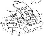
- FIG. 1illustrates a particular coupling used in such environments and offered by Adel Wiggins Group of Los Angeles, Calif., assignee of the present invention.
- the coupling shownis ubiquitous on aircraft fuel systems and is comprised of two semi-circular members that are hinged together at a first location to enable the coupling to pivot open for receiving a conduit or tubing.
- a clamping mechanismcomprising three to four latches are rotated closed to tighten the coupling about the tubing(s).
- the latchesare arranged so that adjacent latches are mounted on opposite ends of the respective opposed ends of the mating members and rotate closed in opposite directions to provide a more secure locking arrangement for the clamping mechanism.
- the clamping mechanismmay not latch properly, preventing the coupling from fully closing. This can lead to an undesirable loss of the coupling function, particularly on high performance applications such as aircraft or other aerospace applications.
- the present inventionis an indicator for the clamping mechanism that provides both visual and tactile confirmation that the latches are locked or unlocked, minimizing the opportunity for a release of the coupling due to a misapplied or insecure clamping mechanism.
- the indicatoris a spring actuated cover having first and second peripheral slots for translational and rotational movement about a pin on the clamping mechanism.
- a pair of rearwardly projecting tabsare positioned so as to arrest rotation of the indicator beyond a designated position, abutting one or more latches or the supporting structure beyond a specific rotation.
- Horizontally projecting armsextend below and are retained by a pin on the clamping mechanism when the latches are fully locked, fixing the indicator in a closed position against the bias of a torsional and compression spring.
- the indicatorcannot be retained in the closed position unless the latches are locked, and the retention of the tabs beneath the pin of the clamping mechanism releases the biasing force of the spring and provides a user with both visual and tactile feedback as to the status of the clamping mechanism of the coupling.
- FIG. 1Ais an elevated perspective view of a prior art coupling for use with the present invention
- FIG. 1Bis another elevated perspective view of the prior art coupling of FIG. 1A ;
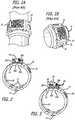
- FIG. 2is an elevated, perspective view of a tubular coupling with the indicator of the present invention mounted thereon in the closed position;
- FIG. 3is an elevated, perspective view of the tubular coupling with the indicator of the present invention mounted thereon in the open position;
- FIG. 4is an enlarged perspective view of the rear of the indicator mounted on the coupling
- FIG. 5is an enlarged perspective view of the front of the indicator mounted on the coupling
- FIGS. 6 and 7are enlarged, elevated perspective views of the indicator in the open configuration.
- FIGS. 8-11are enlarged, perspective views of the indicator transitioning sequentially from the open to the closed position.
- FIGS. 2 and 3illustrate a fluid coupling 20 of the type having first and second semi-circular members 12 hinged together at a first location by a hinge 14 , and a plurality of bonding device 16 mounted on each of the members 12 .
- the coupling 20also includes an inner sleeve 18 enclosed by the two semi-circular members 12 .
- the lightening holes 29are part of the semi-circular members 12 . They serve as a visual check to ensure that sleeve 18 is installed in the coupling 20 and also help to reduce the weight of coupling 20 .
- a clamping mechanism 32as shown in FIGS. 1A and 1B is mounted for adjoining the free ends of the members 12 into an annular coupling 20 .
- the clamping mechanism 32is formed by respective brackets 34 , as shown in FIG. 4 , affixed by rivets to the ends 30 a,b where the brackets 34 each have first and second apertures through which a pin 36 a,b is disposed, one on each bracket.
- each pin 36 a,bjournals two latches 40 .
- the latchescapture pins 36 a,b . That is, when the coupling 20 is formed in a continuous circle, the respective latches 40 on each bracket close and lock onto the opposite pin in alternate fashion to close and lock the coupling onto one or more conduits as shown in FIG. 1 .
- a novel status indicator 50Disposed over the clamping mechanism is a novel status indicator 50 that can provide both visual and tactile feedback on the condition of the latches, specifically whether the latches are fully in the locked position.
- the indicator 50pivots about pin 36 a on the bracket and includes two tabs 76 that tuck below the opposite pin 36 b on the other bracket when the clamping mechanism is closed, establishing that the coupling is properly secured for operation. If the clamping mechanism is not fully closed, the two tabs 76 cannot be tucked under the opposite pin 36 b and the indicator 50 will rotate upward by virtue of a spring biased force, alerting the user to the fact that the coupling is not closed and will not secure the conduit(s) therein.
- FIG. 4illustrates the indicator 50 mounted on the clamping mechanism: the two tabs 76 are under pin 36 b .
- FIG. 5illustrates the indicator 50 at the unlatched position: the two tabs 76 are above the pin 36 b .
- the indicatorcomprises a substantially flat upper surface 52 having a curled front edge 54 and two rearwardly projecting rectangular tabs 56 a,b .
- the rectangular tabs 56 a,bare spaced apart by a gap equal to approximately the width of an individual latch 40 so that the indicator 50 may straddle one of the latches in the gap G, as shown in FIG. 7 , between the tabs 56 a,b .
- the substantially flat upper surface 52 , curled front edge 54 , and rearwardly projecting rectangular tabs 56may be formed from a common sheet of material such as aluminum or plastic, molded or punched to the desired shape.
- First and second downwardly extending sidewalls 66link the upper surface 52 to a headed pin 36 a on bracket 34 a via elongate slots 68 in the sidewalls having a diameter sized to receive the pin 36 a in a sliding relationship, such that the indicator 50 when seated such that the pin 36 a bears against the end of the slots 68 may pivot about the pin 36 a .
- the slots 68are formed such that the indicator may rotate and translate within the slots.
- a torsion and compression spring 58is provided that is wound around the pin 36 a at its periphery and includes a central loop 60 that is held against an underside of the flat upper surface 52 of the indicator 50 and the upper surface of the semi-circular members 12 underneath the two latches 40 that were installed onto the headed pin 36 a .
- the central loop 60is secured to the indicator with tabs 62 formed by cut-outs 64 shaped to grasp the central portion of the torsional and compression spring 58 as the spring biases the indicator with a compression load between the tabs 62 and the headed pin 36 a .
- the torque applied by the torsional and compression spring 58is sufficient to rotate the indicator about the pin 36 a until the tabs 56 a bear against bracket 34 (or tab 56 b bears against the center latch) below the indicator 50 (see FIGS. 6 and 7 ). This causes the indicator 50 to tilt angularly away from the clamping mechanism 32 and clearly visually indicate that the indicator has not been placed in the closed position.
- FIGS. 8-11illustrate the closing sequence of the indicator 50 to visually and tactilely verify that the clamping mechanism is closed.
- the indicator 50can rotate about pin 36 a within slots 68 , and with a thumb or forefinger the curled front edge 54 of the upper surface 52 can be rotated and translated downward against the bias of the torsion and compression spring 58 from the position in FIG. 8 through the position in FIG. 9 (rotation) to the position in FIG. 10 (compression and translation).
- the indicatoris rotated downward, the indicator is stopped by the tabs 76 on the pin 36 b due to the interference between the two.
- a compression loadwill have to be asserted on the edge 54 using a thumb or forefinger to overcome the interference of tabs 76 and pin 36 b as shown in FIG. 9 .
- This translation of the indicator 50 within the slots 68provides clearance so that a pair of arms 76 attached to the bottom of the sidewalls 66 and depend therefrom in a forward direction can pass in front of the pin 36 b on the opposite bracket 34 b .
- Pin 36 bis secured by crimping on both ends. The crimp is located next to the side face of the bracket 34 b . The crimps are small enough to secure the pin from sliding and at the same time they do not interfere with the inner edges of the tabs 76 during the latching of the indicator.
- the upper surface 52is parallel with the upper surfaces of the latches 40 on the clamping mechanism 32 , and the lower surface of the curled front edge 54 may bear against the upper surface of the latches as shown in FIG.
- the indicator 50is slid forward so that the arms 76 reside below the pin 36 b as shown in FIG. 11 and the pin 36 a is at the rearmost portion of the slot 68 .
- the torsional and compression spring 58applies a rotational force on the indicator 50 , but the presents of the pin 36 b and its contact with the arm 76 prevents the rotation of the indicator.
- the clamping mechanismis securely closed, the indicator will maintain the position of FIG. 11 and cannot open, and a user will be able to appreciate from viewing the indicator that the coupling must be securely engaged if the indicator is in the closed position.
- the brackets on opposite ends of the couplingbe in proximity such that the indicator can close. Otherwise, the arms 76 will not pass under the pin 36 b and the spring will rotate the indicator open. Further, the latches if open will not provide a flat surface from which the indicator may approach the pins of the brackets to achieve the closure position. Conversely, the latches cannot open while the indicator is in the closed position. In this manner, the indicator provides both a visual (the observation of the closure position) plus a tactile (the feel of the indicator unable to rotate freely when compressed) that provides feedback to the user that the coupling is secure.
Landscapes
- Engineering & Computer Science (AREA)
- General Engineering & Computer Science (AREA)
- Mechanical Engineering (AREA)
- Quick-Acting Or Multi-Walled Pipe Joints (AREA)
Abstract
Description
Claims (2)
Priority Applications (1)
| Application Number | Priority Date | Filing Date | Title |
|---|---|---|---|
| US15/719,116US11009159B2 (en) | 2017-09-28 | 2017-09-28 | Visual and tactile latch indicator for a fuel system coupling |
Applications Claiming Priority (1)
| Application Number | Priority Date | Filing Date | Title |
|---|---|---|---|
| US15/719,116US11009159B2 (en) | 2017-09-28 | 2017-09-28 | Visual and tactile latch indicator for a fuel system coupling |
Publications (2)
| Publication Number | Publication Date |
|---|---|
| US20190093801A1 US20190093801A1 (en) | 2019-03-28 |
| US11009159B2true US11009159B2 (en) | 2021-05-18 |
Family
ID=65807331
Family Applications (1)
| Application Number | Title | Priority Date | Filing Date |
|---|---|---|---|
| US15/719,116Active2039-07-15US11009159B2 (en) | 2017-09-28 | 2017-09-28 | Visual and tactile latch indicator for a fuel system coupling |
Country Status (1)
| Country | Link |
|---|---|
| US (1) | US11009159B2 (en) |
Families Citing this family (4)
| Publication number | Priority date | Publication date | Assignee | Title |
|---|---|---|---|---|
| CN110440068B (en)* | 2019-09-02 | 2021-02-05 | 淄博爱科工矿机械有限公司 | Adjustable hoop |
| US20210227782A1 (en)* | 2020-01-23 | 2021-07-29 | Kyle Donald Morrison | Swine feeding system and method of cleaning same |
| US11608917B2 (en)* | 2020-03-09 | 2023-03-21 | AdelWiggins Group, a Division of Transdigm Inc. | Non-metallic fluid coupling |
| US20240175526A1 (en)* | 2022-11-28 | 2024-05-30 | Eaton Intelligent Power Limited | Coupling assembly, coupling system and links |
Citations (18)
| Publication number | Priority date | Publication date | Assignee | Title |
|---|---|---|---|---|
| US2133558A (en)* | 1938-03-19 | 1938-10-18 | Lester A Miller | Coupling device |
| US2643138A (en)* | 1949-03-03 | 1953-06-23 | Pacific Pipe Company | Pivoted detent pipe coupling |
| DE1096245B (en)* | 1952-10-11 | 1960-12-29 | Weyer & Zander K G | Closure for two-part protective boxes for electrical devices |
| US4181333A (en)* | 1978-03-31 | 1980-01-01 | Keeler Corporation | Sash lock |
| US4249786A (en)* | 1978-11-03 | 1981-02-10 | Hydraflow Supply, Inc. | Flexible coupling |
| US5129683A (en)* | 1988-09-21 | 1992-07-14 | Gilles Briet | Quick coupling device, in particular for fluid ducts in a motor vehicle |
| US5628531A (en)* | 1995-04-26 | 1997-05-13 | Bundy Corporation | Quick connector with secondary latch |
| US6880859B2 (en)* | 2003-07-31 | 2005-04-19 | Stanley Aviation Corporation | Conduit coupling assembly |
| US6971682B2 (en)* | 2003-04-15 | 2005-12-06 | Adel Wiggins Group, Transdigm, Inc. | Coupling assembly |
| US7226092B2 (en)* | 2002-12-03 | 2007-06-05 | Sugatsune Kogyo Co., Ltd. | Fastening device with lock mechanism |
| US20080315576A1 (en)* | 2006-04-26 | 2008-12-25 | A. Raymond Et Cie | Fluid Line Coupling |
| US20090096209A1 (en)* | 2007-10-10 | 2009-04-16 | Transdigm, Inc., | Flexible, self-bonding coupling assembly |
| US7540364B2 (en)* | 2004-09-01 | 2009-06-02 | Skb Corporation | Trigger latch assembly |
| US8075024B2 (en)* | 2008-06-30 | 2011-12-13 | Eaton Corporation | Coupling assembly |
| DE102014106709B3 (en)* | 2014-05-13 | 2014-12-18 | Norma Germany Gmbh | Coupling element of a quick coupling for media-carrying systems and quick coupling |
| US9261211B2 (en)* | 2013-10-11 | 2016-02-16 | Eaton Corporation | Latching mechanisms for clamshell type couplers |
| US20180135786A1 (en)* | 2015-05-05 | 2018-05-17 | Zodiac Fluid Equipment | Coupling collar and device for coupling pipes comprising such a coupling collar |
| DE102017208643A1 (en)* | 2017-05-22 | 2018-11-22 | Aft Automotive Gmbh | Coupling element for connecting a first fluid-carrying line to a second fluid-carrying line and coupling arrangement |
- 2017
- 2017-09-28USUS15/719,116patent/US11009159B2/enactiveActive
Patent Citations (18)
| Publication number | Priority date | Publication date | Assignee | Title |
|---|---|---|---|---|
| US2133558A (en)* | 1938-03-19 | 1938-10-18 | Lester A Miller | Coupling device |
| US2643138A (en)* | 1949-03-03 | 1953-06-23 | Pacific Pipe Company | Pivoted detent pipe coupling |
| DE1096245B (en)* | 1952-10-11 | 1960-12-29 | Weyer & Zander K G | Closure for two-part protective boxes for electrical devices |
| US4181333A (en)* | 1978-03-31 | 1980-01-01 | Keeler Corporation | Sash lock |
| US4249786A (en)* | 1978-11-03 | 1981-02-10 | Hydraflow Supply, Inc. | Flexible coupling |
| US5129683A (en)* | 1988-09-21 | 1992-07-14 | Gilles Briet | Quick coupling device, in particular for fluid ducts in a motor vehicle |
| US5628531A (en)* | 1995-04-26 | 1997-05-13 | Bundy Corporation | Quick connector with secondary latch |
| US7226092B2 (en)* | 2002-12-03 | 2007-06-05 | Sugatsune Kogyo Co., Ltd. | Fastening device with lock mechanism |
| US6971682B2 (en)* | 2003-04-15 | 2005-12-06 | Adel Wiggins Group, Transdigm, Inc. | Coupling assembly |
| US6880859B2 (en)* | 2003-07-31 | 2005-04-19 | Stanley Aviation Corporation | Conduit coupling assembly |
| US7540364B2 (en)* | 2004-09-01 | 2009-06-02 | Skb Corporation | Trigger latch assembly |
| US20080315576A1 (en)* | 2006-04-26 | 2008-12-25 | A. Raymond Et Cie | Fluid Line Coupling |
| US20090096209A1 (en)* | 2007-10-10 | 2009-04-16 | Transdigm, Inc., | Flexible, self-bonding coupling assembly |
| US8075024B2 (en)* | 2008-06-30 | 2011-12-13 | Eaton Corporation | Coupling assembly |
| US9261211B2 (en)* | 2013-10-11 | 2016-02-16 | Eaton Corporation | Latching mechanisms for clamshell type couplers |
| DE102014106709B3 (en)* | 2014-05-13 | 2014-12-18 | Norma Germany Gmbh | Coupling element of a quick coupling for media-carrying systems and quick coupling |
| US20180135786A1 (en)* | 2015-05-05 | 2018-05-17 | Zodiac Fluid Equipment | Coupling collar and device for coupling pipes comprising such a coupling collar |
| DE102017208643A1 (en)* | 2017-05-22 | 2018-11-22 | Aft Automotive Gmbh | Coupling element for connecting a first fluid-carrying line to a second fluid-carrying line and coupling arrangement |
Non-Patent Citations (1)
| Title |
|---|
| Machine Translation of DE 1096245, 2020, pp. 1-5 (Year: 2020).* |
Also Published As
| Publication number | Publication date |
|---|---|
| US20190093801A1 (en) | 2019-03-28 |
Similar Documents
| Publication | Publication Date | Title |
|---|---|---|
| US11009159B2 (en) | Visual and tactile latch indicator for a fuel system coupling | |
| US7758082B2 (en) | Fluid line connector safety device | |
| US4249786A (en) | Flexible coupling | |
| US5620210A (en) | Fluid conduit coupling | |
| EP2527670B1 (en) | Magnetic carabiner system | |
| US4900070A (en) | Conduit coupling device with redundancy features | |
| CN105387298A (en) | Reusable clamp with latch release arm for connecting conduit sections and associated methods | |
| US8973889B2 (en) | Tube clamp | |
| US6070308A (en) | Double locking snap hook | |
| US6089619A (en) | Locking cam-type coupling | |
| WO2012001894A1 (en) | Fuel tank pipe structure | |
| US6053540A (en) | Fluid conducting coupling | |
| US7354077B1 (en) | Quick connect/disconnect coupler with locking strap | |
| TWM427413U (en) | Safety buckle ring | |
| US20190032829A1 (en) | Double Cam Levers and Safety Lock for Cam Lock Fitting | |
| US20090274509A1 (en) | Ring binder mechanism with sliding hinge plate | |
| US4385423A (en) | Over-center latching coupling | |
| WO2010123434A1 (en) | Band lock for a child carrying device | |
| JP7231167B2 (en) | safety device | |
| US9306360B1 (en) | Torsion eliminating compression device and method | |
| US8702360B1 (en) | Adjustable cargo tie down device | |
| US9717296B2 (en) | Locking clip and anchor assembly for a tether | |
| US11286973B1 (en) | Systems and methods for carabiner gate automatic locking | |
| EP0211943A1 (en) | Quick connect coupling safety clamp system | |
| KR200487714Y1 (en) | Folding apparatus for bicycle |
Legal Events
| Date | Code | Title | Description |
|---|---|---|---|
| FEPP | Fee payment procedure | Free format text:ENTITY STATUS SET TO UNDISCOUNTED (ORIGINAL EVENT CODE: BIG.); ENTITY STATUS OF PATENT OWNER: LARGE ENTITY | |
| AS | Assignment | Owner name:ADELWIGGINS GROUP, CALIFORNIA Free format text:ASSIGNMENT OF ASSIGNORS INTEREST;ASSIGNOR:LEE, BENG POH;REEL/FRAME:043854/0461 Effective date:20171010 | |
| STPP | Information on status: patent application and granting procedure in general | Free format text:DOCKETED NEW CASE - READY FOR EXAMINATION | |
| AS | Assignment | Owner name:ADELWIGGINS GROUP, A DIVISION OF TRANSDIGM INC., C Free format text:ASSIGNMENT OF ASSIGNORS INTEREST;ASSIGNOR:ADELWIGGINS GROUP;REEL/FRAME:045832/0500 Effective date:20180502 Owner name:ADELWIGGINS GROUP, A DIVISION OF TRANSDIGM INC., CALIFORNIA Free format text:ASSIGNMENT OF ASSIGNORS INTEREST;ASSIGNOR:ADELWIGGINS GROUP;REEL/FRAME:045832/0500 Effective date:20180502 | |
| STPP | Information on status: patent application and granting procedure in general | Free format text:NON FINAL ACTION MAILED | |
| STPP | Information on status: patent application and granting procedure in general | Free format text:RESPONSE TO NON-FINAL OFFICE ACTION ENTERED AND FORWARDED TO EXAMINER | |
| STPP | Information on status: patent application and granting procedure in general | Free format text:FINAL REJECTION MAILED | |
| STPP | Information on status: patent application and granting procedure in general | Free format text:NOTICE OF ALLOWANCE MAILED -- APPLICATION RECEIVED IN OFFICE OF PUBLICATIONS | |
| STPP | Information on status: patent application and granting procedure in general | Free format text:PUBLICATIONS -- ISSUE FEE PAYMENT RECEIVED | |
| STPP | Information on status: patent application and granting procedure in general | Free format text:PUBLICATIONS -- ISSUE FEE PAYMENT VERIFIED | |
| STCF | Information on status: patent grant | Free format text:PATENTED CASE | |
| MAFP | Maintenance fee payment | Free format text:PAYMENT OF MAINTENANCE FEE, 4TH YEAR, LARGE ENTITY (ORIGINAL EVENT CODE: M1551); ENTITY STATUS OF PATENT OWNER: LARGE ENTITY Year of fee payment:4 |