US11009156B2 - Composite drill pipe - Google Patents
Composite drill pipeDownload PDFInfo
- Publication number
- US11009156B2 US11009156B2US15/599,369US201715599369AUS11009156B2US 11009156 B2US11009156 B2US 11009156B2US 201715599369 AUS201715599369 AUS 201715599369AUS 11009156 B2US11009156 B2US 11009156B2
- Authority
- US
- United States
- Prior art keywords
- distally
- joint
- pipe
- sleeve
- composite
- Prior art date
- Legal status (The legal status is an assumption and is not a legal conclusion. Google has not performed a legal analysis and makes no representation as to the accuracy of the status listed.)
- Expired - Lifetime, expires
Links
Images


Classifications
- F—MECHANICAL ENGINEERING; LIGHTING; HEATING; WEAPONS; BLASTING
- F16—ENGINEERING ELEMENTS AND UNITS; GENERAL MEASURES FOR PRODUCING AND MAINTAINING EFFECTIVE FUNCTIONING OF MACHINES OR INSTALLATIONS; THERMAL INSULATION IN GENERAL
- F16L—PIPES; JOINTS OR FITTINGS FOR PIPES; SUPPORTS FOR PIPES, CABLES OR PROTECTIVE TUBING; MEANS FOR THERMAL INSULATION IN GENERAL
- F16L15/00—Screw-threaded joints; Forms of screw-threads for such joints
- F16L15/08—Screw-threaded joints; Forms of screw-threads for such joints with supplementary elements
- E—FIXED CONSTRUCTIONS
- E21—EARTH OR ROCK DRILLING; MINING
- E21B—EARTH OR ROCK DRILLING; OBTAINING OIL, GAS, WATER, SOLUBLE OR MELTABLE MATERIALS OR A SLURRY OF MINERALS FROM WELLS
- E21B17/00—Drilling rods or pipes; Flexible drill strings; Kellies; Drill collars; Sucker rods; Cables; Casings; Tubings
- E21B17/003—Drilling rods or pipes; Flexible drill strings; Kellies; Drill collars; Sucker rods; Cables; Casings; Tubings with electrically conducting or insulating means
- E—FIXED CONSTRUCTIONS
- E21—EARTH OR ROCK DRILLING; MINING
- E21B—EARTH OR ROCK DRILLING; OBTAINING OIL, GAS, WATER, SOLUBLE OR MELTABLE MATERIALS OR A SLURRY OF MINERALS FROM WELLS
- E21B17/00—Drilling rods or pipes; Flexible drill strings; Kellies; Drill collars; Sucker rods; Cables; Casings; Tubings
- E21B17/02—Couplings; joints
- E21B17/028—Electrical or electro-magnetic connections
- E21B17/0285—Electrical or electro-magnetic connections characterised by electrically insulating elements
- E—FIXED CONSTRUCTIONS
- E21—EARTH OR ROCK DRILLING; MINING
- E21B—EARTH OR ROCK DRILLING; OBTAINING OIL, GAS, WATER, SOLUBLE OR MELTABLE MATERIALS OR A SLURRY OF MINERALS FROM WELLS
- E21B17/00—Drilling rods or pipes; Flexible drill strings; Kellies; Drill collars; Sucker rods; Cables; Casings; Tubings
- E21B17/20—Flexible or articulated drilling pipes, e.g. flexible or articulated rods, pipes or cables
- E21B17/206—Flexible or articulated drilling pipes, e.g. flexible or articulated rods, pipes or cables with conductors, e.g. electrical, optical
- F—MECHANICAL ENGINEERING; LIGHTING; HEATING; WEAPONS; BLASTING
- F16—ENGINEERING ELEMENTS AND UNITS; GENERAL MEASURES FOR PRODUCING AND MAINTAINING EFFECTIVE FUNCTIONING OF MACHINES OR INSTALLATIONS; THERMAL INSULATION IN GENERAL
- F16L—PIPES; JOINTS OR FITTINGS FOR PIPES; SUPPORTS FOR PIPES, CABLES OR PROTECTIVE TUBING; MEANS FOR THERMAL INSULATION IN GENERAL
- F16L13/00—Non-disconnectable pipe joints, e.g. soldered, adhesive, or caulked joints
- F16L13/10—Adhesive or cemented joints
- F16L13/103—Adhesive joints
- F—MECHANICAL ENGINEERING; LIGHTING; HEATING; WEAPONS; BLASTING
- F16—ENGINEERING ELEMENTS AND UNITS; GENERAL MEASURES FOR PRODUCING AND MAINTAINING EFFECTIVE FUNCTIONING OF MACHINES OR INSTALLATIONS; THERMAL INSULATION IN GENERAL
- F16L—PIPES; JOINTS OR FITTINGS FOR PIPES; SUPPORTS FOR PIPES, CABLES OR PROTECTIVE TUBING; MEANS FOR THERMAL INSULATION IN GENERAL
- F16L25/00—Construction or details of pipe joints not provided for in, or of interest apart from, groups F16L13/00 - F16L23/00
- F16L25/0018—Abutment joints
- E—FIXED CONSTRUCTIONS
- E21—EARTH OR ROCK DRILLING; MINING
- E21B—EARTH OR ROCK DRILLING; OBTAINING OIL, GAS, WATER, SOLUBLE OR MELTABLE MATERIALS OR A SLURRY OF MINERALS FROM WELLS
- E21B17/00—Drilling rods or pipes; Flexible drill strings; Kellies; Drill collars; Sucker rods; Cables; Casings; Tubings
- E21B17/02—Couplings; joints
- E—FIXED CONSTRUCTIONS
- E21—EARTH OR ROCK DRILLING; MINING
- E21B—EARTH OR ROCK DRILLING; OBTAINING OIL, GAS, WATER, SOLUBLE OR MELTABLE MATERIALS OR A SLURRY OF MINERALS FROM WELLS
- E21B17/00—Drilling rods or pipes; Flexible drill strings; Kellies; Drill collars; Sucker rods; Cables; Casings; Tubings
- E21B17/20—Flexible or articulated drilling pipes, e.g. flexible or articulated rods, pipes or cables
- F—MECHANICAL ENGINEERING; LIGHTING; HEATING; WEAPONS; BLASTING
- F16—ENGINEERING ELEMENTS AND UNITS; GENERAL MEASURES FOR PRODUCING AND MAINTAINING EFFECTIVE FUNCTIONING OF MACHINES OR INSTALLATIONS; THERMAL INSULATION IN GENERAL
- F16L—PIPES; JOINTS OR FITTINGS FOR PIPES; SUPPORTS FOR PIPES, CABLES OR PROTECTIVE TUBING; MEANS FOR THERMAL INSULATION IN GENERAL
- F16L31/00—Arrangements for connecting hoses to one another or to flexible sleeves
- Y—GENERAL TAGGING OF NEW TECHNOLOGICAL DEVELOPMENTS; GENERAL TAGGING OF CROSS-SECTIONAL TECHNOLOGIES SPANNING OVER SEVERAL SECTIONS OF THE IPC; TECHNICAL SUBJECTS COVERED BY FORMER USPC CROSS-REFERENCE ART COLLECTIONS [XRACs] AND DIGESTS
- Y10—TECHNICAL SUBJECTS COVERED BY FORMER USPC
- Y10T—TECHNICAL SUBJECTS COVERED BY FORMER US CLASSIFICATION
- Y10T29/00—Metal working
- Y10T29/49—Method of mechanical manufacture
- Y10T29/49826—Assembling or joining
Definitions
- the present inventionrelates to composite torque tubes and the method for forming the same.
- Tewappears to disclose a single metal-composite interface held together by radial pins and an adhesive bond which may suffer from disparate torsional forces.
- Tewappears to propose a cylindrical outer protective sheath drawn over the pipe and lacking a tapered surface interface and suffers the shortcoming that, the coupling itself fails to provide a high strength joint capable of carrying the high torsional force necessary to withstand the loads of both extended reach applications and short radius.
- the present inventionis directed to a composite to metal joint for connecting composite torque pipe to a mechanical end fitting.
- the deviceis a metal inner sleeve configured with a barrel and sleeve projecting from an annular flange to define on its exterior a distally narrowing conical shell surface.
- One end of an exterior sleeveis telescoped over the barrel and is formed with a distally projecting outer shell formed with an interior smooth conical inner shell surface concentric with the inner shell itself and cooperating therewith to form an annulus distally expanding in radial thickness
- a composite torque pipeis formed with an extremity formed with a concentrically tapered connector ring configured to compliment the shape of the annulus.
- the ringis inserted in the annulus and a bonding material is applied to the interface between the sleeve surfaces and the connector ring and allowed to cure.
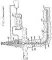
- FIG. 1is a perspective illustration, separated by parts, of a conventional drill pipe string extended into a well bore;
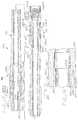
- FIG. 2is an exploded perspective illustration, partially in section, of the metal to composite end fitting assembly embodying the pipe assembly;
- FIG. 3is a further perspective illustration of the pipe assembly incorporating the parts illustrated in FIG. 2 ;
- FIG. 4is a sectional view, of a coupled pipe joint illustrating the signal connection between pipe parts shown in FIG. 2 ;
- FIG. 5is an enlarged end view taken along the line 5 - 5 shown in FIG. 4 .
- FIG. 6is an enlarged end view taken along the line 6 - 6 shown in FIG. 4 .
- FIG. 7is a side view, enlarged of the circle shown in FIG. 4 .
- FIG. 8is a side view, enlarged of the circle shown in FIG. 4 .
- FIG. 9is a perspective illustration, in partial section, of the tooling arrangement useful in combining the inventive assembly into an integral fixture
- FIG. 10is a diagrammatic view, in perspective, illustrating the inventive implementation of a forming facility useful in forming the composite pipe segment on a rotary mount incorporating portions of the end fitting assembly;
- FIG. 11is an enlarged cross sectional end view taken along the line 11 - 11 of FIG. 10 ;
- FIG. 12is a sequence diagram of an end fitting assembly sequence in accordance with the present invention.
- FIG. 13is a perspective exploded illustration, of a second embodiment of the metal to composite end fitting of the present invention and showing an electrical contact mechanism bridging electrical conduction across a threaded pipe joint;
- FIG. 14is an enlarged sectional detail view of the contact mechanism shown generally in FIG. 13 before the full threaded engagement of a pipe joint;
- FIG. 15is an enlarged sectional detail view of the contact mechanism shown generally in FIG. 13 after the full threaded engagement of a pipe joint;
- FIG. 16is a side cross sectional view of the threaded joint interface and contact mechanism shown generally in FIG. 13 ;
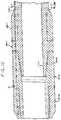
- FIG. 17is a broken longitudinal sectional view of a third embodiment of the pipe assembly shown in FIG. 3 ;
- FIG. 18is a detailed view in enlarged scale taken from the circle 18 shown in FIG. 17 .
- This same complexity of the rigalso determines the manipulation convenience of each of the pipe segments PS, again resulting in its own logistic and mechanical constraints resolved by the size of the rig (or off-shore platform) that can be effectively implemented at the well site, thereby limiting the length of each segment PS and multiplying the number of required joints JT that need to be made to extend the string to the desired depth.
- the combined weight of the stringincluding all the down hole joints and any wear knots or pipe protectors 90 shielding the pipe from wall contact, along with the friction load resulting from this wall contact, are thus resolved at the last surface joint which sets the design limit. It is within this limit that the rig operator tries to discover oil by periodic insertion of instruments down the bore, or simply by inspecting the drilling debris brought to the surface.
- one aspect of the inventive pipe assemblycomprises a tubular composite pipe segment 11 , formed by winding up reinforcing fiber, such as carbon fiber, preferably wound in stress determined orientation patterns between plies of interleaved wrapping, all bonded together by resinous filler to form a cylindrical structure of a generally uniform wall thickness over most of its length.
- reinforcing fibersuch as carbon fiber
- Pipe segment 11may be formed with a generally uniform taper along a selected portion of each end 12 - 1 and 12 - 2 reducing in wall thickness.
- Each endmay be defined by interior and exterior wall surfaces 12 i and 12 e respectively, that are configured for receipt within conforming annular cavities formed by male and female couplers comprising a set of nested metallic end fittings 20 - 1 and 20 - 2 and metallic sleeves 30 - 1 and 30 - 2 .
- Those skilled in the artwill appreciate that the surfaces of the pipe segment and adjoining structures for that matter, may use other surface configurations, yet, in one embodiment, tapered and frustoconical surfaces are used permitting a diffusion of torsional loads across the surfaces of connected pieces.
- the metallic end fittings 20 - 1 and 20 - 2include a flange 29 with shoulders 29 - 1 and 29 - 2 and skirt 23 including an exterior surface 22 e tapering in reducing cross section away from the flange.
- the metallic sleeves 30 - 1 and 30 - 2include respective telescoping flanges 39 and skirts 33 formed with interior surfaces 32 i tapering and expanding cross section away from the flange to, when assembled with the respective fittings 20 - 1 and 20 - 2 cooperate in defining an annulus distally expanding in thickness ( FIG. 9 ).
- the annular cavities formed by the nested piecesare formed by axially aligning the tapered exterior surface 22 e of skirt 23 adjacent an oppositely tapered surface 32 i on the skirt 33 interior.
- the surfaces 22 e and 32 iare each closely matched to respective dimensions and tapered surfaces 12 e and 12 i where insertion of the surfaces 12 e and 12 i into the annular cavity forms an aligned pipe segment end interface.
- this self-aligning constructioncreates a bonding interface that can be effected by any high temperature epoxy resin and will further appreciate that the close fit of this bond is further enhanced by close dimensional matching between the coaxially nested end fitting and sleeve pieces so that the sleeve forms a peripheral support for the tapered end of the pipe segment as it is slid into position within the end fitting.
- each of the skirts 23 and 33may include a radially matched set of lateral openings 24 and 34 dimensioned for press fit or interference receipt of corresponding optionally used pins 45 that also pass through corresponding circular openings 15 formed in the tapered ends 12 - 1 and 12 - 2 once the ends are fully received, bonded and indexed within their receiving cavities.
- This same indexed alignmentmay orient the exposed ends 18 of conductor leads 17 that are woven into the filament matrix of the pipe segment 11 into alignment with longitudinal drillings 37 formed in skirts 33 to effect an electrical connection across the pipe joint herein described.
- each of the piecesis formed as a closely dimensioned telescoping cylindrical segments 26 and 36 which are each provided with corresponding exterior flanges 29 and 39 aligned next to each other when the skirts are properly positioned.
- the same drillings 37extend through the flange 39 to convey the lead ends 18 there-through.
- end fitting 20 - 1includes a threaded boss 51 - 1 extending beyond the exterior shoulder 29 - 1 of the flange 29 that is conformed for threaded receipt in a threaded cavity 51 - 2 formed in the other exterior shoulder 29 - 2 of the other flange 29 on the end fitting piece 20 - 2 .
- Each of the flanges 29includes drilling continuations shown as drillings 27 - 1 and 27 - 2 ( FIG.
- drilling 27 - 1conveying the conductor end 18 into a circular recess 53 - 1 formed in the flange shoulder surface 29 - 1 where the lead is connected to an insulated ring 54 - 1 conformed for receipt within the interior of recess 53 - 1 .
- the overall length of the pipe assembly 10measures approximately 359 inches.
- the composite pipe 11measures 338.00 inches long between respective outer sleeve proximal ends 30 - 1 and 30 - 2 and includes an inner diameter of 1.625 inches and an outer diameter of 2.510 inches intermediate the end assemblies.
- the diametersexpand outwardly therefrom toward the assembly fittings where the pipe inner surface 12 i and exterior surface 12 e respectively are formed with radial dimensions matching their confrontment with end fitting exterior surface 22 e and sleeve inner surface 32 i respectively.
- the overall pipe string diameterexpands from the composite pipe 11 outer diameter of 2.510 inches to a metallic fitting end diameter of 3.405 inches.
- the length of the “pin” end assemblymeasures approximately 10.00 inches from the distal end of male boss 51 - 1 to the outer sleeve 30 - 1 proximal end.
- the “box” end assemblymeasures approximately 1.00 inch longer between respective like features of female boss 51 - 2 and sleeve end 30 - 2 to accommodate the male boss 51 - 1 .
- the length of the drill string of the presently described embodimentis approximately 86% composite material length compared to approximately 14% metallic material length.
- the metalis primarily reserved for the end fittings 20 and sleeves 30 that support the joint interface to the composite pipe segment 11 and provide strengthened joint coupling between adjacent pipe assemblies where tensile loads can do significant harm.
- composite pipe 11 wallsmay also be conveniently adjusted to thicker or thinner thicknesses depending on the depth of drilling by forming the pipe segments with more or less composite layers.
- the drill stringis conducive to carrying torsional loads by both the internal fitting to composite wall interface and by the metallic outer sleeve.
- force loadsare distributed along the walls of the drill pipe assembly and are diffused over pipe walls expanding from the intermediate portion toward the joint assembly interfaces and ends.
- these loadsencounter the dual tapered surface interface between the metallic end fittings 20 and metallic sleeves 30 confronting the composite pipe disposed intermediately there-between distributing the loads across two surfaces interfaces.
- the tapered surfacescreate a larger area of load confrontment thereby diffusing the load effects over a greater surface area.
- end fitting 20 - 2includes a drilling 27 - 2 indexed with drilling 37 in the sleeve 30 - 2 to convey the other conductor end 18 into a manifold 56 ( FIG. 8 ) formed in flange 29 and terminating in one or more openings 57 through shoulder surface 29 - 2 opposing the recess 53 - 1 when the ends are threadably mated. Opening 57 , may in turn, be provided with a spring biased piston 58 carrying a bayonet point 59 .
- FIG. 5a sectional end view of the “pin” end is illustrated showing the insulated contact ring 54 - 1 circumscribed within the circular recess within the flange 29 - 1 .
- FIG. 5The assembly of circular features in FIG. 5 are shown in relation to the features of FIG. 6 where the spring-biased piston and bayonet point on the “box” end in manifold 56 are in circumferential alignment to the ring.
- the fitting end pieces 20 - 1 and 20 - 2may be combined with a forming mandrel effected by an inner core layer 111 ( FIG. 10 ), to form the turning core for the subsequent winding of fiber plies 92 and the remaining interleaved layers 93 forming the composite pipe 11 , in step 201 .
- the winding pitch, fiber density and the selection of any sealing wrapsmay also be determined by the particular parameters of the well and the mandrel structure may be further stiffened and assisted by internal pressurization while the fiber wind-up tension is controlled.
- conductive leads 17may be concurrently also imbedded into the wrap, again in accordance with the type and nature of the signals and/or power that may be conveyed thereon.
- a bonding agentsuch as a high temperature epoxy resin is then applied to the pipe ends tapered rings defining the pipe ends 12 - 1 and 12 - 2 and the ends are then re-positioned into the interiors of sleeve pieces 30 - 1 and 30 - 2 with the end fitting pieces 20 - 1 and 20 - 2 then pressed into their common interiors, shown as the self-centralizing step 203 .
- the exposed conductor ends 18are conveyed into their appropriate drillings to be thereafter connected either to the bayonet contact 59 or the contact ring 54 - 1 .
- step 204the foregoing assembly is then brought into a spray cooled welding fixture illustrated in FIG.
- a weld 91is applied by a welding device 151 to join the exterior flanges of the nested pieces 20 - 1 and 30 - 1 to each other (and by the same example also the nested pieces 20 - 2 and 30 - 2 ) while water spray heads 152 and 153 cool the adjacent structure.
- the sleeve and end pieces, with the ends 12 - 1 and 12 - 2 captured there-between,are then drilled, in step 205 , with perforations 34 which thereafter receive press fit pins 45 .
- drill pipe stringmay be improved upon to include enhanced configurations for effecting an electrical connection along the pipe string and modifications to the composite-metal interface providing a durable yet flexible structure conducive to short radius drilling.
- a second preferred embodimentemploys the interior and exterior distantly converging tapered surfaces at the opposite extremities of the composite segments 11 and showing an alternative contact implementation is obtained by embedding coaxial contact rings in each of the opposing shoulder surfaces 29 - 1 and 29 - 2 surrounding both the ‘pin’ end and the ‘box’ end of the joint assembly.
- one or the other or both of the tapersmay be in the form of continuous smooth surfaces as shown in FIGS. 2 and 16 or in some instances in the form of stepped surfaces cooperating to progressively narrow the thickness of the segment wall in the distal direction.
- seal 255 - 1is generally shaped as a U sectioned structure defined by concentric inner and outer annular walls 256 i and 256 o extending from a bottom wall 257 .
- a conforming contact ring 261 chamfered along its upper edges by a peripheral chamfer 261 eis then captured by elastic stretching within the annular cavity 256 formed between the inner and outer sealing walls 256 i and 256 o of the seal 255 - 1 with the outer wall stretching just over the chamfer to retain the ring in position.
- a similarly dimensioned contact ring 262is then received in the annular cavity 258 formed between the inner and outer walls 258 i and 258 o of the ‘box’ end seal 255 - 2 , with the groove depth (or wall height) of walls 258 i and 258 o being substantially greater than the thickness of the ring 261 and 262 and the depth of the receiving recess 53 - 2 .
- seal 255 - 1is somewhat less than its receiving recess 53 - 1 .
- both the contact rings 261 and 262are inserted within their respective seals so that each contact surface projects just slightly above the corresponding surface 29 - 1 and 29 - 2 , a projection determined by the dimensions of the annular recesses or grooves 53 - 1 and 53 - 2 and the dimensions of each seal.
- walls 258 i and 258 oeach project beyond the corresponding surface of ring 262 before the threaded engagement of the joint, as illustrated in FIG. 14 .
- both the opposing seals and the rings seated thereinare fixed in rotation in each corresponding recess 53 - 1 and 53 - 2 by way of spaced axial pins 263 and 264 that project from the buried edges of each of the rings 261 and 262 into conforming pockets 259 in each of the seal bottoms which are then inserted into conforming cavities 269 formed in the abutment surface bottoms of each of the recesses 53 - 1 and 53 - 2 ( FIG. 13 ).
- the projecting seal edges and the rings thereintherefore slide in rotation relative each other as the pipe joint is made. As illustrated in FIG.
- the excess volume of the elastomeric matter forming each of the seal walls 258 i and 258 ofills the volume of the concentric annular open-ended grooves defined by the respective edge chamfers 261 e which also assist in the spreading of the seat edges to facilitate a direct contact between the rings as illustrated before the mating in FIG. 14 .
- the edge chamfers in ring 261allow for the elastomeric material flow of the seal material as the joint is threaded together, ensuring a completely surrounding sealing closure as the exposed edges of the rings are pressed against each other while the smaller contact dimension formed between the edge chamfers 261 e assures a better ring contact while also accommodating a somewhat less precise axial registration between the pipe segments.
- This same material flowmay be utilized to both seal and capture the exterior insulation 275 e around a conductor 275 extending through corresponding drillings 271 - 1 and 271 - 2 through corresponding shoulders 38 - 1 and 38 - 2 and extending into one of the cavities 269 in the bottoms of recesses 53 - 1 and 53 - 2 to pass the respective lead ends 275 through the seal material and thereafter into perforations 261 p and 262 p in the corresponding rings 261 and 262 .
- a return conductor 285 connected directly between the pipe segment endscan then be utilized to provide the return or common ground.
- the load carrying capacities of the drill string sectionscan be adjusted accordingly. In this manner, a rugged and reliable contact is effected, thus accommodating both the power and the signal needs in deep well drilling.
- threaded assembliesmay not result in the same two polar points aligning functionally. It may occur that a point on a threaded end does not meet a corresponding point on a receiving end more than once because the boss end may begin at a different point for threading or the degree of torque applied at the end of the threading shifts the points.
- Those skilled in the artwill appreciate that by utilizing contact rings at the end fittings of a threaded pipe assembly, an effective and efficient means for conduction of a signal is maintained even where the conductors are not in direct contact or alignment to one another.
- the contact rings 262 and 261will be in conductive engagement regardless of where the conductor 275 is situated on one end piece after threading relative to where the next conductor 275 is on an adjacent segment.
- the contact ringswill be engaged and the conductors are in conductive proximity to the axial pins 263 of their respective contact ring and insulated from electrical diffusion from one another and the surrounding conductive elements, signal can be successfully transmitted from one conductor through the contact ring conjunction to the next conductor.
- annular seals 255to incorporate the contact rings 261 and 262 , an efficient means of maintaining the conductive integrity is preserved.
- the annular sealassists in protecting the contact ring from the conductive properties and stress imposed by the metal walls of the pipe end fittings.
- signal lossmay be prevented from escaping to the pipe exterior.
- each of the conductorsmay be variously effected either as an electrical power lead, a signal lead or even a fiber optic filament.
- known techniques of signal superposition, frequency and/or pulse modulation or other signaling formatscan then be effected by these leads to bring out down hole information directly to the rig operator as the drilling is taking place which can then be used to modify, in known techniques, the drilling direction and the cutting rate, commonly referred to as LWD or ‘logging while drilling’ and MWD or ‘measuring while drilling.’
- LWDlogging while drilling
- MWDmillimetering while drilling
- the nested pieces and their respective tapered surfacesmay be modified to withstand varying external loads on the pipe joints accommodating flexing during drilling while maintaining a metal-composite interface conducive for carrying a torsional load capacity.
- the drill string configuration 300 in FIGS. 17 and 18is similar to the drill string embodiment shown in FIGS. 2-4 except that the longitudinal length of the inner annular sleeves 323 of the metal end fittings 320 - 1 and 323 are concentric with and project approximately 1 inch beyond the end of the respective outer sleeves 330 - 2 facilitating flexure at the metal-composite junction.
- ends 320 and 330include the inner and outer annular shells 320 - 1 and 320 - 2 , respectively, formed with the respective concentric annular sleeves 323 and 330 - 2 defining respective concentric, annular, confronting, tapered surfaces 332 i and 312 e expanding distally away from one another to form a conical annular nesting cavity for bonded receipt of tapered surfaces 312 i and 312 e of respective pipe segment bonding rings 312 - 1 and 312 - 2 .
- the end fitting 320 - 1is configured with an annular exterior flange 329 - 1 formed with a first distally facing annular stop shoulder 329 - 5 and then projects distally to form an annular radially outwardly projecting flange defining a barrel 329 - 2 and is then stepped down further in diameter to form a second distally facing annular abutment shoulder 329 - 3 spaced from the shoulder 329 - 5 and then projects distally to form the shell 323 , terminating in a distal extremity 328 - 2 .
- the composite pipe segment 311can be constructed to include less carbon material providing more flexibility in the composite segment length.
- the pipe assembly 300is conducive for providing quick turns while maintaining durable integrity during advancement of drilling.
- the outer sleeve 330 - 2is configured with a cylindrical outer surface and is formed proximally with an interior cylindrical, stepped down in diameter to form a cylindrically radially inwardly projecting flange defining a collar 330 - 3 to fit over the barrel 329 - 2 and is stepped up in diameter to form a distally facing abutment shoulder 329 - 4 aligned with the shoulder 329 - 3 to form a combined annular shoulder against which the blunt end of the respective pipe segment rings 312 - 1 and 312 - 2 are abutted.
- the inner sleeveterminates in an extremity projecting distally beyond the distal extremity 338 - 1 of the outer sleeve.
- a weld nutis provided to weld the proximal end of the outer sleeve to the first annular shoulder.
- the fitting 320is configured at its proximal end with a boss 320 - 1 formed with a threaded nipple 320 - 1 .
- the fitting 320 - 2is formed with an internally threaded box 351 - 2 .
- a bond 338 - 2is received in the interface between the outside surface of the pipe 311 and the inner surface 312 e and a second bond at the interface between the exterior surface of the pipe and the interior sleeve surface 332 i.
- the composite walls and offset metallic end portionsprovide a flexure point at the metal-composite interface facilitating directional change during short radius turns.
- the composite pipe wallsare relatively more flexible than the metal end fittings.
- the external metallic sleeve endprovides a flex point for the internal metal end fitting and composite wall to bend from while simultaneously supporting the metal-composite joint interface to partially carry torsional loads.
- the drilling experienceis further enhanced by incorporating the conductor 275 to the pipe assembly 300 without detracting from the efficiency of or compromising the integrity of the assembly structure.
- measuring signals sent along the string via the conductor 275can provide feedback for adjusting rotational speed as well as update the composition of surrounding geological attributes relative to oil proximity.
- the flexibility of the conductorcooperates with the advancement of the pipe assembly 300 , particularly in short radius applications where the conductor can flex right along with the pipe segment during tight turns.
Landscapes
- Engineering & Computer Science (AREA)
- Life Sciences & Earth Sciences (AREA)
- Geology (AREA)
- Mining & Mineral Resources (AREA)
- Mechanical Engineering (AREA)
- General Engineering & Computer Science (AREA)
- Physics & Mathematics (AREA)
- Environmental & Geological Engineering (AREA)
- Fluid Mechanics (AREA)
- General Life Sciences & Earth Sciences (AREA)
- Geochemistry & Mineralogy (AREA)
- Earth Drilling (AREA)
Abstract
Description
Claims (7)
Priority Applications (1)
| Application Number | Priority Date | Filing Date | Title |
|---|---|---|---|
| US15/599,369US11009156B2 (en) | 2004-09-28 | 2017-05-18 | Composite drill pipe |
Applications Claiming Priority (6)
| Application Number | Priority Date | Filing Date | Title |
|---|---|---|---|
| US10/952,135US7458617B2 (en) | 2004-09-28 | 2004-09-28 | Composite drill pipe |
| US12/323,067US20090101328A1 (en) | 2004-09-28 | 2008-11-25 | Composite drill pipe and method of forming same |
| US13/342,952US8287005B2 (en) | 2004-09-28 | 2012-01-03 | Composite drill pipe and method for forming same |
| US13/551,446US8696034B2 (en) | 2004-09-28 | 2012-07-17 | Composite drill pipe and method for forming same |
| US14/251,831US9689514B2 (en) | 2004-09-28 | 2014-04-14 | Composite pipe to metal joint |
| US15/599,369US11009156B2 (en) | 2004-09-28 | 2017-05-18 | Composite drill pipe |
Related Parent Applications (1)
| Application Number | Title | Priority Date | Filing Date |
|---|---|---|---|
| US14/251,831ContinuationUS9689514B2 (en) | 2004-09-28 | 2014-04-14 | Composite pipe to metal joint |
Publications (2)
| Publication Number | Publication Date |
|---|---|
| US20170343138A1 US20170343138A1 (en) | 2017-11-30 |
| US11009156B2true US11009156B2 (en) | 2021-05-18 |
Family
ID=40562276
Family Applications (10)
| Application Number | Title | Priority Date | Filing Date |
|---|---|---|---|
| US12/323,067AbandonedUS20090101328A1 (en) | 2004-09-28 | 2008-11-25 | Composite drill pipe and method of forming same |
| US13/342,952Expired - Fee RelatedUS8287005B2 (en) | 2004-09-28 | 2012-01-03 | Composite drill pipe and method for forming same |
| US13/551,446Expired - LifetimeUS8696034B2 (en) | 2004-09-28 | 2012-07-17 | Composite drill pipe and method for forming same |
| US13/944,723Active2027-11-20US9810353B2 (en) | 2004-09-28 | 2013-07-17 | Method of making a composite tube to metal joint |
| US14/251,831Expired - LifetimeUS9689514B2 (en) | 2004-09-28 | 2014-04-14 | Composite pipe to metal joint |
| US14/838,033Active2026-12-13US11143338B2 (en) | 2004-09-28 | 2015-08-27 | Composite to metal end fitting joint |
| US15/599,369Expired - LifetimeUS11009156B2 (en) | 2004-09-28 | 2017-05-18 | Composite drill pipe |
| US15/599,359Expired - LifetimeUS10378684B2 (en) | 2004-09-28 | 2017-05-18 | Composite tube to metal joint apparatus |
| US15/805,019Expired - LifetimeUS10612703B2 (en) | 2004-09-28 | 2017-11-06 | Composite drill pipe and method for forming same |
| US15/954,241AbandonedUS20180231157A1 (en) | 2004-09-28 | 2018-04-16 | Composite to metal joint and method for forming same |
Family Applications Before (6)
| Application Number | Title | Priority Date | Filing Date |
|---|---|---|---|
| US12/323,067AbandonedUS20090101328A1 (en) | 2004-09-28 | 2008-11-25 | Composite drill pipe and method of forming same |
| US13/342,952Expired - Fee RelatedUS8287005B2 (en) | 2004-09-28 | 2012-01-03 | Composite drill pipe and method for forming same |
| US13/551,446Expired - LifetimeUS8696034B2 (en) | 2004-09-28 | 2012-07-17 | Composite drill pipe and method for forming same |
| US13/944,723Active2027-11-20US9810353B2 (en) | 2004-09-28 | 2013-07-17 | Method of making a composite tube to metal joint |
| US14/251,831Expired - LifetimeUS9689514B2 (en) | 2004-09-28 | 2014-04-14 | Composite pipe to metal joint |
| US14/838,033Active2026-12-13US11143338B2 (en) | 2004-09-28 | 2015-08-27 | Composite to metal end fitting joint |
Family Applications After (3)
| Application Number | Title | Priority Date | Filing Date |
|---|---|---|---|
| US15/599,359Expired - LifetimeUS10378684B2 (en) | 2004-09-28 | 2017-05-18 | Composite tube to metal joint apparatus |
| US15/805,019Expired - LifetimeUS10612703B2 (en) | 2004-09-28 | 2017-11-06 | Composite drill pipe and method for forming same |
| US15/954,241AbandonedUS20180231157A1 (en) | 2004-09-28 | 2018-04-16 | Composite to metal joint and method for forming same |
Country Status (1)
| Country | Link |
|---|---|
| US (10) | US20090101328A1 (en) |
Families Citing this family (47)
| Publication number | Priority date | Publication date | Assignee | Title |
|---|---|---|---|---|
| US8414724B2 (en)* | 2006-12-02 | 2013-04-09 | The Boeing Company | Composite tube having cobonded end fittings and method of making same |
| US20120067649A1 (en)* | 2009-06-08 | 2012-03-22 | National Oilwell Varco, L.P. | Slip free drill pipe |
| WO2011101616A1 (en) | 2010-02-16 | 2011-08-25 | Ball Burnishing Machine Tools Ltd | Method of forming a coupling |
| GB2479552B (en)* | 2010-04-14 | 2015-07-08 | Aker Subsea Ltd | Subsea wellhead providing controlled access to a casing annulus |
| CN101975057A (en)* | 2010-10-28 | 2011-02-16 | 华东理工大学 | Real-time control drilling and production system for deep and ultra-deep wells |
| US9370898B2 (en) | 2010-11-11 | 2016-06-21 | Joinlock Pty Ltd. | Connecting method |
| FR2972215B1 (en)* | 2011-03-01 | 2013-03-22 | Vam Drilling France | DRILLING COMPONENT COMPRISING A MOBILE COUPLER AND A PRESSURE CHAMBER |
| EP2607229B1 (en)* | 2011-12-22 | 2016-05-11 | Airbus Operations, S.L. | Composite rod and manufacturing method |
| US9458708B2 (en)* | 2012-08-07 | 2016-10-04 | Harris Corporation | RF coaxial transmission line for a wellbore including dual-wall outer conductor and related methods |
| US9366094B2 (en)* | 2012-11-30 | 2016-06-14 | Intelliserv, Llc | Pipe joint having coupled adapter |
| USD726289S1 (en)* | 2013-01-28 | 2015-04-07 | Vam Drilling Usa, Inc. | Shale drill pipe |
| US20140253341A1 (en)* | 2013-03-11 | 2014-09-11 | Abrado, Inc. | Method and apparatus for communication of wellbore data, including visual images |
| US10221632B2 (en)* | 2013-03-14 | 2019-03-05 | Ge Energy Oilfield Technology, Inc | Composite isolation joint for gap sub or internal gap |
| EP2989282B1 (en)* | 2013-04-22 | 2017-03-15 | Voith Patent GmbH | Metal pipe having a connector |
| CN104251122B (en)* | 2013-06-28 | 2016-09-07 | 中国石油天然气集团公司 | No-dig technique horizontal directional drill electric drill bar |
| NO20230407A1 (en)* | 2013-07-09 | 2015-11-13 | Halliburton Energy Services Inc | An electrical connector assembly and method of transmitting power or a signal in a wellbore |
| CN103343668A (en)* | 2013-07-22 | 2013-10-09 | 中国石油大学(华东) | Wired cable transmission drilling rod connector |
| CN104420837B (en)* | 2013-09-02 | 2016-08-10 | 深圳市百勤石油技术有限公司 | A kind of method preventing oil pipe from causing footpath to be contracted because torque wrench moment is excessive |
| USD863483S1 (en) | 2014-02-05 | 2019-10-15 | Alignment Pro, Llc | Golf training aid |
| US20150273586A1 (en)* | 2014-03-28 | 2015-10-01 | Baker Hughes Incorporated | Additive Manufacturing Process for Tubular with Embedded Electrical Conductors |
| RU2682286C2 (en)* | 2014-05-04 | 2019-03-18 | Толтек Груп, Ллс | Joining connector for downhole tool |
| FR3022577B1 (en)* | 2014-06-18 | 2016-07-29 | Saltel Ind | DEVICE FOR SHAPING OR SHUTTING A WELL OR PIPE |
| CN105515726B (en)* | 2014-09-26 | 2020-01-17 | 上海诺基亚贝尔股份有限公司 | Method and device for reducing blind decoding complexity for coverage enhanced MTC (machine type communication) equipment |
| WO2016060993A1 (en) | 2014-10-12 | 2016-04-21 | Vincent Larry W | Apparatus and method for assembling measuring and monitoring integrity of mechanical pipe joints |
| US10626741B2 (en)* | 2015-01-21 | 2020-04-21 | United Technologies Corporation | Seal housing pre-taper |
| CN106411455A (en)* | 2015-07-30 | 2017-02-15 | 中兴通讯股份有限公司 | Channel state information measuring method and apparatus |
| WO2017027960A1 (en) | 2015-08-14 | 2017-02-23 | Impulse Downhole Solutions Ltd. | Lateral drilling method |
| PL3482031T3 (en) | 2016-07-07 | 2022-02-07 | Impulse Downhole Solutions Ltd. | Flow-through pulsing assembly for use in downhole operations |
| US10190641B2 (en) | 2016-11-04 | 2019-01-29 | Solar Turbines Incorporated | Flanged component for a gas turbine engine |
| US10539174B2 (en) | 2016-12-12 | 2020-01-21 | Goodrich Corporation | Composite joint assembly |
| CA2953583C (en) | 2017-01-05 | 2024-06-04 | Douglas Kinsella | Drill pipe |
| US10688367B2 (en) | 2017-04-12 | 2020-06-23 | Alignment Pro, Llc | Hinge for golf training aid and method of manufacture |
| JP6825995B2 (en)* | 2017-06-02 | 2021-02-03 | 株式会社ブリヂストン | Manufacturing method for injection molding dies, resin members, and resin products |
| USD873392S1 (en)* | 2017-08-31 | 2020-01-21 | Rotary Connections International Ltd. | Drill pipe |
| US11040512B2 (en) | 2017-11-08 | 2021-06-22 | Northrop Grumman Systems Corporation | Composite structures, forming apparatuses and related systems and methods |
| CN109458503A (en)* | 2018-11-23 | 2019-03-12 | 中国五冶集团有限公司 | A kind of thin-wall stainless steel pipe screw thread card is connected method |
| CN109458516A (en)* | 2018-11-23 | 2019-03-12 | 中国石油天然气集团有限公司 | A kind of compound pipeline complex pipeline field repair component and operating method |
| WO2020123932A1 (en)* | 2018-12-14 | 2020-06-18 | Baker Hughes, A Ge Company, Llc | Electrical downhole communication connection for downhole drilling |
| US11534984B2 (en) | 2019-04-09 | 2022-12-27 | Goodrich Corporation | Hybrid metallic/composite joint with integral bearing |
| US11512738B2 (en) | 2019-04-11 | 2022-11-29 | Goodrich Corporation | Hybrid metallic/composite joint with separate internal bearing |
| US10626917B1 (en) | 2019-04-11 | 2020-04-21 | Goodrich Corporation | Hybrid metallic/composite joint with separate internal bearing |
| US11225843B2 (en) | 2019-08-01 | 2022-01-18 | Saudi Arabian Oil Company | Composite dual channel drill pipes and method of manufacture |
| NO20220956A1 (en) | 2020-02-27 | 2022-09-05 | Baker Hughes Oilfield Operations Llc | Signal-transparent tubular for downhole operations |
| CN114030189B (en)* | 2021-11-04 | 2023-04-14 | 航天特种材料及工艺技术研究所 | Horizontal segmented sleeve forming tooling and sleeve forming method for cabin heat insulation material |
| US12341282B2 (en)* | 2022-11-08 | 2025-06-24 | Halliburton Energy Services, Inc. | Spring energized electrical connector |
| US20250149206A1 (en)* | 2023-11-08 | 2025-05-08 | Southwire Company, Llc | High performance injection connector for flow-restricted cable |
| CN120312127B (en)* | 2025-06-17 | 2025-09-30 | 马斯特钻探工程(常州)有限公司 | Drilling rod of exploration drilling machine and machining process of drilling rod |
Citations (108)
| Publication number | Priority date | Publication date | Assignee | Title |
|---|---|---|---|---|
| US330304A (en) | 1885-11-10 | Wiid wheel | ||
| US2045520A (en) | 1931-04-08 | 1936-06-23 | Davison Alice Lydia Shepard | Cable tool joint |
| US2139745A (en) | 1937-04-07 | 1938-12-13 | Howard W Goodall | Hose coupling |
| US2301783A (en) | 1940-03-08 | 1942-11-10 | Robert E Lee | Insulated electrical conductor for pipes |
| US2748358A (en) | 1952-01-08 | 1956-05-29 | Signal Oil & Gas Co | Combination oil well tubing and electrical cable construction |
| US2920910A (en)* | 1955-12-14 | 1960-01-12 | Resistoflex Corp | Reinforced hose end fittings |
| DE1188793B (en) | 1963-05-09 | 1965-03-11 | Heinrich Klein Dr Ing | Process and tools for the production of a pressure-resistant plastic pipe |
| US3318620A (en)* | 1965-10-22 | 1967-05-09 | Roy H Cullen | Hose end coupling |
| US3406724A (en) | 1964-11-06 | 1968-10-22 | Hoganastmetoder Ab | Plastic tubes |
| US3467764A (en) | 1968-08-01 | 1969-09-16 | Transportgummi Veb | Heat and corrosion resistant hose coupling for supplying fuel,oil and the like |
| US3686747A (en)* | 1968-12-21 | 1972-08-29 | Luigi Bagnulo | Electrically insulating pipe union |
| US3768269A (en) | 1972-04-07 | 1973-10-30 | Shell Oil Co | Mitigation of propagating collapse failures in pipelines due to external load |
| US3784239A (en) | 1971-09-07 | 1974-01-08 | J Carter | Sealed, filament-wound plastic sleeve |
| US3799587A (en) | 1969-04-03 | 1974-03-26 | Inst Francais Du Petrole | Couplings of reduced size and capable of transmitting high mechanical stresses between an armoured flexible member and a rigid element |
| US3879097A (en) | 1974-01-25 | 1975-04-22 | Continental Oil Co | Electrical connectors for telemetering drill strings |
| GB1522240A (en) | 1976-12-31 | 1978-08-23 | Ekstroem & Co Evaksystem Hande | Pipes and methods for their manufacture |
| US4120521A (en) | 1975-08-28 | 1978-10-17 | Rieber & Son Plastic-Industri A/S | Combined mould element and sealing ring |
| US4140324A (en) | 1975-12-31 | 1979-02-20 | F.I.P. Formatura Iniezione Polimeri S.P.A. | Method for obtaining a compound clamping ring and a compound clamping ring so obtained |
| US4171560A (en) | 1977-07-25 | 1979-10-23 | Smith International, Inc. | Method of assembling a wear sleeve on a drill pipe assembly |
| US4220381A (en) | 1978-04-07 | 1980-09-02 | Shell Oil Company | Drill pipe telemetering system with electrodes exposed to mud |
| US4236386A (en) | 1979-05-29 | 1980-12-02 | Celanese Corporation | Fiber reinforced composite shaft with metallic connector sleeves mounted by a polygonal surface interlock |
| US4278138A (en) | 1980-01-21 | 1981-07-14 | Christensen, Inc. | Composite heavy metal drill collar |
| US4310059A (en) | 1980-01-21 | 1982-01-12 | Christensen, Inc. | Composite heavy metal drill collar |
| US4329193A (en) | 1978-06-23 | 1982-05-11 | Manville Service Corporation | Method of making a coupling for rigid pressure pipe |
| US4385644A (en) | 1982-01-11 | 1983-05-31 | Plastonics International Inc. | Composite laminate joint structure and method and apparatus for making same |
| US4399877A (en) | 1981-04-17 | 1983-08-23 | Nl Sperry Sun, Inc. | Continuous borehole telemetry system and method |
| US4530379A (en) | 1982-04-27 | 1985-07-23 | Hercules Incorporated | Filament wound interlaminate tubular attachment |
| US4548428A (en) | 1984-10-29 | 1985-10-22 | Ruhle James L | Anti back-out steel coupling system for nonmetallic composite pipe |
| US4614369A (en) | 1984-02-20 | 1986-09-30 | Georg Fischer Aktiengesellschaft | Connector assembly for fiber-reinforced plastic pipe members |
| US4619470A (en) | 1984-02-20 | 1986-10-28 | Georg Fischer Aktiengesellschaft | Flange connection assembly for fiber-reinforced plastic pipe members |
| US4630849A (en) | 1984-03-29 | 1986-12-23 | Sumitomo Metal Industries, Ltd. | Oil well pipe joint |
| US4647078A (en) | 1985-12-19 | 1987-03-03 | Hercules, Incorporated | Metal to composite tubular joints |
| US4649960A (en) | 1982-04-27 | 1987-03-17 | Hercules Incorporated | Filament wound interlaminate tubular attachment |
| EP0226966A2 (en) | 1985-12-14 | 1987-07-01 | Asea Brown Boveri Aktiengesellschaft | Method and arrangement for information transmission between users of a bus system |
| US4679831A (en) | 1986-06-13 | 1987-07-14 | Kielminski William P | Pipe coupling connection sealing apparatus |
| US4701231A (en) | 1986-05-15 | 1987-10-20 | Westinghouse Electric Corp. | Method of forming a joint between a tubular composite and a metal ring |
| US4706364A (en)* | 1985-01-28 | 1987-11-17 | Societe Nationale Industrielle Aerospatiale | Process for connecting an element to one end of a tube of composite material and device thus obtained |
| EP0264446A1 (en) | 1986-05-02 | 1988-04-27 | Sumitomo Metal Industries, Ltd. | Joint for oil well pipes and method of manufacturing same |
| EP0266810A2 (en) | 1986-10-24 | 1988-05-11 | Pumptech N.V. | System for the assembly of a metal joining-piece and a high-pressure composite material tube - notably applications for equipment used in the oil industry |
| US4786536A (en) | 1985-03-27 | 1988-11-22 | Kaempen Charles E | Composite deflectable spring structure |
| EP0292998A1 (en) | 1987-05-27 | 1988-11-30 | Sumitomo Metal Industries, Ltd. | Pipe with threaded ends |
| US4799544A (en) | 1985-05-06 | 1989-01-24 | Pangaea Enterprises, Inc. | Drill pipes and casings utilizing multi-conduit tubulars |
| US4810010A (en) | 1986-02-18 | 1989-03-07 | Vetco Gray Inc. | Composite tubing connector assembly |
| US4813715A (en) | 1986-03-24 | 1989-03-21 | Hercules Incorporated | End connectors for filament wound tubes |
| US4865356A (en) | 1988-04-25 | 1989-09-12 | Cameron Iron Works Usa, Inc. | Composite material tubular member joint |
| US4872519A (en) | 1988-01-25 | 1989-10-10 | Eastman Christensen Company | Drill string drill collars |
| US4889318A (en) | 1986-01-10 | 1989-12-26 | Sisk David E | Molded hopper tee |
| EP0361639A2 (en) | 1988-06-24 | 1990-04-04 | Tonen Corporation | Bar-like molding made of fiber-reinforced plastic material and method of manufacturing the same |
| US4929002A (en)* | 1988-04-20 | 1990-05-29 | Rasmussen Gmbh | Device for coupling a hose to a pipe |
| US4968545A (en) | 1987-11-02 | 1990-11-06 | The Dexter Corporation | Composite tube and method of manufacture |
| FR2656403A1 (en) | 1989-12-22 | 1991-06-28 | Inst Francais Du Petrole | Method for fastening a connection piece to the end of a pipeline and pipeline connection obtained by this method |
| US5062914A (en) | 1988-12-29 | 1991-11-05 | Areospatiale | Method for affixing a metallic tip to a tube made of composite wound material |
| US5082314A (en) | 1988-10-13 | 1992-01-21 | Societe Nationale Industrielle Et Aerospatiale | Device for connecting the ends of a composite tube subjected to severe axial stress with metallic collars and manufacturing process therefor |
| US5097870A (en) | 1990-03-15 | 1992-03-24 | Conoco Inc. | Composite tubular member with multiple cells |
| US5105854A (en) | 1990-05-09 | 1992-04-21 | Dayco Products, Inc. | Hose construction for conveying water under pressure |
| US5148877A (en) | 1990-05-09 | 1992-09-22 | Macgregor Donald C | Apparatus for lateral drain hole drilling in oil and gas wells |
| US5188401A (en) | 1988-12-23 | 1993-02-23 | Wask-Rmf Ltd. | Pipe coupling with interlocked and segmented grip ring |
| US5211429A (en) | 1991-09-09 | 1993-05-18 | Charlson Norman E | Polyethylene pipe junction device |
| US5233737A (en) | 1991-10-25 | 1993-08-10 | Hercules Incorporated | Filament wound threaded tube connection |
| US5236018A (en) | 1988-06-24 | 1993-08-17 | Tao Nenryo Kogyo Kabushiki Kaisha | Boring casing for boring machines |
| US5288109A (en) | 1991-04-22 | 1994-02-22 | Societe Nationale Industrielle Et Aerospatiale | Method for mechanical joining a tube of composite material and a metallic fitting and structure thus obtained |
| US5332049A (en) | 1992-09-29 | 1994-07-26 | Brunswick Corporation | Composite drill pipe |
| US5334801A (en) | 1989-11-24 | 1994-08-02 | Framo Developments (Uk) Limited | Pipe system with electrical conductors |
| US5398975A (en) | 1992-03-13 | 1995-03-21 | Centron Corporation | Composite threaded pipe connectors and method |
| US5443099A (en) | 1991-11-05 | 1995-08-22 | Aerospatiale Societe Nationale Industrielle | Tube of composite material for drilling and/or transport of liquid or gaseous products, in particular for offshore oil exploitation and method for fabrication of such a tube |
| US5507346A (en) | 1994-08-26 | 1996-04-16 | Halliburton Company | Composite well flow conductor |
| US5579854A (en) | 1995-06-05 | 1996-12-03 | Fernando J. Guzman | Drill pipe casing protector and method |
| US5685576A (en) | 1995-06-06 | 1997-11-11 | Wolfe; Donald H. | Pipe coupling |
| US5713423A (en) | 1992-07-24 | 1998-02-03 | The Charles Machine Works, Inc. | Drill pipe |
| US5816344A (en) | 1996-11-18 | 1998-10-06 | Turner; William E. | Apparatus for joining sections of pressurized conduit |
| WO1999017045A1 (en) | 1997-09-30 | 1999-04-08 | Spyrotech Corporation | Improved composite drill pipe |
| US5895079A (en) | 1996-02-21 | 1999-04-20 | Kenneth J. Carstensen | Threaded connections utilizing composite materials |
| US5908049A (en) | 1990-03-15 | 1999-06-01 | Fiber Spar And Tube Corporation | Spoolable composite tubular member with energy conductors |
| US5921285A (en) | 1995-09-28 | 1999-07-13 | Fiberspar Spoolable Products, Inc. | Composite spoolable tube |
| US5944124A (en) | 1995-12-05 | 1999-08-31 | Lwt Instruments, Inc. | Composite material structures having reduced signal attentuation |
| US5988695A (en) | 1998-08-26 | 1999-11-23 | S&B Technical Products, Inc. | Pipe gasket with embedded ring |
| US6113159A (en) | 1998-08-21 | 2000-09-05 | S&B Technical Products, Inc. | Pipe gasket with shielded band |
| US6186558B1 (en) | 1999-07-09 | 2001-02-13 | Naris Komolrochanaporn | Pipe fitting |
| US6244631B1 (en) | 1999-03-02 | 2001-06-12 | Michael Payne | High efficiency drill pipe |
| US6315002B1 (en) | 1997-09-23 | 2001-11-13 | Sandor Antal | High pressure flexible hose structure and method of manufacture |
| US6318761B1 (en)* | 1999-11-26 | 2001-11-20 | Duane D. Robertson | Replacement fitting for rigid, plastic pipes |
| US6367564B1 (en) | 1999-09-24 | 2002-04-09 | Vermeer Manufacturing Company | Apparatus and method for providing electrical transmission of power and signals in a directional drilling apparatus |
| US6378633B1 (en) | 1999-01-06 | 2002-04-30 | Western Well Tool, Inc. | Drill pipe protector assembly |
| US6641434B2 (en) | 2001-06-14 | 2003-11-04 | Schlumberger Technology Corporation | Wired pipe joint with current-loop inductive couplers |
| US6670880B1 (en) | 2000-07-19 | 2003-12-30 | Novatek Engineering, Inc. | Downhole data transmission system |
| US6688396B2 (en) | 2000-11-10 | 2004-02-10 | Baker Hughes Incorporated | Integrated modular connector in a drill pipe |
| US20040043825A1 (en) | 2002-08-27 | 2004-03-04 | Graeme Horwood | Golf club shaft set |
| US6734805B2 (en) | 2000-08-07 | 2004-05-11 | Abb Vetco Gray Inc. | Composite pipe telemetry conduit |
| US6830467B2 (en) | 2003-01-31 | 2004-12-14 | Intelliserv, Inc. | Electrical transmission line diametrical retainer |
| US6866306B2 (en) | 2001-03-23 | 2005-03-15 | Schlumberger Technology Corporation | Low-loss inductive couplers for use in wired pipe strings |
| US6913093B2 (en) | 2003-05-06 | 2005-07-05 | Intelliserv, Inc. | Loaded transducer for downhole drilling components |
| US7064676B2 (en) | 2000-07-19 | 2006-06-20 | Intelliserv, Inc. | Downhole data transmission system |
| US7080998B2 (en) | 2003-01-31 | 2006-07-25 | Intelliserv, Inc. | Internal coaxial cable seal system |
| US7093654B2 (en) | 2004-07-22 | 2006-08-22 | Intelliserv, Inc. | Downhole component with a pressure equalization passageway |
| US7168510B2 (en) | 2004-10-27 | 2007-01-30 | Schlumberger Technology Corporation | Electrical transmission apparatus through rotating tubular members |
| US7201240B2 (en) | 2004-07-27 | 2007-04-10 | Intelliserv, Inc. | Biased insert for installing data transmission components in downhole drilling pipe |
| US20070102197A1 (en) | 2004-01-22 | 2007-05-10 | Dtb Patente Gmbh | Drill stem for deep drillings |
| US7277026B2 (en) | 2005-05-21 | 2007-10-02 | Hall David R | Downhole component with multiple transmission elements |
| US7299867B2 (en) | 2005-09-12 | 2007-11-27 | Intelliserv, Inc. | Hanger mounted in the bore of a tubular component |
| US20080012569A1 (en) | 2005-05-21 | 2008-01-17 | Hall David R | Downhole Coils |
| US7413021B2 (en) | 2005-03-31 | 2008-08-19 | Schlumberger Technology Corporation | Method and conduit for transmitting signals |
| US20080251247A1 (en) | 2005-07-28 | 2008-10-16 | Flint Jason C | Transmission Line Component Platforms |
| US20090038849A1 (en) | 2007-08-07 | 2009-02-12 | Schlumberger Technology Corporation | Communication Connections for Wired Drill Pipe Joints |
| US20090058675A1 (en) | 2007-08-31 | 2009-03-05 | Pathfinder Energy Services, Inc. | Non-contact capacitive datalink for a downhole assembly |
| US7535377B2 (en) | 2005-05-21 | 2009-05-19 | Hall David R | Wired tool string component |
| US20090151926A1 (en) | 2005-05-21 | 2009-06-18 | Hall David R | Inductive Power Coupler |
| US20100175890A1 (en) | 2009-01-15 | 2010-07-15 | Jeff Bray | Split-coil, redundant annular coupler for wired downhole telemetry |
| US20110042072A1 (en) | 2009-08-20 | 2011-02-24 | Laurent Villegas | Method and system for using wireline configurable wellbore instruments with a wired pipe string |
Family Cites Families (18)
| Publication number | Priority date | Publication date | Assignee | Title |
|---|---|---|---|---|
| GB1352314A (en)* | 1970-02-25 | 1974-05-08 | Flextube Ltd | Hose end couplings |
| GB1444257A (en)* | 1973-07-06 | 1976-07-28 | Dunlop Ltd | Fastening assemblies |
| DE2963167D1 (en)* | 1978-09-07 | 1982-08-12 | Ciba Geigy Ag | Method of producing a fibre-reinforced plastics tube and a tube produced by this method |
| US4240652A (en)* | 1979-05-24 | 1980-12-23 | Reynolds Metals Company | Lightweight drill rod |
| US4238539A (en)* | 1979-05-29 | 1980-12-09 | Celanese Corporation | Fiber reinforced composite shaft with metallic connector sleeves mounted by a knurl interlock |
| NZ200846A (en)* | 1981-06-10 | 1985-11-08 | Unilever Plc | Hose end fitting:collar swages into body recess |
| US4634314A (en)* | 1984-06-26 | 1987-01-06 | Vetco Offshore Inc. | Composite marine riser system |
| US4875717A (en)* | 1987-02-17 | 1989-10-24 | Hercules Incorporated | End connectors for filament wound tubes |
| US5813467A (en)* | 1997-02-14 | 1998-09-29 | Northrop Grumman Corporation | Composite cylinder termination formed using snap ring |
| US20030067167A1 (en)* | 2001-10-10 | 2003-04-10 | Iniziative Industriali S.P.A. | Joint for the connection of fiber-reinforced composite pipes and process for the realisation thereof |
| GB0415832D0 (en) | 2004-07-15 | 2004-08-18 | Unilever Plc | Fabric softening composition |
| US7458617B2 (en)* | 2004-09-28 | 2008-12-02 | Advanced Composite Products & Technology, Inc. | Composite drill pipe |
| FR2879715B1 (en)* | 2004-12-17 | 2007-04-06 | Saipem S A Sa | SUB-MARINE COAXIAL CONDUIT ELEMENT ALLEGE AND REINFORCED |
| US7325840B2 (en)* | 2005-05-18 | 2008-02-05 | Arnaud Allais | Arrangement for connecting a fiber-reinforced plastic pipe to a stainless steel flange |
| US20070023185A1 (en)* | 2005-07-28 | 2007-02-01 | Hall David R | Downhole Tool with Integrated Circuit |
| JP5260126B2 (en)* | 2008-04-17 | 2013-08-14 | 富士重工業株式会社 | Resin tube with cap |
| AT508306B1 (en)* | 2009-06-08 | 2013-01-15 | Advanced Drilling Solutions Gmbh | CONNECTION BETWEEN A STARTER EAR AND A CONNECTOR |
| WO2015164704A1 (en)* | 2014-04-24 | 2015-10-29 | Zodiac Seats Us Llc | Double shear bonded joint and method for making same |
- 2008
- 2008-11-25USUS12/323,067patent/US20090101328A1/ennot_activeAbandoned
- 2012
- 2012-01-03USUS13/342,952patent/US8287005B2/ennot_activeExpired - Fee Related
- 2012-07-17USUS13/551,446patent/US8696034B2/ennot_activeExpired - Lifetime
- 2013
- 2013-07-17USUS13/944,723patent/US9810353B2/enactiveActive
- 2014
- 2014-04-14USUS14/251,831patent/US9689514B2/ennot_activeExpired - Lifetime
- 2015
- 2015-08-27USUS14/838,033patent/US11143338B2/enactiveActive
- 2017
- 2017-05-18USUS15/599,369patent/US11009156B2/ennot_activeExpired - Lifetime
- 2017-05-18USUS15/599,359patent/US10378684B2/ennot_activeExpired - Lifetime
- 2017-11-06USUS15/805,019patent/US10612703B2/ennot_activeExpired - Lifetime
- 2018
- 2018-04-16USUS15/954,241patent/US20180231157A1/ennot_activeAbandoned
Patent Citations (112)
| Publication number | Priority date | Publication date | Assignee | Title |
|---|---|---|---|---|
| US330304A (en) | 1885-11-10 | Wiid wheel | ||
| US2045520A (en) | 1931-04-08 | 1936-06-23 | Davison Alice Lydia Shepard | Cable tool joint |
| US2139745A (en) | 1937-04-07 | 1938-12-13 | Howard W Goodall | Hose coupling |
| US2301783A (en) | 1940-03-08 | 1942-11-10 | Robert E Lee | Insulated electrical conductor for pipes |
| US2748358A (en) | 1952-01-08 | 1956-05-29 | Signal Oil & Gas Co | Combination oil well tubing and electrical cable construction |
| US2920910A (en)* | 1955-12-14 | 1960-01-12 | Resistoflex Corp | Reinforced hose end fittings |
| DE1188793B (en) | 1963-05-09 | 1965-03-11 | Heinrich Klein Dr Ing | Process and tools for the production of a pressure-resistant plastic pipe |
| US3406724A (en) | 1964-11-06 | 1968-10-22 | Hoganastmetoder Ab | Plastic tubes |
| US3318620A (en)* | 1965-10-22 | 1967-05-09 | Roy H Cullen | Hose end coupling |
| US3467764A (en) | 1968-08-01 | 1969-09-16 | Transportgummi Veb | Heat and corrosion resistant hose coupling for supplying fuel,oil and the like |
| US3686747A (en)* | 1968-12-21 | 1972-08-29 | Luigi Bagnulo | Electrically insulating pipe union |
| US3799587A (en) | 1969-04-03 | 1974-03-26 | Inst Francais Du Petrole | Couplings of reduced size and capable of transmitting high mechanical stresses between an armoured flexible member and a rigid element |
| US3784239A (en) | 1971-09-07 | 1974-01-08 | J Carter | Sealed, filament-wound plastic sleeve |
| US3768269A (en) | 1972-04-07 | 1973-10-30 | Shell Oil Co | Mitigation of propagating collapse failures in pipelines due to external load |
| US3879097A (en) | 1974-01-25 | 1975-04-22 | Continental Oil Co | Electrical connectors for telemetering drill strings |
| US4120521A (en) | 1975-08-28 | 1978-10-17 | Rieber & Son Plastic-Industri A/S | Combined mould element and sealing ring |
| US4140324A (en) | 1975-12-31 | 1979-02-20 | F.I.P. Formatura Iniezione Polimeri S.P.A. | Method for obtaining a compound clamping ring and a compound clamping ring so obtained |
| GB1522240A (en) | 1976-12-31 | 1978-08-23 | Ekstroem & Co Evaksystem Hande | Pipes and methods for their manufacture |
| US4171560A (en) | 1977-07-25 | 1979-10-23 | Smith International, Inc. | Method of assembling a wear sleeve on a drill pipe assembly |
| US4220381A (en) | 1978-04-07 | 1980-09-02 | Shell Oil Company | Drill pipe telemetering system with electrodes exposed to mud |
| US4329193A (en) | 1978-06-23 | 1982-05-11 | Manville Service Corporation | Method of making a coupling for rigid pressure pipe |
| US4236386A (en) | 1979-05-29 | 1980-12-02 | Celanese Corporation | Fiber reinforced composite shaft with metallic connector sleeves mounted by a polygonal surface interlock |
| US4278138A (en) | 1980-01-21 | 1981-07-14 | Christensen, Inc. | Composite heavy metal drill collar |
| US4310059A (en) | 1980-01-21 | 1982-01-12 | Christensen, Inc. | Composite heavy metal drill collar |
| US4399877A (en) | 1981-04-17 | 1983-08-23 | Nl Sperry Sun, Inc. | Continuous borehole telemetry system and method |
| US4385644A (en) | 1982-01-11 | 1983-05-31 | Plastonics International Inc. | Composite laminate joint structure and method and apparatus for making same |
| US4530379A (en) | 1982-04-27 | 1985-07-23 | Hercules Incorporated | Filament wound interlaminate tubular attachment |
| US4649960A (en) | 1982-04-27 | 1987-03-17 | Hercules Incorporated | Filament wound interlaminate tubular attachment |
| US4614369A (en) | 1984-02-20 | 1986-09-30 | Georg Fischer Aktiengesellschaft | Connector assembly for fiber-reinforced plastic pipe members |
| US4619470A (en) | 1984-02-20 | 1986-10-28 | Georg Fischer Aktiengesellschaft | Flange connection assembly for fiber-reinforced plastic pipe members |
| US4630849A (en) | 1984-03-29 | 1986-12-23 | Sumitomo Metal Industries, Ltd. | Oil well pipe joint |
| US4548428A (en) | 1984-10-29 | 1985-10-22 | Ruhle James L | Anti back-out steel coupling system for nonmetallic composite pipe |
| US4706364A (en)* | 1985-01-28 | 1987-11-17 | Societe Nationale Industrielle Aerospatiale | Process for connecting an element to one end of a tube of composite material and device thus obtained |
| US4786536A (en) | 1985-03-27 | 1988-11-22 | Kaempen Charles E | Composite deflectable spring structure |
| US4799544A (en) | 1985-05-06 | 1989-01-24 | Pangaea Enterprises, Inc. | Drill pipes and casings utilizing multi-conduit tubulars |
| EP0226966A2 (en) | 1985-12-14 | 1987-07-01 | Asea Brown Boveri Aktiengesellschaft | Method and arrangement for information transmission between users of a bus system |
| US4647078A (en) | 1985-12-19 | 1987-03-03 | Hercules, Incorporated | Metal to composite tubular joints |
| US4889318A (en) | 1986-01-10 | 1989-12-26 | Sisk David E | Molded hopper tee |
| US4810010A (en) | 1986-02-18 | 1989-03-07 | Vetco Gray Inc. | Composite tubing connector assembly |
| US4813715A (en) | 1986-03-24 | 1989-03-21 | Hercules Incorporated | End connectors for filament wound tubes |
| EP0264446A1 (en) | 1986-05-02 | 1988-04-27 | Sumitomo Metal Industries, Ltd. | Joint for oil well pipes and method of manufacturing same |
| US4701231A (en) | 1986-05-15 | 1987-10-20 | Westinghouse Electric Corp. | Method of forming a joint between a tubular composite and a metal ring |
| US4679831A (en) | 1986-06-13 | 1987-07-14 | Kielminski William P | Pipe coupling connection sealing apparatus |
| EP0266810A2 (en) | 1986-10-24 | 1988-05-11 | Pumptech N.V. | System for the assembly of a metal joining-piece and a high-pressure composite material tube - notably applications for equipment used in the oil industry |
| EP0292998A1 (en) | 1987-05-27 | 1988-11-30 | Sumitomo Metal Industries, Ltd. | Pipe with threaded ends |
| US4893658A (en) | 1987-05-27 | 1990-01-16 | Sumitomo Metal Industries, Ltd. | FRP pipe with threaded ends |
| US4968545A (en) | 1987-11-02 | 1990-11-06 | The Dexter Corporation | Composite tube and method of manufacture |
| US4872519A (en) | 1988-01-25 | 1989-10-10 | Eastman Christensen Company | Drill string drill collars |
| US4929002A (en)* | 1988-04-20 | 1990-05-29 | Rasmussen Gmbh | Device for coupling a hose to a pipe |
| US4865356A (en) | 1988-04-25 | 1989-09-12 | Cameron Iron Works Usa, Inc. | Composite material tubular member joint |
| EP0361639A2 (en) | 1988-06-24 | 1990-04-04 | Tonen Corporation | Bar-like molding made of fiber-reinforced plastic material and method of manufacturing the same |
| US5236018A (en) | 1988-06-24 | 1993-08-17 | Tao Nenryo Kogyo Kabushiki Kaisha | Boring casing for boring machines |
| US5082314A (en) | 1988-10-13 | 1992-01-21 | Societe Nationale Industrielle Et Aerospatiale | Device for connecting the ends of a composite tube subjected to severe axial stress with metallic collars and manufacturing process therefor |
| US5188401A (en) | 1988-12-23 | 1993-02-23 | Wask-Rmf Ltd. | Pipe coupling with interlocked and segmented grip ring |
| US5062914A (en) | 1988-12-29 | 1991-11-05 | Areospatiale | Method for affixing a metallic tip to a tube made of composite wound material |
| US5334801A (en) | 1989-11-24 | 1994-08-02 | Framo Developments (Uk) Limited | Pipe system with electrical conductors |
| FR2656403A1 (en) | 1989-12-22 | 1991-06-28 | Inst Francais Du Petrole | Method for fastening a connection piece to the end of a pipeline and pipeline connection obtained by this method |
| US5097870A (en) | 1990-03-15 | 1992-03-24 | Conoco Inc. | Composite tubular member with multiple cells |
| US5913337A (en) | 1990-03-15 | 1999-06-22 | Fiber Spar And Ture Corporation | Spoolable composite tubular member with energy conductors |
| US5908049A (en) | 1990-03-15 | 1999-06-01 | Fiber Spar And Tube Corporation | Spoolable composite tubular member with energy conductors |
| US5105854A (en) | 1990-05-09 | 1992-04-21 | Dayco Products, Inc. | Hose construction for conveying water under pressure |
| US5148877A (en) | 1990-05-09 | 1992-09-22 | Macgregor Donald C | Apparatus for lateral drain hole drilling in oil and gas wells |
| US5288109A (en) | 1991-04-22 | 1994-02-22 | Societe Nationale Industrielle Et Aerospatiale | Method for mechanical joining a tube of composite material and a metallic fitting and structure thus obtained |
| US5211429A (en) | 1991-09-09 | 1993-05-18 | Charlson Norman E | Polyethylene pipe junction device |
| US5233737A (en) | 1991-10-25 | 1993-08-10 | Hercules Incorporated | Filament wound threaded tube connection |
| US5443099A (en) | 1991-11-05 | 1995-08-22 | Aerospatiale Societe Nationale Industrielle | Tube of composite material for drilling and/or transport of liquid or gaseous products, in particular for offshore oil exploitation and method for fabrication of such a tube |
| US5398975A (en) | 1992-03-13 | 1995-03-21 | Centron Corporation | Composite threaded pipe connectors and method |
| US5713423A (en) | 1992-07-24 | 1998-02-03 | The Charles Machine Works, Inc. | Drill pipe |
| US5332049A (en) | 1992-09-29 | 1994-07-26 | Brunswick Corporation | Composite drill pipe |
| US5507346A (en) | 1994-08-26 | 1996-04-16 | Halliburton Company | Composite well flow conductor |
| US5579854A (en) | 1995-06-05 | 1996-12-03 | Fernando J. Guzman | Drill pipe casing protector and method |
| US5685576A (en) | 1995-06-06 | 1997-11-11 | Wolfe; Donald H. | Pipe coupling |
| US5921285A (en) | 1995-09-28 | 1999-07-13 | Fiberspar Spoolable Products, Inc. | Composite spoolable tube |
| US5944124A (en) | 1995-12-05 | 1999-08-31 | Lwt Instruments, Inc. | Composite material structures having reduced signal attentuation |
| US5895079A (en) | 1996-02-21 | 1999-04-20 | Kenneth J. Carstensen | Threaded connections utilizing composite materials |
| US5927409A (en) | 1996-11-18 | 1999-07-27 | Turner; William E. | Apparatus for joining sections of pressurized conduit |
| US5816344A (en) | 1996-11-18 | 1998-10-06 | Turner; William E. | Apparatus for joining sections of pressurized conduit |
| US6315002B1 (en) | 1997-09-23 | 2001-11-13 | Sandor Antal | High pressure flexible hose structure and method of manufacture |
| WO1999017045A1 (en) | 1997-09-30 | 1999-04-08 | Spyrotech Corporation | Improved composite drill pipe |
| US6113159A (en) | 1998-08-21 | 2000-09-05 | S&B Technical Products, Inc. | Pipe gasket with shielded band |
| US5988695A (en) | 1998-08-26 | 1999-11-23 | S&B Technical Products, Inc. | Pipe gasket with embedded ring |
| US6378633B1 (en) | 1999-01-06 | 2002-04-30 | Western Well Tool, Inc. | Drill pipe protector assembly |
| US6244631B1 (en) | 1999-03-02 | 2001-06-12 | Michael Payne | High efficiency drill pipe |
| US6186558B1 (en) | 1999-07-09 | 2001-02-13 | Naris Komolrochanaporn | Pipe fitting |
| US6367564B1 (en) | 1999-09-24 | 2002-04-09 | Vermeer Manufacturing Company | Apparatus and method for providing electrical transmission of power and signals in a directional drilling apparatus |
| US6318761B1 (en)* | 1999-11-26 | 2001-11-20 | Duane D. Robertson | Replacement fitting for rigid, plastic pipes |
| US7064676B2 (en) | 2000-07-19 | 2006-06-20 | Intelliserv, Inc. | Downhole data transmission system |
| US6670880B1 (en) | 2000-07-19 | 2003-12-30 | Novatek Engineering, Inc. | Downhole data transmission system |
| US6734805B2 (en) | 2000-08-07 | 2004-05-11 | Abb Vetco Gray Inc. | Composite pipe telemetry conduit |
| US6688396B2 (en) | 2000-11-10 | 2004-02-10 | Baker Hughes Incorporated | Integrated modular connector in a drill pipe |
| US6866306B2 (en) | 2001-03-23 | 2005-03-15 | Schlumberger Technology Corporation | Low-loss inductive couplers for use in wired pipe strings |
| US6641434B2 (en) | 2001-06-14 | 2003-11-04 | Schlumberger Technology Corporation | Wired pipe joint with current-loop inductive couplers |
| US20040043825A1 (en) | 2002-08-27 | 2004-03-04 | Graeme Horwood | Golf club shaft set |
| US6830467B2 (en) | 2003-01-31 | 2004-12-14 | Intelliserv, Inc. | Electrical transmission line diametrical retainer |
| US7080998B2 (en) | 2003-01-31 | 2006-07-25 | Intelliserv, Inc. | Internal coaxial cable seal system |
| US7002445B2 (en) | 2003-05-06 | 2006-02-21 | Intelliserv, Inc. | Loaded transducer for downhole drilling components |
| US6913093B2 (en) | 2003-05-06 | 2005-07-05 | Intelliserv, Inc. | Loaded transducer for downhole drilling components |
| US20070102197A1 (en) | 2004-01-22 | 2007-05-10 | Dtb Patente Gmbh | Drill stem for deep drillings |
| US7093654B2 (en) | 2004-07-22 | 2006-08-22 | Intelliserv, Inc. | Downhole component with a pressure equalization passageway |
| US7201240B2 (en) | 2004-07-27 | 2007-04-10 | Intelliserv, Inc. | Biased insert for installing data transmission components in downhole drilling pipe |
| US7168510B2 (en) | 2004-10-27 | 2007-01-30 | Schlumberger Technology Corporation | Electrical transmission apparatus through rotating tubular members |
| US7413021B2 (en) | 2005-03-31 | 2008-08-19 | Schlumberger Technology Corporation | Method and conduit for transmitting signals |
| US7535377B2 (en) | 2005-05-21 | 2009-05-19 | Hall David R | Wired tool string component |
| US7277026B2 (en) | 2005-05-21 | 2007-10-02 | Hall David R | Downhole component with multiple transmission elements |
| US20090151926A1 (en) | 2005-05-21 | 2009-06-18 | Hall David R | Inductive Power Coupler |
| US20080012569A1 (en) | 2005-05-21 | 2008-01-17 | Hall David R | Downhole Coils |
| US20080251247A1 (en) | 2005-07-28 | 2008-10-16 | Flint Jason C | Transmission Line Component Platforms |
| US7299867B2 (en) | 2005-09-12 | 2007-11-27 | Intelliserv, Inc. | Hanger mounted in the bore of a tubular component |
| US20090038849A1 (en) | 2007-08-07 | 2009-02-12 | Schlumberger Technology Corporation | Communication Connections for Wired Drill Pipe Joints |
| US20090058675A1 (en) | 2007-08-31 | 2009-03-05 | Pathfinder Energy Services, Inc. | Non-contact capacitive datalink for a downhole assembly |
| US20100175890A1 (en) | 2009-01-15 | 2010-07-15 | Jeff Bray | Split-coil, redundant annular coupler for wired downhole telemetry |
| US20110042072A1 (en) | 2009-08-20 | 2011-02-24 | Laurent Villegas | Method and system for using wireline configurable wellbore instruments with a wired pipe string |
Also Published As
| Publication number | Publication date |
|---|---|
| US20200278058A9 (en) | 2020-09-03 |
| US8696034B2 (en) | 2014-04-15 |
| US20120280492A1 (en) | 2012-11-08 |
| US20120098257A1 (en) | 2012-04-26 |
| US20140217722A1 (en) | 2014-08-07 |
| US20180231157A1 (en) | 2018-08-16 |
| US20160033063A1 (en) | 2016-02-04 |
| US9810353B2 (en) | 2017-11-07 |
| US8287005B2 (en) | 2012-10-16 |
| US20180066774A1 (en) | 2018-03-08 |
| US20170343138A1 (en) | 2017-11-30 |
| US10378684B2 (en) | 2019-08-13 |
| US9689514B2 (en) | 2017-06-27 |
| US11143338B2 (en) | 2021-10-12 |
| US10612703B2 (en) | 2020-04-07 |
| US20170254449A1 (en) | 2017-09-07 |
| US20150021905A1 (en) | 2015-01-22 |
| US20090101328A1 (en) | 2009-04-23 |
Similar Documents
| Publication | Publication Date | Title |
|---|---|---|
| US11009156B2 (en) | Composite drill pipe | |
| CN103003517B (en) | Electrical connections for drill pipe, casing and tubing | |
| CN1880721B (en) | Method and conduit for transmitting signals | |
| US7683802B2 (en) | Method and conduit for transmitting signals | |
| US6761574B1 (en) | Coiled tubing connector | |
| US7458617B2 (en) | Composite drill pipe | |
| JPH0289889A (en) | Connector for tubular member made of metal | |
| US20240052709A1 (en) | Well completion pipe having fluid isolated conductive path | |
| Leslie et al. | Composite drill pipe and method for forming same | |
| Leslie et al. | Composite drill pipe | |
| WO2023012451A1 (en) | Composite pipe termination | |
| CN117178103A (en) | Completion pipe with fluid isolated conductive paths | |
| GB2138088A (en) | Submarine cable joint housing |
Legal Events
| Date | Code | Title | Description |
|---|---|---|---|
| STPP | Information on status: patent application and granting procedure in general | Free format text:DOCKETED NEW CASE - READY FOR EXAMINATION | |
| STPP | Information on status: patent application and granting procedure in general | Free format text:NON FINAL ACTION MAILED | |
| STPP | Information on status: patent application and granting procedure in general | Free format text:RESPONSE TO NON-FINAL OFFICE ACTION ENTERED AND FORWARDED TO EXAMINER | |
| STPP | Information on status: patent application and granting procedure in general | Free format text:RESPONSE TO NON-FINAL OFFICE ACTION ENTERED AND FORWARDED TO EXAMINER | |
| STPP | Information on status: patent application and granting procedure in general | Free format text:NON FINAL ACTION MAILED | |
| STPP | Information on status: patent application and granting procedure in general | Free format text:FINAL REJECTION MAILED | |
| STPP | Information on status: patent application and granting procedure in general | Free format text:NON FINAL ACTION MAILED | |
| STPP | Information on status: patent application and granting procedure in general | Free format text:RESPONSE TO NON-FINAL OFFICE ACTION ENTERED AND FORWARDED TO EXAMINER | |
| AS | Assignment | Owner name:CHARGER INVESTMENT PARTNERS FUND I LP, CALIFORNIA Free format text:SECURITY INTEREST;ASSIGNOR:ADVANCED COMPOSITE PRODUCTS TECHNOLOGY, INC.;REEL/FRAME:054502/0669 Effective date:20201120 | |
| STPP | Information on status: patent application and granting procedure in general | Free format text:FINAL REJECTION MAILED | |
| STPP | Information on status: patent application and granting procedure in general | Free format text:DOCKETED NEW CASE - READY FOR EXAMINATION | |
| STPP | Information on status: patent application and granting procedure in general | Free format text:NOTICE OF ALLOWANCE MAILED -- APPLICATION RECEIVED IN OFFICE OF PUBLICATIONS | |
| STPP | Information on status: patent application and granting procedure in general | Free format text:PUBLICATIONS -- ISSUE FEE PAYMENT RECEIVED | |
| STPP | Information on status: patent application and granting procedure in general | Free format text:PUBLICATIONS -- ISSUE FEE PAYMENT VERIFIED | |
| STCF | Information on status: patent grant | Free format text:PATENTED CASE | |
| AS | Assignment | Owner name:LBC CREDIT AGENCY SERVICES, LLC, AS AGENT, PENNSYLVANIA Free format text:SECURITY INTEREST;ASSIGNOR:ADVANCED COMPOSITE PRODUCTS AND TECHNOLOGY, INC.;REEL/FRAME:057668/0124 Effective date:20211001 | |
| AS | Assignment | Owner name:ADVANCED COMPOSITE PRODUCTS AND TECHNOLOGY, INC., CALIFORNIA Free format text:RELEASE BY SECURED PARTY;ASSIGNOR:CHARGER INVESTMENT PARTNERS FUND I LP;REEL/FRAME:057765/0603 Effective date:20211001 | |
| MAFP | Maintenance fee payment | Free format text:PAYMENT OF MAINTENANCE FEE, 4TH YR, SMALL ENTITY (ORIGINAL EVENT CODE: M2551); ENTITY STATUS OF PATENT OWNER: SMALL ENTITY Year of fee payment:4 |