US11007713B2 - High throughput additive manufacturing system - Google Patents
High throughput additive manufacturing systemDownload PDFInfo
- Publication number
- US11007713B2 US11007713B2US15/497,832US201715497832AUS11007713B2US 11007713 B2US11007713 B2US 11007713B2US 201715497832 AUS201715497832 AUS 201715497832AUS 11007713 B2US11007713 B2US 11007713B2
- Authority
- US
- United States
- Prior art keywords
- build chamber
- build
- powder
- powder material
- workpiece
- Prior art date
- Legal status (The legal status is an assumption and is not a legal conclusion. Google has not performed a legal analysis and makes no representation as to the accuracy of the status listed.)
- Expired - Fee Related, expires
Links
Images


Classifications
- B—PERFORMING OPERATIONS; TRANSPORTING
- B33—ADDITIVE MANUFACTURING TECHNOLOGY
- B33Y—ADDITIVE MANUFACTURING, i.e. MANUFACTURING OF THREE-DIMENSIONAL [3-D] OBJECTS BY ADDITIVE DEPOSITION, ADDITIVE AGGLOMERATION OR ADDITIVE LAYERING, e.g. BY 3-D PRINTING, STEREOLITHOGRAPHY OR SELECTIVE LASER SINTERING
- B33Y30/00—Apparatus for additive manufacturing; Details thereof or accessories therefor
- B—PERFORMING OPERATIONS; TRANSPORTING
- B22—CASTING; POWDER METALLURGY
- B22F—WORKING METALLIC POWDER; MANUFACTURE OF ARTICLES FROM METALLIC POWDER; MAKING METALLIC POWDER; APPARATUS OR DEVICES SPECIALLY ADAPTED FOR METALLIC POWDER
- B22F10/00—Additive manufacturing of workpieces or articles from metallic powder
- B22F10/20—Direct sintering or melting
- B22F10/28—Powder bed fusion, e.g. selective laser melting [SLM] or electron beam melting [EBM]
- B—PERFORMING OPERATIONS; TRANSPORTING
- B22—CASTING; POWDER METALLURGY
- B22F—WORKING METALLIC POWDER; MANUFACTURE OF ARTICLES FROM METALLIC POWDER; MAKING METALLIC POWDER; APPARATUS OR DEVICES SPECIALLY ADAPTED FOR METALLIC POWDER
- B22F10/00—Additive manufacturing of workpieces or articles from metallic powder
- B22F10/30—Process control
- B22F10/36—Process control of energy beam parameters
- B22F10/366—Scanning parameters, e.g. hatch distance or scanning strategy
- B—PERFORMING OPERATIONS; TRANSPORTING
- B22—CASTING; POWDER METALLURGY
- B22F—WORKING METALLIC POWDER; MANUFACTURE OF ARTICLES FROM METALLIC POWDER; MAKING METALLIC POWDER; APPARATUS OR DEVICES SPECIALLY ADAPTED FOR METALLIC POWDER
- B22F12/00—Apparatus or devices specially adapted for additive manufacturing; Auxiliary means for additive manufacturing; Combinations of additive manufacturing apparatus or devices with other processing apparatus or devices
- B22F12/30—Platforms or substrates
- B22F12/37—Rotatable
- B—PERFORMING OPERATIONS; TRANSPORTING
- B22—CASTING; POWDER METALLURGY
- B22F—WORKING METALLIC POWDER; MANUFACTURE OF ARTICLES FROM METALLIC POWDER; MAKING METALLIC POWDER; APPARATUS OR DEVICES SPECIALLY ADAPTED FOR METALLIC POWDER
- B22F12/00—Apparatus or devices specially adapted for additive manufacturing; Auxiliary means for additive manufacturing; Combinations of additive manufacturing apparatus or devices with other processing apparatus or devices
- B22F12/38—Housings, e.g. machine housings
- B—PERFORMING OPERATIONS; TRANSPORTING
- B22—CASTING; POWDER METALLURGY
- B22F—WORKING METALLIC POWDER; MANUFACTURE OF ARTICLES FROM METALLIC POWDER; MAKING METALLIC POWDER; APPARATUS OR DEVICES SPECIALLY ADAPTED FOR METALLIC POWDER
- B22F12/00—Apparatus or devices specially adapted for additive manufacturing; Auxiliary means for additive manufacturing; Combinations of additive manufacturing apparatus or devices with other processing apparatus or devices
- B22F12/40—Radiation means
- B22F12/46—Radiation means with translatory movement
- B22F12/48—Radiation means with translatory movement in height, e.g. perpendicular to the deposition plane
- B—PERFORMING OPERATIONS; TRANSPORTING
- B22—CASTING; POWDER METALLURGY
- B22F—WORKING METALLIC POWDER; MANUFACTURE OF ARTICLES FROM METALLIC POWDER; MAKING METALLIC POWDER; APPARATUS OR DEVICES SPECIALLY ADAPTED FOR METALLIC POWDER
- B22F12/00—Apparatus or devices specially adapted for additive manufacturing; Auxiliary means for additive manufacturing; Combinations of additive manufacturing apparatus or devices with other processing apparatus or devices
- B22F12/40—Radiation means
- B22F12/49—Scanners
- B—PERFORMING OPERATIONS; TRANSPORTING
- B28—WORKING CEMENT, CLAY, OR STONE
- B28B—SHAPING CLAY OR OTHER CERAMIC COMPOSITIONS; SHAPING SLAG; SHAPING MIXTURES CONTAINING CEMENTITIOUS MATERIAL, e.g. PLASTER
- B28B1/00—Producing shaped prefabricated articles from the material
- B28B1/001—Rapid manufacturing of 3D objects by additive depositing, agglomerating or laminating of material
- B—PERFORMING OPERATIONS; TRANSPORTING
- B29—WORKING OF PLASTICS; WORKING OF SUBSTANCES IN A PLASTIC STATE IN GENERAL
- B29C—SHAPING OR JOINING OF PLASTICS; SHAPING OF MATERIAL IN A PLASTIC STATE, NOT OTHERWISE PROVIDED FOR; AFTER-TREATMENT OF THE SHAPED PRODUCTS, e.g. REPAIRING
- B29C64/00—Additive manufacturing, i.e. manufacturing of three-dimensional [3D] objects by additive deposition, additive agglomeration or additive layering, e.g. by 3D printing, stereolithography or selective laser sintering
- B29C64/10—Processes of additive manufacturing
- B29C64/141—Processes of additive manufacturing using only solid materials
- B29C64/153—Processes of additive manufacturing using only solid materials using layers of powder being selectively joined, e.g. by selective laser sintering or melting
- B—PERFORMING OPERATIONS; TRANSPORTING
- B29—WORKING OF PLASTICS; WORKING OF SUBSTANCES IN A PLASTIC STATE IN GENERAL
- B29C—SHAPING OR JOINING OF PLASTICS; SHAPING OF MATERIAL IN A PLASTIC STATE, NOT OTHERWISE PROVIDED FOR; AFTER-TREATMENT OF THE SHAPED PRODUCTS, e.g. REPAIRING
- B29C64/00—Additive manufacturing, i.e. manufacturing of three-dimensional [3D] objects by additive deposition, additive agglomeration or additive layering, e.g. by 3D printing, stereolithography or selective laser sintering
- B29C64/10—Processes of additive manufacturing
- B29C64/171—Processes of additive manufacturing specially adapted for manufacturing multiple 3D objects
- B—PERFORMING OPERATIONS; TRANSPORTING
- B29—WORKING OF PLASTICS; WORKING OF SUBSTANCES IN A PLASTIC STATE IN GENERAL
- B29C—SHAPING OR JOINING OF PLASTICS; SHAPING OF MATERIAL IN A PLASTIC STATE, NOT OTHERWISE PROVIDED FOR; AFTER-TREATMENT OF THE SHAPED PRODUCTS, e.g. REPAIRING
- B29C64/00—Additive manufacturing, i.e. manufacturing of three-dimensional [3D] objects by additive deposition, additive agglomeration or additive layering, e.g. by 3D printing, stereolithography or selective laser sintering
- B29C64/20—Apparatus for additive manufacturing; Details thereof or accessories therefor
- B29C64/205—Means for applying layers
- B29C64/214—Doctor blades
- B—PERFORMING OPERATIONS; TRANSPORTING
- B29—WORKING OF PLASTICS; WORKING OF SUBSTANCES IN A PLASTIC STATE IN GENERAL
- B29C—SHAPING OR JOINING OF PLASTICS; SHAPING OF MATERIAL IN A PLASTIC STATE, NOT OTHERWISE PROVIDED FOR; AFTER-TREATMENT OF THE SHAPED PRODUCTS, e.g. REPAIRING
- B29C64/00—Additive manufacturing, i.e. manufacturing of three-dimensional [3D] objects by additive deposition, additive agglomeration or additive layering, e.g. by 3D printing, stereolithography or selective laser sintering
- B29C64/20—Apparatus for additive manufacturing; Details thereof or accessories therefor
- B29C64/227—Driving means
- B29C64/241—Driving means for rotary motion
- B—PERFORMING OPERATIONS; TRANSPORTING
- B29—WORKING OF PLASTICS; WORKING OF SUBSTANCES IN A PLASTIC STATE IN GENERAL
- B29C—SHAPING OR JOINING OF PLASTICS; SHAPING OF MATERIAL IN A PLASTIC STATE, NOT OTHERWISE PROVIDED FOR; AFTER-TREATMENT OF THE SHAPED PRODUCTS, e.g. REPAIRING
- B29C64/00—Additive manufacturing, i.e. manufacturing of three-dimensional [3D] objects by additive deposition, additive agglomeration or additive layering, e.g. by 3D printing, stereolithography or selective laser sintering
- B29C64/30—Auxiliary operations or equipment
- B29C64/307—Handling of material to be used in additive manufacturing
- B29C64/321—Feeding
- B—PERFORMING OPERATIONS; TRANSPORTING
- B33—ADDITIVE MANUFACTURING TECHNOLOGY
- B33Y—ADDITIVE MANUFACTURING, i.e. MANUFACTURING OF THREE-DIMENSIONAL [3-D] OBJECTS BY ADDITIVE DEPOSITION, ADDITIVE AGGLOMERATION OR ADDITIVE LAYERING, e.g. BY 3-D PRINTING, STEREOLITHOGRAPHY OR SELECTIVE LASER SINTERING
- B33Y40/00—Auxiliary operations or equipment, e.g. for material handling
- B—PERFORMING OPERATIONS; TRANSPORTING
- B22—CASTING; POWDER METALLURGY
- B22F—WORKING METALLIC POWDER; MANUFACTURE OF ARTICLES FROM METALLIC POWDER; MAKING METALLIC POWDER; APPARATUS OR DEVICES SPECIALLY ADAPTED FOR METALLIC POWDER
- B22F12/00—Apparatus or devices specially adapted for additive manufacturing; Auxiliary means for additive manufacturing; Combinations of additive manufacturing apparatus or devices with other processing apparatus or devices
- B22F12/22—Driving means
- B22F12/222—Driving means for motion along a direction orthogonal to the plane of a layer
- B—PERFORMING OPERATIONS; TRANSPORTING
- B22—CASTING; POWDER METALLURGY
- B22F—WORKING METALLIC POWDER; MANUFACTURE OF ARTICLES FROM METALLIC POWDER; MAKING METALLIC POWDER; APPARATUS OR DEVICES SPECIALLY ADAPTED FOR METALLIC POWDER
- B22F12/00—Apparatus or devices specially adapted for additive manufacturing; Auxiliary means for additive manufacturing; Combinations of additive manufacturing apparatus or devices with other processing apparatus or devices
- B22F12/50—Means for feeding of material, e.g. heads
- B—PERFORMING OPERATIONS; TRANSPORTING
- B29—WORKING OF PLASTICS; WORKING OF SUBSTANCES IN A PLASTIC STATE IN GENERAL
- B29K—INDEXING SCHEME ASSOCIATED WITH SUBCLASSES B29B, B29C OR B29D, RELATING TO MOULDING MATERIALS OR TO MATERIALS FOR MOULDS, REINFORCEMENTS, FILLERS OR PREFORMED PARTS, e.g. INSERTS
- B29K2105/00—Condition, form or state of moulded material or of the material to be shaped
- B29K2105/25—Solid
- B29K2105/251—Particles, powder or granules
- Y—GENERAL TAGGING OF NEW TECHNOLOGICAL DEVELOPMENTS; GENERAL TAGGING OF CROSS-SECTIONAL TECHNOLOGIES SPANNING OVER SEVERAL SECTIONS OF THE IPC; TECHNICAL SUBJECTS COVERED BY FORMER USPC CROSS-REFERENCE ART COLLECTIONS [XRACs] AND DIGESTS
- Y02—TECHNOLOGIES OR APPLICATIONS FOR MITIGATION OR ADAPTATION AGAINST CLIMATE CHANGE
- Y02P—CLIMATE CHANGE MITIGATION TECHNOLOGIES IN THE PRODUCTION OR PROCESSING OF GOODS
- Y02P10/00—Technologies related to metal processing
- Y02P10/25—Process efficiency
Definitions
- the present disclosurerelates to additive manufacturing, and more particularly to a high throughput system for use in an additive manufacturing process.
- additive manufacturingalso known as 3-D printing, refers to a process for creating a three-dimensional object through automated control by sequential layer material addition/joining within a three-dimensional work envelope.
- Objectscan be manufactured in various shapes and geometries and can include sacrificial or support materials, enabling design shapes that were previously unachievable.
- Various additive manufacturing processesare known, differing primarily in the way that material layers are deposited and in materials used.
- additive manufacturing processescan include, for example, fused deposition modeling, laser sintering, electron beam melting, and inkjet 3D printing, using materials such as thermoplastic filaments, metal powders, plaster, or resins.
- Selective laser sinteringinvolves the use of a high-powered laser for fusing small particles of plastic, metal, ceramic, or glass powder into a desired three-dimensional shape.
- a deposition devicedelivers a fine layer of powder to a build area.
- a laserraster-scans over the layer of material at locations corresponding to a cross-section of a generated file (e.g., CAD or scan data), in order to selectively fuse the powdered material on the surface of the powder bed within the build area.
- the powder bedis lowered by one layer of thickness and a new layer of material is deposited over the build area. The process is then repeated until a final part is achieved.
- thisis a time intensive process that is impacted heavily by the size and complexity of the part to be generated.
- an additive manufacturing systemhas a powder delivery system for presenting a powder material to a build chamber.
- a laserselectively sinters the powder material in the build chamber.
- the build chamberis presented in an annular configuration with the powder delivery system and laser arranged within a central portion thereof.
- the annular build chamberrotates under the powder delivery system and the laser.
- the powder delivery systemalso includes a material dispenser for dispensing the powder material and a scraper for removing excess material from the build chamber.
- the build chamberhas a fixed height and the powder delivery system and laser are vertically movable. Alternately, the powder delivery system and laser have a fixed height and the build chamber is vertically movable.
- the lasermay also move in a raster pattern to sinter a layer of powder material to a directly preceding layer of powder material and the layer of powder material may be a different composition than the directly preceding layer of powder material.
- at least one of the build chamber, the laser, the material dispenser, and the scraperis independently movable.
- the build chambermay also be divided into a plurality of independently movable sections and the selective sintering of the laser produces at least one workpiece in at least one of the plurality of sections of the build chamber with each workpiece having an alternate configuration.
- an additive manufacturing systemhas a powder delivery system for providing a predetermined amount of a powder material to an annular build chamber.
- a laserselectively sinters the powder material in the build chamber.
- the powder delivery system and the laserare arranged within a central portion of the annular build chamber. At least one of the annular build chamber and the laser are vertically movable with respect to the other of the annular build chamber and the laser.
- the annular build chamberis rotatable under the powder delivery system and the laser.
- the powder delivery systemalso includes a material dispenser for dispensing the powder material and a scraper for removing excess material from the build chamber.
- the lasermay move in a raster pattern to sinter a layer of powder material to a directly preceding layer of powder material and the layer of powder material may be a different composition than the directly preceding layer of powder material.
- the annular build chambermay also be divided into a plurality of independently movable sections and the selective sintering of the laser produces at least one workpiece in at least one of the plurality of sections of the annular build chamber with each workpiece having an alternate configuration.
- an additive manufacturing systemhas a powder delivery system for providing a predetermined amount of a powder material to an annular build chamber.
- a laserselectively sinters the powder material in the build chamber.
- the powder delivery system and the laserare arranged within a central portion of the annular build chamber.
- the annular build chambermay be divided into a plurality of independently movable sections.
- the selective sintering of the laserproduces at least one workpiece in at least one of the plurality of sections of the annular build chamber.
- FIG. 1is a schematic top view of a rotatable build chamber according to the present disclosure
- FIG. 2is a schematic perspective view of a build chamber incorporating a separable elevating system according to the present disclosure
- FIG. 3is a schematic perspective view of a fixed height build chamber according to the present disclosure
- FIG. 4is a schematic cross-sectional view of the fixed height build chamber of FIG. 3 depicting a vertically movable material dispensing head;
- FIG. 5is a schematic cross-sectional view of the fixed height build chamber of FIG. 3 depicting a vertically movable material scraper;
- FIG. 6is a schematic cross-sectional view of the fixed height build chamber of FIG. 3 depicting a vertically movable laser device
- FIG. 7is a schematic perspective view of a vertically movable build chamber according to the present disclosure.
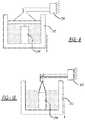
- FIG. 8is a schematic cross-sectional view of the vertically movable build chamber of FIG. 7 depicting a fixed material dispensing head;
- FIG. 9is a schematic cross-sectional view of the vertically movable build chamber of FIG. 7 depicting a fixed material scraper.
- FIG. 10is a schematic cross-sectional view of the vertically movable build chamber of FIG. 7 depicting a fixed laser device.
- an exemplary high throughput additive manufacturing system 10is shown having an annular, rotating powder bed build chamber 12 .
- the additive manufacturing system 10is capable of producing workpieces 14 at high volumes by enabling continuous operation of a high powered laser area scanning system, as will be described in greater detail below with respect to the various embodiments.
- the additive manufacturing system 10includes the annular, rotating powder bed build chamber 12 , a high power laser 16 arranged centrally within the build chamber 12 , a material dispensing head 18 for depositing layers of powder material within the build chamber 12 , and a scraper blade 20 for removing excess material deposited by the material dispensing head 18 .
- the annular, rotating design for the build chamber 12allows for high throughput capability of the laser system by eliminating any delay due to laser interruption during powder re-coating.
- the annular build chamber 12may be provided at a fixed height, may be vertically movable, or may be provided with movable sections, as will be further described below.
- the laser 16 , material dispensing head 18 , and scraper blade 20may be vertically movable with respect to the chamber 12 or may be fixed from vertical movement with respect to the chamber 12 .
- the material dispensing head 18deposits a powder material (e.g., metallic, polymeric, ceramic) onto an upper surface 22 of the build chamber 12 in order to construct a solid three-dimensional (3D) object.
- a powder materiale.g., metallic, polymeric, ceramic
- the scraper blade 20removes excess material from the upper surface 22 of the build chamber 12 , prior to entering a sintering zone 24 within the build chamber 12 .
- the sintering zone 24corresponds to an area within the build chamber 12 where a high power area scanning laser and/or single point lasers, collectively laser 16 , can raster scan the material layer in order to sinter the material in an arrangement corresponding to an incremental layer of the final workpiece 14 .
- the material dispensing head 18typically deposits layer upon layer of material, gradually adding object details for building the 3D object representation (i.e., workpiece 14 ), while the laser 16 sinters each layer to the previous material layer in order to form the final workpiece 14 .
- the build chamber 12is a rotating ring of powder, wherein each full rotation of the build chamber 12 adds another layer of powder (e.g., about 0.025-0.050 mm) to the workpiece 14 . As such, rotation of the build chamber 12 will correspond to the number of material layers required for the tallest workpiece 14 provided.
- alternate workpiece designse.g., workpiece 14 , workpiece 26 , workpiece 28 , workpiece 30
- workpiece 14may be manufactured concurrently in the build chamber 12 , such that any number of workpieces may be manufactured in a batch process.
- the additive manufacturing system 10may also operate with no workpieces within a particular section of the build chamber 12 . In this case, if a section of the build chamber 12 did not have a workpiece, the section would remain at a “full position” and the scraper blade 20 would push excess powder material along to the next section of the build chamber 12 having a workpiece.
- the laser 16is allowed to continuously raster scan the powder at the sintering zone 24 , without interruption, until the workpieces are finalized.
- a high speed mirror galvanometermay also be used to raster scan the laser area in a local region (e.g., 300 mm 2 ) within the sintering zone 24 .
- the laser 16may also be a plurality of lasers working in series or in parallel. In one example, an area scanning laser and a point laser may be used to first outline a workpiece and then complete the laser sintering of the interior portions.
- the rotational speed of the build chamber 12may be computer controlled (e.g., via controller 32 ) in order to correspond with the scanning speed of the laser 16 and, as such, may vary throughout the process depending upon workpiece complexity.
- the build chamber 12may also be sealed (e.g., vacuum or inert gas) to remove any effects from the external environment on the powder materials.
- a single material dispensing head 18 and scraper blade 20are described and shown, it is also contemplated to provide multiple powder delivery stages and/or multiple scraper blades, as needed, to distribute powder evenly at a high speed. Additional scrapers arranged about the build chamber may also be advantageous for collecting spatter or powder nuggets for removal prior to application of the next material layer.
- an exemplary additive manufacturing system 100may include a build chamber 112 having a plurality of individually movable, build plate ball screw elevators 134 .
- the additive manufacturing system 100is similar to the additive manufacturing system 10 , and therefore, like features will be described with like reference numbers.
- the build plate ball screw elevators 134may each have an individual ball screw system 136 for lowering or raising a corresponding build plate 138 over a distance equal to the height of the tallest workpiece to be produced in the build chamber 112 . In this way, material waste at the top of the chamber can be omitted for shorter workpieces. In other words, individualized movement of each of the build plates 138 permits operation without the necessity for equal filling of the volume of the build chamber 112 .
- the additive manufacturing system 100may be used to manufacture a system of workpieces 114 , 126 , 128 , 130 having various configurations and/or heights.
- the individual build plates 138 corresponding to each workpiece 114 , 126 , 128 , 130may be moved to a position corresponding to the vertical height of the tallest workpiece (e.g., workpiece 114 ) through movement of the ball screw system 136 .
- a material dispensing head 118dispenses a powder material onto the build plates 138 .
- a scraper blade 120removes excess material from the build plate 138 as the build plate 138 rotates in order to scrape material to the correct height, prior to the build plate 138 entering a sintering zone.
- a laser 116raster scans a single layer of a workpiece 114 , 126 , 128 , or 130 .
- the ball screw system 136gradually moves each of the build plates 138 downwardly for receipt of the next layer of powder material expended from the material dispensing head 118 . Downward movement ceases for each workpiece after the individual workpiece is completed, while taller workpieces continue to build, thereby preventing waste of powder on top of finished workpieces.
- build plate ball screw elevators 134have been described as having an individual build plate 138 corresponding to each workpiece 114 , 126 , 128 , 130 , it should be understood that multiple workpieces 140 , 142 , 144 could also be manufactured on a single build plate 138 .
- build plates 138can be exchanged during use to provide ease in workpiece management. In this way, the build plates 138 can serve as workpiece holding pallets, which may be removed from the additive manufacturing system 100 after building and conveniently moved to another step in the manufacturing process (e.g., heat treatment, machining).
- Build plate exchangealso provides the ability to manufacture additional workpieces sequentially during the pendency of a tall workpiece build (e.g., height of first workpiece is greater than additive height of second and third workpieces). In this way, cycle time for the system can be effectively reduced. It should also be understood that while the individual build plates 138 are described as being raised/lowered by a ball screw configuration, other raising/lowering devices may be used (e.g., pistons).
- an alternate additive manufacturing system 200may be used to manufacture workpieces 214 , 226 , 228 , 230 having various configurations and/or heights.
- the additive manufacturing system 200is similar to the additive manufacturing system 10 , and therefore, like features will be described with like reference numbers.
- the additive manufacturing system 200includes a fixed height, annular, rotating powder bed build chamber 212 , a vertically movable high power laser 216 arranged centrally within the build chamber 212 , a vertically movable material dispensing head 218 for depositing layers of powder material within the build chamber 212 , and a vertically movable scraper blade 220 for removing excess material deposited by the material dispensing head 218 .
- the annular build chamber 212has a fixed height, while the powder delivery system (i.e., material dispensing head 218 , scraper blade 220 ) and laser 216 incrementally raise in height (one layer per revolution) as the process proceeds.
- the powder delivery systemi.e., material dispensing head 218 , scraper blade 220
- laser 216incrementally raise in height (one layer per revolution) as the process proceeds.
- the laser 216continuously raster scans the powder at the sintering zone 224 , without interruption, until the workpieces are finalized.
- the rotational speed of the build chamber 212 and/or the height adjustment of the laser 216 , material dispensing head 218 , and scraper blade 220may be computer controlled (e.g., via controller 232 ) in order to correspond with the scanning speed of the laser 216 and, as such, may vary throughout the process depending upon workpiece complexity.
- the material dispensing head 218continuously dispenses a powder material into the build chamber 212 upon rotation thereof (see FIG. 4 ).
- the scraper blade 220removes excess material as the build chamber 212 rotates in order to provide material at the correct height, prior to the material entering the sintering zone 224 (see FIG. 5 ).
- the laser 216raster scans a single layer of a workpiece 214 , 226 , 228 , or 230 (see FIG. 6 ).
- the controller 232gradually moves each of the laser 216 , material dispensing head 218 , and scraper blade 220 upwardly for manipulating the next layer of powder material expended from the material dispensing head 218 .
- the rotational and linear motions of the additive manufacturing systemmay be separated by coordinating programmable linear actuators.
- the powder delivery systemi.e., material dispensing head 218 , scraper blade 220
- laser 216can be incrementally raised for each layer.
- the rotational motion of the build chamber 212could be managed by a separate programmable rotational axis.
- an alternate additive manufacturing system 300may be used to manufacture workpieces 314 , 326 , 328 , 330 having various configurations and/or heights.
- the additive manufacturing system 300is similar to the additive manufacturing system 10 , and therefore, like features will be described with like reference numbers.
- the additive manufacturing system 300includes a vertically movable, annular, rotating powder bed build chamber 312 , a fixed high power laser 316 arranged centrally within the build chamber 312 , a fixed material dispensing head 318 for depositing layers of powder material within the build chamber 312 , and a fixed scraper blade 320 for removing excess material deposited by the material dispensing head 318 .
- the annular build chamber 312may incrementally lower in height (one layer per bed revolution), while the powder delivery system (i.e., material dispensing head 318 , scraper blade 320 ) and laser 316 are fixed as the process proceeds.
- the laser 316may continuously raster scan the powder at the sintering zone 324 , without interruption, until the workpieces 314 , 326 , 328 , or 330 are finalized.
- the rotational speed and/or the height adjustment of the build chamber 312may be computer controlled (e.g., via controller 332 ) in order to correspond with the scanning speed of the laser 316 and, as such, may vary throughout the process depending upon workpiece complexity.
- the material dispensing head 318continuously dispenses a powder material into the build chamber 312 upon rotation thereof (see FIG. 8 ).
- the scraper blade 320removes excess material as the build chamber 312 rotates in order to provide material at the correct height, prior to the material entering the sintering zone 324 (see FIG. 9 ).
- the laser 316raster scans a single layer of the workpieces 314 , 326 , 328 , 330 (see FIG. 10 ).
- the controller 332gradually moves the build chamber 312 downwardly for manipulating the next layer of powder material expended from the material dispensing head 318 .
- a centrifugal forcemay be created due to the rotational speeds of the build chamber, which may, in turn, improve packing forces and packing density of the powder.
- inclining the upper surface of the build chambermay be necessary to offset the centrifugal forces and balance gravity to prevent powder shifting.
- the build chambercould remain stationary with a rotatable powder delivery and laser system.
- both the build chamber and the powder delivery/laser systemmay be movable at differing opposing rates in order to optimize the process.
- the workpieces manufactured in the exemplary embodimentscan be formed with a single material during the additive manufacturing process or can be designed as a graded material structure with different material(s) presented at the various layers.
- the embodiments provideddescribe all rotational motion as occurring at the build chamber; however, a stationary build chamber and rotationally movable laser, material dispensing head, and scraper blade is also contemplated. Additionally, the build chamber, laser, material dispensing head, and/or scraper blade can each rotate or move independently in the same or in opposite directions.
- the build chambersmay also revolve on an inclined plane (e.g., through a large screw and nut system) in order to create the simultaneous circular motion of the machine with a small linear step height each layer.
- an inclined planee.g., through a large screw and nut system
Landscapes
- Engineering & Computer Science (AREA)
- Chemical & Material Sciences (AREA)
- Materials Engineering (AREA)
- Manufacturing & Machinery (AREA)
- Physics & Mathematics (AREA)
- Optics & Photonics (AREA)
- Mechanical Engineering (AREA)
- Health & Medical Sciences (AREA)
- General Health & Medical Sciences (AREA)
- Toxicology (AREA)
- Plasma & Fusion (AREA)
- Automation & Control Theory (AREA)
- Ceramic Engineering (AREA)
- Powder Metallurgy (AREA)
Abstract
Description
Claims (10)
Priority Applications (3)
| Application Number | Priority Date | Filing Date | Title |
|---|---|---|---|
| US15/497,832US11007713B2 (en) | 2017-04-26 | 2017-04-26 | High throughput additive manufacturing system |
| CN201810335441.5ACN108790152B (en) | 2017-04-26 | 2018-04-16 | High-throughput additive manufacturing system |
| DE102018109737.9ADE102018109737A1 (en) | 2017-04-26 | 2018-04-23 | High throughput additive manufacturing system |
Applications Claiming Priority (1)
| Application Number | Priority Date | Filing Date | Title |
|---|---|---|---|
| US15/497,832US11007713B2 (en) | 2017-04-26 | 2017-04-26 | High throughput additive manufacturing system |
Publications (2)
| Publication Number | Publication Date |
|---|---|
| US20180311731A1 US20180311731A1 (en) | 2018-11-01 |
| US11007713B2true US11007713B2 (en) | 2021-05-18 |
Family
ID=63797235
Family Applications (1)
| Application Number | Title | Priority Date | Filing Date |
|---|---|---|---|
| US15/497,832Expired - Fee RelatedUS11007713B2 (en) | 2017-04-26 | 2017-04-26 | High throughput additive manufacturing system |
Country Status (3)
| Country | Link |
|---|---|
| US (1) | US11007713B2 (en) |
| CN (1) | CN108790152B (en) |
| DE (1) | DE102018109737A1 (en) |
Cited By (3)
| Publication number | Priority date | Publication date | Assignee | Title |
|---|---|---|---|---|
| US20210152062A1 (en)* | 2018-08-02 | 2021-05-20 | American Axle & Manufacturing, Inc. | System And Method For Additive Manufacturing |
| US11273496B2 (en)* | 2018-04-16 | 2022-03-15 | Panam 3D Llc | System and method for rotational 3D printing |
| US20220194004A1 (en)* | 2019-04-17 | 2022-06-23 | DP Polar GmbH | Method for Producing at Least One Solid-Body Layer in Accordance With Predetermined Geometry Data |
Families Citing this family (23)
| Publication number | Priority date | Publication date | Assignee | Title |
|---|---|---|---|---|
| EP3554836B1 (en)* | 2016-12-13 | 2021-01-27 | Stratasys, Inc. | Rotary silo additive manufacturing system |
| US10821514B2 (en)* | 2017-05-31 | 2020-11-03 | General Electric Company | Apparatus and method for continuous additive manufacturing |
| US11224940B2 (en)* | 2018-02-05 | 2022-01-18 | General Electric Company | Powder bed containment systems for use with rotating direct metal laser melting systems |
| US11141818B2 (en) | 2018-02-05 | 2021-10-12 | General Electric Company | Rotating direct metal laser melting systems and methods of operation |
| EP3566854B1 (en)* | 2018-05-07 | 2021-09-15 | CL Schutzrechtsverwaltungs GmbH | Apparatus for additively manufacturing three-dimensional objects |
| US11872763B2 (en)* | 2018-07-12 | 2024-01-16 | Hewlett-Packard Development Company, L.P. | Supplying material to an additive manufacturing platform |
| DE102018212019A1 (en)* | 2018-07-19 | 2020-01-23 | MTU Aero Engines AG | Process for applying a material |
| US11426818B2 (en) | 2018-08-10 | 2022-08-30 | The Research Foundation for the State University | Additive manufacturing processes and additively manufactured products |
| DE102018129022A1 (en)* | 2018-11-19 | 2020-05-20 | AMCM GmbH | Radial flow over a construction field |
| CN111070683B (en)* | 2018-12-20 | 2021-05-07 | 上海微电子装备(集团)股份有限公司 | 3D printing powder laying system, 3D printing device and 3D printing powder laying method |
| CN109483880A (en)* | 2018-12-28 | 2019-03-19 | 源秩科技(上海)有限公司 | Spreading system and method |
| US20220055115A1 (en)* | 2019-03-04 | 2022-02-24 | SLM Solutions Group AG | Device and method for producing a three-dimensional workpiece |
| US11712057B2 (en)* | 2020-02-10 | 2023-08-01 | Purdue Research Foundation | Convergent manufacturing platform capable of additive-subtractive-assembly processes and systems |
| US11590575B2 (en) | 2020-04-07 | 2023-02-28 | GM Global Technology Operations LLC | Metal condensate control during additive manufacturing |
| CN111390170B (en)* | 2020-04-17 | 2021-06-18 | 中国科学院福建物质结构研究所 | Climbing type large-size rotating member laser 3D printing equipment and printing method |
| US11155028B1 (en)* | 2020-04-24 | 2021-10-26 | Sprintray Inc. | Apparatus and method for three-dimensional printing |
| DE102020116972A1 (en) | 2020-06-26 | 2021-12-30 | Fraunhofer-Gesellschaft zur Förderung der angewandten Forschung eingetragener Verein | Process and device for additive manufacturing |
| US12109613B2 (en)* | 2021-04-01 | 2024-10-08 | Battelle Savannah River Alliance, Llc | Additive manufacturing systems and associated methods |
| CN113953538B (en)* | 2021-09-29 | 2022-10-25 | 西安交通大学 | Annular powder jar vibration material disk forming device |
| CN113664219B (en)* | 2021-10-23 | 2022-01-18 | 北京煜鼎增材制造研究院有限公司 | High-temperature titanium alloy material high-flux preparation method based on laser in-situ metallurgy |
| CN115921909A (en)* | 2022-06-16 | 2023-04-07 | 亚洲新材料(北京)有限公司 | Laser selective melting equipment and forming method for unsupported forming materials |
| GB202210688D0 (en)* | 2022-07-21 | 2022-09-07 | Rolls Royce Plc | Apparatus and method |
| CN116422908B (en)* | 2023-06-13 | 2023-08-29 | 济南大学 | A SLM additive manufacturing device and method for multi-material gradient molding |
Citations (26)
| Publication number | Priority date | Publication date | Assignee | Title |
|---|---|---|---|---|
| US5639070A (en)* | 1986-10-17 | 1997-06-17 | Board Of Regents, The University Of Texas System | Method for producing parts by selective sintering |
| US20030028278A1 (en)* | 2001-07-31 | 2003-02-06 | 3D Systems, Inc. | Selective laser sintering with interleaved fill scan |
| US20030205851A1 (en)* | 2002-05-03 | 2003-11-06 | Bego Medical Ag | Device and method for producing freely formed products |
| US20040265413A1 (en)* | 2003-05-23 | 2004-12-30 | Z Corporation | Apparatus and methods for 3D printing |
| US20060108712A1 (en)* | 2002-08-02 | 2006-05-25 | Eos Gmbh Electro Optical Systems | Device and method for producing a three-dimensional object by means of a generative production method |
| US7141207B2 (en) | 2004-08-30 | 2006-11-28 | General Motors Corporation | Aluminum/magnesium 3D-Printing rapid prototyping |
| US20070029698A1 (en) | 2003-09-11 | 2007-02-08 | Rynerson Michael L | Layered manufactured articles having small-diameter fluid conduction vents and method of making same |
| US20070063372A1 (en)* | 2005-09-19 | 2007-03-22 | Nielsen Jeffrey A | Systems and methods of solid freeform fabrication with interchangeable powder bins |
| US20080109102A1 (en)* | 2003-06-05 | 2008-05-08 | The University Of Liverpool | Apparatus For Manufacturing Three Dimensional Items |
| US20120211155A1 (en)* | 2009-08-25 | 2012-08-23 | Bego Medical Gmbh | Device and Method for Generative Production |
| US20130264750A1 (en)* | 2010-09-23 | 2013-10-10 | Siemens Aktiengesellschaft | Method for selective laser sintering and system for selective laser sintering suitable for said method |
| US20140191439A1 (en)* | 2013-01-04 | 2014-07-10 | New York University | Continuous Feed 3D Manufacturing |
| US20150057784A1 (en) | 2013-08-21 | 2015-02-26 | Microsoft Corporation | Optimizing 3d printing using segmentation or aggregation |
| US20150061190A1 (en) | 2013-09-02 | 2015-03-05 | Big GimicArt Ltd. | Large Shells Manufacturing Apparatus |
| US20150328838A1 (en) | 2014-05-13 | 2015-11-19 | Massachusetts Institute Of Technology | Systems, devices, and methods for three-dimensional printing |
| US20160193695A1 (en)* | 2012-07-27 | 2016-07-07 | Aerojet Rocketdyne Of De, Inc. | Solid axisymmetric powder bed for selective laser melting |
| WO2016142930A1 (en) | 2015-03-12 | 2016-09-15 | Massivit 3D Printing Technologies Ltd. | A machine for 3d objects manufacture |
| US20160368050A1 (en)* | 2015-06-19 | 2016-12-22 | General Electric Company | Additive manufacturing apparatus and method for large components |
| US20170050386A1 (en)* | 2014-04-30 | 2017-02-23 | Nederlandse Organisatie Voor Toegepast-Natuurwetenschappelijk Onderzoek Tno | Method and production line for making tangible products by layerwise manufacturing |
| GB2543305A (en)* | 2015-10-14 | 2017-04-19 | Rolls Royce Plc | Apparatus for building a component |
| US20170120537A1 (en)* | 2015-10-30 | 2017-05-04 | Seurat Technologies, Inc. | Chamber systems for additive manufacturing |
| US20170190112A1 (en)* | 2016-01-04 | 2017-07-06 | Caterpillar Inc. | 3D Printing |
| US20170341180A1 (en)* | 2016-04-29 | 2017-11-30 | Nuburu, Inc. | Visible laser additive manufacturing |
| US20180085856A1 (en)* | 2016-09-29 | 2018-03-29 | Safran Aircraft Engines | Device for fabricating annular pieces by selectively melting powder, the device including a powder wiper |
| US20180111322A1 (en)* | 2015-05-11 | 2018-04-26 | Dp Digital Solutions Gmbh | Device and Method for Applying Flowable Material to a Substratum That Can Be Rotated About an Axis of Rotation |
| US20180200835A1 (en)* | 2017-01-13 | 2018-07-19 | GM Global Technology Operations LLC | Powder bed fusion system with point and area scanning laser beams |
- 2017
- 2017-04-26USUS15/497,832patent/US11007713B2/ennot_activeExpired - Fee Related
- 2018
- 2018-04-16CNCN201810335441.5Apatent/CN108790152B/enactiveActive
- 2018-04-23DEDE102018109737.9Apatent/DE102018109737A1/ennot_activeWithdrawn
Patent Citations (26)
| Publication number | Priority date | Publication date | Assignee | Title |
|---|---|---|---|---|
| US5639070A (en)* | 1986-10-17 | 1997-06-17 | Board Of Regents, The University Of Texas System | Method for producing parts by selective sintering |
| US20030028278A1 (en)* | 2001-07-31 | 2003-02-06 | 3D Systems, Inc. | Selective laser sintering with interleaved fill scan |
| US20030205851A1 (en)* | 2002-05-03 | 2003-11-06 | Bego Medical Ag | Device and method for producing freely formed products |
| US20060108712A1 (en)* | 2002-08-02 | 2006-05-25 | Eos Gmbh Electro Optical Systems | Device and method for producing a three-dimensional object by means of a generative production method |
| US20040265413A1 (en)* | 2003-05-23 | 2004-12-30 | Z Corporation | Apparatus and methods for 3D printing |
| US20080109102A1 (en)* | 2003-06-05 | 2008-05-08 | The University Of Liverpool | Apparatus For Manufacturing Three Dimensional Items |
| US20070029698A1 (en) | 2003-09-11 | 2007-02-08 | Rynerson Michael L | Layered manufactured articles having small-diameter fluid conduction vents and method of making same |
| US7141207B2 (en) | 2004-08-30 | 2006-11-28 | General Motors Corporation | Aluminum/magnesium 3D-Printing rapid prototyping |
| US20070063372A1 (en)* | 2005-09-19 | 2007-03-22 | Nielsen Jeffrey A | Systems and methods of solid freeform fabrication with interchangeable powder bins |
| US20120211155A1 (en)* | 2009-08-25 | 2012-08-23 | Bego Medical Gmbh | Device and Method for Generative Production |
| US20130264750A1 (en)* | 2010-09-23 | 2013-10-10 | Siemens Aktiengesellschaft | Method for selective laser sintering and system for selective laser sintering suitable for said method |
| US20160193695A1 (en)* | 2012-07-27 | 2016-07-07 | Aerojet Rocketdyne Of De, Inc. | Solid axisymmetric powder bed for selective laser melting |
| US20140191439A1 (en)* | 2013-01-04 | 2014-07-10 | New York University | Continuous Feed 3D Manufacturing |
| US20150057784A1 (en) | 2013-08-21 | 2015-02-26 | Microsoft Corporation | Optimizing 3d printing using segmentation or aggregation |
| US20150061190A1 (en) | 2013-09-02 | 2015-03-05 | Big GimicArt Ltd. | Large Shells Manufacturing Apparatus |
| US20170050386A1 (en)* | 2014-04-30 | 2017-02-23 | Nederlandse Organisatie Voor Toegepast-Natuurwetenschappelijk Onderzoek Tno | Method and production line for making tangible products by layerwise manufacturing |
| US20150328838A1 (en) | 2014-05-13 | 2015-11-19 | Massachusetts Institute Of Technology | Systems, devices, and methods for three-dimensional printing |
| WO2016142930A1 (en) | 2015-03-12 | 2016-09-15 | Massivit 3D Printing Technologies Ltd. | A machine for 3d objects manufacture |
| US20180111322A1 (en)* | 2015-05-11 | 2018-04-26 | Dp Digital Solutions Gmbh | Device and Method for Applying Flowable Material to a Substratum That Can Be Rotated About an Axis of Rotation |
| US20160368050A1 (en)* | 2015-06-19 | 2016-12-22 | General Electric Company | Additive manufacturing apparatus and method for large components |
| GB2543305A (en)* | 2015-10-14 | 2017-04-19 | Rolls Royce Plc | Apparatus for building a component |
| US20170120537A1 (en)* | 2015-10-30 | 2017-05-04 | Seurat Technologies, Inc. | Chamber systems for additive manufacturing |
| US20170190112A1 (en)* | 2016-01-04 | 2017-07-06 | Caterpillar Inc. | 3D Printing |
| US20170341180A1 (en)* | 2016-04-29 | 2017-11-30 | Nuburu, Inc. | Visible laser additive manufacturing |
| US20180085856A1 (en)* | 2016-09-29 | 2018-03-29 | Safran Aircraft Engines | Device for fabricating annular pieces by selectively melting powder, the device including a powder wiper |
| US20180200835A1 (en)* | 2017-01-13 | 2018-07-19 | GM Global Technology Operations LLC | Powder bed fusion system with point and area scanning laser beams |
Non-Patent Citations (2)
| Title |
|---|
| Wikipedia, "Laser scanning", 2016, https://en.wikipedia.org/wiki/Laser_scanning (Year: 2016).* |
| Wikipedia, "Mirror galvanometer", 2016, https://en.wikipedia.org/wiki/Mirror_galvanometer (Year: 2016).* |
Cited By (5)
| Publication number | Priority date | Publication date | Assignee | Title |
|---|---|---|---|---|
| US11273496B2 (en)* | 2018-04-16 | 2022-03-15 | Panam 3D Llc | System and method for rotational 3D printing |
| US20210152062A1 (en)* | 2018-08-02 | 2021-05-20 | American Axle & Manufacturing, Inc. | System And Method For Additive Manufacturing |
| US12023736B2 (en)* | 2018-08-02 | 2024-07-02 | American Axle & Manufacturing, Inc. | Method of additive manufacturing using a rotary table |
| US20220194004A1 (en)* | 2019-04-17 | 2022-06-23 | DP Polar GmbH | Method for Producing at Least One Solid-Body Layer in Accordance With Predetermined Geometry Data |
| US12017412B2 (en)* | 2019-04-17 | 2024-06-25 | 3D Systems Gmbh | Method for producing at least one solid-body layer in accordance with predetermined geometry data |
Also Published As
| Publication number | Publication date |
|---|---|
| CN108790152B (en) | 2021-03-23 |
| US20180311731A1 (en) | 2018-11-01 |
| DE102018109737A1 (en) | 2018-10-31 |
| CN108790152A (en) | 2018-11-13 |
Similar Documents
| Publication | Publication Date | Title |
|---|---|---|
| US11007713B2 (en) | High throughput additive manufacturing system | |
| US8172562B2 (en) | Device and method for producing a three-dimensional object by means of a generative production method | |
| EP3106288B1 (en) | Additive manufacturing apparatus and method for large components | |
| US10029417B2 (en) | Articulating build platform for laser additive manufacturing | |
| US10835956B2 (en) | Hopper for powder bed fusion additive manufacturing | |
| JP5582923B2 (en) | Apparatus and method for continuous manufacturing | |
| EP2319641B1 (en) | Method to apply multiple materials with selective laser melting on a 3D article | |
| EP3124140B1 (en) | Apparatus with a build module and production method for additive manufacturing | |
| US10625338B2 (en) | Method for forming brace structures for additive manufacturing | |
| US10723071B2 (en) | Device and method for generatively producing a three-dimensional object | |
| US20170072466A1 (en) | Selectively openable support platen for additive manufacturing | |
| CN110494238A (en) | The increasing material manufacturing carried out using the heavy applicator with the heavy applicator blade that can be replaced in situ | |
| US20190143406A1 (en) | Additive manufacturing apparatus and method for large components | |
| JP2006526524A (en) | Three-dimensional article manufacturing equipment | |
| US10821511B2 (en) | Additive manufacturing apparatus and method for large components | |
| US20170072467A1 (en) | Fabrication of base plate, fabrication of enclosure, and fabrication of support posts in additive manufacturing | |
| RU2674588C2 (en) | Method for additive welding and melting manufacture of three-dimensional products and installation for its implementation | |
| US20190054529A1 (en) | Method and machines for manufacturing at least one piece made of at least one ceramic and/or metallic material by the technique of additive manufacturing | |
| CN112188962A (en) | Method of preparing powder bed deposited additive manufacturing platform upper surface | |
| US20200223011A1 (en) | Installation for the Powder-Bed-Based Additive Manufacturing of a Workpiece, Comprising Multiple Metering Devices for Different Types of Powder | |
| KR20200019279A (en) | 3d printing method for easy removal of support | |
| CN114585496A (en) | Apparatus and method for additive manufacturing | |
| US11478983B2 (en) | Additive manufacturing apparatus and method for large components | |
| RU152914U1 (en) | DEVICE FOR PRODUCING GRADIENT MATERIALS FROM POWDER SYSTEMS | |
| KR20190019852A (en) | Method and machine for manufacturing pieces made of ceramic or metallic material by the technique of additive manufacturing |
Legal Events
| Date | Code | Title | Description |
|---|---|---|---|
| AS | Assignment | Owner name:GM GLOBAL TECHNOLOGY OPERATIONS LLC, MICHIGAN Free format text:ASSIGNMENT OF ASSIGNORS INTEREST;ASSIGNORS:SPICER, JOHN P;NOLTE, JASON J;PERRY, THOMAS A;AND OTHERS;SIGNING DATES FROM 20170410 TO 20170421;REEL/FRAME:042593/0958 | |
| STPP | Information on status: patent application and granting procedure in general | Free format text:NON FINAL ACTION MAILED | |
| STPP | Information on status: patent application and granting procedure in general | Free format text:RESPONSE TO NON-FINAL OFFICE ACTION ENTERED AND FORWARDED TO EXAMINER | |
| STPP | Information on status: patent application and granting procedure in general | Free format text:FINAL REJECTION MAILED | |
| STPP | Information on status: patent application and granting procedure in general | Free format text:RESPONSE AFTER FINAL ACTION FORWARDED TO EXAMINER | |
| STPP | Information on status: patent application and granting procedure in general | Free format text:ADVISORY ACTION MAILED | |
| STPP | Information on status: patent application and granting procedure in general | Free format text:DOCKETED NEW CASE - READY FOR EXAMINATION | |
| STPP | Information on status: patent application and granting procedure in general | Free format text:NON FINAL ACTION MAILED | |
| STPP | Information on status: patent application and granting procedure in general | Free format text:FINAL REJECTION MAILED | |
| STPP | Information on status: patent application and granting procedure in general | Free format text:NOTICE OF ALLOWANCE MAILED -- APPLICATION RECEIVED IN OFFICE OF PUBLICATIONS | |
| STPP | Information on status: patent application and granting procedure in general | Free format text:PUBLICATIONS -- ISSUE FEE PAYMENT VERIFIED | |
| STCF | Information on status: patent grant | Free format text:PATENTED CASE | |
| FEPP | Fee payment procedure | Free format text:MAINTENANCE FEE REMINDER MAILED (ORIGINAL EVENT CODE: REM.); ENTITY STATUS OF PATENT OWNER: LARGE ENTITY | |
| LAPS | Lapse for failure to pay maintenance fees | Free format text:PATENT EXPIRED FOR FAILURE TO PAY MAINTENANCE FEES (ORIGINAL EVENT CODE: EXP.); ENTITY STATUS OF PATENT OWNER: LARGE ENTITY | |
| STCH | Information on status: patent discontinuation | Free format text:PATENT EXPIRED DUE TO NONPAYMENT OF MAINTENANCE FEES UNDER 37 CFR 1.362 | |
| FP | Lapsed due to failure to pay maintenance fee | Effective date:20250518 |