US11006555B2 - Shield member, shield member-attached electric wire, intermediate product for shield member, and method for producing shield member - Google Patents
Shield member, shield member-attached electric wire, intermediate product for shield member, and method for producing shield memberDownload PDFInfo
- Publication number
- US11006555B2 US11006555B2US16/319,021US201716319021AUS11006555B2US 11006555 B2US11006555 B2US 11006555B2US 201716319021 AUS201716319021 AUS 201716319021AUS 11006555 B2US11006555 B2US 11006555B2
- Authority
- US
- United States
- Prior art keywords
- shield
- drain wire
- shield member
- shield portion
- wire
- Prior art date
- Legal status (The legal status is an assumption and is not a legal conclusion. Google has not performed a legal analysis and makes no representation as to the accuracy of the status listed.)
- Active
Links
- 239000013067intermediate productSubstances0.000titleclaimsdescription30
- 238000004519manufacturing processMethods0.000titleclaimsdescription17
- 238000005520cutting processMethods0.000claimsabstractdescription13
- 239000004745nonwoven fabricSubstances0.000claimsdescription26
- 238000000034methodMethods0.000claimsdescription16
- 239000000463materialSubstances0.000claimsdescription15
- 239000000758substrateSubstances0.000claimsdescription12
- 239000000835fiberSubstances0.000description20
- 239000002184metalSubstances0.000description11
- 229920005989resinPolymers0.000description7
- 239000011347resinSubstances0.000description7
- 239000004020conductorSubstances0.000description3
- 238000010586diagramMethods0.000description3
- 238000007747platingMethods0.000description2
- 238000003825pressingMethods0.000description2
- 238000004080punchingMethods0.000description2
- 239000004840adhesive resinSubstances0.000description1
- 229920006223adhesive resinPolymers0.000description1
- 239000011230binding agentSubstances0.000description1
- 239000011248coating agentSubstances0.000description1
- 238000000576coating methodMethods0.000description1
- 239000000470constituentSubstances0.000description1
- 230000000694effectsEffects0.000description1
- 239000011888foilSubstances0.000description1
- 238000009434installationMethods0.000description1
Images


Classifications
- H—ELECTRICITY
- H05—ELECTRIC TECHNIQUES NOT OTHERWISE PROVIDED FOR
- H05K—PRINTED CIRCUITS; CASINGS OR CONSTRUCTIONAL DETAILS OF ELECTRIC APPARATUS; MANUFACTURE OF ASSEMBLAGES OF ELECTRICAL COMPONENTS
- H05K9/00—Screening of apparatus or components against electric or magnetic fields
- H05K9/0073—Shielding materials
- H05K9/0098—Shielding materials for shielding electrical cables
- H—ELECTRICITY
- H01—ELECTRIC ELEMENTS
- H01B—CABLES; CONDUCTORS; INSULATORS; SELECTION OF MATERIALS FOR THEIR CONDUCTIVE, INSULATING OR DIELECTRIC PROPERTIES
- H01B11/00—Communication cables or conductors
- H01B11/02—Cables with twisted pairs or quads
- H01B11/06—Cables with twisted pairs or quads with means for reducing effects of electromagnetic or electrostatic disturbances, e.g. screens
- H01B11/10—Screens specially adapted for reducing interference from external sources
- H01B11/1091—Screens specially adapted for reducing interference from external sources with screen grounding means, e.g. drain wires
- H—ELECTRICITY
- H01—ELECTRIC ELEMENTS
- H01B—CABLES; CONDUCTORS; INSULATORS; SELECTION OF MATERIALS FOR THEIR CONDUCTIVE, INSULATING OR DIELECTRIC PROPERTIES
- H01B13/00—Apparatus or processes specially adapted for manufacturing conductors or cables
- H01B13/22—Sheathing; Armouring; Screening; Applying other protective layers
- H—ELECTRICITY
- H01—ELECTRIC ELEMENTS
- H01B—CABLES; CONDUCTORS; INSULATORS; SELECTION OF MATERIALS FOR THEIR CONDUCTIVE, INSULATING OR DIELECTRIC PROPERTIES
- H01B9/00—Power cables
- H01B9/02—Power cables with screens or conductive layers, e.g. for avoiding large potential gradients
- H01B9/028—Power cables with screens or conductive layers, e.g. for avoiding large potential gradients with screen grounding means, e.g. drain wires
- H—ELECTRICITY
- H02—GENERATION; CONVERSION OR DISTRIBUTION OF ELECTRIC POWER
- H02G—INSTALLATION OF ELECTRIC CABLES OR LINES, OR OF COMBINED OPTICAL AND ELECTRIC CABLES OR LINES
- H02G3/00—Installations of electric cables or lines or protective tubing therefor in or on buildings, equivalent structures or vehicles
- H02G3/02—Details
- H02G3/04—Protective tubing or conduits, e.g. cable ladders or cable troughs
- H02G3/0462—Tubings, i.e. having a closed section
- H—ELECTRICITY
- H05—ELECTRIC TECHNIQUES NOT OTHERWISE PROVIDED FOR
- H05K—PRINTED CIRCUITS; CASINGS OR CONSTRUCTIONAL DETAILS OF ELECTRIC APPARATUS; MANUFACTURE OF ASSEMBLAGES OF ELECTRICAL COMPONENTS
- H05K9/00—Screening of apparatus or components against electric or magnetic fields
- H05K9/0073—Shielding materials
- H05K9/0081—Electromagnetic shielding materials, e.g. EMI, RFI shielding
- H05K9/0088—Electromagnetic shielding materials, e.g. EMI, RFI shielding comprising a plurality of shielding layers; combining different shielding material structure
- H—ELECTRICITY
- H05—ELECTRIC TECHNIQUES NOT OTHERWISE PROVIDED FOR
- H05K—PRINTED CIRCUITS; CASINGS OR CONSTRUCTIONAL DETAILS OF ELECTRIC APPARATUS; MANUFACTURE OF ASSEMBLAGES OF ELECTRICAL COMPONENTS
- H05K9/00—Screening of apparatus or components against electric or magnetic fields
- H05K9/0073—Shielding materials
- H05K9/0081—Electromagnetic shielding materials, e.g. EMI, RFI shielding
- H05K9/009—Electromagnetic shielding materials, e.g. EMI, RFI shielding comprising electro-conductive fibres, e.g. metal fibres, carbon fibres, metallised textile fibres, electro-conductive mesh, woven, non-woven mat, fleece, cross-linked
- B—PERFORMING OPERATIONS; TRANSPORTING
- B60—VEHICLES IN GENERAL
- B60R—VEHICLES, VEHICLE FITTINGS, OR VEHICLE PARTS, NOT OTHERWISE PROVIDED FOR
- B60R16/00—Electric or fluid circuits specially adapted for vehicles and not otherwise provided for; Arrangement of elements of electric or fluid circuits specially adapted for vehicles and not otherwise provided for
- B60R16/02—Electric or fluid circuits specially adapted for vehicles and not otherwise provided for; Arrangement of elements of electric or fluid circuits specially adapted for vehicles and not otherwise provided for electric constitutive elements
- B60R16/0207—Wire harnesses
- B60R16/0215—Protecting, fastening and routing means therefor
Definitions
- the present inventionrelates to a technique for shielding an electric wire.
- Patent Document 1discloses a wire harness in which a plurality of electric wires of a low-voltage system circuit and a plurality of electric wires of a high-voltage system circuit are provided separately, and the plurality of electric wires of the low-voltage system circuit and the plurality of electric wires of the high-voltage system circuit are sheathed using an insulating sheet and a shield sheet that are folded so as to separately envelop the entire outer circumference of the plurality of electric wires of the low-voltage system circuit and the plurality of electric wires of the high-voltage system circuit, whereby it is possible to prevent electromagnetic noise generated by the electric wires of the high-voltage system circuit from negatively affecting the low-voltage system circuit.
- a drain wire-attached shield membermay be produced by cutting a long drain wire-attached shield member to a desired adjusted length.
- the drain wireis held in the shield layer, and it is difficult to ground the shield sheet.
- an end portion of the drain wiremay be made free to facilitate connection by cutting the long drain wire-attached shield member to a length longer than the desired length and removing only an end portion of the shield portion while leaving the drain wire.
- the production yielddeteriorates by an amount corresponding to the amount the shield layer is cut.
- a shield memberincludes: a shield portion that can shield an electric wire; and a drain wire that includes a holding portion provided between a first end and a second end of the shield portion and held in the shield portion, and an extension portion continuous with the holding portion and extending outward from the shield portion, and in which at least a portion of the holding portion extends between the first end and the second end of the shield portion while having excess length.
- a shield member according to a second aspectis the shield member according to the first aspect, wherein the shield portion is formed using an electroconductive non-woven fabric as a material thereof, and the holding portion is passed through the non-woven fabric.
- a shield member according to a third aspectis the shield member according to the first aspect, wherein the shield portion is formed by stacking a plurality of substrates including a shield material, and the holding portion is sandwiched between the plurality of substrates.
- a shield member according to a fourth aspectis the shield member according to any one of the first to third aspects, wherein the holding portion extends in an undulating manner, and thus has excess length.
- a shield member-attached electric wire according to a fifth aspectincludes: the shield member according to any one of the first to fourth aspects; and an electric wire covered by the shield member.
- An intermediate product for a shield memberincludes: a shield portion that can shield an electric wire; and a drain wire that is provided between a first end and a second end of the shield portion, the drain wire extending between the first end and the second end of the shield portion while having excess length and being held in the shield portion such that an end portion of the drain wire can be drawn outward from the shield portion.
- a method for producing a shield member according to a seventh aspectincludes the steps of: (a) preparing a long shield member that includes a shield portion and a drain wire that is provided between a first end and a second end of the shield portion and extends between the first end and the second end of the shield portion while having excess length; (b) cutting the long shield member to a desired length so as to produce an intermediate product; and (c) drawing an end portion of the drain wire out of the intermediate product outward from the shield portion.
- the extension portioncan be formed by drawing the drain wire from the holding portion outward of the shield portion. Accordingly, when producing a shield member including a drain wire with a free end portion by cutting a long drain wire-attached shield member to a desired length, it is unnecessary to remove the shield portion while leaving only the drain wire, and thus the production yield can be improved.
- the drain wirecan be placed so as to extend along the shield portion while being connected to the shield portion.
- the drain wireis sandwiched between a plurality of substrates, the drain wire can be easily placed so as to extend along the shield portion while being connected to the shield portion.
- the drain wirecan be easily drawn out from the holding portion.
- the holding portionextends between the first end and the second end of the shield portion while having excess length, and it is therefore possible to draw the drain wire from the holding portion outward of the shield portion. Accordingly, when producing a shield member including a drain wire with a free end portion by cutting a long drain wire-attached shield member to a desired length, it is unnecessary to remove the shield portion while leaving only the drain wire, and thus the production yield can be improved.
- the drain wireextends between the first end and the second end of the shield portion while having excess length and is held in the shield portion such that an end portion of the drain wire can be drawn outward from the shield portion, and thus the drain wire can be drawn outward of the shield portion. Accordingly, when producing a shield member including a drain wire with a free end portion by cutting a long drain wire-attached shield member to a desired length, it is unnecessary to remove the shield portion while leaving only the drain wire, and thus the production yield can be improved.
- the methodincludes a step of drawing the drain wire outward of the shield portion from an intermediate product with a desired length obtained through cutting. Accordingly, in the intermediate product, it is unnecessary to remove the shield portion while leaving only the drain wire, and thus the production yield can be improved.
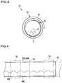
- FIG. 1is a plan view of a shield member according to an embodiment.
- FIG. 2is a cross-sectional view taken along the line II-II shown in FIG. 1 .
- FIG. 3is a front view of a shield member-attached electric wire according to an embodiment.
- FIG. 4is a diagram illustrating a method for producing a shield member according to an embodiment.
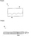
- FIG. 5is a plan view of an intermediate product for a shield member according to an embodiment.
- FIG. 6is a cross-sectional view of a shield member according to a variation.
- a descriptionwill be given of a shield member, a shield member-attached electric wire, an intermediate product for a shield member, and a method for producing a shield member according to an embodiment.
- FIG. 1is a plan view of a shield member 20 according to the embodiment.
- FIG. 2is a cross-sectional view taken along the line II-II shown in FIG. 1 .
- the shield member 20is a member that covers an electric wire 12 and shields the electric wire 12 (see FIG. 3 ).
- the shield member 20includes a shield portion 22 and a drain wire 30 .
- the shield portion 22is formed so as to be capable of shielding the electric wire 12 . That is, the shield portion 22 is formed such that an electroconductive member can cover the electric wire 12 .
- the length and the width of the shield portion 22are set as appropriate according to the electric wire 12 to which the shield portion 22 is to be attached. This example will be described assuming that the shield portion 22 is formed using an electroconductive non-woven fabric 24 as a material thereof.
- a known electroconductive non-woven fabric 24 including resin fibers and metal fiberscan be used as the non-woven fabric 24 .
- the metal fibersmay be fibers only made of metal, or fibers other than metal fibers such as resin fibers, with metal plating.
- the ratio of the resin fibers and the metal fibers that constitute the non-woven fabric 24is set as appropriate according to the shielding properties, ease of production, and the like.
- the method for forming a webmay be a dry method, a wet method, or a spunbonding method.
- the method for bonding webs togethermay be, for example, a needle punching method, or a thermal bonding method in which the resin fibers described above are made of a thermal adhesive resin, and functions as a binder that adhesively bonds fibers together.
- the drain wire 30is routed in the non-woven fabric 24 , and it is therefore preferable that the non-woven fabric 24 is a non-woven fabric in which the drain wire 30 routed therein is more reliably connected to the metal fibers.
- a non-woven fabricis formed by, for example, bonding a web made of resin fibers and a web made of metal fibers using a needle punching method. In this case, the fibers become entangled and bond to each other without the resin fibers adhering to each other, and thus the drain wire and the metal fibers can be more reliably electrically connected to each other.
- the shield portion 22is formed in the form of a sheet.
- the non-woven fabric 24is produced in the form of a sheet.
- a non-woven fabric 24 produced in the form of a sheetcan be used as the shield portion 22 .
- the shield portion 22may be formed in a cylindrical shape or the like.
- the shield portioncan be formed in a cylindrical shape by deforming a non-woven fabric 24 in the form of a sheet into a cylindrical shape and heat pressing the non-woven fabric 24 .
- the drain wire 30is a member for grounding the shield portion 22 . Accordingly, the drain wire 30 includes a conductor wire, and a portion of the drain wire 30 is connected to the shield portion 22 .
- the drain wire 30is a linear conductor without a coating, or in other words, a bare conductor wire.
- the drain wire 30is a twisted wire in which a plurality of thin strands are twisted together, but the drain wire 30 may be a single wire.
- a ground terminalmay be connected to an end portion of the drain wire 30 so as to connect the drain wire 30 to ground via the ground terminal.
- the drain wire 30includes a holding portion 32 and an extension portion 34 .
- the holding portion 32is provided between a first end and a second end of the shield portion 22 .
- the holding portion 32is present over the entire region extending from the first end to the second end of the shield portion 22 .
- the holding portion 32may be present in a region extending from the first end to the center of the shield portion 22 .
- the holding portion 32is held in the shield portion 22 .
- the holding portion 32is held while being electrically connected to the shield portion 22 .
- the holding portion 32may or may not be joined to the shield portion 22 .
- the holding portion 32is passed through the non-woven fabric 24 .
- the holding portion 32is held in the shield portion 22 without being joined to the shield portion 22 while being electrically connected to the shield portion 22 by, for example, passing the drain wire 30 through the non-woven fabric 24 whose fibers are relatively densely entangled with each other, or by heat pressing and compressing the non-woven fabric 24 through which the drain wire 30 is passed.
- the holding portion 32extends between the first end and the second end of the shield portion 22 while having excess length.
- the holding portion 32extends in an undulating manner, and thereby has excess length. While this is described later, the shield member 20 is produced by drawing the drain wire 30 out from an intermediate product 21 (see FIG. 5 ) in which the drain wire 30 does not extend outward from the shield portion 22 . At this time, the drain wire 30 has excess length in the intermediate product 21 , and the drain wire 30 is drawn out using the excess length.
- the excess length of the holding portion 32 in the shield member 20is a portion not used when the drain wire 30 is drawn out from the intermediate product 21 . That is, it can be said that the excess length in the shield member 20 is an indicator indicating that the shield member 20 was produced from the intermediate product 21 .
- the extension portion 34extends from the first end side of the shield portion 22 . That is, the drain wire 30 is drawn out from the first end side of the shield portion 22 . Accordingly, the height of the undulating shape is reduced on the first end side as compared with that on the second end side, and the excess length is smaller on the first end side.
- the extension portion 34is continuous with the holding portion 32 and extends outward from the shield portion 22 .
- the extension portion 34extends only from the first end portion of the holding portion 32 .
- the extension portion 34may also be drawn out from the second end side.
- the extension portion on the second end sidemay be joined and electrically connected to a member that requires ground connection.
- the length of the extension portionis set as appropriate according to the distance from the position at which the shield member 20 is provided to the position at which the shield member 20 is to be grounded, or the like.
- FIG. 3is a front view of a shield member-attached electric wire 10 according to an embodiment.
- the shield member-attached electric wire 10includes a shield member 20 as described above and an electric wire 12 covered by the shield member 20 .
- the shield portion 22 of the shield member 20is formed in the form of a sheet, and thus the shield member 20 is wound around the electric wire 12 , and thereby covers the electric wire 12 .
- the electric wire 12includes at least one electric wire. This example will be described assuming that the electric wire 12 is composed of a bundle of electric wires 12 . However, the electric wire 12 may be a so-called twisted electric wire in which a plurality of electric wires 12 are twisted together.
- the electric wires 12are connected to various types of electric components mounted on the vehicle via connectors provided at end portions of the electric wires 12 .
- the shield member-attached electric wire 10thereby functions to electrically connect the various types of electric components mounted on the vehicle.
- the electric wires 12 included in the shield member-attached electric wire 10are bundled according to the installation path in the vehicle.
- FIG. 4is a diagram illustrating the method for producing the shield member 20 according to the embodiment.
- FIG. 5is a plan view of the intermediate product 21 for the shield member 20 according to the embodiment.
- a long shield member 20 Bis prepared that includes a shield portion 22 B and a drain wire 30 B that is provided between a first end and a second end of the shield portion 22 B, and extends between the first end and the second end of the shield portion 22 B while having excess length (step (a)).
- the long shield member 20 Bis provided with the drain wire 30 B spanning the entire long non-woven fabric 24 B.
- the drain wire 30 Bextends in an undulating manner, and thus has excess length.
- a drain wire 30 B that has an undulating shapemay be provided, or a drain wire 30 B that does not have an undulating shape may be provided.
- the drain wire 30 Bmay be deformed into an undulating shape and held in the shield portion 22 B.
- the pitch, height, and the like of the undulating shapemay be set to any value as appropriate, and the length of the excess length can be changed by changing these values.
- the force with which the shield portion 22 B holds the drain wire 30 Bis a force with which, in a state in which an intermediate product 21 with a desired length is obtained through cutting, the drain wire 30 can be drawn out from the shield portion 22 by grasping and pulling an end portion of the drain wire 30 .
- the long shield member 20 Bis, for example, stored wrapped around a drum (not shown in the diagrams) or the like.
- the long shield member 20 Bis cut to a desired length so as to produce an intermediate product 21 (step (b)).
- the long shield member 20 B stored wrapped around a drum or the likeis conveyed while being sandwiched between a pair of rollers 50 or the like.
- the rollers 50may be provided with a rotary encoder or the like to adjust the long shield member 20 B to a desired length.
- a portion of the long shield member 20 B conveyed toward the downstream side of the rollers 50is transferred by a belt conveyor 52 or the like, and at the same time, the leading end of the long shield member 20 B is sandwiched between another pair of rollers 54 .
- a portion of the long shield member 20 B between the rollers 50 and 54is cut using a cutting blade 56 or the like.
- the intermediate product 21 for the shield member 20includes a shield portion 22 that can shield an electric wire 12 and a drain wire 30 C that is provided between a first end and a second end of the shield portion 22 , and extends between the first end and the second end of the shield portion 22 while having excess length.
- the drain wire 30 Cdoes not include an extension portion 34 as described above. Also, the drain wire 30 C has an excess length larger than the holding portion 32 .
- the drain wire 30 C in the intermediate product 21is held in the shield portion 22 such that an end portion of the drain wire 30 C can be drawn outward from the shield portion 22 . That is, the drain wire 30 C in the intermediate product 21 is held in the shield portion 22 with a force with which the drain wire 30 C can be drawn outward from the shield portion 22 by an operator, a robot hand, or the like grasping and pulling an end portion of the drain wire 30 C.
- This configurationcan be realized by, for example, the drain wire 30 C being held in the shield portion 22 without being joined to the shield portion 22 , or the drain wire 30 C being joined to the shield portion 22 with a weak force.
- an end portion of the drain wire 30 C in the intermediate product 21is drawn outward from the shield portion 22 so as to form an extension portion 34 (step (c)).
- the drain wire 30 Ccan be drawn outward from the shield portion 22 by, for example, an operator, a robot hand, or the like grasping and pulling an end portion of the drain wire 30 C.
- the excess length of the drain wire 30 Cis shortened, and the portion of the drain wire 30 C that has been drawn out functions as the extension portion 34 , and the portion of the drain wire 30 C remaining in the shield portion 22 functions as the holding portion 32 .
- the drain wire 30 Cis drawn out only from the first end side of the shield portion 22 , but the drain wire 30 C may also be drawn out from the second end side.
- the periphery of the connecting portion between the holding portion 32 and the extension portion 34may be joined to the shield portion 22 so as to prevent the drain wire 30 from being further drawn out.
- the entire excess length of the drain wire 30 Cmay be drawn out from the shield portion 22 .
- a shield member 20 as described aboveis obtained by drawing the drain wire 30 C out from the intermediate product 21 .
- the shield member 20 , the shield member-attached electric wire 10 , and the intermediate product 21 for the shield member 20 that are configured as described above, and the method for producing a shield member 20it is possible to provide an extension portion 34 by drawing the drain wire 30 out from the holding portion 32 outward of the shield portion 22 . Accordingly, when producing a shield member 20 including a drain wire 30 with a free end portion by cutting a long shield member 20 B to a desired length, it is unnecessary to remove the shield portion 22 while leaving only the drain wire 30 , and thus the production yield can be improved.
- the drain wire 30can be placed so as to extend along the shield portion 22 while being connected to the shield portion 22 .
- excess lengthis provided by extending the holding portion in an undulating manner, and it is therefore possible to easily provide a structure with excess length. Also, the drain wire 30 can be easily drawn out from the holding portion 32 .
- the shield portion 22is formed using an electroconductive non-woven fabric 24 as a material thereof, and the holding portion 32 is passed through the non-woven fabric 24 , but the configuration is not necessarily limited to that described above.
- a shield member 20 shown in FIG. 6may be conceived.
- a shield portion 122 of a shield member 120is formed by stacking a plurality of (two in FIG. 6 ) substrates 26 including a shield material 27 .
- the shield material 27is an electroconductive substrate 26 .
- a holding portion 32 of a drain wire 30is sandwiched between the electroconductive shield material 27 and the other substrate 26 .
- the drain wire 30is electrically connected to the electroconductive shield material 27 .
- the electroconductive shield material 27 as described abovemay be, for example, a metal foil, a sheet material that has metal plating on the surface thereof, or the like.
- a non-electroconductive materialmay be used other than the shield material 27 .
- a resin sheet or the likemay be used as the substrate 26 .
- the drain wire 30can be easily placed so as to extend along the shield portion 22 while being connected to the shield portion 22 .
- the excess lengthis formed by extending the holding portion 32 in an undulating manner, but the configuration is not necessarily limited to that described above.
- the excess lengthmay be formed by extending the holding portion in a helical manner.
Landscapes
- Engineering & Computer Science (AREA)
- Microelectronics & Electronic Packaging (AREA)
- Physics & Mathematics (AREA)
- Electromagnetism (AREA)
- Architecture (AREA)
- Civil Engineering (AREA)
- Structural Engineering (AREA)
- Manufacturing & Machinery (AREA)
- Textile Engineering (AREA)
- Insulated Conductors (AREA)
- Shielding Devices Or Components To Electric Or Magnetic Fields (AREA)
Abstract
Description
- Patent Document 1: JP 2004-355839A
- 10 Shield member-attached electric wire
- 12 Electric wire
- 20,120 Shield member
- 20B Long shield member
- 21 Intermediate product
- 22,22B,122 Shield portion
- 24 Non-woven fabric
- 26 Substrate
- 27 Shield material
- 30,30B,30C Drain wire
- 32 Holding portion
- 34 Extension portion
Claims (10)
Applications Claiming Priority (4)
| Application Number | Priority Date | Filing Date | Title |
|---|---|---|---|
| JPJP2016-141287 | 2016-07-19 | ||
| JP2016141287AJP6673071B2 (en) | 2016-07-19 | 2016-07-19 | Shield member, electric wire with shield member, intermediate product of shield member, and method of manufacturing shield member |
| JP2016-141287 | 2016-07-19 | ||
| PCT/JP2017/025105WO2018016363A1 (en) | 2016-07-19 | 2017-07-10 | Shield member, shield member-attached electric wire, shield member intermediate product, and shield member manufacturing method |
Publications (2)
| Publication Number | Publication Date |
|---|---|
| US20190239398A1 US20190239398A1 (en) | 2019-08-01 |
| US11006555B2true US11006555B2 (en) | 2021-05-11 |
Family
ID=60993095
Family Applications (1)
| Application Number | Title | Priority Date | Filing Date |
|---|---|---|---|
| US16/319,021ActiveUS11006555B2 (en) | 2016-07-19 | 2017-07-10 | Shield member, shield member-attached electric wire, intermediate product for shield member, and method for producing shield member |
Country Status (4)
| Country | Link |
|---|---|
| US (1) | US11006555B2 (en) |
| JP (1) | JP6673071B2 (en) |
| CN (1) | CN109479389B (en) |
| WO (1) | WO2018016363A1 (en) |
Families Citing this family (2)
| Publication number | Priority date | Publication date | Assignee | Title |
|---|---|---|---|---|
| JP6673071B2 (en)* | 2016-07-19 | 2020-03-25 | 株式会社オートネットワーク技術研究所 | Shield member, electric wire with shield member, intermediate product of shield member, and method of manufacturing shield member |
| JP7371505B2 (en)* | 2020-01-20 | 2023-10-31 | 住友電装株式会社 | wire harness |
Citations (103)
| Publication number | Priority date | Publication date | Assignee | Title |
|---|---|---|---|---|
| US2663752A (en)* | 1950-03-10 | 1953-12-22 | Bell Telephone Labor Inc | Shielded electrical conductor with grounding strand |
| US3351706A (en)* | 1965-03-18 | 1967-11-07 | Simplex Wire & Cable Co | Spaced helically wound cable |
| US3474189A (en)* | 1967-12-22 | 1969-10-21 | Anaconda Wire & Cable Co | Electric power cable |
| US3639674A (en)* | 1970-06-25 | 1972-02-01 | Belden Corp | Shielded cable |
| US3646248A (en)* | 1971-02-22 | 1972-02-29 | Anaconda Wire & Cable Co | Electric cable |
| US3666877A (en)* | 1971-05-10 | 1972-05-30 | Anaconda Wire & Cable Co | Shielded cable |
| US3673315A (en)* | 1970-09-08 | 1972-06-27 | Belden Corp | Shielded cable |
| US3705257A (en)* | 1972-03-06 | 1972-12-05 | Anaconda Wire & Cable Co | Electric cable and method of making |
| US3707595A (en)* | 1971-05-20 | 1972-12-26 | Anaconda Wire & Cable Co | Shielded cable |
| US3728474A (en)* | 1971-11-15 | 1973-04-17 | Anaconda Wire & Cable Co | Shielded power cable |
| US3735025A (en)* | 1971-07-30 | 1973-05-22 | Anaconda Wire & Cable Co | Semiconducting composition and cable jacketed therewith |
| US3849591A (en)* | 1972-03-03 | 1974-11-19 | Sumitomo Electric Industries | Laminate tape including an adhesive resin ternary copolymer of ethylene,vinyl acetate and glycidyl methacrylate or glycidyl acrylate and laminate sheath cable made therefrom |
| US3896261A (en)* | 1974-04-15 | 1975-07-22 | Belden Corp | Coaxial cable with an undulated drain wire |
| US3917900A (en)* | 1971-07-26 | 1975-11-04 | Anaconda Co | Electric cable with expanded-metal shield and method of making |
| US3927247A (en)* | 1968-10-07 | 1975-12-16 | Belden Corp | Shielded coaxial cable |
| US3935375A (en)* | 1972-05-13 | 1976-01-27 | Sumitomo Electric Industries, Ltd. | Laminate tape and laminate sheathed cable |
| US3983313A (en)* | 1972-09-05 | 1976-09-28 | Lynenwerk Kg | Electric cables |
| US4096346A (en)* | 1973-01-31 | 1978-06-20 | Samuel Moore And Company | Wire and cable |
| JPS5753525A (en)* | 1980-09-16 | 1982-03-30 | Mitsubishi Chem Ind Ltd | Preparation of halogen-containing polycarbonate resin |
| US4323721A (en)* | 1980-02-08 | 1982-04-06 | Belden Corporation | Electric cables with improved shielding member |
| US4327246A (en)* | 1980-02-19 | 1982-04-27 | Belden Corporation | Electric cables with improved shielding members |
| US4360395A (en)* | 1980-04-10 | 1982-11-23 | Sumitomo Electric Industries, Ltd. | Method for producing a laminated sheath |
| US4374299A (en)* | 1980-05-19 | 1983-02-15 | Belden Corporation | Triboelectric transducer cable |
| US4442314A (en)* | 1982-08-18 | 1984-04-10 | Woven Electronics Corporation | Shielded woven cable assembly and method of making same |
| US4469539A (en)* | 1981-02-10 | 1984-09-04 | Anaconda-Ericsson, Inc. | Process for continuous production of a multilayer electric cable |
| US4469538A (en)* | 1981-02-10 | 1984-09-04 | Anaconda-Ericsson, Inc. | Process for continuous production of a multilayer electric cable and materials therefor |
| US4472595A (en)* | 1982-07-19 | 1984-09-18 | Comm/Scope Company | Coaxial cable having enhanced handling and bending characteristics |
| US4486252A (en)* | 1980-10-08 | 1984-12-04 | Raychem Corporation | Method for making a low noise cable |
| US4510346A (en)* | 1983-09-30 | 1985-04-09 | At&T Bell Laboratories | Shielded cable |
| US4629827A (en)* | 1983-12-27 | 1986-12-16 | Northern Telecom Limited | Cables having insulating jackets |
| US4800236A (en)* | 1986-08-04 | 1989-01-24 | E. I. Du Pont De Nemours And Company | Cable having a corrugated septum |
| US4883922A (en)* | 1987-05-13 | 1989-11-28 | Sumitomo Electric Industries, Ltd. | Composite superconductor and method of the production thereof |
| US4988833A (en)* | 1989-08-29 | 1991-01-29 | W. L. Gore & Associates, Inc. | Retractable coiled electrical cable |
| US5012045A (en)* | 1988-03-03 | 1991-04-30 | Sumitomo Electric Industries, Ltd. | Cable with an overall shield |
| US5107076A (en)* | 1991-01-08 | 1992-04-21 | W. L. Gore & Associates, Inc. | Easy strip composite dielectric coaxial signal cable |
| US5119046A (en)* | 1990-12-04 | 1992-06-02 | W. L. Gore & Associates, Inc. | Asymmetrically shaped jacketed coaxial electrical transmission line |
| US5132491A (en)* | 1991-03-15 | 1992-07-21 | W. L. Gore & Associates, Inc. | Shielded jacketed coaxial cable |
| US5132489A (en)* | 1990-02-09 | 1992-07-21 | Sumitomo Wiring System, Ltd. | Shielded electric cable |
| US5171938A (en)* | 1990-04-20 | 1992-12-15 | Yazaki Corporation | Electromagnetic wave fault prevention cable |
| US5455383A (en)* | 1993-01-26 | 1995-10-03 | Sumitomo Electric Industries, Ltd. | Shield flat cable |
| US5457287A (en)* | 1993-05-20 | 1995-10-10 | Junkosha Co., Ltd. | Coaxial electrical cable |
| US5530203A (en)* | 1995-02-28 | 1996-06-25 | Rotor Tool Company | Composite electrical conductor cable having internal magnetic flux shield |
| US5565653A (en)* | 1993-09-09 | 1996-10-15 | Filotex | High frequency transmission cable |
| US5666452A (en)* | 1994-05-20 | 1997-09-09 | Belden Wire & Cable Company | Shielding tape for plenum rated cables |
| US5807447A (en)* | 1996-10-16 | 1998-09-15 | Hendrix Wire & Cable, Inc. | Neutral conductor grounding system |
| US5930100A (en)* | 1996-10-31 | 1999-07-27 | Marilyn A. Gasque | Lightning retardant cable |
| US5939668A (en)* | 1997-02-12 | 1999-08-17 | Alcatel Alsthom Compagnie Generale D'electricite | Patch cable |
| US5956445A (en)* | 1994-05-20 | 1999-09-21 | Belden Wire & Cable Company | Plenum rated cables and shielding tape |
| JP2000030943A (en)* | 1998-07-14 | 2000-01-28 | Nippon Telegr & Teleph Corp <Ntt> | Noise filter tape and noise filter cable |
| US6118070A (en)* | 1996-10-31 | 2000-09-12 | Sumitomo Wiring Systems, Ltd. | Insulated conductor pair and a guide cable using the same |
| US6259019B1 (en)* | 1997-03-27 | 2001-07-10 | Alcatel | Cable for transmitting data and method of manufacturing it |
| US6278599B1 (en)* | 1996-10-31 | 2001-08-21 | Mag Holdings, Inc | Lightning retardant cable and conduit systems |
| JP2001291435A (en) | 2000-04-07 | 2001-10-19 | Nippon Jitsupaa Chiyuubingu Kk | Electromagnetic wave shielding braided sleeve with earth cable and its manufacturing method |
| US20020051331A1 (en)* | 1996-10-31 | 2002-05-02 | Gasque Samuel N. | Lightning retardant cable and conduit systems |
| US20020062979A1 (en)* | 2000-11-24 | 2002-05-30 | Yazaki Corporation | Flat shield harness and method for manufacturing the same |
| US20020084088A1 (en)* | 2000-12-21 | 2002-07-04 | Autonetworks Technologies, Ltd. | Shielded cable |
| US6444902B1 (en)* | 2001-04-10 | 2002-09-03 | Hon Hai Precision Ind. Co., Ltd. | Electrical cable |
| US20020195260A1 (en)* | 2001-06-20 | 2002-12-26 | Marks Philip E. | Extendible drain members for grounding RFI/EMI shielding |
| US6504379B1 (en)* | 2000-11-16 | 2003-01-07 | Fluke Networks, Inc. | Cable assembly |
| US20030146015A1 (en)* | 2002-02-04 | 2003-08-07 | Autonetworks Technologies, Ltd. | Flat shield cable |
| US6686537B1 (en)* | 1999-07-22 | 2004-02-03 | Belden Wire & Cable Company | High performance data cable and a UL 910 plenum non-fluorinated jacket high performance data cable |
| US20040026101A1 (en)* | 2001-03-23 | 2004-02-12 | Yuji Ochi | Parallel two-core shielding wire and method for producing the same |
| US6803518B2 (en)* | 2002-07-18 | 2004-10-12 | Comax Technology Inc. | High frequency transmission cable |
| JP2004355839A (en) | 2003-05-27 | 2004-12-16 | Yazaki Corp | Wire Harness |
| US6977344B2 (en)* | 2002-01-29 | 2005-12-20 | Autonetworks Technologies, Ltd. | Flat shield cable |
| US7361831B2 (en)* | 2006-08-11 | 2008-04-22 | Sumitomo Electric Industries, Ltd. | Coaxial cable and multi-coaxial cable |
| JP2008198577A (en) | 2007-02-15 | 2008-08-28 | Auto Network Gijutsu Kenkyusho:Kk | Shielded wire |
| US7479601B1 (en)* | 2008-05-06 | 2009-01-20 | International Business Machines Corporation | High-speed cable having increased current return uniformity and method of making same |
| US7700881B2 (en)* | 2005-09-08 | 2010-04-20 | Autonetworks Technologies, Ltd. | Shielded conductor for vehicle |
| US20110083877A1 (en)* | 2009-10-14 | 2011-04-14 | Hitachi Cable, Ltd. | Differential signaling cable, transmission cable assembly using same, and production method for differential signaling cable |
| US20110232941A1 (en)* | 2010-03-23 | 2011-09-29 | Hitachi Cable, Ltd. | Differential signal cable, and cable assembly and multi-pair differential signal cable using the same |
| US20110247856A1 (en)* | 2010-04-08 | 2011-10-13 | Sumitomo Electric Industries, Ltd. | Shielded cable |
| US8039749B2 (en)* | 2008-07-31 | 2011-10-18 | Sumitomo Electric Industries, Ltd. | Differential transmission signal cable and composite cable containing the same |
| US8045565B1 (en)* | 2001-11-20 | 2011-10-25 | Brookline Flolmstead Llc | Method and apparatus for an environmentally hardened ethernet network system |
| US20120145429A1 (en)* | 2010-12-08 | 2012-06-14 | Panduit Corp. | Twinax Cable Design for Improved Electrical Performance |
| US8258402B2 (en)* | 2006-08-15 | 2012-09-04 | Autonetworks Technologies, Ltd. | Shielded wire-grounding construction |
| US20120298395A1 (en)* | 2010-08-31 | 2012-11-29 | Gundel Douglas B | Shielded electrical cable |
| US20130032393A1 (en)* | 2010-02-05 | 2013-02-07 | Yazaki Corporation | Wiring harness |
| US20130146326A1 (en)* | 2010-08-31 | 2013-06-13 | Douglas B. Gundel | High density shielded electrical cable and other shielded cables, systems, and methods |
| US20130269971A1 (en)* | 2010-12-27 | 2013-10-17 | Yazaki Corporation | Conducting line shield structure |
| US20140027151A1 (en)* | 2012-07-25 | 2014-01-30 | Hitachi Cable, Ltd. | Shielded cable |
| JP2014067521A (en) | 2012-09-25 | 2014-04-17 | Sumitomo Wiring Syst Ltd | Production method of wire harness, production method of wire harness exterior package body, wire harness, and wire harness exterior package body |
| US20140220798A1 (en)* | 2013-02-07 | 2014-08-07 | Tyco Electronics Corporation | Cable assembly and connector module having a drain wire and a ground ferrule |
| US20140273594A1 (en)* | 2013-03-14 | 2014-09-18 | Delphi Technologies, Inc. | Shielded cable assembly |
| US20160021799A1 (en)* | 2014-07-16 | 2016-01-21 | Federal-Mogul Powertrain, Inc. | Protective Sleeve With Bonded Wire Filaments and Methods of Construction Thereof |
| US20160309626A1 (en)* | 2015-04-17 | 2016-10-20 | Federal-Mogul Powertrain, Inc. | Emi protective sleeve and method of construction thereof |
| US9620262B1 (en)* | 2009-09-01 | 2017-04-11 | Wireworld By David Salz, Inc. | High speed, low noise, low inductance transmission line cable |
| US20170133125A1 (en)* | 2014-07-25 | 2017-05-11 | Leoni Kabel Gmbh | Data cable for high-speed data transmissions |
| US20170231124A1 (en)* | 2015-12-18 | 2017-08-10 | Sumitomo Electric Industries, Ltd. | Shielded cable |
| US20170231125A1 (en)* | 2014-08-12 | 2017-08-10 | Tatsuta Electric Wire & Cable Co., Ltd. | Shield wire |
| US20170302010A1 (en)* | 2014-10-03 | 2017-10-19 | Tatsuta Electric Wire & Cable Co., Ltd. | Shield wire |
| US9799429B2 (en)* | 2015-10-06 | 2017-10-24 | Commscope Technologies Llc | Coaxial cable with dielectric layer having sealed segments and method of making same |
| US9809180B2 (en)* | 2015-11-25 | 2017-11-07 | Sumitomo Wiring Systems, Ltd. | Electric wire sheathing member and wire harness |
| US20180047479A1 (en)* | 2016-08-09 | 2018-02-15 | Lorom America | Twin-axial cable with increased coupling |
| US20180075948A1 (en)* | 2016-09-15 | 2018-03-15 | Sumitomo Electric Industries, Ltd. | Parallel pair cable |
| US20180090243A1 (en)* | 2016-09-23 | 2018-03-29 | Dell Products, Lp | Lossy Drain Wire on a High Speed Cable |
| US20180096755A1 (en)* | 2016-10-05 | 2018-04-05 | Sumitomo Electric Industries, Ltd. | Parallel pair cable |
| US20180274170A1 (en)* | 2017-03-22 | 2018-09-27 | Leoni Kabel Gmbh | Method and device for producing a braid and a braid |
| US10096953B1 (en)* | 2017-06-22 | 2018-10-09 | High Speed Interconnects, Llc | Methods and apparatus for shielded and grounded cable system |
| US20180301247A1 (en)* | 2017-04-12 | 2018-10-18 | Sumitomo Electric Industries, Ltd. | Parallel pair cable |
| US20190239398A1 (en)* | 2016-07-19 | 2019-08-01 | Autonetworks Technologies, Ltd. | Shield member, shield member-attached electric wire, intermediate product for shield member, and method for producing shield member |
| US10424420B1 (en)* | 2018-07-24 | 2019-09-24 | Dell Products, L.P. | Drain aligned cable for next generation speeds |
| US20200098490A1 (en)* | 2018-09-21 | 2020-03-26 | Foxconn (Kunshan) Computer Connector Co., Ltd. | Twin axial cable |
Family Cites Families (7)
| Publication number | Priority date | Publication date | Assignee | Title |
|---|---|---|---|---|
| JPS618500Y2 (en)* | 1980-09-12 | 1986-03-17 | ||
| CN101447254A (en)* | 2008-12-19 | 2009-06-03 | 常熟泓淋电线电缆有限公司 | High speed parallel symmetrical data cable |
| JP5688242B2 (en)* | 2010-07-14 | 2015-03-25 | 矢崎総業株式会社 | Shield wire ground wire connection structure |
| CN202422791U (en)* | 2011-08-09 | 2012-09-05 | 兴乐电缆有限公司 | Slurry resistance high-strength shield machine cable |
| TW201401300A (en)* | 2012-06-26 | 2014-01-01 | Sumitomo Electric Industries | Multi-core cable |
| CN102751006B (en)* | 2012-07-20 | 2015-11-18 | 安徽江淮电缆集团有限公司 | A kind of cable for coal cutter |
| JP2016062816A (en)* | 2014-09-19 | 2016-04-25 | 矢崎総業株式会社 | Wire harness and wire harness manufacturing method |
- 2016
- 2016-07-19JPJP2016141287Apatent/JP6673071B2/enactiveActive
- 2017
- 2017-07-10USUS16/319,021patent/US11006555B2/enactiveActive
- 2017-07-10CNCN201780044197.0Apatent/CN109479389B/enactiveActive
- 2017-07-10WOPCT/JP2017/025105patent/WO2018016363A1/ennot_activeCeased
Patent Citations (106)
| Publication number | Priority date | Publication date | Assignee | Title |
|---|---|---|---|---|
| US2663752A (en)* | 1950-03-10 | 1953-12-22 | Bell Telephone Labor Inc | Shielded electrical conductor with grounding strand |
| US3351706A (en)* | 1965-03-18 | 1967-11-07 | Simplex Wire & Cable Co | Spaced helically wound cable |
| US3474189A (en)* | 1967-12-22 | 1969-10-21 | Anaconda Wire & Cable Co | Electric power cable |
| US3927247A (en)* | 1968-10-07 | 1975-12-16 | Belden Corp | Shielded coaxial cable |
| US3639674A (en)* | 1970-06-25 | 1972-02-01 | Belden Corp | Shielded cable |
| US3673315A (en)* | 1970-09-08 | 1972-06-27 | Belden Corp | Shielded cable |
| US3646248A (en)* | 1971-02-22 | 1972-02-29 | Anaconda Wire & Cable Co | Electric cable |
| US3666877A (en)* | 1971-05-10 | 1972-05-30 | Anaconda Wire & Cable Co | Shielded cable |
| US3707595A (en)* | 1971-05-20 | 1972-12-26 | Anaconda Wire & Cable Co | Shielded cable |
| US3917900A (en)* | 1971-07-26 | 1975-11-04 | Anaconda Co | Electric cable with expanded-metal shield and method of making |
| US3735025A (en)* | 1971-07-30 | 1973-05-22 | Anaconda Wire & Cable Co | Semiconducting composition and cable jacketed therewith |
| US3728474A (en)* | 1971-11-15 | 1973-04-17 | Anaconda Wire & Cable Co | Shielded power cable |
| US3849591A (en)* | 1972-03-03 | 1974-11-19 | Sumitomo Electric Industries | Laminate tape including an adhesive resin ternary copolymer of ethylene,vinyl acetate and glycidyl methacrylate or glycidyl acrylate and laminate sheath cable made therefrom |
| US3705257A (en)* | 1972-03-06 | 1972-12-05 | Anaconda Wire & Cable Co | Electric cable and method of making |
| US3935375A (en)* | 1972-05-13 | 1976-01-27 | Sumitomo Electric Industries, Ltd. | Laminate tape and laminate sheathed cable |
| US3983313A (en)* | 1972-09-05 | 1976-09-28 | Lynenwerk Kg | Electric cables |
| US4096346A (en)* | 1973-01-31 | 1978-06-20 | Samuel Moore And Company | Wire and cable |
| US3896261A (en)* | 1974-04-15 | 1975-07-22 | Belden Corp | Coaxial cable with an undulated drain wire |
| US4323721A (en)* | 1980-02-08 | 1982-04-06 | Belden Corporation | Electric cables with improved shielding member |
| US4327246A (en)* | 1980-02-19 | 1982-04-27 | Belden Corporation | Electric cables with improved shielding members |
| US4360395A (en)* | 1980-04-10 | 1982-11-23 | Sumitomo Electric Industries, Ltd. | Method for producing a laminated sheath |
| US4374299A (en)* | 1980-05-19 | 1983-02-15 | Belden Corporation | Triboelectric transducer cable |
| JPS5753525A (en)* | 1980-09-16 | 1982-03-30 | Mitsubishi Chem Ind Ltd | Preparation of halogen-containing polycarbonate resin |
| US4486252A (en)* | 1980-10-08 | 1984-12-04 | Raychem Corporation | Method for making a low noise cable |
| US4469538A (en)* | 1981-02-10 | 1984-09-04 | Anaconda-Ericsson, Inc. | Process for continuous production of a multilayer electric cable and materials therefor |
| US4469539A (en)* | 1981-02-10 | 1984-09-04 | Anaconda-Ericsson, Inc. | Process for continuous production of a multilayer electric cable |
| US4472595B1 (en)* | 1982-07-19 | 1994-08-30 | Scope Co | Coaxial cable having enhanced handling and bending characteristics |
| US4472595A (en)* | 1982-07-19 | 1984-09-18 | Comm/Scope Company | Coaxial cable having enhanced handling and bending characteristics |
| US4442314A (en)* | 1982-08-18 | 1984-04-10 | Woven Electronics Corporation | Shielded woven cable assembly and method of making same |
| US4510346A (en)* | 1983-09-30 | 1985-04-09 | At&T Bell Laboratories | Shielded cable |
| US4629827A (en)* | 1983-12-27 | 1986-12-16 | Northern Telecom Limited | Cables having insulating jackets |
| US4800236A (en)* | 1986-08-04 | 1989-01-24 | E. I. Du Pont De Nemours And Company | Cable having a corrugated septum |
| US4883922A (en)* | 1987-05-13 | 1989-11-28 | Sumitomo Electric Industries, Ltd. | Composite superconductor and method of the production thereof |
| US5012045A (en)* | 1988-03-03 | 1991-04-30 | Sumitomo Electric Industries, Ltd. | Cable with an overall shield |
| US4988833A (en)* | 1989-08-29 | 1991-01-29 | W. L. Gore & Associates, Inc. | Retractable coiled electrical cable |
| US5132489A (en)* | 1990-02-09 | 1992-07-21 | Sumitomo Wiring System, Ltd. | Shielded electric cable |
| US5171938A (en)* | 1990-04-20 | 1992-12-15 | Yazaki Corporation | Electromagnetic wave fault prevention cable |
| US5119046A (en)* | 1990-12-04 | 1992-06-02 | W. L. Gore & Associates, Inc. | Asymmetrically shaped jacketed coaxial electrical transmission line |
| US5107076A (en)* | 1991-01-08 | 1992-04-21 | W. L. Gore & Associates, Inc. | Easy strip composite dielectric coaxial signal cable |
| US5132491A (en)* | 1991-03-15 | 1992-07-21 | W. L. Gore & Associates, Inc. | Shielded jacketed coaxial cable |
| US5455383A (en)* | 1993-01-26 | 1995-10-03 | Sumitomo Electric Industries, Ltd. | Shield flat cable |
| US5457287A (en)* | 1993-05-20 | 1995-10-10 | Junkosha Co., Ltd. | Coaxial electrical cable |
| US5565653A (en)* | 1993-09-09 | 1996-10-15 | Filotex | High frequency transmission cable |
| US5666452A (en)* | 1994-05-20 | 1997-09-09 | Belden Wire & Cable Company | Shielding tape for plenum rated cables |
| US5956445A (en)* | 1994-05-20 | 1999-09-21 | Belden Wire & Cable Company | Plenum rated cables and shielding tape |
| US5530203A (en)* | 1995-02-28 | 1996-06-25 | Rotor Tool Company | Composite electrical conductor cable having internal magnetic flux shield |
| US5807447A (en)* | 1996-10-16 | 1998-09-15 | Hendrix Wire & Cable, Inc. | Neutral conductor grounding system |
| US5930100A (en)* | 1996-10-31 | 1999-07-27 | Marilyn A. Gasque | Lightning retardant cable |
| US20020051331A1 (en)* | 1996-10-31 | 2002-05-02 | Gasque Samuel N. | Lightning retardant cable and conduit systems |
| US6118070A (en)* | 1996-10-31 | 2000-09-12 | Sumitomo Wiring Systems, Ltd. | Insulated conductor pair and a guide cable using the same |
| US6278599B1 (en)* | 1996-10-31 | 2001-08-21 | Mag Holdings, Inc | Lightning retardant cable and conduit systems |
| US5939668A (en)* | 1997-02-12 | 1999-08-17 | Alcatel Alsthom Compagnie Generale D'electricite | Patch cable |
| US6259019B1 (en)* | 1997-03-27 | 2001-07-10 | Alcatel | Cable for transmitting data and method of manufacturing it |
| JP2000030943A (en)* | 1998-07-14 | 2000-01-28 | Nippon Telegr & Teleph Corp <Ntt> | Noise filter tape and noise filter cable |
| US6686537B1 (en)* | 1999-07-22 | 2004-02-03 | Belden Wire & Cable Company | High performance data cable and a UL 910 plenum non-fluorinated jacket high performance data cable |
| JP2001291435A (en) | 2000-04-07 | 2001-10-19 | Nippon Jitsupaa Chiyuubingu Kk | Electromagnetic wave shielding braided sleeve with earth cable and its manufacturing method |
| US6504379B1 (en)* | 2000-11-16 | 2003-01-07 | Fluke Networks, Inc. | Cable assembly |
| US20020062979A1 (en)* | 2000-11-24 | 2002-05-30 | Yazaki Corporation | Flat shield harness and method for manufacturing the same |
| US6531658B2 (en)* | 2000-12-21 | 2003-03-11 | Autonetworks Technologies, Ltd. | Shielded cable |
| US20020084088A1 (en)* | 2000-12-21 | 2002-07-04 | Autonetworks Technologies, Ltd. | Shielded cable |
| US20040026101A1 (en)* | 2001-03-23 | 2004-02-12 | Yuji Ochi | Parallel two-core shielding wire and method for producing the same |
| US6444902B1 (en)* | 2001-04-10 | 2002-09-03 | Hon Hai Precision Ind. Co., Ltd. | Electrical cable |
| US20020195260A1 (en)* | 2001-06-20 | 2002-12-26 | Marks Philip E. | Extendible drain members for grounding RFI/EMI shielding |
| US8045565B1 (en)* | 2001-11-20 | 2011-10-25 | Brookline Flolmstead Llc | Method and apparatus for an environmentally hardened ethernet network system |
| US6977344B2 (en)* | 2002-01-29 | 2005-12-20 | Autonetworks Technologies, Ltd. | Flat shield cable |
| US20030146015A1 (en)* | 2002-02-04 | 2003-08-07 | Autonetworks Technologies, Ltd. | Flat shield cable |
| US6781061B2 (en)* | 2002-02-04 | 2004-08-24 | Autonetworks Technologies, Ltd. | Flat shield cable |
| US6803518B2 (en)* | 2002-07-18 | 2004-10-12 | Comax Technology Inc. | High frequency transmission cable |
| JP2004355839A (en) | 2003-05-27 | 2004-12-16 | Yazaki Corp | Wire Harness |
| US7700881B2 (en)* | 2005-09-08 | 2010-04-20 | Autonetworks Technologies, Ltd. | Shielded conductor for vehicle |
| US7361831B2 (en)* | 2006-08-11 | 2008-04-22 | Sumitomo Electric Industries, Ltd. | Coaxial cable and multi-coaxial cable |
| US8258402B2 (en)* | 2006-08-15 | 2012-09-04 | Autonetworks Technologies, Ltd. | Shielded wire-grounding construction |
| JP2008198577A (en) | 2007-02-15 | 2008-08-28 | Auto Network Gijutsu Kenkyusho:Kk | Shielded wire |
| US7479601B1 (en)* | 2008-05-06 | 2009-01-20 | International Business Machines Corporation | High-speed cable having increased current return uniformity and method of making same |
| US8039749B2 (en)* | 2008-07-31 | 2011-10-18 | Sumitomo Electric Industries, Ltd. | Differential transmission signal cable and composite cable containing the same |
| US9620262B1 (en)* | 2009-09-01 | 2017-04-11 | Wireworld By David Salz, Inc. | High speed, low noise, low inductance transmission line cable |
| US20110083877A1 (en)* | 2009-10-14 | 2011-04-14 | Hitachi Cable, Ltd. | Differential signaling cable, transmission cable assembly using same, and production method for differential signaling cable |
| US20130032393A1 (en)* | 2010-02-05 | 2013-02-07 | Yazaki Corporation | Wiring harness |
| US20110232941A1 (en)* | 2010-03-23 | 2011-09-29 | Hitachi Cable, Ltd. | Differential signal cable, and cable assembly and multi-pair differential signal cable using the same |
| US20110247856A1 (en)* | 2010-04-08 | 2011-10-13 | Sumitomo Electric Industries, Ltd. | Shielded cable |
| US20120298395A1 (en)* | 2010-08-31 | 2012-11-29 | Gundel Douglas B | Shielded electrical cable |
| US20130146326A1 (en)* | 2010-08-31 | 2013-06-13 | Douglas B. Gundel | High density shielded electrical cable and other shielded cables, systems, and methods |
| US20120145429A1 (en)* | 2010-12-08 | 2012-06-14 | Panduit Corp. | Twinax Cable Design for Improved Electrical Performance |
| US20130269971A1 (en)* | 2010-12-27 | 2013-10-17 | Yazaki Corporation | Conducting line shield structure |
| US20140027151A1 (en)* | 2012-07-25 | 2014-01-30 | Hitachi Cable, Ltd. | Shielded cable |
| JP2014067521A (en) | 2012-09-25 | 2014-04-17 | Sumitomo Wiring Syst Ltd | Production method of wire harness, production method of wire harness exterior package body, wire harness, and wire harness exterior package body |
| US20140220798A1 (en)* | 2013-02-07 | 2014-08-07 | Tyco Electronics Corporation | Cable assembly and connector module having a drain wire and a ground ferrule |
| US20140273594A1 (en)* | 2013-03-14 | 2014-09-18 | Delphi Technologies, Inc. | Shielded cable assembly |
| US20160021799A1 (en)* | 2014-07-16 | 2016-01-21 | Federal-Mogul Powertrain, Inc. | Protective Sleeve With Bonded Wire Filaments and Methods of Construction Thereof |
| US20170133125A1 (en)* | 2014-07-25 | 2017-05-11 | Leoni Kabel Gmbh | Data cable for high-speed data transmissions |
| US20170231125A1 (en)* | 2014-08-12 | 2017-08-10 | Tatsuta Electric Wire & Cable Co., Ltd. | Shield wire |
| US20170302010A1 (en)* | 2014-10-03 | 2017-10-19 | Tatsuta Electric Wire & Cable Co., Ltd. | Shield wire |
| US20160309626A1 (en)* | 2015-04-17 | 2016-10-20 | Federal-Mogul Powertrain, Inc. | Emi protective sleeve and method of construction thereof |
| US9799429B2 (en)* | 2015-10-06 | 2017-10-24 | Commscope Technologies Llc | Coaxial cable with dielectric layer having sealed segments and method of making same |
| US9809180B2 (en)* | 2015-11-25 | 2017-11-07 | Sumitomo Wiring Systems, Ltd. | Electric wire sheathing member and wire harness |
| US20170231124A1 (en)* | 2015-12-18 | 2017-08-10 | Sumitomo Electric Industries, Ltd. | Shielded cable |
| US20190239398A1 (en)* | 2016-07-19 | 2019-08-01 | Autonetworks Technologies, Ltd. | Shield member, shield member-attached electric wire, intermediate product for shield member, and method for producing shield member |
| US20180047479A1 (en)* | 2016-08-09 | 2018-02-15 | Lorom America | Twin-axial cable with increased coupling |
| US20180075948A1 (en)* | 2016-09-15 | 2018-03-15 | Sumitomo Electric Industries, Ltd. | Parallel pair cable |
| US20180090243A1 (en)* | 2016-09-23 | 2018-03-29 | Dell Products, Lp | Lossy Drain Wire on a High Speed Cable |
| US20180096755A1 (en)* | 2016-10-05 | 2018-04-05 | Sumitomo Electric Industries, Ltd. | Parallel pair cable |
| US20180274170A1 (en)* | 2017-03-22 | 2018-09-27 | Leoni Kabel Gmbh | Method and device for producing a braid and a braid |
| US20180301247A1 (en)* | 2017-04-12 | 2018-10-18 | Sumitomo Electric Industries, Ltd. | Parallel pair cable |
| US10096953B1 (en)* | 2017-06-22 | 2018-10-09 | High Speed Interconnects, Llc | Methods and apparatus for shielded and grounded cable system |
| US10424420B1 (en)* | 2018-07-24 | 2019-09-24 | Dell Products, L.P. | Drain aligned cable for next generation speeds |
| US20200098490A1 (en)* | 2018-09-21 | 2020-03-26 | Foxconn (Kunshan) Computer Connector Co., Ltd. | Twin axial cable |
Non-Patent Citations (1)
| Title |
|---|
| Official Communication issued in International Bureau of WIPO Patent Application No. PCT/JP2017/025105, dated Oct. 10, 2017. |
Also Published As
| Publication number | Publication date |
|---|---|
| WO2018016363A1 (en) | 2018-01-25 |
| JP6673071B2 (en) | 2020-03-25 |
| CN109479389A (en) | 2019-03-15 |
| JP2018014349A (en) | 2018-01-25 |
| CN109479389B (en) | 2020-11-06 |
| US20190239398A1 (en) | 2019-08-01 |
Similar Documents
| Publication | Publication Date | Title |
|---|---|---|
| US9666333B2 (en) | Shielded electric wire and wire harness using the same | |
| US10410761B2 (en) | Electrical wire with exterior member | |
| CN104009424B (en) | The manufacture method of wire harness and wire harness | |
| US7554038B2 (en) | Shield wire | |
| CN105448397A (en) | Wiring harness and method for manufacturing the same | |
| US9918417B2 (en) | Shield wire | |
| CN103108780A (en) | Shield member for conducting path and wire harness | |
| CN103282972B (en) | Wire Shield Construction | |
| US20140054085A1 (en) | Cable Assembly Comprising A Flexible Support Made From A Textile Material | |
| US10176906B2 (en) | Shielded conductive path | |
| US11006555B2 (en) | Shield member, shield member-attached electric wire, intermediate product for shield member, and method for producing shield member | |
| US20120103652A1 (en) | Shielded electric wire | |
| JP6102503B2 (en) | Flat cable | |
| CN103282973B (en) | Wire Shield Construction | |
| JP2018026198A (en) | Wire harness, sheet-like interval maintaining member, and method of manufacturing wire harness | |
| JP2014146506A (en) | Wire harness | |
| JP5954165B2 (en) | Wire harness | |
| JP2017143018A (en) | Flat braided wire and manufacturing method thereof | |
| CN115428102B (en) | wiring harness | |
| KR101783866B1 (en) | Manufacturing method of blackout coating shield wire and blackout coating shield wire | |
| JP2015072883A (en) | Wire harness | |
| JP6571984B2 (en) | Shielded wire | |
| JP2015090807A (en) | Shielded wire and wire shielding method | |
| JP6668758B2 (en) | Manufacturing method of wire harness | |
| JP2014146488A (en) | Wire harness |
Legal Events
| Date | Code | Title | Description |
|---|---|---|---|
| AS | Assignment | Owner name:AUTONETWORKS TECHNOLOGIES, LTD., JAPAN Free format text:ASSIGNMENT OF ASSIGNORS INTEREST;ASSIGNORS:MIZUNO, HOUSEI;ISHIDA, HIDETOSHI;YAMAMOTO, YASUYUKI;REEL/FRAME:048061/0368 Effective date:20181214 Owner name:SUMITOMO WIRING SYSTEMS, LTD., JAPAN Free format text:ASSIGNMENT OF ASSIGNORS INTEREST;ASSIGNORS:MIZUNO, HOUSEI;ISHIDA, HIDETOSHI;YAMAMOTO, YASUYUKI;REEL/FRAME:048061/0368 Effective date:20181214 Owner name:SUMITOMO ELECTRIC INDUSTRIES, LTD., JAPAN Free format text:ASSIGNMENT OF ASSIGNORS INTEREST;ASSIGNORS:MIZUNO, HOUSEI;ISHIDA, HIDETOSHI;YAMAMOTO, YASUYUKI;REEL/FRAME:048061/0368 Effective date:20181214 | |
| FEPP | Fee payment procedure | Free format text:ENTITY STATUS SET TO UNDISCOUNTED (ORIGINAL EVENT CODE: BIG.); ENTITY STATUS OF PATENT OWNER: LARGE ENTITY | |
| STPP | Information on status: patent application and granting procedure in general | Free format text:DOCKETED NEW CASE - READY FOR EXAMINATION | |
| STPP | Information on status: patent application and granting procedure in general | Free format text:NON FINAL ACTION MAILED | |
| STPP | Information on status: patent application and granting procedure in general | Free format text:RESPONSE TO NON-FINAL OFFICE ACTION ENTERED AND FORWARDED TO EXAMINER | |
| STPP | Information on status: patent application and granting procedure in general | Free format text:NON FINAL ACTION MAILED | |
| STPP | Information on status: patent application and granting procedure in general | Free format text:NON FINAL ACTION MAILED | |
| STPP | Information on status: patent application and granting procedure in general | Free format text:RESPONSE TO NON-FINAL OFFICE ACTION ENTERED AND FORWARDED TO EXAMINER | |
| STPP | Information on status: patent application and granting procedure in general | Free format text:NOTICE OF ALLOWANCE MAILED -- APPLICATION RECEIVED IN OFFICE OF PUBLICATIONS | |
| STPP | Information on status: patent application and granting procedure in general | Free format text:PUBLICATIONS -- ISSUE FEE PAYMENT VERIFIED | |
| STCF | Information on status: patent grant | Free format text:PATENTED CASE | |
| MAFP | Maintenance fee payment | Free format text:PAYMENT OF MAINTENANCE FEE, 4TH YEAR, LARGE ENTITY (ORIGINAL EVENT CODE: M1551); ENTITY STATUS OF PATENT OWNER: LARGE ENTITY Year of fee payment:4 |