US11006082B2 - Highway infrastructure inventory and assessment device - Google Patents
Highway infrastructure inventory and assessment deviceDownload PDFInfo
- Publication number
- US11006082B2 US11006082B2US15/636,597US201715636597AUS11006082B2US 11006082 B2US11006082 B2US 11006082B2US 201715636597 AUS201715636597 AUS 201715636597AUS 11006082 B2US11006082 B2US 11006082B2
- Authority
- US
- United States
- Prior art keywords
- classification
- district
- pavement markings
- markings
- integrity level
- Prior art date
- Legal status (The legal status is an assumption and is not a legal conclusion. Google has not performed a legal analysis and makes no representation as to the accuracy of the status listed.)
- Expired - Fee Related
Links
Images


Classifications
- H—ELECTRICITY
- H04—ELECTRIC COMMUNICATION TECHNIQUE
- H04N—PICTORIAL COMMUNICATION, e.g. TELEVISION
- H04N7/00—Television systems
- H04N7/18—Closed-circuit television [CCTV] systems, i.e. systems in which the video signal is not broadcast
- H04N7/183—Closed-circuit television [CCTV] systems, i.e. systems in which the video signal is not broadcast for receiving images from a single remote source
- G—PHYSICS
- G06—COMPUTING OR CALCULATING; COUNTING
- G06V—IMAGE OR VIDEO RECOGNITION OR UNDERSTANDING
- G06V20/00—Scenes; Scene-specific elements
- G06V20/50—Context or environment of the image
- G06V20/56—Context or environment of the image exterior to a vehicle by using sensors mounted on the vehicle
- G06K9/00791—
- G06K9/00979—
- G—PHYSICS
- G06—COMPUTING OR CALCULATING; COUNTING
- G06V—IMAGE OR VIDEO RECOGNITION OR UNDERSTANDING
- G06V10/00—Arrangements for image or video recognition or understanding
- G06V10/94—Hardware or software architectures specially adapted for image or video understanding
- G06V10/95—Hardware or software architectures specially adapted for image or video understanding structured as a network, e.g. client-server architectures
- H—ELECTRICITY
- H04—ELECTRIC COMMUNICATION TECHNIQUE
- H04N—PICTORIAL COMMUNICATION, e.g. TELEVISION
- H04N7/00—Television systems
- H04N7/18—Closed-circuit television [CCTV] systems, i.e. systems in which the video signal is not broadcast
- H04N7/181—Closed-circuit television [CCTV] systems, i.e. systems in which the video signal is not broadcast for receiving images from a plurality of remote sources
- G—PHYSICS
- G01—MEASURING; TESTING
- G01S—RADIO DIRECTION-FINDING; RADIO NAVIGATION; DETERMINING DISTANCE OR VELOCITY BY USE OF RADIO WAVES; LOCATING OR PRESENCE-DETECTING BY USE OF THE REFLECTION OR RERADIATION OF RADIO WAVES; ANALOGOUS ARRANGEMENTS USING OTHER WAVES
- G01S19/00—Satellite radio beacon positioning systems; Determining position, velocity or attitude using signals transmitted by such systems
- G01S19/01—Satellite radio beacon positioning systems transmitting time-stamped messages, e.g. GPS [Global Positioning System], GLONASS [Global Orbiting Navigation Satellite System] or GALILEO
- G01S19/13—Receivers
- G06Q50/30—
- G—PHYSICS
- G06—COMPUTING OR CALCULATING; COUNTING
- G06Q—INFORMATION AND COMMUNICATION TECHNOLOGY [ICT] SPECIALLY ADAPTED FOR ADMINISTRATIVE, COMMERCIAL, FINANCIAL, MANAGERIAL OR SUPERVISORY PURPOSES; SYSTEMS OR METHODS SPECIALLY ADAPTED FOR ADMINISTRATIVE, COMMERCIAL, FINANCIAL, MANAGERIAL OR SUPERVISORY PURPOSES, NOT OTHERWISE PROVIDED FOR
- G06Q50/00—Information and communication technology [ICT] specially adapted for implementation of business processes of specific business sectors, e.g. utilities or tourism
- G06Q50/40—Business processes related to the transportation industry
Definitions
- the present disclosuremay generally relate to adapting an available after-market machine system built for assisted driving, and more specifically, to creating an on-board markings assessment network.
- Embodiments of the present disclosuremay be installed in vehicles to inventory and assess the condition of transportation infrastructure, such as, for example, signs and pavement markings, and then may transmit data to a remote server (e.g., cloud-based). Analytics may be performed on the data and the results may be provided back to the user with “dashboards” that may be available on mobile devices or on computers equipped with a connection to the internet.
- a remote servere.g., cloud-based
- Analyticsmay be performed on the data and the results may be provided back to the user with “dashboards” that may be available on mobile devices or on computers equipped with a connection to the internet.
- embodiments of the present disclosuremay be installed on fleet vehicles to generate fleet sourced data. As the vehicles go about their daily duties, they may collect data which may analyze transportation data.
- Agenciesmay rely on various methods to inventory and assess transportation infrastructure. For example, for pavement markings, there may generally be two methods used to assess the condition of the pavement markings. One method may be a visual method which may involve a dedicated nighttime trip. Alternatively, agencies may hire a service provider to measure the condition of the markings using specialized equipment that may be expensive and limited to retro reflectivity assessments (daytime visibility may not be considered). This process may be time consuming and may only provide a snapshot of the condition of the markings (usually once per year). The disclosure described herein, may remove the subjectivity of visual inspections, may not require dedicated trips, may provide more frequent results, and may be used to assess both daytime and nighttime performance. These benefits may provide more agencies and other users with much more robust data to make more cost-effective decisions with limited resources.
- the methodmay comprise disposing a smart camera system on a vehicle and installing the smart camera system to the vehicle.
- the smart camera systemmay comprise a smart camera, a single board computer (SBC), an electric control module (ECM), a global positioning system (GPS), and a transmitter.
- the methodmay further comprise recording data from a transportation infrastructure with the smart camera system, transmitting the data to a remote server with the transmitter, analyzing the data on the server, and accessing the data on the server with a device, wherein the device displays the data on a dashboard.
- a system for identifying a transportation infrastructure conditionmay comprise a smart camera system disposed on a vehicle, wherein the smart camera system comprises a camera and a transmitter, as well as a server capable to analyze data.
- a camera systemconfigured to record and collect transportation infrastructure condition.
- the camper systemmay comprise a camera, an electronic control module, a global positioning system, a single board computer, and a dashboard.
- FIG. 1is a schematic illustration of a smart camera system installed on a vehicle in accordance with embodiments of the present disclosure.
- FIG. 2is a schematic illustration of data being collected at its point of origin in accordance with embodiments of the present disclosure.
- FIG. 3is a schematic illustration of a camera that may rate the condition of the pavement markings in accordance with embodiments of the present disclosure.
- FIG. 4is a schematic illustration of a data collecting network in accordance with embodiments of the present disclosure.
- FIG. 5is a schematic illustration of data which may disclose conditions of the roads in accordance with embodiments of the present disclosure.
- FIG. 6is a schematic illustration of additional information in accordance with embodiments of the present disclosure.
- FIG. 7is a schematic illustration of a dashboard in accordance with embodiments of the present disclosure.
- FIG. 8is a schematic illustration of a dashboard showing location specific details in accordance with embodiments of the present disclosure.
- FIG. 9is a schematic illustration of a dashboard showing At-a-Glance Reporting in accordance with embodiments of the present disclosure.
- FIG. 10is a schematic illustration of a dashboard showing Fleet Analytics in accordance with embodiments of the present disclosure.
- the present embodimentsrelate to the use of an available after-market machine vision system built for assisted driving which may be adapted with additional equipment to provide benefits for the highway owner-operator.
- Aftermarket systemsmay be sold or provided to transportation infrastructure owner/operators/maintainers. Subscriptions to the service (analytics and output) may be used to generate profit.
- Adapting an available after-market device built for assisted drivingmay be installed in vehicles to inventory and assess the condition of pavement markings, which may transmit the data to a off site server. Analytics may be performed and the results may be provided back to a user in easy to use “dashboards” that may be accessible by a mobile device, tablet and/or traditional computers equipped with a connection to the internet.
- OEMOEM
- after-market devices and sensorsmay be installed in vehicles to assist drivers and improve safety.
- vehiclesmay be equipped with sensors and devices to perform specific tests and assessments for the inventory and maintenance condition of assets in the transportation of infrastructure.
- This disclosuremay encompass a process to integrate safety devices, especially camera, lidar and other sensors, for a secondary benefit to inventory and assess the Road Right of Way (“ROW”) maintenance. This disclosure primarily may assess pavement markings but also may include other transportation infrastructure assets captured by video, lidar and other sensors. Captured data may then be processed and then presented to users for efficient action and time and money savings for carrying out ROW inventory and maintenance.
- Datamay be captured via sensors and devices which may be designed for primarily safety applications.
- the ROW infrastructure and specific condition of the particular assets of interestmay be evaluated based on the image with the result reported for maintenance planning. This may save users from having to dedicate specific vehicles to drive roads to acquire this data as a separate process.
- the datamay be integrated with other data and information obtained via the Controlling Area Network bus (“CAN bus”) and other sensors, either in a device/appliance or at a server.
- the datamay be converted to information based on analytics and parameters so that the information may be ultimately presented to users for cost effective and directed action, thereby improving asset management with this timely information.
- CAN busControlling Area Network bus
- This disclosuremay include the application and analytics and processing necessary to assess condition of ROW assets, such as pavement markings, without requiring dedicated vehicles.
- This disclosuremay also implement a network effect whereby many vehicles may provide data from a number of devices rather than vehicles specifically equipped for a specific task. The benefit may be vehicle-sourced continuous data acquisition over time with updates to the condition data further improving maintenance performance and cost efficiency.
- This disclosuremay be applicable to assessing the condition of road markings and signage, which may be seen via an aftermarket camera installed for safety. Without limitation, this disclosure may also include other items captured by the camera and other sensors, integrating other data from the CAN bus or otherwise, to better assess maintenance condition or changes to other ROW assets.
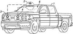
- FIG. 1illustrates a smart camera system 6 disposed in vehicle 1 .
- Smart camera system 6is disposed in vehicle 1 anywhere one skilled in the art would deem suitable for the smart camera system 6 to view and assess transportation infrastructure.
- Smart camera system 6may include a smart camera 2 , an electronic control module (ECM) 3 , a single board computer (SBC) 4 , a Global Positioning System (GPS) 5 and a transmitter (not pictured).
- Vehicle 1may also be equipped with sensors (not pictured). These sensors are either factory sensors and/or installed after vehicle 1 was purchased.
- the SBC 4may operate as a motherboard, where data may be stored and may further be configured to allow smart camera system 6 to communicate with sensors, such as but not limited to, humidity sensors, temperature sensors, proximity sensors, optical sensors, position sensors, environment sensors, ultrasonic sensor, passive infrared sensor, distance sensor, hall effect sensor, variable reluctance sensor, speed sensors, and/or the like.
- the ECM 3is an embedded system that controls one or more of the electrical systems or subsystems in a transport vehicle.
- Both SBC 4 and ECM 3may be disposed anywhere in the vehicle one skilled in the art would deem suitable.
- the data collected by smart camera system 6 and the sensorsmay be transmitted to a server 41 .
- a transmitter(not illustrated) may communicate with server 41 , discussed below, wirelessly through a computer and/or a cellular network. In examples, the transmitter may directly connect with a computer network. Data from smart camera system 6 may be transmitted in real time to server 41 .
- FIG. 2illustrates data being collected at its point of origin.
- a vehicle 1that may be equipped with smart camera system 6 and sensors may collect and record data of transportation infrastructure 12 .
- FIG. 2illustrates vehicle 1 traveling along transportation infrastructure 12 .
- Smart camera system 6 and sensorsmay utilize many different methods for collecting data. Such techniques may include, but are not limited to video, lidar, and other sensors.
- smart camera system 6may illuminate the transportation infrastructure 12 with a pulsed laser light 11 . Pulsed laser light 11 is reflected back and may be measured using a sensor. These measurements may then determine the visibility of transportation infrastructure 12 such as, but not limited to pavement markings 10 , identification signs, traffic conditions, and/or the like. This information may be transmitted in real time to server 41 where the information may be compiled and analyzed.
- the transportation infrastructure 12may then be categorized into sections based on measurements from smart camera system 6 .
- vehicle 1may be travelling within a transportation infrastructure 12 recording and collecting data. These recordings may identify at least one part of transportation infrastructure 12 as good sections 20 and as bad sections 21 .
- good sections 20may be defined as visible pavement markings and bad sections 21 may be defined as faint or obscure pavement markings.
- Thisis one example of the types of data that may be collected from transportation infrastructure 12 .
- other types of data collected pertaining to transportation infrastructure 12may include, but is not limited to, the infrastructure integrity, visibility of pavement markings 10 , signs, weather conditions, traffic conditions, estimated repair costs, daily travel, speed limit, traffic incidents. Weather conditions may further include, temperature, relative humidity, forecast and the like.
- FIG. 4illustrates that a fleet of vehicles 1 (reference to FIG. 1 ), which may be disposed within sectors 30 may generate data over a geographical area 31 , which may provide a breakdown of transportation infrastructure 12 .
- a geographical area 31the information gathered by the fleet is collected, transmitted to a remote server and/or servers 41 (refer to FIG. 5 ), compiled, analyzed, and then processed.
- the datais then displayed on a dashboard 60 , as discussed below.
- Dashboard 60may be displayed on any device 47 , discussed below, capable of accessing server 41 .
- Non-limiting examples of devices 42 which may be capable of accessing server 41are smart phones, tablets and/or traditional computers.
- FIG. 5illustrates that data from a plurality of vehicles 1 may send recorded data to HUB 40 which may communicated the recorded data to server 41 .
- Server 41may analyze and process the data which may be accessed by device 42 which may display conditions of transportation infrastructure 12 .
- Device 42may produce web based products.
- the informationmay be transmitted wirelessly through a computer network, wirelessly through a cellular network or through a direct connection with a computer network.
- the configured datais then accessible either directly at the server 41 or offsite by device 42 that communicates wirelessly with the server 41 or the data is accessible off site by device 42 that is directly connected to the server 41 through a computer network.
- the information collected by a plurality of vehicles 1 concerning a geographical regionmay be sent to a third party. This third party may then use this information as desired.
- the third partymay be a government entity.
- the government entitymay use the collected data to make road improvement and repair decisions.
- the geographical regionmay include, but is not limited to, a road, a county, a district, a state, a country, and or any combination thereof.
- FIG. 6illustrates additional information collected by smart camera system 6 that may be disclosed by web based products.
- this informationis included in the information that is collected by the vehicles 1 and transmitted to a server and/or servers 41 .
- the additional informationmay include smart camera systems 6 in vehicles 1 , conditions of transportation infrastructure 50 , transportation planning and programming traffic counts 51 , and weather 52 .
- Conditions of transportation infrastructuremay include traffic information, pavement markings, transportation infrastructure signs, and the like.
- Transportation planning and programming traffic countsinclude information about traffic such as, but not limited to, when and where traffic normally occurs.
- Weatherincludes information including, but not limited to, the dew point, the temperature, the relative humidity, and or the like.
- FIG. 7illustrates a high level view of the dashboard 60 .
- This view of dashboard 60may include information such as, but not limited to, integrity breakdown 62 , daily travel 63 , lane types 64 , and/or lane capacity 65 .
- the integrity breakdown 62may further include, but is not limited to, the percentage of low integrity roads, estimated cost of repair, and/or average road coverage.
- Daily travel 63may include information such as, but not limited to, the amount of transportation vehicles that may traverse at least a portion of transportation infrastructure.
- Lane types 64may be further broken down into categories including, but not limited to, broken line, double solid line, single solid line, and/or other. It should be noted that dashboard 60 may be configured to display integrity breakdown 62 , daily travel 63 , lane types 64 , and/or lane capacity 65 device 42 in any suitable configuration.
- FIG. 8illustrates a dashboard 60 showing location specific details in accordance with embodiments of the present disclosure.
- Specific locationmay include, but is not limited to, a specific road.
- the information displayedmay include, but is not limited to, the name of the road 70 being analyzed, the road integrity 71 , the weather conditions 52 and traffic statistics 72 .
- the road integrity 71may include information such as pavement conditions and or visibility of pavement markings.
- the weather conditions 52may include information such as relative humidity, temperature, and/or the projected forecast.
- Traffic statistics 72include information such as times and places where traffic is frequent.
- Information displayed on the dashboard 60may further comprise the average road integrity, average daily traffic, average traffic incidents, estimated repair costs, customer complaints, speed limit, and time since last repair. It should be noted that dashboard 60 may be displayed on device 42 in any suitable configuration.
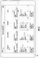
- FIG. 9illustrates a dashboard 60 showing At-a-Glance Reporting in accordance with embodiments of the present disclosure.
- Dashboard 60displays information pertaining to a district 80 broken up by counties 81 .
- Information displayed on dashboard 60may include, but is not limited to, road integrity 71 and integrity breakdown 62 .
- the road integrity 71may include information such as pavement conditions and or visibility of pavement markings.
- Integrity breakdown 62may break down the roads traveled according to their integrity ranking, such as good, moderate, bad, and/or other.
- Information displayed on dashboard 60may further comprise, but is not limited to, repair costs and repair time. It should be noted that dashboard 60 may be displayed on device 42 in any suitable configuration.
- FIG. 10illustrates a dashboard 60 showing Fleet Analytics in accordance with embodiments of the present disclosure.
- This dashboard 60may display information pertaining to fleet activity 92 over district 80 .
- This dashboard 60may display information including, but not limited to, fleet connectivity 91 , fleet distribution 90 and fleet activity 92 .
- Fleet connectivity 91may be further broken down into categories including, but not limited to, miles traveled, miles observed, and/or the percentage of the fleet that was active over district 80 .
- Fleet distribution 90shows where the fleet traveled and how often.
- Fleet activity 92shows how long the plurality of vehicles 1 were active in said geographical area 31 .
- dashboard 60may be displayed on device 42 in any suitable configuration.
- sensorsmay include, but are not limited to humidity sensors, temperature sensors, proximity sensors, optical sensors, position sensors, environment sensors, ultrasonic sensor, passive infrared sensor, distance sensor, hall effect sensor, variable reluctance sensor, speed sensors and the like.
Landscapes
- Engineering & Computer Science (AREA)
- Multimedia (AREA)
- Signal Processing (AREA)
- Physics & Mathematics (AREA)
- General Physics & Mathematics (AREA)
- Theoretical Computer Science (AREA)
- Software Systems (AREA)
- Traffic Control Systems (AREA)
Abstract
Description
Claims (14)
Priority Applications (3)
| Application Number | Priority Date | Filing Date | Title |
|---|---|---|---|
| US15/636,597US11006082B2 (en) | 2016-06-28 | 2017-06-28 | Highway infrastructure inventory and assessment device |
| US16/797,224US20200195892A1 (en) | 2016-06-28 | 2020-02-21 | Highway infrastructure inventory and assessment device |
| US17/316,195US11924584B2 (en) | 2016-06-28 | 2021-05-10 | Highway infrastructure inventory and assessment device |
Applications Claiming Priority (2)
| Application Number | Priority Date | Filing Date | Title |
|---|---|---|---|
| US201662355444P | 2016-06-28 | 2016-06-28 | |
| US15/636,597US11006082B2 (en) | 2016-06-28 | 2017-06-28 | Highway infrastructure inventory and assessment device |
Related Child Applications (2)
| Application Number | Title | Priority Date | Filing Date |
|---|---|---|---|
| US16/797,224ContinuationUS20200195892A1 (en) | 2016-06-28 | 2020-02-21 | Highway infrastructure inventory and assessment device |
| US17/316,195ContinuationUS11924584B2 (en) | 2016-06-28 | 2021-05-10 | Highway infrastructure inventory and assessment device |
Publications (2)
| Publication Number | Publication Date |
|---|---|
| US20180027215A1 US20180027215A1 (en) | 2018-01-25 |
| US11006082B2true US11006082B2 (en) | 2021-05-11 |
Family
ID=60989669
Family Applications (3)
| Application Number | Title | Priority Date | Filing Date |
|---|---|---|---|
| US15/636,597Expired - Fee RelatedUS11006082B2 (en) | 2016-06-28 | 2017-06-28 | Highway infrastructure inventory and assessment device |
| US16/797,224AbandonedUS20200195892A1 (en) | 2016-06-28 | 2020-02-21 | Highway infrastructure inventory and assessment device |
| US17/316,195ActiveUS11924584B2 (en) | 2016-06-28 | 2021-05-10 | Highway infrastructure inventory and assessment device |
Family Applications After (2)
| Application Number | Title | Priority Date | Filing Date |
|---|---|---|---|
| US16/797,224AbandonedUS20200195892A1 (en) | 2016-06-28 | 2020-02-21 | Highway infrastructure inventory and assessment device |
| US17/316,195ActiveUS11924584B2 (en) | 2016-06-28 | 2021-05-10 | Highway infrastructure inventory and assessment device |
Country Status (1)
| Country | Link |
|---|---|
| US (3) | US11006082B2 (en) |
Cited By (2)
| Publication number | Priority date | Publication date | Assignee | Title |
|---|---|---|---|---|
| US11924584B2 (en) | 2016-06-28 | 2024-03-05 | Ennis-Flint, Inc. | Highway infrastructure inventory and assessment device |
| US12177740B2 (en) | 2021-09-28 | 2024-12-24 | Univrses Ab | Managing mobile data gathering agents |
Families Citing this family (4)
| Publication number | Priority date | Publication date | Assignee | Title |
|---|---|---|---|---|
| WO2020069517A2 (en) | 2018-09-30 | 2020-04-02 | Strong Force Intellectual Capital, Llc | Intelligent transportation systems |
| US11631151B2 (en) | 2018-09-30 | 2023-04-18 | Strong Force Tp Portfolio 2022, Llc | Intelligent transportation systems |
| US12067791B2 (en)* | 2022-06-23 | 2024-08-20 | Inuitive Ltd. | Method and system for roads' maintenance |
| US20250166096A1 (en)* | 2023-11-21 | 2025-05-22 | Civil Lite, LLC | Infrastructure Management Systems and Methods |
Citations (16)
| Publication number | Priority date | Publication date | Assignee | Title |
|---|---|---|---|---|
| US20070038338A1 (en)* | 2005-08-15 | 2007-02-15 | Larschan Bradley R | Driver activity and vehicle operation logging and reporting |
| US20070041614A1 (en)* | 2005-08-18 | 2007-02-22 | Fujitsu Limited | Road marking recognition apparatus and method |
| US20070132608A1 (en)* | 2005-12-08 | 2007-06-14 | Votaw Sean R | Emergency vehicle warning system |
| US20080082347A1 (en)* | 2006-09-29 | 2008-04-03 | Oscar Ernesto Villalobos | Haul road maintenance management system |
| US20090021385A1 (en)* | 2007-06-15 | 2009-01-22 | Tesla Motors, Inc. | Electric Vehicle Communication Interface |
| US20100001883A1 (en)* | 2005-07-19 | 2010-01-07 | Winfried Koenig | Display Device |
| US20110094840A1 (en)* | 2009-10-26 | 2011-04-28 | Masami Sakita | Electric highway system |
| US20120194679A1 (en)* | 2011-01-31 | 2012-08-02 | Nehowig Kelly R | Multi-mode vehicle computing device supporting in-cab and stand-alone operation |
| US20130316737A1 (en)* | 2009-05-08 | 2013-11-28 | Obdedge, Llc | Systems, Methods, and Devices for Policy-Based Control and Monitoring of Use of Mobile Devices by Vehicle Operators |
| US20140334689A1 (en)* | 2013-05-07 | 2014-11-13 | International Business Machines Corporation | Infrastructure assessment via imaging sources |
| US20160048810A1 (en)* | 2014-03-18 | 2016-02-18 | Fujitsu Limited | Extracting method, recommending method, information processing apparatus and method for decision support on road repair method |
| US20160093216A1 (en)* | 2014-09-29 | 2016-03-31 | Avis Budget Car Rental, LLC | Telematics System, Methods and Apparatus for Two-way Data Communication Between Vehicles in a Fleet and a Fleet Management System |
| US20160117923A1 (en)* | 2014-10-27 | 2016-04-28 | Here Global B.V. | Negative Image for Sign Placement Detection |
| US20160247335A1 (en)* | 2013-04-11 | 2016-08-25 | The University Of Tulsa | Wheeled Vehicle Event Data Recorder Forensic Recovery and Preservation System |
| US20170213084A1 (en)* | 2016-01-22 | 2017-07-27 | International Business Machines Corporation | Pavement marking determination |
| US20170351263A1 (en)* | 2016-06-02 | 2017-12-07 | Delphi Technologies, Inc. | Roadway-Infrastructure-Maintenance System Using Automated Vehicles |
Family Cites Families (2)
| Publication number | Priority date | Publication date | Assignee | Title |
|---|---|---|---|---|
| KR100758705B1 (en)* | 2007-02-01 | 2007-09-21 | 위성동 | Pavement condition automatic survey device |
| US11006082B2 (en) | 2016-06-28 | 2021-05-11 | Ennis-Flint, Inc. | Highway infrastructure inventory and assessment device |
- 2017
- 2017-06-28USUS15/636,597patent/US11006082B2/ennot_activeExpired - Fee Related
- 2020
- 2020-02-21USUS16/797,224patent/US20200195892A1/ennot_activeAbandoned
- 2021
- 2021-05-10USUS17/316,195patent/US11924584B2/enactiveActive
Patent Citations (16)
| Publication number | Priority date | Publication date | Assignee | Title |
|---|---|---|---|---|
| US20100001883A1 (en)* | 2005-07-19 | 2010-01-07 | Winfried Koenig | Display Device |
| US20070038338A1 (en)* | 2005-08-15 | 2007-02-15 | Larschan Bradley R | Driver activity and vehicle operation logging and reporting |
| US20070041614A1 (en)* | 2005-08-18 | 2007-02-22 | Fujitsu Limited | Road marking recognition apparatus and method |
| US20070132608A1 (en)* | 2005-12-08 | 2007-06-14 | Votaw Sean R | Emergency vehicle warning system |
| US20080082347A1 (en)* | 2006-09-29 | 2008-04-03 | Oscar Ernesto Villalobos | Haul road maintenance management system |
| US20090021385A1 (en)* | 2007-06-15 | 2009-01-22 | Tesla Motors, Inc. | Electric Vehicle Communication Interface |
| US20130316737A1 (en)* | 2009-05-08 | 2013-11-28 | Obdedge, Llc | Systems, Methods, and Devices for Policy-Based Control and Monitoring of Use of Mobile Devices by Vehicle Operators |
| US20110094840A1 (en)* | 2009-10-26 | 2011-04-28 | Masami Sakita | Electric highway system |
| US20120194679A1 (en)* | 2011-01-31 | 2012-08-02 | Nehowig Kelly R | Multi-mode vehicle computing device supporting in-cab and stand-alone operation |
| US20160247335A1 (en)* | 2013-04-11 | 2016-08-25 | The University Of Tulsa | Wheeled Vehicle Event Data Recorder Forensic Recovery and Preservation System |
| US20140334689A1 (en)* | 2013-05-07 | 2014-11-13 | International Business Machines Corporation | Infrastructure assessment via imaging sources |
| US20160048810A1 (en)* | 2014-03-18 | 2016-02-18 | Fujitsu Limited | Extracting method, recommending method, information processing apparatus and method for decision support on road repair method |
| US20160093216A1 (en)* | 2014-09-29 | 2016-03-31 | Avis Budget Car Rental, LLC | Telematics System, Methods and Apparatus for Two-way Data Communication Between Vehicles in a Fleet and a Fleet Management System |
| US20160117923A1 (en)* | 2014-10-27 | 2016-04-28 | Here Global B.V. | Negative Image for Sign Placement Detection |
| US20170213084A1 (en)* | 2016-01-22 | 2017-07-27 | International Business Machines Corporation | Pavement marking determination |
| US20170351263A1 (en)* | 2016-06-02 | 2017-12-07 | Delphi Technologies, Inc. | Roadway-Infrastructure-Maintenance System Using Automated Vehicles |
Cited By (2)
| Publication number | Priority date | Publication date | Assignee | Title |
|---|---|---|---|---|
| US11924584B2 (en) | 2016-06-28 | 2024-03-05 | Ennis-Flint, Inc. | Highway infrastructure inventory and assessment device |
| US12177740B2 (en) | 2021-09-28 | 2024-12-24 | Univrses Ab | Managing mobile data gathering agents |
Also Published As
| Publication number | Publication date |
|---|---|
| US11924584B2 (en) | 2024-03-05 |
| US20200195892A1 (en) | 2020-06-18 |
| US20180027215A1 (en) | 2018-01-25 |
| US20210409651A1 (en) | 2021-12-30 |
Similar Documents
| Publication | Publication Date | Title |
|---|---|---|
| US11924584B2 (en) | Highway infrastructure inventory and assessment device | |
| US10989556B1 (en) | Traffic risk a avoidance for a route selection system | |
| US10933881B1 (en) | System for adjusting autonomous vehicle driving behavior to mimic that of neighboring/surrounding vehicles | |
| US11361556B2 (en) | Deterioration diagnosis device, deterioration diagnosis system, deterioration diagnosis method, and storage medium for storing program | |
| US11157973B2 (en) | System and method for estimation of vehicle accident damage and repair | |
| US12049218B2 (en) | Evaluating the safety performance of vehicles | |
| US11727595B2 (en) | Assessing visibility of a target object with autonomous vehicle fleet | |
| US20210295443A1 (en) | Automobile risk assessment using the average velocity of relevant vehicles | |
| US20210270620A1 (en) | Traffic Risk Notification System | |
| WO2015075736A2 (en) | A method and system for remote data processing and control | |
| Bock et al. | Spatio-temporal road coverage of probe vehicles: a case study on crowd-sensing of parking availability with taxis | |
| US10109191B2 (en) | Method of quickly detecting road distress | |
| Samie et al. | Potential applications of connected vehicles in pavement condition evaluation: A brief review | |
| KR20220138894A (en) | Prediction and recognition method of road marking information and road maintenance method | |
| JP5667907B2 (en) | Information provision system | |
| Brunauer et al. | Supporting road maintenance with in-vehicle data: Results from a field trial on road surface condition monitoring | |
| Grimm et al. | NORA: Towards large-scale vehicular analytics for driving environment monitoring/assessment | |
| Hammit et al. | Connected vehicle weather data for operation of rural variable speed limit corridors | |
| EP4456033A1 (en) | Gathering and distributing metadata of a surrounding of a vehicle | |
| Li et al. | Extraction of Vehicle CAN Bus Data for Roadway Condition Monitoring | |
| Hipp et al. | Vehicle Fleet Data for Cost Efficient Real-Time Road Surface Assessment | |
| Nlenanya et al. | Integration of Connected Vehicle and RWIS Technologies | |
| Alden et al. | Roadside Truck Placard Readers for Advanced Notice and Response at Safety-Critical Facilities: Phase 2 | |
| JP2024147338A (en) | Data Processing Unit | |
| US20190137632A1 (en) | Real-time automotive driver behavior |
Legal Events
| Date | Code | Title | Description |
|---|---|---|---|
| AS | Assignment | Owner name:THE TEXAS A&M UNIVERSITY SYSTEM, TEXAS Free format text:ASSIGNMENT OF ASSIGNORS INTEREST;ASSIGNOR:CARLSON, PAUL J.;REEL/FRAME:047638/0744 Effective date:20170914 | |
| STPP | Information on status: patent application and granting procedure in general | Free format text:FINAL REJECTION MAILED | |
| STCV | Information on status: appeal procedure | Free format text:NOTICE OF APPEAL FILED | |
| STPP | Information on status: patent application and granting procedure in general | Free format text:DOCKETED NEW CASE - READY FOR EXAMINATION | |
| STPP | Information on status: patent application and granting procedure in general | Free format text:NON FINAL ACTION MAILED | |
| AS | Assignment | Owner name:CARLSON, PAUL J., NORTH CAROLINA Free format text:ASSIGNMENT OF ASSIGNORS INTEREST;ASSIGNOR:THE TEXAS A&M UNIVERSITY SYSTEM;REEL/FRAME:054129/0604 Effective date:20200225 | |
| STPP | Information on status: patent application and granting procedure in general | Free format text:NOTICE OF ALLOWANCE MAILED -- APPLICATION RECEIVED IN OFFICE OF PUBLICATIONS | |
| AS | Assignment | Owner name:ENNIS-FLINT, INC., NORTH CAROLINA Free format text:ASSIGNMENT OF ASSIGNORS INTEREST;ASSIGNOR:CARLSON, PAUL J.;REEL/FRAME:055697/0487 Effective date:20210322 | |
| FEPP | Fee payment procedure | Free format text:ENTITY STATUS SET TO UNDISCOUNTED (ORIGINAL EVENT CODE: BIG.); ENTITY STATUS OF PATENT OWNER: LARGE ENTITY | |
| STPP | Information on status: patent application and granting procedure in general | Free format text:PUBLICATIONS -- ISSUE FEE PAYMENT VERIFIED | |
| STCF | Information on status: patent grant | Free format text:PATENTED CASE | |
| FEPP | Fee payment procedure | Free format text:MAINTENANCE FEE REMINDER MAILED (ORIGINAL EVENT CODE: REM.); ENTITY STATUS OF PATENT OWNER: LARGE ENTITY | |
| LAPS | Lapse for failure to pay maintenance fees | Free format text:PATENT EXPIRED FOR FAILURE TO PAY MAINTENANCE FEES (ORIGINAL EVENT CODE: EXP.); ENTITY STATUS OF PATENT OWNER: LARGE ENTITY | |
| STCH | Information on status: patent discontinuation | Free format text:PATENT EXPIRED DUE TO NONPAYMENT OF MAINTENANCE FEES UNDER 37 CFR 1.362 | |
| FP | Lapsed due to failure to pay maintenance fee | Effective date:20250511 |