US11003807B2 - Techniques for generating materials to satisfy design criteria - Google Patents
Techniques for generating materials to satisfy design criteriaDownload PDFInfo
- Publication number
- US11003807B2 US11003807B2US14/951,366US201514951366AUS11003807B2US 11003807 B2US11003807 B2US 11003807B2US 201514951366 AUS201514951366 AUS 201514951366AUS 11003807 B2US11003807 B2US 11003807B2
- Authority
- US
- United States
- Prior art keywords
- design
- custom
- candidate
- geometry
- designs
- Prior art date
- Legal status (The legal status is an assumption and is not a legal conclusion. Google has not performed a legal analysis and makes no representation as to the accuracy of the status listed.)
- Active, expires
Links
Images


Classifications
- G—PHYSICS
- G05—CONTROLLING; REGULATING
- G05B—CONTROL OR REGULATING SYSTEMS IN GENERAL; FUNCTIONAL ELEMENTS OF SUCH SYSTEMS; MONITORING OR TESTING ARRANGEMENTS FOR SUCH SYSTEMS OR ELEMENTS
- G05B19/00—Programme-control systems
- G05B19/02—Programme-control systems electric
- G05B19/18—Numerical control [NC], i.e. automatically operating machines, in particular machine tools, e.g. in a manufacturing environment, so as to execute positioning, movement or co-ordinated operations by means of programme data in numerical form
- G05B19/4097—Numerical control [NC], i.e. automatically operating machines, in particular machine tools, e.g. in a manufacturing environment, so as to execute positioning, movement or co-ordinated operations by means of programme data in numerical form characterised by using design data to control NC machines, e.g. CAD/CAM
- G—PHYSICS
- G06—COMPUTING OR CALCULATING; COUNTING
- G06F—ELECTRIC DIGITAL DATA PROCESSING
- G06F16/00—Information retrieval; Database structures therefor; File system structures therefor
- G06F16/40—Information retrieval; Database structures therefor; File system structures therefor of multimedia data, e.g. slideshows comprising image and additional audio data
- G06F16/44—Browsing; Visualisation therefor
- G06F16/444—Spatial browsing, e.g. 2D maps, 3D or virtual spaces
- G—PHYSICS
- G06—COMPUTING OR CALCULATING; COUNTING
- G06F—ELECTRIC DIGITAL DATA PROCESSING
- G06F3/00—Input arrangements for transferring data to be processed into a form capable of being handled by the computer; Output arrangements for transferring data from processing unit to output unit, e.g. interface arrangements
- G06F3/01—Input arrangements or combined input and output arrangements for interaction between user and computer
- G06F3/048—Interaction techniques based on graphical user interfaces [GUI]
- G06F3/0481—Interaction techniques based on graphical user interfaces [GUI] based on specific properties of the displayed interaction object or a metaphor-based environment, e.g. interaction with desktop elements like windows or icons, or assisted by a cursor's changing behaviour or appearance
- G—PHYSICS
- G06—COMPUTING OR CALCULATING; COUNTING
- G06F—ELECTRIC DIGITAL DATA PROCESSING
- G06F3/00—Input arrangements for transferring data to be processed into a form capable of being handled by the computer; Output arrangements for transferring data from processing unit to output unit, e.g. interface arrangements
- G06F3/01—Input arrangements or combined input and output arrangements for interaction between user and computer
- G06F3/048—Interaction techniques based on graphical user interfaces [GUI]
- G06F3/0484—Interaction techniques based on graphical user interfaces [GUI] for the control of specific functions or operations, e.g. selecting or manipulating an object, an image or a displayed text element, setting a parameter value or selecting a range
- G06F3/04847—Interaction techniques to control parameter settings, e.g. interaction with sliders or dials
- G—PHYSICS
- G06—COMPUTING OR CALCULATING; COUNTING
- G06F—ELECTRIC DIGITAL DATA PROCESSING
- G06F30/00—Computer-aided design [CAD]
- G—PHYSICS
- G06—COMPUTING OR CALCULATING; COUNTING
- G06F—ELECTRIC DIGITAL DATA PROCESSING
- G06F30/00—Computer-aided design [CAD]
- G06F30/20—Design optimisation, verification or simulation
- G—PHYSICS
- G06—COMPUTING OR CALCULATING; COUNTING
- G06T—IMAGE DATA PROCESSING OR GENERATION, IN GENERAL
- G06T15/00—3D [Three Dimensional] image rendering
- G06T15/10—Geometric effects
- G—PHYSICS
- G06—COMPUTING OR CALCULATING; COUNTING
- G06T—IMAGE DATA PROCESSING OR GENERATION, IN GENERAL
- G06T19/00—Manipulating 3D models or images for computer graphics
- G06T19/20—Editing of 3D images, e.g. changing shapes or colours, aligning objects or positioning parts
- G—PHYSICS
- G05—CONTROLLING; REGULATING
- G05B—CONTROL OR REGULATING SYSTEMS IN GENERAL; FUNCTIONAL ELEMENTS OF SUCH SYSTEMS; MONITORING OR TESTING ARRANGEMENTS FOR SUCH SYSTEMS OR ELEMENTS
- G05B2219/00—Program-control systems
- G05B2219/30—Nc systems
- G05B2219/32—Operator till task planning
- G05B2219/32089—Action and material and technology combined to manufacture product
- G—PHYSICS
- G05—CONTROLLING; REGULATING
- G05B—CONTROL OR REGULATING SYSTEMS IN GENERAL; FUNCTIONAL ELEMENTS OF SUCH SYSTEMS; MONITORING OR TESTING ARRANGEMENTS FOR SUCH SYSTEMS OR ELEMENTS
- G05B2219/00—Program-control systems
- G05B2219/30—Nc systems
- G05B2219/35—Nc in input of data, input till input file format
- G05B2219/35012—Cad cam
- G—PHYSICS
- G05—CONTROLLING; REGULATING
- G05B—CONTROL OR REGULATING SYSTEMS IN GENERAL; FUNCTIONAL ELEMENTS OF SUCH SYSTEMS; MONITORING OR TESTING ARRANGEMENTS FOR SUCH SYSTEMS OR ELEMENTS
- G05B2219/00—Program-control systems
- G05B2219/30—Nc systems
- G05B2219/35—Nc in input of data, input till input file format
- G05B2219/35021—Identify object characteristics, elasticity, density, hardness and select material
- G—PHYSICS
- G05—CONTROLLING; REGULATING
- G05B—CONTROL OR REGULATING SYSTEMS IN GENERAL; FUNCTIONAL ELEMENTS OF SUCH SYSTEMS; MONITORING OR TESTING ARRANGEMENTS FOR SUCH SYSTEMS OR ELEMENTS
- G05B2219/00—Program-control systems
- G05B2219/30—Nc systems
- G05B2219/49—Nc machine tool, till multiple
- G05B2219/49301—Identify material to be used, select between several
- Y—GENERAL TAGGING OF NEW TECHNOLOGICAL DEVELOPMENTS; GENERAL TAGGING OF CROSS-SECTIONAL TECHNOLOGIES SPANNING OVER SEVERAL SECTIONS OF THE IPC; TECHNICAL SUBJECTS COVERED BY FORMER USPC CROSS-REFERENCE ART COLLECTIONS [XRACs] AND DIGESTS
- Y02—TECHNOLOGIES OR APPLICATIONS FOR MITIGATION OR ADAPTATION AGAINST CLIMATE CHANGE
- Y02P—CLIMATE CHANGE MITIGATION TECHNOLOGIES IN THE PRODUCTION OR PROCESSING OF GOODS
- Y02P80/00—Climate change mitigation technologies for sector-wide applications
- Y02P80/40—Minimising material used in manufacturing processes
Definitions
- Embodiments of the present inventionrelate generally to engineering design and, more specifically, to techniques for generating materials to satisfy design criteria.
- an engineeruses a computer-aided design (CAD) tool to design and draft physical parts to meet specific design criteria. The engineer then selects a material from which to fabricate the part and initiates the process of manufacturing the part using the selected material.
- CADcomputer-aided design
- Each material available for manufacturingmay have different material attributes.
- that parthas particular static and dynamic attributes that derive from both the geometry of the part and the attributes of the material of manufacture.
- a design having a particular geometrycan be or must be manufactured from a specific material in order to generate a physical part that meets the design criteria.
- the particular geometryis such that there are no specific materials available having the physical properties required to generate a physical part that can meet the design criteria.
- a certain designmay have a truss geometry that, based on design criteria, must support a minimum load without exceeding a maximum weight.
- Various embodiments of the present inventionsets forth a non-transitory computer-readable medium including instructions that, when executed by a processor, cause the processor to generate a material, by performing the steps of generating a material design, based on a design problem described in a problem specification, that includes instructions for fabricating a custom material that satisfies at least one design criterion associated with the design problem, and causing a manufacturing machine to fabricate the custom material based on the material design.
- At least one advantage of this approachis that engineers no longer need to rely solely on pre-existing materials when creating designs to solve specific design problems.
- FIG. 1illustrates a system configured to implement one or more aspects of the present invention.
- FIG. 2is a more detailed illustration of the design application of FIG. 1 , according to various embodiments of the present invention
- FIG. 3Ais an exemplary plot illustrating a custom material having attributes beyond those associated with existing materials, according to various embodiments of the present invention
- FIG. 3Bis an exemplary custom material that includes amorphous substructures having distinct material attributes, according to various embodiments of the present invention.
- FIG. 4illustrates a design space where design problem geometry can be generated, according to various embodiments of the present invention
- FIG. 5illustrates different design criteria applied within the design space of FIG. 4 , according to various embodiments of the present invention
- FIG. 6illustrates a material design created using a lattice approach, according to various embodiments of the present invention
- FIG. 7illustrates a material design created using a composite skin approach, according to various embodiments of the present invention.
- FIG. 8illustrates a material design created using a unit cell approach, according to various embodiments of the present invention.
- FIG. 9is a flow diagram of method steps for creating a custom material to meet design criteria associated with a design problem, according to various embodiments of the present invention.
- FIG. 1illustrates a system 100 configured to implement one or more aspects of the present invention.
- system 100includes a client 110 coupled via a network 130 to a server 150 .
- Client 110may be any technically feasible variety of client computing device, including a desktop computer, laptop computer, mobile device, and so forth.
- Network 150may be any technically feasible set of interconnected communication links, including a local area network (LAN), wide area network (WAN), the World Wide Web, or the Internet, among others.
- Server 150may be any technically feasible type of server computing device, including a remote virtualized instance of a computing device, one or more physical cloud-based computing devices, a mixture of the two, a portion of a datacenter, and so forth.
- Client 110includes processor 112 , input/output (I/O) devices 114 , and memory 116 , coupled together.
- Processor 112may be any technically feasible form of processing device configured process data and execute program code.
- Processor 112could be, for example, a central processing unit (CPU), a graphics processing unit (GPU), an application-specific integrated circuit (ASIC), a field-programmable gate array (FPGA), and so forth.
- I/O devices 114may include devices configured to receive input, including, for example, a keyboard, a mouse, and so forth.
- I/O devices 114may also include devices configured to provide output, including, for example, a display device, a speaker, and so forth.
- I/O devices 114may further include devices configured to both receive and provide input and output, respectively, including, for example, a touchscreen, a universal serial bus (USB) port, and so forth.
- USBuniversal serial bus
- Memory 116may be any technically feasible storage medium configured to store data and software applications.
- Memory 116could be, for example, a hard disk, a random access memory (RAM) module, a read-only memory (ROM), and so forth.
- RAMrandom access memory
- ROMread-only memory
- Memory 116includes client-side design application 120 - 0 and client-side database 122 - 0 .
- Client-side design application 120 - 0is a software application that, when executed by processor 112 , causes processor 112 to design a custom material having specific material attributes. In doing so, client-side design application 120 - 0 may access client-side database 122 - 0 .
- Client-side design application 122 - 0may also interoperate with a corresponding design application that resides within server 150 and access a database that also resides on server 150 , as described in greater detail below.
- Server 150includes processor 152 , I/O devices 154 , and memory 156 , coupled together.
- Processor 152may be any technically feasible form of processing device configured to process data and execute program code, including a CPU, a GPU, an ASIC, an FPGA, and so forth.
- I/O devices 114may include devices configured to receive input, devices configured to provide output, and devices configured to both receive and provide input and output, respectively.
- Memory 156may be any technically feasible storage medium configured to store data and software applications, including a hard disk, a RAM module, a ROM, and so forth.
- Memory 156includes server-side design application 120 - 1 and server-side database 122 - 1 .
- Server-side design application 120 - 1is a software application that, when executed by processor 156 , causes processor 152 to design a custom material having specific material attributes. In doing so, server-side design application 120 - 1 may access server-side database 122 - 1 .
- Server-side design application 122 - 1may also interoperate with client-side design application 120 - 0 and access client-side database 122 - 0 .
- client-side design application 120 - 0 and server-side design application 120 - 1cooperate to implement any and all of the inventive functionality described herein. In doing so, either one or both of client-side design application 120 - 0 and server-side design application 120 - 1 may access either one or both of client-side database 122 - 0 and server-side database 122 - 1 .
- client-side design application 120 - 0 and server-side design application 120 - 1represent different portions of single distributed software entity.
- client-side design application 122 - 0 and server-side design application 122 - 1will be collectively referred to herein as design application 120 .
- client-side database 122 - 0 and server-side database 122 - 1represent different portions of a single distributed storage entity. Therefore, for simplicity, client-side database 122 - 0 and server-side database 122 - 1 will be collectively referred to herein as database 122 .
- design application 120is configured to interact with an end-user in order to synthesize a problem specification for a design problem. Then, design application designs a custom material that can be used to create engineering designs that solve the design problem.
- An advantage of this approachis that a spectrum of design options need not be limited by the absence of real-world materials that have particular attributes, because design application 120 is capable of simply creating new materials having those particular attributes, as also explained in conjunction with FIG. 3A-3B .
- FIG. 2is a more detailed illustration of the design application of FIG. 1 , according to various embodiments of the present invention.
- design application 120includes without limitation, a setup engine 200 , a problem specification 202 , design approaches 204 , a materials engine 206 , materials data 208 , material designs 210 , a simulation engine 212 , a graphical user interface (GUI) engine 216 , and a GUI 218 .
- Design application 120is coupled to a manufacturing machine 220 that is configured to generate custom materials 222 .
- Setup engine 202is configured to generate problem specification 202 and design approaches 204 .
- Materials engine 204is configured to process design approaches 204 and materials data 208 to generate material designs 210 .
- Simulation engine 212is configured to simulate virtual instances of materials associated with material designs 210 .
- GUI engine 216is configured to generate GUI 218 .
- An end-usermay interact with setup engine 200 , materials engine 204 , simulation engine 212 , and GUI engine 216 via GUI 214 .
- Setup engine 200provides various tools that allow the end-user to define a design problem to be solved within a design space associated with a simulated three-dimensional (3D) environment.
- the end-usermay interact with setup engine 200 , via GUI 216 , to define design problem geometry, design objectives, design constraints, boundary conditions, and other data associated with the design problem.
- Setup engine 200synthesizes this data in problem specification 202 . An example of this process is described in greater detail below in conjunction with FIGS. 4-5 .
- Problem specification 202is a data structure that embodies all of the design problem information received via interactions with the end-user.
- problem specification 202could reflect a 3D environment that includes specific locations where certain forces are to be supported, within precise volumetric constraints, under particular weight limitations.
- Setup engine 200is configured to analyze problem specification 202 and to then identify, within database 122 , one or more design approaches 204 applicable to the design problem outlined in problem specification 202 .
- a given design approach 204represents a procedure for creating a design for a material having specific material attributes and/or combinations of attributes.
- a design approach 204could include a lattice optimization algorithm that creates lattices that could have a range of physical attributes.
- Materials engine 206is configured to execute each design approach 204 to generate material designs 210 .
- Each material design 210represents instructions for generating a custom material.
- materials engine 206may generate a wide range of possible design candidates, and then simulate each such candidate via simulation engine 212 .
- Simulation engine 212relies on materials data 208 to perform simulations.
- Materials data 208defines various attributes of existing materials, including density, thermal conductivity, strength, hardness, Young's modulus, Poisson Ratio, ductility, and so forth.
- a material design 210may indicate that two or more existing materials should be combined in a particular manner.
- Simulation engine 212may predict the attributes of such a material based, at least in part, on materials data 208 .
- materials engine 206When a given candidate design has material attributes that meet the design criteria, materials engine 206 includes that design in material designs 210 . In one embodiment, materials engine 206 creates a wide range of candidate geometry composed of simulated materials derived from candidate material designs, and then simulates that candidate geometry via simulation engine 212 to determine whether the design criteria is satisfied. Then, materials engine 206 may identify the candidate geometry and candidate material design as solving the design problem.
- design application 120may then transmit those designs to manufacturing machine 220 .
- Manufacturing machine 220could be a stereolithography machine, a fused deposition modeling machine, a selective laser sintering machine, an electronic beam melting machine, a laminated object manufacturing machine, a metal alloy fabrication machine, or any other type of 3D printing machine.
- Manufacturing machine 220is configured to execute commands included in material designs 210 to generate custom materials 222 .
- Each custom material 22has a particular combination of material attributes designed to effectively solve the design problem associated with design specification 202 .
- design application 120may create materials having fundamentally different combinations of material attributes compared to any pre-existing materials, as described in greater detail below in conjunction with FIG. 3A .
- FIG. 3Ais an exemplary plot illustrating a custom material having attributes beyond those associated with known materials, according to various embodiments of the present invention.
- plot 300includes an X-axis 302 corresponding to density and a Y-axis 304 corresponding to strength.
- Plot 300shows various regions of existing materials 310 and a region of custom materials 222 .
- Each material within a given region 310has a particular density value and a particular strength value.
- each region 310represents a range of density and strength attributes associated with a different type of real-world material. For example, metals are shown to be both dense and strong, occupying higher ranges of density and strength. Conversely, woods are shown to be comparatively light and weak, occupying lower ranges of density and strength.
- Custom materials 222have attributes that fall outside of regions 310 , and thus have unique combinations of density and strength, in the example shown.
- an existing materialsuch as a metal or a wood
- an existing materialmay not be suitable for use in manufacturing a particular design.
- an existing materialmay not confer sufficient strength for a given density of material.
- the particular material attributes needed to fabricate a design that meets the design criteriacan be determined based on the geometry of that design. For example, suppose problem specification 202 indicated that a particular volume of material was needed to support a specific load, and could not exceed a given amount of deformation. Based on well-known physical laws, these design objectives and design constraints provide sufficient information to identify the particular material attributes needed in a material. In the above example, Hooke's law of springs would allow the stiffness of the needed material to be computed based on the applied load and maximum deformation.
- Materials engine 206is configured to analyze problem specification 202 , in the manner described above, in order to determine the specific combination of material attributes needed for a material that could potentially yield a feasible design. Those material attributes could correspond, for example, to the unique combination of strength and density associated with custom materials 222 shown in FIG. 3A , although persons skilled in the art will understand that custom materials 222 may have any combination of material attributes. In performing this technique, materials engine 206 may generate a simulated material having the specific combination of material attributes needed. Then, by selecting and executing a design approach 204 , materials engine 206 may generate a material design 210 having the needed attributes of that simulated material.
- FIG. 3Bis an exemplary custom material that includes amorphous substructures having distinct material attributes, according to various embodiments of the present invention.
- custom material 222includes substructures 320 , 330 , 340 , and 350 .
- Each substructure shownmay be formed to have a particular combination of material attributes, thereby imbuing custom material 222 with a unique set of material attributes.
- each substructure shownmay be formed with any material attribute having a gradient in a given direction. For example, substructure 340 could have a density gradient from left to right.
- Each substructuremay be any technically feasible type of material and may be bonded or otherwise coupled to other substructures via any technically feasible approach.
- Materials engine 206is configured to generate custom material 222 by iteratively depositing different materials in a simulated environment and then testing the resultant material design to determine whether a physical instance of that material potentially has a target set of attributes. Then, when a suitable combination of materials is determined, materials engine 206 causes manufacturing machine 220 to generate custom material 222 based on the associated material design.
- Materials engine 206is configured to implement a wide variety of techniques for creating custom material 222 based on material designs, as described in greater detail below in conjunction with FIGS. 4-8 .
- FIGS. 4-5illustrated below, illustrate how an exemplary design problem is defined in problem specification 202
- FIGS. 6-8illustrate exemplary execution of design approaches 204 for generating material designs 210 .
- FIG. 4illustrates a design space where design problem geometry can be generated, according to various embodiments of the present invention.
- a design space 400includes planes 410 and 420 .
- GUI engine 216may render design space 400 within GUI 218 .
- Planes 410 and 420generally represent geometry associated with a design problem.
- Setup engine 200generates planes 410 and 420 within design space 400 based on interactions with the end-user.
- Setup engine 200then updates problem specification 202 to reflect design space 400 .
- Setup engine 200may also add various design criteria to design space 400 , as described below in conjunction with FIG. 5 .
- FIG. 5illustrates different design criteria applied within the design space of FIG. 4 , according to various embodiments of the present invention.
- design space 400includes a force 500 applied to plane 410 , a torque 510 applied to plane 420 , a distance constraint 520 between planes 410 and 420 , and an angle constraint 530 on plane 420 .
- Design space 400also includes a design objective (not shown) indicating that a feasible design will couple boundaries 410 and 420 to one another.
- Force 500represents a boundary condition to be balanced by a feasible design.
- Torque 510also represents a boundary condition to be balanced by a feasible deign.
- Distance constraint 520indicates that, when loaded by force 500 , plane 410 should not approach within distance d of plane 420 , when loaded by torque 510 .
- Angle constraint 530indicates that plane 420 should not rotate greater than angle a when loaded with torque 510 .
- Setup engine 200synthesizes this information within problem specification 202 . Then, based on that specification, setup engine 200 identifies design approaches 204 that can be used to generate a custom material between planes 410 and 420 having specific material properties that allow the various design criteria discussed above to be met.
- FIGS. 6-8illustrate exemplary custom materials created using various design approaches.
- FIG. 6illustrates a material design created using a lattice approach, according to various embodiments of the present invention.
- a material design 600includes materials 610 and 620 .
- materials 610 and 620may be any material having any technically feasible combination of material attributes.
- Material 610generally assumes geometry associated with a 3D lattice, while material 620 fills gaps between lattice members formed by material 610 .
- Materials engine 206generates material design 600 based on a design approach 204 that specifies procedures for creating lattices. That approach could include, for example, a lattice optimization algorithm, among other techniques for creating topology.
- materials engine 206When creating material design 600 , materials engine 206 generates individual lattice members having specific thicknesses, densities, and other geometric or material attributes, in order to cause material design 600 as a whole to meet the design criteria set forth in problem specification 202 . In doing so, materials engine 206 may execute a multi-objective solver, parametric variation algorithm, or other optimization algorithm to optimize the geometry, placement, and composition of each portion of the lattice.
- FIG. 7illustrates another exemplary approach to generating a custom material.
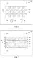
- FIG. 7illustrates a material design created using a composite skin approach, according to various embodiments of the present invention.
- a material design 700includes various layers 710 , 720 , 730 , 740 , and 750 deposited between planes 410 and 420 . Each layer is associated with a specific thickness. Layer 710 has a thickness t 1 , layer 720 has a thickness t 2 , layer 730 has a thickness t 3 , layer 740 has a thickness t 4 , and layer 750 has a thickness t 5 .
- Materials engine 206generates material design 700 based on a design approach 204 that specifies procedures for arranging different layers of materials.
- materials engine 206may execute a parameter variation algorithm to vary the number, thickness, and placement of each layer, as well as the specific material used for each layer. By varying these parameters in this manner, materials engine 206 may cause material design 700 as a whole to meet the design criteria set forth in problem specification 202 . In doing so, materials engine 206 may execute a multi-objective solver or other optimization algorithm to optimize the geometry, placement, and composition of each layer.
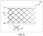
- FIG. 8illustrates another exemplary approach to generating a custom material.
- FIG. 8illustrates a material design created using a unit cell approach, according to various embodiments of the present invention.
- a material design 800includes an array of instances of unit cell 810 .
- Unit cell 810is a 3D microstructure that can be created from any material or combination of materials.
- Each instance of unit cell 810may be created with widely varying geometry.
- different instances of unit cell 810may have appendages of different thicknesses, among other geometric variations.
- unit cell 810represents just one exemplary unit cell geometry, and that other geometries also fall within the scope of the invention.
- Materials engine 206generates material design 800 based on a design approach 204 that specifies procedures for creating and arranging individual instances of unit cell 810 .
- materials engine 206arranges unit cells 810 in the manner shown, and then varies different parameters associated with each unit cell instance, including geometric and material parameters. Materials engine 206 performs this variation to cause material design 800 as a whole to meet the design criteria set forth in problem specification 202 . In doing so, materials engine 206 may execute a multi-objective solver or other optimization or parameter variation algorithm to optimize the geometry, placement, and composition of each unit cell instance.
- Material design 800represents one approach to generating a custom material having a gradient of material attributes across a distance.
- material design 800could have a gradient of strength values from the left-hand side of material design 800 to the right-hand side.
- each custom material discussed hereinmay have any technically feasible gradient of any material attribute across any axis.
- setup engine 200may select from a wide variety of different design approaches in order to create material designs. Those material designs could prescribe any technically feasible combination of polymers, metals, glasses, rubbers, or any other type of material.
- material designs 600 , 700 , and 800 described above in conjunction with FIGS. 6, 7, and 8 , respectively,are depicted in a manner that illustrates the material each design represents. As discussed, each material design includes, among other things, instructions for fabricating the associated material.
- materials engine 206is configured to generate custom materials 210 at voxel-level resolution by placing individual materials on a voxel-by-voxel basis. In doing so, materials engine 206 may execute a parameter variation algorithm to vary the specific material placed at each voxel location, and then simulate each generated result to identify materials that meet the design criteria. In practice, however, in order to reduce the number of candidate materials to be simulated, materials engine 206 relies on design solutions that constrain the custom material to having particular internal geometry. The various techniques described thus far are also described in stepwise fashion below in conjunction with FIG. 9 .
- FIG. 9is a flow diagram of method steps for creating geometry from a custom material to meet design criteria associated with a design problem, according to various embodiments of the present invention. Although the method steps are described in conjunction with the systems of FIGS. 1-8 , persons skilled in the art will understand that any system configured to perform the method steps, in any order, is within the scope of the present invention.
- a method 900begins at step 902 where setup engine 200 determines design problem geometry associated with a design problem.
- Setup engine 200provides various tools that allow the end-user to define the design problem within a design space associated with a simulated 3D environment. The end-user may interact with setup engine 200 , via GUI 216 , to define design problem geometry.
- setup engine 200determines design criteria associated with the design problem. The design criteria could be, for example, boundary conditions, design constraints, design objectives, and so forth.
- setup engine 200synthesizes problem specification 202 based on the design problem geometry determined at step 902 and the design criteria determined at step 904 .
- Problem specification 202is a data structure that embodies all of the design problem information received via interactions with the end-user. For example, problem specification 202 could reflect a 3D environment that includes specific locations where certain forces are to be supported, within precise volumetric constraints, under particular weight limitations.
- setup engine 200analyzes problem specification 202 and then identifies design approaches 204 to creating custom materials that solve the design problem.
- a given design approach 204represents a procedure for creating a design of a material having specific material attributes and/or combinations of attributes, as set forth above in conjunction with FIGS. 6-8 .
- Setup engine 200identifies particular design approaches 204 that can be used to create material designs for use in manufacturing custom materials that solves the design problem outlined in problem specification 202 .
- materials engine 206executes the design approaches identified in step 908 to create a set of material designs for fabricating custom materials.
- Each material design 210represents instructions for generating a custom material via manufacturing machine 220 .
- materials engine 206may generate a wide range of possible design candidates, and then simulate each such candidate via simulation engine 212 .
- Simulation engine 212relies on materials data 208 to perform simulations.
- Materials data 208defines various attributes of existing materials, including density, thermal conductivity, strength, hardness, Young's modulus, Poisson Ratio, ductility, and so forth.
- materials engine 206generates both material designs 210 and design geometry that can be composed of specific custom materials. In this manner, materials engine 206 may generate a combination of geometry and material that meets the design criteria set forth in problem specification 202 .
- design application 120causes manufacturing machine 220 to execute a material design 210 to fabricate a custom material 222 .
- a given material design 210may include instructions that can be processed by manufacturing machine 220 .
- Manufacturing machine 220may combine any amount of different types of metals, polymers, rubbers, glasses, and other materials, in any structural fashion, to create a custom material 222 .
- a design applicationis configured to determine design problem geometry and design criteria associated with a design problem to be solved. Based on this information, the design application identifies one or more design approaches to creating a custom material having specific material attributes needed to solve the design problem. The design application then executes the design approaches to create material designs that reflect one or more custom materials. With these designs as input, a manufacturing machine may then construct physical instances of those custom materials. A given custom material may have a unique combination of material attributes potentially not found among existing materials. Additionally, a design fabricated from a custom material may better satisfy the design criteria than a design fabricated from a known material.
- At least one advantage of the approach discussed hereinis that engineers no longer need to rely solely on pre-existing materials when creating designs to solve specific design problems. Instead, the disclosed approach allows the design specification to drive the generation of custom materials optimized for use in feasible design options. This new paradigm may streamline the design process by reducing the number of iterations required to generate a feasible design and select an appropriate material. Thus, engineers may be capable of manufacturing designs that meet design criteria at a much higher rate than previously possible.
- aspects of the present embodimentsmay be embodied as a system, method or computer program product. Accordingly, aspects of the present disclosure may take the form of an entirely hardware embodiment, an entirely software embodiment (including firmware, resident software, micro-code, etc.) or an embodiment combining software and hardware aspects that may all generally be referred to herein as a “circuit,” “module” or “system.” Furthermore, aspects of the present disclosure may take the form of a computer program product embodied in one or more computer readable medium(s) having computer readable program code embodied thereon.
- the computer readable mediummay be a computer readable signal medium or a computer readable storage medium.
- a computer readable storage mediummay be, for example, but not limited to, an electronic, magnetic, optical, electromagnetic, infrared, or semiconductor system, apparatus, or device, or any suitable combination of the foregoing.
- a computer readable storage mediummay be any tangible medium that can contain, or store a program for use by or in connection with an instruction execution system, apparatus, or device.
- each block in the flowchart or block diagramsmay represent a module, segment, or portion of code, which comprises one or more executable instructions for implementing the specified logical function(s).
- the functions noted in the blockmay occur out of the order noted in the figures. For example, two blocks shown in succession may, in fact, be executed substantially concurrently, or the blocks may sometimes be executed in the reverse order, depending upon the functionality involved.
Landscapes
- Engineering & Computer Science (AREA)
- Theoretical Computer Science (AREA)
- Physics & Mathematics (AREA)
- General Physics & Mathematics (AREA)
- General Engineering & Computer Science (AREA)
- Human Computer Interaction (AREA)
- Computer Hardware Design (AREA)
- Geometry (AREA)
- Evolutionary Computation (AREA)
- Computer Graphics (AREA)
- Manufacturing & Machinery (AREA)
- Automation & Control Theory (AREA)
- Data Mining & Analysis (AREA)
- Multimedia (AREA)
- Databases & Information Systems (AREA)
- Software Systems (AREA)
- Architecture (AREA)
- Management, Administration, Business Operations System, And Electronic Commerce (AREA)
- User Interface Of Digital Computer (AREA)
- Stored Programmes (AREA)
- Processing Or Creating Images (AREA)
Abstract
Description
Claims (21)
Priority Applications (1)
| Application Number | Priority Date | Filing Date | Title |
|---|---|---|---|
| US14/951,366US11003807B2 (en) | 2014-11-25 | 2015-11-24 | Techniques for generating materials to satisfy design criteria |
Applications Claiming Priority (2)
| Application Number | Priority Date | Filing Date | Title |
|---|---|---|---|
| US201462084490P | 2014-11-25 | 2014-11-25 | |
| US14/951,366US11003807B2 (en) | 2014-11-25 | 2015-11-24 | Techniques for generating materials to satisfy design criteria |
Publications (2)
| Publication Number | Publication Date |
|---|---|
| US20160147217A1 US20160147217A1 (en) | 2016-05-26 |
| US11003807B2true US11003807B2 (en) | 2021-05-11 |
Family
ID=56010114
Family Applications (6)
| Application Number | Title | Priority Date | Filing Date |
|---|---|---|---|
| US14/951,366Active2036-09-05US11003807B2 (en) | 2014-11-25 | 2015-11-24 | Techniques for generating materials to satisfy design criteria |
| US14/951,297Active2038-10-17US11113433B2 (en) | 2014-11-25 | 2015-11-24 | Technique for generating a spectrum of feasible design solutions |
| US14/951,327Active2037-07-07US10324453B2 (en) | 2014-11-25 | 2015-11-24 | Space for materials selection |
| US14/951,310Active2037-08-23US10803209B2 (en) | 2014-11-25 | 2015-11-24 | Tracking the evolution of a design space |
| US14/951,338Active2038-12-03US10775955B2 (en) | 2014-11-25 | 2015-11-24 | Approach for generating and exploring a design space |
| US14/951,349Active2039-03-28US10867083B2 (en) | 2014-11-25 | 2015-11-24 | Technique for generating approximate design solutions |
Family Applications After (5)
| Application Number | Title | Priority Date | Filing Date |
|---|---|---|---|
| US14/951,297Active2038-10-17US11113433B2 (en) | 2014-11-25 | 2015-11-24 | Technique for generating a spectrum of feasible design solutions |
| US14/951,327Active2037-07-07US10324453B2 (en) | 2014-11-25 | 2015-11-24 | Space for materials selection |
| US14/951,310Active2037-08-23US10803209B2 (en) | 2014-11-25 | 2015-11-24 | Tracking the evolution of a design space |
| US14/951,338Active2038-12-03US10775955B2 (en) | 2014-11-25 | 2015-11-24 | Approach for generating and exploring a design space |
| US14/951,349Active2039-03-28US10867083B2 (en) | 2014-11-25 | 2015-11-24 | Technique for generating approximate design solutions |
Country Status (1)
| Country | Link |
|---|---|
| US (6) | US11003807B2 (en) |
Families Citing this family (22)
| Publication number | Priority date | Publication date | Assignee | Title |
|---|---|---|---|---|
| US20160092041A1 (en)* | 2014-09-29 | 2016-03-31 | Madesolid, Inc. | System and method to facilitate material selection for a three dimensional printing object |
| US10068100B2 (en)* | 2016-01-20 | 2018-09-04 | Microsoft Technology Licensing, Llc | Painting content classifications onto document portions |
| WO2017161250A1 (en)* | 2016-03-17 | 2017-09-21 | Elsevier, Inc. | Systems and methods for electronic searching of materials and material properties |
| US9972140B1 (en) | 2016-11-15 | 2018-05-15 | Southern Graphics Inc. | Consumer product advertising image generation system and method |
| JP6579123B2 (en)* | 2017-02-13 | 2019-09-25 | 横河電機株式会社 | Engineering apparatus, engineering method and program |
| WO2018187291A2 (en)* | 2017-04-04 | 2018-10-11 | ParaMatters Inc. | Cognitive system for computer aided design |
| EP4002284B1 (en)* | 2017-10-13 | 2023-04-12 | Dassault Systèmes | Method for creating an animation summarizing a design process of a three-dimensional object |
| US11250180B2 (en)* | 2017-11-27 | 2022-02-15 | Autodesk, Inc. | Adaptive transformable design generation |
| US10909288B2 (en) | 2017-12-26 | 2021-02-02 | Autodesk, Inc. | Techniques for applying generative design to the configuration of mechanical assemblies |
| US10885236B2 (en)* | 2018-01-09 | 2021-01-05 | Autodesk, Inc. | Constraint-oriented programming approach to mechanical assembly design |
| US20190325086A1 (en)* | 2018-04-23 | 2019-10-24 | Autodesk, Inc. | Techniques for visualizing and exploring large-scale generative design datasets |
| US11475178B2 (en)* | 2018-05-08 | 2022-10-18 | Autodesk, Inc. | Generative design techniques for automobile designs |
| US10796266B2 (en)* | 2018-05-08 | 2020-10-06 | The Boeing Company | Automated context driven build plan lifecycle |
| US11727166B2 (en) | 2018-05-08 | 2023-08-15 | Autodesk, Inc. | Techniques for generating graph-based representations of complex mechanical assemblies |
| US11409756B1 (en)* | 2018-09-29 | 2022-08-09 | Splunk Inc. | Creating and communicating data analyses using data visualization pipelines |
| US20200272703A1 (en)* | 2019-02-25 | 2020-08-27 | Citrine Informatics, Inc. | Predictive design space metrics for materials development |
| US11068135B2 (en) | 2019-04-22 | 2021-07-20 | Autodesk, Inc. | Techniques for visualizing probabilistic data generated when designing mechanical assemblies |
| US11288417B2 (en)* | 2019-04-23 | 2022-03-29 | Autodesk, Inc. | Topology optimization of structure with multiple targets |
| US11628625B2 (en)* | 2020-01-27 | 2023-04-18 | State Farm Mutual Automobile Insurance Company | System and method for custom material, replacement |
| US11727173B2 (en) | 2020-12-16 | 2023-08-15 | Lendlease Digital IP Pty Limited | System and method for automatically generating an optimized building floor plate layout |
| CN113848803B (en)* | 2021-10-14 | 2023-09-12 | 成都永峰科技有限公司 | Deep cavity curved surface machining tool path generation method |
| US20230315947A1 (en)* | 2022-04-05 | 2023-10-05 | Tencent America LLC | Structural design using finite-element analysis |
Citations (27)
| Publication number | Priority date | Publication date | Assignee | Title |
|---|---|---|---|---|
| JPH0581355A (en) | 1991-09-21 | 1993-04-02 | Nissan Motor Co Ltd | Design procedure supporting device |
| US5510995A (en) | 1993-08-13 | 1996-04-23 | Iowa State University Research Foundation, Inc. | Sculptured surface synthesis based on functional design constraints |
| US20030210241A1 (en) | 2002-05-07 | 2003-11-13 | Shunsuke Minami | CAD data evaluation method and evaluation apparatus |
| US20050038821A1 (en)* | 2001-05-15 | 2005-02-17 | Wallen Todd Alan | Method and system for capturing, managing and disseminating manufacturing knowledge |
| US20050081354A1 (en)* | 2003-10-16 | 2005-04-21 | Hydrill, Inc. | Method and apparatus for rivet removal and in-situ rehabilitation of large metal structures |
| US20060058985A1 (en) | 2004-08-31 | 2006-03-16 | Supersonic Aerospace International, Llc | Adjoint-based design variable adaptation |
| US20060066609A1 (en) | 2004-09-28 | 2006-03-30 | Iodice Arthur P | Methods and systems for viewing geometry of an object model generated by a CAD tool |
| US20070078634A1 (en) | 2005-09-30 | 2007-04-05 | Anandasivam Krishnapillai | Method and system for automated design |
| US20070118243A1 (en)* | 2005-10-14 | 2007-05-24 | Vantus Technology Corporation | Personal fit medical implants and orthopedic surgical instruments and methods for making |
| CN101038599A (en) | 2006-03-16 | 2007-09-19 | 刘守奎 | Method for displaying name and distance of building axis line on computer screen |
| US20080222110A1 (en) | 2007-03-07 | 2008-09-11 | Fujitsu Limited | Design method and recording medium |
| US20080319928A1 (en) | 2007-06-19 | 2008-12-25 | Ono Sokki Co. Ltd. | Method, computer, and recording medium storing a program for computing an optimal solution to engine design variables |
| US20090306801A1 (en)* | 2006-11-27 | 2009-12-10 | Northeastern University | Patient specific ankle-foot orthotic device |
| US20100088657A1 (en)* | 2008-10-07 | 2010-04-08 | Helic S.A. | Expert system-based integrated inductor synthesis and optimization |
| US8392160B2 (en) | 2009-05-15 | 2013-03-05 | Autodesk, Inc. | Energy usage in injection molding simulations |
| US20130170171A1 (en)* | 2012-01-04 | 2013-07-04 | Board Of Regents, The University Of Texas System | Extrusion-based additive manufacturing system for 3d structural electronic, electromagnetic and electromechanical components/devices |
| US20130199748A1 (en)* | 2012-02-07 | 2013-08-08 | Medical Modeling Inc. | Fabrication of hybrid solid-porous medical implantable devices with electron beam melting technology |
| US20130233618A1 (en)* | 2010-11-19 | 2013-09-12 | Murata Manufacturing Co., Ltd. | Conductive material, bonding method using the same, and bonded structure |
| US8589125B2 (en) | 2007-10-04 | 2013-11-19 | Ihi Corporation | Product design support system and method for simulating a prototype of a design object |
| US8666702B2 (en) | 2007-02-07 | 2014-03-04 | SEW Eurodrive GmbH & Co. KG | Method and apparatus for generating design drawings |
| US20140108953A1 (en) | 2012-10-15 | 2014-04-17 | 3Form | Systems and methods for selecting colored films and designing layouts |
| US8818769B2 (en) | 2010-10-28 | 2014-08-26 | Parametric Technology Corporation | Methods and systems for managing synchronization of a plurality of information items of a computer-aided design data model |
| US20150099059A1 (en)* | 2012-12-27 | 2015-04-09 | Kateeva, Inc. | Techniques for Print Ink Droplet Measurement and Control to Deposit Fluids within Precise Tolerances |
| US20150324489A1 (en) | 2012-09-06 | 2015-11-12 | Hitachi, Ltd. | Design change process management device and method |
| US20150356207A1 (en)* | 2014-06-06 | 2015-12-10 | Ptc Inc. | Methods and system for incremental exploration of design changes in large computer-aided design models |
| US20150362898A1 (en)* | 2013-01-17 | 2015-12-17 | Bae Systems | Object production using an additive manufacturing process |
| US9785727B1 (en) | 2014-01-10 | 2017-10-10 | Verso Furniture, Inc. | Method and system of assembly design |
Family Cites Families (4)
| Publication number | Priority date | Publication date | Assignee | Title |
|---|---|---|---|---|
| US7801710B2 (en)* | 2007-09-28 | 2010-09-21 | Rockwell Automation Technologies, Inc. | Simulation controls for model variability and randomness |
| US8510241B2 (en)* | 2008-08-29 | 2013-08-13 | Empire Technology Development Llc | Approach for solving global optimization problem |
| US9690880B2 (en)* | 2012-11-27 | 2017-06-27 | Autodesk, Inc. | Goal-driven computer aided design workflow |
| EP2954439A4 (en)* | 2013-02-08 | 2016-12-07 | Eko Futura Näringslivsutveckling Ab | Method and device for handling data containers |
- 2015
- 2015-11-24USUS14/951,366patent/US11003807B2/enactiveActive
- 2015-11-24USUS14/951,297patent/US11113433B2/enactiveActive
- 2015-11-24USUS14/951,327patent/US10324453B2/enactiveActive
- 2015-11-24USUS14/951,310patent/US10803209B2/enactiveActive
- 2015-11-24USUS14/951,338patent/US10775955B2/enactiveActive
- 2015-11-24USUS14/951,349patent/US10867083B2/enactiveActive
Patent Citations (27)
| Publication number | Priority date | Publication date | Assignee | Title |
|---|---|---|---|---|
| JPH0581355A (en) | 1991-09-21 | 1993-04-02 | Nissan Motor Co Ltd | Design procedure supporting device |
| US5510995A (en) | 1993-08-13 | 1996-04-23 | Iowa State University Research Foundation, Inc. | Sculptured surface synthesis based on functional design constraints |
| US20050038821A1 (en)* | 2001-05-15 | 2005-02-17 | Wallen Todd Alan | Method and system for capturing, managing and disseminating manufacturing knowledge |
| US20030210241A1 (en) | 2002-05-07 | 2003-11-13 | Shunsuke Minami | CAD data evaluation method and evaluation apparatus |
| US20050081354A1 (en)* | 2003-10-16 | 2005-04-21 | Hydrill, Inc. | Method and apparatus for rivet removal and in-situ rehabilitation of large metal structures |
| US20060058985A1 (en) | 2004-08-31 | 2006-03-16 | Supersonic Aerospace International, Llc | Adjoint-based design variable adaptation |
| US20060066609A1 (en) | 2004-09-28 | 2006-03-30 | Iodice Arthur P | Methods and systems for viewing geometry of an object model generated by a CAD tool |
| US20070078634A1 (en) | 2005-09-30 | 2007-04-05 | Anandasivam Krishnapillai | Method and system for automated design |
| US20070118243A1 (en)* | 2005-10-14 | 2007-05-24 | Vantus Technology Corporation | Personal fit medical implants and orthopedic surgical instruments and methods for making |
| CN101038599A (en) | 2006-03-16 | 2007-09-19 | 刘守奎 | Method for displaying name and distance of building axis line on computer screen |
| US20090306801A1 (en)* | 2006-11-27 | 2009-12-10 | Northeastern University | Patient specific ankle-foot orthotic device |
| US8666702B2 (en) | 2007-02-07 | 2014-03-04 | SEW Eurodrive GmbH & Co. KG | Method and apparatus for generating design drawings |
| US20080222110A1 (en) | 2007-03-07 | 2008-09-11 | Fujitsu Limited | Design method and recording medium |
| US20080319928A1 (en) | 2007-06-19 | 2008-12-25 | Ono Sokki Co. Ltd. | Method, computer, and recording medium storing a program for computing an optimal solution to engine design variables |
| US8589125B2 (en) | 2007-10-04 | 2013-11-19 | Ihi Corporation | Product design support system and method for simulating a prototype of a design object |
| US20100088657A1 (en)* | 2008-10-07 | 2010-04-08 | Helic S.A. | Expert system-based integrated inductor synthesis and optimization |
| US8392160B2 (en) | 2009-05-15 | 2013-03-05 | Autodesk, Inc. | Energy usage in injection molding simulations |
| US8818769B2 (en) | 2010-10-28 | 2014-08-26 | Parametric Technology Corporation | Methods and systems for managing synchronization of a plurality of information items of a computer-aided design data model |
| US20130233618A1 (en)* | 2010-11-19 | 2013-09-12 | Murata Manufacturing Co., Ltd. | Conductive material, bonding method using the same, and bonded structure |
| US20130170171A1 (en)* | 2012-01-04 | 2013-07-04 | Board Of Regents, The University Of Texas System | Extrusion-based additive manufacturing system for 3d structural electronic, electromagnetic and electromechanical components/devices |
| US20130199748A1 (en)* | 2012-02-07 | 2013-08-08 | Medical Modeling Inc. | Fabrication of hybrid solid-porous medical implantable devices with electron beam melting technology |
| US20150324489A1 (en) | 2012-09-06 | 2015-11-12 | Hitachi, Ltd. | Design change process management device and method |
| US20140108953A1 (en) | 2012-10-15 | 2014-04-17 | 3Form | Systems and methods for selecting colored films and designing layouts |
| US20150099059A1 (en)* | 2012-12-27 | 2015-04-09 | Kateeva, Inc. | Techniques for Print Ink Droplet Measurement and Control to Deposit Fluids within Precise Tolerances |
| US20150362898A1 (en)* | 2013-01-17 | 2015-12-17 | Bae Systems | Object production using an additive manufacturing process |
| US9785727B1 (en) | 2014-01-10 | 2017-10-10 | Verso Furniture, Inc. | Method and system of assembly design |
| US20150356207A1 (en)* | 2014-06-06 | 2015-12-10 | Ptc Inc. | Methods and system for incremental exploration of design changes in large computer-aided design models |
Non-Patent Citations (31)
| Title |
|---|
| Arieff, A. 2013. New Forms that Function Better. MIT Technology Review http://www.technologyreview.com/review/517596/new-formsthat-function-better/ pp. 1-10. |
| Bertini E. Dell'Aquila, L., & Santucci, G. 2005. "SpringView: cooperation of radviz and parallel coordinates for view optimization and clutter reduction". In Coordinated and Multiple Views in Exploratory Visualization. (8 pages). |
| Draper, G., Livnat, Y., & Riesenfeld, R. F. 2009. "A survey of radial methods for information visualization". In Visualization and Computer Graphics. pp. 1-45. |
| Dunne, C. and Shneiderman, B. 2013. "Motif simplification: improving network visualization readability with fan, connector, and clique glyphs". In Proc CHI '13 (14 pages). |
| Final Office Action received for U.S. Appl. No. 14/951,297, dated Apr. 22, 2020, 17 pages. |
| Final Office Action received in U.S. Appl. No. 14/951,310, dated Dec. 12, 2019, 39 pages. |
| Final Office Action received in U.S. Appl. No. 14/951,349, dated Oct. 24, 2019, 23 pages. |
| Flager F, Welle B, Bansal P, Soremekun G, Haymaker J. 2009. "Multidisciplinary process integration and design optimization of a classroom building". Journal of Information Technology in Construction, vol. 14. 595-612. |
| Gerber, D. J., Lin, S.-H., Pan, B. and Solmaz, A. S. 2012. "Design optioneering: multi-disciplinary design optimization through parameterization, domain integration and automation of a genetic algorithm". In Proc. Symposium an Simulation for Architecture and Urban Design, Society for Computer Simulation International. (pp. 23-30). |
| Graham, M., & Kennedy, J. 2003. "Using curves to enhance parallel coordinate visualisations". In Information Visualization, 2003. |
| Grossman, T., Matejka, T. and Fitzmaurice, G. 2010. "Chronicle: capture, exploration, and playback of document workflow histories". In Proc UIST '10. (pp. 143-152). |
| Hauser, H., Ledermann, F., & Doleisch, H. 2002. "Angular brushing of extended parallel coordinates". In Information Visualization, 2002. (4 pages). |
| Holzer, D., Hough, R. and Burry, M. 2007. "Parametric Design and Structural Optimisation for Early Design Exploration". International, Journal of Architectural Computing, vol. 5, 4. 625-643. |
| Lager, F. and Haymaker, J. 2007. "A Comparison of Multidisciplinary Design, Analysis and Optimization Processes in the Building Construction and Aerospace Industries". In Proc. of the 24th International Conference on Information Technology in Construction. pp. 1-12. |
| Lunzer, A. and Hornbæk, K. 2008. "Subjunctive interfaces: Extending applications to support parallel setup, viewing and control of alternative scenarios". ACM Transactions on Computer-Human Interaction vol. 14, 4. 1-17. |
| Maile T. Fischer, M., Bazjanac, V. 2007. "Building energy performance simulation tools—a life-cycle and interoperable perspective". Working Paper. Center for Integrated Facility Engineering, Stanford University. (47 pages). |
| Marks, J., Andalman, B., Beardsley, P. A., Freeman, W., Gibson, S., Hodgins, J., . . . & Shieber, S. 1997. "Design galleries: A general approach to setting parameters for computer graphics and animation". In Proc. of the 24th annual conference on Computer graphics and interactive techniques. |
| Non-final Office Action for U.S. Appl. No. 14/951,310 dated Jun. 7, 2018, 21 pages. |
| Non-Final Office Action received in U.S. Appl. No. 14/951,297, dated Dec. 9, 2019, 30 pages. |
| Non-Final Office Action received in U.S. Appl. No. 14/951,338, dated Dec. 11, 2019, 32 pages. |
| Shah, J., Vergas-Hernandez, N., Smith, S. 2003. "Metrics for measuring ideation effectiveness". Design Studies vol. 24. 111-134. |
| Shneiderman, B. 1996. "The eyes have it: A task by data type taxonomy for information visualizations". In Proc. of IEEE Symposium on Visual Languages. (pp. 336-343). |
| Shneiderman, B., Hewett, T., Fischer, G., Jennings, P. 2006. et al. "Creativity Support Tools: Report from a US National Science Foundation Sponsored Workshop". International Journal of Human Computer Interaction, 20, 2. 61-77. |
| Steed, C. A., Fitzpatrick, P. J., Jankun-Kelly, T. J., Yancey, A. N., & Swan II, J. E. 2009. "An interactive parallel coordinates technique applied to a tropical cyclone climate analysis". Computers & Geosciences. (pp. 1-40). |
| Strauss, A. and Corbin, J. 1998. "Basics of qualitative research: Techniques and procedures for developing jrounded theory". Thousand Oaks, CA: Sage. (133 pages). |
| Terry, M. Mynatt, E.D., Nakakoji, K, and Yamamoto, Y. 2004. "Variation in element and action: supporting simultaneous development of alternative solutions". In Proc CHI '04 (pp. 711-718). |
| Thibodeau, T. 2013. "U.S. makes a Top 10 supercomputer available to anyone who can ‘boost’ America". In www.computerworld.com. |
| Ward M. O. 1994 "Xmdvtool: Integrating multiple methods for visualizing multivariate data". In Proc. of the Conference on Visualization. (9 pages). |
| Ward, M. O. 2002. "A taxonomy of glyph placement strategies for multidimensional data visualization". Information Visualization. (pp. 194-210). |
| Wegman, E. J. 1990. "Hyperdimensional data analysis using parallel coordinates". Journal of the American Statistical Association. (pp. 664-675). |
| Wong, P. C., & Bergeron, R. D. 1994. "30 Years of Multidimensional Multivariate Visualization". In Scientific Visualization. (pp. 1-30). |
Also Published As
| Publication number | Publication date |
|---|---|
| US11113433B2 (en) | 2021-09-07 |
| US10867083B2 (en) | 2020-12-15 |
| US10803209B2 (en) | 2020-10-13 |
| US10324453B2 (en) | 2019-06-18 |
| US10775955B2 (en) | 2020-09-15 |
| US20160147217A1 (en) | 2016-05-26 |
| US20160147912A1 (en) | 2016-05-26 |
| US20160147911A1 (en) | 2016-05-26 |
| US20160147914A1 (en) | 2016-05-26 |
| US20160147913A1 (en) | 2016-05-26 |
| US20160147430A1 (en) | 2016-05-26 |
Similar Documents
| Publication | Publication Date | Title |
|---|---|---|
| US11003807B2 (en) | Techniques for generating materials to satisfy design criteria | |
| US10339266B2 (en) | Mechanisms for constructing spline surfaces to provide inter-surface continuity | |
| EP3195271B1 (en) | Method, system and computer readable medium for simulating and manufacturing a part with multi-layer selective laser sintering and melting | |
| EP3264297B1 (en) | Finite element modeling and analysis of crack propagation in multiple planes of a structure | |
| US10521517B2 (en) | Designing objects using lattice structure optimization | |
| EP3362921A1 (en) | System and method for modeling of parts with lattice structures | |
| US20160125108A1 (en) | Method and system for knowledge based interfacing between computer aided analysis and geometric model | |
| Abdi et al. | Evolutionary topology optimization using the extended finite element method and isolines | |
| EP4016363A1 (en) | Topology optimization with reaction-diffusion equations | |
| US20170032068A1 (en) | Techniques for warm starting finite element analyses with deep neural networks | |
| US10318675B2 (en) | Post-processing system for finite element analysis | |
| Shimada | Current issues and trends in meshing and geometric processing for computational engineering analyses | |
| US10289771B2 (en) | Modification of a constrained asymmetrical subdivision mesh | |
| EP3259691A1 (en) | Computer-aided simulation of additive manufacturing processes | |
| US20230114354A1 (en) | Designing a modeled object | |
| US20160275206A1 (en) | Geodesic sketching on curved surfaces | |
| EP3009945A1 (en) | Field rosette mapping for fiber composite part design | |
| Evangelos Biancolini et al. | Radial basis functions update of digital models on actual manufactured shapes | |
| US20190146457A1 (en) | System and method for finite element analysis of parts having variable spatial density graded regions produced via 3d printers | |
| US20150339409A1 (en) | Mid-surface extraction for finite element analysis | |
| Sleesongsom et al. | Morphing Wing Structural Optimization Using Opposite‐Based Population‐Based Incremental Learning and Multigrid Ground Elements | |
| Briggs et al. | Integrated, synchronous multi-user design and analysis | |
| US9400854B2 (en) | Aerospace joggle on multiple adjacent web faces with intersecting runouts | |
| Morales | Comparative Analysis of Generative Design and Topology Optimization in Mechanical Component Development | |
| US20150261888A1 (en) | Three-dimensional cad method for generating an accurate solid model from a laminated composite part definition |
Legal Events
| Date | Code | Title | Description |
|---|---|---|---|
| AS | Assignment | Owner name:AUTODESK, INC., CALIFORNIA Free format text:ASSIGNMENT OF ASSIGNORS INTEREST;ASSIGNORS:DAVIS, MARK;BERGIN, MICHAEL;REEL/FRAME:037136/0667 Effective date:20151124 | |
| STPP | Information on status: patent application and granting procedure in general | Free format text:RESPONSE TO NON-FINAL OFFICE ACTION ENTERED AND FORWARDED TO EXAMINER | |
| STPP | Information on status: patent application and granting procedure in general | Free format text:FINAL REJECTION MAILED | |
| STPP | Information on status: patent application and granting procedure in general | Free format text:ADVISORY ACTION MAILED | |
| STPP | Information on status: patent application and granting procedure in general | Free format text:DOCKETED NEW CASE - READY FOR EXAMINATION | |
| STPP | Information on status: patent application and granting procedure in general | Free format text:NON FINAL ACTION MAILED | |
| STPP | Information on status: patent application and granting procedure in general | Free format text:RESPONSE TO NON-FINAL OFFICE ACTION ENTERED AND FORWARDED TO EXAMINER | |
| STPP | Information on status: patent application and granting procedure in general | Free format text:FINAL REJECTION MAILED | |
| STPP | Information on status: patent application and granting procedure in general | Free format text:ADVISORY ACTION MAILED | |
| STPP | Information on status: patent application and granting procedure in general | Free format text:DOCKETED NEW CASE - READY FOR EXAMINATION | |
| STPP | Information on status: patent application and granting procedure in general | Free format text:NOTICE OF ALLOWANCE MAILED -- APPLICATION RECEIVED IN OFFICE OF PUBLICATIONS | |
| STPP | Information on status: patent application and granting procedure in general | Free format text:PUBLICATIONS -- ISSUE FEE PAYMENT VERIFIED | |
| STCF | Information on status: patent grant | Free format text:PATENTED CASE | |
| CC | Certificate of correction | ||
| MAFP | Maintenance fee payment | Free format text:PAYMENT OF MAINTENANCE FEE, 4TH YEAR, LARGE ENTITY (ORIGINAL EVENT CODE: M1551); ENTITY STATUS OF PATENT OWNER: LARGE ENTITY Year of fee payment:4 |