US11003524B2 - Data storage system with repair of virtual data blocks of internal file system - Google Patents
Data storage system with repair of virtual data blocks of internal file systemDownload PDFInfo
- Publication number
- US11003524B2 US11003524B2US16/399,044US201916399044AUS11003524B2US 11003524 B2US11003524 B2US 11003524B2US 201916399044 AUS201916399044 AUS 201916399044AUS 11003524 B2US11003524 B2US 11003524B2
- Authority
- US
- United States
- Prior art keywords
- vdb
- pdb
- data
- entries
- entry
- Prior art date
- Legal status (The legal status is an assumption and is not a legal conclusion. Google has not performed a legal analysis and makes no representation as to the accuracy of the status listed.)
- Active, expires
Links
Images


Classifications
- G—PHYSICS
- G06—COMPUTING OR CALCULATING; COUNTING
- G06F—ELECTRIC DIGITAL DATA PROCESSING
- G06F11/00—Error detection; Error correction; Monitoring
- G06F11/07—Responding to the occurrence of a fault, e.g. fault tolerance
- G06F11/0703—Error or fault processing not based on redundancy, i.e. by taking additional measures to deal with the error or fault not making use of redundancy in operation, in hardware, or in data representation
- G06F11/0793—Remedial or corrective actions
- G—PHYSICS
- G06—COMPUTING OR CALCULATING; COUNTING
- G06F—ELECTRIC DIGITAL DATA PROCESSING
- G06F11/00—Error detection; Error correction; Monitoring
- G06F11/07—Responding to the occurrence of a fault, e.g. fault tolerance
- G06F11/0703—Error or fault processing not based on redundancy, i.e. by taking additional measures to deal with the error or fault not making use of redundancy in operation, in hardware, or in data representation
- G06F11/0706—Error or fault processing not based on redundancy, i.e. by taking additional measures to deal with the error or fault not making use of redundancy in operation, in hardware, or in data representation the processing taking place on a specific hardware platform or in a specific software environment
- G06F11/0727—Error or fault processing not based on redundancy, i.e. by taking additional measures to deal with the error or fault not making use of redundancy in operation, in hardware, or in data representation the processing taking place on a specific hardware platform or in a specific software environment in a storage system, e.g. in a DASD or network based storage system
- G—PHYSICS
- G06—COMPUTING OR CALCULATING; COUNTING
- G06F—ELECTRIC DIGITAL DATA PROCESSING
- G06F11/00—Error detection; Error correction; Monitoring
- G06F11/07—Responding to the occurrence of a fault, e.g. fault tolerance
- G06F11/14—Error detection or correction of the data by redundancy in operation
- G06F11/1402—Saving, restoring, recovering or retrying
- G06F11/1415—Saving, restoring, recovering or retrying at system level
- G06F11/1435—Saving, restoring, recovering or retrying at system level using file system or storage system metadata
- G—PHYSICS
- G06—COMPUTING OR CALCULATING; COUNTING
- G06F—ELECTRIC DIGITAL DATA PROCESSING
- G06F2201/00—Indexing scheme relating to error detection, to error correction, and to monitoring
- G06F2201/815—Virtual
- G—PHYSICS
- G06—COMPUTING OR CALCULATING; COUNTING
- G06F—ELECTRIC DIGITAL DATA PROCESSING
- G06F2201/00—Indexing scheme relating to error detection, to error correction, and to monitoring
- G06F2201/84—Using snapshots, i.e. a logical point-in-time copy of the data
Definitions
- the present inventionrelates to the field of file systems, in particular to large file systems used in data storage systems for organizing storage the data of logical storage objects such as volumes. Even more particularly, it relates to techniques for repairing damage to an indirect addressing tree of the file system that occurs during operation.
- a methodis disclosed of repairing an indirect addressing structure of a file system that has been damaged by corruption of a virtual data block (VDB) that provides a lowest-level mapping of file system data stored in corresponding physical data blocks (PDBs).
- the methodincludes scanning PDB descriptors to identify PDBs storing file system data mapped by the corrupted VDB, where each identified PDB includes a set of PDB entries each having a corresponding backward pointer identifying a corresponding VDB entry of a corresponding VDB.
- the identified PDBsare scanned to identify PDB entries whose backward pointers refer to VDB entries of the corrupted VDB, then a replacement VDB is created by (1) for each of the identified PDB entries, recreating a corresponding VDB entry including a forward pointer to the identified PDB entry, and (2) incorporating the recreated VDB entries into the replacement VDB.
- the replacement VDBis then incorporated into the indirect addressing structure in place of the corrupted VDB.
- FIG. 1is a block diagram of a data processing system including a data storage system employing a technique of repairing VDB page corruption as described herein;
- FIG. 2is a logical/functional block diagram of the data storage system
- FIG. 3is a block diagram of processing circuitry from a hardware perspective
- FIG. 4is a schematic diagram of a mapper file system
- FIG. 5is a schematic diagram of virtual address segmentation in the file system
- FIG. 6is a schematic diagram illustrating relationships among leaf pages, VDBs, and PDBs in file system
- FIGS. 7 and 8are schematic diagrams of the structures of VDBs and PDBs respectively.
- FIG. 9is a flow diagram of pertinent operation including a metadata repair operation.
- a global file systemforming part of a logical mapper in a data storage system
- IDP Pagesmaintain information to track shared blocks among storage volumes in the same family (e.g., LUNs, snapshots and thin clones). Since the scope of the FS is global and there could be sharing of blocks within/across families because of de-duplication, it can be challenging to reduce the scope of metadata check and repair to an isolated portion of the mapper tree structure. Due to the large size of the file system, the large scope makes the metadata check and repair slow, unwieldy and inefficient.
- Described hereinis a technique in which certain additional metadata is maintained in an on-disk mapping structure, and mechanisms use the metadata to perform more targeted check and repair working with a reduced portion of the mapping tree.
- certain block-sharing related metadata corruptionscan be isolated for repair, making the repair process more efficient and leaving remaining portions of the tree usable and avoiding the need to take the entire mapper offline.
- the techniquerelates to repair of corruption to certain pages called virtual data blocks (VDBs) that reside at the lowest level of the mapping tree and provide a level of indirection to sets of physical data blocks (PDBs) where file system data is actually stored.
- VDBsvirtual data blocks
- PDBsphysical data blocks
- each PDBis a 2 MB data block.
- entries of a VDBhave pointers to corresponding entries of a PDB, enabling address-based traversal of the tree to obtain data.
- each PDB entryalso maintains a “back pointer” pointing to the associated VDB entry(ies) that point to the PDB entry. This back pointer provides a basis for the repair operation.
- a PDB descriptor (PDB Desc) for a PDBalready contains back pointers to VDBs associated with the PDB.
- the back-pointer usageis extended to have back pointers to each VDB entry of a VDB from each data segment (compressed or uncompressed) of the associated PDB.
- the back pointeris set during the data write to the PDB.
- the back pointerwould only change when the data is moved to a different PDB, for example as part of “hole plugging” or garbage collection operations.
- the repair operationis initiated upon discovery of a corrupted VDB, for example during normal processing of a read or write operation.
- Each VDBpreferably includes a checksum or other checking mechanism so that corruption can be identified.
- the address of the corrupted VDBis passed to the targeted check and repair from the normal access path. The following describes the repair steps in one embodiment:
- the VDB entriesmay also maintain reference counts of references from higher-level Leaf IDP pages, which are handled separately. Fixing the reference counts requires a scan of all the Leaf IDP pages, to find all the references to the VDB entries that correspond to the corrupt VDB page. Scanning of all the Leaf IDP pages can be done as a regulated background process to fix the reference counts in this VDB completely. Until the background processing is done, the VDB can be marked with a specific state to indicate its rebuilding process. Any normal-path accesses to this VDB can be prevented by checking the state.
- FIG. 1shows a data processing system 10 in which a plurality of host computers (HOSTS) 10 access secondary storage provided by a data storage system (DSS) 12 via a network 14 .
- the data storage system 12includes front-end interface circuitry or ports (FE PORTS) 16 , processing circuitry (PROC CKTRY) 18 , back-end interface circuitry or ports (BE PORTS) 20 and secondary-storage devices (DEVs) 22 .
- the processing circuitry 18includes particular functionality for repairing metadata (M-D) of an internal file system, as described more herein.
- the hosts 10issue secondary storage data requests (reads, writes) for data stored on the devices 20 .
- I/O requestsare communicated from the hosts 10 to respective ports 16 of the DSS 12 by the network 14 .
- the processing circuitry 18processes each I/O request and returns an appropriate response.
- the responsegenerally includes the requested data (absent a failure or other abnormal condition), and for writes the data is written to respective drives 20 and a “write complete” response is returned.
- the processing circuitry 18may maintain and utilize a semiconductor “device cache” to cache selected data of the drives 20 , as generally known in the art.
- read datamay come from the cache (for a hit) or from a device 20 (cache miss).
- the write datamay be stored into the cache initially, then later de-staged to a device 20 .
- FIG. 2is a functional/logical view of certain aspects of the data storage system 12 . It will be appreciated that much of the functionality is realized by software executed by the processing circuitry 18 , apart from the physical storage of data which is provided by the devices 20 . In the view of FIG. 2 there are three functional layers—an object layer 30 , a mapper layer 32 and a data layer 34 . These are described in turn.
- the object layer 30establishes and maintains logical views of the secondary storage that are referred to as volumes 36 , and presents the volumes 36 to the hosts 10 ( FIG. 1 ) as the objects of storage operations (e.g., reads and writes).
- the volumes 36are organized into families 38 (shown as FAM 38 - 1 , . . . , FAM 38 - f ).
- the volumes 36 of a family 38include a current or “primary” volume 36 and a collection of point-in-time copies of that primary volume, referred to as “snapshot” volumes 36 (or simply “snapshots” or “snaps”).
- a given snapshotis obtained from an existing version of the primary volume, which may either the primary volume itself or another snapshot that was obtained earlier.
- the term “source”is used to identify the volume whose snapshot was taken to obtain a snapshot volume 36 .
- the data layer 34maintains the actual data for the volumes 36 , as respective collections of physical data blocks (PDBs) 40 .
- the PDBs 40are data blocks of an internal file system of the mapper layer 32 .
- the PDBs 40are of a fixed size such as 2 MB, and include additional sub-structure as described below. In this case a PDB may contain up to 512 uncompressed 4 KB pages of data. Other structures are possible.
- the PDBs 40may be stored in any of a variety of ways on a set of nonvolatile secondary storage media, such as magnetic media, flash-programmable semiconductor media (Flash), etc.
- raw physical storage provided by storage devicesmay be carved into large extents from which are served block-sized units for allocation to the volumes 36 and storage of the corresponding data.
- Such lower-level detailsare outside the scope of the present description.
- the mapper layer 32is responsible for translating between the logical-volume view of the object layer 30 and the PDB structuring of the data layer 34 . As shown in simplified form, each volume 36 is mapped to a corresponding collection of PDBs 40 by the mapper layer 32 . As also simply illustrated, in some cases a given PDB 40 may belong to more than one volume 36 , i.e., the mapper layer 32 may map logical data blocks of multiple volumes 36 to the same PDB 40 . This feature is referred to as “block sharing” herein, and is used in support of snapshot functionality, for example.
- a snapshot volume 36can be organized primarily as a logical structure with block storage for only those blocks that are modified or in addition to the blocks of the source (where “source” refers to the volume 36 whose snapshot is being taken).
- the mapping for a snapshot volume 36points to the same PDBs 40 as the source volume 36 for all original, unmodified blocks. It also has pointers to other PDBs 40 that store the snapshot version of source blocks that have been modified or deleted from the source during ongoing operation.
- the mapper layer 32also provides additional logic in support of services such as data compression and deduplication, which generally rely on data sharing at a finer grain. This additional logic is described below.
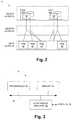
- FIG. 3shows an example configuration of the processing circuitry 18 from a computer hardware perspective.
- the hardwareincludes one or more processors 50 , memory 52 , and interface circuitry 54 interconnected by data interconnections 56 such as one or more high-speed data buses.
- the interface circuitry 54provides hardware connections to the ports 16 , 20 ( FIG. 1 ) and perhaps other external devices/connections.
- the processor(s) 50 with connected memory 52may also be referred to as “processing circuitry” herein.
- the memory 52stores data and instructions of system software (e.g., operating system) and one or more application programs which are executed by the processor(s) 50 to cause the hardware to function in a software-defined manner.
- the application softwaremay be stored on a non-transitory computer-readable medium such as an optical or magnetic disk, Flash memory or other non-volatile semiconductor memory, etc., from which it is retrieved for execution by the processing circuitry, as generally known in the art.
- FIG. 4illustrates details of the mapper layer 32 , which is structured as a file system. At a high level it is organized into a namespace 60 , a mapper boot tier 62 which has a large virtual address space 64 (e.g., 8 EB (exabytes)) and a set of Root-Idp pages 66 , and a metadata (M-D) tier 68 . Also shown are the PDBs 40 of the data layer, along with associated PDB descriptors (Desc) 70 .
- the namespace layer 60includes modes 72 that map abstract volume identifiers to corresponding extents 74 of the virtual space 64 . Each mode 74 corresponds to a respective volume 36 ( FIG.
- the modes 74are grouped into families (e.g., Family 1 and Family 2 ) as shown.
- the extents 74are mapped to corresponding sets of PDBs 40 by the remaining structure, as described further below after a brief description of FIG. 5 .
- FIG. 5illustrates a logical segmentation of the virtual address space 64 as expressed in the structure of FIG. 4 .
- a block addressis segmented into distinct portions shown as leaf, mid, top, root and virt-phy, from least to most significant, where all but the virt-phy cover regions that are successive multiples of 512 in size.
- a given leaf value(leaf offset) identifies a single 4 KB block in a specific 2 MB range; a given mid value identifies a single 2 MB sub-range of a specific 1 GB range, and so on.
- a virtual-to-physical (virt-phy) mappingmaps a given extent 74 to a specific 256 TB range as well as to one or more 512 GB sub-regions thereof, as explained more below.
- the Root-Idp pages 66have 512 pointers each, as do the top-level pages (TOP) 76 , mid-level pages (MID) 78 , and leaf pages (LEAF) 80 .
- TOPtop-level pages
- MIDmid-level pages
- LEAFleaf pages
- individual extents 74which correspond to modes 72 are mapped to corresponding sets of Root-Idp pointers of the Root-Idp pages 66 , where each Root-Idp pointer points to a respective top-level (TOP) page 76 .
- This mappingis the virtual-to-physical mapping discussed above, and is indicated in FIG.
- each volume 36as a practical matter is constrained to have a size that is a multiple of 512 GB (the region size mapped by a TOP 76 ).
- other structuremay be used to provide finer or coarser size resolution as may be desired.
- each TOP 76has up to 512 pointers to respective MIDs 78 ; and each MID 78 has up to 512 pointers pointing to respective LEAFs 80 .
- the LEAFs 80have pointers to virtual data blocks (VDBs) 82 and entries thereof, as explained more below.
- the VDBs 82provide a level of indirection between the lowest-level mapping of the LEAFS 80 and the PDBs 40 storing the actual data. This indirection provides support for services such as data compression and de-duplication, as explained more below.
- a VDB 82also points to the PDB descriptor 70 of the PDB 40 to which the VDB 82 points. Additionally, the PDB descriptor 70 preferably includes a back-pointer pointing back to the associated VDB 82 , for purposes of repair/recovery as described below.
- a data requestis directed to a particular volume 36 and range of logical addresses thereof, also referred to as “offsets”.
- an mode 72is selected based on the identity of the volume being accessed. The mode selection results in identification of the associated extent 74 and a set of entries (pointers) of a corresponding Root-Idp page 66 . For a volume of less than 512 GB, the ROOT and TOP address segments together specify a particular TOP 76 and MID 78 . Larger volumes may have multiple Root-Idp pointers identifying multiple MIDs 78 .
- the MID address segmentspecifies an individual pointer in a MID 78 that points to a corresponding LEAF 80 , and similarly the LEAF address segment specifies a specific VDB 82 and the PDB 40 to which it points, as well as individual VDB and PDB entries. Additional aspects of operation are described below.
- FIG. 4All of the structure of FIG. 4 is so-called “on-disk” structure, i.e., stored persistently on the same non-volatile storage media that constitutes the devices 20 ( FIG. 1 ). At any given time, some of this structure may be resident in system memory to promote faster operation. There may be an in-memory “metadata cache” for caching such in-memory portions of the structure, and various functions and rules for managing the metadata cache to optimize performance and robustness/resilience. Such techniques are generally known and not elaborated herein.
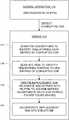
- FIG. 6illustrates certain structure and operation at the level of the VDBs 82 and PDBs 40 .
- two VDBs 82 - 1 , 82 - 2point to a single PDB 40 as well as its associated PDB Descriptor 70 ( FIG. 4 ).
- Each VDB 82contains a respective set of VDB entries 90 , each pointing to a respective PDB entry 92 of the PDB 40 . These are shown as forward pointers 94 .
- forward pointers 94Also shown is the reference from a leaf entry 96 of a leaf page 80 —each leaf entry 96 points to a given VDB 82 as well as to an individual VDB entry 90 thereof.
- Each PDB entry 92also points back (via backward pointers 98 ) to the associated VDB entries.
- the forward pointers 94are used for normal operation, using address bits to find the associated data to satisfy a request.
- the backward pointers 98are used for a metadata rebuilding process performed in response to errone
- the VDB and PDB structureis used in support of data deduplication and/or data compression.
- Data deduplicationis supported by enabling multiple VDB entries 90 to point to the same PDB entry 92 .
- Data compressionis supported by each PDB entry 92 containing a variable-length quantity of data resulting from compression, by a compression algorithm, of a standard-size fixed-length quantity of data. Thus for example a 4 KB block of data may be compressed to a size of something less than 1 KB.
- This variable-length chunkis stored in a PDB entry 92 , and the associated VDB entry 90 identifies both the location of the PDB entry 92 in the PDB 40 as well as the length (e.g., a length less than 1 KB in this example).
- a given VDB entry 90contains a reference count that tracks the number of deduplication references from the respective Leaf IDP pages 80 that point to it. There is a limit to the number of references a given VDB entry 90 can have.
- the VDB entry 90also contains an offset and length for the data that it refers to in the corresponding PDB 40 , as already described. In the case of compression, the length will be less than 4 KB.
- An identifier of the compression typeis also stored within the VDB 82 , and therefore applies to all VDB entries 90 therein.
- FIGS. 7 and 8illustrate structure of the VDBs 82 and PDBs 40 in more detail.
- the VDB entries (VDB ENT) 90 and PDB entries (PDB ENT) 92are shown.
- Each VDB entry 90includes a PDB-entry pointer (PE-PTR) 94 in the form of a starting offset and length for an extent of data in the corresponding PDB 40 .
- Each VDB entry 90also includes other metadata (M-D) 100 .
- Each PDB entry 92includes the corresponding extent of data 102 along with metadata (M-D) 104 , which includes the VDB-entry pointers (VE-PTRs) 98 ( FIG. 6 ) as well as other metadata.
- the data 102is actual file system data stored in this PDB 40 and mapped by the structure of FIG. 4 as explained above.
- FIG. 9illustrates pertinent operation including the repair process that has been mentioned above.
- normal operationoccurs in which the data storage system 12 processes host I/O requests by writing/reading data to/from the devices 20 .
- the data storage system 12both uses and maintains the file-system structure ( FIG. 4 ) of the mapper layer 32 .
- the VE-PTRs 96are added to PDB entries 92 , identifying the corresponding VDB entries 90 .
- a repair operation 112is initiated upon detecting a corrupted VDB 82 during the normal operation 110 .
- corruptedsignifies any condition that makes the VDB 82 unusable for normal operation.
- True data corruptionmay have occurred, i.e., an erroneous modification of its contents, or other conditions may have somehow made the VDB 82 inaccessible or otherwise unusable.
- At 112is the repair operation for repairing the indirect addressing structure ( FIG. 4 ) that has been damaged by corruption of a VDB.
- all PDB descriptors 70are scanned to identify PDBs 40 that store file system data mapped by the corrupted VDB 82 , based on the back-pointers of the PDB descriptors 70 as mentioned above.
- Each identified PDB 40includes a set of PDB entries 92 each having a corresponding backward pointer 98 that identifies a corresponding VDB entry 90 of a corresponding VDB 82 .
- a given PDB 40may be pointed to by multiple VDBs 82 , and thus the set of all PDB entries 92 from these identified PDBs 40 will be referenced from multiple VDBs 82 including both the corrupted VDB 82 as well as undamaged VDBs 82 .
- the PDBs 40 identified in step 114are scanned to identify those PDB entries 92 whose backward pointers 98 refer to VDB entries 90 of the corrupted VDB 82 specifically.
- a replacement VDB 82is created by (1) for each of the PDB entries 92 identified in step 116 , recreating a corresponding VDB entry 90 including a forward pointer 94 to the identified PDB entry 92 , and (2) incorporating the recreated VDB entries 92 into the replacement VDB 82 .
- the replacement VDB 82is incorporated into the indirect addressing structure ( FIG. 4 ) in place of the corrupted VDB 82 .
- This stepincludes updating the associated leaf entries 96 ( FIG. 6 ) to point to the replacement VDB 82 instead of the corrupted VDB 82 .
- the VDB entries 90may also maintain reference counts of references from the Leaf pages 80 , and these must also be recreated and incorporated into the replacement VDB 82 .
- Fixing the reference countsrequires a scan of all the Leaf pages 80 to find all the references to the VDB entries 90 that correspond to the corrupt VDB 82 . Scanning of all the Leaf pages 80 can be done as a regulated background process to completely fix the reference counts in the replacement VDB 82 . Until the background processing is done, the replacement VDB 82 can be marked with a specific state to indicate its rebuilding process. Any normal-path accesses to the replacement VDB 82 can be prevented by checking the state.
Landscapes
- Engineering & Computer Science (AREA)
- Theoretical Computer Science (AREA)
- Quality & Reliability (AREA)
- Physics & Mathematics (AREA)
- General Engineering & Computer Science (AREA)
- General Physics & Mathematics (AREA)
- Information Retrieval, Db Structures And Fs Structures Therefor (AREA)
- Library & Information Science (AREA)
Abstract
Description
Claims (20)
Priority Applications (1)
| Application Number | Priority Date | Filing Date | Title |
|---|---|---|---|
| US16/399,044US11003524B2 (en) | 2019-04-30 | 2019-04-30 | Data storage system with repair of virtual data blocks of internal file system |
Applications Claiming Priority (1)
| Application Number | Priority Date | Filing Date | Title |
|---|---|---|---|
| US16/399,044US11003524B2 (en) | 2019-04-30 | 2019-04-30 | Data storage system with repair of virtual data blocks of internal file system |
Publications (2)
| Publication Number | Publication Date |
|---|---|
| US20200348998A1 US20200348998A1 (en) | 2020-11-05 |
| US11003524B2true US11003524B2 (en) | 2021-05-11 |
Family
ID=73016234
Family Applications (1)
| Application Number | Title | Priority Date | Filing Date |
|---|---|---|---|
| US16/399,044Active2039-08-26US11003524B2 (en) | 2019-04-30 | 2019-04-30 | Data storage system with repair of virtual data blocks of internal file system |
Country Status (1)
| Country | Link |
|---|---|
| US (1) | US11003524B2 (en) |
Families Citing this family (1)
| Publication number | Priority date | Publication date | Assignee | Title |
|---|---|---|---|---|
| US11592996B2 (en)* | 2021-07-23 | 2023-02-28 | EMC IP Holding Company LLC | Online error recovery |
Citations (10)
| Publication number | Priority date | Publication date | Assignee | Title |
|---|---|---|---|---|
| US6973556B2 (en)* | 2000-06-19 | 2005-12-06 | Storage Technology Corporation | Data element including metadata that includes data management information for managing the data element |
| US7475277B1 (en) | 2005-11-10 | 2009-01-06 | Storage Technology Corporation | Automated repair of damaged objects |
| US7546319B1 (en) | 2003-04-28 | 2009-06-09 | Ibrix, Inc. | File system consistency checking in a distributed segmented file system |
| US20090271659A1 (en) | 2008-04-24 | 2009-10-29 | Ulf Troppens | Raid rebuild using file system and block list |
| WO2010050944A1 (en) | 2008-10-30 | 2010-05-06 | Hewlett-Packard Development Company, L.P. | Online checking of data structures of a file system |
| US7730277B1 (en)* | 2004-10-25 | 2010-06-01 | Netapp, Inc. | System and method for using pvbn placeholders in a flexible volume of a storage system |
| US7945726B2 (en) | 2006-05-08 | 2011-05-17 | Emc Corporation | Pre-allocation and hierarchical mapping of data blocks distributed from a first processor to a second processor for use in a file system |
| US8843533B1 (en) | 2008-11-12 | 2014-09-23 | Netapp, Inc. | File system consistency check system |
| US9020987B1 (en)* | 2011-06-29 | 2015-04-28 | Emc Corporation | Managing updating of metadata of file systems |
| US9547659B1 (en)* | 2015-08-11 | 2017-01-17 | International Business Machines Corporation | Reducing the cost of update, delete, and append-only insert operations in a database |
- 2019
- 2019-04-30USUS16/399,044patent/US11003524B2/enactiveActive
Patent Citations (10)
| Publication number | Priority date | Publication date | Assignee | Title |
|---|---|---|---|---|
| US6973556B2 (en)* | 2000-06-19 | 2005-12-06 | Storage Technology Corporation | Data element including metadata that includes data management information for managing the data element |
| US7546319B1 (en) | 2003-04-28 | 2009-06-09 | Ibrix, Inc. | File system consistency checking in a distributed segmented file system |
| US7730277B1 (en)* | 2004-10-25 | 2010-06-01 | Netapp, Inc. | System and method for using pvbn placeholders in a flexible volume of a storage system |
| US7475277B1 (en) | 2005-11-10 | 2009-01-06 | Storage Technology Corporation | Automated repair of damaged objects |
| US7945726B2 (en) | 2006-05-08 | 2011-05-17 | Emc Corporation | Pre-allocation and hierarchical mapping of data blocks distributed from a first processor to a second processor for use in a file system |
| US20090271659A1 (en) | 2008-04-24 | 2009-10-29 | Ulf Troppens | Raid rebuild using file system and block list |
| WO2010050944A1 (en) | 2008-10-30 | 2010-05-06 | Hewlett-Packard Development Company, L.P. | Online checking of data structures of a file system |
| US8843533B1 (en) | 2008-11-12 | 2014-09-23 | Netapp, Inc. | File system consistency check system |
| US9020987B1 (en)* | 2011-06-29 | 2015-04-28 | Emc Corporation | Managing updating of metadata of file systems |
| US9547659B1 (en)* | 2015-08-11 | 2017-01-17 | International Business Machines Corporation | Reducing the cost of update, delete, and append-only insert operations in a database |
Also Published As
| Publication number | Publication date |
|---|---|
| US20200348998A1 (en) | 2020-11-05 |
Similar Documents
| Publication | Publication Date | Title |
|---|---|---|
| US10649910B2 (en) | Persistent memory for key-value storage | |
| US10289545B2 (en) | Hybrid checkpointed memory | |
| US9092325B2 (en) | Fast block device and methodology | |
| US9134917B2 (en) | Hybrid media storage system architecture | |
| EP3191957B1 (en) | Low-overhead restartable merge operation with efficient crash recovery | |
| US8095577B1 (en) | Managing metadata | |
| US10176190B2 (en) | Data integrity and loss resistance in high performance and high capacity storage deduplication | |
| US8850114B2 (en) | Storage array controller for flash-based storage devices | |
| US10956071B2 (en) | Container key value store for data storage devices | |
| US20160077744A1 (en) | Deferred reference count update technique for low overhead volume metadata | |
| US11977452B2 (en) | Efficient IO processing in a storage system with instant snapshot, XCOPY, and UNMAP capabilities | |
| US11960458B2 (en) | Deduplicating data at sub-block granularity | |
| US20150253999A1 (en) | METHOD AND APPARATUS FOR DE-DUPLICATION FOR SOLID STATE DISKs (SSDs) | |
| US20150324281A1 (en) | System and method of implementing an object storage device on a computer main memory system | |
| US10990486B2 (en) | Data storage system with repair of mid-level mapping blocks of internal file system | |
| US8402247B2 (en) | Remapping of data addresses for large capacity low-latency random read memory | |
| US20210034292A1 (en) | Encoded virtual block deferred reference counting | |
| US11003524B2 (en) | Data storage system with repair of virtual data blocks of internal file system | |
| US10409518B1 (en) | Reordered local data deduplication in storage devices | |
| US11112987B2 (en) | Optmizing data deduplication | |
| US10089032B1 (en) | Controlling write sizes to reduce flash wear | |
| US12411810B1 (en) | Efficient removal of stale entries from on-drive deduplication hash tables using hash prefix indexing | |
| CN117806550A (en) | A solid-state disk array system that supports cross-disk address remapping |
Legal Events
| Date | Code | Title | Description |
|---|---|---|---|
| FEPP | Fee payment procedure | Free format text:ENTITY STATUS SET TO UNDISCOUNTED (ORIGINAL EVENT CODE: BIG.); ENTITY STATUS OF PATENT OWNER: LARGE ENTITY | |
| AS | Assignment | Owner name:EMC IP HOLDING COMPANY LLC, MASSACHUSETTS Free format text:ASSIGNMENT OF ASSIGNORS INTEREST;ASSIGNORS:MATHEWS, ALEXANDER S.;CHAWLA, ROHIT K.;PATEL, DIXITKUMAR;AND OTHERS;SIGNING DATES FROM 20190430 TO 20190517;REEL/FRAME:049250/0793 | |
| AS | Assignment | Owner name:CREDIT SUISSE AG, CAYMAN ISLANDS BRANCH, NORTH CAROLINA Free format text:SECURITY AGREEMENT;ASSIGNORS:DELL PRODUCTS L.P.;EMC CORPORATION;EMC IP HOLDING COMPANY LLC;AND OTHERS;REEL/FRAME:050405/0534 Effective date:20190917 | |
| AS | Assignment | Owner name:THE BANK OF NEW YORK MELLON TRUST COMPANY, N.A., AS COLLATERAL AGENT, TEXAS Free format text:PATENT SECURITY AGREEMENT (NOTES);ASSIGNORS:DELL PRODUCTS L.P.;EMC CORPORATION;EMC IP HOLDING COMPANY LLC;AND OTHERS;REEL/FRAME:050724/0466 Effective date:20191010 | |
| AS | Assignment | Owner name:THE BANK OF NEW YORK MELLON TRUST COMPANY, N.A., TEXAS Free format text:SECURITY AGREEMENT;ASSIGNORS:CREDANT TECHNOLOGIES INC.;DELL INTERNATIONAL L.L.C.;DELL MARKETING L.P.;AND OTHERS;REEL/FRAME:053546/0001 Effective date:20200409 | |
| AS | Assignment | Owner name:THE BANK OF NEW YORK MELLON TRUST COMPANY, N.A., AS COLLATERAL AGENT, TEXAS Free format text:SECURITY INTEREST;ASSIGNORS:DELL PRODUCTS L.P.;EMC CORPORATION;EMC IP HOLDING COMPANY LLC;REEL/FRAME:053311/0169 Effective date:20200603 | |
| STPP | Information on status: patent application and granting procedure in general | Free format text:NOTICE OF ALLOWANCE MAILED -- APPLICATION RECEIVED IN OFFICE OF PUBLICATIONS | |
| STPP | Information on status: patent application and granting procedure in general | Free format text:PUBLICATIONS -- ISSUE FEE PAYMENT VERIFIED | |
| STCF | Information on status: patent grant | Free format text:PATENTED CASE | |
| AS | Assignment | Owner name:WYSE TECHNOLOGY L.L.C., CALIFORNIA Free format text:RELEASE OF SECURITY INTEREST AT REEL 050405 FRAME 0534;ASSIGNOR:CREDIT SUISSE AG, CAYMAN ISLANDS BRANCH;REEL/FRAME:058001/0001 Effective date:20211101 Owner name:EMC IP HOLDING COMPANY LLC, TEXAS Free format text:RELEASE OF SECURITY INTEREST AT REEL 050405 FRAME 0534;ASSIGNOR:CREDIT SUISSE AG, CAYMAN ISLANDS BRANCH;REEL/FRAME:058001/0001 Effective date:20211101 Owner name:EMC CORPORATION, MASSACHUSETTS Free format text:RELEASE OF SECURITY INTEREST AT REEL 050405 FRAME 0534;ASSIGNOR:CREDIT SUISSE AG, CAYMAN ISLANDS BRANCH;REEL/FRAME:058001/0001 Effective date:20211101 Owner name:DELL PRODUCTS L.P., TEXAS Free format text:RELEASE OF SECURITY INTEREST AT REEL 050405 FRAME 0534;ASSIGNOR:CREDIT SUISSE AG, CAYMAN ISLANDS BRANCH;REEL/FRAME:058001/0001 Effective date:20211101 | |
| AS | Assignment | Owner name:DELL MARKETING CORPORATION (SUCCESSOR-IN-INTEREST TO WYSE TECHNOLOGY L.L.C.), TEXAS Free format text:RELEASE OF SECURITY INTEREST IN PATENTS PREVIOUSLY RECORDED AT REEL/FRAME (050724/0466);ASSIGNOR:THE BANK OF NEW YORK MELLON TRUST COMPANY, N.A., AS NOTES COLLATERAL AGENT;REEL/FRAME:060753/0486 Effective date:20220329 Owner name:EMC IP HOLDING COMPANY LLC, TEXAS Free format text:RELEASE OF SECURITY INTEREST IN PATENTS PREVIOUSLY RECORDED AT REEL/FRAME (050724/0466);ASSIGNOR:THE BANK OF NEW YORK MELLON TRUST COMPANY, N.A., AS NOTES COLLATERAL AGENT;REEL/FRAME:060753/0486 Effective date:20220329 Owner name:EMC CORPORATION, MASSACHUSETTS Free format text:RELEASE OF SECURITY INTEREST IN PATENTS PREVIOUSLY RECORDED AT REEL/FRAME (050724/0466);ASSIGNOR:THE BANK OF NEW YORK MELLON TRUST COMPANY, N.A., AS NOTES COLLATERAL AGENT;REEL/FRAME:060753/0486 Effective date:20220329 Owner name:DELL PRODUCTS L.P., TEXAS Free format text:RELEASE OF SECURITY INTEREST IN PATENTS PREVIOUSLY RECORDED AT REEL/FRAME (050724/0466);ASSIGNOR:THE BANK OF NEW YORK MELLON TRUST COMPANY, N.A., AS NOTES COLLATERAL AGENT;REEL/FRAME:060753/0486 Effective date:20220329 Owner name:EMC IP HOLDING COMPANY LLC, TEXAS Free format text:RELEASE OF SECURITY INTEREST IN PATENTS PREVIOUSLY RECORDED AT REEL/FRAME (053311/0169);ASSIGNOR:THE BANK OF NEW YORK MELLON TRUST COMPANY, N.A., AS NOTES COLLATERAL AGENT;REEL/FRAME:060438/0742 Effective date:20220329 Owner name:EMC CORPORATION, MASSACHUSETTS Free format text:RELEASE OF SECURITY INTEREST IN PATENTS PREVIOUSLY RECORDED AT REEL/FRAME (053311/0169);ASSIGNOR:THE BANK OF NEW YORK MELLON TRUST COMPANY, N.A., AS NOTES COLLATERAL AGENT;REEL/FRAME:060438/0742 Effective date:20220329 Owner name:DELL PRODUCTS L.P., TEXAS Free format text:RELEASE OF SECURITY INTEREST IN PATENTS PREVIOUSLY RECORDED AT REEL/FRAME (053311/0169);ASSIGNOR:THE BANK OF NEW YORK MELLON TRUST COMPANY, N.A., AS NOTES COLLATERAL AGENT;REEL/FRAME:060438/0742 Effective date:20220329 Owner name:DELL MARKETING L.P. (ON BEHALF OF ITSELF AND AS SUCCESSOR-IN-INTEREST TO CREDANT TECHNOLOGIES, INC.), TEXAS Free format text:RELEASE OF SECURITY INTEREST IN PATENTS PREVIOUSLY RECORDED AT REEL/FRAME (053546/0001);ASSIGNOR:THE BANK OF NEW YORK MELLON TRUST COMPANY, N.A., AS NOTES COLLATERAL AGENT;REEL/FRAME:071642/0001 Effective date:20220329 Owner name:DELL INTERNATIONAL L.L.C., TEXAS Free format text:RELEASE OF SECURITY INTEREST IN PATENTS PREVIOUSLY RECORDED AT REEL/FRAME (053546/0001);ASSIGNOR:THE BANK OF NEW YORK MELLON TRUST COMPANY, N.A., AS NOTES COLLATERAL AGENT;REEL/FRAME:071642/0001 Effective date:20220329 Owner name:DELL PRODUCTS L.P., TEXAS Free format text:RELEASE OF SECURITY INTEREST IN PATENTS PREVIOUSLY RECORDED AT REEL/FRAME (053546/0001);ASSIGNOR:THE BANK OF NEW YORK MELLON TRUST COMPANY, N.A., AS NOTES COLLATERAL AGENT;REEL/FRAME:071642/0001 Effective date:20220329 Owner name:DELL USA L.P., TEXAS Free format text:RELEASE OF SECURITY INTEREST IN PATENTS PREVIOUSLY RECORDED AT REEL/FRAME (053546/0001);ASSIGNOR:THE BANK OF NEW YORK MELLON TRUST COMPANY, N.A., AS NOTES COLLATERAL AGENT;REEL/FRAME:071642/0001 Effective date:20220329 Owner name:EMC CORPORATION, MASSACHUSETTS Free format text:RELEASE OF SECURITY INTEREST IN PATENTS PREVIOUSLY RECORDED AT REEL/FRAME (053546/0001);ASSIGNOR:THE BANK OF NEW YORK MELLON TRUST COMPANY, N.A., AS NOTES COLLATERAL AGENT;REEL/FRAME:071642/0001 Effective date:20220329 Owner name:DELL MARKETING CORPORATION (SUCCESSOR-IN-INTEREST TO FORCE10 NETWORKS, INC. AND WYSE TECHNOLOGY L.L.C.), TEXAS Free format text:RELEASE OF SECURITY INTEREST IN PATENTS PREVIOUSLY RECORDED AT REEL/FRAME (053546/0001);ASSIGNOR:THE BANK OF NEW YORK MELLON TRUST COMPANY, N.A., AS NOTES COLLATERAL AGENT;REEL/FRAME:071642/0001 Effective date:20220329 Owner name:EMC IP HOLDING COMPANY LLC, TEXAS Free format text:RELEASE OF SECURITY INTEREST IN PATENTS PREVIOUSLY RECORDED AT REEL/FRAME (053546/0001);ASSIGNOR:THE BANK OF NEW YORK MELLON TRUST COMPANY, N.A., AS NOTES COLLATERAL AGENT;REEL/FRAME:071642/0001 Effective date:20220329 | |
| MAFP | Maintenance fee payment | Free format text:PAYMENT OF MAINTENANCE FEE, 4TH YEAR, LARGE ENTITY (ORIGINAL EVENT CODE: M1551); ENTITY STATUS OF PATENT OWNER: LARGE ENTITY Year of fee payment:4 |