US11003476B2 - Entity database historical data - Google Patents
Entity database historical dataDownload PDFInfo
- Publication number
- US11003476B2 US11003476B2US15/423,477US201715423477AUS11003476B2US 11003476 B2US11003476 B2US 11003476B2US 201715423477 AUS201715423477 AUS 201715423477AUS 11003476 B2US11003476 B2US 11003476B2
- Authority
- US
- United States
- Prior art keywords
- entity
- entities
- time segment
- particular embodiments
- update
- Prior art date
- Legal status (The legal status is an assumption and is not a legal conclusion. Google has not performed a legal analysis and makes no representation as to the accuracy of the status listed.)
- Active, expires
Links
Images


Classifications
- G—PHYSICS
- G06—COMPUTING OR CALCULATING; COUNTING
- G06F—ELECTRIC DIGITAL DATA PROCESSING
- G06F9/00—Arrangements for program control, e.g. control units
- G06F9/06—Arrangements for program control, e.g. control units using stored programs, i.e. using an internal store of processing equipment to receive or retain programs
- G06F9/44—Arrangements for executing specific programs
- G06F9/455—Emulation; Interpretation; Software simulation, e.g. virtualisation or emulation of application or operating system execution engines
- G06F9/45533—Hypervisors; Virtual machine monitors
- G06F9/45558—Hypervisor-specific management and integration aspects
- G—PHYSICS
- G06—COMPUTING OR CALCULATING; COUNTING
- G06F—ELECTRIC DIGITAL DATA PROCESSING
- G06F11/00—Error detection; Error correction; Monitoring
- G06F11/07—Responding to the occurrence of a fault, e.g. fault tolerance
- G06F11/14—Error detection or correction of the data by redundancy in operation
- G—PHYSICS
- G06—COMPUTING OR CALCULATING; COUNTING
- G06F—ELECTRIC DIGITAL DATA PROCESSING
- G06F11/00—Error detection; Error correction; Monitoring
- G06F11/07—Responding to the occurrence of a fault, e.g. fault tolerance
- G06F11/16—Error detection or correction of the data by redundancy in hardware
- G06F11/20—Error detection or correction of the data by redundancy in hardware using active fault-masking, e.g. by switching out faulty elements or by switching in spare elements
- G06F11/2053—Error detection or correction of the data by redundancy in hardware using active fault-masking, e.g. by switching out faulty elements or by switching in spare elements where persistent mass storage functionality or persistent mass storage control functionality is redundant
- G06F11/2094—Redundant storage or storage space
- G—PHYSICS
- G06—COMPUTING OR CALCULATING; COUNTING
- G06F—ELECTRIC DIGITAL DATA PROCESSING
- G06F16/00—Information retrieval; Database structures therefor; File system structures therefor
- G—PHYSICS
- G06—COMPUTING OR CALCULATING; COUNTING
- G06F—ELECTRIC DIGITAL DATA PROCESSING
- G06F16/00—Information retrieval; Database structures therefor; File system structures therefor
- G06F16/20—Information retrieval; Database structures therefor; File system structures therefor of structured data, e.g. relational data
- G06F16/21—Design, administration or maintenance of databases
- G06F16/211—Schema design and management
- G06F16/212—Schema design and management with details for data modelling support
- G—PHYSICS
- G06—COMPUTING OR CALCULATING; COUNTING
- G06F—ELECTRIC DIGITAL DATA PROCESSING
- G06F16/00—Information retrieval; Database structures therefor; File system structures therefor
- G06F16/20—Information retrieval; Database structures therefor; File system structures therefor of structured data, e.g. relational data
- G06F16/21—Design, administration or maintenance of databases
- G06F16/219—Managing data history or versioning
- G—PHYSICS
- G06—COMPUTING OR CALCULATING; COUNTING
- G06F—ELECTRIC DIGITAL DATA PROCESSING
- G06F16/00—Information retrieval; Database structures therefor; File system structures therefor
- G06F16/20—Information retrieval; Database structures therefor; File system structures therefor of structured data, e.g. relational data
- G06F16/23—Updating
- G06F16/2358—Change logging, detection, and notification
- G—PHYSICS
- G06—COMPUTING OR CALCULATING; COUNTING
- G06F—ELECTRIC DIGITAL DATA PROCESSING
- G06F16/00—Information retrieval; Database structures therefor; File system structures therefor
- G06F16/20—Information retrieval; Database structures therefor; File system structures therefor of structured data, e.g. relational data
- G06F16/23—Updating
- G06F16/2379—Updates performed during online database operations; commit processing
- G—PHYSICS
- G06—COMPUTING OR CALCULATING; COUNTING
- G06F—ELECTRIC DIGITAL DATA PROCESSING
- G06F16/00—Information retrieval; Database structures therefor; File system structures therefor
- G06F16/20—Information retrieval; Database structures therefor; File system structures therefor of structured data, e.g. relational data
- G06F16/24—Querying
- G06F16/245—Query processing
- G06F16/2457—Query processing with adaptation to user needs
- G06F16/24578—Query processing with adaptation to user needs using ranking
- G—PHYSICS
- G06—COMPUTING OR CALCULATING; COUNTING
- G06F—ELECTRIC DIGITAL DATA PROCESSING
- G06F16/00—Information retrieval; Database structures therefor; File system structures therefor
- G06F16/20—Information retrieval; Database structures therefor; File system structures therefor of structured data, e.g. relational data
- G06F16/26—Visual data mining; Browsing structured data
- G—PHYSICS
- G06—COMPUTING OR CALCULATING; COUNTING
- G06F—ELECTRIC DIGITAL DATA PROCESSING
- G06F16/00—Information retrieval; Database structures therefor; File system structures therefor
- G06F16/20—Information retrieval; Database structures therefor; File system structures therefor of structured data, e.g. relational data
- G06F16/27—Replication, distribution or synchronisation of data between databases or within a distributed database system; Distributed database system architectures therefor
- G—PHYSICS
- G06—COMPUTING OR CALCULATING; COUNTING
- G06F—ELECTRIC DIGITAL DATA PROCESSING
- G06F16/00—Information retrieval; Database structures therefor; File system structures therefor
- G06F16/20—Information retrieval; Database structures therefor; File system structures therefor of structured data, e.g. relational data
- G06F16/28—Databases characterised by their database models, e.g. relational or object models
- G06F16/284—Relational databases
- G06F16/285—Clustering or classification
- G—PHYSICS
- G06—COMPUTING OR CALCULATING; COUNTING
- G06F—ELECTRIC DIGITAL DATA PROCESSING
- G06F16/00—Information retrieval; Database structures therefor; File system structures therefor
- G06F16/90—Details of database functions independent of the retrieved data types
- G06F16/95—Retrieval from the web
- G06F16/953—Querying, e.g. by the use of web search engines
- G06F16/9535—Search customisation based on user profiles and personalisation
- G—PHYSICS
- G06—COMPUTING OR CALCULATING; COUNTING
- G06F—ELECTRIC DIGITAL DATA PROCESSING
- G06F16/00—Information retrieval; Database structures therefor; File system structures therefor
- G06F16/90—Details of database functions independent of the retrieved data types
- G06F16/95—Retrieval from the web
- G06F16/953—Querying, e.g. by the use of web search engines
- G06F16/9538—Presentation of query results
- H—ELECTRICITY
- H04—ELECTRIC COMMUNICATION TECHNIQUE
- H04L—TRANSMISSION OF DIGITAL INFORMATION, e.g. TELEGRAPHIC COMMUNICATION
- H04L67/00—Network arrangements or protocols for supporting network services or applications
- H04L67/01—Protocols
- H04L67/10—Protocols in which an application is distributed across nodes in the network
- H04L67/1097—Protocols in which an application is distributed across nodes in the network for distributed storage of data in networks, e.g. transport arrangements for network file system [NFS], storage area networks [SAN] or network attached storage [NAS]
- H—ELECTRICITY
- H04—ELECTRIC COMMUNICATION TECHNIQUE
- H04W—WIRELESS COMMUNICATION NETWORKS
- H04W4/00—Services specially adapted for wireless communication networks; Facilities therefor
- H04W4/60—Subscription-based services using application servers or record carriers, e.g. SIM application toolkits
- G—PHYSICS
- G06—COMPUTING OR CALCULATING; COUNTING
- G06F—ELECTRIC DIGITAL DATA PROCESSING
- G06F9/00—Arrangements for program control, e.g. control units
- G06F9/06—Arrangements for program control, e.g. control units using stored programs, i.e. using an internal store of processing equipment to receive or retain programs
- G06F9/44—Arrangements for executing specific programs
- G06F9/455—Emulation; Interpretation; Software simulation, e.g. virtualisation or emulation of application or operating system execution engines
- G06F9/45533—Hypervisors; Virtual machine monitors
- G06F9/45558—Hypervisor-specific management and integration aspects
- G06F2009/45579—I/O management, e.g. providing access to device drivers or storage
- G—PHYSICS
- G06—COMPUTING OR CALCULATING; COUNTING
- G06F—ELECTRIC DIGITAL DATA PROCESSING
- G06F9/00—Arrangements for program control, e.g. control units
- G06F9/06—Arrangements for program control, e.g. control units using stored programs, i.e. using an internal store of processing equipment to receive or retain programs
- G06F9/44—Arrangements for executing specific programs
- G06F9/455—Emulation; Interpretation; Software simulation, e.g. virtualisation or emulation of application or operating system execution engines
- G06F9/45533—Hypervisors; Virtual machine monitors
- G06F9/45558—Hypervisor-specific management and integration aspects
- G06F2009/45583—Memory management, e.g. access or allocation
- G—PHYSICS
- G06—COMPUTING OR CALCULATING; COUNTING
- G06F—ELECTRIC DIGITAL DATA PROCESSING
- G06F2201/00—Indexing scheme relating to error detection, to error correction, and to monitoring
- G06F2201/835—Timestamp
- G—PHYSICS
- G06—COMPUTING OR CALCULATING; COUNTING
- G06F—ELECTRIC DIGITAL DATA PROCESSING
- G06F3/00—Input arrangements for transferring data to be processed into a form capable of being handled by the computer; Output arrangements for transferring data from processing unit to output unit, e.g. interface arrangements
- G06F3/01—Input arrangements or combined input and output arrangements for interaction between user and computer
- G06F3/048—Interaction techniques based on graphical user interfaces [GUI]
- G06F3/0484—Interaction techniques based on graphical user interfaces [GUI] for the control of specific functions or operations, e.g. selecting or manipulating an object, an image or a displayed text element, setting a parameter value or selecting a range
- G06F3/04842—Selection of displayed objects or displayed text elements
- G—PHYSICS
- G06—COMPUTING OR CALCULATING; COUNTING
- G06F—ELECTRIC DIGITAL DATA PROCESSING
- G06F3/00—Input arrangements for transferring data to be processed into a form capable of being handled by the computer; Output arrangements for transferring data from processing unit to output unit, e.g. interface arrangements
- G06F3/01—Input arrangements or combined input and output arrangements for interaction between user and computer
- G06F3/048—Interaction techniques based on graphical user interfaces [GUI]
- G06F3/0484—Interaction techniques based on graphical user interfaces [GUI] for the control of specific functions or operations, e.g. selecting or manipulating an object, an image or a displayed text element, setting a parameter value or selecting a range
- G06F3/04845—Interaction techniques based on graphical user interfaces [GUI] for the control of specific functions or operations, e.g. selecting or manipulating an object, an image or a displayed text element, setting a parameter value or selecting a range for image manipulation, e.g. dragging, rotation, expansion or change of colour
Definitions
- This disclosurerelates generally to virtualization environments.
- a “virtual machine” or a “VM”refers to a specific software-based implementation of a machine in a virtualization environment, in which the hardware resources of a real computer (e.g., CPU, memory, etc.) are virtualized or transformed into the underlying support for the fully functional virtual machine that can run its own operating system and applications on the underlying physical resources just like a real computer.
- a real computere.g., CPU, memory, etc.
- Virtualizationworks by inserting a thin layer of software directly on the computer hardware or on a host operating system.
- This layer of softwarecontains a virtual machine monitor or “hypervisor” that allocates hardware resources dynamically and transparently.
- Multiple operating systemsrun concurrently on a single physical computer and share hardware resources with each other.
- a virtual machineis completely compatible with most standard operating systems, applications, and device drivers.
- Most modern implementationsallow several operating systems and applications to safely run at the same time on a single computer, with each having access to the resources it needs when it needs them.
- Virtualizationallows one to run multiple virtual machines on a single physical machine, with each virtual machine sharing the resources of that one physical computer across multiple environments. Different virtual machines can run different operating systems and multiple applications on the same physical computer.
- certain virtualization environmentsmay not only utilize the processing power of the physical computing devices but also aggregate storage capacity across the individual physical computing devices to create a logical storage pool, wherein the data is distributed across the physical computing devices, yet appears to the virtual machines to be part of the system that the virtual machine is hosted on.
- Such systemsmay utilize metadata, which may be distributed and replicated any number of times across the system, to locate specific data within the logical storage pool.
- clustered systemswherein the resources of the group are pooled to provide logically combined, but physically separate systems.
- Embodiments of the present inventionintroduce a user interface to display information about entities, their relationships, attributes, and stats in a virtualization environment.
- a virtualization environmentmay include a plurality of host machines, each of the host machines comprising a hypervisor, one or more user virtual machines (UVMs) and a virtual machine controller.
- the virtualization environmentfurther includes one or more virtual disks comprising a plurality of storage devices, the one or more virtual disks being accessible by the virtual machine controllers.
- the virtual machine controllersconduct I/O transactions with the one or more virtual disks.
- a system for managing the virtualization environmentis operable to store an entity-relationship graph representing elements in the virtualization environment. Each of the elements is represented by an entity-type node in the entity-relationship graph, and relationships between the elements are represented by edges between the nodes.
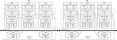
- FIG. 1Aillustrates a clustered virtualization environment according to some embodiments.
- FIG. 1Billustrates data flow within a clustered virtualization environment according to some embodiments.
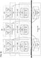
- FIG. 2illustrates the basic pattern of an entity relationship graph according to some embodiments.
- FIG. 3Aillustrates an example entity-relationship graph for entities associated with a virtualization system according to some embodiments.
- FIG. 3Billustrates another example entity-relationship graph for entities associated with a virtualization system according to some embodiments.
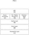
- FIG. 4illustrates an example architecture for an entity database according to some embodiments.
- FIG. 5illustrates an example entity trail for a user virtual machine entity associated with a virtualization environment according to some embodiments.
- FIG. 6illustrates an example context anchor entity ranking according to some embodiments.
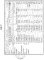
- FIG. 7shows an example client user interface illustrating a list of virtual machines in a virtualization environment with associated attribute values according to some embodiments.
- FIG. 8shows an example client user interface illustrating selection of virtual machines in a virtualization environment according to some embodiments.
- FIG. 9shows an example client user interface illustrating filtering of entities and attributes in a search feature according to some embodiments.
- FIG. 10shows an example client user interface illustrating grouping entities and attributes in a search feature according to some embodiments.
- FIG. 11illustrates a UI displaying labels applied to the selected VM-type entities.
- FIG. 12shows an example client user interface illustrating a statistics display based on grouping and derived metrics according to some embodiments.
- FIG. 13illustrates sample statistics for the overall virtualization environment that may be maintained by the entity database according to some embodiments.
- FIG. 14illustrates a UI displaying a graphical overview representation of current state and other information for the selected and grouped VM-type entities.
- FIG. 15illustrates a UI displaying a graphical overview representation of current state and other information for a filtered subset of the VM-type entities currently existing in the virtualization environment.
- FIG. 16illustrates an example of range-based replication according to some embodiments.
- FIG. 17illustrates a block diagram of a computing system suitable for implementing particular embodiments.
- FIG. 1Aillustrates a clustered virtualization system 100 according to particular embodiments.
- the architecture of FIG. 1Acan be implemented for a distributed platform that contains multiple host machines 101 a - c that manage multiple tiers of storage.
- the multiple tiers of storagemay include storage that is accessible through network 140 , such as, by way of example and not limitation, cloud storage 126 (e.g., which may be accessible through the Internet), network-attached storage (NAS) 128 (e.g., which may be accessible through a LAN), or a storage area network (SAN).
- cloud storage 126e.g., which may be accessible through the Internet
- NASnetwork-attached storage
- SANstorage area network
- the present embodimentalso permits local storage 122 a - c that is incorporated into or directly attached to the host machine and/or appliance to be managed as part of storage pool 160 .
- SSDsSolid State Drives 125
- HDDsHard Disk Drives 127
- spindle drivesoptical disk drives
- external drivese.g., a storage device connected to a host machine via a native drive interface or a serial attached SCSI interface
- storage pool 160e.g., a storage device connected to a host machine via a native drive interface or a serial attached SCSI interface
- Virtual disksmay be structured from the physical storage devices in storage pool 160 , as described in more detail below.
- vDiskrefers to the storage abstraction that is exposed by a Controller/Service VM (CVM) 110 to be used by a user VM 105 .
- CVMController/Service VM
- the vDiskmay be exposed via iSCSI (“internet small computer system interface”) or NFS (“network file system”) and is mounted as a virtual disk on the user VM.
- vDisksmay be organized into one or more volume groups (VGs).
- the virtualization environmentmay include two or more clusters.
- Each host machine 101 a - cmay run virtualization software, such as VMWARE ESX(I), MICROSOFT HYPER-V, REDHAT KVM, or NUTANIX AHV.
- the virtualization softwareincludes hypervisor 130 a - c to create, manage, and destroy user VMs 105 , as well as managing the interactions between the underlying hardware and user VMs 105 .
- User VMs 105may run one or more applications that may operate as “clients” with respect to other elements within virtualization system 100 .
- a hypervisormay connect to network 140 .
- a host machine 101may be a physical hardware computing device; in particular embodiments, a host machine 101 may be a virtual machine.
- CVMs 110 a - care used to manage storage and input/output (“I/O”) activities according to particular embodiments. These special VMs act as the storage controller in the currently described architecture. Multiple such storage controllers may coordinate within a cluster to form a unified storage controller system.
- CVMs 110may run as virtual machines on the various host machines 101 , and work together to form a distributed system 110 that manages all the storage resources, including local storage 122 , NAS 128 , and cloud storage 126 .
- the CVMsmay connect to network 140 directly, or via a hypervisor. Since the CVMs run independent of hypervisors 130 a - c , this means that the current approach can be used and implemented within any virtual machine architecture, since the CVMs of particular embodiments can be used in conjunction with any hypervisor from any virtualization vendor.
- a host machinemay be designated as a leader node within a cluster of host machines.
- host machine 101 bmay be a leader node.
- a leader nodemay have a software component designated to perform operations of the leader.
- CVM 110 b on host machine 101 bmay be designated to perform such operations.
- a leadermay be responsible for monitoring or handling requests from other host machines or software components on other host machines throughout the virtualized environment. If a leader fails, a new leader may be designated.
- a management module(e.g., in the form of an agent) may be running on the leader node.
- Each CVM 110 a - cexports one or more block devices or NFS server targets that appear as disks to user VMs 105 a - c . These disks are virtual, since they are implemented by the software running inside CVMs 110 a - c . Thus, to user VMs 105 a - c , CVMs 110 a - c appear to be exporting a clustered storage appliance that contains some disks. All user data (including the operating system) in the user VMs 105 a - c and reside on these virtual disks.
- FIG. 1Billustrates data flow within an example clustered virtualization system 100 according to particular embodiments.
- one or more user VMs and a CVMmay run on each host machine 101 along with a hypervisor.
- I/O operationse.g., a read operation or a write operation
- the I/O commands of the user VMmay be sent to the hypervisor running on the same host machine as the user VM.
- the hypervisormay present to the virtual machines an emulated storage controller, receive an I/O command and facilitate the performance of the I/O command (e.g., via interfacing with storage that is the object of the command, or passing the command to a service that will perform the I/O command).
- An emulated storage controllermay facilitate I/O operations between a user VM and a vDisk.
- a vDiskmay present to a user VM as one or more discrete storage drives, but each vDisk may correspond to any part of one or more drives within storage pool 160 .
- CVM 110 a - cmay present an emulated storage controller either to the hypervisor or to user VMs to facilitate I/O operations.
- CVM 110 a - cmay be connected to storage within storage pool 160 .
- CVM 110 amay have the ability to perform I/O operations using local storage 122 a within the same host machine 101 a , by connecting via network 140 to cloud storage 126 or NAS 128 , or by connecting via network 140 to local storage 122 b - c within another host machine 101 b - c (e.g., via connecting to another CVM 110 b or 110 c ).
- any suitable computing system 1700may be used to implement a host machine 101 .
- the clustered virtualization environmentmay include a distributed entity database for storing datacenter entities and the relationships between them, as represented by an entity-relationship graph.
- An entity databasemay support such an entity-relationship model by storing information related to the entity-relationship graph, such as entities, entity relationships, and time series information and statistics.
- the databasemay be sharded (a.k.a. distributed) across multiple nodes, and may have a query model optimized for the entity-relationship model that supports querying current and historical data, queries for keyword searches, watches for notifying clients on entity updates, and synchronization of data between database instances.
- FIG. 2illustrates the basic pattern of an entity-relationship graph 200 , which may comprise an entity-type node 210 (e.g., a parent entity-type node) connected to a child entity-type node 212 .
- entity-type node 210e.g., a parent entity-type node
- a plurality of activity-type nodesmay be connected to entity-type node 210 , including an action-type node 220 , an alert-type node 222 , a metrics-type node 224 , and an attributes-type node 226 .
- each entity-type nodee.g., entity type node 210 , child entity-type node 212 , etc.
- each node typecan comprise one or more nodes of that node type.
- each entitymay have its own properties.
- each entitymay also inherit properties from related entities (e.g., inheriting available actions from a parent).
- certain properties of an entitymay represent the aggregated properties of its child entities (e.g., metrics data for a cluster entity may comprise the aggregated metrics data from its child entity nodes). Values for different attributes and/or metrics data for an entity may be generated by different sources (e.g., different services running in the virtualization environment and/or other entities).
- Particular entitiesmay retain historical data relating to changes in its properties and/or metrics data (e.g., tracked statistical information). Such historical data may be retained together with timestamp information so that the evolving state of the virtualization environment is captured in an entity trail, as discussed further in relation to FIG. 5 .
- metrics datae.g., tracked statistical information
- FIG. 3Aillustrates an example entity-relationship graph 300 for entities associated with virtualization system 100 .
- entity-type nodesmay include a multi-cluster-type node 330 , a cluster-type node 332 , a host-type node 334 , a virtual-machine-type node 336 , a virtual-disk-type node 338 , a protection-domain-type node 340 , a container-type node 342 , a network-interface-card-type node 344 , a disk-type node 346 , and a storage-pool-type node 348 .
- the direction of the edge connecting the nodesindicates a child-parent relationship (e.g., the arrow goes from a child node to a parent node).
- cluster-type node 332is a child node of multi-cluster-type node 330 and the parent node of protection-domain-type node 340 and container-type node 342 .
- virtual-machine-type node 336is a child node of protection-domain-type node 340 , host type node 334 , and container-type node 342 , and a parent node of virtual-disk-type node 338 .
- FIG. 3Billustrates another example entity-relationship graph 300 for entities associated with virtualization system 100 , together with example attributes, actions, metrics, alerts, and other information associated with the entities.
- cluster-type node 332may be associated with action-type nodes 350 (e.g., settings, etc.), alert-type nodes 360 , attribute-type nodes 370 (e.g., cluster name “C1”) and metric-type nodes 380 (e.g., I/O operations per second (“IOPS”), latency, etc.).
- action-type nodes 350e.g., settings, etc.
- alert-type nodes 360e.g., attribute-type nodes 370 (e.g., cluster name “C1”)
- metric-type nodes 380e.g., I/O operations per second (“IOPS”), latency, etc.
- virtual-machine-type node 336may be associated with action-type nodes 350 (e.g., create, poweroff, clone, migrate, etc.), alert-type nodes 360 (e.g., alert types such as cpu, etc.), attribute-type nodes 370 (e.g., num vcpu, IP address, OS type, etc.), and metric-type nodes 380 (e.g., IOPS, latency, CPU utilization, diskspace usage, etc.).
- action-type nodes 350e.g., create, poweroff, clone, migrate, etc.
- alert-type nodes 360e.g., alert types such as cpu, etc.
- attribute-type nodes 370e.g., num vcpu, IP address, OS type, etc.
- metric-type nodes 380e.g., IOPS, latency, CPU utilization, diskspace usage, etc.
- FIG. 4illustrates an example architecture for the entity database.
- the architecturemay comprise a Cache Layer 430 on top of a Store Layer 420 on top of a Persistence Layer 410 (e.g., underlying data store and/or volume groups in the storage pool).
- the architecturemay support a query processing process 442 , put/delete processing process 444 , and watches/alerts process 446 .
- the architecturemay also expose functionality via an API 450 .
- Persistence Layer 410may comprise persistent non-volatile storage of the database information.
- Cache Layer 430may comprise storage of information that is expected to be retrieved frequently or in a relatively short time span, or any suitable transitory storage before moving data to persistent storage.
- the Store Layer 420handles requests from and responses to API layer 450 to store and retrieve data from Persistence Layer 410 .
- the Store Layer 420may handle building and updating database schemas by example, registering entity types and metrics types.
- Store Layer 420may register a VM-type entity having an IP Address, Number of Virtual CPUs and OS Type attributes.
- Store Layer 420may also handle creation, update and deletion of entities and attributes.
- Store Layer 420may create a VM-type and populate the attributes described above.
- Store Layer 420may update metrics associated with entities.
- entity updates and stats updatesare treated differently by the database.
- entity updatesmay be atomic and write-through, so that a read operations will obtain the most recent values associated with entities.
- metrics and statisticse.g., cache usage, CPU usage, disk usage, and data transfer rate
- a read operation on metricsmay not yield the most recent data.
- Each attribute change of an entityis also stored as a metric so that attribute and metric values can be populated together as time series in an entity trail.
- metricsmay be aggregated on hourly basis.
- the databasemay store current entity state information as well as an entity trail for some or all entities.
- an entity trailmay include some or all historical values for the entity, along with corresponding timestamps for each value.
- a Host entitymay have one child VM entity at a time 1000 , and then receive an update to initiate a second VM entity at time 1002 , and then a third VM entity at time 1006 .
- the databasemay store the first VM entity with associated timestamps 1000 - 1006 and the second VM entity with associated timestamps 1002 - 1006 in the entity trail. In this manner, the database may be able to track every entity's transition over time.
- the entity databasemay store statistics indexed by certain dimensions to support efficient querying of stats data; additionally, the statistics can be de-normalized for fast data access. For example, the database may store statistics indexed by entity ID over a longer time range, which allows entity database to efficiently return statistics for a particular entity for long periods of time. Entity database data may also be grouped by entity type and metric, which may enable the database to efficiently return statistics for all entities of a particular type (e.g., all VMs) for a shorter time range.
- the databasemay provide mechanisms to query and retrieve a current state of an entity, as well as the state of the entity at a specific point in the past, or the states within a time range.
- the databasemay provide mechanisms to query and retrieve past metrics.
- the databasealso provide future metrics through extrapolation or any suitable method of predicting future metrics. As an example and not by way of limitation, assuming a present time of 1000 , a user may query the database for the CPU utilization of a Host-type entity from times 900 - 1100 .
- the databasemay return a set of values and associated timestamps where values for timestamps 900 - 1000 correspond to observed values and values from 1000 - 1100 correspond to an extrapolation based on the slope of the observed curve.
- Metricsmay be stored as raw values, or may be stored in buckets by using downsampling.
- the databasemay provide a query language interface (e.g., SQL) to retrieve current and historical entity, attributes, and metrics data.
- a query language interfacee.g., SQL
- the query language interfacemay support the following types of queries:
- FIG. 5illustrates an example entity trail for a UVM entity associated with the virtualization environment.
- entity trail informationcaptures changes (represented by stars) in configuration and/or state information for the UVM entity.
- the UVMmay have begun serving additional applications previously served by another UVM that failed, until the failed UVM was restarted at time 4000 and the applications were moved back to the restarted UVM.
- the corresponding changes to the UVM's Power_State and Memory_Size_Bytes entity attributesmay also be captured as part of the entity trail information for the UVM.
- tools for an administrator of the virtualization environmentmay enable the administrator to view the state of the virtualization environment at different points in time/time periods (e.g., actual past performance or predicted future performance). Such tools may also enable the administrator to easily roll back the state of the virtualization environment to a past point in time (e.g., in order to “reset” the state or perform testing).
- a user interface for such toolsmay simply incorporate a slider 510 (e.g., comprising an element 510 A to select a start point of a time period and an element 510 B to select an end point of the time period) to navigate forward and backward in the entity trail.
- the user interfacemay provide the ability to select a time period and then display entity trail information in a graphical manner.
- the databasemay use a data model where the basic unit is an “entity” identified by entity id. Entities may be atomically updated. Each entity may have a list of key/value pairs called attributes. For example an entity may have an id “VM #3,” a “name” attribute with “Webserver” as its value, and an “ip_address” attribute with “10.4.75.23” as its value.
- entitiesmay be organized into disjoint sets called shards for the purpose of distributing processing between multiple nodes.
- an entitymay belong to exactly one shard. Processing of a shard (e.g., for caching, concurrency control, etc.) may be handled by a single node.
- Entity modificationsmay be recorded to the entity trail.
- the previous value of the entitymay be recorded into the trail.
- the trailwould have the full history of entity modifications. Creations, updates and deletions may be treated the same way.
- Entity modificationsmay be stamped with monotonically increasing wall-clock-based timestamps.
- the timestampsmay be guaranteed to be unique within a shard. The guarantee may be implemented by maintaining one integer counter per shard that is atomically updated to the new timestamp with a higher value with every modification.
- the state of the virtualization environment at a time in the pastmay be resurrected from the captured entity trail.
- the unique monotonically increasing timestampsmay be used to track replicated changes.
- Datamay be replicated across multiple database instances for various purposes such as, by way of example and not limitation, to provide global views, disaster recovery, run secondary analytics applications, etc.
- the databasemay track replicated modifications keeping the “last replicated” timestamp. Modifications may be replicated in the order of their timestamps, and after each modification is replicated, the “last replicated” timestamp may be advanced to account for replicated modifications.
- the databasemay track timestamp ranges of replicated modifications, such that when all modifications that have timestamps between the bottom of the range and the top of the range are replicated, then the range is marked as replicated.
- Replicated rangesmay be tracked in a map that contains non-overlapping ranges. If adjacent or overlapping ranges are replicated, the ranges in the map may be merged together, and thus the representation of replication state may be reduced. Assuming a scenario where all modifications are replicated (for example, due to updates at every time), the representation would only take one extra integer compared with an approach of keeping track of the “last replicated” timestamp.
- Range-based replication state trackingmay provide several benefits to the database. For example, independent failure modes: if one modification fails to replicate, other modifications still can be replicated; with “last replicated” timestamp any failure may stall further replication.
- range-based replicationmay allow modifications to be sent via multiple channels in any order, without having to serialize communication, while with “last replicated” timestamp ordering may need to be enforced.
- range-based replicationmay provide the ability to replicate latest modifications before historical data. This may be beneficial for bootstrapping new replicas, since the current value of an entity may be more important for user scenarios than the entity trail.
- the databasemay not provide atomicity across entities, and each entity update may be applied independently from other entities.
- FIG. 6illustrates the context anchor entity ranking.
- the numbers in the bottom right corner of each boxshow the rankings that the searched entities would get if VM #3 is specified as a context anchor entity.
- all ranksmay be combined into the relevance rank that is used to sort the search results, so that the most relevant results may be at the beginning of the result list.
- the relevance score calculation algorithm for each entitymay be as follows:
- the present disclosuredescribes calculating the relevance score for entities in a particular manner, the present disclosure contemplates calculating the relevance score in any suitable manner.
- Entities in the databasemay be linked in a hierarchical manner using “parent” links.
- An entitymay have any number of parents. For example, an entity with identifier “VM #3” could have a parent entity with identifier “Node #22,” in which case the “VM #3” entity would have a parent link pointing to “Node #22” entity.
- Entities of interestmay be retrieved using the above described query functionality.
- Entities of interestmay be retrieved using the above described query functionality.
- a Searchmay return results in order of relevance (e.g., most relevant first).
- the relevance ordermay be determined by a relevance score or rank assigned to entities as a result of a ranking algorithm.
- the relevance scoremay be calculated based on several rankings of the following relevance signals:
- match closenessreflects how similar the resulting value is to the provided search substring.
- full matchthe value is equal to the provided substring
- prefix matchthe provided substring is the prefix of the value
- any other matchin the case of full match the rank is 3, in the case of prefix match the rank is 2, and in the case of other match the rank is 1.
- the caller of the search requestmay specify relevant attributes as one of the ways to specify context for search. For example, the caller might want entities that have a match in “ip_address” attribute to be ranked higher in the search results than entities with matches in other attributes.
- the rank that is assigned when a relevant attribute matchesmay be specified by the caller.
- the caller of searchmay specify related entities as one of the ways to specify context for search.
- the callermight want descendants of “node #22” (e.g., VMs, virtual disks, virtual NICs, etc.) to be ranked higher than other entities.
- the callerspecifies the rank that is assigned when an entity is a descendant of a relevant ancestor.
- the caller of searchmay provide contextual or “context anchor” entities that are relevant to the search context.
- the context anchor entitiesmay affect ranking of the search results.
- context anchor entitiesare identified from the context under which the search query was generated.
- a search contextmay be that a user is looking at a screen that shows VM #3 details and starts typing a search query.
- the interfacemay then pass VM #3 as a context anchor entity argument in the search request.
- the interfacemay provide auto-complete suggestions (where auto-complete uses search) that include entities that are related to VM #3.
- a rank calculationmay be performed for entities related to “anchor” entities.
- the rank of an entityis the path length between the ranked entity and the contextual entity in the entity relationship graph.
- the depth of traversalmay be limited to a predetermined length (e.g., 3).
- the relevance rank calculation algorithmmay combine the above ranks.
- all entities initiallyhave a rank of 0 and a context anchor entity itself may be assigned a predetermined rank (e.g., 3).
- the parents and children of the context anchor entityare assigned a lesser predetermined rank (e.g., 2) and the parents and children of those an even lesser predetermined rank (e.g., 1).
- the prior values for the entityare recorded in the entity database, along with associated timestamp that record the time when the entity had the prior values.
- the entity databasemay take a snapshot of all entities periodically (e.g., every 30 seconds, every 5 minutes, twice a day, etc.). By taking periodic snapshots, particular embodiments may avoid the burden of reading logs from the beginning of time in order to get the entire list of available entities and their states at a particular timestamp in the past.
- the entity databasemay also store the entity's statistics, such as, resource usage (e.g., CPU utilization, memory availability, storage availability, etc.).
- entity statisticsmay be downsampled by aggregating the information (e.g., taking the average, sum, minimum, maximum) over a time period. In this manner, instead of storing the prior values, the entity database may record less information where the information is representative of the prior values. In particular embodiments, such downsampling may continually occur as the entity statistics are collected (e.g., in order to reduce the volume of such logged information). In addition, older raw and/or downsampled statistics may be discarded as they expire (e.g., fall out of a rolling window of time, such as six months after the present time). In particular embodiments, certain common aggregation operations may be precomputed prior to receiving a relevant query in order to reduce latency.
- the entity databasemay model real world objects as entities.
- Each entitymay be identified by an entity unique identifier, such as a globally unique identifier (GUID).
- GUIDglobally unique identifier
- each entitymay have an (entity type, id) pair and contain one or more attributes and metrics, each with a name and values represented as (time, value) pairs.
- an entity for a VM objectmay have an id “vm1”, an attribute “vm_name” with a value (t1, “controller_vm1”), and metric “cpu_usage_percentage” with a value (t2, “60”).
- the attributesmay also be used to express relationship between entities.
- the VM entitymay have a “node” attribute with a value “node1”, which means that node1 is the parent entity of vm1.
- attribute updatesmay be fail-safe whereas metric updates may be lossy.
- the entity databasemay provide a mechanism for transforming different database schemas into a single, unified schema.
- one or more database schemas describing portions of the virtualization environmentmay be combined into a unified schema that contains all information of the environment.
- rules describing on how to transform database schemas into a unified schemamay specified in a template or configuration file and may include the following:
- the entity database servermay receive entity data associated with a portion of the virtualization environment.
- the entity database servermay receive data from multiple registered clusters of computers that user a different database schemas.
- the entities received by the entity databasemay have cluster-wide (but not globally) unique IDs.
- the entity IDsare converted into globally unique identifiers.
- the entity databasemakes use of an attribute value that is globally unique.
- the entity databasemay derive the entity ID from a “vm_uuid” attribute. The resultant VM entity may then have a “transformed” globally unique entity ID.
- Attribute/Metric addition, deletion and renamingthere may attributes or metrics that do not have significance in the unified data model, and the entity database may ignore them.
- an older schemamay have a “node” entity with a “vm_ids” attribute that specifies a list of VMs attached to the node.
- the entity databasemay include attributes that define a parent-child relationship, as explained above, and therefore a list of attached VMs may be redundant. As a result, the entity database may ignore the list.
- attributesmay be renamed to create the parent-child relationship in the entity database.
- the older schema databasemay contain a VM entity, vm1, that has a “node_uuid” attribute with value “node1.”
- the corresponding attributewould be “node”, so the entity database may rename this attribute name to “node” before adding it to the database.
- the attribute valuemay remain unchanged. Therefore, after the rename operation, the entity database may have a “vm” entity that has an implicit reference to a “node” entity with id “node1”.
- the entity databasemay provide fail-safe guarantees for attributes, such updates may be more expensive than metric updates.
- the entity databasemay convert attributes to metrics. As an example and not by way of limitation, if the entity database receives updates for certain attributes very frequently, those attributes may be converted to metrics in order to reduce the number of fail-safe updates needed.
- metrics updates in the entity databaseare not write-through.
- the schema transformationmay be used to suppress entity updates while still allowing metrics data into the entity database.
- an entity attributemay be transformed into a metrics type attribute when the entity database does not want fail-safe updates for the attribute.
- Version-specific schema conversionmay be driven by a version-specific configuration.
- the entity databasemay be configured to suppress entity updates when the data is received from a cluster running a specific version of software (e.g., Nutanix OS).
- the cluster versionmay be specified in the configuration file as a regular expression string.
- a “user interface” (UI) frameworkmay be used for “dynamically” presenting entities in a virtualization environment, to permit relevant information about particular entities to be presented to a particular user or client.
- the frameworkmay enable presentation of any arbitrary entity or resource or group or combination thereof (homogeneous or heterogeneous).
- the frameworkmay retrieve or construct an entity schema and an object that describes the entity or entities. Based on the schema, the framework may be able to generate visualizations to present the data.
- the frameworkmay be also dynamically able to filter, group, sort, rank/order, and color-code the entities and/or resources, as well as providing the functionality to take actions on a selected group of items.
- the frameworkmay also provide different types of graphical representations of entities and/or resources in the virtualization environment.
- the frameworkmay provide an API and/or libraries enabling creation of customized versions of the GUI features.
- the following componentsmay make up the framework:
- Dynamic Entity PresentationIn particular embodiments, arbitrary entity types may be presented into the framework with no hard-coded data for how to present the entity information. Each entity type may be described by its schema, and all the other pieces of the framework may adhere to this schema in determining the presentation method.
- a frameworkmay be a plugin framework for displaying visualizations of the entity-relationship graph in a user interface so that the full user interface may be created based on the definition of a few content files.
- the frameworkmay allow a finite number of types of visualizations or user interfaces, with the option to add more.
- the frameworkmay initially allow three types of visualizations, but more visualizations may be plugged in.
- each visualizationmay have a consistent interface and the framework keeps all visualizations synchronized.
- the frameworkmay provide for grouping of related attributes of an entity type into perspectives.
- the frameworkmay permit an additional dimension of presenting related information.
- usersmay specify groups of attributes of interest to be placed into different perspectives (e.g. layers) and switch between them.
- the frameworkmay automatically generate and present one-click filtering for the entity type.
- the one-click filteringmay provide a very fast and smooth presentation of data to the users with minimal user input.
- filter rangesmay be dynamically created based on the data available and presented to the user.
- entities and/or resourcesmay be colored by attributes to distinguish the entities and/or resources for presentation.
- the use of colormay provide a visual data exploratory interface.
- an interactive legendmay be provided to identify each color group to the user and what a particular color signifies.
- entitiesmay be placed into groups.
- determination of a grouping for an entitymay be based on user input.
- multiple usersmay provide input for a particular entity.
- the UI frameworkmay determine whether the multiple inputs can be reconciled. If not, the UI framework may select a “winning” user input based on information known about each user. As an example and not by way of limitation, two users may provide inputs to define a particular entity, where one user is designated a “premium” user.
- the UI frameworkmay prioritize the premium user's input over another user.
- the determine of a group for an entitymay be automatically determined by the UI framework.
- entitiesmay be placed into groups based on common activity-type nodes associated with those entities.
- one entitymay be associated with a plurality of groups.
- the visual presentation of a group of entitiesmay further include information regarding the children of the entities in the group.
- each set of data presented in the UI framework for searches and presentation of entities and/or resourcesmay correlate to a point in time or time period.
- the entity browsermay show the latest entity information by default.
- the browsermay present data at any arbitrary time range.
- the UI frameworkmay provide the user with elements to navigate back and forth through different points in time through the presentation of entity information.
- Selection Setwhen browsing or searching for entities and/or resources, the user may select one or more entities or resources and use them for later analysis.
- the UI frame workmay treat the selected set as a dynamic set of entities that may adhere to all filters, group-by, coloring, and visualization features of the entity browser.
- the UI frameworkmay enable the user to select one or more entities or resources, and further create and apply labels to the selected entities or resources.
- the usermay submit a complex query bringing up search results of the query, and then apply a bulk label to some or all of the entities and/or resources in the search results.
- the UI frameworkmay subsequently enable provide the ability to display, filter, group, sort, rank/order, color-code, and/or take actions on the entities and/or resources by label.
- more than one labelmay be applied to any given entity or resource.
- Actionswhen browsing or searching for entities, the user can select entities and apply actions to the selected entities and/or resources.
- a “shopping-cart” style featuremay enable the user to perform multiple rounds of selecting entities and/or resources (e.g., after searching, browsing, grouping, filtering, sorting, etc.), and then perform a single action upon all entities and/or resources in the “shopping-cart.”
- the UI frameworkmay then execute all designated actions from the shopping-cart on the designated entities and/or resources.
- FIG. 7illustrates an example embodiment of the UI framework with a display of all VM-type entities currently existing in the virtualization environment.
- the list of entitiesmay be sorted by any of several attributes 720 , including, for example, name, host machine/hardware node, storage (total capacity or available), CPU usage, memory usage, status, or available actions.
- the list of displayed itemse.g., attributes, properties, statistical data, etc.
- a usermay also select other entity-types 710 to view the entities of those types in the virtualization environment.
- the usermay select storage pools, containers, hosts, disks, protection domains, remote sites, NICs, virtual disks, or snapshots.
- FIG. 8illustrates a query results UI framework enabling selection of certain VM-type entities currently existing in the virtualization environment.
- a usermay click on checkboxes 810 next to each entity displayed in order to select the corresponding entity.
- the usermay then perform actions or apply labels to the checked entities only.
- FIG. 9illustrates a UI enabling application of various filters to the selected VM-type entities.
- the UImay include a window 910 to display various filtering options.
- Filtering optionsmay include filtering by label 920 , so that a user may select one or more labeled that have already been applied to the entities, and the UI may present only those entities with the selected labels.
- Another example of a filtermay be by cluster 930 .
- the entities presented in the UImay already be assigned to one or more clusters, and the user may select which clusters he or she would like to view.
- Another filtering optionmay be a text search field 940 which may enable a user to search for a particular VM by name, if it is known.
- Another filter 950may specify a particular attribute of the entity.
- filter 950may differentiate entities based on their disk capacity, so that a user may filter and view only those entities with a certain amount of disk space.
- any other attribute of the entitiesmay be selected, such as available disk capacity, CPU type or speed, or network bandwidth.
- a usermay view additional filtering options through a user element 960 .
- FIG. 10illustrates a UI enabling grouping of the selected VM-type entities by different attributes or properties (e.g., grouping VMs by OS).
- the grouping of VM-type entitiesmay be based on the application of one or more filters, as discussed in FIG. 9 .
- Group 1010includes VM-type entities with the operating system Ubuntu Server 14.X LTS, and includes 409 VM-type entities and eight hosts.
- Group 1020includes VM-type entities with the operating system Microsoft Windows Server R2, and includes 155 VM-type entities and five hosts.
- a usermay further filter within a group, export the information for the particular group, or perform any other action as he or she would for the overall set of entities in the virtualization environment.
- FIG. 11illustrates a UI displaying labels applied to the selected VM-type entities.
- a corresponding UImay enable creation of labels that may then be applied to one or more selected entities.
- the UImay present information about each entity in a separate window. A user may select a particular entity and select one or more labels to apply to the selected entity through element 1110 which may appear in response to the user selection of the entity. Once the user has selected one or more labels, the UI framework may apply those labels to the selected entity.
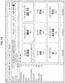
- FIG. 12illustrates a UI displaying group-based statistics and other information for the selected and grouped VM-type entities.
- the selected groupsare similar to the groups of entities created in the example of FIG. 10 .
- the UIdisplays attributes and metrics-based information about the combined set of entities in each group. For example, for the first group of Ubuntu VM-type entities, the UI displays the total number of hosts and VMs, the status of the VMs (e.g. active, suspended, or off), the amount of storage space being used, the current CPU usage for the group of entities, and memory usage.
- FIG. 13illustrates a UI displaying overall statistics and other information for all VM-type entities currently existing in the virtualization environment.
- the total number of VM-type entitiestotal disk capacity, total memory capacity, minimum, average, and maximum values for IOPs, bandwidth, and latency, etc.
- a usermay select one of the presented elements and view more information about the characteristic, or about the entity representing that value.
- the UImay switch the display to present information about the particular VM-type entity corresponding to that bandwidth.
- the UImay switch the display to present an individual breakdown of disk capacity by entity or by group.
- FIG. 14illustrates a UI displaying a graphical overview representation of current state and other information for host (machine) entities.
- a UImay display icons (e.g. a circle) for each of the hosts on which one or more VMs have been established, wherein the icons are sorted by power state.
- Each of the iconsmay further be colored or otherwise marked to indicate the corresponding entity's current power status, such as on, suspended, or off.
- the usermay select one or more entities simply by clicking on the corresponding icon, which may be marked with a check to indicate the selection.
- the usermay perform additional actions or apply labels to the selected entities.
- FIG. 15illustrates a UI displaying a graphical overview representation of current state and other information for a filtered subset of the VM-type entities currently existing in the virtualization environment. This may be similar to the example of FIG. 14 however the VM-type entities are no longer grouped by an attribute such as host machine.
- the iconsmay be differentiated in appearance to indicate that entity's current status. The user may select one or more entities by clicking on the corresponding icons, and perform additional actions or apply labels to the selected entities.
- the end usermay be faced with the problem of performing one or more operations on a large number of entities that are hosted in a remote/distributed environment.
- particular embodimentsmay provide a workflow or user interface that allows users to make a single request, which may be internally translated into localized requests that may then be performed on each of the individual nodes in the distributed environment.
- special logic in the frontendmay provide pre-validation feedback before given actions are made available to the user.
- a usermay want to power off three VMs of different cluster versions, but one of the three versions that the user has selected may not support a power-off action.
- the UImay have special logic to notify the user that such an action cannot be performed on one of those three selected VMs.
- the workflowmay enable the user to track the progress of their action in real time.
- particular embodimentsmay provide resiliency for the request from the central location by resuming the request from the point of failure should the central location go down.
- the workflowmay provide a sophisticated visualization of the progress of these tasks by automatically converging the progress of individual tasks into a parent task for easy perception.
- a task structuremay be as follows:
- usersmay be enabled to perform bulk operations in a vendor-agnostic, heterogeneous data center without tying the user to a particular hypervisor. In particular embodiments, this may simplify the data center operations with crash resistance and real time progress tracking.
- usersin addition to allowing the user to perform bulk actions from centralized location, users may be enabled to perform heterogeneous actions in the same action flow. As an example and not by way of limitation, the end user may make use of the user interface to both power on and power off thousands of VMs from a centralized location with a single request.
- the workflowmay use only one process thread throughout the process regardless the number of the target entities. Since most of the local jobs are expected done within 1 minute, the process is expected to complete within a short duration. In particular embodiments, the workflow may provide a five-minute maximum for all jobs to be done and synced back to the centralized location. In particular embodiments, if some jobs are not completed within five minutes, failure or error may be presumed, and so the process may be terminated in the centralized location, and the parent task may be marked as “failed” with a detailed reason attached.
- FIG. 16illustrates an example of range-based replication according to some embodiments.
- the replicacontained no changes, and then a change with the range [990 . . . 1000) is replicated.
- the replicamay apply the change and account for it in the replication state.
- the replication statecould be described by the map of the following ranges ⁇ 990, 1000 ⁇ .
- the replicacan apply the change and account for it in the replication state.
- the replication statecould be described by the map of the following ranges ⁇ 990, 1000 ⁇ , ⁇ 1100, 1110 ⁇ .
- the range based replication statecan represent replicated changes efficiently, and may be more precise than a “latest” timestamp value.
- Entities in the databasemay be linked in a hierarchical manner using “parent” links.
- An entitymay have any number of parents. For example, an entity with identifier “VM #3” could have a parent entity with identifier “Node #22,” in which case the “VM #3” entity would have a parent link pointing to “Node #22” entity.
- FIG. 17is a block diagram of an illustrative computing system 1700 suitable for implementing particular embodiments.
- one or more computer systems 1700may perform one or more steps of one or more methods described or illustrated herein.
- one or more computer systems 1700may provide functionality described or illustrated herein.
- software running on one or more computer systems 1700may perform one or more steps of one or more methods described or illustrated herein or provide functionality described or illustrated herein.
- Particular embodimentsinclude one or more portions of one or more computer systems 1700 .
- reference to a computer systemmay encompass a computing device, and vice versa, where appropriate.
- reference to a computer systemmay encompass one or more computer systems, where appropriate.
- computer system 1700may be an embedded computer system, a system-on-chip (SOC), a single-board computer system (SBC) (such as, for example, a computer-on-module (COM) or system-on-module (SOM)), a desktop computer system, a mainframe, a mesh of computer systems, a server, a laptop or notebook computer system, a tablet computer system, or a combination of two or more of these.
- SOCsystem-on-chip
- SBCsingle-board computer system
- COMcomputer-on-module
- SOMsystem-on-module
- computer system 1700may include one or more computer systems 1700 ; be unitary or distributed; span multiple locations; span multiple machines; span multiple data centers; or reside in a cloud, which may include one or more cloud components in one or more networks.
- one or more computer systems 1700may perform without substantial spatial or temporal limitation one or more steps of one or more methods described or illustrated herein.
- one or more computer systems 1700may perform in real time or in batch mode one or more steps of one or more methods described or illustrated herein.
- One or more computer systems 1700may perform at different times or at different locations one or more steps of one or more methods described or illustrated herein, where appropriate.
- Computer system 1700may include a bus 1706 (e.g., an address bus and a data bus) or other communication mechanism for communicating information, which interconnects subsystems and devices, such as processor 1707 , system memory 1708 (e.g., RAM), static storage device 1709 (e.g., ROM), disk drive 1710 (e.g., magnetic or optical), communication interface 1714 (e.g., modem, Ethernet card, a network interface controller (NIC) or network adapter for communicating with an Ethernet or other wire-based network, a wireless NIC (WNIC) or wireless adapter for communicating with a wireless network, such as a WI-FI network), display 1711 (e.g., CRT, LCD, LED), input device 1712 (e.g., keyboard, keypad, mouse, microphone).
- a bus 1706e.g., an address bus and a data bus
- other communication mechanism for communicating informationsuch as processor 1707 , system memory 1708 (e.g., RAM), static storage device 1709 (e.g.
- computer system 1700performs specific operations by processor 1707 executing one or more sequences of one or more instructions contained in system memory 1708 .
- Such instructionsmay be read into system memory 1708 from another computer readable/usable medium, such as static storage device 1709 or disk drive 1710 .
- static storage device 1709 or disk drive 1710may be used in place of or in combination with software instructions to implement the invention.
- hard-wired circuitrymay be used in place of or in combination with software instructions to implement the invention.
- embodimentsare not limited to any specific combination of hardware circuitry and/or software.
- the term “logic”shall mean any combination of software or hardware that is used to implement all or part of the invention.
- Non-volatile mediaincludes, for example, optical or magnetic disks, such as disk drive 1710 .
- Volatile mediaincludes dynamic memory, such as system memory 1708 .
- Computer readable mediainclude, for example, floppy disk, flexible disk, hard disk, magnetic tape, any other magnetic medium, CD-ROM, any other optical medium, punch cards, paper tape, any other physical medium with patterns of holes, RAM, PROM, EPROM, FLASH-EPROM, any other memory chip or cartridge, or any other medium from which a computer can read.
- execution of the sequences of instructions to practice the inventionis performed by a single computer system 1700 .
- two or more computer systems 1700 coupled by communication link 1715may perform the sequence of instructions required to practice the invention in coordination with one another.
- Computer system 1700may transmit and receive messages, data, and instructions, including program, i.e., application code, through communication link 1715 and communication interface 1714 .
- Received program codemay be executed by processor 1707 as it is received, and/or stored in disk drive 1710 , or other non-volatile storage for later execution.
- a database 1732 in a storage medium 1731may be used to store data accessible by the system 1700 by way of data interface 1733 .
- an apparatus or system or a component of an apparatus or systembeing adapted to, arranged to, capable of, configured to, enabled to, operable to, or operative to perform a particular function encompasses that apparatus, system, component, whether or not it or that particular function is activated, turned on, or unlocked, as long as that apparatus, system, or component is so adapted, arranged, capable, configured, enabled, operable, or operative.
Landscapes
- Engineering & Computer Science (AREA)
- Theoretical Computer Science (AREA)
- Databases & Information Systems (AREA)
- Physics & Mathematics (AREA)
- General Engineering & Computer Science (AREA)
- General Physics & Mathematics (AREA)
- Data Mining & Analysis (AREA)
- Software Systems (AREA)
- Computer Networks & Wireless Communication (AREA)
- Signal Processing (AREA)
- Quality & Reliability (AREA)
- Computational Linguistics (AREA)
- Computing Systems (AREA)
- Information Retrieval, Db Structures And Fs Structures Therefor (AREA)
Abstract
Description
- Point queries: retrieves an attribute value for a time range (e.g., fetch num_iops from VM1 for t1 to t2).
- Filter queries: retrieves entities or attributes based on filtering using expressions on entity attributes and statistics (e.g., fetch num_iops for VMs with cpu_usage>50).
- Grouping queries: retrieves entities or attributes grouped by entity attributes and statistics (e.g., fetch num_iops for all VMs grouped by cluster).
- Sorting queries: retrieves entities or attributes sorted by parameters
- Derived metrics: retrieves metrics based on expressions and rollup.
- for each attribute, an individual attribute rank may be a sum of the match closeness and the relevant attribute rank
- an entity attribute rank is calculated as the maximum of individual attribute ranks
- the relevance score may be calculated as the sum of entity attribute rank, related entity rank and context anchor entity rank.
- match closeness
- relevant attributes
- related entities
- contextual entities
- 1. entity id conversion,
- 2. attribute and metric addition/deletion/renaming,
- 3. conversion of attributes to metrics,
- 4. suppression of entity/attribute updates while still supporting addition of metric information, and
- 5. defining version-specific schema conversion.
| { |
| “status”: “kSucceeded”, |
| “internal_task”: false, |
| “cluster_uuid”: “27f1b89f-8b56-458b-a082-fa8bf6c51452”, |
| “internal_opaque”: “<bytes represent internal objects>”, |
| “logical_timestamp”: 6, |
| “deleted”: false, |
| “subtask_uuid_list”: [“4af3a50f-a353-47bf-92a1-89431d5c5dab”], |
| “component”: “kPrismCentral”, |
| “start_time_usecs”: 1455234405731588, |
| “percentage_complete”: 100, |
| “canceled”: false, |
| “sequence_id”: 7, |
| “last_updated_time_usecs”: 1455234408734287, |
| “create_time_usecs”: 1455234405635435, |
| “operation_type”: “kPrismFanout”, |
| “complete_time_usecs”: 1455234408734299, |
| “message”: “”, |
| “uuid”: “afbe1946-fcbe-45df-aa24-2b1693af8333” |
| } |
Claims (20)
Priority Applications (1)
| Application Number | Priority Date | Filing Date | Title |
|---|---|---|---|
| US15/423,477US11003476B2 (en) | 2016-02-12 | 2017-02-02 | Entity database historical data |
Applications Claiming Priority (2)
| Application Number | Priority Date | Filing Date | Title |
|---|---|---|---|
| US201662294980P | 2016-02-12 | 2016-02-12 | |
| US15/423,477US11003476B2 (en) | 2016-02-12 | 2017-02-02 | Entity database historical data |
Publications (2)
| Publication Number | Publication Date |
|---|---|
| US20170235772A1 US20170235772A1 (en) | 2017-08-17 |
| US11003476B2true US11003476B2 (en) | 2021-05-11 |
Family
ID=59559709
Family Applications (11)
| Application Number | Title | Priority Date | Filing Date |
|---|---|---|---|
| US15/423,470AbandonedUS20170235816A1 (en) | 2016-02-12 | 2017-02-02 | Entity database data aggregation |
| US15/423,478AbandonedUS20170235782A1 (en) | 2016-02-12 | 2017-02-02 | Entity database notifications |
| US15/423,494AbandonedUS20170235817A1 (en) | 2016-02-12 | 2017-02-02 | Entity database feedback aggregation |
| US15/423,476Active2037-05-29US10552192B2 (en) | 2016-02-12 | 2017-02-02 | Entity database timestamps |
| US15/423,472Active2038-01-25US10599459B2 (en) | 2016-02-12 | 2017-02-02 | Entity database distributed replication |
| US15/423,461Active2037-05-25US10223150B2 (en) | 2016-02-12 | 2017-02-02 | Entity database framework |
| US15/423,488AbandonedUS20170235737A1 (en) | 2016-02-12 | 2017-02-02 | Entity database ranking |
| US15/423,468Active2037-05-25US10489181B2 (en) | 2016-02-12 | 2017-02-02 | Entity database browser |
| US15/423,491Active2039-04-02US10956192B2 (en) | 2016-02-12 | 2017-02-02 | Entity database historical data |
| US15/423,482AbandonedUS20170235769A1 (en) | 2016-02-12 | 2017-02-02 | Entity database schemas |
| US15/423,477Active2039-02-23US11003476B2 (en) | 2016-02-12 | 2017-02-02 | Entity database historical data |
Family Applications Before (10)
| Application Number | Title | Priority Date | Filing Date |
|---|---|---|---|
| US15/423,470AbandonedUS20170235816A1 (en) | 2016-02-12 | 2017-02-02 | Entity database data aggregation |
| US15/423,478AbandonedUS20170235782A1 (en) | 2016-02-12 | 2017-02-02 | Entity database notifications |
| US15/423,494AbandonedUS20170235817A1 (en) | 2016-02-12 | 2017-02-02 | Entity database feedback aggregation |
| US15/423,476Active2037-05-29US10552192B2 (en) | 2016-02-12 | 2017-02-02 | Entity database timestamps |
| US15/423,472Active2038-01-25US10599459B2 (en) | 2016-02-12 | 2017-02-02 | Entity database distributed replication |
| US15/423,461Active2037-05-25US10223150B2 (en) | 2016-02-12 | 2017-02-02 | Entity database framework |
| US15/423,488AbandonedUS20170235737A1 (en) | 2016-02-12 | 2017-02-02 | Entity database ranking |
| US15/423,468Active2037-05-25US10489181B2 (en) | 2016-02-12 | 2017-02-02 | Entity database browser |
| US15/423,491Active2039-04-02US10956192B2 (en) | 2016-02-12 | 2017-02-02 | Entity database historical data |
| US15/423,482AbandonedUS20170235769A1 (en) | 2016-02-12 | 2017-02-02 | Entity database schemas |
Country Status (1)
| Country | Link |
|---|---|
| US (11) | US20170235816A1 (en) |
Families Citing this family (120)
| Publication number | Priority date | Publication date | Assignee | Title |
|---|---|---|---|---|
| US9411327B2 (en) | 2012-08-27 | 2016-08-09 | Johnson Controls Technology Company | Systems and methods for classifying data in building automation systems |
| US20140067869A1 (en) | 2012-08-30 | 2014-03-06 | Atheer, Inc. | Method and apparatus for content association and history tracking in virtual and augmented reality |
| US10476757B1 (en) | 2015-01-27 | 2019-11-12 | Nutanix, Inc. | Architecture for implementing centralized management for a computing environment |
| US10534326B2 (en) | 2015-10-21 | 2020-01-14 | Johnson Controls Technology Company | Building automation system with integrated building information model |
| US11268732B2 (en) | 2016-01-22 | 2022-03-08 | Johnson Controls Technology Company | Building energy management system with energy analytics |
| US11947785B2 (en) | 2016-01-22 | 2024-04-02 | Johnson Controls Technology Company | Building system with a building graph |
| US12196437B2 (en) | 2016-01-22 | 2025-01-14 | Tyco Fire & Security Gmbh | Systems and methods for monitoring and controlling an energy plant |
| AU2017214759B2 (en)* | 2016-02-01 | 2021-09-30 | Global Software Innovation Pty Ltd | Graph-based operations on an entity-relationship database |
| US20170235816A1 (en) | 2016-02-12 | 2017-08-17 | Nutanix, Inc. | Entity database data aggregation |
| US10235782B2 (en)* | 2016-03-14 | 2019-03-19 | International Business Machines Corporation | Increasing readability of visualization nodes |
| US11768004B2 (en) | 2016-03-31 | 2023-09-26 | Johnson Controls Tyco IP Holdings LLP | HVAC device registration in a distributed building management system |
| US10417451B2 (en) | 2017-09-27 | 2019-09-17 | Johnson Controls Technology Company | Building system with smart entity personal identifying information (PII) masking |
| US10505756B2 (en) | 2017-02-10 | 2019-12-10 | Johnson Controls Technology Company | Building management system with space graphs |
| US11774920B2 (en) | 2016-05-04 | 2023-10-03 | Johnson Controls Technology Company | Building system with user presentation composition based on building context |
| US9558265B1 (en)* | 2016-05-12 | 2017-01-31 | Quid, Inc. | Facilitating targeted analysis via graph generation based on an influencing parameter |
| US11218418B2 (en) | 2016-05-20 | 2022-01-04 | Nutanix, Inc. | Scalable leadership election in a multi-processing computing environment |
| EP3475820A4 (en)* | 2016-07-13 | 2019-06-26 | Huawei Technologies Co., Ltd. | ADAPTIVE RESOURCE MANAGEMENT IN DISTRIBUTED COMPUTING SYSTEMS |
| US10459939B1 (en) | 2016-07-31 | 2019-10-29 | Splunk Inc. | Parallel coordinates chart visualization for machine data search and analysis system |
| US10853380B1 (en) | 2016-07-31 | 2020-12-01 | Splunk Inc. | Framework for displaying interactive visualizations of event data |
| US10861202B1 (en) | 2016-07-31 | 2020-12-08 | Splunk Inc. | Sankey graph visualization for machine data search and analysis system |
| US10459938B1 (en) | 2016-07-31 | 2019-10-29 | Splunk Inc. | Punchcard chart visualization for machine data search and analysis system |
| US11037342B1 (en)* | 2016-07-31 | 2021-06-15 | Splunk Inc. | Visualization modules for use within a framework for displaying interactive visualizations of event data |
| CA3035277C (en) | 2016-09-02 | 2024-05-14 | FutureVault Inc. | Real-time document filtering systems and methods |
| US10684033B2 (en) | 2017-01-06 | 2020-06-16 | Johnson Controls Technology Company | HVAC system with automated device pairing |
| US11900287B2 (en) | 2017-05-25 | 2024-02-13 | Johnson Controls Tyco IP Holdings LLP | Model predictive maintenance system with budgetary constraints |
| US11994833B2 (en) | 2017-02-10 | 2024-05-28 | Johnson Controls Technology Company | Building smart entity system with agent based data ingestion and entity creation using time series data |
| US10417245B2 (en) | 2017-02-10 | 2019-09-17 | Johnson Controls Technology Company | Building management system with eventseries processing |
| US11360447B2 (en) | 2017-02-10 | 2022-06-14 | Johnson Controls Technology Company | Building smart entity system with agent based communication and control |
| US10452043B2 (en) | 2017-02-10 | 2019-10-22 | Johnson Controls Technology Company | Building management system with nested stream generation |
| US10854194B2 (en) | 2017-02-10 | 2020-12-01 | Johnson Controls Technology Company | Building system with digital twin based data ingestion and processing |
| US11280509B2 (en) | 2017-07-17 | 2022-03-22 | Johnson Controls Technology Company | Systems and methods for agent based building simulation for optimal control |
| US11307538B2 (en) | 2017-02-10 | 2022-04-19 | Johnson Controls Technology Company | Web services platform with cloud-eased feedback control |
| US10515098B2 (en)* | 2017-02-10 | 2019-12-24 | Johnson Controls Technology Company | Building management smart entity creation and maintenance using time series data |
| US12184444B2 (en) | 2017-02-10 | 2024-12-31 | Johnson Controls Technology Company | Space graph based dynamic control for buildings |
| US11764991B2 (en) | 2017-02-10 | 2023-09-19 | Johnson Controls Technology Company | Building management system with identity management |
| US11042144B2 (en) | 2017-03-24 | 2021-06-22 | Johnson Controls Technology Company | Building management system with dynamic channel communication |
| US11327737B2 (en) | 2017-04-21 | 2022-05-10 | Johnson Controls Tyco IP Holdings LLP | Building management system with cloud management of gateway configurations |
| US10788229B2 (en) | 2017-05-10 | 2020-09-29 | Johnson Controls Technology Company | Building management system with a distributed blockchain database |
| JP7184797B2 (en) | 2017-05-25 | 2022-12-06 | ジョンソン コントロールズ テクノロジー カンパニー | Model predictive maintenance system for building equipment |
| US11022947B2 (en) | 2017-06-07 | 2021-06-01 | Johnson Controls Technology Company | Building energy optimization system with economic load demand response (ELDR) optimization and ELDR user interfaces |
| US10496447B2 (en)* | 2017-06-08 | 2019-12-03 | Western Digital Technologies, Inc. | Partitioning nodes in a hyper-converged infrastructure |
| WO2018232147A1 (en) | 2017-06-15 | 2018-12-20 | Johnson Controls Technology Company | Building management system with artificial intelligence for unified agent based control of building subsystems |
| US10474508B2 (en)* | 2017-07-04 | 2019-11-12 | Vmware, Inc. | Replication management for hyper-converged infrastructures |
| CN108268580A (en)* | 2017-07-14 | 2018-07-10 | 广东神马搜索科技有限公司 | The answering method and device of knowledge based collection of illustrative plates |
| US11422516B2 (en) | 2017-07-21 | 2022-08-23 | Johnson Controls Tyco IP Holdings LLP | Building management system with dynamic rules with sub-rule reuse and equation driven smart diagnostics |
| US10648692B2 (en) | 2017-07-27 | 2020-05-12 | Johnson Controls Technology Company | Building management system with multi-dimensional analysis of building energy and equipment performance |
| US11120012B2 (en) | 2017-09-27 | 2021-09-14 | Johnson Controls Tyco IP Holdings LLP | Web services platform with integration and interface of smart entities with enterprise applications |
| US11314788B2 (en) | 2017-09-27 | 2022-04-26 | Johnson Controls Tyco IP Holdings LLP | Smart entity management for building management systems |
| US12339825B2 (en) | 2017-09-27 | 2025-06-24 | Tyco Fire & Security Gmbh | Building risk analysis system with risk cards |
| US10559180B2 (en) | 2017-09-27 | 2020-02-11 | Johnson Controls Technology Company | Building risk analysis system with dynamic modification of asset-threat weights |
| US10962945B2 (en) | 2017-09-27 | 2021-03-30 | Johnson Controls Technology Company | Building management system with integration of data into smart entities |
| CN109582433B (en)* | 2017-09-29 | 2022-02-01 | 腾讯科技(深圳)有限公司 | Resource scheduling method and device, cloud computing system and storage medium |
| CN107741875B (en)* | 2017-10-20 | 2020-08-21 | 北京易思捷信息技术有限公司 | Heterogeneous management system |
| US11281169B2 (en) | 2017-11-15 | 2022-03-22 | Johnson Controls Tyco IP Holdings LLP | Building management system with point virtualization for online meters |
| US10809682B2 (en) | 2017-11-15 | 2020-10-20 | Johnson Controls Technology Company | Building management system with optimized processing of building system data |
| US11127235B2 (en) | 2017-11-22 | 2021-09-21 | Johnson Controls Tyco IP Holdings LLP | Building campus with integrated smart environment |
| US10700991B2 (en) | 2017-11-27 | 2020-06-30 | Nutanix, Inc. | Multi-cluster resource management |
| US10776331B2 (en) | 2017-11-27 | 2020-09-15 | Red Hat, Inc. | Normalizing compound artifact dependency data |
| CN108256070B (en)* | 2018-01-17 | 2022-07-15 | 北京百度网讯科技有限公司 | Method and apparatus for generating information |
| CN108279880A (en)* | 2018-01-26 | 2018-07-13 | 长春玖佰软件技术有限公司 | A kind of configuration method of enterprise's application framework |
| EP3528186A1 (en)* | 2018-02-19 | 2019-08-21 | Siemens Aktiengesellschaft | Method and system of providing access to time-series data in a cloud computing environment |
| US11954713B2 (en) | 2018-03-13 | 2024-04-09 | Johnson Controls Tyco IP Holdings LLP | Variable refrigerant flow system with electricity consumption apportionment |
| US11294699B2 (en) | 2018-06-29 | 2022-04-05 | Hewlett Packard Enterprise Development Lp | Dynamically scaled hyperconverged system establishing minimum supported interoperable communication protocol between clusters in a cluster group |
| US10904330B2 (en)* | 2018-07-10 | 2021-01-26 | Vmware, Inc. | Systems, methods and apparatus to manage services in distributed systems |
| US20200073554A1 (en)* | 2018-09-05 | 2020-03-05 | International Business Machines Corporation | Applying Percentile Categories to Storage Volumes to Detect Behavioral Movement |
| CN111083309B (en)* | 2018-10-18 | 2022-04-01 | 北京魔门塔科技有限公司 | Time alignment method of multi-sensor data and data acquisition equipment |
| US11016648B2 (en) | 2018-10-30 | 2021-05-25 | Johnson Controls Technology Company | Systems and methods for entity visualization and management with an entity node editor |
| US11770447B2 (en) | 2018-10-31 | 2023-09-26 | Nutanix, Inc. | Managing high-availability file servers |
| US11927925B2 (en) | 2018-11-19 | 2024-03-12 | Johnson Controls Tyco IP Holdings LLP | Building system with a time correlated reliability data stream |
| CN109522498B (en)* | 2018-11-19 | 2021-06-22 | 中国船舶重工集团公司第七一六研究所 | Digital workshop heterogeneous terminal integrated display billboard method |
| US12367443B2 (en) | 2019-01-14 | 2025-07-22 | Tyco Fire & Security Gmbh | System and method for showing key performance indicators |
| US11769117B2 (en) | 2019-01-18 | 2023-09-26 | Johnson Controls Tyco IP Holdings LLP | Building automation system with fault analysis and component procurement |
| US10788798B2 (en) | 2019-01-28 | 2020-09-29 | Johnson Controls Technology Company | Building management system with hybrid edge-cloud processing |
| US11604786B2 (en)* | 2019-04-26 | 2023-03-14 | EMC IP Holding Company LLC | Method and system for processing unstable writes in a clustered file system |
| US10996975B2 (en) | 2019-08-22 | 2021-05-04 | Micron Technology, Inc. | Hierarchical memory systems |
| US12197299B2 (en) | 2019-12-20 | 2025-01-14 | Tyco Fire & Security Gmbh | Building system with ledger based software gateways |
| US11769066B2 (en) | 2021-11-17 | 2023-09-26 | Johnson Controls Tyco IP Holdings LLP | Building data platform with digital twin triggers and actions |
| US11894944B2 (en) | 2019-12-31 | 2024-02-06 | Johnson Controls Tyco IP Holdings LLP | Building data platform with an enrichment loop |
| US20210200713A1 (en) | 2019-12-31 | 2021-07-01 | Johnson Controls Technology Company | Systems and methods for generating a data structure from multiple bim files |
| US12231255B2 (en) | 2019-12-31 | 2025-02-18 | Tyco Fire & Security Gmbh | Building data platform with graph projections |
| US12021650B2 (en) | 2019-12-31 | 2024-06-25 | Tyco Fire & Security Gmbh | Building data platform with event subscriptions |
| US11442907B2 (en)* | 2020-02-03 | 2022-09-13 | Sap Se | Automatic conversion of data models using data model annotations |
| US12100280B2 (en) | 2020-02-04 | 2024-09-24 | Tyco Fire & Security Gmbh | Systems and methods for software defined fire detection and risk assessment |
| US11301450B2 (en)* | 2020-02-28 | 2022-04-12 | Netapp, Inc. | Maintaining timestamp parity of objects with alternate data streams during transition phase to synchronous state |
| US11537386B2 (en) | 2020-04-06 | 2022-12-27 | Johnson Controls Tyco IP Holdings LLP | Building system with dynamic configuration of network resources for 5G networks |
| US11768809B2 (en) | 2020-05-08 | 2023-09-26 | Nutanix, Inc. | Managing incremental snapshots for fast leader node bring-up |
| US11874809B2 (en) | 2020-06-08 | 2024-01-16 | Johnson Controls Tyco IP Holdings LLP | Building system with naming schema encoding entity type and entity relationships |
| CN111723296B (en)* | 2020-08-21 | 2020-12-15 | 浙江口碑网络技术有限公司 | Search processing method and device and computer equipment |
| JP7549254B2 (en) | 2020-09-14 | 2024-09-11 | 日本電信電話株式会社 | Information processing system, connection control method and program |
| JP7549253B2 (en)* | 2020-09-14 | 2024-09-11 | 日本電信電話株式会社 | Information processing system, information processing method, and program |
| US11568862B2 (en)* | 2020-09-29 | 2023-01-31 | Cisco Technology, Inc. | Natural language understanding model with context resolver |
| US12346381B2 (en) | 2020-09-30 | 2025-07-01 | Tyco Fire & Security Gmbh | Building management system with semantic model integration |
| US11397773B2 (en) | 2020-09-30 | 2022-07-26 | Johnson Controls Tyco IP Holdings LLP | Building management system with semantic model integration |
| US11954154B2 (en) | 2020-09-30 | 2024-04-09 | Johnson Controls Tyco IP Holdings LLP | Building management system with semantic model integration |
| US12231496B2 (en) | 2020-10-30 | 2025-02-18 | Tyco Fire & Security Gmbh | Building management system with dynamic building model enhanced by digital twins |
| US12061453B2 (en) | 2020-12-18 | 2024-08-13 | Tyco Fire & Security Gmbh | Building management system performance index |
| PT116969A (en)* | 2020-12-23 | 2022-06-23 | Altice Labs S A | GENERATION OF A COMPUTER PLAN OF MAIN PERFORMANCE INDICATORS |
| US12235617B2 (en) | 2021-02-08 | 2025-02-25 | Tyco Fire & Security Gmbh | Site command and control tool with dynamic model viewer |
| WO2022197964A1 (en) | 2021-03-17 | 2022-09-22 | Johnson Controls Tyco IP Holdings LLP | Systems and methods for determining equipment energy waste |
| CN112948063B (en)* | 2021-05-17 | 2021-09-17 | 北京汇钧科技有限公司 | Cloud platform creation method and device, cloud platform and cloud platform implementation system |
| US11899723B2 (en) | 2021-06-22 | 2024-02-13 | Johnson Controls Tyco IP Holdings LLP | Building data platform with context based twin function processing |
| US12210831B2 (en)* | 2021-08-27 | 2025-01-28 | Microsoft Technology Licensing, Llc. | Knowledge base with type discovery |
| US20230067688A1 (en)* | 2021-08-27 | 2023-03-02 | Microsoft Technology Licensing, Llc | Knowledge base with type discovery |
| US11796974B2 (en) | 2021-11-16 | 2023-10-24 | Johnson Controls Tyco IP Holdings LLP | Building data platform with schema extensibility for properties and tags of a digital twin |
| US11934966B2 (en) | 2021-11-17 | 2024-03-19 | Johnson Controls Tyco IP Holdings LLP | Building data platform with digital twin inferences |
| US12399467B2 (en) | 2021-11-17 | 2025-08-26 | Tyco Fire & Security Gmbh | Building management systems and methods for tuning fault detection thresholds |
| US11704311B2 (en) | 2021-11-24 | 2023-07-18 | Johnson Controls Tyco IP Holdings LLP | Building data platform with a distributed digital twin |
| US12412003B2 (en) | 2021-11-29 | 2025-09-09 | Tyco Fire & Security Gmbh | Building data platform with digital twin based predictive recommendation visualization |
| US12013673B2 (en) | 2021-11-29 | 2024-06-18 | Tyco Fire & Security Gmbh | Building control system using reinforcement learning |
| US11714930B2 (en) | 2021-11-29 | 2023-08-01 | Johnson Controls Tyco IP Holdings LLP | Building data platform with digital twin based inferences and predictions for a graphical building model |
| US12333657B2 (en) | 2021-12-01 | 2025-06-17 | Tyco Fire & Security Gmbh | Building data platform with augmented reality based digital twins |
| CN114866306B (en)* | 2022-04-24 | 2022-12-23 | 北京丁牛科技有限公司 | Safety protection method, device and storage medium |
| US12229112B2 (en)* | 2022-04-28 | 2025-02-18 | Sap Se | Efficiently managing changes to master data |
| US12372955B2 (en) | 2022-05-05 | 2025-07-29 | Tyco Fire & Security Gmbh | Building data platform with digital twin functionality indicators |
| US11947551B2 (en)* | 2022-05-27 | 2024-04-02 | Maplebear Inc. | Automated sampling of query results for training of a query engine |
| US12013823B2 (en) | 2022-09-08 | 2024-06-18 | Tyco Fire & Security Gmbh | Gateway system that maps points into a graph schema |
| US12061633B2 (en) | 2022-09-08 | 2024-08-13 | Tyco Fire & Security Gmbh | Building system that maps points into a graph schema |
| US20240311339A1 (en)* | 2023-03-13 | 2024-09-19 | Open Text Holdings, Inc. | Dynamic clustering based on attribute relationships |
| US12360832B2 (en)* | 2023-09-22 | 2025-07-15 | DexCare, Inc. | Entity relationships and versioning |
| US20250150343A1 (en)* | 2023-11-08 | 2025-05-08 | Arista Networks, Inc. | Unified Network Entity |
Citations (127)
| Publication number | Priority date | Publication date | Assignee | Title |
|---|---|---|---|---|
| US6011537A (en) | 1997-01-27 | 2000-01-04 | Slotznick; Benjamin | System for delivering and simultaneously displaying primary and secondary information, and for displaying only the secondary information during interstitial space |
| US6031533A (en) | 1996-07-03 | 2000-02-29 | Sun Microsystems, Inc. | Graphical user interface for use in a de-centralized network environment |
| US6098157A (en) | 1998-04-24 | 2000-08-01 | Shomiti Systems, Inc. | Method for storing and updating information describing data traffic on a network |
| US20020054152A1 (en) | 1999-08-23 | 2002-05-09 | Murugan Palaniappan | Menu infrastructure apparatus and method |
| US20020129136A1 (en) | 2001-03-08 | 2002-09-12 | Matharu Tarlochan S. | System and method for wap server management using a single console |
| US20030058277A1 (en) | 1999-08-31 | 2003-03-27 | Bowman-Amuah Michel K. | A view configurer in a presentation services patterns enviroment |
| US20030110262A1 (en) | 2001-07-06 | 2003-06-12 | Taqi Hasan | Integrated rule network management system |
| US20030120710A1 (en) | 2001-12-20 | 2003-06-26 | Darren Pulsipher | Hierarchically structured logging for computer work processing |
| US20040177090A1 (en) | 2003-02-27 | 2004-09-09 | Timothy Corbett-Clark | Database system |
| US20040215430A1 (en) | 2002-04-19 | 2004-10-28 | Huddleston David Eugene | Method and apparatus for discovering evolutionary changes within a system |
| US20050149501A1 (en) | 2004-01-05 | 2005-07-07 | Barrett Peter T. | Configuration of user interfaces |
| US20050283753A1 (en) | 2003-08-07 | 2005-12-22 | Denise Ho | Alert triggers and event management in a relationship system |
| US20050287353A1 (en) | 2004-06-24 | 2005-12-29 | Trogolo Jeffrey A | Antimicrobial coating for erosive environments |
| US20060010101A1 (en) | 2004-07-08 | 2006-01-12 | Yasuhiro Suzuki | System, method and program product for forecasting the demand on computer resources |
| US20060067252A1 (en) | 2004-09-30 | 2006-03-30 | Ajita John | Method and apparatus for providing communication tasks in a workflow |
| US20060259592A1 (en) | 2005-05-10 | 2006-11-16 | Angeline Brent J | Internet operating system |
| US20070043550A1 (en) | 2005-08-16 | 2007-02-22 | Tzruya Yoav M | System and method for providing a remote user interface for an application executing on a computing device |
| US20070106748A1 (en) | 2005-11-01 | 2007-05-10 | Jakobsson Bjorn M | Method and apparatus for storing information in a browser storage area of a client device |
| US20080015823A1 (en) | 2006-06-16 | 2008-01-17 | Tectonic Network, Inc. | Extensible building information model toolset |
| US20080040661A1 (en) | 2006-07-07 | 2008-02-14 | Bryce Allen Curtis | Method for inheriting a Wiki page layout for a Wiki page |
| US20080091800A1 (en) | 2006-10-13 | 2008-04-17 | Xerox Corporation | Local user interface support of remote services |
| US20080126856A1 (en) | 2006-08-18 | 2008-05-29 | Microsoft Corporation | Configuration replication for system recovery and migration |
| US20080177839A1 (en) | 2007-01-24 | 2008-07-24 | Chia Hao Chang | Method, System, and Program for Integrating Disjoined but Related Network Components into Collaborative Communities |
| US20090019436A1 (en) | 2007-04-05 | 2009-01-15 | George Hartz | Augmenting a Virtual Machine Hosting Environment from within a Virtual Machine |
| US20090077623A1 (en) | 2005-03-16 | 2009-03-19 | Marc Baum | Security Network Integrating Security System and Network Devices |
| US20090150851A1 (en) | 2007-12-07 | 2009-06-11 | Martijn De Boer | Developing Java Server Components Without Restarting the Application Server |
| US20090177998A1 (en) | 2008-01-09 | 2009-07-09 | Barrios Daiv S | Method and System for Efficiently Adjusting a Timeline in a Time Window |
| US20090241104A1 (en) | 2008-03-20 | 2009-09-24 | Microsoft Corporation | Application management within deployable object hierarchy |
| US20090282333A1 (en) | 2008-05-08 | 2009-11-12 | Dialogic Corporation | System and method to permit language independence for web interfaces |
| US20090288084A1 (en)* | 2008-05-02 | 2009-11-19 | Skytap | Multitenant hosted virtual machine infrastructure |
| US20100077362A1 (en) | 2008-04-22 | 2010-03-25 | Medio Systems, Inc. | Server-controlled user interface |
| US7693753B1 (en) | 2002-01-31 | 2010-04-06 | Karen Purdy | System and method for presenting items and obtaining user selections of those items |
| US7725671B2 (en) | 2005-11-28 | 2010-05-25 | Comm Vault Systems, Inc. | System and method for providing redundant access to metadata over a network |
| US20100131264A1 (en) | 2008-11-21 | 2010-05-27 | At&T Intellectual Property I, L.P. | System and method for handling missing speech data |
| US7809833B2 (en) | 2008-07-15 | 2010-10-05 | International Business Machines Corporation | Asymmetric dynamic server clustering with inter-cluster workload balancing |
| US20100269152A1 (en) | 2009-04-15 | 2010-10-21 | Wyse Technology Inc. | Method and system for rendering composite view of an application |
| US7840533B2 (en) | 2003-11-13 | 2010-11-23 | Commvault Systems, Inc. | System and method for performing an image level snapshot and for restoring partial volume data |
| US20110023031A1 (en) | 2008-08-22 | 2011-01-27 | Bonola Thomas J | Server virtualized using virtualization platform |
| US20110035802A1 (en) | 2009-08-07 | 2011-02-10 | Microsoft Corporation | Representing virtual object priority based on relationships |
| US20110087874A1 (en) | 2009-10-12 | 2011-04-14 | Veeam Software International Ltd. | Item-level restoration and verification of image level backups |
| US20110154338A1 (en) | 2009-12-23 | 2011-06-23 | Oracle International Corporation | Task management using electronic mail |
| US20110209047A1 (en) | 2008-05-08 | 2011-08-25 | Olsen Ronald D | System and method to permit language independence for web interfaces |
| US20110238817A1 (en) | 2010-03-25 | 2011-09-29 | Hitachi, Ltd. | Network Monitoring Server And Network Monitoring System |
| US20110252117A1 (en) | 2010-04-12 | 2011-10-13 | Swee Huat Sng | Devices and Methods for Redirecting a Browser to Access Computer Resource Behind a Network Firewall |
| US20110277027A1 (en) | 2010-05-07 | 2011-11-10 | Richard Hayton | Systems and Methods for Providing a Single Click Access to Enterprise, SAAS and Cloud Hosted Application |
| US20120011509A1 (en) | 2007-02-15 | 2012-01-12 | Syed Mohammad Amir Husain | Migrating Session State of a Machine Without Using Memory Images |
| US20120047130A1 (en) | 2010-08-20 | 2012-02-23 | Sap Ag | UI Driven Service Composition Tool with UI Designer Feedback |
| US20120054265A1 (en) | 2010-09-01 | 2012-03-01 | Kazerani Alexander A | Optimized Content Distribution Based on Metrics Derived from the End User |
| US20120092277A1 (en) | 2010-10-05 | 2012-04-19 | Citrix Systems, Inc. | Touch Support for Remoted Applications |
| US20120117497A1 (en) | 2010-11-08 | 2012-05-10 | Nokia Corporation | Method and apparatus for applying changes to a user interface |
| US20120124593A1 (en)* | 2008-09-19 | 2012-05-17 | Jason John Walsh | Process development system |
| US20120144391A1 (en) | 2010-12-02 | 2012-06-07 | International Business Machines Corporation | Provisioning a virtual machine |
| US20120163206A1 (en) | 2010-08-24 | 2012-06-28 | Kenneth Man-Kin Leung | Method and apparatus for analysis of user traffic within a predefined area |
| US20120284713A1 (en) | 2008-02-13 | 2012-11-08 | Quest Software, Inc. | Systems and methods for analyzing performance of virtual environments |
| US20120297179A1 (en) | 2011-04-28 | 2012-11-22 | Mikael Lirbank | Methods, devices, and systems for establishing, setting-up, and maintaining a virtual computer infrastructure |
| US20120317491A1 (en) | 2011-06-07 | 2012-12-13 | Vmware, Inc. | Network connectivity and security visualization |
| US20130031094A1 (en)* | 2011-07-28 | 2013-01-31 | Google Inc. | Clustering of feedback reports |
| US20130055092A1 (en) | 2011-08-25 | 2013-02-28 | Vmware, Inc. | User interface for networks including virtual machines |
| US20130055247A1 (en) | 2011-08-26 | 2013-02-28 | Vmware, Inc. | Management of software updates in a datacenter |
| US20130117359A1 (en) | 2007-02-15 | 2013-05-09 | Clearcube Technology, Inc. | Capturing and Restoring Session State of a Machine Without Using Memory Images |
| US8447728B2 (en) | 2006-10-17 | 2013-05-21 | Commvault Systems, Inc. | System and method for storage operation access security |
| US20130198133A1 (en) | 2012-01-31 | 2013-08-01 | Altibase Corp. | Parallel processing apparatus and method in database management system for synchronous replication |
| US20130247133A1 (en) | 2011-10-13 | 2013-09-19 | Mcafee, Inc. | Security assessment of virtual machine environments |
| US8549518B1 (en) | 2011-08-10 | 2013-10-01 | Nutanix, Inc. | Method and system for implementing a maintenanece service for managing I/O and storage for virtualization environment |
| US20130307854A1 (en) | 2010-11-08 | 2013-11-21 | Broy Hannah Karin Nora | Method and System for Visualising a System Model |
| US8601473B1 (en) | 2011-08-10 | 2013-12-03 | Nutanix, Inc. | Architecture for managing I/O and storage for a virtualization environment |
| US8621569B1 (en) | 2009-04-01 | 2013-12-31 | Netapp Inc. | Intercluster relationship management |
| US20140020083A1 (en) | 2006-05-17 | 2014-01-16 | Richard Fetik | Customizable Storage Controller With Integrated F+ Storage Firewall Protection |
| US8634330B2 (en) | 2011-04-04 | 2014-01-21 | International Business Machines Corporation | Inter-cluster communications technique for event and health status communications |
| US8671176B1 (en) | 2011-04-29 | 2014-03-11 | Juniper Networks, Inc. | Virtual network prototyping environment |
| US20140115250A1 (en) | 2007-08-30 | 2014-04-24 | Commvault Systems, Inc. | Parallel access virtual tape library and drives |
| US20140149793A1 (en) | 2012-11-27 | 2014-05-29 | Red Hat Israel, Ltd. | Database change compensation after a transaction commit |
| US20140172803A1 (en) | 2012-12-19 | 2014-06-19 | Microsoft Corporation | Main-memory database checkpointing |
| US20140189685A1 (en) | 2012-12-28 | 2014-07-03 | Commvault Systems, Inc. | Systems and methods for repurposing virtual machines |
| US20140188899A1 (en) | 2012-12-31 | 2014-07-03 | Thomas S. Whitnah | Modifying Structured Search Queries on Online Social Networks |
| US20140215279A1 (en) | 2013-01-30 | 2014-07-31 | Hewlett-Packard Development Company, L.P. | Scalable structured data store operations |
| US20140214922A1 (en) | 2013-01-31 | 2014-07-31 | Electronics And Telecommunications Research Institute | Method of providing virtual machine and service gateway for real-time virtual desktop service |
| US20140282543A1 (en) | 2013-03-15 | 2014-09-18 | Ologn Technologies Ag | Secure zone on a virutal machine for digital communications |
| US8850130B1 (en) | 2011-08-10 | 2014-09-30 | Nutanix, Inc. | Metadata for managing I/O and storage for a virtualization |
| US20140304407A1 (en) | 2012-12-21 | 2014-10-09 | Boundary, Inc. | Visualizing Ephemeral Traffic |
| US20140304713A1 (en) | 2011-11-23 | 2014-10-09 | Telefonaktiebolaget L M Ericsson (pulb) | Method and apparatus for distributed processing tasks |
| US8863124B1 (en) | 2011-08-10 | 2014-10-14 | Nutanix, Inc. | Architecture for managing I/O and storage for a virtualization environment |
| US20140325036A1 (en) | 2013-04-29 | 2014-10-30 | Telefonaktiebolaget L M Ericsson (Publ) | Defining Disjoint Node Groups for Virtual Machines with Pre-Existing Placement Policies |
| US20140337834A1 (en) | 2013-05-08 | 2014-11-13 | Amazon Technologies, Inc. | User-Influenced Placement of Virtual Machine Instances |
| US20140365531A1 (en) | 2013-06-07 | 2014-12-11 | Vmware,Inc. | Creation of a graph database of a virtualization infrastructure |
| US8935248B2 (en)* | 2010-05-17 | 2015-01-13 | United States Postal Service | Localized data affinity system and hybrid method |
| US20150082179A1 (en) | 2013-09-13 | 2015-03-19 | American Megatrends, Inc. | Monitoring virtual machine interface and local graphical user interface on a thin client and alternating therebetween |
| US9003141B2 (en) | 2011-11-14 | 2015-04-07 | Ca, Inc. | Enhanced software application platform |
| US20150113528A1 (en) | 2013-10-21 | 2015-04-23 | Electronics And Telecommunications Research Institute | Virtual desktop service apparatus and method |
| US20150121369A1 (en) | 2013-10-31 | 2015-04-30 | Vmware, Inc. | Guarded virtual machines |
| US20150127807A1 (en) | 2013-11-07 | 2015-05-07 | International Business Machines Corporation | Modeling computer network topology based on dynamic usage relationships |
| US20150135255A1 (en)* | 2013-11-11 | 2015-05-14 | Amazon Technologies, Inc. | Client-configurable security options for data streams |
| US20150163206A1 (en) | 2013-12-11 | 2015-06-11 | Intralinks, Inc. | Customizable secure data exchange environment |
| US20150220080A1 (en) | 2014-01-31 | 2015-08-06 | Fisher-Rosemount Systems, Inc. | Managing Big Data In Process Control Systems |
| US20150256475A1 (en) | 2014-03-05 | 2015-09-10 | Wipro Limited | Systems and methods for designing an optimized infrastructure forexecuting computing processes |
| US9134992B2 (en) | 2011-08-31 | 2015-09-15 | Vmware, Inc. | Interactive and visual planning tool for managing installs and upgrades |
| US20150295992A1 (en) | 2013-10-16 | 2015-10-15 | Empire Technology Development Llc | Control redistribution among multiple devices |
| US20150297776A1 (en) | 2014-04-18 | 2015-10-22 | Thomas A. Conroy | Method and system of a network of diffusers including a liquid level sensor |
| US9189284B2 (en) | 2008-12-31 | 2015-11-17 | Dell Products L.P. | Systems and methods for managing computing resources within a network |
| US20150350446A1 (en) | 2014-05-29 | 2015-12-03 | CafeX Communications, Ltd. | Load balancing and sharing of contextual information in a multi-vendor and/or multiple contact center environment |
| US20150356773A1 (en) | 2014-06-09 | 2015-12-10 | Citrix Systems, Inc. | Systems and methods for providing virtual monitors |
| US20150363190A1 (en) | 2014-06-11 | 2015-12-17 | Microsoft Corporation | Dynamic pacing for service upgrades |
| US9231988B2 (en) | 2011-03-08 | 2016-01-05 | Rackspace Us, Inc. | Intercluster repository synchronizer and method of synchronizing objects using a synchronization indicator and shared metadata |
| US9239820B1 (en) | 2014-01-08 | 2016-01-19 | Workiva Inc. | Method and apparatus for selective visual formatting of an electronic document using a style element lock status |
| US9268590B2 (en) | 2012-02-29 | 2016-02-23 | Vmware, Inc. | Provisioning a cluster of distributed computing platform based on placement strategy |
| US20160062789A1 (en) | 2006-12-21 | 2016-03-03 | Vmware, Inc. | Storage architecture for virtual machines |
| US9317452B1 (en) | 2013-11-18 | 2016-04-19 | Amazon Technologies, Inc. | Selective restrictions to memory mapped registers using an emulator |
| US20160179566A1 (en) | 2010-01-27 | 2016-06-23 | Vmware, Inc. | Independent access to virtual machine desktop content |
| US9407572B2 (en) | 2008-11-26 | 2016-08-02 | Red Hat, Inc. | Multiple cloud marketplace aggregation |
| US9420004B2 (en) | 2013-11-27 | 2016-08-16 | Vmware, Inc. | Dynamic expression evaluation based grouping of VM objects for networking and security services in a virtualized computing system |
| US9424545B1 (en) | 2015-01-15 | 2016-08-23 | Hito Management Company | Geospatial construction task management system and method |
| US20160261564A1 (en) | 2014-06-20 | 2016-09-08 | Zscaler, Inc. | Cloud-based virtual private access systems and methods |
| US20160337426A1 (en) | 2015-05-14 | 2016-11-17 | Hola Networks Ltd. | System and Method for Streaming Content from Multiple Servers |
| US20160359680A1 (en) | 2015-06-05 | 2016-12-08 | Cisco Technology, Inc. | Cluster discovery via multi-domain fusion for application dependency mapping |
| US20160378554A1 (en) | 2015-06-29 | 2016-12-29 | Vmware, Inc. | Parallel and Distributed Computing Using Multiple Virtual Machines |
| US20170109217A1 (en) | 2015-10-16 | 2017-04-20 | Qualcomm Incorporated | Method For Efficient Task Scheduling In The Presence Of Conflicts |
| US20170139997A1 (en) | 2015-11-18 | 2017-05-18 | American Express Travel Related Services Company, | System and method for reading and writing to big data storage formats |
| US20170208138A1 (en) | 2016-01-20 | 2017-07-20 | Bluedata Software, Inc. | Allocating edge services with large-scale processing framework clusters |
| US20170235817A1 (en) | 2016-02-12 | 2017-08-17 | Nutanix, Inc. | Entity database feedback aggregation |
| US9740723B2 (en) | 2008-09-05 | 2017-08-22 | Commvault Systems, Inc. | Systems and methods for management of virtualization data |
| US9767197B1 (en) | 2014-08-20 | 2017-09-19 | Vmware, Inc. | Datacenter operations using search and analytics |
| US9772866B1 (en) | 2012-07-17 | 2017-09-26 | Nutanix, Inc. | Architecture for implementing a virtualization environment and appliance |
| US20170299645A1 (en) | 2014-12-31 | 2017-10-19 | Huawei Technologies Co., Ltd. | Fault Analysis Method and Apparatus Based on Data Center |
| US10210048B2 (en) | 2016-10-25 | 2019-02-19 | Commvault Systems, Inc. | Selective snapshot and backup copy operations for individual virtual machines in a shared storage |
| US10248657B2 (en) | 2009-06-30 | 2019-04-02 | Commvault Systems, Inc. | Data object store and server for a cloud storage environment, including data deduplication and data management across multiple cloud storage sites |
| US10248618B1 (en) | 2014-03-31 | 2019-04-02 | EMC IP Holding Company LLC | Scheduling snapshots |
| US20190349254A1 (en) | 2016-12-30 | 2019-11-14 | Intel Corporation | Service Provision To IoT Devices |
Family Cites Families (5)
| Publication number | Priority date | Publication date | Assignee | Title |
|---|---|---|---|---|
| US7386662B1 (en)* | 2005-06-20 | 2008-06-10 | Symantec Operating Corporation | Coordination of caching and I/O management in a multi-layer virtualized storage environment |
| US8595262B1 (en) | 2012-03-29 | 2013-11-26 | Amazon Technologies, Inc. | Resource resolution in computing environments using directed graphs |
| US9326820B2 (en)* | 2012-07-10 | 2016-05-03 | Regear Life Sciences Inc. | Diathermy applicator garment |
| US10853335B2 (en)* | 2016-01-11 | 2020-12-01 | Facebook, Inc. | Identification of real-best-pages on online social networks |
| US20190334778A1 (en) | 2016-11-30 | 2019-10-31 | Nutanix, Inc. | Generic access to heterogeneous virtualized entities |
- 2017
- 2017-02-02USUS15/423,470patent/US20170235816A1/ennot_activeAbandoned
- 2017-02-02USUS15/423,478patent/US20170235782A1/ennot_activeAbandoned
- 2017-02-02USUS15/423,494patent/US20170235817A1/ennot_activeAbandoned
- 2017-02-02USUS15/423,476patent/US10552192B2/enactiveActive
- 2017-02-02USUS15/423,472patent/US10599459B2/enactiveActive
- 2017-02-02USUS15/423,461patent/US10223150B2/enactiveActive
- 2017-02-02USUS15/423,488patent/US20170235737A1/ennot_activeAbandoned
- 2017-02-02USUS15/423,468patent/US10489181B2/enactiveActive
- 2017-02-02USUS15/423,491patent/US10956192B2/enactiveActive
- 2017-02-02USUS15/423,482patent/US20170235769A1/ennot_activeAbandoned
- 2017-02-02USUS15/423,477patent/US11003476B2/enactiveActive
Patent Citations (129)
| Publication number | Priority date | Publication date | Assignee | Title |
|---|---|---|---|---|
| US6031533A (en) | 1996-07-03 | 2000-02-29 | Sun Microsystems, Inc. | Graphical user interface for use in a de-centralized network environment |
| US6011537A (en) | 1997-01-27 | 2000-01-04 | Slotznick; Benjamin | System for delivering and simultaneously displaying primary and secondary information, and for displaying only the secondary information during interstitial space |
| US6098157A (en) | 1998-04-24 | 2000-08-01 | Shomiti Systems, Inc. | Method for storing and updating information describing data traffic on a network |
| US20020054152A1 (en) | 1999-08-23 | 2002-05-09 | Murugan Palaniappan | Menu infrastructure apparatus and method |
| US20030058277A1 (en) | 1999-08-31 | 2003-03-27 | Bowman-Amuah Michel K. | A view configurer in a presentation services patterns enviroment |
| US20020129136A1 (en) | 2001-03-08 | 2002-09-12 | Matharu Tarlochan S. | System and method for wap server management using a single console |
| US20030110262A1 (en) | 2001-07-06 | 2003-06-12 | Taqi Hasan | Integrated rule network management system |
| US20030120710A1 (en) | 2001-12-20 | 2003-06-26 | Darren Pulsipher | Hierarchically structured logging for computer work processing |
| US7693753B1 (en) | 2002-01-31 | 2010-04-06 | Karen Purdy | System and method for presenting items and obtaining user selections of those items |
| US20040215430A1 (en) | 2002-04-19 | 2004-10-28 | Huddleston David Eugene | Method and apparatus for discovering evolutionary changes within a system |
| US20040177090A1 (en) | 2003-02-27 | 2004-09-09 | Timothy Corbett-Clark | Database system |
| US20050283753A1 (en) | 2003-08-07 | 2005-12-22 | Denise Ho | Alert triggers and event management in a relationship system |
| US7840533B2 (en) | 2003-11-13 | 2010-11-23 | Commvault Systems, Inc. | System and method for performing an image level snapshot and for restoring partial volume data |
| US20050149501A1 (en) | 2004-01-05 | 2005-07-07 | Barrett Peter T. | Configuration of user interfaces |
| US20050287353A1 (en) | 2004-06-24 | 2005-12-29 | Trogolo Jeffrey A | Antimicrobial coating for erosive environments |
| US20060010101A1 (en) | 2004-07-08 | 2006-01-12 | Yasuhiro Suzuki | System, method and program product for forecasting the demand on computer resources |
| US20060067252A1 (en) | 2004-09-30 | 2006-03-30 | Ajita John | Method and apparatus for providing communication tasks in a workflow |
| US20090077623A1 (en) | 2005-03-16 | 2009-03-19 | Marc Baum | Security Network Integrating Security System and Network Devices |
| US20060259592A1 (en) | 2005-05-10 | 2006-11-16 | Angeline Brent J | Internet operating system |
| US20070043550A1 (en) | 2005-08-16 | 2007-02-22 | Tzruya Yoav M | System and method for providing a remote user interface for an application executing on a computing device |
| US20070106748A1 (en) | 2005-11-01 | 2007-05-10 | Jakobsson Bjorn M | Method and apparatus for storing information in a browser storage area of a client device |
| US7725671B2 (en) | 2005-11-28 | 2010-05-25 | Comm Vault Systems, Inc. | System and method for providing redundant access to metadata over a network |
| US20140020083A1 (en) | 2006-05-17 | 2014-01-16 | Richard Fetik | Customizable Storage Controller With Integrated F+ Storage Firewall Protection |
| US20080015823A1 (en) | 2006-06-16 | 2008-01-17 | Tectonic Network, Inc. | Extensible building information model toolset |
| US20080040661A1 (en) | 2006-07-07 | 2008-02-14 | Bryce Allen Curtis | Method for inheriting a Wiki page layout for a Wiki page |
| US20080126856A1 (en) | 2006-08-18 | 2008-05-29 | Microsoft Corporation | Configuration replication for system recovery and migration |
| US20080091800A1 (en) | 2006-10-13 | 2008-04-17 | Xerox Corporation | Local user interface support of remote services |
| US8762335B2 (en) | 2006-10-17 | 2014-06-24 | Commvault Systems, Inc. | System and method for storage operation access security |
| US8447728B2 (en) | 2006-10-17 | 2013-05-21 | Commvault Systems, Inc. | System and method for storage operation access security |
| US20160062789A1 (en) | 2006-12-21 | 2016-03-03 | Vmware, Inc. | Storage architecture for virtual machines |
| US20080177839A1 (en) | 2007-01-24 | 2008-07-24 | Chia Hao Chang | Method, System, and Program for Integrating Disjoined but Related Network Components into Collaborative Communities |
| US20130117359A1 (en) | 2007-02-15 | 2013-05-09 | Clearcube Technology, Inc. | Capturing and Restoring Session State of a Machine Without Using Memory Images |
| US20120011509A1 (en) | 2007-02-15 | 2012-01-12 | Syed Mohammad Amir Husain | Migrating Session State of a Machine Without Using Memory Images |
| US20090019436A1 (en) | 2007-04-05 | 2009-01-15 | George Hartz | Augmenting a Virtual Machine Hosting Environment from within a Virtual Machine |
| US20140115250A1 (en) | 2007-08-30 | 2014-04-24 | Commvault Systems, Inc. | Parallel access virtual tape library and drives |
| US20090150851A1 (en) | 2007-12-07 | 2009-06-11 | Martijn De Boer | Developing Java Server Components Without Restarting the Application Server |
| US20090177998A1 (en) | 2008-01-09 | 2009-07-09 | Barrios Daiv S | Method and System for Efficiently Adjusting a Timeline in a Time Window |
| US20120284713A1 (en) | 2008-02-13 | 2012-11-08 | Quest Software, Inc. | Systems and methods for analyzing performance of virtual environments |
| US20090241104A1 (en) | 2008-03-20 | 2009-09-24 | Microsoft Corporation | Application management within deployable object hierarchy |
| US20100077362A1 (en) | 2008-04-22 | 2010-03-25 | Medio Systems, Inc. | Server-controlled user interface |
| US20090288084A1 (en)* | 2008-05-02 | 2009-11-19 | Skytap | Multitenant hosted virtual machine infrastructure |
| US20090282333A1 (en) | 2008-05-08 | 2009-11-12 | Dialogic Corporation | System and method to permit language independence for web interfaces |
| US20110209047A1 (en) | 2008-05-08 | 2011-08-25 | Olsen Ronald D | System and method to permit language independence for web interfaces |
| US7809833B2 (en) | 2008-07-15 | 2010-10-05 | International Business Machines Corporation | Asymmetric dynamic server clustering with inter-cluster workload balancing |
| US20110023031A1 (en) | 2008-08-22 | 2011-01-27 | Bonola Thomas J | Server virtualized using virtualization platform |
| US9740723B2 (en) | 2008-09-05 | 2017-08-22 | Commvault Systems, Inc. | Systems and methods for management of virtualization data |
| US20120124593A1 (en)* | 2008-09-19 | 2012-05-17 | Jason John Walsh | Process development system |
| US20100131264A1 (en) | 2008-11-21 | 2010-05-27 | At&T Intellectual Property I, L.P. | System and method for handling missing speech data |
| US9407572B2 (en) | 2008-11-26 | 2016-08-02 | Red Hat, Inc. | Multiple cloud marketplace aggregation |
| US9189284B2 (en) | 2008-12-31 | 2015-11-17 | Dell Products L.P. | Systems and methods for managing computing resources within a network |
| US8621569B1 (en) | 2009-04-01 | 2013-12-31 | Netapp Inc. | Intercluster relationship management |
| US20100269152A1 (en) | 2009-04-15 | 2010-10-21 | Wyse Technology Inc. | Method and system for rendering composite view of an application |
| US10248657B2 (en) | 2009-06-30 | 2019-04-02 | Commvault Systems, Inc. | Data object store and server for a cloud storage environment, including data deduplication and data management across multiple cloud storage sites |
| US20110035802A1 (en) | 2009-08-07 | 2011-02-10 | Microsoft Corporation | Representing virtual object priority based on relationships |
| US20110087874A1 (en) | 2009-10-12 | 2011-04-14 | Veeam Software International Ltd. | Item-level restoration and verification of image level backups |
| US20110154338A1 (en) | 2009-12-23 | 2011-06-23 | Oracle International Corporation | Task management using electronic mail |
| US20160179566A1 (en) | 2010-01-27 | 2016-06-23 | Vmware, Inc. | Independent access to virtual machine desktop content |
| US20110238817A1 (en) | 2010-03-25 | 2011-09-29 | Hitachi, Ltd. | Network Monitoring Server And Network Monitoring System |
| US20110252117A1 (en) | 2010-04-12 | 2011-10-13 | Swee Huat Sng | Devices and Methods for Redirecting a Browser to Access Computer Resource Behind a Network Firewall |
| US20110277027A1 (en) | 2010-05-07 | 2011-11-10 | Richard Hayton | Systems and Methods for Providing a Single Click Access to Enterprise, SAAS and Cloud Hosted Application |
| US8935248B2 (en)* | 2010-05-17 | 2015-01-13 | United States Postal Service | Localized data affinity system and hybrid method |
| US20120047130A1 (en) | 2010-08-20 | 2012-02-23 | Sap Ag | UI Driven Service Composition Tool with UI Designer Feedback |
| US20120163206A1 (en) | 2010-08-24 | 2012-06-28 | Kenneth Man-Kin Leung | Method and apparatus for analysis of user traffic within a predefined area |
| US20120054265A1 (en) | 2010-09-01 | 2012-03-01 | Kazerani Alexander A | Optimized Content Distribution Based on Metrics Derived from the End User |
| US20120092277A1 (en) | 2010-10-05 | 2012-04-19 | Citrix Systems, Inc. | Touch Support for Remoted Applications |
| US20120117497A1 (en) | 2010-11-08 | 2012-05-10 | Nokia Corporation | Method and apparatus for applying changes to a user interface |
| US20130307854A1 (en) | 2010-11-08 | 2013-11-21 | Broy Hannah Karin Nora | Method and System for Visualising a System Model |
| US20120144391A1 (en) | 2010-12-02 | 2012-06-07 | International Business Machines Corporation | Provisioning a virtual machine |
| US9231988B2 (en) | 2011-03-08 | 2016-01-05 | Rackspace Us, Inc. | Intercluster repository synchronizer and method of synchronizing objects using a synchronization indicator and shared metadata |
| US8634330B2 (en) | 2011-04-04 | 2014-01-21 | International Business Machines Corporation | Inter-cluster communications technique for event and health status communications |
| US20120297179A1 (en) | 2011-04-28 | 2012-11-22 | Mikael Lirbank | Methods, devices, and systems for establishing, setting-up, and maintaining a virtual computer infrastructure |
| US8671176B1 (en) | 2011-04-29 | 2014-03-11 | Juniper Networks, Inc. | Virtual network prototyping environment |
| US20120317491A1 (en) | 2011-06-07 | 2012-12-13 | Vmware, Inc. | Network connectivity and security visualization |
| US20130031094A1 (en)* | 2011-07-28 | 2013-01-31 | Google Inc. | Clustering of feedback reports |
| US8549518B1 (en) | 2011-08-10 | 2013-10-01 | Nutanix, Inc. | Method and system for implementing a maintenanece service for managing I/O and storage for virtualization environment |
| US8863124B1 (en) | 2011-08-10 | 2014-10-14 | Nutanix, Inc. | Architecture for managing I/O and storage for a virtualization environment |
| US8601473B1 (en) | 2011-08-10 | 2013-12-03 | Nutanix, Inc. | Architecture for managing I/O and storage for a virtualization environment |
| US8850130B1 (en) | 2011-08-10 | 2014-09-30 | Nutanix, Inc. | Metadata for managing I/O and storage for a virtualization |
| US20130055092A1 (en) | 2011-08-25 | 2013-02-28 | Vmware, Inc. | User interface for networks including virtual machines |
| US20130055247A1 (en) | 2011-08-26 | 2013-02-28 | Vmware, Inc. | Management of software updates in a datacenter |
| US9134992B2 (en) | 2011-08-31 | 2015-09-15 | Vmware, Inc. | Interactive and visual planning tool for managing installs and upgrades |
| US20130247133A1 (en) | 2011-10-13 | 2013-09-19 | Mcafee, Inc. | Security assessment of virtual machine environments |
| US9003141B2 (en) | 2011-11-14 | 2015-04-07 | Ca, Inc. | Enhanced software application platform |
| US20140304713A1 (en) | 2011-11-23 | 2014-10-09 | Telefonaktiebolaget L M Ericsson (pulb) | Method and apparatus for distributed processing tasks |
| US20130198133A1 (en) | 2012-01-31 | 2013-08-01 | Altibase Corp. | Parallel processing apparatus and method in database management system for synchronous replication |
| US9268590B2 (en) | 2012-02-29 | 2016-02-23 | Vmware, Inc. | Provisioning a cluster of distributed computing platform based on placement strategy |
| US9772866B1 (en) | 2012-07-17 | 2017-09-26 | Nutanix, Inc. | Architecture for implementing a virtualization environment and appliance |
| US20140149793A1 (en) | 2012-11-27 | 2014-05-29 | Red Hat Israel, Ltd. | Database change compensation after a transaction commit |
| US20140172803A1 (en) | 2012-12-19 | 2014-06-19 | Microsoft Corporation | Main-memory database checkpointing |
| US20140304407A1 (en) | 2012-12-21 | 2014-10-09 | Boundary, Inc. | Visualizing Ephemeral Traffic |
| US20140189685A1 (en) | 2012-12-28 | 2014-07-03 | Commvault Systems, Inc. | Systems and methods for repurposing virtual machines |
| US20140188899A1 (en) | 2012-12-31 | 2014-07-03 | Thomas S. Whitnah | Modifying Structured Search Queries on Online Social Networks |
| US20140215279A1 (en) | 2013-01-30 | 2014-07-31 | Hewlett-Packard Development Company, L.P. | Scalable structured data store operations |
| US20140214922A1 (en) | 2013-01-31 | 2014-07-31 | Electronics And Telecommunications Research Institute | Method of providing virtual machine and service gateway for real-time virtual desktop service |
| US20140282543A1 (en) | 2013-03-15 | 2014-09-18 | Ologn Technologies Ag | Secure zone on a virutal machine for digital communications |
| US20140325036A1 (en) | 2013-04-29 | 2014-10-30 | Telefonaktiebolaget L M Ericsson (Publ) | Defining Disjoint Node Groups for Virtual Machines with Pre-Existing Placement Policies |
| US20140337834A1 (en) | 2013-05-08 | 2014-11-13 | Amazon Technologies, Inc. | User-Influenced Placement of Virtual Machine Instances |
| US20140365531A1 (en) | 2013-06-07 | 2014-12-11 | Vmware,Inc. | Creation of a graph database of a virtualization infrastructure |
| US20150082179A1 (en) | 2013-09-13 | 2015-03-19 | American Megatrends, Inc. | Monitoring virtual machine interface and local graphical user interface on a thin client and alternating therebetween |
| US20150295992A1 (en) | 2013-10-16 | 2015-10-15 | Empire Technology Development Llc | Control redistribution among multiple devices |
| US20150113528A1 (en) | 2013-10-21 | 2015-04-23 | Electronics And Telecommunications Research Institute | Virtual desktop service apparatus and method |
| US20150121369A1 (en) | 2013-10-31 | 2015-04-30 | Vmware, Inc. | Guarded virtual machines |
| US20150127807A1 (en) | 2013-11-07 | 2015-05-07 | International Business Machines Corporation | Modeling computer network topology based on dynamic usage relationships |
| US20150135255A1 (en)* | 2013-11-11 | 2015-05-14 | Amazon Technologies, Inc. | Client-configurable security options for data streams |
| US9317452B1 (en) | 2013-11-18 | 2016-04-19 | Amazon Technologies, Inc. | Selective restrictions to memory mapped registers using an emulator |
| US9420004B2 (en) | 2013-11-27 | 2016-08-16 | Vmware, Inc. | Dynamic expression evaluation based grouping of VM objects for networking and security services in a virtualized computing system |
| US20150163206A1 (en) | 2013-12-11 | 2015-06-11 | Intralinks, Inc. | Customizable secure data exchange environment |
| US9239820B1 (en) | 2014-01-08 | 2016-01-19 | Workiva Inc. | Method and apparatus for selective visual formatting of an electronic document using a style element lock status |
| US20150220080A1 (en) | 2014-01-31 | 2015-08-06 | Fisher-Rosemount Systems, Inc. | Managing Big Data In Process Control Systems |
| US20150256475A1 (en) | 2014-03-05 | 2015-09-10 | Wipro Limited | Systems and methods for designing an optimized infrastructure forexecuting computing processes |
| US10248618B1 (en) | 2014-03-31 | 2019-04-02 | EMC IP Holding Company LLC | Scheduling snapshots |
| US20150297776A1 (en) | 2014-04-18 | 2015-10-22 | Thomas A. Conroy | Method and system of a network of diffusers including a liquid level sensor |
| US20150350446A1 (en) | 2014-05-29 | 2015-12-03 | CafeX Communications, Ltd. | Load balancing and sharing of contextual information in a multi-vendor and/or multiple contact center environment |
| US20150356773A1 (en) | 2014-06-09 | 2015-12-10 | Citrix Systems, Inc. | Systems and methods for providing virtual monitors |
| US20150363190A1 (en) | 2014-06-11 | 2015-12-17 | Microsoft Corporation | Dynamic pacing for service upgrades |
| US20160261564A1 (en) | 2014-06-20 | 2016-09-08 | Zscaler, Inc. | Cloud-based virtual private access systems and methods |
| US9767197B1 (en) | 2014-08-20 | 2017-09-19 | Vmware, Inc. | Datacenter operations using search and analytics |
| US20170299645A1 (en) | 2014-12-31 | 2017-10-19 | Huawei Technologies Co., Ltd. | Fault Analysis Method and Apparatus Based on Data Center |
| US9424545B1 (en) | 2015-01-15 | 2016-08-23 | Hito Management Company | Geospatial construction task management system and method |
| US20160337426A1 (en) | 2015-05-14 | 2016-11-17 | Hola Networks Ltd. | System and Method for Streaming Content from Multiple Servers |
| US20160359680A1 (en) | 2015-06-05 | 2016-12-08 | Cisco Technology, Inc. | Cluster discovery via multi-domain fusion for application dependency mapping |
| US20160378554A1 (en) | 2015-06-29 | 2016-12-29 | Vmware, Inc. | Parallel and Distributed Computing Using Multiple Virtual Machines |
| US20170109217A1 (en) | 2015-10-16 | 2017-04-20 | Qualcomm Incorporated | Method For Efficient Task Scheduling In The Presence Of Conflicts |
| US20170139997A1 (en) | 2015-11-18 | 2017-05-18 | American Express Travel Related Services Company, | System and method for reading and writing to big data storage formats |
| US20170208138A1 (en) | 2016-01-20 | 2017-07-20 | Bluedata Software, Inc. | Allocating edge services with large-scale processing framework clusters |
| US20170235817A1 (en) | 2016-02-12 | 2017-08-17 | Nutanix, Inc. | Entity database feedback aggregation |
| US10210048B2 (en) | 2016-10-25 | 2019-02-19 | Commvault Systems, Inc. | Selective snapshot and backup copy operations for individual virtual machines in a shared storage |
| US20190349254A1 (en) | 2016-12-30 | 2019-11-14 | Intel Corporation | Service Provision To IoT Devices |
| US20190349426A1 (en) | 2016-12-30 | 2019-11-14 | Intel Corporation | The internet of things |
Non-Patent Citations (13)
| Title |
|---|
| "IBM Tivoli Storage Manager for Linux," published on Apr. 2003, [online] http://publib.boulder.ibm.com/tividd/td/ITSML/GC23-4691-01/en_US/HTML/anrlrf51225.htm (Year: 2003), 17 pages. |
| Cano, Ignacio, et al. "Curator: Self-Managing Storage for Enterprise Clusters" (Mar. 27, 2017), from https://www.usenix.org/conference/nsdi17/. |
| Poitras, Steven. "The Nutanix Bible" (Jan. 11, 2014), from http://stevenpoitras.com/the-nutanix-bible/ (Publication date based on indicated capture date by Archive.org; first publication date unknown). |
| Poitras, Steven. "The Nutanix Bible" (Jan. 12, 2016), from https://nutanixbible.com/. |
| Poitras, Steven. "The Nutanix Bible" (Jan. 3, 2017), from https://nutanixbible.com/. |
| Poitras, Steven. "The Nutanix Bible" (Jan. 7, 2015), from http://stevenpoitras.com/the-nutanix-bible/ (Publication date based on indicated capture date by Archive.org; first publication date unknown). |
| Poitras, Steven. "The Nutanix Bible" (Jun. 20, 2014), from http://stevenpoitras.com/the-nutanix-bible/ (Publication date based on indicated capture date by Archive.org; first publication date unknown). |
| Poitras, Steven. "The Nutanix Bible" (Jun. 9, 2015), from http://stevenpoitras.com/the-nutanix-bible/ (Publication date based on indicated capture date by Archive.org; first publication date unknown). |
| Poitras, Steven. "The Nutanix Bible" (Jun. 9, 2016), from https://nutanixbible.com/. |
| Poitras, Steven. "The Nutanix Bible" (Oct. 15, 2013), from http://stevenpoitras.com/the-nutanix-bible/ (Publication date based on indicated capture date by Archive.org; first publication date unknown). |
| Poitras, Steven. "The Nutanix Bible" (Sep. 4, 2015), from https://nutanixbible.com/. |
| Russ, "Efficient caching of versioned JavaScript, CSS and image assets for fun and profit," published on May 18, 2009, http://webarchive.org/web/20120518020237/http://2tap.com/2009/05/08/efficient-caching-of-versioned-javascript-css-and-image-assets-for-fun-and-profit/ (Year: 2009), 6 pages. |
| Wikipedia, "OAuth," Nov. 12, 2017, 8 pages. |
Also Published As
| Publication number | Publication date |
|---|---|
| US20170235592A1 (en) | 2017-08-17 |
| US10223150B2 (en) | 2019-03-05 |
| US20170235782A1 (en) | 2017-08-17 |
| US20170235772A1 (en) | 2017-08-17 |
| US20170235593A1 (en) | 2017-08-17 |
| US20170235816A1 (en) | 2017-08-17 |
| US20170235773A1 (en) | 2017-08-17 |
| US10599459B2 (en) | 2020-03-24 |
| US10552192B2 (en) | 2020-02-04 |
| US20170235806A1 (en) | 2017-08-17 |
| US10489181B2 (en) | 2019-11-26 |
| US20170235737A1 (en) | 2017-08-17 |
| US20170235769A1 (en) | 2017-08-17 |
| US20170235817A1 (en) | 2017-08-17 |
| US10956192B2 (en) | 2021-03-23 |
| US20170235815A1 (en) | 2017-08-17 |
Similar Documents
| Publication | Publication Date | Title |
|---|---|---|
| US11003476B2 (en) | Entity database historical data | |
| CN112534419B (en) | Automatic query offloading to the standby database | |
| US11243981B2 (en) | Database replication based on data access scores | |
| US11061777B2 (en) | Method and product for implementing application consistent snapshots of a sharded relational database across two or more storage clusters | |
| US10942814B2 (en) | Method for discovering database backups for a centralized backup system | |
| US10379759B2 (en) | Method and system for maintaining consistency for I/O operations on metadata distributed amongst nodes in a ring structure | |
| US10635648B2 (en) | Entity identifier generation in distributed computing systems | |
| US9286344B1 (en) | Method and system for maintaining consistency for I/O operations on metadata distributed amongst nodes in a ring structure | |
| US9990265B2 (en) | Diagnosing causes of performance issues of virtual machines | |
| US8972405B1 (en) | Storage resource management information modeling in a cloud processing environment | |
| US8832498B1 (en) | Scalable codebook correlation for cloud scale topology | |
| US10528262B1 (en) | Replication-based federation of scalable data across multiple sites | |
| US9886443B1 (en) | Distributed NFS metadata server | |
| US10469318B1 (en) | State tracking in distributed computing systems | |
| US10552427B2 (en) | Searching for information relating to virtualization environments | |
| EP3425534B1 (en) | Selecting backing stores based on data request | |
| US10361917B1 (en) | State control in distributed computing systems | |
| US10339011B1 (en) | Method and system for implementing data lossless synthetic full backups | |
| US12339867B1 (en) | Data management in a large scale distributed cloud service | |
| US20250094384A1 (en) | Database Aware, Space Efficient, High Performance, Snapshots On Hyper-Scale Distributed Storage | |
| Paulson | Big Data Analytics: Methods and Applications |
Legal Events
| Date | Code | Title | Description |
|---|---|---|---|
| AS | Assignment | Owner name:NUTANIX, INC., CALIFORNIA Free format text:ASSIGNMENT OF ASSIGNORS INTEREST;ASSIGNORS:LIVSHITS, ARTEM YEVGENYEVICH;CHEN, MING;MATURI, MOHAN;AND OTHERS;SIGNING DATES FROM 20170123 TO 20170130;REEL/FRAME:041202/0632 | |
| STPP | Information on status: patent application and granting procedure in general | Free format text:DOCKETED NEW CASE - READY FOR EXAMINATION | |
| STPP | Information on status: patent application and granting procedure in general | Free format text:NON FINAL ACTION MAILED | |
| STPP | Information on status: patent application and granting procedure in general | Free format text:FINAL REJECTION MAILED | |
| STPP | Information on status: patent application and granting procedure in general | Free format text:ADVISORY ACTION MAILED | |
| STPP | Information on status: patent application and granting procedure in general | Free format text:NON FINAL ACTION MAILED | |
| STPP | Information on status: patent application and granting procedure in general | Free format text:FINAL REJECTION MAILED | |
| STPP | Information on status: patent application and granting procedure in general | Free format text:RESPONSE AFTER FINAL ACTION FORWARDED TO EXAMINER | |
| STPP | Information on status: patent application and granting procedure in general | Free format text:NOTICE OF ALLOWANCE MAILED -- APPLICATION RECEIVED IN OFFICE OF PUBLICATIONS | |
| STPP | Information on status: patent application and granting procedure in general | Free format text:PUBLICATIONS -- ISSUE FEE PAYMENT RECEIVED | |
| STPP | Information on status: patent application and granting procedure in general | Free format text:PUBLICATIONS -- ISSUE FEE PAYMENT VERIFIED | |
| STCF | Information on status: patent grant | Free format text:PATENTED CASE | |
| FEPP | Fee payment procedure | Free format text:SURCHARGE FOR LATE PAYMENT, LARGE ENTITY (ORIGINAL EVENT CODE: M1554); ENTITY STATUS OF PATENT OWNER: LARGE ENTITY Free format text:MAINTENANCE FEE REMINDER MAILED (ORIGINAL EVENT CODE: REM.); ENTITY STATUS OF PATENT OWNER: LARGE ENTITY | |
| MAFP | Maintenance fee payment | Free format text:PAYMENT OF MAINTENANCE FEE, 4TH YEAR, LARGE ENTITY (ORIGINAL EVENT CODE: M1551); ENTITY STATUS OF PATENT OWNER: LARGE ENTITY Year of fee payment:4 | |
| AS | Assignment | Owner name:BANK OF AMERICA, N.A., AS COLLATERAL AGENT, TEXAS Free format text:SECURITY INTEREST;ASSIGNOR:NUTANIX, INC.;REEL/FRAME:070206/0463 Effective date:20250212 |