US11002039B2 - Electronic controlled handles - Google Patents
Electronic controlled handlesDownload PDFInfo
- Publication number
- US11002039B2 US11002039B2US13/866,525US201313866525AUS11002039B2US 11002039 B2US11002039 B2US 11002039B2US 201313866525 AUS201313866525 AUS 201313866525AUS 11002039 B2US11002039 B2US 11002039B2
- Authority
- US
- United States
- Prior art keywords
- handle
- locking
- locking mechanism
- selectively
- locking element
- Prior art date
- Legal status (The legal status is an assumption and is not a legal conclusion. Google has not performed a legal analysis and makes no representation as to the accuracy of the status listed.)
- Active, expires
Links
- 230000007246mechanismEffects0.000claimsabstractdescription47
- 230000002452interceptive effectEffects0.000claimsdescription6
- 230000000903blocking effectEffects0.000claims5
- MKGHDZIEKZPBCZ-ULQPCXBYSA-Nmethyl (2s,3s,4r,5r,6r)-4,5,6-trihydroxy-3-methoxyoxane-2-carboxylateChemical compoundCO[C@H]1[C@H](O)[C@@H](O)[C@H](O)O[C@@H]1C(=O)OCMKGHDZIEKZPBCZ-ULQPCXBYSA-N0.000description17
- 238000012986modificationMethods0.000description3
- 230000004048modificationEffects0.000description3
- 238000010276constructionMethods0.000description2
- 230000003287optical effectEffects0.000description2
- 241000755266Kathetostoma giganteumSpecies0.000description1
- 238000009434installationMethods0.000description1
- 238000000034methodMethods0.000description1
Images


Classifications
- E—FIXED CONSTRUCTIONS
- E05—LOCKS; KEYS; WINDOW OR DOOR FITTINGS; SAFES
- E05B—LOCKS; ACCESSORIES THEREFOR; HANDCUFFS
- E05B1/00—Knobs or handles for wings; Knobs, handles, or press buttons for locks or latches on wings
- E05B1/003—Handles pivoted about an axis perpendicular to the wing
- E—FIXED CONSTRUCTIONS
- E05—LOCKS; KEYS; WINDOW OR DOOR FITTINGS; SAFES
- E05B—LOCKS; ACCESSORIES THEREFOR; HANDCUFFS
- E05B47/00—Operating or controlling locks or other fastening devices by electric or magnetic means
- E05B47/0001—Operating or controlling locks or other fastening devices by electric or magnetic means with electric actuators; Constructional features thereof
- E05B47/0012—Operating or controlling locks or other fastening devices by electric or magnetic means with electric actuators; Constructional features thereof with rotary electromotors
- E—FIXED CONSTRUCTIONS
- E05—LOCKS; KEYS; WINDOW OR DOOR FITTINGS; SAFES
- E05B—LOCKS; ACCESSORIES THEREFOR; HANDCUFFS
- E05B47/00—Operating or controlling locks or other fastening devices by electric or magnetic means
- E05B47/06—Controlling mechanically-operated bolts by electro-magnetically-operated detents
- E05B47/0657—Controlling mechanically-operated bolts by electro-magnetically-operated detents by locking the handle, spindle, follower or the like
- E05B47/0665—Controlling mechanically-operated bolts by electro-magnetically-operated detents by locking the handle, spindle, follower or the like radially
- E05B47/0673—Controlling mechanically-operated bolts by electro-magnetically-operated detents by locking the handle, spindle, follower or the like radially with a rectilinearly moveable blocking element
- E—FIXED CONSTRUCTIONS
- E05—LOCKS; KEYS; WINDOW OR DOOR FITTINGS; SAFES
- E05B—LOCKS; ACCESSORIES THEREFOR; HANDCUFFS
- E05B5/00—Handles completely let into the surface of the wing
- E05B5/003—Pop-out handles, e.g. sliding outwardly before rotation
- E—FIXED CONSTRUCTIONS
- E05—LOCKS; KEYS; WINDOW OR DOOR FITTINGS; SAFES
- E05B—LOCKS; ACCESSORIES THEREFOR; HANDCUFFS
- E05B7/00—Handles pivoted about an axis parallel to the wing
- E—FIXED CONSTRUCTIONS
- E05—LOCKS; KEYS; WINDOW OR DOOR FITTINGS; SAFES
- E05B—LOCKS; ACCESSORIES THEREFOR; HANDCUFFS
- E05B47/00—Operating or controlling locks or other fastening devices by electric or magnetic means
- E05B47/0001—Operating or controlling locks or other fastening devices by electric or magnetic means with electric actuators; Constructional features thereof
- E05B2047/0014—Constructional features of actuators or power transmissions therefor
- E05B2047/0018—Details of actuator transmissions
- E05B2047/0024—Cams
- E—FIXED CONSTRUCTIONS
- E05—LOCKS; KEYS; WINDOW OR DOOR FITTINGS; SAFES
- E05B—LOCKS; ACCESSORIES THEREFOR; HANDCUFFS
- E05B47/00—Operating or controlling locks or other fastening devices by electric or magnetic means
- E05B2047/0048—Circuits, feeding, monitoring
- E05B2047/0067—Monitoring
- E—FIXED CONSTRUCTIONS
- E05—LOCKS; KEYS; WINDOW OR DOOR FITTINGS; SAFES
- E05B—LOCKS; ACCESSORIES THEREFOR; HANDCUFFS
- E05B47/00—Operating or controlling locks or other fastening devices by electric or magnetic means
- E05B2047/0091—Retrofittable electric locks, e.g. an electric module can be attached to an existing manual lock
- E—FIXED CONSTRUCTIONS
- E05—LOCKS; KEYS; WINDOW OR DOOR FITTINGS; SAFES
- E05B—LOCKS; ACCESSORIES THEREFOR; HANDCUFFS
- E05B47/00—Operating or controlling locks or other fastening devices by electric or magnetic means
- E05B2047/0093—Operating or controlling locks or other fastening devices by electric or magnetic means including means for preventing manipulation by external shocks, blows or the like
- E—FIXED CONSTRUCTIONS
- E05—LOCKS; KEYS; WINDOW OR DOOR FITTINGS; SAFES
- E05B—LOCKS; ACCESSORIES THEREFOR; HANDCUFFS
- E05B47/00—Operating or controlling locks or other fastening devices by electric or magnetic means
- E05B2047/0094—Mechanical aspects of remotely controlled locks
- E—FIXED CONSTRUCTIONS
- E05—LOCKS; KEYS; WINDOW OR DOOR FITTINGS; SAFES
- E05C—BOLTS OR FASTENING DEVICES FOR WINGS, SPECIALLY FOR DOORS OR WINDOWS
- E05C3/00—Fastening devices with bolts moving pivotally or rotatively
- E05C3/02—Fastening devices with bolts moving pivotally or rotatively without latching action
- E05C3/06—Fastening devices with bolts moving pivotally or rotatively without latching action with operating handle or equivalent member moving otherwise than rigidly with the bolt
- Y—GENERAL TAGGING OF NEW TECHNOLOGICAL DEVELOPMENTS; GENERAL TAGGING OF CROSS-SECTIONAL TECHNOLOGIES SPANNING OVER SEVERAL SECTIONS OF THE IPC; TECHNICAL SUBJECTS COVERED BY FORMER USPC CROSS-REFERENCE ART COLLECTIONS [XRACs] AND DIGESTS
- Y10—TECHNICAL SUBJECTS COVERED BY FORMER USPC
- Y10T—TECHNICAL SUBJECTS COVERED BY FORMER US CLASSIFICATION
- Y10T292/00—Closure fasteners
- Y10T292/57—Operators with knobs or handles
Definitions
- the present disclosurerelates to latching and locking handles and, more particularly, relates to electronic control of the locking function of Lift-Handle and T-Handle products.
- latching and locking handlesare commonly used.
- Two common configurationsare the “Lift-Handle” style and the “T-Handle” style.
- Both the Lift-Handle and T-Handle productscomprise a latch mechanism controlled by the handle for manually latching and unlatching an enclosure such as a vending machine or otherwise.
- these productsare mounted to the door of the enclosure, and interface to a slot or receptacle in a cabinet of the enclosure.
- the latching mechanismmay be any of a variety of mechanisms, such as a threaded bolt that engages into a receptacle, or one or more latch bars or bolts for extending into the cabinet.
- a threaded boltthat engages into a receptacle
- latch bars or boltsfor extending into the cabinet.
- movement of the handle from the seated position to an extended or raised positionserves to unlatch the door from the cabinet.
- T-Handle style latchturning of the handle from the vertical seated position to a horizontal position or unscrewing the threaded latch from the receptacle will serve to unlatch the door from the cabinet.
- both the Lift-Handle and T-Handle style closurestypically comprise a lock-plug for locking and unlocking the handle from movement.
- Lock plugsare typically controlled by mechanical keys to allow operation of the handle to access the cabinet.
- lock plugsare vulnerable to vandalism and theft.
- mechanical keysare subject to being lost, copied and stolen.
- an electronic control lift-handle producthaving a handle, a housing, a slider bolt, slider bolt pin, slider bolt guide, and one or more springs 4 .
- the productfurther includes a CAM, motor, circuit board controller, eye, handle sensor, one or more CAM sensors, and an IRDA infrared transceiver.
- the unitis configured such that the handle seats in the housing when the unit is in the latched or locked position, the motor serves to rotate the CAM by 360 degrees to change the state of handle from locked to unlocked to latched, and the slider bolt seats in the housing and is biased downward to the latched position by the one or more springs, and wherein the CAM maintains the slider bolt in the locked position if there is an attempt to push the slider bolt up to the unlocked position when the unit is locked.
- an electronic control T-handle producthaving a handle, a housing, latch hardware, a MCU and CPU control electronics.
- the handleresides inside of the housing, and the MCU is controlled by the CPU to latch, lock and unlock the handle within the housing.
- the MCUconsists of a slider bolt, a spring, a CAM, a motor, a mount, a cover, a handle sensor, and one or more CAM sensors.
- the handleis locked into the housing by the slider bolt protruding into a handle slot when the unit is latched or locked.
- the motorserves to rotate the CAM through 360 degrees to change the state of the handle from locked, to unlocked, to latched, and the CAM controls the slider bolt to maintain a locked position if there is an attempt to push the bolt toward the upward unlocked position when the unit is locked.
- FIG. 1is a perspective drawing of an aspect of an electronic-control Lift-Handle in accordance with an embodiment of the invention
- FIG. 2Ais a front perspective drawing of an aspect of an electronic-control Lift-Handle in accordance with an embodiment of the invention
- FIG. 2Bis a back perspective drawing of an aspect of an electronic-control Lift-Handle in accordance with an embodiment of the invention
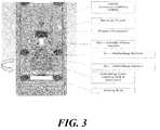
- FIG. 3is a plan view of an aspect of an electronic-control Lift-Handle in accordance with an embodiment of the invention.
- FIG. 4Ais a front perspective drawing of an aspect of an electronic-control Lift-Handle in accordance with an embodiment of the invention.
- FIG. 4Bis a back perspective drawing of an aspect of an electronic-control Lift-Handle in accordance with an embodiment of the invention.
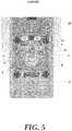
- FIG. 5is a plan view drawing of an aspect of an electronic-control Lift-Handle in accordance with an embodiment of the invention.
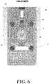
- FIG. 6is a plan view drawing of an aspect of an electronic-control Lift-Handle in accordance with an embodiment of the invention.
- FIG. 7is a plan view drawing of an aspect of an electronic-control Lift-Handle in accordance with an embodiment of the invention.
- FIG. 8is a plan view of an aspect of an electronic-control Lift-Handle in accordance with an embodiment of the invention.
- FIG. 9is a flow chart of an aspect of an electronic-control Lift-Handle in accordance with an embodiment of the invention.
- FIG. 10is a flow chart of an aspect of an electronic-control Lift-Handle in accordance with an embodiment of the invention.
- FIG. 11is a flow chart of an aspect of an electronic-control T-Handle in accordance with an embodiment of the invention.
- FIG. 12is a perspective drawing of an aspect of an electronic-control T-Handle in accordance with an embodiment of the invention.
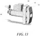
- FIG. 13is a perspective drawing of an aspect of an electronic-control T-Handle in accordance with an embodiment of the invention.
- FIG. 14is a perspective drawing of an aspect of an electronic-control T-Handle in accordance with an embodiment of the invention.
- FIG. 15is a plan view drawing of an aspect of an electronic-control T-Handle in accordance with an embodiment of the invention.
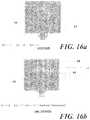
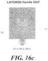
- FIGS. 16 a , 16 b and 16 care plan view drawings of an aspect of an electronic-control T-Handle in accordance with an embodiment of the invention.
- FIG. 17is a flow chart of an aspect of an electronic-control T-Handle in accordance with an embodiment of the invention.
- FIG. 18is a flow chart of an aspect of an electronic-control T-Handle in accordance with an embodiment of the invention.
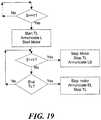
- FIG. 19is a flow chart of an aspect of an electronic-control T-Handle in accordance with an embodiment of the invention.
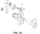
- FIG. 20is a perspective drawing of an aspect of an electronic-control T-Handle in accordance with an embodiment of the invention.
- FIG. 21is a perspective drawing of an aspect of an electronic-control T-Handle in accordance with an embodiment of the invention.
- FIG. 22is a perspective drawing of an aspect of an electronic-control T-Handle in accordance with an embodiment of the invention.
- FIG. 23is a plan view drawing of an aspect of an electronic-control T-Handle in accordance with an embodiment of the invention.
- FIG. 24is a perspective drawing of an aspect of an electronic-control T-Handle in accordance with an embodiment of the invention.
- FIG. 25is a perspective drawing of an aspect of an electronic-control T-Handle in accordance with an embodiment of the invention.
- FIG. 26is a perspective drawing of an aspect of an electronic-control T-Handle in accordance with an embodiment of the invention.
- this productis configured for mounting to the door of a cabinet, and attaches to latch hardware to latch the door to the cabinet.
- the productconsists of a handle 1 , housing 2 , slider bolt 3 , springs 4 , CAM 5 , motor 6 , circuit board controller 7 , cover 8 , eye 9 , handle sensor 10 , CAM sensors 11 , IRDA infrared transceiver 12 , Slider bolt pin 13 , Slider bolt guide 70 , Housing slot 71 .
- the handle 1seats in the housing 2 when the unit is in the latched or locked position.
- the eye 9attaches to the handle 1 , and is held in place by the slider bolt 3 when the unit is latched or locked.
- the motor 6serves to rotate CAM 5 by 360 degrees to change the state of handle 1 from locked to unlocked to latched.
- the slider bolt 3seats in the housing 2 and is biased downward to the latched position (See FIG. 7 ) by springs 4 .
- the slider bolt guide 70fits into housing slot 71 .
- the guide 70is centered on slider bolt 3 , and is configured to slide up and down in slot 71 to keep the slider bolt 3 aligned in the housing 2 , e.g., to keep it from tilting and from jamming as the slider bolt 3 slides or moves.
- the CAM 5controls the slider bolt 3 by being capable of keeping the slider bolt 3 in the locked position by surface 14 interfering with slider bolt pin 13 if there is an attempt to push the slider bolt 3 up to the unlocked position when the unit is locked (see FIG. 5 ).
- the CAM 5controls the slider bolt 3 by applying a force from surface 15 to the slider bolt along surface 16 when the motor 6 is rotated and when the unit is unlocked (see FIG. 6 ).
- the electronic controller 7controls the motor 6 to rotate the CAM 5 to the three positions noted above.
- the position of the CAM 5is controlled and sensed by two optical sensors 11 sensing the position of CAM 5 in the illustrated example.
- a handle position sensor 10is also utilized in an embodiment.
- An IRDA infrared transceiver 12is included for detecting an electronic key. The control of the unit is described in the flow charts of FIGS. 9, 10, and 11 .
- the unitis initially locked as in the configuration shown in FIG. 5 . If the controller IRDA infrared transceiver 12 detects the electronic key, cam 5 is rotated and applies an upward force to sliding bolt 3 along surface 16 to move the slider bolt 3 against the downward spring bias force and lift bolt 3 to the unlocked position reflected in FIG. 6 . Sensors 11 measure position of CAM 5 and provide a signal to the controller for determining proper control of the motor. Once in the unlocked position, the eye 9 attached to the handle 1 is released from interference by slider bolt 3 and handle 1 is capable of being lifted from housing 2 and optionally rotated.
- the controller 7senses the position of the handle 1 , and after the handle 1 is unlocked and the user proceeds to lift (and optionally rotate) the handle 1 to unlatch the door from the cabinet, the controller 7 proceeds to energize the motor 6 to move the CAM 5 to the latched position shown in FIG. 7 . In the latched position, the slider bolt 3 is biased to the position shown in FIG. 7 by one or more springs 4 .
- the handle 1when the user is finished accessing the cabinet, the handle 1 is pushed into the housing 2 , and the eye 9 pushes against the slider bolt 3 such that the slider bolt 3 is forced by the eye 9 upward against the bias of the springs 4 so as to lift up and allow the eye 9 to pass by the slider bolt 3 .
- the springs 4push the slider bolt 3 back to the latched position, capturing the eye 9 .
- the controller 7senses the handle 1 in the housing 2 via sensor 10 , then first waits for the eye 9 to pass under the slider bolt 3 as shown in FIG. 8 before proceeding to rotate the CAM 5 to the locked position shown in FIG. 5 .
- the CAM 5interferes at surface 14 with slide bolt pin 13 to maintain the slider bolt 3 in the locked position.
- the unitis less vulnerable to a thief or vandal attempting to defeat the lock by using either a tool or a vibration force to move the slider bolt 3 upward against the weaker downward force of springs 4 .
- the disclosed electronic control lift-handle productis an effective solution that is able to be mounted to the door of a cabinet, and to secure the door in a manner that overcomes some of the problems found in prior systems.
- the novel electronic control t-handle productwhile differently configured, is substantially as effective at providing a secure closure in a manner that overcomes problems in prior designs.
- the electronic control t-handle productconsists of a handle 51 , a housing 52 , latch hardware 65 , a MCU 64 and CPU control electronics (not shown).
- the housing 52is mounted to the door of a cabinet, and the latch hardware 65 is attached to a latch device that will operate to latch and unlatch the door to the cabinet.
- the MCU 64attaches to the body of the housing 52 , and the handle 51 resides inside of the housing 51 .
- the MCU 64is controlled by the CPU to latch, lock and unlock the handle 51 within the housing 52 .
- the handlepops-out of the housing 52 for the user to operate.
- the useroperates the handle 51 by turning it 1 ⁇ 4 turn (90 degrees) clock-wise to operate latch hardware 65 .
- the usercloses the cabinet door, turns the handle 51 1 ⁇ 4 turn in the counter-clockwise direction to re-latch the door to the cabinet.
- the userpushes the handle 51 in so as to lock the handle 51 into the housing 52 .
- the MCU 64consists of a slider bolt 53 , a spring 54 , a CAM 55 , a motor 56 , a mount 57 , a cover 58 , a handle sensor 60 , and one or more CAM sensors 61 .
- the handle 51seats in the housing 52 when the unit is in the latched or locked position, and is locked into the housing 52 by the slider bolt 53 protruding into handle slot 59 when the unit is latched or locked.
- the motor 56serves to rotate the CAM 55 through 360 degrees to change the state of the handle 51 from locked, to unlocked, to latched.
- the slider bolt 53is biased to be latched in the downward position into slot 59 by spring 54 as shown in FIG. 14 .
- the CAM 5controls the slider bolt 53 by applying a force from surface 66 to the slider bolt 53 surface 67 if there is an attempt to push the bolt toward the upward unlocked position when the unit is locked as shown in FIGS. 15 and 16A .
- the CAM 5further controls the slider bolt 53 by applying a force from surface 66 to the slider bolt along surface 69 when the motor 56 is rotated and when the unit is unlocked as shown in FIG. 16B .
- the electronic controller CPUcontrols motor 56 to rotate CAM 55 to three positions.
- the position to which CAM 55 is controlled or rotatedis sensed by two optical sensors 61 sensing the position of CAM 55 .
- a handle position sensor 60is also utilized.
- An IRDA infrared transceiver(not shown) is included for detecting an electronic key. The control of the unit is described in the flow charts of FIGS. 17, 18, and 19 .
- the unitis initially locked as shown in FIGS. 15 and 16A . If the controller IRDA infrared transceiver detects the electronic key, the cam 55 is rotated and applies an upward force to the sliding bolt 53 along surface 69 to move the slider bolt 53 against the downward spring bias force and lift bolt 53 to the unlocked position as shown in FIG. 16B .
- the sensors 61measure the position of the CAM 55 and provide a signal to the controller for determining proper control of the motor.
- the position sensor 60 and the CPU controllersense the position of the handle 51 , and after the handle 51 is unlocked and the user proceeds to rotate the handle 51 to unlatch the door from the cabinet, the controller proceeds to energize the motor 56 to move the CAM 55 to the latched position in FIG. 16C . In the latched position, the slider bolt 3 is biased by the spring 54 to the position shown in FIG. 16C .
- the handle 51when the user is finished accessing the cabinet, the handle 51 is pushed into housing 52 when causing a surface of the handle 51 to push against the slider bolt 53 , such that the slider bolt 53 is forced upward against the bias of spring 54 so as to lift upward to allow the handle 51 to protrude into the housing 52 .
- the spring 4will push the slider bolt 53 back to the latched position to hold the handle 51 into the housing 52 .
- the controllersensing via sensor 60 that the handle 51 is in the housing 52 , will first wait for slot 59 to pass under the slider bolt 53 and will then rotate the CAM 55 to the locked position as shown in FIG. 16A .
- the CAM 55will apply a force at surface 66 to the slider bolt 53 at surface 67 to maintain the slider bolt 53 in the locked position in the event that an attempt is made to manually lift the slider bolt 53 upward.
- the unitis less vulnerable to a thief or vandal attempting to defeat the lock using a tool or a vibration force to move slider bolt 53 upward against the weaker downward force of spring 54 .
- FIG. 20is drawing of an alternate embodiment of the MCU with a sensor 80 for detecting the slider bolt 81 .
- the controllercan identify the position of the handle, whether it is unlocked and extended with the slider in the retracted position or locked and in the extended position.
- This sensorcan be used in conjunction with or in place of handle detector switch 60 .
- FIG. 21shows an alternate optional mounting position of the MCU on the t-handle housing at the 3:00 position.
- Alternate mounting positionswill be useful in retrofit applications whereby a vending machine may have other accessories mounted around the T-handle, and the installer requires the flexibility of mounting the MCU at either the 12:00 (as in FIG. 13 ), 3:00 ( FIG. 21 ), 6:00 or 9:00 positions, i.e., whichever position is unobstructed and allows the position of the MCU to not interfere with pre-existing accessory equipment in the machine.
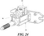
- FIGS. 22-26show an alternative design 82 of the MCU, whereby the MCU will mount to housing 83 which was pre-installed in vending machines.
- the pre-installed housingwould normally house a standard t-handle and a lock plug/core operated by a mechanical key.
- the pre-installed housingwill remain in the machine.
- MCU 82is similar to MCU 64 except for the way it slides onto and fastens to pre-existing housing 83 .
- MCU 82has legs 86 that will extend along the vertical surfaces of housing 83 , and the rear view of MCU 82 in FIG. 23 shows the MCU surfaces that could potentially touch housing 83 during installation, such as horizontal edges 87 , 88 , 89 , 94 , 95 and vertical surfaces 90 , 91 , 92 , and 93 that will capture housing 83 at least partially along multiple outer surfaces of housing 83 .
- Fastener 96is used to fasten the MCU to the housing once seated.
- the installerwould apply the MCU 82 by sliding the MCU 82 on the pre-existing housing at for example the 12:00 position as shown in FIG. 24 .
- MCU 82slides on housing 83 and seats until the rear end of MCU 82 is flush with the rear end of housing 83 and fastened by fastener 96 as shown in FIG. 25 .
- the installerwould fasten the MCU to the housing by turning fastener 96 thereby fastening the MCU to the housing.
- the MCU 82can be fastened by fastener 96 with a tool at the rear of the housing as shown, and/or the MCU can also be fastened by a fastener on the inside of the housing with a tool that travels inside the housing to reach the fastener.
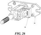
- the MCU 82can also be installed at the 3:00, 6:00 or 9:00 positions; position 3:00 is shown by way of example in FIG. 26 .
- the fastener 96can be operated by a tool inserted into the head of the fastener, such as a flathead screw, or the fastener head can be inside the MCU 82 and operated by inserting the tool into the front of the housing to operate the fastener head after the MCU is seated on the housing.
Landscapes
- Lock And Its Accessories (AREA)
Abstract
Description
Claims (12)
Priority Applications (1)
| Application Number | Priority Date | Filing Date | Title |
|---|---|---|---|
| US13/866,525US11002039B2 (en) | 2012-04-20 | 2013-04-19 | Electronic controlled handles |
Applications Claiming Priority (2)
| Application Number | Priority Date | Filing Date | Title |
|---|---|---|---|
| US201261636263P | 2012-04-20 | 2012-04-20 | |
| US13/866,525US11002039B2 (en) | 2012-04-20 | 2013-04-19 | Electronic controlled handles |
Publications (2)
| Publication Number | Publication Date |
|---|---|
| US20130285393A1 US20130285393A1 (en) | 2013-10-31 |
| US11002039B2true US11002039B2 (en) | 2021-05-11 |
Family
ID=49476625
Family Applications (1)
| Application Number | Title | Priority Date | Filing Date |
|---|---|---|---|
| US13/866,525Active2035-10-10US11002039B2 (en) | 2012-04-20 | 2013-04-19 | Electronic controlled handles |
Country Status (1)
| Country | Link |
|---|---|
| US (1) | US11002039B2 (en) |
Cited By (2)
| Publication number | Priority date | Publication date | Assignee | Title |
|---|---|---|---|---|
| US20220282535A1 (en)* | 2019-08-13 | 2022-09-08 | Ron Zeitler | Quarter turn twist lock door latch |
| US11639617B1 (en) | 2019-04-03 | 2023-05-02 | The Chamberlain Group Llc | Access control system and method |
Families Citing this family (17)
| Publication number | Priority date | Publication date | Assignee | Title |
|---|---|---|---|---|
| WO2014186475A1 (en) | 2013-05-15 | 2014-11-20 | Calin Roatis | Lock |
| US9466190B2 (en)* | 2013-12-17 | 2016-10-11 | Brady Worldwide, Inc. | Enclosure assembly for securing a door |
| CN103758409B (en)* | 2014-01-20 | 2016-08-17 | 林挺意 | The automatically controlled lock plunger control device of electronic password lock |
| US10344502B2 (en)* | 2016-02-04 | 2019-07-09 | Schlage Lock Company Llc | User sensing exit device |
| USD806502S1 (en)* | 2016-06-27 | 2018-01-02 | Fath, Inc. | Security lever handle assembly |
| CN106088813B (en)* | 2016-08-18 | 2018-07-24 | 林挺意 | A kind of device for control hand handle idle running in theftproof lock |
| USD868560S1 (en)* | 2017-05-30 | 2019-12-03 | Rittal Gmbh & Co. Kg | Door handle for switchgear cabinets |
| US11021894B1 (en)* | 2017-11-14 | 2021-06-01 | Smart Armor Protected, LLC | Power-activated cam lock |
| CN109519053B (en)* | 2018-12-03 | 2023-11-28 | 珠海优特电力科技股份有限公司 | Intelligent panel lock |
| CN109914934A (en)* | 2019-04-01 | 2019-06-21 | 河南传通电子科技有限公司 | A kind of intelligent case monitoring management system based on Internet of Things |
| US12012167B2 (en) | 2019-04-19 | 2024-06-18 | Lyft, Inc. | Apparatus, systems, and methods for rotating lock cables |
| US10577834B1 (en) | 2019-04-19 | 2020-03-03 | Lyft, Inc. | Systems and methods for magnet-equipped locks |
| US10689046B1 (en) | 2019-04-19 | 2020-06-23 | Lyft, Inc. | Apparatus, systems, and methods for single-sided locks |
| US12359465B2 (en) | 2021-02-16 | 2025-07-15 | Triteq Lock And Security, Llc | Lock |
| GB2605452A (en)* | 2021-04-01 | 2022-10-05 | Era Home Security Ltd | Improved Door Lock |
| USD1031413S1 (en)* | 2022-04-25 | 2024-06-18 | Truth Hardware Corporation | Window operator handle and cover |
| EP4563773A1 (en)* | 2023-11-29 | 2025-06-04 | Industrilås i Nässjö Aktiebolag | Locking arrangement and door arrangement comprising a locking arrangement |
Citations (133)
| Publication number | Priority date | Publication date | Assignee | Title |
|---|---|---|---|---|
| US1370190A (en)* | 1920-01-19 | 1921-03-01 | James L Cook | Steering-gear-locking mechanism |
| US1875768A (en) | 1931-03-09 | 1932-09-06 | Franklin P Smith | Sliding doorlock |
| US1907625A (en) | 1930-03-24 | 1933-05-09 | Knape & Vogt Mfg Co | Showcase sliding doorlock |
| US2269264A (en) | 1941-03-04 | 1942-01-06 | Haim Albert | Swing lock fastener |
| US2703431A (en) | 1953-01-12 | 1955-03-08 | Jean H Tatom | Latch hinge |
| US2741503A (en) | 1953-11-20 | 1956-04-10 | Iii Iverson G Thompson | Motorized locking means |
| US2753202A (en) | 1955-01-11 | 1956-07-03 | Ford Motor Co | Lock mechanism |
| US2833536A (en) | 1956-11-13 | 1958-05-06 | Gen Motors Corp | Power operated rear compartment actuator and lock assembly |
| US2877637A (en) | 1956-03-14 | 1959-03-17 | Greenwald Co Inc H | Locked coin drawer |
| US2896990A (en) | 1956-01-06 | 1959-07-28 | Gen Motors Corp | Vehicle closure latch |
| US2903288A (en) | 1956-09-27 | 1959-09-08 | Gen Motors Corp | Latch striker mechanism |
| US2943880A (en) | 1958-07-30 | 1960-07-05 | Gen Motors Corp | Closure latch |
| US2978266A (en) | 1958-08-12 | 1961-04-04 | Hartwell Aviat Supply Co | Sliding and rotating bolt latch |
| US3080633A (en) | 1960-06-29 | 1963-03-12 | Hi Shear Rivet Tool Company | Separable fastener |
| US3081078A (en) | 1959-05-28 | 1963-03-12 | Gen Motors Corp | Deck lid latch and actuator |
| US3089330A (en) | 1961-12-07 | 1963-05-14 | Chicago Lock Co | Lock assembly for a refrigerated cabinet or the like |
| US3200623A (en) | 1963-07-09 | 1965-08-17 | Gen Motors Corp | Latch actuating means |
| US3285043A (en)* | 1964-06-19 | 1966-11-15 | Nat Lock Co | Pop-out handle and lock construction |
| US3302434A (en)* | 1964-06-19 | 1967-02-07 | Nat Lock Co | Pop-out handle and lock assembly |
| US3438227A (en)* | 1966-07-13 | 1969-04-15 | Illinois Lock Co | Pop handle lock |
| US3548618A (en)* | 1969-03-10 | 1970-12-22 | Keystone Consolidated Ind Inc | Pop-out handle and locking device |
| US3550412A (en) | 1968-04-16 | 1970-12-29 | Automatic Merchandising Mach | Door lock |
| US3594876A (en) | 1969-10-15 | 1971-07-27 | Dzus Fastener Co | Fastener having improved load-carrying capacity |
| US3688352A (en) | 1969-10-15 | 1972-09-05 | Dzus Fastener Co | Fastener having improved-load carrying capacity |
| US3834198A (en)* | 1972-10-02 | 1974-09-10 | M Wiczer | Lock anti-pick device |
| US3835678A (en) | 1973-08-29 | 1974-09-17 | Gen Motors Corp | Vehicle body compartment panel pull-down mechanism |
| US3854310A (en) | 1972-01-07 | 1974-12-17 | Constellation Corp | Electric control motor driven lock mechanism |
| US3947060A (en) | 1975-02-26 | 1976-03-30 | Pulse Dynamics Manufacturing Corporation | Bolt mechanism with manual override |
| US4159138A (en) | 1977-11-08 | 1979-06-26 | Smith Donald V | Snap-acting latch mechanism for sliding doors and the like |
| US4167104A (en) | 1977-11-21 | 1979-09-11 | Coca-Cola Bottling Works Company | Solenoid enabled lock for vending machines and the like |
| US4213230A (en) | 1978-06-30 | 1980-07-22 | Simmons Fastener Corporation | Rotatable locking fastener |
| US4227723A (en) | 1977-09-16 | 1980-10-14 | Laperche | Multiple bolt latch |
| US4268076A (en) | 1977-09-27 | 1981-05-19 | Kabushiki Kaisha Itoi Seisakusho | Cash box provided with a till |
| US4300664A (en) | 1978-11-27 | 1981-11-17 | Decoto Aircraft, Inc. | Locking device |
| US4355830A (en) | 1980-02-25 | 1982-10-26 | Cni Incorporated | Electrical locking mechanism |
| US4411544A (en) | 1981-07-31 | 1983-10-25 | Loose Leaf Metals Company, Inc. | Post binder ball lock assembly |
| US4552001A (en) | 1983-12-06 | 1985-11-12 | Medeco Security Locks, Inc. | High security T-handle assembly |
| US4556244A (en) | 1984-01-26 | 1985-12-03 | Southco, Inc. | Latch assembly having pull-up action |
| US4583775A (en) | 1984-05-16 | 1986-04-22 | Southco, Inc. | Latch assembly having pull-up action |
| US4594637A (en) | 1985-02-21 | 1986-06-10 | Sidney Falk | Digital electronic lock system |
| US4609215A (en) | 1984-08-20 | 1986-09-02 | The United States Of America As Represented By The Secretary Of The Navy | Hydraulic locking boltwork system |
| US4671547A (en) | 1985-07-31 | 1987-06-09 | The Eastern Company | Half turn cabinet latch with door gasket clamping capability |
| US4685709A (en) | 1984-05-29 | 1987-08-11 | R. R. Brink Locking Systems, Inc. | Deadlocked latch having disc and motor actuators |
| US4689976A (en)* | 1986-06-16 | 1987-09-01 | Tri/Mark Corporation | Pop-up handle assembly |
| US4744392A (en) | 1987-02-27 | 1988-05-17 | Combustion Engineering, Inc. | Nozzle dam segment bolt and keeper |
| US4760721A (en) | 1986-01-27 | 1988-08-02 | Chicago Lock Company | Handle flange assembly |
| US4762348A (en) | 1985-10-30 | 1988-08-09 | Ohi Seisakusho Co., Ltd. | Electric door lock system |
| US4796932A (en) | 1987-09-22 | 1989-01-10 | Hoover Universal, Inc. | Remote release and pull-down unit |
| US4803460A (en) | 1987-05-18 | 1989-02-07 | Ford Motor Company | Anti-theft system |
| US4819983A (en) | 1987-09-24 | 1989-04-11 | Asc Incorporated | Power latch system |
| US4838055A (en)* | 1988-05-02 | 1989-06-13 | Gallagher Francis E | Anti-thief key lock for vending machines |
| US4842313A (en) | 1987-11-12 | 1989-06-27 | Masco Industries, Inc. | Automatic vehicle striker powered by a unidirectional motor |
| US4899581A (en) | 1988-02-19 | 1990-02-13 | Massachusetts Institute Of Technology | Method and apparatus for the quantitative measurement of adhesion of thin films |
| US4906035A (en) | 1987-12-02 | 1990-03-06 | Fuji Jukogyo Kabushiki Kaisha | Automatic locking device for trunk lid of motor vehicle |
| JPH0291371A (en) | 1988-09-29 | 1990-03-30 | Olympic Co Ltd | motor lock safe |
| US4993247A (en) | 1989-09-13 | 1991-02-19 | Sanpo Lock Co., Ltd. | Lock for automatic vending machines |
| US5035452A (en) | 1988-12-17 | 1991-07-30 | Bomoro, Bocklenberg & Motte Gmbh & Co. Kg | Vehicle door latches |
| US5038588A (en)* | 1990-08-07 | 1991-08-13 | Medeco Security Locks, Inc. | High security T-handle lock assembly with front handle improvements |
| US5054300A (en) | 1988-11-09 | 1991-10-08 | Ohi Seisakusho Co., Ltd. | Vehicle door lock system |
| US5106251A (en) | 1990-07-16 | 1992-04-21 | Chicago Lock Company | Automatic locking device for pop out handle locks |
| US5148691A (en) | 1989-06-29 | 1992-09-22 | Assa Ab | Electrically and mechanically activatable lock mechanism |
| US5160180A (en) | 1991-10-18 | 1992-11-03 | Chicago Lock Company | Automatic quick open/close locking mechanism |
| US5186516A (en) | 1987-09-24 | 1993-02-16 | Asc Incorporated | Power latch system |
| US5199288A (en) | 1990-10-24 | 1993-04-06 | Abloy Security Ltd. Oy | Electromechanical door lock |
| US5269161A (en) | 1989-09-06 | 1993-12-14 | Star Lock Systems, Inc. | Latching system |
| US5272894A (en) | 1989-03-22 | 1993-12-28 | Star Lock Systems, Inc. | Fractional-rotation latching system with retrofit capability |
| US5349345A (en) | 1992-06-30 | 1994-09-20 | Vindicator Corporation | Electronic lock |
| US5394718A (en) | 1992-04-01 | 1995-03-07 | Roto Frank Eisenwarenfabrik Aktiengesellschaft | Power-assist slide lock |
| US5467619A (en) | 1989-03-22 | 1995-11-21 | Star Lock Systems, Inc. | Post latching systems |
| US5548982A (en) | 1994-07-19 | 1996-08-27 | Rawling; James | Security bolt for T-handle assembly with retrofit capability |
| US5561420A (en)* | 1994-08-16 | 1996-10-01 | Kiekert Aktiengesellschaft | Motor-vehicle central lock system with transponder in key |
| US5575515A (en) | 1994-02-10 | 1996-11-19 | Fuji Electric Co., Ltd. | Door locking apparatus for dispenser |
| US5586459A (en)* | 1995-05-16 | 1996-12-24 | A. L. Hansen Mfg. Co. | Locking handle |
| US5617082A (en) | 1994-11-15 | 1997-04-01 | Micro Enhanced Technology, Inc. | Electronic access control device utilizing a single microcomputer integrated circuit |
| US5618082A (en) | 1996-09-16 | 1997-04-08 | Jachmich; Manfred F. | Quick install cover for a seat |
| US5636881A (en) | 1994-10-21 | 1997-06-10 | Star Lock Systems, Inc. | Automatic latching system with automated unlatching feature |
| US5639130A (en) | 1995-05-31 | 1997-06-17 | General Motors Corporation | Rotary door cinching mechanism with manual override |
| US5656867A (en) | 1995-04-11 | 1997-08-12 | Kabushiki Kaisha Tokai-Rika-Denki-Seisakusho | Vehicular starting control device using an ID code to control ignition switch rotation and steering lock operation |
| US5680783A (en) | 1994-08-31 | 1997-10-28 | Mitsui Kinzoku Kogyo Kabushiki Kaisha | Door lock device with anti-theft mechanism |
| US5782384A (en) | 1996-11-05 | 1998-07-21 | Colgate-Palmolive | Aligned web in a container |
| US5793122A (en) | 1996-06-11 | 1998-08-11 | Motor Vehicle Protection Systems, Inc. | Automobile security device |
| US5791179A (en) | 1996-08-08 | 1998-08-11 | Brask; James E. | Remote control motor driven locking mechanism |
| US5813257A (en) | 1997-06-25 | 1998-09-29 | Coin Acceptors, Inc. | Electrically controllable locking device for vending machines and the like |
| US5823027A (en) | 1994-03-30 | 1998-10-20 | Dallas Semiconductor Corporation | Electrical/mechanical access control systems and methods |
| US5836187A (en)* | 1994-06-03 | 1998-11-17 | Strattec Security Corporation | Tumberless automobile ignition lock |
| US5839305A (en)* | 1994-09-03 | 1998-11-24 | Yale Security Products Limited | Electrically operable cylinder lock |
| US5862693A (en) | 1997-05-02 | 1999-01-26 | Fort Lock Corporation | Electronically controlled security lock |
| US5870915A (en)* | 1994-11-30 | 1999-02-16 | Texas Instruments Incorporated | Key lock having inductive key detection and method of construction |
| US5882053A (en)* | 1996-06-14 | 1999-03-16 | Donnelly Corporation | Vehicle door/tailgate assembly with centering feature |
| US5915766A (en) | 1996-07-20 | 1999-06-29 | Kendro Laboratory Products Gmbh | Locking device |
| US5921119A (en) | 1996-08-01 | 1999-07-13 | Fort Lock Corporation | Pop-out handle lock assembly |
| US6005487A (en) | 1990-05-11 | 1999-12-21 | Medeco Security Locks, Inc. | Electronic security system with novel electronic T-handle lock |
| US6046681A (en) | 1997-11-07 | 2000-04-04 | Solop; John | Remote controlled door lock system |
| US6049287A (en) | 1998-03-02 | 2000-04-11 | Yulkowski; Leon | Door with integrated smoke detector and hold open |
| US6068308A (en) | 1998-03-13 | 2000-05-30 | Austin Hardware, Inc. | Latch assembly |
| US6068305A (en) | 1997-07-09 | 2000-05-30 | Fort Lock Corporation | Lock assembly for vending machines and method for locking and unlocking same |
| US6068487A (en) | 1998-10-20 | 2000-05-30 | Lernout & Hauspie Speech Products N.V. | Speller for reading system |
| US6106035A (en) | 1997-11-17 | 2000-08-22 | Maysteel Corporation | Locking mechanism for transformer enclosure door |
| US6130611A (en) | 1997-10-14 | 2000-10-10 | Ilco-Unican S.A./Rehlor Division | Locking system for entry door to a security enclosure, able to control the development of a parameter linked to the environment of the enclosure |
| US6196037B1 (en) | 1998-01-02 | 2001-03-06 | Sargent & Greenleaf, Inc. | Lock system enabling user to lock door and extend lock bolt in a single action and push-pull lock with cushioning arrangement for protecting bolt drive components |
| US6256932B1 (en) | 1999-06-29 | 2001-07-10 | Daimlerchrysler Corporation | Electronically-controlled vehicle door system |
| US6318138B1 (en)* | 1999-11-15 | 2001-11-20 | Kurt Mathews | Remotely controlled door lock |
| US6341448B1 (en) | 1997-08-13 | 2002-01-29 | Atoma International Corp. | Cinching latch |
| US6345522B1 (en) | 1998-08-12 | 2002-02-12 | Star Lock Systems, Inc. | Electro-mechanical latching apparatus |
| US6360573B1 (en) | 2000-09-11 | 2002-03-26 | Summit Automation Co., Ltd | Mechanism for locking and unlocking electronic safe lock barrel |
| US6370928B1 (en) | 1997-10-03 | 2002-04-16 | Ezio Chies | Mechano-electronically operated cylinder-key unit for locks |
| US6374649B1 (en) | 1999-02-04 | 2002-04-23 | Waterloo Industries, Inc. | Electronic remote entry lock system for a tool cabinet |
| US6382003B1 (en)* | 1999-06-11 | 2002-05-07 | Nissan Motor Co., Ltd. | Lock apparatus |
| US6406071B1 (en) | 1999-03-09 | 2002-06-18 | Elastolatch, Inc. | Two-piece flexible latch and handle having adjustable lengths |
| US20020078722A1 (en)* | 2000-12-21 | 2002-06-27 | Jan's Iron Works, Inc. | Lock protector for dispensing machines |
| US6442986B1 (en)* | 1998-04-07 | 2002-09-03 | Best Lock Corporation | Electronic token and lock core |
| US6474119B1 (en) | 1999-01-28 | 2002-11-05 | Fastec Industrial Corp. | Pop-up handle assembly |
| US6490896B2 (en) | 2001-04-23 | 2002-12-10 | Takigen Manufacturing Co., Ltd. | Door locking handle assembly of pull-out and side-swinging lever-action type |
| US6496101B1 (en) | 1998-08-12 | 2002-12-17 | Star Lock Systems, Inc. | Electro-mechanical latch assembly |
| US6543264B2 (en) | 2001-07-30 | 2003-04-08 | Harrow Products, Inc. | Mortise lockset with internal clutch having override feature |
| US6564600B1 (en) | 1999-03-08 | 2003-05-20 | Videx, Inc. | Electronic access control device |
| US6575504B2 (en) | 2000-11-21 | 2003-06-10 | Triteq Lock And Security, L.L.C. | Bayonet locking system and method for vending machines and the like |
| US6580355B1 (en) | 1999-06-11 | 2003-06-17 | T.K.M. Unlimited, Inc. | Remote door entry system |
| US6581986B2 (en) | 2000-11-21 | 2003-06-24 | Tri Teq Lock And Security, L.L.C. | Bayonet locking system and method for vending machines and the like |
| US20030127866A1 (en) | 2001-12-14 | 2003-07-10 | Martinez Richard A. | Electromechanical locking mechanism |
| US6609402B2 (en)* | 2000-04-06 | 2003-08-26 | Schlage Lock Company | Electronic key assembly with spring loaded data pin and contact |
| US6615623B1 (en) | 1998-09-30 | 2003-09-09 | Vending Management Services, Ltd. | Vending machine lock arrangements |
| US6684671B2 (en) | 2000-11-02 | 2004-02-03 | Best Lock Corporation | Vending machine lock |
| US20040172991A1 (en) | 2003-03-05 | 2004-09-09 | Patrick Forster | Vending machine locking device |
| US6826935B2 (en)* | 1997-12-22 | 2004-12-07 | Security People, Inc. | Mechanical/electronic lock and key therefor |
| US6867685B1 (en) | 1999-05-10 | 2005-03-15 | Star Lock Systems, Inc. | Electro-mechanical lock assembly |
| US7073827B2 (en) | 2002-04-14 | 2006-07-11 | Southco, Inc. | Electromechanical latching system |
| US7089770B2 (en) | 2000-04-06 | 2006-08-15 | Dirak Dieter Ramsauer Konstruktionselemente Gmbh & Co. Kg | Electrically blockable swiveling lever control |
| US7145434B2 (en) | 2003-04-21 | 2006-12-05 | Compx International Inc. | System and method for key control in an electronic locking system |
| US7296447B2 (en) | 2005-02-24 | 2007-11-20 | The Stanley Works | Vending machine lock assembly |
| US7469564B1 (en)* | 2004-02-26 | 2008-12-30 | Shaw Barry M | Second improved electromagnetic integrative door locking device and method of installation |
| US7681424B2 (en) | 2006-04-16 | 2010-03-23 | Southco, Inc. | Swing handle latch |
| US7845202B2 (en)* | 2006-09-22 | 2010-12-07 | Assa Abloy Ab | Interchangeable electromechanical lock core |
- 2013
- 2013-04-19USUS13/866,525patent/US11002039B2/enactiveActive
Patent Citations (140)
| Publication number | Priority date | Publication date | Assignee | Title |
|---|---|---|---|---|
| US1370190A (en)* | 1920-01-19 | 1921-03-01 | James L Cook | Steering-gear-locking mechanism |
| US1907625A (en) | 1930-03-24 | 1933-05-09 | Knape & Vogt Mfg Co | Showcase sliding doorlock |
| US1875768A (en) | 1931-03-09 | 1932-09-06 | Franklin P Smith | Sliding doorlock |
| US2269264A (en) | 1941-03-04 | 1942-01-06 | Haim Albert | Swing lock fastener |
| US2703431A (en) | 1953-01-12 | 1955-03-08 | Jean H Tatom | Latch hinge |
| US2741503A (en) | 1953-11-20 | 1956-04-10 | Iii Iverson G Thompson | Motorized locking means |
| US2753202A (en) | 1955-01-11 | 1956-07-03 | Ford Motor Co | Lock mechanism |
| US2896990A (en) | 1956-01-06 | 1959-07-28 | Gen Motors Corp | Vehicle closure latch |
| US2877637A (en) | 1956-03-14 | 1959-03-17 | Greenwald Co Inc H | Locked coin drawer |
| US2903288A (en) | 1956-09-27 | 1959-09-08 | Gen Motors Corp | Latch striker mechanism |
| US2833536A (en) | 1956-11-13 | 1958-05-06 | Gen Motors Corp | Power operated rear compartment actuator and lock assembly |
| US2943880A (en) | 1958-07-30 | 1960-07-05 | Gen Motors Corp | Closure latch |
| US2978266A (en) | 1958-08-12 | 1961-04-04 | Hartwell Aviat Supply Co | Sliding and rotating bolt latch |
| US3081078A (en) | 1959-05-28 | 1963-03-12 | Gen Motors Corp | Deck lid latch and actuator |
| US3080633A (en) | 1960-06-29 | 1963-03-12 | Hi Shear Rivet Tool Company | Separable fastener |
| US3089330A (en) | 1961-12-07 | 1963-05-14 | Chicago Lock Co | Lock assembly for a refrigerated cabinet or the like |
| US3200623A (en) | 1963-07-09 | 1965-08-17 | Gen Motors Corp | Latch actuating means |
| US3302434A (en)* | 1964-06-19 | 1967-02-07 | Nat Lock Co | Pop-out handle and lock assembly |
| US3285043A (en)* | 1964-06-19 | 1966-11-15 | Nat Lock Co | Pop-out handle and lock construction |
| US3438227A (en)* | 1966-07-13 | 1969-04-15 | Illinois Lock Co | Pop handle lock |
| US3550412A (en) | 1968-04-16 | 1970-12-29 | Automatic Merchandising Mach | Door lock |
| US3548618A (en)* | 1969-03-10 | 1970-12-22 | Keystone Consolidated Ind Inc | Pop-out handle and locking device |
| US3594876A (en) | 1969-10-15 | 1971-07-27 | Dzus Fastener Co | Fastener having improved load-carrying capacity |
| US3688352A (en) | 1969-10-15 | 1972-09-05 | Dzus Fastener Co | Fastener having improved-load carrying capacity |
| US3854310A (en) | 1972-01-07 | 1974-12-17 | Constellation Corp | Electric control motor driven lock mechanism |
| US3834198A (en)* | 1972-10-02 | 1974-09-10 | M Wiczer | Lock anti-pick device |
| US3835678A (en) | 1973-08-29 | 1974-09-17 | Gen Motors Corp | Vehicle body compartment panel pull-down mechanism |
| US3947060A (en) | 1975-02-26 | 1976-03-30 | Pulse Dynamics Manufacturing Corporation | Bolt mechanism with manual override |
| US4227723A (en) | 1977-09-16 | 1980-10-14 | Laperche | Multiple bolt latch |
| US4268076A (en) | 1977-09-27 | 1981-05-19 | Kabushiki Kaisha Itoi Seisakusho | Cash box provided with a till |
| US4159138A (en) | 1977-11-08 | 1979-06-26 | Smith Donald V | Snap-acting latch mechanism for sliding doors and the like |
| US4167104A (en) | 1977-11-21 | 1979-09-11 | Coca-Cola Bottling Works Company | Solenoid enabled lock for vending machines and the like |
| US4213230A (en) | 1978-06-30 | 1980-07-22 | Simmons Fastener Corporation | Rotatable locking fastener |
| US4300664A (en) | 1978-11-27 | 1981-11-17 | Decoto Aircraft, Inc. | Locking device |
| US4355830A (en) | 1980-02-25 | 1982-10-26 | Cni Incorporated | Electrical locking mechanism |
| US4411544A (en) | 1981-07-31 | 1983-10-25 | Loose Leaf Metals Company, Inc. | Post binder ball lock assembly |
| US4552001A (en) | 1983-12-06 | 1985-11-12 | Medeco Security Locks, Inc. | High security T-handle assembly |
| US4556244A (en) | 1984-01-26 | 1985-12-03 | Southco, Inc. | Latch assembly having pull-up action |
| US4583775A (en) | 1984-05-16 | 1986-04-22 | Southco, Inc. | Latch assembly having pull-up action |
| US4685709A (en) | 1984-05-29 | 1987-08-11 | R. R. Brink Locking Systems, Inc. | Deadlocked latch having disc and motor actuators |
| US4609215A (en) | 1984-08-20 | 1986-09-02 | The United States Of America As Represented By The Secretary Of The Navy | Hydraulic locking boltwork system |
| US4594637A (en) | 1985-02-21 | 1986-06-10 | Sidney Falk | Digital electronic lock system |
| US4671547A (en) | 1985-07-31 | 1987-06-09 | The Eastern Company | Half turn cabinet latch with door gasket clamping capability |
| US4762348A (en) | 1985-10-30 | 1988-08-09 | Ohi Seisakusho Co., Ltd. | Electric door lock system |
| US4760721A (en) | 1986-01-27 | 1988-08-02 | Chicago Lock Company | Handle flange assembly |
| US4689976A (en)* | 1986-06-16 | 1987-09-01 | Tri/Mark Corporation | Pop-up handle assembly |
| US4744392A (en) | 1987-02-27 | 1988-05-17 | Combustion Engineering, Inc. | Nozzle dam segment bolt and keeper |
| US4803460A (en) | 1987-05-18 | 1989-02-07 | Ford Motor Company | Anti-theft system |
| US4796932A (en) | 1987-09-22 | 1989-01-10 | Hoover Universal, Inc. | Remote release and pull-down unit |
| US4819983A (en) | 1987-09-24 | 1989-04-11 | Asc Incorporated | Power latch system |
| US5186516A (en) | 1987-09-24 | 1993-02-16 | Asc Incorporated | Power latch system |
| US4842313A (en) | 1987-11-12 | 1989-06-27 | Masco Industries, Inc. | Automatic vehicle striker powered by a unidirectional motor |
| US4906035A (en) | 1987-12-02 | 1990-03-06 | Fuji Jukogyo Kabushiki Kaisha | Automatic locking device for trunk lid of motor vehicle |
| US4899581A (en) | 1988-02-19 | 1990-02-13 | Massachusetts Institute Of Technology | Method and apparatus for the quantitative measurement of adhesion of thin films |
| US4838055A (en)* | 1988-05-02 | 1989-06-13 | Gallagher Francis E | Anti-thief key lock for vending machines |
| US4917022A (en) | 1988-09-29 | 1990-04-17 | Olympic Co., Ltd. | Safe having motor-driven locking mechanism |
| JPH0291371A (en) | 1988-09-29 | 1990-03-30 | Olympic Co Ltd | motor lock safe |
| US5054300A (en) | 1988-11-09 | 1991-10-08 | Ohi Seisakusho Co., Ltd. | Vehicle door lock system |
| US5035452A (en) | 1988-12-17 | 1991-07-30 | Bomoro, Bocklenberg & Motte Gmbh & Co. Kg | Vehicle door latches |
| US5467619A (en) | 1989-03-22 | 1995-11-21 | Star Lock Systems, Inc. | Post latching systems |
| US5272894A (en) | 1989-03-22 | 1993-12-28 | Star Lock Systems, Inc. | Fractional-rotation latching system with retrofit capability |
| US5148691A (en) | 1989-06-29 | 1992-09-22 | Assa Ab | Electrically and mechanically activatable lock mechanism |
| US5269161A (en) | 1989-09-06 | 1993-12-14 | Star Lock Systems, Inc. | Latching system |
| US4993247A (en) | 1989-09-13 | 1991-02-19 | Sanpo Lock Co., Ltd. | Lock for automatic vending machines |
| US6005487A (en) | 1990-05-11 | 1999-12-21 | Medeco Security Locks, Inc. | Electronic security system with novel electronic T-handle lock |
| US5106251A (en) | 1990-07-16 | 1992-04-21 | Chicago Lock Company | Automatic locking device for pop out handle locks |
| US5038588A (en)* | 1990-08-07 | 1991-08-13 | Medeco Security Locks, Inc. | High security T-handle lock assembly with front handle improvements |
| US5199288A (en) | 1990-10-24 | 1993-04-06 | Abloy Security Ltd. Oy | Electromechanical door lock |
| US5160180A (en) | 1991-10-18 | 1992-11-03 | Chicago Lock Company | Automatic quick open/close locking mechanism |
| US5394718A (en) | 1992-04-01 | 1995-03-07 | Roto Frank Eisenwarenfabrik Aktiengesellschaft | Power-assist slide lock |
| US5349345A (en) | 1992-06-30 | 1994-09-20 | Vindicator Corporation | Electronic lock |
| US5575515A (en) | 1994-02-10 | 1996-11-19 | Fuji Electric Co., Ltd. | Door locking apparatus for dispenser |
| US5823027A (en) | 1994-03-30 | 1998-10-20 | Dallas Semiconductor Corporation | Electrical/mechanical access control systems and methods |
| US5836187A (en)* | 1994-06-03 | 1998-11-17 | Strattec Security Corporation | Tumberless automobile ignition lock |
| US5548982A (en) | 1994-07-19 | 1996-08-27 | Rawling; James | Security bolt for T-handle assembly with retrofit capability |
| US5561420A (en)* | 1994-08-16 | 1996-10-01 | Kiekert Aktiengesellschaft | Motor-vehicle central lock system with transponder in key |
| US5680783A (en) | 1994-08-31 | 1997-10-28 | Mitsui Kinzoku Kogyo Kabushiki Kaisha | Door lock device with anti-theft mechanism |
| US5839305A (en)* | 1994-09-03 | 1998-11-24 | Yale Security Products Limited | Electrically operable cylinder lock |
| US5636881A (en) | 1994-10-21 | 1997-06-10 | Star Lock Systems, Inc. | Automatic latching system with automated unlatching feature |
| US5617082A (en) | 1994-11-15 | 1997-04-01 | Micro Enhanced Technology, Inc. | Electronic access control device utilizing a single microcomputer integrated circuit |
| US5870915A (en)* | 1994-11-30 | 1999-02-16 | Texas Instruments Incorporated | Key lock having inductive key detection and method of construction |
| US5656867A (en) | 1995-04-11 | 1997-08-12 | Kabushiki Kaisha Tokai-Rika-Denki-Seisakusho | Vehicular starting control device using an ID code to control ignition switch rotation and steering lock operation |
| US5586459A (en)* | 1995-05-16 | 1996-12-24 | A. L. Hansen Mfg. Co. | Locking handle |
| US5639130A (en) | 1995-05-31 | 1997-06-17 | General Motors Corporation | Rotary door cinching mechanism with manual override |
| US5793122A (en) | 1996-06-11 | 1998-08-11 | Motor Vehicle Protection Systems, Inc. | Automobile security device |
| US5882053A (en)* | 1996-06-14 | 1999-03-16 | Donnelly Corporation | Vehicle door/tailgate assembly with centering feature |
| US5915766A (en) | 1996-07-20 | 1999-06-29 | Kendro Laboratory Products Gmbh | Locking device |
| US5921119A (en) | 1996-08-01 | 1999-07-13 | Fort Lock Corporation | Pop-out handle lock assembly |
| US5791179A (en) | 1996-08-08 | 1998-08-11 | Brask; James E. | Remote control motor driven locking mechanism |
| US5618082A (en) | 1996-09-16 | 1997-04-08 | Jachmich; Manfred F. | Quick install cover for a seat |
| US5782384A (en) | 1996-11-05 | 1998-07-21 | Colgate-Palmolive | Aligned web in a container |
| US5862693A (en) | 1997-05-02 | 1999-01-26 | Fort Lock Corporation | Electronically controlled security lock |
| US5813257A (en) | 1997-06-25 | 1998-09-29 | Coin Acceptors, Inc. | Electrically controllable locking device for vending machines and the like |
| US6068305A (en) | 1997-07-09 | 2000-05-30 | Fort Lock Corporation | Lock assembly for vending machines and method for locking and unlocking same |
| US6341448B1 (en) | 1997-08-13 | 2002-01-29 | Atoma International Corp. | Cinching latch |
| US6370928B1 (en) | 1997-10-03 | 2002-04-16 | Ezio Chies | Mechano-electronically operated cylinder-key unit for locks |
| US6130611A (en) | 1997-10-14 | 2000-10-10 | Ilco-Unican S.A./Rehlor Division | Locking system for entry door to a security enclosure, able to control the development of a parameter linked to the environment of the enclosure |
| US6046681A (en) | 1997-11-07 | 2000-04-04 | Solop; John | Remote controlled door lock system |
| US6106035A (en) | 1997-11-17 | 2000-08-22 | Maysteel Corporation | Locking mechanism for transformer enclosure door |
| US6826935B2 (en)* | 1997-12-22 | 2004-12-07 | Security People, Inc. | Mechanical/electronic lock and key therefor |
| US6196037B1 (en) | 1998-01-02 | 2001-03-06 | Sargent & Greenleaf, Inc. | Lock system enabling user to lock door and extend lock bolt in a single action and push-pull lock with cushioning arrangement for protecting bolt drive components |
| US6049287A (en) | 1998-03-02 | 2000-04-11 | Yulkowski; Leon | Door with integrated smoke detector and hold open |
| US6068308A (en) | 1998-03-13 | 2000-05-30 | Austin Hardware, Inc. | Latch assembly |
| US6442986B1 (en)* | 1998-04-07 | 2002-09-03 | Best Lock Corporation | Electronic token and lock core |
| US6525644B1 (en) | 1998-08-12 | 2003-02-25 | Star Lock Systems, Inc. | Electro-mechanical latch assembly |
| US6345522B1 (en) | 1998-08-12 | 2002-02-12 | Star Lock Systems, Inc. | Electro-mechanical latching apparatus |
| US6496101B1 (en) | 1998-08-12 | 2002-12-17 | Star Lock Systems, Inc. | Electro-mechanical latch assembly |
| US6615623B1 (en) | 1998-09-30 | 2003-09-09 | Vending Management Services, Ltd. | Vending machine lock arrangements |
| US6068487A (en) | 1998-10-20 | 2000-05-30 | Lernout & Hauspie Speech Products N.V. | Speller for reading system |
| US6474119B1 (en) | 1999-01-28 | 2002-11-05 | Fastec Industrial Corp. | Pop-up handle assembly |
| US6374649B1 (en) | 1999-02-04 | 2002-04-23 | Waterloo Industries, Inc. | Electronic remote entry lock system for a tool cabinet |
| US6564600B1 (en) | 1999-03-08 | 2003-05-20 | Videx, Inc. | Electronic access control device |
| US6406071B1 (en) | 1999-03-09 | 2002-06-18 | Elastolatch, Inc. | Two-piece flexible latch and handle having adjustable lengths |
| US6867685B1 (en) | 1999-05-10 | 2005-03-15 | Star Lock Systems, Inc. | Electro-mechanical lock assembly |
| US6382003B1 (en)* | 1999-06-11 | 2002-05-07 | Nissan Motor Co., Ltd. | Lock apparatus |
| US6580355B1 (en) | 1999-06-11 | 2003-06-17 | T.K.M. Unlimited, Inc. | Remote door entry system |
| US6256932B1 (en) | 1999-06-29 | 2001-07-10 | Daimlerchrysler Corporation | Electronically-controlled vehicle door system |
| US6318138B1 (en)* | 1999-11-15 | 2001-11-20 | Kurt Mathews | Remotely controlled door lock |
| US6609402B2 (en)* | 2000-04-06 | 2003-08-26 | Schlage Lock Company | Electronic key assembly with spring loaded data pin and contact |
| US7089770B2 (en) | 2000-04-06 | 2006-08-15 | Dirak Dieter Ramsauer Konstruktionselemente Gmbh & Co. Kg | Electrically blockable swiveling lever control |
| US6360573B1 (en) | 2000-09-11 | 2002-03-26 | Summit Automation Co., Ltd | Mechanism for locking and unlocking electronic safe lock barrel |
| US20040154363A1 (en) | 2000-11-02 | 2004-08-12 | Beylotte James E. | Vending machine lock |
| US7191624B2 (en) | 2000-11-02 | 2007-03-20 | Stanley Security Solutions, Inc. | Vending machine lock |
| US6684671B2 (en) | 2000-11-02 | 2004-02-03 | Best Lock Corporation | Vending machine lock |
| US6581986B2 (en) | 2000-11-21 | 2003-06-24 | Tri Teq Lock And Security, L.L.C. | Bayonet locking system and method for vending machines and the like |
| US6575504B2 (en) | 2000-11-21 | 2003-06-10 | Triteq Lock And Security, L.L.C. | Bayonet locking system and method for vending machines and the like |
| US6874828B2 (en) | 2000-11-21 | 2005-04-05 | Triteq Lock And Security, L.L.C. | Bayonet locking system for vending machines and the like |
| US20050161953A1 (en) | 2000-11-21 | 2005-07-28 | Triteq Lock & Security, Llc. | Bayonet locking system for vending machines and the like |
| US20060186678A1 (en) | 2000-11-21 | 2006-08-24 | Triteq Lock And Security, Llc | Electronic cam locking systems for vending machines and the like |
| US20020078722A1 (en)* | 2000-12-21 | 2002-06-27 | Jan's Iron Works, Inc. | Lock protector for dispensing machines |
| US6490896B2 (en) | 2001-04-23 | 2002-12-10 | Takigen Manufacturing Co., Ltd. | Door locking handle assembly of pull-out and side-swinging lever-action type |
| US6543264B2 (en) | 2001-07-30 | 2003-04-08 | Harrow Products, Inc. | Mortise lockset with internal clutch having override feature |
| US20030127866A1 (en) | 2001-12-14 | 2003-07-10 | Martinez Richard A. | Electromechanical locking mechanism |
| US7073827B2 (en) | 2002-04-14 | 2006-07-11 | Southco, Inc. | Electromechanical latching system |
| US20040172991A1 (en) | 2003-03-05 | 2004-09-09 | Patrick Forster | Vending machine locking device |
| US7145434B2 (en) | 2003-04-21 | 2006-12-05 | Compx International Inc. | System and method for key control in an electronic locking system |
| US7469564B1 (en)* | 2004-02-26 | 2008-12-30 | Shaw Barry M | Second improved electromagnetic integrative door locking device and method of installation |
| US7296447B2 (en) | 2005-02-24 | 2007-11-20 | The Stanley Works | Vending machine lock assembly |
| US7681424B2 (en) | 2006-04-16 | 2010-03-23 | Southco, Inc. | Swing handle latch |
| US7845202B2 (en)* | 2006-09-22 | 2010-12-07 | Assa Abloy Ab | Interchangeable electromechanical lock core |
Cited By (2)
| Publication number | Priority date | Publication date | Assignee | Title |
|---|---|---|---|---|
| US11639617B1 (en) | 2019-04-03 | 2023-05-02 | The Chamberlain Group Llc | Access control system and method |
| US20220282535A1 (en)* | 2019-08-13 | 2022-09-08 | Ron Zeitler | Quarter turn twist lock door latch |
Also Published As
| Publication number | Publication date |
|---|---|
| US20130285393A1 (en) | 2013-10-31 |
Similar Documents
| Publication | Publication Date | Title |
|---|---|---|
| US11002039B2 (en) | Electronic controlled handles | |
| US20250122752A1 (en) | Locking assembly with spring mechanism | |
| US4223542A (en) | Pilfer prevention device | |
| US9016733B2 (en) | Falling latch locking device | |
| US20120000255A1 (en) | Lockable enclosure with loading cartridge | |
| US11993959B2 (en) | Merchandise anti-theft device with an electromechanical release mechanism | |
| US9371673B2 (en) | Deadbolt lock | |
| US9551168B2 (en) | Furniture embedded locking device | |
| US20020067046A1 (en) | Drop lock-outward opening door retaining device | |
| KR20070099557A (en) | Vertical door lock with latch released by solenoid | |
| EP4013929B1 (en) | Storage device for theft-proof storage of valuable articles | |
| US20140331723A1 (en) | Electronic Locking Device | |
| EP2508698B1 (en) | A door lock | |
| EP2927401A1 (en) | Automatic mechanical locking latch | |
| EP3887629B1 (en) | Electromechanical handle locking cam latch with keyed mechanical override | |
| US20130269401A1 (en) | Deadbolt latch lock | |
| US5280976A (en) | Door security device | |
| KR20170000113A (en) | Sliding Door Which is able to Open and Close at Indoor and Outdoor | |
| US20060082163A1 (en) | Door and drawer locking system | |
| KR101441363B1 (en) | Strike Assembly Equipped with Variable Groove for Bolt | |
| US6474247B1 (en) | Access control system | |
| US20040261472A1 (en) | Locking mechanism for a personal computer | |
| US20160326792A1 (en) | Hidden safe system | |
| WO2016134724A1 (en) | Locking system | |
| EP3022372B1 (en) | Electronic locks particularly for office furniture |
Legal Events
| Date | Code | Title | Description |
|---|---|---|---|
| AS | Assignment | Owner name:TRITEQ LOCK AND SECURITY, LLC, ILLINOIS Free format text:ASSIGNMENT OF ASSIGNORS INTEREST;ASSIGNORS:ROATIS, CALIN;RIBU, GABRIEL;DENISON, WILLIAM D.;AND OTHERS;REEL/FRAME:030798/0586 Effective date:20130711 | |
| STCV | Information on status: appeal procedure | Free format text:NOTICE OF APPEAL FILED | |
| STCV | Information on status: appeal procedure | Free format text:APPEAL BRIEF (OR SUPPLEMENTAL BRIEF) ENTERED AND FORWARDED TO EXAMINER | |
| STCV | Information on status: appeal procedure | Free format text:EXAMINER'S ANSWER TO APPEAL BRIEF MAILED | |
| STCV | Information on status: appeal procedure | Free format text:ON APPEAL -- AWAITING DECISION BY THE BOARD OF APPEALS | |
| STCV | Information on status: appeal procedure | Free format text:BOARD OF APPEALS DECISION RENDERED | |
| STPP | Information on status: patent application and granting procedure in general | Free format text:RESPONSE TO NON-FINAL OFFICE ACTION ENTERED AND FORWARDED TO EXAMINER | |
| STPP | Information on status: patent application and granting procedure in general | Free format text:NOTICE OF ALLOWANCE MAILED -- APPLICATION RECEIVED IN OFFICE OF PUBLICATIONS | |
| STPP | Information on status: patent application and granting procedure in general | Free format text:PUBLICATIONS -- ISSUE FEE PAYMENT VERIFIED | |
| STCF | Information on status: patent grant | Free format text:PATENTED CASE | |
| MAFP | Maintenance fee payment | Free format text:PAYMENT OF MAINTENANCE FEE, 4TH YR, SMALL ENTITY (ORIGINAL EVENT CODE: M2551); ENTITY STATUS OF PATENT OWNER: SMALL ENTITY Year of fee payment:4 |