US11000653B2 - Inhaler - Google Patents
InhalerDownload PDFInfo
- Publication number
- US11000653B2 US11000653B2US15/704,444US201715704444AUS11000653B2US 11000653 B2US11000653 B2US 11000653B2US 201715704444 AUS201715704444 AUS 201715704444AUS 11000653 B2US11000653 B2US 11000653B2
- Authority
- US
- United States
- Prior art keywords
- slider
- inhaler
- electronic module
- yoke
- switch
- Prior art date
- Legal status (The legal status is an assumption and is not a legal conclusion. Google has not performed a legal analysis and makes no representation as to the accuracy of the status listed.)
- Active, expires
Links
- 239000003814drugSubstances0.000claimsdescription33
- 230000004913activationEffects0.000claimsdescription8
- 238000000034methodMethods0.000claimsdescription6
- 230000007704transitionEffects0.000claimsdescription5
- 239000000843powderSubstances0.000claimsdescription3
- 230000004044responseEffects0.000claimsdescription3
- 238000012544monitoring processMethods0.000claimsdescription2
- 230000003213activating effectEffects0.000claims1
- 238000012377drug deliveryMethods0.000abstractdescription12
- 238000012546transferMethods0.000abstractdescription4
- 230000010354integrationEffects0.000abstractdescription3
- 239000003570airSubstances0.000description107
- IUTPYMGCWINGEY-UHFFFAOYSA-N2,3',4,4',5-PentachlorobiphenylChemical compoundC1=C(Cl)C(Cl)=CC=C1C1=CC(Cl)=C(Cl)C=C1ClIUTPYMGCWINGEY-UHFFFAOYSA-N0.000description39
- 229940079593drugDrugs0.000description12
- 238000004519manufacturing processMethods0.000description12
- 230000008859changeEffects0.000description8
- 230000007246mechanismEffects0.000description8
- 238000009530blood pressure measurementMethods0.000description5
- 238000012360testing methodMethods0.000description5
- 230000002411adverseEffects0.000description4
- 210000004072lungAnatomy0.000description4
- 230000002093peripheral effectEffects0.000description4
- 230000000241respiratory effectEffects0.000description4
- 238000004891communicationMethods0.000description3
- 229940112141dry powder inhalerDrugs0.000description3
- 238000011067equilibrationMethods0.000description3
- 239000010419fine particleSubstances0.000description3
- 238000012545processingMethods0.000description3
- 201000003883Cystic fibrosisDiseases0.000description2
- 230000001464adherent effectEffects0.000description2
- 239000012080ambient airSubstances0.000description2
- 230000008878couplingEffects0.000description2
- 238000010168coupling processMethods0.000description2
- 238000005859coupling reactionMethods0.000description2
- 230000004199lung functionEffects0.000description2
- 238000002483medicationMethods0.000description2
- 239000000243solutionSubstances0.000description2
- 230000001225therapeutic effectEffects0.000description2
- 208000006545Chronic Obstructive Pulmonary DiseaseDiseases0.000description1
- 230000005355Hall effectEffects0.000description1
- 101100460147Sarcophaga bullata NEMS geneProteins0.000description1
- 239000013543active substanceSubstances0.000description1
- 208000006673asthmaDiseases0.000description1
- 230000008901benefitEffects0.000description1
- 230000015572biosynthetic processEffects0.000description1
- 238000004364calculation methodMethods0.000description1
- 230000001010compromised effectEffects0.000description1
- 238000012517data analyticsMethods0.000description1
- 230000009849deactivationEffects0.000description1
- 230000003247decreasing effectEffects0.000description1
- 201000010099diseaseDiseases0.000description1
- 208000037265diseases, disorders, signs and symptomsDiseases0.000description1
- 238000001647drug administrationMethods0.000description1
- 238000002651drug therapyMethods0.000description1
- 230000000694effectsEffects0.000description1
- 230000006872improvementEffects0.000description1
- 238000002347injectionMethods0.000description1
- 239000007924injectionSubstances0.000description1
- 230000003434inspiratory effectEffects0.000description1
- 230000005055memory storageEffects0.000description1
- 229940071648metered dose inhalerDrugs0.000description1
- 239000000203mixtureSubstances0.000description1
- 239000006199nebulizerSubstances0.000description1
- 230000003287optical effectEffects0.000description1
- 238000012856packingMethods0.000description1
- 230000000704physical effectEffects0.000description1
- 230000008569processEffects0.000description1
- 230000002829reductive effectEffects0.000description1
- 238000007789sealingMethods0.000description1
- 230000000699topical effectEffects0.000description1
- 238000013519translationMethods0.000description1
Images


Classifications
- A—HUMAN NECESSITIES
- A61—MEDICAL OR VETERINARY SCIENCE; HYGIENE
- A61M—DEVICES FOR INTRODUCING MEDIA INTO, OR ONTO, THE BODY; DEVICES FOR TRANSDUCING BODY MEDIA OR FOR TAKING MEDIA FROM THE BODY; DEVICES FOR PRODUCING OR ENDING SLEEP OR STUPOR
- A61M15/00—Inhalators
- A61M15/0001—Details of inhalators; Constructional features thereof
- A61M15/0021—Mouthpieces therefor
- A61M15/0023—Mouthpieces therefor retractable
- A—HUMAN NECESSITIES
- A61—MEDICAL OR VETERINARY SCIENCE; HYGIENE
- A61B—DIAGNOSIS; SURGERY; IDENTIFICATION
- A61B5/00—Measuring for diagnostic purposes; Identification of persons
- A61B5/48—Other medical applications
- A61B5/4833—Assessment of subject's compliance to treatment
- A—HUMAN NECESSITIES
- A61—MEDICAL OR VETERINARY SCIENCE; HYGIENE
- A61M—DEVICES FOR INTRODUCING MEDIA INTO, OR ONTO, THE BODY; DEVICES FOR TRANSDUCING BODY MEDIA OR FOR TAKING MEDIA FROM THE BODY; DEVICES FOR PRODUCING OR ENDING SLEEP OR STUPOR
- A61M15/00—Inhalators
- A61M15/0001—Details of inhalators; Constructional features thereof
- A61M15/002—Details of inhalators; Constructional features thereof with air flow regulating means
- A—HUMAN NECESSITIES
- A61—MEDICAL OR VETERINARY SCIENCE; HYGIENE
- A61M—DEVICES FOR INTRODUCING MEDIA INTO, OR ONTO, THE BODY; DEVICES FOR TRANSDUCING BODY MEDIA OR FOR TAKING MEDIA FROM THE BODY; DEVICES FOR PRODUCING OR ENDING SLEEP OR STUPOR
- A61M15/00—Inhalators
- A61M15/0001—Details of inhalators; Constructional features thereof
- A61M15/0021—Mouthpieces therefor
- A61M15/0025—Mouthpieces therefor with caps
- A—HUMAN NECESSITIES
- A61—MEDICAL OR VETERINARY SCIENCE; HYGIENE
- A61M—DEVICES FOR INTRODUCING MEDIA INTO, OR ONTO, THE BODY; DEVICES FOR TRANSDUCING BODY MEDIA OR FOR TAKING MEDIA FROM THE BODY; DEVICES FOR PRODUCING OR ENDING SLEEP OR STUPOR
- A61M15/00—Inhalators
- A61M15/0065—Inhalators with dosage or measuring devices
- A—HUMAN NECESSITIES
- A61—MEDICAL OR VETERINARY SCIENCE; HYGIENE
- A61M—DEVICES FOR INTRODUCING MEDIA INTO, OR ONTO, THE BODY; DEVICES FOR TRANSDUCING BODY MEDIA OR FOR TAKING MEDIA FROM THE BODY; DEVICES FOR PRODUCING OR ENDING SLEEP OR STUPOR
- A61M15/00—Inhalators
- A61M15/0086—Inhalation chambers
- A—HUMAN NECESSITIES
- A61—MEDICAL OR VETERINARY SCIENCE; HYGIENE
- A61M—DEVICES FOR INTRODUCING MEDIA INTO, OR ONTO, THE BODY; DEVICES FOR TRANSDUCING BODY MEDIA OR FOR TAKING MEDIA FROM THE BODY; DEVICES FOR PRODUCING OR ENDING SLEEP OR STUPOR
- A61M15/00—Inhalators
- A61M15/009—Inhalators using medicine packages with incorporated spraying means, e.g. aerosol cans
- A—HUMAN NECESSITIES
- A61—MEDICAL OR VETERINARY SCIENCE; HYGIENE
- A61M—DEVICES FOR INTRODUCING MEDIA INTO, OR ONTO, THE BODY; DEVICES FOR TRANSDUCING BODY MEDIA OR FOR TAKING MEDIA FROM THE BODY; DEVICES FOR PRODUCING OR ENDING SLEEP OR STUPOR
- A61M15/00—Inhalators
- A61M15/0091—Inhalators mechanically breath-triggered
- A61M15/0096—Hindering inhalation before activation of the dispenser
- A—HUMAN NECESSITIES
- A61—MEDICAL OR VETERINARY SCIENCE; HYGIENE
- A61M—DEVICES FOR INTRODUCING MEDIA INTO, OR ONTO, THE BODY; DEVICES FOR TRANSDUCING BODY MEDIA OR FOR TAKING MEDIA FROM THE BODY; DEVICES FOR PRODUCING OR ENDING SLEEP OR STUPOR
- A61M2202/00—Special media to be introduced, removed or treated
- A61M2202/06—Solids
- A61M2202/064—Powder
- A—HUMAN NECESSITIES
- A61—MEDICAL OR VETERINARY SCIENCE; HYGIENE
- A61M—DEVICES FOR INTRODUCING MEDIA INTO, OR ONTO, THE BODY; DEVICES FOR TRANSDUCING BODY MEDIA OR FOR TAKING MEDIA FROM THE BODY; DEVICES FOR PRODUCING OR ENDING SLEEP OR STUPOR
- A61M2205/00—General characteristics of the apparatus
- A61M2205/33—Controlling, regulating or measuring
- A61M2205/3327—Measuring
- A—HUMAN NECESSITIES
- A61—MEDICAL OR VETERINARY SCIENCE; HYGIENE
- A61M—DEVICES FOR INTRODUCING MEDIA INTO, OR ONTO, THE BODY; DEVICES FOR TRANSDUCING BODY MEDIA OR FOR TAKING MEDIA FROM THE BODY; DEVICES FOR PRODUCING OR ENDING SLEEP OR STUPOR
- A61M2205/00—General characteristics of the apparatus
- A61M2205/33—Controlling, regulating or measuring
- A61M2205/3331—Pressure; Flow
- A61M2205/3334—Measuring or controlling the flow rate
- A—HUMAN NECESSITIES
- A61—MEDICAL OR VETERINARY SCIENCE; HYGIENE
- A61M—DEVICES FOR INTRODUCING MEDIA INTO, OR ONTO, THE BODY; DEVICES FOR TRANSDUCING BODY MEDIA OR FOR TAKING MEDIA FROM THE BODY; DEVICES FOR PRODUCING OR ENDING SLEEP OR STUPOR
- A61M2205/00—General characteristics of the apparatus
- A61M2205/33—Controlling, regulating or measuring
- A61M2205/3379—Masses, volumes, levels of fluids in reservoirs, flow rates
- A—HUMAN NECESSITIES
- A61—MEDICAL OR VETERINARY SCIENCE; HYGIENE
- A61M—DEVICES FOR INTRODUCING MEDIA INTO, OR ONTO, THE BODY; DEVICES FOR TRANSDUCING BODY MEDIA OR FOR TAKING MEDIA FROM THE BODY; DEVICES FOR PRODUCING OR ENDING SLEEP OR STUPOR
- A61M2205/00—General characteristics of the apparatus
- A61M2205/35—Communication
- A61M2205/3546—Range
- A61M2205/3569—Range sublocal, e.g. between console and disposable
- A—HUMAN NECESSITIES
- A61—MEDICAL OR VETERINARY SCIENCE; HYGIENE
- A61M—DEVICES FOR INTRODUCING MEDIA INTO, OR ONTO, THE BODY; DEVICES FOR TRANSDUCING BODY MEDIA OR FOR TAKING MEDIA FROM THE BODY; DEVICES FOR PRODUCING OR ENDING SLEEP OR STUPOR
- A61M2205/00—General characteristics of the apparatus
- A61M2205/35—Communication
- A61M2205/3576—Communication with non implanted data transmission devices, e.g. using external transmitter or receiver
- A61M2205/3592—Communication with non implanted data transmission devices, e.g. using external transmitter or receiver using telemetric means, e.g. radio or optical transmission
- A—HUMAN NECESSITIES
- A61—MEDICAL OR VETERINARY SCIENCE; HYGIENE
- A61M—DEVICES FOR INTRODUCING MEDIA INTO, OR ONTO, THE BODY; DEVICES FOR TRANSDUCING BODY MEDIA OR FOR TAKING MEDIA FROM THE BODY; DEVICES FOR PRODUCING OR ENDING SLEEP OR STUPOR
- A61M2205/00—General characteristics of the apparatus
- A61M2205/50—General characteristics of the apparatus with microprocessors or computers
- A61M2205/502—User interfaces, e.g. screens or keyboards
- A—HUMAN NECESSITIES
- A61—MEDICAL OR VETERINARY SCIENCE; HYGIENE
- A61M—DEVICES FOR INTRODUCING MEDIA INTO, OR ONTO, THE BODY; DEVICES FOR TRANSDUCING BODY MEDIA OR FOR TAKING MEDIA FROM THE BODY; DEVICES FOR PRODUCING OR ENDING SLEEP OR STUPOR
- A61M2205/00—General characteristics of the apparatus
- A61M2205/50—General characteristics of the apparatus with microprocessors or computers
- A61M2205/52—General characteristics of the apparatus with microprocessors or computers with memories providing a history of measured variating parameters of apparatus or patient
- A—HUMAN NECESSITIES
- A61—MEDICAL OR VETERINARY SCIENCE; HYGIENE
- A61M—DEVICES FOR INTRODUCING MEDIA INTO, OR ONTO, THE BODY; DEVICES FOR TRANSDUCING BODY MEDIA OR FOR TAKING MEDIA FROM THE BODY; DEVICES FOR PRODUCING OR ENDING SLEEP OR STUPOR
- A61M2205/00—General characteristics of the apparatus
- A61M2205/82—Internal energy supply devices
- A61M2205/8206—Internal energy supply devices battery-operated
- A61M2205/8212—Internal energy supply devices battery-operated with means or measures taken for minimising energy consumption
Definitions
- Drug delivery devicesfacilitate the delivery of medication into a patient's body via various routes of administration. Typical routes of administration include oral, topical, sublingual inhalation, injection and the like.
- the devicesmay be used to deliver medications for the treatment various diseases, ailments and medical conditions.
- Inhalation devicesfor example, may be used to treat asthma, chronic obstructive pulmonary disease (COPD) and cystic fibrosis (CF).
- COPDchronic obstructive pulmonary disease
- CFcystic fibrosis
- drug delivery devicesare designed to deliver an appropriate dose of medication to a patient as part of a therapeutic treatment, the effectiveness of a particular treatment may be influenced by non-physiological factors, such as the patient's adherence and compliance.
- adherencemay refer to the degree to which a patient is following a prescribed dosing regimen. For example, if the patient's prescription calls for two doses each day, and the patient is taking two doses per day, the patient may be considered 100% adherent. If the patient is only taking one dose per day, he or she may be deemed only 50% adherent. In the latter case, the patient may not be receiving the treatment prescribed by his or her doctor, which may negatively affect the efficacy of the therapeutic treatment.
- Compliancemay refer to a patient's technique when using a particular drug delivery device. If the patient is using the device in a manner that is recommended by a doctor or by a manufacturer, the device is likely to deliver the desired dose of medication and the patient may be deemed compliant. However, if the device is not being used properly during drug administration, the device's ability to deliver a proper dose of medication may be compromised. As such, the patient may be deemed non-compliant. In the case of an inhalation device, for example, the patient may need to achieve a minimum inspiratory effort to ensure a full dose of medication is delivered from the device into the patient's lungs. For some patients, such as children and the elderly, meeting the requirements for full compliance may be difficult due to physical limitations, such as limited lung function. Accordingly, like adherence, failing to achieve full compliance may reduce the effectiveness of a prescribed treatment.
- a patient's ability to achieve full compliancemay be further complicated by certain physical properties of the medication.
- some respiratory medicationsmay consist of fine particles and/or may lack any odor or taste.
- a patient using an inhalation devicemay not be able to correct a non-compliant use because he or she may not be able to immediately detect or sense that medication is being inhaled and/or know whether the amount of inhaled medication complies with the prescription.
- a drug delivery devicemay be adapted to include an electronics module that is configured to sense, track and/or process usage conditions and parameters associated with the device.
- the electronics modulemay be further configured to communicate the conditions and parameters to external devices, such as a smartphone, for similar and/or further processing.
- the inclusion of an electronics module in a drug delivery deviceopens the door to a wealth of digital improvements and features to enhance the use of the device.
- the electronics modulein this context, may create a platform to leverage helpful smartphone applications and powerful data analytics.
- the introduction of electronics into any drug delivery devicemay introduce certain technical challenges, such as durability, electro-mechanical integration, and drug delivery performance.
- the present disclosureprovides solutions for inclusion of certain electrical components with a drug delivery device, such as an inhaler.
- An exemplary inhalermay include heat stakes for securing a printed circuit board (PCB) to an electronics module's housing, such as a module cap.
- the heat stakesmay be configured to partially deform when securing the PCB to the housing.
- the use of heat stakesmay improve the inhaler's durability, including for example, reducing the risk of the electronics module becoming damaged or inoperable as a result of the inhaler being dropped.
- the use of heat stakes to fasten the PCB to the capmay reduce manufacturing costs and/or manufacturing time.
- a slidermay be used to transfer vertical movement of an inhaler's yoke to an electronics module's switch.
- the movement of the inhaler's yokemay be associated with typical inhaler operation, for example the yoke may move in connection with the opening and closing of the inhaler's mouthpiece cover.
- the slidermay effectively integrate the electronics module into an operation that is familiar to the user, improving the overall electro-mechanical integration of the inhaler. That is, activation of the electronics module may be transparent to the user as the user operates the inhaler.
- certain sealsmay be used or formed when interfacing the electronics module to other portions of the inhaler's housing to achieve a desired performance.
- the electronics modulemay include a pressure sensor to measure pressure changes within the inhaler. These pressure changes may be used to calculate or determine aspects of the inhaler's operational performance, such as an air flow rate through the air flow path of the inhaler. Sealing, as described herein, may ensure effective translation of measured pressure changes to the operational performance parameters of the inhaler.
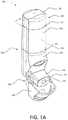
- FIG. 1Ais a perspective view of an example inhaler with an electronics module.
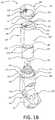
- FIG. 1Bshows a partially-exploded view of an example inhaler with an electronics module.
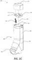
- FIG. 1Cshows a partially-exploded view of an example inhaler with an electronics module.
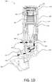
- FIG. 1Dshows a cross-section view of an example inhaler with an electronics module.
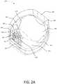
- FIG. 2Adepicts an example electronics module for an inhaler.
- FIG. 2Bshows a partially-exploded view of an example electronics module for an inhaler.
- FIG. 3depicts an example slider of an electronics module for an inhaler.
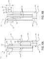
- FIGS. 4A-Bshow projection views of an example slider of an electronics module for an inhaler.
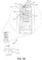
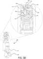
- FIGS. 5A-Dillustrate operation of an example slider in an inhaler.
- FIG. 6illustrates an example mouthpiece of an inhaler having a plurality of bypass ports.
- the present disclosuredescribes devices, systems, and methods for incorporating electronics with a drug delivery device and for sensing, tracking and/or processing usage conditions and parameters associated with the device.
- the devices, systems and methodsare described in the context of a breath-actuated, dry powder inhaler (DPI).
- DPIdry powder inhaler
- the described solutionsare equally applicable to other drug delivery devices, such as an injector, a metered-dose inhaler, a nebulizer, a transdermal patch, or an implantable.
- FIGS. 1A-1Dshow various views of an example inhaler 100 with an electronics module 105 .
- FIG. 1Ais a perspective view of the example inhaler 100 .
- the inhaler 100may be any type of respiratory device for delivering a specific amount of aerosolized medicament to a patient's lungs.
- the inhaler 100may include the electronics module 105 to monitor when and how patients are using the inhaler 100 .
- the inhaler 100may include a housing 190 .
- the housing 190may house the mechanical and/or electrical components for facilitating the effective delivery of a medicament.
- the housing 190may include a lower housing 150 and an upper housing 140 .
- the lower housing 150may include a mouthpiece 120 extending therefrom.
- a mouthpiece cover 130may be included for covering the mouthpiece 120 when the inhaler 100 is not in use.
- the mouthpiece cover 130may be attached to the inhaler 100 via a hinge mechanism 160 , which may enable the mouthpiece cover 130 to swing between open and closed positions.
- the hinge mechanism 160may transfer motion of the mouthpiece cover 130 to one or more other parts within the housing 190 of the inhaler 100 . As discussed below, this transfer of motion may be used to effect operation of other aspects of the inhaler 100 , including for example, operation of the electronics module 105 .
- the mouthpiece 120may have a surface 121 .
- the surface 121may define an opening 122 .
- the opening 122may be an opening to a conduit or air flow path 189 (e.g., as shown in FIG. 1D ).
- the surface 121may also define one or more bypass ports (e.g., the bypass ports shown in FIG. 6 and described later herein).
- Bypass portsmay enable air to flow independent of the air flow path such that when a patient breathes-in or inhales, a portion of the air inhaled by the patient is not from the air flow path 189 .
- the bypass portsmay be used to reduce the flow rate dependence of the inhaler 100 and/or to deliver an appropriate dose of medicament at lower flow rates through the air flow path 189 .
- the upper housing 140may interface with the lower housing 150 .
- the upper housing 140 and the lower housing 150may be removably or permanently attached to one another, thereby forming a seal 125 .
- the housing 190may also include the electronics module 105 .
- the electronics module 105may have a cap 110 (e.g., an electronics module cap) that interfaces with the upper housing 140 .
- the cap 110 and the upper housing 140may be removably or permanently attached to one another, thereby forming a seal 127 .
- FIG. 1Bshows a partially exploded view of the inhaler 100 , including the interface between the upper housing 140 and the lower housing 150 .
- the lower housing 150may have a top portion 155 that defines an upper exterior surface 152 .
- the upper exterior surface 152may include a seal 156 , which may be a labyrinth seal.
- the upper exterior surface 152may be received in the upper housing 140 and overlap with at least a portion of a lower interior surface of the upper housing 140 .
- the lower housing 150may define a rim 153 , which may abut a bottom edge 148 of the upper housing 140 when the lower housing 150 and the upper housing 140 are connected to one another.
- the interface between the bottom edge 148 and the rim 153may define the seal 125 (e.g., as shown in FIG. 1A ).
- the lower housing 150may also define one or more recesses 154 , which may be configured to receive respective one or more clips or protrusions (not shown) on the lower interior surface of the upper housing 140 .
- the coupling of the one or more recesses 154 with the one or more clips or protrusionsmay further prevent or inhibit the upper housing 140 from detaching from the lower housing 150 .
- FIG. 1Bfurther depicts the interface between the upper housing 140 and the cap 110 .
- the cap 110may define an inner peripheral surface 112 and an edge 113 , which may be chamfered.
- the cap 110may further include one or more clips or protrusions 114 extending from the inner peripheral surface 112 .
- the upper housing 140may define a top portion 145 having a first cross sectional area and a bottom portion 147 having a second cross sectional area.
- the first cross sectional areamay be less than the second cross sectional area.
- the top portion 145 of the upper housing 140may include an upper exterior surface 142 , which may be configured to be received in the cap 110 and overlap with at least a portion of the inner peripheral surface 112 of the cap 110 .
- the bottom portion 147 of the upper housing 140may define a rim 143 , which may define a transition from the first cross sectional area of the top portion 145 to the second cross section area of the bottom portion 147 .
- the edge 113 of the cap 110may abut the rim 143 when the cap 110 is attached to or installed on the upper housing 140 .
- the interface between the edge 113 and the rim 143may define the seal 127 , as shown in FIG. 1A .
- the top portion 145 of the upper housing 140may define one or more recesses 144 , which may be configured to receive the one or more clips or protrusions 114 on the cap 110 .
- the coupling of the one or more recesses 144 with the one or more clips or protrusions 114may further prevent or inhibit the cap 110 from detaching from the upper housing 140 .
- the upper housing 140may also include a top surface 149 , which may define one or more orifices 146 .
- the one or more orifices 146may accept a slider 116 that may be slidably mounted within the electronics module 105 . It will be appreciated that having more than one orifice 146 may permit the upper housing 140 and/or the cap 110 to be rotated axially 180 degrees without affecting the manner in which they are attached to one another. In other words, the slider 116 may still be received by at least one of the orifices 146 if the upper housing 140 and/or the cap 110 are rotated axially by 180 degrees.
- the inhaler 100may include a yoke 170 , which may be housed within the upper housing 140 .
- the yoke 170may be cylindrical and may define a hollow portion therein.
- the yoke 170may house a bellows (e.g., the bellows 180 shown in FIG. 1D ), for example, within the hollow portion.
- a top surface 172 of the yoke 170may include one or more apertures 174 .
- the yoke 170may be mechanically coupled to the mouthpiece cover 130 such that the yoke 170 may move axially along an axis 176 when the mouthpiece cover 130 is moved between the open and closed positions.
- the yoke 170may be mechanically coupled to the mouthpiece cover 130 via the hinge mechanism 160 .
- the yoke 170may be mechanically coupled to the mouthpiece cover 130 via cam followers 178 that extend within the lower housing 150 on either side of the mouthpiece 120 from the hinge mechanism 160 to a belt 179 that is distal from the hinge mechanism 160 .
- the belt 179may be housed within the lower housing 150 .
- the belt 179may be configured to engage a bottom edge 171 defined by the yoke 170 such that the cam followers 178 are mechanically coupled to the yoke 170 .
- the cam followers 178may be configured to engage respective cams 162 of the hinge mechanism 160 of the mouthpiece cover 130 .
- the cams 162 of the hinge mechanism 160may rotate causing the cam followers 178 to move along the axis 176 such that the yoke 170 may move along the axis 176 in a direction towards the lower housing 150 .
- the movement of the yoke 170 along the axis 176may cause the bellows to compress, resulting in a dose of medicament being transferred to a dose cup (not shown) within the lower housing 150 .
- the electronics module 105may include components for monitoring parameters associated with the usage and operation of the inhaler 100 .
- the electronics module 105may include a pressure sensor (not shown) for sensing pressure changes within the housing 190 (more particularly, within the cap 110 ) resulting from a patient's inhalation or exhalation at the mouthpiece 120 .
- a negative change in pressuremay be indicative of an inhalation while a positive change in pressure may be indicative of an exhalation.
- the electronics module 105may correlate the measured pressure changes with an air flow rate through the air flow path 189 .
- the electronics module 105may determine an air flow rate resulting from a patient's inhalation or exhalation at the mouthpiece 120 .
- the determined air flow ratemay represent an average air flow rate over the duration of the inhalation or exhalation.
- the determined air flow ratemay also represent a peak air flow rate.
- the determined air flow ratemay be indicative of the quality of the patient's inhalation. That is, a higher flow rate may be generally associated with a stronger inhalation, which may increase the likelihood that a full dose of medicament will be delivered to the patient's lungs. Conversely, a lower flow rate may be generally associated with a weaker inhalation, which may decrease the likelihood that a full dose of medicament will be delivered to the patient's lungs. Accordingly, by determining and tracking the air flow rate through the air flow path 189 during each use of the inhaler 100 , the electronics module 105 may be configured to generate adherence and compliance data that may be useful to patients and other third parties, such as healthcare providers.
- the seal 127(e.g., mechanical interface) between the cap 110 and the upper housing 140 may be configured to enable the electronics module 105 to properly measure and/or sense inhaler operation properties and/or statistics.
- a length of the overlap between the upper exterior surface 142 of the upper housing 140 and the inner peripheral surface 112 of the cap 110may be configured such that a sufficient air seal is maintained at the seal 127 between the cap 110 and the upper housing 140 .
- the air sealmay be sufficient to permit a pressure sensor in the electronics module 105 to sense pressure changes within the housing 190 (more particularly, within the cap 110 ) resulting from a patient's inhalation at the opening 122 of the mouthpiece 120 and to enable the electronics module 105 to properly correlate such pressure changes with an air flow rate through air flow path 189 of the inhaler 100 . If the seal 127 is poor and an excessive amount of ambient air is allowed to enter the through the seal 127 , the inhalation at the opening 122 may result in a lower-than-expected pressure change. Accordingly, in such cases, any pressure change detected by the pressure sensor may not accurately reflect the actual air flow rate through the air flow path 189 .
- FIG. 1Cdepicts another partially exploded view of the inhaler 100 .
- the cap 110 of the electronics module 105may house a printed circuit board (PCB) 118 , which may have an edge 117 that defines a notch 119 .
- the PCB 118may be attached to the cap 110 via a plurality of heat stakes, as further described herein.
- the heat stakesmay be configured to retain the PCB 118 within the cap 110 and/or meet a drop test requirement without the use of fasteners, for example.
- the slider 116may mechanically couple the PCB 118 to the operation of the mouthpiece cover 130 .
- the slider 116may move axially to activate a switch (e.g., the switch 222 shown in FIGS. 2A and 2B ) on the PCB 118 when the mouthpiece cover 130 is opened to expose the mouthpiece 120 .
- a switche.g., the switch 222 shown in FIGS. 2A and 2B
- a first (e.g., upper) portion of the slider 116may protrude through the notch 119 .
- a second (lower) portion of the slider 116may protrude through one of the orifices 146 and extend into the upper housing 140 .
- a slider springe.g., the slider spring 260 shown in FIG. 2B
- the slider springmay bias the slider 116 in a downward direction, i.e., push the slider towards the lower housing 150 .
- the slider springmay cause the end of the slider 116 within the upper housing 140 to maintain contact with, and continually rest against, the top surface 172 of the yoke 170 .
- the slider 116may move axially with the yoke 170 along the axis 176 when the mouthpiece cover 130 is moved between the open and closed positions.
- FIG. 1Dis a cross-sectional view of the inhaler 100 .
- the inhaler 100may have an activation spring 182 disposed in the upper housing 140 and a bellows 180 disposed within the yoke 170 .
- the activation spring 182may bias the yoke 170 against the bellows 180 .
- the yoke 170may move axially in a direction towards the lower housing 150 .
- the bias against the yoke 170 from the activation spring 182may cause the bellows 180 to compress, thereby resulting in a dose of medicament being transferred from a reservoir 184 to a dose cup 186 in the lower housing 150 .
- the inhaler 100may be a breath-actuated DPI.
- the inhaler 100may include a deagglomerator 187 , which may be configured to aerosolize the dose of medicament by breaking down the agglomerates of the medicament in the dose cup 186 when the air flow through the air flow path 189 meets or exceeds a particular rate, or is within a specific range.
- the dose of medicamentmay be delivered orally to a patient via the air flow path 189 extending through the mouthpiece 120 .
- the air flow path 189may be a medicament delivery air flow path that extends from the opening 122 on the mouthpiece 120 through the deagglomerator 187 and through a vent 188 on the lower housing 150 .
- the vent 188may serve as the inlet for air flow path 189 .
- the opening 122 on the mouthpiece 120may serve as the outlet for the air flow path 189 .
- the medicamentmay be introduced into the air flow path 189 when the patient breathes-in or inhales. For example, when the patient breathes-in or inhales from the mouthpiece 120 , air is pulled through the vent 188 to the deagglomerator 187 . The air is then pulled through the deagglomerator 187 where the air mixes with the medicament.
- the air-medicament mixturemay exit the inhaler 100 via the opening 122 of the mouthpiece 120 .
- the seal 127 between the cap 110 and the upper housing 140may be configured such that medication delivery is not adversely affected.
- the deagglomerator 187may be configured to aerosolize a dose of medicament from the reservoir 184 when the air flow rate via the air flow path 189 reaches or exceeds 30 LPM or, more preferably, when the air flow rate reaches or exceeds 45 LPM.
- the inhaler 100may be configured to yield a particular air flow rate through the air flow path 189 when a certain pressure is applied at the opening 122 of the mouthpiece 120 . The relationship between the air flow rate and applied pressure may change if there are undesirable gaps or openings in the housing 190 .
- a higher pressuree.g., a stronger inhalation
- the air flow resistance associated with the air flow path 189has changed (e.g., decreased) due to excessive ambient air entering the housing 190 through the seal 127 .
- This increased pressuremay be beyond the physical capabilities of patients with limited lung function. Accordingly, the sufficiency of the seal 127 between the upper housing 140 and the cap 110 may affect the ability of the inhaler 100 to deliver a proper dose of medicament.
- the mechanical interface between the cap 110 and the upper housing 140may be configured such that, at a given pressure applied at the opening 122 , the air flow rate through the air flow path 189 of the inhaler 100 may be substantially similar to the air flow rate through the air flow path 189 of an inhaler 100 without the electronics module 105 and/or where the top portion 145 of the upper housing 140 does not include any openings, such as orifices 146 ).
- the air flow ratesmay be within 2% of one another.
- a suitable air flow resistance associated with the air flow path 189 of the inhaler 100may fall within the range of 0.020 kilopascal per liters per minute (kPa 0.5 /LPM) to 0.042 kPa 0.5 /LPM. More preferably, the air flow resistance associated with the air flow path 189 of the inhaler 100 may fall within the range of 0.025 kPa 0.5 /LPM to 0.037 kPa 0.5 /LPM. Even more preferably, the air flow resistance associated with the air flow path 189 of the inhaler 100 may fall within the range of 0.028 kPa 0.5 /LPM to 0.034 kPa 0.5 /LPM.
- a suitable air flow rate associated with the air flow path 189 of the inhaler 100may fall within the range of 50 LPM to 80 LPM when a pressure drop of 4.0 kPa is applied across the air flow path 189 . More preferably, the air flow rate associated with the air flow path 189 of the inhaler 100 may fall within a range of 55 LPM to 75 LPM when a pressure drop of 4.0 kPa is applied across the air flow path 189 . Even more preferably, the air flow rate associated with the air flow path 189 of the inhaler 100 may fall within a range of 59 LPM to 71 LPM when a pressure drop of 4.0 kPa is applied across the air flow path 189 .
- FIG. 2Adepicts the exemplary electronics module 105 for the inhaler 100 .
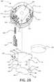
- FIG. 2Bshows a partially-exploded view of the exemplary electronics module 105 for the inhaler 100 .
- the electronics module 105may include a cap 110 , a PCB 118 , a battery 230 , a battery holder 240 , and a slider 116 .
- the PCB 118may be mounted within the cap 110 .
- Respiratory devicessuch as the inhaler 100 may be required to successfully pass a drop test.
- the drop testmay involve dropping the respiratory device from a predetermined height to assess the extent to which the device's operation and/or performance are adversely impacted.
- Fastening the PCB 118 to the cap 110 using fastenersmay result in failure of the drop test.
- the operation and/or performance of the inhaler 100may be adversely impacted when the PCB 118 is attached to the cap 110 using fasteners.
- Using fasteners to fasten the PCB 118 to the cap 110may also increase manufacturing cost and/or manufacturing time.
- the cap 110may include a plurality of heat stakes, such as heat stakes 212 , 214 .
- the heat stakes 212 , 214may be configured to secure the PCB 118 to the cap 110 , for example, without the use of fasteners.
- the heat stakes 212 , 214may protrude or extend from a top inner surface 220 of the cap 110 .
- the heat stakes 212may have a circular cross section.
- the heat stakes 212may have a diameter that is smaller than a standard heat stake diameter. That is, the diameter of the heat stakes 212 may be selected such that the inhaler 100 will successfully pass the drop test without taking up too much space on the PCB 118 .
- the heat stakes 212may have a diameter less than 1.4 mm.
- the PCB 118may have a plurality of openings 224 , 226 , 228 , as shown in FIG. 2B .
- One or more of the openingsmay correspond to the heat stakes 212 such that the heat stakes 212 may be adapted to protrude through the PCB 118 via the openings 226 when the PCB 118 is mounted within the cap 110 .
- the heat stake 214may have a non-circular cross-section, for example, such as a rib-shaped cross-section.
- the plurality of openings on the PCB 118may include a notch 224 that corresponds to the location of the heat stake 214 , for example.
- the PCB 118may define the notch 224 such that the heat stake 214 may be adapted to protrude through the PCB 118 via the notch 224 when the PCB 118 is mounted within the cap 110 .
- Each of the heat stakes 212 and the heat stake 214may define a distal end that is opposite from the top inner surface 220 of the cap 110 .
- the distal end of each of the heat stakes 212 and the heat stake 214may be configured to be partially deformed when heated to a predetermined temperature. The partially deformed heat stakes 212 and heat stake 214 may secure the PCB 118 to the cap 110 .
- the PCB 118may include a switch 222 , which may be a toggle switch or a detector switch.
- the arm of a detector switchmay have a range of motion, or larger tolerance, than the range of motion on a toggle switch. As such, a detector switch may have a lower risk of damage when engaged/disengaged by the slider 116 .
- the switch 222may provide a wake signal to the electronics module 105 , for example, when activated.
- the wake signalmay transition the electronics module 105 from a first operational state to a second operational state.
- the first operational statemay be an off state or a sleep state.
- the second operational statemay be an active (e.g., on) state.
- the electronics module 105may include an adapter device to mechanically engage the switch 222 as the mouthpiece cover 130 is opened and/or closed.
- the slider 116may be configured to activate the switch 222 .
- the switch 222may be located adjacent to the notch 119 , for example, such that the slider 116 activates and deactivates the switch 222 as it moves axially. As described herein, the slider 116 may move axially when the mouthpiece cover 130 is opened and closed.
- the cap 110may include a slider guide 216 .
- the slider guide 216may protrude from the top inner surface 220 of the cap 110 .
- the slider guide 216may be configured to accept the slider 116 such that the slider is slidably mounted within the cap 110 .
- the slider guide 216may be configured to accept a portion of the slider 116 .
- the slider guide 216may define a stopper 217 .
- the stopper 217may be configured to retain the slider 116 within the slider guide 216 .
- the stopper 217may be further configured to limit an axial travel of the slider 116 , for example, when the mouthpiece cover 130 is opened and/or closed.
- the cap 110may define a plurality of datum ribs 211 .
- the datum ribs 211may be configured to support the PCB 118 .
- the datum ribs 211may be configured to locate the PCB 118 a predetermined distance from the top inner surface 220 of the cap 110 .
- the datum ribs 211may be any shape and may be configured to allow for clearance of electrical components mounted to the PCB 118 .
- the cap 110may define a plurality of recesses 213 .
- the recesses 213may be cavities in the top inner surface 220 of the cap 110 .
- the recesses 213may be configured to allow for clearance of one or more electrical components mounted to the PCB 118 .
- the recesses 213may accept respective portions of the one or more electrical components mounted to the PCB 118 .
- the PCB 118may further include a processor and a transmitter.
- the PCB 118may be installed towards the end of manufacture of the inhaler (e.g., following equilibration of the inhaler). Installing the PCB 118 towards the end of the manufacture of the inhaler 100 may be advantageous since equilibration of the inhaler 100 may damage the sensitive electronics on the PCB 118 . Equilibration may involve filing the inhaler 100 with a medicament and storing the inhaler 100 at a predefined temperature and humidity for duration of time (e.g., four weeks) before final packing of the inhaler 100 .
- the battery holder 240may be a through hole type battery holder.
- the battery holder 240may define a base 242 and two legs 244 .
- the length of the legs 244may be configured such that the battery holder 240 can accept the battery 230 .
- the base 242may include a curved edge 246 .
- the curved edge 246may be configured to allow access to the battery 230 .
- the battery holder 240may have tabs 248 that extend from the legs 244 .
- the tabs 248may extend from the legs 244 substantially perpendicular to the base 242 .
- the tabs 248may be configured to attach the battery holder 240 to the PCB 118 .
- the tabs 248may extend through openings 228 defined by the PCB 118 .
- the tabs 248may be compliant such that the tabs deflect and engage the openings 228 such that the battery holder 240 is removably attached to the PCB 118 .
- the battery holder 240may be configured such that the battery 230 maintains contact with the PCB 118 .
- the battery holder 240may be secured to the PCB 118 .
- the battery holder 240may be configured such that an electrical connection may be formed between the PCB 118 and the battery 230 (e.g., such as a coin cell).
- One or more components of the PCB 118may be selectively activated based on a position of the mouthpiece cover 130 . For example, activation of the switch 222 (e.g., or activation of some other switching means, such as an optical sensor, an accelerometer, or a Hall effect sensor) may wake a processor and/or transmitter from an off state (or a power-conserving sleep mode) to an on state (or an active mode). Conversely, deactivation of the switch 222 may transition the processor and/or transmitter from the on state (or active mode) to an off state or a lower power mode.
- activation of the switch 222e.g., or activation
- the PCB 118may include a sensor (not shown) that may provide information to the processor about a patient's inhalation.
- the sensormay be a pressure sensor, such as a MEMS or NEMS pressure sensor (e.g., a barometric pressure sensor, a differential pressure sensor, etc.).
- the sensormay provide the information for example, using a pressure change and/or a pressure difference.
- the sensormay provide an instantaneous pressure reading to the processor and/or aggregated pressure readings over time.
- the processormay use the information to determine an air flow rate associated with the patient's inhalation through the air flow path 189 .
- the processormay also use the information to determine the direction of air flow. That is, a negative change in air pressure through the air flow path 189 may indicate that the patient has inhaled from the mouthpiece 120 while a positive change in air pressure through the air flow path 189 may indicate that the patient has exhaled into the mouthpiece 120 .
- the electronics module 105may further include a wireless communication circuit, such as a Bluetooth chipset (e.g., a Bluetooth Low Energy chipset). As such, the electronics module 105 may provide a pressure measurement to an external device (e.g., a smartphone), which may perform additional calculations on the pressure measurement data, provide feedback to the user, and/or the like.
- the electronics module 105may include a control circuit, which for example, may be part of the communication circuit.
- the electronics module 105may determine whether the mouthpiece cover 130 has been open or closed and whether a received pressure measurement exceeds a threshold or is within a specific pressure range, which may be indicative of whether the medication inhaled by a user has reached a predetermined or prescribed level.
- the pressure measurement threshold(s) and/or range(s)may be stored in a memory of the electronics module 105 .
- the electronics module 105may determine the state of the inhaler 100 and may generate a signal that indicates the state of the inhaler 100 .
- the electronics module 105may include a memory (not shown) for storing data collected by the sensor (e.g., pressure measurements) and/or data generated by the processor (e.g., air flow rates). The stored data may be accessed by the processor and wirelessly communicated to an external device, such as a smartphone, via the wireless communication circuit.
- the memorymay be non-removable memory and/or removable memory.
- the non-removable memorymay include random-access memory (RAM), read-only memory (ROM), a hard disk, or any other type of memory storage device.
- the removable memorymay include a subscriber identity module (SIM) card, a memory stick, a secure digital (SD) memory card, and the like.
- SIMsubscriber identity module
- SDsecure digital
- the processor of the electronics module 105may comprise a microcontroller, a programmable logic device (PLD), a microprocessor, an application specific integrated circuit (ASIC), a field-programmable gate array (FPGA), or any suitable processing device, controller, or control circuit.
- the processormay comprise an internal memory.
- the processor of the electronics module 105may receive power from the battery 230 , and may be configured to distribute and/or control the power to the other components in the electronics module 105 .
- the battery 230may be any suitable device for powering the electronics module 105 .
- the battery 230may be directly connected to one or more of the sensor, the memory, and/or the transceiver of the electronics module 105 .
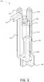
- FIG. 3illustrates the example slider 116 for the inhaler 100 .
- the slider 116may be mechanically coupled to the mouthpiece cover 130 of the inhaler such that the slider 116 engages a switch 222 in the electronics module 105 as the mouthpiece cover 130 is opened and/or closed.
- the slider 116may include a distal end 302 (e.g., a base).
- the slider 116may include an arm 304 .
- the arm 304may extend from the distal end 302 .
- the arm 304may define a clip 306 .
- the clip 306may be an enlarged section of the arm 304 .
- the clip 306may be configured to engage the stopper 217 , shown in FIGS. 2A and 2B .
- the arm 304may be compliant about its connection with the slider 116 .
- the arm 304may be configured to flex towards and/or away from the slider 116 in response to an applied force.
- the clip 306may have an inclined surface such that the arm 304 flexes away from the slider 116 (e.g., until the clip 306 engages the stopper 217 ) when the slider 116 is pressed into the slider guide 216 , shown in FIGS. 2A and 2B .
- the slider 116may define a spring seat 312 .
- the spring seat 312may be an upper horizontal surface of the slider 116 .
- a spring cruciform 314may extend from the spring seat 312 .
- the spring cruciform 314may be configured to extend within and captively engage a slider spring 260 (shown in FIG. 2B ).
- the slider 116may define one or more ribs 316 .
- the ribs 316may define one or more fingers 308 , 310 that extend beyond the spring cruciform 314 .
- the finger 308may be configured to engage the switch 222 of the inhaler 100 .
- the finger 308may include a horizontal extension 311 .
- the horizontal extension 311may extend in a direction opposite the spring cruciform 314 .
- One or more fingers 310may be configured to limit vertical travel of the slider 116 .
- the fingers 310may abut a surface in the slider guide 216 (shown in FIGS. 2A and 2B
- FIGS. 4A-4Bare projection views of the example slider 116 .
- the ribs 316may be rectangular protrusions that extend along the length of the slider 116 .
- the ribs 316may be configured to engage (e.g., abut) inside surfaces of the slider guide 216 such that the slider 116 remains aligned within the slider guide 216 .
- the slider 116may define an intermediate surface 303 .
- the ribs 316may extend from the intermediate surface 303 .
- Each of the ribs 316may include one of fingers 308 , 310 .
- one of the ribs 316may define the finger 308 .
- the distal end 302 of the slider 116may be offset from the finger 308 .
- the finger 308may define a centerline 309 .
- the distal end 302 of the slider 116may be offset a distance D 1 from the centerline 309 .
- the distal end 302 of the slider 116may extend from the intermediate surface 303 .
- the distal end 302 of the slider 116may define a bottom surface 301 .
- the bottom surface 301may be configured to abut the yoke 170 of the inhaler 100 .
- the bottom surface 301may extend a distance D 2 from the intermediate surface 303 .
- the distance D 2may be about 2.0 mm (e.g., 2.0 mm with a manufacturing tolerance of approximately +/ ⁇ 0.1 mm).
- the slider 116may define a spring seat 312 and a spring cruciform 314 .
- the spring cruciform 314may extend a distance D 3 from the spring seat 312 .
- the distance D 3may be about 1.5 mm (e.g., 1.5 mm with a manufacturing tolerance of approximately +/ ⁇ 0.1 mm).
- the arm 304 of the slider 116may include a clip 306 .
- the clip 306may be an enlarged section of the arm 304 that is configured as a stopping mechanism.
- the clip 306may define a stopper surface 305 .
- the stopper surface 305may be configured to abut a stopper, such as the stopper 217 of the slider guide 216 of the cap 110 , as shown in FIGS. 2A and 2B .
- the finger 308may include a horizontal extension 311 that may extend orthogonally from the corresponding rib of the ribs 316 .
- the horizontal extension 311may extend a distance D 4 from the corresponding rib of the ribs 316 .
- the distance D 4may be configured such that the horizontal extension 311 engages the switch 222 of the PCB 118 (e.g., as shown in FIGS. 5A-5D ) without obstructing the travel of the slider 116 .
- the distance D 4may be about 2.30 mm (e.g., 2.30 mm with a manufacturing tolerance of approximately +/ ⁇ 0.07 mm).
- the finger 308may define a top surface 307 .
- the top surface 307may be defined by the horizontal extension 311 .
- the stopper surface 305may be a distance D 5 from the top surface 307 .
- the distance D 5may be configured to limit the vertical travel of the slider 116 within the slider guide 216 .
- the distance D 5may be configured to limit the vertical travel of the slider 116 after the slider 116 activates the switch 222 on the PCB 118 of the electronics module 105 .
- the distance D 5may be about 7.22 mm (e.g., 7.22 mm with a manufacturing tolerance of approximately +/ ⁇ 0.09 mm).
- the top surface 307may be a distance D 6 from the spring seat 312 .
- the distance D 6may be about 3.52 mm (e.g., 3.52 mm with a manufacturing tolerance of approximately +/ ⁇ 0.1 mm).
- the slider 116may define one or more second fingers 310 .
- one or more of the ribs 316may define the second fingers 310 .
- the second fingers 310may extend a distance D 7 from the spring seat 312 .
- the distance D 7may be about 3.12 mm (e.g., 3.12 mm with a manufacturing tolerance of approximately +/ ⁇ 0.1 mm).
- FIGS. 5A-5Dillustrate operation of the slider 116 of the example inhaler 100 as the mouthpiece cover 130 is operated from a closed position to an open position (e.g., a partially open position).
- movement of the mouthpiece cover 130 from the closed position to the open positionmay cause the slider 116 to travel axially, in a downward direction towards the mouthpiece 120 .
- a portion of the slider 116may physically engage with, and thus activate, the switch 222 .
- movement of the mouthpiece cover 130 from the open position to the closed positionmay cause the slider 116 to travel in an upward direction towards the cap 110 .
- the portion of the slider 116may physically disengage with, and thus deactivate, the switch 222 .
- the yoke 170may be configured to move up and down within the upper housing 140 of the inhaler 100 when the mouthpiece cover 130 is opened and closed.
- the slider 116may be operably coupled to the mouthpiece cover 130 via the yoke 170 .
- the up and down movement of the yoke 170may cause the slider 116 to activate and/or deactivate, respectively, the switch 222 .
- the mouthpiece cover 130is illustrated in four positions, a closed position in FIG. 5A , a first position in FIG. 5B , a second position in FIG. 5C , and a third position in FIG. 5D .
- the mouthpiece cover 130may transition between any number of distinct positions as the mouthpiece cover 130 is transitioned from the closed position to a fully open position, and vice versa.
- the slider 116may be in an intermediate position when the mouthpiece cover 130 is in the closed position.
- the horizontal extension 311 of the slider 116may be located between the top inner surface 220 of the cap 110 and the switch 222 .
- the slider spring 260may be partially compressed when the slider 116 is in the intermediate position.
- the distal end 302 of the slider 116may be in contact with the top surface 172 of the yoke 170 .
- the mouthpiece cover 130may be opened to the first position.
- the first positionmay be a partially open position such that a portion of the mouthpiece 120 is exposed.
- the slider 116may be in an upper position such that the horizontal extension 311 of the slider 116 may be closer to the top inner surface 220 of the cap 110 when the mouthpiece cover 130 is in the first position.
- the horizontal extension 311may be in contact with the top inner surface 220 .
- the slider spring 260may be further compressed beyond the partially compressed position associated with the intermediate position of the slider 116 .
- the distal end 302 of the slider 116may remain in contact with the top surface 172 of the yoke 170 .
- the mouthpiece cover 130may be opened to the second position.
- the second positionmay be a partially open position such that the mouthpiece 120 is more exposed than in the first position.
- the mouthpiece cover 130is more open in the second position than in the first position.
- the slider 116may be in a contact position such that the horizontal extension 311 of the slider 116 is in contact with the switch 222 when the mouthpiece cover 130 is in the second position.
- the switch 222may be activated when the slider 116 is in the contact position.
- the distal end 302 of the slider 116may remain in contact with the top surface 172 of the yoke 170 .
- the mouthpiece cover 130may be opened to the third position.
- the third positionmay be a partially open position such that the mouthpiece 120 is more exposed than in the second position.
- the mouthpiece cover 130is more open in the third position than in the second position.
- the horizontal extension 311 of the slider 116may remain in contact with the switch 222 when the mouthpiece cover 130 is in the third position.
- the horizontal extension 311 of the slider 116may activate the switch 222 to a maximum switch travel angle when the mouthpiece cover 130 is in the third position.
- the distal end 302 of the slider 116may remain in contact with the top surface 172 of the yoke 170 .
- FIG. 6illustrates an example mouthpiece 620 of an inhaler 600 (e.g., such as the example inhaler 100 ).
- the example mouthpiece 620may be an alternate mouthpiece having a plurality of (e.g., four) bypass ports 623 , 624 , 625 , 626 .
- the bypass ports 623 , 624 , 625 , 626may enable air to flow independent of an air flow path (e.g., such as the air flow path 189 shown in FIG. 1D ) such that when a patient breathes-in or inhales through the mouthpiece 620 a portion of the air inhaled by the patient from the air flow path and another portion of the air inhaled by the patient is not from the air flow path.
- an air flow pathe.g., such as the air flow path 189 shown in FIG. 1D
- bypass ports 623 , 624 , 625 , 626may extend through the mouthpiece 120 , exterior to the air flow path, from a front surface 621 of the mouthpiece 620 to a rear surface (not shown) of the mouthpiece 620 .
- the bypass ports 623 , 624 , 625 , 626may reduce the flow rate through the air flow path to reduce the flow rate dependence of the inhaler 100 and/or to deliver an appropriate dose of medicament at lower flow rates through the air flow path 189 .
- the mouthpiece 620may have a front surface 621 that defines a flow path opening 622 and the plurality of bypass ports 623 , 624 , 625 , 626 .
- the flow path opening 622may be the entrance and/or exit conduit for the air flow path of the inhaler 600 .
- the air flow pathmay be a breath-actuated air flow path for entraining a dry powder medicament from the inhaler 600 that begins at a vent 610 and ends at the flow path opening 622 .
- the bypass ports 623 , 624 , 625 , 626may be configured to allow air to flow independently of the air flow path from a region exterior to the mouthpiece 620 to the front surface 621 when a breath induced low pressure is applied to the front surface 621 .
- the bypass ports 623 , 624 , 625 , 626may reduce the linear flow rate of air through the air flow path and the flow path opening 622 .
- a reduced linear flow rate of air through the flow path opening 622may reduce fluctuations in the velocity of the air flowing through the air flow path, for example, as a result of changes in breath induced low pressure. That is, the bypass ports 623 , 624 , 625 , 626 may reduce the flow rate dependence of a delivered fine particle dose, e.g., the mass of the active substance below 5 ⁇ m.
- the delivered fine particle dosecan be measured according to s. 2.9.18. of the European Pharmacopoeia 6.0 using an Anderson Cascade Impactor.
- bypass ports 623 , 624 , 625 , 626may reduce the formation of secondary vortices, stalled airflow within a swirl chamber of the airflow path, and/or areas of high sheer on the walls of the swirl chamber, all of which can adversely affect the performance of the inhaler 600 .
- a ratio of the sum of the bypass ports 623 , 624 , 625 , 626 cross-sectional area to the flow path opening 622 cross-sectional areamay be configured such that that when a pressure breath induced low pressure is applied to the front surface 621 of the mouthpiece 620 at least about 5%, preferably at least about 15%, more preferably from about 5% to about 50%, more preferably from about 15% to about 40%, and even more preferably from about 20% to about 30% of the resulting air flow is directed through the bypass ports 623 , 624 , 625 , 626 .
- the sum of the cross-sectional areas of the bypass ports 623 , 624 , 625 , 626may be from about 0.75 mm 2 to about 20 mm 2 , more preferably from about 5 mm 2 to about 16 mm 2 , and even more preferably from about 9 mm 2 to about 11 mm 2 .
- the flow path opening 622may have a cross-sectional area of from about 25 mm 2 to about 50 mm 2 , preferably from about 30 mm 2 to about 45 mm 2 , and more preferably from about 35 mm 2 to about 45 mm 2 .
- a suitable air flow resistance associated with the air flow path 189 of the inhaler 600 with the electronics module and the bypass ports 623 , 624 , 625 , 626may fall within the range of 0.015 kPa 0.5 /LPM to 0.031 kPa 0.5 /LPM. More preferably, the air flow resistance associated with the air flow path 189 of the inhaler 600 with the electronics module and the bypass ports 623 , 624 , 625 , 626 may fall within the range of 0.018 kPa 0.5 /LPM to 0.028 kPa 0.5 /LPM.
- the air flow resistance associated with the air flow path 189 of the inhaler 600 with the electronics module and the bypass ports 623 , 624 , 625 , 626may fall within the range of 0.021 kPa 0.5 /LPM to 0.025 kPa 0.5 /LPM.
- a suitable air flow rate associated with the air flow path 189 of the inhaler 600 with the electronics module and the bypass ports 623 , 624 , 625 , 626may fall within the range of 70 LPM to 105 LPM when a pressure drop of 4.0 kPa is applied across the air flow path 189 of the inhaler 600 . More preferably, the air flow rate associated with the air flow path 189 of the inhaler 600 with the electronics module and the bypass ports 623 , 624 , 625 , 626 may fall within the range of 75 LPM to 100 LPM when a pressure drop of 4.0 kPa is applied across the air flow path 189 .
- the air flow rate associated with the air flow path 189 of the inhaler 600 with the electronics module and the bypass ports 623 , 624 , 625 , 626may fall within the range of 80 LPM to 95 LPM when a pressure drop of 4.0 kPa is applied across the air flow path 189 .
Landscapes
- Health & Medical Sciences (AREA)
- Engineering & Computer Science (AREA)
- Life Sciences & Earth Sciences (AREA)
- General Health & Medical Sciences (AREA)
- Animal Behavior & Ethology (AREA)
- Biomedical Technology (AREA)
- Heart & Thoracic Surgery (AREA)
- Veterinary Medicine (AREA)
- Public Health (AREA)
- Pulmonology (AREA)
- Bioinformatics & Cheminformatics (AREA)
- Anesthesiology (AREA)
- Hematology (AREA)
- Biophysics (AREA)
- Physics & Mathematics (AREA)
- Pathology (AREA)
- Medical Informatics (AREA)
- Molecular Biology (AREA)
- Surgery (AREA)
- Infusion, Injection, And Reservoir Apparatuses (AREA)
- Catching Or Destruction (AREA)
- Packages (AREA)
Abstract
Description
Claims (26)
Priority Applications (3)
| Application Number | Priority Date | Filing Date | Title |
|---|---|---|---|
| US15/704,444US11000653B2 (en) | 2016-11-18 | 2017-09-14 | Inhaler |
| US17/223,873US20210220579A1 (en) | 2016-11-18 | 2021-04-06 | Inhaler |
| US18/740,754US20240390609A1 (en) | 2016-11-18 | 2024-06-12 | Inhaler |
Applications Claiming Priority (2)
| Application Number | Priority Date | Filing Date | Title |
|---|---|---|---|
| US201662424299P | 2016-11-18 | 2016-11-18 | |
| US15/704,444US11000653B2 (en) | 2016-11-18 | 2017-09-14 | Inhaler |
Related Child Applications (1)
| Application Number | Title | Priority Date | Filing Date |
|---|---|---|---|
| US17/223,873ContinuationUS20210220579A1 (en) | 2016-11-18 | 2021-04-06 | Inhaler |
Publications (2)
| Publication Number | Publication Date |
|---|---|
| US20180140788A1 US20180140788A1 (en) | 2018-05-24 |
| US11000653B2true US11000653B2 (en) | 2021-05-11 |
Family
ID=60452683
Family Applications (3)
| Application Number | Title | Priority Date | Filing Date |
|---|---|---|---|
| US15/704,444Active2038-12-18US11000653B2 (en) | 2016-11-18 | 2017-09-14 | Inhaler |
| US17/223,873AbandonedUS20210220579A1 (en) | 2016-11-18 | 2021-04-06 | Inhaler |
| US18/740,754PendingUS20240390609A1 (en) | 2016-11-18 | 2024-06-12 | Inhaler |
Family Applications After (2)
| Application Number | Title | Priority Date | Filing Date |
|---|---|---|---|
| US17/223,873AbandonedUS20210220579A1 (en) | 2016-11-18 | 2021-04-06 | Inhaler |
| US18/740,754PendingUS20240390609A1 (en) | 2016-11-18 | 2024-06-12 | Inhaler |
Country Status (11)
| Country | Link |
|---|---|
| US (3) | US11000653B2 (en) |
| EP (2) | EP3506971B1 (en) |
| JP (2) | JP7014791B2 (en) |
| KR (1) | KR102491841B1 (en) |
| CN (2) | CN114159656A (en) |
| AU (1) | AU2017359597B2 (en) |
| CA (1) | CA3043987A1 (en) |
| EA (1) | EA039125B1 (en) |
| ES (1) | ES2811842T3 (en) |
| IL (2) | IL266617B2 (en) |
| WO (1) | WO2018091957A1 (en) |
Cited By (4)
| Publication number | Priority date | Publication date | Assignee | Title |
|---|---|---|---|---|
| US20210220579A1 (en)* | 2016-11-18 | 2021-07-22 | Norton (Waterford) Limited | Inhaler |
| US20220218920A1 (en)* | 2019-05-01 | 2022-07-14 | Norton (Waterford) Limited | Electronic module for medical device |
| US20230016850A1 (en)* | 2019-11-28 | 2023-01-19 | Chiesi Farmaceutici S.P.A. | Powder inhaler assembly |
| WO2023094551A1 (en) | 2021-11-24 | 2023-06-01 | Norton (Waterford) Limited | Drug delivery device with electronics |
Families Citing this family (13)
| Publication number | Priority date | Publication date | Assignee | Title |
|---|---|---|---|---|
| USD296605S (en)* | 1985-01-31 | 1988-07-12 | Ecotat System Company | Combination outer garment and tent |
| US9022980B2 (en)* | 2005-02-01 | 2015-05-05 | Kaleo, Inc. | Medical injector simulation device |
| CA3046354A1 (en)* | 2017-01-17 | 2018-07-26 | Kaleo, Inc. | Medicament delivery devices with wireless connectivity and event detection |
| USD914193S1 (en)* | 2018-03-30 | 2021-03-23 | Nick Mariani | Inhaler |
| US11929160B2 (en) | 2018-07-16 | 2024-03-12 | Kaleo, Inc. | Medicament delivery devices with wireless connectivity and compliance detection |
| PL3861601T3 (en) | 2018-10-11 | 2024-06-10 | Bruin Biometrics, Llc | DEVICE WITH A SINGLE-USE ELEMENT |
| USD960349S1 (en) | 2019-02-04 | 2022-08-09 | Orion Corporation | Inhaler |
| CA3140949A1 (en) | 2019-05-17 | 2020-11-26 | Norton (Waterford) Limited | Drug delivery device with electronics |
| USD877322S1 (en)* | 2019-08-03 | 2020-03-03 | Optimist Inhaler, LLC | Flip-top metered-dose inhaler |
| MX2022006099A (en)* | 2019-11-28 | 2022-06-14 | Chiesi Farm Spa | Electronic module for an inhaler and inhaler assembly comprising the electronic module. |
| USD983961S1 (en)* | 2020-02-14 | 2023-04-18 | Aptar France Sas | Inhaler |
| USD995752S1 (en)* | 2020-02-14 | 2023-08-15 | Aptar France Sas | Inhaler |
| USD989944S1 (en)* | 2021-11-19 | 2023-06-20 | Sandra Dyer | Inhaler device |
Citations (120)
| Publication number | Priority date | Publication date | Assignee | Title |
|---|---|---|---|---|
| US5069204A (en)* | 1989-08-23 | 1991-12-03 | Riker Laboratories, Inc. | Inhaler |
| WO1995022365A1 (en) | 1994-02-21 | 1995-08-24 | Astra Aktiebolag | Inhalation device with electronically readable identification means |
| US5482030A (en)* | 1994-06-13 | 1996-01-09 | Klein; David | Aerosol and non-aerosol spray counter |
| US5839429A (en) | 1994-03-25 | 1998-11-24 | Astra Aktiebolag | Method and apparatus in connection with an inhaler |
| US5842468A (en) | 1994-10-27 | 1998-12-01 | Medic-Aid Limited | Dosimetric spacer for calculating dosage administered |
| US5887586A (en) | 1994-06-23 | 1999-03-30 | Astra Aktiebolag | Method and system for measuring a dose of drug inhaled |
| WO1999063901A1 (en) | 1998-06-08 | 1999-12-16 | Glaxo Group Limited | Disease management/training system and method |
| US6082358A (en)* | 1998-05-05 | 2000-07-04 | 1263152 Ontario Inc. | Indicating device for aerosol container |
| US6142339A (en)* | 1998-01-16 | 2000-11-07 | 1263152 Ontario Inc. | Aerosol dispensing device |
| US6202642B1 (en) | 1999-04-23 | 2001-03-20 | Medtrac Technologies, Inc. | Electronic monitoring medication apparatus and method |
| US6285731B1 (en) | 1998-03-30 | 2001-09-04 | Astra Aktiebolag | Counting device and inhaler including a counting device |
| US20020047021A1 (en)* | 1998-01-16 | 2002-04-25 | Richard Blacker | Delivery system for a medicament and method for the assembly thereof |
| US6390088B1 (en) | 1993-12-13 | 2002-05-21 | Boehringer Ingelheim Kg | Aerosol inhaler |
| US20020128591A1 (en) | 2000-09-11 | 2002-09-12 | Kleiner Lothar W. | Transdermal electrotransport device and method for manufacturing same |
| US20020185128A1 (en) | 1998-03-30 | 2002-12-12 | Astra Aktiebolag, Swedish Corporation | Electrical device |
| WO2003063754A1 (en) | 2002-01-30 | 2003-08-07 | Glaxo Group Limited | Compliance aid |
| US20030192535A1 (en) | 1999-09-24 | 2003-10-16 | Astrazeneca Ab. | Inhaler |
| US20040089299A1 (en) | 2000-10-20 | 2004-05-13 | Bonney Stanley George | Inhaler |
| US20040117062A1 (en) | 2001-04-02 | 2004-06-17 | Bonney Stanley George | Medicament dispenser |
| US20050119604A1 (en) | 2001-04-02 | 2005-06-02 | Bonney Stanley G. | Medicament dispenser |
| US20050161467A1 (en) | 2002-04-26 | 2005-07-28 | Jones Anthony P. | Medicament dispenser |
| US6958691B1 (en) | 1999-10-01 | 2005-10-25 | Smithkline Beecham Corporation | Medicament delivery system |
| US20050251289A1 (en) | 2002-07-25 | 2005-11-10 | Bonney Stanley G | Medicament dispenser |
| US20050247312A1 (en) | 2002-07-25 | 2005-11-10 | Davies Michael B | Medicament dispenser |
| US20050268905A1 (en)* | 2002-11-04 | 2005-12-08 | Jorgen Rasmussen | Device for dispension |
| US6978780B1 (en) | 1998-03-30 | 2005-12-27 | Astrazeneca Ab | Inhalation device with a dose counting unit |
| US6990975B1 (en) | 1999-03-06 | 2006-01-31 | Smithkline Beecham Corporation | Medicament delivery system |
| US7072738B2 (en) | 2001-04-02 | 2006-07-04 | Glaxo Group Limited | Medicament dispenser |
| EP1135056B1 (en) | 1998-11-30 | 2006-08-16 | Novo Nordisk A/S | A medical system and a method of controlling the system for use by a patient for medical self treatment |
| US20060254581A1 (en)* | 2005-05-12 | 2006-11-16 | Perry Genova | Dose counting in metered dose inhaler |
| US7151456B2 (en) | 2000-02-26 | 2006-12-19 | Glaxo Group Limited | Medicament dispenser |
| US7191777B2 (en) | 2000-07-15 | 2007-03-20 | Glaxo Group Limited | Medicament dispenser |
| US7198172B2 (en) | 2002-04-29 | 2007-04-03 | Glaxo Group Limited | Medicament dispenser |
| US7233228B2 (en) | 2002-04-29 | 2007-06-19 | Glaxo Group Limited | Alerting system |
| US7249687B2 (en) | 2002-07-19 | 2007-07-31 | Glaxo Group Limited | Medicament dispenser |
| US20080017189A1 (en) | 2005-04-28 | 2008-01-24 | Tom Ruckdeschel | Breath actuated inhaler |
| US7347200B2 (en) | 2000-10-31 | 2008-03-25 | Smithkline Beecham Corporation | Medicament dispenser |
| US7383837B2 (en) | 2000-08-29 | 2008-06-10 | Smithkline Beecham Corporation | Inhalation device |
| US20080173301A1 (en)* | 2006-09-06 | 2008-07-24 | Daniel Deaton | Variable dose aerosol drug canister |
| US20080178872A1 (en)* | 2006-12-01 | 2008-07-31 | Perry Genova | Dose selective breath actuated inhaler |
| US7418961B2 (en)* | 2003-02-11 | 2008-09-02 | Bespak Plc | Dispensing apparatus |
| US20080230057A1 (en) | 2005-05-20 | 2008-09-25 | Garth Campbell Sutherland | Reminder For a Medicament Inhaler |
| EP1992381A1 (en) | 2007-05-16 | 2008-11-19 | Boehringer Ingelheim Pharma GmbH & Co. KG | Dispensing device |
| WO2009003989A1 (en) | 2007-07-02 | 2009-01-08 | Glaxo Group Limited | Medicament dispenser |
| US7495546B2 (en) | 2003-05-19 | 2009-02-24 | Glaxo Group Limited | Display system |
| US20090139517A1 (en)* | 2007-09-25 | 2009-06-04 | Boehringer Ingelheim International Gmbh | Dispensing device (cat) |
| US20090221308A1 (en) | 2008-03-03 | 2009-09-03 | Novartis Ag | System and Method for Enhancing Drug-Taking Compliance |
| US20090308385A1 (en)* | 2006-03-03 | 2009-12-17 | Brewer Richard D | Method and apparatus for metered dose dispensing |
| US20100250280A1 (en) | 2009-03-27 | 2010-09-30 | Nexus6 Limited | Medicament Delivery Systems |
| US20100242960A1 (en) | 2006-12-19 | 2010-09-30 | Wolfgang Zangerle | Improvements in and Relating to Metered Dose Inhalers |
| US7837648B2 (en) | 2001-11-22 | 2010-11-23 | Glaxo Group Limited | Medicament dispensing system |
| US20110265788A1 (en)* | 2010-04-28 | 2011-11-03 | Wei-Hsiu Wu | Counter for metered dose inhaler |
| US20110282693A1 (en) | 2003-11-18 | 2011-11-17 | Boehringer Ingelheim Pharmaceuticals, Inc. | Clinical management system and method |
| US8231573B2 (en) | 2005-02-01 | 2012-07-31 | Intelliject, Inc. | Medicament delivery device having an electronic circuit system |
| US8240301B2 (en) | 2006-05-31 | 2012-08-14 | Glaxo Group Limited | Dispensing device |
| US8424517B2 (en) | 2009-04-01 | 2013-04-23 | Nexus6 Limited | Medicament delivery devices |
| US8464707B2 (en) | 2003-09-24 | 2013-06-18 | Takeda Gmbh | Compliance monitor and method |
| US8547239B2 (en) | 2009-08-18 | 2013-10-01 | Cequr Sa | Methods for detecting failure states in a medicine delivery device |
| US20130269685A1 (en) | 2010-06-18 | 2013-10-17 | Herbert Wachtel | Inhaler |
| US20140106324A1 (en) | 2012-10-04 | 2014-04-17 | Boehringer Ingelheim International Gmbh | System, method, use and information storage medium for practicing of an inhalation process |
| US20140182584A1 (en) | 2011-09-23 | 2014-07-03 | Nexus6 Limited | Compliance Monitor |
| US8807131B1 (en) | 2013-06-18 | 2014-08-19 | Isonea Limited | Compliance monitoring for asthma inhalers |
| US8960189B2 (en) | 2008-12-11 | 2015-02-24 | Koninklijke Philips N.V. | System and method for monitoring a metered dose inhaler |
| US8997735B2 (en) | 2004-02-24 | 2015-04-07 | Boehringer Ingelheim International Gmbh | Nebulizer |
| US20150101599A1 (en)* | 2011-09-14 | 2015-04-16 | As-Trazeneca Ab | Inhaler counter |
| US9056174B2 (en) | 2008-01-23 | 2015-06-16 | Astrazeneca Ab | Medicament-containing dispenser provided with a display for presenting indicia to a user |
| US20150283341A1 (en) | 2014-04-07 | 2015-10-08 | Boehringer Ingelheim International Gmbh | Method, electronic device, inhalation training system and information storage medium for practicing and/or controlling an inhalation process of a patient |
| US9188579B2 (en) | 2013-11-21 | 2015-11-17 | Qualcomm Incorporated | Sniffing smartphone |
| US9242056B2 (en) | 2006-03-07 | 2016-01-26 | Bang & Olufsen Medicom A/S | Acoustic inhaler flow measurement |
| US20160082208A1 (en) | 2014-09-22 | 2016-03-24 | Qualcomm Incorporated | Inhaler With Orientation Sensor |
| WO2016043601A1 (en) | 2014-09-15 | 2016-03-24 | Adherium (Nz) Ltd | Adherence monitor for a dry powder medicament delivery device |
| US20160128389A1 (en) | 2014-11-12 | 2016-05-12 | R.J. Reynolds Tobacco Company | Mems-based sensor for an aerosol delivery device |
| US9339616B2 (en) | 2004-09-13 | 2016-05-17 | Oriel Therapeutics, Inc. | Dry powder inhalers |
| US9364619B2 (en) | 2008-06-20 | 2016-06-14 | Mannkind Corporation | Interactive apparatus and method for real-time profiling of inhalation efforts |
| US20160166766A1 (en) | 2013-07-12 | 2016-06-16 | Oscillari Llc | Acoustic based drug delivery monitor |
| US20160228657A1 (en) | 2013-08-30 | 2016-08-11 | Adherium (Nz) Limited | A compliance monitor for a medicament inhaler |
| US9427534B2 (en) | 2012-07-05 | 2016-08-30 | Clement Clarke International Ltd. | Drug delivery inhaler devices |
| US20160256639A1 (en) | 2013-05-21 | 2016-09-08 | Reciprocal Labs Corporation (D/B/A Propeller Health) | Usage Monitoring Attachment for Medicament Dispenser |
| US9463291B2 (en) | 2008-09-26 | 2016-10-11 | Incube Labs, Llc | Controlled inhaler for distributing inhalant according to inhalation velocity |
| US9468729B2 (en) | 2009-02-05 | 2016-10-18 | Nexus6 Limited | Releasable monitor with optical dose counter for a medicament inhaler |
| US20160303336A1 (en)* | 2013-12-09 | 2016-10-20 | Pharmachemie B.V. | Dry powder inhaler |
| US20160314256A1 (en) | 2015-04-22 | 2016-10-27 | Reciprocal Labs Corporation (D/B/A Propeller Health) | Predictive modeling of respiratory disease risk and events |
| US20160325057A1 (en)* | 2014-08-28 | 2016-11-10 | Microdose Therapeutx, Inc. | Compliance monitoring module for a breath-actuated inhaler |
| WO2017005605A1 (en) | 2015-07-03 | 2017-01-12 | Novartis Ag | Inhaler adapted to read information stored in data storage means of a container |
| US9550031B2 (en) | 2008-02-01 | 2017-01-24 | Reciprocal Labs Corporation | Device and method to monitor, track, map, and analyze usage of metered-dose inhalers in real-time |
| US20170079557A1 (en) | 2014-03-10 | 2017-03-23 | Respeq Inc. | Systems and methods for delivering an agent to a user's lungs and for simultaneously monitoring lung health |
| WO2017051389A1 (en) | 2015-09-25 | 2017-03-30 | Adherium (Nz) Limited | Adherence monitor for a medicament inhaler |
| US20170109493A1 (en) | 2015-10-15 | 2017-04-20 | Reciprocal Labs Corporation (Dba Propeller Health) | Pre-emptive chronic obstructive pulmonary disease risk notifications based on medicament device monitoring |
| US20170140125A1 (en) | 2015-11-13 | 2017-05-18 | Reciprocal Labs Corporation (Dba Propeller Health) | Real time adaptive controller medication dosing |
| US20170164892A1 (en) | 2014-10-17 | 2017-06-15 | Qualcomm Incorporated | Breathprint sensor systems, smart inhalers and methods for personal identification |
| US20170173279A1 (en) | 2014-05-16 | 2017-06-22 | Adherium (Nz) Limited | Devices and methods for identification of medicament delivery devices |
| WO2017129521A1 (en) | 2016-01-28 | 2017-08-03 | Novartis Ag | Method for measuring flow features in an inhaler, inhaler and system |
| US9736642B2 (en) | 2012-12-03 | 2017-08-15 | Mylan Inc. | Medicament information system and method |
| WO2017141194A1 (en) | 2016-02-17 | 2017-08-24 | Adherium (Nz) Limited | Adherence monitor for a medicament inhaler with tethered cap |
| US20170246406A1 (en) | 2014-03-03 | 2017-08-31 | Adherium (Nz) Limited | A compliance monitor for a dry powder medicament delivery device |
| US20170262613A1 (en) | 2014-09-16 | 2017-09-14 | Medituner Ab | Computer controlled dosage system |
| US20170258993A1 (en) | 2014-12-04 | 2017-09-14 | Becton, Dickinson And Company | Force sensing resistor for liquid low-volume detection and occlusion sensing and methods and apparatuses for flow sensing along fluid path in fluid delivery device |
| EP3228345A1 (en) | 2016-04-04 | 2017-10-11 | Nexvap SA | Inhaler and liquid composition |
| WO2017176704A1 (en) | 2016-04-05 | 2017-10-12 | 3M Innovative Properties Company | Medicinal inhaler refill assemblies comprising a lockout mechanism |
| WO2017176693A1 (en) | 2016-04-05 | 2017-10-12 | 3M Innovative Properties Company | Medicinal inhaler refill assemblies comprising a lockout override mechanism |
| WO2017180980A1 (en) | 2016-04-14 | 2017-10-19 | Mylan Inc. | Systems, devices and methods for assessing inhalation therapy |
| WO2017189712A1 (en) | 2016-04-28 | 2017-11-02 | Becton, Dickinson And Company | Smart medication delivery devices for providing users with delivery infomatics and methods of using same |
| US20170325734A1 (en) | 2015-01-09 | 2017-11-16 | Adherium (Nz) Limited | Monitor for a medicament inhaler |
| US9839398B2 (en) | 2013-12-05 | 2017-12-12 | Nihon Kohden Corporation | Display device and method for displaying |
| US20170363673A1 (en) | 2016-06-17 | 2017-12-21 | Thin Film Electronics Asa | Wireless Mechanism For Detecting an Open or Closed Container, and Methods of Making and Using the Same |
| US20180011988A1 (en) | 2015-01-20 | 2018-01-11 | Novartis Ag | Application unlock using a connected physical device and transfer of data therebetween |
| GB2552720A (en)* | 2016-08-05 | 2018-02-07 | Stuart Harris David | Improvements in and relating to inhalers |
| US20180052964A1 (en) | 2016-08-16 | 2018-02-22 | Resolve Digital Health Inc. | Digital Health Ecosystem |
| US9911308B2 (en) | 2012-12-27 | 2018-03-06 | Kaleo, Inc. | Devices, systems and methods for locating and interacting with medicament delivery systems |
| US20180085540A1 (en) | 2016-09-28 | 2018-03-29 | Qualcomm Incorporated | Inhaler with one or more visual sensors |
| US9956360B2 (en) | 2016-05-03 | 2018-05-01 | Pneuma Respiratory, Inc. | Methods for generating and delivering droplets to the pulmonary system using a droplet delivery device |
| US9962507B2 (en) | 2016-05-03 | 2018-05-08 | Pneuma Respiratory, Inc. | Droplet delivery device for delivery of fluids to the pulmonary system and methods of use |
| US20180125365A1 (en) | 2014-09-17 | 2018-05-10 | Canary Medical Inc. | Devices, systems and methods for using and monitoring medical devices |
| US20180161530A1 (en) | 2016-12-14 | 2018-06-14 | Qualcomm Incorporated | Flow sensing medicine delivery device |
| US10016134B2 (en) | 2001-08-13 | 2018-07-10 | Novo Nordisk A/S | Portable device and method of communicating medical data information |
| WO2018128976A1 (en) | 2017-01-03 | 2018-07-12 | 3M Innovative Properties Company | System and method for monitoring respiration |
| WO2018134553A1 (en) | 2017-01-17 | 2018-07-26 | Cambridge Enterprise Limited | A thermal fluid flow sensor |
| WO2018134552A1 (en) | 2017-01-17 | 2018-07-26 | Cambridge Enterprise Limited | A single membrane flow-pressure sensing device |
| US10046121B2 (en) | 2011-12-27 | 2018-08-14 | Vectura Gmbh | Inhalation device with feedback system |
| US20190001085A1 (en)* | 2015-12-21 | 2019-01-03 | 3M Innovative Properties Company | Medicinal inhalers |
Family Cites Families (19)
| Publication number | Priority date | Publication date | Assignee | Title |
|---|---|---|---|---|
| US5031610A (en)* | 1987-05-12 | 1991-07-16 | Glaxo Inc. | Inhalation device |
| WO1994016759A1 (en)* | 1991-03-05 | 1994-08-04 | Miris Medical Corporation | An automatic aerosol medication delivery system and methods |
| GB9211436D0 (en)* | 1992-05-29 | 1992-07-15 | Norton Healthcare Ltd | Dose indicating device |
| GB9218937D0 (en)* | 1992-09-08 | 1992-10-21 | Norton Healthcare Ltd | Medicament dispensing device |
| US5564414A (en)* | 1994-05-26 | 1996-10-15 | Walker; William F. | Pressurized and metered medication dose counter on removable sleeve |
| US6672304B1 (en)* | 1995-06-08 | 2004-01-06 | Innovative Devices, Llc | Inhalation actuated device for use with metered dose inhalers (MDIs) |
| PE20020163A1 (en)* | 2000-06-23 | 2002-03-04 | Norton Healthcare Ltd | PRESSURIZED RECEPTACLE SYSTEM FOR MEDICATION INHALER |
| CA2809180C (en)* | 2001-03-20 | 2015-06-02 | Trudell Medical International | Nebulizer apparatus with an adjustable fluid orifice |
| GB2398252B (en) | 2003-02-11 | 2005-09-21 | Bespak Plc | Dispensing apparatus |
| WO2004078236A2 (en)* | 2003-03-04 | 2004-09-16 | Norton Healthcare Limited | Medicament dispensing device with a display indicative of the state of an internal medicament reservoir |
| ATE540717T1 (en)* | 2006-12-22 | 2012-01-15 | Almirall Sa | INHALATION DEVICE FOR MEDICINAL PRODUCTS IN POWDER FORM |
| US8365727B2 (en)* | 2007-11-19 | 2013-02-05 | Carefusion 2200, Inc. | Respiratory therapy system with electromechanical driver |
| JP5339797B2 (en)* | 2008-07-08 | 2013-11-13 | キヤノン株式会社 | Inhaler |
| ES2529229T3 (en)* | 2010-05-18 | 2015-02-18 | Ivax Pharmaceuticals Ireland | Dose counters for inhalers and inhalers |
| WO2012113027A1 (en)* | 2011-02-25 | 2012-08-30 | Resmed Motor Technologies Inc. | Blower and pap system |
| MX358899B (en)* | 2013-08-28 | 2018-09-07 | Gecko Health Innovations Inc | DEVICES, SYSTEMS AND METHODS FOR MONITORING ADHERENCE AND DEVICES, SYSTEMS AND METHODS TO MONITOR THE USE OF CONSUMABLES DISPENSERS. |
| CN205095240U (en)* | 2015-10-30 | 2016-03-23 | 佳木斯大学 | Oral mucosa drug delivery device |
| CN106039495B (en)* | 2016-07-26 | 2024-06-18 | 宁波睿诺电子科技有限公司 | Intelligent inhaler |
| JP7014791B2 (en)* | 2016-11-18 | 2022-02-01 | ノートン (ウォーターフォード) リミテッド | Inhaler |
- 2017
- 2017-09-14JPJP2019527248Apatent/JP7014791B2/enactiveActive
- 2017-09-14EAEA201991218Apatent/EA039125B1/enunknown
- 2017-09-14CACA3043987Apatent/CA3043987A1/enactivePending
- 2017-09-14ILIL266617Apatent/IL266617B2/enunknown
- 2017-09-14CNCN202111279812.0Apatent/CN114159656A/enactivePending
- 2017-09-14ESES17804280Tpatent/ES2811842T3/enactiveActive
- 2017-09-14EPEP17804280.0Apatent/EP3506971B1/enactiveActive
- 2017-09-14AUAU2017359597Apatent/AU2017359597B2/enactiveActive
- 2017-09-14ILIL314077Apatent/IL314077A/enunknown
- 2017-09-14EPEP20181640.2Apatent/EP3733233A1/ennot_activeWithdrawn
- 2017-09-14WOPCT/IB2017/001287patent/WO2018091957A1/ennot_activeCeased
- 2017-09-14KRKR1020197017385Apatent/KR102491841B1/enactiveActive
- 2017-09-14CNCN201780071705.4Apatent/CN110177591B/enactiveActive
- 2017-09-14USUS15/704,444patent/US11000653B2/enactiveActive
- 2021
- 2021-04-06USUS17/223,873patent/US20210220579A1/ennot_activeAbandoned
- 2022
- 2022-01-19JPJP2022006455Apatent/JP2022058665A/enactivePending
- 2024
- 2024-06-12USUS18/740,754patent/US20240390609A1/enactivePending
Patent Citations (124)
| Publication number | Priority date | Publication date | Assignee | Title |
|---|---|---|---|---|
| US5069204A (en)* | 1989-08-23 | 1991-12-03 | Riker Laboratories, Inc. | Inhaler |
| US6390088B1 (en) | 1993-12-13 | 2002-05-21 | Boehringer Ingelheim Kg | Aerosol inhaler |
| WO1995022365A1 (en) | 1994-02-21 | 1995-08-24 | Astra Aktiebolag | Inhalation device with electronically readable identification means |
| US5839429A (en) | 1994-03-25 | 1998-11-24 | Astra Aktiebolag | Method and apparatus in connection with an inhaler |
| US5482030A (en)* | 1994-06-13 | 1996-01-09 | Klein; David | Aerosol and non-aerosol spray counter |
| US5887586A (en) | 1994-06-23 | 1999-03-30 | Astra Aktiebolag | Method and system for measuring a dose of drug inhaled |
| US5842468A (en) | 1994-10-27 | 1998-12-01 | Medic-Aid Limited | Dosimetric spacer for calculating dosage administered |
| US6142339A (en)* | 1998-01-16 | 2000-11-07 | 1263152 Ontario Inc. | Aerosol dispensing device |
| US20020047021A1 (en)* | 1998-01-16 | 2002-04-25 | Richard Blacker | Delivery system for a medicament and method for the assembly thereof |
| US6978780B1 (en) | 1998-03-30 | 2005-12-27 | Astrazeneca Ab | Inhalation device with a dose counting unit |
| US20020185128A1 (en) | 1998-03-30 | 2002-12-12 | Astra Aktiebolag, Swedish Corporation | Electrical device |
| US6285731B1 (en) | 1998-03-30 | 2001-09-04 | Astra Aktiebolag | Counting device and inhaler including a counting device |
| US6082358A (en)* | 1998-05-05 | 2000-07-04 | 1263152 Ontario Inc. | Indicating device for aerosol container |
| WO1999063901A1 (en) | 1998-06-08 | 1999-12-16 | Glaxo Group Limited | Disease management/training system and method |
| EP1135056B1 (en) | 1998-11-30 | 2006-08-16 | Novo Nordisk A/S | A medical system and a method of controlling the system for use by a patient for medical self treatment |
| US6990975B1 (en) | 1999-03-06 | 2006-01-31 | Smithkline Beecham Corporation | Medicament delivery system |
| US6202642B1 (en) | 1999-04-23 | 2001-03-20 | Medtrac Technologies, Inc. | Electronic monitoring medication apparatus and method |
| US20030192535A1 (en) | 1999-09-24 | 2003-10-16 | Astrazeneca Ab. | Inhaler |
| US6958691B1 (en) | 1999-10-01 | 2005-10-25 | Smithkline Beecham Corporation | Medicament delivery system |
| US7151456B2 (en) | 2000-02-26 | 2006-12-19 | Glaxo Group Limited | Medicament dispenser |
| US7191777B2 (en) | 2000-07-15 | 2007-03-20 | Glaxo Group Limited | Medicament dispenser |
| US7383837B2 (en) | 2000-08-29 | 2008-06-10 | Smithkline Beecham Corporation | Inhalation device |
| US20020128591A1 (en) | 2000-09-11 | 2002-09-12 | Kleiner Lothar W. | Transdermal electrotransport device and method for manufacturing same |
| US20040089299A1 (en) | 2000-10-20 | 2004-05-13 | Bonney Stanley George | Inhaler |
| US7347200B2 (en) | 2000-10-31 | 2008-03-25 | Smithkline Beecham Corporation | Medicament dispenser |
| US20040117062A1 (en) | 2001-04-02 | 2004-06-17 | Bonney Stanley George | Medicament dispenser |
| US7072738B2 (en) | 2001-04-02 | 2006-07-04 | Glaxo Group Limited | Medicament dispenser |
| US20050119604A1 (en) | 2001-04-02 | 2005-06-02 | Bonney Stanley G. | Medicament dispenser |
| US10016134B2 (en) | 2001-08-13 | 2018-07-10 | Novo Nordisk A/S | Portable device and method of communicating medical data information |
| US7837648B2 (en) | 2001-11-22 | 2010-11-23 | Glaxo Group Limited | Medicament dispensing system |
| WO2003063754A1 (en) | 2002-01-30 | 2003-08-07 | Glaxo Group Limited | Compliance aid |
| US20050161467A1 (en) | 2002-04-26 | 2005-07-28 | Jones Anthony P. | Medicament dispenser |
| US7198172B2 (en) | 2002-04-29 | 2007-04-03 | Glaxo Group Limited | Medicament dispenser |
| US7233228B2 (en) | 2002-04-29 | 2007-06-19 | Glaxo Group Limited | Alerting system |
| US7424888B2 (en) | 2002-04-29 | 2008-09-16 | Glaxo Group Limited | Medicament dispenser |
| US7249687B2 (en) | 2002-07-19 | 2007-07-31 | Glaxo Group Limited | Medicament dispenser |
| US20050251289A1 (en) | 2002-07-25 | 2005-11-10 | Bonney Stanley G | Medicament dispenser |
| US20050247312A1 (en) | 2002-07-25 | 2005-11-10 | Davies Michael B | Medicament dispenser |
| US20050268905A1 (en)* | 2002-11-04 | 2005-12-08 | Jorgen Rasmussen | Device for dispension |
| US7418961B2 (en)* | 2003-02-11 | 2008-09-02 | Bespak Plc | Dispensing apparatus |
| US7495546B2 (en) | 2003-05-19 | 2009-02-24 | Glaxo Group Limited | Display system |
| US8464707B2 (en) | 2003-09-24 | 2013-06-18 | Takeda Gmbh | Compliance monitor and method |
| US20110282693A1 (en) | 2003-11-18 | 2011-11-17 | Boehringer Ingelheim Pharmaceuticals, Inc. | Clinical management system and method |
| US8997735B2 (en) | 2004-02-24 | 2015-04-07 | Boehringer Ingelheim International Gmbh | Nebulizer |
| US9339616B2 (en) | 2004-09-13 | 2016-05-17 | Oriel Therapeutics, Inc. | Dry powder inhalers |
| US8231573B2 (en) | 2005-02-01 | 2012-07-31 | Intelliject, Inc. | Medicament delivery device having an electronic circuit system |
| US20080017189A1 (en) | 2005-04-28 | 2008-01-24 | Tom Ruckdeschel | Breath actuated inhaler |
| US20060254581A1 (en)* | 2005-05-12 | 2006-11-16 | Perry Genova | Dose counting in metered dose inhaler |
| US20080230057A1 (en) | 2005-05-20 | 2008-09-25 | Garth Campbell Sutherland | Reminder For a Medicament Inhaler |
| US20090308385A1 (en)* | 2006-03-03 | 2009-12-17 | Brewer Richard D | Method and apparatus for metered dose dispensing |
| US9242056B2 (en) | 2006-03-07 | 2016-01-26 | Bang & Olufsen Medicom A/S | Acoustic inhaler flow measurement |
| US8240301B2 (en) | 2006-05-31 | 2012-08-14 | Glaxo Group Limited | Dispensing device |
| US20080173301A1 (en)* | 2006-09-06 | 2008-07-24 | Daniel Deaton | Variable dose aerosol drug canister |
| US20080178872A1 (en)* | 2006-12-01 | 2008-07-31 | Perry Genova | Dose selective breath actuated inhaler |
| US20100242960A1 (en) | 2006-12-19 | 2010-09-30 | Wolfgang Zangerle | Improvements in and Relating to Metered Dose Inhalers |
| EP1992381A1 (en) | 2007-05-16 | 2008-11-19 | Boehringer Ingelheim Pharma GmbH & Co. KG | Dispensing device |
| WO2009003989A1 (en) | 2007-07-02 | 2009-01-08 | Glaxo Group Limited | Medicament dispenser |
| US20090139517A1 (en)* | 2007-09-25 | 2009-06-04 | Boehringer Ingelheim International Gmbh | Dispensing device (cat) |
| US9056174B2 (en) | 2008-01-23 | 2015-06-16 | Astrazeneca Ab | Medicament-containing dispenser provided with a display for presenting indicia to a user |
| US9550031B2 (en) | 2008-02-01 | 2017-01-24 | Reciprocal Labs Corporation | Device and method to monitor, track, map, and analyze usage of metered-dose inhalers in real-time |
| US20090221308A1 (en) | 2008-03-03 | 2009-09-03 | Novartis Ag | System and Method for Enhancing Drug-Taking Compliance |
| US9364619B2 (en) | 2008-06-20 | 2016-06-14 | Mannkind Corporation | Interactive apparatus and method for real-time profiling of inhalation efforts |
| US9463291B2 (en) | 2008-09-26 | 2016-10-11 | Incube Labs, Llc | Controlled inhaler for distributing inhalant according to inhalation velocity |
| US8960189B2 (en) | 2008-12-11 | 2015-02-24 | Koninklijke Philips N.V. | System and method for monitoring a metered dose inhaler |
| US9468729B2 (en) | 2009-02-05 | 2016-10-18 | Nexus6 Limited | Releasable monitor with optical dose counter for a medicament inhaler |
| US20100250280A1 (en) | 2009-03-27 | 2010-09-30 | Nexus6 Limited | Medicament Delivery Systems |
| US8424517B2 (en) | 2009-04-01 | 2013-04-23 | Nexus6 Limited | Medicament delivery devices |
| US9174009B2 (en) | 2009-08-18 | 2015-11-03 | Cequr Sa | Methods for detecting failure states in a medicine delivery device |
| US9694147B2 (en) | 2009-08-18 | 2017-07-04 | Cequr Sa | Methods for detecting failure states in a medicine delivery device |
| US8547239B2 (en) | 2009-08-18 | 2013-10-01 | Cequr Sa | Methods for detecting failure states in a medicine delivery device |
| US20110265788A1 (en)* | 2010-04-28 | 2011-11-03 | Wei-Hsiu Wu | Counter for metered dose inhaler |
| US20130269685A1 (en) | 2010-06-18 | 2013-10-17 | Herbert Wachtel | Inhaler |
| US20150101599A1 (en)* | 2011-09-14 | 2015-04-16 | As-Trazeneca Ab | Inhaler counter |
| US20140182584A1 (en) | 2011-09-23 | 2014-07-03 | Nexus6 Limited | Compliance Monitor |
| US10046121B2 (en) | 2011-12-27 | 2018-08-14 | Vectura Gmbh | Inhalation device with feedback system |
| US9427534B2 (en) | 2012-07-05 | 2016-08-30 | Clement Clarke International Ltd. | Drug delivery inhaler devices |
| US9962508B2 (en) | 2012-07-05 | 2018-05-08 | Clement Clarke International, Ltd. | Drug delivery inhaler devices |
| US20140106324A1 (en) | 2012-10-04 | 2014-04-17 | Boehringer Ingelheim International Gmbh | System, method, use and information storage medium for practicing of an inhalation process |
| US9736642B2 (en) | 2012-12-03 | 2017-08-15 | Mylan Inc. | Medicament information system and method |
| US9911308B2 (en) | 2012-12-27 | 2018-03-06 | Kaleo, Inc. | Devices, systems and methods for locating and interacting with medicament delivery systems |
| US20160256639A1 (en) | 2013-05-21 | 2016-09-08 | Reciprocal Labs Corporation (D/B/A Propeller Health) | Usage Monitoring Attachment for Medicament Dispenser |
| US8807131B1 (en) | 2013-06-18 | 2014-08-19 | Isonea Limited | Compliance monitoring for asthma inhalers |
| US20160166766A1 (en) | 2013-07-12 | 2016-06-16 | Oscillari Llc | Acoustic based drug delivery monitor |
| US20160228657A1 (en) | 2013-08-30 | 2016-08-11 | Adherium (Nz) Limited | A compliance monitor for a medicament inhaler |
| US9188579B2 (en) | 2013-11-21 | 2015-11-17 | Qualcomm Incorporated | Sniffing smartphone |
| US9839398B2 (en) | 2013-12-05 | 2017-12-12 | Nihon Kohden Corporation | Display device and method for displaying |
| US20160303336A1 (en)* | 2013-12-09 | 2016-10-20 | Pharmachemie B.V. | Dry powder inhaler |
| US20170246406A1 (en) | 2014-03-03 | 2017-08-31 | Adherium (Nz) Limited | A compliance monitor for a dry powder medicament delivery device |
| US20170079557A1 (en) | 2014-03-10 | 2017-03-23 | Respeq Inc. | Systems and methods for delivering an agent to a user's lungs and for simultaneously monitoring lung health |
| US20150283341A1 (en) | 2014-04-07 | 2015-10-08 | Boehringer Ingelheim International Gmbh | Method, electronic device, inhalation training system and information storage medium for practicing and/or controlling an inhalation process of a patient |
| US20170173279A1 (en) | 2014-05-16 | 2017-06-22 | Adherium (Nz) Limited | Devices and methods for identification of medicament delivery devices |
| US20160325057A1 (en)* | 2014-08-28 | 2016-11-10 | Microdose Therapeutx, Inc. | Compliance monitoring module for a breath-actuated inhaler |
| WO2016043601A1 (en) | 2014-09-15 | 2016-03-24 | Adherium (Nz) Ltd | Adherence monitor for a dry powder medicament delivery device |
| US20170262613A1 (en) | 2014-09-16 | 2017-09-14 | Medituner Ab | Computer controlled dosage system |
| US20180125365A1 (en) | 2014-09-17 | 2018-05-10 | Canary Medical Inc. | Devices, systems and methods for using and monitoring medical devices |
| US20160082208A1 (en) | 2014-09-22 | 2016-03-24 | Qualcomm Incorporated | Inhaler With Orientation Sensor |
| US20170164892A1 (en) | 2014-10-17 | 2017-06-15 | Qualcomm Incorporated | Breathprint sensor systems, smart inhalers and methods for personal identification |
| US20160128389A1 (en) | 2014-11-12 | 2016-05-12 | R.J. Reynolds Tobacco Company | Mems-based sensor for an aerosol delivery device |
| US20170258993A1 (en) | 2014-12-04 | 2017-09-14 | Becton, Dickinson And Company | Force sensing resistor for liquid low-volume detection and occlusion sensing and methods and apparatuses for flow sensing along fluid path in fluid delivery device |
| US20170325734A1 (en) | 2015-01-09 | 2017-11-16 | Adherium (Nz) Limited | Monitor for a medicament inhaler |
| US20180011988A1 (en) | 2015-01-20 | 2018-01-11 | Novartis Ag | Application unlock using a connected physical device and transfer of data therebetween |
| US20160314256A1 (en) | 2015-04-22 | 2016-10-27 | Reciprocal Labs Corporation (D/B/A Propeller Health) | Predictive modeling of respiratory disease risk and events |
| WO2017005605A1 (en) | 2015-07-03 | 2017-01-12 | Novartis Ag | Inhaler adapted to read information stored in data storage means of a container |
| WO2017051389A1 (en) | 2015-09-25 | 2017-03-30 | Adherium (Nz) Limited | Adherence monitor for a medicament inhaler |
| US20170109493A1 (en) | 2015-10-15 | 2017-04-20 | Reciprocal Labs Corporation (Dba Propeller Health) | Pre-emptive chronic obstructive pulmonary disease risk notifications based on medicament device monitoring |
| US20170140125A1 (en) | 2015-11-13 | 2017-05-18 | Reciprocal Labs Corporation (Dba Propeller Health) | Real time adaptive controller medication dosing |
| US20190001085A1 (en)* | 2015-12-21 | 2019-01-03 | 3M Innovative Properties Company | Medicinal inhalers |
| WO2017129521A1 (en) | 2016-01-28 | 2017-08-03 | Novartis Ag | Method for measuring flow features in an inhaler, inhaler and system |
| WO2017141194A1 (en) | 2016-02-17 | 2017-08-24 | Adherium (Nz) Limited | Adherence monitor for a medicament inhaler with tethered cap |
| EP3228345A1 (en) | 2016-04-04 | 2017-10-11 | Nexvap SA | Inhaler and liquid composition |
| WO2017176704A1 (en) | 2016-04-05 | 2017-10-12 | 3M Innovative Properties Company | Medicinal inhaler refill assemblies comprising a lockout mechanism |
| WO2017176693A1 (en) | 2016-04-05 | 2017-10-12 | 3M Innovative Properties Company | Medicinal inhaler refill assemblies comprising a lockout override mechanism |
| WO2017180980A1 (en) | 2016-04-14 | 2017-10-19 | Mylan Inc. | Systems, devices and methods for assessing inhalation therapy |
| WO2017189712A1 (en) | 2016-04-28 | 2017-11-02 | Becton, Dickinson And Company | Smart medication delivery devices for providing users with delivery infomatics and methods of using same |
| US9956360B2 (en) | 2016-05-03 | 2018-05-01 | Pneuma Respiratory, Inc. | Methods for generating and delivering droplets to the pulmonary system using a droplet delivery device |
| US9962507B2 (en) | 2016-05-03 | 2018-05-08 | Pneuma Respiratory, Inc. | Droplet delivery device for delivery of fluids to the pulmonary system and methods of use |
| US20170363673A1 (en) | 2016-06-17 | 2017-12-21 | Thin Film Electronics Asa | Wireless Mechanism For Detecting an Open or Closed Container, and Methods of Making and Using the Same |
| GB2552720A (en)* | 2016-08-05 | 2018-02-07 | Stuart Harris David | Improvements in and relating to inhalers |
| US20180052964A1 (en) | 2016-08-16 | 2018-02-22 | Resolve Digital Health Inc. | Digital Health Ecosystem |
| US20180085540A1 (en) | 2016-09-28 | 2018-03-29 | Qualcomm Incorporated | Inhaler with one or more visual sensors |
| US20180161530A1 (en) | 2016-12-14 | 2018-06-14 | Qualcomm Incorporated | Flow sensing medicine delivery device |
| WO2018128976A1 (en) | 2017-01-03 | 2018-07-12 | 3M Innovative Properties Company | System and method for monitoring respiration |
| WO2018134552A1 (en) | 2017-01-17 | 2018-07-26 | Cambridge Enterprise Limited | A single membrane flow-pressure sensing device |
| WO2018134553A1 (en) | 2017-01-17 | 2018-07-26 | Cambridge Enterprise Limited | A thermal fluid flow sensor |
Cited By (4)
| Publication number | Priority date | Publication date | Assignee | Title |
|---|---|---|---|---|
| US20210220579A1 (en)* | 2016-11-18 | 2021-07-22 | Norton (Waterford) Limited | Inhaler |
| US20220218920A1 (en)* | 2019-05-01 | 2022-07-14 | Norton (Waterford) Limited | Electronic module for medical device |
| US20230016850A1 (en)* | 2019-11-28 | 2023-01-19 | Chiesi Farmaceutici S.P.A. | Powder inhaler assembly |
| WO2023094551A1 (en) | 2021-11-24 | 2023-06-01 | Norton (Waterford) Limited | Drug delivery device with electronics |
Also Published As
| Publication number | Publication date |
|---|---|
| KR20190085981A (en) | 2019-07-19 |
| US20180140788A1 (en) | 2018-05-24 |
| IL266617A (en) | 2019-07-31 |
| EA201991218A1 (en) | 2019-11-29 |
| JP2022058665A (en) | 2022-04-12 |
| AU2017359597A1 (en) | 2019-06-06 |
| CN110177591A (en) | 2019-08-27 |
| CN114159656A (en) | 2022-03-11 |
| IL314077A (en) | 2024-09-01 |
| KR102491841B1 (en) | 2023-01-26 |
| JP2020500067A (en) | 2020-01-09 |
| CA3043987A1 (en) | 2018-05-24 |
| IL266617B2 (en) | 2024-12-01 |
| EP3506971A1 (en) | 2019-07-10 |
| WO2018091957A1 (en) | 2018-05-24 |
| AU2017359597B2 (en) | 2023-04-06 |
| ES2811842T3 (en) | 2021-03-15 |
| EP3506971B1 (en) | 2020-07-29 |
| US20210220579A1 (en) | 2021-07-22 |
| JP7014791B2 (en) | 2022-02-01 |
| EP3733233A1 (en) | 2020-11-04 |
| EA039125B1 (en) | 2021-12-08 |
| IL266617B1 (en) | 2024-08-01 |
| CN110177591B (en) | 2021-11-19 |
| US20240390609A1 (en) | 2024-11-28 |
| NZ753553A (en) | 2025-03-28 |
Similar Documents
| Publication | Publication Date | Title |
|---|---|---|
| US20210220579A1 (en) | Inhaler | |
| ES2884802T3 (en) | Drug delivery device with electronic components | |
| US20240181175A1 (en) | Electronic breath actuated in-line droplet delivery device and methods of use | |
| CA3064005C (en) | Dry powder delivery device and methods of use | |
| ES2913089T3 (en) | metered dose inhaler | |
| US10744283B2 (en) | Tidal dry powder inhaler with miniature pressure sensor activation | |
| JP2010512876A (en) | Improvements in and relating to metered dose inhalers | |
| KR20080005992A (en) | Breath-operated inhaler | |
| US10994083B1 (en) | Electronic inhaler | |
| HK40011278A (en) | Inhaler | |
| HK40011278B (en) | Inhaler | |
| US11219725B1 (en) | Modular electronic inhaler | |
| HK40007732B (en) | Inhaler | |
| HK40007732A (en) | Inhaler | |
| HK40002966B (en) | Systems and methods for pulmonary health management |
Legal Events
| Date | Code | Title | Description |
|---|---|---|---|
| FEPP | Fee payment procedure | Free format text:ENTITY STATUS SET TO UNDISCOUNTED (ORIGINAL EVENT CODE: BIG.); ENTITY STATUS OF PATENT OWNER: LARGE ENTITY | |
| STPP | Information on status: patent application and granting procedure in general | Free format text:DOCKETED NEW CASE - READY FOR EXAMINATION | |
| AS | Assignment | Owner name:NORTON (WATERFORD) LIMITED, IRELAND Free format text:ASSIGNMENT OF ASSIGNORS INTEREST;ASSIGNORS:CALDERON OLIVERAS, ENRIQUE;BUCK, DANIEL;ROCHE, JAMES;REEL/FRAME:046285/0268 Effective date:20180123 Owner name:NORTON (WATERFORD) LIMITED, IRELAND Free format text:ASSIGNMENT OF ASSIGNORS INTEREST;ASSIGNOR:CAMBRIDGE CONSULTANTS LIMITED;REEL/FRAME:046285/0606 Effective date:20180212 Owner name:CAMBRIDGE CONSULTANTS LIMITED, UNITED KINGDOM Free format text:ASSIGNMENT OF ASSIGNORS INTEREST;ASSIGNORS:KANTOR, ERICA JAMIE;WEIR, ROSS WILLIAM;GARDNER, STEVEN DAVID;AND OTHERS;SIGNING DATES FROM 20180201 TO 20180205;REEL/FRAME:046298/0255 | |
| STPP | Information on status: patent application and granting procedure in general | Free format text:NON FINAL ACTION MAILED | |
| STPP | Information on status: patent application and granting procedure in general | Free format text:RESPONSE TO NON-FINAL OFFICE ACTION ENTERED AND FORWARDED TO EXAMINER | |
| STPP | Information on status: patent application and granting procedure in general | Free format text:FINAL REJECTION COUNTED, NOT YET MAILED | |
| STPP | Information on status: patent application and granting procedure in general | Free format text:DOCKETED NEW CASE - READY FOR EXAMINATION | |
| STPP | Information on status: patent application and granting procedure in general | Free format text:DOCKETED NEW CASE - READY FOR EXAMINATION | |
| STPP | Information on status: patent application and granting procedure in general | Free format text:NOTICE OF ALLOWANCE MAILED -- APPLICATION RECEIVED IN OFFICE OF PUBLICATIONS | |
| STPP | Information on status: patent application and granting procedure in general | Free format text:PUBLICATIONS -- ISSUE FEE PAYMENT RECEIVED | |
| STPP | Information on status: patent application and granting procedure in general | Free format text:PUBLICATIONS -- ISSUE FEE PAYMENT VERIFIED | |
| STCF | Information on status: patent grant | Free format text:PATENTED CASE | |
| MAFP | Maintenance fee payment | Free format text:PAYMENT OF MAINTENANCE FEE, 4TH YEAR, LARGE ENTITY (ORIGINAL EVENT CODE: M1551); ENTITY STATUS OF PATENT OWNER: LARGE ENTITY Year of fee payment:4 |