US11000369B2 - Systems, devices, and methods relating to the manufacture of intravascularly implantable prosthetic valves - Google Patents
Systems, devices, and methods relating to the manufacture of intravascularly implantable prosthetic valvesDownload PDFInfo
- Publication number
- US11000369B2 US11000369B2US16/215,376US201816215376AUS11000369B2US 11000369 B2US11000369 B2US 11000369B2US 201816215376 AUS201816215376 AUS 201816215376AUS 11000369 B2US11000369 B2US 11000369B2
- Authority
- US
- United States
- Prior art keywords
- stent
- mold
- valve
- polymer
- dipping
- Prior art date
- Legal status (The legal status is an assumption and is not a legal conclusion. Google has not performed a legal analysis and makes no representation as to the accuracy of the status listed.)
- Active
Links
Images


Classifications
- A—HUMAN NECESSITIES
- A61—MEDICAL OR VETERINARY SCIENCE; HYGIENE
- A61F—FILTERS IMPLANTABLE INTO BLOOD VESSELS; PROSTHESES; DEVICES PROVIDING PATENCY TO, OR PREVENTING COLLAPSING OF, TUBULAR STRUCTURES OF THE BODY, e.g. STENTS; ORTHOPAEDIC, NURSING OR CONTRACEPTIVE DEVICES; FOMENTATION; TREATMENT OR PROTECTION OF EYES OR EARS; BANDAGES, DRESSINGS OR ABSORBENT PADS; FIRST-AID KITS
- A61F2/00—Filters implantable into blood vessels; Prostheses, i.e. artificial substitutes or replacements for parts of the body; Appliances for connecting them with the body; Devices providing patency to, or preventing collapsing of, tubular structures of the body, e.g. stents
- A61F2/02—Prostheses implantable into the body
- A61F2/24—Heart valves ; Vascular valves, e.g. venous valves; Heart implants, e.g. passive devices for improving the function of the native valve or the heart muscle; Transmyocardial revascularisation [TMR] devices; Valves implantable in the body
- A61F2/2412—Heart valves ; Vascular valves, e.g. venous valves; Heart implants, e.g. passive devices for improving the function of the native valve or the heart muscle; Transmyocardial revascularisation [TMR] devices; Valves implantable in the body with soft flexible valve members, e.g. tissue valves shaped like natural valves
- A61F2/2415—Manufacturing methods
- A—HUMAN NECESSITIES
- A61—MEDICAL OR VETERINARY SCIENCE; HYGIENE
- A61F—FILTERS IMPLANTABLE INTO BLOOD VESSELS; PROSTHESES; DEVICES PROVIDING PATENCY TO, OR PREVENTING COLLAPSING OF, TUBULAR STRUCTURES OF THE BODY, e.g. STENTS; ORTHOPAEDIC, NURSING OR CONTRACEPTIVE DEVICES; FOMENTATION; TREATMENT OR PROTECTION OF EYES OR EARS; BANDAGES, DRESSINGS OR ABSORBENT PADS; FIRST-AID KITS
- A61F2/00—Filters implantable into blood vessels; Prostheses, i.e. artificial substitutes or replacements for parts of the body; Appliances for connecting them with the body; Devices providing patency to, or preventing collapsing of, tubular structures of the body, e.g. stents
- A61F2/02—Prostheses implantable into the body
- A61F2/24—Heart valves ; Vascular valves, e.g. venous valves; Heart implants, e.g. passive devices for improving the function of the native valve or the heart muscle; Transmyocardial revascularisation [TMR] devices; Valves implantable in the body
- A61F2/2412—Heart valves ; Vascular valves, e.g. venous valves; Heart implants, e.g. passive devices for improving the function of the native valve or the heart muscle; Transmyocardial revascularisation [TMR] devices; Valves implantable in the body with soft flexible valve members, e.g. tissue valves shaped like natural valves
- A61F2/2418—Scaffolds therefor, e.g. support stents
- A—HUMAN NECESSITIES
- A61—MEDICAL OR VETERINARY SCIENCE; HYGIENE
- A61F—FILTERS IMPLANTABLE INTO BLOOD VESSELS; PROSTHESES; DEVICES PROVIDING PATENCY TO, OR PREVENTING COLLAPSING OF, TUBULAR STRUCTURES OF THE BODY, e.g. STENTS; ORTHOPAEDIC, NURSING OR CONTRACEPTIVE DEVICES; FOMENTATION; TREATMENT OR PROTECTION OF EYES OR EARS; BANDAGES, DRESSINGS OR ABSORBENT PADS; FIRST-AID KITS
- A61F2/00—Filters implantable into blood vessels; Prostheses, i.e. artificial substitutes or replacements for parts of the body; Appliances for connecting them with the body; Devices providing patency to, or preventing collapsing of, tubular structures of the body, e.g. stents
- A61F2/02—Prostheses implantable into the body
- A61F2/24—Heart valves ; Vascular valves, e.g. venous valves; Heart implants, e.g. passive devices for improving the function of the native valve or the heart muscle; Transmyocardial revascularisation [TMR] devices; Valves implantable in the body
- A61F2/2427—Devices for manipulating or deploying heart valves during implantation
- A61F2/2436—Deployment by retracting a sheath
- A—HUMAN NECESSITIES
- A61—MEDICAL OR VETERINARY SCIENCE; HYGIENE
- A61F—FILTERS IMPLANTABLE INTO BLOOD VESSELS; PROSTHESES; DEVICES PROVIDING PATENCY TO, OR PREVENTING COLLAPSING OF, TUBULAR STRUCTURES OF THE BODY, e.g. STENTS; ORTHOPAEDIC, NURSING OR CONTRACEPTIVE DEVICES; FOMENTATION; TREATMENT OR PROTECTION OF EYES OR EARS; BANDAGES, DRESSINGS OR ABSORBENT PADS; FIRST-AID KITS
- A61F2/00—Filters implantable into blood vessels; Prostheses, i.e. artificial substitutes or replacements for parts of the body; Appliances for connecting them with the body; Devices providing patency to, or preventing collapsing of, tubular structures of the body, e.g. stents
- A61F2/02—Prostheses implantable into the body
- A61F2/24—Heart valves ; Vascular valves, e.g. venous valves; Heart implants, e.g. passive devices for improving the function of the native valve or the heart muscle; Transmyocardial revascularisation [TMR] devices; Valves implantable in the body
- A61F2/2442—Annuloplasty rings or inserts for correcting the valve shape; Implants for improving the function of a native heart valve
- A61F2/2463—Implants forming part of the valve leaflets
- B—PERFORMING OPERATIONS; TRANSPORTING
- B29—WORKING OF PLASTICS; WORKING OF SUBSTANCES IN A PLASTIC STATE IN GENERAL
- B29C—SHAPING OR JOINING OF PLASTICS; SHAPING OF MATERIAL IN A PLASTIC STATE, NOT OTHERWISE PROVIDED FOR; AFTER-TREATMENT OF THE SHAPED PRODUCTS, e.g. REPAIRING
- B29C41/00—Shaping by coating a mould, core or other substrate, i.e. by depositing material and stripping-off the shaped article; Apparatus therefor
- B29C41/02—Shaping by coating a mould, core or other substrate, i.e. by depositing material and stripping-off the shaped article; Apparatus therefor for making articles of definite length, i.e. discrete articles
- B29C41/14—Dipping a core
- A—HUMAN NECESSITIES
- A61—MEDICAL OR VETERINARY SCIENCE; HYGIENE
- A61F—FILTERS IMPLANTABLE INTO BLOOD VESSELS; PROSTHESES; DEVICES PROVIDING PATENCY TO, OR PREVENTING COLLAPSING OF, TUBULAR STRUCTURES OF THE BODY, e.g. STENTS; ORTHOPAEDIC, NURSING OR CONTRACEPTIVE DEVICES; FOMENTATION; TREATMENT OR PROTECTION OF EYES OR EARS; BANDAGES, DRESSINGS OR ABSORBENT PADS; FIRST-AID KITS
- A61F2/00—Filters implantable into blood vessels; Prostheses, i.e. artificial substitutes or replacements for parts of the body; Appliances for connecting them with the body; Devices providing patency to, or preventing collapsing of, tubular structures of the body, e.g. stents
- A61F2/02—Prostheses implantable into the body
- A61F2/24—Heart valves ; Vascular valves, e.g. venous valves; Heart implants, e.g. passive devices for improving the function of the native valve or the heart muscle; Transmyocardial revascularisation [TMR] devices; Valves implantable in the body
- A61F2/2412—Heart valves ; Vascular valves, e.g. venous valves; Heart implants, e.g. passive devices for improving the function of the native valve or the heart muscle; Transmyocardial revascularisation [TMR] devices; Valves implantable in the body with soft flexible valve members, e.g. tissue valves shaped like natural valves
- A—HUMAN NECESSITIES
- A61—MEDICAL OR VETERINARY SCIENCE; HYGIENE
- A61F—FILTERS IMPLANTABLE INTO BLOOD VESSELS; PROSTHESES; DEVICES PROVIDING PATENCY TO, OR PREVENTING COLLAPSING OF, TUBULAR STRUCTURES OF THE BODY, e.g. STENTS; ORTHOPAEDIC, NURSING OR CONTRACEPTIVE DEVICES; FOMENTATION; TREATMENT OR PROTECTION OF EYES OR EARS; BANDAGES, DRESSINGS OR ABSORBENT PADS; FIRST-AID KITS
- A61F2/00—Filters implantable into blood vessels; Prostheses, i.e. artificial substitutes or replacements for parts of the body; Appliances for connecting them with the body; Devices providing patency to, or preventing collapsing of, tubular structures of the body, e.g. stents
- A61F2/02—Prostheses implantable into the body
- A61F2/24—Heart valves ; Vascular valves, e.g. venous valves; Heart implants, e.g. passive devices for improving the function of the native valve or the heart muscle; Transmyocardial revascularisation [TMR] devices; Valves implantable in the body
- A61F2/2427—Devices for manipulating or deploying heart valves during implantation
- A61F2/243—Deployment by mechanical expansion
- A—HUMAN NECESSITIES
- A61—MEDICAL OR VETERINARY SCIENCE; HYGIENE
- A61F—FILTERS IMPLANTABLE INTO BLOOD VESSELS; PROSTHESES; DEVICES PROVIDING PATENCY TO, OR PREVENTING COLLAPSING OF, TUBULAR STRUCTURES OF THE BODY, e.g. STENTS; ORTHOPAEDIC, NURSING OR CONTRACEPTIVE DEVICES; FOMENTATION; TREATMENT OR PROTECTION OF EYES OR EARS; BANDAGES, DRESSINGS OR ABSORBENT PADS; FIRST-AID KITS
- A61F2210/00—Particular material properties of prostheses classified in groups A61F2/00 - A61F2/26 or A61F2/82 or A61F9/00 or A61F11/00 or subgroups thereof
- A61F2210/0014—Particular material properties of prostheses classified in groups A61F2/00 - A61F2/26 or A61F2/82 or A61F9/00 or A61F11/00 or subgroups thereof using shape memory or superelastic materials, e.g. nitinol
- A—HUMAN NECESSITIES
- A61—MEDICAL OR VETERINARY SCIENCE; HYGIENE
- A61F—FILTERS IMPLANTABLE INTO BLOOD VESSELS; PROSTHESES; DEVICES PROVIDING PATENCY TO, OR PREVENTING COLLAPSING OF, TUBULAR STRUCTURES OF THE BODY, e.g. STENTS; ORTHOPAEDIC, NURSING OR CONTRACEPTIVE DEVICES; FOMENTATION; TREATMENT OR PROTECTION OF EYES OR EARS; BANDAGES, DRESSINGS OR ABSORBENT PADS; FIRST-AID KITS
- A61F2210/00—Particular material properties of prostheses classified in groups A61F2/00 - A61F2/26 or A61F2/82 or A61F9/00 or A61F11/00 or subgroups thereof
- A61F2210/0076—Particular material properties of prostheses classified in groups A61F2/00 - A61F2/26 or A61F2/82 or A61F9/00 or A61F11/00 or subgroups thereof multilayered, e.g. laminated structures
- A—HUMAN NECESSITIES
- A61—MEDICAL OR VETERINARY SCIENCE; HYGIENE
- A61F—FILTERS IMPLANTABLE INTO BLOOD VESSELS; PROSTHESES; DEVICES PROVIDING PATENCY TO, OR PREVENTING COLLAPSING OF, TUBULAR STRUCTURES OF THE BODY, e.g. STENTS; ORTHOPAEDIC, NURSING OR CONTRACEPTIVE DEVICES; FOMENTATION; TREATMENT OR PROTECTION OF EYES OR EARS; BANDAGES, DRESSINGS OR ABSORBENT PADS; FIRST-AID KITS
- A61F2230/00—Geometry of prostheses classified in groups A61F2/00 - A61F2/26 or A61F2/82 or A61F9/00 or A61F11/00 or subgroups thereof
- A61F2230/0002—Two-dimensional shapes, e.g. cross-sections
- A61F2230/0028—Shapes in the form of latin or greek characters
- A61F2230/0054—V-shaped
- A—HUMAN NECESSITIES
- A61—MEDICAL OR VETERINARY SCIENCE; HYGIENE
- A61F—FILTERS IMPLANTABLE INTO BLOOD VESSELS; PROSTHESES; DEVICES PROVIDING PATENCY TO, OR PREVENTING COLLAPSING OF, TUBULAR STRUCTURES OF THE BODY, e.g. STENTS; ORTHOPAEDIC, NURSING OR CONTRACEPTIVE DEVICES; FOMENTATION; TREATMENT OR PROTECTION OF EYES OR EARS; BANDAGES, DRESSINGS OR ABSORBENT PADS; FIRST-AID KITS
- A61F2250/00—Special features of prostheses classified in groups A61F2/00 - A61F2/26 or A61F2/82 or A61F9/00 or A61F11/00 or subgroups thereof
- A61F2250/0058—Additional features; Implant or prostheses properties not otherwise provided for
- A61F2250/006—Additional features; Implant or prostheses properties not otherwise provided for modular
- A—HUMAN NECESSITIES
- A61—MEDICAL OR VETERINARY SCIENCE; HYGIENE
- A61L—METHODS OR APPARATUS FOR STERILISING MATERIALS OR OBJECTS IN GENERAL; DISINFECTION, STERILISATION OR DEODORISATION OF AIR; CHEMICAL ASPECTS OF BANDAGES, DRESSINGS, ABSORBENT PADS OR SURGICAL ARTICLES; MATERIALS FOR BANDAGES, DRESSINGS, ABSORBENT PADS OR SURGICAL ARTICLES
- A61L27/00—Materials for grafts or prostheses or for coating grafts or prostheses
- A61L27/28—Materials for coating prostheses
- A61L27/34—Macromolecular materials
Definitions
- the subject matter described hereinrelates generally to improved replacement valves, and more particularly to improved techniques for the manufacture and manufacturability of prosthetic valves, such as implantable prosthetic heart valves having artificial polymeric leaflets.
- the human hearthas a number of valves for maintaining the flow of blood through the body in the proper direction.
- the major valves of the heartare the atrioventricular (AV) valves, including the bicuspid (mitral) and the tricuspid valves, and the semilunar valves, including the aortic and the pulmonary valves.
- AVatrioventricular
- mitralbicuspid
- tricuspidmitral
- semilunar valvesincluding the aortic and the pulmonary valves.
- each of these valvesoperates in a similar manner.
- the valvetranslates between an open state (that permits the flow of blood) and a closed state (that prevents the flow of blood) in response to pressure differentials that arise on opposite sides of the valve.
- a patient's healthcan be placed at serious risk if any of these valves begin to malfunction. Although the malfunction can be due to a variety of reasons, it typically results in either a blood flow restricting stenosis or a regurgitation, where blood is permitted to flow in the wrong direction. If the deficiency is severe, then the heart valve may require replacement.
- Transcatheter valve implementationsoften involve a bioprosthetic valve integrated with an artificial arterial stent. This method offers the advantages of a tissue based valve with the minimally invasive catheter based implantation technique.
- transcatheter implantation techniquesinclude aortic valve replacement techniques, such as transcatheter aortic valve implantation (TAVI) and transcatheter aortic valve replacement (TAVR), and mitral valve replacement techniques such as transcatheter mitral valve implantation (TMVI) and transcatheter mitral valve replacement (TMVR).
- prosthetic heart valvesconfigured for implantation through a catheter or other intravascular delivery device. These embodiments generally include a stent or support structure coupled with a valvular body having two or more artificial polymeric leaflets.
- the prosthetic valvescan be contracted to a reduced radial dimension that permits passage through the patient's vasculature or otherwise introduced into the patient's body at a dimension smaller than that required post-implantation.
- the prosthetic valvescan expand, in many embodiments autonomously, to an expanded configuration for operation in regulating the patient's blood flow.
- the prosthetic valvescan be configured as aortic or mitral valve replacements.
- Systems, devices, and methods for manufacturing or use in manufacturing a prosthetic heart valveare also provided. Many of these embodiments utilize a dip casting or dipping process that involves immersing some or all of an element of the prosthetic valve (or used in formation of the prosthetic heart valve) into a wet polymer to form a coating of polymer thereon. The polymer can be then be cured to form a coating on a portion of the heart valve or to form a component of the heart valve itself. Numerous variations of method embodiments are disclosed, and these methods themselves can be altered, rearranged, and supplemented with additional steps.
- FIG. 1Ais a perspective view depicting an example embodiment of a prosthetic valve.
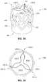
- FIG. 1Bis a top down view depicting an example embodiment of a prosthetic valve.
- FIGS. 1C-1Dare side views depicting an example embodiment of a prosthetic valve in expanded and contracted states, respectively.
- FIG. 1Eis a photograph depicting an example embodiment of a stent of a prosthetic valve.
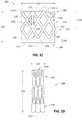
- FIGS. 2A-2Bare side views depicting an example embodiment of a prosthetic valve in expanded and contracted states, respectively.
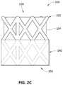
- FIG. 2Cis a side view depicting an example embodiment of a prosthetic valve.
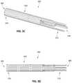
- FIG. 3Ais a perspective view of an example embodiment of a stent of a prosthetic valve in an expanded state.
- FIG. 3Bis a side view of the front half of an example embodiment of a stent of a prosthetic valve in an expanded state.
- FIGS. 3C-3Dare perspective and side views, respectively, of an example embodiment of a stent of a prosthetic valve in a contracted state.
- FIGS. 3E-3Fare partial cross-sectional views depicting the front half of an example embodiment of a valve within a cross-section of the aortic anatomy when the valve is in the open and closed states, respectively.
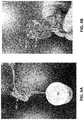
- FIGS. 4A-4Fare photographs of examples of various stages of valve manufacturing processes.
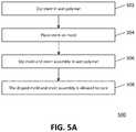
- FIG. 5Ais a flow diagram depicting an example embodiment of a method of manufacturing a valve.
- FIGS. 5B-5Care perspective views of an example embodiment of a mold before and after placement of an example stent thereon, respectively.
- FIG. 6Ais a flow diagram depicting an example embodiment of a method of manufacturing a valve.
- FIGS. 6B-6Care perspective and top down views, respectively, of an example embodiment of a stent of a valvular body in an expanded state.
- FIG. 6Dis a photograph depicting an example stage of manufacturing an example embodiment of a valve.
- FIGS. 7-10Aare flow diagrams depicting example embodiments of methods of manufacturing valves.
- FIG. 10Bis a cross-sectional view depicting an example embodiment of a valve during manufacturing.
- FIGS. 11-13Aare flow diagrams depicting example embodiments of methods of manufacturing valves.
- FIG. 13Bis a cross-sectional view depicting an example embodiment of a valve during manufacturing.
- the example embodiments described hereinrelate to improved implantable prosthetic valves, such as prosthetic heart valves having a support structure, stent, or frame coupled with two or more leaflets, and techniques for the manufacture and manufacturability of implantable valves. These embodiments are particularly suited for artificial polymeric leaflets, and the resulting artificial valves offer advantages comparable to current approaches with the added benefit of a longer life span. Valves with polymer-based leaflets are advantageous because polymers can offer the same structural support as biological tissue, while being much thinner and allowing the valve to be more easily contracted for delivery. This in turn results in less stress on the polymer as it is contracted which prevents long-term degradation of the valve leaflets. In addition, the manufacturing methods described herein permit fabrication of a valve without suturing leaflets to a support structure or stent, thus promoting high quality repeatable results.
- FIG. 1Ais a perspective view depicting an example embodiment of an implantable prosthetic valve 100 having a support structure or stent 102 and a valvular body 104 .
- the valvular bodyis configured as an aortic replacement valve and has three valve leaflets 110 - 1 , 110 - 2 , and 110 - 3 .
- Valve 100is configured to allow blood to flow from an upstream end 106 (sometimes referred to as the proximal end) to a downstream end 108 (sometimes referred to as the distal end) and valve 100 has a longitudinal axis 112 extending between upstream end 106 and downstream end 108 parallel to the primary direction of blood flow through the valve.
- valve 100 described hereincan be configured for transcatheter implantation, and thus can transition between, on the one hand, an expanded or operative configuration (having a relatively larger radial dimension) for regulating blood flow and, on the other hand, a contracted or deliverable configuration (having a relatively smaller radial dimension) that permits intravascular delivery.
- FIG. 1Bis an end view depicting downstream end 108 of valve 100 in the expanded configuration (with leaflets 110 in a partially open at-rest state) with the radial dimension or width of valve 100 indicated by reference 114 .
- FIGS. 1C and 1Dare side views depicting valve 100 in the expanded and contracted configurations, respectively.
- the longitudinal dimension or length of valve 100is indicated by reference 116 .
- Valve 100has a relatively larger radial dimension 114 and a relatively smaller longitudinal dimension 116 in the expanded configuration of FIG. 1C than in the contracted configuration of FIG. 1D , where valve 100 is longitudinally lengthened and radially shortened.
- FIG. 1Eis a photograph depicting an example embodiment of stent 102 in isolation.
- Stent 102is coupled with valvular body 104 and provides radial and longitudinal support for body 104 .
- the body of stent 102includes multiple struts 120 coupled together in a unitary or monolithic body. Each strut 120 is coupled with another strut at a location 122 that is deformable for transition of stent 102 between the expanded and contracted states.
- struts 120are interconnected in a crossing pattern, or lattice, such that multiple open regions 124 are present. These open regions 124 have a four-sided diamond shape in the configuration shown here.
- each strut 120is oriented at an angle with respect to longitudinal axis 112 , with the exception of strut 125 , which is an optional strut located parallel with longitudinal axis 112 .
- Strut 125provides additional support (e.g., resistance to tensile, compressive, and lateral force) at the position on stent 102 corresponding to the commissure position where leaflets 110 - 1 and 110 - 2 meet. These positions on stent 102 are indicated in FIG. 1B by reference numeral 111 .
- Two triangular-shaped open regions 126are present on each side of strut 125 .
- Each set of struts 120 and 125 forming an individual open region 124 or 126can be referred to as a cell of stent 102 , and the struts 120 and 125 can be part of two or more cells.
- Struts 125can provide resistance to deflection of the downstream portion of valve 100 when in the closed state, and can provide increased surface area for bonding or coupling the polymer of valvular body 104 to stent 102 .
- each rowincludes nine cells, although this is only an example and the rows can have other numbers of cells as stated below.
- Leaflets 110are located adjacent the downstream row 131 of cells, generally in region 134 .
- the upstream terminus 135 of valvular body 104can be at various locations with respect to the upstream terminus 136 of stent 102 .
- the upstream terminus 135 of valvular body 104is in a position farther upstream (or proximal) to upstream terminus 136 of stent 102 such that a length of valvular body 104 exists upstream to stent 102 .
- skirt 140This upstream portion of valvular body 104 can be referred to as a skirt 140 .
- Skirt 140can prevent or resist paravalvular leakage in some embodiments, and can also be placed over stent 102 to cover any sharp or abrasive edges that can otherwise introduce stress concentration to the valve as well as traumatize the surrounding tissue.
- skirt 140can be formed by electrospinning the polymer.
- valve 100can be configured such that the longitudinal axis of each of the plurality of struts 120 are parallel to longitudinal axis 112 of the valve or substantially parallel (e.g., about 5 degrees or less) to longitudinal axis 112 when valve 100 is in the fully contracted configuration.
- valvular body 104can fold or collapse upon itself radially, and also elastically deform longitudinally to permit longitudinal lengthening of stent 102 .
- valvular body 104can elastically return to its original shape.
- FIGS. 2A and 2Bare side views of another example embodiment of valve 100 in the expanded and contracted states, respectively.
- valve 100includes three rows of cells 201 - 203 .
- a first vertical strut 125 - 1is present in the first row 201 of cells to provide additional support at commissure position 111 - 1 where leaflets 110 - 1 and 110 - 2 meet.
- a second strut 125 - 2is present in the third row of cells 203 , directly upstream to first strut 125 - 2 , to provide additional support at location 111 - 1 .
- Both first and second struts 125 - 1 and 125 - 2are optional, and each is preferably elastic to permit longitudinal lengthening of stent 102 during contraction.
- Embodiments of valve 100can have zero, one, or more struts 125 at each of the locations 111 where leaflets 110 meet.
- Embodiments of valve 100can also have only one row of cells, or two or more rows of cells, and each row can include any number of two or more cells. In many embodiments each row includes a number of cells that is an integer multiple of the number of leaflets.
- FIG. 2Cdepicts a side view of another example embodiment of valve 100 similar to that of FIGS. 2A and 2B , except skirt 140 has been placed (e.g., rolled or inverted) over the upstream side of stent 102 .
- skirt 140can be placed over any desired length of stent 102 (e.g., 10%, 25%, 50%, 75%, 100%). If stent 102 is metallic and skirt 140 is placed over the entire length of stent 102 , then skirt 140 can also function to electrically insulate stent 102 .
- Skirt 140can be bonded (e.g., through curing of the polymer or otherwise) to the exterior of the upstream side or portion of stent 102 , or can rest on the exterior upstream side without being bonded thereto.
- Valve 100can be carried in the contracted configuration within a lumen of a tubular, elongate delivery device (e.g., a catheter) or restrained in the contracted configuration and carried on the outer diameter of the delivery device, which in turn can be tubular or non-tubular.
- Valve 100can be biased to autonomously expand from the contracted configuration to the expanded configuration upon release from the constraint imposed by the delivery device (sometimes referred to as a “self-expanding” valve).
- Both stent 102 and valvular body 104can be an elastic material that returns to the expanded configuration after contraction. Alternatively, stent 102 can be elastic and serve as the primary or sole bias to return valve 100 to the expanded configuration.
- Valve 100can also be configured to require the application of external force (such as from a balloon or other mechanism) to cause expansion to the expanded configuration.
- valve 100includes a contoured stent 302 coupled with valvular body 104 .
- FIGS. 3A-3Bare perspective and side views, respectively, of stent 302 in the expanded state (without valvular body 104 )
- FIGS. 3C-3Dare perspective and side views, respectively, of stent 302 in the contracted state (without valvular body 104 )
- FIGS. 3E-3Fare cross-sections of the aortic anatomy depicting side views of valve 100 within that anatomy while in the open and closed states, respectively.
- stent 302is a self-expanding frame of non-uniform radius having an upstream (proximal) end 306 and a downstream (distal) end 308 .
- Downstream end 308has a first (or primary) crown 310 as well as a second (or secondary) crown 320 that can extend radially outward farther than primary crown 310 .
- Primary crown 310extends farther distally than secondary crown 320 .
- a third (or tertiary) crown 330is located at upstream end 306 of stent 302 .
- a necked down region (or waist) 340is present between crown 330 , on the one hand, and crowns 310 and 320 , on the other hand. Waist 340 is where stent 302 has the relatively smallest radial width.
- Each of crowns 310 , 320 , and 330extends radially outwards (e.g., flares) from waist 340 .
- Primary crown 310is a continuation of the lattice arrangement of stent 302 and includes three crown segments 311 - 1 , 311 - 2 , and 311 - 3 in locations where adjacent leaflets (not shown) meet.
- Primary crown 310mimics the tri-leaflet geometry of a natural heart valve in order to provide optimal attachment of artificial leaflets 110 ( FIGS. 3E-3F ).
- Bioprosthetic (natural tissue) leafletscan alternatively be attached (e.g., sutured) onto stent 302 .
- the tri-leaflet geometryensures a high effective orifice area (EOA).
- Primary crown 310By mimicking the natural shape of a heart valve, the stresses associated with normal operating conditions of the valve material are more evenly spread across stent 302 , increasing the overall longevity of the device.
- Primary crown 310also mimics the compliance of natural heart valve attachment sites by deflecting, which further distributes stress associated with systolic cycle loading over valve 100 . This deflection also allows easier access for blood to flow through the aortic sinuses.
- Secondary crown 320is also a continuation of the regular lattice of stent 302 and includes three crown segments 321 - 1 , 321 - 2 , and 321 - 3 that flare outwardly to a greater extent that primary crown 310 (see FIG. 3B ).
- Each secondary crown segment 321assists in fixation of valve 100 within the anatomy.
- Segments 321also include alignment holes 351 (e.g., in the distal most strut) that can receive a thread, tether, or other portion of a delivery device and can be used to physically manipulate the position of valve 100 in three-dimensional space, as well as to radially rotate or tilt valve 100 during implantation. Such control assists the medical professional in achieving precise alignment.
- Alignment holes 351can also be used for device retrieval if the surgeon should need to re-align the device after deployment.
- Tertiary crown 330 located on the proximal end of the framehas a slight outward expansion that assists in fixation.
- Stent 302has the ability to self-locate within the anatomy when used as, e.g., an aortic or mitral valve. For example, when configured as an aortic replacement valve, waist 340 is receptive to placement immediately adjacent the aortic annulus.
- FIGS. 3E and 3Fdepict this embodiment of valve 100 configured as an aortic valve and deployed within the aortic anatomy with valve 100 in the open and closed states, respectively.
- Waist 340 of valve 100is adjacent annulus 351 (which bulges into the interior of the aorta) with primary crown 310 and secondary crown 320 located downstream of annulus 351 in the ascending aorta 353 , and tertiary crown 330 located upstream of annulus 351 .
- Valve 100is sized such that the radial dimension of the crowns 310 , 320 , and 330 , exceeds the radial dimension of annulus 351 and waist 340 when waist 340 is expanded in the anatomy.
- Valve 100may be slightly oversized to ensure adequate fixation, and may not expand to the maximum radial dimension when implanted.
- Valve 100has a compliant nature. During flow conditions ( FIG. 3E ) leaflets 110 are open and allowing flow, but when valve 100 closes ( FIG. 3F ) crown segments 311 of primary crown 310 deflect radially inwards allowing blood to flow easily into and though aortic sinuses 352 . Crown segments 321 of secondary crown 320 can also deflect inwards to a lesser degree without impacting the fixation of valve 100 .
- valve 100 described hereinare arrived at by accounting for design considerations such as minimization of the overall size of stent 102 and 302 , prevention of interference with the electrical conduction pathways of the heart, minimization of the fluidic pressure gradient across valve 100 , as well as the prevention of blockage of any of the three aortic sinuses.
- the overall aspect ratiolength and width
- the ratio of primary crown height to overall lengthcan be about 1:2.
- each crown segment of both the secondary and tertiary crownscan be 50° and can vary up to and including 60° to promote the stents ability to be crimped and placed inside a delivery device while at the same time providing enough radial force to sufficiently fix valve 100 in the ventricular outflow tract (VOT).
- VOTventricular outflow tract
- Many embodiments of valve 100can be contracted such that the circumference is reduced by 84% or more. Additional rows of cells may also be added for additional stability in the VOT as well as to increase the radial force stent 102 or 302 exerts on the surrounding tissue.
- valve 100 described with respect to FIGS. 3A-3Fdiffers from the embodiments of FIGS. 1A-2C primarily in the contoured profile and the presence of multiple downstream crowns, but all other features and variations of valve 100 described with respect to FIGS. 1A-2C can likewise be applied to the example embodiment of FIGS. 3A-3F .
- valve 100While the embodiments of valve 100 have a generally right cylindrical upstream end, these embodiments can alternatively have a curved or scalloped upstream end. Scalloped ends are known to those of skill in the art (see, e.g., U.S. Pat. No. 9,301,837, which is incorporated by reference herein in its entirety and for all purposes.
- secondary crown 320 and/or tertiary crown 330can be omitted if desired.
- either or both of crowns 320 and 330can be included but can have a constant radius along their length such that the sides of stent 302 where crowns 320 and/or 330 are present are parallel to the longitudinal axis of stent 302 .
- stents 102 and 302are preferably fabricated in stages from one or more materials (e.g., a primary or core structure of one material with a secondary structure or coating of the same or another material).
- the material for the primary structureis preferably elastic or superelastic. Examples of such materials include titanium alloys (e.g., nitinol), elgiloy, stainless steel, and various polymers.
- Materials for the secondary coatingcan include polymeric materials such as polyether ether ketones (PEEK), polyurethanes, a polyetherimides (PEI) such as ULTEM, any of the artificial materials used to form leaflets 110 , and others.
- Leaflets 110can be fabricated from polymeric materials, including any biostable polyurethanes and polyurethane compositions (e.g., polysiloxane-containing polyurethanes, etc.) known in the art. Examples of polyurethane-containing leaflets are described in U.S. Pat. Nos. 6,984,700, 7,262,260, 7,365,134, U.S. Patent Publ. No. 2017/0119923 (“Polyurethane/urea Compositions”), and Yilgor et al., “Silicone containing copolymers: Synthesis, properties and applications,” Prog. Polym. Sci. (2013), all of which are incorporated by reference herein in their entirety for all purposes. Materials that approach ideal isotropic non-creeping characteristics are particularly suitable for use in many embodiments. Leaflets 110 can also be fabricated from biological tissue (e.g., a porcine valve).
- biological tissuee.g., a porcine valve
- valves 100 having artificial polymeric leaflets 110Numerous embodiments of systems, devices, and methods of manufacturing valves 100 having artificial polymeric leaflets 110 are described herein. These systems, devices, and methods can be applied to any stent geometry or polymer, extending the valve's possible applications to involve the treatment of multiple conditions simultaneously, such as incorporating drug eluting technologies to reduce inflammation due to the foreign body response of the recipient's immune system. In addition, the manufacturing methods described here can be automated and/or robotized for inexpensive and repeatable manufacturing.
- the manufacturing methodsinvolve the fabrication of stent 102 or 302 and then either coupling leaflets 110 or valvular body 104 thereto, or integrally forming leaflets 110 thereon.
- these systems, devices, and methodsare described herein with respect to fabrication of a valve 100 having stent 102 , however it is stressed that all such systems, devices, and methods can likewise be used to fabricate embodiments of valve 100 having contoured stent 302 .
- the manufacturing embodiments described hereinutilize a dip casting or dipping process, however those of ordinary skill in the art will recognize that other comparable formation processes (e.g., molding) can be used instead.
- Dippingis used because the uniform effect of gravity onto the polymer as it cures ensures that the resulting mold is created at the lowest energy state of the polymer. This eliminates stress concentrations in the macro and micro-structure of the polymer that can result from other common molding techniques such as injection molding, thus greatly extending the valve's lifespan.
- valve 100in addition to the use of a contractable stent structure more readily allows valve 100 to be implanted in a non-invasive catheter based procedure because the stent will retain the ability to be contracted or crimped into a smaller diameter than its resting size.
- FIGS. 4A-4Fare photographs of various stages of valve manufacturing that will be referenced in conjunction with described the present embodiments.
- FIGS. 4A-4Fare examples of manufacturing primarily by hand (manually), but these stages can be automated for use in a higher volume manufacturing line.
- the manufacturing embodiments described hereincan utilize any of the approaches described in Int'l Patent Application PCT/US18/45202 filed Aug. 3, 2018 and titled “Systems, Devices, and Methods Relating to the Manufacture of Prosthetic Valves,” which is incorporated by reference herein in its entirety and for all purposes.
- FIG. 5Ais a flow diagram depicting an example embodiment of a method 500 of manufacturing valve 100 .
- stent 102is dipped in a wet polymer 402 contained within a vessel 404 ( FIG. 4A ).
- the actual movement of the structure into the wet polymercan be automated with a computer-controlled device.
- dippingrefers to the acts of placing the element to be dipped (e.g., stent, mold, valve) into the wet polymer and subsequently removing it. The dipping can be performed such that at least one end, but preferably all of stent 102 is coated or encapsulated in the polymer.
- Stent 102can be partially cured to allow excess polymer to run off, or stent 102 can proceed directly (without curing) to 504 .
- stent 102can be placed onto a mold 520 configured to form valvular body 104 and leaflets 110 .
- Mold 520can also be referred to as a former or mandrel and can be shaped cylindrically or in any other desired fashion to produce the components of valve 100 .
- Mold 520can have a contoured surface for formation of valve leaflets 110 , although such is not required.
- FIG. 5Bis a perspective view depicting mold 520
- FIG. 5Cis a perspective view depicting mold 520 after coupling with stent 102 , resulting in a mold and stent assembly 540 .
- upwarde.g., “facing upward”
- downstream end 522is facing upward.
- mold 520is turned upside down from the orientation depicted here, such that upstream end 521 of mold 520 is above downstream end 522 (upstream end 521 is facing upward and downstream end 522 is facing downward).
- Mold 520includes a base portion 523 with a geometry configured to form to upstream portion of valvular body 104 .
- Mold 520also includes a leaflet portion 524 with a surface that forms a negative image of the interior geometry of leaflets 110 in a partially open at-rest position.
- leaflet portion 524is a run-off portion 526 that allows excess polymer to run-off or drain away from leaflets 110 after dipping, if the curing process takes place with downstream end 522 of mold facing downward (in some embodiments, curing can take place while downstream end 522 faces upward).
- the polymer that cures on run-off portion 526can be removed during leaflet finishing where, e.g., leaflets 110 are trimmed to their final dimensions. In some embodiments, the trimming step can involve removal of run-off portion 526 itself from mold 520 .
- stent 102is placed on mold 520 such that the three draft angles 528 (located between each pair of adjacent leaflets on mold 520 ) are aligned with the proper respective positions on stent 102 , which can be positions corresponding to commissure positions where adjacent leaflets meet (e.g., positions 111 of FIG. 1B ). In this embodiment, these positions are downstream termini of three crown segments 530 . Placement can be such that struts 120 forming crown segments 530 coincide with the draft angle 528 , as shown in FIG. 5C .
- Alignment of struts 120 with draft angle 528allows even distribution of stress to stent 102 , and also allows the struts of each crown segment 530 aligned with draft angle 528 to deflect radially inward during operation of valve 100 .
- This deflectioncan absorb strain energy resulting from the closing of valve leaflets 110 that would otherwise result in strain on leaflet 110 itself.
- this deflectionincreases the likelihood of clearance of all aortic sinuses even if valve 100 is misaligned when implanted.
- mold and stent assembly 540can be dipped into wet polymer such that run-off portion 526 is submerged first.
- mold 520can be submerged until at least leaflet portion 524 of mold 520 is covered. The extent to which base portion 523 is submerged can vary.
- valvular body 104is configured with a skirt 140
- submergence of mold 520should continue at least far enough to form skirt 140 .
- Mold 520can be submerged past the desired upstream terminus of skirt 140 and any excess polymer can be trimmed to form skirt 140 .
- This dipping at 506preferably occurs with the same polymer as used at 502 , although a different batch may be used.
- the polymer used in 506may have a different viscosity or chemical composition from the polymer used at 502 .
- the dipping stepscan occur under both high temperature and humidity, for example with a relative humidity (RH) in the range of 20-80% and a temperature in the range of 20-50 degrees C.
- RHrelative humidity
- each dipping stepin this and all embodiments described herein
- assembly 540is allowed to cure such that downstream end 522 is facing downward and the polymer can drain along run-off portion 526 .
- the curing recipewill vary depending on the type of polymer used. After curing, stent 102 and valvular body 104 will be securely fixed together to form valve 100 .
- valve 100can be complete after curing, or valve 100 can be subjected to valve finishing to finalize the valve structure.
- finishingcan include trimming or modifying the surface of leaflets 110 to their final or near final state (e.g., through laser cutting, ultrasonic trimming, water knife, a mechanical clam shell cutter, and the like), applying additional coatings or surface treatments to valve 100 , moving skirt 140 (e.g., rolling skirt 140 over stent 102 ), attaching additional structures to valve 100 (such as bands or tensioning elements as described herein), or others. Packaging and sterilization of the finished valve can then occur.
- trimming of leaflets 110can occur once leaflets 110 are cured. In this and all other embodiments described herein, trimming of leaflets 110 can occur once leaflets 110 are cured, regardless of whether additional manufacturing steps (e.g., mating of valvular body 104 with stent 102 ) are still to be performed.
- FIG. 6Ais a flow diagram depicting another example embodiment of a method 600 of manufacturing valve 100 .
- stent 102is dipped in wet polymer such that at least a portion, preferably all, of the stent body is encapsulated in polymer ( FIG. 4A ).
- stent 102is allowed to completely cure to a dry state or substantially cure to a substantially dry state.
- Coating of stent 102can be performed as part of method 600 or stent 102 can be precoated, or the coating can be omitted.
- valvular body 104is formed. This can occur at 606 - 610 .
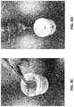
- FIGS. 6B and 6Care perspective and top down views of an example embodiment of valvular body 104 (having upstream end 630 and downstream end 632 ) after removal from mold 520 .
- FIG. 6Dis a photograph of an example embodiment of valvular body 104 partially positioned over a stent, in this instance stent 302 .
- the valvular body and stent assemblyis then dipped in polymer such that the upstream end is submerged first, preferably over an upstream portion 634 of valvular body 104 ( FIG. 6B ), but preferably stopping short of leaflets 110 , to attach valvular body 104 to stent 102 .
- valve 100is then allowed to cure while upstream end 106 is facing downward. Then valve 100 can be finished as needed, including any necessary trimming to upstream end 106 and rolling or inverting skirt 140 over stent 120 ( FIG. 2C ) if desired.
- FIG. 7is a flow diagram depicting another example embodiment of a method 700 of manufacturing valve 100 .
- Valvular bodycan be formed, e.g., at 702 - 704 .
- mold 520is dipped into wet polymer such that downstream end 522 is submerged first and continued until leaflet portion 524 and optionally at least a portion of base portion 523 is submerged, after which mold 520 is removed ( FIG. 4D ).
- mold 520is then hung with downstream end 522 beneath upstream end 520 (such that excess polymer runs off run-off portion 526 ) and the polymer is allowed to completely cure to a dry state or substantially completely cure to a substantially dry state to form valvular body 104 ( FIG. 4E ).
- stent 102is dipped in order to at least partially, and preferably entirely, encapsulate stent 102 in polymer.
- stent 102while in a wet state, is positioned over valvular body 104 and mold 520 and properly aligned as needed (see FIG. 4B ).
- assembly 540is then dipped again such that upstream end 521 is submerged first (see FIG. 4C ).
- Assembly 540is dipped to cover an upstream portion of valvular body 104 (like portion 634 of FIG. 6B ), but preferably stopping short of leaflets 110 .
- the dipping at 710can form skirt 140 .
- valve 100can then be finished as needed, including any necessary trimming to upstream end 106 and rolling or inverting skirt 140 over stent 120 ( FIG. 2C ) if desired.
- FIG. 8is a flow diagram depicting another example embodiment of a method 800 of manufacturing valve 100 .
- mold 520is dipped into wet polymer such that downstream end 522 is submerged first, leaflet portion 524 is covered, and optionally at least a portion of base portion 523 is covered.
- stent 102is dipped in order to at least partially, and preferably entirely, encapsulate stent 102 in polymer. 802 and 804 can be performed in any order or concurrently.
- stent 102is positioned over body 104 on mold 520 and aligned as needed.
- the assemblyis allowed to cure with downstream end 108 facing up. Curing the assembly while in this orientation utilizes gravity to create skirt 140 out of excess polymer running over base portion 523 of mold 520 . This excess polymer would otherwise drip off run-off portion 526 of mold 520 .
- Valve 100can then be removed from mold 520 and finished as needed, including any necessary trimming to upstream end 106 and rolling or inverting skirt 140 over stent 120 ( FIG. 2C ) if desired.
- FIG. 9is a flow diagram depicting another example embodiment of a method 900 of manufacturing valve 100 .
- mold 520is dipped into wet polymer such that downstream end 522 is submerged first, leaflet portion 524 is covered, and optionally at least a portion of base portion 523 is covered.
- mold 520is then hung with downstream end 522 beneath upstream end 521 (such that excess polymer runs off run-off portion 526 ) and the polymer is allowed to completely cure to a dry state or substantially completely cure to a substantially dry state to form valvular body 104 ( FIG. 4E ).
- stent 102is fixed around a mandrel (e.g., a cylindrical mandrel).
- stent 102 and the mandrelare dipped in order to at least partially, and preferably entirely, encapsulate stent 102 in polymer (see FIG. 4F ).
- Use of the mandrelassists in forming a uniform and repeatable inner diameter to the stent body as well as establishing skirt 140 .
- stent 102is allowed to cure.
- stent 102is placed over valvular body 104 (e.g., while still on mold 520 ) and stent 102 is bonded to body 104 .
- skirt 140can be rolled or inverted over stent 120 ( FIG.
- Valve 100can then be finished as needed.
- FIG. 10Ais a flow diagram depicting another example embodiment of a method 1000 for manufacturing valve 100 .
- mold 520is dipped into wet polymer such that downstream end 522 is submerged first, leaflet portion 524 is covered, and optionally at least a portion of base portion 523 is covered.
- mold 520is then hung with downstream end 522 beneath upstream end 520 (such that excess polymer runs off run-off portion 526 ) and the polymer is allowed to completely cure to a dry state or substantially completely cure to a substantially dry state to form valvular body 104 ( FIG. 4E ).
- leaflets 110can optionally be trimmed and/or otherwise finished while valvular body 104 is on mold 520 .
- stent 102is dipped in order to at least partially, and preferably entirely, encapsulate stent 102 in polymer.
- valvular body 104is placed inside stent 102 , preferably while valvular body 104 is still on mold 520 , and aligned with stent 102 .
- skirt 140can be rolled, inverted, or otherwise placed over the upstream side of stent 102 (see FIG. 2C ).
- FIG. 10Bis a cross-sectional view of mold 520 having valvular body 104 thereon (after trimming of leaflets 110 and removal of run-off portion 526 ).
- Stent 102is over valvular body 104 and skirt 140 has been rolled over stent 102 .
- the assemblyis within an interior space 1005 of outer mandrel 1001 .
- An optional tubular debonding shim 1003can be placed between the exterior of stent 102 and the interior of skirt 140 to prevent adhesion of the two.
- valve 100exerts force on valve 100 to assist in curing stent 102 to valvular body 104 and forming sufficient securement of the two elements together.
- valve 100can be removed from outer mandrel 1001 and mold 520 .
- any debonding shim 1003can be removed from valve 100 and, also, an optional band or other tensioning element (e.g., pre-stretched) can be placed around skirt 140 to hold skirt 140 in place around stent 102 if desired.
- the tensioning elementcan be hydrophilic such that it swells within the body, which can assist in the prevention of paravalvular leakage. Valve 100 can then be finished as needed.
- FIG. 11is a flow diagram depicting another example embodiment of a method 1100 for manufacturing valve 100 .
- mold 520is dipped into wet polymer such that downstream end 522 is submerged first, leaflet portion 524 is covered, and optionally at least a portion of base portion 523 is covered.
- mold 520is then hung with downstream end 522 beneath upstream end 520 (such that excess polymer runs off run-off portion 526 ) and the polymer is allowed to completely cure to a dry state or substantially completely cure to a substantially dry state to form valvular body 104 ( FIG. 4E ).
- leaflets 110can optionally be trimmed and/or otherwise finished while valvular body 104 is on mold 520 .
- stent 102is optionally dipped in polymer in order to at least partially, and preferably entirely, encapsulate stent 102 in polymer.
- stent 102(if dipped) can be allowed to cure to a dry state.
- valvular body 104can be placed inside and aligned with stent 102 , preferably after valvular body 104 has been removed from mold 520 .
- 1112is performed while stent 102 is dry, but in other embodiments stent 102 can be in a wet state after dipping in wet polymer.
- stent 102is partially contracted or crimped towards its contracted configuration using outer mandrel 1001 or another crimping device.
- skirt 140can be rolled, inverted, or otherwise placed over the upstream side of stent 102 .
- Skirt 104is preferably of a radial dimension that is less than the fully self-expanded radial dimension of stent 102 , and thus stent 102 and valvular body 104 are held together by the expansive force applied by stent 102 against the interior of skirt 140 .
- stent 102can be allowed to radially expand back to its expanded state, or until the resistance applied by skirt 140 impedes further expansion. This can be accomplished by removing stent 102 from outer mandrel 1001 .
- An optional band or other tensioning elemente.g., pre-stretched
- the tensioning elementcan be hydrophilic such that it swells within the body, which can assist in the prevention of paravalvular leakage. Valve 100 can then be finished as needed.
- FIG. 12is a flow diagram depicting another example embodiment of a method 1200 for manufacturing valve 100 .
- mold 520is dipped into wet polymer such that downstream end 522 is submerged first, leaflet portion 524 is covered, and optionally at least a portion of base portion 523 is covered.
- mold 520is then hung with downstream end 522 beneath upstream end 520 (such that excess polymer runs off run-off portion 526 ) and the polymer is allowed to completely cure to a dry state or substantially completely cure to a substantially dry state to form valvular body 104 ( FIG. 4E ).
- leaflets 110can optionally be trimmed and/or otherwise finished while valvular body 104 is on mold 520 .
- stent 102is optionally dipped in order to at least partially, and preferably entirely, encapsulate stent 102 in polymer. At 1210 , if dipped, then stent 102 can be allowed to cure.
- Valvular body 104can then be removed from mold 520 and, at 1212 , at least a portion of skirt 140 on an upstream side of valvular body 104 can be placed over a portion of the exterior of stent 102 . In doing so, leaflets 110 of valvular body 104 are aligned with stent 102 , e.g., with struts or crown segments on stent 102 configured for alignment with commissure locations between leaflets 110 . At 1214 , the downstream end or side of valvular body 104 is inverted or rolled into the interior (inner lumen) of stent 102 such that leaflets 110 are positioned in the within stent 102 in a manner that permits leaflets to operate to regulate the flow of blood.
- An optional band or other tensioning element(e.g., pre-stretched) can then be placed around skirt 140 to add further securement.
- the tensioning elementcan be hydrophilic such that it swells within the body, which can assist in the prevention of paravalvular leakage. Valve 100 can then be finished as needed.
- FIG. 13Ais a flow diagram depicting another example embodiment of a method 1300 for manufacturing valve 100 .
- upstream end 521 of mold 520is inserted into stent 102 (which can be previously dipped and cured if desired) such that at least a portion of stent 102 is over on base portion 523 of mold 520 , but not extending over leaflet portion 524 of mold 520 (e.g., not as far as depicted in FIG. 5C ).
- Upstream end 521 of mold 520can include a taper to assist in insertion if desired.
- a round band or other tensioning elementcan optionally be placed over the exterior of stent 102 to hold it to mold 520 .
- FIG. 13Bis a cross-sectional view depicting an example of such an arrangement with band 1305 placed over stent 102 .
- upstream end 521 of mold 520includes a tapered portion 529 .
- mold 520is dipped into wet polymer such that downstream end 522 is submerged first, leaflet portion 524 is covered, and a portion of base portion 523 is covered, preferably up to or near to the upstream terminus of band 1305 .
- mold 520is then hung with downstream end 522 beneath upstream end 520 (such that excess polymer runs off run-off portion 526 ) and the polymer is allowed to completely cure to a dry state or substantially completely cure to a substantially dry state to form valvular body 104 .
- leaflets 110can optionally be trimmed and/or otherwise finished while valvular body 104 is on mold 520 .
- valve 100can then be finished as needed.
- Mold 520in all of the embodiments described herein, can be configured such that leaflet forming portion 524 does not include an image of leaflets 110 but rather has a cylindrical or substantially cylindrical shape, as is known to those of ordinary skill in the art. Such a shape will result in a cylindrical or substantially cylindrical portion of valvular body 104 where leaflets 110 are to be positioned, and those leaflets 110 can then be formed by trimming and/or shaping valvular body 104 accordingly.
- commissure of valvular body 104 between adjacent leaflets 110can be bonded, sewn, or otherwise secured to stent 102 thru additional methods to provide additional support at that location.
- one or more anchors, barbs, abutments, or other structures that extend radially outwards from valve 100can be positioned on stent 102 and/or valvular body 104 , such as near upstream end 106 .
- Such elementscan act as fasteners that assist in lodging valve 100 to the surrounding tissue after implantation.
- mold 520 and/or mandrel 1001can be a material (or be coated with a material) that resists cohesion with the polymer(s) used. Such a configuration can make it easier to remove valvular body 104 and/or stent 102 from mold 520 and/or mandrel 1001 .
- polymers having different characteristicscan be used. These characteristics can include viscosity, chemical composition, the presence of additives, and the like.
- mold 520 and stent 102can each be dipped in a polymer having the same characteristics, or different characteristics. If mold 520 and/or stent 102 is dipped multiple times in an embodiment, then each dipping can be with a polymer having the same or a different characteristic.
- valve 100described herein are trileaflet (three leaflet) valves, although valve 100 can be implemented and manufactured as a bileaflet (two leaflet) valve in the alternative.
- valve 100can be implemented and manufactured as a bileaflet (two leaflet) valve in the alternative.
- bileaflettwo leaflet valve
- an implantable valvein many example embodiments, includes: a stent including a plurality of deflectable struts; and a polymeric valvular body coupled with the stent, the polymeric valve body including a plurality of artificial leaflets, where the implantable valve has a radial dimension and is transitionable between a contracted state and an expanded state, where the radial dimension is relatively smaller in the contracted state than in the expanded state.
- the stent and valvular bodycan be coupled together with cured polymer.
- the stentcan be encapsulated in the cured polymer.
- the polymeric valvular bodycan be composed of the cured polymer.
- the implantable valvecan have a longitudinal axis and, when the implantable valve is in the expanded state, the plurality of deflectable struts are transverse to the longitudinal axis. When in a fully contracted state, the plurality of deflectable struts can be parallel or substantially parallel to the longitudinal axis.
- the valvecan further include a plurality of longitudinal struts, each of the plurality of longitudinal struts positioned at a commissure between adjacent leaflets. Each of the plurality of longitudinal struts can be parallel to a longitudinal axis of the implantable valve when the implantable valve is in the expanded and contracted configurations.
- the plurality of deflectable strutscan cross and form a plurality of cells.
- the stentcan include a first row of cells located adjacent a downstream end of the stent, where the plurality of longitudinal struts are in the first row of cells.
- the stentcan include a second row of cells located upstream of the first row of cells, where no longitudinal strut is in the second row of cells.
- the valvular bodycan include a skirt located upstream from an upstream end of the stent.
- the skirtcan extend over the upstream end of the stent.
- the skirtcan extend over an exterior upstream portion of the stent.
- the skirtcan extend over the exterior upstream portion of the stent and can be unconnected (not bonded) to the exterior upstream portion of the stent.
- the stentcan include a primary crown and a secondary crown.
- the primary crowncan include a plurality of primary crown segments and the secondary crown can include a plurality of secondary crown segments.
- a downstream terminus of each of the plurality of primary crown segmentscan be radially aligned with an interface between adjacent leaflets.
- Each of the plurality of secondary crown segmentscan have a downstream terminus that is upstream of the downstream terminus of each of the plurality of primary crown segments.
- the stentcan include a waist, and where the primary and secondary crowns extend radially outwards relatively farther than the waist when the implantable valve is in the expanded configuration.
- the secondary crowncan extend radially outwards relatively farther than the primary crown when the implantable valve is in the expanded configuration.
- the secondary crowncan be configured to deflect from a first position radially outwards when the valve opens and deflect back to the first position when the valve closes.
- the stentcan include a tertiary crown located upstream of the primary and secondary crowns.
- the tertiary crowncan include a plurality of tertiary crown segments.
- An upstream terminus of the stentcan be formed by an upstream terminus of each of the plurality of tertiary crown segments.
- the stentcan include a waist, and the primary crown, secondary crown, and tertiary crown can extend radially outwards relatively farther than the waist when the implantable valve is in the expanded configuration.
- the secondary crowncan extend radially outwards relatively farther than the primary crown and the tertiary crown when the implantable valve is in the expanded configuration.
- the plurality of leafletscan be two and only two leaflets, or the plurality of leaflets can be three and only three leaflets. Other numbers of leaflets can also be used.
- the implantable valvecan be configured to replace an aortic valve of a human heart.
- the implantable valvecan be configured to replace a mitral valve of a human heart.
- the stentcan include a primary structure with a secondary structure coated over the primary structure.
- methods of implanting a prosthetic valveinclude: moving the prosthetic valve, with an elongate delivery device while the prosthetic valve is in a contracted state, through a body of a recipient; and implanting the prosthetic valve in the body of the recipient by, at least, deploying the prosthetic valve from the delivery device, where the prosthetic valve is implanted in an expanded configuration, and where the prosthetic valve is in accordance with any of the aforementioned valve embodiments.
- first methods of manufacturing an implantable valveinclude: dipping a stent in wet polymer; placing the stent on a mold; dipping the mold and stent into wet polymer such that at least a portion of the mold and at least a portion of the stent are covered in a polymer coating; and allowing the polymer coating to cure.
- the moldcan include a contoured surface to form leaflets.
- the stentcan be placed on the mold such that the stent is aligned with the contoured surface on the mold.
- the contoured surface of the moldhas a draft angle that is aligned with a commissure position on the stent.
- These example embodiments of first methodscan include trimming the polymer coating to form a plurality of leaflets. They can include removing the stent and polymer coating from the mold.
- dipping the stent in wet polymercan form a wet polymer coating on the stent
- placing the stent on the moldcan include placing the stent with the wet polymer coating on the mold.
- first methodscan include finishing the polymer coating to form the implantable valve.
- the implantable valvecan be in accordance with any of the aforementioned valve embodiments.
- second methods of manufacturing an implantable valveinclude: forming a polymeric valvular body; positioning the polymeric valvular body over a stent; dipping an upstream portion of the stent and polymeric valvular body in wet polymer such that a polymer coating is placed on the upstream portion; and allowing the polymer coating to cure.
- forming the polymeric valvular bodycan include: dipping a mold in wet polymer to form a polymer coating on the mold; allowing the polymer coating on the mold to cure; and trimming the valvular body to form a plurality of leaflets.
- the moldcan include a contoured surface to form the plurality of leaflets.
- These example embodiments of second methodscan also include: dipping the stent in wet polymer; and allowing the dipped stent to cure, prior to positioning the polymeric valvular body over the stent.
- the polymeric valvular bodycan be positioned over the stent such that the stent is aligned with the plurality of leaflets.
- the polymeric valvular bodycan be positioned over the stent such that commissure positions between adjacent leaflets are aligned with corresponding positions on the stent.
- the valvular bodycan include a plurality of leaflets, and the upstream portion of the stent and polymeric valvular body can be dipped in wet polymer such that the polymer coating is placed on the upstream portion and not on the plurality of leaflets.
- allowing the polymer coating to curecan include allowing the polymer coating to cure while an upstream end of the valvular body is facing downward.
- the implantable valvecan be formed after allowing the polymer coating to cure or after performing valve finishing to the stent or valvular body.
- the implantable valvecan be in accordance with any of the aforementioned valve embodiments.
- third methods of manufacturing an implantable valveinclude: forming a polymeric valvular body; dipping a stent in wet polymer; positioning the stent having wet polymer thereon over the polymeric valvular body; dipping an upstream portion of the stent and polymeric valvular body in wet polymer such that a polymer coating is placed on the upstream portion; and allowing the polymer coating to cure.
- forming the polymeric valvular bodycan include: dipping a mold in wet polymer to form a polymer coating on the mold; and allowing the polymer coating on the mold to cure.
- the moldcan include a contoured surface to form the plurality of leaflets.
- the stentcan be positioned over the valvular body such that the stent is aligned with a plurality of leaflets of the valvular body.
- the stentcan be positioned over the polymeric valvular body such that commissure positions between adjacent leaflets of the polymeric valvular body are aligned with corresponding positions on the stent.
- the valvular bodycan include a plurality of leaflets, and the upstream portion of the stent and polymeric valvular body are dipped in wet polymer such that the polymer coating is placed on the upstream portion and not on the plurality of leaflets.
- allowing the polymer coating to curecan include allowing the polymer coating to cure while an upstream end of the valvular body is facing downward.
- the implantable valvecan be formed after allowing the polymer coating to cure or after performing valve finishing to the stent or valvular body.
- the implantable valvecan be in accordance with any of the aforementioned valve embodiments.
- fourth methods of manufacturing an implantable valveinclude: dipping a mold in wet polymer to form a polymer coating in a wet state; dipping a stent in wet polymer; positioning the stent having wet polymer thereon over the polymer coating in the wet state; and allowing the stent and polymer coating to cure.
- the moldcan include a contoured surface to form a plurality of leaflets.
- the stentcan be positioned over the polymer coating in the wet state such that the stent is aligned with the contoured surface of the mold.
- allowing the polymer coating to curecan include allowing the polymer coating to cure while a downstream end of the mold is facing upward.
- the implantable valvecan be formed after allowing the polymer coating to cure or after performing valve finishing to the stent or valvular body.
- the implantable valvecan be in accordance with any of the aforementioned valve embodiments.
- fifth methods of manufacturing an implantable valveinclude: positioning a stent over a polymeric valvular body; and bonding the stent to the polymeric valvular body.
- These example embodiments of fifth methodscan further include forming the polymeric valvular body prior to positioning the stent over the polymeric valvular body.
- Forming the polymeric valvular bodycan include: dipping a mold in wet polymer; and allowing the wet polymer on the mold to cure.
- the moldcan include a contoured surface to form the plurality of leaflets.
- These example embodiments of fifth methodscan further include: dipping the stent in wet polymer; and allowing the wet polymer to cure prior to positioning the stent over the polymeric valvular body.
- the stentcan be positioned over the valvular body such that the stent is aligned with a plurality of leaflets of the valvular body.
- the stentcan be positioned over the polymeric valvular body such that commissure positions between adjacent leaflets of the polymeric valvular body are aligned with corresponding positions on the stent.
- bonding the stent to the polymeric valvular bodycan be performed with one of the following: polymeric bonding, solvent bonding, plasma bonding, or ultrasonic welding.
- the implantable valvecan be formed after allowing the polymer coating to cure or after performing valve finishing to the stent or valvular body.
- the implantable valvecan be in accordance with any of the aforementioned valve embodiments.
- sixth methods of manufacturing an implantable valveinclude: dipping a stent in wet polymer; positioning a polymeric valvular body within the stent having wet polymer thereon; positioning a skirt of the polymeric valvular body over the stent having wet polymer thereon; and allowing the wet polymer to cure.
- These example embodiments of sixth methodscan further include forming the polymeric valvular body prior to dipping the stent in wet polymer. Forming the polymeric valvular body can include: dipping a mold in wet polymer; and allowing the wet polymer on the mold to cure. These example embodiments of sixth methods, can further include trimming a plurality of leaflets on the valvular body.
- the polymeric valvular bodycan be positioned within the stent having wet polymer thereon while the polymeric valvular body is on the mold.
- the valvular bodyis positioned within the stent such that the stent is aligned with a plurality of leaflets of the valvular body.
- the polymeric valvular bodycan be positioned within the stent such that commissure positions between adjacent leaflets of the polymeric valvular body are aligned with corresponding positions on the stent.
- These example embodiments of sixth methodscan further include placing a debonding shim between the skirt and the stent.
- allowing the wet polymer to curecan include: placing the polymeric valvular body and stent within an outer mandrel.
- These example embodiments of sixth methodscan further include placing a tensioning element over the skirt after the skirt is positioned over the stent.
- the tensioning elementcan be placed over the skirt after the skirt is positioned over the stent and prior to allowing the wet polymer to cure.
- the implantable valvecan be formed after allowing the wet polymer to cure or after performing valve finishing to the stent or valvular body.
- the implantable valvecan be in accordance with any of the aforementioned valve embodiments.
- seventh methods of manufacturing an implantable valveinclude: positioning a polymeric valvular body within a stent; at least partially radially contracting the stent; positioning a skirt of the polymeric valvular body over the stent while at least partially radially contracted; and allowing the stent to expand.
- These example embodiments of seventh methodscan further include forming the polymeric valvular body prior to positioning the polymeric valvular body within the stent. Forming the polymeric valvular body can include: dipping a mold in wet polymer; and allowing the wet polymer on the mold to cure. These example embodiments of seventh methods can further include trimming a plurality of leaflets on the valvular body.
- the polymeric valvular bodycan be positioned within the stent while the polymeric valvular body is on the mold.
- the valvular bodycan be positioned within the stent such that the stent is aligned with a plurality of leaflets of the valvular body.
- the polymeric valvular bodycan be positioned within the stent such that commissure positions between adjacent leaflets of the polymeric valvular body are aligned with corresponding positions on the stent.
- These example embodiments of seventh methodscan further include coating the stent in polymer before positioning the polymeric valvular body within the stent.
- These example embodiments of seventh methodscan further include: dipping the stent in wet polymer; and allowing the wet polymer to cure before positioning the polymeric valvular body within the stent.
- These example embodiments of seventh methodscan further include placing a debonding shim between the skirt and the stent.
- At least partially radially contracting the stentcan include placing the polymeric valvular body and stent within an outer mandrel. Allowing the stent to expand can include removing the stent from the outer mandrel.
- These example embodiments of seventh methodscan further include placing a tensioning element over the skirt after the skirt is positioned over the stent.
- the implantable valvecan be formed after allowing the stent to expand or after performing valve finishing to the stent or valvular body.
- the implantable valvecan be in accordance with any of the aforementioned valve embodiments.
- eighth methods of manufacturing an implantable valveinclude: positioning a polymeric valvular body over at least a portion of a stent such that a portion of the polymeric valvular body having a plurality of leaflets extends past the stent; and inverting the portion of the polymeric valvular body such that the plurality of leaflets are positioned within the stent.
- These example embodiments of eighth methodscan further include forming the polymeric valvular body prior to positioning the polymeric valvular body over the stent. Forming the polymeric valvular body can include: dipping a mold in wet polymer; and allowing the wet polymer on the mold to cure. These example embodiments of eighth methods can further include trimming a plurality of leaflets on the valvular body.
- These example embodiments of eighth methodscan further include coating the stent in polymer before positioning the polymeric valvular body over at least the portion of the stent.
- These example embodiments of eighth methodscan further include: dipping the stent in wet polymer; and allowing the wet polymer to cure before positioning the polymeric valvular body over the at least the portion of the stent.
- the polymeric valvular bodycan be positioned over the at least the portion of the stent such that the plurality of leaflets are aligned with the stent.
- the polymeric valvular bodycan be positioned over the at least the portion of the stent such that commissure positions between adjacent ones of the plurality of leaflets are aligned with corresponding positions on the stent.
- These example embodiments of eighth methodscan further include placing a tensioning element over the polymeric valvular body.
- the implantable valveis formed after inverting the portion of the polymeric valvular body or after performing valve finishing to the stent or valvular body.
- the implantable valvecan be in accordance with any of the aforementioned valve embodiments.
- ninth methods of manufacturing an implantable valveinclude: inserting an upstream end of a mold into a stent; dipping the mold and stent into wet polymer to form a polymer coating; allowing the polymer coating to cure to form a valvular body; removing the valvular body and stent from the mold; and inverting a downstream side of the valvular body into the stent.
- These example embodiments of ninth methodscan further include applying a restraining band over an exterior of the stent and mold prior to dipping the mold and stent into wet polymer.
- allowing the polymer coating to cure to form a valvular bodycan include allowing the polymer coating to cure while a downstream end of the mold is facing downward.
- These example embodiments of ninth methodscan further include trimming a plurality of leaflets on the downstream side of the valvular body prior to removing the valvular body and stent from the mold.
- These example embodiments of ninth methodscan further include coating the stent in polymer before inserting the upstream end of the mold into the stent.
- These example embodiments of ninth methodscan further include: dipping the stent in wet polymer; and allowing the wet polymer to cure before inserting the upstream end of the mold into the stent.
- inserting the upstream end of the mold into the stentcan include aligning draft angle positions on the mold with corresponding positions on the stent.
- the implantable valvecan be formed after inverting the downstream side of the valvular body into the stent or after performing valve finishing to the stent or valvular body.
- the implantable valvecan be in accordance with any of the aforementioned valve embodiments.
Landscapes
- Health & Medical Sciences (AREA)
- Cardiology (AREA)
- Engineering & Computer Science (AREA)
- Biomedical Technology (AREA)
- Life Sciences & Earth Sciences (AREA)
- Transplantation (AREA)
- Heart & Thoracic Surgery (AREA)
- Vascular Medicine (AREA)
- Oral & Maxillofacial Surgery (AREA)
- Animal Behavior & Ethology (AREA)
- General Health & Medical Sciences (AREA)
- Public Health (AREA)
- Veterinary Medicine (AREA)
- Manufacturing & Machinery (AREA)
- Mechanical Engineering (AREA)
- Prostheses (AREA)
Abstract
Description
Claims (18)
Priority Applications (2)
| Application Number | Priority Date | Filing Date | Title |
|---|---|---|---|
| US16/215,376US11000369B2 (en) | 2017-12-11 | 2018-12-10 | Systems, devices, and methods relating to the manufacture of intravascularly implantable prosthetic valves |
| US17/231,892US20210228348A1 (en) | 2017-12-11 | 2021-04-15 | Systems, devices, and methods relating to the manufacture of intravascularly implantable prosthetic valves |
Applications Claiming Priority (4)
| Application Number | Priority Date | Filing Date | Title |
|---|---|---|---|
| US201762597099P | 2017-12-11 | 2017-12-11 | |
| US201862698749P | 2018-07-16 | 2018-07-16 | |
| US201862699467P | 2018-07-17 | 2018-07-17 | |
| US16/215,376US11000369B2 (en) | 2017-12-11 | 2018-12-10 | Systems, devices, and methods relating to the manufacture of intravascularly implantable prosthetic valves |
Related Child Applications (1)
| Application Number | Title | Priority Date | Filing Date |
|---|---|---|---|
| US17/231,892ContinuationUS20210228348A1 (en) | 2017-12-11 | 2021-04-15 | Systems, devices, and methods relating to the manufacture of intravascularly implantable prosthetic valves |
Publications (2)
| Publication Number | Publication Date |
|---|---|
| US20190343625A1 US20190343625A1 (en) | 2019-11-14 |
| US11000369B2true US11000369B2 (en) | 2021-05-11 |
Family
ID=66820949
Family Applications (2)
| Application Number | Title | Priority Date | Filing Date |
|---|---|---|---|
| US16/215,376ActiveUS11000369B2 (en) | 2017-12-11 | 2018-12-10 | Systems, devices, and methods relating to the manufacture of intravascularly implantable prosthetic valves |
| US17/231,892PendingUS20210228348A1 (en) | 2017-12-11 | 2021-04-15 | Systems, devices, and methods relating to the manufacture of intravascularly implantable prosthetic valves |
Family Applications After (1)
| Application Number | Title | Priority Date | Filing Date |
|---|---|---|---|
| US17/231,892PendingUS20210228348A1 (en) | 2017-12-11 | 2021-04-15 | Systems, devices, and methods relating to the manufacture of intravascularly implantable prosthetic valves |
Country Status (7)
| Country | Link |
|---|---|
| US (2) | US11000369B2 (en) |
| EP (1) | EP3723662A4 (en) |
| JP (3) | JP7480944B2 (en) |
| CN (1) | CN111801070B (en) |
| AU (3) | AU2018383609B2 (en) |
| CA (1) | CA3083533A1 (en) |
| WO (1) | WO2019118371A1 (en) |
Cited By (1)
| Publication number | Priority date | Publication date | Assignee | Title |
|---|---|---|---|---|
| US20200113681A1 (en)* | 2014-10-13 | 2020-04-16 | W. L. Gore & Associates, Inc. | Prosthetic valved conduit |
Families Citing this family (15)
| Publication number | Priority date | Publication date | Assignee | Title |
|---|---|---|---|---|
| US11833034B2 (en) | 2016-01-13 | 2023-12-05 | Shifamed Holdings, Llc | Prosthetic cardiac valve devices, systems, and methods |
| AU2018383609B2 (en)* | 2017-12-11 | 2024-11-21 | California Institute Of Technology | Systems, devices, and methods relating to the manufacture of intravascularly implantable prosthetic valves |
| DE102018208555A1 (en)* | 2018-05-30 | 2019-12-05 | Kardion Gmbh | Apparatus for anchoring a cardiac assist system in a blood vessel, method of operation, and method of making a device and cardiac assist system |
| AU2019325548B2 (en) | 2018-08-21 | 2025-06-26 | Shifamed Holdings, Llc | Prosthetic cardiac valve devices, systems, and methods |
| CN113260337A (en) | 2018-10-05 | 2021-08-13 | 施菲姆德控股有限责任公司 | Prosthetic heart valve devices, systems, and methods |
| CN113056302B (en) | 2018-10-19 | 2023-03-28 | 施菲姆德控股有限责任公司 | Adjustable medical device |
| WO2020190855A1 (en) | 2019-03-18 | 2020-09-24 | Foldax, Inc. | Systems, devices, and methods relating to the manufacture of implantable prosthetic valves |
| EP3941391B1 (en) | 2019-03-19 | 2024-12-04 | Shifamed Holdings, LLC | Prosthetic cardiac valve devices, systems |
| CN110074899A (en)* | 2019-04-08 | 2019-08-02 | 北京佰仁医疗科技股份有限公司 | It is a kind of for intervening the bracket of valve mesopetalum |
| CN116456937A (en) | 2020-08-31 | 2023-07-18 | 施菲姆德控股有限责任公司 | Prosthetic Valve Delivery System |
| US11197755B1 (en)* | 2020-10-28 | 2021-12-14 | Occam Labs LLC | Systems, devices and methods for folded unibody heart valve stents |
| US12329635B2 (en) | 2020-12-04 | 2025-06-17 | Shifamed Holdings, Llc | Flared prosthetic cardiac valve delivery devices and systems |
| US12201521B2 (en) | 2021-03-22 | 2025-01-21 | Shifamed Holdings, Llc | Anchor position verification for prosthetic cardiac valve devices |
| WO2023168278A2 (en)* | 2022-03-01 | 2023-09-07 | Arizona Board Of Regents On Behalf Of The University Of Arizona | Artificial polymeric valve system and methods of making and using thereof |
| WO2025140323A1 (en)* | 2023-12-25 | 2025-07-03 | 沛嘉医疗科技(苏州)有限公司 | High-molecular artificial heart valve and preparation method therefor |
Citations (122)
| Publication number | Priority date | Publication date | Assignee | Title |
|---|---|---|---|---|
| US3550206A (en) | 1968-04-11 | 1970-12-29 | Fabricators Inc | Rotational casting apparatus |
| US3964433A (en) | 1975-03-11 | 1976-06-22 | Oscar Mayer & Co. Inc. | Loaf mold washing and release agent applying mechanisms |
| US3983581A (en)* | 1975-01-20 | 1976-10-05 | William W. Angell | Heart valve stent |
| US4222126A (en) | 1978-12-14 | 1980-09-16 | The United States Of America As Represented By The Secretary Of The Department Of Health, Education & Welfare | Unitized three leaflet heart valve |
| US4265694A (en) | 1978-12-14 | 1981-05-05 | The United States Of America As Represented By The Department Of Health, Education And Welfare | Method of making unitized three leaflet heart valve |
| US4291420A (en) | 1973-11-09 | 1981-09-29 | Medac Gesellschaft Fur Klinische Spezialpraparate Mbh | Artificial heart valve |
| US4364127A (en) | 1981-10-02 | 1982-12-21 | Research Corporation | Trileaflet type prosthetic heart valve |
| US4473423A (en) | 1982-05-03 | 1984-09-25 | University Of Utah | Artificial heart valve made by vacuum forming technique |
| US4490859A (en) | 1982-01-20 | 1985-01-01 | University Of Sheffield | Artificial heart valves |
| US4506394A (en) | 1983-01-13 | 1985-03-26 | Molrose Management, Ltd. | Cardiac valve prosthesis holder |
| US4556996A (en) | 1983-08-04 | 1985-12-10 | Robert S. Wallace | Heart valve |
| US4626255A (en) | 1983-09-23 | 1986-12-02 | Christian Weinhold | Heart valve bioprothesis |
| US4759759A (en)* | 1983-06-23 | 1988-07-26 | Walker David K | Bubble heart valve |
| US4778461A (en) | 1985-11-23 | 1988-10-18 | Beiersdorf Ag | Heart valve prosthesis and process for its production |
| US4888009A (en) | 1985-04-05 | 1989-12-19 | Abiomed, Inc. | Prosthetic heart valve |
| US5037434A (en) | 1990-04-11 | 1991-08-06 | Carbomedics, Inc. | Bioprosthetic heart valve with elastic commissures |
| US5147391A (en) | 1990-04-11 | 1992-09-15 | Carbomedics, Inc. | Bioprosthetic heart valve with semi-permeable commissure posts and deformable leaflets |
| US5258023A (en) | 1992-02-12 | 1993-11-02 | Reger Medical Development, Inc. | Prosthetic heart valve |
| US5376113A (en) | 1988-10-11 | 1994-12-27 | Jansen; Josef | Closing member having flexible closing elements, especially a heart valve |
| US5449385A (en) | 1991-05-08 | 1995-09-12 | Nika Health Products Limited | Support for a heart valve prosthesis |
| US5489298A (en) | 1991-01-24 | 1996-02-06 | Autogenics | Rapid assembly concentric mating stent, tissue heart valve with enhanced clamping and tissue exposure |
| US5489297A (en) | 1992-01-27 | 1996-02-06 | Duran; Carlos M. G. | Bioprosthetic heart valve with absorbable stent |
| US5500016A (en) | 1992-03-25 | 1996-03-19 | University Of Leeds | Artificial heart valve |
| US5549665A (en) | 1993-06-18 | 1996-08-27 | London Health Association | Bioprostethic valve |
| US5653749A (en) | 1991-01-24 | 1997-08-05 | Autogenics | Prefabricated, sterile and disposable kits for the rapid assembly of a tissue heart valve |
| US5713953A (en) | 1991-05-24 | 1998-02-03 | Sorin Biomedica Cardio S.P.A. | Cardiac valve prosthesis particularly for replacement of the aortic valve |
| US5861028A (en) | 1996-09-09 | 1999-01-19 | Shelhigh Inc | Natural tissue heart valve and stent prosthesis and method for making the same |
| US5928281A (en) | 1997-03-27 | 1999-07-27 | Baxter International Inc. | Tissue heart valves |
| US6117169A (en) | 1998-06-24 | 2000-09-12 | Sulzer Carbomedics Inc. | Living hinge attachment of leaflet to a valve body |
| US6171335B1 (en) | 1997-01-24 | 2001-01-09 | Aortech Europe Limited | Heart valve prosthesis |
| US6174331B1 (en)* | 1999-07-19 | 2001-01-16 | Sulzer Carbomedics Inc. | Heart valve leaflet with reinforced free margin |
| US6270527B1 (en)* | 1998-10-16 | 2001-08-07 | Sulzer Carbomedics Inc. | Elastic valve with partially exposed stent |
| US6283995B1 (en) | 1999-04-15 | 2001-09-04 | Sulzer Carbomedics Inc. | Heart valve leaflet with scalloped free margin |
| US6283994B1 (en) | 1999-04-16 | 2001-09-04 | Sulzer Carbomedics Inc. | Heart valve leaflet |
| US6287334B1 (en) | 1996-12-18 | 2001-09-11 | Venpro Corporation | Device for regulating the flow of blood through the blood system |
| US20010021872A1 (en) | 1999-12-31 | 2001-09-13 | Bailey Steven R. | Endoluminal cardiac and venous valve prostheses and methods of manufacture and delivery thereof |
| US20010025196A1 (en)* | 1996-09-06 | 2001-09-27 | Chinn Joseph Andrew | Prosthetic heart valve with surface modification |
| US6334873B1 (en) | 1998-09-28 | 2002-01-01 | Autogenics | Heart valve having tissue retention with anchors and an outer sheath |
| US20020062150A1 (en) | 1999-07-23 | 2002-05-23 | Campbell Louis A. | Multi-filament valve stent for a cardiac valvular prosthesis |
| US20020082689A1 (en)* | 2000-12-21 | 2002-06-27 | Chinn Joseph Andrew | Polymeric heart valve fabricated from polyurethane/polysiliconeurethane blends |
| US6454798B1 (en) | 2000-12-21 | 2002-09-24 | Sulzer Carbomedics Inc. | Polymer heart valve with helical coaption surface |
| US6461382B1 (en) | 2000-09-22 | 2002-10-08 | Edwards Lifesciences Corporation | Flexible heart valve having moveable commissures |
| US6475239B1 (en) | 1998-10-13 | 2002-11-05 | Sulzer Carbomedics Inc. | Method for making polymer heart valves with leaflets having uncut free edges |
| US6478819B2 (en) | 1999-05-27 | 2002-11-12 | Sulzer Carbomedics Inc. | Prosthetic heart valves with flexible post geometry |
| US20020198594A1 (en) | 2000-04-06 | 2002-12-26 | Stefan Schreck | Minimally-invasive heart valves and methods of use |
| US20030023302A1 (en) | 2001-07-26 | 2003-01-30 | Riyad Moe | Sewing cuff assembly for heart valves |
| US20030055496A1 (en) | 2001-09-19 | 2003-03-20 | Cai Chad Q. | Polymer leaflet designs for medical devices |
| US20030097175A1 (en)* | 1999-12-08 | 2003-05-22 | O'connor Bernard | Heart valve prosthesis and method of manufacture |
| US20030114913A1 (en)* | 2001-10-11 | 2003-06-19 | Benjamin Spenser | Implantable prosthetic valve |
| US6613086B1 (en) | 1998-06-24 | 2003-09-02 | Carbomedics Inc. | Altering heart valve leaflet attachment geometry to influence the location and magnitude of maximum loaded stress on the leaflet |
| US6666885B2 (en) | 1999-04-16 | 2003-12-23 | Carbomedics Inc. | Heart valve leaflet |
| WO2004019825A1 (en) | 2002-08-13 | 2004-03-11 | Fraunhofer-Gesellschaft zur Förderung der angewandten Forschung e.V. | Device for the implantation and fixing of heart valve prostheses |
| US6716244B2 (en) | 2000-12-20 | 2004-04-06 | Carbomedics, Inc. | Sewing cuff assembly for heart valves |
| US6755857B2 (en) | 2001-12-12 | 2004-06-29 | Sulzer Carbomedics Inc. | Polymer heart valve with perforated stent and sewing cuff |
| US6780200B2 (en) | 2000-09-19 | 2004-08-24 | Adiam Life Science Ag | Prosthetic mitral heart valve |
| US20050096736A1 (en) | 2000-01-31 | 2005-05-05 | Osse Francisco J. | Percutaneous heart valve devices |
| US20050113910A1 (en) | 2002-01-04 | 2005-05-26 | David Paniagua | Percutaneously implantable replacement heart valve device and method of making same |
| US20050149181A1 (en) | 2004-01-07 | 2005-07-07 | Medtronic, Inc. | Bileaflet prosthetic valve and method of manufacture |
| US6953332B1 (en)* | 2000-11-28 | 2005-10-11 | St. Jude Medical, Inc. | Mandrel for use in forming valved prostheses having polymer leaflets by dip coating |
| US6984700B2 (en) | 2002-09-17 | 2006-01-10 | Medtronic, Inc. | Compounds containing silicon-containing groups, medical devices, and methods |
| US20060047338A1 (en) | 2004-09-02 | 2006-03-02 | Scimed Life Systems, Inc. | Cardiac valve, system, and method |
| US20060122693A1 (en)* | 2004-05-10 | 2006-06-08 | Youssef Biadillah | Stent valve and method of manufacturing same |
| US20060167540A1 (en)* | 2003-06-17 | 2006-07-27 | Masters David B | Encapsulated or coated stent systems |
| US20060184239A1 (en) | 2003-03-21 | 2006-08-17 | Raymond Andrieu | Intraparietal aortic valve reinforcement device and reinforced aortic valve |
| US20070027535A1 (en)* | 2005-07-28 | 2007-02-01 | Cook Incorporated | Implantable thromboresistant valve |
| US7247167B2 (en) | 2004-02-19 | 2007-07-24 | Shlomo Gabbay | Low profile heart valve prosthesis |
| US7262260B2 (en) | 2004-06-15 | 2007-08-28 | Virginia Tech Intellectual Properties, Inc. | Segmented urea and siloxane copolymers and their preparation methods |
| US20070255400A1 (en)* | 2003-10-23 | 2007-11-01 | Parravicini Roberto E | Prosthetic Valve Apparatus, In Particular for Cardiac Applications |
| US20080154358A1 (en) | 2006-07-28 | 2008-06-26 | Geoffrey Tansley | Heart valve prosthesis |
| US20080161909A1 (en)* | 2006-02-24 | 2008-07-03 | Arash Kheradvar | Monolithic in situ forming valve system |
| US7473275B2 (en) | 2005-04-06 | 2009-01-06 | Edwards Lifesciences Corporation | Stress absorbing flexible heart valve frame |
| US20090132035A1 (en) | 2004-02-27 | 2009-05-21 | Roth Alex T | Prosthetic Heart Valves, Support Structures and Systems and Methods for Implanting the Same |
| US7563280B2 (en) | 1999-04-28 | 2009-07-21 | St. Jude Medical, Inc. | Efficient implantation of heart valve prostheses |
| US20090222085A1 (en)* | 2008-02-22 | 2009-09-03 | University Of Iowa Research Foundation | Cellulose Based Heart Valve Prosthesis |
| US7641687B2 (en) | 2004-11-02 | 2010-01-05 | Carbomedics Inc. | Attachment of a sewing cuff to a heart valve |
| US7682389B2 (en) | 2003-03-20 | 2010-03-23 | Aortech International Plc | Cardiac valve featuring a parabolic function |
| US20100161045A1 (en) | 2008-12-23 | 2010-06-24 | Sorin Biomedica Cardio S.R.L. | Expandable prosthetic valve having anchoring appendages |
| US7776084B2 (en) | 2005-07-13 | 2010-08-17 | Edwards Lifesciences Corporation | Prosthetic mitral heart valve having a contoured sewing ring |
| US7803186B1 (en) | 2007-09-28 | 2010-09-28 | St. Jude Medical, Inc. | Prosthetic heart valves with flexible leaflets and leaflet edge clamping |
| US7871435B2 (en) | 2004-01-23 | 2011-01-18 | Edwards Lifesciences Corporation | Anatomically approximate prosthetic mitral heart valve |
| US7959674B2 (en) | 2002-07-16 | 2011-06-14 | Medtronic, Inc. | Suture locking assembly and method of use |
| RU2425657C2 (en) | 2005-03-01 | 2011-08-10 | Леман Кардиоваскулар Са | In-wall supporting frame of heart valve bioprosthesis and heart valve bioprosthesis |
| US20110224780A1 (en) | 2008-01-24 | 2011-09-15 | Charles Tabor | Stents for prosthetic heart valves |
| US20110282440A1 (en) | 2010-05-12 | 2011-11-17 | Edwards Lifesciences Corporation | Low Gradient Prosthetic Heart Valve |
| US20120035719A1 (en)* | 2004-02-27 | 2012-02-09 | Forster David C | Prosthetic Heart Valves, Support Structures and Systems and Methods for Implanting the Same |
| US20120053676A1 (en)* | 2009-05-07 | 2012-03-01 | Ku David N | Implantable Prosthetic Vascular Valves |
| US20120078347A1 (en) | 2009-02-27 | 2012-03-29 | St. Jude Medical, Inc. | Stent features for collapsible prosthetic heart valves |
| US20120232646A1 (en) | 2009-11-11 | 2012-09-13 | Agathos Efstathios-Andreas | Support system for bioprosthetic valves with commisural posts with heart-shaped openings |
| US20120271398A1 (en)* | 2009-11-02 | 2012-10-25 | Symetis Sa | Aortic bioprosthesis and systems for delivery thereof |
| US20130096674A1 (en) | 2003-03-18 | 2013-04-18 | Edwards Lifesciences Corporation | Minimally-invasive prosthetic heart valve method |
| US20130184813A1 (en) | 2008-09-29 | 2013-07-18 | Cardiaq Valve Technologies, Inc. | Body cavity prosthesis |
| US20130268066A1 (en) | 2007-10-15 | 2013-10-10 | Edwards Lifesciences Corporation | Transcatheter heart valve with micro-anchors |
| WO2013160651A1 (en) | 2012-04-23 | 2013-10-31 | Aortech International Plc | Valve |
| US20130310928A1 (en) | 2011-06-21 | 2013-11-21 | Foundry Newco Xii, Inc. | Prosthetic heart valve devices and associated systems and methods |
| US20130325116A1 (en) | 2012-05-31 | 2013-12-05 | St. Jude Medical, Cardiology Division, Inc. | Prosthetic heart valve having a polymeric stent |
| US20140005772A1 (en)* | 2012-07-02 | 2014-01-02 | Boston Scientific Scimed, Inc. | Prosthetic heart valve formation |
| US20140005773A1 (en) | 2011-02-18 | 2014-01-02 | David J. Wheatley | Heart Valve |
| US20140012371A1 (en) | 2012-07-03 | 2014-01-09 | St. Jude Medical, Cardiology Division, Inc. | Stent and implantable valve incorporating same |
| US20140031927A1 (en)* | 2012-07-27 | 2014-01-30 | W. L. Gore & Associates, Inc. | Multi-frame prosthetic valve apparatus and methods |
| US20140114407A1 (en) | 2012-10-22 | 2014-04-24 | ConcieValve LLC | Methods for inhibiting stenosis, obstruction, or calcification of a stented heart valve |
| US20140167308A1 (en) | 2011-07-29 | 2014-06-19 | St. Jude Medical, Inc | Dipping mandrel with a gap |
| US20140180402A1 (en) | 2011-04-01 | 2014-06-26 | W. L. Gore & Associates, Inc. | Elastomeric leaflet for prosthetic heart valves |
| US20140214158A1 (en) | 2013-01-29 | 2014-07-31 | St. Jude Medical, Cardiology Division, Inc. | Surgical heart valve flexible stent frame stiffener |
| US8845720B2 (en) | 2010-09-27 | 2014-09-30 | Edwards Lifesciences Corporation | Prosthetic heart valve frame with flexible commissures |
| WO2014170870A2 (en) | 2013-04-19 | 2014-10-23 | Strait Access Technologies Holdings (Pty) Ltd | A prosthetic heart valve |
| US20150119974A1 (en)* | 2013-10-24 | 2015-04-30 | Medtronic, Inc. | Modular valve prosthesis with anchor stent and valve component |
| US20150119980A1 (en) | 2013-10-25 | 2015-04-30 | Medtronic, Inc. | Stented Prosthetic Heart Valve |
| US20150320554A1 (en)* | 2014-05-09 | 2015-11-12 | Foldax, Inc. | Replacement heart valves and their methods of use and manufacture |
| WO2016098073A2 (en) | 2014-12-19 | 2016-06-23 | Strait Access Technologies Holdings (Pty) Ltd | Polyurethanes |
| US20160214303A1 (en) | 2013-08-23 | 2016-07-28 | Temple University-Of The Commonwealth System Of Higher Education | Robotic Electroprosessing System and Method |
| US20160296324A1 (en) | 2013-11-15 | 2016-10-13 | Guy's And St. Thomas' Nhs Foundation Trust | Information markers for heart prostheses and methods of using same |
| US20170000610A1 (en)* | 2015-07-02 | 2017-01-05 | Boston Scientific Scimed, Inc. | Prosthetic heart valve composed of composite fibers |
| US20170065411A1 (en)* | 2014-05-06 | 2017-03-09 | Dsm Ip Assets B.V. | Prosthetic valve and method of making a prosthetic valve |
| US20170071730A1 (en)* | 2014-05-06 | 2017-03-16 | Dsm Ip Assets B.V. | Method of making a prosthetic valve and valve obtained therewith |
| US20170071735A1 (en) | 2014-06-20 | 2017-03-16 | Edwards Lifesciences Corporation | Methods of identifying and replacing implanted heart valves |
| US20170119923A1 (en) | 2015-10-29 | 2017-05-04 | Commonwealth Scientific And Industrial Research Organisation | Polyurethane/urea compositions |
| US20170189175A1 (en)* | 2014-05-07 | 2017-07-06 | Baylor College Of Medicine | Artificial, flexible valves and methods of fabricating and serially expanding the same |
| US20180116794A1 (en) | 2016-10-28 | 2018-05-03 | Foldax, Inc. | Prosthetic heart valves with elastic support structures and related methods |
| WO2019028374A1 (en) | 2017-08-04 | 2019-02-07 | Foldax, Inc. | Systems, devices, and methods relating to the manufacture of prosthetic valves |
| US10463478B2 (en)* | 2012-12-19 | 2019-11-05 | W. L. Gore & Associates, Inc. | Truncated leaflet for prosthetic heart valves |
| US20190343625A1 (en)* | 2017-12-11 | 2019-11-14 | Foldax, Inc. | Systems, devices, and methods relating to the manufacture of intravascularly implantable prosthetic valves |
| US10639144B2 (en)* | 2012-12-19 | 2020-05-05 | W. L. Gore & Associates, Inc. | Vertical coaptation zone in a planar portion of prosthetic heart valve leaflet |
Family Cites Families (16)
| Publication number | Priority date | Publication date | Assignee | Title |
|---|---|---|---|---|
| GB0114345D0 (en) | 2001-06-13 | 2001-08-08 | Aortech Europ Ltd | Heart valve prosthesis and method of manufacture |
| EP1864687B1 (en) | 2006-06-09 | 2013-07-31 | Eidgenössische Technische Hochschule Zürich | Scaffolds for artificial heart valves and vascular structures |
| US9532868B2 (en)* | 2007-09-28 | 2017-01-03 | St. Jude Medical, Inc. | Collapsible-expandable prosthetic heart valves with structures for clamping native tissue |
| WO2011120050A1 (en)* | 2010-03-26 | 2011-09-29 | Thubrikar Aortic Valve, Inc. | Valve component, frame component and prosthetic valve device including the same for implantation in a body lumen |
| JP2013188235A (en)* | 2010-06-28 | 2013-09-26 | Terumo Corp | Artificial valve |
| AU2011300644B2 (en)* | 2010-09-10 | 2015-08-20 | Symetis Sa | Valve replacement devices and a system comprising the valve replacement device and a delivery device therefor |
| DK4233795T3 (en)* | 2010-10-05 | 2024-08-26 | Edwards Lifesciences Corp | Prosthetic heart valve |
| US8945209B2 (en)* | 2011-05-20 | 2015-02-03 | Edwards Lifesciences Corporation | Encapsulated heart valve |
| EP4289398A3 (en)* | 2011-08-11 | 2024-03-13 | Tendyne Holdings, Inc. | Improvements for prosthetic valves and related inventions |
| US9232995B2 (en)* | 2013-01-08 | 2016-01-12 | Medtronic, Inc. | Valve prosthesis and method for delivery |
| CN107714240B (en)* | 2013-03-15 | 2021-04-02 | 西美蒂斯股份公司 | Improvements relating to transcatheter stent-valves |
| CN105658178B (en)* | 2013-06-25 | 2018-05-08 | 坦迪尼控股股份有限公司 | Thrombus management and structural compliance features for prosthetic heart valves |
| US10098734B2 (en)* | 2013-12-05 | 2018-10-16 | Edwards Lifesciences Corporation | Prosthetic heart valve and delivery apparatus |
| CA2977979A1 (en) | 2015-02-27 | 2016-09-01 | University Of Pittsburgh - Of The Commonwealth System Of Higher Education | Double component mandrel for electrospun stentless, multi-leaflet valve fabrication |
| WO2018136959A1 (en)* | 2017-01-23 | 2018-07-26 | Cephea Valve Technologies, Inc. | Replacement mitral valves |
| US10610353B2 (en)* | 2017-02-03 | 2020-04-07 | Mayo Foundation For Medical Education And Research | Methods for making nanofibrous coverings for implantable medical devices |
- 2018
- 2018-12-10AUAU2018383609Apatent/AU2018383609B2/enactiveActive
- 2018-12-10JPJP2020550059Apatent/JP7480944B2/enactiveActive
- 2018-12-10CACA3083533Apatent/CA3083533A1/enactivePending
- 2018-12-10USUS16/215,376patent/US11000369B2/enactiveActive
- 2018-12-10WOPCT/US2018/064792patent/WO2019118371A1/ennot_activeCeased
- 2018-12-10CNCN201880079981.XApatent/CN111801070B/enactiveActive
- 2018-12-10EPEP18888410.0Apatent/EP3723662A4/enactivePending
- 2021
- 2021-04-15USUS17/231,892patent/US20210228348A1/enactivePending
- 2023
- 2023-04-28JPJP2023074405Apatent/JP7590722B2/enactiveActive
- 2024
- 2024-02-26JPJP2024026496Apatent/JP2024057028A/enactivePending
- 2024-10-22AUAU2024227528Apatent/AU2024227528A1/enactivePending
- 2025
- 2025-02-21AUAU2025201266Apatent/AU2025201266A1/enactivePending
Patent Citations (133)
| Publication number | Priority date | Publication date | Assignee | Title |
|---|---|---|---|---|
| US3550206A (en) | 1968-04-11 | 1970-12-29 | Fabricators Inc | Rotational casting apparatus |
| US4291420A (en) | 1973-11-09 | 1981-09-29 | Medac Gesellschaft Fur Klinische Spezialpraparate Mbh | Artificial heart valve |
| US3983581A (en)* | 1975-01-20 | 1976-10-05 | William W. Angell | Heart valve stent |
| US3964433A (en) | 1975-03-11 | 1976-06-22 | Oscar Mayer & Co. Inc. | Loaf mold washing and release agent applying mechanisms |
| US4222126A (en) | 1978-12-14 | 1980-09-16 | The United States Of America As Represented By The Secretary Of The Department Of Health, Education & Welfare | Unitized three leaflet heart valve |
| US4265694A (en) | 1978-12-14 | 1981-05-05 | The United States Of America As Represented By The Department Of Health, Education And Welfare | Method of making unitized three leaflet heart valve |
| US4364127A (en) | 1981-10-02 | 1982-12-21 | Research Corporation | Trileaflet type prosthetic heart valve |
| US4490859A (en) | 1982-01-20 | 1985-01-01 | University Of Sheffield | Artificial heart valves |
| US4473423A (en) | 1982-05-03 | 1984-09-25 | University Of Utah | Artificial heart valve made by vacuum forming technique |
| US4506394A (en) | 1983-01-13 | 1985-03-26 | Molrose Management, Ltd. | Cardiac valve prosthesis holder |
| US4759759A (en)* | 1983-06-23 | 1988-07-26 | Walker David K | Bubble heart valve |
| US4556996A (en) | 1983-08-04 | 1985-12-10 | Robert S. Wallace | Heart valve |
| US4626255A (en) | 1983-09-23 | 1986-12-02 | Christian Weinhold | Heart valve bioprothesis |
| US4888009A (en) | 1985-04-05 | 1989-12-19 | Abiomed, Inc. | Prosthetic heart valve |
| US4778461A (en) | 1985-11-23 | 1988-10-18 | Beiersdorf Ag | Heart valve prosthesis and process for its production |
| US5376113A (en) | 1988-10-11 | 1994-12-27 | Jansen; Josef | Closing member having flexible closing elements, especially a heart valve |
| US5037434A (en) | 1990-04-11 | 1991-08-06 | Carbomedics, Inc. | Bioprosthetic heart valve with elastic commissures |
| US5147391A (en) | 1990-04-11 | 1992-09-15 | Carbomedics, Inc. | Bioprosthetic heart valve with semi-permeable commissure posts and deformable leaflets |
| US5653749A (en) | 1991-01-24 | 1997-08-05 | Autogenics | Prefabricated, sterile and disposable kits for the rapid assembly of a tissue heart valve |
| US5489298A (en) | 1991-01-24 | 1996-02-06 | Autogenics | Rapid assembly concentric mating stent, tissue heart valve with enhanced clamping and tissue exposure |
| US5449385A (en) | 1991-05-08 | 1995-09-12 | Nika Health Products Limited | Support for a heart valve prosthesis |
| US5713953A (en) | 1991-05-24 | 1998-02-03 | Sorin Biomedica Cardio S.P.A. | Cardiac valve prosthesis particularly for replacement of the aortic valve |
| US5489297A (en) | 1992-01-27 | 1996-02-06 | Duran; Carlos M. G. | Bioprosthetic heart valve with absorbable stent |
| US5469868A (en)* | 1992-02-12 | 1995-11-28 | Reger Medical Inc. | Method of making an artificial heart valve stent |
| US5258023A (en) | 1992-02-12 | 1993-11-02 | Reger Medical Development, Inc. | Prosthetic heart valve |
| US5500016A (en) | 1992-03-25 | 1996-03-19 | University Of Leeds | Artificial heart valve |
| US5549665A (en) | 1993-06-18 | 1996-08-27 | London Health Association | Bioprostethic valve |
| US20010025196A1 (en)* | 1996-09-06 | 2001-09-27 | Chinn Joseph Andrew | Prosthetic heart valve with surface modification |
| US5861028A (en) | 1996-09-09 | 1999-01-19 | Shelhigh Inc | Natural tissue heart valve and stent prosthesis and method for making the same |
| US6287334B1 (en) | 1996-12-18 | 2001-09-11 | Venpro Corporation | Device for regulating the flow of blood through the blood system |
| US6171335B1 (en) | 1997-01-24 | 2001-01-09 | Aortech Europe Limited | Heart valve prosthesis |
| US5928281A (en) | 1997-03-27 | 1999-07-27 | Baxter International Inc. | Tissue heart valves |
| US6117169A (en) | 1998-06-24 | 2000-09-12 | Sulzer Carbomedics Inc. | Living hinge attachment of leaflet to a valve body |
| US6613086B1 (en) | 1998-06-24 | 2003-09-02 | Carbomedics Inc. | Altering heart valve leaflet attachment geometry to influence the location and magnitude of maximum loaded stress on the leaflet |
| US6334873B1 (en) | 1998-09-28 | 2002-01-01 | Autogenics | Heart valve having tissue retention with anchors and an outer sheath |
| US6475239B1 (en) | 1998-10-13 | 2002-11-05 | Sulzer Carbomedics Inc. | Method for making polymer heart valves with leaflets having uncut free edges |
| US6270527B1 (en)* | 1998-10-16 | 2001-08-07 | Sulzer Carbomedics Inc. | Elastic valve with partially exposed stent |
| US6283995B1 (en) | 1999-04-15 | 2001-09-04 | Sulzer Carbomedics Inc. | Heart valve leaflet with scalloped free margin |
| US6283994B1 (en) | 1999-04-16 | 2001-09-04 | Sulzer Carbomedics Inc. | Heart valve leaflet |
| US6666885B2 (en) | 1999-04-16 | 2003-12-23 | Carbomedics Inc. | Heart valve leaflet |
| US7563280B2 (en) | 1999-04-28 | 2009-07-21 | St. Jude Medical, Inc. | Efficient implantation of heart valve prostheses |
| US6478819B2 (en) | 1999-05-27 | 2002-11-12 | Sulzer Carbomedics Inc. | Prosthetic heart valves with flexible post geometry |
| US6174331B1 (en)* | 1999-07-19 | 2001-01-16 | Sulzer Carbomedics Inc. | Heart valve leaflet with reinforced free margin |
| US20020062150A1 (en) | 1999-07-23 | 2002-05-23 | Campbell Louis A. | Multi-filament valve stent for a cardiac valvular prosthesis |
| US20030097175A1 (en)* | 1999-12-08 | 2003-05-22 | O'connor Bernard | Heart valve prosthesis and method of manufacture |
| US8216631B2 (en) | 1999-12-08 | 2012-07-10 | Aortech International Plc | Heart valve prosthesis and method of manufacture |
| US7833565B2 (en) | 1999-12-08 | 2010-11-16 | Aortech International Plc | Heart valve prosthesis and method of manufacture |
| US20010021872A1 (en) | 1999-12-31 | 2001-09-13 | Bailey Steven R. | Endoluminal cardiac and venous valve prostheses and methods of manufacture and delivery thereof |
| US20050096736A1 (en) | 2000-01-31 | 2005-05-05 | Osse Francisco J. | Percutaneous heart valve devices |
| US20020198594A1 (en) | 2000-04-06 | 2002-12-26 | Stefan Schreck | Minimally-invasive heart valves and methods of use |
| US6780200B2 (en) | 2000-09-19 | 2004-08-24 | Adiam Life Science Ag | Prosthetic mitral heart valve |
| US6461382B1 (en) | 2000-09-22 | 2002-10-08 | Edwards Lifesciences Corporation | Flexible heart valve having moveable commissures |
| US6953332B1 (en)* | 2000-11-28 | 2005-10-11 | St. Jude Medical, Inc. | Mandrel for use in forming valved prostheses having polymer leaflets by dip coating |
| EP2030750A1 (en) | 2000-11-28 | 2009-03-04 | St.Jude Medical, Inc | Mandrel and method for moulding polymer valve prostheses by dip coating |
| US6716244B2 (en) | 2000-12-20 | 2004-04-06 | Carbomedics, Inc. | Sewing cuff assembly for heart valves |
| US20020082689A1 (en)* | 2000-12-21 | 2002-06-27 | Chinn Joseph Andrew | Polymeric heart valve fabricated from polyurethane/polysiliconeurethane blends |
| US6596024B2 (en)* | 2000-12-21 | 2003-07-22 | Carbomedics Inc. | Polymeric heart valve fabricated from polyurethane/polysiliconeurethane blends |
| US6454798B1 (en) | 2000-12-21 | 2002-09-24 | Sulzer Carbomedics Inc. | Polymer heart valve with helical coaption surface |
| US20030023302A1 (en) | 2001-07-26 | 2003-01-30 | Riyad Moe | Sewing cuff assembly for heart valves |
| US6562069B2 (en) | 2001-09-19 | 2003-05-13 | St. Jude Medical, Inc. | Polymer leaflet designs for medical devices |
| US20030055496A1 (en) | 2001-09-19 | 2003-03-20 | Cai Chad Q. | Polymer leaflet designs for medical devices |
| US20030114913A1 (en)* | 2001-10-11 | 2003-06-19 | Benjamin Spenser | Implantable prosthetic valve |
| US6755857B2 (en) | 2001-12-12 | 2004-06-29 | Sulzer Carbomedics Inc. | Polymer heart valve with perforated stent and sewing cuff |
| US20050113910A1 (en) | 2002-01-04 | 2005-05-26 | David Paniagua | Percutaneously implantable replacement heart valve device and method of making same |
| US7959674B2 (en) | 2002-07-16 | 2011-06-14 | Medtronic, Inc. | Suture locking assembly and method of use |
| WO2004019825A1 (en) | 2002-08-13 | 2004-03-11 | Fraunhofer-Gesellschaft zur Förderung der angewandten Forschung e.V. | Device for the implantation and fixing of heart valve prostheses |
| US6984700B2 (en) | 2002-09-17 | 2006-01-10 | Medtronic, Inc. | Compounds containing silicon-containing groups, medical devices, and methods |
| US7365134B2 (en) | 2002-09-17 | 2008-04-29 | Medtronic, Inc | Compounds containing silicon-containing groups, medical devices, and methods |
| US20130096674A1 (en) | 2003-03-18 | 2013-04-18 | Edwards Lifesciences Corporation | Minimally-invasive prosthetic heart valve method |
| US7988900B2 (en) | 2003-03-20 | 2011-08-02 | Aortech International Plc | Method of making a cardiac valve |
| US7682389B2 (en) | 2003-03-20 | 2010-03-23 | Aortech International Plc | Cardiac valve featuring a parabolic function |
| US20060184239A1 (en) | 2003-03-21 | 2006-08-17 | Raymond Andrieu | Intraparietal aortic valve reinforcement device and reinforced aortic valve |
| US20060167540A1 (en)* | 2003-06-17 | 2006-07-27 | Masters David B | Encapsulated or coated stent systems |
| US20070255400A1 (en)* | 2003-10-23 | 2007-11-01 | Parravicini Roberto E | Prosthetic Valve Apparatus, In Particular for Cardiac Applications |
| US20050149181A1 (en) | 2004-01-07 | 2005-07-07 | Medtronic, Inc. | Bileaflet prosthetic valve and method of manufacture |
| US7871435B2 (en) | 2004-01-23 | 2011-01-18 | Edwards Lifesciences Corporation | Anatomically approximate prosthetic mitral heart valve |
| US7247167B2 (en) | 2004-02-19 | 2007-07-24 | Shlomo Gabbay | Low profile heart valve prosthesis |
| US20090132035A1 (en) | 2004-02-27 | 2009-05-21 | Roth Alex T | Prosthetic Heart Valves, Support Structures and Systems and Methods for Implanting the Same |
| US20120035719A1 (en)* | 2004-02-27 | 2012-02-09 | Forster David C | Prosthetic Heart Valves, Support Structures and Systems and Methods for Implanting the Same |
| US20060122693A1 (en)* | 2004-05-10 | 2006-06-08 | Youssef Biadillah | Stent valve and method of manufacturing same |
| US7262260B2 (en) | 2004-06-15 | 2007-08-28 | Virginia Tech Intellectual Properties, Inc. | Segmented urea and siloxane copolymers and their preparation methods |
| US20060047338A1 (en) | 2004-09-02 | 2006-03-02 | Scimed Life Systems, Inc. | Cardiac valve, system, and method |
| US7641687B2 (en) | 2004-11-02 | 2010-01-05 | Carbomedics Inc. | Attachment of a sewing cuff to a heart valve |
| RU2425657C2 (en) | 2005-03-01 | 2011-08-10 | Леман Кардиоваскулар Са | In-wall supporting frame of heart valve bioprosthesis and heart valve bioprosthesis |
| US7473275B2 (en) | 2005-04-06 | 2009-01-06 | Edwards Lifesciences Corporation | Stress absorbing flexible heart valve frame |
| US7776084B2 (en) | 2005-07-13 | 2010-08-17 | Edwards Lifesciences Corporation | Prosthetic mitral heart valve having a contoured sewing ring |
| US20070027535A1 (en)* | 2005-07-28 | 2007-02-01 | Cook Incorporated | Implantable thromboresistant valve |
| US20080161909A1 (en)* | 2006-02-24 | 2008-07-03 | Arash Kheradvar | Monolithic in situ forming valve system |
| US20080154358A1 (en) | 2006-07-28 | 2008-06-26 | Geoffrey Tansley | Heart valve prosthesis |
| US7803186B1 (en) | 2007-09-28 | 2010-09-28 | St. Jude Medical, Inc. | Prosthetic heart valves with flexible leaflets and leaflet edge clamping |
| US20130268066A1 (en) | 2007-10-15 | 2013-10-10 | Edwards Lifesciences Corporation | Transcatheter heart valve with micro-anchors |
| US20110224780A1 (en) | 2008-01-24 | 2011-09-15 | Charles Tabor | Stents for prosthetic heart valves |
| US20090222085A1 (en)* | 2008-02-22 | 2009-09-03 | University Of Iowa Research Foundation | Cellulose Based Heart Valve Prosthesis |
| US20130184813A1 (en) | 2008-09-29 | 2013-07-18 | Cardiaq Valve Technologies, Inc. | Body cavity prosthesis |
| US20100161045A1 (en) | 2008-12-23 | 2010-06-24 | Sorin Biomedica Cardio S.R.L. | Expandable prosthetic valve having anchoring appendages |
| US20120078347A1 (en) | 2009-02-27 | 2012-03-29 | St. Jude Medical, Inc. | Stent features for collapsible prosthetic heart valves |
| US20120053676A1 (en)* | 2009-05-07 | 2012-03-01 | Ku David N | Implantable Prosthetic Vascular Valves |
| US20120271398A1 (en)* | 2009-11-02 | 2012-10-25 | Symetis Sa | Aortic bioprosthesis and systems for delivery thereof |
| US20120232646A1 (en) | 2009-11-11 | 2012-09-13 | Agathos Efstathios-Andreas | Support system for bioprosthetic valves with commisural posts with heart-shaped openings |
| US20110282440A1 (en) | 2010-05-12 | 2011-11-17 | Edwards Lifesciences Corporation | Low Gradient Prosthetic Heart Valve |
| US8845720B2 (en) | 2010-09-27 | 2014-09-30 | Edwards Lifesciences Corporation | Prosthetic heart valve frame with flexible commissures |
| US20140005773A1 (en) | 2011-02-18 | 2014-01-02 | David J. Wheatley | Heart Valve |
| US20140180402A1 (en) | 2011-04-01 | 2014-06-26 | W. L. Gore & Associates, Inc. | Elastomeric leaflet for prosthetic heart valves |
| US20130310928A1 (en) | 2011-06-21 | 2013-11-21 | Foundry Newco Xii, Inc. | Prosthetic heart valve devices and associated systems and methods |
| US20140167308A1 (en) | 2011-07-29 | 2014-06-19 | St. Jude Medical, Inc | Dipping mandrel with a gap |
| US9603707B2 (en)* | 2011-07-29 | 2017-03-28 | St. Jude Medical, Inc. | Dipping mandrel with a gap |
| WO2013160651A1 (en) | 2012-04-23 | 2013-10-31 | Aortech International Plc | Valve |
| US20130325116A1 (en) | 2012-05-31 | 2013-12-05 | St. Jude Medical, Cardiology Division, Inc. | Prosthetic heart valve having a polymeric stent |
| US20140005772A1 (en)* | 2012-07-02 | 2014-01-02 | Boston Scientific Scimed, Inc. | Prosthetic heart valve formation |
| US20140012371A1 (en) | 2012-07-03 | 2014-01-09 | St. Jude Medical, Cardiology Division, Inc. | Stent and implantable valve incorporating same |
| US20140031927A1 (en)* | 2012-07-27 | 2014-01-30 | W. L. Gore & Associates, Inc. | Multi-frame prosthetic valve apparatus and methods |
| US20140114407A1 (en) | 2012-10-22 | 2014-04-24 | ConcieValve LLC | Methods for inhibiting stenosis, obstruction, or calcification of a stented heart valve |
| US10639144B2 (en)* | 2012-12-19 | 2020-05-05 | W. L. Gore & Associates, Inc. | Vertical coaptation zone in a planar portion of prosthetic heart valve leaflet |
| US10463478B2 (en)* | 2012-12-19 | 2019-11-05 | W. L. Gore & Associates, Inc. | Truncated leaflet for prosthetic heart valves |
| US20140214158A1 (en) | 2013-01-29 | 2014-07-31 | St. Jude Medical, Cardiology Division, Inc. | Surgical heart valve flexible stent frame stiffener |
| WO2014170870A2 (en) | 2013-04-19 | 2014-10-23 | Strait Access Technologies Holdings (Pty) Ltd | A prosthetic heart valve |
| US20160214303A1 (en) | 2013-08-23 | 2016-07-28 | Temple University-Of The Commonwealth System Of Higher Education | Robotic Electroprosessing System and Method |
| US20150119974A1 (en)* | 2013-10-24 | 2015-04-30 | Medtronic, Inc. | Modular valve prosthesis with anchor stent and valve component |
| US20150119980A1 (en) | 2013-10-25 | 2015-04-30 | Medtronic, Inc. | Stented Prosthetic Heart Valve |
| US20160296324A1 (en) | 2013-11-15 | 2016-10-13 | Guy's And St. Thomas' Nhs Foundation Trust | Information markers for heart prostheses and methods of using same |
| US20170071730A1 (en)* | 2014-05-06 | 2017-03-16 | Dsm Ip Assets B.V. | Method of making a prosthetic valve and valve obtained therewith |
| US20170065411A1 (en)* | 2014-05-06 | 2017-03-09 | Dsm Ip Assets B.V. | Prosthetic valve and method of making a prosthetic valve |
| US20170189175A1 (en)* | 2014-05-07 | 2017-07-06 | Baylor College Of Medicine | Artificial, flexible valves and methods of fabricating and serially expanding the same |
| US9301837B2 (en) | 2014-05-09 | 2016-04-05 | Foldax, Inc. | Replacement heart valves and their methods of use and manufacture |
| US20150320554A1 (en)* | 2014-05-09 | 2015-11-12 | Foldax, Inc. | Replacement heart valves and their methods of use and manufacture |
| US20170071735A1 (en) | 2014-06-20 | 2017-03-16 | Edwards Lifesciences Corporation | Methods of identifying and replacing implanted heart valves |
| WO2016098073A2 (en) | 2014-12-19 | 2016-06-23 | Strait Access Technologies Holdings (Pty) Ltd | Polyurethanes |
| US20170000610A1 (en)* | 2015-07-02 | 2017-01-05 | Boston Scientific Scimed, Inc. | Prosthetic heart valve composed of composite fibers |
| US20170119923A1 (en) | 2015-10-29 | 2017-05-04 | Commonwealth Scientific And Industrial Research Organisation | Polyurethane/urea compositions |
| US20180116794A1 (en) | 2016-10-28 | 2018-05-03 | Foldax, Inc. | Prosthetic heart valves with elastic support structures and related methods |
| WO2019028374A1 (en) | 2017-08-04 | 2019-02-07 | Foldax, Inc. | Systems, devices, and methods relating to the manufacture of prosthetic valves |
| US20190060061A1 (en) | 2017-08-04 | 2019-02-28 | Foldax, Inc. | Systems, devices, and methods relating to the manufacture of prosthetic valves |
| US20190343625A1 (en)* | 2017-12-11 | 2019-11-14 | Foldax, Inc. | Systems, devices, and methods relating to the manufacture of intravascularly implantable prosthetic valves |
Non-Patent Citations (8)
| Title |
|---|
| EP, 15789241.5 Supplementary Search Report, dated Oct. 27, 2017. |
| Pibarot, P., et al., "Prosthetic Heart Valves: Selection of the Optimal Prosthesis and Long-Term Management", Circulation, 2009, vol. 119, pp. 1034-1048. |
| Webb, J. G., et al., "Transcatheter Aortic Valve Replacement for Bioprosthetic Aortic Valve Failure: The Valve-in-Valve Procedure", Circulation, 2013, vol. 127, pp. 2542-2550. |
| WO, PCT/US2015/013980 ISR and Written Opinion, dated May 28, 2015. |
| WO, PCT/US2017/058588 ISR and Written Opinion, dated Feb. 21, 2018. |
| WO, PCT/US2018/045202 ISR and Written Opinion, dated Nov. 22, 2018. |
| WO, PCT/US2018/064792 ISR and Written Opinion, dated Apr. 15, 2019. |
| Yilgör, E., et al., "Silicone containing copolymers: Synthesis, properties and applications", Progress in Polymer Science, 2014, vol. 39, No. 6, pp. 1165-1195. |
Cited By (2)
| Publication number | Priority date | Publication date | Assignee | Title |
|---|---|---|---|---|
| US20200113681A1 (en)* | 2014-10-13 | 2020-04-16 | W. L. Gore & Associates, Inc. | Prosthetic valved conduit |
| US11617644B2 (en)* | 2014-10-13 | 2023-04-04 | W. L. Gore & Associates, Inc. | Prosthetic valved conduit |
Also Published As
| Publication number | Publication date |
|---|---|
| WO2019118371A1 (en) | 2019-06-20 |
| AU2024227528A1 (en) | 2024-11-14 |
| JP2024057028A (en) | 2024-04-23 |
| AU2018383609B2 (en) | 2024-11-21 |
| US20210228348A1 (en) | 2021-07-29 |
| JP7480944B2 (en) | 2024-05-10 |
| US20190343625A1 (en) | 2019-11-14 |
| AU2018383609A1 (en) | 2020-06-18 |
| CA3083533A1 (en) | 2019-06-20 |
| JP2021505346A (en) | 2021-02-18 |
| CN111801070B (en) | 2024-09-27 |
| JP2023100785A (en) | 2023-07-19 |
| EP3723662A1 (en) | 2020-10-21 |
| AU2025201266A1 (en) | 2025-03-13 |
| JP7590722B2 (en) | 2024-11-27 |
| EP3723662A4 (en) | 2021-09-29 |
| CN111801070A (en) | 2020-10-20 |
Similar Documents
| Publication | Publication Date | Title |
|---|---|---|
| US20210228348A1 (en) | Systems, devices, and methods relating to the manufacture of intravascularly implantable prosthetic valves | |
| EP2793750B1 (en) | Heart valve prosthesis with open stent | |
| EP3668455B1 (en) | Heart valve frame design with non-uniform struts | |
| AU2009240565B2 (en) | Stented heart valve devices | |
| US20200229918A1 (en) | Novel transcatheter valve replacement device | |
| US20130046378A1 (en) | Stented Prosthetic Heart Valves | |
| US12285331B2 (en) | Systems, devices, and methods relating to the manufacture of implantable prosthetic valves | |
| EP3760165A1 (en) | Stented heart valve devices | |
| US20240138977A1 (en) | Bendable/adjustable transcatheter valve replacement devices |
Legal Events
| Date | Code | Title | Description |
|---|---|---|---|
| FEPP | Fee payment procedure | Free format text:ENTITY STATUS SET TO UNDISCOUNTED (ORIGINAL EVENT CODE: BIG.); ENTITY STATUS OF PATENT OWNER: SMALL ENTITY | |
| AS | Assignment | Owner name:FOLDAX, INC., UTAH Free format text:ASSIGNMENT OF ASSIGNORS INTEREST;ASSIGNOR:BEITH, JASON G.;REEL/FRAME:047766/0746 Effective date:20181210 Owner name:FOLDAX, INC., UTAH Free format text:ASSIGNMENT OF ASSIGNORS INTEREST;ASSIGNOR:BEITH, JASON G.;REEL/FRAME:047767/0283 Effective date:20181210 Owner name:CALIFORNIA INSTITUTE OF TECHNOLOGY, CALIFORNIA Free format text:ASSIGNMENT OF ASSIGNORS INTEREST;ASSIGNORS:BEDROSSIAN, MANUEL;RIDER, STEPHANIE;GHARIB, MORTEZA;REEL/FRAME:047767/0347 Effective date:20181129 Owner name:CALIFORNIA INSTITUTE OF TECHNOLOGY, CALIFORNIA Free format text:ASSIGNMENT OF ASSIGNORS INTEREST;ASSIGNOR:GHARIB, MORTEZA;REEL/FRAME:047766/0898 Effective date:20181128 Owner name:CALIFORNIA INSTITUTE OF TECHNOLOGY, CALIFORNIA Free format text:ASSIGNMENT OF ASSIGNORS INTEREST;ASSIGNORS:RIDER, STEPHANIE;BEDROSSIAN, MANUEL;GHARIB, MORTEZA;REEL/FRAME:047767/0198 Effective date:20181129 | |
| FEPP | Fee payment procedure | Free format text:ENTITY STATUS SET TO SMALL (ORIGINAL EVENT CODE: SMAL); ENTITY STATUS OF PATENT OWNER: SMALL ENTITY | |
| STPP | Information on status: patent application and granting procedure in general | Free format text:APPLICATION DISPATCHED FROM PREEXAM, NOT YET DOCKETED | |
| STPP | Information on status: patent application and granting procedure in general | Free format text:DOCKETED NEW CASE - READY FOR EXAMINATION | |
| STPP | Information on status: patent application and granting procedure in general | Free format text:NON FINAL ACTION MAILED | |
| STPP | Information on status: patent application and granting procedure in general | Free format text:NON FINAL ACTION MAILED | |
| STPP | Information on status: patent application and granting procedure in general | Free format text:NOTICE OF ALLOWANCE MAILED -- APPLICATION RECEIVED IN OFFICE OF PUBLICATIONS | |
| STPP | Information on status: patent application and granting procedure in general | Free format text:PUBLICATIONS -- ISSUE FEE PAYMENT RECEIVED | |
| STPP | Information on status: patent application and granting procedure in general | Free format text:PUBLICATIONS -- ISSUE FEE PAYMENT VERIFIED | |
| STCF | Information on status: patent grant | Free format text:PATENTED CASE | |
| MAFP | Maintenance fee payment | Free format text:PAYMENT OF MAINTENANCE FEE, 4TH YR, SMALL ENTITY (ORIGINAL EVENT CODE: M2551); ENTITY STATUS OF PATENT OWNER: SMALL ENTITY Year of fee payment:4 |