US11000327B2 - Bone defect repair apparatus and method - Google Patents
Bone defect repair apparatus and methodDownload PDFInfo
- Publication number
- US11000327B2 US11000327B2US16/221,036US201816221036AUS11000327B2US 11000327 B2US11000327 B2US 11000327B2US 201816221036 AUS201816221036 AUS 201816221036AUS 11000327 B2US11000327 B2US 11000327B2
- Authority
- US
- United States
- Prior art keywords
- post
- bone
- assembly
- compression
- instrument
- Prior art date
- Legal status (The legal status is an assumption and is not a legal conclusion. Google has not performed a legal analysis and makes no representation as to the accuracy of the status listed.)
- Active, expires
Links
Images


Classifications
- A—HUMAN NECESSITIES
- A61—MEDICAL OR VETERINARY SCIENCE; HYGIENE
- A61B—DIAGNOSIS; SURGERY; IDENTIFICATION
- A61B90/00—Instruments, implements or accessories specially adapted for surgery or diagnosis and not covered by any of the groups A61B1/00 - A61B50/00, e.g. for luxation treatment or for protecting wound edges
- A61B90/90—Identification means for patients or instruments, e.g. tags
- A61B90/94—Identification means for patients or instruments, e.g. tags coded with symbols, e.g. text
- A—HUMAN NECESSITIES
- A61—MEDICAL OR VETERINARY SCIENCE; HYGIENE
- A61B—DIAGNOSIS; SURGERY; IDENTIFICATION
- A61B17/00—Surgical instruments, devices or methods
- A61B17/56—Surgical instruments or methods for treatment of bones or joints; Devices specially adapted therefor
- A61B17/58—Surgical instruments or methods for treatment of bones or joints; Devices specially adapted therefor for osteosynthesis, e.g. bone plates, screws or setting implements
- A61B17/88—Osteosynthesis instruments; Methods or means for implanting or extracting internal or external fixation devices
- A61B17/8872—Instruments for putting said fixation devices against or away from the bone
- A—HUMAN NECESSITIES
- A61—MEDICAL OR VETERINARY SCIENCE; HYGIENE
- A61B—DIAGNOSIS; SURGERY; IDENTIFICATION
- A61B17/00—Surgical instruments, devices or methods
- A61B17/16—Instruments for performing osteoclasis; Drills or chisels for bones; Trepans
- A61B17/17—Guides or aligning means for drills, mills, pins or wires
- A61B17/1739—Guides or aligning means for drills, mills, pins or wires specially adapted for particular parts of the body
- A61B17/1775—Guides or aligning means for drills, mills, pins or wires specially adapted for particular parts of the body for the foot or ankle
- A—HUMAN NECESSITIES
- A61—MEDICAL OR VETERINARY SCIENCE; HYGIENE
- A61B—DIAGNOSIS; SURGERY; IDENTIFICATION
- A61B17/00—Surgical instruments, devices or methods
- A61B17/56—Surgical instruments or methods for treatment of bones or joints; Devices specially adapted therefor
- A61B17/58—Surgical instruments or methods for treatment of bones or joints; Devices specially adapted therefor for osteosynthesis, e.g. bone plates, screws or setting implements
- A61B17/68—Internal fixation devices, including fasteners and spinal fixators, even if a part thereof projects from the skin
- A61B17/84—Fasteners therefor or fasteners being internal fixation devices
- A61B17/86—Pins or screws or threaded wires; nuts therefor
- A61B17/8625—Shanks, i.e. parts contacting bone tissue
- A—HUMAN NECESSITIES
- A61—MEDICAL OR VETERINARY SCIENCE; HYGIENE
- A61B—DIAGNOSIS; SURGERY; IDENTIFICATION
- A61B17/00—Surgical instruments, devices or methods
- A61B17/56—Surgical instruments or methods for treatment of bones or joints; Devices specially adapted therefor
- A61B17/58—Surgical instruments or methods for treatment of bones or joints; Devices specially adapted therefor for osteosynthesis, e.g. bone plates, screws or setting implements
- A61B17/68—Internal fixation devices, including fasteners and spinal fixators, even if a part thereof projects from the skin
- A61B17/84—Fasteners therefor or fasteners being internal fixation devices
- A61B17/846—Nails or pins, i.e. anchors without movable parts, holding by friction only, with or without structured surface
- A61B17/848—Kirschner wires, i.e. thin, long nails
- A—HUMAN NECESSITIES
- A61—MEDICAL OR VETERINARY SCIENCE; HYGIENE
- A61B—DIAGNOSIS; SURGERY; IDENTIFICATION
- A61B17/00—Surgical instruments, devices or methods
- A61B17/56—Surgical instruments or methods for treatment of bones or joints; Devices specially adapted therefor
- A61B17/58—Surgical instruments or methods for treatment of bones or joints; Devices specially adapted therefor for osteosynthesis, e.g. bone plates, screws or setting implements
- A61B17/68—Internal fixation devices, including fasteners and spinal fixators, even if a part thereof projects from the skin
- A61B17/84—Fasteners therefor or fasteners being internal fixation devices
- A61B17/86—Pins or screws or threaded wires; nuts therefor
- A61B17/8625—Shanks, i.e. parts contacting bone tissue
- A61B17/863—Shanks, i.e. parts contacting bone tissue with thread interrupted or changing its form along shank, other than constant taper
- A—HUMAN NECESSITIES
- A61—MEDICAL OR VETERINARY SCIENCE; HYGIENE
- A61B—DIAGNOSIS; SURGERY; IDENTIFICATION
- A61B17/00—Surgical instruments, devices or methods
- A61B17/56—Surgical instruments or methods for treatment of bones or joints; Devices specially adapted therefor
- A61B17/58—Surgical instruments or methods for treatment of bones or joints; Devices specially adapted therefor for osteosynthesis, e.g. bone plates, screws or setting implements
- A61B17/88—Osteosynthesis instruments; Methods or means for implanting or extracting internal or external fixation devices
- A61B17/8875—Screwdrivers, spanners or wrenches
- A—HUMAN NECESSITIES
- A61—MEDICAL OR VETERINARY SCIENCE; HYGIENE
- A61B—DIAGNOSIS; SURGERY; IDENTIFICATION
- A61B17/00—Surgical instruments, devices or methods
- A61B17/56—Surgical instruments or methods for treatment of bones or joints; Devices specially adapted therefor
- A61B17/58—Surgical instruments or methods for treatment of bones or joints; Devices specially adapted therefor for osteosynthesis, e.g. bone plates, screws or setting implements
- A61B17/88—Osteosynthesis instruments; Methods or means for implanting or extracting internal or external fixation devices
- A61B17/90—Guides therefor
- A—HUMAN NECESSITIES
- A61—MEDICAL OR VETERINARY SCIENCE; HYGIENE
- A61B—DIAGNOSIS; SURGERY; IDENTIFICATION
- A61B17/00—Surgical instruments, devices or methods
- A61B17/56—Surgical instruments or methods for treatment of bones or joints; Devices specially adapted therefor
- A61B2017/564—Methods for bone or joint treatment
- A61B2017/565—Methods for bone or joint treatment for surgical correction of axial deviation, e.g. hallux valgus or genu valgus
- A—HUMAN NECESSITIES
- A61—MEDICAL OR VETERINARY SCIENCE; HYGIENE
- A61B—DIAGNOSIS; SURGERY; IDENTIFICATION
- A61B17/00—Surgical instruments, devices or methods
- A61B17/56—Surgical instruments or methods for treatment of bones or joints; Devices specially adapted therefor
- A61B17/58—Surgical instruments or methods for treatment of bones or joints; Devices specially adapted therefor for osteosynthesis, e.g. bone plates, screws or setting implements
- A61B17/68—Internal fixation devices, including fasteners and spinal fixators, even if a part thereof projects from the skin
- A61B2017/681—Alignment, compression, or distraction mechanisms
- A61B2017/90—
- A—HUMAN NECESSITIES
- A61—MEDICAL OR VETERINARY SCIENCE; HYGIENE
- A61B—DIAGNOSIS; SURGERY; IDENTIFICATION
- A61B90/00—Instruments, implements or accessories specially adapted for surgery or diagnosis and not covered by any of the groups A61B1/00 - A61B50/00, e.g. for luxation treatment or for protecting wound edges
- A61B90/06—Measuring instruments not otherwise provided for
- A61B2090/062—Measuring instruments not otherwise provided for penetration depth
- A—HUMAN NECESSITIES
- A61—MEDICAL OR VETERINARY SCIENCE; HYGIENE
- A61B—DIAGNOSIS; SURGERY; IDENTIFICATION
- A61B90/00—Instruments, implements or accessories specially adapted for surgery or diagnosis and not covered by any of the groups A61B1/00 - A61B50/00, e.g. for luxation treatment or for protecting wound edges
- A61B90/39—Markers, e.g. radio-opaque or breast lesions markers
- A61B2090/3937—Visible markers
Definitions
- This applicationrelates to apparatuses, devices, and methods for joining bones.
- Hallux valgusis the medical term for a bunion.
- the first tarsal-metatarsal (TMT) jointis an important joint at the inner part of the middle of the foot.
- the two bones that meet to form this jointare the first metatarsal and medial cuneiform bones.
- hypermobility or instabilityWhen this joint becomes hypermobile, the first metatarsal moves too much in one direction and the first toe compensates by moving too much in the other direction. When this happens, a bunion develops.
- the Lapidus procedureis a type of fusion of the first TMT joint that decreases the movement of that joint and straightens out the first metatarsal and toe. So the Lapidus procedure treats bunions caused by first TMT joint hypermobility.
- the goal of the Lapidus procedureis to surgically treat hallux valgus that is caused by first TMT joint hypermobility.
- An orthopaedic foot and ankle surgeonrealigns to a normal toe shape by placing the first metatarsal straight with the medial cuneiform bone and locking or fusing these two bones together.
- the first TMT jointis fused, the first metatarsal will not move abnormally. This will allow the first toe to stay straight and prevent the bunion from coming back.
- Hammertoe deformitythe most common deformity of the lesser toes, is a flexion deformity of the proximal interphalangeal (PIP) joint of the toe, with hyperextension of the metatarsophalangeal (MTP) and distal interphalangeal (DIP) joints.
- Progressive PIP joint flexion deformitytypically leads to compensatory hyperextension of the MTP and DIP joints. This makes the PIP joint prominent dorsally. Pain occurs due to rubbing of the prominence against the patient's shoe.
- the deformityis flexible at first but usually becomes fixed over time. When the deformity is flexible, various procedures can be utilized that involve manipulation of the involved tendons. However, when the deformity is fixed, PIP fusion or joint replacement is often required.
- Implants available for this purposeinclude the Weil-CarverTM Hammertoe Implant (Biomet®, Inc., Warsaw, Ind.), Flexible Digital Implant (Tornier, Inc. Edina, Minn.), SHIP Implant (Sgarlato Labs, Campbell Calif.), Digital Compression Screw (BioPro®, Port Huron Mich.), Smart ToeTM Intramedullary Memory Implant (Memometal Inc., Memphis Tenn.) and StayFuseTM Intramedullary Fusion Device (Tornier, Inc. Edina, Minn.).
- the latter three implantsare used when fusion is desired, since the other implants allow some flexibility of the joint. With all current implants, placement is critical because, when mounted, there is no adjustability in the angle of flexion between the two cut bones to be joined.
- the present inventionincludes a post for use with a targeting guide and configured to anchor into a bone, the post having a generally cylindrical shape and a longitudinal axis, the post having a plurality of threaded cylindrical bores disposed through the post at predefined angles relative to the longitudinal axis, the post releasably, statically connectable to a targeting guide such that the targeting guide and the post may rotate around the longitudinal axis, the post having a plug releasably connected to the post.
- the present inventionincludes a post guide for use with an orthopedic surgery instrument set for placing an implant into the medial cuneiform of the foot
- the post guidehas a body, a first paddle extending from the body and having a first size and, the first paddle insertable between a medial cuneiform and a first metatarsal of a human foot, a second paddle extending from the body and insertable between the medial cuneiform and a second metatarsal of the foot, the second paddle having a size differing from the size of the first paddle, the body having a bore disposed through the body, the bore adapted to receive a k-wire.
- the present inventionincludes an orthopedic instrument assembly for placing an implant into the medial cuneiform of the foot, the assembly comprising: a targeting guide, the targeting guide comprising a body having an elongated linear base, a threaded rack disposed along the elongated linear base, a compression-distraction frame for pre-compressing the joint prior to placement of a joint fixation element, the compression-distraction frame translatably connected to the rack of the guide body base, the compression-distraction frame further releasably, statically connectable a first metatarsal bone, a post, the post having a generally cylindrical shape and a longitudinal axis, the post comprising a plurality of threaded cylindrical bores disposed through the post at predefined angles relative to the longitudinal axis, the post releasably, statically connectable to the targeting guide such that the targeting guide and the post may rotate around the longitudinal axis, the post having a plug releasably connected to the post, the
- the present inventionmay further comprise a depth probe configured to measure the distance between the surface of a bone and the back of the targeting guide to provide surgeons the ideal length of screw to use wherein the distal tip of the depth probe is configured to be more acute than the surface of the bone with respect to the long axis of the depth probe by remaining in contact with the most proximal aspect of a drilled hole and rotating with pressure applied to the grasping end of the depth probe.
- FIG. 1shows an implant for use with the present invention inserted into a bone.
- FIG. 2shows an implant for use with the present invention.
- FIG. 3shows an implant post drill guide in accordance with the present invention.
- FIG. 4shows a k-wire disposed through the post drill guide and bone of FIG. 3 .
- FIG. 5shows a targeting guide and compression fixture in accordance with the present invention.
- FIG. 6shows another view of the assembly of FIG. 5 .
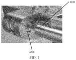
- FIG. 7shows another view of the assembly of FIG. 5 .
- FIG. 8shows a disassembled view of a targeting guide and post in accordance with the present invention.
- FIG. 9shows an assembled view of a targeting guide and post in accordance with the present invention.
- FIG. 10shows an assembled view of a targeting guide and post in accordance with the present invention.
- FIG. 11shows an assembled view of a targeting guide and post rotating about the post in accordance with the present invention.
- FIG. 11shows a reamer over the k-wire of FIG. 10 .
- FIG. 12shows a depth measuring probe in accordance with the present invention.
- FIG. 13shows a close-up view of FIG. 12 .
- FIG. 14shows the targeting guide of FIG. 5 .
- FIG. 15shows the targeting guide, implant post, and implant post fastener of FIG. 8 .
- FIG. 16shows the targeting guide, implant post, and implant post fastener of FIG. 15 with the post engaged with the fastener.
- FIG. 17shows the targeting guide, implant post, and implant post fastener of FIG. 15 with a hole of the targeting guide aligning with a hole of the post.
- FIG. 18shows the targeting guide, implant post, and implant post fastener of FIG. 17 with different holes of the targeting guide post aligned.
- FIG. 19shows a k-wire in bone after removal of the post drill guide of FIG. 4 .
- FIG. 20shows a reamer over the k-wire of FIG. 19 .
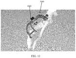
- FIG. 21shows a close-up view of a reamer over the k-wire of FIG. 20 .
- FIG. 22shows a targeting guide and implant post assembly of FIG. 18 with the post received in a reamed hole in the bone.
- FIG. 23shows a close-up view of the post received in the bone of FIG. 22 .
- FIG. 24shows another view of the targeting guide and implant post of FIG. 22 manipulating the metatarsal.
- FIG. 25shows the targeting guide and implant post of FIG. 22 with the wires in the bone manipulating the bone angle.
- FIG. 26shows a screwdriver engaging a screw of the compression distraction fixture of FIG. 25 .
- FIG. 27shows a targeting guide, bushing, and drill bit in accordance with the present invention.
- FIG. 28shows the targeting guide and drill bit of FIG. 27 with the drill bit engaged with the targeting guide.
- FIG. 29is a side view showing the drill bit extending toward the post of FIG. 28 .
- FIG. 30shows a depth probe engaging a bushing of FIG. 28 .
- FIG. 31shows a close-up view of the depth probe of FIG. 30 .
- FIG. 32shows the targeting guide of FIG. 28 with a screw inserted into a tunnel in the bone.
- FIG. 33shows the targeting guide and screw of FIG. 31 with the screw advanced.
- FIG. 34shows a post plug in accordance with the present invention.
- an orthopedic device 1000is implanted into a human foot to correct a deformity.
- the present inventioncomprises surgical instruments and methods for properly placing implant 1000 into a medial cuneiform of the human foot in a manner that maximizes the amount of bone surrounding the implant by targeting the major axis of the cross section of the bone.
- implant 1000includes two or more solid shafted screws 1100 .
- Solid shaftedmeans that the portion of the screw that crosses the joint is not threaded and is at the major diameter of the distal screw thread.
- Screws 1100cross the medial cuneiform/first metatarsal joint and lock into a post 1200 .
- Locking screws 1100 into post 1200requires seating the screws 1100 to a terminal thread thereof into post 1200 such that the posts have reached an end of potential advancement. In such a locked state, screws 1100 cannot move (translate or rotate) with respect to post 1200 or each other.
- post 1200has a diameter of 1.5 to 2.5 times a diameter of screws 1100 .
- Heads 1105 of the screws 1100are substantially tapered, “headless screws,” allowing them to be seated further into bone than a headed screw.
- implant post 1200 of implant 1000comprises a substantially cylindrical shape having a longitudinal axis 1210 and threaded holes 1220 at predefined angles relative to the longitudinal axis 1210 of post 1200 .
- Post 1200is configured to be releasably connected (eliminating rotation and translation with respect to) to a targeting guide 3000 ( FIG. 8 ) that directs instrumentation to the threaded holes 1220 .
- targeting guide 3000may be releasable from the post by removing a post fastener.
- the postmay also be configured to receive a post plug to prevent bone growth into connection threads of the post (i.e., to allow easy removal).
- a post drill guide 2000 for post 1200includes positioning paddles 2100 and 2200 respectively locatable in an articular space between a medial cuneiform and a first metatarsal of the foot and in a space between a lateral side of the medial cuneiform and a superior surface of the medial cuneiform.
- Guide 2000is configured to maximize an amount of bone surrounding implant post 1200 when post 1200 is implanted into the medial cuneiform of the foot by targeting the major axis of the cross section of the bone.
- the guidehas positioning features (i.e., paddles 2100 , 2200 ) located at the articular space between the medial cuneiform and the First Metatarsal, the lateral side of the medial cuneiform, and the superior surface of the medial cuneiform.
- Guide 2000also contains a bore 2300 for receiving a k-wire 2400 .
- the K-wire drillis used to confirm correct placement on X-ray, and as a guide for a reamer that created the appropriate bore for implant post 1200 to be placed as described below.
- a targeting guide 3000includes compression-distraction fixture 4000 .
- Targeting guide 3000contains a plurality of bores 3325 configured for a k-wire drill that directs placement of the k-wires in locations that do not interfere with screws 1100 .
- Targeting guide 3000may also rest against the metatarsal, aiding in the positioning of the guide, as well as the positioning of the first metatarsal.
- compress-distraction fixture 4000comprises a housing 4100 to hold a compression screw 4200 at a pitch that transmits rotational movement of the screw 4200 into translational movement of the housing 4100 by interfacing with a threaded rack 3100 of targeting guide 3000 and housing 4100 of compression distraction fixture 4000 .
- targeting guide 3000comprises a linear base 3200 having a threaded rack 3100 .
- Compression-distraction fixture 4000is attached to rack 3100 such that compression-distraction fixture 4000 is movable along rack 3100 by actuating screw 4200 ( FIG. 7 ) manipulated by a screwdriver, for example.
- targeting guide 3000is preferably pre-assembled to implant 1000 .
- built-in compression-distraction fixture 4000allows simplified joint preparation and pre-compression of the joint prior to placement of implant 1000 .
- Targeting guide 3000is preferably positioned substantially medial and dorsal to the bones being fused thereby reducing interference with X-ray imaging during procedure.
- post 1200 and targeting guide 3000when assembled, are rotatable around longitudinal axis 1210 ( FIG. 2 ) of post 1200 when post 1200 is inserted in a bone to optimize a trajectory and a start location of implanted crossing screws 1100 with respect to the bone.
- Post 1200is removably attached to targeting guide 3000 by a post fastener 1500 ( FIG. 12 ).
- Post 1200is further configured to receive a post plug 1400 ( FIG. 36 ) to prevent bone growth into the connection threads of post 1200 for easy removal.
- an implant depth probe 5000is configured to measure a distance between a surface of the bone and a back of targeting guide 3000 to provide surgeons an ideal length of screw 1100 to use.
- a distal tip of depth probe 5000is configured to be more acute than the surface of the bone with respect to a long axis of depth probe 5000 .
- the distal tip of depth probe 5000always contacts the most proximal aspect of the drilled hole, and depth probe 5000 naturally rotates with pressure applied to a grasping end of depth probe 5000 .
- an exemplary surgical technique in accordance with the present invention for placing implant 1000 ( FIG. 1 ) in bonebegins with preparing instrumentation by first ensuring a top line 4005 of compression distraction fixture 4000 is aligned with a start line 3005 of targeting guide 3000 .
- a screwdriveris used to rotate screw 4200 , causing compression-distraction fixture 4000 to travel along rack 3100 of targeting guide 3000 . Improper alignment may restrict potential distraction and compression travel of the compression-distraction fixture 4000 .
- implant post 1200may be assembled to targeting guide 3000 by threading post fastener 1500 into implant post 1200 , with targeting guide 3000 positioned between. After firm hand tightening of post fastener 1500 , there should be no gap or play between the components.
- siting holes 3300may be located in targeting guide 3000 , alignment can be visualized to ensure proper assembly and left/right foot selection.
- a medial hole 3305 of siting holes 3300 of the targeting guidemay align with a plantar hole 3307 in post 1200 as depicted in FIG. 17 .
- a lateral hole 3308 of siting holes 3300 of the targeting guidealigns with a dorsal hole 3310 of the post as depicted in FIG. 18 .
- a surgeonmay then perform soft tissue releases to ensure full mobility of a first metatarsal to a desired correction position and makes a dorsal incision over a tarsometatarsal joint.
- post drill guide 2000may be positioned so that largest paddle 2100 is between the medial cuneiform and the first metatarsal and smaller paddle 2200 is between the medial cuneiform and the second metatarsal.
- a k-wire 2400may be placed through bore 2300 of post drill guide 2000 and into the bone. Next, the surgeon may remove post drill guide 2000 , leaving k-wire 2400 in the bone as shown in FIG. 19 .
- the surgical techniquefurther comprises inserting a reamer 2405 over k-wire 2400 and drilling until the depth line on the drill bit is at or just below bone surface.
- the surgeonnext inserts post 1200 and targeting guide 3000 assembly into the previously reamed hole located in the medial cuneiform. The surgeon then fully seats post 1200 into the bone ensuring targeting guide 3000 depth lines are at or just below bone surface.
- FIG. 24depicts a surgeon manipulating targeting guide 3000 such that fixture 4000 applies pressure to the metatarsal to correct any frontal plane deformity.
- two k-wires 145e.g., two 2 mm k-wires
- the k-wirescould be smooth or threaded.
- a Steinman pinmay be substituted for each k-wire.
- the surgeonmay pivot targeting guide 3000 and manipulate the metatarsal to correct a bone angle. Once the metatarsal is in the desired location, the surgeon can lock the correction by inserting a k-wire 150 through a hole 3100 of guide 3000 and into the metatarsal but proximal to post 1200 .
- a driver 160e.g., a T10 driver
- a driver 160may be utilized to turn screw 4200 in compression-distraction fixture 4000 counter-clockwise to distract the first tarsometatarsal joint.
- the surgeonmay prepare the joint with curettage, microfracture, and other preferred bone preparation methods.
- screw 4200is turned clockwise to compress the metatarsal to the medial cuneiform.
- the surgeonplaces a bushing 175 into medial hole 3305 in the targeting guide 3000 .
- the bushingmay be chosen to be the longest bushing that will fully seat against guide 3000 without touching the metatarsal.
- a drill bit 170e.g., a 3.6 mm drill bit
- the surgeonintroduces a drill bit 170 (e.g., a 3.6 mm drill bit) into bushing 175 and fully seats drill bit 170 against bushing 175 (up to a step on the drill bit) to ensure that the drill creates a continuous tunnel of an appropriate length to post 1200 .
- a drill bit 170e.g., a 3.6 mm drill bit
- bushing 175may be removed and a depth measuring probe 5000 may be inserted through a hole (e.g., hole 3305 ) in targeting guide 3000 and into the tunnel previously created until the probe 5000 contacts bone (i.e., at the end of the tunnel).
- a measurementmay be read at an outside guide surface 5005 ( FIG. 31 ) which correlates with a suggested screw length.
- the surgeonselects a screw 1100 and inserts the same through the pre-drilled tunnel until it reaches post 1200 or the rear screw head reaches the bone as depicted in FIG. 32 . Then, the surgeon rotationally advances screw 1100 until the desired depth is achieved ( FIG. 33 ). This process is repeated as necessary ( FIGS. 32-33 ).
- the surgeonmay reduce the compression by turning screw 4200 counter-clockwise and removing all three k-wires (e.g., wire 150 , wires 145 ).
- the surgeonmay release post fastener 1500 from post 1200 and remove targeting guide 3000 . Once both screws 1100 are locked into post 1200 , the surgeon may thread a post screw 1300 into the top of the post ( FIG. 34 ).
- the screws described abovemay be driven by a screwdriver operated by a surgeon.
- a screwdrivermay be configured with an alignment feature which includes a cylindrical feature at the tip of the driver, smaller than the feature that generates torque, that inserts into a cylindrical hole feature at the bottom of the screw's drive feature.
- This alignment featureis important to ensure that the axis of the screw and the axis of the driver are colinear. This prevents the screw from deviating from the drilled tunnel (in soft bone) and missing the holes in the post.
- the screwis configured to be minimally retained with the driver, such that it need not be held to the driver during insertion (i.e., so it doesn't fall off of the driver).
Landscapes
- Health & Medical Sciences (AREA)
- Surgery (AREA)
- Life Sciences & Earth Sciences (AREA)
- Orthopedic Medicine & Surgery (AREA)
- Biomedical Technology (AREA)
- Public Health (AREA)
- Veterinary Medicine (AREA)
- Engineering & Computer Science (AREA)
- Nuclear Medicine, Radiotherapy & Molecular Imaging (AREA)
- Heart & Thoracic Surgery (AREA)
- Medical Informatics (AREA)
- Molecular Biology (AREA)
- Animal Behavior & Ethology (AREA)
- General Health & Medical Sciences (AREA)
- Neurology (AREA)
- Oral & Maxillofacial Surgery (AREA)
- Dentistry (AREA)
- Pathology (AREA)
- Surgical Instruments (AREA)
Abstract
Description
Claims (18)
Priority Applications (1)
| Application Number | Priority Date | Filing Date | Title |
|---|---|---|---|
| US16/221,036US11000327B2 (en) | 2018-12-14 | 2018-12-14 | Bone defect repair apparatus and method |
Applications Claiming Priority (1)
| Application Number | Priority Date | Filing Date | Title |
|---|---|---|---|
| US16/221,036US11000327B2 (en) | 2018-12-14 | 2018-12-14 | Bone defect repair apparatus and method |
Publications (2)
| Publication Number | Publication Date |
|---|---|
| US20200188003A1 US20200188003A1 (en) | 2020-06-18 |
| US11000327B2true US11000327B2 (en) | 2021-05-11 |
Family
ID=71072245
Family Applications (1)
| Application Number | Title | Priority Date | Filing Date |
|---|---|---|---|
| US16/221,036Active2039-07-11US11000327B2 (en) | 2018-12-14 | 2018-12-14 | Bone defect repair apparatus and method |
Country Status (1)
| Country | Link |
|---|---|
| US (1) | US11000327B2 (en) |
Cited By (4)
| Publication number | Priority date | Publication date | Assignee | Title |
|---|---|---|---|---|
| WO2021206905A1 (en)* | 2020-04-09 | 2021-10-14 | Wright Medical Technology, Inc. | Targeting guide and methods of using the targeting guide |
| US20220401139A1 (en)* | 2021-06-17 | 2022-12-22 | Wright Medical Technology, Inc. | Minimally invasive surgery osteotomy fragment shifter, stabilizer, and targeter |
| US11931106B2 (en) | 2019-09-13 | 2024-03-19 | Treace Medical Concepts, Inc. | Patient-specific surgical methods and instrumentation |
| US11986251B2 (en) | 2019-09-13 | 2024-05-21 | Treace Medical Concepts, Inc. | Patient-specific osteotomy instrumentation |
Families Citing this family (8)
| Publication number | Priority date | Publication date | Assignee | Title |
|---|---|---|---|---|
| CA2702952C (en) | 2007-10-27 | 2017-01-03 | Parcus Medical, Llc | Suture anchor |
| WO2015171962A1 (en) | 2014-05-07 | 2015-11-12 | Bart Bracy | Multipart suture |
| US11517301B2 (en) | 2016-06-02 | 2022-12-06 | Parcus Medical, Llc | Surgical tool and method of use |
| WO2017210620A1 (en) | 2016-06-02 | 2017-12-07 | Bracy Barton | Suture tool and method of use |
| US11000327B2 (en)* | 2018-12-14 | 2021-05-11 | Nextremity Solutions, Inc. | Bone defect repair apparatus and method |
| WO2021247498A1 (en) | 2020-06-01 | 2021-12-09 | Pmo Llc | Bone deformity treatment system, device, and related methods |
| US11439415B2 (en)* | 2020-11-18 | 2022-09-13 | Fusion Orthopedics USA, LLC | Osteotomy cutting systems and surgical techniques |
| AU2022276540A1 (en)* | 2021-05-20 | 2023-11-30 | Treace Medical Concepts, Inc. | Cut guide with integrated joint realignment features |
Citations (86)
| Publication number | Priority date | Publication date | Assignee | Title |
|---|---|---|---|---|
| US2614559A (en) | 1950-09-06 | 1952-10-21 | Herman H Livingston | Intramedullary bar |
| US4016874A (en) | 1976-05-19 | 1977-04-12 | Maffei Ernest J | Three-part intramedullary bone-setting pin |
| US4541424A (en) | 1982-03-30 | 1985-09-17 | Howmedica International, Inc. | Distal aiming device for a locking nail |
| US4622959A (en) | 1985-03-05 | 1986-11-18 | Marcus Randall E | Multi-use femoral intramedullary nail |
| US5295991A (en) | 1991-05-24 | 1994-03-22 | Synthes (U.S.A.) | Surgical instrument for positioning osteosynthetic elements |
| US5411504A (en) | 1993-08-02 | 1995-05-02 | Vilas; John W. | Drill jig for animal prosthesis insertion |
| US5474561A (en) | 1994-02-01 | 1995-12-12 | Yao; Meei-Huei | All positional and universal guiding device for interlocking intramedullary nail |
| US5480402A (en) | 1993-08-05 | 1996-01-02 | Kim; Andrew C. | Shoulder compression interlocking system |
| US6030391A (en)* | 1998-10-26 | 2000-02-29 | Micropure Medical, Inc. | Alignment gauge for metatarsophalangeal fusion surgery |
| US6093192A (en) | 1998-04-24 | 2000-07-25 | Aap Implanate Aktiengesellschaft | Target device for proximal and distal locking of medullary nails without X-rays |
| US6210414B1 (en) | 2000-04-20 | 2001-04-03 | Chin Lin | Bone fastener for shinbone and thighbone |
| US6517541B1 (en) | 1998-12-23 | 2003-02-11 | Nenad Sesic | Axial intramedullary screw for the osteosynthesis of long bones |
| US20030073999A1 (en) | 2001-10-12 | 2003-04-17 | Putnam Matthew D. | Intramedullary rod for wrist fixation |
| US6579293B1 (en) | 2000-08-02 | 2003-06-17 | Rama E. Chandran | Intramedullary rod with interlocking oblique screw for tibio-calcaneal arthrodesis |
| US20030135216A1 (en) | 2000-05-25 | 2003-07-17 | Sevrain Lionel C. | Anchoring system for fixing objects to bones |
| US6620195B2 (en) | 2001-04-18 | 2003-09-16 | Medicinelodge, Inc. | Apparatus and method for attaching a graft ligament to a bone |
| US20050055023A1 (en) | 2002-07-23 | 2005-03-10 | Advanced Orthopaedic Solutions, Inc. | Intramedullary nail for long bone fractures |
| US20050107791A1 (en) | 2003-11-14 | 2005-05-19 | Manderson Easton L. | Intramedullary locked compression screw for stabiliziation and union of complex ankle and subtalar deformities |
| US20050283154A1 (en) | 2000-02-01 | 2005-12-22 | Orbay Jorge L | Intramedullary fixation device for metaphyseal long bone fractures |
| US20060015123A1 (en) | 2004-07-15 | 2006-01-19 | Wright Medical Technology, Inc. | Guide assembly for intramedullary fixation and method of using the same |
| US20060122600A1 (en) | 1999-06-10 | 2006-06-08 | Orthodyne, Inc. | Femoral intramedullary rod system |
| WO2006091460A1 (en) | 2005-02-18 | 2006-08-31 | Smith & Nephew, Inc. | Hindfoot nail |
| US7169149B1 (en) | 2003-07-24 | 2007-01-30 | Phoenix Orthopaedic Corporation | Device for external fixation of a proximal fracture of the ulna with a clamped medullar pin and multiple clamped pins holding bone fragments |
| US7179259B1 (en) | 2004-06-04 | 2007-02-20 | Biomet Manufacturing Corp. | Instrument assembly for lateral implant |
| WO2007138062A1 (en) | 2006-05-31 | 2007-12-06 | Aesculap Ag & Co. Kg | Implant with a fixing element |
| US7311710B2 (en) | 2002-08-01 | 2007-12-25 | Stryker Trauma Gmbh | Targeting device for a locking nail |
| US20080077132A1 (en) | 2006-09-25 | 2008-03-27 | Medoff Robert J | Bone fixation device having integral fixation member |
| US20080147066A1 (en) | 2006-12-19 | 2008-06-19 | Zimmer Technology, Inc. | Bone fixing system |
| US20090036931A1 (en)* | 2007-08-04 | 2009-02-05 | Normed Medizin-Technik Vertriebs-Gmbh | Foot surgery bone plate, and system comprising bone plate and insertion aid |
| US20090149861A1 (en)* | 2005-05-13 | 2009-06-11 | Newdeal | Joint fusion apparatus for the ankle-type joint and arthrodetic pin for use in said apparatus |
| US20090157077A1 (en) | 2007-12-17 | 2009-06-18 | Wright Medical Technology, Inc. | Guide assembly for intramedullary fixation and method of using the same |
| US20100036440A1 (en) | 2008-08-11 | 2010-02-11 | Arch Day Design, Llc | Collapsible bone screw apparatus |
| WO2010033702A2 (en) | 2008-09-17 | 2010-03-25 | Skeletal Dynamics Llc | Intramedullary arthrodesis nail and method of use |
| US20100114315A1 (en) | 2008-10-31 | 2010-05-06 | Manderson Easton L | Intramedullary locked compression screw for stabilization and union of complex ankle and subtalar deformities |
| US7713291B2 (en) | 2001-10-03 | 2010-05-11 | Vaughan Medical Technologies, Inc. | Vertebral stabilization assembly and method |
| US20110125153A1 (en) | 2008-06-24 | 2011-05-26 | Jeff Tyber | Intramedullary fixation assembly and method of use |
| US20110160728A1 (en) | 2009-12-31 | 2011-06-30 | Amei Technologies, Inc. | Intramedullary Compression Nail and Related Method for Jones Fractures |
| US20110230884A1 (en) | 2008-06-24 | 2011-09-22 | Adam Mantzaris | Hybrid intramedullary fixation assembly and method of use |
| US20110245885A1 (en)* | 2009-10-15 | 2011-10-06 | Sean Powell | Protection Sleeve Retention Device |
| US8157803B1 (en) | 2007-08-21 | 2012-04-17 | Surgical Implant Generation Network | Bone fixation using an intramedullary nail interlocked with a buttress member |
| US20120095560A1 (en)* | 2010-01-13 | 2012-04-19 | Jcbd, Llc | Systems for and methods of fusing a sacroiliac joint |
| US8187281B2 (en) | 2007-10-10 | 2012-05-29 | Ebi, Llc | Variable angle targeting device |
| US8257361B2 (en)* | 2005-02-22 | 2012-09-04 | Smith & Nephew, Inc. | Instrument for fracture fragment alignment and stabilization |
| US20120277745A1 (en)* | 2009-04-21 | 2012-11-01 | Emmanuel Lizee | Systems and methods for positioning a foot in ankle arthrodesis |
| US8303589B2 (en) | 2008-06-24 | 2012-11-06 | Extremity Medical Llc | Fixation system, an intramedullary fixation assembly and method of use |
| US8313487B2 (en) | 2008-06-24 | 2012-11-20 | Extremity Medical Llc | Fixation system, an intramedullary fixation assembly and method of use |
| US8328806B2 (en) | 2008-06-24 | 2012-12-11 | Extremity Medical, Llc | Fixation system, an intramedullary fixation assembly and method of use |
| US20120330313A1 (en) | 2010-12-03 | 2012-12-27 | Grady John F | Intramedullary nail technology |
| US8343199B2 (en) | 2008-06-24 | 2013-01-01 | Extremity Medical, Llc | Intramedullary fixation screw, a fixation system, and method of fixation of the subtalar joint |
| US20130030446A1 (en)* | 2010-04-20 | 2013-01-31 | Wayne Jennifer S | Tibiotalar arthrodesis guide |
| US8468071B2 (en) | 2000-08-01 | 2013-06-18 | Jpmorgan Chase Bank, N.A. | Processing transactions using a register portion to track transactions |
| US20130245626A1 (en) | 2011-09-08 | 2013-09-19 | Abraham Lavi | Intramedullary Nail and Nail Combinations |
| US20130325006A1 (en) | 2012-05-30 | 2013-12-05 | Acumed Llc | Articulated intramedullary nail |
| US8679119B2 (en) | 2006-05-24 | 2014-03-25 | Felipe Lopez-Oliva Munoz | Locking nail system for arthrodesis reconstruction in calcaneus fractures |
| US20140243827A1 (en) | 2008-05-07 | 2014-08-28 | Tornier | Surgical technique and apparatus for proximal humeral fracture repair |
| US8821546B2 (en) | 2007-11-06 | 2014-09-02 | Stanus Investments, Inc. | Vertebral screw arrangement with locking pin |
| US20150032168A1 (en)* | 2012-02-16 | 2015-01-29 | Paragon 28, Inc. | Charco-resis implant, alignment instrument, system and method of use |
| USD722380S1 (en) | 2012-07-09 | 2015-02-10 | Del Palma Orthopedics, LLC | Bone fusion implant |
| US9017329B2 (en) | 2008-06-24 | 2015-04-28 | Extremity Medical, Llc | Intramedullary fixation assembly and method of use |
| US9044282B2 (en) | 2008-06-24 | 2015-06-02 | Extremity Medical Llc | Intraosseous intramedullary fixation assembly and method of use |
| US9107709B2 (en) | 2013-06-07 | 2015-08-18 | Stryker Trauma Gmbh | Targeting adjustment |
| US20150265323A1 (en) | 2014-03-21 | 2015-09-24 | Biomet C.V. | Intramedullary device with compound fastener trajectories |
| US9289220B2 (en) | 2008-06-24 | 2016-03-22 | Extremity Medical Llc | Intramedullary fixation assembly and method of use |
| US9421103B2 (en) | 2012-04-05 | 2016-08-23 | Orthohelix Surgical Designs, Inc. | Lateral ankle fusion plate system and jig, and method for use therewith |
| US9603640B2 (en) | 2011-01-26 | 2017-03-28 | Nextremity Solutions, Inc. | Lower extremity fusion devices and methods |
| US9622805B2 (en)* | 2015-08-14 | 2017-04-18 | Treace Medical Concepts, Inc. | Bone positioning and preparing guide systems and methods |
| US9662221B2 (en)* | 2011-01-26 | 2017-05-30 | Nextremity Solutions, Inc. | Upper extremity fusion devices and methods |
| US20170164989A1 (en)* | 2014-08-28 | 2017-06-15 | Nextremity Solutions, Inc. | Proximal bunion resection guides and plates and methods of use |
| US9814474B2 (en) | 2014-01-07 | 2017-11-14 | Nextremity Solutions, Inc. | Resection guides, implants and methods |
| US9907562B2 (en)* | 2013-03-15 | 2018-03-06 | Paragon 28, Inc. | Intramedullary nail fixation guides, devices and methods of use |
| US9936995B2 (en) | 2012-12-28 | 2018-04-10 | Paragon 28, Inc. | Alignment guide apparatus, method and system |
| US9943347B2 (en) | 2014-07-22 | 2018-04-17 | Virginia Commonwealth University | Medial column (MECO) fixation device, method, and system |
| US20180242988A1 (en)* | 2017-02-27 | 2018-08-30 | Paragon 28, Inc. | Targeting instruments, systems and methods of use |
| WO2018157168A1 (en) | 2017-02-27 | 2018-08-30 | Paragon 28, Inc. | Intramedullary nail alignment guides, fixation guides, devices, systems, and methods of use |
| WO2018183875A1 (en) | 2017-03-30 | 2018-10-04 | Paragon 28, Inc. | Bone fixation system, assembly, implants, devices, alignment guides, and methods of use |
| WO2018183884A1 (en) | 2017-03-31 | 2018-10-04 | Paragon 28, Inc. | Bone fixation system, assembly, devices, insertion guides, and methods of use |
| WO2018202782A2 (en) | 2017-05-04 | 2018-11-08 | Orthofix S.R.L. | Targeting system for the guided insertion of a guide wire or a bone screw |
| WO2019027821A1 (en) | 2017-08-04 | 2019-02-07 | Wright Medical Technology, Inc. | Screw targeting guide system and method |
| US20190117238A1 (en)* | 2017-10-20 | 2019-04-25 | Andrew Levitt | Percutaneous Metatarsal Fixation Guide and Methods of Use |
| US20190125418A1 (en)* | 2017-10-27 | 2019-05-02 | Wright Medical Technology, Inc. | Implant with intramedullary portion and offset extramedullary portion |
| US10342590B2 (en)* | 2015-08-14 | 2019-07-09 | Treace Medical Concepts, Inc. | Tarsal-metatarsal joint procedure utilizing fulcrum |
| US20190274745A1 (en)* | 2015-07-14 | 2019-09-12 | Treace Medical Concepts, Inc. | Bone positioning guide |
| US20190328436A1 (en) | 2015-08-14 | 2019-10-31 | Treace Medical Concepts, Inc. | Tarsal-metatarsal joint procedure utilizing fulcrum |
| US20200188003A1 (en)* | 2018-12-14 | 2020-06-18 | Nextremity Solutions, Inc. | Bone defect repair apparatus and method |
| US20200253641A1 (en)* | 2019-02-13 | 2020-08-13 | Treace Medical Concepts, Inc. | Tarsal-metatarsal joint procedure utilizing compressor-distractor and instrument providing sliding surface |
| US20200281637A1 (en)* | 2019-03-05 | 2020-09-10 | Nextremity Solutions, Inc. | Bone defect repair apparatus and method |
- 2018
- 2018-12-14USUS16/221,036patent/US11000327B2/enactiveActive
Patent Citations (111)
| Publication number | Priority date | Publication date | Assignee | Title |
|---|---|---|---|---|
| US2614559A (en) | 1950-09-06 | 1952-10-21 | Herman H Livingston | Intramedullary bar |
| US4016874A (en) | 1976-05-19 | 1977-04-12 | Maffei Ernest J | Three-part intramedullary bone-setting pin |
| US4541424A (en) | 1982-03-30 | 1985-09-17 | Howmedica International, Inc. | Distal aiming device for a locking nail |
| US4622959A (en) | 1985-03-05 | 1986-11-18 | Marcus Randall E | Multi-use femoral intramedullary nail |
| US5295991A (en) | 1991-05-24 | 1994-03-22 | Synthes (U.S.A.) | Surgical instrument for positioning osteosynthetic elements |
| US5411504A (en) | 1993-08-02 | 1995-05-02 | Vilas; John W. | Drill jig for animal prosthesis insertion |
| US5480402A (en) | 1993-08-05 | 1996-01-02 | Kim; Andrew C. | Shoulder compression interlocking system |
| US5474561A (en) | 1994-02-01 | 1995-12-12 | Yao; Meei-Huei | All positional and universal guiding device for interlocking intramedullary nail |
| US6093192A (en) | 1998-04-24 | 2000-07-25 | Aap Implanate Aktiengesellschaft | Target device for proximal and distal locking of medullary nails without X-rays |
| US6030391A (en)* | 1998-10-26 | 2000-02-29 | Micropure Medical, Inc. | Alignment gauge for metatarsophalangeal fusion surgery |
| US6517541B1 (en) | 1998-12-23 | 2003-02-11 | Nenad Sesic | Axial intramedullary screw for the osteosynthesis of long bones |
| US20060122600A1 (en) | 1999-06-10 | 2006-06-08 | Orthodyne, Inc. | Femoral intramedullary rod system |
| US20050283154A1 (en) | 2000-02-01 | 2005-12-22 | Orbay Jorge L | Intramedullary fixation device for metaphyseal long bone fractures |
| US6210414B1 (en) | 2000-04-20 | 2001-04-03 | Chin Lin | Bone fastener for shinbone and thighbone |
| US20030135216A1 (en) | 2000-05-25 | 2003-07-17 | Sevrain Lionel C. | Anchoring system for fixing objects to bones |
| US8468071B2 (en) | 2000-08-01 | 2013-06-18 | Jpmorgan Chase Bank, N.A. | Processing transactions using a register portion to track transactions |
| US6579293B1 (en) | 2000-08-02 | 2003-06-17 | Rama E. Chandran | Intramedullary rod with interlocking oblique screw for tibio-calcaneal arthrodesis |
| US6620195B2 (en) | 2001-04-18 | 2003-09-16 | Medicinelodge, Inc. | Apparatus and method for attaching a graft ligament to a bone |
| US7713291B2 (en) | 2001-10-03 | 2010-05-11 | Vaughan Medical Technologies, Inc. | Vertebral stabilization assembly and method |
| US20030073999A1 (en) | 2001-10-12 | 2003-04-17 | Putnam Matthew D. | Intramedullary rod for wrist fixation |
| US20050055023A1 (en) | 2002-07-23 | 2005-03-10 | Advanced Orthopaedic Solutions, Inc. | Intramedullary nail for long bone fractures |
| US7311710B2 (en) | 2002-08-01 | 2007-12-25 | Stryker Trauma Gmbh | Targeting device for a locking nail |
| US7169149B1 (en) | 2003-07-24 | 2007-01-30 | Phoenix Orthopaedic Corporation | Device for external fixation of a proximal fracture of the ulna with a clamped medullar pin and multiple clamped pins holding bone fragments |
| US20050107791A1 (en) | 2003-11-14 | 2005-05-19 | Manderson Easton L. | Intramedullary locked compression screw for stabiliziation and union of complex ankle and subtalar deformities |
| US7179259B1 (en) | 2004-06-04 | 2007-02-20 | Biomet Manufacturing Corp. | Instrument assembly for lateral implant |
| US20060015123A1 (en) | 2004-07-15 | 2006-01-19 | Wright Medical Technology, Inc. | Guide assembly for intramedullary fixation and method of using the same |
| US20090292292A1 (en) | 2004-07-15 | 2009-11-26 | Wright Medical Technology, Inc. | Guide assembly for intramedullary fixation and method of using the same |
| US8034056B2 (en) | 2004-07-15 | 2011-10-11 | Wright Medical Technology, Inc. | Guide assembly for intramedullary fixation and method of using the same |
| WO2006091460A1 (en) | 2005-02-18 | 2006-08-31 | Smith & Nephew, Inc. | Hindfoot nail |
| US8257361B2 (en)* | 2005-02-22 | 2012-09-04 | Smith & Nephew, Inc. | Instrument for fracture fragment alignment and stabilization |
| US20090149861A1 (en)* | 2005-05-13 | 2009-06-11 | Newdeal | Joint fusion apparatus for the ankle-type joint and arthrodetic pin for use in said apparatus |
| US8679119B2 (en) | 2006-05-24 | 2014-03-25 | Felipe Lopez-Oliva Munoz | Locking nail system for arthrodesis reconstruction in calcaneus fractures |
| WO2007138062A1 (en) | 2006-05-31 | 2007-12-06 | Aesculap Ag & Co. Kg | Implant with a fixing element |
| US20080077132A1 (en) | 2006-09-25 | 2008-03-27 | Medoff Robert J | Bone fixation device having integral fixation member |
| US20080147066A1 (en) | 2006-12-19 | 2008-06-19 | Zimmer Technology, Inc. | Bone fixing system |
| US20090036931A1 (en)* | 2007-08-04 | 2009-02-05 | Normed Medizin-Technik Vertriebs-Gmbh | Foot surgery bone plate, and system comprising bone plate and insertion aid |
| US8157803B1 (en) | 2007-08-21 | 2012-04-17 | Surgical Implant Generation Network | Bone fixation using an intramedullary nail interlocked with a buttress member |
| US8187281B2 (en) | 2007-10-10 | 2012-05-29 | Ebi, Llc | Variable angle targeting device |
| US8821546B2 (en) | 2007-11-06 | 2014-09-02 | Stanus Investments, Inc. | Vertebral screw arrangement with locking pin |
| US20090157077A1 (en) | 2007-12-17 | 2009-06-18 | Wright Medical Technology, Inc. | Guide assembly for intramedullary fixation and method of using the same |
| US20140243827A1 (en) | 2008-05-07 | 2014-08-28 | Tornier | Surgical technique and apparatus for proximal humeral fracture repair |
| US8343199B2 (en) | 2008-06-24 | 2013-01-01 | Extremity Medical, Llc | Intramedullary fixation screw, a fixation system, and method of fixation of the subtalar joint |
| US20150173811A1 (en) | 2008-06-24 | 2015-06-25 | Extremity Medical, Llc | Fixation System, An Intramedullary Fixation Assembly and Method of Use |
| US9364271B2 (en) | 2008-06-24 | 2016-06-14 | Extremity Medical Llc | Intraosseous intramedullary fixation assembly and method of use |
| US20110230884A1 (en) | 2008-06-24 | 2011-09-22 | Adam Mantzaris | Hybrid intramedullary fixation assembly and method of use |
| US9289220B2 (en) | 2008-06-24 | 2016-03-22 | Extremity Medical Llc | Intramedullary fixation assembly and method of use |
| US8303589B2 (en) | 2008-06-24 | 2012-11-06 | Extremity Medical Llc | Fixation system, an intramedullary fixation assembly and method of use |
| US8313487B2 (en) | 2008-06-24 | 2012-11-20 | Extremity Medical Llc | Fixation system, an intramedullary fixation assembly and method of use |
| US8328806B2 (en) | 2008-06-24 | 2012-12-11 | Extremity Medical, Llc | Fixation system, an intramedullary fixation assembly and method of use |
| US9615870B2 (en) | 2008-06-24 | 2017-04-11 | Extremity Medical, Llc | Intramedullary fixation assembly and method of use |
| US8920453B2 (en) | 2008-06-24 | 2014-12-30 | Extremity Medical, Llc | Fixation system, an intramedullary fixation assembly and method of use |
| US9044282B2 (en) | 2008-06-24 | 2015-06-02 | Extremity Medical Llc | Intraosseous intramedullary fixation assembly and method of use |
| US9017329B2 (en) | 2008-06-24 | 2015-04-28 | Extremity Medical, Llc | Intramedullary fixation assembly and method of use |
| US20110125153A1 (en) | 2008-06-24 | 2011-05-26 | Jeff Tyber | Intramedullary fixation assembly and method of use |
| US20180161079A1 (en) | 2008-06-24 | 2018-06-14 | Extremity Medical Llc | Intraosseous intramedullary fixation assembly and method of use |
| US9877752B2 (en) | 2008-06-24 | 2018-01-30 | Extremity Medical Llc | Intraosseous intramedullary fixation assembly and method of use |
| US8920476B2 (en) | 2008-06-24 | 2014-12-30 | Extremity Medical, Llc | Fixation system, an intramedullary fixation assembly and method of use |
| US8900274B2 (en) | 2008-06-24 | 2014-12-02 | Extremity Medical Llc | Fixation system, an intramedullary fixation assembly and method of use |
| US20100036440A1 (en) | 2008-08-11 | 2010-02-11 | Arch Day Design, Llc | Collapsible bone screw apparatus |
| WO2010033702A2 (en) | 2008-09-17 | 2010-03-25 | Skeletal Dynamics Llc | Intramedullary arthrodesis nail and method of use |
| US20100114315A1 (en) | 2008-10-31 | 2010-05-06 | Manderson Easton L | Intramedullary locked compression screw for stabilization and union of complex ankle and subtalar deformities |
| US20120277745A1 (en)* | 2009-04-21 | 2012-11-01 | Emmanuel Lizee | Systems and methods for positioning a foot in ankle arthrodesis |
| US20110245885A1 (en)* | 2009-10-15 | 2011-10-06 | Sean Powell | Protection Sleeve Retention Device |
| US20110160728A1 (en) | 2009-12-31 | 2011-06-30 | Amei Technologies, Inc. | Intramedullary Compression Nail and Related Method for Jones Fractures |
| US20120095560A1 (en)* | 2010-01-13 | 2012-04-19 | Jcbd, Llc | Systems for and methods of fusing a sacroiliac joint |
| US20130030446A1 (en)* | 2010-04-20 | 2013-01-31 | Wayne Jennifer S | Tibiotalar arthrodesis guide |
| US20120330313A1 (en) | 2010-12-03 | 2012-12-27 | Grady John F | Intramedullary nail technology |
| US20170216043A1 (en)* | 2011-01-26 | 2017-08-03 | Nextremity Solutions, Inc. | Upper extremity fusion devices and methods |
| US9603640B2 (en) | 2011-01-26 | 2017-03-28 | Nextremity Solutions, Inc. | Lower extremity fusion devices and methods |
| US9662221B2 (en)* | 2011-01-26 | 2017-05-30 | Nextremity Solutions, Inc. | Upper extremity fusion devices and methods |
| US20130245626A1 (en) | 2011-09-08 | 2013-09-19 | Abraham Lavi | Intramedullary Nail and Nail Combinations |
| US20150032168A1 (en)* | 2012-02-16 | 2015-01-29 | Paragon 28, Inc. | Charco-resis implant, alignment instrument, system and method of use |
| US9421103B2 (en) | 2012-04-05 | 2016-08-23 | Orthohelix Surgical Designs, Inc. | Lateral ankle fusion plate system and jig, and method for use therewith |
| US20160354128A1 (en) | 2012-04-05 | 2016-12-08 | Orthohelix Surgical Designs, Inc. | Lateral ankle fusion plate system and jig, and method for use therewith |
| US20130325006A1 (en) | 2012-05-30 | 2013-12-05 | Acumed Llc | Articulated intramedullary nail |
| USD722380S1 (en) | 2012-07-09 | 2015-02-10 | Del Palma Orthopedics, LLC | Bone fusion implant |
| US9936995B2 (en) | 2012-12-28 | 2018-04-10 | Paragon 28, Inc. | Alignment guide apparatus, method and system |
| US20190307498A1 (en) | 2012-12-28 | 2019-10-10 | Paragon 28, Inc. | Alignment guide apparatus, methods and systems |
| US10327829B2 (en) | 2012-12-28 | 2019-06-25 | Paragon 28, Inc. | Alignment guide apparatus, methods and systems |
| US20180193039A1 (en)* | 2013-03-15 | 2018-07-12 | Paragon 28, Inc. | Intramedullary nail fixation guides, devices, and methods of use |
| US9907562B2 (en)* | 2013-03-15 | 2018-03-06 | Paragon 28, Inc. | Intramedullary nail fixation guides, devices and methods of use |
| US9107709B2 (en) | 2013-06-07 | 2015-08-18 | Stryker Trauma Gmbh | Targeting adjustment |
| US10390844B2 (en) | 2013-06-07 | 2019-08-27 | Stryker European Holdings I, Llc | Targeting adjustment |
| US9814474B2 (en) | 2014-01-07 | 2017-11-14 | Nextremity Solutions, Inc. | Resection guides, implants and methods |
| US20150265323A1 (en) | 2014-03-21 | 2015-09-24 | Biomet C.V. | Intramedullary device with compound fastener trajectories |
| US9943347B2 (en) | 2014-07-22 | 2018-04-17 | Virginia Commonwealth University | Medial column (MECO) fixation device, method, and system |
| US20170164989A1 (en)* | 2014-08-28 | 2017-06-15 | Nextremity Solutions, Inc. | Proximal bunion resection guides and plates and methods of use |
| US10335220B2 (en) | 2015-07-14 | 2019-07-02 | Treace Medical Concepts, Inc. | Bone positioning guide |
| US20190274745A1 (en)* | 2015-07-14 | 2019-09-12 | Treace Medical Concepts, Inc. | Bone positioning guide |
| US9936994B2 (en) | 2015-07-14 | 2018-04-10 | Treace Medical Concepts, Inc. | Bone positioning guide |
| US10849670B2 (en)* | 2015-08-14 | 2020-12-01 | Treace Medical Concepts, Inc. | Bone positioning and preparing guide systems and methods |
| US20190328436A1 (en) | 2015-08-14 | 2019-10-31 | Treace Medical Concepts, Inc. | Tarsal-metatarsal joint procedure utilizing fulcrum |
| US9622805B2 (en)* | 2015-08-14 | 2017-04-18 | Treace Medical Concepts, Inc. | Bone positioning and preparing guide systems and methods |
| US20180317992A1 (en) | 2015-08-14 | 2018-11-08 | Treace Medical Concepts, Inc. | Bone positioning and preparing guide systems and methods |
| US10342590B2 (en)* | 2015-08-14 | 2019-07-09 | Treace Medical Concepts, Inc. | Tarsal-metatarsal joint procedure utilizing fulcrum |
| US10045807B2 (en) | 2015-08-14 | 2018-08-14 | Treace Medical Concepts, Inc. | Bone positioning and preparing guide systems and methods |
| US20180242988A1 (en)* | 2017-02-27 | 2018-08-30 | Paragon 28, Inc. | Targeting instruments, systems and methods of use |
| US20180242987A1 (en) | 2017-02-27 | 2018-08-30 | Paragon 28, Inc. | Intramedullary nail alignment guides, fixation guides, devices, systems, and methods of use |
| WO2018157170A1 (en) | 2017-02-27 | 2018-08-30 | Paragon 28, Inc. | Targeting instruments, systems and methods of use |
| WO2018157168A1 (en) | 2017-02-27 | 2018-08-30 | Paragon 28, Inc. | Intramedullary nail alignment guides, fixation guides, devices, systems, and methods of use |
| US20180280069A1 (en) | 2017-03-30 | 2018-10-04 | Paragon 28, Inc. | Bone fixation system, assembly, implants, devices, alignment guides, and methods of use |
| WO2018183875A1 (en) | 2017-03-30 | 2018-10-04 | Paragon 28, Inc. | Bone fixation system, assembly, implants, devices, alignment guides, and methods of use |
| US20180289379A1 (en) | 2017-03-31 | 2018-10-11 | Paragon 28, Inc. | Bone fixation system, assembly, devices, insertion guides, and methods of use |
| WO2018183884A1 (en) | 2017-03-31 | 2018-10-04 | Paragon 28, Inc. | Bone fixation system, assembly, devices, insertion guides, and methods of use |
| WO2018202782A2 (en) | 2017-05-04 | 2018-11-08 | Orthofix S.R.L. | Targeting system for the guided insertion of a guide wire or a bone screw |
| WO2019027821A1 (en) | 2017-08-04 | 2019-02-07 | Wright Medical Technology, Inc. | Screw targeting guide system and method |
| US20190117238A1 (en)* | 2017-10-20 | 2019-04-25 | Andrew Levitt | Percutaneous Metatarsal Fixation Guide and Methods of Use |
| US20190125418A1 (en)* | 2017-10-27 | 2019-05-02 | Wright Medical Technology, Inc. | Implant with intramedullary portion and offset extramedullary portion |
| US20200188003A1 (en)* | 2018-12-14 | 2020-06-18 | Nextremity Solutions, Inc. | Bone defect repair apparatus and method |
| US20200253641A1 (en)* | 2019-02-13 | 2020-08-13 | Treace Medical Concepts, Inc. | Tarsal-metatarsal joint procedure utilizing compressor-distractor and instrument providing sliding surface |
| US20200281637A1 (en)* | 2019-03-05 | 2020-09-10 | Nextremity Solutions, Inc. | Bone defect repair apparatus and method |
Non-Patent Citations (4)
| Title |
|---|
| International Preliminary Report on Patentability for PCT Application No. PCT/US2012/022723, dated Aug. 8, 2013. |
| International Preliminary Report on Patentability for PCT Application No. PCT/US2012/022755, dated Aug. 8, 2013. |
| International Search Report for PCT/US2012/022723 dated Jul. 6, 2012. |
| International Search Report for PCT/US2012/022755 dated Jul. 6, 2012. |
Cited By (8)
| Publication number | Priority date | Publication date | Assignee | Title |
|---|---|---|---|---|
| US11931106B2 (en) | 2019-09-13 | 2024-03-19 | Treace Medical Concepts, Inc. | Patient-specific surgical methods and instrumentation |
| US11986251B2 (en) | 2019-09-13 | 2024-05-21 | Treace Medical Concepts, Inc. | Patient-specific osteotomy instrumentation |
| WO2021206905A1 (en)* | 2020-04-09 | 2021-10-14 | Wright Medical Technology, Inc. | Targeting guide and methods of using the targeting guide |
| US12414782B2 (en) | 2020-04-09 | 2025-09-16 | Wright Medical Technology, Inc. | Targeting guide and methods of using the targeting guide |
| US20220401139A1 (en)* | 2021-06-17 | 2022-12-22 | Wright Medical Technology, Inc. | Minimally invasive surgery osteotomy fragment shifter, stabilizer, and targeter |
| US12256969B2 (en)* | 2021-06-17 | 2025-03-25 | Wright Medical Technology, Inc. | Minimally invasive surgery osteotomy fragment shifter, stabilizer, and targeter |
| US12364528B2 (en) | 2021-06-17 | 2025-07-22 | Wright Medical Technology, Inc. | Minimally invasive surgery osteotomy fragment shifter, stabilizer, and targeter |
| US12419675B2 (en) | 2021-06-17 | 2025-09-23 | Wright Medical Technology, Inc. | Minimally invasive surgery osteotomy fragment shifter, stabilizer, and targeter |
Also Published As
| Publication number | Publication date |
|---|---|
| US20200188003A1 (en) | 2020-06-18 |
Similar Documents
| Publication | Publication Date | Title |
|---|---|---|
| US11000327B2 (en) | Bone defect repair apparatus and method | |
| US12295634B2 (en) | Bone fixation system, assembly, implants, devices, alignment guides, and methods of use | |
| US10987146B2 (en) | Bone defect repair apparatus and method | |
| US12396768B2 (en) | Intramedullary nail alignment guides, fixation guides, devices, systems, and methods of use | |
| US12290294B2 (en) | Bone fixation assembly, implants and methods of use | |
| US7465303B2 (en) | External fixation assembly | |
| US8267975B2 (en) | Bone screw system | |
| US9226783B2 (en) | Ankle arthrodesis nail and outrigger assembly | |
| US9289220B2 (en) | Intramedullary fixation assembly and method of use | |
| US10470782B2 (en) | Guidance system and method for bone fusion | |
| US20210259749A1 (en) | A device and method for fixation of bone fragments in an osteotomy procedure | |
| EP1952776A1 (en) | Implant for fixing two fragments of bone together in osteotomy procedures | |
| US11925364B2 (en) | Implant, alignment guides, system and methods of use | |
| US10952780B1 (en) | Method of reducing a fracture of the lateral malleolus | |
| US11617609B2 (en) | Percutaneous methods, systems, and devices for positioning a guide wire in a bone | |
| Aynardi et al. | Intramedullary screw fixation of Jones fracture: the crucial starting point and minimizing complications | |
| CN219230095U (en) | Guide device | |
| US20250186087A1 (en) | Bunion Correction Guide System and Methods | |
| CN115553907A (en) | Guider and using method |
Legal Events
| Date | Code | Title | Description |
|---|---|---|---|
| FEPP | Fee payment procedure | Free format text:ENTITY STATUS SET TO UNDISCOUNTED (ORIGINAL EVENT CODE: BIG.); ENTITY STATUS OF PATENT OWNER: SMALL ENTITY | |
| AS | Assignment | Owner name:NEXTREMITY SOLUTIONS, INC., INDIANA Free format text:ASSIGNMENT OF ASSIGNORS INTEREST;ASSIGNORS:SCHLOTTERBACK, RYAN;DENHAM, GREG;PEPPER, JOHN;SIGNING DATES FROM 20181004 TO 20181023;REEL/FRAME:047805/0971 | |
| FEPP | Fee payment procedure | Free format text:ENTITY STATUS SET TO SMALL (ORIGINAL EVENT CODE: SMAL); ENTITY STATUS OF PATENT OWNER: SMALL ENTITY | |
| STPP | Information on status: patent application and granting procedure in general | Free format text:NON FINAL ACTION MAILED | |
| STPP | Information on status: patent application and granting procedure in general | Free format text:RESPONSE TO NON-FINAL OFFICE ACTION ENTERED AND FORWARDED TO EXAMINER | |
| STPP | Information on status: patent application and granting procedure in general | Free format text:NOTICE OF ALLOWANCE MAILED -- APPLICATION RECEIVED IN OFFICE OF PUBLICATIONS | |
| STPP | Information on status: patent application and granting procedure in general | Free format text:PUBLICATIONS -- ISSUE FEE PAYMENT VERIFIED | |
| STCF | Information on status: patent grant | Free format text:PATENTED CASE | |
| CC | Certificate of correction | ||
| AS | Assignment | Owner name:ZIMMER, INC., INDIANA Free format text:ASSIGNMENT OF ASSIGNORS INTEREST;ASSIGNOR:NEXTREMITY SOLUTIONS, INC.;REEL/FRAME:060419/0764 Effective date:20220429 | |
| MAFP | Maintenance fee payment | Free format text:PAYMENT OF MAINTENANCE FEE, 4TH YR, SMALL ENTITY (ORIGINAL EVENT CODE: M2551); ENTITY STATUS OF PATENT OWNER: SMALL ENTITY Year of fee payment:4 |