US11000314B2 - Cannulated polyaxial screw - Google Patents
Cannulated polyaxial screwDownload PDFInfo
- Publication number
- US11000314B2 US11000314B2US15/723,972US201715723972AUS11000314B2US 11000314 B2US11000314 B2US 11000314B2US 201715723972 AUS201715723972 AUS 201715723972AUS 11000314 B2US11000314 B2US 11000314B2
- Authority
- US
- United States
- Prior art keywords
- end portion
- anchor member
- bone screw
- proximal end
- retainer
- Prior art date
- Legal status (The legal status is an assumption and is not a legal conclusion. Google has not performed a legal analysis and makes no representation as to the accuracy of the status listed.)
- Expired - Fee Related
Links
Images


Classifications
- A—HUMAN NECESSITIES
- A61—MEDICAL OR VETERINARY SCIENCE; HYGIENE
- A61B—DIAGNOSIS; SURGERY; IDENTIFICATION
- A61B17/00—Surgical instruments, devices or methods
- A61B17/56—Surgical instruments or methods for treatment of bones or joints; Devices specially adapted therefor
- A61B17/58—Surgical instruments or methods for treatment of bones or joints; Devices specially adapted therefor for osteosynthesis, e.g. bone plates, screws or setting implements
- A61B17/68—Internal fixation devices, including fasteners and spinal fixators, even if a part thereof projects from the skin
- A61B17/70—Spinal positioners or stabilisers, e.g. stabilisers comprising fluid filler in an implant
- A61B17/7001—Screws or hooks combined with longitudinal elements which do not contact vertebrae
- A61B17/7035—Screws or hooks, wherein a rod-clamping part and a bone-anchoring part can pivot relative to each other
- A61B17/7037—Screws or hooks, wherein a rod-clamping part and a bone-anchoring part can pivot relative to each other wherein pivoting is blocked when the rod is clamped
- A—HUMAN NECESSITIES
- A61—MEDICAL OR VETERINARY SCIENCE; HYGIENE
- A61B—DIAGNOSIS; SURGERY; IDENTIFICATION
- A61B17/00—Surgical instruments, devices or methods
- A61B17/56—Surgical instruments or methods for treatment of bones or joints; Devices specially adapted therefor
- A61B17/58—Surgical instruments or methods for treatment of bones or joints; Devices specially adapted therefor for osteosynthesis, e.g. bone plates, screws or setting implements
- A61B17/68—Internal fixation devices, including fasteners and spinal fixators, even if a part thereof projects from the skin
- A61B17/70—Spinal positioners or stabilisers, e.g. stabilisers comprising fluid filler in an implant
- A61B17/7001—Screws or hooks combined with longitudinal elements which do not contact vertebrae
- A61B17/7032—Screws or hooks with U-shaped head or back through which longitudinal rods pass
- A—HUMAN NECESSITIES
- A61—MEDICAL OR VETERINARY SCIENCE; HYGIENE
- A61B—DIAGNOSIS; SURGERY; IDENTIFICATION
- A61B17/00—Surgical instruments, devices or methods
- A61B17/56—Surgical instruments or methods for treatment of bones or joints; Devices specially adapted therefor
- A61B17/58—Surgical instruments or methods for treatment of bones or joints; Devices specially adapted therefor for osteosynthesis, e.g. bone plates, screws or setting implements
- A61B17/68—Internal fixation devices, including fasteners and spinal fixators, even if a part thereof projects from the skin
- A61B17/84—Fasteners therefor or fasteners being internal fixation devices
- A61B17/86—Pins or screws or threaded wires; nuts therefor
- A—HUMAN NECESSITIES
- A61—MEDICAL OR VETERINARY SCIENCE; HYGIENE
- A61B—DIAGNOSIS; SURGERY; IDENTIFICATION
- A61B2560/00—Constructional details of operational features of apparatus; Accessories for medical measuring apparatus
- A61B2560/04—Constructional details of apparatus
- A61B2560/0406—Constructional details of apparatus specially shaped apparatus housings
Definitions
- U.S. patent application Ser. No. 12/290,244is also a continuation-in-part of U.S. patent application Ser. No. 11/024,543, filed Dec. 20, 2004, now U.S. Pat. No. 7,204,838.
- U.S. patent application Ser. No. 12/290,244is also a continuation-in-part of U.S. patent application Ser. No. 11/140,343, filed May 2 7, 2005, now U.S. Pat. No. 7,776,067.
- U.S. patent application Ser. No. 12/290,244is also a continuation-in-part of application Ser. No. 10/986,377, filed Nov.
- the present inventionis directed to a polyaxial bone screw for use in spinal surgery and the like and especially to such a screw adapted to receive a rod member and secure the rod member to a vertebra or the like.
- Bone screws of this typemay have a fixed head relative to a shank thereof. In the fixed bone screws, the head cannot be moved relative to the shank and the rod must be favorably positioned in order for it to be placed within the head. This is sometimes very difficult or impossible to do so polyaxial bone screws are commonly used.
- the polyaxial bone screwsallow rotation of the head about the shank until a desired rotational position is achieved for the head relative to the shank after which the rod can be inserted and the position of the head eventually locked with respect to movement relative to the shank.
- the present inventionis directed to such swivel head type bone screws and, in particular, to swivel head bone screws having an open head that allows placement of the rod member within the head and then subsequent closure by use of a closure top, plug or the like to capture the rod in the head of the screw.
- the implantBecause such implants are for placement within the human body, it is always desirable for the implant to have as little effect on the body as possible. Consequently, it is quite desirable for the implants to have a relatively small profile both in height and width. It is also desirable that the implants be lightweight.
- the swivel head implantsbe unlikely to unintentionally disassemble within the body. It is very undesirable for pieces of the implant to be free to move around within the body after surgery is completed and it also assures that the implant retains an ability to correct the structural problem for which it was implanted. Furthermore, if the implant should slip or become loose for some reason, it is still desirable for all of the parts to remain together and not separate.
- the present inventionis directed to a polyaxial bone screw that comprises a shank, a head and a retainer ring that operably cooperate with each other.
- the bone screwis designed to allow the shank to be locked or secured in a selected angular configuration with respect to the head, while the head receives a rod member and while the shank is implanted in a bone, such as a vertebra or vertebral body.
- the shankhas an implant body which includes an external helically wound thread that is in turn attached by a neck to a capture end with a capture or connector type structure.
- the capture structureis positioned outside the bone in use and has a radiused and cylindrically shaped radially outer surface that has at least one radially outwardly extending non helically wound projection or spline thereon.
- the capture structurealso has an upper axially aligned and radiused dome that protrudes above the remainder of the shank and above the ring during use to manipulate the shank and to contact the rod.
- the shankincludes off axis apertures, grooves, side slots or the like for use by an installation tool with a mating configured head for driving and rotating the shank into the bone.
- the headhas a generally cylindrical shaped profile with an upwardly open U-shaped channel formed therein so as to effectively produce a lower base with two upstanding and spaced arms.
- the inner surfaces of the armshave a threadform thereon or another suitable guide and advancement structure such as a helically wound flangeform for use in closing the upper part of the channel.
- Located in the interior of the base and coaxially aligned with the headis a chamber having an interiorly facing partial spherical shaped surface.
- the chamberfurther opens onto a bottom surface of the head through a head lower wall bore forming a constricted or restrictive neck sized and shaped to allow passage of the capture structure therethrough.
- the retainer ringincludes an external partial spherical or hemispherical surface that is sized and shaped to be seated in and slidably engage the partial spherical surface within the head, both having approximately the same radius of generation.
- the ringalso has an internal, centrally located and axially extending ring bore sized and shaped to receive the capture structure of the shank therethrough.
- the ringhas a series of axially extending channels positioned about and opening into the central bore that are sized and shaped to allow sliding passage of the shank splines entirely through the ring so that the shank can be inserted through the ring while the ring is positioned within the chamber in the head.
- the channelsare not helically wound about the bore and preferably extend vertically or parallel to the axis of the ring.
- the ringfurther includes a set of recesses that are circumferentially spaced from the channels and that open onto the upper part of the ring and into the bore, but do not pass entirely through the ring and that can be entered by the splines by drawing the shank with the splines thereon axially downwardly with respect to the ring.
- the splinescan be passed upwardly or uploaded through the ring by sliding through the channels in conjunction with the remainder of the shank capture and after sliding completely through the bore, the shank is then rotated a certain number of degrees relative to the head, and then drawn back downwardly or downloaded so that the splines encounter and engage the recesses wherein the splines are captured by the ring.
- the splinespreferably have a wedge-shaped surface thereon which pushes not only downwardly, but radially outward against the retainer or capture ring when force is applied to the top of the shank.
- the ringis placed through the U-shaped channel into the chamber having the partial spherical surface and then rotated so that the ring hemispherical surface mates with and slidably engages the head partial spherical surface.
- the shank capture structureis uploaded into and extended through the ring central bore, while the splines pass through the channels.
- the shankis then rotated relative to the ring and then the shank is moved in an axially reverse direction opposed to uploading while the splines are positioned over the recesses so as to be aligned with the recesses and not aligned with the channels and so that the splines then enter the recesses.
- the ring with connected shankeffectively thereafter form a ball and socket joint with the head and allow free rotation to a selected angular configuration until later locked in the selected configuration.
- the shank, head and ringare then placed in a bone by screwing the shank body into the bone using the apertures on the top of the shank or alternative structure such as grooves or faceted surfaces on the outside of the portion of the shank extending above the ring.
- a rodis placed in the U-shaped channel and captured therein by closing the channel by use of a closure top or plug having a threadform or other external guide and advancement structure that mates with and advances along mating guide and advancement structure of the arms of the head, when the closure top is rotated.
- the closure topalso includes a break-off head that provides purchase for a tool for rotation and torqueing of the closure top to a preselected torque and that such torque is transferred and applied as pressure against the rod received in the head. Once the preselected torque is achieved, the break-off head breaks away from the closure top. Under pressure from the closure top, the rod pushes against the dome of the shank that extends above the ring and thereby urges the splines downwardly.
- the splinespush both downwardly and outwardly upon the retainer or capture ring, when force is applied to the dome, so as to frictionally engage and positively seat the retaining ring in the cavity and prevent further rotation in conjunction with the shank dome frictionally engaging the rod under pressure.
- the hemispherical surface of the ringabuttingly and frictionally mates with the integral hemispherical interior facing surface of the head, while the dome frictionally mates with the rod under pressure from the rod so as to lock the shank and ring in a selected angular configuration relative to the head.
- the shankin this manner, can be locked in a configuration selected from an infinite number of angular configurations with respect to the head.
- the objects in the present inventionare: to provide a polyaxial bone screw having a bone implantable shank that can be locked in a fixed position relative to a head of the bone screw; to provide such a bone screw having a capture or retaining ring having a partial external hemispherical surface that seats within a partial internal spherical shaped chamber surface within and integrally formed with a head of the bone screw to form a ball and socket joint and wherein the shank is securable to the retaining ring; to provide such a bone screw wherein the shank has at least one spline that extends radially outward from a capture end thereof and wherein the retaining ring has a central bore that receives the capture end while a channel opening into the bore allows the spline to slide through the ring so as to pass above the ring, at which time the shank can be rotated a select number of degrees and further wherein the retaining ring has a capture recess that receives the spline on further downward or reverse movement
- FIG. 1is an exploded perspective view of three elements of a polyaxial bone screw in accordance with the present invention, including a shank, a head, and a retaining ring.
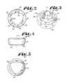
- FIG. 2is an enlarged top plan view of the retaining ring.
- FIG. 3is an enlarged perspective view of the retaining ring.
- FIG. 4is an enlarged side elevational view of the retaining ring.
- FIG. 5is an enlarged bottom plan view of the retaining ring.
- FIG. 6is an enlarged cross-sectional view of the head, taken along line 6 - 6 of FIG. 1 , illustrating the retaining ring being inserted into the head.
- FIG. 7is an enlarged cross-sectional view of the head similar to FIG. 6 , showing the retaining ring seated in the head.
- FIG. 8is a cross-sectional view of a vertebra illustrating the shank implanted therein.
- FIG. 9is an enlarged and fragmentary perspective view of the shank, head and retainer ring during assembly and just prior to the retainer ring being placed over the shank.
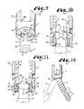
- FIG. 10is an enlarged, fragmentary and perspective cross-sectional view of the head similar to FIG. 6 , illustrating splines on a capture end of the shank that have been inserted through channels in the retainer ring and are positioned upwardly in the head above the retainer ring.
- FIG. 11is a cross-sectional view of the head, similar to FIG. 10 , showing the upper capture end of the shank with the splines lowered into receiving recesses in the ring and positioned therein.
- FIG. 12is a cross sectional view of the head and a top plan view of the shank and ring corresponding to the positioning shown in FIG. 10 .
- FIG. 13is a cross sectional view of the head and a top plan view of the shank and ring corresponding to the positioning shown in FIG. 11 .
- FIG. 14is a side elevational view of the head, ring and shank, illustrating the shank swinging or rotating from one position shown in solid lines to a second position shown in phantom lines.
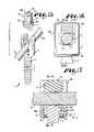
- FIG. 15is a fragmentary and partially exploded view of a complete polyaxial bone screw assembly, prior to final assembly and illustrating a rod received in the head and a closure top with a break-off head, prior to the closure top being rotatably inserted into the head.
- FIG. 16is a fragmentary and enlarged front elevational view of the bone screw assembly fully assembled and illustrating the head with the rod received therein and with the closure top fully inserted and biasing against the rod that in turn biases against the top of the shank.
- FIG. 17is an enlarged and fragmentary cross-sectional view of the bone screw assembly with rod inserted therein, taken along line 17 - 17 of FIG. 16 .
- FIG. 18is an enlarged cross-sectional view of the vertebra, head, rod and closure top, taken along line 18 - 18 of FIG. 17 showing the shank implanted in the vertebra and with the bone screw assembly in a completely assembled and operational configuration with the shank locked in an angled orientation with respect to the head.
- FIG. 19is a perspective view of a modified retainer ring of a first modified embodiment in accordance with the present invention.
- FIG. 20is a perspective view of a second modified embodiment of the present invention illustrating a cannulated shank having four splines and a hex tool engageable head for manipulating the shank.
- FIG. 21is a perspective view of a ring for use in accordance with the second modified embodiment of the invention and the shank of FIG. 20 .
- the reference number 1generally represents a polyaxial bone screw apparatus or assembly in accordance with the present invention operably utilized by implantation into a vertebra 2 and in conjunction with a longitudinal member or rod 3 so as to operably secure the rod 3 in a fixed position relative with respect to the vertebra 2 .
- the fully assembled bone screw assembly 1comprises a shank 6 , a head 7 , a retainer ring 8 and a closure top 9 .
- the shank 6is perhaps best seen in FIGS. 1 and 8 .
- the shank 6is elongate and has a lower body 15 ending in a tip 16 .
- the shank body 15has a helically wound bone implantable thread 17 extending from near the tip 16 to near the top 18 of the body 15 and extending radially outward therefrom.
- the body 15 utilizing the thread 17is implanted into the vertebra 2 , as is seen in FIG. 18 .
- the shank 6has an elongated axis of rotation generally identified by the reference letter A. It is noted that the reference to the words top and bottom as used herein refers to the alignment shown in the various drawings, as well as the normal connotations applied to such devices, and is not intended to restrict positioning of the assembly 1 in actual use.
- Axially extending outward and upward from the shank body 15is a neck 20 of reduced radius as compared to the adjacent top 18 of the body 15 .
- a capture end or structure 21operably providing a connective or capture structure free from the bone or vertebra 2 for joining with the head 7 .
- the capture structure 21has a radially outer cylindrical surface 22 .
- the cylindrical surface 22has at least one non-helically wound and radially outward extending projection or spline 24 that extends beyond the surface 22 . In the embodiment shown in FIGS. 1 through 18 , the capture structure 21 has three such splines 24 .
- the splines 24are located near an upper end 25 of the shank 6 and are equally circumferentially centered and spaced thereabout so as to be centered at approximately 120 degree intervals relative to each other.
- Each of the splines 24has a triangular shaped profile and a front wedge forming face 27 that slopes downwardly and radially inwardly from near the upper end 25 of the shank 6 .
- Also located on the shank upper end 25is a centrally located, axially extending and upwardly directed projection or dome 29 that is centrally radiused so as to have a first radius.
- the shank upper end 25still further includes at least one tool engagement aperture for engagement by a tool driving head (not shown) that is sized and shaped to fit into the apertures for both driving and rotating the shank 6 into the vertebra 2 .
- a pair of apertures 31located in spaced relationship to each other, the dome 29 and the shank axis of rotation A are located on the shank upper end 25 .
- the apertures 31extend into the shank capture structure 21 parallel to the axis A.
- the head 7has a generally cylindrical shaped profile, as is seen in FIG. 1 , although the head 7 is not a solid cylinder.
- the head 7has a base 33 with a pair of upstanding arms 34 and 35 forming a U-shaped channel 38 between the arms 34 and 35 with a lower seat 39 having substantially the same radius as the rod 3 for operably snugly receiving the rod 3 .
- Each of the arms 34 and 35has an interior surface 41 that includes a partial helically wound guide and advancement structure 42 .
- the guide and advancement structure 42is a partial helically wound flangeform which will mate under rotation with a similar structure on the closure top 9 , as described below.
- the guide and advancement structure 42could alternatively be a V-shaped thread, a buttress thread, a reverse angle thread or other thread like or non-thread like helically wound advancement structures for operably guiding under rotation and advancing the closure top between the arms 34 and 35 .
- Tool engaging apertures 44are formed on the outsides of the arms 34 and 35 for holding the head 7 during assembly.
- a chamber or cavity 47is located within the head base 33 that opens upwardly into the U-shaped channel 38 .
- the cavity 47includes a partial spherical shaped surface 48 , at least a portion of which forms a partial internal hemispherical seat 49 for the ring 8 , as is described further below.
- a bore 52further communicates between the cavity 47 and the bottom exterior of the base 33 and is coaxial with a rotational axis B of the head 7 .
- the bore 52at least partially defines a restrictive neck 54 that has a radius which is smaller than the radius of the ring 8 , as will be discussed further below, so as to form a restrictive constriction at the location of the neck 54 relative to the retainer ring 8 to prevent the ring 8 from passing between the cavity 47 and the lower exterior of the head 7 .
- a bevel 55extends between the neck 54 and the bottom exterior of the base 33 .
- the hemispherical shaped surface 48has a second radius associated therewith.
- the retainer ring 8which is best seen in FIGS. 2 through 5 has an operational central axis which is the same as the elongate axis A associated with the shank 6 , but when the ring 8 is separated from the shank 2 , the axis of rotation is identified as axis C, such as in FIG. 4 .
- the retainer ring 8has a central bore 57 that passes entirely through the retainer ring 8 from a top surface 58 to a bottom surface 59 thereof.
- the bore 57is sized and shaped to fit snugly but slidably over the shank capture structure cylindrical surface 22 in such a manner as to allow sliding axial movement therebetween under certain conditions, as described below.
- Three axially aligned channels 60are spaced from the axis C and extend radially outward from the bore 57 and into the wall of the retainer ring 8 so as to form three top to bottom grooves or slots therein.
- Backs 61 of the channels 60are the same radial distance from the axis C as the distance the outermost portion of the splines 24 extend from the axis A of the shank 6 .
- the channels 60are also circumferentially angularly spaced equivalent to and have a width that corresponds with the splines 24 .
- shank capture structure 21can be uploaded into the ring 8 by axially sliding the capture structure 21 through the ring central bore 57 whenever the splines 24 are aligned with the channels 60 or are in an aligned configuration, as seen in FIG. 12 .
- the retainer ring 8also has three capture partial slots, receivers or recesses 62 which extend radially outward from the upper part the bore 57 and that do not extend the entire length from top to bottom of the retainer ring 8 , but rather only open on the top surface 59 and extend partly along the height of the ring 8 thereof.
- the recesses 62are sized and positioned and shaped to receive the splines 24 from above when the splines 24 are in a non-aligned configuration relative to the channels 60 .
- each of the recesses 62has a width that approximates the width of the splines 24 and has a mating wedge engaging surface 64 that is shaped similar to the spline wedge forming faces 27 , so that the splines 24 can be slidably received into the recesses 62 from above by axially translating or moving the shank 6 downward relative to the ring 8 when the splines 24 are positioned above the recesses 62 in a recess aligned configuration.
- the wedge engaging faces 64slope slightly greater than the wedge forming faces 27 on the splines 24 so that there is additional outward wedging that takes place when the splines 24 are urged downwardly into the recesses 62 , as further discussed below.
- the shank capture structure 21can be uploaded or pushed upwardly through the retainer ring central bore 57 so as to clear the top 58 of the retainer ring 8 , rotated approximately 60 degrees and then downloaded or brought downwardly so that the splines 24 become located and captured in the recesses 62 .
- the retainer ring 8is constructed of a metal or other material having sufficient resilience and elasticity as to allow the ring 8 to radially expand slightly outward by downward pressure of the splines 24 on the recesses 62 under pressure from structure above, as will be discussed further below. This produces a slight outward radial expansion in the ring 8 at the location of the recesses 62 .
- the ring 8has a radially outer partial hemispherical shaped surface 65 sized and shaped to mate with the partial spherical shaped surface 48 and having a third radius approximately equal to the second radius associated with the surface 48 .
- the ring third radiusis substantially larger than the first radius associated with the dome 29 and also substantially larger than the radius of the neck 54 .
- the longitudinal member or elongate rod 3can be any of many different types of implants utilized in reconstructive spinal surgery and the like, but is normally a cylindrical elongate structure having a cylindrical surface 66 of uniform diameter.
- the rod 3is preferably sized and shaped to snugly seat near the bottom of the U-shaped channel 38 and, during normal operation, will be positioned slightly above the bottom of the channel 38 .
- the rod 3normally engages the shank dome 29 , as is seen in FIG. 16 and urges the dome 29 and, consequently, the shank 6 downwardly when the entire assembly 1 is fully assembled.
- the closure top 9can be any of the variety of different types of closure tops for use in conjunction with the present invention with suitable mating structure on the upstanding arms 34 and 35 .
- the illustrated closure top 9has a generally cylindrical shaped base 67 with an upwardly extending break-off head 68 .
- the base 67includes a helically wound guide and advancement structure 71 that is sized, shaped and positioned so as to engage the guide and advancement structure 42 on the arms 34 and 35 to allow the closure top 9 to be rotated into the head 7 and, in particular, to close the top of the U-shaped channel 38 to capture the rod 3 , see FIG. 16 , preferably without splaying of the arms 34 and 35 .
- the closure top 9also operably biases against the rod 3 by advancement and applying pressure to the rod 7 under torqueing, so that the rod 3 is urged downwardly against the shank dome 29 .
- Downward biasing of the shank dome 29operably produces a frictional engagement between the rod 3 and dome 29 and also urges the splines 24 downwardly to both bias downwardly and radially outwardly against the retainer ring 8 , so as to snugly and frictionally seat the retainer ring external hemispherical surface 65 into and quite tightly against the partial internal spherical surface 48 of the head 7 and further so as to lock the shank 6 and retainer ring 8 in a fixed position relative to the head 7 .
- the closure top break-off head 68is secured to the base 67 at a neck 73 that is sized and shaped so as to break away at a preselected torque that is designed to properly seat the retainer ring 8 in the head 7 .
- the break-off head 68includes an external faceted surface 75 that is sized and shaped to receive a conventional socket head of a driving tool (not shown) to rotate and torque the closure top 9 .
- the break-off head 68also includes a central bore 77 and grooves 78 for operably receiving the manipulating tools.
- the closure top 9also includes removal structure comprising a pair of off axis pass through apertures 81 that extend from top to bottom of the base 67 .
- the apertures 81are located parallel to an axis of rotation axis D of the closure top 9 , but are radially spaced away therefrom.
- the apertures 81become accessible from the top of the base 67 after the break-off head 68 breaks away from the base 67 , as is seen in FIG. 18 .
- the apertures 81are designed to receive a tool having a face that mates with and is insertable into the apertures 81 for rotating the closure top base 67 subsequent to installation so as to provide for removal, if necessary.
- FIGS. 1 through 18While the embodiment illustrated in FIGS. 1 through 18 includes three splines 3 , it is foreseen that a shank 6 with a single spline would be operable within the scope of the invention. However, in some embodiments additional splines 3 may provide a more even distribution of force upon the ring 8 and reduce the likelihood of failure because of hoop strain or the like. Paired and opposed splines in certain embodiments may provide a more even distribution of forces. While any number of splines are foreseen as possible for use under the present invention, the requirement that the splines must get smaller as their number gets larger, limits the maximum number at some point. However, the concept appears viable until that point is reached. It is also noted that additional channels and recesses allow the ring to be more elastic in certain embodiments.
- the retainer ring 8When the polyaxial bone screw assembly 1 is placed in use in accordance with the invention the retainer ring 8 is normally first slid through the head U-shaped channel 38 , as is shown in FIG. 6 , and into and seated in the chamber 47 , as is seen in FIG. 6 . Thereafter, the retainer ring 8 is rotated 90 degrees so as to be coaxial with the head 7 and so that the retainer ring outer surface 65 snugly but slidably mates with the head interior spherical shaped surface 48 , as is seen in FIG. 7 .
- the ring 8 in the head 7is slid over the shank capture structure 21 so that the splines 24 slide upwardly through and above respective channels 60 so that the splines 24 are then located, at least partially, in the U-shaped channel 38 and chamber 47 above the retainer ring 8 , as is shown in FIG. 10 .
- the shank 6is then rotated 60 degrees relative to the head about the axis A and the translational direction of the shank 6 is reversed so that it goes downwardly or axially with respect to the head 7 , as is seen in FIGS. 11 and 13 and the splines 24 enter the recesses 62 .
- FIG. 14Rotation is shown in FIG. 14 where it is illustrated that the shank 6 can be rotated through a substantial angular rotation relative to head 7 , both from side to side and from front to rear so as to substantially provide a universal or ball joint wherein the angle of rotation is only restricted by engagement of the neck 20 with the neck 54 on the head 7 .
- the assembly 1is then normally screwed into a bone, such as vertebra 2 , by rotation of the shank 6 using a suitable driving tool (not shown) that operably drives and rotates the shank 6 by engagement thereof at the apertures 31 .
- a suitable driving tool(not shown) that operably drives and rotates the shank 6 by engagement thereof at the apertures 31 .
- the relative position of the shank 6is shown in FIG. 8 with a phantom vertebra 2 .
- the head 7 and ring 8are assembled on the shank 6 before placing the shank 6 in the vertebra 2 , but in certain circumstances, the shank 6 can be first implanted with the capture structure 21 extending proud to allow assembly and then the shank 6 can be further driven into the vertebra 2 .
- a rod 3is eventually positioned within the head U-shaped channel 38 , as is seen in FIG. 15 , and the closure top 9 is then inserted into and advanced between the arms 34 and 35 so as to bias or push against the rod 3 .
- the break-off head 68 of the closure top 9is torqued to a preselected torque, for example 90 inch pounds, to urge the rod 3 downwardly.
- the shank dome 29because it is radiused and sized to extend upwardly into the U-shaped channel 38 , is engaged by the rod 3 and pushed downwardly when the closure top 9 pushes downwardly on the rod 3 , as is seen in FIG. 16 .
- the downward pressure on the shank 6in turn urges the splines 24 downwardly which exerts both a downward and outward thrust on the retainer ring 8 , as is seen in the configuration shown in FIG. 17 .
- the polyaxial bone screw assembly 1 including rod 3 and shown positioned in a vertebra 2is illustrated in FIG. 18 .
- the axis A of the bone screw shank 6is illustrated as not being coaxial with the axis B of the head 7 and the shank 6 is locked in this angular locked configuration. Other angular configurations can be achieved, as required during installation surgery due to positioning of the rod 3 or the like.
- the assembly 1can be disassembled by using a driving tool mating with the closure top apertures 81 to rotate the base 67 and reverse the advancement thereof in the head 7 and then disassembly of the remainder of the assembly 1 in reverse mode in comparison to the procedure described above for assembly.
- FIG. 19Illustrated in FIG. 19 is a second embodiment of a retainer ring 88 in accordance with the present invention.
- the retainer ring 88is quite similar to the retainer ring 8 of the previous embodiment except that it is noncontinuous and has a radially extending space or gap 90 from top to bottom along one side thereof.
- the gap 90allows for expansion without requiring stretching of the material of construction of the ring 88 , as is the case with the previous embodiment.
- the ring 88includes a central bore 92 , spline channels 93 and spline receivers 94 which are all similar to the similar structures described for the previous embodiment.
- the retainer ring 88also has a partial hemispherical shaped surface 95 on the outer side thereof.
- FIGS. 20 and 21Illustrated in FIGS. 20 and 21 are elements of a third embodiment of the present invention including a shank 106 and a capture ring 107 which are used otherwise in the same manner as has been described in the first embodiment and, in particular, with a head such as head 7 which is not further described herein.
- the shank 106is similar to the shank 6 in that it has a body 110 with a helically round thread 111 thereon and a capture structure 114 joined to the body 110 by a neck 115 .
- the capture structure 114includes four splines 120 that are similar in shape to the splines 24 of the first embodiment, but the splines 120 are centered and located at 90 degrees from one another such that there is a pairing of opposed splines 120 and the dome of the prior embodiment is replaced with an axial extension 122 .
- Each of the splines 120includes a wedge face 121 .
- the extension 122has a faceted surface 123 that extends parallel to the axis of the shank 106 and that is sized and shaped to receive a hex head driving tool (not shown) for driving the shank 106 into bone.
- the extension 123also has a radiused upper surface 124 .
- the shank 106also has an axial extending cannulation or bore 125 that extends entirely through the length of the shank 106 .
- the capture ring 107shown in FIG. 21 , is otherwise similar to the retainer ring 8 except that it includes a set of four channels 126 and four recesses 127 that are sized shaped and positioned so as with respect to the channels 126 to allow the splines 120 to slidingly pass upwardly through and with respect to the recesses 127 to capture and receive the splines 120 , as they move axially downwardly.
- the ring 107has a partial hemispherical outer surface 129 that mates with the corresponding surface in the head 7 in the manner described for the first embodiment.
Landscapes
- Health & Medical Sciences (AREA)
- Orthopedic Medicine & Surgery (AREA)
- Life Sciences & Earth Sciences (AREA)
- Surgery (AREA)
- Neurology (AREA)
- Heart & Thoracic Surgery (AREA)
- Engineering & Computer Science (AREA)
- Biomedical Technology (AREA)
- Nuclear Medicine, Radiotherapy & Molecular Imaging (AREA)
- Medical Informatics (AREA)
- Molecular Biology (AREA)
- Animal Behavior & Ethology (AREA)
- General Health & Medical Sciences (AREA)
- Public Health (AREA)
- Veterinary Medicine (AREA)
- Surgical Instruments (AREA)
Abstract
Description
Claims (37)
Priority Applications (11)
| Application Number | Priority Date | Filing Date | Title |
|---|---|---|---|
| US15/723,972US11000314B2 (en) | 2003-06-18 | 2017-10-03 | Cannulated polyaxial screw |
| US15/960,792US10278740B2 (en) | 2007-10-30 | 2018-04-24 | Pivotal bone anchor assembly with cannulated shank threaded capture connection and compression insert |
| US16/403,950US10561445B2 (en) | 2007-10-30 | 2019-05-06 | Pivotal bone anchor assembly with cannulated shank threaded capture connection and compression insert |
| US16/738,638US10799272B2 (en) | 2007-10-30 | 2020-01-09 | Pivotal bone anchor assembly with cannulated shank threaded capture connection and compression insert |
| US17/069,205US11051856B2 (en) | 2007-10-30 | 2020-10-13 | Pivotal bone anchor receiver with upper tool engagement grooves and inwardly protruding insert engaging structures |
| US17/172,317US11197696B2 (en) | 2007-10-30 | 2021-02-10 | Pivotal bone anchor assembly with threaded spherical shank head having a planar top surface |
| US17/315,809US11426207B2 (en) | 2003-06-18 | 2021-05-10 | Pivotal bone anchor assembly with centrally open screw shank |
| US17/549,386US11504164B2 (en) | 2007-05-23 | 2021-12-13 | Pivotal bone anchor assembly with horizontal tool engagement grooves and insert control surfaces |
| US18/046,990US11925392B2 (en) | 2007-05-23 | 2022-10-17 | Pivotal bone anchor assembly with bottom loaded spherical shank head having a planar upper surface |
| US18/601,537US12251139B2 (en) | 2007-05-23 | 2024-03-11 | Pivotal bone anchor screw with nested two-piece closure and independent locking twist-in-place insert |
| US19/082,093US20250213279A1 (en) | 2007-05-23 | 2025-03-17 | Bottom loaded pivotal bone anchor assembly having insert with vertical alignment depressions |
Applications Claiming Priority (12)
| Application Number | Priority Date | Filing Date | Title |
|---|---|---|---|
| US10/464,633US6716214B1 (en) | 2003-06-18 | 2003-06-18 | Polyaxial bone screw with spline capture connection |
| US10/818,555US8052724B2 (en) | 2003-06-18 | 2004-04-05 | Upload shank swivel head bone screw spinal implant |
| US10/986,377US7833250B2 (en) | 2004-11-10 | 2004-11-10 | Polyaxial bone screw with helically wound capture connection |
| US11/024,543US7204838B2 (en) | 2004-12-20 | 2004-12-20 | Medical implant fastener with nested set screw and method |
| US11/140,343US7776067B2 (en) | 2005-05-27 | 2005-05-27 | Polyaxial bone screw with shank articulation pressure insert and method |
| US11/522,503US7766915B2 (en) | 2004-02-27 | 2006-09-14 | Dynamic fixation assemblies with inner core and outer coil-like member |
| US93136207P | 2007-05-23 | 2007-05-23 | |
| US96407P | 2007-10-30 | 2007-10-30 | |
| US12/290,244US7967850B2 (en) | 2003-06-18 | 2008-10-29 | Polyaxial bone anchor with helical capture connection, insert and dual locking assembly |
| US13/068,505US9144444B2 (en) | 2003-06-18 | 2011-05-12 | Polyaxial bone anchor with helical capture connection, insert and dual locking assembly |
| US14/868,213US9808292B2 (en) | 2003-06-18 | 2015-09-28 | Cannulated polyaxial screw |
| US15/723,972US11000314B2 (en) | 2003-06-18 | 2017-10-03 | Cannulated polyaxial screw |
Related Parent Applications (1)
| Application Number | Title | Priority Date | Filing Date |
|---|---|---|---|
| US14/868,213ContinuationUS9808292B2 (en) | 2003-06-18 | 2015-09-28 | Cannulated polyaxial screw |
Related Child Applications (2)
| Application Number | Title | Priority Date | Filing Date |
|---|---|---|---|
| US15/960,792Continuation-In-PartUS10278740B2 (en) | 2007-05-23 | 2018-04-24 | Pivotal bone anchor assembly with cannulated shank threaded capture connection and compression insert |
| US17/315,809ContinuationUS11426207B2 (en) | 2003-06-18 | 2021-05-10 | Pivotal bone anchor assembly with centrally open screw shank |
Publications (2)
| Publication Number | Publication Date |
|---|---|
| US20180021067A1 US20180021067A1 (en) | 2018-01-25 |
| US11000314B2true US11000314B2 (en) | 2021-05-11 |
Family
ID=40130019
Family Applications (13)
| Application Number | Title | Priority Date | Filing Date |
|---|---|---|---|
| US10/464,633Expired - LifetimeUS6716214B1 (en) | 2003-04-09 | 2003-06-18 | Polyaxial bone screw with spline capture connection |
| US10/818,554Expired - LifetimeUS7662175B2 (en) | 2003-06-18 | 2004-04-05 | Upload shank swivel head bone screw spinal implant |
| US12/154,460Active2026-04-27US8257396B2 (en) | 2003-06-18 | 2008-05-23 | Polyaxial bone screw with shank-retainer inset capture |
| US12/462,766AbandonedUS20100016904A1 (en) | 2003-06-18 | 2009-08-07 | Upload shank swivel head bone screw spinal implant |
| US12/587,244AbandonedUS20100030280A1 (en) | 2003-06-18 | 2009-10-02 | Upload shank swivel head bone screw spinal implant |
| US13/507,282Expired - Fee RelatedUS8636769B2 (en) | 2003-06-18 | 2012-06-18 | Polyaxial bone screw with shank-retainer insert capture |
| US14/868,213Expired - LifetimeUS9808292B2 (en) | 2003-06-18 | 2015-09-28 | Cannulated polyaxial screw |
| US15/723,972Expired - Fee RelatedUS11000314B2 (en) | 2003-06-18 | 2017-10-03 | Cannulated polyaxial screw |
| US17/315,809Expired - LifetimeUS11426207B2 (en) | 2003-06-18 | 2021-05-10 | Pivotal bone anchor assembly with centrally open screw shank |
| US17/549,386ActiveUS11504164B2 (en) | 2007-05-23 | 2021-12-13 | Pivotal bone anchor assembly with horizontal tool engagement grooves and insert control surfaces |
| US18/046,990ActiveUS11925392B2 (en) | 2007-05-23 | 2022-10-17 | Pivotal bone anchor assembly with bottom loaded spherical shank head having a planar upper surface |
| US18/601,537ActiveUS12251139B2 (en) | 2007-05-23 | 2024-03-11 | Pivotal bone anchor screw with nested two-piece closure and independent locking twist-in-place insert |
| US19/082,093PendingUS20250213279A1 (en) | 2007-05-23 | 2025-03-17 | Bottom loaded pivotal bone anchor assembly having insert with vertical alignment depressions |
Family Applications Before (7)
| Application Number | Title | Priority Date | Filing Date |
|---|---|---|---|
| US10/464,633Expired - LifetimeUS6716214B1 (en) | 2003-04-09 | 2003-06-18 | Polyaxial bone screw with spline capture connection |
| US10/818,554Expired - LifetimeUS7662175B2 (en) | 2003-06-18 | 2004-04-05 | Upload shank swivel head bone screw spinal implant |
| US12/154,460Active2026-04-27US8257396B2 (en) | 2003-06-18 | 2008-05-23 | Polyaxial bone screw with shank-retainer inset capture |
| US12/462,766AbandonedUS20100016904A1 (en) | 2003-06-18 | 2009-08-07 | Upload shank swivel head bone screw spinal implant |
| US12/587,244AbandonedUS20100030280A1 (en) | 2003-06-18 | 2009-10-02 | Upload shank swivel head bone screw spinal implant |
| US13/507,282Expired - Fee RelatedUS8636769B2 (en) | 2003-06-18 | 2012-06-18 | Polyaxial bone screw with shank-retainer insert capture |
| US14/868,213Expired - LifetimeUS9808292B2 (en) | 2003-06-18 | 2015-09-28 | Cannulated polyaxial screw |
Family Applications After (5)
| Application Number | Title | Priority Date | Filing Date |
|---|---|---|---|
| US17/315,809Expired - LifetimeUS11426207B2 (en) | 2003-06-18 | 2021-05-10 | Pivotal bone anchor assembly with centrally open screw shank |
| US17/549,386ActiveUS11504164B2 (en) | 2007-05-23 | 2021-12-13 | Pivotal bone anchor assembly with horizontal tool engagement grooves and insert control surfaces |
| US18/046,990ActiveUS11925392B2 (en) | 2007-05-23 | 2022-10-17 | Pivotal bone anchor assembly with bottom loaded spherical shank head having a planar upper surface |
| US18/601,537ActiveUS12251139B2 (en) | 2007-05-23 | 2024-03-11 | Pivotal bone anchor screw with nested two-piece closure and independent locking twist-in-place insert |
| US19/082,093PendingUS20250213279A1 (en) | 2007-05-23 | 2025-03-17 | Bottom loaded pivotal bone anchor assembly having insert with vertical alignment depressions |
Country Status (7)
| Country | Link |
|---|---|
| US (13) | US6716214B1 (en) |
| EP (2) | EP1633259B1 (en) |
| JP (1) | JP2010524637A (en) |
| AU (2) | AU2004254171B2 (en) |
| CA (2) | CA2494783C (en) |
| ES (1) | ES2590954T3 (en) |
| WO (2) | WO2005002468A2 (en) |
Cited By (5)
| Publication number | Priority date | Publication date | Assignee | Title |
|---|---|---|---|---|
| US11419638B2 (en) | 2005-02-22 | 2022-08-23 | Roger P. Jackson | Pivotal bone anchor assembly with cannulated shank having a planar top surface surrounding an internal drive socket |
| US11504164B2 (en) | 2007-05-23 | 2022-11-22 | Roger P. Jackson | Pivotal bone anchor assembly with horizontal tool engagement grooves and insert control surfaces |
| US11751916B2 (en) | 2009-06-15 | 2023-09-12 | Roger P. Jackson | Pivotal bone anchor assembly with polyaxial screw having frusto-conical upper surface |
| US12102357B2 (en) | 2005-02-22 | 2024-10-01 | Roger P. Jackson | Pivotal bone anchor assembly with cannulated shank having a planar top surface and method of assembly |
| US12295621B2 (en) | 2014-06-13 | 2025-05-13 | Orthopediatrics Corp. | Bottom loaded pedicle screw |
Families Citing this family (371)
| Publication number | Priority date | Publication date | Assignee | Title |
|---|---|---|---|---|
| US20060241602A1 (en)* | 2000-06-06 | 2006-10-26 | Jackson Roger P | Hooked transverse connector for spinal implant system |
| US20050267477A1 (en)* | 2000-06-06 | 2005-12-01 | Jackson Roger P | Removable medical implant closure |
| US20050187549A1 (en)* | 2000-06-06 | 2005-08-25 | Jackson Roger P. | Removable medical implant closure |
| US7837716B2 (en)* | 2000-08-23 | 2010-11-23 | Jackson Roger P | Threadform for medical implant closure |
| US20060083603A1 (en)* | 2000-08-23 | 2006-04-20 | Jackson Roger P | Reverse angled threadform with anti-splay clearance |
| US7833250B2 (en)* | 2004-11-10 | 2010-11-16 | Jackson Roger P | Polyaxial bone screw with helically wound capture connection |
| US6726689B2 (en)* | 2002-09-06 | 2004-04-27 | Roger P. Jackson | Helical interlocking mating guide and advancement structure |
| US8377100B2 (en) | 2000-12-08 | 2013-02-19 | Roger P. Jackson | Closure for open-headed medical implant |
| US7862587B2 (en) | 2004-02-27 | 2011-01-04 | Jackson Roger P | Dynamic stabilization assemblies, tool set and method |
| US8353932B2 (en) | 2005-09-30 | 2013-01-15 | Jackson Roger P | Polyaxial bone anchor assembly with one-piece closure, pressure insert and plastic elongate member |
| US8292926B2 (en) | 2005-09-30 | 2012-10-23 | Jackson Roger P | Dynamic stabilization connecting member with elastic core and outer sleeve |
| US10729469B2 (en) | 2006-01-09 | 2020-08-04 | Roger P. Jackson | Flexible spinal stabilization assembly with spacer having off-axis core member |
| US10258382B2 (en) | 2007-01-18 | 2019-04-16 | Roger P. Jackson | Rod-cord dynamic connection assemblies with slidable bone anchor attachment members along the cord |
| CA2471843C (en)* | 2001-12-24 | 2011-04-12 | Synthes (U.S.A.) | Device for osteosynthesis |
| DE20207851U1 (en)* | 2002-05-21 | 2002-10-10 | Metz-Stavenhagen, Peter, Dr.med., 34537 Bad Wildungen | Anchoring element for fastening a rod of a device for setting up a human or animal spine to a vertebral bone |
| FR2842093B1 (en)* | 2002-07-12 | 2005-04-15 | Scient X | BONE ANCHORING DEVICE WITH SPHERICAL JOINT |
| US8876868B2 (en) | 2002-09-06 | 2014-11-04 | Roger P. Jackson | Helical guide and advancement flange with radially loaded lip |
| US8257402B2 (en) | 2002-09-06 | 2012-09-04 | Jackson Roger P | Closure for rod receiving orthopedic implant having left handed thread removal |
| US20060009773A1 (en)* | 2002-09-06 | 2006-01-12 | Jackson Roger P | Helical interlocking mating guide and advancement structure |
| WO2006052796A2 (en) | 2004-11-10 | 2006-05-18 | Jackson Roger P | Helical guide and advancement flange with break-off extensions |
| US8282673B2 (en) | 2002-09-06 | 2012-10-09 | Jackson Roger P | Anti-splay medical implant closure with multi-surface removal aperture |
| US9539012B2 (en) | 2002-10-30 | 2017-01-10 | Zimmer Spine, Inc. | Spinal stabilization systems with quick-connect sleeve assemblies for use in surgical procedures |
| US20060095035A1 (en)* | 2004-11-03 | 2006-05-04 | Jones Robert J | Instruments and methods for reduction of vertebral bodies |
| AU2003287273C1 (en) | 2002-10-30 | 2010-01-07 | Zimmer Spine, Inc. | Spinal stabilization system insertion and methods |
| US7887539B2 (en) | 2003-01-24 | 2011-02-15 | Depuy Spine, Inc. | Spinal rod approximators |
| US8172885B2 (en)* | 2003-02-05 | 2012-05-08 | Pioneer Surgical Technology, Inc. | Bone plate system |
| DE502004010444D1 (en) | 2003-04-03 | 2010-01-14 | Medartis Ag | RECORDING FOR A BLOCKING ELEMENT AND BLOCKING ELEMENT |
| US7621918B2 (en) | 2004-11-23 | 2009-11-24 | Jackson Roger P | Spinal fixation tool set and method |
| US8540753B2 (en)* | 2003-04-09 | 2013-09-24 | Roger P. Jackson | Polyaxial bone screw with uploaded threaded shank and method of assembly and use |
| US7615068B2 (en)* | 2003-05-02 | 2009-11-10 | Applied Spine Technologies, Inc. | Mounting mechanisms for pedicle screws and related assemblies |
| US20050182401A1 (en)* | 2003-05-02 | 2005-08-18 | Timm Jens P. | Systems and methods for spine stabilization including a dynamic junction |
| US20050177164A1 (en)* | 2003-05-02 | 2005-08-11 | Carmen Walters | Pedicle screw devices, systems and methods having a preloaded set screw |
| US7635379B2 (en)* | 2003-05-02 | 2009-12-22 | Applied Spine Technologies, Inc. | Pedicle screw assembly with bearing surfaces |
| DE10320417A1 (en)* | 2003-05-07 | 2004-12-02 | Biedermann Motech Gmbh | Dynamic anchoring device and dynamic stabilization device for bones, in particular for vertebrae, with such an anchoring device |
| US7377923B2 (en) | 2003-05-22 | 2008-05-27 | Alphatec Spine, Inc. | Variable angle spinal screw assembly |
| US7776067B2 (en) | 2005-05-27 | 2010-08-17 | Jackson Roger P | Polyaxial bone screw with shank articulation pressure insert and method |
| US8257398B2 (en)* | 2003-06-18 | 2012-09-04 | Jackson Roger P | Polyaxial bone screw with cam capture |
| US8092500B2 (en) | 2007-05-01 | 2012-01-10 | Jackson Roger P | Dynamic stabilization connecting member with floating core, compression spacer and over-mold |
| US8366753B2 (en)* | 2003-06-18 | 2013-02-05 | Jackson Roger P | Polyaxial bone screw assembly with fixed retaining structure |
| US8926670B2 (en) | 2003-06-18 | 2015-01-06 | Roger P. Jackson | Polyaxial bone screw assembly |
| JP4357486B2 (en)* | 2003-06-18 | 2009-11-04 | ロジャー・ピー・ジャクソン | Polyaxial bone screw with spline capture connection |
| US8398682B2 (en) | 2003-06-18 | 2013-03-19 | Roger P. Jackson | Polyaxial bone screw assembly |
| US8377102B2 (en) | 2003-06-18 | 2013-02-19 | Roger P. Jackson | Polyaxial bone anchor with spline capture connection and lower pressure insert |
| US8137386B2 (en) | 2003-08-28 | 2012-03-20 | Jackson Roger P | Polyaxial bone screw apparatus |
| US7766915B2 (en) | 2004-02-27 | 2010-08-03 | Jackson Roger P | Dynamic fixation assemblies with inner core and outer coil-like member |
| US7967850B2 (en) | 2003-06-18 | 2011-06-28 | Jackson Roger P | Polyaxial bone anchor with helical capture connection, insert and dual locking assembly |
| WO2005058134A2 (en)* | 2003-12-12 | 2005-06-30 | Kinetikos Medical Incorporated | Apparatuses, systems and methods for bone fixation |
| US11419642B2 (en) | 2003-12-16 | 2022-08-23 | Medos International Sarl | Percutaneous access devices and bone anchor assemblies |
| US7527638B2 (en) | 2003-12-16 | 2009-05-05 | Depuy Spine, Inc. | Methods and devices for minimally invasive spinal fixation element placement |
| US7179261B2 (en) | 2003-12-16 | 2007-02-20 | Depuy Spine, Inc. | Percutaneous access devices and bone anchor assemblies |
| WO2005065397A2 (en)* | 2003-12-30 | 2005-07-21 | Depuy Spine Sarl | Bone anchor assemblies |
| JP2007516811A (en)* | 2003-12-30 | 2007-06-28 | デピュイ・スパイン・エスエイアールエル | Bone anchor assembly and method for manufacturing bone anchor assembly |
| US7678137B2 (en)* | 2004-01-13 | 2010-03-16 | Life Spine, Inc. | Pedicle screw constructs for spine fixation systems |
| US8333789B2 (en)* | 2007-01-10 | 2012-12-18 | Gmedelaware 2 Llc | Facet joint replacement |
| US7993373B2 (en)* | 2005-02-22 | 2011-08-09 | Hoy Robert W | Polyaxial orthopedic fastening apparatus |
| US7789896B2 (en)* | 2005-02-22 | 2010-09-07 | Jackson Roger P | Polyaxial bone screw assembly |
| JP2007525274A (en) | 2004-02-27 | 2007-09-06 | ロジャー・ピー・ジャクソン | Orthopedic implant rod reduction instrument set and method |
| US11241261B2 (en) | 2005-09-30 | 2022-02-08 | Roger P Jackson | Apparatus and method for soft spinal stabilization using a tensionable cord and releasable end structure |
| US7160300B2 (en) | 2004-02-27 | 2007-01-09 | Jackson Roger P | Orthopedic implant rod reduction tool set and method |
| US8152810B2 (en) | 2004-11-23 | 2012-04-10 | Jackson Roger P | Spinal fixation tool set and method |
| DE102004010382B4 (en)* | 2004-03-03 | 2006-04-20 | Biedermann Motech Gmbh | Bone anchoring element for anchoring in a bone or in a vertebra and its use in a stabilizing device |
| DE102004010380A1 (en)* | 2004-03-03 | 2005-09-22 | Biedermann Motech Gmbh | Anchoring element and stabilizing device for the dynamic stabilization of vertebrae or bones with such an anchoring element |
| US7503924B2 (en) | 2004-04-08 | 2009-03-17 | Globus Medical, Inc. | Polyaxial screw |
| US8475495B2 (en) | 2004-04-08 | 2013-07-02 | Globus Medical | Polyaxial screw |
| US7942912B2 (en)* | 2004-05-25 | 2011-05-17 | University Of Utah Research Foundation | Occipitocervical plate |
| US8241337B2 (en)* | 2004-05-25 | 2012-08-14 | Brockmeyer Douglas L | Occipitocervical plate |
| US7559943B2 (en)* | 2004-06-09 | 2009-07-14 | Zimmer Spine, Inc. | Spinal fixation device with internal drive structure |
| US20060025775A1 (en)* | 2004-07-28 | 2006-02-02 | Howmedica Osteonics Corp. | Femoral neck resection guide and method |
| US7651502B2 (en) | 2004-09-24 | 2010-01-26 | Jackson Roger P | Spinal fixation tool set and method for rod reduction and fastener insertion |
| US8226690B2 (en) | 2005-07-22 | 2012-07-24 | The Board Of Trustees Of The Leland Stanford Junior University | Systems and methods for stabilization of bone structures |
| US8267969B2 (en)* | 2004-10-20 | 2012-09-18 | Exactech, Inc. | Screw systems and methods for use in stabilization of bone structures |
| US7604655B2 (en) | 2004-10-25 | 2009-10-20 | X-Spine Systems, Inc. | Bone fixation system and method for using the same |
| WO2006047711A2 (en) | 2004-10-25 | 2006-05-04 | Alphaspine, Inc. | Pedicle screw systems and methods |
| US20060161153A1 (en)* | 2004-10-25 | 2006-07-20 | Alphaspine, Inc. | Pedicle screw systems and methods of assembling/installing the same |
| US7691129B2 (en)* | 2004-10-27 | 2010-04-06 | Felix Brent A | Spinal stabilizing system |
| US7513905B2 (en)* | 2004-11-03 | 2009-04-07 | Jackson Roger P | Polyaxial bone screw |
| US7572279B2 (en)* | 2004-11-10 | 2009-08-11 | Jackson Roger P | Polyaxial bone screw with discontinuous helically wound capture connection |
| US8926672B2 (en) | 2004-11-10 | 2015-01-06 | Roger P. Jackson | Splay control closure for open bone anchor |
| WO2006057837A1 (en) | 2004-11-23 | 2006-06-01 | Jackson Roger P | Spinal fixation tool attachment structure |
| US9980753B2 (en) | 2009-06-15 | 2018-05-29 | Roger P Jackson | pivotal anchor with snap-in-place insert having rotation blocking extensions |
| ATE536821T1 (en)* | 2004-11-23 | 2011-12-15 | Roger P Jackson | POLYAXIAL BONE SCREW WITH MULTIPLE SHAFT FIXATION |
| US9168069B2 (en) | 2009-06-15 | 2015-10-27 | Roger P. Jackson | Polyaxial bone anchor with pop-on shank and winged insert with lower skirt for engaging a friction fit retainer |
| US9216041B2 (en) | 2009-06-15 | 2015-12-22 | Roger P. Jackson | Spinal connecting members with tensioned cords and rigid sleeves for engaging compression inserts |
| US8308782B2 (en) | 2004-11-23 | 2012-11-13 | Jackson Roger P | Bone anchors with longitudinal connecting member engaging inserts and closures for fixation and optional angulation |
| US7875065B2 (en) | 2004-11-23 | 2011-01-25 | Jackson Roger P | Polyaxial bone screw with multi-part shank retainer and pressure insert |
| WO2006058221A2 (en) | 2004-11-24 | 2006-06-01 | Abdou Samy M | Devices and methods for inter-vertebral orthopedic device placement |
| US7674277B2 (en)* | 2004-12-01 | 2010-03-09 | Warsaw Orthopedic, Inc. | Side-loading bone anchor |
| US7901437B2 (en) | 2007-01-26 | 2011-03-08 | Jackson Roger P | Dynamic stabilization member with molded connection |
| US10076361B2 (en) | 2005-02-22 | 2018-09-18 | Roger P. Jackson | Polyaxial bone screw with spherical capture, compression and alignment and retention structures |
| US7476239B2 (en)* | 2005-05-10 | 2009-01-13 | Jackson Roger P | Polyaxial bone screw with compound articulation |
| US7951172B2 (en) | 2005-03-04 | 2011-05-31 | Depuy Spine Sarl | Constrained motion bone screw assembly |
| US7951175B2 (en) | 2005-03-04 | 2011-05-31 | Depuy Spine, Inc. | Instruments and methods for manipulating a vertebra |
| CA2614898C (en) | 2005-04-27 | 2014-04-22 | Trinity Orthopedics, Llc | Mono-planar pedilcle screw method, system, and kit |
| US7766948B1 (en)* | 2005-05-05 | 2010-08-03 | Ebi, Llc | Bone fixation assembly |
| US7951198B2 (en)* | 2005-05-10 | 2011-05-31 | Acumed Llc | Bone connector with pivotable joint |
| US20060264252A1 (en)* | 2005-05-23 | 2006-11-23 | White Gehrig H | System and method for providing a host console for use with an electronic card game |
| WO2007011431A2 (en)* | 2005-07-18 | 2007-01-25 | Dong Myung Jeon | Bi-polar bone screw assembly |
| US8523865B2 (en) | 2005-07-22 | 2013-09-03 | Exactech, Inc. | Tissue splitter |
| US7717943B2 (en) | 2005-07-29 | 2010-05-18 | X-Spine Systems, Inc. | Capless multiaxial screw and spinal fixation assembly and method |
| AU2006283126A1 (en)* | 2005-08-24 | 2007-03-01 | Thomson Licensing | Method for graphical scaling of LCDs in mobile television devices |
| US7955358B2 (en) | 2005-09-19 | 2011-06-07 | Albert Todd J | Bone screw apparatus, system and method |
| US7955364B2 (en)* | 2005-09-21 | 2011-06-07 | Ebi, Llc | Variable angle bone fixation assembly |
| US20080243194A1 (en)* | 2005-09-26 | 2008-10-02 | The Regents Of The University Of California | Articulating instrumentation for dynamic spinal stabilization |
| WO2007040553A1 (en)* | 2005-09-26 | 2007-04-12 | Dong Jeon | Hybrid jointed bone screw system |
| US8105368B2 (en) | 2005-09-30 | 2012-01-31 | Jackson Roger P | Dynamic stabilization connecting member with slitted core and outer sleeve |
| WO2007041702A2 (en) | 2005-10-04 | 2007-04-12 | Alphaspine, Inc. | Pedicle screw system with provisional locking aspects |
| US7927359B2 (en)* | 2005-10-06 | 2011-04-19 | Paradigm Spine, Llc | Polyaxial screw |
| US20070118117A1 (en)* | 2005-10-20 | 2007-05-24 | Ebi, L.P. | Bone fixation assembly |
| US8002806B2 (en)* | 2005-10-20 | 2011-08-23 | Warsaw Orthopedic, Inc. | Bottom loading multi-axial screw assembly |
| US7722651B2 (en) | 2005-10-21 | 2010-05-25 | Depuy Spine, Inc. | Adjustable bone screw assembly |
| GB0521582D0 (en)* | 2005-10-22 | 2005-11-30 | Depuy Int Ltd | An implant for supporting a spinal column |
| GB0521585D0 (en)* | 2005-10-22 | 2005-11-30 | Depuy Int Ltd | A spinal support rod |
| US8097025B2 (en) | 2005-10-25 | 2012-01-17 | X-Spine Systems, Inc. | Pedicle screw system configured to receive a straight or curved rod |
| US8100946B2 (en) | 2005-11-21 | 2012-01-24 | Synthes Usa, Llc | Polyaxial bone anchors with increased angulation |
| WO2007075454A1 (en)* | 2005-12-19 | 2007-07-05 | Synthes (U.S.A) | Polyaxial bone anchor with headless pedicle screw |
| US7704271B2 (en) | 2005-12-19 | 2010-04-27 | Abdou M Samy | Devices and methods for inter-vertebral orthopedic device placement |
| US7819899B2 (en)* | 2006-01-03 | 2010-10-26 | Zimmer Spine, Inc. | Instrument for pedicle screw adhesive materials |
| GB0600662D0 (en)* | 2006-01-13 | 2006-02-22 | Depuy Int Ltd | Spinal support rod kit |
| US20070173827A1 (en)* | 2006-01-20 | 2007-07-26 | Sdgi Holdings, Inc. | Adjustable connector for attachment to a rod in a medical application |
| US8348952B2 (en) | 2006-01-26 | 2013-01-08 | Depuy International Ltd. | System and method for cooling a spinal correction device comprising a shape memory material for corrective spinal surgery |
| US20070191839A1 (en)* | 2006-01-27 | 2007-08-16 | Sdgi Holdings, Inc. | Non-locking multi-axial joints in a vertebral implant and methods of use |
| US7833252B2 (en)* | 2006-01-27 | 2010-11-16 | Warsaw Orthopedic, Inc. | Pivoting joints for spinal implants including designed resistance to motion and methods of use |
| US8057519B2 (en)* | 2006-01-27 | 2011-11-15 | Warsaw Orthopedic, Inc. | Multi-axial screw assembly |
| US7722652B2 (en)* | 2006-01-27 | 2010-05-25 | Warsaw Orthopedic, Inc. | Pivoting joints for spinal implants including designed resistance to motion and methods of use |
| US8740947B2 (en)* | 2006-02-15 | 2014-06-03 | Warsaw, Orthopedic, Inc. | Multiple lead bone fixation apparatus |
| WO2007114834A1 (en)* | 2006-04-05 | 2007-10-11 | Dong Myung Jeon | Multi-axial, double locking bone screw assembly |
| WO2007121271A2 (en) | 2006-04-11 | 2007-10-25 | Synthes (U.S.A) | Minimally invasive fixation system |
| US8133262B2 (en)* | 2006-04-28 | 2012-03-13 | Depuy Spine, Inc. | Large diameter bone anchor assembly |
| US20080015576A1 (en)* | 2006-04-28 | 2008-01-17 | Whipple Dale E | Large diameter bone anchor assembly |
| US20080015597A1 (en)* | 2006-04-28 | 2008-01-17 | Whipple Dale E | Large diameter bone anchor assembly |
| US8361129B2 (en) | 2006-04-28 | 2013-01-29 | Depuy Spine, Inc. | Large diameter bone anchor assembly |
| US20070255284A1 (en)* | 2006-04-28 | 2007-11-01 | Sdgi Holdings, Inc. | Orthopedic implant apparatus |
| US20070270831A1 (en)* | 2006-05-01 | 2007-11-22 | Sdgi Holdings, Inc. | Bone anchor system utilizing a molded coupling member for coupling a bone anchor to a stabilization member and method therefor |
| US20070270832A1 (en)* | 2006-05-01 | 2007-11-22 | Sdgi Holdings, Inc. | Locking device and method, for use in a bone stabilization system, employing a set screw member and deformable saddle member |
| US7914559B2 (en)* | 2006-05-30 | 2011-03-29 | Warsaw Orthopedic, Inc. | Locking device and method employing a posted member to control positioning of a stabilization member of a bone stabilization system |
| ATE505145T1 (en)* | 2006-06-07 | 2011-04-15 | Disc Motion Technologies Inc | PEDICLE SCREW |
| US8021369B2 (en)* | 2006-06-12 | 2011-09-20 | Howmedica Osteonics Corp. | Navigated femoral neck resection guide and method |
| US20080058808A1 (en) | 2006-06-14 | 2008-03-06 | Spartek Medical, Inc. | Implant system and method to treat degenerative disorders of the spine |
| US8388660B1 (en) | 2006-08-01 | 2013-03-05 | Samy Abdou | Devices and methods for superior fixation of orthopedic devices onto the vertebral column |
| US20080078498A1 (en)* | 2006-10-03 | 2008-04-03 | Zeik Douglas B | Articles and methods for applying color on surfaces |
| US8167910B2 (en)* | 2006-10-16 | 2012-05-01 | Innovative Delta Technology Llc | Bone screw and associated assembly and methods of use thereof |
| US8096996B2 (en) | 2007-03-20 | 2012-01-17 | Exactech, Inc. | Rod reducer |
| US8679128B2 (en) | 2006-12-07 | 2014-03-25 | Zimmer Spine, Inc. | Apparatus and methods for reduction of vertebral bodies in a spine |
| CA2670988C (en) | 2006-12-08 | 2014-03-25 | Roger P. Jackson | Tool system for dynamic spinal implants |
| WO2008082836A1 (en)* | 2006-12-29 | 2008-07-10 | Abbott Spine Inc. | Spinal stabilization systems and methods |
| US8636783B2 (en)* | 2006-12-29 | 2014-01-28 | Zimmer Spine, Inc. | Spinal stabilization systems and methods |
| AU2008206396A1 (en) | 2007-01-12 | 2008-07-24 | Lanx, Inc. | Bone fastener assembly |
| US9962194B2 (en) | 2007-01-15 | 2018-05-08 | Innovative Delta Technology, Llc | Polyaxial spinal stabilizer connector and methods of use thereof |
| US7794478B2 (en) | 2007-01-15 | 2010-09-14 | Innovative Delta Technology, Llc | Polyaxial cross connector and methods of use thereof |
| US8475498B2 (en) | 2007-01-18 | 2013-07-02 | Roger P. Jackson | Dynamic stabilization connecting member with cord connection |
| US8366745B2 (en) | 2007-05-01 | 2013-02-05 | Jackson Roger P | Dynamic stabilization assembly having pre-compressed spacers with differential displacements |
| US10792074B2 (en) | 2007-01-22 | 2020-10-06 | Roger P. Jackson | Pivotal bone anchor assemly with twist-in-place friction fit insert |
| KR100991204B1 (en)* | 2007-01-23 | 2010-11-01 | 주식회사 바이오스마트 | Spinos process for spine spacer |
| WO2008094572A2 (en)* | 2007-01-30 | 2008-08-07 | Dong Myung Jeon | Anterior cervical plating system |
| US8012177B2 (en) | 2007-02-12 | 2011-09-06 | Jackson Roger P | Dynamic stabilization assembly with frusto-conical connection |
| US8167912B2 (en) | 2007-02-27 | 2012-05-01 | The Center for Orthopedic Research and Education, Inc | Modular pedicle screw system |
| US8926669B2 (en)* | 2007-02-27 | 2015-01-06 | The Center For Orthopedic Research And Education, Inc. | Modular polyaxial pedicle screw system |
| WO2008118295A2 (en)* | 2007-03-26 | 2008-10-02 | Laszlo Garamszegi | Bottom-loading pedicle screw assembly |
| US8202302B2 (en)* | 2007-04-19 | 2012-06-19 | Mi4Spine, Llc | Pedicle screw and rod system |
| EP2134279B1 (en)* | 2007-04-19 | 2017-01-04 | Stryker European Holdings I, LLC | Hip fracture device with static locking mechanism allowing compression |
| US8979904B2 (en) | 2007-05-01 | 2015-03-17 | Roger P Jackson | Connecting member with tensioned cord, low profile rigid sleeve and spacer with torsion control |
| US10383660B2 (en) | 2007-05-01 | 2019-08-20 | Roger P. Jackson | Soft stabilization assemblies with pretensioned cords |
| EP1987792B1 (en) | 2007-05-03 | 2011-06-22 | Medartis AG | Fixing device, combination of a fixing device with a long element, assembly with such a combination and osteosynthesis set |
| US8197517B1 (en) | 2007-05-08 | 2012-06-12 | Theken Spine, Llc | Frictional polyaxial screw assembly |
| US7942910B2 (en) | 2007-05-16 | 2011-05-17 | Ortho Innovations, Llc | Polyaxial bone screw |
| US7947065B2 (en) | 2008-11-14 | 2011-05-24 | Ortho Innovations, Llc | Locking polyaxial ball and socket fastener |
| US7951173B2 (en) | 2007-05-16 | 2011-05-31 | Ortho Innovations, Llc | Pedicle screw implant system |
| US8197518B2 (en) | 2007-05-16 | 2012-06-12 | Ortho Innovations, Llc | Thread-thru polyaxial pedicle screw system |
| US7942909B2 (en)* | 2009-08-13 | 2011-05-17 | Ortho Innovations, Llc | Thread-thru polyaxial pedicle screw system |
| US7942911B2 (en)* | 2007-05-16 | 2011-05-17 | Ortho Innovations, Llc | Polyaxial bone screw |
| CA2690038C (en) | 2007-05-31 | 2012-11-27 | Roger P. Jackson | Dynamic stabilization connecting member with pre-tensioned solid core |
| US8048115B2 (en) | 2007-06-05 | 2011-11-01 | Spartek Medical, Inc. | Surgical tool and method for implantation of a dynamic bone anchor |
| US8052722B2 (en) | 2007-06-05 | 2011-11-08 | Spartek Medical, Inc. | Dual deflection rod system for a dynamic stabilization and motion preservation spinal implantation system and method |
| US8114134B2 (en) | 2007-06-05 | 2012-02-14 | Spartek Medical, Inc. | Spinal prosthesis having a three bar linkage for motion preservation and dynamic stabilization of the spine |
| US8083772B2 (en) | 2007-06-05 | 2011-12-27 | Spartek Medical, Inc. | Dynamic spinal rod assembly and method for dynamic stabilization of the spine |
| US8048123B2 (en) | 2007-06-05 | 2011-11-01 | Spartek Medical, Inc. | Spine implant with a deflection rod system and connecting linkages and method |
| US8021396B2 (en) | 2007-06-05 | 2011-09-20 | Spartek Medical, Inc. | Configurable dynamic spinal rod and method for dynamic stabilization of the spine |
| US8109970B2 (en) | 2007-06-05 | 2012-02-07 | Spartek Medical, Inc. | Deflection rod system with a deflection contouring shield for a spine implant and method |
| US8092501B2 (en) | 2007-06-05 | 2012-01-10 | Spartek Medical, Inc. | Dynamic spinal rod and method for dynamic stabilization of the spine |
| US8048128B2 (en) | 2007-06-05 | 2011-11-01 | Spartek Medical, Inc. | Revision system and method for a dynamic stabilization and motion preservation spinal implantation system and method |
| US20090005815A1 (en)* | 2007-06-28 | 2009-01-01 | Scott Ely | Dynamic stabilization system |
| US8361126B2 (en)* | 2007-07-03 | 2013-01-29 | Pioneer Surgical Technology, Inc. | Bone plate system |
| US8623019B2 (en) | 2007-07-03 | 2014-01-07 | Pioneer Surgical Technology, Inc. | Bone plate system |
| CA2694010C (en)* | 2007-07-19 | 2015-04-21 | Synthes Usa, Llc | Clamps used for interconnecting a bone anchor to a rod |
| US9439681B2 (en) | 2007-07-20 | 2016-09-13 | DePuy Synthes Products, Inc. | Polyaxial bone fixation element |
| PL2170192T3 (en)* | 2007-07-20 | 2011-07-29 | Synthes Gmbh | Polyaxial bone fixation element |
| ES2348814T3 (en) | 2007-07-31 | 2010-12-15 | Biedermann Motech Gmbh | ANCHORAGE DEVICE Ã “SEO. |
| US20090069852A1 (en)* | 2007-09-06 | 2009-03-12 | Warsaw Orthopedic, Inc. | Multi-Axial Bone Anchor Assembly |
| US8911477B2 (en) | 2007-10-23 | 2014-12-16 | Roger P. Jackson | Dynamic stabilization member with end plate support and cable core extension |
| WO2009055400A1 (en)* | 2007-10-23 | 2009-04-30 | K2M, Inc. | Polyaxial screw assembly |
| US20090105756A1 (en)* | 2007-10-23 | 2009-04-23 | Marc Richelsoph | Spinal implant |
| GB0720762D0 (en)* | 2007-10-24 | 2007-12-05 | Depuy Spine Sorl | Assembly for orthopaedic surgery |
| US20090171395A1 (en)* | 2007-12-28 | 2009-07-02 | Jeon Dong M | Dynamic spinal rod system |
| US20090192548A1 (en)* | 2008-01-25 | 2009-07-30 | Jeon Dong M | Pedicle-laminar dynamic spinal stabilization device |
| US20090194206A1 (en)* | 2008-01-31 | 2009-08-06 | Jeon Dong M | Systems and methods for wrought nickel/titanium alloy flexible spinal rods |
| FR2926975B1 (en)* | 2008-02-01 | 2010-03-26 | Alexandre Worcel | OSTEOSYNTHESIS DEVICE WITH RAPID FASTENING MEANS |
| US8007522B2 (en) | 2008-02-04 | 2011-08-30 | Depuy Spine, Inc. | Methods for correction of spinal deformities |
| US8057517B2 (en) | 2008-02-26 | 2011-11-15 | Spartek Medical, Inc. | Load-sharing component having a deflectable post and centering spring and method for dynamic stabilization of the spine |
| US8267979B2 (en) | 2008-02-26 | 2012-09-18 | Spartek Medical, Inc. | Load-sharing bone anchor having a deflectable post and axial spring and method for dynamic stabilization of the spine |
| US8333792B2 (en) | 2008-02-26 | 2012-12-18 | Spartek Medical, Inc. | Load-sharing bone anchor having a deflectable post and method for dynamic stabilization of the spine |
| US8048125B2 (en) | 2008-02-26 | 2011-11-01 | Spartek Medical, Inc. | Versatile offset polyaxial connector and method for dynamic stabilization of the spine |
| US8007518B2 (en) | 2008-02-26 | 2011-08-30 | Spartek Medical, Inc. | Load-sharing component having a deflectable post and method for dynamic stabilization of the spine |
| US8083775B2 (en) | 2008-02-26 | 2011-12-27 | Spartek Medical, Inc. | Load-sharing bone anchor having a natural center of rotation and method for dynamic stabilization of the spine |
| US8097024B2 (en) | 2008-02-26 | 2012-01-17 | Spartek Medical, Inc. | Load-sharing bone anchor having a deflectable post and method for stabilization of the spine |
| US8211155B2 (en) | 2008-02-26 | 2012-07-03 | Spartek Medical, Inc. | Load-sharing bone anchor having a durable compliant member and method for dynamic stabilization of the spine |
| US20100036437A1 (en)* | 2008-02-26 | 2010-02-11 | Spartek Medical, Inc. | Load-sharing bone anchor having a deflectable post with a compliant ring and method for stabilization of the spine |
| US8337536B2 (en) | 2008-02-26 | 2012-12-25 | Spartek Medical, Inc. | Load-sharing bone anchor having a deflectable post with a compliant ring and method for stabilization of the spine |
| US9060813B1 (en) | 2008-02-29 | 2015-06-23 | Nuvasive, Inc. | Surgical fixation system and related methods |
| US8709015B2 (en) | 2008-03-10 | 2014-04-29 | DePuy Synthes Products, LLC | Bilateral vertebral body derotation system |
| US8608746B2 (en) | 2008-03-10 | 2013-12-17 | DePuy Synthes Products, LLC | Derotation instrument with reduction functionality |
| WO2009124196A2 (en)* | 2008-04-03 | 2009-10-08 | Life Spine, Inc. | Top loading polyaxial spine screw assembly with one step lockup |
| WO2009132302A1 (en) | 2008-04-25 | 2009-10-29 | Pioneer Surgical Technology, Inc. | Bone plate system |
| US10973556B2 (en) | 2008-06-17 | 2021-04-13 | DePuy Synthes Products, Inc. | Adjustable implant assembly |
| US8303589B2 (en) | 2008-06-24 | 2012-11-06 | Extremity Medical Llc | Fixation system, an intramedullary fixation assembly and method of use |
| US20110230884A1 (en)* | 2008-06-24 | 2011-09-22 | Adam Mantzaris | Hybrid intramedullary fixation assembly and method of use |
| US8313487B2 (en)* | 2008-06-24 | 2012-11-20 | Extremity Medical Llc | Fixation system, an intramedullary fixation assembly and method of use |
| US9044282B2 (en) | 2008-06-24 | 2015-06-02 | Extremity Medical Llc | Intraosseous intramedullary fixation assembly and method of use |
| US8343199B2 (en)* | 2008-06-24 | 2013-01-01 | Extremity Medical, Llc | Intramedullary fixation screw, a fixation system, and method of fixation of the subtalar joint |
| US9017329B2 (en)* | 2008-06-24 | 2015-04-28 | Extremity Medical, Llc | Intramedullary fixation assembly and method of use |
| US9289220B2 (en) | 2008-06-24 | 2016-03-22 | Extremity Medical Llc | Intramedullary fixation assembly and method of use |
| US8328806B2 (en)* | 2008-06-24 | 2012-12-11 | Extremity Medical, Llc | Fixation system, an intramedullary fixation assembly and method of use |
| US20110125153A1 (en)* | 2008-06-24 | 2011-05-26 | Jeff Tyber | Intramedullary fixation assembly and method of use |
| AU2010260521C1 (en) | 2008-08-01 | 2013-08-01 | Roger P. Jackson | Longitudinal connecting member with sleeved tensioned cords |
| USD601702S1 (en)* | 2008-08-14 | 2009-10-06 | Yechiel Gotfried | Surgical instrument |
| EP2355725B1 (en) | 2008-09-05 | 2017-03-08 | Synthes GmbH | Bone fixation assembly |
| US8147523B2 (en)* | 2008-09-09 | 2012-04-03 | Warsaw Orthopedic, Inc. | Offset vertebral rod connector |
| US9603629B2 (en) | 2008-09-09 | 2017-03-28 | Intelligent Implant Systems Llc | Polyaxial screw assembly |
| JP5815407B2 (en) | 2008-09-12 | 2015-11-17 | ジンテス ゲゼルシャフト ミット ベシュレンクテル ハフツング | Spinal stabilization and guided fixation system |
| KR20110081208A (en) | 2008-09-29 | 2011-07-13 | 신세스 게엠바하 | Multi-Axis Bottom-Loading Screw and Rod Assemblies |
| US20100087873A1 (en)* | 2008-10-06 | 2010-04-08 | Warsaw Orthopedics, Inc. | Surgical Connectors for Attaching an Elongated Member to a Bone |
| US8137405B2 (en) | 2008-10-08 | 2012-03-20 | K2M, Inc. | Spinal interbody spacer |
| WO2010045355A1 (en)* | 2008-10-14 | 2010-04-22 | K2M, Inc. | Semi-constrained screw and spinal plate assembly |
| US8388659B1 (en) | 2008-10-17 | 2013-03-05 | Theken Spine, Llc | Spondylolisthesis screw and instrument for implantation |
| EP2745789B1 (en) | 2008-10-30 | 2017-04-19 | Depuy Spine Inc. | Systems for delivering bone cement to a bone anchor |
| CA2742399A1 (en) | 2008-11-03 | 2010-06-03 | Dustin M. Harvey | Uni-planar bone fixation assembly |
| US20090143823A1 (en)* | 2008-11-13 | 2009-06-04 | Jeon Dong M | Transverse connector system for spinal rods |
| US8075603B2 (en) | 2008-11-14 | 2011-12-13 | Ortho Innovations, Llc | Locking polyaxial ball and socket fastener |
| US8603145B2 (en)* | 2008-12-16 | 2013-12-10 | Zimmer Spine, Inc. | Coaxially lockable poly-axial bone fastener assemblies |
| ES2375879T3 (en)* | 2008-12-23 | 2012-03-07 | Biedermann Motech Gmbh | RECEPTION AREA OF A ROD FOR COUPLING THE ROD IN AN BONE ANCHORAGE ELEMENT AND BONE ANCHORAGE DEVICE WITH SUCH RECEPTION AREA. |
| US8617225B2 (en)* | 2008-12-24 | 2013-12-31 | DePuy Synthes Products, LLC | Spline drive for threaded post-type bone anchors |
| US8636778B2 (en)* | 2009-02-11 | 2014-01-28 | Pioneer Surgical Technology, Inc. | Wide angulation coupling members for bone fixation system |
| ES2548580T3 (en) | 2009-02-20 | 2015-10-19 | Biedermann Technologies Gmbh & Co. Kg | Receiving part for housing a rod for coupling to a bone anchoring element and bone anchoring device that includes such receiving part |
| KR20120013312A (en) | 2009-04-15 | 2012-02-14 | 신세스 게엠바하 | Orthodontic Connectors for Spinal Structures |
| CN102497828B (en) | 2009-05-20 | 2015-09-09 | 斯恩蒂斯有限公司 | What patient installed retracts part |
| US11229457B2 (en) | 2009-06-15 | 2022-01-25 | Roger P. Jackson | Pivotal bone anchor assembly with insert tool deployment |
| US11464549B2 (en) | 2009-06-15 | 2022-10-11 | Roger P. Jackson | Pivotal bone anchor assembly with horizontal tool engagement grooves and insert with upright arms having flared outer portions |
| CN103826560A (en) | 2009-06-15 | 2014-05-28 | 罗杰.P.杰克逊 | Polyaxial Bone Anchor with Socket Stem and Winged Inserts with Friction Fit Compression Collars |
| US8998959B2 (en) | 2009-06-15 | 2015-04-07 | Roger P Jackson | Polyaxial bone anchors with pop-on shank, fully constrained friction fit retainer and lock and release insert |
| US9668771B2 (en) | 2009-06-15 | 2017-06-06 | Roger P Jackson | Soft stabilization assemblies with off-set connector |
| CA2764841A1 (en) | 2009-06-17 | 2010-12-23 | Synthes Usa, Llc | Revision connector for spinal constructs |
| US8876869B1 (en)* | 2009-06-19 | 2014-11-04 | Nuvasive, Inc. | Polyaxial bone screw assembly |
| EP2286748B1 (en)* | 2009-08-20 | 2014-05-28 | Biedermann Technologies GmbH & Co. KG | Bone anchoring device |
| EP2485654B1 (en) | 2009-10-05 | 2021-05-05 | Jackson P. Roger | Polyaxial bone anchor with non-pivotable retainer and pop-on shank, some with friction fit |
| US8361123B2 (en) | 2009-10-16 | 2013-01-29 | Depuy Spine, Inc. | Bone anchor assemblies and methods of manufacturing and use thereof |
| WO2011057079A1 (en)* | 2009-11-05 | 2011-05-12 | K2M, Inc. | Semi-constrained bone screw |
| US9044272B2 (en) | 2009-11-09 | 2015-06-02 | Ebi, Llc | Multiplanar bone anchor system |
| US8986349B1 (en) | 2009-11-11 | 2015-03-24 | Nuvasive, Inc. | Systems and methods for correcting spinal deformities |
| US20110118783A1 (en)* | 2009-11-16 | 2011-05-19 | Spartek Medical, Inc. | Load-sharing bone anchor having a flexible post and method for dynamic stabilization of the spine |
| CN102695465A (en) | 2009-12-02 | 2012-09-26 | 斯帕泰克医疗股份有限公司 | Low profile spinal prosthesis incorporating a bone anchor having a deflectable post and a compound spinal rod |
| US8764806B2 (en) | 2009-12-07 | 2014-07-01 | Samy Abdou | Devices and methods for minimally invasive spinal stabilization and instrumentation |
| EP2606842B1 (en)* | 2010-03-29 | 2018-08-29 | Biedermann Technologies GmbH & Co. KG | Bone anchoring device |
| US8535318B2 (en) | 2010-04-23 | 2013-09-17 | DePuy Synthes Products, LLC | Minimally invasive instrument set, devices and related methods |
| US12383311B2 (en) | 2010-05-14 | 2025-08-12 | Roger P. Jackson | Pivotal bone anchor assembly and method for use thereof |
| US20110307015A1 (en) | 2010-06-10 | 2011-12-15 | Spartek Medical, Inc. | Adaptive spinal rod and methods for stabilization of the spine |
| US8377139B2 (en) | 2010-06-17 | 2013-02-19 | Aesculap Implant Systems, Llc | Standalone interbody fusion device with locking and release mechanism |
| US9084634B1 (en) | 2010-07-09 | 2015-07-21 | Theken Spine, Llc | Uniplanar screw |
| US10603083B1 (en) | 2010-07-09 | 2020-03-31 | Theken Spine, Llc | Apparatus and method for limiting a range of angular positions of a screw |
| WO2012030712A1 (en) | 2010-08-30 | 2012-03-08 | Zimmer Spine, Inc. | Polyaxial pedicle screw |
| AU2011299558A1 (en) | 2010-09-08 | 2013-05-02 | Roger P. Jackson | Dynamic stabilization members with elastic and inelastic sections |
| AU2011324058A1 (en)* | 2010-11-02 | 2013-06-20 | Roger P. Jackson | Polyaxial bone anchor with pop-on shank and pivotable retainer |
| EP2457527B1 (en) | 2010-11-24 | 2014-04-16 | Biedermann Technologies GmbH & Co. KG | Polyaxial bone anchoring device with enlarged pivot angle |
| EP2460484A1 (en)* | 2010-12-01 | 2012-06-06 | FACET-LINK Inc. | Variable angle bone screw fixation assembly |
| US9468535B2 (en) | 2010-12-17 | 2016-10-18 | K2M, Inc. | Interbody spacer |
| JP2014507970A (en)* | 2010-12-29 | 2014-04-03 | ロジャー・ピー・ジャクソン | A polyaxial bone anchor having an open flat retainer, pop-on shank, and friction fit insert |
| US9358122B2 (en) | 2011-01-07 | 2016-06-07 | K2M, Inc. | Interbody spacer |
| US9387013B1 (en) | 2011-03-01 | 2016-07-12 | Nuvasive, Inc. | Posterior cervical fixation system |
| JP5865479B2 (en) | 2011-03-24 | 2016-02-17 | ロジャー・ピー・ジャクソン | Multiaxial bone anchor with compound joint and pop-mounted shank |
| CN103717159B (en) | 2011-05-27 | 2016-08-17 | 新特斯有限责任公司 | Minimally Invasive Spinal Fixation System Including Vertebral Alignment Features |
| AU2012271441B2 (en) | 2011-06-15 | 2017-02-02 | Smith & Nephew, Inc. | Variable angle locking implant |
| US9198694B2 (en) | 2011-07-15 | 2015-12-01 | Globus Medical, Inc. | Orthopedic fixation devices and methods of installation thereof |
| US9358047B2 (en) | 2011-07-15 | 2016-06-07 | Globus Medical, Inc. | Orthopedic fixation devices and methods of installation thereof |
| US8888827B2 (en) | 2011-07-15 | 2014-11-18 | Globus Medical, Inc. | Orthopedic fixation devices and methods of installation thereof |
| US9186187B2 (en) | 2011-07-15 | 2015-11-17 | Globus Medical, Inc. | Orthopedic fixation devices and methods of installation thereof |
| US9993269B2 (en) | 2011-07-15 | 2018-06-12 | Globus Medical, Inc. | Orthopedic fixation devices and methods of installation thereof |
| ES2504067T3 (en) | 2011-08-18 | 2014-10-08 | Biedermann Technologies Gmbh & Co. Kg | Polyaxial bone anchoring device with extended turning angle |
| EP2559391B1 (en) | 2011-08-18 | 2014-06-18 | Biedermann Technologies GmbH & Co. KG | Polyaxial bone anchoring system |
| US9155580B2 (en) | 2011-08-25 | 2015-10-13 | Medos International Sarl | Multi-threaded cannulated bone anchors |
| US8845728B1 (en) | 2011-09-23 | 2014-09-30 | Samy Abdou | Spinal fixation devices and methods of use |
| US9060814B2 (en) | 2011-10-28 | 2015-06-23 | Ortho Innovations, Llc | Spring clip bottom loading polyaxial ball and socket fastener |
| US8663290B2 (en) | 2011-10-28 | 2014-03-04 | Ortho Innovations, Llc | Top loading polyaxial ball and socket fastener with saddle |
| US8663291B2 (en) | 2011-10-28 | 2014-03-04 | Ortho Innovations, Llc | Top loading polyaxial ball and socket fastener |
| US8956361B2 (en) | 2011-12-19 | 2015-02-17 | Amendia, Inc. | Extended tab bone screw system |
| US9198769B2 (en) | 2011-12-23 | 2015-12-01 | Pioneer Surgical Technology, Inc. | Bone anchor assembly, bone plate system, and method |
| US20140018866A1 (en)* | 2012-01-01 | 2014-01-16 | Vaskrsije Jankovic | Surgical screw assembly with increased articulation |
| US8911479B2 (en) | 2012-01-10 | 2014-12-16 | Roger P. Jackson | Multi-start closures for open implants |
| EP2837347B1 (en)* | 2012-01-30 | 2018-10-03 | Biedermann Technologies GmbH & Co. KG | Bone anchoring device |
| US8430916B1 (en) | 2012-02-07 | 2013-04-30 | Spartek Medical, Inc. | Spinal rod connectors, methods of use, and spinal prosthesis incorporating spinal rod connectors |
| US20130226240A1 (en) | 2012-02-22 | 2013-08-29 | Samy Abdou | Spinous process fixation devices and methods of use |
| US10363140B2 (en) | 2012-03-09 | 2019-07-30 | Si-Bone Inc. | Systems, device, and methods for joint fusion |
| US8491640B1 (en) | 2012-07-02 | 2013-07-23 | James C. Robinson | Bone screw coupling assembly |
| EP2687171B1 (en) | 2012-07-18 | 2015-04-22 | Biedermann Technologies GmbH & Co. KG | Polyaxial bone anchoring device |
| US9198767B2 (en) | 2012-08-28 | 2015-12-01 | Samy Abdou | Devices and methods for spinal stabilization and instrumentation |
| US9782204B2 (en) | 2012-09-28 | 2017-10-10 | Medos International Sarl | Bone anchor assemblies |
| US9101426B2 (en) | 2012-10-11 | 2015-08-11 | Stryker Trauma Sa | Cable plug |
| US9320617B2 (en) | 2012-10-22 | 2016-04-26 | Cogent Spine, LLC | Devices and methods for spinal stabilization and instrumentation |
| US8911478B2 (en) | 2012-11-21 | 2014-12-16 | Roger P. Jackson | Splay control closure for open bone anchor |
| US9271761B2 (en) | 2012-12-11 | 2016-03-01 | Zimmer Spine | Bone anchoring device |
| US10058354B2 (en) | 2013-01-28 | 2018-08-28 | Roger P. Jackson | Pivotal bone anchor assembly with frictional shank head seating surfaces |
| EP2764840B1 (en) | 2013-02-11 | 2017-05-03 | Biedermann Technologies GmbH & Co. KG | Coupling assembly for coupling a rod to a bone anchoring element and bone anchoring device with such a coupling assembly |
| US8852239B2 (en) | 2013-02-15 | 2014-10-07 | Roger P Jackson | Sagittal angle screw with integral shank and receiver |
| US9433441B2 (en)* | 2013-03-05 | 2016-09-06 | Globus Medical, Inc. | Elastic member clamps |
| US9775660B2 (en) | 2013-03-14 | 2017-10-03 | DePuy Synthes Products, Inc. | Bottom-loading bone anchor assemblies and methods |
| US10292832B2 (en) | 2013-03-14 | 2019-05-21 | Ohio State Innovation Foundation | Spinal fixation device |
| US9724145B2 (en) | 2013-03-14 | 2017-08-08 | Medos International Sarl | Bone anchor assemblies with multiple component bottom loading bone anchors |
| US9259247B2 (en) | 2013-03-14 | 2016-02-16 | Medos International Sarl | Locking compression members for use with bone anchor assemblies and methods |
| US20140277153A1 (en) | 2013-03-14 | 2014-09-18 | DePuy Synthes Products, LLC | Bone Anchor Assemblies and Methods With Improved Locking |
| US9707096B2 (en) | 2013-03-14 | 2017-07-18 | K2M, Inc. | Spinal fixation device |
| US10342582B2 (en) | 2013-03-14 | 2019-07-09 | DePuy Synthes Products, Inc. | Bone anchor assemblies and methods with improved locking |
| ES2861251T3 (en)* | 2013-03-15 | 2021-10-06 | Centinel Spine Llc | Vertebral implant configured for midline insertion |
| US9453526B2 (en) | 2013-04-30 | 2016-09-27 | Degen Medical, Inc. | Bottom-loading anchor assembly |
| CN114983546A (en) | 2013-05-13 | 2022-09-02 | 尼奥医疗公司 | Orthopedic implant kit |
| EP3021771A1 (en) | 2013-07-18 | 2016-05-25 | Ortho Innovations, LLC | Spring clip bottom loading polyaxial ball and socket fastener |
| US9044273B2 (en) | 2013-10-07 | 2015-06-02 | Intelligent Implant Systems, Llc | Polyaxial plate rod system and surgical procedure |
| US11147688B2 (en) | 2013-10-15 | 2021-10-19 | Si-Bone Inc. | Implant placement |
| US9566092B2 (en) | 2013-10-29 | 2017-02-14 | Roger P. Jackson | Cervical bone anchor with collet retainer and outer locking sleeve |
| US9717533B2 (en) | 2013-12-12 | 2017-08-01 | Roger P. Jackson | Bone anchor closure pivot-splay control flange form guide and advancement structure |
| US9451993B2 (en) | 2014-01-09 | 2016-09-27 | Roger P. Jackson | Bi-radial pop-on cervical bone anchor |
| US9597119B2 (en) | 2014-06-04 | 2017-03-21 | Roger P. Jackson | Polyaxial bone anchor with polymer sleeve |
| US10064658B2 (en) | 2014-06-04 | 2018-09-04 | Roger P. Jackson | Polyaxial bone anchor with insert guides |
| US10499968B2 (en) | 2014-08-08 | 2019-12-10 | Stryker European Holdings I, Llc | Cable plugs for bone plates |
| US10028770B2 (en)* | 2014-10-20 | 2018-07-24 | Warsaw Orthopedic, Inc. | Spinal implant system and methods of use |
| US10543021B2 (en) | 2014-10-21 | 2020-01-28 | Roger P. Jackson | Pivotal bone anchor assembly having an open ring positioner for a retainer |
| US9924975B2 (en) | 2014-10-21 | 2018-03-27 | Roger P. Jackson | Bone anchor having a snap-fit assembly |
| CN104799931B (en)* | 2015-04-13 | 2017-07-07 | 李贵涛 | Nest mortar rail chain type replacement and fixation dynamic pedicle screw system |
| EP3092962B1 (en)* | 2015-05-12 | 2017-10-04 | Biedermann Technologies GmbH & Co. KG | Instrument for use with a polyaxial bone anchoring device and system including the instrument and a polyaxial bone anchoring device |
| GB2557840B (en) | 2015-09-18 | 2021-07-21 | Smith & Nephew Inc | Bone plate |
| US10327908B2 (en) | 2015-09-18 | 2019-06-25 | K2M, Inc. | Corpectomy device and methods of use thereof |
| US20170086887A1 (en)* | 2015-09-29 | 2017-03-30 | Stryker European Holdings I, Llc | Biased angle screws |
| US10857003B1 (en) | 2015-10-14 | 2020-12-08 | Samy Abdou | Devices and methods for vertebral stabilization |
| EP3367938A4 (en)* | 2015-10-27 | 2019-04-17 | Caploon, Konstantin, A. | AUTOCOMPRESSION IMPLANT |
| US9962191B2 (en) | 2016-01-19 | 2018-05-08 | K2M, Inc. | Spinal implant and methods of use thereof |
| US10973648B1 (en) | 2016-10-25 | 2021-04-13 | Samy Abdou | Devices and methods for vertebral bone realignment |
| US10744000B1 (en) | 2016-10-25 | 2020-08-18 | Samy Abdou | Devices and methods for vertebral bone realignment |
| US11071549B2 (en)* | 2017-03-23 | 2021-07-27 | Covidien Lp | Circular stapling device with alignment splines |
| US10610265B1 (en) | 2017-07-31 | 2020-04-07 | K2M, Inc. | Polyaxial bone screw with increased angulation |
| US10507043B1 (en) | 2017-10-11 | 2019-12-17 | Seaspine Orthopedics Corporation | Collet for a polyaxial screw assembly |
| US10258385B1 (en) | 2017-12-12 | 2019-04-16 | Spinal Llc | Bottom loading polyaxial ball and socket fastener with blocking ring with notched split ring |
| US20190175224A1 (en) | 2017-12-12 | 2019-06-13 | Spinal Llc | Spring clip bottom loading polyaxial ball and socket fastener |
| ES3011907T3 (en) | 2018-03-28 | 2025-04-08 | Si Bone Inc | Threaded implants for use across bone segments |
| US20200022731A1 (en) | 2018-07-20 | 2020-01-23 | Fellowship Of Orthopaedic Researchers, Inc. | Device for Realignment, Stabilization, and Prevention of Progression of Abnormal Spine Curvature |
| US11179248B2 (en) | 2018-10-02 | 2021-11-23 | Samy Abdou | Devices and methods for spinal implantation |
| WO2020102787A1 (en) | 2018-11-16 | 2020-05-22 | Surber, James L. | Pivotal bone anchor assembly having a deployable collet insert with internal pressure ring |
| US11219469B2 (en)* | 2018-12-03 | 2022-01-11 | Warsaw Orthopedic, Inc. | Bone screw and method of manufacture |
| EP4613244A2 (en) | 2019-02-14 | 2025-09-10 | SI-Bone Inc. | Implants for spinal fixation and or fusion |
| CN113795211B (en) | 2019-03-26 | 2024-11-29 | 尼奥医疗公司 | System for tightening an orthopedic set screw at two different torque levels |
| US11083598B2 (en)* | 2019-04-10 | 2021-08-10 | Warsaw Orthopedic, Inc. | Spinal implant and method of use |
| ES2988747T3 (en) | 2019-07-02 | 2024-11-21 | Neo Medical Sa | System to prevent lateral tension on bone structures resulting from off-axis forces caused by the screwdriver and screw extender |
| JP7646654B2 (en)* | 2019-11-21 | 2025-03-17 | エスアイ-ボーン・インコーポレイテッド | Rod coupling assembly for bone stabilization construct - Patent application |
| AU2020392121B2 (en) | 2019-11-27 | 2025-05-22 | Si-Bone, Inc. | Bone stabilizing implants and methods of placement across SI joints |
| WO2021127251A1 (en)* | 2019-12-17 | 2021-06-24 | Jackson Roger P | Bone anchor assembly with closed ring retainer and internal snap ring |
| US11877779B2 (en) | 2020-03-26 | 2024-01-23 | Xtant Medical Holdings, Inc. | Bone plate system |
| CN111493993A (en)* | 2020-05-22 | 2020-08-07 | 苏州微创脊柱创伤医疗科技有限公司 | Screw structure |
| WO2021263088A1 (en) | 2020-06-26 | 2021-12-30 | K2M, Inc. | Modular head assembly |
| EP3949882B1 (en) | 2020-08-05 | 2023-10-11 | Biedermann Technologies GmbH & Co. KG | Bone anchoring device |
| US11020150B1 (en) | 2020-09-21 | 2021-06-01 | Ortho Innovations, Llc | Polyaxial ball and socket fastener with a preloaded ring set |
| WO2022108875A1 (en) | 2020-11-19 | 2022-05-27 | K2M, Inc. | Modular head assembly for spinal fixation |
| WO2022184797A1 (en) | 2021-03-05 | 2022-09-09 | Medos International Sarl | Selectively locking polyaxial screw |
| US11751915B2 (en) | 2021-07-09 | 2023-09-12 | Roger P. Jackson | Modular spinal fixation system with bottom-loaded universal shank heads |
| US11333192B1 (en) | 2021-12-02 | 2022-05-17 | Ortho Innovations, Llc | Polyaxial ball and socket fastener with ring containment |
| JP2024144191A (en)* | 2023-03-30 | 2024-10-11 | ビーダーマン・テクノロジーズ・ゲゼルシャフト・ミット・ベシュレンクテル・ハフツング・ウント・コンパニー・コマンディートゲゼルシャフト | Coupling device for connecting a rod to a bone anchor and a system consisting of such a coupling device and at least two bone anchors - Patents.com |
| WO2025038769A1 (en) | 2023-08-15 | 2025-02-20 | Si-Bone Inc. | Pelvic stabilization implants, methods of use and manufacture |
Citations (65)
| Publication number | Priority date | Publication date | Assignee | Title |
|---|---|---|---|---|
| US1646143A (en) | 1926-01-05 | 1927-10-18 | Forster Merle | Piston ring |
| US5312404A (en) | 1990-07-24 | 1994-05-17 | Acromed Corporation | Spinal column retaining apparatus |
| US5360431A (en) | 1990-04-26 | 1994-11-01 | Cross Medical Products | Transpedicular screw system and method of use |
| WO1995013755A1 (en) | 1993-11-19 | 1995-05-26 | Cross Medical Products, Inc. | Rod anchor seat having sliding closure member |
| US5429639A (en) | 1993-05-17 | 1995-07-04 | Tornier S.A. | Spine fixator for holding a vertebral column |
| US5443467A (en) | 1993-03-10 | 1995-08-22 | Biedermann Motech Gmbh | Bone screw |
| US5466237A (en)* | 1993-11-19 | 1995-11-14 | Cross Medical Products, Inc. | Variable locking stabilizer anchor seat and screw |
| US5476464A (en) | 1993-02-25 | 1995-12-19 | Howmedica Gmbh | Device for setting a spine |
| US5545163A (en)* | 1991-07-15 | 1996-08-13 | Danek Medical, Inc. | Spinal fixation system |
| DE19507141A1 (en) | 1995-03-01 | 1996-09-12 | Juergen Prof Dr Med Harms | Tool for stopping movement between adaptor and head of bone screw |
| US5562661A (en) | 1995-03-16 | 1996-10-08 | Alphatec Manufacturing Incorporated | Top tightening bone fixation apparatus |
| US5591166A (en) | 1995-03-27 | 1997-01-07 | Smith & Nephew Richards, Inc. | Multi angle bone bolt |
| US5601553A (en) | 1994-10-03 | 1997-02-11 | Synthes (U.S.A.) | Locking plate and bone screw |
| US5667508A (en) | 1996-05-01 | 1997-09-16 | Fastenetix, Llc | Unitary locking cap for use with a pedicle screw |
| US5669911A (en)* | 1995-04-13 | 1997-09-23 | Fastenetix, L.L.C. | Polyaxial pedicle screw |
| US5672176A (en) | 1995-03-15 | 1997-09-30 | Biedermann; Lutz | Anchoring member |
| US5716356A (en) | 1994-07-18 | 1998-02-10 | Biedermann; Lutz | Anchoring member and adjustment tool therefor |
| US5725528A (en) | 1997-02-12 | 1998-03-10 | Third Millennium Engineering, Llc | Modular polyaxial locking pedicle screw |
| US5733286A (en) | 1997-02-12 | 1998-03-31 | Third Millennium Engineering, Llc | Rod securing polyaxial locking screw and coupling element assembly |
| US5782833A (en) | 1996-12-20 | 1998-07-21 | Haider; Thomas T. | Pedicle screw system for osteosynthesis |
| US5800435A (en) | 1996-10-09 | 1998-09-01 | Techsys, Llc | Modular spinal plate for use with modular polyaxial locking pedicle screws |
| US5879350A (en) | 1996-09-24 | 1999-03-09 | Sdgi Holdings, Inc. | Multi-axial bone screw assembly |
| US5891145A (en) | 1997-07-14 | 1999-04-06 | Sdgi Holdings, Inc. | Multi-axial screw |
| US5899906A (en) | 1996-01-18 | 1999-05-04 | Synthes (U.S.A.) | Threaded washer |
| US5954725A (en) | 1996-11-07 | 1999-09-21 | Sdgi Holdings, Inc. | Multi-angle bone screw assembly using shape memory technology |
| US6019759A (en) | 1996-07-29 | 2000-02-01 | Rogozinski; Chaim | Multi-Directional fasteners or attachment devices for spinal implant elements |
| US6050997A (en) | 1999-01-25 | 2000-04-18 | Mullane; Thomas S. | Spinal fixation system |
| US6063090A (en)* | 1996-12-12 | 2000-05-16 | Synthes (U.S.A.) | Device for connecting a longitudinal support to a pedicle screw |
| US6074391A (en) | 1997-06-16 | 2000-06-13 | Howmedica Gmbh | Receiving part for a retaining component of a vertebral column implant |
| US6077262A (en) | 1993-06-04 | 2000-06-20 | Synthes (U.S.A.) | Posterior spinal implant |
| US6090110A (en) | 1992-03-02 | 2000-07-18 | Howmedica Gmbh | Apparatus for bracing vertebrae |
| US6090111A (en) | 1998-06-17 | 2000-07-18 | Surgical Dynamics, Inc. | Device for securing spinal rods |
| US6132432A (en) | 1996-10-18 | 2000-10-17 | Spinal Innovations Llc | Spinal implant fixation assembly |
| US6146383A (en) | 1998-02-02 | 2000-11-14 | Sulzer Orthopadie Ag | Pivotal securing system at a bone screw |
| US6187005B1 (en) | 1998-09-11 | 2001-02-13 | Synthes (Usa) | Variable angle spinal fixation system |
| USRE37161E1 (en) | 1995-06-07 | 2001-05-01 | Gary Karlin Michelson | Anterior spinal instrumentation and method for implantation and revision |
| US6224596B1 (en) | 1997-01-06 | 2001-05-01 | Roger P. Jackson | Set screw for use with osteosynthesis apparatus |
| US20010001119A1 (en) | 1999-09-27 | 2001-05-10 | Alan Lombardo | Surgical screw system and related methods |
| US6254602B1 (en) | 1999-05-28 | 2001-07-03 | Sdgi Holdings, Inc. | Advanced coupling device using shape-memory technology |
| EP1121902A2 (en) | 2000-02-07 | 2001-08-08 | Ulrich GmbH & Co. KG | Pedicle screw |
| US6273888B1 (en) | 1999-05-28 | 2001-08-14 | Sdgi Holdings, Inc. | Device and method for selectively preventing the locking of a shape-memory alloy coupling system |
| US6280442B1 (en) | 1999-09-01 | 2001-08-28 | Sdgi Holdings, Inc. | Multi-axial bone screw assembly |
| US6287308B1 (en) | 1997-07-14 | 2001-09-11 | Sdgi Holdings, Inc. | Methods and apparatus for fusionless treatment of spinal deformities |
| US6302888B1 (en) | 1999-03-19 | 2001-10-16 | Interpore Cross International | Locking dovetail and self-limiting set screw assembly for a spinal stabilization member |
| US6328739B1 (en) | 1999-05-04 | 2001-12-11 | Industrial Technology Research Institute | Enhanced spine fixation apparatus |
| US6368321B1 (en) | 2000-12-04 | 2002-04-09 | Roger P. Jackson | Lockable swivel head bone screw |
| DE20207850U1 (en) | 2002-05-21 | 2002-10-10 | Metz-Stavenhagen, Peter, Dr.med., 34537 Bad Wildungen | Anchoring element for fastening a rod of a device for setting up a human or animal spine to a vertebral bone |
| US6488681B2 (en)* | 2001-01-05 | 2002-12-03 | Stryker Spine S.A. | Pedicle screw assembly |
| US20030023240A1 (en) | 1997-01-22 | 2003-01-30 | Synthes (Usa) | Device for connecting a longitudinal bar to a pedicle screw |
| US6565565B1 (en) | 1998-06-17 | 2003-05-20 | Howmedica Osteonics Corp. | Device for securing spinal rods |
| US20030100904A1 (en) | 2001-11-27 | 2003-05-29 | Lutz Biedermann | Locking device for securing a rod-shaped element in a holding element connected to a shank |
| US20030187434A1 (en) | 2002-01-24 | 2003-10-02 | A-Spine Inc. | Rotary device for fixing spinal column under treatment |
| US20030187439A1 (en) | 2002-03-27 | 2003-10-02 | Biedermann Motech Gmbh | Bone anchoring device for stabilizing bone segments and seat part of a bone anchoring device |
| US6716214B1 (en)* | 2003-06-18 | 2004-04-06 | Roger P. Jackson | Polyaxial bone screw with spline capture connection |
| US20040153068A1 (en) | 2003-02-05 | 2004-08-05 | Pioneer Laboratories, Inc. | Low profile spinal fixation system |
| US6835196B2 (en) | 2001-03-27 | 2004-12-28 | Biedermann Motech Gmbh | Anchoring element |
| US20050216003A1 (en) | 2004-03-03 | 2005-09-29 | Biedermann Motech Gmbh | Bone anchoring element for anchoring in a bone or vertebra, and stabilization device with such a bone anchoring element |
| US20050267472A1 (en) | 2002-03-27 | 2005-12-01 | Biedermann Motech Gmbh | Bone anchoring device for stabilising bone segments and seat part of a bone anchoring device |
| US20060173456A1 (en) | 2005-01-31 | 2006-08-03 | Hawkes David T | Polyaxial pedicle screw assembly |
| US7250052B2 (en)* | 2002-10-30 | 2007-07-31 | Abbott Spine Inc. | Spinal stabilization systems and methods |
| US7572279B2 (en)* | 2004-11-10 | 2009-08-11 | Jackson Roger P | Polyaxial bone screw with discontinuous helically wound capture connection |
| US20100036433A1 (en) | 2005-07-14 | 2010-02-11 | Jackson Roger P | Polyaxial Bone screw assembly with fixed retaining structure |
| US7833250B2 (en)* | 2004-11-10 | 2010-11-16 | Jackson Roger P | Polyaxial bone screw with helically wound capture connection |
| US7967850B2 (en) | 2003-06-18 | 2011-06-28 | Jackson Roger P | Polyaxial bone anchor with helical capture connection, insert and dual locking assembly |
| US8603145B2 (en)* | 2008-12-16 | 2013-12-10 | Zimmer Spine, Inc. | Coaxially lockable poly-axial bone fastener assemblies |
Family Cites Families (483)
| Publication number | Priority date | Publication date | Assignee | Title |
|---|---|---|---|---|
| US200217A (en)* | 1878-02-12 | Improvement in fence-posts | ||
| US1330673A (en)* | 1919-07-16 | 1920-02-10 | Anderson Ross | Drift for staybolt-sleeves |
| US2346346A (en) | 1941-01-21 | 1944-04-11 | Anderson Roger | Fracture immobilization splint |
| US2362999A (en) | 1943-06-28 | 1944-11-21 | Hewitt Elmer Spencer | Screwhead |
| US2376089A (en) | 1943-11-11 | 1945-05-15 | Frederick L Savageau | Fastening device |
| US2537029A (en)* | 1946-08-06 | 1951-01-09 | Phillips Screw Co | Method for manufacturing screw drivers |
| US2531892A (en) | 1947-01-27 | 1950-11-28 | Richard T Reese | Bolt and nut fixture |
| US2778265A (en)* | 1953-06-15 | 1957-01-22 | Set Screw & Mfg Company | Solid cup-point set screw |
| US2877681A (en)* | 1954-04-16 | 1959-03-17 | Set Screw & Mfg Company | Screw having deformable temporary head disposed in a groove |
| US2813450A (en) | 1954-05-03 | 1957-11-19 | Dzus William | Rotatable fastener having circular toothed tool receiving groove |
| US3013244A (en) | 1957-05-01 | 1961-12-12 | Verdugo Products Company | Clamp connection and spacer for electrical transmission lines |
| US2927332A (en)* | 1957-11-12 | 1960-03-08 | Moore Harrington | Method of making a setscrew |
| US2969250A (en)* | 1959-01-05 | 1961-01-24 | Standard Pressed Steel Co | Socket drive |
| US3370341A (en)* | 1965-12-20 | 1968-02-27 | G K N Serews & Fasteners Ltd | Method of and apparatus for use in tightening a nut and bolt assembly |
| US3498174A (en)* | 1968-11-19 | 1970-03-03 | Hi Shear Corp | Inherently torque-limited bolt having removal means |
| US3640416A (en)* | 1970-10-16 | 1972-02-08 | John J Temple | Reverse angle thread system for containers |
| US4033139A (en) | 1974-02-08 | 1977-07-05 | Frederick Leonard L | Pile driving hammer, apparatus and method |
| US4373754A (en)* | 1978-08-09 | 1983-02-15 | Hydril Company | Threaded connector |
| US4577448A (en)* | 1981-06-17 | 1986-03-25 | The British Picker Company, Ltd. | Floors |
| US4506917A (en)* | 1982-07-22 | 1985-03-26 | Interfit, Inc. | Pipe connection fitting |
| US4492500A (en)* | 1983-02-10 | 1985-01-08 | Ewing Peter D | Torque limiting set screw |
| FR2545350B1 (en)* | 1983-05-04 | 1985-08-23 | Cotrel Yves | DEVICE FOR SHRINKAGE OF THE RACHIS |
| DE3614101C1 (en) | 1986-04-25 | 1987-10-22 | Juergen Prof Dr Med Harms | Pedicle screw |
| US4805602A (en)* | 1986-11-03 | 1989-02-21 | Danninger Medical Technology | Transpedicular screw and rod system |
| US4759672A (en) | 1987-05-08 | 1988-07-26 | Illinois Tool Works Inc. | Fastener head with stabilizing ring |
| US4790297A (en) | 1987-07-24 | 1988-12-13 | Biotechnology, Inc. | Spinal fixation method and system |
| FR2642643B1 (en) | 1989-02-09 | 1991-05-10 | Vignaud Jean Louis | SPINAL INSTRUMENTATION FOR UNIVERSAL PEDICULAR FIXATION WITH MICROMETRIC ADJUSTMENT DIAPASON SCREW |
| DE3923996A1 (en) | 1989-07-20 | 1991-01-31 | Lutz Biedermann | RECORDING PART FOR JOINTLY CONNECTING TO A SCREW FOR MAKING A PEDICLE SCREW |
| US5037259A (en) | 1989-10-25 | 1991-08-06 | Avibank Mfg., Inc. | Nut with sleeve lock |
| DE3936703A1 (en) | 1989-11-03 | 1991-05-08 | Lutz Biedermann | BONE SCREW |
| US5019080A (en) | 1990-02-13 | 1991-05-28 | Trextron Inc. | Drive system for prosthetic fasteners |
| FR2659225B1 (en)* | 1990-03-08 | 1995-09-08 | Sofamor | TRANSVERSE FIXING DEVICE FOR PROVIDING A RIGID CROSS-LINK BETWEEN TWO RODS OF A SPINAL OSTEOSYNTHESIS SYSTEM. |
| US5092635A (en)* | 1990-04-27 | 1992-03-03 | Baker Hughes Incorporated | Buttress thread form |
| GB9014817D0 (en) | 1990-07-04 | 1990-08-22 | Mehdian Seyed M H | Improvements in or relating to apparatus for use in the treatment of spinal disorders |
| CH681853A5 (en) | 1990-08-21 | 1993-06-15 | Synthes Ag | |
| US5176483A (en)* | 1991-01-21 | 1993-01-05 | Inq. Walter Hengst Gmbh & Co. | Detachment lock for a bolt connection |
| FR2680461B1 (en)* | 1991-08-19 | 1993-11-26 | Fabrication Mat Orthopedique | IMPLANT FOR OSTEOSYNTHESIS DEVICE, ESPECIALLY OF THE RACHIS, AND CORRESPONDING DEVICE FOR ITS PLACEMENT. |
| US5275601A (en)* | 1991-09-03 | 1994-01-04 | Synthes (U.S.A) | Self-locking resorbable screws and plates for internal fixation of bone fractures and tendon-to-bone attachment |
| US5281222A (en) | 1992-06-30 | 1994-01-25 | Zimmer, Inc. | Spinal implant system |
| US5545165A (en)* | 1992-10-09 | 1996-08-13 | Biedermann Motech Gmbh | Anchoring member |
| US5382248A (en)* | 1992-09-10 | 1995-01-17 | H. D. Medical, Inc. | System and method for stabilizing bone segments |
| KR0138641B1 (en)* | 1992-11-30 | 1998-05-15 | 구자홍 | Dequantizer |
| US5387212A (en)* | 1993-01-26 | 1995-02-07 | Yuan; Hansen A. | Vertebral locking and retrieving system with central locking rod |
| US5282707A (en)* | 1993-02-22 | 1994-02-01 | Detroit Tool Industries Corporation | Fastening system for locking nut with torque indicating marks |
| WO1994026194A1 (en)* | 1993-05-18 | 1994-11-24 | Schäfer Micomed GmbH | Holding device for use in bone surgery |
| DE4316542C1 (en) | 1993-05-18 | 1994-07-21 | Schaefer Micomed Gmbh | Osteosynthesis device |
| US5379505A (en)* | 1993-06-16 | 1995-01-10 | Lock-N-Stitch International | Method for repairing cracks |
| US5396371A (en)* | 1993-12-21 | 1995-03-07 | Dictaphone Corporation | Endless loop voice data storage and retrievable apparatus and method thereof |
| US5454165A (en) | 1994-01-10 | 1995-10-03 | Harrow Products, Inc. | Hand-held tool with hollow handle |
| US5961517A (en) | 1994-07-18 | 1999-10-05 | Biedermann; Lutz | Anchoring member and adjustment tool therefor |
| US5474551A (en) | 1994-11-18 | 1995-12-12 | Smith & Nephew Richards, Inc. | Universal coupler for spinal fixation |
| FR2729291B1 (en) | 1995-01-12 | 1997-09-19 | Euros Sa | RACHIDIAN IMPLANT |
| US5620443A (en) | 1995-01-25 | 1997-04-15 | Danek Medical, Inc. | Anterior screw-rod connector |
| FR2731344B1 (en) | 1995-03-06 | 1997-08-22 | Dimso Sa | SPINAL INSTRUMENTATION ESPECIALLY FOR A ROD |
| US5591235A (en)* | 1995-03-15 | 1997-01-07 | Kuslich; Stephen D. | Spinal fixation device |
| US6206922B1 (en) | 1995-03-27 | 2001-03-27 | Sdgi Holdings, Inc. | Methods and instruments for interbody fusion |
| US5569247A (en) | 1995-03-27 | 1996-10-29 | Smith & Nephew Richards, Inc. | Enhanced variable angle bone bolt |
| US5882350A (en) | 1995-04-13 | 1999-03-16 | Fastenetix, Llc | Polyaxial pedicle screw having a threaded and tapered compression locking mechanism |
| US6780186B2 (en) | 1995-04-13 | 2004-08-24 | Third Millennium Engineering Llc | Anterior cervical plate having polyaxial locking screws and sliding coupling elements |
| US5520690A (en) | 1995-04-13 | 1996-05-28 | Errico; Joseph P. | Anterior spinal polyaxial locking screw plate assembly |
| US5607304A (en)* | 1995-04-17 | 1997-03-04 | Crystal Medical Technology, A Division Of Folsom Metal Products, Inc. | Implant connector |
| US5607428A (en)* | 1995-05-01 | 1997-03-04 | Lin; Kwan C. | Orthopedic fixation device having a double-threaded screw |
| US5586984A (en) | 1995-07-13 | 1996-12-24 | Fastenetix, L.L.C. | Polyaxial locking screw and coupling element assembly for use with rod fixation apparatus |
| US5584834A (en) | 1995-07-13 | 1996-12-17 | Fastenetix, L.L.C. | Polyaxial locking screw and coupling element assembly for use with side loading rod fixation apparatus |
| US5554157A (en) | 1995-07-13 | 1996-09-10 | Fastenetix, L.L.C. | Rod securing polyaxial locking screw and coupling element assembly |
| US6193719B1 (en)* | 1995-08-24 | 2001-02-27 | Sofamor S.N.C. | Threaded clamping plug for interconnecting two implants of a spinal osteosynthesis instrumentation or other implants |
| DE19607517C1 (en) | 1996-02-28 | 1997-04-10 | Lutz Biedermann | Bone screw for osteosynthesis |
| US5713705A (en)* | 1996-03-01 | 1998-02-03 | Gruenbichler; Carl | Fastener bolt with limited torque head |
| US6679833B2 (en) | 1996-03-22 | 2004-01-20 | Sdgi Holdings, Inc. | Devices and methods for percutaneous surgery |
| AU2655397A (en) | 1996-04-18 | 1997-11-07 | Jan-Erik Nilsson | Device and method for correcting and stabilising a deviating curvature of a spinal column |
| DE19617362C2 (en) | 1996-04-30 | 1999-06-10 | Harms Juergen | Anchoring element |
| FR2748387B1 (en) | 1996-05-13 | 1998-10-30 | Stryker France Sa | BONE FIXATION DEVICE, IN PARTICULAR TO THE SACRUM, IN OSTEOSYNTHESIS OF THE SPINE |
| US5797911A (en) | 1996-09-24 | 1998-08-25 | Sdgi Holdings, Inc. | Multi-axial bone screw assembly |
| US5885286A (en) | 1996-09-24 | 1999-03-23 | Sdgi Holdings, Inc. | Multi-axial bone screw assembly |
| DE69737034T2 (en) | 1996-10-09 | 2007-06-21 | K2 Medical, L.L.C. | MODULAR CONSTRUCTED, MULTIPLE PEDICELIC SCREW WITH LOCK |
| US5863293A (en) | 1996-10-18 | 1999-01-26 | Spinal Innovations | Spinal implant fixation assembly |
| EP0934026B1 (en) | 1996-10-24 | 2009-07-15 | Zimmer Spine Austin, Inc | Apparatus for spinal fixation |
| US6416515B1 (en) | 1996-10-24 | 2002-07-09 | Spinal Concepts, Inc. | Spinal fixation system |
| US6001098A (en) | 1997-01-17 | 1999-12-14 | Howmedica Gmbh | Connecting element for spinal stabilizing system |
| DE19702201C1 (en)* | 1997-01-23 | 1998-08-06 | Aesculap Ag & Co Kg | Pin-shaped holding component for orthopaedic retention system |
| ES2297092T3 (en) | 1997-02-11 | 2008-05-01 | Warsaw Orthopedic, Inc. | PREVIOUS CERVICAL PLATE OF UNIQUE BLOCK. |
| FR2762986B1 (en) | 1997-05-07 | 1999-09-24 | Aesculap Jbs | OSTEOSYNTHESIS SYSTEM FOR VERTEBRAL ARTHRODESIS |
| US6413257B1 (en) | 1997-05-15 | 2002-07-02 | Surgical Dynamics, Inc. | Clamping connector for spinal fixation systems |
| US6248105B1 (en) | 1997-05-17 | 2001-06-19 | Synthes (U.S.A.) | Device for connecting a longitudinal support with a pedicle screw |
| FR2763832B1 (en) | 1997-05-29 | 1999-10-01 | Materiel Orthopedique En Abreg | VERTEBRAL ROD FOR INSTRUMENTATION OF RACHIDIAN OSTEOSYNTHESIS, AND OSTEOSYNTHESIS INSTRUMENTATION COMPRISING SUCH ROD |
| US5964767A (en) | 1997-09-12 | 1999-10-12 | Tapia; Eduardo Armando | Hollow sealable device for temporary or permanent surgical placement through a bone to provide a passageway into a cavity or internal anatomic site in a mammal |
| US6086614A (en) | 1998-01-23 | 2000-07-11 | Sulzer Orthopedics Inc. | Orthopedic prosthesis having anti-backout screw |
| US6010503A (en) | 1998-04-03 | 2000-01-04 | Spinal Innovations, Llc | Locking mechanism |
| FR2776915B1 (en) | 1998-04-03 | 2000-06-30 | Eurosurgical | SPINAL OSTEOSYNTHESIS DEVICE ADAPTABLE TO DIFFERENCES IN ALIGNMENT, ANGULATION AND DRIVING OF PEDICULAR SCREWS |
| DE29806563U1 (en) | 1998-04-09 | 1998-06-18 | Howmedica GmbH, 24232 Schönkirchen | Pedicle screw and assembly aid for it |
| US6533786B1 (en) | 1999-10-13 | 2003-03-18 | Sdgi Holdings, Inc. | Anterior cervical plating system |
| ATE256432T1 (en) | 1998-05-19 | 2004-01-15 | Synthes Ag | OSTEOSYNTHETIC IMPLANT WITH EMBEDDED JOINT CONNECTION |
| US6258089B1 (en) | 1998-05-19 | 2001-07-10 | Alphatec Manufacturing, Inc. | Anterior cervical plate and fixation system |
| US6113601A (en) | 1998-06-12 | 2000-09-05 | Bones Consulting, Llc | Polyaxial pedicle screw having a loosely coupled locking cap |
| US6186718B1 (en) | 1998-06-18 | 2001-02-13 | Northrop Grumman Corporation | Threaded fastener having a head with a triangle centerpost within a triangle recess |
| US6110172A (en) | 1998-07-31 | 2000-08-29 | Jackson; Roger P. | Closure system for open ended osteosynthesis apparatus |
| CA2341305A1 (en) | 1998-08-21 | 2000-03-02 | Synthes (U.S.A.) | Bone-anchoring element with snap-in spherical head |
| US6231575B1 (en) | 1998-08-27 | 2001-05-15 | Martin H. Krag | Spinal column retainer |
| PT1117336E (en) | 1998-09-29 | 2004-10-29 | Synthes Ag | DEVICE FOR CONNECTING A LONGITUDINAL SUPPORT TO A BONUS FIXATION MEANS |
| US6615929B2 (en)* | 1998-10-16 | 2003-09-09 | Savannah Smooth Roads, Llc | Method and apparatus for high speed grading |
| US6059786A (en) | 1998-10-22 | 2000-05-09 | Jackson; Roger P. | Set screw for medical implants |
| US6296642B1 (en) | 1998-11-09 | 2001-10-02 | Sdgi Holdings, Inc. | Reverse angle thread for preventing splaying in medical devices |
| FR2785787B1 (en) | 1998-11-12 | 2001-04-13 | Materiel Orthopedique En Abreg | OSTEOSYNTHESIS DEVICE OF AN ANTERIORALLY SPACHED SEGMENT |
| US6214012B1 (en) | 1998-11-13 | 2001-04-10 | Harrington Arthritis Research Center | Method and apparatus for delivering material to a desired location |
| CA2352185C (en) | 1998-11-26 | 2008-04-15 | Synthes (U.S.A.) | Bone screw having a constant diameter thread |
| FR2787016B1 (en) | 1998-12-11 | 2001-03-02 | Dimso Sa | INTERVERTEBRAL DISK PROSTHESIS |
| FR2787014B1 (en) | 1998-12-11 | 2001-03-02 | Dimso Sa | INTERVERTEBRAL DISC PROSTHESIS WITH REDUCED FRICTION |
| US6280445B1 (en) | 1999-04-16 | 2001-08-28 | Sdgi Holdings, Inc. | Multi-axial bone anchor system |
| US6315779B1 (en) | 1999-04-16 | 2001-11-13 | Sdgi Holdings, Inc. | Multi-axial bone anchor system |
| US6471703B1 (en) | 1999-04-21 | 2002-10-29 | Sdgi Holdings, Inc. | Variable angle connection assembly for a spinal implant system |
| US6349794B2 (en)* | 1999-04-30 | 2002-02-26 | R. Wilson Spencer | Protection plug |
| CA2373719A1 (en) | 1999-05-14 | 2000-11-23 | Synthes (U.S.A.) | Bone fixation device with a rotation joint |
| FR2794637B1 (en) | 1999-06-14 | 2001-12-28 | Scient X | IMPLANT FOR OSTEOSYNTHESIS DEVICE, ESPECIALLY OF THE RACHIS |
| FR2795782B1 (en) | 1999-07-01 | 2001-09-14 | Plastic Omnium Valeo Interiors | DEVICE FOR ASSEMBLING TWO PARTS HAVING A POSITION SET |
| JP4113575B2 (en) | 1999-07-07 | 2008-07-09 | ジンテーズ ゲゼルシャフト ミト ベシュレンクテル ハフツング | Bone screw with two parts screw head |
| FR2796545B1 (en) | 1999-07-22 | 2002-03-15 | Dimso Sa | POLY-AXIAL LINK FOR OSTEOSYNTHESIS SYSTEM, ESPECIALLY FOR THE RACHIS |
| FR2796546B1 (en) | 1999-07-23 | 2001-11-30 | Eurosurgical | POLYAXIAL CONNECTOR FOR SPINAL IMPLANT |
| DE19936286C2 (en) | 1999-08-02 | 2002-01-17 | Lutz Biedermann | bone screw |
| DE59906133D1 (en) | 1999-08-14 | 2003-07-31 | Aesculap Ag & Co Kg | BONE SCREW |
| US6554834B1 (en) | 1999-10-07 | 2003-04-29 | Stryker Spine | Slotted head pedicle screw assembly |
| DE19950252C2 (en) | 1999-10-18 | 2002-01-17 | Schaefer Micomed Gmbh | bone plate |
| US6530929B1 (en) | 1999-10-20 | 2003-03-11 | Sdgi Holdings, Inc. | Instruments for stabilization of bony structures |
| ATE285207T1 (en) | 1999-10-22 | 2005-01-15 | Archus Orthopedics Inc | FACET ARTHROPLASTY DEVICES |
| DE19957332B4 (en) | 1999-11-29 | 2004-11-11 | Bernd Schäfer | cross-connector |
| US6331179B1 (en) | 2000-01-06 | 2001-12-18 | Spinal Concepts, Inc. | System and method for stabilizing the human spine with a bone plate |
| US6767351B2 (en) | 2000-02-01 | 2004-07-27 | Hand Innovations, Inc. | Fixation system with multidirectional stabilization pegs |
| US6716247B2 (en) | 2000-02-04 | 2004-04-06 | Gary K. Michelson | Expandable push-in interbody spinal fusion implant |
| US6224598B1 (en) | 2000-02-16 | 2001-05-01 | Roger P. Jackson | Bone screw threaded plug closure with central set screw |
| US7322979B2 (en) | 2000-03-15 | 2008-01-29 | Warsaw Orthopedic, Inc. | Multidirectional pivoting bone screw and fixation system |
| US6309391B1 (en) | 2000-03-15 | 2001-10-30 | Sdgi Holding, Inc. | Multidirectional pivoting bone screw and fixation system |
| US6440137B1 (en) | 2000-04-18 | 2002-08-27 | Andres A. Horvath | Medical fastener cap system |
| EP1274354B8 (en) | 2000-04-19 | 2007-04-18 | Synthes GmbH | Device for the articulated connection of two bodies |
| JP2001309923A (en) | 2000-04-28 | 2001-11-06 | Robert Reed Shokai Co Ltd | System supporting spinal rod and connection parts to be used therefor |
| JP2002000611A (en) | 2000-05-12 | 2002-01-08 | Sulzer Orthopedics Ltd | Bone screw to be joined with the bone plate |
| AU2001280476B2 (en) | 2000-06-30 | 2005-11-24 | Stephen Ritland | Polyaxial connection device and method |
| GB0016681D0 (en)* | 2000-07-06 | 2000-08-23 | Merck Sharp & Dohme | Therapeutic compounds |
| US6730127B2 (en) | 2000-07-10 | 2004-05-04 | Gary K. Michelson | Flanged interbody spinal fusion implants |
| GB2365345B (en) | 2000-07-22 | 2002-07-31 | Corin Spinal Systems Ltd | A pedicle attachment assembly |
| EP1174092A3 (en) | 2000-07-22 | 2003-03-26 | Corin Spinal Systems Limited | A pedicle attachment assembly |
| WO2002009603A1 (en) | 2000-07-28 | 2002-02-07 | Synthes Ag Chur | Spinal fixation system |
| US6533787B1 (en) | 2000-07-31 | 2003-03-18 | Sdgi Holdings, Inc. | Contourable spinal staple with centralized and unilateral prongs |
| US6524315B1 (en) | 2000-08-08 | 2003-02-25 | Depuy Acromed, Inc. | Orthopaedic rod/plate locking mechanism |
| JP2004505745A (en) | 2000-08-24 | 2004-02-26 | ジンテーズ アクチエンゲゼルシャフト クール | Device for connecting a bone anchoring element to a longitudinal rod |
| US6485491B1 (en) | 2000-09-15 | 2002-11-26 | Sdgi Holdings, Inc. | Posterior fixation system |
| ES2240384T3 (en) | 2000-09-18 | 2005-10-16 | Zimmer Gmbh | PEDICULAR SCREW FOR INTERVERTEBRAL SUPPORT ELEMENT. |
| US6620164B2 (en) | 2000-09-22 | 2003-09-16 | Showa Ika Kohgyo Co., Ltd. | Rod for cervical vertebra and connecting system thereof |
| US6755829B1 (en) | 2000-09-22 | 2004-06-29 | Depuy Acromed, Inc. | Lock cap anchor assembly for orthopaedic fixation |
| US6953462B2 (en) | 2000-10-05 | 2005-10-11 | The Cleveland Clinic Foundation | Apparatus for implantation into bone |
| US6872208B1 (en) | 2000-10-06 | 2005-03-29 | Spinal Concepts, Inc. | Adjustable transverse connector |
| US6520962B1 (en) | 2000-10-23 | 2003-02-18 | Sdgi Holdings, Inc. | Taper-locked adjustable connector |
| US6626906B1 (en) | 2000-10-23 | 2003-09-30 | Sdgi Holdings, Inc. | Multi-planar adjustable connector |
| US6551320B2 (en) | 2000-11-08 | 2003-04-22 | The Cleveland Clinic Foundation | Method and apparatus for correcting spinal deformity |
| DE10055888C1 (en) | 2000-11-10 | 2002-04-25 | Biedermann Motech Gmbh | Bone screw, has connector rod receiving part with unsymmetrically arranged end bores |
| US6656181B2 (en) | 2000-11-22 | 2003-12-02 | Robert A Dixon | Method and device utilizing tapered screw shanks for spinal stabilization |
| FR2817929B1 (en) | 2000-12-07 | 2003-03-21 | Spine Next Sa | DEVICE FOR FIXING A ROD AND A SPHERICAL SYMMETRY SCREW HEAD |
| US8377100B2 (en) | 2000-12-08 | 2013-02-19 | Roger P. Jackson | Closure for open-headed medical implant |
| US6726687B2 (en) | 2000-12-08 | 2004-04-27 | Jackson Roger P | Closure plug for open-headed medical implant |
| DE10064571C2 (en) | 2000-12-22 | 2003-07-10 | Juergen Harms | fixing |
| EP1219255B1 (en) | 2000-12-27 | 2003-10-15 | BIEDERMANN MOTECH GmbH | Screw for connection to a rod |
| WO2002054935A2 (en) | 2000-12-29 | 2002-07-18 | Thomas James C Jr | Vertebral alignment system |
| US6635059B2 (en) | 2001-01-03 | 2003-10-21 | Bernard L. Randall | Cannulated locking screw system especially for transiliac implant |
| JP2004524887A (en) | 2001-01-12 | 2004-08-19 | デピュイ スパイン、インコーポレイテッド | Multi-axis screw with improved fixation |
| US6558387B2 (en) | 2001-01-30 | 2003-05-06 | Fastemetix, Llc | Porous interbody fusion device having integrated polyaxial locking interference screws |
| US6451021B1 (en) | 2001-02-15 | 2002-09-17 | Third Millennium Engineering, Llc | Polyaxial pedicle screw having a rotating locking element |
| US6666867B2 (en) | 2001-02-15 | 2003-12-23 | Fast Enetix, Llc | Longitudinal plate assembly having an adjustable length |
| FR2822053B1 (en) | 2001-03-15 | 2003-06-20 | Stryker Spine Sa | ANCHORING MEMBER WITH SAFETY RING FOR SPINAL OSTEOSYNTHESIS SYSTEM |
| FR2822052B1 (en) | 2001-03-15 | 2003-09-19 | Stryker Spine Sa | ANCHOR WITH LOCK FOR RACHIDIAN OSTEOSYNTHESIS SYSTEM |
| US6802844B2 (en) | 2001-03-26 | 2004-10-12 | Nuvasive, Inc | Spinal alignment apparatus and methods |
| US6554832B2 (en) | 2001-04-02 | 2003-04-29 | Endius Incorporated | Polyaxial transverse connector |
| US6599290B2 (en) | 2001-04-17 | 2003-07-29 | Ebi, L.P. | Anterior cervical plating system and associated method |
| US6712616B2 (en)* | 2001-04-23 | 2004-03-30 | Vision & Waves Ab | System for education about names |
| US8353932B2 (en) | 2005-09-30 | 2013-01-15 | Jackson Roger P | Polyaxial bone anchor assembly with one-piece closure, pressure insert and plastic elongate member |
| US6770075B2 (en) | 2001-05-17 | 2004-08-03 | Robert S. Howland | Spinal fixation apparatus with enhanced axial support and methods for use |
| US7314467B2 (en) | 2002-04-24 | 2008-01-01 | Medical Device Advisory Development Group, Llc. | Multi selective axis spinal fixation system |
| US6478798B1 (en) | 2001-05-17 | 2002-11-12 | Robert S. Howland | Spinal fixation apparatus and methods for use |
| US6440133B1 (en) | 2001-07-03 | 2002-08-27 | Sdgi Holdings, Inc. | Rod reducer instruments and methods |
| DE10136129A1 (en) | 2001-07-27 | 2003-02-20 | Biedermann Motech Gmbh | Bone screw and fastening tool for this |
| US6673074B2 (en)* | 2001-08-02 | 2004-01-06 | Endius Incorporated | Apparatus for retaining bone portions in a desired spatial relationship |
| US6520963B1 (en)* | 2001-08-13 | 2003-02-18 | Mckinley Lawrence M. | Vertebral alignment and fixation assembly |
| US6746449B2 (en) | 2001-09-12 | 2004-06-08 | Spinal Concepts, Inc. | Spinal rod translation instrument |
| US6974460B2 (en) | 2001-09-14 | 2005-12-13 | Stryker Spine | Biased angulation bone fixation assembly |
| DE60238997D1 (en) | 2001-09-28 | 2011-03-03 | Stephen Ritland | CHROME OR HOOKS |
| US6899714B2 (en) | 2001-10-03 | 2005-05-31 | Vaughan Medical Technologies, Inc. | Vertebral stabilization assembly and method |
| US6652526B1 (en) | 2001-10-05 | 2003-11-25 | Ruben P. Arafiles | Spinal stabilization rod fastener |
| US6623485B2 (en) | 2001-10-17 | 2003-09-23 | Hammill Manufacturing Company | Split ring bone screw for a spinal fixation system |
| DE50214457D1 (en) | 2001-10-23 | 2010-07-08 | Biedermann Motech Gmbh | BONE FIXATION DEVICE AND SCREW FOR ONE SUCH |
| US6783527B2 (en) | 2001-10-30 | 2004-08-31 | Sdgi Holdings, Inc. | Flexible spinal stabilization system and method |
| KR100379194B1 (en) | 2001-10-31 | 2003-04-08 | U & I Co Ltd | Apparatus for fixing bone |
| DE10157969C1 (en) | 2001-11-27 | 2003-02-06 | Biedermann Motech Gmbh | Element used in spinal and accident surgery comprises a shaft joined to a holding element having a U-shaped recess with two free arms having an internal thread with flanks lying at right angles to the central axis of the holding element |
| FR2833151B1 (en) | 2001-12-12 | 2004-09-17 | Ldr Medical | BONE ANCHORING IMPLANT WITH POLYAXIAL HEAD |
| DE10164323C1 (en) | 2001-12-28 | 2003-06-18 | Biedermann Motech Gmbh | Bone screw has holder element joined to shaft and possessing two free arms , with inner screw, slot, external nut, cavity and shoulder cooperating with attachment |
| CA2479233C (en) | 2001-12-31 | 2009-11-03 | Synthes (U.S.A.) | Device for a ball-and-socket type connection of two parts |
| US6761723B2 (en) | 2002-01-14 | 2004-07-13 | Dynamic Spine, Inc. | Apparatus and method for performing spinal surgery |
| US6648887B2 (en) | 2002-01-23 | 2003-11-18 | Richard B. Ashman | Variable angle spinal implant connection assembly |
| US6641586B2 (en) | 2002-02-01 | 2003-11-04 | Depuy Acromed, Inc. | Closure system for spinal fixation instrumentation |
| US6932817B2 (en) | 2002-02-01 | 2005-08-23 | Innovative Spinal Design | Polyaxial modular skeletal hook |
| US7335201B2 (en) | 2003-09-26 | 2008-02-26 | Zimmer Spine, Inc. | Polyaxial bone screw with torqueless fastening |
| US7678136B2 (en) | 2002-02-04 | 2010-03-16 | Spinal, Llc | Spinal fixation assembly |
| US7066937B2 (en) | 2002-02-13 | 2006-06-27 | Endius Incorporated | Apparatus for connecting a longitudinal member to a bone portion |
| EP1474053A1 (en) | 2002-02-13 | 2004-11-10 | Cross Medical Products, Inc. | Posterior polyaxial system for the spine |
| US7879075B2 (en) | 2002-02-13 | 2011-02-01 | Zimmer Spine, Inc. | Methods for connecting a longitudinal member to a bone portion |
| US6837889B2 (en) | 2002-03-01 | 2005-01-04 | Endius Incorporated | Apparatus for connecting a longitudinal member to a bone portion |
| US7163538B2 (en) | 2002-02-13 | 2007-01-16 | Cross Medical Products, Inc. | Posterior rod system |
| US20040006342A1 (en) | 2002-02-13 | 2004-01-08 | Moti Altarac | Posterior polyaxial plate system for the spine |
| FR2836368B1 (en) | 2002-02-25 | 2005-01-14 | Spine Next Sa | SEQUENTIAL LINK DEVICE |
| US7294127B2 (en) | 2002-03-05 | 2007-11-13 | Baylis Medical Company Inc. | Electrosurgical tissue treatment method |
| WO2003086204A2 (en) | 2002-04-09 | 2003-10-23 | Neville Alleyne | Bone fixation apparatus |
| US7842073B2 (en) | 2002-04-18 | 2010-11-30 | Aesculap Ii, Inc. | Screw and rod fixation assembly and device |
| US6740086B2 (en) | 2002-04-18 | 2004-05-25 | Spinal Innovations, Llc | Screw and rod fixation assembly and device |
| US6733502B2 (en) | 2002-05-15 | 2004-05-11 | Cross Medical Products, Inc. | Variable locking spinal screw having a knurled collar |
| WO2003099148A2 (en) | 2002-05-21 | 2003-12-04 | Sdgi Holdings, Inc. | Vertebrae bone anchor and cable for coupling it to a rod |
| DE20207851U1 (en) | 2002-05-21 | 2002-10-10 | Metz-Stavenhagen, Peter, Dr.med., 34537 Bad Wildungen | Anchoring element for fastening a rod of a device for setting up a human or animal spine to a vertebral bone |
| US6682529B2 (en) | 2002-06-11 | 2004-01-27 | Stahurski Consulting, Inc. | Connector assembly with multidimensional accommodation and associated method |
| US7175623B2 (en) | 2002-06-24 | 2007-02-13 | Lanx, Llc | Cervical plate with backout protection |
| US7306603B2 (en) | 2002-08-21 | 2007-12-11 | Innovative Spinal Technologies | Device and method for percutaneous placement of lumbar pedicle screws and connecting rods |
| US6730089B2 (en) | 2002-08-26 | 2004-05-04 | Roger P. Jackson | Nested closure plug and set screw with break-off heads |
| EP1562499B1 (en) | 2002-09-04 | 2006-04-26 | Aesculap AG & Co. KG | Orthopedic fixation device |
| EP1551320B1 (en) | 2002-09-04 | 2005-12-07 | Aesculap AG & Co. KG | Orthopedic fixation device |
| US6648888B1 (en) | 2002-09-06 | 2003-11-18 | Endius Incorporated | Surgical instrument for moving a vertebra |
| JP4047112B2 (en) | 2002-09-12 | 2008-02-13 | 昭和医科工業株式会社 | Rod part fixing structure of vertebra connecting member |
| DE10246177A1 (en) | 2002-10-02 | 2004-04-22 | Biedermann Motech Gmbh | Anchor element consists of screw with head, bone-thread section on shank and holder joining rod-shaped part to screw. with cavities in wall, and thread-free end of shank |
| FR2845269B1 (en) | 2002-10-07 | 2005-06-24 | Spine Next Sa | PLATE FASTENING SYSTEM |
| US7476228B2 (en)* | 2002-10-11 | 2009-01-13 | Abdou M Samy | Distraction screw for skeletal surgery and method of use |
| US6955677B2 (en) | 2002-10-15 | 2005-10-18 | The University Of North Carolina At Chapel Hill | Multi-angular fastening apparatus and method for surgical bone screw/plate systems |
| US20060095035A1 (en) | 2004-11-03 | 2006-05-04 | Jones Robert J | Instruments and methods for reduction of vertebral bodies |
| US8162989B2 (en) | 2002-11-04 | 2012-04-24 | Altus Partners, Llc | Orthopedic rod system |
| FR2846869B1 (en) | 2002-11-08 | 2005-02-18 | Scient X | TIGHTENING NUT FOR OSTEOSYNTHESIS DEVICE |
| FR2847152B1 (en) | 2002-11-19 | 2005-02-18 | Eurosurgical | VERTEBRAL ANCHORING DEVICE AND ITS LOCKING DEVICE ON A POLY AXIAL SCREW |
| KR100495876B1 (en) | 2002-11-25 | 2005-06-16 | 유앤아이 주식회사 | bone fixation appratus and assembling method and tool |
| DE10256095B4 (en) | 2002-12-02 | 2004-11-18 | Biedermann Motech Gmbh | Element with a shaft and an associated holding element for connecting to a rod |
| JP4307388B2 (en) | 2002-12-06 | 2009-08-05 | ジンテーズ ゲゼルシャフト ミト ベシュレンクテル ハフツング | Bone stabilization device |
| US6835093B1 (en) | 2002-12-13 | 2004-12-28 | Pic Wire & Cable/The Angelus Corporation | Multiple jack bulkhead feedthrough adapter |
| US6755836B1 (en) | 2002-12-20 | 2004-06-29 | High Plains Technology Group, Llc | Bone screw fastener and apparatus for inserting and removing same |
| DE10260222B4 (en) | 2002-12-20 | 2008-01-03 | Biedermann Motech Gmbh | Tubular element for an implant and implant to be used in spine or bone surgery with such an element |
| US6843791B2 (en) | 2003-01-10 | 2005-01-18 | Depuy Acromed, Inc. | Locking cap assembly for spinal fixation instrumentation |
| WO2007035884A2 (en)* | 2005-09-20 | 2007-03-29 | Pioneer Surgical Technology, Inc. | Spinal fixation systems |
| US20040158247A1 (en) | 2003-02-07 | 2004-08-12 | Arthit Sitiso | Polyaxial pedicle screw system |
| EP1596738A4 (en) | 2003-02-25 | 2010-01-20 | Stephen Ritland | Adjustable rod and connector device and method of use |
| US20040186473A1 (en) | 2003-03-21 | 2004-09-23 | Cournoyer John R. | Spinal fixation devices of improved strength and rigidity |
| US20060200128A1 (en) | 2003-04-04 | 2006-09-07 | Richard Mueller | Bone anchor |
| US6964666B2 (en) | 2003-04-09 | 2005-11-15 | Jackson Roger P | Polyaxial bone screw locking mechanism |
| US20070016200A1 (en) | 2003-04-09 | 2007-01-18 | Jackson Roger P | Dynamic stabilization medical implant assemblies and methods |
| US8540753B2 (en) | 2003-04-09 | 2013-09-24 | Roger P. Jackson | Polyaxial bone screw with uploaded threaded shank and method of assembly and use |
| US20040210216A1 (en) | 2003-04-17 | 2004-10-21 | Farris Robert A | Spinal fixation system and method |
| US7473267B2 (en) | 2003-04-25 | 2009-01-06 | Warsaw Orthopedic, Inc. | System and method for minimally invasive posterior fixation |
| DE10320417A1 (en) | 2003-05-07 | 2004-12-02 | Biedermann Motech Gmbh | Dynamic anchoring device and dynamic stabilization device for bones, in particular for vertebrae, with such an anchoring device |
| US7377923B2 (en) | 2003-05-22 | 2008-05-27 | Alphatec Spine, Inc. | Variable angle spinal screw assembly |
| FR2855392B1 (en) | 2003-05-28 | 2005-08-05 | Spinevision | CONNECTION DEVICE FOR SPINAL OSTESYNTHESIS |
| US7270665B2 (en) | 2003-06-11 | 2007-09-18 | Sdgi Holdings, Inc. | Variable offset spinal fixation system |
| US7204838B2 (en) | 2004-12-20 | 2007-04-17 | Jackson Roger P | Medical implant fastener with nested set screw and method |
| US7776067B2 (en) | 2005-05-27 | 2010-08-17 | Jackson Roger P | Polyaxial bone screw with shank articulation pressure insert and method |
| US7766915B2 (en) | 2004-02-27 | 2010-08-03 | Jackson Roger P | Dynamic fixation assemblies with inner core and outer coil-like member |
| US8137386B2 (en)* | 2003-08-28 | 2012-03-20 | Jackson Roger P | Polyaxial bone screw apparatus |
| US20040260283A1 (en) | 2003-06-19 | 2004-12-23 | Shing-Cheng Wu | Multi-axis spinal fixation device |
| US20050131413A1 (en) | 2003-06-20 | 2005-06-16 | O'driscoll Shawn W. | Bone plate with interference fit screw |
| FR2856580B1 (en) | 2003-06-27 | 2006-03-17 | Medicrea | MATERIAL OF VERTEBRAL OSTEOSYNTHESIS |
| US7087057B2 (en)* | 2003-06-27 | 2006-08-08 | Depuy Acromed, Inc. | Polyaxial bone screw |
| US7731734B2 (en) | 2003-06-27 | 2010-06-08 | Medicrea Technologies | Vertebral osteosynthesis equipment |
| FR2865377B1 (en) | 2004-01-27 | 2006-10-20 | Medicrea | MATERIAL OF VERTEBRAL OSTEOSYNTHESIS |
| FR2856579B1 (en) | 2003-06-27 | 2006-03-17 | Medicrea | VERTEBRAL OSTEOSYNTHESIS EQUIPMENT AND METHOD FOR MANUFACTURING BONE ANCHORING MEMBER INCLUDING THESE MATERIALS |
| FR2856578B1 (en) | 2003-06-27 | 2006-03-17 | Medicrea | MATERIAL OF VERTEBRAL OSTEOSYNTHESIS |
| FR2857850B1 (en) | 2003-06-27 | 2005-08-19 | Medicrea International | MATERIAL OF VERTEBRAL OSTEOSYNTHESIS |
| CN1856277A (en) | 2003-07-03 | 2006-11-01 | 新特斯有限责任公司 | Top loading spinal fixation device and instruments for loading and handling the same |
| US6945975B2 (en) | 2003-07-07 | 2005-09-20 | Aesculap, Inc. | Bone fixation assembly and method of securement |
| AU2003304415A1 (en) | 2003-07-25 | 2005-03-07 | Traiber, S.A. | Vertebral fixation device for the treatment of spondylolisthesis |
| US7799082B2 (en) | 2003-08-05 | 2010-09-21 | Flexuspine, Inc. | Artificial functional spinal unit system and method for use |
| US6981973B2 (en) | 2003-08-11 | 2006-01-03 | Mckinley Laurence M | Low profile vertebral alignment and fixation assembly |
| AU2004266737B2 (en) | 2003-08-20 | 2010-05-13 | Warsaw Orthopedic, Inc. | Multi-axial orthopedic device and system, e.g. for spinal surgery |
| FR2859095B1 (en) | 2003-09-01 | 2006-05-12 | Ldr Medical | BONE ANCHORING IMPLANT WITH A POLYAXIAL HEAD AND METHOD OF PLACING THE IMPLANT |
| FR2859376B1 (en) | 2003-09-04 | 2006-05-19 | Spine Next Sa | SPINAL IMPLANT |
| US7938858B2 (en) | 2003-09-15 | 2011-05-10 | Warsaw Orthopedic, Inc. | Spinal implant system |
| US8002798B2 (en) | 2003-09-24 | 2011-08-23 | Stryker Spine | System and method for spinal implant placement |
| US7875060B2 (en) | 2003-09-24 | 2011-01-25 | Spinefrontier, LLS | Multi-axial screw with a spherical landing |
| FR2860138A1 (en)* | 2003-09-26 | 2005-04-01 | Stryker Spine | ASSEMBLY AND METHOD OF FIXING BONES |
| US20050080415A1 (en) | 2003-10-14 | 2005-04-14 | Keyer Thomas R. | Polyaxial bone anchor and method of spinal fixation |
| US7967826B2 (en) | 2003-10-21 | 2011-06-28 | Theken Spine, Llc | Connector transfer tool for internal structure stabilization systems |
| US7588575B2 (en) | 2003-10-21 | 2009-09-15 | Innovative Spinal Technologies | Extension for use with stabilization systems for internal structures |
| US7066062B2 (en) | 2003-10-24 | 2006-06-27 | Flesher Robert W | Torque-setting, tamper-resistant fastener and method and tool for use with same |
| TWI243047B (en) | 2003-11-03 | 2005-11-11 | A Spine Holding Group Corp | Spigot vertebra fixing and reposition device |
| US7090674B2 (en) | 2003-11-03 | 2006-08-15 | Spinal, Llc | Bone fixation system with low profile fastener |
| CA2449883A1 (en) | 2003-11-18 | 2005-05-18 | Terray Corporation | Taper-lock bone screw fixation system |
| US7862586B2 (en) | 2003-11-25 | 2011-01-04 | Life Spine, Inc. | Spinal stabilization systems |
| TW200518711A (en) | 2003-12-11 | 2005-06-16 | A Spine Holding Group Corp | Rotation buckling ball-head spine restoring equipment |
| WO2005058134A2 (en) | 2003-12-12 | 2005-06-30 | Kinetikos Medical Incorporated | Apparatuses, systems and methods for bone fixation |
| US7527638B2 (en) | 2003-12-16 | 2009-05-05 | Depuy Spine, Inc. | Methods and devices for minimally invasive spinal fixation element placement |
| US7179261B2 (en) | 2003-12-16 | 2007-02-20 | Depuy Spine, Inc. | Percutaneous access devices and bone anchor assemblies |
| US7670360B2 (en) | 2003-12-19 | 2010-03-02 | Orthopaedic International, Inc. | Low profile anterior thoracic and thoracolumbar plate |
| WO2005065397A2 (en) | 2003-12-30 | 2005-07-21 | Depuy Spine Sarl | Bone anchor assemblies |
| JP2007516811A (en) | 2003-12-30 | 2007-06-28 | デピュイ・スパイン・エスエイアールエル | Bone anchor assembly and method for manufacturing bone anchor assembly |
| US7833251B1 (en) | 2004-01-06 | 2010-11-16 | Nuvasive, Inc. | System and method for performing spinal fixation |
| US7678137B2 (en) | 2004-01-13 | 2010-03-16 | Life Spine, Inc. | Pedicle screw constructs for spine fixation systems |
| US7637928B2 (en) | 2004-01-26 | 2009-12-29 | Synthes Usa, Llc | Variable angle locked bone fixation system |
| FR2865375B1 (en) | 2004-01-27 | 2006-12-15 | Medicrea International | MATERIAL OF VERTEBRAL OSTEOSYNTHESIS |
| FR2865373B1 (en) | 2004-01-27 | 2006-03-03 | Medicrea International | MATERIAL OF VERTEBRAL OSTEOSYNTHESIS |
| US7597694B2 (en) | 2004-01-30 | 2009-10-06 | Warsaw Orthopedic, Inc. | Instruments and methods for minimally invasive spinal stabilization |
| US8562649B2 (en)* | 2004-02-17 | 2013-10-22 | Gmedelaware 2 Llc | System and method for multiple level facet joint arthroplasty and fusion |
| US7993373B2 (en) | 2005-02-22 | 2011-08-09 | Hoy Robert W | Polyaxial orthopedic fastening apparatus |
| DE102004009429A1 (en) | 2004-02-24 | 2005-09-22 | Biedermann Motech Gmbh | Bone anchoring element |
| US7311712B2 (en) | 2004-02-26 | 2007-12-25 | Aesculap Implant Systems, Inc. | Polyaxial locking screw plate assembly |
| US7163539B2 (en) | 2004-02-27 | 2007-01-16 | Custom Spine, Inc. | Biased angle polyaxial pedicle screw assembly |
| US7789896B2 (en) | 2005-02-22 | 2010-09-07 | Jackson Roger P | Polyaxial bone screw assembly |
| US20050203511A1 (en) | 2004-03-02 | 2005-09-15 | Wilson-Macdonald James | Orthopaedics device and system |
| DE102004010380A1 (en) | 2004-03-03 | 2005-09-22 | Biedermann Motech Gmbh | Anchoring element and stabilizing device for the dynamic stabilization of vertebrae or bones with such an anchoring element |
| DE102004010844A1 (en) | 2004-03-05 | 2005-10-06 | Biedermann Motech Gmbh | Stabilizing device for the dynamic stabilization of vertebrae or bones and rod-shaped element for such a stabilization device |
| US7214227B2 (en) | 2004-03-22 | 2007-05-08 | Innovative Spinal Technologies | Closure member for a medical implant device |
| US7491221B2 (en)* | 2004-03-23 | 2009-02-17 | Stryker Spine | Modular polyaxial bone screw and plate |
| US7645294B2 (en)* | 2004-03-31 | 2010-01-12 | Depuy Spine, Inc. | Head-to-head connector spinal fixation system |
| US7503924B2 (en) | 2004-04-08 | 2009-03-17 | Globus Medical, Inc. | Polyaxial screw |
| US8475495B2 (en) | 2004-04-08 | 2013-07-02 | Globus Medical | Polyaxial screw |
| US7377922B2 (en) | 2004-04-15 | 2008-05-27 | Warsaw Orthopedic, Inc. | Transfer ring for offset tapered 3D connector |
| US7524323B2 (en) | 2004-04-16 | 2009-04-28 | Kyphon Sarl | Subcutaneous support |
| US7833256B2 (en) | 2004-04-16 | 2010-11-16 | Biedermann Motech Gmbh | Elastic element for the use in a stabilization device for bones and vertebrae and method for the manufacture of such elastic element |
| US7648520B2 (en) | 2004-04-16 | 2010-01-19 | Kyphon Sarl | Pedicle screw assembly |
| US7678139B2 (en) | 2004-04-20 | 2010-03-16 | Allez Spine, Llc | Pedicle screw assembly |
| US20050240181A1 (en) | 2004-04-23 | 2005-10-27 | Boomer Mark C | Spinal implant connectors |
| US20050260058A1 (en) | 2004-05-18 | 2005-11-24 | Cassagne Alphonse G Iii | Hex fastener |
| US7942912B2 (en) | 2004-05-25 | 2011-05-17 | University Of Utah Research Foundation | Occipitocervical plate |
| US7901435B2 (en) | 2004-05-28 | 2011-03-08 | Depuy Spine, Inc. | Anchoring systems and methods for correcting spinal deformities |
| DE102004027881B4 (en) | 2004-05-28 | 2006-06-01 | Aesculap Ag & Co. Kg | Bone screw and osteosynthesis device |
| US8021398B2 (en) | 2004-06-09 | 2011-09-20 | Life Spine, Inc. | Spinal fixation system |
| US7935135B2 (en) | 2004-06-09 | 2011-05-03 | Zimmer Spine, Inc. | Spinal fixation device |
| US7559943B2 (en) | 2004-06-09 | 2009-07-14 | Zimmer Spine, Inc. | Spinal fixation device with internal drive structure |
| US7857834B2 (en) | 2004-06-14 | 2010-12-28 | Zimmer Spine, Inc. | Spinal implant fixation assembly |
| EP1758511A4 (en) | 2004-06-14 | 2008-12-03 | M S Abdou | Occipital fixation system and method of use |
| US7264621B2 (en) | 2004-06-17 | 2007-09-04 | Sdgi Holdings, Inc. | Multi-axial bone attachment assembly |
| US7727266B2 (en) | 2004-06-17 | 2010-06-01 | Warsaw Orthopedic, Inc. | Method and apparatus for retaining screws in a plate |
| WO2006005198A1 (en) | 2004-07-12 | 2006-01-19 | Synthes Gmbh | Device for the dynamic fixation of bones |
| US7743151B2 (en) | 2004-08-05 | 2010-06-22 | Cardiac Pacemakers, Inc. | System and method for providing digital data communications over a wireless intra-body network |
| US7766945B2 (en) | 2004-08-10 | 2010-08-03 | Lanx, Inc. | Screw and rod fixation system |
| US7186255B2 (en) | 2004-08-12 | 2007-03-06 | Atlas Spine, Inc. | Polyaxial screw |
| US20060052783A1 (en) | 2004-08-17 | 2006-03-09 | Dant Jack A | Polyaxial device for spine stabilization during osteosynthesis |
| US20060052786A1 (en) | 2004-08-17 | 2006-03-09 | Zimmer Spine, Inc. | Polyaxial device for spine stabilization during osteosynthesis |
| US20060052784A1 (en) | 2004-08-17 | 2006-03-09 | Zimmer Spine, Inc. | Polyaxial device for spine stabilization during osteosynthesis |
| US8951290B2 (en) | 2004-08-27 | 2015-02-10 | Blackstone Medical, Inc. | Multi-axial connection system |
| US20060058788A1 (en) | 2004-08-27 | 2006-03-16 | Hammer Michael A | Multi-axial connection system |
| US7666189B2 (en) | 2004-09-29 | 2010-02-23 | Synthes Usa, Llc | Less invasive surgical system and methods |
| US20060079895A1 (en) | 2004-09-30 | 2006-04-13 | Mcleer Thomas J | Methods and devices for improved bonding of devices to bone |
| US7722654B2 (en) | 2004-10-05 | 2010-05-25 | Warsaw Orthopedic, Inc. | Spinal implants with multi-axial anchor assembly and methods |
| US7572280B2 (en) | 2004-10-05 | 2009-08-11 | Warsaw Orthopedic, Inc. | Multi-axial anchor assemblies for spinal implants and methods |
| US8226690B2 (en) | 2005-07-22 | 2012-07-24 | The Board Of Trustees Of The Leland Stanford Junior University | Systems and methods for stabilization of bone structures |
| US8366747B2 (en) | 2004-10-20 | 2013-02-05 | Zimmer Spine, Inc. | Apparatus for connecting a longitudinal member to a bone portion |
| US8162985B2 (en) | 2004-10-20 | 2012-04-24 | The Board Of Trustees Of The Leland Stanford Junior University | Systems and methods for posterior dynamic stabilization of the spine |
| US7935134B2 (en) | 2004-10-20 | 2011-05-03 | Exactech, Inc. | Systems and methods for stabilization of bone structures |
| US8267969B2 (en) | 2004-10-20 | 2012-09-18 | Exactech, Inc. | Screw systems and methods for use in stabilization of bone structures |
| WO2006047711A2 (en) | 2004-10-25 | 2006-05-04 | Alphaspine, Inc. | Pedicle screw systems and methods |
| WO2006047555A2 (en) | 2004-10-25 | 2006-05-04 | Alphaspine, Inc. | Bone fixation systems and methods |
| US20060161153A1 (en) | 2004-10-25 | 2006-07-20 | Alphaspine, Inc. | Pedicle screw systems and methods of assembling/installing the same |
| US7604655B2 (en) | 2004-10-25 | 2009-10-20 | X-Spine Systems, Inc. | Bone fixation system and method for using the same |
| US7691129B2 (en) | 2004-10-27 | 2010-04-06 | Felix Brent A | Spinal stabilizing system |
| US20060095037A1 (en) | 2004-10-29 | 2006-05-04 | Jones Bryan S | Connector assemblies for connecting a bone anchor to a fixation element |
| CN101039647A (en) | 2004-11-02 | 2007-09-19 | 镜和男 | Chiropractic machine |
| US7513905B2 (en) | 2004-11-03 | 2009-04-07 | Jackson Roger P | Polyaxial bone screw |
| JP4975291B2 (en) | 2004-11-09 | 2012-07-11 | 株式会社ダイヘン | Impedance matching device |
| US7875065B2 (en) | 2004-11-23 | 2011-01-25 | Jackson Roger P | Polyaxial bone screw with multi-part shank retainer and pressure insert |
| ATE536821T1 (en) | 2004-11-23 | 2011-12-15 | Roger P Jackson | POLYAXIAL BONE SCREW WITH MULTIPLE SHAFT FIXATION |
| US7691133B2 (en) | 2004-11-30 | 2010-04-06 | Integra Lifesciences Corporation | Systems and methods for bone fixation |
| US7674277B2 (en) | 2004-12-01 | 2010-03-09 | Warsaw Orthopedic, Inc. | Side-loading bone anchor |
| US7811288B2 (en)* | 2004-12-02 | 2010-10-12 | Zimmer Spine, Inc. | Instruments and methods for adjusting separation distance of vertebral bodies with a minimally invasive spinal stabilization procedure |
| US7306606B2 (en) | 2004-12-15 | 2007-12-11 | Orthopaedic Innovations, Inc. | Multi-axial bone screw mechanism |
| US7294129B2 (en) | 2005-02-18 | 2007-11-13 | Ebi, L.P. | Spinal fixation device and associated method |
| AU2006214001B2 (en) | 2005-02-18 | 2011-05-26 | Samy Abdou | Devices and methods for dynamic fixation of skeletal structure |
| US8403962B2 (en) | 2005-02-22 | 2013-03-26 | Roger P. Jackson | Polyaxial bone screw assembly |
| US8055487B2 (en) | 2005-02-22 | 2011-11-08 | Smith & Nephew, Inc. | Interactive orthopaedic biomechanics system |
| DE102005009282A1 (en) | 2005-02-22 | 2006-08-24 | Aesculap Ag & Co. Kg | Fixing element for a bone implant system comprises a fixing part with a fixing section on the distal side and a receiving part connected to the fixing part |
| WO2008024937A2 (en) | 2006-08-23 | 2008-02-28 | Pioneer Surgical Technology, Inc. | Minimally invasive surgical system |
| WO2006096351A1 (en) | 2005-03-03 | 2006-09-14 | Accelerated Innovation, Llc | Spinal stabilization using bone anchor and anchor seat with tangential locking feature |
| US7951172B2 (en) | 2005-03-04 | 2011-05-31 | Depuy Spine Sarl | Constrained motion bone screw assembly |
| US7674263B2 (en) | 2005-03-04 | 2010-03-09 | Gyrus Ent, L.L.C. | Surgical instrument and method |
| US7914536B2 (en) | 2005-03-11 | 2011-03-29 | Aesculap Ag | Bone repair device and method |
| US7338491B2 (en) | 2005-03-22 | 2008-03-04 | Spinefrontier Inc | Spinal fixation locking mechanism |
| US20060241600A1 (en) | 2005-03-23 | 2006-10-26 | Ensign Michael D | Percutaneous pedicle screw assembly |
| JP4976371B2 (en) | 2005-03-25 | 2012-07-18 | ブラックストーン メディカル,インコーポレイティド | Multi-axis connection system |
| US20060241593A1 (en) | 2005-04-08 | 2006-10-26 | Sdgi Holdings, Inc. | Multi-piece vertebral attachment device |
| US7794481B2 (en) | 2005-04-22 | 2010-09-14 | Warsaw Orthopedic, Inc. | Force limiting coupling assemblies for spinal implants |
| TWI375545B (en) | 2005-04-25 | 2012-11-01 | Synthes Gmbh | Bone anchor with locking cap and method of spinal fixation |
| US20060247631A1 (en) | 2005-04-27 | 2006-11-02 | Ahn Sae Y | Spinal pedicle screw assembly |
| US7850715B2 (en) | 2005-04-29 | 2010-12-14 | Warsaw Orthopedic Inc. | Orthopedic implant apparatus |
| US7811310B2 (en) | 2005-05-04 | 2010-10-12 | Spinefrontier, Inc | Multistage spinal fixation locking mechanism |
| WO2006127992A2 (en) | 2005-05-25 | 2006-11-30 | Alphaspine, Inc. | Low profile pedicle screw and rod assembly |
| US20060276787A1 (en) | 2005-05-26 | 2006-12-07 | Accin Corporation | Pedicle screw, cervical screw and rod |
| ES2326123T3 (en) | 2005-05-27 | 2009-10-01 | Biedermann Motech Gmbh | RECEPTION PART TO CONNECT A VARTAGE OF AN OSEO ANCHORAGE ELEMENT WITH A BEAR ANCHORAGE BAR AND DEVICE WITH SUCH A RECEPTION PART. |
| US20070043364A1 (en) | 2005-06-17 | 2007-02-22 | Cawley Trace R | Spinal correction system with multi-stage locking mechanism |
| EP1741396B1 (en) | 2005-07-08 | 2009-09-23 | BIEDERMANN MOTECH GmbH | Bone anchoring device |
| EP1769761B1 (en) | 2005-07-12 | 2008-09-10 | BIEDERMANN MOTECH GmbH | Bone anchoring device |
| WO2007011431A2 (en) | 2005-07-18 | 2007-01-25 | Dong Myung Jeon | Bi-polar bone screw assembly |
| US20090036929A1 (en)* | 2005-07-22 | 2009-02-05 | Joey Camia Reglos | Offset connector for a spinal stabilization rod |
| US7766946B2 (en) | 2005-07-27 | 2010-08-03 | Frank Emile Bailly | Device for securing spinal rods |
| US7717943B2 (en) | 2005-07-29 | 2010-05-18 | X-Spine Systems, Inc. | Capless multiaxial screw and spinal fixation assembly and method |
| JP5084195B2 (en) | 2005-08-03 | 2012-11-28 | ビーダーマン・モテーク・ゲゼルシャフト・ミット・ベシュレンクタ・ハフツング | Bone anchoring device |
| US7625394B2 (en) | 2005-08-05 | 2009-12-01 | Warsaw Orthopedic, Inc. | Coupling assemblies for spinal implants |
| US7909830B2 (en) | 2005-08-25 | 2011-03-22 | Synthes Usa, Llc | Methods of spinal fixation and instrumentation |
| KR100741293B1 (en) | 2005-08-30 | 2007-07-23 | 주식회사 솔고 바이오메디칼 | Spinal Pedicle Screw |
| US7695497B2 (en) | 2005-09-12 | 2010-04-13 | Seaspine, Inc. | Implant system for osteosynthesis |
| US7955358B2 (en) | 2005-09-19 | 2011-06-07 | Albert Todd J | Bone screw apparatus, system and method |
| US7988694B2 (en) | 2005-09-29 | 2011-08-02 | K2M, Inc. | Spinal fixation system having locking and unlocking devices for use with a multi-planar, taper lock screw |
| CN101316559A (en) | 2005-09-30 | 2008-12-03 | 帕拉迪格脊骨有限责任公司 | Hinged polyaxial screw and methods of use |
| WO2007041698A1 (en) | 2005-10-04 | 2007-04-12 | Alphaspine, Inc. | Modular pedicle screw systems and methods of intra-operatively assembling the same |
| WO2007041702A2 (en) | 2005-10-04 | 2007-04-12 | Alphaspine, Inc. | Pedicle screw system with provisional locking aspects |
| US7927359B2 (en) | 2005-10-06 | 2011-04-19 | Paradigm Spine, Llc | Polyaxial screw |
| ES2313182T3 (en) | 2005-10-12 | 2009-03-01 | Biedermann Motech Gmbh | PIVOTABLE POLIAXIAL STORM IN A SINGLE FLAT. |
| US8075599B2 (en) | 2005-10-18 | 2011-12-13 | Warsaw Orthopedic, Inc. | Adjustable bone anchor assembly |
| US8002806B2 (en)* | 2005-10-20 | 2011-08-23 | Warsaw Orthopedic, Inc. | Bottom loading multi-axial screw assembly |
| US20070118117A1 (en) | 2005-10-20 | 2007-05-24 | Ebi, L.P. | Bone fixation assembly |
| US7722651B2 (en) | 2005-10-21 | 2010-05-25 | Depuy Spine, Inc. | Adjustable bone screw assembly |
| US8097025B2 (en) | 2005-10-25 | 2012-01-17 | X-Spine Systems, Inc. | Pedicle screw system configured to receive a straight or curved rod |
| ES2313189T3 (en) | 2005-11-17 | 2009-03-01 | Biedermann Motech Gmbh | POLIAXIAL SCREW FOR FLEXIBLE BAR. |
| US8100946B2 (en) | 2005-11-21 | 2012-01-24 | Synthes Usa, Llc | Polyaxial bone anchors with increased angulation |
| US20070161986A1 (en) | 2005-12-13 | 2007-07-12 | Levy Mark M | Polyaxial fastener assembly |
| US7704271B2 (en) | 2005-12-19 | 2010-04-27 | Abdou M Samy | Devices and methods for inter-vertebral orthopedic device placement |
| ES2377671T3 (en) | 2006-01-11 | 2012-03-29 | Biedermann Motech Gmbh | Bone anchor set |
| US20070173819A1 (en) | 2006-01-11 | 2007-07-26 | Robin Sandlin | Spinal implant fixation assembly |
| US20070173820A1 (en) | 2006-01-13 | 2007-07-26 | Sdgi Holdings, Inc. | Materials, devices, and methods for treating multiple spinal regions including the anterior region |
| US20070173828A1 (en) | 2006-01-20 | 2007-07-26 | Depuy Spine, Inc. | Spondylolistheses correction system and method of correcting spondylolistheses |
| US7833252B2 (en) | 2006-01-27 | 2010-11-16 | Warsaw Orthopedic, Inc. | Pivoting joints for spinal implants including designed resistance to motion and methods of use |
| US8057519B2 (en)* | 2006-01-27 | 2011-11-15 | Warsaw Orthopedic, Inc. | Multi-axial screw assembly |
| US20070191839A1 (en) | 2006-01-27 | 2007-08-16 | Sdgi Holdings, Inc. | Non-locking multi-axial joints in a vertebral implant and methods of use |
| EP1815812B1 (en) | 2006-02-03 | 2009-07-29 | Spinelab AG | Spinal implant |
| US8029545B2 (en) | 2006-02-07 | 2011-10-04 | Warsaw Orthopedic Inc. | Articulating connecting member and anchor systems for spinal stabilization |
| US7641674B2 (en) | 2006-03-01 | 2010-01-05 | Warsaw Orthopedic, Inc. | Devices for securing elongated spinal connecting elements in bone anchors |
| US7867257B2 (en) | 2006-03-20 | 2011-01-11 | Synthes Usa, Llc | Poly-axial bone screw mating seat |
| CA2647026A1 (en) | 2006-03-22 | 2008-08-28 | Pioneer Surgical Technology, Inc. | Low top bone fixation system and method for using the same |
| US20070225707A1 (en) | 2006-03-22 | 2007-09-27 | Sdgi Holdings, Inc. | Orthopedic spinal devices fabricated from two or more materials |
| ES2318603T3 (en)* | 2006-03-31 | 2009-05-01 | Biedermann Motech Gmbh | FIXING SYSTEM TO INSURE A ROD IN A RECEPTION PART INTENDED TO BE USED IN VERTEBRAL OR TRAUMATOLOGICAL SURGERY, BEAR ANCHORAGE DEVICE THAT INCLUDES SUCH ASSOCIATED FIXING AND TOOL SYSTEM. |
| WO2007114834A1 (en) | 2006-04-05 | 2007-10-11 | Dong Myung Jeon | Multi-axial, double locking bone screw assembly |
| US20070270806A1 (en) | 2006-04-07 | 2007-11-22 | Foley Kevin T | Devices and methods for receiving elongated connecting elements in spinal surgical procedures |
| US20070270807A1 (en) | 2006-04-10 | 2007-11-22 | Sdgi Holdings, Inc. | Multi-piece circumferential retaining ring |
| US7789897B2 (en) | 2006-04-11 | 2010-09-07 | Warsaw Orthopedic, Inc. | Pedicle screw spinal rod connector arrangement |
| US20070270813A1 (en) | 2006-04-12 | 2007-11-22 | Laszlo Garamszegi | Pedicle screw assembly |
| US20070270815A1 (en) | 2006-04-20 | 2007-11-22 | Chris Johnson | Bone anchors with end-loading receivers for elongated connecting elements in spinal surgical procedures |
| US8435267B2 (en) | 2006-04-24 | 2013-05-07 | Spinefrontier Inc | Spine fixation method and apparatus |
| US8133262B2 (en) | 2006-04-28 | 2012-03-13 | Depuy Spine, Inc. | Large diameter bone anchor assembly |
| US7731735B2 (en) | 2006-04-28 | 2010-06-08 | Warsaw Orthopedic, Inc. | Open axle surgical implant |
| US8361129B2 (en) | 2006-04-28 | 2013-01-29 | Depuy Spine, Inc. | Large diameter bone anchor assembly |
| US20080015597A1 (en)* | 2006-04-28 | 2008-01-17 | Whipple Dale E | Large diameter bone anchor assembly |
| US20070270831A1 (en) | 2006-05-01 | 2007-11-22 | Sdgi Holdings, Inc. | Bone anchor system utilizing a molded coupling member for coupling a bone anchor to a stabilization member and method therefor |
| US20070270832A1 (en) | 2006-05-01 | 2007-11-22 | Sdgi Holdings, Inc. | Locking device and method, for use in a bone stabilization system, employing a set screw member and deformable saddle member |
| US20070270835A1 (en) | 2006-05-05 | 2007-11-22 | Sdgi Holdings, Inc. | Bone attachment devices with a threaded interconnection including a solid lubricious material |
| EP2308402A3 (en) | 2006-05-15 | 2011-04-27 | Biomet Spain Orthopaedics S.L. | Surgical screw system |
| EP2078506A4 (en) | 2006-06-05 | 2011-11-09 | Traiber S L | Device for vertebral attachment and tool for fitting of the said device |
| ATE505145T1 (en) | 2006-06-07 | 2011-04-15 | Disc Motion Technologies Inc | PEDICLE SCREW |
| US7922748B2 (en) | 2006-06-16 | 2011-04-12 | Zimmer Spine, Inc. | Removable polyaxial housing for a pedicle screw |
| US20080004625A1 (en)* | 2006-06-27 | 2008-01-03 | Runco Thomas J | Bone anchor assemblies |
| US20080015578A1 (en) | 2006-07-12 | 2008-01-17 | Dave Erickson | Orthopedic implants comprising bioabsorbable metal |
| US20080021464A1 (en) | 2006-07-19 | 2008-01-24 | Joshua Morin | System and method for a spinal implant locking assembly |
| US20080021454A1 (en) | 2006-07-21 | 2008-01-24 | Depuy Spine, Inc. | Sacral or iliac connector |
| US20080021455A1 (en) | 2006-07-21 | 2008-01-24 | Depuy Spine, Inc. | Articulating Sacral or Iliac Connector |
| US20080021462A1 (en) | 2006-07-24 | 2008-01-24 | Warsaw Orthopedic Inc. | Spinal stabilization implants |
| US8162991B2 (en) | 2006-07-27 | 2012-04-24 | K2M, Inc. | Multi-planar, taper lock screw |
| US20080051780A1 (en) | 2006-08-04 | 2008-02-28 | Zimmer Spine, Inc. | Spinal rod connector |
| US20080039843A1 (en) | 2006-08-11 | 2008-02-14 | Abdou M S | Spinal motion preservation devices and methods of use |
| US7806913B2 (en) | 2006-08-16 | 2010-10-05 | Depuy Spine, Inc. | Modular multi-level spine stabilization system and method |
| US8062340B2 (en) | 2006-08-16 | 2011-11-22 | Pioneer Surgical Technology, Inc. | Spinal rod anchor device and method |
| EP1891904B1 (en) | 2006-08-24 | 2013-12-25 | Biedermann Technologies GmbH & Co. KG | Bone anchoring device |
| US20080065073A1 (en) | 2006-09-08 | 2008-03-13 | Michael Perriello | Offset dynamic motion spinal stabilization system |
| WO2008034130A2 (en) | 2006-09-15 | 2008-03-20 | Alpinespine Llc | Dynamic pedicle screw system |
| US20080071274A1 (en) | 2006-09-15 | 2008-03-20 | Ensign Michael D | Percutaneous Screw Assembly and Placement Method |
| WO2008039790A1 (en)* | 2006-09-25 | 2008-04-03 | Zimmer Spine, Inc. | Apparatus for connecting a longitudinal member to a bone portion |
| US7699876B2 (en) | 2006-11-08 | 2010-04-20 | Ebi, Llc | Multi-axial bone fixation apparatus |
| US8066744B2 (en) | 2006-11-10 | 2011-11-29 | Warsaw Orthopedic, Inc. | Keyed crown orientation for multi-axial screws |
| ES2373770T3 (en)* | 2006-11-22 | 2012-02-08 | Biedermann Motech Gmbh | BONE ANCHORAGE DEVICE. |
| US8870931B2 (en)* | 2007-03-21 | 2014-10-28 | The University Of North Carolina At Chapel Hill | Anti-unscrewing and multi-angular fastening apparatuses and methods for surgical bone screw/plate systems |
| WO2008118295A2 (en) | 2007-03-26 | 2008-10-02 | Laszlo Garamszegi | Bottom-loading pedicle screw assembly |
| US7967849B2 (en)* | 2007-04-06 | 2011-06-28 | Warsaw Orthopedic, Inc. | Adjustable multi-axial spinal coupling assemblies |
| US8197517B1 (en) | 2007-05-08 | 2012-06-12 | Theken Spine, Llc | Frictional polyaxial screw assembly |
| US7947065B2 (en) | 2008-11-14 | 2011-05-24 | Ortho Innovations, Llc | Locking polyaxial ball and socket fastener |
| US20080312655A1 (en) | 2007-06-14 | 2008-12-18 | X-Spine Systems, Inc. | Polyaxial screw system and method having a hinged receiver |
| FR2917596B1 (en)* | 2007-06-21 | 2010-06-18 | Newdeal | FASTENING KIT FOR MEDICAL OR SURGICAL USE |
| US20090005787A1 (en)* | 2007-06-28 | 2009-01-01 | Angela Crall | Device and system for implanting polyaxial bone fasteners |
| US8043343B2 (en)* | 2007-06-28 | 2011-10-25 | Zimmer Spine, Inc. | Stabilization system and method |
| US20090005813A1 (en)* | 2007-06-28 | 2009-01-01 | Angela Crall | Apparatus and methods for spinal implants |
| PL2170192T3 (en) | 2007-07-20 | 2011-07-29 | Synthes Gmbh | Polyaxial bone fixation element |
| US20100160980A1 (en) | 2007-07-26 | 2010-06-24 | Biotechni America Spine Group, Inc. | Spinal fixation assembly |
| ES2348814T3 (en)* | 2007-07-31 | 2010-12-15 | Biedermann Motech Gmbh | ANCHORAGE DEVICE Ã “SEO. |
| US8398683B2 (en) | 2007-10-23 | 2013-03-19 | Pioneer Surgical Technology, Inc. | Rod coupling assembly and methods for bone fixation |
| EP2211742A4 (en) | 2007-10-24 | 2012-12-19 | Nuvasive Inc | Surgical fixation system and related methods |
| US7789900B2 (en) | 2007-12-04 | 2010-09-07 | Expanding Orthopedics, Inc. | Double collet connector assembly for bone anchoring element |
| US8439922B1 (en) | 2008-02-06 | 2013-05-14 | NiVasive, Inc. | Systems and methods for holding and implanting bone anchors |
| EP2140824B1 (en)* | 2008-07-01 | 2016-06-08 | Biedermann Technologies GmbH & Co. KG | Cannulated bone anchor with plug member and tool for inserting the plug member into the bone anchor |
| US20100010540A1 (en)* | 2008-07-09 | 2010-01-14 | Gi-Hoon Park | Device for vertebral stabilization |
| CA2742399A1 (en) | 2008-11-03 | 2010-06-03 | Dustin M. Harvey | Uni-planar bone fixation assembly |
| US8328817B2 (en) | 2008-11-05 | 2012-12-11 | K2M, Inc. | Multiplanar taper lock screw and lock indicator gauge |
| EP2837347B1 (en) | 2012-01-30 | 2018-10-03 | Biedermann Technologies GmbH & Co. KG | Bone anchoring device |
| US9782204B2 (en)* | 2012-09-28 | 2017-10-10 | Medos International Sarl | Bone anchor assemblies |
- 2003
- 2003-06-18USUS10/464,633patent/US6716214B1/ennot_activeExpired - Lifetime
- 2004
- 2004-04-05USUS10/818,554patent/US7662175B2/ennot_activeExpired - Lifetime
- 2004-04-05EPEP04749757.3Apatent/EP1633259B1/ennot_activeExpired - Lifetime
- 2004-04-05WOPCT/US2004/010447patent/WO2005002468A2/enactiveApplication Filing
- 2004-04-05ESES04749757.3Tpatent/ES2590954T3/ennot_activeExpired - Lifetime
- 2004-04-05CACA002494783Apatent/CA2494783C/ennot_activeExpired - Lifetime
- 2004-04-05AUAU2004254171Apatent/AU2004254171B2/ennot_activeCeased
- 2008
- 2008-05-22CACA002687595Apatent/CA2687595A1/ennot_activeAbandoned
- 2008-05-22AUAU2008262468Apatent/AU2008262468A1/ennot_activeAbandoned
- 2008-05-22WOPCT/US2008/006538patent/WO2008153723A1/enactiveApplication Filing
- 2008-05-22JPJP2010506341Apatent/JP2010524637A/enactivePending
- 2008-05-22EPEP08754644Apatent/EP2146655A1/ennot_activeWithdrawn
- 2008-05-23USUS12/154,460patent/US8257396B2/enactiveActive
- 2009
- 2009-08-07USUS12/462,766patent/US20100016904A1/ennot_activeAbandoned
- 2009-10-02USUS12/587,244patent/US20100030280A1/ennot_activeAbandoned
- 2012
- 2012-06-18USUS13/507,282patent/US8636769B2/ennot_activeExpired - Fee Related
- 2015
- 2015-09-28USUS14/868,213patent/US9808292B2/ennot_activeExpired - Lifetime
- 2017
- 2017-10-03USUS15/723,972patent/US11000314B2/ennot_activeExpired - Fee Related
- 2021
- 2021-05-10USUS17/315,809patent/US11426207B2/ennot_activeExpired - Lifetime
- 2021-12-13USUS17/549,386patent/US11504164B2/enactiveActive
- 2022
- 2022-10-17USUS18/046,990patent/US11925392B2/enactiveActive
- 2024
- 2024-03-11USUS18/601,537patent/US12251139B2/enactiveActive
- 2025
- 2025-03-17USUS19/082,093patent/US20250213279A1/enactivePending
Patent Citations (77)
| Publication number | Priority date | Publication date | Assignee | Title |
|---|---|---|---|---|
| US1646143A (en) | 1926-01-05 | 1927-10-18 | Forster Merle | Piston ring |
| US5360431A (en) | 1990-04-26 | 1994-11-01 | Cross Medical Products | Transpedicular screw system and method of use |
| US5312404A (en) | 1990-07-24 | 1994-05-17 | Acromed Corporation | Spinal column retaining apparatus |
| US5545163A (en)* | 1991-07-15 | 1996-08-13 | Danek Medical, Inc. | Spinal fixation system |
| US6090110A (en) | 1992-03-02 | 2000-07-18 | Howmedica Gmbh | Apparatus for bracing vertebrae |
| US5476464A (en) | 1993-02-25 | 1995-12-19 | Howmedica Gmbh | Device for setting a spine |
| US5443467A (en) | 1993-03-10 | 1995-08-22 | Biedermann Motech Gmbh | Bone screw |
| US5429639A (en) | 1993-05-17 | 1995-07-04 | Tornier S.A. | Spine fixator for holding a vertebral column |
| US6077262A (en) | 1993-06-04 | 2000-06-20 | Synthes (U.S.A.) | Posterior spinal implant |
| US5466237A (en)* | 1993-11-19 | 1995-11-14 | Cross Medical Products, Inc. | Variable locking stabilizer anchor seat and screw |
| WO1995013755A1 (en) | 1993-11-19 | 1995-05-26 | Cross Medical Products, Inc. | Rod anchor seat having sliding closure member |
| US5716356A (en) | 1994-07-18 | 1998-02-10 | Biedermann; Lutz | Anchoring member and adjustment tool therefor |
| US5601553A (en) | 1994-10-03 | 1997-02-11 | Synthes (U.S.A.) | Locking plate and bone screw |
| DE19507141A1 (en) | 1995-03-01 | 1996-09-12 | Juergen Prof Dr Med Harms | Tool for stopping movement between adaptor and head of bone screw |
| US5672176A (en) | 1995-03-15 | 1997-09-30 | Biedermann; Lutz | Anchoring member |
| US5562661A (en) | 1995-03-16 | 1996-10-08 | Alphatec Manufacturing Incorporated | Top tightening bone fixation apparatus |
| US5591166A (en) | 1995-03-27 | 1997-01-07 | Smith & Nephew Richards, Inc. | Multi angle bone bolt |
| US5690630A (en) | 1995-04-13 | 1997-11-25 | Fastenetix, Llc | Polyaxial pedicle screw |
| US5669911A (en)* | 1995-04-13 | 1997-09-23 | Fastenetix, L.L.C. | Polyaxial pedicle screw |
| US5817094A (en) | 1995-04-13 | 1998-10-06 | Fastenetix, Llc | Polyaxial locking screw and coupling element |
| USRE37161E1 (en) | 1995-06-07 | 2001-05-01 | Gary Karlin Michelson | Anterior spinal instrumentation and method for implantation and revision |
| US5899906A (en) | 1996-01-18 | 1999-05-04 | Synthes (U.S.A.) | Threaded washer |
| US5667508A (en) | 1996-05-01 | 1997-09-16 | Fastenetix, Llc | Unitary locking cap for use with a pedicle screw |
| US6019759A (en) | 1996-07-29 | 2000-02-01 | Rogozinski; Chaim | Multi-Directional fasteners or attachment devices for spinal implant elements |
| US5879350A (en) | 1996-09-24 | 1999-03-09 | Sdgi Holdings, Inc. | Multi-axial bone screw assembly |
| US5800435A (en) | 1996-10-09 | 1998-09-01 | Techsys, Llc | Modular spinal plate for use with modular polyaxial locking pedicle screws |
| US6132432A (en) | 1996-10-18 | 2000-10-17 | Spinal Innovations Llc | Spinal implant fixation assembly |
| US5954725A (en) | 1996-11-07 | 1999-09-21 | Sdgi Holdings, Inc. | Multi-angle bone screw assembly using shape memory technology |
| US6287311B1 (en) | 1996-11-07 | 2001-09-11 | Sdgi Holdings, Inc. | Multi-angle bone screw assembly using shape-memory technology |
| US6063090A (en)* | 1996-12-12 | 2000-05-16 | Synthes (U.S.A.) | Device for connecting a longitudinal support to a pedicle screw |
| US5782833A (en) | 1996-12-20 | 1998-07-21 | Haider; Thomas T. | Pedicle screw system for osteosynthesis |
| US6224596B1 (en) | 1997-01-06 | 2001-05-01 | Roger P. Jackson | Set screw for use with osteosynthesis apparatus |
| US20030023240A1 (en) | 1997-01-22 | 2003-01-30 | Synthes (Usa) | Device for connecting a longitudinal bar to a pedicle screw |
| US5725528A (en) | 1997-02-12 | 1998-03-10 | Third Millennium Engineering, Llc | Modular polyaxial locking pedicle screw |
| US5733286A (en) | 1997-02-12 | 1998-03-31 | Third Millennium Engineering, Llc | Rod securing polyaxial locking screw and coupling element assembly |
| US6074391A (en) | 1997-06-16 | 2000-06-13 | Howmedica Gmbh | Receiving part for a retaining component of a vertebral column implant |
| US5891145A (en) | 1997-07-14 | 1999-04-06 | Sdgi Holdings, Inc. | Multi-axial screw |
| US6287308B1 (en) | 1997-07-14 | 2001-09-11 | Sdgi Holdings, Inc. | Methods and apparatus for fusionless treatment of spinal deformities |
| US6146383A (en) | 1998-02-02 | 2000-11-14 | Sulzer Orthopadie Ag | Pivotal securing system at a bone screw |
| US6090111A (en) | 1998-06-17 | 2000-07-18 | Surgical Dynamics, Inc. | Device for securing spinal rods |
| US6565565B1 (en) | 1998-06-17 | 2003-05-20 | Howmedica Osteonics Corp. | Device for securing spinal rods |
| US6187005B1 (en) | 1998-09-11 | 2001-02-13 | Synthes (Usa) | Variable angle spinal fixation system |
| US6050997A (en) | 1999-01-25 | 2000-04-18 | Mullane; Thomas S. | Spinal fixation system |
| US6302888B1 (en) | 1999-03-19 | 2001-10-16 | Interpore Cross International | Locking dovetail and self-limiting set screw assembly for a spinal stabilization member |
| US6328739B1 (en) | 1999-05-04 | 2001-12-11 | Industrial Technology Research Institute | Enhanced spine fixation apparatus |
| US6254602B1 (en) | 1999-05-28 | 2001-07-03 | Sdgi Holdings, Inc. | Advanced coupling device using shape-memory technology |
| US6273888B1 (en) | 1999-05-28 | 2001-08-14 | Sdgi Holdings, Inc. | Device and method for selectively preventing the locking of a shape-memory alloy coupling system |
| US6280442B1 (en) | 1999-09-01 | 2001-08-28 | Sdgi Holdings, Inc. | Multi-axial bone screw assembly |
| US20020026193A1 (en) | 1999-09-01 | 2002-02-28 | B. Thomas Barker | Multi-axial bone screw assembly |
| US20010001119A1 (en) | 1999-09-27 | 2001-05-10 | Alan Lombardo | Surgical screw system and related methods |
| EP1121902A2 (en) | 2000-02-07 | 2001-08-08 | Ulrich GmbH & Co. KG | Pedicle screw |
| US6368321B1 (en) | 2000-12-04 | 2002-04-09 | Roger P. Jackson | Lockable swivel head bone screw |
| US6488681B2 (en)* | 2001-01-05 | 2002-12-03 | Stryker Spine S.A. | Pedicle screw assembly |
| US6835196B2 (en) | 2001-03-27 | 2004-12-28 | Biedermann Motech Gmbh | Anchoring element |
| US20030100904A1 (en) | 2001-11-27 | 2003-05-29 | Lutz Biedermann | Locking device for securing a rod-shaped element in a holding element connected to a shank |
| US20030187434A1 (en) | 2002-01-24 | 2003-10-02 | A-Spine Inc. | Rotary device for fixing spinal column under treatment |
| US20030187439A1 (en) | 2002-03-27 | 2003-10-02 | Biedermann Motech Gmbh | Bone anchoring device for stabilizing bone segments and seat part of a bone anchoring device |
| US20050267472A1 (en) | 2002-03-27 | 2005-12-01 | Biedermann Motech Gmbh | Bone anchoring device for stabilising bone segments and seat part of a bone anchoring device |
| DE20207850U1 (en) | 2002-05-21 | 2002-10-10 | Metz-Stavenhagen, Peter, Dr.med., 34537 Bad Wildungen | Anchoring element for fastening a rod of a device for setting up a human or animal spine to a vertebral bone |
| US7250052B2 (en)* | 2002-10-30 | 2007-07-31 | Abbott Spine Inc. | Spinal stabilization systems and methods |
| US20040153068A1 (en) | 2003-02-05 | 2004-08-05 | Pioneer Laboratories, Inc. | Low profile spinal fixation system |
| US7967850B2 (en) | 2003-06-18 | 2011-06-28 | Jackson Roger P | Polyaxial bone anchor with helical capture connection, insert and dual locking assembly |
| US20200022738A1 (en) | 2003-06-18 | 2020-01-23 | Roger P. Jackson | Bone anchor assembly with pivotable retainer and independently rotatable shank |
| US6716214B1 (en)* | 2003-06-18 | 2004-04-06 | Roger P. Jackson | Polyaxial bone screw with spline capture connection |
| US20170196610A1 (en) | 2003-06-18 | 2017-07-13 | Roger P. Jackson | Polyaxial bone anchor with helical capture connection, insert and dual locking assembly |
| US20100030280A1 (en) | 2003-06-18 | 2010-02-04 | Jackson Roger P | Upload shank swivel head bone screw spinal implant |
| US20160183984A1 (en) | 2003-06-18 | 2016-06-30 | Roger P. Jackson | Cannulated Polyaxial Screw |
| US7662175B2 (en)* | 2003-06-18 | 2010-02-16 | Jackson Roger P | Upload shank swivel head bone screw spinal implant |
| US9144444B2 (en) | 2003-06-18 | 2015-09-29 | Roger P Jackson | Polyaxial bone anchor with helical capture connection, insert and dual locking assembly |
| US20050216003A1 (en) | 2004-03-03 | 2005-09-29 | Biedermann Motech Gmbh | Bone anchoring element for anchoring in a bone or vertebra, and stabilization device with such a bone anchoring element |
| US7833250B2 (en)* | 2004-11-10 | 2010-11-16 | Jackson Roger P | Polyaxial bone screw with helically wound capture connection |
| US7572279B2 (en)* | 2004-11-10 | 2009-08-11 | Jackson Roger P | Polyaxial bone screw with discontinuous helically wound capture connection |
| US20060173456A1 (en) | 2005-01-31 | 2006-08-03 | Hawkes David T | Polyaxial pedicle screw assembly |
| US20100036433A1 (en) | 2005-07-14 | 2010-02-11 | Jackson Roger P | Polyaxial Bone screw assembly with fixed retaining structure |
| US10278740B2 (en) | 2007-10-30 | 2019-05-07 | Roger P. Jackson | Pivotal bone anchor assembly with cannulated shank threaded capture connection and compression insert |
| US20200146726A1 (en) | 2007-10-30 | 2020-05-14 | Roger P. Jackson | Pivotal bone anchor assembly with cannulated shank threaded capture connection and compression insert |
| US8603145B2 (en)* | 2008-12-16 | 2013-12-10 | Zimmer Spine, Inc. | Coaxially lockable poly-axial bone fastener assemblies |
Non-Patent Citations (8)
| Title |
|---|
| Claris Instrumentation Brochure, G Med, pub. 1997. |
| EBI Omega 21 Brochure, EBI Spine Systems, pub. 1999. |
| European Search Report, EP14189707.4, dated Feb. 25, 2015. |
| SDRS Surgical Dynamics Rod System Brochure, Surgical Dynamics, pub. 1998-99. |
| The Rod Plate System Brochure, Stryker Howmedica Osteonics, pub. Oct. 1999. |
| U.S. Appl. No. 10/561,445, dated Feb. 18, 2020, Jackson. |
| Versalok Low Back Fixation System Brochure, Wright Medical Technology, Inc., pub. 1997. |
| VLS System Variable Locking Screw Brochure, Interpore Cross International, 1999. |
Cited By (5)
| Publication number | Priority date | Publication date | Assignee | Title |
|---|---|---|---|---|
| US11419638B2 (en) | 2005-02-22 | 2022-08-23 | Roger P. Jackson | Pivotal bone anchor assembly with cannulated shank having a planar top surface surrounding an internal drive socket |
| US12102357B2 (en) | 2005-02-22 | 2024-10-01 | Roger P. Jackson | Pivotal bone anchor assembly with cannulated shank having a planar top surface and method of assembly |
| US11504164B2 (en) | 2007-05-23 | 2022-11-22 | Roger P. Jackson | Pivotal bone anchor assembly with horizontal tool engagement grooves and insert control surfaces |
| US11751916B2 (en) | 2009-06-15 | 2023-09-12 | Roger P. Jackson | Pivotal bone anchor assembly with polyaxial screw having frusto-conical upper surface |
| US12295621B2 (en) | 2014-06-13 | 2025-05-13 | Orthopediatrics Corp. | Bottom loaded pedicle screw |
Also Published As
Similar Documents
| Publication | Publication Date | Title |
|---|---|---|
| US11426207B2 (en) | Pivotal bone anchor assembly with centrally open screw shank | |
| US8052724B2 (en) | Upload shank swivel head bone screw spinal implant | |
| US12376894B2 (en) | Pivotal bone anchor assembly with ring retainer and twist-in-place pressure insert | |
| US11737790B2 (en) | Pivotal bone anchor assembly with preloaded articulating retainer and bottom loaded shank | |
| US8034087B2 (en) | Polyaxial bone screw | |
| AU2005305304B2 (en) | Polyaxial bone screw with discontinuously threaded capture connection | |
| EP1887984B1 (en) | Polyaxial bone screw with compound articulation | |
| US12102357B2 (en) | Pivotal bone anchor assembly with cannulated shank having a planar top surface and method of assembly | |
| AU2008240340B2 (en) | Polyaxial bone screw with spline capture connection | |
| AU2013202510A1 (en) | Polyaxial bone screw with spline capture connection |
Legal Events
| Date | Code | Title | Description |
|---|---|---|---|
| FEPP | Fee payment procedure | Free format text:ENTITY STATUS SET TO UNDISCOUNTED (ORIGINAL EVENT CODE: BIG.); ENTITY STATUS OF PATENT OWNER: SMALL ENTITY | |
| STPP | Information on status: patent application and granting procedure in general | Free format text:NON FINAL ACTION MAILED | |
| STPP | Information on status: patent application and granting procedure in general | Free format text:NOTICE OF ALLOWANCE MAILED -- APPLICATION RECEIVED IN OFFICE OF PUBLICATIONS | |
| STPP | Information on status: patent application and granting procedure in general | Free format text:AWAITING TC RESP., ISSUE FEE NOT PAID | |
| STPP | Information on status: patent application and granting procedure in general | Free format text:NOTICE OF ALLOWANCE MAILED -- APPLICATION RECEIVED IN OFFICE OF PUBLICATIONS | |
| STPP | Information on status: patent application and granting procedure in general | Free format text:DOCKETED NEW CASE - READY FOR EXAMINATION | |
| STPP | Information on status: patent application and granting procedure in general | Free format text:EX PARTE QUAYLE ACTION MAILED | |
| FEPP | Fee payment procedure | Free format text:ENTITY STATUS SET TO SMALL (ORIGINAL EVENT CODE: SMAL); ENTITY STATUS OF PATENT OWNER: SMALL ENTITY | |
| STPP | Information on status: patent application and granting procedure in general | Free format text:NON FINAL ACTION MAILED | |
| STPP | Information on status: patent application and granting procedure in general | Free format text:NOTICE OF ALLOWANCE MAILED -- APPLICATION RECEIVED IN OFFICE OF PUBLICATIONS | |
| STPP | Information on status: patent application and granting procedure in general | Free format text:PUBLICATIONS -- ISSUE FEE PAYMENT RECEIVED | |
| FEPP | Fee payment procedure | Free format text:PETITION RELATED TO MAINTENANCE FEES GRANTED (ORIGINAL EVENT CODE: PTGR); ENTITY STATUS OF PATENT OWNER: SMALL ENTITY | |
| STPP | Information on status: patent application and granting procedure in general | Free format text:PUBLICATIONS -- ISSUE FEE PAYMENT VERIFIED | |
| STCF | Information on status: patent grant | Free format text:PATENTED CASE | |
| FEPP | Fee payment procedure | Free format text:MAINTENANCE FEE REMINDER MAILED (ORIGINAL EVENT CODE: REM.); ENTITY STATUS OF PATENT OWNER: SMALL ENTITY | |
| LAPS | Lapse for failure to pay maintenance fees | Free format text:PATENT EXPIRED FOR FAILURE TO PAY MAINTENANCE FEES (ORIGINAL EVENT CODE: EXP.); ENTITY STATUS OF PATENT OWNER: SMALL ENTITY | |
| STCH | Information on status: patent discontinuation | Free format text:PATENT EXPIRED DUE TO NONPAYMENT OF MAINTENANCE FEES UNDER 37 CFR 1.362 | |
| FP | Lapsed due to failure to pay maintenance fee | Effective date:20250511 |