US11000296B2 - Joint instrumentation and associated methods of use - Google Patents
Joint instrumentation and associated methods of useDownload PDFInfo
- Publication number
- US11000296B2 US11000296B2US16/223,864US201816223864AUS11000296B2US 11000296 B2US11000296 B2US 11000296B2US 201816223864 AUS201816223864 AUS 201816223864AUS 11000296 B2US11000296 B2US 11000296B2
- Authority
- US
- United States
- Prior art keywords
- aperture
- guide structure
- implant
- bone
- surgical guide
- Prior art date
- Legal status (The legal status is an assumption and is not a legal conclusion. Google has not performed a legal analysis and makes no representation as to the accuracy of the status listed.)
- Expired - Fee Related, expires
Links
Images


Classifications
- A—HUMAN NECESSITIES
- A61—MEDICAL OR VETERINARY SCIENCE; HYGIENE
- A61B—DIAGNOSIS; SURGERY; IDENTIFICATION
- A61B17/00—Surgical instruments, devices or methods
- A61B17/16—Instruments for performing osteoclasis; Drills or chisels for bones; Trepans
- A61B17/17—Guides or aligning means for drills, mills, pins or wires
- A—HUMAN NECESSITIES
- A61—MEDICAL OR VETERINARY SCIENCE; HYGIENE
- A61F—FILTERS IMPLANTABLE INTO BLOOD VESSELS; PROSTHESES; DEVICES PROVIDING PATENCY TO, OR PREVENTING COLLAPSING OF, TUBULAR STRUCTURES OF THE BODY, e.g. STENTS; ORTHOPAEDIC, NURSING OR CONTRACEPTIVE DEVICES; FOMENTATION; TREATMENT OR PROTECTION OF EYES OR EARS; BANDAGES, DRESSINGS OR ABSORBENT PADS; FIRST-AID KITS
- A61F2/00—Filters implantable into blood vessels; Prostheses, i.e. artificial substitutes or replacements for parts of the body; Appliances for connecting them with the body; Devices providing patency to, or preventing collapsing of, tubular structures of the body, e.g. stents
- A61F2/02—Prostheses implantable into the body
- A61F2/30—Joints
- A61F2/46—Special tools for implanting artificial joints
- A61F2/4684—Trial or dummy prostheses
- A—HUMAN NECESSITIES
- A61—MEDICAL OR VETERINARY SCIENCE; HYGIENE
- A61B—DIAGNOSIS; SURGERY; IDENTIFICATION
- A61B17/00—Surgical instruments, devices or methods
- A61B17/16—Instruments for performing osteoclasis; Drills or chisels for bones; Trepans
- A61B17/17—Guides or aligning means for drills, mills, pins or wires
- A61B17/1739—Guides or aligning means for drills, mills, pins or wires specially adapted for particular parts of the body
- A61B17/1775—Guides or aligning means for drills, mills, pins or wires specially adapted for particular parts of the body for the foot or ankle
- A—HUMAN NECESSITIES
- A61—MEDICAL OR VETERINARY SCIENCE; HYGIENE
- A61F—FILTERS IMPLANTABLE INTO BLOOD VESSELS; PROSTHESES; DEVICES PROVIDING PATENCY TO, OR PREVENTING COLLAPSING OF, TUBULAR STRUCTURES OF THE BODY, e.g. STENTS; ORTHOPAEDIC, NURSING OR CONTRACEPTIVE DEVICES; FOMENTATION; TREATMENT OR PROTECTION OF EYES OR EARS; BANDAGES, DRESSINGS OR ABSORBENT PADS; FIRST-AID KITS
- A61F2/00—Filters implantable into blood vessels; Prostheses, i.e. artificial substitutes or replacements for parts of the body; Appliances for connecting them with the body; Devices providing patency to, or preventing collapsing of, tubular structures of the body, e.g. stents
- A61F2/02—Prostheses implantable into the body
- A61F2/30—Joints
- A61F2/46—Special tools for implanting artificial joints
- A61F2/4603—Special tools for implanting artificial joints for insertion or extraction of endoprosthetic joints or of accessories thereof
- A61F2/4606—Special tools for implanting artificial joints for insertion or extraction of endoprosthetic joints or of accessories thereof of wrists or ankles; of hands, e.g. fingers; of feet, e.g. toes
- A—HUMAN NECESSITIES
- A61—MEDICAL OR VETERINARY SCIENCE; HYGIENE
- A61F—FILTERS IMPLANTABLE INTO BLOOD VESSELS; PROSTHESES; DEVICES PROVIDING PATENCY TO, OR PREVENTING COLLAPSING OF, TUBULAR STRUCTURES OF THE BODY, e.g. STENTS; ORTHOPAEDIC, NURSING OR CONTRACEPTIVE DEVICES; FOMENTATION; TREATMENT OR PROTECTION OF EYES OR EARS; BANDAGES, DRESSINGS OR ABSORBENT PADS; FIRST-AID KITS
- A61F2/00—Filters implantable into blood vessels; Prostheses, i.e. artificial substitutes or replacements for parts of the body; Appliances for connecting them with the body; Devices providing patency to, or preventing collapsing of, tubular structures of the body, e.g. stents
- A61F2/02—Prostheses implantable into the body
- A61F2/30—Joints
- A61F2/46—Special tools for implanting artificial joints
- A61F2/4657—Measuring instruments used for implanting artificial joints
- A—HUMAN NECESSITIES
- A61—MEDICAL OR VETERINARY SCIENCE; HYGIENE
- A61B—DIAGNOSIS; SURGERY; IDENTIFICATION
- A61B17/00—Surgical instruments, devices or methods
- A61B17/14—Surgical saws
- A61B17/15—Guides therefor
- A—HUMAN NECESSITIES
- A61—MEDICAL OR VETERINARY SCIENCE; HYGIENE
- A61F—FILTERS IMPLANTABLE INTO BLOOD VESSELS; PROSTHESES; DEVICES PROVIDING PATENCY TO, OR PREVENTING COLLAPSING OF, TUBULAR STRUCTURES OF THE BODY, e.g. STENTS; ORTHOPAEDIC, NURSING OR CONTRACEPTIVE DEVICES; FOMENTATION; TREATMENT OR PROTECTION OF EYES OR EARS; BANDAGES, DRESSINGS OR ABSORBENT PADS; FIRST-AID KITS
- A61F2/00—Filters implantable into blood vessels; Prostheses, i.e. artificial substitutes or replacements for parts of the body; Appliances for connecting them with the body; Devices providing patency to, or preventing collapsing of, tubular structures of the body, e.g. stents
- A61F2/02—Prostheses implantable into the body
- A61F2/30—Joints
- A61F2/42—Joints for wrists or ankles; for hands, e.g. fingers; for feet, e.g. toes
- A61F2/4202—Joints for wrists or ankles; for hands, e.g. fingers; for feet, e.g. toes for ankles
- A—HUMAN NECESSITIES
- A61—MEDICAL OR VETERINARY SCIENCE; HYGIENE
- A61F—FILTERS IMPLANTABLE INTO BLOOD VESSELS; PROSTHESES; DEVICES PROVIDING PATENCY TO, OR PREVENTING COLLAPSING OF, TUBULAR STRUCTURES OF THE BODY, e.g. STENTS; ORTHOPAEDIC, NURSING OR CONTRACEPTIVE DEVICES; FOMENTATION; TREATMENT OR PROTECTION OF EYES OR EARS; BANDAGES, DRESSINGS OR ABSORBENT PADS; FIRST-AID KITS
- A61F2/00—Filters implantable into blood vessels; Prostheses, i.e. artificial substitutes or replacements for parts of the body; Appliances for connecting them with the body; Devices providing patency to, or preventing collapsing of, tubular structures of the body, e.g. stents
- A61F2/02—Prostheses implantable into the body
- A61F2/30—Joints
- A61F2/30767—Special external or bone-contacting surface, e.g. coating for improving bone ingrowth
- A61F2/30771—Special external or bone-contacting surface, e.g. coating for improving bone ingrowth applied in original prostheses, e.g. holes or grooves
- A61F2002/30878—Special external or bone-contacting surface, e.g. coating for improving bone ingrowth applied in original prostheses, e.g. holes or grooves with non-sharp protrusions, for instance contacting the bone for anchoring, e.g. keels, pegs, pins, posts, shanks, stems, struts
- A—HUMAN NECESSITIES
- A61—MEDICAL OR VETERINARY SCIENCE; HYGIENE
- A61F—FILTERS IMPLANTABLE INTO BLOOD VESSELS; PROSTHESES; DEVICES PROVIDING PATENCY TO, OR PREVENTING COLLAPSING OF, TUBULAR STRUCTURES OF THE BODY, e.g. STENTS; ORTHOPAEDIC, NURSING OR CONTRACEPTIVE DEVICES; FOMENTATION; TREATMENT OR PROTECTION OF EYES OR EARS; BANDAGES, DRESSINGS OR ABSORBENT PADS; FIRST-AID KITS
- A61F2/00—Filters implantable into blood vessels; Prostheses, i.e. artificial substitutes or replacements for parts of the body; Appliances for connecting them with the body; Devices providing patency to, or preventing collapsing of, tubular structures of the body, e.g. stents
- A61F2/02—Prostheses implantable into the body
- A61F2/30—Joints
- A61F2/42—Joints for wrists or ankles; for hands, e.g. fingers; for feet, e.g. toes
- A61F2/4202—Joints for wrists or ankles; for hands, e.g. fingers; for feet, e.g. toes for ankles
- A61F2002/4205—Tibial components
- A—HUMAN NECESSITIES
- A61—MEDICAL OR VETERINARY SCIENCE; HYGIENE
- A61F—FILTERS IMPLANTABLE INTO BLOOD VESSELS; PROSTHESES; DEVICES PROVIDING PATENCY TO, OR PREVENTING COLLAPSING OF, TUBULAR STRUCTURES OF THE BODY, e.g. STENTS; ORTHOPAEDIC, NURSING OR CONTRACEPTIVE DEVICES; FOMENTATION; TREATMENT OR PROTECTION OF EYES OR EARS; BANDAGES, DRESSINGS OR ABSORBENT PADS; FIRST-AID KITS
- A61F2/00—Filters implantable into blood vessels; Prostheses, i.e. artificial substitutes or replacements for parts of the body; Appliances for connecting them with the body; Devices providing patency to, or preventing collapsing of, tubular structures of the body, e.g. stents
- A61F2/02—Prostheses implantable into the body
- A61F2/30—Joints
- A61F2/42—Joints for wrists or ankles; for hands, e.g. fingers; for feet, e.g. toes
- A61F2/4202—Joints for wrists or ankles; for hands, e.g. fingers; for feet, e.g. toes for ankles
- A61F2002/4207—Talar components
- A—HUMAN NECESSITIES
- A61—MEDICAL OR VETERINARY SCIENCE; HYGIENE
- A61F—FILTERS IMPLANTABLE INTO BLOOD VESSELS; PROSTHESES; DEVICES PROVIDING PATENCY TO, OR PREVENTING COLLAPSING OF, TUBULAR STRUCTURES OF THE BODY, e.g. STENTS; ORTHOPAEDIC, NURSING OR CONTRACEPTIVE DEVICES; FOMENTATION; TREATMENT OR PROTECTION OF EYES OR EARS; BANDAGES, DRESSINGS OR ABSORBENT PADS; FIRST-AID KITS
- A61F2/00—Filters implantable into blood vessels; Prostheses, i.e. artificial substitutes or replacements for parts of the body; Appliances for connecting them with the body; Devices providing patency to, or preventing collapsing of, tubular structures of the body, e.g. stents
- A61F2/02—Prostheses implantable into the body
- A61F2/30—Joints
- A61F2/46—Special tools for implanting artificial joints
- A61F2/4657—Measuring instruments used for implanting artificial joints
- A61F2002/4668—Measuring instruments used for implanting artificial joints for measuring angles
Definitions
- the present disclosurerelates to trial implants, implants, tools, instruments and other devices used in joint replacement surgery along with associated methods of use.
- a variety of devices and techniques for their useare known for repairing or replacing joints, such as the ankle joint. Repair or replacement of the ankle joint requires that the talar bone be prepared for placement of a talar implant. Typically, such a process involves resection of the talus to create one or more planar surfaces so that an implant may be secured thereon.
- devices and techniquesare available to prepare a resected talar surface for mounting of instruments to perform the various resections around the talus, one of the more difficult aspects of the technique is properly aligning the talus relative to the tibia and properly setting a reference location, such as a datum, for the placement of resection instrumentation to perform accurate cuts of the talus.
- the present disclosurerelates to a trial implant having a plurality of windows.
- a trial implanthaving a plurality of windows.
- the trial implantWhen the trial implant is secured on a resected talus, one or more resected surfaces are visible through each window.
- windowsexpose top, medial, lateral, anterior and/or posterior facing resected surfaces of the talus.
- the trial implantincludes an articulating upper, or top, surface that corresponds to a surface of a permanent implant.
- methods employing the trial implantallow for more accurate positioning of the implant, ensuring it will seat correctly. Additionally, with the trial implant in place, a range of motion of the ankle may be evaluated prior to placement of the permanent implant.
- the present disclosurerelates to a trial implant that includes a central portion and an outer portion.
- the central portionincludes a top surface extending between a first end and a second end.
- the top surfacehas a convex shape, a bottom surface configured to at least partially contact a first resected surface of a bone, and a side surface extending between the top surface and the bottom surface.
- the outer portionextends laterally from the central portion.
- the side surface and the outer portionare separated by an opening.
- the top surfaceis an articulating surface.
- the side surfaceis sloped such that a width of the top surface is greater than a width of the bottom surface.
- the openingis shaped so that up to four resected surfaces are visible when the trial implant is seated on a bone having a plurality of resected surfaces.
- the trial implantmay include a second opening.
- the second openingmay be smaller than the first opening.
- the trial implantmay include a second opening located in between the central portion and the outer portion.
- the first openingmay be positioned relative to the second opening so that a second resected surface of the bone is visible through the first opening and a third resected surface of the bone is visible through the second opening when the trial implant is positioned on the bone.
- the first openingmay be sized and shaped so that the first resected surface, the second resected surface, a fourth resected surface and a fifth resected surface are visible through the first opening when the trial implant is positioned on the bone.
- the outer portionextends laterally from the central portion such that the outer portion is entirely on one side of a plane defining an outer surface of the side surface. In some arrangements, the outer portion forms a perimeter around the central portion. In some arrangements, the trial implant is monolithic. In still further examples, the outer portion includes a top surface and a bottom surface which face in the same direction as the top surface and bottom surface of the central portion, respectively. Each of the top surfaces and bottom surfaces of both the central portion and outer portion may have a width that is larger than a height of the side surface of the central portion or a side surface of the outer portion, respectively.
- the trial implantmay include a second outer portion that extends laterally from the central portion such that the central portion separates the second outer portion from the outer portion.
- the second openingseparates the central portion from the second outer portion.
- the trial implantmay also include a third opening located through the central portion. The third opening may have a long dimension transverse to a long dimension of the second opening.
- the outer portionmay have a first shape and the second outer portion may have a second shape, the first shape different than the second shape.
- the outer portionmay extend laterally from the central portion such that the outer portion is entirely on one side of a plane through the side surface.
- the present disclosurerelates to a surgical guide structure.
- the surgical guide structureincludes a plurality of windows sized and positioned so that one or more resected surfaces of a talus are visible when the surgical guide structure is secured thereon. At least two resected surfaces are visible from each of two windows, where a medial and top resected surface are visible through one window and a lateral and top resected surface are visible through the other window.
- the surgical guide structurealso includes a plurality of apertures, where there are at least two types of apertures among the plurality.
- At least one apertureis defined by a varying angle perimeter wall so that part of the wall is sloped at an acute angle relative to an upper surface of the surgical guide structure whereas another part of the wall is perpendicular to the upper surface of the surgical guide structure.
- a method of using the surgical guide structureinvolves alignment and securement of the surgical guide structure onto a resected talar bone and drilling of holes through one or more of the apertures.
- the windows of the structuremay be used to align and otherwise position the surgical guide structure on the bone to improve the accuracy of the drill locations. Where there is inadequate room at the surgical site to drill perpendicular to the top surface of the talus near its posterior end, holes into the bone may be drilled at an acute angle to reduce the invasiveness of the procedure.
- the present disclosurerelates to a surgical guide structure that includes a body with a first and second aperture and a first and second opening.
- the first apertureis through the body and is sized for placement of a drill bit therethrough.
- the second apertureis through the body at an angle relative to a top surface of the body.
- the second apertureis parallel to the first aperture and is symmetrical to the first aperture about a central axis through the body.
- the first openingis sized and positioned so that when the surgical guide structure is positioned on a first resected surface of a bone, the first resected surface and a second resected surface of the bone are visible through the first opening.
- the second openingis positioned opposite the first opening so that a third resected surface of the bone is visible through the second opening. In this arrangement, the first opening extends partially in between the first aperture and the second aperture.
- the bodyincludes a main body and an outer portion arranged such that the first opening defines a space therebetween.
- the first openingextends along a portion of an edge of the main body and along a portion of an edge of the outer portion. At least part of the edge of the main body and at least part of the edge of the outer portion contact first and second resected surfaces, respectively, when the surgical guide structure is positioned on the first resected surface.
- the first openingincludes a perimeter defined by the portion of the edge of the main body and the portion of the edge of the outer portion includes a length with at least one linear portion and at least one curved portion.
- the present disclosurerelates to a surgical guide structure that includes a body, at least one aperture through the body and an opening.
- the at least one apertureis sized for placement of a drill bit therethrough.
- the openingis sized and positioned so that when the surgical guide structure is positioned on a first resected surface of a bone, the first resected surface and a second resected surface of the bone are visible through the opening.
- the aperture through the body of the surgical guide structuremay be transverse relative to a top surface of the body.
- the surgical guide structuremay also include a second aperture that is transverse to the first aperture.
- the second aperturemay be orthogonal to the top surface of the body.
- the surgical guide structuremay include a second opening positioned opposite the first opening so that a third resected surface of the bone is visible through the second opening.
- the surgical guide structuremay include a second aperture through the body of the surgical guide structure at an angle relative to a top surface of the body and parallel to the first aperture. The second aperture may be symmetrical to the first aperture about a central axis through the body.
- the body of the surgical guide structuremay also include a main body and an outer portion arranged such that the opening defines a space therebetween.
- the openingmay extend along a portion of an edge of the main body and along a portion of an edge of the outer portion.
- at least part of the edge of the main body and at least part of the edge of the outer portioncontact first and second resected surfaces, respectively, when the surgical guide structure is positioned on the first resected surface.
- the openingmay extend partially in between the first aperture and a second aperture.
- the first aperturemay be transverse to the second aperture.
- the opening of the surgical guide structuremay include a perimeter defined by an edge that includes a length with at least one linear portion and at least one curved portion.
- the edgemay include a first location on its length that is at a first distance from a bottom surface of the guide configured to contact bone and a second location on its length that is at a second distance from the bottom surface of the guide.
- the present disclosurerelates to a surgical guide structure that includes a body, a first aperture and a second aperture.
- the bodyis configured for placement on a prepared bone surface so that at least part of a bottom surface of the body corresponds to the prepared bone surface when the body is positioned on the bone surface.
- the first apertureis located through the body and is sized for the placement of a drill bit therethrough.
- the second apertureis located through the body and is sized for the placement of a drill bit therethrough.
- the first apertureis transverse to the second aperture.
- the second aperturemay be orthogonal to a top surface of the body.
- the surgical guide structuremay include a third aperture parallel to one of the first and second apertures.
- the surgical guide structuremay also include an opening through the body, the opening sized and positioned so that when the surgical guide structure is positioned on the first prepared bone surface, the first prepared bone surface and a second prepared bone surface are visible through the opening. In some examples, the opening is partially in between the first and second apertures.
- the present disclosurerelates to a surgical guide structure that includes a body with a top surface and a bottom surface. There is at least one aperture through the body and the aperture is sized for the placement of a hole formation instrument therethrough.
- the at least one aperturehas a first size at the bottom surface and a second size at the top surface, the second size being larger than the first size.
- the surgical guide structurealso includes an opening enclosed by the body, the opening sized and positioned so that when the surgical guide structure is positioned on a first resected surface of a bone, the first resected surface and a second resected surface of the bone are visible through the opening.
- the aperture through the body of the surgical guide structuremay be defined by an inner wall that includes a first portion having a first slope and a second portion having a second slope different from the first slope.
- the second portion of the inner wallmay be orthogonal relative to a planar portion of the top surface of the body.
- the first portion of the inner wallmay include a lower part and an upper part, each part having the same first slope, and the lower part and the upper part separated by a step therebetween.
- the first slopeis at an angle in a range of 30-35 degrees relative to the top surface of the body.
- the surgical guide structuremay include a second aperture through the body of the surgical guide structure that is defined by a second inner wall having a shape different from the first aperture.
- the second inner wallmay have a uniform dimension through the body such that the second aperture extends through the body along an axis that is orthogonal relative to the top surface of the body.
- a central axisbisects the body such that the aperture and the second aperture are on a first side of the central axis and a third aperture and a fourth aperture are on a second side of the central axis, the respective apertures being symmetrical about the central axis.
- the openingmay be entirely enclosed by the body, the opening defined by a continuous edge. In these examples, at least a portion of the continuous edge extends along a planar top surface of the body and includes a segment that forms a U-shape directly in between the first aperture and the second aperture.
- the opening of the surgical guide structuremay be entirely enclosed by the body, the opening defined by a continuous edge.
- at least a portion of the continuous edgeextends along a planar top surface of the body and at least a portion extends away from the planar top surface.
- the continuous edgemay include a first segment that forms a U-shape along the planar top surface.
- the body of the surgical guide structuremay include a central body and an outer portion such that at least part of the bottom surface of the body that corresponds to a prepared bone surface extends along a plane that separates a top surface of the central body from the outer portion.
- the outer portionmay be curved and includes a concave surface facing the plane.
- the portion of the continuous edge that extends away from the planar top surface of the bodymay extend below the planar top surface.
- the surgical guide structuremay include a second opening with a shape different than a shape of the first opening.
- the present disclosurerelates to a surgical guide structure.
- the surgical guide structureincludes a body configured for placement on a prepared bone surface so that at least part of a bottom surface of the body corresponds to the prepared bone surface when the body is positioned on the bone surface.
- a first apertureis located through the body and is defined by a first inner wall.
- the first inner wallis sized for the placement of a hole formation instrument therethrough.
- a second apertureis located through the body and is defined by a second inner wall.
- the second inner wallis sized for the placement of a hole formation instrument therethrough.
- the surgical guide structureincludes an opening entirely enclosed by the body.
- the openingis defined by a continuous edge, at least a portion of which extends along a planar top surface of the body and at least a portion of which extends away from the planar top surface.
- the first inner wallhas a first shape and the second inner wall has a second shape, the first shape being different from the second shape.
- the continuous edge of the surgical guide structuremay include a first segment that forms a U-shape directly in between the first aperture and the second aperture.
- the opening of the surgical guide structuremay be sized and positioned so that when the surgical guide structure is positioned on the first prepared bone surface, the first prepared bone surface and a second prepared bone surface are visible through the opening.
- the bodyincludes a central body and an outer portion. In these examples, the at least part of a bottom surface of the body that corresponds to the prepared bone surface extends along a plane that separates a top surface of the central body from the outer portion. In other examples, the outer portion is curved and includes a concave surface facing the plane.
- the present disclosurerelates to a kit that includes at least one trial implant and at least one surgical guide.
- the at least one trial implantincludes a main body with a convex top surface and an outer portion secured to the main body so that an opening is defined by a space between the main body and the outer portion.
- the at least one surgical guide structureincludes an opening sized to expose more than a single resected surface of a bone when positioned on a resected surface of the bone.
- the trial implant of the kitmay include a second opening smaller than the first opening. In some examples, the trial implant may include a third opening in between the first and second openings.
- the surgical guide structure of the kitmay include at least one aperture sized for placement of a drill bit therethrough. In some examples, the aperture through the surgical guide structure may be transverse relative to a top surface of the body. In other examples, the kit may also include a surgical guide structure with a second aperture that is transverse to the first aperture.
- the present disclosurerelates to a method of preparing a bone for placement of an implant.
- the steps of the methodinvolve: performing a first resection of a bone to create a first surface; performing a second resection of the bone to create a second surface so that the second surface abuts the first surface; placing a surgical guide structure on the first surface so that at least part of the surgical guide structure is flush with the first surface; and viewing the first and second surfaces through an opening in the surgical guide structure.
- the surgical guide structure used in the methodincludes an aperture adapted for receiving a drill bit.
- the methodmay also include placing a drill through the aperture in the surgical guide structure.
- the aperturemay be shaped to accommodate a range of drill trajectories at acute angles relative to the first surface.
- the methodmay also include viewing a third surface of the bone through a second opening in the surgical guide structure.
- the methodmay include removing the surgical drill guide structure and placing a trial implant on the first surface of the bone, the trial implant sized to correspond to a prosthetic implant.
- the methodmay include viewing the second surface through an opening in the trial implant while at least a portion of a bottom surface of the trial implant is flush with the first surface of the bone.
- the methodmay include viewing a third surface of the bone through a second opening in the trial implant while at least a portion of a bottom surface of the trial implant is flush with the first surface of the bone.
- the present disclosurerelates to a method of preparing a bone for placement of an implant.
- the methodincludes placing a trial implant on a first surface of a resected bone so that at least a portion of the trial implant corresponds to the first surface; aligning the trial implant with an intended implant position on the first surface of the resected bone so that the trial implant is seated on the bone; viewing the first surface, a second surface, a third surface, and a fourth surface of the resected bone through an opening in the trial implant to evaluate seating and alignment of the trial implant on the bone; and rotating the bone relative to a second bone on an opposite side of a joint therebetween to evaluate an articulating surface of the trial implant.
- the aligning stepmay include positioning a protrusion of the trial implant with a formed bone hole in the first surface such that the protrusion engages with the hole.
- the methodmay also involve removing the trial implant from the resected bone and positioning an implant relative to the first surface of the bone so that upon positioning a protrusion of the implant into the formed bone hole, at least a portion of the protrusion is positioned in the formed bone hole and at least a portion of the protrusion is positioned in the bone adjacent to the bone hole.
- the protrusionmay be orthogonal to the prepared surface of the bone as it enters the formed bone hole.
- the methodmay also involve placing a trial bearing in a joint space abutting the trial implant.
- the present disclosurerelates to a joint replacement system that includes a surgical guide structure and an implant.
- the surgical guide structureincludes a body and at least one aperture through the body, the at least one aperture sized for placement of a drill bit therethrough and adapted to form a bone hole in a bone.
- the implantincludes a protrusion adapted to secure the implant to the bone.
- the aperture through the body of the surgical guide structuremay be transverse relative to a prepared surface of the bone.
- the formed bone holemay be transverse to the prepared surface of the bone.
- the protrusion of the implantmay be transverse relative to the formed bone hole and may be positioned in the bone hole such that, upon final positioning of the implant relative to the prepared surface of the bone, at least a portion of the protrusion is positioned in the bone hole and at least a portion of the protrusion is positioned in the bone adjacent to the bone hole.
- the protrusionmay be orthogonal to the prepared surface of the bone.
- the present disclosurerelates to a template that includes a shaft and a template frame for use on a resected bone surface.
- the shaftincludes an engagement feature therein and the template frame is attached to the shaft.
- a first end of the template frameabuts the shaft and a second end of the template frame is remote from the shaft.
- the template framedefines a planar surface that extends between the first end and the second end.
- the template frameincludes an outer perimeter and an inner perimeter.
- the inner perimeterforms an opening through the template frame.
- the template framemay have an outer width extending between opposite sides of the outer perimeter and an inner width extending between opposite sides of the inner perimeter.
- the outer width and the inner widthare measured at a single location between the first end and the second end of the template frame and the outer width may be less than two times the inner width.
- the outer perimeter of the template framemay be shaped to correspond to an outer edge of a resected talar bone.
- the template framemay include at least one protrusion thereon that extends transverse to a length of the shaft.
- the shaft and the template framemay be a combined, monolithic structure.
- the present disclosurerelates to a template for use on a resected bone surface.
- the templateincludes a shaft and a template frame.
- the template frameis attached to the shaft.
- a first end of the template frameabuts the shaft and a second end of the template frame is remote from the shaft.
- the template framedefines a planar surface extending between the first end and the second end and includes an inner perimeter forming an opening through the template frame.
- the template framemay have an outer width extending between opposite sides of an outer perimeter of the template frame and an inner width extending between opposite sides of the inner perimeter.
- the outer width and the inner widthmay be measured at the same location between the first end and the second end of the template frame.
- the outer widthmay be less than two times the inner width.
- the inner perimeter of the templatedefines a first cross-sectional area and an outer perimeter of the template defines a second cross-sectional area.
- the second cross-sectional areamay be less than two times the first cross-sectional area.
- the template framemay include an outer perimeter shaped to correspond to an outer edge of a resected talar bone.
- the template framemay include at least one protrusion thereon extending transverse to a length of the shaft.
- the shaft and the template framemay be monolithic.
- the shaft of the templatemay include an engagement feature therein.
- a systemmay include the template and a drill guide that includes an engagement feature complementary to the engagement feature on the shaft.
- the drill guidealso includes an opening mount at an end of the drill guide opposite the engagement feature. The opening mount may be adapted to receive a datum pin.
- the drill guidemay be mountable on the template through engagement of the respective engagement features so that one end of the drill guide is positioned over a center of the opening in the template.
- the present disclosurerelates to a method that includes: placing a template frame of a template onto a resected bone surface in a joint of a body; comparing an outer perimeter of the template frame with an outer perimeter of the resected bone surface to determine whether the respective dimensions correspond; placing a drill guide onto the template so that an end of the drill guide is positioned in an opening through the template frame; and drilling a datum pin into the resected bone surface through the drill guide while the template frame remains positioned on the resected bone surface.
- the methodmay include placing a second template onto the resected bone surface in the joint when the outer perimeter of the template does not correspond to the outer perimeter of the resected bone surface.
- the methodmay include placing the drill guide onto the template so that a first engagement feature on the drill guide engages a second engagement feature on a shaft of the template.
- the present disclosurerelates to a joint space evaluator that includes a main body with a recessed portion and a pivoting member.
- the pivoting memberis attached to the recessed portion of the main body by an element extending through a portion of the recessed portion and a portion of the pivoting member.
- the pivoting memberpivots about an axis passing through a length of the element.
- the main bodyincludes a first indicator and the pivoting member includes a second indicator, the first and second indicators being in alignment when an outward facing surface of pivoting member and an opposing outward facing surface of the recessed portion are parallel and the first and second indicators being out of alignment when the outward facing surface of the pivoting member and the opposing outward facing surface of the recessed portion are not in parallel.
- an inward facing surface of the pivoting member of the joint space evaluatormay be spaced apart from an opposite inward facing surface of the recessed portion.
- the pivoting membermay include one of a convex or a concave surface along its length and the recessed portion may include the other of the convex or the concave surface along its length. In this arrangement, the convex and the concave surfaces are flush with one another irrespective of a position of the pivoting member relative to the recessed portion.
- a method of using the joint space evaluatormay include inserting the joint space evaluator in between two resected bone surfaces of a joint in a body; viewing a position of the first indicator relative to the second indicator to determine whether the first indicator is aligned with the second indicator; and conducting tissue balancing on the medial or lateral side of the joint when the second indicator is out of alignment with the first indicator until the second indicator is aligned with the first indicator.
- FIG. 1is a perspective view of a trial implant according to one embodiment of the present disclosure.
- FIG. 2is a bottom view of the trial implant of FIG. 1 .
- FIG. 3is an end view of the trial implant of FIG. 1 .
- FIG. 4is a side view of the trial implant of FIG. 1 .
- FIG. 5is a perspective view of a small trial implant according to one embodiment of the present disclosure.
- FIG. 6is another perspective view of the small trial implant shown in FIG. 5 .
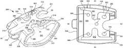
- FIG. 7is a perspective view of a surgical guide structure according to one embodiment of the present disclosure.
- FIG. 8is a bottom view of the surgical guide structure of FIG. 7 .
- FIG. 9is an end view of the surgical guide structure of FIG. 7 .
- FIG. 10is a sectional view of the surgical guide structure of FIG. 7 .
- FIG. 11is a close up top view of the surgical guide structure of FIG. 7 .
- FIG. 12illustrates an ankle joint prepared for placement of implants according to one embodiment of a method of the present disclosure.
- FIGS. 13-14illustrate a surgical guide structure positioned on the talus in further steps of the method.
- FIGS. 15A-Bdepict an alternate step to that shown in FIG. 14 where holes are drilled at an acute angle relative to the resected top surface of the talus.
- FIGS. 16-17depict removal of the surgical guide structure according to further steps of the method.
- FIG. 18depicts a step of evaluating the dimensions of a prepared tibia for determining the proper size of a tibial component according to a further step of the method.
- FIG. 19depicts placement of a barrel hole plate onto the tibia according to a further step of the method.
- FIGS. 20-22depict placement of a trial implant on the prepared talar surface according to further steps of the method.
- FIG. 23illustrates a talar implant in phantom and positioned on a prepared talar surface.
- FIG. 24illustrates a sectional view of the talar implant of FIG. 23 .
- FIG. 25is a perspective view of a joint space evaluator according to one embodiment of the present disclosure.
- FIGS. 26-28are various views of the joint space evaluator of FIG. 25 .
- FIG. 29is a perspective view of a post talar cut template according to one embodiment of the present disclosure.
- FIG. 30is a front view of an ankle prepared for placement of the joint space evaluator according to one embodiment of a method of the present disclosure.
- FIG. 31is a top view of a template frame of the post talar cut template of FIG. 25 positioned on a resected talus according to one embodiment of a method of the present disclosure.
- FIGS. 32 and 33are top and perspective views, respectively, of a drill guide attached onto the post talar cut template according to further steps of the method.
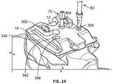
- FIG. 34is a side view of a datum pin inserted into the drill guide according to a further step of the method.
- FIG. 35is a perspective view of the post talar cut template removed from the bone surface according to a further step of the method.
- proximalmeans close to the heart and the term “distal” means more distant from the heart.
- distalmeans more distant from the heart.
- anteriormeans toward the feet and the term “superior” means toward the head.
- anteriormeans toward the front part or the face and the term “posterior” means toward the back of the body.
- medialmeans toward the midline of the body and the term “lateral” means away from the midline of the body.
- the present disclosurerelates to devices, systems, kits and methods used in joint repair surgeries.
- the embodimentsrelate to structures and associated uses of such structures in preparation for implant placement, including placement of a prosthetic implant on a resected talar surface in the foot.
- the embodimentsare described with particular application to the ankle joint, it is contemplated that the teachings embodied by the described structures and methods may be incorporated into devices, systems, kits and methods used in other areas of the body.
- the teachings of the present disclosuremay be used to improve upon hip, knee, elbow, shoulder and smaller joint (such as wrist, finger, or toe) replacement surgeries.
- the present disclosurerelates to a trial talar implant, or trial implant, with openings.
- the openingsfunction as windows through the trial implant structure so that surfaces under the trial implant are visible through the openings.
- the trial implantis suited for the measurement of talar resections, i.e., cuts, and is shaped accordingly. Such measurement aids in determining whether the resections are satisfactory or whether further cutting of the talus is necessary.
- FIGS. 1-4One embodiment of a trial implant is shown in FIGS. 1-4 .
- Trial implant 100includes a central portion 110 and outer portions 120 , 130 .
- Central portion 110includes a top face 111 , which in this embodiment defines top surfaces 112 , 114 separated by a ridge 113 .
- Each top surface 112 , 114is convex in shape and extends between first and second ends 101 , 102 of the trial implant.
- Trial implant 100is sized to correspond to a talar implant size.
- convex top surfaces 112 , 114have a radius and other surface features dimensioned to predict how well the actual permanent (long-term) prosthetic implant, when secured to the talus, will be able to articulate and otherwise function within the joint.
- upper surfacesrepresent an articulating surface.
- This articulating surfaceis shaped to be the same as an articulating surface for a permanent implant of the same size.
- Top surfaces 112 , 114are generally unobstructed although an opening 144 exists near first end 101 , as shown in FIGS. 1 and 2 .
- Bottom surface 150 of trial implant 100is generally planar as shown in FIG. 4 while bottom surfaces 152 , 154 taper toward first and second ends 101 , 102 , such as is shown in FIG. 4 .
- Bottom surfaces 150 , 152 , 154are shaped to correspond to resected surfaces 12 , 18 , 19 , as shown in FIGS. 12 and 17 .
- trial implant 100When trial implant 100 is positioned on surfaces 12 , 18 , 19 , ends 101 and 102 will contact or otherwise be adjacent to surfaces 19 and 18 , respectively, as shown in FIG. 21 .
- Extending from a central location on bottom surface 150is a protrusion in the form of a post 156 .
- the postis configured for placement in a hole through the top resected surface of the talus to secure trial implant 100 to bone.
- an inner surface of outer portion 120corresponds to bone surface 14 while an inner surface of outer portion 130 corresponds to bone surface 16 .
- Bridging a separation between top surfaces 112 , 114 and bottom surfaces 150 , 152 , 154are side surfaces 118 , 119 . Both side surfaces 118 , 119 have angled surfaces moving inward from top surfaces 112 , 114 toward bottom surfaces 150 , 152 , 154 . As best shown in FIG. 3 , an angle of surface 118 is shallower than an angle of surface 119 when the angle is measured relative to an axis through post 156 . In this manner, surface 118 is closer to being perpendicular to bottom surface 150 when compared to surface 119 . Each of side surfaces 118 , 119 has a depth and angle to correspond and otherwise mimic an implant size.
- trial implant 100is configured so that when it is positioned on a bone, e.g., a talus, it provides visual cues as to whether the implant would impinge on adjacent bodily structures or other implant components on the medial or lateral side of the implant. Due to the angle of side surfaces 118 , 119 , a combined width of top surfaces 112 , 114 is greater than a width of bottom surface 150 . Also, each side surface 118 , 119 has a lesser dimension extending between bottom and top surfaces than the width of either top 112 , 114 or bottom 150 surfaces.
- the unique geometry defined in part by side surfaces 118 , 119provides a large area articulation surface on the top of the trial while at the same time also leaves space for openings 140 , 142 sufficiently sized so that multiple resected bone surfaces may be viewed through such openings when trial implant 100 is seated on a bone.
- opening 144extends through top surfaces 112 , 114 adjacent to first end 101 , as shown in FIG. 1 .
- opening 144allows for visualization of resected anterior surface 19 , as shown in FIG. 21 .
- Trial implant 100also includes a bar 116 extending across first end 101 between outer portions 120 , 130 . Opening 144 is defined on one side by bar 116 and on others by top surfaces 112 , 114 , as shown in FIG. 1 .
- Within opening 144is a surface 160 , as best shown in FIG. 1 .
- Surface 160includes openings 162 , 164 , which are configured to allow engagement by a tool such as a forceps or for evaluating a position of trial implant 100 relative to the surrounding anatomy.
- Trial implant 100also includes outer portions 120 , 130 .
- Outer portion 120 and outer portion 130are different from one another.
- Outer portion 120is a curved shape as shown in FIGS. 1, 3 and 4 , and extends from first end 101 to second end 102 .
- Outer portion 120includes lateral branches 124 , 126 connecting a longitudinal segment of outer portion 120 with central portion 110 . Positioning of lateral branches 124 , 126 is such that outer portion 120 lies entirely on one side of a plane through side surface 118 .
- the curve of the longitudinal segment of outer portion 120is outward relative to side surface 118 and bottom surface 150 so that an apex 122 of outer portion 120 roughly represents a location of maximum width of opening 140 , as best shown in FIGS. 1 and 4 .
- outer portion 120is monolithic with central portion 110 and extends from ends 101 and 102 of central portion 110 .
- a space between side surface 118 and outer portion 120defines opening 140 .
- Opening 140extends between ends 101 and 102 .
- opening 140widens from end 101 toward apex 122 then narrows from apex 122 toward end 102 .
- Outer portion 130extends from first end 101 to second end 102 and includes lateral branches that connect a longitudinal segment with central portion 110 .
- an outer edge 132 of outer portion 130is curved, as shown in FIG. 2
- a longitudinal axis through the longitudinal segment of outer portion 130is generally linear and of a constant depth relative to bottom surface 150 , unlike the longitudinal segment of outer surface 130 .
- the constant depth of outer portion 130is visible in FIGS. 3-4 , for example.
- Opening 142is smaller than opening 140 and is generally uniform in width between ends 101 and 102 , as can be seen from FIGS. 2 and 22 .
- one functional difference between opening 140 and 142 when trial implant 100 is secured on talus 10is that a larger area of resected surface 14 is visible through opening 140 when compared with an area of resected surface 16 visible through opening 142 .
- a trial implant designed for implantation in the joint of a patient with a small talusis contemplated, as shown in FIGS. 5 and 6 .
- top surfaces 212 , 214are equivalent to top surfaces 112 , 114 and have the same diameter.
- One difference between trial implant 100 and trial implant 200is that a depth of trial implant 200 is less than that of trial implant 100 .
- bottom portions including the bar and portions of outer portionsare removed, while maintaining the bearing surfaces needed on the top of the trial. For example, as visible in FIG.
- trial implant 200does not include a bar at its first end 201 , unlike trial implant 100 .
- Trial implant 200includes a central portion 210 and outer portions 220 , 230 , as in the embodiment of FIG. 1 . Also similar are openings 240 , 242 between outer portion 220 and central body portion 210 and between outer portion 230 and central body portion 210 , respectively.
- a recessed area defined by walls 260 , 264 , 266replaces a closed opening through the top surfaces.
- each opening/windowmay vary from that shown in the depicted embodiments.
- the size of each windowmay be larger or smaller than that depicted.
- the windowmay be sized and positioned so that one, two, three, or four resected surfaces are visible when the trial is positioned on a resected talus.
- the number of windowsmay also be varied.
- a trial implantmay include one, two, three, four, or more windows.
- a windowmay be included on the posterior side through the convex surface of the trial.
- sloped side surfaces between the top surface and the bottom surface of the trial implantmay vary from those shown in the depicted embodiment.
- An angle of either or bothmay be less or greater than that shown, and may vary in unison or independently.
- a length of either side surfacemay also vary.
- Protrusions, or spikesmay be absent from the bottom surface of the trial or may be included in a quantity of one or more.
- a shape of each protrusionmay vary from that shown in the depicted embodiment and where two or more protrusions extend from the bottom surface, each protrusion may have a shape independent of the other.
- various securement mechanismsas known in the art, other than the aforementioned spike or protrusion, may be used to releasably secure the trial implant to bone when in position for implant placement preparation.
- a geometric shape of the bottom surface of the trial implantmay be altered from the shape defined by bottom surfaces 150 , 152 , 154 of the embodiment depicted in FIGS. 1-4 . In this manner, there may be four or more bottom surfaces.
- the outer portions of the trialmay also have geometry that varies from the depicted embodiments.
- a singular outer portionmay define a perimeter of the trial implant, extending around the central portion and separated from it by openings.
- the trial implantincludes two outer portions that may both be curved or parallel to a bottom surface of the trial. Where an outer portion is curved, the radius may vary or be constant, and may be any radius feasible within an available space. Each outer portion may be varied with respect to the other. A cross sectional shape of the outer portions may also vary based on considerations such as space needed for use and material choice, among other factors.
- the trial implantincludes a single outer portion. In any of the above embodiments and examples, the structure of the trial implant may be monolithic or modular.
- the trial implantmay also be shaped for seating on resected bone surfaces in other joints.
- the trial implantmay include windows and/or recesses so that two, three, four, five, or more resected surfaces are visible.
- stainless steelmay be used to manufacture the trial.
- manufacture of the trialmay be accomplished using machining techniques. Other materials and manufacturing techniques one of ordinary skill would consider using for trial implants are also contemplated.
- the trialmay be manufactured in known ways and shipped to operators for use in a patient.
- the trialmay be formed as a custom trial implant at the surgical facility using an Additive Layer Manufacturing (ALM) fabrication process such as selective laser sintering (SLS), selective laser melting (SLM), or electron beam melting (EBM), as disclosed in U.S. Pat. Nos. 7,537,664; 8,728,387; 9,180,010; and 9,456,901, the disclosures of which are hereby incorporated by reference in their entireties herein.
- ALMAdditive Layer Manufacturing
- SLMselective laser melting
- EBMelectron beam melting
- Other appropriate 3D printing technologies known to those skilled in the art, such as fused deposition modeling,may also be used.
- articlesare produced in layer-wise fashion according to a predetermined digital model of such articles by heating, e.g., using a laser or an electron beam, multiple layers of powder, which preferably may be a metallic powder, that are dispensed one layer at a time.
- the powderis sintered in the case of SLS technology and melted in the case of SLM technology, by the application of laser energy that is directed in raster-scan fashion to portions of the powder layer corresponding to a cross section of the article.
- an additional layer of powderis dispensed, and the process repeated, with sintering or melting taking place between the current layer and the previously laid layers until the article is complete.
- the powder layerssimilarly may be heated with EBM technology.
- Additive manufacturing techniquessuch as the ALM processes described above may be employed to form the trial implant and any other components, as applicable.
- materials for one layermay be different than the materials for successive layers.
- the above described custom trial implantcan be formed based on data of the particular surgical site, such as the shape of the prepared talus bone.
- Surgical guide structure 300includes a main body with a principal top surface 310 having forked extensions 312 , 314 defining a gap therebetween at a first end 301 and a central extension 316 at a second end 302 .
- Central extension 316protrudes from outer portions 318 , 320 and includes medial and lateral concave surfaces 317 .
- top surface 310has a neck 315 as shown in FIGS. 7 and 8 .
- An axis 50extends longitudinally between first and second ends 301 , 302 dividing structure 300 into approximately equal sections, as best shown in FIG. 8 .
- One sectionincludes an entirety of outer portion 320 while the other includes an entirety of outer portion 330 .
- Passing through top surfaceare five apertures 362 , 364 , 366 , 368 and 370 .
- Apertures 362 , 364are defined by varying angle perimeter walls, described in greater detail below, while apertures 366 , 368 define a cylindrical path through the surgical guide structure.
- Aperture 370is centrally located on the guide structure on axis 50 and is adjacent to neck 315 of top surface 310 , as shown in FIGS. 7 and 8 .
- these sections of the surgical guide structureare nearly but not quite symmetrical.
- the section having outer portion 320tapers outward from first end 301 toward second end 302 so that it is much wider at end 302 .
- outer portion 320itself is of a different shape than outer portion 330 .
- Outer portions 320 , 330are on lateral sides of surgical guide structure 300 and extend generally along a length of the body. Outer portion 320 is curved in a concave manner relative to both surface 310 and side surfaces 382 , 386 such that an approximate midway point of outer portion 320 is furthest from top surface 310 compared to other locations on outer portion 320 . This curve is seen from different perspectives in FIGS. 7-10 .
- Surfaces 380 , 382 , 384 , 386 of the guide structuredefine an opening 340 , as best shown in FIG. 7 .
- Surface 384is an inner edge part of outer portion 320 while the remaining surfaces define an edge of the main body of structure 300 .
- surface 382tapers away from axis 50 toward second end 302 and is generally linear. Approximately midway between first and second ends 301 , 302 , surface 382 transitions to U-shaped surface 380 , which extends inward toward axis 50 and includes a radius centered on axis 60 , as shown in FIGS. 7 and 8 . U-shaped surface is sized and positioned so that it lies in between apertures 364 and 368 . Continuing toward second end 302 , surface 380 transitions to surface 386 , which is on approximately the same plane as surface 382 , as best shown in FIG. 8 . In this manner, surface 386 tapers away from axis 50 toward second end 302 .
- Connecting surfaces 382 and 386is surface 384 on a side of outer portion 320 .
- Surface 384has a large radius, also shown in FIG. 8 , and tapers away from axis 50 from first end 301 to second end 302 .
- Opening 340is defined by surfaces 380 , 382 , 384 , 386 , which form a perimeter around opening 340 .
- outer portion 330On an opposite side of axis 50 lies outer portion 330 separated from the main body of structure 300 by opening 342 .
- outer portion 330is of a generally linear shape and does not curve out of a plane parallel to top surface. This difference between outer portions 320 , 330 is best shown in FIG. 9 .
- surfaces of structure 300 that define opening 342are generally parallel to axis 50 , as best shown in FIG. 8 .
- a U-shaped surfaceextends inward toward axis 50 opposite surface 380 near the midway location on the length of surgical guide structure 300 , defining a portion of neck 315 on surface 310 .
- a central bottom surface 350 of surgical guide structure 300is planar and parallel to top surface 310 .
- Apertures 362 , 364 , 366 , 368 , 370extend between top surface 310 and bottom surface 350 .
- Adjacent to first end 301are bottom surfaces 354 A-B, which taper away from the plane through top surface 310 .
- bottom surface 352tapers away from the plane through top surface 310 .
- An angle of each surface relative to bottom surface 350is best shown in FIG. 10 .
- apertures 366 and 368are cylindrical, as shown in the section view of FIG. 10 , and extend in a direction orthogonal to top surface 310 .
- Aperture 370is similar to apertures 366 , 368 . However, among each other, apertures 366 , 368 , and 370 may vary in shape and size. For example, aperture 370 , serving a different purpose than apertures 366 , 368 , may be of a different size.
- apertures 362 , 364are defined by walls at varying angles relative to top surface 310 of the guide structure.
- walls 363 Cthat are orthogonal to top surface 310
- walls 363 A-Btaper outward from the bottom surface of guide structure 300 toward the top surface such that the aperture has a larger cross-sectional area at the top surface.
- FIGS. 10 and 11show how the taper of aperture 362 is staggered and in this manner, there is a first tapered wall 363 A from the bottom surface and then a second tapered wall 363 B, separated from the first by a step 369 .
- the stepis shown in FIG. 10 and the U-shape of the step is shown in FIGS. 11 and 13 .
- the shape and size of the stepmay vary from that shown.
- tapered portions of the wallmay be continuous through a depth of the guide structure without any steps.
- the sloping surface of walls 363 A-Btransitions to the right angle walls 363 C on the lateral sides of aperture 362 , as shown in FIG. 11 .
- Guidance for drilling holes perpendicular to top surface 310 of guide structure 300is provided by right angle walls 363 C during the drilling procedure.
- the tapered wall surfacedefines a transverse direction for a path of the aperture through the surgical guide structure.
- apertures 362 , 364are transverse relative to apertures 366 , 368 .
- apertures 362 , 366are nearly symmetrical to apertures 364 , 368 about axis 50 .
- apertures 362 , 364accommodates placement of a drill bit therein either at a right angle or an acute angle relative to a surface of the guide structure.
- a slope of walls 363 A-B for aperture 362 and corresponding walls for aperture 364provides for an acute angle approach from an anterior direction.
- the inclusion of apertures 362 , 364 as described hereinincreases the options available to a surgeon for accessing the guide structure when the guide structure is positioned on a talar bone to create holes in the talus. If it is not possible to drill perpendicular to the top bone surface, drilling may be at an acute angle, as shown in FIGS. 15A, 15B , and described in greater detail as part of the method embodiments herein.
- the shape and the size of the aperturesmay be varied to accommodate hole formation instruments other than drill bits.
- any of the embodiments of the disclosure referencing apertures sized for a drill bitis contemplated as having apertures that may vary to accommodate hole formation instruments other than drill bits.
- the surgical guide structuremay be varied in many ways.
- the surgical guide structuremay be varied in ways similar to those described for the trial implant above.
- the openings, i.e., windows, between the main body and the outer portionsmay also vary in shape and size to suit intended applications.
- the opening sizesmay vary in tandem relative to the above described embodiment, or the opening on one side may vary in size and shape relative to the other opening.
- the number, size, and/or location of the aperturesmay be varied to accommodate the type of implant intended for placement.
- the apertures with tapered wallsmay include walls having any variation of taper along a wall depth relative to the top surface of the guide structure. A maximum angle of the taper may also vary to accommodate alternative uses.
- the posterior aperturesmay have tapered walls with a maximum angle of 20 degrees relative to an axis orthogonal to the top surface of the guide structure.
- the tapered portionmay have no step or where there is a step, its width and depth relative to the top surface of the guide structure may vary.
- the characteristics of the aperturesmay be such that each is unique and independent of the others or so that groups of apertures share physical characteristics.
- the neck region near the mid point of the guide structure lengthmay be narrower or wider than that of the above embodiment.
- the fork shaped extensions and central extensionmay also vary in size and dimension.
- the overall shape of the main body of the surgical guide structuremay vary to suit an applicable bone geometry, for example. Similar principles apply to dimensions of the outer portions. For example, the depicted radius of the curved outer portion may vary from that shown in FIG. 7 . In other examples, the shape of the surgical guide structure may also be varied for applications in joints other than the ankle.
- the trial implantmay also be shaped for seating on resected bone surfaces in other joints. In such cases, the trial implant may include windows and/or recesses so that two, three, four, five, or more resected surfaces are visible.
- Manufacture of the surgical guide structuremay be through known procedures or, alternatively, a custom surgical guide structure may be formed through ALM fabrication processes, such as those described above for the trial implant.
- a systemin another aspect, includes surgical guide structure 300 as shown in FIG. 7 and a talar implant 400 , as shown in FIG. 23 .
- surgical guide structure 300is sized, shaped and includes apertures therethrough such that when it is positioned on resected surfaces of a talar bone, holes in the talar bone may be drilled in an accurate manner for the placement of talar implant 400 .
- apertures 362 , 364 , 366 , 368 and 370e.g., FIG.
- surgical guide structure 300relates to talar implant 400 .
- a section view of talar implant 400reveals spike protrusions 462 , 464 , 466 , 468 , 469 that are orthogonal to a bottom surface 412 of the implant, and an orientation of such spikes relative to holes 62 , 64 , 66 , 68 , 69 in bone 10 .
- holes 62 , 64 , 66 , 68 , 69are the product of drilling via surgical guide structure 300 . It can be seen in FIG. 24 that spikes from implant 400 may be positioned in a respective hole of bone 10 even when the hole is drilled at an acute angle. In particular, spike protrusions 462 , 464 are at an angle relative to holes 62 , 64 . Implant 400 also includes a convex top surface 410 shaped to form an articulation surface, such as with a bearing placed between the tibial component and the talar component.
- the systemmay be varied to include any combination of devices as contemplated in this disclosure. For example, another system may include a trial implant and a permanent implant.
- kitsare contained in a single package as a system or in multiple packages that may be selected as needed by the operator to form a system.
- a kitmay include a trial implant, a talar implant and a surgical guide structure. If the kit includes more than one trial implant, surgical guide structure and/or talar implant, the plurality of trial implants, surgical guide structures and/or talar implants may vary in overall size, opening sizes, aperture sizes, as applicable, materials, or the like, from which the most suitable elements may be chosen for a particular surgical procedure.
- the kitmay include one or more of a trial implant, a talar implant and/or a surgical guide structure. Any combination of trial implants, implants, tools, instruments and other devices may also be included in a single package or in separate packaging which are later brought together as a kit.
- kitmay be varied in many ways.
- any combination of the devices described hereinmay be included as part of a kit.
- Thismay be in the form of a kit of the above embodiments combined with one or more of a trial bearing, a ruler, a joint space evaluator, a barrel hole plate, a thread pin, a forceps and/or a drill.
- Such elementsmay be included as single elements or more than one may be included.
- tools or devicesmay also be included in the kit.
- the various combinations of elements of any contemplated kitmay be included in a single package or distributed among multiple packages.
- the kits contemplated hereinmay be accompanied by an instruction manual on how to perform one or more of the methods of using the contents of the kit.
- surgical guide structure 300is used to prepare pilot holes, also referred to as holes, in a resected talar bone surface as part of an ankle replacement procedure.
- the talar boneis resected by any method known in the art, such as those described in U.S. Pat. Pub. No. 2012/0130376, hereby incorporated by reference herein in its entirety.
- the purpose of the holesis to facilitate placement of a trial implant, such as trial talar implant 100 , or a permanent implant, such as talar implant 400 .
- the method of preparing the talar bone for drilling of holesbegins with placement of surgical guide structure 300 onto a talar bone surface.
- surgical guide structure 300is placed onto talar bone 10 shown in FIG. 12 .
- Talar bone 10is prepared through resection of several surfaces as depicted in FIGS. 12 and 17 including top surface 12 , anterior surface 19 , posterior surface 18 , lateral surface 14 and medial surface 16 .
- the footis depicted in FIG. 12 as having a particular orientation relative to tibia 20 , such orientation is merely exemplary and performance of the methods as described herein do not require the particular orientation of the foot relative to the tibia as illustrated.
- surgical guide structure 300is held and transported into position on talar bone 10 , fitting onto the resected surfaces as described above and as shown in FIG. 13 .
- bottom surface 350( FIG. 8 ) corresponds to top resected surface 12
- surface 352corresponds to anterior resected surface 19
- surfaces 354 A-Bcorrespond to posterior resected surface 18 .
- the location of the resected surfaces relative to the surgical guide structure positioned on the boneis evident with a view to FIG. 13 .
- the resected surfacesare shown in isolation in FIG. 17 .
- Surgical guide structureis shaped and includes openings so that multiple resected surfaces remain visible when surgical guide structure is positioned on the talus.
- opening 340 of surgical guide structure 300permits the viewing of both top and lateral resected surfaces, 12 and 14 respectively, while opening 342 permits the viewing of both top and medial resected surfaces 12 and 16 , respectively, as best shown in FIG. 14 .
- opening 340 of surgical guide structure 300permits the viewing of both top and lateral resected surfaces, 12 and 14 respectively
- opening 342permits the viewing of both top and medial resected surfaces 12 and 16 , respectively, as best shown in FIG. 14 .
- a pin 70is inserted through central aperture 370 of the surgical guide structure, as shown in FIG. 13 .
- the pin 70may be threaded and is inserted into aperture 370 by hand without tools so that pin 70 is not over inserted.
- a toolmay be used to insert pin 70 , although in such cases, a final stage of advancement will be performed manually to ensure that pin 70 is not over inserted.
- holesare drilled in preparation for trial and implant placement.
- a drill 80is used, the drill shown being inserted into aperture 368 in FIG. 14 . Holes are created by drilling through each of apertures 362 , 364 , 366 and 368 . Relative to the anatomy of the patient, apertures 362 , 364 are posterior and apertures 366 , 368 are anterior. Each hole is made at a ninety degree angle relative to top surface 12 of talus 10 .
- drill 80will have created four holes, as shown with guide structure 300 removed in FIG. 17 .
- FIGS. 15A-Billustrates the creation of a hole at an angle through aperture 362 .
- Drill 80is inserted on an anterior side of aperture 362 in a manner so that it is aligned with walls 363 A-B. In this manner, walls 363 A-B function as a guide for drill 80 .
- drill 80is advanced until a shoulder on drill 80 is obstructed by the step between walls 363 A and 363 B, as best shown in FIG. 15B .
- the hole created through such drillingmay be at any angle relative to an axis perpendicular to the top surface of the guide structure, for example, up to 35 degrees. In this manner, the drill bit trajectory may be at 10 degrees, 20 degrees, and so on.
- FIG. 16depicts the guide structure with the pin removed.
- guide structure 300may be held down on the bone while threaded pin 70 is removed.
- drill 80is used to drill a fifth hole 69 in talus 10 central to the other four 62 , 64 , 66 , 68 .
- the appearance of talus 10 following creation of all five holesis shown in FIG. 17 .
- an implantcan be seated onto the prepared talar bone, or alternatively, a trial implant may be seated on the prepared bone to ensure that a permanent implant will seat properly and be properly aligned with the tibial bone and/or another implant component.
- a trial implantis used to ensure a permanent implant will seat correctly on top of the talus and to verify that a range of motion for the permanent implant, e.g., implant 400 , will be sufficient relative to the tibia and/or another implant component.
- talar bone 10includes several resected surfaces so that it is ready for placement of trial implant 100 thereon.
- talar bone 10may include resected surfaces 12 , 14 , 16 , 18 and 19 as shown in FIG. 17 . Each resected surface abuts at least one other resected surface in the illustrated preparation. For example, top surface 12 abuts anterior surface 19 .
- a toolsuch as a forceps (not shown) is used to place trial implant 100 on the talar bone.
- protrusion 156is positioned over hole 69 , as best shown in FIG. 20 .
- FIGS. 21 and 22illustrate how trial implant 100 appears when completely advanced onto talar bone 10 . If trial implant 100 is properly seated on the talus, top resected surface 12 will be flush with lower surface 150 of trial implant 100 . To verify that the trial implant is fully seated on the talus, windows 140 , 142 , 144 allow for viewing of the talar surface while the trial implant is in place on talus 10 .
- FIG. 21Seating of trial implant 100 on lateral resected surface 14 is viewed from opening 140 , as shown in FIG. 21 .
- Seating on anterior resected surface 19is viewed through opening 144 as also shown in FIG. 21 .
- Seating on medial resected surface 16is viewed through opening 142 , as shown in FIG. 22 .
- FIG. 21several resected surfaces are visible when trial implant 100 is seated on bone 10 . These include top surface 12 , medial surface 14 , and anterior and posterior surfaces 19 and 18 . This is made possible in part by lateral branches 124 , 126 of the outer portions extending from the main body, which provides space between the top resected surface and the side surface 118 .
- the methodalso includes verification of the range of motion for the final implant using the trial implant.
- a barrel hole platee.g., barrel hole plate 40 in FIG. 19
- additional proceduresmay be performed to prepare the tibia prior to placement of the barrel hole plate, such as verification of the tibial implant size and using the barrel hole plate to drill holes in the tibia in preparation for tibial implant placement.
- a trial bearing(not shown) is inserted in between trial implant 100 and barrel hole plate 40 in the ankle joint space.
- the trial bearingis replaced with a trial bearing of a larger size.
- ankle stabilityis assessed by rotating the foot of the patient about the ankle.
- the size of the trial bearingmay also be reassessed.
- the spacing between eachis evaluated to determine whether there is a gap on only one side of the trial bearing between the bearing and one of the tibial and talar implants. If so, ligament release may be performed to balance the ankle joint. Following ligament release, a larger trial bearing is used to reassess whether the proper bearing size has been identified.
- a surgical methodincludes using surgical guide structure 300 as described above (see FIGS. 12-17 ) to prepare holes in a resected talar bone surface for the placement of a trial implant or a talar implant in a talar bone.
- the methodalso includes placing trial implant 100 onto the prepared talar surface to make sure the implant will seat correctly on top of the talus and to verify that a range of motion for the final implant will be suitable, as described above (see FIGS. 20-22 ).
- the methodincludes additional steps between using surgical guide structure 300 to create holes in the resected talar bone surface and placement of trial implant 100 .
- the talar boneappears as shown in FIG. 17 .
- a size of a tibial implant componentis determined.
- a ruler 30is placed underneath a previously resected underside surface 22 of tibia 20 , as shown in FIG. 18 .
- ruler 30is advanced to the posterior edge of the resected surface.
- an anterior/posterior dimension of the tibiais obtained. As needed, this dimension may be measured at one or more locations between the medial and lateral sides of the tibia.
- a tibial componentis then selected that corresponds to the measured dimension.
- an appropriate barrel hole plate 40is selected and then inserted over resected surface 22 of tibia 20 , as shown in FIG. 19 .
- space in between the plate and the resected talar surfaceis evaluated to determine whether it is adequate for the implants to be used in the ankle replacement.
- Etching 44 on a bottom surface of barrel hole plate 40mimics a physical location of a bottom surface of the tibial implant to assist with the determination.
- the methodmay be complemented with fluoroscopy to provide additional information regarding positioning of the barrel hole plate.
- a surgical methodincludes placing trial implant 100 onto a prepared talar surface to make sure the implant will seat correctly on top of the talus and to verify that a range of motion for the final implant will be suitable, as described above (see FIGS. 20-22 ).
- a talar implant 400is retrieved.
- a toolsuch as a forceps (not shown), is used to grasp talar implant 400 and place it onto talus 10 .
- talar implant 400may first be attached to a talar implant holder, and the forceps may grasp the talar implant holder and then guide the talar implant into place on the talus.
- protrusion 469 of talar implant 400 shown in FIGS. 23 and 24such protrusion 469 is aligned and otherwise positioned over hole 69 and then advanced into hole 69 , hole 69 being through top resected surface 12 of talus 10 .
- protrusions 462 , 464 , 466 , 468are aligned with respective holes 62 , 64 , 66 , 68 in the talus to position and secure talar implant to the talus, as shown in FIG. 24 .
- protrusions 462 , 464When one or more of holes 62 , 64 have been drilled at an angle, protrusions 462 , 464 enter holes 62 , 64 and at least a portion of such protrusions enter the bone adjacent to the bone hole. In this manner, a portion of protrusions 462 , 464 is in the hole while another portion is in the bone.
- a mallet or other toolmay be used to apply an impaction force onto the implant.
- surface 412 of talar implant 400When fully seated, surface 412 of talar implant 400 is flush with top resected surface 12 , as shown in FIG. 24 .
- a joint space evaluator(not shown) may be inserted into the ankle joint space to verify that the talar implant is fully seated.
- fluoroscopymay be used to confirm that the talar implant is properly seated in one or more of the anterior/posterior directions and medial/lateral directions.
- the immediately preceding embodimentalso includes additional preparation after evaluation of the talar resections with the trial implant and drilling of holes in the talus (as shown in FIGS. 20-22 ).
- preparation of the tibia for implant placementA poly trial or a tibial barrel hole wedge may be used to verify that a prepared, e.g., resected, tibial surface facing the ankle joint is finished to be flush with a barrel hole plate to be placed thereon. Such verification allows for improved positioning of the barrel hole plate on the prepared tibial surface adjacent the trial implant.
- the barrel hole plateis secured to the tibia with fixation pins. Holes are then drilled in the tibia, one at a time, through openings in the barrel hole plate to allow for insertion of the tibial implant.
- Other stepsmay include assessment of a size of the bearing for the joint.
- a trial bearingis placed into the joint space between the trial implant and a plate of the barrel hole plate.
- the ankleis then rotated to evaluate the implant sizes and also to assess ankle stability. If a gap of more than 1 mm is observed between the bearing and the adjacent components, the trial bearing should be substituted with a bearing one size larger and the same assessment should be performed again. Any variation in a gap between the bearing and the adjacent barrel hole plate or trial implant from one side to the other in a lateral direction suggests that ligament balancing may be necessary.
- the trial and the barrel hole plateare removed. Once the site is cleared as needed, talar implant 400 is placed into position on the talus, as described above.
- a surgical methodincludes using surgical guide structure 300 as described above (see FIGS. 12-17 ) to prepare holes in a resected talar bone surface for the placement of a trial implant and a talar implant therein. It also includes placing trial implant 100 onto the prepared talar surface to ensure the implant will seat correctly on top of the talus and to verify that a range of motion for the final implant will be suitable, as described above (see FIGS. 20-22 ). Finally, the method concludes with the placement of a talar implant, as described above, where the seated implant is as shown in section in FIG. 24 . This method may be varied in many ways. For example, the method may also include any number of additional steps as described in the various aforementioned embodiments.
- a method of placing prostheses in the ankleincludes preparation of anatomy around and within an ankle joint followed by placement of a talar implant.
- a tibial alignment guide(not shown) is set up and otherwise positioned on the tibia.
- a pin block(not shown) is then locked into position on the alignment guide with adjustments made as necessary.
- Further alignment of the tibial alignment guidemay also be performed prior to tightening to fix the tibial alignment guide in place.
- the guideis then aligned with the coronal and sagittal plane through further adjustment of the tibial alignment guide and through attachment of a parallel alignment guide (not shown) to the tibial alignment guide. Once alignment is complete, the parallel alignment guide is removed.
- a tibial cut guide(not shown) is attached to the pin block. To limit the amount of bone that can be resected, adjustments are made using the pin block. Fluoroscopy may be performed at this juncture to check the alignment of the cut guide and other instrumentation. Further adjustments may then be made, as needed. Pins are used to lock the amount of tibial resection and the instrumentation is ready for use. An oscillating saw is advanced into a slot of the cut guide to make a transverse distal tibial cut within the tibial cut guide while a reciprocating saw is used to make a cut along the inner edge of the medial malleolus. The tibial cut guide is then removed and the resected bone is removed.
- the talar boneis prepared for resection.
- a talar cut guide(not shown) is placed on the tibial alignment guide and pins are inserted into the guide as needed.
- An oscillating sawis used to make an initial transverse distal talar cut.
- a joint space between the talus and tibiais evaluated.
- a templateis used to determine a necessary size of the talar implant.
- a drill guideis attached to the template and a pin is inserted through the drill guide. With the pin in place over the talus, the pin is used to guide a datum into position on the talus. Once the datum is secured, a talar anterior/posterior cut guide is secured to the datum.
- the anterior/posterior cut guideis then removed and a talar medial/lateral cut guide is attached to the datum. Medial and lateral cuts are then made, and the medial/lateral cut guide is removed. Upon completion, the talus will have at least top, posterior, medial and lateral resected surfaces.
- One example of the performance of these stepsis provided in U.S. Pat. Pub. No. 2012/0130376.
- surgical guide structure 300is used to create holes in the top resected surface of talus 10 . This is followed by evaluation of sizing and positioning for the talar implant using trial implant 100 .
- talar implant 400is placed on talus 10 . Each of the aforementioned steps may be performed as described above. To complete the surgery, steps as known to those of skill in the art are taken to implant the tibial implant. This represents the end of the procedure and is followed by closure of the incision in the patient.
- a joint space evaluator 500is as shown in FIG. 25 .
- Joint space evaluator 500includes a main body 510 and a pivoting member 520 and has a length that extends from a first end 502 to a second end 504 .
- Main body 510 of joint space evaluator 500has a linear shape ( FIG. 26 ) and includes a series of finger grips 512 toward first end 502 and a recessed portion 513 toward second end 104 .
- Recessed portion 513is shaped to accommodate placement of pivoting member 520 thereon, as shown in FIG. 25 , for example.
- recessed portion 513includes sloped side surfaces 515 A-B separated by a convex surface 516 , shown in section in FIG. 28 . These surfaces extend over two separate lengthwise sections of recessed portion 513 , divided by an internal extension 526 of pivoting member 520 , as shown in FIG. 27 .
- recessed portion 513also includes an opening 518 extending therethrough and internal to main body 510 ( FIGS. 25, 28 ). Opening 518 is oriented and positioned lengthwise to be aligned with a pivot axis 550 extending along the length of joint space evaluator 500 , as shown in FIGS. 25 and 28 .
- a flat planar bottom surface 514On a surface of main body 510 opposite finger grips 512 and recessed portion 513 is a flat planar bottom surface 514 . ( FIG. 28 ).
- a fixed indicator 511At a juncture between finger grips 512 and recessed portion 513 is a fixed indicator 511 .
- Fixed indicator 511is in the form of a protrusion extending outwardly from the surface of main body 510 and extends further from the surface than any other part of main body 510 , as best shown in FIG. 27 . This aids in promoting the visibility of fixed indicator 511 from various angles.
- Pivoting member 520is shaped to nest within and engage to recessed portion 513 of main body 510 , as shown in FIG. 25 .
- pivoting member 520includes internal extension 526 sized to fit within a space in a central area of recessed portion 513 , as shown in FIG. 27 .
- Internal extension 526includes an opening 527 therethrough positioned to axially align with opening 518 of recessed portion 513 when internal extension 526 is disposed in recessed portion 513 .
- a pin 524is disposed in the respective openings 518 , 527 as best shown in FIG. 27 so that pivoting member 520 is attached to main body 510 .
- side surfaces 525 A-B and concave surface 526 of pivoting member 520face sloped side surfaces 515 A-B and convex surface 516 of recessed portion 513 , respectively, as best shown in FIG. 28 .
- Concave surface 526interacts with convex surface 516 so that pivoting member 520 is pivotable relative to recessed portion 513 , i.e., main body 510 , as indicated by arrows 560 . Because sloped side surfaces 515 A-B slope downward toward outer edges of joint space evaluator 500 , a gap exists between one or both of opposing surface pairs 515 A- 525 A and 515 B- 525 B.
- pivoting member 520This provides room for pivoting member 520 to pivot relative to a position aligned with main body 510 .
- pivoting member 520is rotatable up to five degrees relative to main body 510 in either direction (i.e., clockwise and counter-clockwise) such that a top surface 528 of pivoting member 520 can be positioned at an angle up to five degrees relative to bottom surface 514 in either direction.
- the gapi.e., the amount of room, between opposing surface pairs 515 A- 525 A and 515 B- 525 B is sufficient to accommodate this range of rotation.
- the spacerwill still function to indicate that tissue balancing is required as contact with opposing bones could still be possible (e.g., one of the opposing surface pairs 515 A- 525 A and 515 B- 525 B would be in contact, indicating to the operator that soft tissue balancing in the joint, further revision of one or more bones, or a combination of the two, may be needed).
- the joint space evaluatormay have a shape and size tailored to a particular joint, such that the gap may be larger or smaller than this example to allow more or less relative rotation in the evaluator.
- the gap between pivoting member 520 and main body 510may be any amount that is sufficient to provide a visual indication to a user that the joint space is uneven.
- Pivoting member 520 and internal extension 526are structured to pivot, or rotate, about pin 524 (pivot axis 550 passes through pin 524 ) while main body 510 remains stationary.
- Pivoting member 520also includes a movable indicator 521 positioned to abut or lie adjacent to fixed indicator 511 when pivoting member 520 is attached to main body 510 . When pivoting member 520 is in alignment with main body 510 , as shown in FIGS. 25-28 , movable indicator 521 is aligned with fixed indicator 511 .
- the joint space evaluatorincludes a movable indicator on the pivoting member with markings so that each marking, when aligned with the fixed indicator on the main body, represents an angle of a top surface of pivoting member relative to a bottom surface of the main body.
- the size, materials, and/or shape of the joint space evaluator in this alternativemay be different to accommodate markings or other indicia.
- the fixed indicator 511may be larger relative to the movable indicator 521 than those shown in the depicted embodiment, such that the larger fixed indicator 511 can accommodate the markings.
- the fixed indicatoris transparent so that indicators on a face of the movable indicator facing the fixed indicator are visible through the fixed indicator and may line up with a centerline of the fixed indicator.
- the joint space evaluatorincludes a single movable indicator in the form of a liquid with bubble in a tube, similar to that used for carpentry.
- the joint space evaluatormay be varied in many ways.
- the recessed portion of the main bodyhas a concave rotational surface and the pivoting member has a corresponding convex surface.
- Other interfacing shapesare also contemplated provided that central facing surfaces of the recessed portion and the pivoting member facilitate rotation of the pivoting member relative to the recessed portion about the pivot axis.
- the indicatorsmay have a shape other than that shown in the figures.
- the joint space evaluatormay also be modified so that the indicators are spaced apart from one another, provided that the indicators are aligned with each other when the pivoting member is level with the main body.
- the overall cross-section of the joint space evaluatormay vary in shape to suit an expected space between resected surfaces or for other reasons associated with an applicable surgery.
- at least a portion of the top surface of the pivoting member and the bottom surface of the recessed portion of the main body that is placed between bone surfacesis planar.
- an overall size of the joint space evaluatormay vary to accommodate varying patient sizes.
- elements other than a pin that allow for rotation of one member relative to anothermay also be positioned in the joint space evaluator to connect the pivoting member with the main body, such as, for example, a groove and pin arrangement or the like.
- the pivoting membermay be biased in a certain direction which may provide ease of use in certain techniques.
- Post talar cut template 600includes a template frame 610 , a shaft 640 extending from frame 610 , and a handle 660 , the handle extending from an end of the shaft opposite the template frame.
- Template frame 610forms an enclosed perimeter with a template window 612 , or opening, therein, as shown in FIG. 29 .
- template frame 610has first and second inner segments 624 A, 624 B extending from shaft 640 , each of the segments extending in opposite directions from shaft 640 .
- Disposed on first inner segment 624 Aare pins 632 A-B and disposed on second inner segment 624 B are pins 634 A-B.
- Pins 632 A, 634 Aextend in a perpendicular direction away from a bottom surface of template frame 610 while pins 632 B, 634 B extend from a top surface of template frame 610 .
- Pins 632 A, 634 Aare offset relative to pins 632 B, 634 B.
- pins on both sidesmay be in line with each other.
- the pinsextend only from the bottom surface of the template frame. The pins engage with the talar bone to prevent slippage of the template from the talar surface while frame 610 is disposed thereon.
- inclusion of the pins on both the top surface and the bottom surfaceprovides a user with a choice of one side or the other for placement of the template onto a resected bone surface.
- the pins on one sideare offset relative to the pins on the opposite side, a user may have additional placement choices.
- Choicesmay be based on whether the template is used on the left or right talar bone, the overall size of the resected bone surface, or on other factors related to a particular surgery.
- a template framemay be designed to be reversible such that it can be used, on one side, for one of the right or left talar bones, and on the other side, for the other talar bone.
- the pinsmay be inline or offset, as discussed above.
- first and second lateral segments 626 , 628each of which extend in a direction away from handle 660 .
- first and second lateral segments 626 , 628extend away from the handle in parallel.
- first and second lateral segmentsare non-parallel.
- outer segment 622At an end of first and second lateral segments 626 , 628 opposite the inner segments each lateral segment 626 , 628 is interconnected by outer segment 622 .
- an inner edge of each of inner, outer and lateral segments 622 , 624 A-B, 626 , and 628define an outer dimension of window 612 .
- template window 612is a four sided polygon with lateral segment 628 having an inner edge tapering toward a central axis 1050 of shaft 640 in a direction away from shaft 640 .
- an area within an outer perimeter of the templateis less than two times the size of an area of template window 612 .
- a first distance between outer edges of lateral segments 626 and 628is less than two times a second distance between the inner edges of lateral segments 626 and 628 .
- a bottom surface of template frame 610is planar.
- the top surface of template frame 610is also generally planar, though in variants it may have a varying non-planar profile.
- Shaft 640is generally linear in shape and includes an engagement feature in the form of a threaded aperture 642 therethrough.
- Aperture 642is oriented so that it passes through shaft 640 in a direction perpendicular to a plane through template frame 610 . As depicted in FIG. 29 , threaded aperture 642 is closer to handle 660 than template frame 610 . Threaded aperture 642 is sized to accommodate securement of a drill guide therein, discussed in greater detail in the method below. Further, shaft 640 includes a surface shape to accommodate placement and securement of a drill guide thereon.
- the post talar cut templatemay be varied in many ways.
- the window in the template framemay be larger or smaller relative to an overall dimension of the template frame than shown in FIGS. 29 and 31 .
- the windowmay also have a shape that varies from that of the outer perimeter of the frame.
- the various segments forming the perimeter of the framemay create any shape desired.
- the outer perimeter of the frameis shaped to match a footprint of a talar implant.
- FIGS. 31-32illustrate lateral segments 626 , 628 which are not parallel to one another and define an outline of a talar implant.
- the lateral segmentsmay be parallel with one another.
- inner 624 A-B and outer 622 segmentsmay be transverse to one another or parallel.
- any one segmentmay be transverse to another segment and may be at an acute or oblique angle to an adjacent segment.
- the post talar cut templatemay be thicker or thinner than shown in the figures.
- the threaded aperturemay be positioned elsewhere on the shaft or may be substituted with another engagement feature to complement an engagement feature on a drill guide.
- a width of the shaftmay also be greater or less than that shown in the figures relative to the template frame width.
- the handlemay also be any desired size or shape.
- the post talar cut templateis that a resected bone surface is viewable while the template is positioned on the bone, thereby allowing a user to determine whether the previously prepared bone resection (e.g., talus) facing an opposing bone (e.g., tibia) is flat and otherwise accurately prepared.
- the templateis also advantageous in that it may be left in place and used with a drill guide to accurately insert a datum pin into the talus, thereby preparing the talus for further resections. This function obviates the need for the removal of the template and the placement of a separate tool to perform the same task.
- a systemin another aspect, includes a post talar cut template 600 , a drill guide 700 , and a datum pin 800 , as shown in FIGS. 31-35 .
- the drill guideis attachable to the template while the datum pin is insertable into the drill guide.
- these instrumentsare used to identify a proper implant size and to establish an alignment from which to perform resections around the talus via preparation for placement of a datum, among other purposes.
- a systemincludes joint space evaluator 500 and post talar cut template 600 , used together to ensure medial and lateral tissues at the joint are balanced and to ensure an appropriate implant size is chosen, among other purposes. Other combinations of these elements are also contemplated.
- kitsare contained in a single package as a system or in multiple packages that may be selected as needed by the user to form a system.
- a kitmay include one or more of a post talar cut template, drill guide and datum pin. If the kit includes more than one post talar cut template, joint space evaluator and/or other instrument, the plurality of post talar cut templates, joint space evaluators and/or other instruments may vary in overall size or material composition, from which the most suitable elements may be chosen for a particular surgical procedure.
- the kitmay include one or more of a joint space evaluator, post talar cut template and other instruments such as a drill guide and datum pin. Any combination of joint space evaluators, post talar cut templates and other instruments such as a drill guide and datum pin may also be included in a single package or in separate packages which are later brought together as a kit.
- kitmay be varied in many ways.
- any combination of the instruments described hereinmay be included as part of a kit.
- Thismay be in the form of a kit of the above embodiments combined with one or more of a resection guide, implant trial, trial bearing, a ruler, a barrel hole plate, a thread pin, a forceps and/or a drill, among other instruments used in ankle or other joint surgery.
- any number of other instrumentsmay also be included such as those described above and in U.S. Pat. App. Pub. No. 2012/0130376, the disclosure of which is hereby incorporated by reference herein in its entirety.
- Such elementsmay be included individually or in sets.
- kits contemplated hereinmay be accompanied by an instruction manual on how to perform one or more of the methods of using the contents of the kit.
- each distinct componentmay be present as a single component or as more than one component. If multiples of a single component are present in the kit, each of the components may be the same as one another or may be different from one another in materials, dimensions, color, and/or the like.
- the present disclosurerelates to methods of using various instruments to improve joint surgery.
- a joint space evaluatoris used, among other reasons, to verify that there is an appropriate amount of space between resected bone surfaces for the placement of implant components.
- the joint space evaluatoralso serves to verify medial and lateral soft tissue balancing.
- tibial and talar resections, 1042 and 1022are prepared during ankle surgery ( FIG. 30 ). If necessary, tools and other instruments are removed from the surgical site so that a clear path is available to access a space between tibia 1040 and talus 1020 .
- joint space evaluator 500is inserted in between the resected surfaces 1022 , 1042 , as indicated by arrow 590 in FIG. 30 . If joint space evaluator 500 does not fit, it is removed and a determination is made based on the existing conditions whether additional resection of tibia 1040 and/or talus 1020 is necessary. In many cases, additional resection will be via resection of the tibia using resection tools, as applicable. When measuring a space between the resected surfaces, existing space is verified for sufficiency with regard to placement of implant components, such as the talar implant components. In one example, 16 mm of space is necessary.
- indicators 511 , 521are viewed to confirm whether pivoting member 520 , a proxy for the tibial resection, is in alignment with main body 510 , a proxy for the talar resection.
- the combination of indicators 511 , 521serve as a self-leveling indicator. If each indicator 511 , 521 is in alignment, such as is shown in FIG. 25 , then it is confirmed that each resected surface 1022 , 1042 is parallel to the other and that, as a result, no soft tissue (i.e., ligament) balancing is necessary.
- movable indicator 521is offset, or otherwise laterally shifted relative to fixed indicator 511 while joint space evaluator 500 is positioned between the resected surfaces, then this signals to the user that ligament balancing should be performed to level the respective surfaces.
- the userwill determine based on the direction of the offset of movable indicator 521 whether balancing is required on the lateral or medial side of the ankle.
- Ligament balancingis then performed at this stage of the procedure.
- joint space evaluator 500self-levels so that the user can monitor the adjustment and has a clear visual cue of when balancing is complete via indicators 511 , 521 . Once indicators 511 , 521 are aligned, joint space evaluator is removed.
- joint space evaluator 500in this manner is advantageous in that balancing is verified early in the ankle surgery procedure without the need for trial implants or the actual implants. Put another way, balancing is performed without the need for a range of motion test. It is also simple and surgeon friendly in that no separate task is required to monitor the leveling procedure other than ligament balancing itself.
- the present disclosurerelates to a method of using a post talar cut template, such as post talar cut template 600 , shown in FIG. 29 .
- talar and tibial resectionsare prepared as part of a broader ankle procedure.
- a template from a series of templatesis then chosen to place onto resected surface 1022 of talus 1020 .
- the series of templates(only one shown) includes templates of various sizes to accommodate a range of talus sizes.
- a “LEFT XSMALL” size templateis selected and used. Of course, it is contemplated that other sizes would be made available for the surgical procedure, as needed.
- Post talar cut template 600is advanced onto resected surface 1022 so that shaft 640 is aligned with a second metatarsal bone 1012 ( FIG. 32 ).
- Template 600when in place on resected surface 1022 , provides a visual indication of whether the talar component is the appropriate size. In particular, when outer edge 629 (having the same dimension as an available talar component) corresponds to an outer edge of resected surface 1022 , as shown in FIG. 31 , this indicates that template 600 is the correct size. If the best template size would be between available sizes, a template slightly smaller than what would otherwise be required is used to minimize the risk of implant gutter impingement.
- template frame 610With template 600 identified as having the correct size for the applicable talus 1020 , template frame 610 is held in position on resected surface 1022 while alignment of template 600 with second metatarsal 1012 is confirmed or necessary adjustments are made to confirm alignment. Additionally, template frame 610 is centered on resected surface 1022 of talus 1020 at this time. These measures are ultimately used to obtain optimal alignment for datum pin 800 insertion into the talus, thereby optimizing rotational alignment of the various resection cutting guides attached with reference to the datum and utilized subsequent to the insertion of the datum, and, accordingly, contributing to ensure that the final implant is properly positioned when implanted.
- a drill guide 700is then attached to template 600 , as shown in FIG. 32 , by insertion of a threaded end of thumb screw 730 into threaded aperture 642 , creating a threaded connection.
- drill guide 700is oriented so that its shaft 720 is directly over shaft 640 of template 600 , and extends into window 612 of template frame 610 , as shown in FIGS. 32 and 33 .
- a joint space evaluatorsuch as joint space evaluator 500 , is used to fully seat the template on the talus.
- a first end 502 of joint space evaluator 500is directed to opening mount 710 of drill guide 700 , and a notch 505 at first end 502 is applied to opening mount 710 to seat template 600 .
- This stepis indicated by arrow 690 in FIG. 33 .
- a lamina spreader(not shown) is then used to hold the template to the top of the talus. To accomplish this, the lamina spreader is used to engage pins 632 A, 634 A with the resected surface of the talus and further to keep template 600 flush with the resected talus.
- other approaches or toolsmay be used to ensure proper seating of template 600 .
- opening mount 710 of drill guide 700is centered over the lateral process as indicated by axis 1060 on FIG. 34 while the drill guide is positioned in an anterior to posterior direction.
- the structure of opening mount 710may be used to verify the alignment of the drill guide with respect to the lateral process. Additionally, these positioning steps may be done under fluoroscopy. A final check to ensure there is no gap between template 600 and a posterior edge of resected surface 1022 is made at this time ( FIG. 34 ).
- a datum pin 800is inserted through opening 712 in opening mount 710 .
- the datum pinis 2.4 mm in diameter.
- datum pin 800is insertable into the talus while template 600 is in position on the talus, as template window 612 removes any impediment to bone entry.
- window 612also provides an advantage in that it offers greater visibility of the talus, affording opportunities to correct any deficiency in the positioning of the various instruments or in the preparation of the talar surface itself.
- datum pin 800is in place, drill guide 700 is removed by unscrewing thumb screw 730 . Then, separately or together with drill guide 700 , template 600 is removed, leaving datum pin 800 in place as shown in FIG. 35 .
- the datum pinmay be removed and an adjustment pin guide (not shown) may be placed to realign the trajectory of the datum pin.
- an additional step of using a thicker joint space evaluator after initial tissue balancingmay aid in the verification of the evenness of the joint space. For instance, an initial approach may use a joint space evaluator with a 12 mm thickness. If the unevenness in a joint is much greater than five degrees when using this evaluator, a larger evaluator may be inserted following initial tissue balancing to determine whether additional tissue balancing should be performed, and/or whether additional resection may be performed.
- a method of usemay involve use of joint space evaluator 500 as described above, followed by use of post talar cut template 600 , also described above in a single procedure.
- a methodmay involve any number of steps preceding use of the joint space evaluator, the post talar cut template, or both.
- additional steps of a surgical proceduremay involve any combination of the setup of instrumentation for ankle surgery, alignment of instrumentation based on a patient's anatomy, performance of tibial resections, and performance of talar resections.
- any number of these procedural stepsmay be performed using instrumentation and with methods as described above and in U.S. Pat. App. Pub. No. 2012/0130376.
- a methodmay involve any number of steps following use of the joint space evaluator, the post talar cut template, or both.
- additional steps of a surgical proceduremay involve any combination of datum positioning, anterior-posterior cut guide positioning, talar circumferential cutting, use of a window drill guide, implant sizing and trialing, including use of a window trial, and implant placement.
- any number of these procedural stepsmay be performed using instrumentation and with methods as described above and in U.S. Pat. App. Pub. No. 2012/0130376.
- a methodmay involve a procedure incorporating any number of additional steps both before and after use of one or both of joint space evaluator and post talar cut template.
- kitsthat include combinations of one or both of the joint spacer and talar cut guide together with any combination of a trial implant and a surgical guide.
- a kitincludes a joint spacer, a talar cut guide, a trial implant and a surgical guide structure.
- a kitincludes ten joint spacers and ten trial implants.
- a methodincludes use of the joint spacer evaluator and one or both of a trial implant and a surgical guide structure.
- a methodincludes use of a talar cut guide and one or both of a trial implant and a surgical guide structure.
- a methodinvolves use of the joint space evaluator, the talar cut guide and one or both of a trial implant and a surgical guide structure.
Landscapes
- Health & Medical Sciences (AREA)
- Orthopedic Medicine & Surgery (AREA)
- Life Sciences & Earth Sciences (AREA)
- Transplantation (AREA)
- Animal Behavior & Ethology (AREA)
- Oral & Maxillofacial Surgery (AREA)
- Veterinary Medicine (AREA)
- Engineering & Computer Science (AREA)
- Biomedical Technology (AREA)
- Heart & Thoracic Surgery (AREA)
- Public Health (AREA)
- General Health & Medical Sciences (AREA)
- Surgery (AREA)
- Cardiology (AREA)
- Vascular Medicine (AREA)
- Physical Education & Sports Medicine (AREA)
- Nuclear Medicine, Radiotherapy & Molecular Imaging (AREA)
- Molecular Biology (AREA)
- Medical Informatics (AREA)
- Dentistry (AREA)
- Biophysics (AREA)
- Surgical Instruments (AREA)
- Prostheses (AREA)
Abstract
Description
Claims (9)
Priority Applications (3)
| Application Number | Priority Date | Filing Date | Title |
|---|---|---|---|
| US16/223,864US11000296B2 (en) | 2017-12-20 | 2018-12-18 | Joint instrumentation and associated methods of use |
| US17/230,158US11723676B2 (en) | 2017-12-20 | 2021-04-14 | Joint instrumentation and associated methods of use |
| US18/231,401US20240023976A1 (en) | 2017-12-20 | 2023-08-08 | Joint instrumentation and associated methods of use |
Applications Claiming Priority (3)
| Application Number | Priority Date | Filing Date | Title |
|---|---|---|---|
| US201762608252P | 2017-12-20 | 2017-12-20 | |
| US201862673285P | 2018-05-18 | 2018-05-18 | |
| US16/223,864US11000296B2 (en) | 2017-12-20 | 2018-12-18 | Joint instrumentation and associated methods of use |
Related Child Applications (1)
| Application Number | Title | Priority Date | Filing Date |
|---|---|---|---|
| US17/230,158DivisionUS11723676B2 (en) | 2017-12-20 | 2021-04-14 | Joint instrumentation and associated methods of use |
Publications (2)
| Publication Number | Publication Date |
|---|---|
| US20190183660A1 US20190183660A1 (en) | 2019-06-20 |
| US11000296B2true US11000296B2 (en) | 2021-05-11 |
Family
ID=64746005
Family Applications (3)
| Application Number | Title | Priority Date | Filing Date |
|---|---|---|---|
| US16/223,864Expired - Fee RelatedUS11000296B2 (en) | 2017-12-20 | 2018-12-18 | Joint instrumentation and associated methods of use |
| US17/230,158Active2039-10-09US11723676B2 (en) | 2017-12-20 | 2021-04-14 | Joint instrumentation and associated methods of use |
| US18/231,401AbandonedUS20240023976A1 (en) | 2017-12-20 | 2023-08-08 | Joint instrumentation and associated methods of use |
Family Applications After (2)
| Application Number | Title | Priority Date | Filing Date |
|---|---|---|---|
| US17/230,158Active2039-10-09US11723676B2 (en) | 2017-12-20 | 2021-04-14 | Joint instrumentation and associated methods of use |
| US18/231,401AbandonedUS20240023976A1 (en) | 2017-12-20 | 2023-08-08 | Joint instrumentation and associated methods of use |
Country Status (2)
| Country | Link |
|---|---|
| US (3) | US11000296B2 (en) |
| EP (1) | EP3501432A1 (en) |
Cited By (1)
| Publication number | Priority date | Publication date | Assignee | Title |
|---|---|---|---|---|
| US12245779B2 (en)* | 2019-10-18 | 2025-03-11 | Orthosoft Ulc | Patient-specific instrumentation and methods for ankle arthroplasty |
Families Citing this family (3)
| Publication number | Priority date | Publication date | Assignee | Title |
|---|---|---|---|---|
| US10835663B2 (en)* | 2015-01-08 | 2020-11-17 | Agency For Science, Technology And Research | Subcutaneous implantable device for guiding a vascular access member and method for vascular access |
| WO2021133439A1 (en)* | 2019-12-24 | 2021-07-01 | Cartiva, Inc. | Implant sizing instrument |
| JP2023538143A (en)* | 2020-08-20 | 2023-09-06 | パラゴン・アドバンスト・テクノロジーズ・インコーポレイテッド | Total talus implant and method |
Citations (239)
| Publication number | Priority date | Publication date | Assignee | Title |
|---|---|---|---|---|
| US1505106A (en) | 1921-08-18 | 1924-08-19 | Alexander Bernhard Drager | Burner for the autogenous cutting of metals |
| US3839742A (en) | 1972-07-22 | 1974-10-08 | Link W | Prosthetic device for the tarsal joint |
| US3975778A (en) | 1975-07-14 | 1976-08-24 | Newton Iii St Elmo | Total ankle arthroplasty |
| US3987500A (en) | 1976-01-28 | 1976-10-26 | Schlein Allen P | Surgically implantable total ankle prosthesis |
| US4021864A (en) | 1976-04-14 | 1977-05-10 | The Regents Of The University Of California | Ankle prosthesis |
| US4069518A (en) | 1976-08-31 | 1978-01-24 | Groth Jr Harry E | Total ankle prosthesis |
| US4156944A (en) | 1976-11-15 | 1979-06-05 | Sulzer Brothers Limited | Total ankle prosthesis |
| US4166292A (en) | 1977-09-08 | 1979-09-04 | Carbomedics, Inc. | Stress reinforced artificial joint prostheses |
| US4229839A (en) | 1977-11-16 | 1980-10-28 | Lord Corporation | Joint prosthesis |
| US4232404A (en) | 1977-07-18 | 1980-11-11 | National Research Development Corporation | Endoprosthetic ankle joint |
| US4289123A (en) | 1980-03-31 | 1981-09-15 | Dunn Harold K | Orthopedic appliance |
| US4301552A (en) | 1977-05-20 | 1981-11-24 | Wright Manufacturing Company | Endoprosthetic joint device |
| US4499900A (en) | 1982-11-26 | 1985-02-19 | Wright State University | System and method for treating paralyzed persons |
| US4501269A (en) | 1981-12-11 | 1985-02-26 | Washington State University Research Foundation, Inc. | Process for fusing bone joints |
| US4524766A (en) | 1982-01-07 | 1985-06-25 | Petersen Thomas D | Surgical knee alignment method and system |
| US4569352A (en) | 1983-05-13 | 1986-02-11 | Wright State University | Feedback control system for walking |
| US4570927A (en) | 1983-12-15 | 1986-02-18 | Wright State University | Therapeutic device |
| US4586495A (en) | 1984-07-02 | 1986-05-06 | Wright State University | Therapy system for acute patient care |
| US4655778A (en) | 1985-08-12 | 1987-04-07 | Harrington Arthritis Research Center | Joint prosthesis |
| US4697808A (en) | 1985-05-16 | 1987-10-06 | Wright State University | Walking assistance system |
| US4711242A (en) | 1986-02-18 | 1987-12-08 | Wright State University | Control system for knee joint |
| US4990161A (en) | 1984-03-16 | 1991-02-05 | Kampner Stanley L | Implant with resorbable stem |
| US5020519A (en) | 1990-12-07 | 1991-06-04 | Zimmer, Inc. | Sagittal approximator |
| US5041139A (en) | 1989-04-25 | 1991-08-20 | Branemark Per Ingvar | Anchoring element for supporting a joint mechanism of an ankle, hip or other reconstructed joint |
| US5063937A (en) | 1990-09-12 | 1991-11-12 | Wright State University | Multiple frequency bio-impedance measurement system |
| US5074285A (en) | 1989-11-20 | 1991-12-24 | Wright Linear Pump, Inc. | Thermal applicator method |
| US5122144A (en) | 1989-09-26 | 1992-06-16 | Kirschner Medical Corporation | Method and instrumentation for unicompartmental total knee arthroplasty |
| US5219364A (en) | 1991-09-12 | 1993-06-15 | Wright & Filippis, Inc. | Continuous one-piece prosthesis |
| EP0554959A1 (en) | 1992-02-06 | 1993-08-11 | Bristol-Myers Squibb Company | Apparatus for milling bone |
| US5326365A (en) | 1992-04-10 | 1994-07-05 | Alvine Franklin G | Ankle implant |
| US5431653A (en) | 1993-07-06 | 1995-07-11 | Callaway; George H. | Knee joint flexion-gap distraction device |
| US5474559A (en)* | 1993-07-06 | 1995-12-12 | Zimmer, Inc. | Femoral milling instrumentation for use in total knee arthroplasty with optional cutting guide attachment |
| US5514139A (en) | 1994-09-02 | 1996-05-07 | Hudson Surgical Design, Inc. | Method and apparatus for femoral resection |
| US5571109A (en) | 1993-08-26 | 1996-11-05 | Man Ceramics Gmbh | System for the immobilization of vertebrae |
| US5571184A (en) | 1995-06-07 | 1996-11-05 | Wright Medical Technology, Inc. | Graft fixation device and method of using |
| US5630820A (en) | 1994-12-05 | 1997-05-20 | Sulzer Orthopedics Inc. | Surgical bicompartmental tensiometer for revision knee surgery |
| WO1997023172A2 (en) | 1995-12-26 | 1997-07-03 | Musculographics, Inc. | Computer-assisted surgical system |
| US5649929A (en) | 1995-07-10 | 1997-07-22 | Callaway; George Hadley | Knee joint flexion-gap distraction device |
| US5662656A (en) | 1995-12-08 | 1997-09-02 | Wright Medical Technology, Inc. | Instrumentation and method for distal femoral sizing, and anterior and distal femoral resections |
| US5766259A (en) | 1995-03-14 | 1998-06-16 | Sammarco; Giacomo J. | Total ankle prosthesis and method |
| US5810827A (en) | 1994-09-02 | 1998-09-22 | Hudson Surgical Design, Inc. | Method and apparatus for bony material removal |
| US5824106A (en) | 1996-04-11 | 1998-10-20 | Tornier Sa | Ankle prosthesis |
| US5885299A (en) | 1994-09-15 | 1999-03-23 | Surgical Dynamics, Inc. | Apparatus and method for implant insertion |
| FR2770393A1 (en) | 1997-10-31 | 1999-05-07 | Protek Sa | FEMORAL CUTTING DEVICE FOR PLACING A TOTAL RECOVERY KNEE PROSTHESIS |
| US5916216A (en) | 1995-06-07 | 1999-06-29 | Wright Medical Technology, Inc. | Graft fixation devices |
| US5993487A (en) | 1994-12-29 | 1999-11-30 | Wright & Filippis | Integrated keel-pylon prosthesis |
| WO1999065403A1 (en) | 1998-06-15 | 1999-12-23 | Sulzer Orthopedics Inc. | Nested bone cutting block |
| US6053945A (en) | 1997-09-25 | 2000-04-25 | Johnson & Johnson Professional, Inc. | Joint prosthesis having controlled rotation |
| US6090114A (en) | 1997-02-10 | 2000-07-18 | Stryker Howmedica Osteonics Corp. | Tibial plateau resection guide |
| US6099571A (en) | 1997-07-16 | 2000-08-08 | Knapp; John G. | Joint prosthesis |
| US6113639A (en) | 1999-03-23 | 2000-09-05 | Raymedica, Inc. | Trial implant and trial implant kit for evaluating an intradiscal space |
| US6174314B1 (en) | 1998-12-15 | 2001-01-16 | David D. Waddell | In situ pattellar resection guide |
| US6183519B1 (en) | 1997-03-10 | 2001-02-06 | Tornier Sa | Ankle prosthesis |
| US6245109B1 (en) | 1999-11-18 | 2001-06-12 | Intellijoint Systems, Ltd. | Artificial joint system and method utilizing same for monitoring wear and displacement of artificial joint members |
| US20010029377A1 (en) | 1998-10-02 | 2001-10-11 | Synthes U.S.A. | Spinal disc space distractor |
| US6409767B1 (en) | 1999-11-05 | 2002-06-25 | European Foot Platform | Ankle prosthesis |
| US20020116009A1 (en) | 2000-05-08 | 2002-08-22 | Fraser Robert D. | Medical installation tool |
| US20020143343A1 (en) | 2001-03-27 | 2002-10-03 | Surgical Dynamics, Inc. | Method and apparatus for spinal implant insertion |
| US6482236B2 (en) | 2000-10-12 | 2002-11-19 | Matthew J. Habecker | Prosthetic ankle joint mechanism |
| US6520967B1 (en) | 1999-10-20 | 2003-02-18 | Cauthen Research Group, Inc. | Spinal implant insertion instrument for spinal interbody prostheses |
| US6551316B1 (en) | 2001-03-02 | 2003-04-22 | Beere Precision Medical Instruments, Inc. | Selective compression and distraction instrument |
| US6554837B1 (en) | 1998-06-29 | 2003-04-29 | Plus Endoprothetik Ag | Device and method for inserting a prosthetic knee |
| US6610095B1 (en) | 2000-01-30 | 2003-08-26 | Diamicron, Inc. | Prosthetic joint having substrate surface topographical featurers and at least one diamond articulation surface |
| US20030212403A1 (en) | 2002-05-10 | 2003-11-13 | Swanson Todd V. | Method and apparatus for minimally invasive knee arthroplasty |
| US6663669B1 (en) | 1999-10-22 | 2003-12-16 | Mark A Reiley | Ankle replacement system |
| US6673116B2 (en) | 1999-10-22 | 2004-01-06 | Mark A. Reiley | Intramedullary guidance systems and methods for installing ankle replacement prostheses |
| US6686437B2 (en) | 2001-10-23 | 2004-02-03 | M.M.A. Tech Ltd. | Medical implants made of wear-resistant, high-performance polyimides, process of making same and medical use of same |
| US20040030399A1 (en) | 2000-05-22 | 2004-02-12 | Joseph-Guy Asencio | Articulation prosthesis |
| US6699289B2 (en) | 2001-12-31 | 2004-03-02 | Depuy Orthopaedics, Inc. | Augmented glenoid component having an interrupted surface and associated method for securing the augmented glenoid component to a glenoid surface of a scapula |
| US20040102785A1 (en) | 2002-11-27 | 2004-05-27 | Hodorek Robert A. | Method and apparatus for achieving correct limb alignment in unicondylar knee arthroplasty |
| US20040117019A1 (en) | 2000-08-30 | 2004-06-17 | Trieu Hai H. | Method and apparatus for delivering an intervertebral disc implant |
| US20040122519A1 (en) | 2002-12-20 | 2004-06-24 | Wiley Roy C. | Prosthetic glenoid |
| US20040167631A1 (en) | 2003-02-21 | 2004-08-26 | Kenny Luchesi | Fixation surface for ankle prosthesis |
| US20040186585A1 (en) | 2003-03-21 | 2004-09-23 | Lawrence Feiwell | Sphere-on-sphere ankle prosthesis |
| EP1468652A1 (en) | 2003-04-16 | 2004-10-20 | Paul M. Tsou | Apparatus for endoscopic spinal surgery |
| US20040220582A1 (en) | 2001-01-12 | 2004-11-04 | Arnold Keller | Surgical instrument for inserting an intervertebral endoprosthesis |
| US20040249388A1 (en) | 1996-07-31 | 2004-12-09 | Michelson Gary K. | Distractor with opening |
| US20050004676A1 (en) | 2002-06-27 | 2005-01-06 | Schon Lew C. | Semi-constrained ankle joint prosthesis and its method of implantation |
| US20050027360A1 (en) | 2003-08-01 | 2005-02-03 | Webb Scott A. | Spinal implant |
| US6852130B2 (en) | 2002-03-08 | 2005-02-08 | Waldemar Link Gmbh & Co. Kg | Ankle-joint endoprosthesis |
| US20050033442A1 (en) | 1999-09-08 | 2005-02-10 | John Fisher | Combination of material for joint prothesis |
| US20050049710A1 (en) | 2003-08-28 | 2005-03-03 | O'driscoll Shawn W. | Prosthesis for partial replacement of an articulating surface on bone |
| US6863691B2 (en) | 2002-04-29 | 2005-03-08 | Timothy J. Short | Ankle implant |
| US20050055028A1 (en) | 1994-09-02 | 2005-03-10 | Hudson Surgical Design, Inc. | Methods and apparatus for femoral and tibial resection |
| US6866683B2 (en) | 2002-12-13 | 2005-03-15 | Medicine Lodge, Inc. | Modular implant for joint reconstruction and method of use |
| US6887276B2 (en) | 2002-12-13 | 2005-05-03 | Medicine Lodge, Inc | Modular implant for joint reconstruction and method of use |
| US20050113842A1 (en) | 2002-05-06 | 2005-05-26 | Rudolf Bertagnoli | Instrumentation and methods for preparation of an intervertebral space |
| US20050119665A1 (en) | 2001-10-29 | 2005-06-02 | Arnold Keller | Instrumentation for insertion of an inter-vertebral prosthesis |
| US6911047B2 (en) | 2000-03-17 | 2005-06-28 | Depuy Orthopaedics, Inc. | Apparatus and method for securing a cementless glenoid component to a glenoid surface of a scapula |
| US20050165408A1 (en) | 2004-01-26 | 2005-07-28 | Puno Rolando M. | Methods and instrumentation for inserting intervertebral grafts and devices |
| US6926739B1 (en) | 1999-05-13 | 2005-08-09 | John J. O'Connor | Prosthesis device for human articulations, in particular for the ankle articulation |
| US6939380B2 (en) | 2002-12-23 | 2005-09-06 | Depuy Products, Inc. | Mobile talar component for total ankle replacement implant |
| US20050245928A1 (en) | 2004-05-03 | 2005-11-03 | Innovative Spinal Technologies | System and method for displacement of bony structures |
| US20050288792A1 (en) | 2004-06-23 | 2005-12-29 | Landes Mark D | Modular ankle prosthesis and associated method |
| US20060004377A1 (en) | 2003-07-15 | 2006-01-05 | Cervitech, Inc. | Insertion instrument for cervical prostheses |
| US20060004362A1 (en)* | 2004-07-02 | 2006-01-05 | Patterson Chad J | Distal radius bone plating system with locking and non-locking screws |
| US20060041311A1 (en) | 2004-08-18 | 2006-02-23 | Mcleer Thomas J | Devices and methods for treating facet joints |
| US7011687B2 (en) | 2003-01-06 | 2006-03-14 | Depuy Products, Inc. | Ankle prosthesis with a front loading bearing and associated method |
| US20060100634A1 (en) | 2004-11-09 | 2006-05-11 | Sdgi Holdings, Inc. | Technique and instrumentation for measuring and preparing a vertebral body for device implantation using datum block |
| US7060074B2 (en) | 2001-11-28 | 2006-06-13 | Wright Medical Technology, Inc. | Instrumentation for minimally invasive unicompartmental knee replacement |
| US20060136058A1 (en) | 2004-12-17 | 2006-06-22 | William Pietrzak | Patient specific anatomically correct implants to repair or replace hard or soft tissue |
| US20060142870A1 (en) | 2004-08-19 | 2006-06-29 | Shawn Robinson | Modular total ankle prosthesis apparatuses, systems and methods, and systems and methods for bone resection and prosthetic implantation |
| US20060149278A1 (en) | 2004-11-24 | 2006-07-06 | Abdou Amy M | Devices and methods for inter-vertebral orthopedic device placement |
| US20060195116A1 (en) | 2005-02-25 | 2006-08-31 | Fox Michael D | D-Tail patellar bone tunneling system |
| US7118580B1 (en) | 1999-09-14 | 2006-10-10 | Spine Solutions Inc. | Instrument for inserting intervertebral implants |
| US20060241634A1 (en) | 2005-02-21 | 2006-10-26 | Wright Medical Technology, Inc. | Instruments for minimally invasive surgery total knee arthroplasty |
| US20060247788A1 (en) | 2005-03-31 | 2006-11-02 | The Regents Of The University Of California | Total ankle arthroplasty |
| US7141053B2 (en) | 2001-11-28 | 2006-11-28 | Wright Medical Technology, Inc. | Methods of minimally invasive unicompartmental knee replacement |
| US20070038303A1 (en) | 2006-08-15 | 2007-02-15 | Ebi, L.P. | Foot/ankle implant and associated method |
| US20070088442A1 (en) | 2005-10-14 | 2007-04-19 | Microchips, Inc. | Passive wear-indicating sensor for implantable prosthetic device |
| US20070123879A1 (en)* | 2003-02-05 | 2007-05-31 | Pioneer Laboratories, Inc. | Bone plate system |
| US20070123901A1 (en) | 2000-10-20 | 2007-05-31 | Foley Kevin T | Methods and instruments for interbody surgical techniques |
| US20070135924A1 (en) | 2005-12-14 | 2007-06-14 | Verhoogen Alex R | Joint replacement prosthesis, joint replacement mounting stud and method |
| US20070173944A1 (en) | 2005-12-12 | 2007-07-26 | Waldemar Link Gmbh & Co. Kg | Endoprosthesis with intermediate part |
| WO2007092728A1 (en) | 2006-02-02 | 2007-08-16 | Zimmer Technology, Inc. | Hip stem centralizer datum guide and method |
| US20070191857A1 (en) | 2006-01-31 | 2007-08-16 | Sdgi Holdings, Inc. | Spinal disc replacement surgical instrument and methods for use in spinal disc replacement |
| US20070233140A1 (en) | 2006-02-27 | 2007-10-04 | Biomet Manufacturing Corp. | Femoral adjustment device and associated method |
| US7297165B1 (en) | 1999-11-02 | 2007-11-20 | Ardemed Innovations Limited | Joint prostheses |
| US20080015603A1 (en) | 2006-06-30 | 2008-01-17 | Howmedica Osteonics Corp. | High tibial osteotomy system |
| US7323012B1 (en) | 2004-03-17 | 2008-01-29 | Biomet Manufacturing Corp. | Ankle implant |
| US7361194B2 (en) | 2004-10-14 | 2008-04-22 | Wright Medical Technology, Inc. | Metallic bearings for joint replacement |
| US20080097617A1 (en) | 2004-11-08 | 2008-04-24 | Alphamed Medizintechnik Fischer Gmbh | Ankle Joint Endoprosthesis Elements |
| US20080109081A1 (en) | 2003-10-22 | 2008-05-08 | Qi-Bin Bao | Joint Arthroplasty Devices Having Articulating Members |
| WO2008076559A1 (en) | 2006-12-15 | 2008-06-26 | Synthes Usa, Llc | Osteotomy guide and method of cutting the medial distal tibia employing the same |
| WO2008078082A2 (en) | 2006-12-23 | 2008-07-03 | Corin Limited | Improvements in and relating to an ankle prosthesis |
| US20080167655A1 (en) | 2007-01-05 | 2008-07-10 | Jeffrey Chun Wang | Interspinous implant, tools and methods of implanting |
| US20080177275A1 (en) | 2006-12-01 | 2008-07-24 | Charles Wing | Interbody distractor |
| US20080177272A1 (en) | 2005-03-21 | 2008-07-24 | Zucherman James F | Interspinous process implant having deployable wing and method of implantation |
| US7419491B2 (en) | 1997-09-18 | 2008-09-02 | Medidea, Llc | Bone-conserving orthopedic instrumentation and appliances |
| US20080215156A1 (en) | 2004-06-30 | 2008-09-04 | Synergy Disc Replacement | Joint Prostheses |
| US20080269756A1 (en) | 2007-04-27 | 2008-10-30 | Spinemedica, Inc. | Surgical instruments for spinal disc implants and related methods |
| US20080275452A1 (en) | 2001-05-25 | 2008-11-06 | Conformis, Inc. | Surgical Cutting Guide |
| US20080306605A1 (en) | 2006-01-20 | 2008-12-11 | Hasselman Carl T | Method of Preparing an Ankle Joint for Replacement, Joint Prosthesis, and Cutting Alignmnet Apparatus for Use in Performing an Arthroplasty Procedure |
| US7465303B2 (en) | 2004-04-22 | 2008-12-16 | Wright Medical Technology, Inc. | External fixation assembly |
| US20080312745A1 (en) | 2007-06-12 | 2008-12-18 | Waldemar Link Gmbh & Co. Kg | Endoprosthesis with convex configuration |
| US7468075B2 (en) | 2001-05-25 | 2008-12-23 | Conformis, Inc. | Methods and compositions for articular repair |
| WO2008157415A1 (en) | 2007-06-13 | 2008-12-24 | Peter Marlow | Animated artificial flower |
| US7470273B2 (en) | 2004-06-25 | 2008-12-30 | Ebi, Llc | Tool for intervertebral implant manipulation |
| US20090018665A1 (en) | 2007-07-09 | 2009-01-15 | Exploramed Nc4, Inc. | Surgical implantation method and devices for an extra-articular mechanical energy absorbing apparatus |
| WO2009015009A1 (en) | 2007-07-20 | 2009-01-29 | Talus Medical, Inc. | Methods and devices for deploying biological implants |
| US20090030422A1 (en) | 2007-07-23 | 2009-01-29 | Depuy Spine, Inc. | Implant insertion device and method |
| US7485147B2 (en) | 2004-02-13 | 2009-02-03 | Pappas Michael J | Ankle prosthesis including tibial component having peripheral wall for preventing the formation of bone cysts |
| US7491205B1 (en) | 1988-06-13 | 2009-02-17 | Warsaw Orthopedic, Inc. | Instrumentation for the surgical correction of human thoracic and lumbar spinal disease from the lateral aspect of the spine |
| US7510557B1 (en) | 2000-01-14 | 2009-03-31 | Bonutti Research Inc. | Cutting guide |
| US7534246B2 (en) | 2005-03-14 | 2009-05-19 | Inbone Technologies, Inc. | Ankle replacement system |
| US7534270B2 (en) | 2003-09-03 | 2009-05-19 | Integra Lifesciences Corporation | Modular total ankle prosthesis apparatuses and methods |
| US20090132047A1 (en) | 2004-11-30 | 2009-05-21 | Mansmann Kevin A | Anchoring systems and interfaces for flexible surgical implants for replacing cartilage |
| US7537664B2 (en) | 2002-11-08 | 2009-05-26 | Howmedica Osteonics Corp. | Laser-produced porous surface |
| US20090138021A1 (en) | 2005-09-30 | 2009-05-28 | Callum Colquhoun | Instrument assembly for use in knee joint replacement surgery |
| US20090198341A1 (en) | 2006-03-02 | 2009-08-06 | Talus Medical, Inc. | Bone prosthesis |
| US20090234362A1 (en) | 2008-03-12 | 2009-09-17 | Spinal Elements, Inc. | Offset opposing arm spinal implant distractor/inserter |
| US20090270869A1 (en) | 2005-09-30 | 2009-10-29 | Callum Colquhoun | Distractor instrument |
| US20090276052A1 (en) | 2008-04-30 | 2009-11-05 | Exploramed Nc4, Inc. | Ball and socket assembly |
| US20090275951A1 (en) | 2008-04-30 | 2009-11-05 | Arcenio Gregory B | Percutaneous discectomy and endplate preparation tool |
| US7618451B2 (en) | 2001-05-25 | 2009-11-17 | Conformis, Inc. | Patient selectable joint arthroplasty devices and surgical tools facilitating increased accuracy, speed and simplicity in performing total and partial joint arthroplasty |
| US7625409B2 (en) | 2003-10-14 | 2009-12-01 | University Of Iowa Research Foundation | Ankle prosthesis |
| US7628818B2 (en) | 2007-09-28 | 2009-12-08 | Depuy Products, Inc. | Fixed-bearing knee prosthesis having interchangeable components |
| US20090306781A1 (en) | 2006-02-06 | 2009-12-10 | Masayuki Kyomoto | High Wear-Resistant Bearing Material and Artificial Joint Replacement Using the Same |
| US20090306671A1 (en) | 2008-06-06 | 2009-12-10 | Providence Medical Technology, Inc. | Facet joint implants and delivery tools |
| US20090306675A1 (en) | 2008-05-30 | 2009-12-10 | Wright Medical Technology, Inc. | Drill guide assembly |
| US7632279B2 (en) | 2004-12-27 | 2009-12-15 | Howmedica Osteonics Corp. | Patella resection clamp |
| WO2009158522A1 (en) | 2008-06-25 | 2009-12-30 | Small Bone Innovations, Inc. | Surgical instrumentation and methods of use for implanting a prothesis |
| US20100023066A1 (en) | 2002-06-21 | 2010-01-28 | Depuy Products, Inc. | Method for Removal of Bone |
| US20100057216A1 (en) | 2008-07-23 | 2010-03-04 | Jamy Gannoe | System and method for joint resurfacing with dynamic fixation |
| US20100100097A1 (en) | 2008-10-22 | 2010-04-22 | Wright Medical Technology, Inc. | Instruments for preparing bone implants |
| US20100100134A1 (en)* | 2008-10-17 | 2010-04-22 | Osteomed L.P. | Angulated Locking Plate/Screw Interface |
| US20100130983A1 (en) | 2008-11-26 | 2010-05-27 | Osteomed L.P. | Drill Guide for Angled Trajectories |
| US20100191244A1 (en) | 2007-03-23 | 2010-07-29 | Derrick White | Surgical templates |
| US20100198355A1 (en) | 2003-08-27 | 2010-08-05 | Link America, Inc. | Ankle-joint endoprosthesis |
| US20100212138A1 (en) | 2009-02-24 | 2010-08-26 | Wright Medical Technology, Inc. | Method For Forming A Patient Specific Surgical Guide Mount |
| US7842092B2 (en) | 2006-03-14 | 2010-11-30 | Mako Surgical Corp. | Prosthetic device and system and method for implanting prosthetic device |
| US20110009964A1 (en) | 2008-02-28 | 2011-01-13 | Biopoly, Llc | Partial joint resurfacing implant, instrumentation and method |
| US20110035019A1 (en) | 2009-07-09 | 2011-02-10 | Wright State University | Total ankle replacement system |
| US7914583B2 (en) | 2006-08-22 | 2011-03-29 | New York Society For The Ruptured And Crippled Maintaining The Hospital For Special Surgey | Wrist implants |
| US20110112542A1 (en) | 2009-11-10 | 2011-05-12 | Wright Medical Technology, Inc. | Adjustable revision guide |
| US20110118792A1 (en) | 2009-11-17 | 2011-05-19 | Wright Medical Technology, Inc. | Method and device for insertion of orthopedic fixation pin with blind hole |
| US20110125275A1 (en) | 2009-11-16 | 2011-05-26 | New York Society For The Ruptured And Crippled Maintaining The Hospital For Special Surgery | Prosthetic condylar joints with articulating bearing surfaces having a translating contact point during rotation thereof |
| US20110172780A1 (en) | 2009-12-31 | 2011-07-14 | John Scheland | Method and apparatus for fusing the bones of a joint |
| US20110295380A1 (en) | 2010-05-28 | 2011-12-01 | Long Jack F | Semi-constrained ankle prosthesis having a rotating bearing insert |
| US20110313469A1 (en) | 2007-03-20 | 2011-12-22 | Wright Medical Technology, Inc. | Bone screw system |
| US20110313532A1 (en) | 2010-06-18 | 2011-12-22 | Jessee Hunt | Bone implant interface system and method |
| US20110320005A1 (en) | 2003-06-27 | 2011-12-29 | Rydell Mark A | System and Method for Ankle Arthroplasty |
| US20120010718A1 (en) | 2010-07-08 | 2012-01-12 | Still Gregory P | Partial ankle joint replacement implant |
| US8114091B2 (en) | 2006-01-24 | 2012-02-14 | Tornier | Surgical instrumentation kit for inserting an ankle prosthesis |
| US8128703B2 (en) | 2007-09-28 | 2012-03-06 | Depuy Products, Inc. | Fixed-bearing knee prosthesis having interchangeable components |
| US20120109326A1 (en) | 2010-11-02 | 2012-05-03 | Perler Adam D | Prosthetic Device with Multi-Axis Dual Bearing Assembly and Methods for Resection |
| US20120130434A1 (en) | 2009-02-24 | 2012-05-24 | Wright Medical Technology, Inc. | Orthopedic surgical guide |
| US8241360B2 (en) | 2002-05-23 | 2012-08-14 | Pioneer Surgical Technology, Inc. | Artificial disc device |
| US8268007B2 (en) | 2009-06-26 | 2012-09-18 | The Cleveland Clinic Foundation | Multi-piece prosthetic joint component |
| US20120245701A1 (en) | 2011-03-24 | 2012-09-27 | Rudolf Zak | Hemi Ankle Implant |
| US8277448B2 (en) | 2007-03-07 | 2012-10-02 | Wright Medical Technology, Inc. | External fixation |
| US8282590B2 (en) | 2009-03-27 | 2012-10-09 | Wright State University | Toe brace designs |
| US20120271430A1 (en) | 2011-04-22 | 2012-10-25 | Medicinelodge, Inc. Dba Imds Co-Innovation | Ankle arthroplasty |
| US20120271314A1 (en) | 2009-02-24 | 2012-10-25 | Wright Medical Technology, Inc. | Orthopedic surgical guide |
| US20130030529A1 (en) | 2011-07-29 | 2013-01-31 | Jessee Hunt | Implant interface system and method |
| US20130041473A1 (en) | 2010-02-19 | 2013-02-14 | Newdeal | Ankle prosthesis with simplified adjustment |
| US20130090739A1 (en) | 2011-09-27 | 2013-04-11 | Linares Medical Devices, Llc | Implantable ankle joint assembly with spherical inter-support |
| US8430930B2 (en) | 2008-12-18 | 2013-04-30 | 4-Web, Inc. | Truss implant |
| US20130116797A1 (en) | 2011-11-04 | 2013-05-09 | Tornier Sas | Surgical instrumentation assembly for positioning an ankle prosthesis |
| US20130123935A1 (en) | 2011-11-03 | 2013-05-16 | Jessee Hunt | Method of length preservation during bone repair |
| US8470047B2 (en) | 2007-09-25 | 2013-06-25 | Depuy (Ireland) | Fixed-bearing knee prosthesis |
| US20130184830A1 (en) | 2007-09-25 | 2013-07-18 | Stephen A. Hazebrouck | Fixed-bearing knee prosthesis having interchangeable components |
| US8496713B2 (en) | 2010-12-10 | 2013-07-30 | Globus Medical, Inc. | Spine stabilization device and methods |
| US8496712B2 (en) | 1999-10-22 | 2013-07-30 | Inbone Technologies, Inc. | Systems and methods for installing ankle replacement prostheses |
| US20130218275A1 (en) | 2012-02-17 | 2013-08-22 | Ervin Caballes | Elastomeric artificial joints and intervertebral prosthesis systems |
| US8556983B2 (en) | 2001-05-25 | 2013-10-15 | Conformis, Inc. | Patient-adapted and improved orthopedic implants, designs and related tools |
| US8585744B2 (en) | 2009-07-14 | 2013-11-19 | Imds Corporation | Joint arthrodesis and arthroplasty |
| US8597361B2 (en) | 2010-11-11 | 2013-12-03 | Bioshift, Llc | Joint implant fixation system |
| US20140107794A1 (en) | 2007-09-25 | 2014-04-17 | Depuy (Ireland) | Prosthesis for cementless fixation |
| US20140128985A1 (en) | 2012-11-07 | 2014-05-08 | Roy W. Sanders | Joint Arthroplasty Systems, Methods, and Components |
| US8728387B2 (en) | 2005-12-06 | 2014-05-20 | Howmedica Osteonics Corp. | Laser-produced porous surface |
| US20140188236A1 (en) | 2012-12-27 | 2014-07-03 | Wright Medical Technology, Inc. | Ankle replacement system and method |
| EP2777627A1 (en) | 2013-03-12 | 2014-09-17 | DePuy Synthes Products, LLC | Instruments for use in the implantation of an ankle prosthesis |
| US8871142B2 (en) | 2008-05-22 | 2014-10-28 | DePuy Synthes Products, LLC | Implants with roughened surfaces |
| US20140336658A1 (en) | 2012-12-27 | 2014-11-13 | Wright Medical Technology, Inc. | Ankle replacement system and method |
| US20140350688A1 (en) | 2012-04-12 | 2014-11-27 | Arthrex, Inc. | Talus surface implant |
| US20150045902A1 (en) | 2011-11-01 | 2015-02-12 | Adam D. Perler | Semi Constrained Polyaxial Endoprosthetic Ankle Joint Replacement Implant |
| US8998991B2 (en) | 2011-02-23 | 2015-04-07 | Globus Medical, Inc. | Six degree spine stabilization devices and methods |
| US20150157467A1 (en) | 2012-12-27 | 2015-06-11 | Wright Medical Technology, Inc. | Ankle replacement system and method |
| US20150157463A1 (en) | 2006-12-08 | 2015-06-11 | DePuy Synthes Products, Inc. | Method of Implanting A Curable Implant Material |
| US9101476B2 (en) | 2009-05-21 | 2015-08-11 | Depuy (Ireland) | Prosthesis with surfaces having different textures and method of making the prosthesis |
| US9119734B2 (en)* | 2006-10-31 | 2015-09-01 | Smith & Nephew, Inc. | Trial femoral prosthesis and its use |
| US9144500B2 (en) | 2012-09-20 | 2015-09-29 | Michael G. Harding, Jr. | Ankle replacement devices and methods of making and using the same |
| US9180012B2 (en) | 2010-05-18 | 2015-11-10 | Smith & Nephew, Inc. | Application of diffusion hardened material |
| US9180010B2 (en) | 2012-04-06 | 2015-11-10 | Howmedica Osteonics Corp. | Surface modified unit cell lattice structures for optimized secure freeform fabrication |
| US20150320567A1 (en) | 2014-05-12 | 2015-11-12 | Integra Lifesciences Corporation | Total Ankle Replacement Prosthesis |
| US9186154B2 (en) | 2011-03-17 | 2015-11-17 | Zimmer, Inc. | Patient-specific instruments for total ankle arthroplasty |
| US9204967B2 (en) | 2007-09-28 | 2015-12-08 | Depuy (Ireland) | Fixed-bearing knee prosthesis having interchangeable components |
| US9216085B2 (en) | 2008-02-28 | 2015-12-22 | Biopoly, Llc | Partial joint resurfacing implant, instrumentation, and method |
| US9237953B2 (en) | 2013-03-15 | 2016-01-19 | Depuy (Ireland) | Mechanical assembly of pegs to prosthesis |
| US9393028B2 (en)* | 2009-08-13 | 2016-07-19 | Biomet Manufacturing, Llc | Device for the resection of bones, method for producing such a device, endoprosthesis suited for this purpose and method for producing such an endoprosthesis |
| US9456901B2 (en) | 2004-12-30 | 2016-10-04 | Howmedica Osteonics Corp. | Laser-produced porous structure |
| US20170000503A1 (en)* | 2015-06-30 | 2017-01-05 | Ryan C. Keefer | Orthopaedic surgical instrument system and method for surgically preparing a patient's bone |
| US9668746B2 (en) | 2013-01-24 | 2017-06-06 | Allotemplate, Llc | Adjustable allograft templates and methods of use |
| US9907561B2 (en) | 2012-12-27 | 2018-03-06 | Wright Medical Technologies, Inc. | Ankle replacement system and method |
| US9968376B2 (en)* | 2010-11-29 | 2018-05-15 | Biomet Manufacturing, Llc | Patient-specific orthopedic instruments |
| US10106724B2 (en) | 2012-11-19 | 2018-10-23 | 3M Innovative Properties Company | Method of contacting hydrocarbon-bearing formations with fluorinated ionic polymers |
| US20200129213A1 (en)* | 2018-10-29 | 2020-04-30 | Stryker European Holdings I, Llc | Snap-Fit Cutting Guides And Plating Systems |
| US10772730B2 (en)* | 2011-04-06 | 2020-09-15 | DePuy Synthes Products, Inc. | Finishing rasp and orthopaedic surgical procedure for using the same to implant a revision hip prosthesis |
Family Cites Families (4)
| Publication number | Priority date | Publication date | Assignee | Title |
|---|---|---|---|---|
| US10398561B2 (en)* | 2007-09-26 | 2019-09-03 | DePuy Synthes Products, Inc. | Talar implant system and method |
| US9820861B2 (en)* | 2007-10-09 | 2017-11-21 | Richard Charles Smith | Rail-fixing implant |
| US8475463B2 (en)* | 2009-04-13 | 2013-07-02 | George J. Lian | Systems and instrumentalities for use in total ankle replacement surgery |
| EP3217893B1 (en)* | 2014-11-13 | 2019-11-06 | Episurf IP-Management AB | Surgical kit for repair of articular surfaces in the talocrural joint including surgical saw guide |
- 2018
- 2018-12-18EPEP18213765.3Apatent/EP3501432A1/enactivePending
- 2018-12-18USUS16/223,864patent/US11000296B2/ennot_activeExpired - Fee Related
- 2021
- 2021-04-14USUS17/230,158patent/US11723676B2/enactiveActive
- 2023
- 2023-08-08USUS18/231,401patent/US20240023976A1/ennot_activeAbandoned
Patent Citations (309)
| Publication number | Priority date | Publication date | Assignee | Title |
|---|---|---|---|---|
| US1505106A (en) | 1921-08-18 | 1924-08-19 | Alexander Bernhard Drager | Burner for the autogenous cutting of metals |
| US3839742A (en) | 1972-07-22 | 1974-10-08 | Link W | Prosthetic device for the tarsal joint |
| US3975778A (en) | 1975-07-14 | 1976-08-24 | Newton Iii St Elmo | Total ankle arthroplasty |
| US3987500A (en) | 1976-01-28 | 1976-10-26 | Schlein Allen P | Surgically implantable total ankle prosthesis |
| US4021864A (en) | 1976-04-14 | 1977-05-10 | The Regents Of The University Of California | Ankle prosthesis |
| US4069518A (en) | 1976-08-31 | 1978-01-24 | Groth Jr Harry E | Total ankle prosthesis |
| US4156944A (en) | 1976-11-15 | 1979-06-05 | Sulzer Brothers Limited | Total ankle prosthesis |
| US4301552A (en) | 1977-05-20 | 1981-11-24 | Wright Manufacturing Company | Endoprosthetic joint device |
| US4232404A (en) | 1977-07-18 | 1980-11-11 | National Research Development Corporation | Endoprosthetic ankle joint |
| US4166292A (en) | 1977-09-08 | 1979-09-04 | Carbomedics, Inc. | Stress reinforced artificial joint prostheses |
| US4229839A (en) | 1977-11-16 | 1980-10-28 | Lord Corporation | Joint prosthesis |
| US4289123A (en) | 1980-03-31 | 1981-09-15 | Dunn Harold K | Orthopedic appliance |
| US4501269A (en) | 1981-12-11 | 1985-02-26 | Washington State University Research Foundation, Inc. | Process for fusing bone joints |
| US4524766A (en) | 1982-01-07 | 1985-06-25 | Petersen Thomas D | Surgical knee alignment method and system |
| US4499900A (en) | 1982-11-26 | 1985-02-19 | Wright State University | System and method for treating paralyzed persons |
| US4569352A (en) | 1983-05-13 | 1986-02-11 | Wright State University | Feedback control system for walking |
| US4570927A (en) | 1983-12-15 | 1986-02-18 | Wright State University | Therapeutic device |
| US4990161A (en) | 1984-03-16 | 1991-02-05 | Kampner Stanley L | Implant with resorbable stem |
| US4586495A (en) | 1984-07-02 | 1986-05-06 | Wright State University | Therapy system for acute patient care |
| US4697808A (en) | 1985-05-16 | 1987-10-06 | Wright State University | Walking assistance system |
| US4655778A (en) | 1985-08-12 | 1987-04-07 | Harrington Arthritis Research Center | Joint prosthesis |
| US4711242A (en) | 1986-02-18 | 1987-12-08 | Wright State University | Control system for knee joint |
| US7491205B1 (en) | 1988-06-13 | 2009-02-17 | Warsaw Orthopedic, Inc. | Instrumentation for the surgical correction of human thoracic and lumbar spinal disease from the lateral aspect of the spine |
| US5041139A (en) | 1989-04-25 | 1991-08-20 | Branemark Per Ingvar | Anchoring element for supporting a joint mechanism of an ankle, hip or other reconstructed joint |
| US5122144A (en) | 1989-09-26 | 1992-06-16 | Kirschner Medical Corporation | Method and instrumentation for unicompartmental total knee arthroplasty |
| US5074285A (en) | 1989-11-20 | 1991-12-24 | Wright Linear Pump, Inc. | Thermal applicator method |
| US5063937A (en) | 1990-09-12 | 1991-11-12 | Wright State University | Multiple frequency bio-impedance measurement system |
| US5020519A (en) | 1990-12-07 | 1991-06-04 | Zimmer, Inc. | Sagittal approximator |
| US5336270A (en) | 1991-09-12 | 1994-08-09 | Wright & Filippis, Inc. | Continuous one-piece prosthesis |
| US5219364A (en) | 1991-09-12 | 1993-06-15 | Wright & Filippis, Inc. | Continuous one-piece prosthesis |
| EP0554959A1 (en) | 1992-02-06 | 1993-08-11 | Bristol-Myers Squibb Company | Apparatus for milling bone |
| US5344423A (en) | 1992-02-06 | 1994-09-06 | Zimmer, Inc. | Apparatus and method for milling bone |
| US5486180A (en) | 1992-02-06 | 1996-01-23 | Zimmer, Inc. | Apparatus for milling bone |
| US5326365A (en) | 1992-04-10 | 1994-07-05 | Alvine Franklin G | Ankle implant |
| US5431653A (en) | 1993-07-06 | 1995-07-11 | Callaway; George H. | Knee joint flexion-gap distraction device |
| US5474559A (en)* | 1993-07-06 | 1995-12-12 | Zimmer, Inc. | Femoral milling instrumentation for use in total knee arthroplasty with optional cutting guide attachment |
| US5571109A (en) | 1993-08-26 | 1996-11-05 | Man Ceramics Gmbh | System for the immobilization of vertebrae |
| US20050055028A1 (en) | 1994-09-02 | 2005-03-10 | Hudson Surgical Design, Inc. | Methods and apparatus for femoral and tibial resection |
| US5514139A (en) | 1994-09-02 | 1996-05-07 | Hudson Surgical Design, Inc. | Method and apparatus for femoral resection |
| US5810827A (en) | 1994-09-02 | 1998-09-22 | Hudson Surgical Design, Inc. | Method and apparatus for bony material removal |
| US5885299A (en) | 1994-09-15 | 1999-03-23 | Surgical Dynamics, Inc. | Apparatus and method for implant insertion |
| US5630820A (en) | 1994-12-05 | 1997-05-20 | Sulzer Orthopedics Inc. | Surgical bicompartmental tensiometer for revision knee surgery |
| US5993487A (en) | 1994-12-29 | 1999-11-30 | Wright & Filippis | Integrated keel-pylon prosthesis |
| US5766259A (en) | 1995-03-14 | 1998-06-16 | Sammarco; Giacomo J. | Total ankle prosthesis and method |
| US5916216A (en) | 1995-06-07 | 1999-06-29 | Wright Medical Technology, Inc. | Graft fixation devices |
| US5571184A (en) | 1995-06-07 | 1996-11-05 | Wright Medical Technology, Inc. | Graft fixation device and method of using |
| US5649929A (en) | 1995-07-10 | 1997-07-22 | Callaway; George Hadley | Knee joint flexion-gap distraction device |
| US5662656A (en) | 1995-12-08 | 1997-09-02 | Wright Medical Technology, Inc. | Instrumentation and method for distal femoral sizing, and anterior and distal femoral resections |
| WO1997023172A2 (en) | 1995-12-26 | 1997-07-03 | Musculographics, Inc. | Computer-assisted surgical system |
| US5824106A (en) | 1996-04-11 | 1998-10-20 | Tornier Sa | Ankle prosthesis |
| US20040249388A1 (en) | 1996-07-31 | 2004-12-09 | Michelson Gary K. | Distractor with opening |
| US6090114A (en) | 1997-02-10 | 2000-07-18 | Stryker Howmedica Osteonics Corp. | Tibial plateau resection guide |
| US6183519B1 (en) | 1997-03-10 | 2001-02-06 | Tornier Sa | Ankle prosthesis |
| US6099571A (en) | 1997-07-16 | 2000-08-08 | Knapp; John G. | Joint prosthesis |
| US6284001B1 (en) | 1997-07-16 | 2001-09-04 | John G. Knapp | Joint prosthesis |
| US7419491B2 (en) | 1997-09-18 | 2008-09-02 | Medidea, Llc | Bone-conserving orthopedic instrumentation and appliances |
| US6053945A (en) | 1997-09-25 | 2000-04-25 | Johnson & Johnson Professional, Inc. | Joint prosthesis having controlled rotation |
| FR2770393A1 (en) | 1997-10-31 | 1999-05-07 | Protek Sa | FEMORAL CUTTING DEVICE FOR PLACING A TOTAL RECOVERY KNEE PROSTHESIS |
| WO1999065403A1 (en) | 1998-06-15 | 1999-12-23 | Sulzer Orthopedics Inc. | Nested bone cutting block |
| US6554837B1 (en) | 1998-06-29 | 2003-04-29 | Plus Endoprothetik Ag | Device and method for inserting a prosthetic knee |
| US20010029377A1 (en) | 1998-10-02 | 2001-10-11 | Synthes U.S.A. | Spinal disc space distractor |
| US20010031969A1 (en) | 1998-10-02 | 2001-10-18 | Synthes U.S.A. | Spinal disc space distractor |
| US6174314B1 (en) | 1998-12-15 | 2001-01-16 | David D. Waddell | In situ pattellar resection guide |
| US6113639A (en) | 1999-03-23 | 2000-09-05 | Raymedica, Inc. | Trial implant and trial implant kit for evaluating an intradiscal space |
| US6926739B1 (en) | 1999-05-13 | 2005-08-09 | John J. O'Connor | Prosthesis device for human articulations, in particular for the ankle articulation |
| US20060020345A1 (en) | 1999-05-13 | 2006-01-26 | O'connor John J | Prosthesis device for the ankle articulation |
| US20050033442A1 (en) | 1999-09-08 | 2005-02-10 | John Fisher | Combination of material for joint prothesis |
| US7118580B1 (en) | 1999-09-14 | 2006-10-10 | Spine Solutions Inc. | Instrument for inserting intervertebral implants |
| US6520967B1 (en) | 1999-10-20 | 2003-02-18 | Cauthen Research Group, Inc. | Spinal implant insertion instrument for spinal interbody prostheses |
| US7314488B2 (en) | 1999-10-22 | 2008-01-01 | Inbone Technologies, Inc. | Intramedullary guidance systems and methods for installing ankle replacement prostheses |
| US8496712B2 (en) | 1999-10-22 | 2013-07-30 | Inbone Technologies, Inc. | Systems and methods for installing ankle replacement prostheses |
| US8048164B2 (en) | 1999-10-22 | 2011-11-01 | Inbone Technologies, Inc. | Ankle replacement system |
| US6860902B2 (en) | 1999-10-22 | 2005-03-01 | Advanced Total Ankles, Inc. | Ankle replacement system |
| US7717920B2 (en) | 1999-10-22 | 2010-05-18 | Inbone Technologies, Inc. | Ankle replacement prostheses |
| US7641697B2 (en) | 1999-10-22 | 2010-01-05 | Inbone Technologies, Inc. | Systems and methods for installing ankle replacement prostheses |
| US8034114B2 (en) | 1999-10-22 | 2011-10-11 | Inbone Technologies, Inc. | Systems and methods for installing ankle replacement prostheses |
| US8480755B2 (en) | 1999-10-22 | 2013-07-09 | Inbone Technologies, Inc. | Ankle replacement system |
| US6673116B2 (en) | 1999-10-22 | 2004-01-06 | Mark A. Reiley | Intramedullary guidance systems and methods for installing ankle replacement prostheses |
| US20170156875A9 (en) | 1999-10-22 | 2017-06-08 | Inbone Technologies, Inc. | Systems and methods for installing ankle replacement prostheses |
| US6875236B2 (en) | 1999-10-22 | 2005-04-05 | Advanced Total Ankles, Inc. | Intramedullary guidance systems and methods for installing ankle replacement prostheses |
| US6663669B1 (en) | 1999-10-22 | 2003-12-16 | Mark A Reiley | Ankle replacement system |
| US7297165B1 (en) | 1999-11-02 | 2007-11-20 | Ardemed Innovations Limited | Joint prostheses |
| US6409767B1 (en) | 1999-11-05 | 2002-06-25 | European Foot Platform | Ankle prosthesis |
| US6245109B1 (en) | 1999-11-18 | 2001-06-12 | Intellijoint Systems, Ltd. | Artificial joint system and method utilizing same for monitoring wear and displacement of artificial joint members |
| US7510557B1 (en) | 2000-01-14 | 2009-03-31 | Bonutti Research Inc. | Cutting guide |
| US6610095B1 (en) | 2000-01-30 | 2003-08-26 | Diamicron, Inc. | Prosthetic joint having substrate surface topographical featurers and at least one diamond articulation surface |
| US7160328B2 (en) | 2000-03-17 | 2007-01-09 | Deputy Products, Inc. | Method for securing a glenoid component to a scapula |
| US6911047B2 (en) | 2000-03-17 | 2005-06-28 | Depuy Orthopaedics, Inc. | Apparatus and method for securing a cementless glenoid component to a glenoid surface of a scapula |
| US6755841B2 (en) | 2000-05-08 | 2004-06-29 | Depuy Acromed, Inc. | Medical installation tool |
| US20020116009A1 (en) | 2000-05-08 | 2002-08-22 | Fraser Robert D. | Medical installation tool |
| US20040030399A1 (en) | 2000-05-22 | 2004-02-12 | Joseph-Guy Asencio | Articulation prosthesis |
| US20070198025A1 (en) | 2000-08-30 | 2007-08-23 | Trieu Hai H | Method and apparatus for delivering an intervertebral disc implant |
| US7204851B2 (en) | 2000-08-30 | 2007-04-17 | Sdgi Holdings, Inc. | Method and apparatus for delivering an intervertebral disc implant |
| US20040117019A1 (en) | 2000-08-30 | 2004-06-17 | Trieu Hai H. | Method and apparatus for delivering an intervertebral disc implant |
| US6482236B2 (en) | 2000-10-12 | 2002-11-19 | Matthew J. Habecker | Prosthetic ankle joint mechanism |
| US20070123901A1 (en) | 2000-10-20 | 2007-05-31 | Foley Kevin T | Methods and instruments for interbody surgical techniques |
| US20040220582A1 (en) | 2001-01-12 | 2004-11-04 | Arnold Keller | Surgical instrument for inserting an intervertebral endoprosthesis |
| US6551316B1 (en) | 2001-03-02 | 2003-04-22 | Beere Precision Medical Instruments, Inc. | Selective compression and distraction instrument |
| US20020143343A1 (en) | 2001-03-27 | 2002-10-03 | Surgical Dynamics, Inc. | Method and apparatus for spinal implant insertion |
| US7468075B2 (en) | 2001-05-25 | 2008-12-23 | Conformis, Inc. | Methods and compositions for articular repair |
| US7618451B2 (en) | 2001-05-25 | 2009-11-17 | Conformis, Inc. | Patient selectable joint arthroplasty devices and surgical tools facilitating increased accuracy, speed and simplicity in performing total and partial joint arthroplasty |
| US9125672B2 (en) | 2001-05-25 | 2015-09-08 | Conformis, Inc. | Joint arthroplasty devices and surgical tools |
| US8460304B2 (en) | 2001-05-25 | 2013-06-11 | Conformis, Inc. | Joint arthroplasty devices and surgical tools |
| US8556983B2 (en) | 2001-05-25 | 2013-10-15 | Conformis, Inc. | Patient-adapted and improved orthopedic implants, designs and related tools |
| US20080275452A1 (en) | 2001-05-25 | 2008-11-06 | Conformis, Inc. | Surgical Cutting Guide |
| US8617172B2 (en) | 2001-05-25 | 2013-12-31 | Conformis, Inc. | Joint arthroplasty devices and surgical tools |
| US6686437B2 (en) | 2001-10-23 | 2004-02-03 | M.M.A. Tech Ltd. | Medical implants made of wear-resistant, high-performance polyimides, process of making same and medical use of same |
| US20050119665A1 (en) | 2001-10-29 | 2005-06-02 | Arnold Keller | Instrumentation for insertion of an inter-vertebral prosthesis |
| US7060074B2 (en) | 2001-11-28 | 2006-06-13 | Wright Medical Technology, Inc. | Instrumentation for minimally invasive unicompartmental knee replacement |
| US7744601B2 (en) | 2001-11-28 | 2010-06-29 | Wright Medical Technology, Inc. | Instrumentation for minimally invasive unicompartmental knee replacement |
| US20060235421A1 (en) | 2001-11-28 | 2006-10-19 | Wright Medical Technology, Inc. | Instrumentation for Minimally Invasive Unicompartmental Knee Replacement |
| US7141053B2 (en) | 2001-11-28 | 2006-11-28 | Wright Medical Technology, Inc. | Methods of minimally invasive unicompartmental knee replacement |
| US6699289B2 (en) | 2001-12-31 | 2004-03-02 | Depuy Orthopaedics, Inc. | Augmented glenoid component having an interrupted surface and associated method for securing the augmented glenoid component to a glenoid surface of a scapula |
| US6852130B2 (en) | 2002-03-08 | 2005-02-08 | Waldemar Link Gmbh & Co. Kg | Ankle-joint endoprosthesis |
| US6863691B2 (en) | 2002-04-29 | 2005-03-08 | Timothy J. Short | Ankle implant |
| US20050113842A1 (en) | 2002-05-06 | 2005-05-26 | Rudolf Bertagnoli | Instrumentation and methods for preparation of an intervertebral space |
| US20030212403A1 (en) | 2002-05-10 | 2003-11-13 | Swanson Todd V. | Method and apparatus for minimally invasive knee arthroplasty |
| US8241360B2 (en) | 2002-05-23 | 2012-08-14 | Pioneer Surgical Technology, Inc. | Artificial disc device |
| US8388684B2 (en) | 2002-05-23 | 2013-03-05 | Pioneer Signal Technology, Inc. | Artificial disc device |
| US20100023066A1 (en) | 2002-06-21 | 2010-01-28 | Depuy Products, Inc. | Method for Removal of Bone |
| US7025790B2 (en) | 2002-06-27 | 2006-04-11 | Concepts In Medicine Iii, L.L.C. | Ankle joint prosthesis and its method of implantation |
| US20050004676A1 (en) | 2002-06-27 | 2005-01-06 | Schon Lew C. | Semi-constrained ankle joint prosthesis and its method of implantation |
| US7537664B2 (en) | 2002-11-08 | 2009-05-26 | Howmedica Osteonics Corp. | Laser-produced porous surface |
| US20040102785A1 (en) | 2002-11-27 | 2004-05-27 | Hodorek Robert A. | Method and apparatus for achieving correct limb alignment in unicondylar knee arthroplasty |
| US6866683B2 (en) | 2002-12-13 | 2005-03-15 | Medicine Lodge, Inc. | Modular implant for joint reconstruction and method of use |
| US6887276B2 (en) | 2002-12-13 | 2005-05-03 | Medicine Lodge, Inc | Modular implant for joint reconstruction and method of use |
| US20040122519A1 (en) | 2002-12-20 | 2004-06-24 | Wiley Roy C. | Prosthetic glenoid |
| US6939380B2 (en) | 2002-12-23 | 2005-09-06 | Depuy Products, Inc. | Mobile talar component for total ankle replacement implant |
| US7011687B2 (en) | 2003-01-06 | 2006-03-14 | Depuy Products, Inc. | Ankle prosthesis with a front loading bearing and associated method |
| US20070123879A1 (en)* | 2003-02-05 | 2007-05-31 | Pioneer Laboratories, Inc. | Bone plate system |
| US20040167631A1 (en) | 2003-02-21 | 2004-08-26 | Kenny Luchesi | Fixation surface for ankle prosthesis |
| US20040186585A1 (en) | 2003-03-21 | 2004-09-23 | Lawrence Feiwell | Sphere-on-sphere ankle prosthesis |
| EP1468652A1 (en) | 2003-04-16 | 2004-10-20 | Paul M. Tsou | Apparatus for endoscopic spinal surgery |
| US20110320005A1 (en) | 2003-06-27 | 2011-12-29 | Rydell Mark A | System and Method for Ankle Arthroplasty |
| US20060004377A1 (en) | 2003-07-15 | 2006-01-05 | Cervitech, Inc. | Insertion instrument for cervical prostheses |
| US20050027360A1 (en) | 2003-08-01 | 2005-02-03 | Webb Scott A. | Spinal implant |
| US20100198355A1 (en) | 2003-08-27 | 2010-08-05 | Link America, Inc. | Ankle-joint endoprosthesis |
| US20050049710A1 (en) | 2003-08-28 | 2005-03-03 | O'driscoll Shawn W. | Prosthesis for partial replacement of an articulating surface on bone |
| US7534270B2 (en) | 2003-09-03 | 2009-05-19 | Integra Lifesciences Corporation | Modular total ankle prosthesis apparatuses and methods |
| US7963996B2 (en) | 2003-10-14 | 2011-06-21 | University Of Iowa Research Foundation | Ankle prosthesis methods |
| US7625409B2 (en) | 2003-10-14 | 2009-12-01 | University Of Iowa Research Foundation | Ankle prosthesis |
| US20080109081A1 (en) | 2003-10-22 | 2008-05-08 | Qi-Bin Bao | Joint Arthroplasty Devices Having Articulating Members |
| US20050165408A1 (en) | 2004-01-26 | 2005-07-28 | Puno Rolando M. | Methods and instrumentation for inserting intervertebral grafts and devices |
| US7485147B2 (en) | 2004-02-13 | 2009-02-03 | Pappas Michael J | Ankle prosthesis including tibial component having peripheral wall for preventing the formation of bone cysts |
| US7323012B1 (en) | 2004-03-17 | 2008-01-29 | Biomet Manufacturing Corp. | Ankle implant |
| US7465303B2 (en) | 2004-04-22 | 2008-12-16 | Wright Medical Technology, Inc. | External fixation assembly |
| US20050245928A1 (en) | 2004-05-03 | 2005-11-03 | Innovative Spinal Technologies | System and method for displacement of bony structures |
| US20090054992A1 (en) | 2004-06-23 | 2009-02-26 | Landes Mark D | Modular Ankle Prosthesis and Associated Method |
| US20050288792A1 (en) | 2004-06-23 | 2005-12-29 | Landes Mark D | Modular ankle prosthesis and associated method |
| US7470273B2 (en) | 2004-06-25 | 2008-12-30 | Ebi, Llc | Tool for intervertebral implant manipulation |
| US20080215156A1 (en) | 2004-06-30 | 2008-09-04 | Synergy Disc Replacement | Joint Prostheses |
| US20060004362A1 (en)* | 2004-07-02 | 2006-01-05 | Patterson Chad J | Distal radius bone plating system with locking and non-locking screws |
| US20060041311A1 (en) | 2004-08-18 | 2006-02-23 | Mcleer Thomas J | Devices and methods for treating facet joints |
| US20060142870A1 (en) | 2004-08-19 | 2006-06-29 | Shawn Robinson | Modular total ankle prosthesis apparatuses, systems and methods, and systems and methods for bone resection and prosthetic implantation |
| US7361194B2 (en) | 2004-10-14 | 2008-04-22 | Wright Medical Technology, Inc. | Metallic bearings for joint replacement |
| US7867281B2 (en) | 2004-10-14 | 2011-01-11 | Wright Medical Technology Inc | Metallic bearings for joint replacement |
| US20080200988A1 (en) | 2004-10-14 | 2008-08-21 | Wright Medical Technology, Inc. | Metallic Bearings for Joint Replacement |
| US20080097617A1 (en) | 2004-11-08 | 2008-04-24 | Alphamed Medizintechnik Fischer Gmbh | Ankle Joint Endoprosthesis Elements |
| US20060100634A1 (en) | 2004-11-09 | 2006-05-11 | Sdgi Holdings, Inc. | Technique and instrumentation for measuring and preparing a vertebral body for device implantation using datum block |
| WO2006052571A2 (en) | 2004-11-09 | 2006-05-18 | Sdgi Holdings, Inc. | Instrumentation for preparing a vertebral body for device implantation |
| US20060149278A1 (en) | 2004-11-24 | 2006-07-06 | Abdou Amy M | Devices and methods for inter-vertebral orthopedic device placement |
| US20090132047A1 (en) | 2004-11-30 | 2009-05-21 | Mansmann Kevin A | Anchoring systems and interfaces for flexible surgical implants for replacing cartilage |
| US20060136058A1 (en) | 2004-12-17 | 2006-06-22 | William Pietrzak | Patient specific anatomically correct implants to repair or replace hard or soft tissue |
| US7632279B2 (en) | 2004-12-27 | 2009-12-15 | Howmedica Osteonics Corp. | Patella resection clamp |
| US9456901B2 (en) | 2004-12-30 | 2016-10-04 | Howmedica Osteonics Corp. | Laser-produced porous structure |
| US20060241634A1 (en) | 2005-02-21 | 2006-10-26 | Wright Medical Technology, Inc. | Instruments for minimally invasive surgery total knee arthroplasty |
| US20060195116A1 (en) | 2005-02-25 | 2006-08-31 | Fox Michael D | D-Tail patellar bone tunneling system |
| US7534246B2 (en) | 2005-03-14 | 2009-05-19 | Inbone Technologies, Inc. | Ankle replacement system |
| US20090182433A1 (en) | 2005-03-14 | 2009-07-16 | Inbone Technologies, Inc. | Ankle Replacement System |
| US20080177272A1 (en) | 2005-03-21 | 2008-07-24 | Zucherman James F | Interspinous process implant having deployable wing and method of implantation |
| US20060247788A1 (en) | 2005-03-31 | 2006-11-02 | The Regents Of The University Of California | Total ankle arthroplasty |
| US20090138021A1 (en) | 2005-09-30 | 2009-05-28 | Callum Colquhoun | Instrument assembly for use in knee joint replacement surgery |
| US20090270869A1 (en) | 2005-09-30 | 2009-10-29 | Callum Colquhoun | Distractor instrument |
| US20070088442A1 (en) | 2005-10-14 | 2007-04-19 | Microchips, Inc. | Passive wear-indicating sensor for implantable prosthetic device |
| US8728387B2 (en) | 2005-12-06 | 2014-05-20 | Howmedica Osteonics Corp. | Laser-produced porous surface |
| US20070173944A1 (en) | 2005-12-12 | 2007-07-26 | Waldemar Link Gmbh & Co. Kg | Endoprosthesis with intermediate part |
| US20100204799A1 (en) | 2005-12-12 | 2010-08-12 | Link America Inc. | Endoprosthesis with intermediate part |
| US20070135924A1 (en) | 2005-12-14 | 2007-06-14 | Verhoogen Alex R | Joint replacement prosthesis, joint replacement mounting stud and method |
| US8002841B2 (en) | 2006-01-20 | 2011-08-23 | Synthes Usa, Llc | Method of preparing an ankle joint for replacement, joint prosthesis, and cutting alignment apparatus for use in performing an arthroplasty procedure |
| US20080306605A1 (en) | 2006-01-20 | 2008-12-11 | Hasselman Carl T | Method of Preparing an Ankle Joint for Replacement, Joint Prosthesis, and Cutting Alignmnet Apparatus for Use in Performing an Arthroplasty Procedure |
| US20120191210A1 (en) | 2006-01-24 | 2012-07-26 | Tornier Sas | Surgical instrumentation kit for inserting an ankle prosthesis |
| US8114091B2 (en) | 2006-01-24 | 2012-02-14 | Tornier | Surgical instrumentation kit for inserting an ankle prosthesis |
| US20070191857A1 (en) | 2006-01-31 | 2007-08-16 | Sdgi Holdings, Inc. | Spinal disc replacement surgical instrument and methods for use in spinal disc replacement |
| US20090048603A1 (en) | 2006-02-02 | 2009-02-19 | Zimmer Technology, Inc. | Hip stem centralizer datum guide and method |
| WO2007092728A1 (en) | 2006-02-02 | 2007-08-16 | Zimmer Technology, Inc. | Hip stem centralizer datum guide and method |
| US20090306781A1 (en) | 2006-02-06 | 2009-12-10 | Masayuki Kyomoto | High Wear-Resistant Bearing Material and Artificial Joint Replacement Using the Same |
| US20070233140A1 (en) | 2006-02-27 | 2007-10-04 | Biomet Manufacturing Corp. | Femoral adjustment device and associated method |
| US20090198341A1 (en) | 2006-03-02 | 2009-08-06 | Talus Medical, Inc. | Bone prosthesis |
| US7842092B2 (en) | 2006-03-14 | 2010-11-30 | Mako Surgical Corp. | Prosthetic device and system and method for implanting prosthetic device |
| US20080015603A1 (en) | 2006-06-30 | 2008-01-17 | Howmedica Osteonics Corp. | High tibial osteotomy system |
| US20070038303A1 (en) | 2006-08-15 | 2007-02-15 | Ebi, L.P. | Foot/ankle implant and associated method |
| US7918894B2 (en) | 2006-08-22 | 2011-04-05 | New York Society For The Ruptured And Crippled Maintaining The Hospital For Special Surgery | Kinematic total wrist arthroplasty |
| US7914583B2 (en) | 2006-08-22 | 2011-03-29 | New York Society For The Ruptured And Crippled Maintaining The Hospital For Special Surgey | Wrist implants |
| US9119734B2 (en)* | 2006-10-31 | 2015-09-01 | Smith & Nephew, Inc. | Trial femoral prosthesis and its use |
| US20080177275A1 (en) | 2006-12-01 | 2008-07-24 | Charles Wing | Interbody distractor |
| US20150157463A1 (en) | 2006-12-08 | 2015-06-11 | DePuy Synthes Products, Inc. | Method of Implanting A Curable Implant Material |
| WO2008076559A1 (en) | 2006-12-15 | 2008-06-26 | Synthes Usa, Llc | Osteotomy guide and method of cutting the medial distal tibia employing the same |
| US20100069910A1 (en) | 2006-12-15 | 2010-03-18 | Synthes Usa, Llc | Osteotomy Guide and Method of Cutting the Medial Distal Tibia Employing the Same |
| WO2008078082A2 (en) | 2006-12-23 | 2008-07-03 | Corin Limited | Improvements in and relating to an ankle prosthesis |
| US20080167655A1 (en) | 2007-01-05 | 2008-07-10 | Jeffrey Chun Wang | Interspinous implant, tools and methods of implanting |
| US8277448B2 (en) | 2007-03-07 | 2012-10-02 | Wright Medical Technology, Inc. | External fixation |
| US20130116692A1 (en) | 2007-03-07 | 2013-05-09 | Wright Medical Technology, Inc. | External fixation |
| US8267975B2 (en) | 2007-03-20 | 2012-09-18 | Wright Medical Technology, Inc. | Bone screw system |
| US20110313469A1 (en) | 2007-03-20 | 2011-12-22 | Wright Medical Technology, Inc. | Bone screw system |
| US20100191244A1 (en) | 2007-03-23 | 2010-07-29 | Derrick White | Surgical templates |
| US20080269756A1 (en) | 2007-04-27 | 2008-10-30 | Spinemedica, Inc. | Surgical instruments for spinal disc implants and related methods |
| US20080312745A1 (en) | 2007-06-12 | 2008-12-18 | Waldemar Link Gmbh & Co. Kg | Endoprosthesis with convex configuration |
| WO2008157415A1 (en) | 2007-06-13 | 2008-12-24 | Peter Marlow | Animated artificial flower |
| US20090018665A1 (en) | 2007-07-09 | 2009-01-15 | Exploramed Nc4, Inc. | Surgical implantation method and devices for an extra-articular mechanical energy absorbing apparatus |
| WO2009015009A1 (en) | 2007-07-20 | 2009-01-29 | Talus Medical, Inc. | Methods and devices for deploying biological implants |
| US20100318088A1 (en) | 2007-07-20 | 2010-12-16 | Talus Medical, Inc. | Methods and devices for deploying biological implants |
| US20090030422A1 (en) | 2007-07-23 | 2009-01-29 | Depuy Spine, Inc. | Implant insertion device and method |
| US8470047B2 (en) | 2007-09-25 | 2013-06-25 | Depuy (Ireland) | Fixed-bearing knee prosthesis |
| US20140107794A1 (en) | 2007-09-25 | 2014-04-17 | Depuy (Ireland) | Prosthesis for cementless fixation |
| US8632600B2 (en) | 2007-09-25 | 2014-01-21 | Depuy (Ireland) | Prosthesis with modular extensions |
| US20130184830A1 (en) | 2007-09-25 | 2013-07-18 | Stephen A. Hazebrouck | Fixed-bearing knee prosthesis having interchangeable components |
| US9204967B2 (en) | 2007-09-28 | 2015-12-08 | Depuy (Ireland) | Fixed-bearing knee prosthesis having interchangeable components |
| US7628818B2 (en) | 2007-09-28 | 2009-12-08 | Depuy Products, Inc. | Fixed-bearing knee prosthesis having interchangeable components |
| US8128703B2 (en) | 2007-09-28 | 2012-03-06 | Depuy Products, Inc. | Fixed-bearing knee prosthesis having interchangeable components |
| US20110009964A1 (en) | 2008-02-28 | 2011-01-13 | Biopoly, Llc | Partial joint resurfacing implant, instrumentation and method |
| US20160135957A1 (en) | 2008-02-28 | 2016-05-19 | Biopoly,Llc | Partial joint resurfacing implant, instrumentation, and method |
| US9216085B2 (en) | 2008-02-28 | 2015-12-22 | Biopoly, Llc | Partial joint resurfacing implant, instrumentation, and method |
| US9265611B2 (en) | 2008-02-28 | 2016-02-23 | Biopoly, Llc | Partial joint resurfacing implant, instrumentation, and method |
| US9526619B2 (en) | 2008-02-28 | 2016-12-27 | Biopoly, Llc | Partial joint resurfacing implant, instrumentation, and method |
| US20090234362A1 (en) | 2008-03-12 | 2009-09-17 | Spinal Elements, Inc. | Offset opposing arm spinal implant distractor/inserter |
| US20090276052A1 (en) | 2008-04-30 | 2009-11-05 | Exploramed Nc4, Inc. | Ball and socket assembly |
| US20090275951A1 (en) | 2008-04-30 | 2009-11-05 | Arcenio Gregory B | Percutaneous discectomy and endplate preparation tool |
| US8871142B2 (en) | 2008-05-22 | 2014-10-28 | DePuy Synthes Products, LLC | Implants with roughened surfaces |
| US20090306675A1 (en) | 2008-05-30 | 2009-12-10 | Wright Medical Technology, Inc. | Drill guide assembly |
| US8313492B2 (en) | 2008-05-30 | 2012-11-20 | Wright Medical Technology, Inc. | Drill guide assembly |
| US20130103037A1 (en) | 2008-05-30 | 2013-04-25 | Wright Medical Technology, Inc. | Procedure for repairing foot injury |
| US20090306671A1 (en) | 2008-06-06 | 2009-12-10 | Providence Medical Technology, Inc. | Facet joint implants and delivery tools |
| WO2009158522A1 (en) | 2008-06-25 | 2009-12-30 | Small Bone Innovations, Inc. | Surgical instrumentation and methods of use for implanting a prothesis |
| US20120130376A1 (en) | 2008-06-25 | 2012-05-24 | Small Bone Innovations, Inc. | Surgical instrumentation and methods of use for implanting a prosthesis |
| US20100057216A1 (en) | 2008-07-23 | 2010-03-04 | Jamy Gannoe | System and method for joint resurfacing with dynamic fixation |
| US20100100134A1 (en)* | 2008-10-17 | 2010-04-22 | Osteomed L.P. | Angulated Locking Plate/Screw Interface |
| US8545501B2 (en) | 2008-10-22 | 2013-10-01 | Wright Medical Technology, Inc. | Instruments for preparing bone implants |
| US20100100097A1 (en) | 2008-10-22 | 2010-04-22 | Wright Medical Technology, Inc. | Instruments for preparing bone implants |
| US20100130983A1 (en) | 2008-11-26 | 2010-05-27 | Osteomed L.P. | Drill Guide for Angled Trajectories |
| US8430930B2 (en) | 2008-12-18 | 2013-04-30 | 4-Web, Inc. | Truss implant |
| US9999516B2 (en) | 2008-12-18 | 2018-06-19 | 4Web, Inc. | Implant device having a non-planar surface |
| US20150282946A1 (en) | 2008-12-18 | 2015-10-08 | 4Web, Inc. | Implant device having curved or arced struts |
| US9421108B2 (en) | 2008-12-18 | 2016-08-23 | 4Web, Inc. | Implant system and method |
| US20120271314A1 (en) | 2009-02-24 | 2012-10-25 | Wright Medical Technology, Inc. | Orthopedic surgical guide |
| US20120130434A1 (en) | 2009-02-24 | 2012-05-24 | Wright Medical Technology, Inc. | Orthopedic surgical guide |
| US20100212138A1 (en) | 2009-02-24 | 2010-08-26 | Wright Medical Technology, Inc. | Method For Forming A Patient Specific Surgical Guide Mount |
| US20120221008A1 (en) | 2009-02-24 | 2012-08-30 | Wright Medical Technology, Inc. | Patient specific surgical guide locator and mount |
| US20100217338A1 (en) | 2009-02-24 | 2010-08-26 | Wright Medical Technology, Inc. | Patient Specific Surgical Guide Locator and Mount |
| US8282590B2 (en) | 2009-03-27 | 2012-10-09 | Wright State University | Toe brace designs |
| US20150313715A1 (en) | 2009-05-21 | 2015-11-05 | Stephanie M. Wainscott | Prosthesis with surfaces having different textures and method of making the prosthesis |
| US9101476B2 (en) | 2009-05-21 | 2015-08-11 | Depuy (Ireland) | Prosthesis with surfaces having different textures and method of making the prosthesis |
| US8268007B2 (en) | 2009-06-26 | 2012-09-18 | The Cleveland Clinic Foundation | Multi-piece prosthetic joint component |
| US20110035019A1 (en) | 2009-07-09 | 2011-02-10 | Wright State University | Total ankle replacement system |
| US20130325009A1 (en) | 2009-07-14 | 2013-12-05 | Neil Duggal | Joint arthrodesis and arthroplasty |
| US8585744B2 (en) | 2009-07-14 | 2013-11-19 | Imds Corporation | Joint arthrodesis and arthroplasty |
| US9011503B2 (en) | 2009-07-14 | 2015-04-21 | Neil Duggal | Joint arthrodesis and arthroplasty |
| US9393028B2 (en)* | 2009-08-13 | 2016-07-19 | Biomet Manufacturing, Llc | Device for the resection of bones, method for producing such a device, endoprosthesis suited for this purpose and method for producing such an endoprosthesis |
| US8715359B2 (en) | 2009-10-30 | 2014-05-06 | Depuy (Ireland) | Prosthesis for cemented fixation and method for making the prosthesis |
| US8403935B2 (en) | 2009-11-10 | 2013-03-26 | Wright Medical Technology, Inc. | Adjustable revision guide |
| US20130197517A1 (en) | 2009-11-10 | 2013-08-01 | Wright Medical Technology, Inc. | Adjustable revision guide |
| US20110112542A1 (en) | 2009-11-10 | 2011-05-12 | Wright Medical Technology, Inc. | Adjustable revision guide |
| US20110125275A1 (en) | 2009-11-16 | 2011-05-26 | New York Society For The Ruptured And Crippled Maintaining The Hospital For Special Surgery | Prosthetic condylar joints with articulating bearing surfaces having a translating contact point during rotation thereof |
| US20110118792A1 (en) | 2009-11-17 | 2011-05-19 | Wright Medical Technology, Inc. | Method and device for insertion of orthopedic fixation pin with blind hole |
| US20110172780A1 (en) | 2009-12-31 | 2011-07-14 | John Scheland | Method and apparatus for fusing the bones of a joint |
| US20130041473A1 (en) | 2010-02-19 | 2013-02-14 | Newdeal | Ankle prosthesis with simplified adjustment |
| US9681955B2 (en) | 2010-05-18 | 2017-06-20 | Smith & Nephew, Inc. | Application of diffusion hardened material |
| US9180012B2 (en) | 2010-05-18 | 2015-11-10 | Smith & Nephew, Inc. | Application of diffusion hardened material |
| US20110295380A1 (en) | 2010-05-28 | 2011-12-01 | Long Jack F | Semi-constrained ankle prosthesis having a rotating bearing insert |
| US20130158672A1 (en) | 2010-06-18 | 2013-06-20 | 4-Web, Inc. | Bone implant interface system and method |
| US20110313532A1 (en) | 2010-06-18 | 2011-12-22 | Jessee Hunt | Bone implant interface system and method |
| US20120010718A1 (en) | 2010-07-08 | 2012-01-12 | Still Gregory P | Partial ankle joint replacement implant |
| US8668743B2 (en) | 2010-11-02 | 2014-03-11 | Adam D. Perler | Prosthetic device with multi-axis dual bearing assembly and methods for resection |
| US20120109326A1 (en) | 2010-11-02 | 2012-05-03 | Perler Adam D | Prosthetic Device with Multi-Axis Dual Bearing Assembly and Methods for Resection |
| US8597361B2 (en) | 2010-11-11 | 2013-12-03 | Bioshift, Llc | Joint implant fixation system |
| US9968376B2 (en)* | 2010-11-29 | 2018-05-15 | Biomet Manufacturing, Llc | Patient-specific orthopedic instruments |
| US8496713B2 (en) | 2010-12-10 | 2013-07-30 | Globus Medical, Inc. | Spine stabilization device and methods |
| US8998991B2 (en) | 2011-02-23 | 2015-04-07 | Globus Medical, Inc. | Six degree spine stabilization devices and methods |
| US20150173912A1 (en) | 2011-02-23 | 2015-06-25 | Globus Medical, Inc. | Six degree spine stabilization devices and methods |
| US9186154B2 (en) | 2011-03-17 | 2015-11-17 | Zimmer, Inc. | Patient-specific instruments for total ankle arthroplasty |
| US20120245701A1 (en) | 2011-03-24 | 2012-09-27 | Rudolf Zak | Hemi Ankle Implant |
| US10772730B2 (en)* | 2011-04-06 | 2020-09-15 | DePuy Synthes Products, Inc. | Finishing rasp and orthopaedic surgical procedure for using the same to implant a revision hip prosthesis |
| US20120271430A1 (en) | 2011-04-22 | 2012-10-25 | Medicinelodge, Inc. Dba Imds Co-Innovation | Ankle arthroplasty |
| US20130030529A1 (en) | 2011-07-29 | 2013-01-31 | Jessee Hunt | Implant interface system and method |
| US20130090739A1 (en) | 2011-09-27 | 2013-04-11 | Linares Medical Devices, Llc | Implantable ankle joint assembly with spherical inter-support |
| US20150045902A1 (en) | 2011-11-01 | 2015-02-12 | Adam D. Perler | Semi Constrained Polyaxial Endoprosthetic Ankle Joint Replacement Implant |
| US20130123935A1 (en) | 2011-11-03 | 2013-05-16 | Jessee Hunt | Method of length preservation during bone repair |
| US9539115B2 (en) | 2011-11-04 | 2017-01-10 | Integra Lifesciences Corporation | Surgical instrumentation assembly for positioning an ankle prosthesis |
| US20130116797A1 (en) | 2011-11-04 | 2013-05-09 | Tornier Sas | Surgical instrumentation assembly for positioning an ankle prosthesis |
| US20130218275A1 (en) | 2012-02-17 | 2013-08-22 | Ervin Caballes | Elastomeric artificial joints and intervertebral prosthesis systems |
| US9180010B2 (en) | 2012-04-06 | 2015-11-10 | Howmedica Osteonics Corp. | Surface modified unit cell lattice structures for optimized secure freeform fabrication |
| US20140350688A1 (en) | 2012-04-12 | 2014-11-27 | Arthrex, Inc. | Talus surface implant |
| US9144500B2 (en) | 2012-09-20 | 2015-09-29 | Michael G. Harding, Jr. | Ankle replacement devices and methods of making and using the same |
| US20140207244A1 (en) | 2012-11-07 | 2014-07-24 | Roy W. Sanders | Joint Arthroplasty Systems, Methods, and Components |
| US20140128985A1 (en) | 2012-11-07 | 2014-05-08 | Roy W. Sanders | Joint Arthroplasty Systems, Methods, and Components |
| US10106724B2 (en) | 2012-11-19 | 2018-10-23 | 3M Innovative Properties Company | Method of contacting hydrocarbon-bearing formations with fluorinated ionic polymers |
| US20140188236A1 (en) | 2012-12-27 | 2014-07-03 | Wright Medical Technology, Inc. | Ankle replacement system and method |
| US9974588B2 (en) | 2012-12-27 | 2018-05-22 | Wright Medical Technology, Inc. | Ankle replacement system and method |
| US20150157339A1 (en) | 2012-12-27 | 2015-06-11 | Wright Medical Technology, Inc. | Ankle replacement system and method |
| US10080573B2 (en) | 2012-12-27 | 2018-09-25 | Wright Medical Technology, Inc. | Ankle replacement system and method |
| US20140336658A1 (en) | 2012-12-27 | 2014-11-13 | Wright Medical Technology, Inc. | Ankle replacement system and method |
| US9907561B2 (en) | 2012-12-27 | 2018-03-06 | Wright Medical Technologies, Inc. | Ankle replacement system and method |
| US20150157467A1 (en) | 2012-12-27 | 2015-06-11 | Wright Medical Technology, Inc. | Ankle replacement system and method |
| US9993255B2 (en) | 2012-12-27 | 2018-06-12 | Wright Medical Technology, Inc. | Ankle replacement system and method |
| US9668746B2 (en) | 2013-01-24 | 2017-06-06 | Allotemplate, Llc | Adjustable allograft templates and methods of use |
| EP2777627A1 (en) | 2013-03-12 | 2014-09-17 | DePuy Synthes Products, LLC | Instruments for use in the implantation of an ankle prosthesis |
| US9237953B2 (en) | 2013-03-15 | 2016-01-19 | Depuy (Ireland) | Mechanical assembly of pegs to prosthesis |
| US20150320567A1 (en) | 2014-05-12 | 2015-11-12 | Integra Lifesciences Corporation | Total Ankle Replacement Prosthesis |
| US20170000503A1 (en)* | 2015-06-30 | 2017-01-05 | Ryan C. Keefer | Orthopaedic surgical instrument system and method for surgically preparing a patient's bone |
| US20200129213A1 (en)* | 2018-10-29 | 2020-04-30 | Stryker European Holdings I, Llc | Snap-Fit Cutting Guides And Plating Systems |
Non-Patent Citations (8)
| Title |
|---|
| Extended European Search Report for Application No. EP 18213765.3 dated May 24, 2019, pp. 1-6. |
| Extended European Search Report for Application No. EP09771054 dated Feb. 11, 2015. |
| International Search Report and Written Opinion dated Oct. 20, 2009 for PCT/US2009/048669. |
| International Search Report dated Oct. 20, 2000 for PCT/US2009/048699. |
| Link S.T.A.R. Scandinavian Total Ankle Replacement Brochure; Waldemar Link GmbH & Co.; Hamburg, Germany;1990. |
| Link S.T.A.R. Scandinavian Total Ankle Replacement Brochure; Waldemar Link GmbH & Co.; Hamburg, Germany;1993. |
| Small Bones Innovations, Inc., Star™ Surgical Technique, 2009-2013. |
| StarTM Total Ankle Replacement, Operative Technique, May 2017 Stryker, pp. 1-32. |
Cited By (1)
| Publication number | Priority date | Publication date | Assignee | Title |
|---|---|---|---|---|
| US12245779B2 (en)* | 2019-10-18 | 2025-03-11 | Orthosoft Ulc | Patient-specific instrumentation and methods for ankle arthroplasty |
Also Published As
| Publication number | Publication date |
|---|---|
| US20210290412A1 (en) | 2021-09-23 |
| US20190183660A1 (en) | 2019-06-20 |
| US11723676B2 (en) | 2023-08-15 |
| EP3501432A1 (en) | 2019-06-26 |
| US20240023976A1 (en) | 2024-01-25 |
Similar Documents
| Publication | Publication Date | Title |
|---|---|---|
| US11723676B2 (en) | Joint instrumentation and associated methods of use | |
| US20240016502A1 (en) | Alignment guides, cut guides, systems and methods of use and assembly | |
| US8632547B2 (en) | Patient-specific osteotomy devices and methods | |
| US7451550B2 (en) | Rotational alignment femoral sizing guide | |
| US9743935B2 (en) | Patient-specific femoral version guide | |
| US9974550B2 (en) | Tibial cutting block | |
| RU2576369C2 (en) | Methods and devices for knee arthroplasty | |
| AU2017251689A1 (en) | A measuring instrument for use in orthopaedic surgery | |
| US20240341771A1 (en) | Femoral neck resection jig | |
| US9775717B2 (en) | Subtalar joint prostheseis and its method of implantation | |
| US20150289992A1 (en) | Apparatus and method for positioning of acetabular components during hip arthroplasty procedures | |
| US9358117B2 (en) | Anatomically guided instrumentation for trochlear groove replacement | |
| JP5866306B2 (en) | Shoulder replacement instrument | |
| JP2014515650A (en) | Guide tool for resection of patellofemoral joint | |
| US10632001B2 (en) | Orthopedic implant sizing instruments, systems, and methods | |
| AU2021278309A1 (en) | Unicondylar cutting block | |
| US20210128321A1 (en) | Femoral head centre of rotation locating device |
Legal Events
| Date | Code | Title | Description |
|---|---|---|---|
| FEPP | Fee payment procedure | Free format text:ENTITY STATUS SET TO UNDISCOUNTED (ORIGINAL EVENT CODE: BIG.); ENTITY STATUS OF PATENT OWNER: LARGE ENTITY | |
| STPP | Information on status: patent application and granting procedure in general | Free format text:DOCKETED NEW CASE - READY FOR EXAMINATION | |
| AS | Assignment | Owner name:STRYKER EUROPEAN OPERATIONS HOLDINGS, LLC, DELAWAR Free format text:ASSIGNMENT OF ASSIGNORS INTEREST;ASSIGNORS:LORING, THOMAS;SELLMAN, RYAN;PAK, CHULHO;AND OTHERS;SIGNING DATES FROM 20190812 TO 20191118;REEL/FRAME:051045/0712 Owner name:STRYKER EUROPEAN OPERATIONS HOLDINGS, LLC, DELAWARE Free format text:ASSIGNMENT OF ASSIGNORS INTEREST;ASSIGNORS:LORING, THOMAS;SELLMAN, RYAN;PAK, CHULHO;AND OTHERS;SIGNING DATES FROM 20190812 TO 20191118;REEL/FRAME:051045/0712 | |
| AS | Assignment | Owner name:STRYKER EUROPEAN OPERATIONS HOLDINGS LLC, MICHIGAN Free format text:CHANGE OF NAME;ASSIGNOR:STRYKER EUROPEAN HOLDINGS III, LLC;REEL/FRAME:052860/0716 Effective date:20190226 Owner name:STRYKER EUROPEAN HOLDINGS III, LLC, DELAWARE Free format text:NUNC PRO TUNC ASSIGNMENT;ASSIGNOR:STRYKER EUROPEAN HOLDINGS I, LLC;REEL/FRAME:052861/0001 Effective date:20200519 | |
| AS | Assignment | Owner name:ENCORE MEDICAL, L.P., DBA DJO SURGICAL, TEXAS Free format text:ASSIGNMENT OF ASSIGNORS INTEREST;ASSIGNOR:STRYKER EUROPEAN OPERATIONS HOLDINGS, LLC;REEL/FRAME:054607/0732 Effective date:20201111 | |
| STPP | Information on status: patent application and granting procedure in general | Free format text:RESPONSE TO NON-FINAL OFFICE ACTION ENTERED AND FORWARDED TO EXAMINER | |
| STPP | Information on status: patent application and granting procedure in general | Free format text:NOTICE OF ALLOWANCE MAILED -- APPLICATION RECEIVED IN OFFICE OF PUBLICATIONS | |
| STPP | Information on status: patent application and granting procedure in general | Free format text:PUBLICATIONS -- ISSUE FEE PAYMENT VERIFIED | |
| STCF | Information on status: patent grant | Free format text:PATENTED CASE | |
| AS | Assignment | Owner name:JPMORGAN CHASE BANK, N.A., AS ADMINISTRATIVE AGENT, ILLINOIS Free format text:SECURITY INTEREST;ASSIGNOR:ENCORE MEDICAL, L.P.;REEL/FRAME:066186/0699 Effective date:20240103 | |
| FEPP | Fee payment procedure | Free format text:MAINTENANCE FEE REMINDER MAILED (ORIGINAL EVENT CODE: REM.); ENTITY STATUS OF PATENT OWNER: LARGE ENTITY | |
| LAPS | Lapse for failure to pay maintenance fees | Free format text:PATENT EXPIRED FOR FAILURE TO PAY MAINTENANCE FEES (ORIGINAL EVENT CODE: EXP.); ENTITY STATUS OF PATENT OWNER: LARGE ENTITY | |
| STCH | Information on status: patent discontinuation | Free format text:PATENT EXPIRED DUE TO NONPAYMENT OF MAINTENANCE FEES UNDER 37 CFR 1.362 | |
| FP | Lapsed due to failure to pay maintenance fee | Effective date:20250511 |