US10999903B2 - Systems and methods for stage-based control related to TRIAC dimmers - Google Patents
Systems and methods for stage-based control related to TRIAC dimmersDownload PDFInfo
- Publication number
- US10999903B2 US10999903B2US16/385,309US201916385309AUS10999903B2US 10999903 B2US10999903 B2US 10999903B2US 201916385309 AUS201916385309 AUS 201916385309AUS 10999903 B2US10999903 B2US 10999903B2
- Authority
- US
- United States
- Prior art keywords
- time
- duration
- signal
- terminal
- controller
- Prior art date
- Legal status (The legal status is an assumption and is not a legal conclusion. Google has not performed a legal analysis and makes no representation as to the accuracy of the status listed.)
- Active
Links
Images


Classifications
- H—ELECTRICITY
- H05—ELECTRIC TECHNIQUES NOT OTHERWISE PROVIDED FOR
- H05B—ELECTRIC HEATING; ELECTRIC LIGHT SOURCES NOT OTHERWISE PROVIDED FOR; CIRCUIT ARRANGEMENTS FOR ELECTRIC LIGHT SOURCES, IN GENERAL
- H05B45/00—Circuit arrangements for operating light-emitting diodes [LED]
- H05B45/10—Controlling the intensity of the light
- H—ELECTRICITY
- H05—ELECTRIC TECHNIQUES NOT OTHERWISE PROVIDED FOR
- H05B—ELECTRIC HEATING; ELECTRIC LIGHT SOURCES NOT OTHERWISE PROVIDED FOR; CIRCUIT ARRANGEMENTS FOR ELECTRIC LIGHT SOURCES, IN GENERAL
- H05B45/00—Circuit arrangements for operating light-emitting diodes [LED]
- H05B45/30—Driver circuits
- H05B45/357—Driver circuits specially adapted for retrofit LED light sources
- H05B45/3574—Emulating the electrical or functional characteristics of incandescent lamps
- H05B45/3575—Emulating the electrical or functional characteristics of incandescent lamps by means of dummy loads or bleeder circuits, e.g. for dimmers
- H—ELECTRICITY
- H05—ELECTRIC TECHNIQUES NOT OTHERWISE PROVIDED FOR
- H05B—ELECTRIC HEATING; ELECTRIC LIGHT SOURCES NOT OTHERWISE PROVIDED FOR; CIRCUIT ARRANGEMENTS FOR ELECTRIC LIGHT SOURCES, IN GENERAL
- H05B45/00—Circuit arrangements for operating light-emitting diodes [LED]
- H05B45/30—Driver circuits
- H05B45/37—Converter circuits
- H05B45/3725—Switched mode power supply [SMPS]
- H—ELECTRICITY
- H05—ELECTRIC TECHNIQUES NOT OTHERWISE PROVIDED FOR
- H05B—ELECTRIC HEATING; ELECTRIC LIGHT SOURCES NOT OTHERWISE PROVIDED FOR; CIRCUIT ARRANGEMENTS FOR ELECTRIC LIGHT SOURCES, IN GENERAL
- H05B47/00—Circuit arrangements for operating light sources in general, i.e. where the type of light source is not relevant
- H05B47/10—Controlling the light source
- H05B47/16—Controlling the light source by timing means
- Y—GENERAL TAGGING OF NEW TECHNOLOGICAL DEVELOPMENTS; GENERAL TAGGING OF CROSS-SECTIONAL TECHNOLOGIES SPANNING OVER SEVERAL SECTIONS OF THE IPC; TECHNICAL SUBJECTS COVERED BY FORMER USPC CROSS-REFERENCE ART COLLECTIONS [XRACs] AND DIGESTS
- Y02—TECHNOLOGIES OR APPLICATIONS FOR MITIGATION OR ADAPTATION AGAINST CLIMATE CHANGE
- Y02B—CLIMATE CHANGE MITIGATION TECHNOLOGIES RELATED TO BUILDINGS, e.g. HOUSING, HOUSE APPLIANCES OR RELATED END-USER APPLICATIONS
- Y02B20/00—Energy efficient lighting technologies, e.g. halogen lamps or gas discharge lamps
- Y02B20/40—Control techniques providing energy savings, e.g. smart controller or presence detection
Definitions
- Certain embodiments of the present inventionare directed to integrated circuits. More particularly, some embodiments of the invention provide a system and method for stage-based control related to TRIAC dimmer. Merely by way of example, some embodiments of the invention have been applied to driving one or more light emitting diodes (LEDs). But it would be recognized that the invention has a much broader range of applicability.
- LEDslight emitting diodes
- a conventional lighting systemmay include or may not include a TRIAC dimmer that is a dimmer including a Triode for Alternating Current (TRIAC).
- the TRIAC dimmeris either a leading-edge TRIAC dimmer or a trailing-edge TRIAC dimmer.
- the leading-edge TRIAC dimmer and the trailing-edge TRIAC dimmerare configured to receive an alternating-current (AC) input voltage, process the AC input voltage by clipping part of the waveform of the AC input voltage, and generate a voltage that is then received by a rectifier (e.g., a full wave rectifying bridge) in order to generate a rectified output voltage.
- ACalternating-current
- FIG. 1shows certain conventional timing diagrams for a leading-edge TRIAC dimmer and a trailing-edge TRIAC dimmer.
- the waveforms 110 , 120 , and 130are merely examples. Each of the waveforms 110 , 120 , and 130 represents a rectified output voltage as a function of time that is generated by a rectifier.
- the rectifierreceives an AC input voltage without any processing by a TRIAC dimmer.
- the waveform 120an AC input voltage is received by a leading-edge TRIAC dimmer, and the voltage generated by the leading-edge TRIAC dimmer is received by the rectifier, which then generates the rectified output voltage.
- For the waveform 130an AC input voltage is received by a trailing-edge TRIAC dimmer, and the voltage generated by the trailing-edge TRIAC dimmer is received by the rectifier, which then generates the rectified output voltage.
- each cycle of the rectified output voltagehas, for example, a phase angel (e.g., ⁇ ) that changes from 0° to 180° and then from 180° to 360°.
- a phase angele.g., ⁇
- the leading-edge TRIAC dimmerusually processes the AC input voltage by clipping part of the waveform that corresponds to the phase angel starting at 0° or starting at 180°.
- the trailing-edge TRIAC dimmeroften processes the AC input voltage by clipping part of the waveform that corresponds to the phase angel ending at 180° or ending at 360°.
- TRIAC dimmerVarious conventional technologies have been used to detect whether or not a TRIAC dimmer has been included in a lighting system, and if a TRIAC dimmer is detected to be included in the lighting system, whether the TRIAC dimmer is a leading-edge TRIAC dimmer or a trailing-edge TRIAC dimmer.
- a rectified output voltage generated by a rectifieris compared with a threshold voltage V th_on in order to determine a turn-on time period T on .
- the turn-on time period T onis approximately equal to the duration of a half cycle of the AC input voltage, no TRIAC dimmer is determined to be included in the lighting system; if the turn-on time period T on is not approximately equal to but is smaller than the duration of a half cycle of the AC input voltage, a TRIAC dimmer is determined to be included in the lighting system. If a TRIAC dimmer is determined to be included in the lighting system, a turn-on voltage slope V on_slope is compared with the threshold voltage slope V th_slope .
- the TRIAC dimmeris determined to be a leading-edge TRIAC dimmer; if the turn-on voltage slope V on_slope is smaller than the threshold voltage slope V th_slope , the TRIAC dimmer is determined to be a trailing-edge TRIAC dimmer.
- a conventional lighting systemincludes a TRIAC dimmer and light emitting diodes (LEDs)
- the light emitting diodesmay flicker if the current that flows through the TRIAC dimmer falls below a holding current that is, for example, required by the TRIAC dimmer.
- the TRIAC dimmermay turn on and off repeatedly, thus causing the LEDs to flicker.
- the various TRIAC dimmers made by different manufacturershave different holding currents ranging from 5 mA to 50 mA.
- the light emitting diodesare gradually replacing incandescent lamps and becoming major lighting sources.
- the LEDscan provide high energy efficiency and long lifetime.
- the dimming control of LEDsfaces significant challenges because of insufficient dimmer compatibility.
- the TRIAC dimmersoften are designed primarily suitable for incandescent lamps, which usually include resistive loads with low lighting efficiency. Such low lighting efficiency of the resistive loads often helps to satisfy the holding-current requirements of TRIAC dimmers.
- the TRIAC dimmersmay work well with the incandescent lamps.
- the holding-current requirements of TRIAC dimmersusually are difficult to meet.
- the LEDsoften need less amount of input power than the incandescent lamps for the same level of illumination.
- FIG. 2is a simplified diagram of a conventional lighting system that includes a bleeder.
- the conventional lighting system 200includes a TRIAC dimmer 210 , a rectifier 220 , a bleeder 224 , a diode 226 , capacitors 230 , 232 , 234 , 236 and 238 , a pulse-width-modulation (PWM) controller 240 , a winding 260 , a transistor 262 , resistors 270 , 272 , 274 , 276 , 278 and 279 , and one or more LEDs 250 .
- PWMpulse-width-modulation
- the PWM controller 240includes controller terminals 242 , 244 , 246 , 248 , 252 , 254 , 256 and 258 .
- the PWM controller 240is a chip, and each of the controller terminals 242 , 244 , 246 , 248 , 252 , 254 , 256 and 258 is a pin.
- the winding 260includes winding terminals 263 and 265 .
- the TRIAC dimmer 210receives an AC input voltage 214 (e.g., VAC) and generates a voltage 212 .
- the voltage 212is received by the rectifier 220 (e.g., a full wave rectifying bridge), which then generates a rectified output voltage 222 .
- the rectified output voltage 222is larger than or equal to zero.
- the resistor 279includes resistor terminals 235 and 239
- the capacitor 236includes capacitor terminals 281 and 283 .
- the resistor terminal 235receives the rectified output voltage 222 .
- the resistor terminal 239is connected to the capacitor terminal 281 , the controller terminal 252 , and a gate terminal of the transistor 262 .
- the gate terminal of the transistor 262receives a gate voltage 237 from the resistor terminal 239 , the capacitor terminal 281 , and the controller terminal 252 .
- the capacitor terminal 283receives a ground voltage.
- the rectified output voltage 222is used to charge the capacitor 236 through the resistor 279 to raise the gate voltage 237 .
- the transistor 262is turned on.
- a currentflows into the PWM controller 240 and uses an internal path to charge the capacitor 232 .
- the capacitor 232generates a capacitor voltage 233 , which is received by the controller terminal 244 . If the capacitor voltage 233 reaches or exceeds an undervoltage-lockout threshold of the PWM controller 240 , the PWM controller 240 starts up.
- a pulse-width-modulation (PWM) signal 255is generated.
- the PWM signal 255has a signal frequency and a duty cycle.
- the PWM signal 255is received by the source terminal of the transistor 262 through the terminal 254 .
- the transistor 262is turned on and off, in order to make an output current 266 constant and provide the output current 266 to the one or more LEDs 250 , by working with at least the capacitor 238 .
- a drain voltage at a drain terminal of the transistor 262is received by a voltage divider that includes the resistors 276 and 278 .
- the drain terminal of the transistor 262is connected to the winding terminal 265 of the winding 260
- the winding terminal 263 of the winding 260is connected to the capacitor 230 and the resistor 279 .
- the voltage dividergenerates a voltage 277 , which is received by the controller terminal 256 .
- the PWM controller 240uses the voltage 277 to detect the end of a demagnetization process of the winding 260 . The detection of the end of the demagnetization process is used to control an internal error amplifier of the PWM controller 240 , and through the controller terminal 246 , to control charging and discharging of the capacitor 234 .
- the resistor 274is used to detect a current 261 , which flows through the winding 260 .
- the current 261flows from the winding 260 through the resistor 274 , which in response generates a sensing voltage 275 .
- the sensing voltage 275is received by the PWM controller 240 at the controller terminal 258 , and is processed by the PWM controller 240 on a cycle-by-cycle basis.
- the peak magnitude of the sensing voltage 275is sampled, and the sampled signal is sent to an input terminal of the internal error amplifier of the PWM controller 240 .
- the other input terminal of the internal error amplifierreceives a reference voltage V ref .
- the rectified output voltage 222is received by a voltage divider that includes the resistors 270 and 272 .
- the voltage dividergenerates a voltage 271 , which is received by the controller terminal 242 .
- the PWM controller 240processes the voltage 271 and determines phase angle of the voltage 271 . Based on the detected range of phase angle of the voltage 271 , the PWM controller 240 adjusts the reference voltage V ref , which is received by the internal error amplifier.
- the bleeder 224is used to ensure that, when the TRIAC dimmer 210 is fired on, an input current 264 that flows through the TRIAC dimmer 210 is larger than a holding current required by the TRIAC dimmer 210 , in order to avoid misfire of the TRIAC dimmer 210 and also avoid flickering of the one or more LEDs 250 .
- the bleeder 224includes a resistor, which receives the rectified output voltage 222 at one resistor terminal of the resistor and receives the ground voltage at the other resistor terminal of the resistor. The resistor of the bleeder 224 allows a bleeder current 268 to flow through as at least part of the input current 264 .
- the bleeder 224is not activated or is simply removed.
- the lighting system 200includes, for example, a quasi-resonant system with a buck-boost topology.
- the output current 266 of the quasi-resonant systemis received by the one or more LEDs 250 and is determined as follows:
- I o1 2 ⁇ V ref R cs ( Equation ⁇ ⁇ 1 )
- I othe output current 266 of the quasi-resonant system of the lighting system 200
- V refrepresents the reference voltage received by the internal error amplifier of the PWM controller 240
- R csrepresents the resistance of the resistor 274 .
- FIG. 3is a simplified diagram showing certain conventional components of the lighting system 200 as shown in FIG. 2 .
- the pulse-width-modulation (PWM) controller 240includes a dimming control component 300 and a transistor 350 .
- the dimming control component 300includes a phase detector 310 , a reference voltage generator 320 , a pulse-width-modulation (PWM) signal generator 330 , and a driver 340 .
- FIG. 4shows certain conventional timing diagrams for the lighting system 200 as shown in FIGS. 2 and 3 .
- the waveform 471represents the voltage 271 as a function of time
- the waveform 412represents the phase signal 312 as a function of time
- the waveform 475represents the sensing voltage 275 as a function of time
- the waveform 464represents cycle-by-cycle average of the input current 264 as a function of time.
- the lighting system 200uses a closed loop to perform dimming control.
- the phase detector 310receives the voltage 271 through the terminal 242 , detects phase angle of the voltage 271 , and generates a phase signal 312 that indicates the detected range of phase angle of the voltage 271 .
- the voltage 271becomes larger than a dim-on threshold voltage (e.g., V th_dimon ) at time t a and becomes smaller than a dim-off threshold voltage (e.g., V th_dimoff ) at time t b .
- a dim-on threshold voltagee.g., V th_dimon
- V th_dimoffdim-off threshold voltage
- the dim-on threshold voltage(e.g., V th_dimon ) is equal to or different from the dim-off threshold voltage (e.g., V th_dimoff ).
- the time duration from time t a to time t bis represented by T R , during which the phase signal 312 is at the logic high level, as shown by the waveform 412 .
- the time duration T Rrepresents the detected range of phase angle of the voltage 271 .
- the sensing voltage 275ramps up and down. For example, during the time duration T R , within a switching period (e.g., T SW ), the sensing voltage 275 ramps up, ramps down, and then remains constant (e.g., remains equal to zero) until the end of the switching period (e.g., until the end of T SW ).
- a switching periode.g., T SW
- the sensing voltage 275ramps up, ramps down, and then remains constant (e.g., remains equal to zero) until the end of the switching period (e.g., until the end of T SW ).
- the phase signal 312is received by the reference voltage generator 320 , which uses the detected range of phase angle of the voltage 271 to generate the reference voltage 322 (e.g., V ref ).
- the reference voltage 322e.g., V ref
- the PWM signal generator 330includes the internal error amplifier of the PWM controller 240 .
- the PWM signal generator 330also receives the sensing voltage 275 and generates a pulse-width-modulation (PWM) signal 332 .
- PWMpulse-width-modulation
- the PWM signal 332is received by the driver 340 , which in response generates a drive signal 342 and outputs the drive signal 342 to the transistor 350 .
- the transistor 350includes a gate terminal, a drain terminal, and a source terminal.
- the gate terminal of the transistor 350receives the drive signal 342 .
- the drain terminal of the transistor 350is coupled to the controller terminal 254
- the source terminal of the transistor 350is coupled to the controller terminal 258 .
- the reference voltage 322(e.g., V ref ) is used by the PWM signal generator 330 to generate the PWM signal 332 , which is then used to control the peak magnitude (e.g., CS_peak) of the sensing voltage 275 for each PWM cycle during the time duration T R .
- each PWM cyclecorresponds to a time duration that is equal to the switching period (e.g., T SW ) in magnitude.
- the reference voltage 322e.g., V ref
- the reference voltage 322e.g., V ref
- the reference voltage 322also becomes smaller.
- Equation 1if the reference voltage 322 (e.g., V ref ) becomes larger, the output current 266 (e.g., I o ) of the quasi-resonant system of the lighting system 200 also becomes larger; if the reference voltage 322 (e.g., V ref ) becomes smaller, the output current 266 (e.g., I o ) of the quasi-resonant system of the lighting system 200 also becomes smaller.
- the cycle-by-cycle average of the input current 264is approximately equal to the sum of cycle-by-cycle average of the output current 266 (e.g., I o ) and the bleeder current 268 .
- the output current 266changes with time, so the average of the output current 266 within each switching cycle is used to determine the cycle-by-cycle average (e.g., I_PWM_av) of the output current 266 as a function of time.
- the reference voltage 322e.g., V ref
- the one or more LEDs 250are expected to become dimmer.
- the reference voltage 322e.g., V ref
- the cycle-by-cycle averagee.g., I_PWM_av
- the bleeder current 268is provided in order to increase the cycle-by-cycle average of the input current 264 during the time duration T R .
- the cycle-by-cycle average of the input current 264 during the time duration T Rbecomes larger than the holding current required by the TRIAC dimmer 210 .
- the driver 340outputs the drive signal 342 to the transistor 350 .
- the transistor 350is turned on if the drive signal 342 is at a logic high level, and the transistor 350 is turned off if the drive signal 342 is at a logic low level.
- the transistor 262 and the transistor 350are turned on, the current 261 flows through the winding 260 , the transistor 262 , the controller terminal 254 , the transistor 350 , the controller terminal 258 , and the resistor 274 . If the transistor 350 becomes turned off when the transistor 262 is still turned on, the transistor 262 then also becomes turned off and the winding 260 starts to discharge. If the transistor 350 becomes turned on when the transistor 262 is still turned off, the transistor 262 then also becomes turned on and the winding 260 starts to charge.
- the lighting system 200uses a closed loop to perform dimming control. For example, the lighting system 200 detects the range of phase angle of the voltage 271 , and based on the detected range of phase angle, adjusts the reference voltage V ref that is received by the internal error amplifier of the PWM controller 240 . In another example, the lighting system 200 provides energy to the one or more LEDs 250 throughout the entire time period of each switching cycle during the time duration T R , which corresponds to the unclipped part of the waveform of the AC input voltage 214 (e.g., VAC).
- VACunclipped part of the waveform of the AC input voltage 214
- a bleeder(e.g., the bleeder 224 ) can help a lighting system (e.g., the lighting system 200 ) to meet the holding-current requirement of a TRIAC dimmer (e.g., the TRIAC dimmer 210 ) in order to avoid misfire of the TRIAC dimmer (e.g., the TRIAC dimmer 210 ) and avoid flickering of one or more LEDs (e.g., the one or more LEDs 250 ).
- the bleeder(e.g., the bleeder 224 ) usually increases heat generation and reduces energy efficiency of the lighting system (e.g., the lighting system 200 ).
- Such reduction in energy efficiencyusually becomes more severe if a bleeder current (e.g., the bleeder current 268 ) becomes larger. This reduced energy efficiency often prevents the lighting system (e.g., the lighting system 200 ) from taking full advantage of high energy efficiency and long lifetime of the one or more LEDs (e.g., the one or more LEDs 250 ).
- a bleeder currente.g., the bleeder current 268
- This reduced energy efficiencyoften prevents the lighting system (e.g., the lighting system 200 ) from taking full advantage of high energy efficiency and long lifetime of the one or more LEDs (e.g., the one or more LEDs 250 ).
- Certain embodiments of the present inventionare directed to integrated circuits. More particularly, some embodiments of the invention provide a system and method for stage-based control related to TRIAC dimmer. Merely by way of example, some embodiments of the invention have been applied to driving one or more light emitting diodes (LEDs). But it would be recognized that the invention has a much broader range of applicability.
- LEDslight emitting diodes
- a system controller for a lighting systemincludes a first controller terminal configured to receive a first signal, and a second controller terminal coupled to a first transistor terminal of a transistor.
- the transistorfurther includes a second transistor terminal and a third transistor terminal.
- the second transistor terminalis coupled to a first winding terminal of a winding, and the winding further includes a second winding terminal coupled to a capacitor.
- the system controllerincludes a third controller terminal coupled to the third transistor terminal of the transistor, and a fourth controller terminal coupled to a resistor and configured to receive a second signal.
- the second signalrepresents a magnitude of a current flowing through at least the winding, the third controller terminal, the fourth controller terminal, and the resistor.
- the system controlleris configured to: in response to the first signal becoming larger than a first threshold in magnitude at a first time, cause the second signal to ramp up and down during a first duration of time; and in response to the first signal becoming smaller than a second threshold in magnitude at a third time, cause the second signal to ramp up and down during a second duration of time.
- the first duration of timestarts at the first time and ends at a second time.
- the second duration of timestarts at the third time and ends at a fourth time.
- the system controlleris further configured to cause the second signal to remain equal to a constant magnitude from the second time to the third time.
- the first timeis earlier than the second time
- the second timeis earlier than the third time
- the third timeis earlier than the fourth time.
- a system controller for a lighting systemincludes a first controller terminal configured to receive a first signal, and a second controller terminal coupled to a first transistor terminal of a transistor.
- the transistorfurther includes a second transistor terminal and a third transistor terminal, and the second transistor terminal is coupled to a winding.
- the system controllerfurther includes a third controller terminal coupled to the third transistor terminal of the transistor, and a fourth controller terminal coupled to a resistor and configured to receive a second signal.
- the second signalrepresents a magnitude of a current flowing through at least the winding, the third controller terminal, the fourth controller terminal, and the resistor.
- the system controlleris configured to: in response to the first signal becoming larger than a first threshold in magnitude at a first time, cause the second signal to ramp up and down during a duration of time.
- the duration of timestarts at a second time and ends at a third time.
- the third timeis a time when the first signal becomes smaller than a second threshold in magnitude.
- the system controlleris further configured to cause the second signal to remain equal to a constant magnitude from the first time to the second time.
- the first timeis earlier than the second time, and the second time is earlier than the third time.
- a system controller for a lighting systemincludes a first controller terminal configured to receive a first signal.
- the first signalis related to a dimming-control phase angle.
- the system controllerincludes a second controller terminal coupled to a first transistor terminal of a transistor.
- the transistorfurther includes a second transistor terminal and a third transistor terminal, and the second transistor terminal is coupled to a winding.
- the system controllerincludes a third controller terminal coupled to the third transistor terminal of the transistor, and a fourth controller terminal coupled to a resistor and configured to receive a second signal.
- the second signalrepresents a magnitude of a current flowing through at least the winding, the third controller terminal, the fourth controller terminal, and the resistor.
- the system controlleris configured to, in response to the first signal satisfying one or more predetermined conditions: cause the second signal to ramp up and down during a first duration of time; and cause the second signal to ramp up and down during a second duration of time.
- the first duration of timestarts at a first time and ends at a second time, and the second time is the same as or later than the first time.
- the second duration of timestarts at a third time and ends at a fourth time, and the fourth time is the same as or later than the third time.
- the system controlleris further configured to: in response to the dimming-control phase angle increasing from a first angle magnitude to a second angle magnitude, keep the first duration of time at a first predetermined constant; in response to the dimming-control phase angle increasing from the second angle magnitude to a third angle magnitude, increase the first duration of time; and in response to the dimming-control phase angle increasing from the third angle magnitude to a fourth angle magnitude, keep the first duration of time at a second predetermined constant.
- a system controller for a lighting systemincludes a first controller terminal configured to receive a first signal.
- the first signalis related to a dimming-control phase angle.
- the system controllerincludes a second controller terminal coupled to a first transistor terminal of a transistor.
- the transistorfurther includes a second transistor terminal and a third transistor terminal, and the second transistor terminal is coupled to a winding.
- the system controllerincludes a third controller terminal coupled to the third transistor terminal of the transistor, and a fourth controller terminal coupled to a resistor and configured to receive a second signal.
- the second signalrepresents a magnitude of a current flowing through at least the winding, the third controller terminal, the fourth controller terminal, and the resistor.
- the system controlleris configured to, in response to the first signal satisfying one or more predetermined conditions: cause the second signal to ramp up and down during a first duration of time; and cause the second signal to ramp up and down during a second duration of time.
- the first duration of timestarts at a first time and ends at a second time, and the second time is the same as or later than the first time.
- the second duration of timestarts at a third time and ends at a fourth time, and the fourth time is the same as or later than the third time.
- the system controlleris further configured to: in response to the dimming-control phase angle increasing from a first angle magnitude to a second angle magnitude, keep the second duration of time at a first predetermined constant; in response to the dimming-control phase angle increasing from the second angle magnitude to a third angle magnitude, increase the second duration of time; and in response to the dimming-control phase angle increasing from the third angle magnitude to a fourth angle magnitude, keep the second duration of time at a second predetermined constant.
- a system controller for a lighting systemincludes a first controller terminal configured to receive a first signal.
- the first signalis related to a dimming-control phase angle.
- the system controllerincludes a second controller terminal coupled to a first transistor terminal of a transistor.
- the transistorfurther includes a second transistor terminal and a third transistor terminal, and the second transistor terminal is coupled to a winding.
- the system controllerincludes a third controller terminal coupled to the third transistor terminal of the transistor, and a fourth controller terminal coupled to a resistor and configured to receive a second signal.
- the second signalrepresents a magnitude of a current flowing through at least the winding, the third controller terminal, the fourth controller terminal, and the resistor.
- the system controlleris configured to, in response to the first signal satisfying one or more predetermined conditions: cause the second signal to ramp up and down during a first duration of time; and cause the second signal to ramp up and down during a second duration of time.
- the first duration of timestarts at a first time and ends at a second time, and the second time is the same as or later than the first time.
- the second duration of timestarts at a third time and ends at a fourth time, and the fourth time is the same as or later than the third time.
- the sum of the first duration of time and the second duration of timeis equal to a total duration of time.
- the system controlleris further configured to: in response to the dimming-control phase angle increasing from a first angle magnitude to a second angle magnitude, keep the total duration of time at a first predetermined constant; in response to the dimming-control phase angle increasing from the second angle magnitude to a third angle magnitude, increase the total duration of time; and in response to the dimming-control phase angle increasing from the third angle magnitude to a fourth angle magnitude, keep the total duration of time at a second predetermined constant.
- a system controller for a lighting systemincludes a first controller terminal configured to receive a first signal, and a second controller terminal coupled to a first transistor terminal of a transistor.
- the transistorfurther includes a second transistor terminal and a third transistor terminal, and the second transistor terminal is coupled to a first winding terminal of a winding.
- the windingfurther includes a second winding terminal coupled to a capacitor.
- the system controllerincludes a third controller terminal coupled to the third transistor terminal of the transistor, and a fourth controller terminal coupled to a resistor and configured to receive a second signal.
- the second signalrepresents a magnitude of a current flowing through at least the winding, the third controller terminal, the fourth controller terminal, and the resistor.
- the system controlleris configured to determine whether or not a TRIAC dimmer is detected to be included in the lighting system and if the TRIAC dimmer is detected to be included in the lighting system, whether the TRIAC dimmer is a leading-edge TRIAC dimmer or a trailing-edge TRIAC dimmer.
- the system controlleris further configured to, if the TRIAC dimmer is detected to be included in the lighting system and the TRIAC dimmer is the leading-edge TRIAC dimmer: in response to the first signal becoming larger than a first threshold in magnitude at a first time, cause the second signal to ramp up and down during a first duration of time; and in response to the first signal becoming smaller than a second threshold in magnitude at a third time, cause the second signal to ramp up and down during a second duration of time.
- the first duration of timestarts at the first time and ends at a second time
- the second duration of timestarts at the third time and ends at a fourth time.
- the system controlleris further configured to, if the TRIAC dimmer is detected to be included in the lighting system and the TRIAC dimmer is the trailing-edge TRIAC dimmer: in response to the first signal becoming larger than the first threshold in magnitude at a fifth time, cause the second signal to ramp up and down during a duration of time.
- the duration of timestarts at a sixth time and ends at a seventh time.
- the seventh timeis a time when the first signal becomes smaller than the second threshold in magnitude.
- a method for a lighting systemincludes receiving a first signal, and receiving a second signal.
- the second signalrepresents a magnitude of a current flowing through at least a winding. Additionally, the method includes: in response to the first signal becoming larger than a first threshold in magnitude at a first time, causing the second signal to ramp up and down during a first duration of time; and in response to the first signal becoming smaller than a second threshold in magnitude at a third time, causing the second signal to ramp up and down during a second duration of time.
- the first duration of timestarts at the first time and ends at a second time
- the second duration of timestarts at the third time and ends at a fourth time.
- the methodincludes causing the second signal to remain equal to a constant magnitude from the second time to the third time. The first time is earlier than the second time, the second time is earlier than the third time, and the third time is earlier than the fourth time.
- a method for a lighting systemincludes receiving a first signal and receiving a second signal.
- the second signalrepresents a magnitude of a current flowing through at least a winding.
- the methodincludes: in response to the first signal becoming larger than a first threshold in magnitude at a first time, causing the second signal to ramp up and down during a duration of time.
- the duration of timestarts at a second time and ends at a third time, and the third time is a time when the first signal becomes smaller than a second threshold in magnitude.
- the methodincludes causing the second signal to remain equal to a constant magnitude from the first time to the second time.
- the first timeis earlier than the second time, and the second time is earlier than the third time.
- a method for a lighting systemincludes receiving a first signal.
- the first signalis related to a dimming-control phase angle.
- the methodincludes receiving a second signal.
- the second signalrepresents a magnitude of a current flowing through at least a winding.
- the methodincludes, in response to the first signal satisfying one or more predetermined conditions: causing the second signal to ramp up and down during a first duration of time; and causing the second signal to ramp up and down during a second duration of time.
- the first duration of timestarts at a first time and ends at a second time, and the second time is the same as or later than the first time.
- the second duration of timestarts at a third time and ends at a fourth time, and the fourth time is the same as or later than the third time.
- the causing the second signal to ramp up and down during a first duration of timeincludes: in response to the dimming-control phase angle increasing from a first angle magnitude to a second angle magnitude, keeping the first duration of time at a first predetermined constant; in response to the dimming-control phase angle increasing from the second angle magnitude to a third angle magnitude, increasing the first duration of time; and in response to the dimming-control phase angle increasing from the third angle magnitude to a fourth angle magnitude, keeping the first duration of time at a second predetermined constant.
- a method for a lighting systemincludes receiving a first signal.
- the first signalis related to a dimming-control phase angle.
- the methodincludes receiving a second signal.
- the second signalrepresents a magnitude of a current flowing through at least a winding.
- the methodincludes, in response to the first signal satisfying one or more predetermined conditions: causing the second signal to ramp up and down during a first duration of time; and causing the second signal to ramp up and down during a second duration of time.
- the first duration of timestarts at a first time and ends at a second time, and the second time is the same as or later than the first time.
- the second duration of timestarts at a third time and ends at a fourth time, and the fourth time is the same as or later than the third time.
- the causing the second signal to ramp up and down during a second duration of timeincludes: in response to the dimming-control phase angle increasing from a first angle magnitude to a second angle magnitude, keeping the second duration of time at a first predetermined constant; in response to the dimming-control phase angle increasing from the second angle magnitude to a third angle magnitude, increasing the second duration of time; and in response to the dimming-control phase angle increasing from the third angle magnitude to a fourth angle magnitude, keeping the second duration of time at a second predetermined constant.
- a method for a lighting systemincludes receiving a first signal.
- the first signalis related to a dimming-control phase angle.
- the methodincludes receiving a second signal.
- the second signalrepresents a magnitude of a current flowing through at least a winding.
- the methodincludes, in response to the first signal satisfying one or more predetermined conditions: causing the second signal to ramp up and down during a first duration of time; and causing the second signal to ramp up and down during a second duration of time.
- the first duration of timestarts at a first time and ends at a second time, and the second time is the same as or later than the first time.
- the second duration of timestarts at a third time and ends at a fourth time, and the fourth time is the same as or later than the third time.
- a sum of the first duration of time and the second duration of timeis equal to a total duration of time.
- the causing the second signal to ramp up and down during a first duration of time and the causing the second signal to ramp up and down during a second duration of timeinclude: in response to the dimming-control phase angle increasing from a first angle magnitude to a second angle magnitude, keeping the total duration of time at a first predetermined constant; in response to the dimming-control phase angle increasing from the second angle magnitude to a third angle magnitude, increasing the total duration of time; and in response to the dimming-control phase angle increasing from the third angle magnitude to a fourth angle magnitude, keeping the total duration of time at a second predetermined constant.
- a method for a lighting systemincludes receiving a first signal and receiving a second signal.
- the second signalrepresents a magnitude of a current flowing through at least a winding. Additionally, the method includes determining whether or not a TRIAC dimmer is detected to be included in the lighting system and if the TRIAC dimmer is detected to be included in the lighting system, whether the TRIAC dimmer is a leading-edge TRIAC dimmer or a trailing-edge TRIAC dimmer.
- the methodincludes, if the TRIAC dimmer is detected to be included in the lighting system and the TRIAC dimmer is the leading-edge TRIAC dimmer: in response to the first signal becoming larger than a first threshold in magnitude at a first time, causing the second signal to ramp up and down during a first duration of time; and in response to the first signal becoming smaller than a second threshold in magnitude at a third time, causing the second signal to ramp up and down during a second duration of time.
- the first duration of timestarts at the first time and ends at a second time
- the second duration of timestarts at the third time and ends at a fourth time.
- the methodincludes, if the TRIAC dimmer is detected to be included in the lighting system and the TRIAC dimmer is the trailing-edge TRIAC dimmer: in response to the first signal becoming larger than the first threshold in magnitude at a fifth time, causing the second signal to ramp up and down during a duration of time.
- the duration of timestarts at a sixth time and ends at a seventh time.
- the seventh timeis a time when the first signal becomes smaller than the second threshold in magnitude.
- FIG. 1shows certain conventional timing diagrams for a leading-edge TRIAC dimmer and a trailing-edge TRIAC dimmer.
- FIG. 2is a simplified diagram of a conventional lighting system that includes a bleeder.
- FIG. 3is a simplified diagram showing certain conventional components of the lighting system as shown in FIG. 2 .
- FIG. 4shows certain conventional timing diagrams for the lighting system 200 as shown in FIGS. 2 and 3 .
- FIG. 5is a simplified diagram of a lighting system according to an embodiment of the present invention.
- FIG. 6Ashows certain timing diagrams for the lighting system as shown in FIG. 5 if the TRIAC dimmer is a leading-edge TRIAC dimmer according to one embodiment of the present invention.
- FIG. 6Bshows certain timing diagrams for the lighting system as shown in FIG. 5 if the TRIAC dimmer is a trailing-edge TRIAC dimmer according to another embodiment of the present invention.
- FIG. 7shows certain dimming-control phase angle diagrams for the lighting system as shown in FIG. 5 according to certain embodiments of the present invention.
- FIG. 8is a simplified diagram showing certain components of the lighting system as shown in FIG. 5 according to one embodiment of the present invention.
- FIG. 9Ashows certain timing diagrams for the lighting system as shown in FIG. 5 and FIG. 6A if the TRIAC dimmer is a leading-edge TRIAC dimmer according to one embodiment of the present invention.
- FIG. 9Bshows certain timing diagrams for the lighting system as shown in FIG. 5 and FIG. 6B if the TRIAC dimmer is a trailing-edge TRIAC dimmer according to another embodiment of the present invention.
- Certain embodiments of the present inventionare directed to integrated circuits. More particularly, some embodiments of the invention provide a system and method for stage-based control related to TRIAC dimmer. Merely by way of example, some embodiments of the invention have been applied to driving one or more light emitting diodes (LEDs). But it would be recognized that the invention has a much broader range of applicability.
- LEDslight emitting diodes
- FIG. 5is a simplified diagram of a lighting system according to an embodiment of the present invention. This diagram is merely an example, which should not unduly limit the scope of the claims. One of ordinary skill in the art would recognize many variations, alternatives, and modifications.
- the lighting system 500includes a TRIAC dimmer 510 , a rectifier 520 , a diode 526 , capacitors 530 , 532 , 534 , 536 and 538 , a modulation controller 540 , a winding 560 , a transistor 562 , resistors 524 , 570 , 572 , 574 , 576 , 578 and 579 , and one or more LEDs 550 .
- the modulation controller 540includes controller terminals 542 , 544 , 546 , 548 , 552 , 554 , 556 and 558 .
- the modulation controller 540is a chip, and each of the controller terminals 542 , 544 , 546 , 548 , 552 , 554 , 556 and 558 is a pin.
- the modulation controller 540is a pulse-width-modulation (PWM) controller.
- the winding 560includes winding terminals 568 and 569 .
- the TRIAC dimmer 510receives an AC input voltage 514 (e.g., VAC) and generates a voltage 512 .
- the voltage 512is received by the rectifier 520 (e.g., a full wave rectifying bridge), which generates a rectified output voltage 522 .
- the rectified output voltage 522is larger than or equal to zero.
- the resistor 579includes resistor terminals 535 and 539
- the capacitor 536includes capacitor terminals 581 and 583 .
- the resistor terminal 535receives the rectified output voltage 522 .
- the resistor terminal 539is connected to the capacitor terminal 581 , the controller terminal 552 , and a gate terminal of the transistor 562 .
- the gate terminal of the transistor 562receives a gate voltage 537 from the resistor terminal 539 , the capacitor terminal 581 , and the controller terminal 552 .
- the capacitor terminal 583receives a ground voltage.
- the rectified output voltage 522is used to charge the capacitor 536 through the resistor 579 to raise the gate voltage 537 . For example, if the result of the gate voltage 537 minus a source voltage at a source terminal of the transistor 562 reaches or exceeds a transistor threshold voltage, the transistor 562 is turned on.
- a currentflows into the modulation controller 540 and uses an internal path to charge the capacitor 532 .
- the capacitor 532generates a capacitor voltage 533 , which is received by the controller terminal 544 .
- the modulation controller 540starts up.
- a pulse-width-modulation (PWM) signal 555is generated.
- the PWM signal 555has a signal frequency and a duty cycle.
- the PWM signal 555is received by the source terminal of the transistor 562 through the controller terminal 554 .
- the transistor 562is turned on and off, in order to make an output current 566 constant and provide the output current 566 to the one or more LEDs 550 , by working with at least the capacitor 538 .
- a drain voltage at a drain terminal of the transistor 562is received by a voltage divider that includes the resistors 576 and 578 .
- the drain terminal of the transistor 562is connected to the winding terminal 569 of the winding 560
- the winding terminal 568 of the winding 560is connected to the capacitor 530 and the resistor 579 .
- the voltage dividerin response to receiving the drain voltage, the voltage divider generates a voltage 577 , which is received by the controller terminal 556 .
- the modulation controller 540uses the voltage 577 to detect the end of a demagnetization process of the winding 560 .
- the detection of the end of the demagnetization processis used to control an internal error amplifier of the modulation controller 540 , and through the controller terminal 546 , to control charging and discharging of the capacitor 534 .
- the resistor 574is used to detect a current 561 , which flows through the winding 560 .
- the winding 560is connected to a drain terminal of the transistor 562 .
- the current 561flows from the winding 560 through the resistor 574 , which in response generates a sensing voltage 575 .
- the sensing voltage 575is received by the controller terminal 558 , and is processed by the modulation controller 540 on a cycle-by-cycle basis.
- the peak magnitude of the sensing voltage 575is sampled, and the sampled signal is sent to an input terminal of the internal error amplifier of the modulation controller 540 .
- the other input terminal of the internal error amplifierreceives a reference voltage V ref .
- the voltage 512is received by the resistor 570 according to one embodiment.
- the resistors 570 , 572 , and 524together generates a voltage 571 .
- the voltage 571is received by the controller terminal 542 .
- the modulation controller 540processes the voltage 571 and determines phase angle of the voltage 571 .
- the lighting system 500does not include a bleeder.
- the lighting system 500ensures, without using any bleeder, that when the TRIAC dimmer 510 is fired on, an input current 564 that flows through the TRIAC dimmer 510 is larger than a holding current required by the TRIAC dimmer 510 , in order to avoid misfire of the TRIAC dimmer 510 and also avoid flickering of the one or more LEDs 550 .
- the lighting system 500does not use a bleeder, so heat generation is not increased and energy efficiency of the lighting system 500 is not reduced.
- the lighting system 500operates according to FIG. 6A and/or FIG. 6B .
- the lighting system 500operates according to FIG. 6A .
- the lighting system 500operates according to FIG. 6B .
- the lighting system 500operates according to FIGS. 6A and 6B .
- the lighting system 500operates according to FIG. 7 .
- the lighting system 500operates according to FIGS. 6A, 6B, and 7 .
- FIG. 5is merely an example, which should not unduly limit the scope of the claims.
- the lighting system 500does not include the TRIAC dimmer 510 .
- the TRIAC dimmer 510is removed from the lighting system 500 , and the AC input voltage 514 (e.g., VAC) is directly received by the rectifier 520 .
- the AC input voltage 514e.g., VAC
- FIG. 6Ashows certain timing diagrams for the lighting system 500 as shown in FIG. 5 if the TRIAC dimmer 510 is a leading-edge TRIAC dimmer according to one embodiment of the present invention. These diagrams are merely examples, which should not unduly limit the scope of the claims. One of ordinary skill in the art would recognize many variations, alternatives, and modifications.
- the waveform 671represents the voltage 571 as a function of time
- the waveform 675represents the sensing voltage 575 as a function of time.
- each cycle of the voltage 571has a phase angel (e.g., ⁇ ) that changes from ⁇ i to ⁇ f .
- ⁇ iis equal to 0°
- ⁇ fis equal to 180°
- ⁇ iis equal to 180°
- ⁇ fis equal to 360°.
- the voltage 571is larger than or equal to zero.
- the phase angel ⁇ icorresponds to time t 0
- the phase angel ⁇ ccorresponds to time t 2
- the phase angel ofcorresponds to time t 5
- a time duration T M that starts from time t 0 and ends at time t 5represents one period of the voltage 571 .
- a time duration that starts from time t 0 and ends at time t 2corresponds to ⁇ dim_off .
- a time duration that starts from time t 2 and ends at time t 5corresponds to ⁇ dim_on .
- the TRIAC dimmer 510is a leading-edge TRIAC dimmer, which clips part of the waveform that corresponds to the phase angel from ⁇ i to ⁇ c .
- ⁇ cis larger than or equal to ⁇ i and is smaller than or equal to ⁇ f .
- ⁇ c minus ⁇ iis equal to ⁇ dim_off , which corresponds to a time duration when the TRIAC dimmer 510 is not fired on.
- the unclipped part of the waveformcorresponds to the phase angel from ⁇ c to ⁇ f .
- ⁇ f minus ⁇ cis equal to ⁇ dim_on , which corresponds to a time duration when the TRIAC dimmer 510 is fired on.
- ⁇ dim_onrepresents a dimming-control phase angle.
- the sum of ⁇ dim_off and ⁇ dim_onis equal to 180°.
- ⁇ dim_offis larger than or equal to 0° and smaller than or equal to 180°
- ⁇ dim_onis larger than or equal to 0° and smaller than or equal to 180°.
- the TRIAC dimmer 510clips the entire waveform that corresponds to the phase angel starting at 0° and ending at 180° or starting at 180° and ending at 360°.
- the TRIAC dimmer 510does not clip any part of the waveform that corresponds to the phase angel starting at 0° and ending at 180° or starting at 180° and ending at 360°.
- the sensing voltage 575ramps up and down during a stage-1 time duration T s1 and during a stage-2 time duration T s2 .
- the sensing voltage 575ramps up, ramps down, and then remains constant (e.g., remains equal to zero) until the end of the switching period (e.g., until the end of T sw1 ).
- the sensing voltage 575ramps up, ramps down, and then remains constant (e.g., remains equal to zero) until the end of the switching period (e.g., until the end of T sw2 ).
- the switching period T sw1 and the switching period T sw2are equal in time duration.
- the stage-1 time duration T s1starts at time t 2 and ends at time t 3
- the stage-2 time duration T s2starts at time t 4 and ends at time t 6 .
- the stage-2 time duration T s2ends at time t 1 .
- the time duration from time t 1 to time t 2is longer than the switching period T sw1 and is also longer than the switching period T sw2 , and during the entire time duration from time t 1 to time t 2 , the sensing voltage 575 remains constant (e.g., remains equal to zero).
- the time duration from time t 3 to time t 4is longer than the switching period T sw1 and is also longer than the switching period T sw2 , and during the entire time duration from time t 3 to time t 4 , the sensing voltage 575 remains constant (e.g., remains equal to zero).
- time t 2represents the time when the voltage 571 becomes larger than a threshold voltage V th1_a
- time t 4represents the time when the voltage 571 becomes smaller than a threshold voltage V th1_b
- the threshold voltage V th1_a and the threshold voltage V th1_bare equal.
- the threshold voltage V th1_a and the threshold voltage V th1_bare not equal.
- time t 0represents the beginning time of one period of the voltage 571 that ends at time t 5
- time t 0also represents the ending time of a previous period of the voltage 571 .
- time t ⁇ 1represents the time when the voltage 571 becomes smaller than the threshold voltage V th1_b .
- FIG. 6Ais merely an example, which should not unduly limit the scope of the claims.
- time t 5is approximately equal to time t 4
- the phase angel ⁇ fapproximately corresponds to time t 4
- the time duration T Mstarts at time t 0 and ends approximately at time t 4
- the time duration T Mrepresents one period of the voltage 571 .
- a time duration that starts at time t 2 and ends at time t 4approximately corresponds to ⁇ dim_on .
- FIG. 6Bshows certain timing diagrams for the lighting system 500 as shown in FIG. 5 if the TRIAC dimmer 510 is a trailing-edge TRIAC dimmer according to another embodiment of the present invention.
- the waveform 681represents the voltage 571 as a function of time
- the waveform 685represents the sensing voltage 575 as a function of time.
- each cycle of the voltage 571has a phase angel (e.g., ⁇ ) that changes from ⁇ i to ⁇ f .
- ⁇ iis equal to 0°
- ⁇ fis equal to 180°
- ⁇ iis equal to 180°
- ⁇ fis equal to 360°.
- the voltage 571is larger than or equal to zero.
- the phase angel ⁇ icorresponds to time t 10
- the phase angel ⁇ ccorresponds to time t 13
- the phase angel ofcorresponds to time t 15 .
- a time duration T M that starts from time t 10 and ends at time t 15represents one period of the voltage 571 .
- a time duration that starts from time t 10 and ends at time t 13corresponds to ⁇ dim_on .
- a time duration that starts from time t 13 and ends at time t 15corresponds to ⁇ dim_off .
- the TRIAC dimmer 510is a trailing-edge TRIAC dimmer, which clips part of the waveform that corresponds to the phase angel from ⁇ c to ⁇ f .
- ⁇ cis larger than or equal to ⁇ i and is smaller than or equal to ⁇ f .
- ⁇ f minus ⁇ cis equal to ⁇ dim_off , which corresponds to a time duration when the TRIAC dimmer 510 is not fired on.
- the unclipped part of the waveformcorresponds to the phase angel from ⁇ i to ⁇ c .
- ⁇ c minus ⁇ iis equal to ⁇ dim_on , which corresponds to a time duration when the TRIAC dimmer 510 is fired on.
- ⁇ dim_onrepresents a dimming-control phase angle.
- the sum of ⁇ dim_off and ⁇ dim_onis equal to 180°.
- ⁇ dim_offis larger than or equal to 0° and smaller than or equal to 180°
- ⁇ dim_onis larger than or equal to 0° and smaller than or equal to 180°.
- the TRIAC dimmer 510clips the entire waveform that corresponds to the phase angel starting at 0° and ending at 180° or starting at 180° and ending at 360°.
- the TRIAC dimmer 510does not clip any part of the waveform that corresponds to the phase angel starting at 0° and ending at 180° or starting at 180° and ending at 360°.
- the sensing voltage 575ramps up and down during a stage-1 time duration T s1 and during a stage-2 time duration T s2 .
- the stage-1 time duration T s1starts at time t 12 and ends at time t 13 .
- the stage-2 time duration T s2starts at time t 13 and ends at time t 14 .
- the combination of the stage-1 time duration T s1 and the stage-2 time duration T s2starts at time t 12 and ends at time t 14 .
- the sensing voltage 575ramps up and down. For example, during the combination of the stage-1 time duration T s1 and the stage-2 time duration T s2 , within a switching period (e.g., T sw11 ), the sensing voltage 575 ramps up, ramps down, and then remains constant (e.g., remains equal to zero) until the end of the switching period (e.g., T sw11 ).
- a switching periode.g., T sw11
- the sensing voltage 575ramps up, ramps down, and then remains constant (e.g., remains equal to zero) until the end of the switching period (e.g., T sw12 ).
- time t 11represents the time when the voltage 571 becomes larger than a threshold voltage V th2_a
- time t 14represents the time when the voltage 571 becomes smaller than a threshold voltage V th2_b .
- the threshold voltage V th2_a and the threshold voltage V th2_bare equal.
- the threshold voltage V th2_a and the threshold voltage V th2_bare not equal.
- the time duration from time t 11 to time t 12is longer than the switching period T sw11 and is also longer than the switching period T sw12 , and during the entire time duration from time t 11 to time t 12 , the sensing voltage 575 remains constant (e.g., remains equal to zero).
- the time duration from time t 14 to time t 15is longer than the switching period T sw11 and is also longer than the switching period T sw12 , and during the entire time duration from time t 14 to time t 15 , the sensing voltage 575 remains constant (e.g., remains equal to zero).
- FIG. 6Bis merely an example, which should not unduly limit the scope of the claims.
- time t 10is approximately equal to time t 11
- the phase angel ⁇ iapproximately corresponds to time t 11
- the time duration T M that starts at time t 11 and ends at time t 15approximately represents one period of the voltage 571 .
- a time duration that starts at time t 11 and ends at time t 13approximately corresponds to ⁇ dim_on .
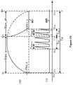
- FIG. 7shows certain dimming-control phase angle diagrams for the lighting system 500 as shown in FIG. 5 according to certain embodiments of the present invention. These diagrams are merely examples, which should not unduly limit the scope of the claims. One of ordinary skill in the art would recognize many variations, alternatives, and modifications.
- the waveform 766represents the output current 566 as a function of dimming-control phase angle ⁇ dim_on
- the waveform 710represents the stage-1 time duration T s1 as a function of dimming-control phase angle ⁇ dim_on
- the waveform 720represents the stage-2 time duration T s2 as a function of dimming-control phase angle ⁇ dim_on
- the waveform 730represents the two-stage total time duration T st as a function of dimming-control phase angle ⁇ dim_on .
- the stage-1 time duration T s1remains equal to T s1_min if the dimming-control phase angle ⁇ dim_on increases from 0° to ⁇ A and from ⁇ A to ⁇ B , the stage-1 time duration T s1 increases (e.g., increases linearly at a constant slope SL 1 ) from T s1_min to T s1_max if the dimming-control phase angle ⁇ dim_on increases from ⁇ B to ⁇ C , and the stage-1 time duration T s1 remains equal to T s1_max if the dimming-control phase angle ⁇ dim_on increases from ⁇ C to 180°.
- T s1_minis equal to zero.
- T s1_minis larger than zero.
- T s1_maxis larger than T s1_min and is also larger than zero.
- the stage-2 time duration T s2remains equal to T s2_min if the dimming-control phase angle ⁇ dim_on increases from 0° to ⁇ A
- the stage-2 time duration T s2increases (e.g., increases linearly at a constant slope SL 2 ) from T s2_min to T s2_max if the dimming-control phase angle ⁇ dim_on increases from ⁇ A to ⁇ B
- the stage-2 time duration T s2remains equal to T s2_max if the dimming-control phase angle ⁇ dim_on increases from ⁇ B to ⁇ C and from ⁇ C to 180°.
- the slope SL 1 and the slope SL 2are different. In another example, the slope SL 1 and the slope SL 2 are equal. In yet another example, ⁇ B is smaller than 90°. In yet another example, T s2_min is equal to zero. In yet another example, T s2_min is larger than zero. In yet another example, T s2_max is larger than T s2_min and is also larger than zero.
- the two-stage total time duration T stis equal to the sum of the stage-1 time duration T s1 and the stage-2 time duration T s2 .
- the two-stage total time duration T stremains equal to T st_min if the dimming-control phase angle ⁇ dim_on increases from 0° to ⁇ A
- the two-stage total time duration T stincreases (e.g., increases linearly at a slope STL 1 ) from T st_min to T st_mid if the dimming-control phase angle ⁇ dim_on increases from ⁇ A to ⁇ B
- the two-stage total time duration T stincreases (e.g., increases linearly at a slope STL 2 ) from T st_mid to T st_max if the dimming-control phase angle ⁇ dim_on increases from ⁇ B to ⁇ C
- the two-stage total time duration T stremains equal to T st_min if the dimming-control
- the slope STL 1is equal to the slope SL 2
- the slope STL 2is equal to the slope SL 1
- the slope STL 1 and the slope STL 2are equal.
- the slope STL 1 and the slope STL 2are not equal.
- T st_minis equal to the sum of T s1_min and T s2_min
- T st_midis equal to the sum of T s1_min and T s2_max
- T st_maxis equal to the sum of T s1_max and T s2_max .
- T st_minis equal to zero.
- T st_minis larger than zero.
- T st_midis larger than T st_min and is also larger than zero, but is smaller than T st_max .
- T st_maxis larger than T st_min and T st_mid , and is also larger than zero.
- the output current 566remains equal to zero if the dimming-control phase angle ⁇ dim_on increases from 0° to ⁇ A , the output current 566 increases (e.g., increases linearly at a slope SL o_1 ) from zero to I o_mid if the dimming-control phase angle ⁇ dim_on increases from ⁇ A to ⁇ B , the output current 566 increases (e.g., increases linearly at a slope SL o_2 ) from I o_mid to I o_max if the dimming-control phase angle ⁇ dim_on increases from ⁇ B to ⁇ C , and the output current 566 remains equal to I o_max if the dimming-control phase angle ⁇ dim_on increases from ⁇ C to 180°.
- the slope SL o_1 and the slope SL o_2are different.
- the slope SL o_1 and the slope SL o_2are equal.
- I o_maxis equal to the magnitude of the output current 566 if the dimmer 510 is removed and the AC input voltage 514 (e.g., VAC) is directly received by the rectifier 520 .
- I o_midis smaller than 10% of I o_max .
- the dimming control of the one or more LEDs 550is performed by changing the stage-2 time duration T s2
- the dimming-control phase angle ⁇ dim_onincreases from ⁇ B to ⁇ C
- the dimming control of the one or more LEDs 550is performed by changing the stage-1 time duration T s1 .
- the slope SL o_1 for the output current 566depends on the slope SL 2 of the stage-2 time duration T s2 .
- the slope SL o_2 for the output current 566depends on the slope SL 1 of the stage-1 time duration T s1 .
- magnitudes of ⁇ A , ⁇ B , and ⁇ Care adjusted, and 0° ⁇ A ⁇ B ⁇ C ⁇ 180° is satisfied.
- magnitudes of ⁇ A , ⁇ B , and ⁇ Care adjusted, and 0° ⁇ A ⁇ B ⁇ C ⁇ 180° is satisfied.
- magnitudes of ⁇ A , ⁇ B , and ⁇ Care adjusted, and 0° ⁇ A ⁇ B ⁇ C ⁇ 180° is satisfied.
- FIG. 8is a simplified diagram showing certain components of the lighting system 500 as shown in FIG. 5 according to one embodiment of the present invention.
- the modulation controller 540includes a dimming control component 800 and a transistor 880 .
- the dimming control component 800includes a signal detector 810 , a mode detector 850 , a stage-timing signal generator 860 , a reference voltage generator 820 , a modulation signal generator 830 , an AND gate 870 , and a driver 840 .
- the modulation signal generator 830is a pulse-width-modulation (PWM) signal generator.
- PWMpulse-width-modulation
- FIG. 8is merely an example, which should not unduly limit the scope of the claims.
- the lighting system 500does not include the TRIAC dimmer 510 .
- the TRIAC dimmer 510is removed from the lighting system 500 , and the AC input voltage 514 (e.g., VAC) is directly received by the rectifier 520 .
- the AC input voltage 514e.g., VAC
- the mode detector 850receives the voltage 571 through the terminal 542 , and determines, based at least in part on the voltage 571 , whether or not the TRIAC dimmer 510 is detected to be included in the lighting system 500 and if the TRIAC dimmer 510 is detected to be included in the lighting system 500 , whether the TRIAC dimmer 510 is a leading-edge TRIAC dimmer or a trailing-edge TRIAC dimmer.
- the mode detector 850generates a mode signal 852 that indicates whether or not the TRIAC dimmer 510 is detected to be included in the lighting system 500 and if the TRIAC dimmer 510 is detected to be included in the lighting system 500 , whether the TRIAC dimmer 510 is a leading-edge TRIAC dimmer or a trailing-edge TRIAC dimmer.
- the mode signal 852is received by the reference voltage generator 820 and the stage-timing signal generator 860 .
- the mode signal 852includes three logic signals 852 a , 852 b , and 852 c .
- the mode signal 852indicates that the TRIAC dimmer 510 is not included in the lighting system 500 .
- the mode signal 852indicates that the TRIAC dimmer 510 is detected to be included in the lighting system 500 and the TRIAC dimmer 510 is a leading-edge TRIAC dimmer.
- the mode signal 852indicates that the TRIAC dimmer 510 is detected to be included in the lighting system 500 and the TRIAC dimmer 510 is a trailing-edge TRIAC dimmer.
- the signal detector 810receives the voltage 571 through the terminal 542 , detects the voltage 571 , and generates a signal 812 .
- the signal 812indicates approximately the magnitude of the dimming-control phase angle ⁇ dim_on of the voltage 571 (e.g., as shown in FIG. 6A , FIG. 6B , and/or FIG. 7 ).
- the signal detector 810generates the signal 812 based at least in part on the voltage 571 . For example, if the voltage 571 becomes larger than a threshold voltage V th_aa , the signal 812 changes from a logic low level to a logic high level. In another example, if the voltage 571 becomes smaller than a threshold voltage V th_bb , the signal 812 changes from the logic high level to the logic low level. In yet another example, the threshold voltage V th_aa and the threshold voltage V th_bb are equal. In yet another example, the threshold voltage V th_aa and the threshold voltage V th_bb are not equal.
- the signal 812changes from the logic high level to the logic low level at time t ⁇ 1 , remains at the logic low level from time t ⁇ 1 to time t 2 , changes from the logic low level to the logic high level at time t 2 , remains at the logic high level from time t 2 to time t 4 , changes from the logic high level to the logic low level at time t 4 , and remains at the logic low level from time t 4 to time t 5 .
- the threshold voltage V th_aais the threshold voltage V th1_a .
- the threshold voltage V th_bbis the threshold voltage V th1_b .
- the signal 812remains at the logic low level from time t 10 to time t 11 , changes from the logic low level to the logic high level at time t 11 , remains at the logic high level from time t 11 to time t 14 , changes from the logic high level to the logic low level at time t 14 , and remains at the logic low level from time t 14 to time t 15 .
- the threshold voltage V th_aais the threshold voltage V th2_a .
- the threshold voltage V th_bbis the threshold voltage V th2_b .
- the reference voltage generator 820receives the mode signal 852 and the signal 812 , and generates a reference voltage 822 (e.g., V ref ). In one embodiment, if the mode signal 852 indicates that the TRIAC dimmer 510 is not included in the lighting system 500 , the reference voltage generator 820 generates the reference voltage 822 (e.g., V ref ) that is a predetermined constant, regardless of the magnitude of the dimming-control phase angle ⁇ dim_on .
- the reference voltage generator 820if the mode signal 852 indicates that the TRIAC dimmer 510 is detected to be included in the lighting system 500 and the TRIAC dimmer 510 is a leading-edge TRIAC dimmer, the reference voltage generator 820 generates the reference voltage 822 (e.g., V ref ).
- the reference voltage 822e.g., V ref
- the reference voltage 822is a predetermined constant, regardless of the magnitude of the dimming-control phase angle ⁇ dim_on .
- the reference voltage 822e.g., V ref
- the reference voltage 822e.g., V ref
- the reference voltage generator 820if the mode signal 852 indicates that the TRIAC dimmer 510 is detected to be included in the lighting system 500 and the TRIAC dimmer 510 is a trailing-edge TRIAC dimmer, the reference voltage generator 820 generates the reference voltage 822 (e.g., V ref ).
- the reference voltage 822e.g., V ref
- the reference voltage 822is a predetermined constant, regardless of the magnitude of the dimming-control phase angle ⁇ dim_on .
- the reference voltage 822e.g., V ref
- the reference voltage 822e.g., V ref
- the reference voltage 822(e.g., V ref ) when the mode signal 852 indicates that the TRIAC dimmer 510 is not included in the lighting system 500 is smaller than the reference voltage 822 (e.g., V ref ) when the mode signal 852 indicates that the TRIAC dimmer 510 is detected to be included in the lighting system 500 .
- the reference voltage 822(e.g., V ref ) is received by the modulation signal generator 830 , which also receives the sensing voltage 575 through the terminal 558 .
- the sensing voltage 575represents the magnitude of the current 561 , which flows through the winding 560 and the resistor 574 .
- the modulation signal generator 830processes the reference voltage 822 (e.g., V ref ) and the sensing voltage 575 and generates a modulation signal 832 .
- the modulation signal generator 830is a pulse-width-modulation (PWM) signal generator
- the modulation signal 832is a pulse-width-modulation (PWM) signal.
- the modulation signal generator 830determines an integral of the reference voltage 822 (e.g., V ref ) over time, converts the integral to an intermediate voltage that is proportional to the integral, and determines whether the sensing voltage 575 reaches or exceeds the intermediate voltage.
- the modulation signal generator 830changes the modulation signal 832 from a logic high level to a logic low level to cause the end of the pulse width for the switching cycle if the pulse width is not larger than the maximum pulse width predetermined by the modulation controller 540 .
- the sensing voltage 575reaches or exceeds the intermediate voltage fast enough so that the pulse width ends before the pulse width becomes larger than a maximum pulse width predetermined by the modulation controller 540 .
- the sensing voltage 575cannot reach or exceed the intermediate voltage fast enough, and the pulse width of the modulation signal 832 for the switching cycle is set equal to the maximum pulse width predetermined by the modulation controller 540 .
- the modulation signal 832is received by the AND gate 870 .
- the modulation signal generator 830processes the sensing voltage 575 , detects whether the capacitor 530 has been completely discharged based at least in part on the sensing voltage 575 , and when the capacitor 530 has been detected to be completely discharged, generate a timing signal 834 that indicates the capacitor 530 has been completely discharged.
- the timing signal 834indicates the capacitor 530 becomes completely discharged at time t 6 as shown in FIG. 6A .
- the timing signal 834is received by the stage-timing signal generator 860 .
- the modulation signal generator 830processes the sensing voltage 575 , detects whether a pulse width of the modulation signal 832 for a switching cycle is set equal to the maximum pulse width predetermined by the modulation controller 540 , and if the pulse width of the modulation signal 832 is set equal to the maximum pulse width, generate the timing signal 834 that indicates the capacitor 530 has been completely discharged. For example, the timing signal 834 indicates the capacitor 530 becomes completely discharged at time t 6 as shown in FIG. 6A . In another example, the timing signal 834 is received by the stage-timing signal generator 860 .
- the stage-timing signal generator 860receives the mode signal 852 , the signal 812 and the timing signal 834 and generates a stage-timing signal 862 based at least in part on the mode signal 852 , the signal 812 and/or the timing signal 834 .
- the stage-timing signal 862is received by the AND gate 870 .
- the stage-timing signal 862indicates the beginning and the end of the stage-1 time duration T s1 and the beginning and the end of the stage-2 time duration T s2 .
- the stage-timing signal generator 860changes the stage-timing signal 862 from the logic low level to the logic high level at time t 2 , indicating the beginning of the stage-1 time duration T s1 .
- the stage-timing signal generator 860changes the stage-timing signal 862 from the logic high level to the logic low level at time t 3 , indicating the end of the stage-1 time duration T s1 , if the stage-1 time duration T s1 is not larger than T s1_max in magnitude as shown by the waveform 710 of FIG. 7 .
- the stage-timing signal generator 860changes the stage-timing signal 862 from the logic low level to the logic high level at time t 4 , indicating the beginning of the stage-2 time duration T s2 .
- the stage-timing signal generator 860changes the stage-timing signal 862 from the logic high level to the logic low level at time t 6 , indicating the end of the stage-2 time duration T s2 , if the stage-2 time duration T s2 is not larger than T s2_max in magnitude as shown by the waveform 720 of FIG. 7 .
- the stage-timing signal 862indicates the beginning of the stage-1 time duration T s1 and the end of the stage-2 time duration T s2 .
- the stage-timing signal generator 860changes the stage-timing signal 862 from the logic low level to the logic high level at time t 12 , indicating the beginning of the stage-1 time duration T s1 .
- the stage-timing signal generator 860changes the stage-timing signal 862 from the logic high level to the logic low level at time t 14 , indicating the end of the stage-2 time duration T s2 .
- the stage-1 time duration T s1is not larger than T s1_max in magnitude as shown by the waveform 710 of FIG. 7
- the stage-2 time duration T s2is not larger than T s2_max in magnitude as shown by the waveform 720 of FIG. 7 .
- the stage-timing signal 862is the same as the signal 812 . For example, if the voltage 571 becomes larger than the threshold voltage V th_aa , the stage-timing signal 862 changes from the logic low level to the logic high level. In another example, if the voltage 571 becomes smaller than the threshold voltage V th_bb , the stage-timing signal 862 changes from the logic high level to the logic low level.
- the stage-timing signal 862remains at the logic high level from a time when the voltage 571 becomes larger than the threshold voltage V th_aa to a time when the voltage 571 becomes smaller than the threshold voltage V th_bb for the first time since the voltage 571 becomes larger than the threshold voltage V th_aa . In yet another example, the stage-timing signal 862 remains at the logic low level from a time when the voltage 571 becomes smaller than the threshold voltage V th_bb to a time when the voltage 571 becomes larger than the threshold voltage V th_aa for the first time since the voltage 571 becomes smaller than the threshold voltage V th_bb .
- the AND gate 870receives the modulation signal 832 and the stage-timing signal 862 and generates a control signal 872 based at least in part on the modulation signal 832 and the stage-timing signal 862 .
- the stage-timing signal 862remains at the logic high level during the stage-1 time duration T s1 and during the stage-2 time duration T s2 , and the stage-timing signal 862 remains at the logic low level outside the stage-1 time duration T s1 and the stage-2 time duration T s2 .
- the control signal 872is the same as the modulation signal 832 .
- the control signal 872remains at the logic low level.
- the stage-timing signal 862remains at the logic high level throughout entire each half cycle of the voltage 571 .
- the voltage 571has a phase angel (e.g., ⁇ ), which changes from 0° to 180° for a half cycle of the voltage 571 and then changes from 180° to 360° for another half cycle of the voltage 571 .
- the control signal 872is the same as the modulation signal 832 .
- the modulation signal generator 830operates under quasi-resonant (QR) constant-current (CC) mode.
- QRquasi-resonant
- CCconstant-current
- each half cycle of the voltage 571includes multiple switching cycles of the modulation signal 832 .
- each switching cycle of the modulation signal 832includes an on-time period and an off-time period.
- the on-time period of the modulation signal 832remains constant in magnitude but the off-time period of the modulation signal 832 changes in magnitude, in order to achieve satisfactory power factor (PF).
- the driver 840receives the control signal 872 and generates a drive signal 842 .
- the control signal 872is at the logic high level
- the drive signal 842is also at the logic high level.
- the driver 840outputs the drive signal 842 to the transistor 880 .
- the transistor 880is turned on if the drive signal 842 is at the logic high level, and the transistor 880 is turned off if the drive signal 842 is at the logic low level.
- the transistor 562 and the transistor 880are turned on, the current 561 flows through the winding 560 , the transistor 562 , the controller terminal 554 , the transistor 880 , the controller terminal 558 , and the resistor 574 .
- the transistor 880becomes turned off when the transistor 562 is still turned on, the transistor 562 also becomes turned off and the winding 560 starts to discharge.
- the transistor 880becomes turned on when the transistor 562 is still turned off, the transistor 562 also becomes turned on and the winding 560 starts to charge.
- the lighting system 500includes a quasi-resonant system with a buck-boost topology according to certain embodiments.
- the output current 566 of the quasi-resonant systemis received by the one or more LEDs 550 and is determined as follows:
- I o1 2 ⁇ V ref R cs ⁇ T s ⁇ ⁇ 1 + T s ⁇ ⁇ 2 T M ( Equation ⁇ ⁇ 2 )
- I orepresents the output current 566 of the quasi-resonant system of the lighting system 500 .
- V refrepresents the reference voltage 822 (e.g., the reference voltage received by an internal error amplifier of the modulation controller 540 )
- R csrepresents the resistance of the resistor 574 .
- T s1represents a stage-1 time duration
- T s2represents a stage-2 time duration.
- T Mrepresents one period of the voltage 571 .
- one period of the voltage 571is equal to half period of the AC input voltage 514 (e.g., VAC).
- FIG. 9Ashows certain timing diagrams for the lighting system 500 as shown in FIG. 5 and FIG. 6A if the TRIAC dimmer 510 is a leading-edge TRIAC dimmer according to one embodiment of the present invention.
- the waveform 671represents the voltage 571 as a function of time as shown in FIG. 6A
- the waveform 675represents the sensing voltage 575 as a function of time as shown in FIG. 6A
- the waveform 962represents the stage-timing signal 862 as a function of time.
- the TRIAC dimmer 510is a leading-edge TRIAC dimmer, which clips part of the waveform that corresponds to the phase angel from ⁇ i to ⁇ c .
- ⁇ c minus ⁇ iis equal to ⁇ dim_off , which corresponds to a time duration (e.g., T dim_off ) when the TRIAC dimmer 510 is not fired on.
- the unclipped part of the waveformcorresponds to the phase angel from ⁇ c to ⁇ f .
- ⁇ f minus ⁇ cis equal to ⁇ dim_on , which corresponds to a time duration (e.g., T dim_on ) when the TRIAC dimmer 510 is fired on.
- time t 5is approximately equal to time t 4
- the phase angel of approximatelycorresponds to time t 4
- the time duration T dim_off when the TRIAC dimmer 510 is not fired onstarts at time t 0 and ends at t 2 .
- the time duration T dim_on when the TRIAC dimmer 510 is fired onstarts at time t 2 and ends approximately at t 4 .
- one period T M of the voltage 571starts at time t 0 and ends approximately at time t 4 .
- the stage-1 time duration T s1starts at time t 2 and ends at time t 3 .
- the stage-timing signal 862changes from a logic low level to a logic high level at time t 2 , remains at the logic high level from time t 2 to time t 3 , and changes from the logic high level back to the logic low level at time t 3 .
- the stage-2 time duration T s2starts at time t 4 and ends at time t 6 .
- the stage-timing signal 862changes from the logic low level to the logic high level at time t 4 , remains at the logic high level from time t 4 to time t 6 , and changes from the logic high level back to the logic low level at time t 6 .
- time t 4is after time t 3 .
- the stage-1 time duration T s1starts at time t 2 , which is the end of the time duration T dim_off when the TRIAC dimmer 510 is not fired on.
- the signal 812changes from the logic low level to the logic high at time t 2
- the stage-timing signal generator 860changes the stage-timing signal 862 from the logic low level to the logic high level at time t 2 , indicating the beginning of the stage-1 time duration T s1 .
- the stage-1 time duration T s1ends at time t 3 , which is the end of a predetermined time duration T P from the time when the voltage 571 becomes smaller than the threshold voltage V th1_b .
- the signal 812changes from the logic high level to the logic low level at time t ⁇ 1
- the stage-timing signal generator 860after the predetermined time duration T P , changes the stage-timing signal 862 from the logic high level to the logic low level at time t 3 , indicating the end of the stage-1 time duration T s1 .
- the stage-1 time duration T s1is larger than or equal to zero but smaller than or equal to T s1_max in magnitude, as shown by the waveform 710 of FIG. 7 .
- time t 3is larger than or equal to time t 2 in magnitude.
- time t 3 minus time t 2is smaller than or equal to T s1_max in magnitude.
- time t ⁇ 1is approximately equal to time t 4 , and the following can be obtained: T dim_off T s1 ⁇ T P (Equation 4) where T dim_off represents the time duration when the TRIAC dimmer 510 is not fired on, and T s1 represents a stage-1 time duration. Additionally, T P represents a predetermined time duration. For example, the stage-1 time duration T s1 satisfies Equation 4, and the stage-1 time duration T s1 is also larger than or equal to zero but smaller than or equal to T s1_max in magnitude as shown by the waveform 710 of FIG. 7 .
- T s1represents the stage-1 time duration
- T dim_onrepresents the time duration when the TRIAC dimmer 510 is fired on.
- T Mrepresents one period of the voltage 571
- T Prepresents a predetermined time duration.
- the stage-1 time duration T s1satisfies Equation 5
- the stage-1 time duration T s1is also larger than zero but smaller than T s1_max as shown by the waveform 710 of FIG. 7 .
- T Mrepresents one period of the voltage 571
- T Prepresents a predetermined time duration.
- the stage-1 time duration T s1satisfies Equation 7, and the stage-1 time duration T s1 is also larger than or equal to zero but smaller than or equal to T s1_max in magnitude, as shown by the waveform 710 of FIG. 7 .
- the stage-2 time duration T s2starts at time t 4 .
- the signal 812changes from the logic high level to the logic low at time t 4
- the stage-timing signal generator 860changes the stage-timing signal 862 from the logic low level to the logic high level at time t 4 , indicating the beginning of the stage-2 time duration T s2 .
- the stage-2 time duration T s2ends at time t 6 , which is the time when the capacitor 530 is completely discharged.
- the timing signal 834indicates that the capacitor 530 becomes completely discharged at time t 6 , and in response, the stage-timing signal generator 860 changes the stage-timing signal 862 from the logic high level to the logic low level at time t 6 , indicating the end of the stage-2 time duration T s2 .
- the stage-2 time duration T s2is larger than or equal to zero but smaller than or equal to T s2_max in magnitude, as shown by the waveform 720 of FIG. 7 .
- time t 6is larger than or equal to time t 4 in magnitude.
- time t 6 minus time t 4is smaller than or equal to T s2_max in magnitude.
- each period (e.g., corresponding to each T M ) of the voltage 571there are a stage-1 time duration (e.g., T s1 ) and a stage-2 time duration (e.g., T s2 ) according to certain embodiments.
- the stage-1 time duration T s1starts at time t 2 and ends at time t 3
- the stage-2 time duration T s2starts at time t 4 and ends at time t 6 .
- the stage-2 time duration T s2starts at time t ⁇ 1 and ends at time t 1 .
- the stage-timing signal 862changes from the logic low level to the logic high level at time t ⁇ 1 , remains at the logic high level from time t ⁇ 1 to time t 1 , changes from the logic high level to the logic low level at time t 1 , remains at the logic low level from time t 1 to time t 2 , changes from the logic low level to the logic high level at time t 2 , remains at the logic high level from time t 2 to time t 3 , changes from the logic high level to the logic low level at time t 3 , remains at the logic low level from time t 3 to time t 4 , changes from the logic low level to the logic high level at time t 4 , remains at the logic high level from time t 4 to t 6 , and changes from the logic high level to the logic low level at time t 6 .
- the stage-1 time duration(e.g., T s1 from time t 2 to time t 3 ) falls within the time duration when the TRIAC dimmer 510 is fired on (e.g., T dim_on from time t 2 to time t 5 ), and the stage-2 time duration (e.g., T s2 from time t 4 to time t 6 ) at least mostly falls outside of the time duration when the TRIAC dimmer 510 is fired on (e.g., T dim_on from time t 2 to time t 5 ).
- the sensing voltage 575ramps up and down and the current 561 also ramps up and down.
- the sensing voltage 575remains equal to zero.
- the current 561charges the capacitor 532 .
- the sensing voltage 575ramps up and down and the current 561 also ramps up and down.
- FIG. 9Bshows certain timing diagrams for the lighting system 500 as shown in FIG. 5 and FIG. 6B if the TRIAC dimmer 510 is a trailing-edge TRIAC dimmer according to another embodiment of the present invention.
- the waveform 681represents the voltage 571 as a function of time as shown in FIG. 6B
- the waveform 675represents the sensing voltage 575 as a function of time as shown in FIG. 6B
- the waveform 972represents the stage-timing signal 862 as a function of time.
- the TRIAC dimmer 510is a trailing-edge TRIAC dimmer, which clips part of the waveform that corresponds to the phase angel from ⁇ c to ⁇ f .
- ⁇ f minus ⁇ cis equal to ⁇ dim_off , which corresponds to a time duration (e.g., T dim_off ) when the TRIAC dimmer 510 is not fired on.
- the unclipped part of the waveformcorresponds to the phase angel from ⁇ i to ⁇ c .
- ⁇ c minus ⁇ iis equal to ⁇ dim_on , which corresponds to a time duration (e.g., T dim_on ) when the TRIAC dimmer 510 is fired on.
- time t 10is approximately equal to time t 11
- the phase angel ⁇ iapproximately corresponds to time t 11 .
- the time duration T dim_off when the TRIAC dimmer 510 is not fired onstarts at time t 13 and ends at t 15 .
- the time duration T dim_on when the TRIAC dimmer 510 is fired onstarts at approximately time t 11 and ends at t 13 .
- one period T M of the voltage 571starts approximately at time t 11 and ends at time t 15 .
- the stage-1 time duration T s1starts at time t 12 and ends at time t 13 .
- the stage-timing signal 862changes from a logic low level to a logic high level at time t 12 , remains at the logic high level from time t 12 to time t 13 .
- the stage-2 time duration T s2starts at time t 13 and ends at time t 14 .
- the stage-timing signal 862remains at the logic high level from time t 13 to time t 14 , and changes from the logic high level back to the logic low level at time t 14 .
- the combination of the stage-1 time duration T s1 and the stage-2 time duration T s2starts at time t 12 and ends at time t 14 .
- the stage-timing signal 862changes from the logic low level to the logic high level at time t 12 , remains at the logic high level from time t 12 to time t 14 , and changes from the logic high level back to the logic low level at time t 14 .
- the stage-1 time duration T s1starts at time t 12 , which is the end of a predetermined time duration T Q from the time when the voltage 571 becomes larger than the threshold voltage V th2_a .
- the phase signal 812changes from the logic low level to the logic high level at time t 11
- the stage-timing signal generator 860after the predetermined time duration T Q , changes the stage-timing signal 862 from the logic low level to the logic high level at time t 12 , indicating the beginning of the stage-1 time duration T s1 .
- the stage-1 time duration T s1ends at time t 12 , which is the end of the time duration T dim_on when the TRIAC dimmer 510 is fired on.
- the stage-1 time duration T s1is larger than or equal to zero but smaller than or equal to T s1_max in magnitude, as shown by the waveform 710 of FIG. 7 .
- time t 13is larger than or equal to time t 12 in magnitude.
- time t 13 minus time t 12is smaller than or equal to T s1_max in magnitude.
- T Q +T s1 ⁇ T dim_on(Equation 9) where T Q represents a predetermined time duration, and T s1 represents a stage-1 time duration. Additionally, T dim_on represents the time duration when the TRIAC dimmer 510 is fired on.
- the stage-1 time duration T s1satisfies Equation 9, and the stage-1 time duration T s1 is also larger than or equal to zero but smaller than or equal to T s1_max in magnitude as shown by the waveform 710 of FIG. 7 .
- T s1 ⁇ T dim_on ⁇ T Q(Equation 10) where T s1 represents the stage-1 time duration, and T dim_on represents the time duration when the TRIAC dimmer 510 is fired on. Additionally, T Q represents a predetermined time duration. For example, the stage-1 time duration T s1 satisfies Equation 10, and the stage-1 time duration T s1 is also larger than zero but smaller than T s1_max as shown by the waveform 710 of FIG. 7 .
- the stage-1 time duration T s1satisfies Equation 12, and the stage-1 time duration T s1 is also larger than or equal to zero but smaller than or equal to T s1_max in magnitude, as shown by the waveform 710 of FIG. 7 .
- the stage-2 time duration T s2starts at time t 13 , which is the end of the stage-1 time duration T s1 .
- the stage-timing signal generator 860keeps the stage-timing signal 862 at the logic high level.
- the stage-2 time duration T s2ends at time t 14 .
- the signal 812changes from the logic high level to the logic low at time t 14
- the stage-timing signal generator 860changes the stage-timing signal 862 from the logic high level to the logic low level at time t 14 , indicating the end of the stage-2 time duration T s2 .
- the stage-2 time duration T s2is larger than or equal to zero but smaller than or equal to T s2_max in magnitude, as shown by the waveform 720 of FIG. 7 .
- time t 14is larger than or equal to time t 13 in magnitude.
- time t 14 minus time t 13is smaller than or equal to T s2_max in magnitude.
- the stage-timing signal 862changes from the logic low level to the logic high level at time t 12 , remains at the logic high level from time t 12 to time t 14 , and changes from the logic high level back to the logic low level at time t 14 .
- time t 12is no later than time t 14 .
- each period (e.g., corresponding to each T M ) of the voltage 571there are a stage-1 time duration (e.g., T s1 ) and a stage-2 time duration (e.g., T s2 ) according to certain embodiments.
- the stage-1 time duration T s1starts at time t 12 and ends at time t 13
- the stage-2 time duration T s2starts at time t 13 and ends at time t 14 .
- the stage-timing signal 862changes from the logic low level to the logic high level at time t 12 , remains at the logic high level from time t 12 to time t 14 , and changes from the logic high level to the logic low level at time t 14 .
- the stage-1 time duration(e.g., T s1 from time t 12 to time t 13 ) falls within the time duration when the TRIAC dimmer 510 is fired on (e.g., T dim_on from time t 10 to time t 13 ), and the stage-2 time duration (e.g., T s2 from time t 13 to time t 14 ) falls within the time duration when the TRIAC dimmer 510 is not fired on (e.g., T dim_off from time t 13 to time t 15 ).
- the sensing voltage 575ramps up and down and the current 561 also ramps up and down.
- the sensing voltage 575remains equal to zero.
- the current 561charges the capacitor 532 .
- stage-based dimmer control systems and methodswith high compatibility, low costs, and/or high efficiency.
- the stage-based dimmer control systems and methodsdo not include a bleeder; hence the system layouts are simplified with high compatibility achieved.
- the stage-based dimmer control systems and methodsuse one or more control mechanisms in order to reduce bill of materials (BOM), raise energy efficiency, and lower system costs, while providing users with satisfactory dimming effects for light emitting diodes.
- BOMbill of materials
- stage-based dimmer control systems and methodsuse a stage-1 time duration (e.g., T s1 ) and a stage-2 time duration (e.g., T s2 ), and each of these time durations is a function of dimming-control phase angle ⁇ dim_on as shown in FIG. 7 .
- a system controllerfor a lighting system (e.g., the lighting system 500 ) includes a first controller terminal (e.g., the controller terminal 542 ) configured to receive a first signal (e.g., the voltage 571 ), and a second controller terminal (e.g., the controller terminal 552 ) coupled to a first transistor terminal of a transistor (e.g., the gate terminal of the transistor 562 ).
- the transistorfurther includes a second transistor terminal (e.g., the drain terminal of the transistor 562 ) and a third transistor terminal (e.g., the source terminal of the transistor 562 ).
- the second transistor terminalis coupled to a first winding terminal of a winding (e.g., the winding 560 ), and the winding (e.g., the winding 560 ) further includes a second winding terminal coupled to a capacitor (e.g., the capacitor 530 ).
- the system controllerincludes a third controller terminal (e.g., the controller terminal 554 ) coupled to the third transistor terminal of the transistor (e.g., the source terminal of the transistor 562 ), and a fourth controller terminal (e.g., the controller terminal 558 ) coupled to a resistor (e.g., the resistor 574 ) and configured to receive a second signal (e.g., the sensing voltage 575 ).
- the second signalrepresents a magnitude of a current (e.g., the current 561 ) flowing through at least the winding (e.g., the winding 560 ), the third controller terminal (e.g., the controller terminal 554 ), the fourth controller terminal (e.g., the controller terminal 558 ), and the resistor (e.g., the resistor 574 ).
- a currente.g., the current 561
- the third controller terminale.g., the controller terminal 554
- the fourth controller terminale.g., the controller terminal 558
- the resistore.g., the resistor 574
- the system controller(e.g., the modulation controller 540 ) is configured to: in response to the first signal (e.g., the voltage 571 ) becoming larger than a first threshold (e.g., the threshold voltage V th1_a ) in magnitude at a first time (e.g., the time t 2 ), cause the second signal (e.g., the sensing voltage 575 ) to ramp up and down during a first duration of time (e.g., the stage-1 time duration T s1 ); and in response to the first signal (e.g., the voltage 571 ) becoming smaller than a second threshold (e.g., the threshold voltage V th1_b ) in magnitude at a third time (e.g., the time t 4 ), cause the second signal (e.g., the sensing voltage 575 ) to ramp up and down during a second duration of time (e.g., the stage-2 time duration T s2 ).
- a first thresholde.g., the threshold
- the first duration of time(e.g., the stage-1 time duration T s1 ) starts at the first time (e.g., the time t 2 ) and ends at a second time (e.g., the time t 3 ).
- the second duration of time(e.g., the stage-2 time duration T s2 ) starts at the third time (e.g., the time t 4 ) and ends at a fourth time (e.g., the time t 6 ).
- the system controller(e.g., the modulation controller 540 ) is further configured to cause the second signal (e.g., the sensing voltage 575 ) to remain equal to a constant magnitude from the second time (e.g., the time t 3 ) to the third time (e.g., the time t 4 ).
- the first time(e.g., the time t 2 ) is earlier than the second time (e.g., the time t 3 )
- the second time(e.g., the time t 3 ) is earlier than the third time (e.g., the time t 4 )
- the third timee.g., the time t 4
- the fourth timee.g., the time t 6
- the system controller(e.g., the modulation controller 540 ) is implemented according to at least FIG. 5 , FIG. 6A , and/or FIG. 9A .
- the system controller(e.g., the modulation controller 540 ) is further configured to: in response to the first signal (e.g., the voltage 571 ) becoming smaller than the second threshold (e.g., the threshold voltage V th1_b ) in magnitude at a previous time (e.g., the time t ⁇ 1 ) earlier than the first time (e.g., the time t 2 ), determine the second time (e.g., the time t 3 ) to be a predetermined time duration (e.g., the predetermined time duration T P ) after the previous time (e.g., the time t ⁇ 1 ).
- the first signale.g., the voltage 571
- the second thresholde.g., the threshold voltage V th1_b
- the fourth timeis a time when the capacitor (e.g., the capacitor 530 ) becomes completely discharged.
- the first thresholde.g., the threshold voltage V th1_a
- the second thresholde.g., the threshold voltage V th1_b
- the first thresholde.g., the threshold voltage V th1_a
- the second thresholde.g., the threshold voltage V th1_b
- the constant magnitudeis equal to zero.
- each of the first controller terminale.g., the controller terminal 542
- the second controller terminale.g., the controller terminal 552
- the third controller terminale.g., the controller terminal 554
- the fourth controller terminale.g., the controller terminal 558
- a system controllerfor a lighting system (e.g., the lighting system 500 ) includes a first controller terminal (e.g., the controller terminal 542 ) configured to receive a first signal (e.g., the voltage 571 ), and a second controller terminal (e.g., the controller terminal 552 ) coupled to a first transistor terminal of a transistor (e.g., the gate terminal of the transistor 562 ).
- a first controller terminale.g., the controller terminal 542
- a second controller terminale.g., the controller terminal 552
- the transistorfurther includes a second transistor terminal (e.g., the drain terminal of the transistor 562 ) and a third transistor terminal (e.g., the source terminal of the transistor 562 ), and the second transistor terminal is coupled to a winding (e.g., the winding 560 ).
- a second transistor terminale.g., the drain terminal of the transistor 562
- a third transistor terminale.g., the source terminal of the transistor 562
- the second transistor terminalis coupled to a winding (e.g., the winding 560 ).
- the system controller(e.g., the modulation controller 540 ) further includes a third controller terminal (e.g., the controller terminal 554 ) coupled to the third transistor terminal of the transistor (e.g., the source terminal of the transistor 562 ), and a fourth controller terminal (e.g., the controller terminal 558 ) coupled to a resistor (e.g., the resistor 574 ) and configured to receive a second signal (e.g., the sensing voltage 575 ).
- a third controller terminale.g., the controller terminal 554
- the fourth controller terminale.g., the controller terminal 558
- the second signalrepresents a magnitude of a current (e.g., the current 561 ) flowing through at least the winding (e.g., the winding 560 ), the third controller terminal (e.g., the controller terminal 554 ), the fourth controller terminal (e.g., the controller terminal 558 ), and the resistor (e.g., the resistor 574 ).
- a currente.g., the current 561
- the third controller terminale.g., the controller terminal 554
- the fourth controller terminale.g., the controller terminal 558
- the resistore.g., the resistor 574
- the system controller(e.g., the modulation controller 540 ) is configured to: in response to the first signal (e.g., the voltage 571 ) becoming larger than a first threshold (e.g., the threshold voltage V th2_a ) in magnitude at a first time (e.g., the time t 11 ), cause the second signal (e.g., the sensing voltage 575 ) to ramp up and down during a duration of time (e.g., the two-stage total time duration T st ).
- a first thresholde.g., the threshold voltage V th2_a
- the duration of time(e.g., the two-stage total time duration T st ) starts at a second time (e.g., the time t 12 ) and ends at a third time (e.g., the time t 14 ).
- the third time(e.g., the time t 14 ) is a time when the first signal (e.g., the voltage 571 ) becomes smaller than a second threshold (e.g., the threshold voltage V th2_b ) in magnitude.
- the system controller(e.g., the modulation controller 540 ) is further configured to cause the second signal (e.g., the sensing voltage 575 ) to remain equal to a constant magnitude from the first time (e.g., the time t 11 ) to the second time (e.g., the time t 12 ).
- the first time(e.g., the time t 11 ) is earlier than the second time (e.g., the time t 12 ), and the second time (e.g., the time t 12 ) is earlier than the third time (e.g., the time t 14 ).
- the system controllere.g., the modulation controller 540
- the system controlleris implemented according to at least FIG. 5 , FIG. 6B , and/or FIG. 9B .
- the system controller(e.g., the modulation controller 540 ) is further configured to: in response to the first signal (e.g., the voltage 571 ) becoming larger than the first threshold (e.g., the threshold voltage V th2_a ) in magnitude at the first time (e.g., the time t 11 ), determine the second time (e.g., the time t 12 ) to be a predetermined time duration (e.g., the predetermined time duration T Q ) after the first time (e.g., the time t 11 ).
- the first thresholde.g., the threshold voltage V th2_a
- the second thresholde.g., the threshold voltage V th2_b
- the first thresholde.g., the threshold voltage V th2_a
- the second thresholde.g., the threshold voltage V th2_b
- the constant magnitudeis equal to zero.
- a system controllerfor a lighting system (e.g., the lighting system 500 ) includes a first controller terminal (e.g., the controller terminal 542 ) configured to receive a first signal (e.g., the voltage 571 ). The first signal is related to a dimming-control phase angle (e.g., ⁇ dim_on ). Additionally, the system controller (e.g., the modulation controller 540 ) includes a second controller terminal (e.g., the controller terminal 552 ) coupled to a first transistor terminal of a transistor (e.g., the gate terminal of the transistor 562 ).
- the transistorfurther includes a second transistor terminal (e.g., the drain terminal of the transistor 562 ) and a third transistor terminal (e.g., the source terminal of the transistor 562 ), and the second transistor terminal is coupled to a winding (e.g., the winding 560 ).
- a second transistor terminale.g., the drain terminal of the transistor 562
- a third transistor terminale.g., the source terminal of the transistor 562
- the second transistor terminalis coupled to a winding (e.g., the winding 560 ).
- the system controller(e.g., the modulation controller 540 ) includes a third controller terminal (e.g., the controller terminal 554 ) coupled to the third transistor terminal of the transistor (e.g., the source terminal of the transistor 562 ), and a fourth controller terminal (e.g., the controller terminal 558 ) coupled to a resistor (e.g., the resistor 574 ) and configured to receive a second signal (e.g., the sensing voltage 575 ).
- a third controller terminale.g., the controller terminal 554
- the fourth controller terminale.g., the controller terminal 558
- the second signalrepresents a magnitude of a current (e.g., the current 561 ) flowing through at least the winding (e.g., the winding 560 ), the third controller terminal (e.g., the controller terminal 554 ), the fourth controller terminal (e.g., the controller terminal 558 ), and the resistor (e.g., the resistor 574 ).
- a currente.g., the current 561
- the third controller terminale.g., the controller terminal 554
- the fourth controller terminale.g., the controller terminal 558
- the resistore.g., the resistor 574
- the system controller(e.g., the modulation controller 540 ) is configured to, in response to the first signal (e.g., the voltage 571 ) satisfying one or more predetermined conditions: cause the second signal (e.g., the sensing voltage 575 ) to ramp up and down during a first duration of time (e.g., the stage-1 time duration T s1 ); and cause the second signal (e.g., the sensing voltage 575 ) to ramp up and down during a second duration of time (e.g., the stage-2 time duration T s2 ).
- the first signale.g., the voltage 571
- the system controllere.g., the modulation controller 540
- the system controlleris configured to, in response to the first signal (e.g., the voltage 571 ) satisfying one or more predetermined conditions: cause the second signal (e.g., the sensing voltage 575 ) to ramp up and down during a first duration of time (e.g., the stage-1 time duration T s1
- the first duration of time(e.g., the stage-1 time duration T s1 ) starts at a first time and ends at a second time, and the second time is the same as or later than the first time.
- the second duration of time(e.g., the stage-2 time duration T s2 ) starts at a third time and ends at a fourth time, and the fourth time is the same as or later than the third time.
- the system controller(e.g., the modulation controller 540 ) is further configured to: in response to the dimming-control phase angle (e.g., ⁇ dim_on ) increasing from a first angle magnitude (e.g., 0°) to a second angle magnitude (e.g., ⁇ B), keep the first duration of time at a first predetermined constant; in response to the dimming-control phase angle (e.g., ⁇ dim_on ) increasing from the second angle magnitude (e.g., ⁇ B ) to a third angle magnitude (e.g., ⁇ C ), increase the first duration of time; and in response to the dimming-control phase angle (e.g., ⁇ dim_on ) increasing from the third angle magnitude (e.g., ⁇ C ) to a fourth angle magnitude (e.g., 180°), keep the first duration of time at a second predetermined constant (e.g., T s1_max ).
- the system controllere.g., the
- the second timeis earlier than the third time. In yet another example, the second time is the same as the third time. In yet another example, the first angle magnitude is equal to 0°, and the fourth angle magnitude is equal to 180°. In yet another example, the first predetermined constant is equal to zero. In yet another example, the system controller (e.g., the modulation controller 540 ) is further configured to, in response to the dimming-control phase angle (e.g., ⁇ dim_on ) increasing from the second angle magnitude (e.g., ⁇ B ) to the third angle magnitude (e.g., ⁇ C ), increase the first duration of time linearly with the increasing dimming-control phase angle at a constant slope (e.g., the slope SL 1 ). In yet another example, the second predetermined constant (e.g., T s1_max ) is larger than zero.
- the dimming-control phase anglee.g., ⁇ dim_on
- the third angle magnitudee.g., ⁇ C
- a system controllerfor a lighting system (e.g., the lighting system 500 ) includes a first controller terminal (e.g., the controller terminal 542 ) configured to receive a first signal (e.g., the voltage 571 ). The first signal is related to a dimming-control phase angle (e.g., ⁇ dim_on ). Additionally, the system controller (e.g., the modulation controller 540 ) includes a second controller terminal (e.g., the controller terminal 552 ) coupled to a first transistor terminal of a transistor (e.g., the gate terminal of the transistor 562 ).
- the transistorfurther includes a second transistor terminal (e.g., the drain terminal of the transistor 562 ) and a third transistor terminal (e.g., the source terminal of the transistor 562 ), and the second transistor terminal is coupled to a winding (e.g., the winding 560 ).
- a second transistor terminale.g., the drain terminal of the transistor 562
- a third transistor terminale.g., the source terminal of the transistor 562
- the second transistor terminalis coupled to a winding (e.g., the winding 560 ).
- the system controller(e.g., the modulation controller 540 ) includes a third controller terminal (e.g., the controller terminal 554 ) coupled to the third transistor terminal of the transistor (e.g., the source terminal of the transistor 562 ), and a fourth controller terminal (e.g., the controller terminal 558 ) coupled to a resistor (e.g., the resistor 574 ) and configured to receive a second signal (e.g., the sensing voltage 575 ).
- a third controller terminale.g., the controller terminal 554
- the fourth controller terminale.g., the controller terminal 558
- the second signalrepresents a magnitude of a current (e.g., the current 561 ) flowing through at least the winding (e.g., the winding 560 ), the third controller terminal (e.g., the controller terminal 554 ), the fourth controller terminal (e.g., the controller terminal 558 ), and the resistor (e.g., the resistor 574 ).
- a currente.g., the current 561
- the third controller terminale.g., the controller terminal 554
- the fourth controller terminale.g., the controller terminal 558
- the resistore.g., the resistor 574
- the system controller(e.g., the modulation controller 540 ) is configured to, in response to the first signal (e.g., the voltage 571 ) satisfying one or more predetermined conditions: cause the second signal (e.g., the sensing voltage 575 ) to ramp up and down during a first duration of time (e.g., the stage-1 time duration T s1 ); and cause the second signal (e.g., the sensing voltage 575 ) to ramp up and down during a second duration of time (e.g., the stage-2 time duration T s2 ).
- the first signale.g., the voltage 571
- the system controllere.g., the modulation controller 540
- the system controlleris configured to, in response to the first signal (e.g., the voltage 571 ) satisfying one or more predetermined conditions: cause the second signal (e.g., the sensing voltage 575 ) to ramp up and down during a first duration of time (e.g., the stage-1 time duration T s1
- the first duration of time(e.g., the stage-1 time duration T s1 ) starts at a first time and ends at a second time, and the second time is the same as or later than the first time.
- the second duration of time(e.g., the stage-2 time duration T s2 ) starts at a third time and ends at a fourth time, and the fourth time is the same as or later than the third time.
- the system controller(e.g., the modulation controller 540 ) is further configured to: in response to the dimming-control phase angle (e.g., ⁇ dim_on ) increasing from a first angle magnitude (e.g., 0°) to a second angle magnitude (e.g., GA), keep the second duration of time at a first predetermined constant; in response to the dimming-control phase angle (e.g., ⁇ dim_on ) increasing from the second angle magnitude (e.g., ⁇ A ) to a third angle magnitude (e.g., ⁇ B), increase the second duration of time; and in response to the dimming-control phase angle (e.g., ⁇ dim_on ) increasing from the third angle magnitude (e.g., ⁇ B ) to a fourth angle magnitude (e.g., 180°), keep the second duration of time at a second predetermined constant (e.g., T s2_max ).
- the system controllere.g., the modulation controller
- the second timeis earlier than the third time. In yet another example, the second time is the same as the third time. In yet another example, the first angle magnitude is equal to 0°, and the fourth angle magnitude is equal to 180°. In yet another example, the first predetermined constant is equal to zero. In yet another example, the system controller (e.g., the modulation controller 540 ) is further configured to, in response to the dimming-control phase angle (e.g., ⁇ dim_on ) increasing from the second angle magnitude (e.g., ⁇ A ) to the third angle magnitude (e.g., ⁇ B ), increase the second duration of time linearly with the increasing dimming-control phase angle at a constant slope (e.g., the slope SL 2 ). In yet another example, the second predetermined constant (e.g., T s2_max ) is larger than zero.
- the dimming-control phase anglee.g., ⁇ dim_on
- the third angle magnitudee.g., ⁇ B
- a system controllerfor a lighting system (e.g., the lighting system 500 ) includes a first controller terminal (e.g., the controller terminal 542 ) configured to receive a first signal (e.g., the voltage 571 ). The first signal is related to a dimming-control phase angle (e.g., ⁇ dim_on ). Additionally, the system controller (e.g., the modulation controller 540 ) includes a second controller terminal (e.g., the controller terminal 552 ) coupled to a first transistor terminal of a transistor (e.g., the gate terminal of the transistor 562 ).
- the transistorfurther includes a second transistor terminal (e.g., the drain terminal of the transistor 562 ) and a third transistor terminal (e.g., the source terminal of the transistor 562 ), and the second transistor terminal is coupled to a winding (e.g., the winding 560 ).
- a second transistor terminale.g., the drain terminal of the transistor 562
- a third transistor terminale.g., the source terminal of the transistor 562
- the second transistor terminalis coupled to a winding (e.g., the winding 560 ).
- the system controller(e.g., the modulation controller 540 ) includes a third controller terminal (e.g., the controller terminal 554 ) coupled to the third transistor terminal of the transistor (e.g., the source terminal of the transistor 562 ), and a fourth controller terminal (e.g., the controller terminal 558 ) coupled to a resistor (e.g., the resistor 574 ) and configured to receive a second signal (e.g., the sensing voltage 575 ).
- a third controller terminale.g., the controller terminal 554
- the fourth controller terminale.g., the controller terminal 558
- the second signalrepresents a magnitude of a current (e.g., the current 561 ) flowing through at least the winding (e.g., the winding 560 ), the third controller terminal (e.g., the controller terminal 554 ), the fourth controller terminal (e.g., the controller terminal 558 ), and the resistor (e.g., the resistor 574 ).
- a currente.g., the current 561
- the third controller terminale.g., the controller terminal 554
- the fourth controller terminale.g., the controller terminal 558
- the resistore.g., the resistor 574
- the system controller(e.g., the modulation controller 540 ) is configured to, in response to the first signal (e.g., the voltage 571 ) satisfying one or more predetermined conditions: cause the second signal (e.g., the sensing voltage 575 ) to ramp up and down during a first duration of time (e.g., the stage-1 time duration T s1 ); and cause the second signal (e.g., the sensing voltage 575 ) to ramp up and down during a second duration of time (e.g., the stage-2 time duration T s2 ).
- the first signale.g., the voltage 571
- the system controllere.g., the modulation controller 540
- the system controlleris configured to, in response to the first signal (e.g., the voltage 571 ) satisfying one or more predetermined conditions: cause the second signal (e.g., the sensing voltage 575 ) to ramp up and down during a first duration of time (e.g., the stage-1 time duration T s1
- the first duration of time(e.g., the stage-1 time duration T s1 ) starts at a first time and ends at a second time, and the second time is the same as or later than the first time.
- the second duration of time(e.g., the stage-2 time duration T s2 ) starts at a third time and ends at a fourth time, and the fourth time is the same as or later than the third time.
- the sum of the first duration of time (e.g., the stage-1 time duration T s1 ) and the second duration of time (e.g., the stage-2 time duration T s2 )is equal to a total duration of time (e.g., the two-stage total time duration T st ).
- the system controller(e.g., the modulation controller 540 ) is further configured to: in response to the dimming-control phase angle (e.g., ⁇ dim_on ) increasing from a first angle magnitude (e.g., 0°) to a second angle magnitude (e.g., GA), keep the total duration of time at a first predetermined constant; in response to the dimming-control phase angle (e.g., ⁇ dim_on ) increasing from the second angle magnitude (e.g., ⁇ A ) to a third angle magnitude (e.g., ⁇ C ), increase the total duration of time; and in response to the dimming-control phase angle (e.g., ⁇ dim_on ) increasing from the third angle magnitude (e.g., ⁇ C ) to a fourth angle magnitude (e.g., 180°), keep the total duration of time at a second predetermined constant (e.g., T st_max ).
- the system controllere.g., the modulation
- the second timeis earlier than the third time. In yet another example, the second time is the same as the third time. In yet another example, the first angle magnitude is equal to 0°, and the fourth angle magnitude is equal to 180°. In yet another example, the first predetermined constant is equal to zero. In yet another example, the second predetermined constant (e.g., T st_max ) is larger than zero.
- the system controller(e.g., the modulation controller 540 ) is further configured to, in response to the dimming-control phase angle (e.g., ⁇ dim_on ) increasing from the second angle magnitude (e.g., ⁇ A ) to the third angle magnitude (e.g., ⁇ C ): increase the total duration of time linearly at a first constant slope (e.g., the slope STL 1 ) in response to the dimming-control phase angle increasing from the second angle magnitude (e.g., ⁇ A ) to a fourth angle magnitude (e.g., ⁇ B ); and increase the total duration of time linearly at a second constant slope (e.g., the slope STL 2 ) in response to the dimming-control phase angle increasing from the fourth angle magnitude (e.g., ⁇ B ) to the third angle magnitude (e.g., ⁇ C ).
- a first constant slopee.g., the slope STL 1
- a fourth angle magnitudee.g.
- the fourth angle magnitude(e.g., ⁇ B ) is larger than the second angle magnitude (e.g., ⁇ A ) and smaller than the third angle magnitude (e.g., ⁇ C ).
- the first constant slopee.g., the slope STL 1
- the second constant slopee.g., the slope STL 2
- the first constant slopee.g., the slope STL 1
- the second constant slopee.g., the slope STL 2
- the total duration of timeis equal to the first predetermined constant in response to the dimming-control phase angle (e.g., ⁇ dim_on ) being equal to the second angle magnitude (e.g., GA); the total duration of time is equal to an intermediate magnitude (e.g., T st_mid ) in response to the dimming-control phase angle being equal to the fourth angle magnitude (e.g., ⁇ B ); and the total duration of time is equal to the second predetermined constant in response to the dimming-control phase angle (e.g., ⁇ dim_on ) being equal to the third angle magnitude (e.g., ⁇ C ).
- the intermediate magnitudee.g., T st_mid
- the intermediate magnitudeis larger than the first predetermined constant and smaller than the second predetermined constant.
- a system controllerfor a lighting system (e.g., the lighting system 500 ) includes a first controller terminal (e.g., the controller terminal 542 ) configured to receive a first signal (e.g., the voltage 571 ), and a second controller terminal (e.g., the controller terminal 552 ) coupled to a first transistor terminal of a transistor (e.g., the gate terminal of the transistor 562 ).
- a first controller terminale.g., the controller terminal 542
- a second controller terminale.g., the controller terminal 552
- the transistorfurther includes a second transistor terminal (e.g., the drain terminal of the transistor 562 ) and a third transistor terminal (e.g., the source terminal of the transistor 562 ), and the second transistor terminal is coupled to a first winding terminal of a winding (e.g., the winding 560 ).
- the winding(e.g., the winding 560 ) further includes a second winding terminal coupled to a capacitor (e.g., the capacitor 530 ).
- the system controller(e.g., the modulation controller 540 ) includes a third controller terminal (e.g., the controller terminal 554 ) coupled to the third transistor terminal of the transistor (e.g., the source terminal of the transistor 562 ), and a fourth controller terminal (e.g., the controller terminal 558 ) coupled to a resistor (e.g., the resistor 574 ) and configured to receive a second signal (e.g., the sensing voltage 575 ).
- a third controller terminale.g., the controller terminal 554
- the fourth controller terminale.g., the controller terminal 558
- the second signalrepresents a magnitude of a current (e.g., the current 561 ) flowing through at least the winding (e.g., the winding 560 ), the third controller terminal (e.g., the controller terminal 554 ), the fourth controller terminal (e.g., the controller terminal 558 ), and the resistor (e.g., the resistor 574 ).
- the system controllere.g., the modulation controller 540
- the system controlleris configured to determine whether or not a TRIAC dimmer is detected to be included in the lighting system and if the TRIAC dimmer is detected to be included in the lighting system, whether the TRIAC dimmer is a leading-edge TRIAC dimmer or a trailing-edge TRIAC dimmer.
- the system controller(e.g., the modulation controller 540 ) is further configured to, if the TRIAC dimmer is detected to be included in the lighting system and the TRIAC dimmer is the leading-edge TRIAC dimmer: in response to the first signal (e.g., the voltage 571 ) becoming larger than a first threshold (e.g., the threshold voltage V th_aa ) in magnitude at a first time (e.g., the time t 2 ), cause the second signal (e.g., the sensing voltage 575 ) to ramp up and down during a first duration of time (e.g., the stage-1 time duration T s1 ); and in response to the first signal (e.g., the voltage 571 ) becoming smaller than a second threshold (e.g., the threshold voltage V th_bb ) in magnitude at a third time (e.g., the time t 4 ), cause the second signal (e.g., the sensing voltage 575 ) to ramp up and
- the first duration of time(e.g., the stage-1 time duration T s1 ) starts at the first time (e.g., the time t 2 ) and ends at a second time (e.g., the time t 3 ), and the second duration of time (e.g., the stage-2 time duration T s2 ) starts at the third time (e.g., the time t 4 ) and ends at a fourth time (e.g., the time t 6 ).
- the system controller(e.g., the modulation controller 540 ) is further configured to, if the TRIAC dimmer is detected to be included in the lighting system and the TRIAC dimmer is the trailing-edge TRIAC dimmer: in response to the first signal (e.g., the voltage 571 ) becoming larger than the first threshold (e.g., the threshold voltage V th_aa ) in magnitude at a fifth time (e.g., the time t 11 ), cause the second signal (e.g., the sensing voltage 575 ) to ramp up and down during a duration of time (e.g., the two-stage total time duration T st ).
- the first signale.g., the voltage 571
- the first thresholde.g., the threshold voltage V th_aa
- the second signale.g., the sensing voltage 575
- the duration of time(e.g., the two-stage total time duration T st ) starts at a sixth time (e.g., the time t 12 ) and ends at a seventh time (e.g., the time t 14 ).
- the seventh time(e.g., the time t 14 ) is a time when the first signal (e.g., the voltage 571 ) becomes smaller than the second threshold (e.g., the threshold voltage V th_bb ) in magnitude.
- the system controllere.g., the modulation controller 540
- the modulation controller 540is implemented according to at least FIG. 5 , FIG. 8 , FIG. 9A , and/or FIG. 9B .
- the system controller(e.g., the modulation controller 540 ) is further configured to, if the TRIAC dimmer is detected to be included in the lighting system and the TRIAC dimmer is the leading-edge TRIAC dimmer, cause the second signal (e.g., the sensing voltage 575 ) to remain equal to a constant magnitude from the second time (e.g., the time t 3 ) to the third time (e.g., the time t 4 ).
- the second signale.g., the sensing voltage 575
- the system controller(e.g., the modulation controller 540 ) is further configured to, if the TRIAC dimmer is detected to be included in the lighting system and the TRIAC dimmer is the trailing-edge TRIAC dimmer, cause the second signal (e.g., the sensing voltage 575 ) to remain equal to a constant magnitude from the fifth time (e.g., the time t 11 ) to the sixth time (e.g., the time t 12 ).
- the second signale.g., the sensing voltage 575
- a method for a lighting systemincludes receiving a first signal (e.g., the voltage 571 ), and receiving a second signal (e.g., the sensing voltage 575 ).
- the second signalrepresents a magnitude of a current (e.g., the current 561 ) flowing through at least a winding (e.g., the winding 560 ).
- the methodincludes: in response to the first signal (e.g., the voltage 571 ) becoming larger than a first threshold (e.g., the threshold voltage V th1_a ) in magnitude at a first time (e.g., the time t 2 ), causing the second signal (e.g., the sensing voltage 575 ) to ramp up and down during a first duration of time (e.g., the stage-1 time duration T s1 ); and in response to the first signal (e.g., the voltage 571 ) becoming smaller than a second threshold (e.g., the threshold voltage V th1_b ) in magnitude at a third time (e.g., the time t 4 ), causing the second signal (e.g., the sensing voltage 575 ) to ramp up and down during a second duration of time (e.g., the stage-2 time duration T s2 ).
- a first thresholde.g., the threshold voltage V th1_a
- a first duration of time
- the first duration of time(e.g., the stage-1 time duration T s1 ) starts at the first time (e.g., the time t 2 ) and ends at a second time (e.g., the time t 3 ), and the second duration of time (e.g., the stage-2 time duration T s2 ) starts at the third time (e.g., the time t 4 ) and ends at a fourth time (e.g., the time t 6 ).
- the methodincludes causing the second signal (e.g., the sensing voltage 575 ) to remain equal to a constant magnitude from the second time (e.g., the time t 3 ) to the third time (e.g., the time t 4 ).
- the first time(e.g., the time t 2 ) is earlier than the second time (e.g., the time t 3 ), the second time (e.g., the time t 3 ) is earlier than the third time (e.g., the time t 4 ), and the third time (e.g., the time t 4 ) is earlier than the fourth time (e.g., the time t 6 ).
- the methodis implemented according to at least FIG. 5 , FIG. 6A , and/or FIG. 9A .
- the methodfurther includes: in response to the first signal (e.g., the voltage 571 ) becoming smaller than the second threshold (e.g., the threshold voltage V th1_b ) in magnitude at a previous time (e.g., the time t ⁇ 1 ) earlier than the first time (e.g., the time t 2 ), determining the second time (e.g., the time t 3 ) to be a predetermined time duration (e.g., the predetermined time duration T P ) after the previous time (e.g., the time t ⁇ 1 ).
- the constant magnitudeis equal to zero.
- a method for a lighting systemincludes receiving a first signal (e.g., the voltage 571 ) and receiving a second signal (e.g., the sensing voltage 575 ).
- the second signalrepresents a magnitude of a current (e.g., the current 561 ) flowing through at least a winding (e.g., the winding 560 ).
- the methodincludes: in response to the first signal (e.g., the voltage 571 ) becoming larger than a first threshold (e.g., the threshold voltage V th2_a ) in magnitude at a first time (e.g., the time t 11 ), causing the second signal (e.g., the sensing voltage 575 ) to ramp up and down during a duration of time (e.g., the two-stage total time duration T st ).
- a first thresholde.g., the threshold voltage V th2_a
- the duration of time(e.g., the two-stage total time duration T st ) starts at a second time (e.g., the time t 12 ) and ends at a third time (e.g., the time t 14 ), and the third time (e.g., the time t 14 ) is a time when the first signal (e.g., the voltage 571 ) becomes smaller than a second threshold (e.g., the threshold voltage V th2_b ) in magnitude.
- a second thresholde.g., the threshold voltage V th2_b
- the methodincludes causing the second signal (e.g., the sensing voltage 575 ) to remain equal to a constant magnitude from the first time (e.g., the time t 11 ) to the second time (e.g., the time t 12 ).
- the first timee.g., the time t 11
- the second timee.g., the time t 12
- the third timee.g., the time t 14
- the methodis implemented according to at least FIG. 5 , FIG. 6B , and/or FIG. 9B .
- the methodfurther includes: in response to the first signal (e.g., the voltage 571 ) becoming larger than the first threshold (e.g., the threshold voltage V th2_a ) in magnitude at the first time (e.g., the time t 11 ), determining the second time (e.g., the time t 12 ) to be a predetermined time duration (e.g., the predetermined time duration T Q ) after the first time (e.g., the time t 11 ).
- the constant magnitudeis equal to zero.
- a method for a lighting systemincludes receiving a first signal (e.g., the voltage 571 ).
- the first signalis related to a dimming-control phase angle (e.g., ⁇ dim_on ).
- the methodincludes receiving a second signal (e.g., the sensing voltage 575 ).
- the second signalrepresents a magnitude of a current (e.g., the current 561 ) flowing through at least a winding (e.g., the winding 560 ).
- the methodincludes, in response to the first signal (e.g., the voltage 571 ) satisfying one or more predetermined conditions: causing the second signal (e.g., the sensing voltage 575 ) to ramp up and down during a first duration of time (e.g., the stage-1 time duration T s1 ); and causing the second signal (e.g., the sensing voltage 575 ) to ramp up and down during a second duration of time (e.g., the stage-2 time duration T s2 ).
- the first duration of timee.g., the stage-1 time duration T s1
- the second timeis the same as or later than the first time.
- the second duration of time(e.g., the stage-2 time duration T s2 ) starts at a third time and ends at a fourth time, and the fourth time is the same as or later than the third time.
- the causing the second signal (e.g., the sensing voltage 575 ) to ramp up and down during a first duration of timeincludes: in response to the dimming-control phase angle (e.g., ⁇ dim_on ) increasing from a first angle magnitude (e.g., 0°) to a second angle magnitude (e.g., ⁇ B), keeping the first duration of time at a first predetermined constant; in response to the dimming-control phase angle (e.g., ⁇ dim_on ) increasing from the second angle magnitude (e.g., ⁇ B ) to a third angle magnitude (e.g., ⁇ C ), increasing the first duration of time; and in response to the dimming-control phase angle (e.g.
- the second timeis earlier than the third time. In yet another example, the second time is the same as the third time. In yet another example, the first angle magnitude is equal to 0°, and the fourth angle magnitude is equal to 180°. In yet another example, the first predetermined constant is equal to zero.
- the process of, in response to the dimming-control phase angle (e.g., ⁇ dim_on ) increasing from the second angle magnitude (e.g., ⁇ B ) to a third angle magnitude (e.g., ⁇ C ), increasing the first duration of timeincludes: in response to the dimming-control phase angle (e.g., ⁇ dim_on ) increasing from the second angle magnitude (e.g., ⁇ B ) to the third angle magnitude (e.g., ⁇ C ), increasing the first duration of time linearly with the increasing dimming-control phase angle at a constant slope (e.g., the slope SL 1 ).
- the second predetermined constante.g., T s1_max
- the second predetermined constantis larger than zero.
- a method for a lighting systemincludes receiving a first signal (e.g., the voltage 571 ).
- the first signalis related to a dimming-control phase angle (e.g., ⁇ dim_on ).
- the methodincludes receiving a second signal (e.g., the sensing voltage 575 ).
- the second signalrepresents a magnitude of a current (e.g., the current 561 ) flowing through at least a winding (e.g., the winding 560 ).
- the methodincludes, in response to the first signal (e.g., the voltage 571 ) satisfying one or more predetermined conditions: causing the second signal (e.g., the sensing voltage 575 ) to ramp up and down during a first duration of time (e.g., the stage-1 time duration T s1 ); and causing the second signal (e.g., the sensing voltage 575 ) to ramp up and down during a second duration of time (e.g., the stage-2 time duration T s2 ).
- the first duration of timee.g., the stage-1 time duration T s1
- the second timeis the same as or later than the first time.
- the second duration of time(e.g., the stage-2 time duration T s2 ) starts at a third time and ends at a fourth time, and the fourth time is the same as or later than the third time.
- the causing the second signal (e.g., the sensing voltage 575 ) to ramp up and down during a second duration of timeincludes: in response to the dimming-control phase angle (e.g., ⁇ dim_on ) increasing from a first angle magnitude (e.g., 0°) to a second angle magnitude (e.g., GA), keeping the second duration of time at a first predetermined constant; in response to the dimming-control phase angle (e.g., ⁇ dim_on ) increasing from the second angle magnitude (e.g., ⁇ A ) to a third angle magnitude (e.g., ⁇ B), increasing the second duration of time; and in response to the dimming-control phase angle (e.g., ⁇
- the second timeis earlier than the third time. In yet another example, the second time is the same as the third time. In yet another example, the first angle magnitude is equal to 0°, and the fourth angle magnitude is equal to 180°. In yet another example, the first predetermined constant is equal to zero.
- the process of, in response to the dimming-control phase angle (e.g., ⁇ dim_on ) increasing from the second angle magnitude (e.g., ⁇ A ) to a third angle magnitude (e.g., ⁇ B), increasing the second duration of timeincludes: in response to the dimming-control phase angle (e.g., ⁇ dim_on ) increasing from the second angle magnitude (e.g., ⁇ A ) to the third angle magnitude (e.g., ⁇ B ), increasing the second duration of time linearly with the increasing dimming-control phase angle at a constant slope (e.g., the slope SL 2 ).
- the second predetermined constante.g., T s2_max
- the second predetermined constantis larger than zero.
- a method for a lighting systemincludes receiving a first signal (e.g., the voltage 571 ).
- the first signalis related to a dimming-control phase angle (e.g., ( ⁇ dim_on ).
- the methodincludes receiving a second signal (e.g., the sensing voltage 575 ).
- the second signalrepresents a magnitude of a current (e.g., the current 561 ) flowing through at least a winding (e.g., the winding 560 ).
- the methodincludes, in response to the first signal (e.g., the voltage 571 ) satisfying one or more predetermined conditions: causing the second signal (e.g., the sensing voltage 575 ) to ramp up and down during a first duration of time (e.g., the stage-1 time duration T s1 ); and causing the second signal (e.g., the sensing voltage 575 ) to ramp up and down during a second duration of time (e.g., the stage-2 time duration T s2 ).
- the first duration of timee.g., the stage-1 time duration T s1
- the second timeis the same as or later than the first time.
- the second duration of time(e.g., the stage-2 time duration T s2 ) starts at a third time and ends at a fourth time, and the fourth time is the same as or later than the third time.
- a sum of the first duration of time (e.g., the stage-1 time duration T s1 ) and the second duration of time (e.g., the stage-2 time duration T s2 )is equal to a total duration of time (e.g., the two-stage total time duration T st ).
- the causing the second signal (e.g., the sensing voltage 575 ) to ramp up and down during a first duration of time (e.g., the stage-1 time duration T s1 ) and the causing the second signal (e.g., the sensing voltage 575 ) to ramp up and down during a second duration of time (e.g., the stage-2 time duration T s2 )include: in response to the dimming-control phase angle (e.g., ⁇ dim_on ) increasing from a first angle magnitude (e.g., 0°) to a second angle magnitude (e.g., GA), keeping the total duration of time at a first predetermined constant; in response to the dimming-control phase angle (e.g., ⁇ dim_on ) increasing from the second angle magnitude (e.g., ⁇ A ) to a third angle magnitude (e.g., ⁇ C ), increasing the total duration of time; and in response to the dimming-control phase angle (e.g.,
- the second timeis earlier than the third time. In yet another example, the second time is the same as the third time. In yet another example, the first angle magnitude is equal to 0°, and the fourth angle magnitude is equal to 180°. In yet another example, the first predetermined constant is equal to zero. In yet another example, the second predetermined constant (e.g., T st_max ) is larger than zero.
- the process of, in response to the dimming-control phase angle (e.g., ⁇ dim_on ) increasing from the second angle magnitude (e.g., ⁇ A ) to a third angle magnitude (e.g., ⁇ C ), increasing the total duration of timeincludes: increasing the total duration of time linearly at a first constant slope (e.g., the slope STL 1 ) in response to the dimming-control phase angle increasing from the second angle magnitude (e.g., ⁇ A ) to a fourth angle magnitude (e.g., ⁇ B ); and increasing the total duration of time linearly at a second constant slope (e.g., the slope STL 2 ) in response to the dimming-control phase angle increasing from the fourth angle magnitude (e.g., ⁇ B ) to the third angle magnitude (e.g., ⁇ C ).
- a first constant slopee.g., the slope STL 1
- a fourth angle magnitudee.g., ⁇ B
- the fourth angle magnitude(e.g., ⁇ B ) is larger than the second angle magnitude (e.g., ⁇ A ) and smaller than the third angle magnitude (e.g., ⁇ C ).
- the first constant slopee.g., the slope STL 1
- the second constant slopee.g., the slope STL 2
- the first constant slopee.g., the slope STL 1
- the second constant slopee.g., the slope STL 2
- the total duration of timeis equal to the first predetermined constant in response to the dimming-control phase angle (e.g., ⁇ dim_on ) being equal to the second angle magnitude (e.g., GA), the total duration of time is equal to an intermediate magnitude (e.g., T st_mid ) in response to the dimming-control phase angle being equal to the fourth angle magnitude (e.g., ⁇ B ), and the total duration of time is equal to the second predetermined constant in response to the dimming-control phase angle (e.g., ⁇ dim_on ) being equal to the third angle magnitude (e.g., ⁇ C ).
- the intermediate magnitudee.g., T st_mid
- the intermediate magnitudeis larger than the first predetermined constant and smaller than the second predetermined constant.
- a method for a lighting systemincludes receiving a first signal (e.g., the voltage 571 ) and receiving a second signal (e.g., the sensing voltage 575 ).
- the second signalrepresents a magnitude of a current (e.g., the current 561 ) flowing through at least a winding (e.g., the winding 560 ).
- the methodincludes determining whether or not a TRIAC dimmer is detected to be included in the lighting system and if the TRIAC dimmer is detected to be included in the lighting system, whether the TRIAC dimmer is a leading-edge TRIAC dimmer or a trailing-edge TRIAC dimmer.
- the methodincludes, if the TRIAC dimmer is detected to be included in the lighting system and the TRIAC dimmer is the leading-edge TRIAC dimmer: in response to the first signal (e.g., the voltage 571 ) becoming larger than a first threshold (e.g., the threshold voltage V th_aa ) in magnitude at a first time (e.g., the time t 2 ), causing the second signal (e.g., the sensing voltage 575 ) to ramp up and down during a first duration of time (e.g., the stage-1 time duration T s1 ); and in response to the first signal (e.g., the voltage 571 ) becoming smaller than a second threshold (e.g., the threshold voltage V th_bb ) in magnitude at a third time (e.g., the time t 4 ), causing the second signal (e.g., the sensing voltage 575 ) to ramp up and down during a second duration of time (e.g., the first
- the first duration of time(e.g., the stage-1 time duration T s1 ) starts at the first time (e.g., the time t 2 ) and ends at a second time (e.g., the time t 3 ), and the second duration of time (e.g., the stage-2 time duration T s2 ) starts at the third time (e.g., the time t 4 ) and ends at a fourth time (e.g., the time t 6 ).
- the methodincludes, if the TRIAC dimmer is detected to be included in the lighting system and the TRIAC dimmer is the trailing-edge TRIAC dimmer: in response to the first signal (e.g., the voltage 571 ) becoming larger than the first threshold (e.g., the threshold voltage V th_aa ) in magnitude at a fifth time (e.g., the time t 11 ), causing the second signal (e.g., the sensing voltage 575 ) to ramp up and down during a duration of time (e.g., the two-stage total time duration T st ).
- the first signale.g., the voltage 571
- the first thresholde.g., the threshold voltage V th_aa
- the second signale.g., the sensing voltage 575
- the duration of time(e.g., the two-stage total time duration T st ) starts at a sixth time (e.g., the time t 12 ) and ends at a seventh time (e.g., the time t 14 ).
- the seventh time(e.g., the time t 14 ) is a time when the first signal (e.g., the voltage 571 ) becomes smaller than the second threshold (e.g., the threshold voltage V th_bb ) in magnitude.
- the methodis implemented according to at least FIG. 5 , FIG. 8 , FIG. 9A , and/or FIG. 9B .
- the methodfurther includes: if the TRIAC dimmer is detected to be included in the lighting system and the TRIAC dimmer is the leading-edge TRIAC dimmer, causing the second signal (e.g., the sensing voltage 575 ) to remain equal to a constant magnitude from the second time (e.g., the time t 3 ) to the third time (e.g., the time t 4 ).
- the second signale.g., the sensing voltage 575
- the methodfurther includes: if the TRIAC dimmer is detected to be included in the lighting system and the TRIAC dimmer is the trailing-edge TRIAC dimmer, causing the second signal (e.g., the sensing voltage 575 ) to remain equal to a constant magnitude from the fifth time (e.g., the time t 11 ) to the sixth time (e.g., the time t 12 ).
- the second signale.g., the sensing voltage 575
- some or all components of various embodiments of the present inventioneach are, individually and/or in combination with at least another component, implemented using one or more software components, one or more hardware components, and/or one or more combinations of software and hardware components.
- some or all components of various embodiments of the present inventioneach are, individually and/or in combination with at least another component, implemented in one or more circuits, such as one or more analog circuits and/or one or more digital circuits.
- various embodiments and/or examples of the present inventioncan be combined.
Landscapes
- Circuit Arrangement For Electric Light Sources In General (AREA)
Abstract
Description
where Iorepresents the
where Iorepresents the
TM=Tdim_off+Tdim_on (Equation 3)
where TMrepresents one period of the
Tdim_offTs1≅TP (Equation 4)
where Tdim_offrepresents the time duration when the
Ts1≅Tdim_on−(TM−TP) (Equation 5)
where Ts1represents the stage-1 time duration, and Tdim_onrepresents the time duration when the
Tdim_on=k×ϕdim_on (Equation 6)
where Tdim_onrepresents the time duration when the
Ts1≅k×ϕdim_on−(TM−TP) (Equation 7)
where Ts1represents the stage-1 time duration, and ϕdim_onrepresents the dimming-control phase angle. Additionally, k represents a constant. Moreover, TMrepresents one period of the
TM=Tdim_off+Tdim_on (Equation 8)
where TMrepresents one period of the
TQ+Ts1≅Tdim_on (Equation 9)
where TQrepresents a predetermined time duration, and Ts1represents a stage-1 time duration. Additionally, Tdim_onrepresents the time duration when the
Ts1≅Tdim_on−TQ (Equation 10)
where Ts1represents the stage-1 time duration, and Tdim_onrepresents the time duration when the
Tdim_on=k×ϕdim_on (Equation 11)
where Tdim_onrepresents the time duration when the
Ts1≅k×ϕdim_on−TQ (Equation 12)
where Ts1represents the stage-1 time duration, and ϕdim_onrepresents the dimming-control phase angle. Additionally, k represents a constant, and TQrepresents a predetermined time duration. In another example, the stage-1 time duration Ts1satisfies
Claims (16)
Priority Applications (1)
| Application Number | Priority Date | Filing Date | Title |
|---|---|---|---|
| US16/385,309US10999903B2 (en) | 2017-11-30 | 2019-04-16 | Systems and methods for stage-based control related to TRIAC dimmers |
Applications Claiming Priority (4)
| Application Number | Priority Date | Filing Date | Title |
|---|---|---|---|
| CN201711235958.9ACN107995730B (en) | 2017-11-30 | 2017-11-30 | System and method for phase-based control associated with TRIAC dimmers |
| CN201711235958.9 | 2017-11-30 | ||
| US15/849,452US10375785B2 (en) | 2017-11-30 | 2017-12-20 | Systems and methods for stage-based control related to TRIAC dimmers |
| US16/385,309US10999903B2 (en) | 2017-11-30 | 2019-04-16 | Systems and methods for stage-based control related to TRIAC dimmers |
Related Parent Applications (1)
| Application Number | Title | Priority Date | Filing Date |
|---|---|---|---|
| US15/849,452ContinuationUS10375785B2 (en) | 2017-11-30 | 2017-12-20 | Systems and methods for stage-based control related to TRIAC dimmers |
Publications (2)
| Publication Number | Publication Date |
|---|---|
| US20190380183A1 US20190380183A1 (en) | 2019-12-12 |
| US10999903B2true US10999903B2 (en) | 2021-05-04 |
Family
ID=62034658
Family Applications (4)
| Application Number | Title | Priority Date | Filing Date |
|---|---|---|---|
| US15/849,452ActiveUS10375785B2 (en) | 2017-11-30 | 2017-12-20 | Systems and methods for stage-based control related to TRIAC dimmers |
| US16/385,309ActiveUS10999903B2 (en) | 2017-11-30 | 2019-04-16 | Systems and methods for stage-based control related to TRIAC dimmers |
| US16/385,327ActiveUS10785837B2 (en) | 2017-11-30 | 2019-04-16 | Systems and methods for stage-based control related to TRIAC dimmers |
| US16/804,918Expired - Fee RelatedUS11026304B2 (en) | 2017-11-30 | 2020-02-28 | Systems and methods for stage-based control related to TRIAC dimmers |
Family Applications Before (1)
| Application Number | Title | Priority Date | Filing Date |
|---|---|---|---|
| US15/849,452ActiveUS10375785B2 (en) | 2017-11-30 | 2017-12-20 | Systems and methods for stage-based control related to TRIAC dimmers |
Family Applications After (2)
| Application Number | Title | Priority Date | Filing Date |
|---|---|---|---|
| US16/385,327ActiveUS10785837B2 (en) | 2017-11-30 | 2019-04-16 | Systems and methods for stage-based control related to TRIAC dimmers |
| US16/804,918Expired - Fee RelatedUS11026304B2 (en) | 2017-11-30 | 2020-02-28 | Systems and methods for stage-based control related to TRIAC dimmers |
Country Status (3)
| Country | Link |
|---|---|
| US (4) | US10375785B2 (en) |
| CN (1) | CN107995730B (en) |
| TW (1) | TWI677262B (en) |
Cited By (9)
| Publication number | Priority date | Publication date | Assignee | Title |
|---|---|---|---|---|
| US11183996B2 (en) | 2017-07-10 | 2021-11-23 | On-Bright Electronics (Shanghai) Co., Ltd. | Switch control systems for light emitting diodes and methods thereof |
| US11212885B2 (en) | 2014-04-25 | 2021-12-28 | Guangzhou On-Bright Electronics Co., Ltd. | Systems and methods for intelligent control related to TRIAC dimmers |
| US11224105B2 (en) | 2019-02-19 | 2022-01-11 | On-Bright Electronics (Shanghai) Co., Ltd. | Systems and methods with TRIAC dimmers for voltage conversion related to light emitting diodes |
| US11252799B2 (en) | 2019-12-27 | 2022-02-15 | On-Bright Electronics (Shanghai) Co., Ltd. | Systems and methods for controlling currents flowing through light emitting diodes |
| US11297704B2 (en) | 2019-08-06 | 2022-04-05 | On-Bright Electronics (Shanghai) Co., Ltd. | Systems and methods for bleeder control related to TRIAC dimmers associated with LED lighting |
| US11405992B2 (en) | 2019-11-20 | 2022-08-02 | On-Bright Electronics (Shanghai) Co., Ltd. | Systems and methods for dimming control related to TRIAC dimmers associated with LED lighting |
| US11540371B2 (en) | 2020-04-13 | 2022-12-27 | On-Bright Electronics (Shanghai) Co., Ltd. | Systems and methods for controlling power factors of LED lighting systems |
| US11564299B2 (en) | 2019-12-19 | 2023-01-24 | On-Bright Electronics (Shanghai) Co., Ltd. | Systems and methods for providing power supply to current controllers associated with LED lighting |
| US11570859B2 (en) | 2017-12-28 | 2023-01-31 | On-Bright Electronics (Shanghai) Co., Ltd. | LED lighting systems with TRIAC dimmers and methods thereof |
Families Citing this family (4)
| Publication number | Priority date | Publication date | Assignee | Title |
|---|---|---|---|---|
| CN103024994B (en) | 2012-11-12 | 2016-06-01 | 昂宝电子(上海)有限公司 | Use dimming control system and the method for TRIAC dimmer |
| CN104066254B (en) | 2014-07-08 | 2017-01-04 | 昂宝电子(上海)有限公司 | TRIAC dimmer is used to carry out the system and method for intelligent dimming control |
| CN107682953A (en) | 2017-09-14 | 2018-02-09 | 昂宝电子(上海)有限公司 | LED illumination System and its control method |
| CN107995730B (en) | 2017-11-30 | 2020-01-07 | 昂宝电子(上海)有限公司 | System and method for phase-based control associated with TRIAC dimmers |
Citations (258)
| Publication number | Priority date | Publication date | Assignee | Title |
|---|---|---|---|---|
| US3803452A (en) | 1972-01-20 | 1974-04-09 | S Goldschmied | Lamp control circuit |
| US3899713A (en) | 1972-01-06 | 1975-08-12 | Hall Barkan Instr Inc | Touch lamp, latching AC solid state touch switch usable with such lamp, and circuits for the same |
| US4253045A (en) | 1979-02-12 | 1981-02-24 | Weber Harold J | Flickering flame effect electric light controller |
| US5144205A (en) | 1989-05-18 | 1992-09-01 | Lutron Electronics Co., Inc. | Compact fluorescent lamp dimming system |
| US5249298A (en) | 1988-12-09 | 1993-09-28 | Dallas Semiconductor Corporation | Battery-initiated touch-sensitive power-up |
| US5504398A (en) | 1994-06-10 | 1996-04-02 | Beacon Light Products, Inc. | Dimming controller for a fluorescent lamp |
| US5949197A (en) | 1997-06-30 | 1999-09-07 | Everbrite, Inc. | Apparatus and method for dimming a gas discharge lamp |
| US6196208B1 (en) | 1998-10-30 | 2001-03-06 | Autotronic Controls Corporation | Digital ignition |
| US6218788B1 (en) | 1999-08-20 | 2001-04-17 | General Electric Company | Floating IC driven dimming ballast |
| US6229271B1 (en) | 2000-02-24 | 2001-05-08 | Osram Sylvania Inc. | Low distortion line dimmer and dimming ballast |
| TW448198B (en) | 1998-10-12 | 2001-08-01 | Shell Int Research | Curing agent for epoxy resins, process for preparing the same and aqueous curable epoxyresin coating composition comprising the same |
| US6278245B1 (en) | 2000-03-30 | 2001-08-21 | Philips Electronics North America Corporation | Buck-boost function type electronic ballast with bus capacitor current sensing |
| CN1448005A (en) | 2000-08-18 | 2003-10-08 | 因芬尼昂技术股份公司 | Circuit arrangement for generating switching signal for current controlled switched mode power supply |
| US20060022648A1 (en) | 2004-08-02 | 2006-02-02 | Green Power Technologies Ltd. | Method and control circuitry for improved-performance switch-mode converters |
| US7038399B2 (en) | 2001-03-13 | 2006-05-02 | Color Kinetics Incorporated | Methods and apparatus for providing power to lighting devices |
| US20070182338A1 (en) | 2006-01-20 | 2007-08-09 | Exclara Inc. | Current regulator for modulating brightness levels of solid state lighting |
| US20070182699A1 (en) | 2006-02-09 | 2007-08-09 | Samsung Electro-Mechanics Co., Ltd. | Field sequential color mode liquid crystal display |
| US20070267978A1 (en) | 2006-05-22 | 2007-11-22 | Exclara Inc. | Digitally controlled current regulator for high power solid state lighting |
| JP2008010152A (en) | 2006-06-27 | 2008-01-17 | Matsushita Electric Works Ltd | Discharge lamp lighting device and lighting control system having dimming signal output function |
| US20080224629A1 (en) | 2007-03-12 | 2008-09-18 | Melanson John L | Lighting system with power factor correction control data determined from a phase modulated signal |
| US20080224633A1 (en) | 2007-03-12 | 2008-09-18 | Cirrus Logic, Inc. | Lighting System with Lighting Dimmer Output Mapping |
| US20080278092A1 (en) | 2007-05-07 | 2008-11-13 | Philips Solid-State Lighting Solutions, Inc. | High power factor led-based lighting apparatus and methods |
| US20090021469A1 (en) | 2007-07-20 | 2009-01-22 | Samsung Electronics Co., Ltd. | Backlight assembly, method for driving backlight assembly, and liquid crystal display having the same |
| US20090085494A1 (en) | 2005-09-03 | 2009-04-02 | E-Light Limited | Improvement to lighting systems |
| US20090251059A1 (en) | 2008-04-04 | 2009-10-08 | Lemnis Lighting Patent Holding B.V. | Dimmer triggering circuit, dimmer system and dimmable device |
| US7649327B2 (en) | 2006-05-22 | 2010-01-19 | Permlight Products, Inc. | System and method for selectively dimming an LED |
| CN101657057A (en) | 2009-08-21 | 2010-02-24 | 深圳市金流明光电技术有限公司 | LED power circuit |
| US20100141153A1 (en) | 2006-03-28 | 2010-06-10 | Recker Michael V | Wireless lighting devices and applications |
| US20100156319A1 (en) | 2008-08-29 | 2010-06-24 | John Laurence Melanson | LED Lighting System with Accurate Current Control |
| US20100164406A1 (en) | 2008-07-25 | 2010-07-01 | Kost Michael A | Switching power converter control with triac-based leading edge dimmer compatibility |
| US20100176733A1 (en) | 2009-01-14 | 2010-07-15 | Purespectrum, Inc. | Automated Dimming Methods and Systems For Lighting |
| US7759881B1 (en) | 2008-03-31 | 2010-07-20 | Cirrus Logic, Inc. | LED lighting system with a multiple mode current control dimming strategy |
| US20100207536A1 (en) | 2007-10-26 | 2010-08-19 | Lighting Science Group Corporation | High efficiency light source with integrated ballast |
| US20100213859A1 (en) | 2006-01-20 | 2010-08-26 | Exclara Inc. | Adaptive Current Regulation for Solid State Lighting |
| US20100219766A1 (en)* | 2008-12-12 | 2010-09-02 | Ching-Chuan Kuo | Circuits and methods for driving light sources |
| US20100231136A1 (en) | 2009-03-13 | 2010-09-16 | Led Specialists Inc. | Line voltage dimmable constant current led driver |
| CN101868090A (en) | 2009-06-29 | 2010-10-20 | 潘忠浩 | Circuit for dimming or speed regulation control and control method |
| US7825715B1 (en) | 2008-10-03 | 2010-11-02 | Marvell International Ltd. | Digitally tunable capacitor |
| CN101896022A (en) | 2009-05-18 | 2010-11-24 | 海洋王照明科技股份有限公司 | LED dimming control circuit |
| CN101917804A (en) | 2010-08-03 | 2010-12-15 | 东莞市石龙富华电子有限公司 | High-power intelligent dimming multi-path output power supply with field effect transistor for suppressing surge |
| CN101938865A (en) | 2009-06-30 | 2011-01-05 | 飞宏科技股份有限公司 | Dimmable light-emitting diode device and its driving circuit for reducing output ripple current |
| US20110012530A1 (en) | 2009-07-14 | 2011-01-20 | Iwatt Inc. | Adaptive dimmer detection and control for led lamp |
| US7880400B2 (en) | 2007-09-21 | 2011-02-01 | Exclara, Inc. | Digital driver apparatus, method and system for solid state lighting |
| US20110037399A1 (en) | 2009-08-13 | 2011-02-17 | Novatek Microelectronics Corp. | Dimmer circuit of light emitting diode and isolated voltage generator and dimmer method thereof |
| CN101998734A (en) | 2009-08-21 | 2011-03-30 | 东芝照明技术株式会社 | Lighting circuit and lighting device |
| US20110074302A1 (en) | 2009-09-30 | 2011-03-31 | Draper William A | Phase Control Dimming Compatible Lighting Systems |
| US20110080111A1 (en) | 2009-10-07 | 2011-04-07 | Lutron Electronics Co., Inc. | Configurable load control device for light-emitting diode light sources |
| CN102014540A (en) | 2010-03-04 | 2011-04-13 | 凹凸电子(武汉)有限公司 | Drive circuit and controller for controlling electric power of light source |
| CN102014551A (en) | 2009-09-17 | 2011-04-13 | 凹凸电子(武汉)有限公司 | Circuit, method and system for driving a light source and controller |
| US20110101867A1 (en) | 2009-11-03 | 2011-05-05 | Cal-Comp Electronics & Communications Company Limited | Lighting apparatus, driving circuit of light emitting diode and driving method thereof |
| CN102056378A (en) | 2009-11-03 | 2011-05-11 | 英特赛尔美国股份有限公司 | Led driver with open loop dimming control |
| US7944153B2 (en) | 2006-12-15 | 2011-05-17 | Intersil Americas Inc. | Constant current light emitting diode (LED) driver circuit and method |
| US20110121754A1 (en) | 2006-01-20 | 2011-05-26 | Exclara Inc. | Adaptive Current Regulation for Solid State Lighting |
| US20110121744A1 (en) | 2009-11-20 | 2011-05-26 | Lutron Electronics Co., Inc. | Controllable-load circuit for use with a load control device |
| US20110140620A1 (en) | 2010-07-12 | 2011-06-16 | Lin Yung Lin | Circuits and methods for controlling dimming of a light source |
| US20110140621A1 (en) | 2010-07-02 | 2011-06-16 | Yi Xinmin | Circuits and methods for controlling a light source |
| US20110187283A1 (en) | 2010-01-31 | 2011-08-04 | Microsemi Corporation | Dimming input suitable for multiple dimming signal types |
| US8018171B1 (en) | 2007-03-12 | 2011-09-13 | Cirrus Logic, Inc. | Multi-function duty cycle modifier |
| US20110227490A1 (en) | 2010-03-19 | 2011-09-22 | Active-Semi, Inc. | AC LED lamp involving an LED string having separately shortable sections |
| CN102209412A (en) | 2010-03-31 | 2011-10-05 | 光旴科技股份有限公司 | A control circuit for controlling the lighting brightness of a riding vehicle according to the speed of the vehicle |
| US20110260619A1 (en) | 2010-03-29 | 2011-10-27 | Innosys, Inc. | LED Dimming Driver |
| US20110285301A1 (en) | 2010-05-19 | 2011-11-24 | Naixing Kuang | Triac dimmer compatible switching mode power supply and method thereof |
| TW201143501A (en) | 2010-02-05 | 2011-12-01 | Sharp Kk | LED drive circuit, dimming device, LED illumination fixture, LED illumination device, and LED illumination system |
| US20110291583A1 (en) | 2010-06-01 | 2011-12-01 | Feng-Min Shen | Dimmer circuit applicable for led device and control method thereof |
| JP2011249328A (en) | 2010-05-25 | 2011-12-08 | National Semiconductor Corp | Driving system with inductor pre-charging for led systems with pwm dimming control or other loads |
| TW201146087A (en) | 2010-06-01 | 2011-12-16 | Jd Tek Jim Dandy Technology Corp | Dimmable circuit applicable for LED lighting device and control method thereof |
| US20110309759A1 (en) | 2006-01-20 | 2011-12-22 | Exclara Inc. | Adaptive Current Regulation for Solid State Lighting |
| CN102300375A (en) | 2011-09-21 | 2011-12-28 | 缪仙荣 | Light emitting diode (LED) dimming circuit applicable to silicon controlled rectifier dimmer |
| TW201204168A (en) | 2010-03-18 | 2012-01-16 | Koninkl Philips Electronics Nv | Method and apparatus for increasing dimming range of solid state lighting fixtures |
| CN102347607A (en) | 2010-07-28 | 2012-02-08 | 半导体元件工业有限责任公司 | Adaptive current limiter and dimmer system including the same |
| US20120032604A1 (en) | 2009-04-21 | 2012-02-09 | Koninklijke Philips Electronics N.V. | System for driving a lamp |
| TW201208486A (en) | 2010-04-27 | 2012-02-16 | Koninkl Philips Electronics Nv | Method and apparatus for adjusting light output range of solid state lighting load based on maximum and minimum dimmer settings |
| TW201208463A (en) | 2010-08-10 | 2012-02-16 | O2Micro Inc | Circuits and methods for driving light sources, and controllers for controlling dimming of light source |
| TW201208481A (en) | 2009-09-28 | 2012-02-16 | Koninkl Philips Electronics Nv | Method and apparatus providing deep dimming of solid state lighting systems |
| US8129976B2 (en) | 2007-08-09 | 2012-03-06 | Lutron Electronics Co., Inc. | Load control device having a gate current sensing circuit |
| US8134302B2 (en) | 2009-09-14 | 2012-03-13 | System General Corporation | Offline LED driving circuits |
| CN102387634A (en) | 2010-06-30 | 2012-03-21 | 电力集成公司 | Dimmer-disabled led driver |
| US20120069616A1 (en) | 2010-09-17 | 2012-03-22 | Toshiba Lighting & Technology Corporation | Switching power supply device, and adjustable power supply system including the same |
| TW201215228A (en) | 2010-09-16 | 2012-04-01 | Addtek Corp | Light-emitting driving circuit with function of dynamic loading and increasing power factor and related dynamic loading module |
| US20120080944A1 (en) | 2006-03-28 | 2012-04-05 | Wireless Environment, Llc. | Grid Shifting System for a Lighting Circuit |
| US20120081032A1 (en) | 2010-09-30 | 2012-04-05 | Taiwan Semiconductor Manufacturing Company, Ltd. | Mechanisms for anti-flickering |
| US20120081009A1 (en) | 2009-06-04 | 2012-04-05 | Exclara Inc. | Apparatus, Method and System for Providing AC Line Power to Lighting Devices |
| CN102474953A (en) | 2009-07-28 | 2012-05-23 | 首尔半导体股份有限公司 | Dimmer for light emitting device |
| CN102497706A (en) | 2011-12-15 | 2012-06-13 | 成都芯源系统有限公司 | LED driving device and driving method and controller |
| US20120146526A1 (en) | 2009-08-21 | 2012-06-14 | John Lam | Electronic Ballast with High Power Factor |
| US20120181946A1 (en) | 2007-03-12 | 2012-07-19 | Melanson John L | Lighting System With Power Factor Correction Control Data Determined From A Phase Modulated Signal |
| CN102612194A (en) | 2011-01-19 | 2012-07-25 | 群燿科技股份有限公司 | Dimming circuit and control method, microcontroller and method for detecting phase angle |
| CN202353859U (en) | 2011-10-24 | 2012-07-25 | 深圳华路仕科技有限公司 | Controllable silicon light regulation device and illuminating system |
| US20120187857A1 (en) | 2011-01-06 | 2012-07-26 | Texas Instruments Deutschland Gmbh | Lighting system, electronic device for a lighting system and method for operating the electronic device |
| TW201233021A (en) | 2011-01-26 | 2012-08-01 | Macroblock Inc | Adaptive bleeder circuit |
| CN102668717A (en) | 2009-11-19 | 2012-09-12 | 皇家飞利浦电子股份有限公司 | Method and apparatus for detecting dimmer phase angle and selectively determining universal input voltage for solid state lighting fixtures |
| CN102695330A (en) | 2011-03-22 | 2012-09-26 | 立锜科技股份有限公司 | Light-emitting element power supply circuit, light-emitting element drive circuit, and control method thereof |
| US20120242237A1 (en) | 2011-03-23 | 2012-09-27 | Hangzhou Silergy Semiconductor Technology LTD | Scr dimming circuit and method |
| US20120262093A1 (en) | 2011-04-15 | 2012-10-18 | Recker Michael V | Lighting device capable of maintaining light intensity in demand response applications |
| US20120268031A1 (en) | 2011-04-22 | 2012-10-25 | On-Bright Electronics (Shanghai) Co., Ltd. | Systems and methods for dimming control with capacitive loads |
| US20120286679A1 (en)* | 2011-05-10 | 2012-11-15 | Richtek Technology Corporation | Light emitting device current regulator circuit and control method thereof |
| CN102791056A (en) | 2011-05-18 | 2012-11-21 | 马士科技有限公司 | Wireless lighting control system and its included remote control and system manager |
| US20120299500A1 (en) | 2010-11-22 | 2012-11-29 | Innosys, Inc. | Dimmable Timer-Based LED Power Supply |
| US20120299511A1 (en) | 2011-05-26 | 2012-11-29 | Charles J. Montante | Controlling the Light Output of One or More LEDs In Response to the Output of a Dimmer |
| US20120319604A1 (en) | 2011-06-17 | 2012-12-20 | Intersil Americas Inc. | Cascade boost and inverting buck converter with independent control |
| CN102843836A (en) | 2012-08-28 | 2012-12-26 | 矽力杰半导体技术(杭州)有限公司 | Controlled-silicon adapting LED (light-emitting diode) driving circuit, method and switch power supply |
| CN202632722U (en) | 2012-05-04 | 2012-12-26 | 福建捷联电子有限公司 | LED drive circuit |
| US20120326616A1 (en) | 2011-06-23 | 2012-12-27 | Rohm Co., Ltd. | Light emitter driving device and lighting appliance therewith |
| US20130009561A1 (en) | 2011-05-10 | 2013-01-10 | Arkalumen Inc. | Circuits for sensing current levels within a lighting apparatus incorporating a voltage converter |
| US20130020965A1 (en) | 2010-06-25 | 2013-01-24 | Power Integrations, Inc. | Power converter with compensation circuit for adjusting output current provided to a constant load |
| US20130026945A1 (en) | 2011-07-26 | 2013-01-31 | ByteLight, Inc. | Method and system for modifying a beacon light source for use in a light based positioning system |
| US20130027528A1 (en) | 2011-07-26 | 2013-01-31 | ByteLight, Inc. | Method and system for video processing to determine digital pulse recognition tones |
| US20130026942A1 (en) | 2011-07-26 | 2013-01-31 | ByteLight, Inc. | Device for dimming a beacon light source used in a light based positioning system |
| US20130034172A1 (en) | 2011-07-28 | 2013-02-07 | Pettler Peter R | Powerline Communicated Load Control |
| US8373313B2 (en) | 2009-06-15 | 2013-02-12 | Homerun Holdings Corporation | Three-way switch for home automation apparatus and method |
| US8378583B2 (en) | 2007-06-22 | 2013-02-19 | Osram Gesellschaft Mit Beschraenkter Haftung | Feedforward control of semiconductor light sources |
| US8378588B2 (en) | 2008-12-12 | 2013-02-19 | O2Micro Inc | Circuits and methods for driving light sources |
| US8378589B2 (en) | 2008-12-12 | 2013-02-19 | O2Micro, Inc. | Driving circuit with dimming controller for driving light sources |
| TWI387396B (en) | 2009-11-10 | 2013-02-21 | Green Mark Technology Inc | Dimmable light-emitting diode lamp and dimmable light-emitting diode lighting device |
| US20130043726A1 (en) | 2011-08-19 | 2013-02-21 | Ravishanker Krishnamoorthy | Method and apparatus for triac applications |
| CN102946674A (en) | 2012-11-20 | 2013-02-27 | 矽力杰半导体技术(杭州)有限公司 | Controllable silicon dimming circuit with nondestructive leakage circuit and method thereof |
| US20130049631A1 (en) | 2011-08-23 | 2013-02-28 | Scott A. Riesebosch | Led lamp with variable dummy load |
| US20130063047A1 (en) | 2011-03-15 | 2013-03-14 | Lutron Electronics Co., Inc. | Load Control Device for a Light-Emitting Diode Light Source |
| CN103004290A (en) | 2010-07-13 | 2013-03-27 | 皇家飞利浦电子股份有限公司 | Bleeding circuit and related method for preventing improper dimmer operation |
| TW201315118A (en) | 2011-09-28 | 2013-04-01 | Monolithic Power Systems Inc | Power converter and the method thereof |
| CN103024994A (en) | 2012-11-12 | 2013-04-03 | 昂宝电子(上海)有限公司 | Dimming control system and method employing TRIAC dimmer |
| CN103096606A (en) | 2011-11-07 | 2013-05-08 | Nxp股份有限公司 | Method of controlling a ballast, a ballast, a lighting controller, and a digital signal processor |
| CN103108470A (en) | 2013-02-06 | 2013-05-15 | 深圳市芯飞凌半导体有限公司 | Dynamic linear control light emitting diode (LED) driver circuit |
| TW201322825A (en) | 2011-11-24 | 2013-06-01 | Leadtrend Tech Corp | Dimmable driving systems and dimmable controllers |
| US20130162158A1 (en) | 2010-08-31 | 2013-06-27 | Thomas Pollischansky | Circuit Assembly and Method for Operating at Least one LED |
| US20130175931A1 (en) | 2012-01-05 | 2013-07-11 | Laurence P. Sadwick | Triac Dimming Control System |
| US20130181630A1 (en) | 2012-01-17 | 2013-07-18 | Mark S. Taipale | Digital load control system providing power and communication via existing power wiring |
| US8497637B2 (en) | 2011-04-13 | 2013-07-30 | Gang Gary Liu | Constant voltage dimmable LED driver |
| US20130193866A1 (en) | 2010-04-14 | 2013-08-01 | Koninklijke Philips Electronics, N.V. | Method and apparatus for detecting presence of dimmer and controlling power delivered to solid state lighting load |
| US20130194848A1 (en) | 2012-01-31 | 2013-08-01 | Gabriele Bernardinis | Current-balancing in interleaved circuit phases |
| US20130193879A1 (en) | 2010-05-10 | 2013-08-01 | Innosys, Inc. | Universal Dimmer |
| CN103260302A (en) | 2013-01-14 | 2013-08-21 | 美芯晟科技(北京)有限公司 | LED driver with adjustable conduction time |
| US20130215655A1 (en) | 2012-02-17 | 2013-08-22 | Seung-Uk YANG | Switch controller, switch control method, and power supply device comprising the switch controller |
| US20130223107A1 (en) | 2008-10-21 | 2013-08-29 | On-Bright Electronics (Shanghai) Co., Ltd. | Systems and methods for protecting power conversion systems based on at least feedback signals |
| US20130242622A1 (en) | 2012-03-14 | 2013-09-19 | Marvell World Trade Ltd. | Method and apparatus for starting up |
| US20130241427A1 (en) | 2012-03-13 | 2013-09-19 | Iwatt Inc. | Power dissipation monitor for current sink function of power switching transistor |
| US20130241428A1 (en) | 2010-09-27 | 2013-09-19 | Mitsubishi Chemical Corporation | Led illumination apparatus and led illumination system |
| US20130241441A1 (en) | 2012-03-13 | 2013-09-19 | Iwatt Inc. | Adaptive Compensation for Effects of Cat-Ear Dimmers on Conduction Angle Measurement |
| US20130249431A1 (en) | 2012-03-05 | 2013-09-26 | Luxera, Inc. | Dimmable Hybrid Adapter for a Solid State Lighting System, Apparatus and Method |
| US8558477B2 (en) | 2010-04-30 | 2013-10-15 | Osram Gesellschaft Mit Beschraenkter Haftung | Method and device for obtaining conduction angle, method and device for driving LED |
| TW201342987A (en) | 2012-04-03 | 2013-10-16 | Himax Analogic Inc | Illumination driver circuit |
| CN103369802A (en) | 2013-08-02 | 2013-10-23 | 叶鸣 | Design method of LED (light-emitting diode) dimming driving switching power supply applied to various traditional dimmers |
| US20130278159A1 (en) | 2012-04-18 | 2013-10-24 | Power Integrations, Inc. | Bleeder circuit for use in a power supply |
| US20130307431A1 (en) | 2011-05-11 | 2013-11-21 | On-Bright Electronics (Shanghai) Co., Ltd. | Systems and methods for dimming control using system controllers |
| US20130307434A1 (en) | 2012-05-21 | 2013-11-21 | Marvell World Trade Ltd. | Method and apparatus for controlling a lighting device |
| US20130307430A1 (en) | 2012-05-18 | 2013-11-21 | Nxp B.V. | Control circuit for a phase-cut dimmer and a method of controlling a phase-cut dimmer |
| CN103458579A (en) | 2013-08-29 | 2013-12-18 | 矽力杰半导体技术(杭州)有限公司 | Load driving circuit and method |
| US20130342127A1 (en) | 2012-06-25 | 2013-12-26 | Richtek Technology Corporation | Led control device for phase-cut dimming system and control method thereof |
| US20140009082A1 (en) | 2012-07-03 | 2014-01-09 | Cirrus Logic, Inc. | Systems and methods for determining a type of transformer to which a load is coupled |
| CN103547014A (en) | 2012-07-12 | 2014-01-29 | 全汉企业股份有限公司 | Load driving device associated with light-emitting diode lamp tube and method thereof |
| US20140029315A1 (en) | 2012-07-24 | 2014-01-30 | On-Bright Electronics (Shanghai) Co., Ltd. | Systems and methods for current control of power conversion systems |
| US8644041B2 (en) | 2009-01-14 | 2014-02-04 | Nxp B.V. | PFC with high efficiency at low load |
| US8653750B2 (en) | 2010-11-17 | 2014-02-18 | Nxp B.V. | Method of controlling an electronic ballast, an electronic ballast and a lighting controller |
| US20140049177A1 (en) | 2012-08-17 | 2014-02-20 | Trw Automotive U.S. Llc | Method and Apparatus To Control Light Intensity As Voltage Fluctuates |
| US20140063857A1 (en) | 2012-08-31 | 2014-03-06 | Marvell World Trade Ltd. | Method and apparatus for controlling a lighting device |
| CN103648219A (en) | 2013-12-19 | 2014-03-19 | 上海莱托思电子科技有限公司 | Light-emitting diode (LED) switch constant-current driving circuit |
| US20140078790A1 (en) | 2012-09-14 | 2014-03-20 | On-Bright Electronics (Shanghai) Co., Ltd. | Systems and methods for voltage control and current control of power conversion systems with multiple operation modes |
| TW201414146A (en) | 2012-09-21 | 2014-04-01 | Anwell Semiconductor Corp | Power conversion control chip and device thereof |
| US8686668B2 (en) | 2009-10-26 | 2014-04-01 | Koninklijke Philips N.V. | Current offset circuits for phase-cut power control |
| CN103716934A (en) | 2012-09-28 | 2014-04-09 | 凹凸电子(武汉)有限公司 | Driving circuit for driving light source, method and controller |
| US8698419B2 (en) | 2010-03-04 | 2014-04-15 | O2Micro, Inc. | Circuits and methods for driving light sources |
| US20140103829A1 (en) | 2012-01-13 | 2014-04-17 | Power Integrations, Inc. | Feed forward imbalance corrector circuit |
| TWM477115U (en) | 2013-12-17 | 2014-04-21 | Unity Opto Technology Co Ltd | LED driver circuit providing TRIAC holding current using controlled current source |
| TW201417631A (en) | 2012-10-31 | 2014-05-01 | Schneider Electric South East Asia Hq Pte Ltd | Power supply method for dimming system and dimming system |
| CN103781229A (en) | 2012-10-25 | 2014-05-07 | 上海占空比电子科技有限公司 | Dimming circuit compatible with silicon controlled rectifier dimmer and control method |
| TW201422045A (en) | 2012-11-16 | 2014-06-01 | Anwell Semiconductor Corp | High stability LED control circuit |
| TWI441428B (en) | 2011-07-06 | 2014-06-11 | Macroblock Inc | Auto-selecting holding current circuit |
| US20140160809A1 (en) | 2012-12-10 | 2014-06-12 | On-Bright Electronics (Shanghai)Co., Ltd. | Systems and methods for peak current adjustments in power conversion systems |
| TW201424454A (en) | 2012-11-02 | 2014-06-16 | Rab Lighting Inc | Dimming for constant current LED driver circuit |
| CN203675408U (en) | 2014-01-30 | 2014-06-25 | 杰华特微电子(杭州)有限公司 | Short-circuit protection circuit for LED lighting device |
| US20140177280A1 (en) | 2012-12-21 | 2014-06-26 | On-Bright Electronics (Shanghai) Co., Ltd. | Systems and methods for source switching and voltage generation |
| US20140176016A1 (en) | 2012-12-17 | 2014-06-26 | Ecosense Lighting Inc. | Systems and methods for dimming of a light source |
| US20140197760A1 (en) | 2011-09-06 | 2014-07-17 | Koninklijke Philips N.V. | Power control unit and method for controlling electrical power provided to a load, in particular an led unit, and voltage control unit for controlling an output voltage of a converter unit |
| CN103945614A (en) | 2014-04-25 | 2014-07-23 | 昂宝电子(上海)有限公司 | Illumination system and drive circuit |
| CN103957634A (en) | 2014-04-25 | 2014-07-30 | 广州昂宝电子有限公司 | Illuminating system and control method thereof |
| US8829819B1 (en) | 2013-05-07 | 2014-09-09 | Power Integrations, Inc. | Enhanced active preload for high performance LED driver with extended dimming |
| US20140268935A1 (en) | 2013-03-18 | 2014-09-18 | Power Forest Technology Corporation | Ac/dc converting circuit and starting method thereof |
| US20140265907A1 (en)* | 2013-03-14 | 2014-09-18 | O2Micro, Inc. | Circuits and methods for driving light sources |
| US20140265935A1 (en) | 2013-03-14 | 2014-09-18 | Laurence P. Sadwick | Digital Dimmable Driver |
| US20140265898A1 (en) | 2013-03-15 | 2014-09-18 | Power Integrations, Inc. | Lossless preload for led driver with extended dimming |
| CN104066254A (en) | 2014-07-08 | 2014-09-24 | 昂宝电子(上海)有限公司 | System and method for intelligent dimming control using TRIAC dimmers |
| US20140300274A1 (en) | 2011-12-16 | 2014-10-09 | Beniamin Acatrinei | Near unity power factor long life low cost led lamp retrofit system and method |
| US20140320031A1 (en) | 2013-04-26 | 2014-10-30 | Unity Opto Technology Co., Ltd. | Variable power dimming control circuit |
| US20140333228A1 (en) | 2013-05-07 | 2014-11-13 | Power Integrations, Inc. | Dimmer detector for bleeder circuit activation |
| US8896288B2 (en) | 2011-02-17 | 2014-11-25 | Marvell World Trade Ltd. | TRIAC dimmer detection |
| US20140354170A1 (en) | 2013-05-29 | 2014-12-04 | Lutron Electronics Co., Inc. | Load control device for a light-emitting diode light source |
| US20140354157A1 (en) | 2013-05-31 | 2014-12-04 | Isine, Inc. | Current steering module for use with led strings |
| US20150015159A1 (en) | 2013-07-15 | 2015-01-15 | Luxmill Electronic Co., Ltd. | Led driver capable of regulating power dissipation and led lighting apparatus using same |
| US8947010B2 (en) | 2009-10-14 | 2015-02-03 | Nationl Semiconductor Corporation | Dimmer decoder with low duty cycle handling for use with LED drivers |
| US20150035450A1 (en) | 2013-08-01 | 2015-02-05 | Cambridge Semiconductor Limited | Solid state lighting control |
| US20150048757A1 (en) | 2012-03-16 | 2015-02-19 | Koninklijke Philips N.V. | Circuit arrangement |
| US20150062981A1 (en) | 2013-08-29 | 2015-03-05 | On-Bright Electronics (Shanghai) Co., Ltd. | Systems and methods for adjusting frequencies and currents based on load conditions of power conversion systems |
| US20150077009A1 (en) | 2012-05-28 | 2015-03-19 | Panasonic Intellectual Property Management Co., Ltd. | Light-emitting diode driving apparatus and semiconductor device |
| US9030122B2 (en) | 2008-12-12 | 2015-05-12 | O2Micro, Inc. | Circuits and methods for driving LED light sources |
| US20150137704A1 (en) | 2013-11-19 | 2015-05-21 | Power Integrations, Inc. | Bleeder circuit emulator for a power converter |
| CN104768265A (en) | 2014-01-02 | 2015-07-08 | 深圳市海洋王照明工程有限公司 | High-power LED constant-current driving circuit |
| US9084316B2 (en) | 2010-11-04 | 2015-07-14 | Cirrus Logic, Inc. | Controlled power dissipation in a switch path in a lighting system |
| CN104902653A (en) | 2015-06-24 | 2015-09-09 | 赛尔富电子有限公司 | LED constant-voltage dimming power supply and LED lamp dimming system |
| US9167638B2 (en) | 2012-08-14 | 2015-10-20 | Nxp B.V. | LED controller circuit |
| US9173258B2 (en) | 2013-03-14 | 2015-10-27 | Cree, Inc. | Lighting apparatus including a current bleeder module for sinking current during dimming of the lighting apparatus and methods of operating the same |
| US20150312982A1 (en) | 2008-08-29 | 2015-10-29 | Cirrus Logic, Inc. | LED Lighting System with Accurate Current Control |
| US20150312978A1 (en) | 2014-04-24 | 2015-10-29 | Power Integrations, Inc. | Multi-bleeder mode control for improved led driver performance |
| US20150333764A1 (en) | 2014-05-13 | 2015-11-19 | Power Integrations, Inc. | Digital-to-analog converter circuit for use in a power converter |
| US9207265B1 (en) | 2010-11-12 | 2015-12-08 | Cirrus Logic, Inc. | Dimmer detection |
| US20150359054A1 (en) | 2014-06-05 | 2015-12-10 | Leadtrend Technology Corporation | Control methods and power converters suitable for triac dimming |
| US20150357910A1 (en) | 2012-03-01 | 2015-12-10 | Panasonic Corp | Dc power supply circuit |
| US20150366010A1 (en) | 2014-06-12 | 2015-12-17 | Power Integrations, Inc. | Line ripple compensation for shimmerless led driver |
| US20150382424A1 (en) | 2014-06-25 | 2015-12-31 | Ketra, Inc. | Illumination Device and Method for Controlling an Illumination Device over Changes in Drive Current and Temperature |
| CN105246218A (en) | 2015-11-09 | 2016-01-13 | 生迪智慧科技有限公司 | Dimming control circuit, dimming control method and lighting equipment |
| TW201603644A (en) | 2014-07-08 | 2016-01-16 | 昂寶電子(上海)有限公司 | Light modulation control system and method using TRIAC light modulator |
| CN105265019A (en) | 2013-06-05 | 2016-01-20 | 皇家飞利浦有限公司 | Apparatus for controlling light module |
| TW201607368A (en) | 2014-05-19 | 2016-02-16 | 微晶片科技公司 | Method and system for improving LED lifetime and color quality in dimming apparatus |
| CN105423140A (en) | 2014-09-15 | 2016-03-23 | 戴乐格半导体公司 | Dynamic Bleeder Current Control for LED Dimmers |
| US9332609B1 (en) | 2015-01-08 | 2016-05-03 | Illum Technology, Llc | Phase cut dimming LED driver |
| CN105591553A (en) | 2014-11-07 | 2016-05-18 | 电力集成公司 | Power Converter Controller With Analog Controlled Variable Current Circuit |
| TWI540809B (en) | 2013-10-21 | 2016-07-01 | 矽力杰半導體技術(杭州)有限公司 | Overvoltage protection method and circuit for switching power supply output and switching power supply provided with the circuit |
| TW201630468A (en) | 2015-02-12 | 2016-08-16 | Richtek Technology Corp | Linear light emitting diode driver and control method thereof |
| CN105873269A (en) | 2016-03-31 | 2016-08-17 | 深圳市九洲光电科技有限公司 | Intelligent light emitting diode (LED) lamp, system and method compatible with silicon-controlled rectifier dimming |
| US20160277411A1 (en) | 2015-03-19 | 2016-09-22 | Microsoft Technology Licensing, Llc. | Tenant lockbox |
| US20160286617A1 (en) | 2012-12-07 | 2016-09-29 | Panasonic Intellectual Property Management Co., Ltd. | Drive circuit, illumination source, and lighting device |
| CN105992440A (en) | 2015-01-28 | 2016-10-05 | 立锜科技股份有限公司 | Control circuit and method of LED driver |
| US9467137B2 (en) | 2013-11-18 | 2016-10-11 | Fairchild Korea Semiconductor Ltd. | Input current control method, switch control circuit and power supply including the switch control circuit |
| US9485833B2 (en) | 2010-03-25 | 2016-11-01 | Koninklijke Philips N.V. | Method and apparatus for increasing dimming range of solid state lighting fixtures |
| TW201639415A (en) | 2015-04-30 | 2016-11-01 | 立錡科技股份有限公司 | Light-emitting element driving circuit and control circuit and control method thereof |
| US20160323957A1 (en) | 2015-05-01 | 2016-11-03 | Cree, Inc. | Controlling the drive signal in a lighting fixture based on ambient temperature |
| CN106105395A (en) | 2014-03-18 | 2016-11-09 | 飞利浦照明控股有限公司 | Bleeder controls device |
| CN205812458U (en) | 2016-07-14 | 2016-12-14 | 深圳市明微电子股份有限公司 | A kind of LED linear constant-current drive circuit and LED light device |
| US20170006684A1 (en) | 2015-07-02 | 2017-01-05 | Delta Electronics, Inc. | Led lighting module having tunable correlated color temperature and control method thereof |
| CN106332374A (en) | 2016-10-26 | 2017-01-11 | 杰华特微电子(杭州)有限公司 | Bleeder circuit and method for controlling bleeder current and LED control circuit |
| CN106358337A (en) | 2016-10-26 | 2017-01-25 | 杰华特微电子(杭州)有限公司 | Leakage circuit, leakage current control method and LED (Light Emitting Diode) control circuit |
| US20170027029A1 (en) | 2011-03-17 | 2017-01-26 | Shanghai Sim-Bcd Semiconductor Manufacturing Co., Ltd. | Power supply for led lamp with triac dimmer |
| CN106413189A (en) | 2016-10-17 | 2017-02-15 | 广州昂宝电子有限公司 | Intelligent control system and method using modulated signal and associated with TRIAC light modulator |
| CN106604460A (en) | 2016-12-12 | 2017-04-26 | 深圳市必易微电子有限公司 | Constant current circuit, constant current controller and constant current control method |
| US9655188B1 (en) | 2016-02-03 | 2017-05-16 | Ketra, Inc. | Illumination device and method for independently controlling power delivered to a load from dimmers having dissimilar phase-cut dimming angles |
| US9661702B2 (en)* | 2015-03-05 | 2017-05-23 | Microchip Technology Inc. | Constant-current controller with square-wave input current shaping |
| CN106793246A (en) | 2016-11-16 | 2017-05-31 | 杰华特微电子(杭州)有限公司 | Leadage circuit and its control method and LED control circuit |
| CN106888524A (en) | 2017-04-21 | 2017-06-23 | 矽力杰半导体技术(杭州)有限公司 | LED drive circuit, circuit module and control method with controllable silicon dimmer |
| CN106912144A (en) | 2017-04-06 | 2017-06-30 | 矽力杰半导体技术(杭州)有限公司 | LED drive circuit, circuit module and control method with controllable silicon dimmer |
| CN107046751A (en) | 2017-05-27 | 2017-08-15 | 深圳市明微电子股份有限公司 | A kind of linear constant current LED drive circuit, driving chip and drive device |
| US20170251532A1 (en) | 2014-09-15 | 2017-08-31 | Dialog Semiconductor Inc. | Multi-mode control for solid state lighting |
| US9820344B1 (en) | 2015-02-09 | 2017-11-14 | Elias S Papanicolaou | Led thyristor switched constant current driver |
| US20170354008A1 (en) | 2016-06-02 | 2017-12-07 | Fairchild Korea Semiconductor, Ltd. | Led driving device |
| CN107995747A (en) | 2017-12-28 | 2018-05-04 | 矽力杰半导体技术(杭州)有限公司 | Circuit module, Dimmable LED drive circuit and control method |
| US20180139816A1 (en) | 2016-11-16 | 2018-05-17 | Joulwatt Technology (Hangzhou) Co., Ltd. | Bleeder circuit and control method thereof, and led control circuit |
| TWI630842B (en) | 2017-07-10 | 2018-07-21 | 大陸商昂寶電子(上海)有限公司 | System for LED switch control |
| CN108337764A (en) | 2017-01-19 | 2018-07-27 | 鸿科电子实业有限公司 | constant voltage output AC phase adjustable light L ED driver |
| CN108366460A (en) | 2018-04-11 | 2018-08-03 | 矽力杰半导体技术(杭州)有限公司 | Leadage circuit and LED drive circuit |
| CN207744191U (en) | 2017-11-29 | 2018-08-17 | 深圳音浮光电股份有限公司 | LED light modulating devices |
| US10054271B2 (en) | 2015-03-10 | 2018-08-21 | Jiaxing Super Lighting Electric Appliance Co., Ltd. | LED tube lamp |
| US10153684B2 (en) | 2016-10-26 | 2018-12-11 | Joulwatt Technology (Hangzhou) Co., Ltd. | Bleeder circuit |
| CN109246885A (en) | 2018-09-11 | 2019-01-18 | 莱昊(上海)光电科技有限公司 | A kind of phase-cut dimming device of LED |
| US20190082507A1 (en) | 2017-09-14 | 2019-03-14 | On-Bright Electronics (Shanghai) Co., Ltd. | Systems and methods for bleeder control related to lighting emitting diodes |
| US20190166667A1 (en) | 2017-11-30 | 2019-05-30 | On-Bright Electronics (Shanghai) Co., Ltd. | Systems and methods for stage-based control related to triac dimmers |
| US10362643B2 (en) | 2016-07-07 | 2019-07-23 | Semiconductor Components Industries, Llc | LED driver circuit and LED driving method |
| US20190230755A1 (en) | 2017-12-28 | 2019-07-25 | On-Bright Electronics (Shanghai) Co., Ltd. | Led lighting systems with triac dimmers and methods thereof |
| US10447171B2 (en) | 2009-11-25 | 2019-10-15 | Lutron Technology Company Llc | Load control device for high-efficiency loads |
| US10530268B2 (en) | 2009-11-25 | 2020-01-07 | Lutron Technology Company Llc | Load control device for high-efficiency loads |
| US10616975B2 (en) | 2015-06-08 | 2020-04-07 | Panasonic Intellectual Property Management Co., Ltd. | Dimmer |
Family Cites Families (1)
| Publication number | Priority date | Publication date | Assignee | Title |
|---|---|---|---|---|
| CN109922564B (en) | 2019-02-19 | 2023-08-29 | 昂宝电子(上海)有限公司 | Voltage conversion system and method for TRIAC drive |
- 2017
- 2017-11-30CNCN201711235958.9Apatent/CN107995730B/enactiveActive
- 2017-12-20USUS15/849,452patent/US10375785B2/enactiveActive
- 2018
- 2018-04-10TWTW107112306Apatent/TWI677262B/enactive
- 2019
- 2019-04-16USUS16/385,309patent/US10999903B2/enactiveActive
- 2019-04-16USUS16/385,327patent/US10785837B2/enactiveActive
- 2020
- 2020-02-28USUS16/804,918patent/US11026304B2/ennot_activeExpired - Fee Related
Patent Citations (362)
| Publication number | Priority date | Publication date | Assignee | Title |
|---|---|---|---|---|
| US3899713A (en) | 1972-01-06 | 1975-08-12 | Hall Barkan Instr Inc | Touch lamp, latching AC solid state touch switch usable with such lamp, and circuits for the same |
| US3803452A (en) | 1972-01-20 | 1974-04-09 | S Goldschmied | Lamp control circuit |
| US4253045A (en) | 1979-02-12 | 1981-02-24 | Weber Harold J | Flickering flame effect electric light controller |
| US5249298A (en) | 1988-12-09 | 1993-09-28 | Dallas Semiconductor Corporation | Battery-initiated touch-sensitive power-up |
| US5144205A (en) | 1989-05-18 | 1992-09-01 | Lutron Electronics Co., Inc. | Compact fluorescent lamp dimming system |
| US5504398A (en) | 1994-06-10 | 1996-04-02 | Beacon Light Products, Inc. | Dimming controller for a fluorescent lamp |
| US5949197A (en) | 1997-06-30 | 1999-09-07 | Everbrite, Inc. | Apparatus and method for dimming a gas discharge lamp |
| TW448198B (en) | 1998-10-12 | 2001-08-01 | Shell Int Research | Curing agent for epoxy resins, process for preparing the same and aqueous curable epoxyresin coating composition comprising the same |
| US6196208B1 (en) | 1998-10-30 | 2001-03-06 | Autotronic Controls Corporation | Digital ignition |
| US6218788B1 (en) | 1999-08-20 | 2001-04-17 | General Electric Company | Floating IC driven dimming ballast |
| US6229271B1 (en) | 2000-02-24 | 2001-05-08 | Osram Sylvania Inc. | Low distortion line dimmer and dimming ballast |
| US6278245B1 (en) | 2000-03-30 | 2001-08-21 | Philips Electronics North America Corporation | Buck-boost function type electronic ballast with bus capacitor current sensing |
| CN1448005A (en) | 2000-08-18 | 2003-10-08 | 因芬尼昂技术股份公司 | Circuit arrangement for generating switching signal for current controlled switched mode power supply |
| US7038399B2 (en) | 2001-03-13 | 2006-05-02 | Color Kinetics Incorporated | Methods and apparatus for providing power to lighting devices |
| US20060022648A1 (en) | 2004-08-02 | 2006-02-02 | Green Power Technologies Ltd. | Method and control circuitry for improved-performance switch-mode converters |
| US20090085494A1 (en) | 2005-09-03 | 2009-04-02 | E-Light Limited | Improvement to lighting systems |
| US20110121754A1 (en) | 2006-01-20 | 2011-05-26 | Exclara Inc. | Adaptive Current Regulation for Solid State Lighting |
| US20100213859A1 (en) | 2006-01-20 | 2010-08-26 | Exclara Inc. | Adaptive Current Regulation for Solid State Lighting |
| US8742674B2 (en) | 2006-01-20 | 2014-06-03 | Point Somee Limited Liability Company | Adaptive current regulation for solid state lighting |
| US20110309759A1 (en) | 2006-01-20 | 2011-12-22 | Exclara Inc. | Adaptive Current Regulation for Solid State Lighting |
| US20070182338A1 (en) | 2006-01-20 | 2007-08-09 | Exclara Inc. | Current regulator for modulating brightness levels of solid state lighting |
| US20070182699A1 (en) | 2006-02-09 | 2007-08-09 | Samsung Electro-Mechanics Co., Ltd. | Field sequential color mode liquid crystal display |
| US9247625B2 (en) | 2006-03-28 | 2016-01-26 | Wireless Environment, Llc | Detection and wireless control for auxiliary emergency lighting |
| US20120080944A1 (en) | 2006-03-28 | 2012-04-05 | Wireless Environment, Llc. | Grid Shifting System for a Lighting Circuit |
| US9247623B2 (en) | 2006-03-28 | 2016-01-26 | Wireless Environment, Llc | Switch sensing emergency lighting power supply |
| US20100141153A1 (en) | 2006-03-28 | 2010-06-10 | Recker Michael V | Wireless lighting devices and applications |
| US20070267978A1 (en) | 2006-05-22 | 2007-11-22 | Exclara Inc. | Digitally controlled current regulator for high power solid state lighting |
| US7649327B2 (en) | 2006-05-22 | 2010-01-19 | Permlight Products, Inc. | System and method for selectively dimming an LED |
| JP2008010152A (en) | 2006-06-27 | 2008-01-17 | Matsushita Electric Works Ltd | Discharge lamp lighting device and lighting control system having dimming signal output function |
| US7944153B2 (en) | 2006-12-15 | 2011-05-17 | Intersil Americas Inc. | Constant current light emitting diode (LED) driver circuit and method |
| US8018171B1 (en) | 2007-03-12 | 2011-09-13 | Cirrus Logic, Inc. | Multi-function duty cycle modifier |
| US20120181946A1 (en) | 2007-03-12 | 2012-07-19 | Melanson John L | Lighting System With Power Factor Correction Control Data Determined From A Phase Modulated Signal |
| US20080224629A1 (en) | 2007-03-12 | 2008-09-18 | Melanson John L | Lighting system with power factor correction control data determined from a phase modulated signal |
| US20080224633A1 (en) | 2007-03-12 | 2008-09-18 | Cirrus Logic, Inc. | Lighting System with Lighting Dimmer Output Mapping |
| US20080278092A1 (en) | 2007-05-07 | 2008-11-13 | Philips Solid-State Lighting Solutions, Inc. | High power factor led-based lighting apparatus and methods |
| US8378583B2 (en) | 2007-06-22 | 2013-02-19 | Osram Gesellschaft Mit Beschraenkter Haftung | Feedforward control of semiconductor light sources |
| US20090021469A1 (en) | 2007-07-20 | 2009-01-22 | Samsung Electronics Co., Ltd. | Backlight assembly, method for driving backlight assembly, and liquid crystal display having the same |
| US8129976B2 (en) | 2007-08-09 | 2012-03-06 | Lutron Electronics Co., Inc. | Load control device having a gate current sensing circuit |
| US7880400B2 (en) | 2007-09-21 | 2011-02-01 | Exclara, Inc. | Digital driver apparatus, method and system for solid state lighting |
| US20100207536A1 (en) | 2007-10-26 | 2010-08-19 | Lighting Science Group Corporation | High efficiency light source with integrated ballast |
| US7759881B1 (en) | 2008-03-31 | 2010-07-20 | Cirrus Logic, Inc. | LED lighting system with a multiple mode current control dimming strategy |
| US20090251059A1 (en) | 2008-04-04 | 2009-10-08 | Lemnis Lighting Patent Holding B.V. | Dimmer triggering circuit, dimmer system and dimmable device |
| US20100164406A1 (en) | 2008-07-25 | 2010-07-01 | Kost Michael A | Switching power converter control with triac-based leading edge dimmer compatibility |
| US20120299501A1 (en) | 2008-07-25 | 2012-11-29 | Kost Michael A | Switching Power Converter Control With Triac-Based Leading Edge Dimmer Compatibility |
| US20150312982A1 (en) | 2008-08-29 | 2015-10-29 | Cirrus Logic, Inc. | LED Lighting System with Accurate Current Control |
| US20100156319A1 (en) | 2008-08-29 | 2010-06-24 | John Laurence Melanson | LED Lighting System with Accurate Current Control |
| US7825715B1 (en) | 2008-10-03 | 2010-11-02 | Marvell International Ltd. | Digitally tunable capacitor |
| US20130223107A1 (en) | 2008-10-21 | 2013-08-29 | On-Bright Electronics (Shanghai) Co., Ltd. | Systems and methods for protecting power conversion systems based on at least feedback signals |
| US20120001548A1 (en) | 2008-11-26 | 2012-01-05 | Wireless Environment, Llc | Switch sensing emergency lighting device |
| US8415901B2 (en) | 2008-11-26 | 2013-04-09 | Wireless Environment, Llc | Switch sensing emergency lighting device |
| US8378588B2 (en) | 2008-12-12 | 2013-02-19 | O2Micro Inc | Circuits and methods for driving light sources |
| US20100219766A1 (en)* | 2008-12-12 | 2010-09-02 | Ching-Chuan Kuo | Circuits and methods for driving light sources |
| US8378589B2 (en) | 2008-12-12 | 2013-02-19 | O2Micro, Inc. | Driving circuit with dimming controller for driving light sources |
| US9030122B2 (en) | 2008-12-12 | 2015-05-12 | O2Micro, Inc. | Circuits and methods for driving LED light sources |
| US20100176733A1 (en) | 2009-01-14 | 2010-07-15 | Purespectrum, Inc. | Automated Dimming Methods and Systems For Lighting |
| US8644041B2 (en) | 2009-01-14 | 2014-02-04 | Nxp B.V. | PFC with high efficiency at low load |
| US20100231136A1 (en) | 2009-03-13 | 2010-09-16 | Led Specialists Inc. | Line voltage dimmable constant current led driver |
| US20120032604A1 (en) | 2009-04-21 | 2012-02-09 | Koninklijke Philips Electronics N.V. | System for driving a lamp |
| CN101896022A (en) | 2009-05-18 | 2010-11-24 | 海洋王照明科技股份有限公司 | LED dimming control circuit |
| US8569956B2 (en) | 2009-06-04 | 2013-10-29 | Point Somee Limited Liability Company | Apparatus, method and system for providing AC line power to lighting devices |
| US20120081009A1 (en) | 2009-06-04 | 2012-04-05 | Exclara Inc. | Apparatus, Method and System for Providing AC Line Power to Lighting Devices |
| US8373313B2 (en) | 2009-06-15 | 2013-02-12 | Homerun Holdings Corporation | Three-way switch for home automation apparatus and method |
| CN101868090A (en) | 2009-06-29 | 2010-10-20 | 潘忠浩 | Circuit for dimming or speed regulation control and control method |
| CN101938865A (en) | 2009-06-30 | 2011-01-05 | 飞宏科技股份有限公司 | Dimmable light-emitting diode device and its driving circuit for reducing output ripple current |
| US20120274227A1 (en) | 2009-07-14 | 2012-11-01 | Iwatt Inc. | Adaptive dimmer detection and control for led lamp |
| US20110012530A1 (en) | 2009-07-14 | 2011-01-20 | Iwatt Inc. | Adaptive dimmer detection and control for led lamp |
| CN102474953A (en) | 2009-07-28 | 2012-05-23 | 首尔半导体股份有限公司 | Dimmer for light emitting device |
| US8278832B2 (en) | 2009-08-13 | 2012-10-02 | Novatek Microelectronics Corp. | Dimmer circuit of light emitting diode and isolated voltage generator and dimmer method thereof |
| US20110037399A1 (en) | 2009-08-13 | 2011-02-17 | Novatek Microelectronics Corp. | Dimmer circuit of light emitting diode and isolated voltage generator and dimmer method thereof |
| CN101657057A (en) | 2009-08-21 | 2010-02-24 | 深圳市金流明光电技术有限公司 | LED power circuit |
| US20120146526A1 (en) | 2009-08-21 | 2012-06-14 | John Lam | Electronic Ballast with High Power Factor |
| CN101998734A (en) | 2009-08-21 | 2011-03-30 | 东芝照明技术株式会社 | Lighting circuit and lighting device |
| US8134302B2 (en) | 2009-09-14 | 2012-03-13 | System General Corporation | Offline LED driving circuits |
| CN102014551A (en) | 2009-09-17 | 2011-04-13 | 凹凸电子(武汉)有限公司 | Circuit, method and system for driving a light source and controller |
| US20120181944A1 (en) | 2009-09-28 | 2012-07-19 | Koninklijke Philips Electronics N.V. | Method and apparatus providing deep dimming of solid state lighting systems |
| TW201208481A (en) | 2009-09-28 | 2012-02-16 | Koninkl Philips Electronics Nv | Method and apparatus providing deep dimming of solid state lighting systems |
| US20110074302A1 (en) | 2009-09-30 | 2011-03-31 | Draper William A | Phase Control Dimming Compatible Lighting Systems |
| TW201132241A (en) | 2009-09-30 | 2011-09-16 | Cirrus Logic Inc | Phase control dimming compatible lighting systems |
| US20110080111A1 (en) | 2009-10-07 | 2011-04-07 | Lutron Electronics Co., Inc. | Configurable load control device for light-emitting diode light sources |
| US20110080110A1 (en) | 2009-10-07 | 2011-04-07 | Lutron Electronics Co., Inc. | Load control device for a light-emitting diode light source |
| US8947010B2 (en) | 2009-10-14 | 2015-02-03 | Nationl Semiconductor Corporation | Dimmer decoder with low duty cycle handling for use with LED drivers |
| US8686668B2 (en) | 2009-10-26 | 2014-04-01 | Koninklijke Philips N.V. | Current offset circuits for phase-cut power control |
| TW201125441A (en) | 2009-11-03 | 2011-07-16 | Intersil Inc | LED driver with open loop dimming control |
| US20110101867A1 (en) | 2009-11-03 | 2011-05-05 | Cal-Comp Electronics & Communications Company Limited | Lighting apparatus, driving circuit of light emitting diode and driving method thereof |
| CN102056378A (en) | 2009-11-03 | 2011-05-11 | 英特赛尔美国股份有限公司 | Led driver with open loop dimming control |
| TWI423732B (en) | 2009-11-03 | 2014-01-11 | Cal Comp Electronics & Comm Co | Lighting apparatus, driving circuit of light emitting diode and driving method using the same |
| TWI387396B (en) | 2009-11-10 | 2013-02-21 | Green Mark Technology Inc | Dimmable light-emitting diode lamp and dimmable light-emitting diode lighting device |
| CN102668717A (en) | 2009-11-19 | 2012-09-12 | 皇家飞利浦电子股份有限公司 | Method and apparatus for detecting dimmer phase angle and selectively determining universal input voltage for solid state lighting fixtures |
| US20110121744A1 (en) | 2009-11-20 | 2011-05-26 | Lutron Electronics Co., Inc. | Controllable-load circuit for use with a load control device |
| US9220133B2 (en) | 2009-11-20 | 2015-12-22 | Lutron Electronics Co., Inc. | Controllable-load circuit for use with a load control device |
| US10447171B2 (en) | 2009-11-25 | 2019-10-15 | Lutron Technology Company Llc | Load control device for high-efficiency loads |
| US10530268B2 (en) | 2009-11-25 | 2020-01-07 | Lutron Technology Company Llc | Load control device for high-efficiency loads |
| US20110187283A1 (en) | 2010-01-31 | 2011-08-04 | Microsemi Corporation | Dimming input suitable for multiple dimming signal types |
| TW201143501A (en) | 2010-02-05 | 2011-12-01 | Sharp Kk | LED drive circuit, dimming device, LED illumination fixture, LED illumination device, and LED illumination system |
| CN102014540A (en) | 2010-03-04 | 2011-04-13 | 凹凸电子(武汉)有限公司 | Drive circuit and controller for controlling electric power of light source |
| US8698419B2 (en) | 2010-03-04 | 2014-04-15 | O2Micro, Inc. | Circuits and methods for driving light sources |
| US20110133662A1 (en) | 2010-03-04 | 2011-06-09 | Yan Tiesheng | Circuits and methods for driving light sources |
| US8890440B2 (en) | 2010-03-04 | 2014-11-18 | O2Micro, Inc. | Circuits and methods for driving light sources |
| TW201204168A (en) | 2010-03-18 | 2012-01-16 | Koninkl Philips Electronics Nv | Method and apparatus for increasing dimming range of solid state lighting fixtures |
| CN102870497A (en) | 2010-03-18 | 2013-01-09 | 皇家飞利浦电子股份有限公司 | Method and apparatus for increasing dimming range of solid state lighting fixtures |
| US20110227490A1 (en) | 2010-03-19 | 2011-09-22 | Active-Semi, Inc. | AC LED lamp involving an LED string having separately shortable sections |
| US9485833B2 (en) | 2010-03-25 | 2016-11-01 | Koninklijke Philips N.V. | Method and apparatus for increasing dimming range of solid state lighting fixtures |
| US20110260619A1 (en) | 2010-03-29 | 2011-10-27 | Innosys, Inc. | LED Dimming Driver |
| CN102209412A (en) | 2010-03-31 | 2011-10-05 | 光旴科技股份有限公司 | A control circuit for controlling the lighting brightness of a riding vehicle according to the speed of the vehicle |
| US20130193866A1 (en) | 2010-04-14 | 2013-08-01 | Koninklijke Philips Electronics, N.V. | Method and apparatus for detecting presence of dimmer and controlling power delivered to solid state lighting load |
| TW201208486A (en) | 2010-04-27 | 2012-02-16 | Koninkl Philips Electronics Nv | Method and apparatus for adjusting light output range of solid state lighting load based on maximum and minimum dimmer settings |
| US8558477B2 (en) | 2010-04-30 | 2013-10-15 | Osram Gesellschaft Mit Beschraenkter Haftung | Method and device for obtaining conduction angle, method and device for driving LED |
| US20130193879A1 (en) | 2010-05-10 | 2013-08-01 | Innosys, Inc. | Universal Dimmer |
| US20110285301A1 (en) | 2010-05-19 | 2011-11-24 | Naixing Kuang | Triac dimmer compatible switching mode power supply and method thereof |
| TW201143530A (en) | 2010-05-19 | 2011-12-01 | O2Micro Inc | Dimming controllers, driving circuits and methods for controlling power of light source |
| EP2403318A1 (en) | 2010-05-19 | 2012-01-04 | O2 Micro, Inc. | Circuits and methods for driving light sources |
| CN103313472A (en) | 2010-05-19 | 2013-09-18 | 成都芯源系统有限公司 | LED drive circuit with dimming function and lamp |
| JP2011249328A (en) | 2010-05-25 | 2011-12-08 | National Semiconductor Corp | Driving system with inductor pre-charging for led systems with pwm dimming control or other loads |
| TWI434616B (en) | 2010-06-01 | 2014-04-11 | United Power Res Technology Corp | Dimmable circuit applicable for led lighting device and control method thereof |
| US20110291583A1 (en) | 2010-06-01 | 2011-12-01 | Feng-Min Shen | Dimmer circuit applicable for led device and control method thereof |
| TW201146087A (en) | 2010-06-01 | 2011-12-16 | Jd Tek Jim Dandy Technology Corp | Dimmable circuit applicable for LED lighting device and control method thereof |
| US20130020965A1 (en) | 2010-06-25 | 2013-01-24 | Power Integrations, Inc. | Power converter with compensation circuit for adjusting output current provided to a constant load |
| CN102387634A (en) | 2010-06-30 | 2012-03-21 | 电力集成公司 | Dimmer-disabled led driver |
| US20110140621A1 (en) | 2010-07-02 | 2011-06-16 | Yi Xinmin | Circuits and methods for controlling a light source |
| US20110140620A1 (en) | 2010-07-12 | 2011-06-16 | Lin Yung Lin | Circuits and methods for controlling dimming of a light source |
| CN103004290A (en) | 2010-07-13 | 2013-03-27 | 皇家飞利浦电子股份有限公司 | Bleeding circuit and related method for preventing improper dimmer operation |
| CN102347607A (en) | 2010-07-28 | 2012-02-08 | 半导体元件工业有限责任公司 | Adaptive current limiter and dimmer system including the same |
| CN101917804A (en) | 2010-08-03 | 2010-12-15 | 东莞市石龙富华电子有限公司 | High-power intelligent dimming multi-path output power supply with field effect transistor for suppressing surge |
| TW201208463A (en) | 2010-08-10 | 2012-02-16 | O2Micro Inc | Circuits and methods for driving light sources, and controllers for controlling dimming of light source |
| US20130162158A1 (en) | 2010-08-31 | 2013-06-27 | Thomas Pollischansky | Circuit Assembly and Method for Operating at Least one LED |
| TW201215228A (en) | 2010-09-16 | 2012-04-01 | Addtek Corp | Light-emitting driving circuit with function of dynamic loading and increasing power factor and related dynamic loading module |
| US20120069616A1 (en) | 2010-09-17 | 2012-03-22 | Toshiba Lighting & Technology Corporation | Switching power supply device, and adjustable power supply system including the same |
| US20130241428A1 (en) | 2010-09-27 | 2013-09-19 | Mitsubishi Chemical Corporation | Led illumination apparatus and led illumination system |
| US20120081032A1 (en) | 2010-09-30 | 2012-04-05 | Taiwan Semiconductor Manufacturing Company, Ltd. | Mechanisms for anti-flickering |
| US9084316B2 (en) | 2010-11-04 | 2015-07-14 | Cirrus Logic, Inc. | Controlled power dissipation in a switch path in a lighting system |
| US9207265B1 (en) | 2010-11-12 | 2015-12-08 | Cirrus Logic, Inc. | Dimmer detection |
| US8653750B2 (en) | 2010-11-17 | 2014-02-18 | Nxp B.V. | Method of controlling an electronic ballast, an electronic ballast and a lighting controller |
| US20120299500A1 (en) | 2010-11-22 | 2012-11-29 | Innosys, Inc. | Dimmable Timer-Based LED Power Supply |
| US20120187857A1 (en) | 2011-01-06 | 2012-07-26 | Texas Instruments Deutschland Gmbh | Lighting system, electronic device for a lighting system and method for operating the electronic device |
| CN102612194B (en) | 2011-01-19 | 2014-08-27 | 群燿科技股份有限公司 | Dimming circuit and control method, microcontroller and method for detecting phase angle |
| CN102612194A (en) | 2011-01-19 | 2012-07-25 | 群燿科技股份有限公司 | Dimming circuit and control method, microcontroller and method for detecting phase angle |
| TW201233021A (en) | 2011-01-26 | 2012-08-01 | Macroblock Inc | Adaptive bleeder circuit |
| TWI422130B (en) | 2011-01-26 | 2014-01-01 | Macroblock Inc | Adaptive bleeder circuit |
| US8896288B2 (en) | 2011-02-17 | 2014-11-25 | Marvell World Trade Ltd. | TRIAC dimmer detection |
| US20130063047A1 (en) | 2011-03-15 | 2013-03-14 | Lutron Electronics Co., Inc. | Load Control Device for a Light-Emitting Diode Light Source |
| US20170027029A1 (en) | 2011-03-17 | 2017-01-26 | Shanghai Sim-Bcd Semiconductor Manufacturing Co., Ltd. | Power supply for led lamp with triac dimmer |
| CN102695330A (en) | 2011-03-22 | 2012-09-26 | 立锜科技股份有限公司 | Light-emitting element power supply circuit, light-emitting element drive circuit, and control method thereof |
| US20120242237A1 (en) | 2011-03-23 | 2012-09-27 | Hangzhou Silergy Semiconductor Technology LTD | Scr dimming circuit and method |
| US8497637B2 (en) | 2011-04-13 | 2013-07-30 | Gang Gary Liu | Constant voltage dimmable LED driver |
| US20120262093A1 (en) | 2011-04-15 | 2012-10-18 | Recker Michael V | Lighting device capable of maintaining light intensity in demand response applications |
| US9414455B2 (en) | 2011-04-22 | 2016-08-09 | On-Bright Electronics (Shanghai) Co., Ltd. | Systems and methods for dimming control with capacitive loads |
| TW201244543A (en) | 2011-04-22 | 2012-11-01 | On Bright Electronics Shanghai Co Ltd | Systems and methods for dimming control with capacitive loads |
| US20150091470A1 (en) | 2011-04-22 | 2015-04-02 | On-Bright Electronics (Shanghai) Co., Ltd. | Systems and methods for dimming control with capacitive loads |
| US20120268031A1 (en) | 2011-04-22 | 2012-10-25 | On-Bright Electronics (Shanghai) Co., Ltd. | Systems and methods for dimming control with capacitive loads |
| US8941324B2 (en) | 2011-04-22 | 2015-01-27 | On-Bright Electronics (Shanghai) Co., Ltd. | Systems and methods for dimming control with capacitive loads |
| US20130009561A1 (en) | 2011-05-10 | 2013-01-10 | Arkalumen Inc. | Circuits for sensing current levels within a lighting apparatus incorporating a voltage converter |
| US20120286679A1 (en)* | 2011-05-10 | 2012-11-15 | Richtek Technology Corporation | Light emitting device current regulator circuit and control method thereof |
| US20130307431A1 (en) | 2011-05-11 | 2013-11-21 | On-Bright Electronics (Shanghai) Co., Ltd. | Systems and methods for dimming control using system controllers |
| US20160037604A1 (en) | 2011-05-11 | 2016-02-04 | On-Bright Electronics (Shanghai) Co., Ltd. | Systems and methods for dimming control using system controllers |
| US10292217B2 (en) | 2011-05-11 | 2019-05-14 | On-Bright Electronics (Shanghai) Co., Ltd. | Systems and methods for dimming control using system controllers |
| US9301349B2 (en) | 2011-05-11 | 2016-03-29 | On-Bright Electronics (Shanghai) Co., Ltd. | Systems and methods for dimming control using system controllers |
| US9554432B2 (en) | 2011-05-11 | 2017-01-24 | On-Bright Electronics (Shanghai) Co., Ltd. | Systems and methods for dimming control using system controllers |
| US20170181235A1 (en) | 2011-05-11 | 2017-06-22 | On-Bright Electronics (Shanghai) Co., Ltd. | Systems and methods for dimming control using system controllers |
| CN102791056A (en) | 2011-05-18 | 2012-11-21 | 马士科技有限公司 | Wireless lighting control system and its included remote control and system manager |
| US20120299511A1 (en) | 2011-05-26 | 2012-11-29 | Charles J. Montante | Controlling the Light Output of One or More LEDs In Response to the Output of a Dimmer |
| US20120319604A1 (en) | 2011-06-17 | 2012-12-20 | Intersil Americas Inc. | Cascade boost and inverting buck converter with independent control |
| US20120326616A1 (en) | 2011-06-23 | 2012-12-27 | Rohm Co., Ltd. | Light emitter driving device and lighting appliance therewith |
| TWI441428B (en) | 2011-07-06 | 2014-06-11 | Macroblock Inc | Auto-selecting holding current circuit |
| US20130027528A1 (en) | 2011-07-26 | 2013-01-31 | ByteLight, Inc. | Method and system for video processing to determine digital pulse recognition tones |
| US9723676B2 (en) | 2011-07-26 | 2017-08-01 | Abl Ip Holding Llc | Method and system for modifying a beacon light source for use in a light based positioning system |
| US20130026942A1 (en) | 2011-07-26 | 2013-01-31 | ByteLight, Inc. | Device for dimming a beacon light source used in a light based positioning system |
| US20130026945A1 (en) | 2011-07-26 | 2013-01-31 | ByteLight, Inc. | Method and system for modifying a beacon light source for use in a light based positioning system |
| US8432438B2 (en) | 2011-07-26 | 2013-04-30 | ByteLight, Inc. | Device for dimming a beacon light source used in a light based positioning system |
| US20130034172A1 (en) | 2011-07-28 | 2013-02-07 | Pettler Peter R | Powerline Communicated Load Control |
| US8716882B2 (en) | 2011-07-28 | 2014-05-06 | Powerline Load Control Llc | Powerline communicated load control |
| US20130043726A1 (en) | 2011-08-19 | 2013-02-21 | Ravishanker Krishnamoorthy | Method and apparatus for triac applications |
| CN103858524A (en) | 2011-08-19 | 2014-06-11 | 马维尔国际贸易有限公司 | Methods and apparatus for TRIAC applications |
| US20130049631A1 (en) | 2011-08-23 | 2013-02-28 | Scott A. Riesebosch | Led lamp with variable dummy load |
| US20140197760A1 (en) | 2011-09-06 | 2014-07-17 | Koninklijke Philips N.V. | Power control unit and method for controlling electrical power provided to a load, in particular an led unit, and voltage control unit for controlling an output voltage of a converter unit |
| CN102300375A (en) | 2011-09-21 | 2011-12-28 | 缪仙荣 | Light emitting diode (LED) dimming circuit applicable to silicon controlled rectifier dimmer |
| TW201315118A (en) | 2011-09-28 | 2013-04-01 | Monolithic Power Systems Inc | Power converter and the method thereof |
| CN202353859U (en) | 2011-10-24 | 2012-07-25 | 深圳华路仕科技有限公司 | Controllable silicon light regulation device and illuminating system |
| CN103096606A (en) | 2011-11-07 | 2013-05-08 | Nxp股份有限公司 | Method of controlling a ballast, a ballast, a lighting controller, and a digital signal processor |
| CN103096606B (en) | 2011-11-07 | 2014-12-10 | Nxp股份有限公司 | Method of controlling a ballast, a ballast, a lighting controller, and a digital signal processor |
| TW201322825A (en) | 2011-11-24 | 2013-06-01 | Leadtrend Tech Corp | Dimmable driving systems and dimmable controllers |
| US20130154487A1 (en) | 2011-12-15 | 2013-06-20 | Chengdu Monolithic Power Systems Co., Ltd. | Triac dimmer compatible led driver and method thereof |
| CN102497706A (en) | 2011-12-15 | 2012-06-13 | 成都芯源系统有限公司 | LED driving device and driving method and controller |
| TWI496502B (en) | 2011-12-15 | 2015-08-11 | Monolithic Power Systems Inc | Led drive device, drive method and controller |
| US20140300274A1 (en) | 2011-12-16 | 2014-10-09 | Beniamin Acatrinei | Near unity power factor long life low cost led lamp retrofit system and method |
| TW201336345A (en) | 2012-01-05 | 2013-09-01 | Innosys Inc | Bidirectional rectifier dimming control system |
| US20130175931A1 (en) | 2012-01-05 | 2013-07-11 | Laurence P. Sadwick | Triac Dimming Control System |
| US20140103829A1 (en) | 2012-01-13 | 2014-04-17 | Power Integrations, Inc. | Feed forward imbalance corrector circuit |
| US20130181630A1 (en) | 2012-01-17 | 2013-07-18 | Mark S. Taipale | Digital load control system providing power and communication via existing power wiring |
| US20130194848A1 (en) | 2012-01-31 | 2013-08-01 | Gabriele Bernardinis | Current-balancing in interleaved circuit phases |
| US20130215655A1 (en) | 2012-02-17 | 2013-08-22 | Seung-Uk YANG | Switch controller, switch control method, and power supply device comprising the switch controller |
| US20150357910A1 (en) | 2012-03-01 | 2015-12-10 | Panasonic Corp | Dc power supply circuit |
| US20130249431A1 (en) | 2012-03-05 | 2013-09-26 | Luxera, Inc. | Dimmable Hybrid Adapter for a Solid State Lighting System, Apparatus and Method |
| US20130241427A1 (en) | 2012-03-13 | 2013-09-19 | Iwatt Inc. | Power dissipation monitor for current sink function of power switching transistor |
| US20130241441A1 (en) | 2012-03-13 | 2013-09-19 | Iwatt Inc. | Adaptive Compensation for Effects of Cat-Ear Dimmers on Conduction Angle Measurement |
| US20130242622A1 (en) | 2012-03-14 | 2013-09-19 | Marvell World Trade Ltd. | Method and apparatus for starting up |
| US20150048757A1 (en) | 2012-03-16 | 2015-02-19 | Koninklijke Philips N.V. | Circuit arrangement |
| TW201342987A (en) | 2012-04-03 | 2013-10-16 | Himax Analogic Inc | Illumination driver circuit |
| US20130278159A1 (en) | 2012-04-18 | 2013-10-24 | Power Integrations, Inc. | Bleeder circuit for use in a power supply |
| CN103379712A (en) | 2012-04-18 | 2013-10-30 | 电力集成公司 | Bleeder circuit for use in a power supply |
| CN202632722U (en) | 2012-05-04 | 2012-12-26 | 福建捷联电子有限公司 | LED drive circuit |
| TW201348909A (en) | 2012-05-17 | 2013-12-01 | 昂寶電子(上海)有限公司 | Systems and methods for dimming control using system controllers |
| US20130307430A1 (en) | 2012-05-18 | 2013-11-21 | Nxp B.V. | Control circuit for a phase-cut dimmer and a method of controlling a phase-cut dimmer |
| US20130307434A1 (en) | 2012-05-21 | 2013-11-21 | Marvell World Trade Ltd. | Method and apparatus for controlling a lighting device |
| US9220136B2 (en) | 2012-05-21 | 2015-12-22 | Marvell World Trade Ltd. | Method and apparatus for controlling a lighting device |
| US20150077009A1 (en) | 2012-05-28 | 2015-03-19 | Panasonic Intellectual Property Management Co., Ltd. | Light-emitting diode driving apparatus and semiconductor device |
| US20130342127A1 (en) | 2012-06-25 | 2013-12-26 | Richtek Technology Corporation | Led control device for phase-cut dimming system and control method thereof |
| US20140009082A1 (en) | 2012-07-03 | 2014-01-09 | Cirrus Logic, Inc. | Systems and methods for determining a type of transformer to which a load is coupled |
| CN103547014A (en) | 2012-07-12 | 2014-01-29 | 全汉企业股份有限公司 | Load driving device associated with light-emitting diode lamp tube and method thereof |
| US20140029315A1 (en) | 2012-07-24 | 2014-01-30 | On-Bright Electronics (Shanghai) Co., Ltd. | Systems and methods for current control of power conversion systems |
| US9167638B2 (en) | 2012-08-14 | 2015-10-20 | Nxp B.V. | LED controller circuit |
| US20140049177A1 (en) | 2012-08-17 | 2014-02-20 | Trw Automotive U.S. Llc | Method and Apparatus To Control Light Intensity As Voltage Fluctuates |
| CN102843836A (en) | 2012-08-28 | 2012-12-26 | 矽力杰半导体技术(杭州)有限公司 | Controlled-silicon adapting LED (light-emitting diode) driving circuit, method and switch power supply |
| TW201412189A (en) | 2012-08-28 | 2014-03-16 | Silergy Corp | Controlled-silicon adapting LED (light-emitting diode) driving circuit, method and switch power supply |
| TW201417626A (en) | 2012-08-31 | 2014-05-01 | Marvell World Trade Ltd | Method and apparatus for controlling a lighting device |
| US20140063857A1 (en) | 2012-08-31 | 2014-03-06 | Marvell World Trade Ltd. | Method and apparatus for controlling a lighting device |
| US20140078790A1 (en) | 2012-09-14 | 2014-03-20 | On-Bright Electronics (Shanghai) Co., Ltd. | Systems and methods for voltage control and current control of power conversion systems with multiple operation modes |
| TW201414146A (en) | 2012-09-21 | 2014-04-01 | Anwell Semiconductor Corp | Power conversion control chip and device thereof |
| CN103716934A (en) | 2012-09-28 | 2014-04-09 | 凹凸电子(武汉)有限公司 | Driving circuit for driving light source, method and controller |
| CN103781229B (en) | 2012-10-25 | 2015-09-23 | 上海占空比电子科技有限公司 | A kind of light adjusting circuit of compatible silicon controlled dimmer and control method |
| CN103781229A (en) | 2012-10-25 | 2014-05-07 | 上海占空比电子科技有限公司 | Dimming circuit compatible with silicon controlled rectifier dimmer and control method |
| TW201417631A (en) | 2012-10-31 | 2014-05-01 | Schneider Electric South East Asia Hq Pte Ltd | Power supply method for dimming system and dimming system |
| TW201424454A (en) | 2012-11-02 | 2014-06-16 | Rab Lighting Inc | Dimming for constant current LED driver circuit |
| US20160338163A1 (en) | 2012-11-12 | 2016-11-17 | On-Bright Electronics (Shanghai) Co., Ltd. | Systems and methods for dimming control using triac dimmers |
| US10194500B2 (en) | 2012-11-12 | 2019-01-29 | On-Bright Electronics (Shanghai) Co., Ltd. | Systems and methods for dimming control using TRIAC dimmers |
| US10448470B2 (en) | 2012-11-12 | 2019-10-15 | On-Bright Electronics (Shanghai) Co., Ltd. | Systems and methods for dimming control using triac dimmers |
| US20190069364A1 (en) | 2012-11-12 | 2019-02-28 | On-Bright Electronics (Shanghai) Co., Ltd. | Systems and methods for dimming control using triac dimmers |
| US20140132172A1 (en) | 2012-11-12 | 2014-05-15 | On-Bright Electronics (Shanghai) Co., Ltd. | Systems and methods for dimming control using triac dimmers |
| US9961734B2 (en) | 2012-11-12 | 2018-05-01 | On-Bright Electronics (Shanghai) Co., Ltd. | Systems and methods for dimming control using TRIAC dimmers |
| US20140346973A1 (en) | 2012-11-12 | 2014-11-27 | On-Bright Electronics (Shanghai) Co., Ltd. | Systems and methods for dimming control using triac dimmers |
| US9408269B2 (en) | 2012-11-12 | 2016-08-02 | On-Bright Electronics (Shanghai) Co., Ltd. | Systems and methods for dimming control using TRIAC dimmers |
| US20200100340A1 (en) | 2012-11-12 | 2020-03-26 | On-Bright Electronics (Shanghai) Co., Ltd. | Systems and methods for dimming control using triac dimmers |
| TW201515514A (en) | 2012-11-12 | 2015-04-16 | 昂寶電子(上海)有限公司 | Systems and methods for dimming control using triac dimmers |
| US20180288845A1 (en) | 2012-11-12 | 2018-10-04 | On-Bright Electronics (Shanghai) Co., Ltd. | Systems and methods for dimming control using triac dimmers |
| US10455657B2 (en) | 2012-11-12 | 2019-10-22 | On-Bright Electronics (Shanghai) Co., Ltd. | Systems and methods for dimming control using TRIAC dimmers |
| CN103024994A (en) | 2012-11-12 | 2013-04-03 | 昂宝电子(上海)有限公司 | Dimming control system and method employing TRIAC dimmer |
| TW201422045A (en) | 2012-11-16 | 2014-06-01 | Anwell Semiconductor Corp | High stability LED control circuit |
| CN102946674A (en) | 2012-11-20 | 2013-02-27 | 矽力杰半导体技术(杭州)有限公司 | Controllable silicon dimming circuit with nondestructive leakage circuit and method thereof |
| US20160286617A1 (en) | 2012-12-07 | 2016-09-29 | Panasonic Intellectual Property Management Co., Ltd. | Drive circuit, illumination source, and lighting device |
| US20140160809A1 (en) | 2012-12-10 | 2014-06-12 | On-Bright Electronics (Shanghai)Co., Ltd. | Systems and methods for peak current adjustments in power conversion systems |
| US20140176016A1 (en) | 2012-12-17 | 2014-06-26 | Ecosense Lighting Inc. | Systems and methods for dimming of a light source |
| US20140177280A1 (en) | 2012-12-21 | 2014-06-26 | On-Bright Electronics (Shanghai) Co., Ltd. | Systems and methods for source switching and voltage generation |
| US20150318789A1 (en) | 2012-12-21 | 2015-11-05 | On-Bright Electronics (Shanghai) Co., Ltd. | Systems and methods for source switching and voltage generation |
| CN103260302A (en) | 2013-01-14 | 2013-08-21 | 美芯晟科技(北京)有限公司 | LED driver with adjustable conduction time |
| CN103108470A (en) | 2013-02-06 | 2013-05-15 | 深圳市芯飞凌半导体有限公司 | Dynamic linear control light emitting diode (LED) driver circuit |
| US9173258B2 (en) | 2013-03-14 | 2015-10-27 | Cree, Inc. | Lighting apparatus including a current bleeder module for sinking current during dimming of the lighting apparatus and methods of operating the same |
| US20140265907A1 (en)* | 2013-03-14 | 2014-09-18 | O2Micro, Inc. | Circuits and methods for driving light sources |
| US20140265935A1 (en) | 2013-03-14 | 2014-09-18 | Laurence P. Sadwick | Digital Dimmable Driver |
| US20140265898A1 (en) | 2013-03-15 | 2014-09-18 | Power Integrations, Inc. | Lossless preload for led driver with extended dimming |
| US9148050B2 (en) | 2013-03-18 | 2015-09-29 | Power Forest Technology Corporation | AC/DC converting circuit |
| US20140268935A1 (en) | 2013-03-18 | 2014-09-18 | Power Forest Technology Corporation | Ac/dc converting circuit and starting method thereof |
| US20140320031A1 (en) | 2013-04-26 | 2014-10-30 | Unity Opto Technology Co., Ltd. | Variable power dimming control circuit |
| US8941328B2 (en) | 2013-04-26 | 2015-01-27 | Unity Opto Technology Co., Ltd. | Variable power dimming control circuit |
| US20140333228A1 (en) | 2013-05-07 | 2014-11-13 | Power Integrations, Inc. | Dimmer detector for bleeder circuit activation |
| US8829819B1 (en) | 2013-05-07 | 2014-09-09 | Power Integrations, Inc. | Enhanced active preload for high performance LED driver with extended dimming |
| US20140354170A1 (en) | 2013-05-29 | 2014-12-04 | Lutron Electronics Co., Inc. | Load control device for a light-emitting diode light source |
| US20140354157A1 (en) | 2013-05-31 | 2014-12-04 | Isine, Inc. | Current steering module for use with led strings |
| CN105265019A (en) | 2013-06-05 | 2016-01-20 | 皇家飞利浦有限公司 | Apparatus for controlling light module |
| US20160119998A1 (en) | 2013-06-05 | 2016-04-28 | Koninklijke Philips N.V. | Apparatus for controlling light module |
| TW201503756A (en) | 2013-07-15 | 2015-01-16 | Luxmill Electronic Co Ltd | LED driver capable of regulating power dissipation and LED lighting apparatus using same |
| US20150015159A1 (en) | 2013-07-15 | 2015-01-15 | Luxmill Electronic Co., Ltd. | Led driver capable of regulating power dissipation and led lighting apparatus using same |
| US20150035450A1 (en) | 2013-08-01 | 2015-02-05 | Cambridge Semiconductor Limited | Solid state lighting control |
| CN103369802A (en) | 2013-08-02 | 2013-10-23 | 叶鸣 | Design method of LED (light-emitting diode) dimming driving switching power supply applied to various traditional dimmers |
| US20150062981A1 (en) | 2013-08-29 | 2015-03-05 | On-Bright Electronics (Shanghai) Co., Ltd. | Systems and methods for adjusting frequencies and currents based on load conditions of power conversion systems |
| CN103458579A (en) | 2013-08-29 | 2013-12-18 | 矽力杰半导体技术(杭州)有限公司 | Load driving circuit and method |
| TWI540809B (en) | 2013-10-21 | 2016-07-01 | 矽力杰半導體技術(杭州)有限公司 | Overvoltage protection method and circuit for switching power supply output and switching power supply provided with the circuit |
| US9467137B2 (en) | 2013-11-18 | 2016-10-11 | Fairchild Korea Semiconductor Ltd. | Input current control method, switch control circuit and power supply including the switch control circuit |
| US20150137704A1 (en) | 2013-11-19 | 2015-05-21 | Power Integrations, Inc. | Bleeder circuit emulator for a power converter |
| CN204392621U (en) | 2013-11-19 | 2015-06-10 | 电力集成公司 | Bleeder circuit emulator, power converter and device including power converter |
| TWM477115U (en) | 2013-12-17 | 2014-04-21 | Unity Opto Technology Co Ltd | LED driver circuit providing TRIAC holding current using controlled current source |
| CN103648219B (en) | 2013-12-19 | 2015-07-15 | 上海莱托思电子科技有限公司 | Light-emitting diode (LED) switch constant-current driving circuit |
| CN103648219A (en) | 2013-12-19 | 2014-03-19 | 上海莱托思电子科技有限公司 | Light-emitting diode (LED) switch constant-current driving circuit |
| CN104768265A (en) | 2014-01-02 | 2015-07-08 | 深圳市海洋王照明工程有限公司 | High-power LED constant-current driving circuit |
| CN203675408U (en) | 2014-01-30 | 2014-06-25 | 杰华特微电子(杭州)有限公司 | Short-circuit protection circuit for LED lighting device |
| CN106105395A (en) | 2014-03-18 | 2016-11-09 | 飞利浦照明控股有限公司 | Bleeder controls device |
| US20170099712A1 (en) | 2014-03-18 | 2017-04-06 | Philips Lighting Holding B.V. | Bleeder control arrangement |
| US20150312978A1 (en) | 2014-04-24 | 2015-10-29 | Power Integrations, Inc. | Multi-bleeder mode control for improved led driver performance |
| US9402293B2 (en) | 2014-04-24 | 2016-07-26 | Power Integrations, Inc. | Multi-bleeder mode control for improved LED driver performance |
| CN103945614A (en) | 2014-04-25 | 2014-07-23 | 昂宝电子(上海)有限公司 | Illumination system and drive circuit |
| US20150312988A1 (en) | 2014-04-25 | 2015-10-29 | Guangzhou On-Bright Electronics Co., Ltd. | Systems and methods for intelligent control related to triac dimmers |
| US9480118B2 (en) | 2014-04-25 | 2016-10-25 | Guangzhou On-Bright Electronics Co., Ltd. | Systems and methods for intelligent control related to TRIAC dimmers |
| CN103957634A (en) | 2014-04-25 | 2014-07-30 | 广州昂宝电子有限公司 | Illuminating system and control method thereof |
| US20190069366A1 (en) | 2014-04-25 | 2019-02-28 | Guangzhou On-Bright Electronics Co., Ltd. | Systems and methods for intelligent control related to triac dimmers |
| US10383187B2 (en) | 2014-04-25 | 2019-08-13 | Guangzhou On-Bright Electronics Co., Ltd. | Systems and methods for intelligent control related to TRIAC dimmers |
| US20170064787A1 (en) | 2014-04-25 | 2017-03-02 | Guangzhou On-Bright Electronics Co., Ltd. | Systems and methods for intelligent control related to triac dimmers |
| US20150333764A1 (en) | 2014-05-13 | 2015-11-19 | Power Integrations, Inc. | Digital-to-analog converter circuit for use in a power converter |
| TW201607368A (en) | 2014-05-19 | 2016-02-16 | 微晶片科技公司 | Method and system for improving LED lifetime and color quality in dimming apparatus |
| US20150359054A1 (en) | 2014-06-05 | 2015-12-10 | Leadtrend Technology Corporation | Control methods and power converters suitable for triac dimming |
| US20150366010A1 (en) | 2014-06-12 | 2015-12-17 | Power Integrations, Inc. | Line ripple compensation for shimmerless led driver |
| US20150382424A1 (en) | 2014-06-25 | 2015-12-31 | Ketra, Inc. | Illumination Device and Method for Controlling an Illumination Device over Changes in Drive Current and Temperature |
| US9883562B2 (en) | 2014-07-08 | 2018-01-30 | On-Bright Electronics (Shanghai) Co., Ltd. | Systems and methods for intelligent dimming control using TRIAC dimmers |
| US20160014861A1 (en) | 2014-07-08 | 2016-01-14 | On-Bright Electronics (Shanghai) Co., Ltd. | Systems and methods for intelligent dimming control using triac dimmers |
| US20170311409A1 (en) | 2014-07-08 | 2017-10-26 | On-Bright Electronics (Shanghai) Co., Ltd. | Systems and methods for intelligent dimming control using triac dimmers |
| CN104066254A (en) | 2014-07-08 | 2014-09-24 | 昂宝电子(上海)有限公司 | System and method for intelligent dimming control using TRIAC dimmers |
| US9585222B2 (en) | 2014-07-08 | 2017-02-28 | On-Bright Electronics (Shanghai) Co., Ltd. | Systems and methods for intelligent dimming control using TRIAC dimmers |
| US9750107B2 (en) | 2014-07-08 | 2017-08-29 | On-Bright Electronics (Shanghai) Co., Ltd. | Systems and methods for intelligent dimming control using TIRAC dimmers |
| US10334677B2 (en) | 2014-07-08 | 2019-06-25 | On-Bright Electronics (Shanghai) Co., Ltd. | Systems and methods for intelligent dimming control using TRIAC dimmers |
| US10342087B2 (en) | 2014-07-08 | 2019-07-02 | On-Bright Electronics (Shanghai) Co., Ltd. | Systems and methods for intelligent dimming control using TRIAC dimmers |
| US20180103520A1 (en) | 2014-07-08 | 2018-04-12 | On-Bright Electronics (Shanghai) Co., Ltd. | Systems and methods for intelligent dimming control using triac dimmers |
| US10448469B2 (en) | 2014-07-08 | 2019-10-15 | On-Bright Electronics (Shanghai) Co., Ltd. | Systems and methods for intelligent dimming control using TRIAC dimmers |
| TW201603644A (en) | 2014-07-08 | 2016-01-16 | 昂寶電子(上海)有限公司 | Light modulation control system and method using TRIAC light modulator |
| US20170359880A1 (en) | 2014-07-08 | 2017-12-14 | On-Bright Electronics (Shanghai) Co., Ltd. | Systems and methods for intelligent dimming control using triac dimmers |
| US20190327810A1 (en) | 2014-07-08 | 2019-10-24 | On-Bright Electronics (Shanghai) Co., Ltd. | Systems and methods for intelligent dimming control using triac dimmers |
| US20160014865A1 (en) | 2014-07-08 | 2016-01-14 | On-Bright Electronics (Shanghai) Co., Ltd. | Systems and Methods for Intelligent Dimming Control Using Triac Dimmers |
| US20170196063A1 (en) | 2014-07-08 | 2017-07-06 | On-Bright Electronics (Shanghai) Co., Ltd. | Systems and methods for intelligent dimming control using triac dimmers |
| CN105423140A (en) | 2014-09-15 | 2016-03-23 | 戴乐格半导体公司 | Dynamic Bleeder Current Control for LED Dimmers |
| US20170251532A1 (en) | 2014-09-15 | 2017-08-31 | Dialog Semiconductor Inc. | Multi-mode control for solid state lighting |
| CN105591553A (en) | 2014-11-07 | 2016-05-18 | 电力集成公司 | Power Converter Controller With Analog Controlled Variable Current Circuit |
| US9332609B1 (en) | 2015-01-08 | 2016-05-03 | Illum Technology, Llc | Phase cut dimming LED driver |
| CN105992440A (en) | 2015-01-28 | 2016-10-05 | 立锜科技股份有限公司 | Control circuit and method of LED driver |
| US9781786B2 (en) | 2015-01-28 | 2017-10-03 | Richtek Technology Corp. | Control circuit and method of a LED driver |
| US9820344B1 (en) | 2015-02-09 | 2017-11-14 | Elias S Papanicolaou | Led thyristor switched constant current driver |
| TW201630468A (en) | 2015-02-12 | 2016-08-16 | Richtek Technology Corp | Linear light emitting diode driver and control method thereof |
| US9661702B2 (en)* | 2015-03-05 | 2017-05-23 | Microchip Technology Inc. | Constant-current controller with square-wave input current shaping |
| US10054271B2 (en) | 2015-03-10 | 2018-08-21 | Jiaxing Super Lighting Electric Appliance Co., Ltd. | LED tube lamp |
| US20160277411A1 (en) | 2015-03-19 | 2016-09-22 | Microsoft Technology Licensing, Llc. | Tenant lockbox |
| TW201639415A (en) | 2015-04-30 | 2016-11-01 | 立錡科技股份有限公司 | Light-emitting element driving circuit and control circuit and control method thereof |
| US20160323957A1 (en) | 2015-05-01 | 2016-11-03 | Cree, Inc. | Controlling the drive signal in a lighting fixture based on ambient temperature |
| US10616975B2 (en) | 2015-06-08 | 2020-04-07 | Panasonic Intellectual Property Management Co., Ltd. | Dimmer |
| CN104902653B (en) | 2015-06-24 | 2018-04-10 | 赛尔富电子有限公司 | A kind of LED constant pressures dimming power source and LED lamp light adjusting system |
| CN104902653A (en) | 2015-06-24 | 2015-09-09 | 赛尔富电子有限公司 | LED constant-voltage dimming power supply and LED lamp dimming system |
| US20170006684A1 (en) | 2015-07-02 | 2017-01-05 | Delta Electronics, Inc. | Led lighting module having tunable correlated color temperature and control method thereof |
| CN105246218A (en) | 2015-11-09 | 2016-01-13 | 生迪智慧科技有限公司 | Dimming control circuit, dimming control method and lighting equipment |
| US9655188B1 (en) | 2016-02-03 | 2017-05-16 | Ketra, Inc. | Illumination device and method for independently controlling power delivered to a load from dimmers having dissimilar phase-cut dimming angles |
| CN105873269A (en) | 2016-03-31 | 2016-08-17 | 深圳市九洲光电科技有限公司 | Intelligent light emitting diode (LED) lamp, system and method compatible with silicon-controlled rectifier dimming |
| US20170354008A1 (en) | 2016-06-02 | 2017-12-07 | Fairchild Korea Semiconductor, Ltd. | Led driving device |
| US10362643B2 (en) | 2016-07-07 | 2019-07-23 | Semiconductor Components Industries, Llc | LED driver circuit and LED driving method |
| CN205812458U (en) | 2016-07-14 | 2016-12-14 | 深圳市明微电子股份有限公司 | A kind of LED linear constant-current drive circuit and LED light device |
| US9883561B1 (en) | 2016-10-17 | 2018-01-30 | Guangzhou On-Bright Electronics Co., Ltd. | Systems and methods for intelligent control related to triac dimmers by using modulation signals |
| US10264642B2 (en) | 2016-10-17 | 2019-04-16 | Guangzhou On-Bright Electronics Co., Ltd. | Systems and methods for intelligent control related to TRIAC dimmers by using modulation signals |
| CN106413189A (en) | 2016-10-17 | 2017-02-15 | 广州昂宝电子有限公司 | Intelligent control system and method using modulated signal and associated with TRIAC light modulator |
| US20180110104A1 (en) | 2016-10-17 | 2018-04-19 | Guangzhou On-Bright Electronics Co., Ltd. | Systems and methods for intelligent control related to triac dimmers by using modulation signals |
| CN106332374A (en) | 2016-10-26 | 2017-01-11 | 杰华特微电子(杭州)有限公司 | Bleeder circuit and method for controlling bleeder current and LED control circuit |
| CN106358337A (en) | 2016-10-26 | 2017-01-25 | 杰华特微电子(杭州)有限公司 | Leakage circuit, leakage current control method and LED (Light Emitting Diode) control circuit |
| US10153684B2 (en) | 2016-10-26 | 2018-12-11 | Joulwatt Technology (Hangzhou) Co., Ltd. | Bleeder circuit |
| CN106793246A (en) | 2016-11-16 | 2017-05-31 | 杰华特微电子(杭州)有限公司 | Leadage circuit and its control method and LED control circuit |
| US20180139816A1 (en) | 2016-11-16 | 2018-05-17 | Joulwatt Technology (Hangzhou) Co., Ltd. | Bleeder circuit and control method thereof, and led control circuit |
| CN106604460A (en) | 2016-12-12 | 2017-04-26 | 深圳市必易微电子有限公司 | Constant current circuit, constant current controller and constant current control method |
| CN108337764A (en) | 2017-01-19 | 2018-07-27 | 鸿科电子实业有限公司 | constant voltage output AC phase adjustable light L ED driver |
| CN106912144A (en) | 2017-04-06 | 2017-06-30 | 矽力杰半导体技术(杭州)有限公司 | LED drive circuit, circuit module and control method with controllable silicon dimmer |
| CN106912144B (en) | 2017-04-06 | 2018-01-23 | 矽力杰半导体技术(杭州)有限公司 | LED drive circuit, circuit module and control method with controllable silicon dimmer |
| CN106888524A (en) | 2017-04-21 | 2017-06-23 | 矽力杰半导体技术(杭州)有限公司 | LED drive circuit, circuit module and control method with controllable silicon dimmer |
| CN106888524B (en) | 2017-04-21 | 2018-01-16 | 矽力杰半导体技术(杭州)有限公司 | LED drive circuit, circuit module and control method with controllable silicon dimmer |
| CN107046751A (en) | 2017-05-27 | 2017-08-15 | 深圳市明微电子股份有限公司 | A kind of linear constant current LED drive circuit, driving chip and drive device |
| US20190124736A1 (en) | 2017-07-10 | 2019-04-25 | On-Bright Electronics (Shanghai) Co., Ltd. | Switch control systems for light emitting diodes and methods thereof |
| TWI630842B (en) | 2017-07-10 | 2018-07-21 | 大陸商昂寶電子(上海)有限公司 | System for LED switch control |
| TW201909699A (en) | 2017-07-10 | 2019-03-01 | 大陸商昂寶電子(上海)有限公司 | System for LED switch control |
| US20200146121A1 (en) | 2017-09-14 | 2020-05-07 | On-Bright Electronics (Shanghai) Co., Ltd. | Systems and methods for bleeder control related to lighting emitting diodes |
| US20190082507A1 (en) | 2017-09-14 | 2019-03-14 | On-Bright Electronics (Shanghai) Co., Ltd. | Systems and methods for bleeder control related to lighting emitting diodes |
| US10512131B2 (en) | 2017-09-14 | 2019-12-17 | On-Bright Electronics (Shanghai) Co., Ltd. | Systems and methods for bleeder control related to lighting emitting diodes |
| CN207744191U (en) | 2017-11-29 | 2018-08-17 | 深圳音浮光电股份有限公司 | LED light modulating devices |
| US20190350060A1 (en) | 2017-11-30 | 2019-11-14 | On-Bright Electronics (Shanghai) Co., Ltd. | Systems and methods for stage-based control related to triac dimmers |
| US10375785B2 (en) | 2017-11-30 | 2019-08-06 | On-Bright Electronics (Shanghai) Co., Ltd. | Systems and methods for stage-based control related to TRIAC dimmers |
| TW201927074A (en) | 2017-11-30 | 2019-07-01 | 大陸商昂寶電子(上海)有限公司 | System and method for control related to TRIAC light modulator and based on periods |
| US20190166667A1 (en) | 2017-11-30 | 2019-05-30 | On-Bright Electronics (Shanghai) Co., Ltd. | Systems and methods for stage-based control related to triac dimmers |
| US10785837B2 (en) | 2017-11-30 | 2020-09-22 | On-Bright Electronics (Shanghai) Co., Ltd. | Systems and methods for stage-based control related to TRIAC dimmers |
| US20200305247A1 (en) | 2017-11-30 | 2020-09-24 | On-Bright Electronics (Shanghai) Co., Ltd. | Systems and methods for stage-based control related to triac dimmers |
| CN107995747A (en) | 2017-12-28 | 2018-05-04 | 矽力杰半导体技术(杭州)有限公司 | Circuit module, Dimmable LED drive circuit and control method |
| CN107995747B (en) | 2017-12-28 | 2019-11-12 | 矽力杰半导体技术(杭州)有限公司 | Circuit module, Dimmable LED driving circuit and control method |
| US20190230755A1 (en) | 2017-12-28 | 2019-07-25 | On-Bright Electronics (Shanghai) Co., Ltd. | Led lighting systems with triac dimmers and methods thereof |
| US10827588B2 (en) | 2017-12-28 | 2020-11-03 | On-Bright Electronics (Shanghai) Co., Ltd. | LED lighting systems with TRIAC dimmers and methods thereof |
| CN108366460A (en) | 2018-04-11 | 2018-08-03 | 矽力杰半导体技术(杭州)有限公司 | Leadage circuit and LED drive circuit |
| CN109246885A (en) | 2018-09-11 | 2019-01-18 | 莱昊(上海)光电科技有限公司 | A kind of phase-cut dimming device of LED |
Non-Patent Citations (93)
| Title |
|---|
| China Patent Office, Office Action dated Aug. 28, 2015, in Application No. 201410322602.9. |
| China Patent Office, Office Action dated Aug. 8, 2015, in Application No. 201410172086.6. |
| China Patent Office, Office Action dated Dec. 14, 2015, in Application No. 201210166672.0. |
| China Patent Office, Office Action dated Dec. 3, 2018, in Application No. 201710557179.4. |
| China Patent Office, Office Action dated Feb. 1, 2021, in Application No. 201911140844.5. |
| China Patent Office, Office Action dated Feb. 3, 2021, in Application No. 201911316902.5. |
| China Patent Office, Office Action dated Jan. 9, 2020, in Application No. 201710828263.5. |
| China Patent Office, Office Action dated Jul. 7, 2014, in Application No. 201210468505.1. |
| China Patent Office, Office Action dated Jun. 3, 2014, in Application No. 201110103130.4. |
| China Patent Office, Office Action dated Jun. 30, 2015, in Application No. 201410171893.6. |
| China Patent Office, Office Action dated Mar. 2, 2016, in Application No. 201410172086.6. |
| China Patent Office, Office Action dated Mar. 22, 2016, in Application No. 201410322612.2. |
| China Patent Office, Office Action dated Mar. 22, 2019, in Application No. 201711464007.9. |
| China Patent Office, Office Action dated Nov. 15, 2014, in Application No. 201210166672.0. |
| China Patent Office, Office Action dated Nov. 2, 2020, in Application No. 2019101240490. |
| China Patent Office, Office Action dated Nov. 29, 2018, in Application No. 201710828263.5. |
| China Patent Office, Office Action dated Oct. 19, 2015, in Application No. 201410322612.2. |
| China Patent Office, Office Action dated Sep. 2, 2016, in Application No. 201510103579.9. |
| Taiwan Intellectual Property Office, Office Action dated Apr. 18, 2016, in Application No. 103140989. |
| Taiwan Intellectual Property Office, Office Action dated Apr. 27, 2020, in Application No. 108116002. |
| Taiwan Intellectual Property Office, Office Action dated Aug. 23, 2017, in Application No. 106103535. |
| Taiwan Intellectual Property Office, Office Action dated Aug. 27, 2020, in Application No. 107107508. |
| Taiwan Intellectual Property Office, Office Action dated Dec. 27, 2019, in Application No. 108116002. |
| Taiwan Intellectual Property Office, Office Action dated Feb. 11, 2020, in Application No. 107107508. |
| Taiwan Intellectual Property Office, Office Action dated Feb. 27, 2018, in Application No. 106136242. |
| Taiwan Intellectual Property Office, Office Action dated Feb. 6, 2018, in Application No. 106130686. |
| Taiwan Intellectual Property Office, Office Action dated Jan. 14, 2019, in Application No. 107107508. |
| Taiwan Intellectual Property Office, Office Action dated Jan. 21, 2021, in Application No. 109108798. |
| Taiwan Intellectual Property Office, Office Action dated Jan. 4, 2021, in Application No. 109111042. |
| Taiwan Intellectual Property Office, Office Action dated Jan. 7, 2014, in Application No. 100119272. |
| Taiwan Intellectual Property Office, Office Action dated Jun. 16, 2020, in Application No. 108136083. |
| Taiwan Intellectual Property Office, Office Action dated Jun. 9, 2014, in Application No. 101124982. |
| Taiwan Intellectual Property Office, Office Action dated May 28, 2019, in Application No. 107112306. |
| Taiwan Intellectual Property Office, Office Action dated Nov. 13, 2015, in Application No. 103141628. |
| Taiwan Intellectual Property Office, Office Action dated Nov. 30, 2020, in Application No. 107107508. |
| Taiwan Intellectual Property Office, Office Action dated Oct. 31, 2019, in Application No. 107107508. |
| Taiwan Intellectual Property Office, Office Action dated Sep. 17, 2015, in Application No. 103127108. |
| Taiwan Intellectual Property Office, Office Action dated Sep. 17, 2015, in Application No. 103127620. |
| Taiwan Intellectual Property Office, Office Action dated Sep. 25, 2014, in Application No. 101148716. |
| Taiwan Intellectual Property Office, Office Action dated Sep. 9, 2020, in Application No. 108148566. |
| United States Patent and Trademark Office, Notice of Allowance dated Apr. 4, 2019, in U.S. Appl. No. 15/836,461. |
| United States Patent and Trademark Office, Notice of Allowance dated Dec. 16, 2019, in U.S. Appl. No. 16/124,739. |
| United States Patent and Trademark Office, Notice of Allowance dated Dec. 2, 2020, in U.S. Appl. No. 16/661,897. |
| United States Patent and Trademark Office, Notice of Allowance dated Dec. 27, 2018, in U.S. Appl. No. 15/649,566. |
| United States Patent and Trademark Office, Notice of Allowance dated Dec. 4, 2019, in U.S. Appl. No. 16/385,327. |
| United States Patent and Trademark Office, Notice of Allowance dated Feb. 11, 2020, in U.S. Appl. No. 16/270,416. |
| United States Patent and Trademark Office, Notice of Allowance dated Jan. 1, 2021, in U.S. Appl. No. 16/566,701. |
| United States Patent and Trademark Office, Notice of Allowance dated Jan. 25, 2019, in U.S. Appl. No. 15/849,452. |
| United States Patent and Trademark Office, Notice of Allowance dated Jan. 25, 2021, in U.S. Appl. No. 16/804,918. |
| United States Patent and Trademark Office, Notice of Allowance dated Jan. 30, 2018, in U.S. Appl. No. 15/263,080. |
| United States Patent and Trademark Office, Notice of Allowance dated Jul. 25, 2019, in U.S. Appl. No. 16/129,576. |
| United States Patent and Trademark Office, Notice of Allowance dated Jun. 21, 2019, in U.S. Appl. No. 15/934,460. |
| United States Patent and Trademark Office, Notice of Allowance dated Jun. 22, 2020, in U.S. Appl. No. 16/226,424. |
| United States Patent and Trademark Office, Notice of Allowance dated Jun. 4, 2018, in U.S. Appl. No. 15/263,080. |
| United States Patent and Trademark Office, Notice of Allowance dated Jun. 5, 2020, in U.S. Appl. No. 16/661,897. |
| United States Patent and Trademark Office, Notice of Allowance dated Mar. 10, 2020, in U.S. Appl. No. 16/226,424. |
| United States Patent and Trademark Office, Notice of Allowance dated Mar. 10, 2021, in U.S. Appl. No. 16/119,952. |
| United States Patent and Trademark Office, Notice of Allowance dated Mar. 26, 2020, in U.S. Appl. No. 16/566,701. |
| United States Patent and Trademark Office, Notice of Allowance dated May 23, 2018, in U.S. Appl. No. 15/649,586. |
| United States Patent and Trademark Office, Notice of Allowance dated May 30, 2019, in U.S. Appl. No. 16/009,727. |
| United States Patent and Trademark Office, Notice of Allowance dated Nov. 18, 2020, in U.S. Appl. No. 16/566,701. |
| United States Patent and Trademark Office, Notice of Allowance dated Nov. 30, 2018, in U.S. Appl. No. 15/263,080. |
| United States Patent and Trademark Office, Notice of Allowance dated Oct. 24, 2018, in U.S. Appl. No. 15/649,586. |
| United States Patent and Trademark Office, Notice of Allowance dated Oct. 3, 2018, in U.S. Appl. No. 15/263,080. |
| United States Patent and Trademark Office, Notice of Allowance dated Sep. 24, 2018, in U.S. Appl. No. 15/849,452. |
| United States Patent and Trademark Office, Office Action dated Apr. 17, 2019, in U.S. Appl. No. 16/119,952. |
| United States Patent and Trademark Office, Office Action dated Apr. 20, 2017, in U.S. Appl. No. 15/263,080. |
| United States Patent and Trademark Office, Office Action dated Aug. 8, 2019, in U.S. Appl. No. 16/270,416. |
| United States Patent and Trademark Office, Office Action dated Dec. 14, 2020, in U.S. Appl. No. 16/944,665. |
| United States Patent and Trademark Office, Office Action dated Dec. 2, 2020, in U.S. Appl. No. 17/074,303. |
| United States Patent and Trademark Office, Office Action dated Jan. 11, 2019, in U.S. Appl. No. 16/009,727. |
| United States Patent and Trademark Office, Office Action dated Jan. 22, 2021, in U.S. Appl. No. 16/809,447. |
| United States Patent and Trademark Office, Office Action dated Jul. 12, 2019, in U.S. Appl. No. 16/124,739. |
| United States Patent and Trademark Office, Office Action dated Jul. 16, 2020, in U.S. Appl. No. 16/566,701. |
| United States Patent and Trademark Office, Office Action dated Jul. 2, 2020, in U.S. Appl. No. 16/661,897. |
| United States Patent and Trademark Office, Office Action dated Jul. 23, 2020, in U.S. Appl. No. 16/804,918. |
| United States Patent and Trademark Office, Office Action dated Jun. 18, 2020, in U.S. Appl. No. 16/124,739. |
| United States Patent and Trademark Office, Office Action dated Jun. 30, 2020, in U.S. Appl. No. 16/124,739. |
| United States Patent and Trademark Office, Office Action dated Jun. 30, 2020, in U.S. Appl. No. 16/809,447. |
| United States Patent and Trademark Office, Office Action dated Mar. 24, 2020, in U.S. Appl. No. 16/119,952. |
| United States Patent and Trademark Office, Office Action dated Mar. 6, 2018, in U.S. Appl. No. 15/836,461. |
| United States Patent and Trademark Office, Office Action dated May 11, 2018, in U.S. Appl. No. 15/649,566. |
| United States Patent and Trademark Office, Office Action dated Nov. 2, 2018, in U.S. Appl. No. 15/836,461. |
| United States Patent and Trademark Office, Office Action dated Nov. 23, 2020, in U.S. Appl. No. 16/124,739. |
| United States Patent and Trademark Office, Office Action dated Oct. 10, 2019, in U.S. Appl. No. 16/119,952. |
| United States Patent and Trademark Office, Office Action dated Oct. 3, 2017, in U.S. Appl. No. 15/649,566. |
| United States Patent and Trademark Office, Office Action dated Oct. 3, 2017, in U.S. Appl. No. 15/649,586. |
| United States Patent and Trademark Office, Office Action dated Oct. 3, 2018, in U.S. Appl. No. 15/934,460. |
| United States Patent and Trademark Office, Office Action dated Oct. 30, 2020, in U.S. Appl. No. 16/809,405. |
| United States Patent and Trademark Office, Office Action dated Oct. 5, 2020, in U.S. Appl. No. 16/119,952. |
| United States Patent and Trademark Office, Office Action dated Sep. 12, 2017, in U.S. Appl. No. 15/263,080. |
| United States Patent and Trademark Office, Office Action dated Sep. 16, 2019, in U.S. Appl. No. 16/226,424. |
| United States Patent and Trademark Office, Office Action dated Sep. 4, 2019, in U.S. Appl. No. 16/385,327. |
Cited By (27)
| Publication number | Priority date | Publication date | Assignee | Title |
|---|---|---|---|---|
| US11212885B2 (en) | 2014-04-25 | 2021-12-28 | Guangzhou On-Bright Electronics Co., Ltd. | Systems and methods for intelligent control related to TRIAC dimmers |
| US11183996B2 (en) | 2017-07-10 | 2021-11-23 | On-Bright Electronics (Shanghai) Co., Ltd. | Switch control systems for light emitting diodes and methods thereof |
| US11206015B2 (en) | 2017-07-10 | 2021-12-21 | On-Bright Electronics (Shanghai) Co., Ltd. | Switch control systems for light emitting diodes and methods thereof |
| US11201612B2 (en) | 2017-07-10 | 2021-12-14 | On-Bright Electronics (Shanghai) Co., Ltd. | Switch control systems for light emitting diodes and methods thereof |
| US12438534B2 (en) | 2017-07-10 | 2025-10-07 | On-Bright Electronics (Shanghai) Co., Ltd. | Switch control systems for light emitting diodes and methods thereof |
| US11784638B2 (en) | 2017-07-10 | 2023-10-10 | On-Bright Electronics (Shanghai) Co., Ltd. | Switch control systems for light emitting diodes and methods thereof |
| US12009825B2 (en) | 2017-07-10 | 2024-06-11 | On-Bright Electronics (Shanghai) Co., Ltd. | Switch control systems for light emitting diodes and methods thereof |
| US11695401B2 (en) | 2017-07-10 | 2023-07-04 | On-Bright Electronics (Shanghai) Co., Ltd. | Switch control systems for light emitting diodes and methods thereof |
| US12408243B2 (en) | 2017-12-28 | 2025-09-02 | On-Bright Electronics (Shanghai) Co., Ltd. | LED lighting systems with TRIAC dimmers and methods thereof |
| US11937350B2 (en) | 2017-12-28 | 2024-03-19 | On-Bright Electronics (Shanghai) Co., Ltd. | LED lighting systems with TRIAC dimmers and methods thereof |
| US11570859B2 (en) | 2017-12-28 | 2023-01-31 | On-Bright Electronics (Shanghai) Co., Ltd. | LED lighting systems with TRIAC dimmers and methods thereof |
| US11638335B2 (en) | 2017-12-28 | 2023-04-25 | On-Bright Electronics (Shanghai) Co., Ltd. | LED lighting systems with TRIAC dimmers and methods thereof |
| US11224105B2 (en) | 2019-02-19 | 2022-01-11 | On-Bright Electronics (Shanghai) Co., Ltd. | Systems and methods with TRIAC dimmers for voltage conversion related to light emitting diodes |
| US11678417B2 (en) | 2019-02-19 | 2023-06-13 | On-Bright Electronics (Shanghai) Co., Ltd. | Systems and methods with TRIAC dimmers for voltage conversion related to light emitting diodes |
| US11297704B2 (en) | 2019-08-06 | 2022-04-05 | On-Bright Electronics (Shanghai) Co., Ltd. | Systems and methods for bleeder control related to TRIAC dimmers associated with LED lighting |
| US11792901B2 (en) | 2019-08-06 | 2023-10-17 | On-Bright Electronics (Shanghai) Co., Ltd. | Systems and methods for bleeder control related to TRIAC dimmers associated with LED lighting |
| US12193124B2 (en) | 2019-08-06 | 2025-01-07 | On-Bright Electronics (Shanghai) Co., Ltd. | Systems and methods for bleeder control related to TRIAC dimmers associated with LED lighting |
| US11743984B2 (en) | 2019-11-20 | 2023-08-29 | On-Bright Electronics (Shanghai) Co., Ltd. | Systems and methods for dimming control related to TRIAC dimmers associated with LED lighting |
| US12089302B2 (en) | 2019-11-20 | 2024-09-10 | On-Bright Electronics (Shanghai) Co., Ltd. | Systems and methods for dimming control related to TRIAC dimmers associated with LED lighting |
| US11405992B2 (en) | 2019-11-20 | 2022-08-02 | On-Bright Electronics (Shanghai) Co., Ltd. | Systems and methods for dimming control related to TRIAC dimmers associated with LED lighting |
| US11856670B2 (en) | 2019-12-19 | 2023-12-26 | On-Bright Electronics (Shanghai) Co., Ltd. | Systems and methods for providing power supply to current controllers associated with LED lighting |
| US11564299B2 (en) | 2019-12-19 | 2023-01-24 | On-Bright Electronics (Shanghai) Co., Ltd. | Systems and methods for providing power supply to current controllers associated with LED lighting |
| US11723128B2 (en) | 2019-12-27 | 2023-08-08 | On-Bright Electronics (Shanghai) Co., Ltd. | Systems and methods for controlling currents flowing through light emitting diodes |
| US12396079B2 (en) | 2019-12-27 | 2025-08-19 | On-Bright Electronics (Shanghai) Co., Ltd. | Systems and methods for controlling currents flowing through light emitting diodes |
| US11252799B2 (en) | 2019-12-27 | 2022-02-15 | On-Bright Electronics (Shanghai) Co., Ltd. | Systems and methods for controlling currents flowing through light emitting diodes |
| US11997772B2 (en) | 2020-04-13 | 2024-05-28 | On-Bright Electronics (Shanghai) Co., Ltd. | Systems and methods for controlling power factors of led lighting systems |
| US11540371B2 (en) | 2020-04-13 | 2022-12-27 | On-Bright Electronics (Shanghai) Co., Ltd. | Systems and methods for controlling power factors of LED lighting systems |
Also Published As
| Publication number | Publication date |
|---|---|
| US20200305247A1 (en) | 2020-09-24 |
| US10375785B2 (en) | 2019-08-06 |
| CN107995730B (en) | 2020-01-07 |
| US20190380183A1 (en) | 2019-12-12 |
| TWI677262B (en) | 2019-11-11 |
| US10785837B2 (en) | 2020-09-22 |
| US11026304B2 (en) | 2021-06-01 |
| TW201927074A (en) | 2019-07-01 |
| US20190350060A1 (en) | 2019-11-14 |
| CN107995730A (en) | 2018-05-04 |
| US20190166667A1 (en) | 2019-05-30 |
Similar Documents
| Publication | Publication Date | Title |
|---|---|---|
| US11026304B2 (en) | Systems and methods for stage-based control related to TRIAC dimmers | |
| US10687397B2 (en) | Systems and methods for intelligent dimming control using TRIAC dimmers | |
| US10999904B2 (en) | Systems and methods for dimming control using TRIAC dimmers | |
| US11212885B2 (en) | Systems and methods for intelligent control related to TRIAC dimmers | |
| EP2681969B1 (en) | Trailing edge dimmer compatibility with dimmer high resistance prediction | |
| EP3026988A1 (en) | Power converter controller with analog controlled variable current circuit | |
| US9167662B2 (en) | Mixed load current compensation for LED lighting | |
| US20120262087A1 (en) | Lighting device for solid-state light source and illumination apparatus including same | |
| CN105265026B (en) | Method and circuit for detecting leading-edge phase-cut dimmer | |
| US9730287B2 (en) | Lighting apparatus and dimming regulation circuit thereof | |
| US10757770B2 (en) | Light source driving circuits and light source module | |
| US9449546B2 (en) | LED driver, LED driving method and controller for LED driver |
Legal Events
| Date | Code | Title | Description |
|---|---|---|---|
| FEPP | Fee payment procedure | Free format text:ENTITY STATUS SET TO UNDISCOUNTED (ORIGINAL EVENT CODE: BIG.); ENTITY STATUS OF PATENT OWNER: LARGE ENTITY | |
| AS | Assignment | Owner name:ON-BRIGHT ELECTRONICS (SHANGHAI) CO., LTD., CHINA Free format text:ASSIGNMENT OF ASSIGNORS INTEREST;ASSIGNORS:LI, ZHUOYAN;ZHU, LIQIANG;LING, XUEYOU;AND OTHERS;REEL/FRAME:049105/0193 Effective date:20180529 | |
| STPP | Information on status: patent application and granting procedure in general | Free format text:NON FINAL ACTION MAILED | |
| STPP | Information on status: patent application and granting procedure in general | Free format text:RESPONSE TO NON-FINAL OFFICE ACTION ENTERED AND FORWARDED TO EXAMINER | |
| STPP | Information on status: patent application and granting procedure in general | Free format text:NOTICE OF ALLOWANCE MAILED -- APPLICATION RECEIVED IN OFFICE OF PUBLICATIONS | |
| STPP | Information on status: patent application and granting procedure in general | Free format text:DOCKETED NEW CASE - READY FOR EXAMINATION | |
| STPP | Information on status: patent application and granting procedure in general | Free format text:NOTICE OF ALLOWANCE MAILED -- APPLICATION RECEIVED IN OFFICE OF PUBLICATIONS | |
| STPP | Information on status: patent application and granting procedure in general | Free format text:PUBLICATIONS -- ISSUE FEE PAYMENT VERIFIED | |
| STPP | Information on status: patent application and granting procedure in general | Free format text:AWAITING TC RESP., ISSUE FEE NOT PAID | |
| STCF | Information on status: patent grant | Free format text:PATENTED CASE | |
| STPP | Information on status: patent application and granting procedure in general | Free format text:WITHDRAW FROM ISSUE AWAITING ACTION | |
| STPP | Information on status: patent application and granting procedure in general | Free format text:NOTICE OF ALLOWANCE MAILED -- APPLICATION RECEIVED IN OFFICE OF PUBLICATIONS | |
| STPP | Information on status: patent application and granting procedure in general | Free format text:NOTICE OF ALLOWANCE MAILED -- APPLICATION RECEIVED IN OFFICE OF PUBLICATIONS | |
| STPP | Information on status: patent application and granting procedure in general | Free format text:PUBLICATIONS -- ISSUE FEE PAYMENT RECEIVED | |
| STPP | Information on status: patent application and granting procedure in general | Free format text:PUBLICATIONS -- ISSUE FEE PAYMENT VERIFIED | |
| STPP | Information on status: patent application and granting procedure in general | Free format text:AWAITING TC RESP, ISSUE FEE PAYMENT VERIFIED | |
| STPP | Information on status: patent application and granting procedure in general | Free format text:PUBLICATIONS -- ISSUE FEE PAYMENT VERIFIED | |
| STCF | Information on status: patent grant | Free format text:PATENTED CASE | |
| MAFP | Maintenance fee payment | Free format text:PAYMENT OF MAINTENANCE FEE, 4TH YEAR, LARGE ENTITY (ORIGINAL EVENT CODE: M1551); ENTITY STATUS OF PATENT OWNER: LARGE ENTITY Year of fee payment:4 |