US10998182B2 - Semiconductor wafer and method of wafer thinning - Google Patents
Semiconductor wafer and method of wafer thinningDownload PDFInfo
- Publication number
- US10998182B2 US10998182B2US16/126,717US201816126717AUS10998182B2US 10998182 B2US10998182 B2US 10998182B2US 201816126717 AUS201816126717 AUS 201816126717AUS 10998182 B2US10998182 B2US 10998182B2
- Authority
- US
- United States
- Prior art keywords
- grinding
- semiconductor wafer
- phase
- during
- grinder
- Prior art date
- Legal status (The legal status is an assumption and is not a legal conclusion. Google has not performed a legal analysis and makes no representation as to the accuracy of the status listed.)
- Active, expires
Links
Images


Classifications
- H—ELECTRICITY
- H01—ELECTRIC ELEMENTS
- H01L—SEMICONDUCTOR DEVICES NOT COVERED BY CLASS H10
- H01L21/00—Processes or apparatus adapted for the manufacture or treatment of semiconductor or solid state devices or of parts thereof
- H01L21/02—Manufacture or treatment of semiconductor devices or of parts thereof
- H01L21/02002—Preparing wafers
- H01L21/02005—Preparing bulk and homogeneous wafers
- H01L21/02008—Multistep processes
- H01L21/0201—Specific process step
- H01L21/02013—Grinding, lapping
- B—PERFORMING OPERATIONS; TRANSPORTING
- B24—GRINDING; POLISHING
- B24B—MACHINES, DEVICES, OR PROCESSES FOR GRINDING OR POLISHING; DRESSING OR CONDITIONING OF ABRADING SURFACES; FEEDING OF GRINDING, POLISHING, OR LAPPING AGENTS
- B24B7/00—Machines or devices designed for grinding plane surfaces on work, including polishing plane glass surfaces; Accessories therefor
- B24B7/20—Machines or devices designed for grinding plane surfaces on work, including polishing plane glass surfaces; Accessories therefor characterised by a special design with respect to properties of the material of non-metallic articles to be ground
- B24B7/22—Machines or devices designed for grinding plane surfaces on work, including polishing plane glass surfaces; Accessories therefor characterised by a special design with respect to properties of the material of non-metallic articles to be ground for grinding inorganic material, e.g. stone, ceramics, porcelain
- B24B7/228—Machines or devices designed for grinding plane surfaces on work, including polishing plane glass surfaces; Accessories therefor characterised by a special design with respect to properties of the material of non-metallic articles to be ground for grinding inorganic material, e.g. stone, ceramics, porcelain for grinding thin, brittle parts, e.g. semiconductors, wafers
- B—PERFORMING OPERATIONS; TRANSPORTING
- B24—GRINDING; POLISHING
- B24B—MACHINES, DEVICES, OR PROCESSES FOR GRINDING OR POLISHING; DRESSING OR CONDITIONING OF ABRADING SURFACES; FEEDING OF GRINDING, POLISHING, OR LAPPING AGENTS
- B24B55/00—Safety devices for grinding or polishing machines; Accessories fitted to grinding or polishing machines for keeping tools or parts of the machine in good working condition
- B24B55/06—Dust extraction equipment on grinding or polishing machines
- H—ELECTRICITY
- H01—ELECTRIC ELEMENTS
- H01L—SEMICONDUCTOR DEVICES NOT COVERED BY CLASS H10
- H01L21/00—Processes or apparatus adapted for the manufacture or treatment of semiconductor or solid state devices or of parts thereof
- H01L21/02—Manufacture or treatment of semiconductor devices or of parts thereof
- H01L21/02041—Cleaning
- H01L21/02043—Cleaning before device manufacture, i.e. Begin-Of-Line process
- H01L21/02052—Wet cleaning only
- H—ELECTRICITY
- H01—ELECTRIC ELEMENTS
- H01L—SEMICONDUCTOR DEVICES NOT COVERED BY CLASS H10
- H01L21/00—Processes or apparatus adapted for the manufacture or treatment of semiconductor or solid state devices or of parts thereof
- H01L21/02—Manufacture or treatment of semiconductor devices or of parts thereof
- H01L21/02041—Cleaning
- H01L21/02057—Cleaning during device manufacture
- H—ELECTRICITY
- H01—ELECTRIC ELEMENTS
- H01L—SEMICONDUCTOR DEVICES NOT COVERED BY CLASS H10
- H01L21/00—Processes or apparatus adapted for the manufacture or treatment of semiconductor or solid state devices or of parts thereof
- H01L21/02—Manufacture or treatment of semiconductor devices or of parts thereof
- H01L21/02041—Cleaning
- H01L21/02082—Cleaning product to be cleaned
- H01L21/0209—Cleaning of wafer backside
- H—ELECTRICITY
- H01—ELECTRIC ELEMENTS
- H01L—SEMICONDUCTOR DEVICES NOT COVERED BY CLASS H10
- H01L21/00—Processes or apparatus adapted for the manufacture or treatment of semiconductor or solid state devices or of parts thereof
- H01L21/02—Manufacture or treatment of semiconductor devices or of parts thereof
- H01L21/04—Manufacture or treatment of semiconductor devices or of parts thereof the devices having potential barriers, e.g. a PN junction, depletion layer or carrier concentration layer
- H01L21/18—Manufacture or treatment of semiconductor devices or of parts thereof the devices having potential barriers, e.g. a PN junction, depletion layer or carrier concentration layer the devices having semiconductor bodies comprising elements of Group IV of the Periodic Table or AIIIBV compounds with or without impurities, e.g. doping materials
- H01L21/30—Treatment of semiconductor bodies using processes or apparatus not provided for in groups H01L21/20 - H01L21/26
- H01L21/302—Treatment of semiconductor bodies using processes or apparatus not provided for in groups H01L21/20 - H01L21/26 to change their surface-physical characteristics or shape, e.g. etching, polishing, cutting
- H01L21/304—Mechanical treatment, e.g. grinding, polishing, cutting
- H—ELECTRICITY
- H01—ELECTRIC ELEMENTS
- H01L—SEMICONDUCTOR DEVICES NOT COVERED BY CLASS H10
- H01L21/00—Processes or apparatus adapted for the manufacture or treatment of semiconductor or solid state devices or of parts thereof
- H01L21/67—Apparatus specially adapted for handling semiconductor or electric solid state devices during manufacture or treatment thereof; Apparatus specially adapted for handling wafers during manufacture or treatment of semiconductor or electric solid state devices or components ; Apparatus not specifically provided for elsewhere
- H01L21/67005—Apparatus not specifically provided for elsewhere
- H01L21/67011—Apparatus for manufacture or treatment
- H01L21/67017—Apparatus for fluid treatment
- H01L21/67028—Apparatus for fluid treatment for cleaning followed by drying, rinsing, stripping, blasting or the like
- H01L21/6704—Apparatus for fluid treatment for cleaning followed by drying, rinsing, stripping, blasting or the like for wet cleaning or washing
- H01L21/67051—Apparatus for fluid treatment for cleaning followed by drying, rinsing, stripping, blasting or the like for wet cleaning or washing using mainly spraying means, e.g. nozzles
- H—ELECTRICITY
- H01—ELECTRIC ELEMENTS
- H01L—SEMICONDUCTOR DEVICES NOT COVERED BY CLASS H10
- H01L21/00—Processes or apparatus adapted for the manufacture or treatment of semiconductor or solid state devices or of parts thereof
- H01L21/70—Manufacture or treatment of devices consisting of a plurality of solid state components formed in or on a common substrate or of parts thereof; Manufacture of integrated circuit devices or of parts thereof
- H01L21/71—Manufacture of specific parts of devices defined in group H01L21/70
- H01L21/768—Applying interconnections to be used for carrying current between separate components within a device comprising conductors and dielectrics
- H01L21/76838—Applying interconnections to be used for carrying current between separate components within a device comprising conductors and dielectrics characterised by the formation and the after-treatment of the conductors
- H01L21/76877—Filling of holes, grooves or trenches, e.g. vias, with conductive material
- H01L21/76879—Filling of holes, grooves or trenches, e.g. vias, with conductive material by selective deposition of conductive material in the vias, e.g. selective C.V.D. on semiconductor material, plating
- H—ELECTRICITY
- H01—ELECTRIC ELEMENTS
- H01L—SEMICONDUCTOR DEVICES NOT COVERED BY CLASS H10
- H01L21/00—Processes or apparatus adapted for the manufacture or treatment of semiconductor or solid state devices or of parts thereof
- H01L21/70—Manufacture or treatment of devices consisting of a plurality of solid state components formed in or on a common substrate or of parts thereof; Manufacture of integrated circuit devices or of parts thereof
- H01L21/71—Manufacture of specific parts of devices defined in group H01L21/70
- H01L21/768—Applying interconnections to be used for carrying current between separate components within a device comprising conductors and dielectrics
- H01L21/76898—Applying interconnections to be used for carrying current between separate components within a device comprising conductors and dielectrics formed through a semiconductor substrate
- H—ELECTRICITY
- H01—ELECTRIC ELEMENTS
- H01L—SEMICONDUCTOR DEVICES NOT COVERED BY CLASS H10
- H01L21/00—Processes or apparatus adapted for the manufacture or treatment of semiconductor or solid state devices or of parts thereof
- H01L21/70—Manufacture or treatment of devices consisting of a plurality of solid state components formed in or on a common substrate or of parts thereof; Manufacture of integrated circuit devices or of parts thereof
- H01L21/77—Manufacture or treatment of devices consisting of a plurality of solid state components or integrated circuits formed in, or on, a common substrate
- H01L21/78—Manufacture or treatment of devices consisting of a plurality of solid state components or integrated circuits formed in, or on, a common substrate with subsequent division of the substrate into plural individual devices
- H—ELECTRICITY
- H01—ELECTRIC ELEMENTS
- H01L—SEMICONDUCTOR DEVICES NOT COVERED BY CLASS H10
- H01L22/00—Testing or measuring during manufacture or treatment; Reliability measurements, i.e. testing of parts without further processing to modify the parts as such; Structural arrangements therefor
- H01L22/10—Measuring as part of the manufacturing process
- H01L22/14—Measuring as part of the manufacturing process for electrical parameters, e.g. resistance, deep-levels, CV, diffusions by electrical means
- H—ELECTRICITY
- H01—ELECTRIC ELEMENTS
- H01L—SEMICONDUCTOR DEVICES NOT COVERED BY CLASS H10
- H01L23/00—Details of semiconductor or other solid state devices
- H01L23/544—Marks applied to semiconductor devices or parts, e.g. registration marks, alignment structures, wafer maps
- H—ELECTRICITY
- H01—ELECTRIC ELEMENTS
- H01L—SEMICONDUCTOR DEVICES NOT COVERED BY CLASS H10
- H01L2223/00—Details relating to semiconductor or other solid state devices covered by the group H01L23/00
- H01L2223/544—Marks applied to semiconductor devices or parts
- H01L2223/54453—Marks applied to semiconductor devices or parts for use prior to dicing
Definitions
- aspects of this documentrelate generally to semiconductor devices and, more particularly, to a semiconductor wafer and method of wafer thinning using a grinding phase and separation phase to reduce surface damage.
- Semiconductor devicesare commonly found in modern electronic products. Semiconductor devices vary in the number and density of electrical components. Semiconductor devices perform a wide range of functions such as analog and digital signal processing, sensors, transmitting and receiving electromagnetic signals, controlling electronic devices, power management, and audio/video signal processing. Discrete semiconductor devices generally contain one type of electrical component, e.g., light emitting diode (LED), small signal transistor, resistor, capacitor, inductor, diodes, rectifiers, thyristors, and power metal-oxide-semiconductor field-effect transistor (MOSFET). Integrated semiconductor devices typically contain hundreds to millions of electrical components. Examples of integrated semiconductor devices include microcontrollers, application specific integrated circuits (ASIC), power conversion, standard logic, amplifiers, clock management, memory, interface circuits, and other signal processing circuits.
- LEDlight emitting diode
- MOSFETpower metal-oxide-semiconductor field-effect transistor
- a semiconductor waferincludes a base substrate material and plurality of semiconductor die formed on an active surface of the wafer separated by a saw street.
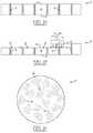
- FIG. 1 ashows a conventional semiconductor wafer 10 with base substrate material 12 , active surface 14 , and back surface 16 .
- Conductive vias 18are formed through semiconductor wafer 10 for electrical interconnect. Conductive vias 18 are created prior to wafer thinning and may be made of tungsten or other hard metal, sometimes with an oxide material between the conductive via and base substrate material 12 for isolation.
- FIG. 1 bshows a grinding operation with grinding wheel 20 removing a portion of base substrate material 12 from back surface 16 of semiconductor wafer 10 and reducing the thickness of the semiconductor wafer.
- Grinding wheel 20operates on a constant feed rate of the grinding wheel into the grinding surface. Grinding wheel 20 typically goes through some portion of base substrate material 12 before reaching conductive vias 18 .
- the grinding operationleaves particles 22 from base substrate material 12 , conductive vias 18 , and grinding wheel 20 , and other contaminants on the grinding surface. The particles and contaminants 22 become lodged between grinding wheel teeth 21 , and between grinding wheel 20 and base substrate material 12 .
- the grinding wheel rotation with the various particles and contaminants 22form surface cracks, gouges, and other damage 24 in final post-grinding surface 26 , as shown in FIG. 1 c .
- the tungsten conductive vias 18are brittle and break apart and become lodged between the grinding wheel and grinding surface, leaving the cracks, gouges, scratches, and other damage 24 in final post-grinding surface 26 .
- the damage to final surface 26may cause semiconductor wafer 10 to fail inspection.
- the cracks, gouges, and other damage 24 in final post-grinding surface 26may create stress concentration points which can lead to wafer and die breakage and reduce production yield.
- FIGS. 1 a -1 cillustrate a conventional semiconductor wafer grinding process leaving cracks, gouges, and other damage in final post-grinding surface
- FIGS. 2 a -2 cillustrate a semiconductor wafer with a plurality of semiconductor die separated by a saw street
- FIGS. 3 a -3 nillustrate a process of wafer thinning using a grinding phase and separation phase to reduce surface damage.
- semiconductor dierefers to both the singular and plural form of the words, and accordingly, can refer to both a single semiconductor device and multiple semiconductor devices.
- Front-end manufacturinginvolves the formation of a plurality of die on the surface of a semiconductor wafer.
- Each die on the wafermay contain active and passive electrical components and optical devices, which are electrically connected to form functional electrical circuits.
- Active electrical componentssuch as transistors and diodes, have the ability to control the flow of electrical current.
- Passive electrical componentssuch as capacitors, inductors, and resistors, create a relationship between voltage and current necessary to perform electrical circuit functions.
- the optical devicedetects and records an image by converting the variable attenuation of light waves or electromagnetic radiation into electric signals.
- Back-end manufacturingrefers to cutting or singulating the finished wafer into the individual semiconductor die and packaging the semiconductor die for structural support, electrical interconnect, and environmental isolation.
- the waferis singulated using plasma etching, laser cutting tool, or saw blade along non-functional regions of the wafer called saw streets or scribes.
- the individual semiconductor dieare mounted to a package substrate that includes pins or interconnect pads for interconnection with other system components. Interconnect pads formed over the semiconductor die are then connected to interconnect pads within the package.
- the electrical connectionscan be made with conductive layers, bumps, stud bumps, conductive paste, or wirebonds.
- An encapsulant or other molding materialis deposited over the package to provide physical support and electrical isolation.
- the finished packageis then inserted into an electrical system and the functionality of the semiconductor device is made available to the other system components.
- FIG. 2 ashows a semiconductor wafer 100 with a base substrate material 102 , such as silicon, germanium, aluminum phosphide, aluminum arsenide, gallium arsenide, gallium nitride, indium phosphide, silicon carbide, or other bulk semiconductor material.
- a plurality of semiconductor die 104is formed on wafer 100 separated by non-active saw street 106 , as described above. Saw street 106 provides singulation areas to separate semiconductor wafer 100 into individual semiconductor die 104 .
- semiconductor wafer 100has a width or diameter of 100-450 millimeters (mm) and thickness of 675-775 micrometers ( ⁇ m). In another embodiment, semiconductor wafer 100 has a width or diameter of 150-300 mm.
- FIG. 2 bshows a cross-sectional view of a portion of semiconductor wafer 100 .
- Each semiconductor die 104has a back surface 108 and an active surface or region 110 containing analog or digital circuits implemented as active devices, passive devices, conductive layers, and dielectric layers formed within the die and electrically interconnected according to the electrical design and function of the die.
- the circuitmay include one or more transistors, diodes, and other circuit elements formed within active surface or region 110 to implement analog circuits or digital circuits, such as digital signal processor (DSP), microcontrollers, ASIC, power conversion, standard logic, amplifiers, clock management, memory, interface circuits, and other signal processing circuit.
- DSPdigital signal processor
- Semiconductor die 104may also contain integrated passive devices (IPDs), such as inductors, capacitors, and resistors, for RF signal processing.
- Active surface 110may contain an image sensor area implemented as semiconductor charge-coupled devices (CCD) and active pixel sensors in complementary metal-oxide-semiconductor (CMOS) or N-type metal-oxide-semiconductor (NMOS) technologies.
- CCDsemiconductor charge-coupled devices
- CMOScomplementary metal-oxide-semiconductor
- NMOSN-type metal-oxide-semiconductor
- semiconductor die 104can be an optical lens, detector, vertical cavity surface emitting laser (VCSEL), waveguide, stacked die, electromagnetic (EM) filter, or multi-chip module.
- VCSELvertical cavity surface emitting laser
- EMelectromagnetic
- An electrically conductive layer 112is formed over active surface 110 using PVD, CVD, electrolytic plating, electroless plating process, evaporation, or other suitable metal deposition process.
- Conductive layer 112includes one or more layers of aluminum (Al), copper (Cu), tin (Sn), nickel (Ni), gold (Au), silver (Ag), tungsten (W), titanium (Ti), titanium tungsten (TiW), or other suitable electrically conductive material.
- Conductive layer 112operates as interconnect pads electrically connected to the circuits on active surface 110 .
- a plurality of viasis formed through semiconductor wafer 100 using mechanical drilling, laser drilling, or deep reactive ion etching (DRIE).
- the viasare filled with Al, Cu, Sn, Ni, Au, Ag, W, Ti, TiW, poly-silicon, or other suitable electrically conductive material using electrolytic plating, electroless plating process, or other suitable metal deposition process to form z-direction conductive through silicon vias (TSV) 114 embedded within semiconductor die 104 .
- TSVz-direction conductive through silicon vias
- Semiconductor wafer 100undergoes electrical testing and inspection as part of a quality control process.
- Manual visual inspection and automated optical systemsare used to perform inspections on semiconductor wafer 100 .
- Softwarecan be used in the automated optical analysis of semiconductor wafer 100 .
- Visual inspection methodsmay employ equipment such as a scanning electron microscope, high-intensity or ultra-violet light, metallurgical microscope, or optical microscope.
- Semiconductor wafer 100is inspected for structural characteristics including warpage, thickness variation, surface particulates, irregularities, cracks, delamination, contamination, and discoloration.
- the active and passive components within semiconductor die 104undergo testing at the wafer level for electrical performance and circuit function.
- Each semiconductor die 104is tested for functionality and electrical parameters, as shown in FIG. 2 c , using a test probe head 116 including a plurality of probes or test leads 118 , or other testing device.
- Probes 118are used to make electrical contact with nodes or conductive layer 112 on each semiconductor die 104 and provide electrical stimuli to interconnect pads 112 .
- Semiconductor die 104responds to the electrical stimuli, which is measured by computer test system 120 and compared to an expected response to test functionality of the semiconductor die.
- the electrical testsmay include circuit functionality, lead integrity, resistivity, continuity, reliability, junction depth, ESD, RF performance, drive current, threshold current, leakage current, and operational parameters specific to the component type.
- the inspection and electrical testing of semiconductor wafer 100enables semiconductor die 104 that pass to be designated as known good die for use in a semiconductor package.
- FIGS. 3 a -3 nillustrate a process of wafer thinning using a grinding phase and separation phase to reduce surface damage.
- FIG. 3 ashows an entire area of semiconductor wafer 100 with back surface 108 , active surface 110 , and conductive TSV 114 .
- Semiconductor die 104are present in active surface 110 , see FIGS. 2 a -2 c , but not labeled for purposes of the present explanation.
- Semiconductor wafer 100has a pre-grinding thickness T 1 of 675-775 ⁇ m.
- semiconductor wafer 100is inverted and mounted with active surface 110 oriented to backgrinding tape 130 .
- the entire back surface 108undergoes a first grinding operation with grinder or grinding wheel 132 rotating and semiconductor wafer 100 rotating to remove a portion of base substrate material 102 .
- grinding wheel 132is applied to base substrate material 102 at time t 1 and moves in a cyclic, spinning pattern. A small portion of the grinding surface is removed with each pass.
- the grinding phaseleaves particles 135 from base substrate material 102 , conductive TSV 114 , and grinding wheel 132 , and other contaminants on the grinding surface.
- the particles and contaminants 135become lodged between grinding wheel teeth 133 , and between grinding wheel 132 and the grinding surface.
- the grinding wheelmoves in the z-direction to physically separate the grinding wheel from base substrate material 102 .
- the downward movement of the grinding wheelcan be paused instead of reversed, to allow the rinse water to clear the particles.
- FIG. 3 dshows grinding wheel 132 lifting off base substrate material 102 at time t 2 during a lift-off or separation phase.
- grinding wheel 132is again applied to base substrate material 102 during another grinding phase at time t 3 .
- rinsing solution source 136continuously dispenses a rinsing solution or water 138 to the grinding surface to wash away particles and contaminants 135 .
- rinsing solution 138clears most if not substantially all particles and contaminants 135 from under grinding wheel 132 and between grinding wheel teeth 133 .
- the rotation of semiconductor wafer 100 and the volume of rinsing solution 138disperses particles and contaminants 135 from under grinding wheel 132 , between grinding teeth 133 , and from the grinding surface.
- Grinding wheel 132may lift off surface 134 at time t 2 , stop rotation, and reverse direction of rotation between time t 2 and time t 3 . Grinding wheel 132 may pause in vertical movement during the separation phase, or pause in rotational movement during the grinding phase and/or separation phase.
- the grinding phase period t 1 -t 2 and separation phase period t 2 -t 3repeat during the first backgrinding operation until the desired thickness of semiconductor wafer 100 is achieved.
- the duration of grinding phase period t 1 -t 2is 5-30 seconds, and the duration of separation phase period t 2 -t 3 is 3-10 seconds.
- grinding wheel 132lifts off or moves 3-10 ⁇ m in the z-direction away from base substrate material 102 , or a sufficient height to clear most if not substantially all particles and contaminants 135 from grinding wheel teeth 133 .
- Rinsing solution 138washes away particles and contaminants 135 during the separation phase period t 2 -t 3 , as well as during the grinding phase period t 1 -t 2 .
- rinsing solution 138is applied in pulses to wash away particles and contaminants 135 .
- Rinsing solution source 136may swivel, rotate, or move about in a pattern over the grinding surface for an even and thorough distribution of rinsing solution 138 .
- the final surface 134is relatively free of the cracks, gouges, and other damage, as noted in the background.
- the repeating grinding phase period t 1 -t 2 and separation phase period t 2 -t 3may be practiced during the entire grinding operation, when grinding conductive TSVs 114 , or during the final grinding stages. Grinding wheel 132 can be designed with a slower wheel wear rate.
- Semiconductor wafer 100has a post-grinding thickness T 2 of about 355 ⁇ m between active surface 110 and final post-grinding surface 134 .
- grinding wheel 132may stop rotation, slow down the rotation, or spin slower than normal rate after the grinding phase at time t 2 , while the grinding wheel remains on surface 134 .
- Rinsing solution source 136continuously dispenses a rinsing solution or water 138 to the grinding surface to wash away particles and contaminants 135 .
- grinding wheel 132re-starts rotation in the previous direction or reverses direction of rotation. The grinding phase and stop phase repeat during the first backgrinding operation until the desired thickness of semiconductor wafer 100 is achieved.
- a second grinding operationis applied to surface 134 with grinder or grinding wheel 140 rotating and semiconductor wafer 100 rotating to remove a portion of base substrate material 102 .
- Grinding wheel 140moves in a cyclic, spinning pattern across an interior region or wafer grinding area 142 of semiconductor wafer 100 . A small portion of the grinding surface is removed with each pass. Grinding wheel 140 is controlled to leave edge support ring 146 of base substrate material 102 around a perimeter of semiconductor wafer 100 for structural support.
- grinder or grinding wheel 140is applied to base substrate material 102 at time t 1 , as shown in FIG. 3 f
- the grinding phaseleaves particles 145 from base substrate material 102 , conductive TSV 114 , and grinding wheel 140 , and other contaminants on the grinding surface.
- the particles and contaminants 145become lodged between grinding wheel teeth 141 , and between grinding wheel 140 and the grinding surface.
- the grinding wheelmoves in the z-direction to physically separate the grinding wheel from base substrate material 102 .
- FIG. 3 gshows grinding wheel 140 lifting off base substrate material 102 at time t 2 during a lift-off or separation phase.
- grinding wheel 140is again applied to base substrate material 102 during another grinding phase at time t 3 .
- rinsing solution source 147continuously dispenses a rinsing solution or water 148 to the grinding surface to wash away particles and contaminants 145 .
- rinsing solution 148clears most if not substantially all particles and contaminants 145 from under grinding wheel 140 and between grinding wheel teeth 141 .
- the rotation of semiconductor wafer 100 and the volume of rinsing solution 148disperses particles and contaminants 145 from under grinding wheel 140 , between grinding teeth 141 , and from the grinding surface.
- Grinding wheel 140may lift off surface 144 at time t 2 , stop rotation, and reverse direction of rotation between time t 2 and time t 3 . Grinding wheel 140 may pause in vertical movement during the separation phase, or pause in rotational movement during the grinding phase and/or separation phase.
- the grinding phase period t 1 -t 2 and separation phase period t 2 -t 3repeat during the second backgrinding operation until the desired thickness of semiconductor wafer 100 is achieved.
- the duration of grinding phase period t 1 -t 2is 5-30 seconds, and the duration of separation phase period t 2 -t 3 is 3-10 seconds.
- grinding wheel 140lifts off or moves 3-10 ⁇ m in the z-direction away from base substrate material 102 , or a sufficient height to clear most if not substantially all particles and contaminants 145 from grinding wheel teeth 141 .
- Rinsing solution 148washes away particles and contaminants 145 during the separation phase period t 2 -t 3 , as well as during the grinding phase period t 1 -t 2 .
- rinsing solution 148is applied in pulses to wash away particles and contaminants 145 .
- Rinsing solution source 147may swivel, rotate, or move about in a pattern over the grinding surface for an even and thorough distribution of rinsing solution 158 .
- the final surface 144is relatively free of the cracks, gouges, and other damage, as noted in the background.
- the repeating grinding phase period t 1 -t 2 and separation phase period t 2 -t 3may be practiced during the entire grinding operation, when grinding conductive TSVs 114 , or during the final grinding stages. Grinding wheel 140 can be designed with a slower wheel wear rate.
- the post-grinding thickness T 3 of semiconductor wafer 100is 75 ⁇ m or less. In another embodiment, the post-grinding thickness T 3 of semiconductor wafer 100 is 10-50 ⁇ m.
- grinding wheel 140may stop rotation after the grinding phase at time t 2 , while the grinding wheel remains on surface 134 .
- Rinsing solution source 147continuously dispenses a rinsing solution or water 148 to the grinding surface to wash away particles and contaminants 145 .
- grinding wheel 140re-starts rotation in the previous direction or reverses direction of rotation. The grinding phase and stop phase repeat during the first backgrinding operation until the desired thickness of semiconductor wafer 100 is achieved.
- FIG. 3 ishows a top view of grinding wheel 140 removing a portion of surface 134 of semiconductor wafer 100 to reduce the thickness of the semiconductor wafer, and correspondingly semiconductor die 104 , in grinding area 142 , while leaving edge support ring 146 of base substrate material 102 around a perimeter of the semiconductor wafer.
- Edge support ring 146has a width W 146 is 3.0 mm ⁇ 0.3 mm from inner wall 154 to outer edge 156 of semiconductor wafer 100 .
- the height of edge support ring 146is the first post-grinding thickness T 2 , which is greater than the second post-grinding thickness T 3 of semiconductor wafer 100 , to maintain structural integrity of the thinner semiconductor wafer.
- a post-grinding stress relief etchis used to remove or reduce the damage in surface 144 of base substrate material 102 caused by the grinding process.
- Surface 144 of semiconductor wafer 100is cleaned with a rinsing solution.
- An electrically conductive layer 166is formed over surface 144 using PVD, CVD, electrolytic plating, electroless plating process, evaporation, or other suitable metal deposition process.
- Conductive layer 166includes one or more layers of Al, Cu, Sn, Ni, Au, Ag, Ti, TiW, or other suitable electrically conductive material.
- Conductive layer 166provides back-side electrical interconnect for semiconductor die 104 .
- Conductive layer 166is patterned into electrically common or electrically isolated portions according to the function of semiconductor die 104 .
- Backgrinding tape 130is removed by exposing the tape to ultraviolet (UV) light and peeling off.
- UVultraviolet
- semiconductor wafer 100is mounted with active surface 110 oriented to tape portion 170 of film frame 172 .
- edge support ring 146is removed to be planar with or just above (10-13 ⁇ m) conductive layer 172 or surface 144 .
- semiconductor wafer 100is removed from film frame 172 , inverted, and mounted with conductive layer 166 on surface 144 oriented to tape portion 180 of film frame 182 .
- semiconductor wafer 100is singulated through saw streets 106 using a saw blade or laser cutting tool 186 or plasma etch into individual semiconductor die 104 .
Landscapes
- Engineering & Computer Science (AREA)
- Manufacturing & Machinery (AREA)
- Power Engineering (AREA)
- Microelectronics & Electronic Packaging (AREA)
- Computer Hardware Design (AREA)
- Condensed Matter Physics & Semiconductors (AREA)
- General Physics & Mathematics (AREA)
- Physics & Mathematics (AREA)
- Mechanical Engineering (AREA)
- Chemical & Material Sciences (AREA)
- Inorganic Chemistry (AREA)
- Ceramic Engineering (AREA)
- Mechanical Treatment Of Semiconductor (AREA)
Abstract
Description
Claims (12)
Priority Applications (3)
| Application Number | Priority Date | Filing Date | Title |
|---|---|---|---|
| US16/126,717US10998182B2 (en) | 2016-08-02 | 2018-09-10 | Semiconductor wafer and method of wafer thinning |
| US17/306,396US12154783B2 (en) | 2016-08-02 | 2021-05-03 | Semiconductor wafer and method of wafer thinning |
| US18/940,068US20250062114A1 (en) | 2016-08-02 | 2024-11-07 | Semiconductor wafer and method of wafer thinning |
Applications Claiming Priority (2)
| Application Number | Priority Date | Filing Date | Title |
|---|---|---|---|
| US15/226,362US10096460B2 (en) | 2016-08-02 | 2016-08-02 | Semiconductor wafer and method of wafer thinning using grinding phase and separation phase |
| US16/126,717US10998182B2 (en) | 2016-08-02 | 2018-09-10 | Semiconductor wafer and method of wafer thinning |
Related Parent Applications (1)
| Application Number | Title | Priority Date | Filing Date |
|---|---|---|---|
| US15/226,362ContinuationUS10096460B2 (en) | 2016-08-02 | 2016-08-02 | Semiconductor wafer and method of wafer thinning using grinding phase and separation phase |
Related Child Applications (1)
| Application Number | Title | Priority Date | Filing Date |
|---|---|---|---|
| US17/306,396ContinuationUS12154783B2 (en) | 2016-08-02 | 2021-05-03 | Semiconductor wafer and method of wafer thinning |
Publications (2)
| Publication Number | Publication Date |
|---|---|
| US20190006169A1 US20190006169A1 (en) | 2019-01-03 |
| US10998182B2true US10998182B2 (en) | 2021-05-04 |
Family
ID=61069312
Family Applications (4)
| Application Number | Title | Priority Date | Filing Date |
|---|---|---|---|
| US15/226,362Active2036-12-07US10096460B2 (en) | 2016-08-02 | 2016-08-02 | Semiconductor wafer and method of wafer thinning using grinding phase and separation phase |
| US16/126,717Active2037-06-14US10998182B2 (en) | 2016-08-02 | 2018-09-10 | Semiconductor wafer and method of wafer thinning |
| US17/306,396Active2038-06-17US12154783B2 (en) | 2016-08-02 | 2021-05-03 | Semiconductor wafer and method of wafer thinning |
| US18/940,068PendingUS20250062114A1 (en) | 2016-08-02 | 2024-11-07 | Semiconductor wafer and method of wafer thinning |
Family Applications Before (1)
| Application Number | Title | Priority Date | Filing Date |
|---|---|---|---|
| US15/226,362Active2036-12-07US10096460B2 (en) | 2016-08-02 | 2016-08-02 | Semiconductor wafer and method of wafer thinning using grinding phase and separation phase |
Family Applications After (2)
| Application Number | Title | Priority Date | Filing Date |
|---|---|---|---|
| US17/306,396Active2038-06-17US12154783B2 (en) | 2016-08-02 | 2021-05-03 | Semiconductor wafer and method of wafer thinning |
| US18/940,068PendingUS20250062114A1 (en) | 2016-08-02 | 2024-11-07 | Semiconductor wafer and method of wafer thinning |
Country Status (2)
| Country | Link |
|---|---|
| US (4) | US10096460B2 (en) |
| CN (2) | CN107680936B (en) |
Families Citing this family (10)
| Publication number | Priority date | Publication date | Assignee | Title |
|---|---|---|---|---|
| US10096460B2 (en)* | 2016-08-02 | 2018-10-09 | Semiconductor Components Industries, Llc | Semiconductor wafer and method of wafer thinning using grinding phase and separation phase |
| US10204873B2 (en)* | 2017-05-08 | 2019-02-12 | Infineon Technologies Americas Corp. | Breakable substrate for semiconductor die |
| JP7115850B2 (en)* | 2017-12-28 | 2022-08-09 | 株式会社ディスコ | Workpiece processing method and processing apparatus |
| CN108705421A (en)* | 2018-08-21 | 2018-10-26 | 德清明宇电子科技有限公司 | A kind of E-type magnetic core grinding device |
| US20200321236A1 (en)* | 2019-04-02 | 2020-10-08 | Semiconductor Components Industries, Llc | Edge ring removal methods |
| US10727216B1 (en) | 2019-05-10 | 2020-07-28 | Sandisk Technologies Llc | Method for removing a bulk substrate from a bonded assembly of wafers |
| JP7461118B2 (en)* | 2019-08-19 | 2024-04-03 | 株式会社ディスコ | Wafer processing method |
| US11063008B2 (en)* | 2019-09-16 | 2021-07-13 | Taiwan Semiconductor Manufacturing Company, Ltd. | Semiconductor structure and manufacturing method thereof |
| JP7346374B2 (en)* | 2020-09-23 | 2023-09-19 | 株式会社東芝 | Method for manufacturing semiconductor substrates and semiconductor devices |
| FR3139409B1 (en)* | 2022-09-01 | 2024-08-23 | Soitec Silicon On Insulator | Process for preparing the front face of a polycrystalline silicon carbide plate |
Citations (66)
| Publication number | Priority date | Publication date | Assignee | Title |
|---|---|---|---|---|
| US1933373A (en)* | 1928-09-07 | 1933-10-31 | Norton Co | Grinding and lapping machine |
| US3948001A (en)* | 1973-10-05 | 1976-04-06 | Agency Of Industrial Science & Technology | Curved surface grinding machine |
| US4184893A (en)* | 1976-07-13 | 1980-01-22 | E. I. Du Pont De Nemours And Company | Pulsed rinse of particulate beds |
| USRE30537E (en)* | 1979-08-20 | 1981-03-03 | Hobart Corporation | Method for rinsing and chemically sanitizing food ware items |
| US4276672A (en)* | 1977-11-07 | 1981-07-07 | Teague Jr Walter D | Power toothbrush or the like with orbital brush action |
| USRE33849E (en)* | 1988-09-09 | 1992-03-17 | Innovative Control Systems, Inc. | Computerized car wash controller system |
| US5276999A (en)* | 1990-06-09 | 1994-01-11 | Bando Kiko Co., Ltd. | Machine for polishing surface of glass plate |
| US5522965A (en) | 1994-12-12 | 1996-06-04 | Texas Instruments Incorporated | Compact system and method for chemical-mechanical polishing utilizing energy coupled to the polishing pad/water interface |
| US5531017A (en)* | 1994-02-14 | 1996-07-02 | International Business Machines Corporation | Thin film magnetic head fabrication method |
| US5545076A (en) | 1994-05-16 | 1996-08-13 | Samsung Electronics Co., Ltd. | Apparatus for gringing a semiconductor wafer while removing dust therefrom |
| US5741173A (en)* | 1995-12-15 | 1998-04-21 | Wacker Siltronic Gesellschaft Fur Halbleitermaterialien Ag | Method and apparatus for machining semiconductor material |
| US5816895A (en)* | 1997-01-17 | 1998-10-06 | Tokyo Seimitsu Co., Ltd. | Surface grinding method and apparatus |
| US5868866A (en) | 1995-03-03 | 1999-02-09 | Ebara Corporation | Method of and apparatus for cleaning workpiece |
| US5957757A (en) | 1997-10-30 | 1999-09-28 | Lsi Logic Corporation | Conditioning CMP polishing pad using a high pressure fluid |
| US6012968A (en)* | 1998-07-31 | 2000-01-11 | International Business Machines Corporation | Apparatus for and method of conditioning chemical mechanical polishing pad during workpiece polishing cycle |
| US6132295A (en)* | 1999-08-12 | 2000-10-17 | Applied Materials, Inc. | Apparatus and method for grinding a semiconductor wafer surface |
| US6138690A (en) | 1997-04-28 | 2000-10-31 | Mitsubishi Denki Kabushiki Kaisha | Method and an apparatus for the wet treatment of a semiconductor wafer |
| US6152809A (en)* | 1998-09-03 | 2000-11-28 | Yenawine; Peter W. | Method and apparatus for cold-end processing full-lead crystal |
| US6227956B1 (en) | 1999-10-28 | 2001-05-08 | Strasbaugh | Pad quick release device for chemical mechanical polishing |
| US6276997B1 (en) | 1998-12-23 | 2001-08-21 | Shinhwa Li | Use of chemical mechanical polishing and/or poly-vinyl-acetate scrubbing to restore quality of used semiconductor wafers |
| US20010019934A1 (en)* | 1997-03-21 | 2001-09-06 | Matsuomi Nishimura | Polishing apparatus including holder and polishing head with rotational axis of polishing head offset from rotational axis of holder and method of using |
| US6296547B1 (en)* | 1999-11-16 | 2001-10-02 | Litton Systems, Inc. | Method and system for manufacturing a photocathode |
| US6319105B1 (en) | 1998-06-09 | 2001-11-20 | Ebara Corporation | Polishing apparatus |
| US6332833B1 (en) | 1996-08-08 | 2001-12-25 | Naoetsu Electronics Company | Method for fabricating silicon semiconductor discrete wafer |
| US6340326B1 (en) | 2000-01-28 | 2002-01-22 | Lam Research Corporation | System and method for controlled polishing and planarization of semiconductor wafers |
| US20020022445A1 (en) | 2000-08-09 | 2002-02-21 | Hiroshi Sotozaki | Substrate cleaning apparatus |
| US6361647B1 (en)* | 1999-09-28 | 2002-03-26 | Stras Baugh | Method and apparatus for chemical mechanical polishing |
| US20020061647A1 (en) | 1996-12-20 | 2002-05-23 | Tomokazu Kawamoto | Method for manufacturing a semiconductor device including treatment of substrate and apparatus for treatment of substrate |
| US6402588B1 (en)* | 1998-04-27 | 2002-06-11 | Ebara Corporation | Polishing apparatus |
| US20020081954A1 (en)* | 2000-12-27 | 2002-06-27 | Takashi Mori | Grinding machine |
| US6439962B1 (en) | 1998-01-30 | 2002-08-27 | Ebara Corporation | Cleaning apparatus |
| US6443816B2 (en) | 2000-02-24 | 2002-09-03 | Ebara Corporation | Method and apparatus for cleaning polishing surface of polisher |
| US6547651B1 (en) | 1999-11-10 | 2003-04-15 | Strasbaugh | Subaperture chemical mechanical planarization with polishing pad conditioning |
| US6572444B1 (en)* | 2000-08-31 | 2003-06-03 | Micron Technology, Inc. | Apparatus and methods of automated wafer-grinding using grinding surface position monitoring |
| US20040029497A1 (en)* | 2000-11-28 | 2004-02-12 | Peter Baeumler | Method and device for producing molds for toothed belts |
| US20040092210A1 (en)* | 2002-11-07 | 2004-05-13 | Taiwan Semiconductor Manufacturing Company | Method to reduce defect/slurry residue for copper CMP |
| US20040198196A1 (en)* | 2003-04-04 | 2004-10-07 | Strasbaugh | Grinding apparatus and method |
| US7089081B2 (en)* | 2003-01-31 | 2006-08-08 | 3M Innovative Properties Company | Modeling an abrasive process to achieve controlled material removal |
| US20070066184A1 (en) | 2003-10-16 | 2007-03-22 | Lintec Corporation | Surface-protecting sheet and semiconductor wafer lapping method |
| US20080214094A1 (en) | 2007-02-15 | 2008-09-04 | Takeo Katoh | Method for manufacturing silicon wafer |
| US20080242106A1 (en)* | 2007-03-29 | 2008-10-02 | Anuj Sarveshwar Narain | CHEMICAL MECHANICAL POLISHING METHOD AND APPARATUS FOR REDUCING MATERIAL RE-DEPOSITION DUE TO pH TRANSITIONS |
| US7572172B2 (en) | 2005-09-15 | 2009-08-11 | Fujitsu Microelectronics Limited | Polishing machine, workpiece supporting table pad, polishing method and manufacturing method of semiconductor device |
| US20090247056A1 (en) | 2008-03-31 | 2009-10-01 | Disco Corporation | Grinding method for wafer having crystal orientation |
| US20100078046A1 (en)* | 2008-09-30 | 2010-04-01 | Mohamed Emam Labib | Apparatus and method for cleaning passageways such as endoscope channels using flow of liquid and gas |
| US20100248597A1 (en) | 2009-03-27 | 2010-09-30 | Kentaro Sakata | Equipment and method for cleaning polishing cloth |
| US20110014852A1 (en)* | 2007-12-19 | 2011-01-20 | Nxp B.V. | Pick and place tool grinding |
| US7910157B2 (en) | 2005-12-27 | 2011-03-22 | Tokyo Electron Limited | Substrate processing method and program |
| US8147617B2 (en) | 2004-06-04 | 2012-04-03 | Tokyo Electron Limited | Substrate cleaning method and computer readable storage medium |
| US8152597B2 (en)* | 2008-03-27 | 2012-04-10 | Tokyo Seimitsu Co., Ltd. | Wafer grinding method and wafer grinding machine |
| US20120231705A1 (en) | 2011-03-11 | 2012-09-13 | Fuji Electric Co., Ltd. | Method and apparatus for manufacturing a semiconductor device |
| US20130023188A1 (en) | 2011-07-21 | 2013-01-24 | Taiwan Semiconductor Manufacturing Company, Ltd. | Apparatus for Wafer Grinding |
| US20130023186A1 (en) | 2011-07-19 | 2013-01-24 | Yasuyuki Motoshima | Method and apparatus for polishing a substrate |
| US20130052812A1 (en) | 2011-08-26 | 2013-02-28 | Mitsubishi Electric Corporation | Method of manufacturing semiconductor device |
| US8562392B2 (en) | 2009-04-27 | 2013-10-22 | Renesas Electronics Corporation | Polishing apparatus and polishing method |
| US20140106079A1 (en)* | 2012-10-11 | 2014-04-17 | Finishing Brands Holdings Inc. | System and Method for Producing a Structure with an Electrostatic Spray |
| US20140323017A1 (en) | 2013-04-24 | 2014-10-30 | Applied Materials, Inc. | Methods and apparatus using energized fluids to clean chemical mechanical planarization polishing pads |
| US20150273657A1 (en)* | 2014-03-27 | 2015-10-01 | Ebara Corporation | Elastic membrane, substrate holding apparatus, and polishing apparatus |
| US20150290767A1 (en) | 2014-04-10 | 2015-10-15 | Ebara Corporation | Substrate processing apparatus |
| US20160023323A1 (en)* | 2014-07-25 | 2016-01-28 | Samsung Electronics Co., Ltd. | Carrier head and chemical mechanical polishing apparatus |
| US20160064230A1 (en) | 2014-08-26 | 2016-03-03 | Disco Corporation | Wafer processing method |
| US20160181086A1 (en)* | 2014-12-19 | 2016-06-23 | Applied Materials, Inc. | Systems and methods for rinsing and drying substrates |
| US20160194538A1 (en)* | 2013-08-07 | 2016-07-07 | Konica Minolta, Inc. | Polishing Material Particles, Method For Producing Polishing Material, And Polishing Processing Method |
| US9700988B2 (en) | 2014-08-26 | 2017-07-11 | Ebara Corporation | Substrate processing apparatus |
| US20170232569A1 (en)* | 2016-02-12 | 2017-08-17 | Darex, Llc | Powered tool sharpener with multi-speed abrasive |
| US20180021911A1 (en)* | 2016-07-22 | 2018-01-25 | Disco Corporation | Grinding apparatus |
| US10096460B2 (en)* | 2016-08-02 | 2018-10-09 | Semiconductor Components Industries, Llc | Semiconductor wafer and method of wafer thinning using grinding phase and separation phase |
Family Cites Families (7)
| Publication number | Priority date | Publication date | Assignee | Title |
|---|---|---|---|---|
| JP2968784B1 (en)* | 1998-06-19 | 1999-11-02 | 日本電気株式会社 | Polishing method and apparatus used therefor |
| US6240942B1 (en)* | 1999-05-13 | 2001-06-05 | Micron Technology, Inc. | Method for conserving a resource by flow interruption |
| JP4030247B2 (en)* | 1999-05-17 | 2008-01-09 | 株式会社荏原製作所 | Dressing device and polishing device |
| JP3990073B2 (en)* | 1999-06-17 | 2007-10-10 | 株式会社荏原製作所 | Substrate cleaning apparatus and substrate cleaning method |
| JP5268599B2 (en)* | 2008-12-03 | 2013-08-21 | 株式会社ディスコ | Grinding apparatus and grinding method |
| CN102157368A (en)* | 2010-02-11 | 2011-08-17 | 中芯国际集成电路制造(上海)有限公司 | Method for removing residues after chemical mechanical polishing |
| US9539699B2 (en)* | 2014-08-28 | 2017-01-10 | Ebara Corporation | Polishing method |
- 2016
- 2016-08-02USUS15/226,362patent/US10096460B2/enactiveActive
- 2017
- 2017-08-02CNCN201710649147.7Apatent/CN107680936B/enactiveActive
- 2017-08-02CNCN202311575435.4Apatent/CN117438288A/enactivePending
- 2018
- 2018-09-10USUS16/126,717patent/US10998182B2/enactiveActive
- 2021
- 2021-05-03USUS17/306,396patent/US12154783B2/enactiveActive
- 2024
- 2024-11-07USUS18/940,068patent/US20250062114A1/enactivePending
Patent Citations (66)
| Publication number | Priority date | Publication date | Assignee | Title |
|---|---|---|---|---|
| US1933373A (en)* | 1928-09-07 | 1933-10-31 | Norton Co | Grinding and lapping machine |
| US3948001A (en)* | 1973-10-05 | 1976-04-06 | Agency Of Industrial Science & Technology | Curved surface grinding machine |
| US4184893A (en)* | 1976-07-13 | 1980-01-22 | E. I. Du Pont De Nemours And Company | Pulsed rinse of particulate beds |
| US4276672A (en)* | 1977-11-07 | 1981-07-07 | Teague Jr Walter D | Power toothbrush or the like with orbital brush action |
| USRE30537E (en)* | 1979-08-20 | 1981-03-03 | Hobart Corporation | Method for rinsing and chemically sanitizing food ware items |
| USRE33849E (en)* | 1988-09-09 | 1992-03-17 | Innovative Control Systems, Inc. | Computerized car wash controller system |
| US5276999A (en)* | 1990-06-09 | 1994-01-11 | Bando Kiko Co., Ltd. | Machine for polishing surface of glass plate |
| US5531017A (en)* | 1994-02-14 | 1996-07-02 | International Business Machines Corporation | Thin film magnetic head fabrication method |
| US5545076A (en) | 1994-05-16 | 1996-08-13 | Samsung Electronics Co., Ltd. | Apparatus for gringing a semiconductor wafer while removing dust therefrom |
| US5522965A (en) | 1994-12-12 | 1996-06-04 | Texas Instruments Incorporated | Compact system and method for chemical-mechanical polishing utilizing energy coupled to the polishing pad/water interface |
| US5868866A (en) | 1995-03-03 | 1999-02-09 | Ebara Corporation | Method of and apparatus for cleaning workpiece |
| US5741173A (en)* | 1995-12-15 | 1998-04-21 | Wacker Siltronic Gesellschaft Fur Halbleitermaterialien Ag | Method and apparatus for machining semiconductor material |
| US6332833B1 (en) | 1996-08-08 | 2001-12-25 | Naoetsu Electronics Company | Method for fabricating silicon semiconductor discrete wafer |
| US20020061647A1 (en) | 1996-12-20 | 2002-05-23 | Tomokazu Kawamoto | Method for manufacturing a semiconductor device including treatment of substrate and apparatus for treatment of substrate |
| US5816895A (en)* | 1997-01-17 | 1998-10-06 | Tokyo Seimitsu Co., Ltd. | Surface grinding method and apparatus |
| US20010019934A1 (en)* | 1997-03-21 | 2001-09-06 | Matsuomi Nishimura | Polishing apparatus including holder and polishing head with rotational axis of polishing head offset from rotational axis of holder and method of using |
| US6138690A (en) | 1997-04-28 | 2000-10-31 | Mitsubishi Denki Kabushiki Kaisha | Method and an apparatus for the wet treatment of a semiconductor wafer |
| US5957757A (en) | 1997-10-30 | 1999-09-28 | Lsi Logic Corporation | Conditioning CMP polishing pad using a high pressure fluid |
| US6439962B1 (en) | 1998-01-30 | 2002-08-27 | Ebara Corporation | Cleaning apparatus |
| US6402588B1 (en)* | 1998-04-27 | 2002-06-11 | Ebara Corporation | Polishing apparatus |
| US6319105B1 (en) | 1998-06-09 | 2001-11-20 | Ebara Corporation | Polishing apparatus |
| US6012968A (en)* | 1998-07-31 | 2000-01-11 | International Business Machines Corporation | Apparatus for and method of conditioning chemical mechanical polishing pad during workpiece polishing cycle |
| US6152809A (en)* | 1998-09-03 | 2000-11-28 | Yenawine; Peter W. | Method and apparatus for cold-end processing full-lead crystal |
| US6276997B1 (en) | 1998-12-23 | 2001-08-21 | Shinhwa Li | Use of chemical mechanical polishing and/or poly-vinyl-acetate scrubbing to restore quality of used semiconductor wafers |
| US6132295A (en)* | 1999-08-12 | 2000-10-17 | Applied Materials, Inc. | Apparatus and method for grinding a semiconductor wafer surface |
| US6361647B1 (en)* | 1999-09-28 | 2002-03-26 | Stras Baugh | Method and apparatus for chemical mechanical polishing |
| US6227956B1 (en) | 1999-10-28 | 2001-05-08 | Strasbaugh | Pad quick release device for chemical mechanical polishing |
| US6547651B1 (en) | 1999-11-10 | 2003-04-15 | Strasbaugh | Subaperture chemical mechanical planarization with polishing pad conditioning |
| US6296547B1 (en)* | 1999-11-16 | 2001-10-02 | Litton Systems, Inc. | Method and system for manufacturing a photocathode |
| US6340326B1 (en) | 2000-01-28 | 2002-01-22 | Lam Research Corporation | System and method for controlled polishing and planarization of semiconductor wafers |
| US6443816B2 (en) | 2000-02-24 | 2002-09-03 | Ebara Corporation | Method and apparatus for cleaning polishing surface of polisher |
| US20020022445A1 (en) | 2000-08-09 | 2002-02-21 | Hiroshi Sotozaki | Substrate cleaning apparatus |
| US6572444B1 (en)* | 2000-08-31 | 2003-06-03 | Micron Technology, Inc. | Apparatus and methods of automated wafer-grinding using grinding surface position monitoring |
| US20040029497A1 (en)* | 2000-11-28 | 2004-02-12 | Peter Baeumler | Method and device for producing molds for toothed belts |
| US20020081954A1 (en)* | 2000-12-27 | 2002-06-27 | Takashi Mori | Grinding machine |
| US20040092210A1 (en)* | 2002-11-07 | 2004-05-13 | Taiwan Semiconductor Manufacturing Company | Method to reduce defect/slurry residue for copper CMP |
| US7089081B2 (en)* | 2003-01-31 | 2006-08-08 | 3M Innovative Properties Company | Modeling an abrasive process to achieve controlled material removal |
| US20040198196A1 (en)* | 2003-04-04 | 2004-10-07 | Strasbaugh | Grinding apparatus and method |
| US20070066184A1 (en) | 2003-10-16 | 2007-03-22 | Lintec Corporation | Surface-protecting sheet and semiconductor wafer lapping method |
| US8147617B2 (en) | 2004-06-04 | 2012-04-03 | Tokyo Electron Limited | Substrate cleaning method and computer readable storage medium |
| US7572172B2 (en) | 2005-09-15 | 2009-08-11 | Fujitsu Microelectronics Limited | Polishing machine, workpiece supporting table pad, polishing method and manufacturing method of semiconductor device |
| US7910157B2 (en) | 2005-12-27 | 2011-03-22 | Tokyo Electron Limited | Substrate processing method and program |
| US20080214094A1 (en) | 2007-02-15 | 2008-09-04 | Takeo Katoh | Method for manufacturing silicon wafer |
| US20080242106A1 (en)* | 2007-03-29 | 2008-10-02 | Anuj Sarveshwar Narain | CHEMICAL MECHANICAL POLISHING METHOD AND APPARATUS FOR REDUCING MATERIAL RE-DEPOSITION DUE TO pH TRANSITIONS |
| US20110014852A1 (en)* | 2007-12-19 | 2011-01-20 | Nxp B.V. | Pick and place tool grinding |
| US8152597B2 (en)* | 2008-03-27 | 2012-04-10 | Tokyo Seimitsu Co., Ltd. | Wafer grinding method and wafer grinding machine |
| US20090247056A1 (en) | 2008-03-31 | 2009-10-01 | Disco Corporation | Grinding method for wafer having crystal orientation |
| US20100078046A1 (en)* | 2008-09-30 | 2010-04-01 | Mohamed Emam Labib | Apparatus and method for cleaning passageways such as endoscope channels using flow of liquid and gas |
| US20100248597A1 (en) | 2009-03-27 | 2010-09-30 | Kentaro Sakata | Equipment and method for cleaning polishing cloth |
| US8562392B2 (en) | 2009-04-27 | 2013-10-22 | Renesas Electronics Corporation | Polishing apparatus and polishing method |
| US20120231705A1 (en) | 2011-03-11 | 2012-09-13 | Fuji Electric Co., Ltd. | Method and apparatus for manufacturing a semiconductor device |
| US20130023186A1 (en) | 2011-07-19 | 2013-01-24 | Yasuyuki Motoshima | Method and apparatus for polishing a substrate |
| US20130023188A1 (en) | 2011-07-21 | 2013-01-24 | Taiwan Semiconductor Manufacturing Company, Ltd. | Apparatus for Wafer Grinding |
| US20130052812A1 (en) | 2011-08-26 | 2013-02-28 | Mitsubishi Electric Corporation | Method of manufacturing semiconductor device |
| US20140106079A1 (en)* | 2012-10-11 | 2014-04-17 | Finishing Brands Holdings Inc. | System and Method for Producing a Structure with an Electrostatic Spray |
| US20140323017A1 (en) | 2013-04-24 | 2014-10-30 | Applied Materials, Inc. | Methods and apparatus using energized fluids to clean chemical mechanical planarization polishing pads |
| US20160194538A1 (en)* | 2013-08-07 | 2016-07-07 | Konica Minolta, Inc. | Polishing Material Particles, Method For Producing Polishing Material, And Polishing Processing Method |
| US20150273657A1 (en)* | 2014-03-27 | 2015-10-01 | Ebara Corporation | Elastic membrane, substrate holding apparatus, and polishing apparatus |
| US20150290767A1 (en) | 2014-04-10 | 2015-10-15 | Ebara Corporation | Substrate processing apparatus |
| US20160023323A1 (en)* | 2014-07-25 | 2016-01-28 | Samsung Electronics Co., Ltd. | Carrier head and chemical mechanical polishing apparatus |
| US20160064230A1 (en) | 2014-08-26 | 2016-03-03 | Disco Corporation | Wafer processing method |
| US9700988B2 (en) | 2014-08-26 | 2017-07-11 | Ebara Corporation | Substrate processing apparatus |
| US20160181086A1 (en)* | 2014-12-19 | 2016-06-23 | Applied Materials, Inc. | Systems and methods for rinsing and drying substrates |
| US20170232569A1 (en)* | 2016-02-12 | 2017-08-17 | Darex, Llc | Powered tool sharpener with multi-speed abrasive |
| US20180021911A1 (en)* | 2016-07-22 | 2018-01-25 | Disco Corporation | Grinding apparatus |
| US10096460B2 (en)* | 2016-08-02 | 2018-10-09 | Semiconductor Components Industries, Llc | Semiconductor wafer and method of wafer thinning using grinding phase and separation phase |
Also Published As
| Publication number | Publication date |
|---|---|
| US20190006169A1 (en) | 2019-01-03 |
| CN117438288A (en) | 2024-01-23 |
| US20210257208A1 (en) | 2021-08-19 |
| US20180040469A1 (en) | 2018-02-08 |
| CN107680936A (en) | 2018-02-09 |
| CN107680936B (en) | 2023-11-17 |
| US12154783B2 (en) | 2024-11-26 |
| US20250062114A1 (en) | 2025-02-20 |
| US10096460B2 (en) | 2018-10-09 |
Similar Documents
| Publication | Publication Date | Title |
|---|---|---|
| US12154783B2 (en) | Semiconductor wafer and method of wafer thinning | |
| US11018092B2 (en) | Thinned semiconductor wafer | |
| US10903154B2 (en) | Semiconductor device and method of forming cantilevered protrusion on a semiconductor die | |
| US10685891B2 (en) | Semicoductor wafer and method of backside probe testing through opening in film frame | |
| US12154877B2 (en) | Semiconductor wafer and method of ball drop on thin wafer with edge support ring | |
| US20150214077A1 (en) | Methods of Packaging and Dicing Semiconductor Devices and Structures Thereof | |
| US10461000B2 (en) | Semiconductor wafer and method of probe testing |
Legal Events
| Date | Code | Title | Description |
|---|---|---|---|
| AS | Assignment | Owner name:SEMICONDUCTOR COMPONENTS INDUSTRIES, LLC, ARIZONA Free format text:ASSIGNMENT OF ASSIGNORS INTEREST;ASSIGNOR:SEDDON, MICHAEL J.;REEL/FRAME:046831/0038 Effective date:20160802 | |
| FEPP | Fee payment procedure | Free format text:ENTITY STATUS SET TO UNDISCOUNTED (ORIGINAL EVENT CODE: BIG.); ENTITY STATUS OF PATENT OWNER: LARGE ENTITY | |
| AS | Assignment | Owner name:DEUTSCHE BANK AG NEW YORK BRANCH, AS COLLATERAL AGENT, NEW YORK Free format text:SECURITY INTEREST;ASSIGNORS:SEMICONDUCTOR COMPONENTS INDUSTRIES, LLC;FAIRCHILD SEMICONDUCTOR CORPORATION;REEL/FRAME:047399/0631 Effective date:20181018 Owner name:DEUTSCHE BANK AG NEW YORK BRANCH, AS COLLATERAL AG Free format text:SECURITY INTEREST;ASSIGNORS:SEMICONDUCTOR COMPONENTS INDUSTRIES, LLC;FAIRCHILD SEMICONDUCTOR CORPORATION;REEL/FRAME:047399/0631 Effective date:20181018 | |
| STPP | Information on status: patent application and granting procedure in general | Free format text:DOCKETED NEW CASE - READY FOR EXAMINATION | |
| STPP | Information on status: patent application and granting procedure in general | Free format text:RESPONSE TO NON-FINAL OFFICE ACTION ENTERED AND FORWARDED TO EXAMINER | |
| STPP | Information on status: patent application and granting procedure in general | Free format text:NOTICE OF ALLOWANCE MAILED -- APPLICATION RECEIVED IN OFFICE OF PUBLICATIONS | |
| STPP | Information on status: patent application and granting procedure in general | Free format text:PUBLICATIONS -- ISSUE FEE PAYMENT RECEIVED | |
| STPP | Information on status: patent application and granting procedure in general | Free format text:PUBLICATIONS -- ISSUE FEE PAYMENT VERIFIED | |
| STCF | Information on status: patent grant | Free format text:PATENTED CASE | |
| AS | Assignment | Owner name:FAIRCHILD SEMICONDUCTOR CORPORATION, ARIZONA Free format text:RELEASE OF SECURITY INTEREST IN PATENTS RECORDED AT REEL 047399, FRAME 0631;ASSIGNOR:DEUTSCHE BANK AG NEW YORK BRANCH, AS COLLATERAL AGENT;REEL/FRAME:064078/0001 Effective date:20230622 Owner name:SEMICONDUCTOR COMPONENTS INDUSTRIES, LLC, ARIZONA Free format text:RELEASE OF SECURITY INTEREST IN PATENTS RECORDED AT REEL 047399, FRAME 0631;ASSIGNOR:DEUTSCHE BANK AG NEW YORK BRANCH, AS COLLATERAL AGENT;REEL/FRAME:064078/0001 Effective date:20230622 | |
| MAFP | Maintenance fee payment | Free format text:PAYMENT OF MAINTENANCE FEE, 4TH YEAR, LARGE ENTITY (ORIGINAL EVENT CODE: M1551); ENTITY STATUS OF PATENT OWNER: LARGE ENTITY Year of fee payment:4 |