US10993814B2 - Height adjustable spine implant - Google Patents
Height adjustable spine implantDownload PDFInfo
- Publication number
- US10993814B2 US10993814B2US16/287,003US201916287003AUS10993814B2US 10993814 B2US10993814 B2US 10993814B2US 201916287003 AUS201916287003 AUS 201916287003AUS 10993814 B2US10993814 B2US 10993814B2
- Authority
- US
- United States
- Prior art keywords
- lateral side
- trapezoidal
- wedge
- component
- trapezoidal component
- Prior art date
- Legal status (The legal status is an assumption and is not a legal conclusion. Google has not performed a legal analysis and makes no representation as to the accuracy of the status listed.)
- Active
Links
Images


Classifications
- A—HUMAN NECESSITIES
- A61—MEDICAL OR VETERINARY SCIENCE; HYGIENE
- A61F—FILTERS IMPLANTABLE INTO BLOOD VESSELS; PROSTHESES; DEVICES PROVIDING PATENCY TO, OR PREVENTING COLLAPSING OF, TUBULAR STRUCTURES OF THE BODY, e.g. STENTS; ORTHOPAEDIC, NURSING OR CONTRACEPTIVE DEVICES; FOMENTATION; TREATMENT OR PROTECTION OF EYES OR EARS; BANDAGES, DRESSINGS OR ABSORBENT PADS; FIRST-AID KITS
- A61F2/00—Filters implantable into blood vessels; Prostheses, i.e. artificial substitutes or replacements for parts of the body; Appliances for connecting them with the body; Devices providing patency to, or preventing collapsing of, tubular structures of the body, e.g. stents
- A61F2/02—Prostheses implantable into the body
- A61F2/30—Joints
- A61F2/44—Joints for the spine, e.g. vertebrae, spinal discs
- A61F2/4455—Joints for the spine, e.g. vertebrae, spinal discs for the fusion of spinal bodies, e.g. intervertebral fusion of adjacent spinal bodies, e.g. fusion cages
- A61F2/447—Joints for the spine, e.g. vertebrae, spinal discs for the fusion of spinal bodies, e.g. intervertebral fusion of adjacent spinal bodies, e.g. fusion cages substantially parallelepipedal, e.g. having a rectangular or trapezoidal cross-section
- A—HUMAN NECESSITIES
- A61—MEDICAL OR VETERINARY SCIENCE; HYGIENE
- A61F—FILTERS IMPLANTABLE INTO BLOOD VESSELS; PROSTHESES; DEVICES PROVIDING PATENCY TO, OR PREVENTING COLLAPSING OF, TUBULAR STRUCTURES OF THE BODY, e.g. STENTS; ORTHOPAEDIC, NURSING OR CONTRACEPTIVE DEVICES; FOMENTATION; TREATMENT OR PROTECTION OF EYES OR EARS; BANDAGES, DRESSINGS OR ABSORBENT PADS; FIRST-AID KITS
- A61F2/00—Filters implantable into blood vessels; Prostheses, i.e. artificial substitutes or replacements for parts of the body; Appliances for connecting them with the body; Devices providing patency to, or preventing collapsing of, tubular structures of the body, e.g. stents
- A61F2/02—Prostheses implantable into the body
- A61F2/30—Joints
- A61F2/44—Joints for the spine, e.g. vertebrae, spinal discs
- A61F2/442—Intervertebral or spinal discs, e.g. resilient
- A—HUMAN NECESSITIES
- A61—MEDICAL OR VETERINARY SCIENCE; HYGIENE
- A61F—FILTERS IMPLANTABLE INTO BLOOD VESSELS; PROSTHESES; DEVICES PROVIDING PATENCY TO, OR PREVENTING COLLAPSING OF, TUBULAR STRUCTURES OF THE BODY, e.g. STENTS; ORTHOPAEDIC, NURSING OR CONTRACEPTIVE DEVICES; FOMENTATION; TREATMENT OR PROTECTION OF EYES OR EARS; BANDAGES, DRESSINGS OR ABSORBENT PADS; FIRST-AID KITS
- A61F2/00—Filters implantable into blood vessels; Prostheses, i.e. artificial substitutes or replacements for parts of the body; Appliances for connecting them with the body; Devices providing patency to, or preventing collapsing of, tubular structures of the body, e.g. stents
- A61F2/02—Prostheses implantable into the body
- A61F2/30—Joints
- A61F2/44—Joints for the spine, e.g. vertebrae, spinal discs
- A61F2/4455—Joints for the spine, e.g. vertebrae, spinal discs for the fusion of spinal bodies, e.g. intervertebral fusion of adjacent spinal bodies, e.g. fusion cages
- A—HUMAN NECESSITIES
- A61—MEDICAL OR VETERINARY SCIENCE; HYGIENE
- A61F—FILTERS IMPLANTABLE INTO BLOOD VESSELS; PROSTHESES; DEVICES PROVIDING PATENCY TO, OR PREVENTING COLLAPSING OF, TUBULAR STRUCTURES OF THE BODY, e.g. STENTS; ORTHOPAEDIC, NURSING OR CONTRACEPTIVE DEVICES; FOMENTATION; TREATMENT OR PROTECTION OF EYES OR EARS; BANDAGES, DRESSINGS OR ABSORBENT PADS; FIRST-AID KITS
- A61F2/00—Filters implantable into blood vessels; Prostheses, i.e. artificial substitutes or replacements for parts of the body; Appliances for connecting them with the body; Devices providing patency to, or preventing collapsing of, tubular structures of the body, e.g. stents
- A61F2/02—Prostheses implantable into the body
- A61F2/30—Joints
- A61F2002/30001—Additional features of subject-matter classified in A61F2/28, A61F2/30 and subgroups thereof
- A61F2002/30108—Shapes
- A61F2002/3011—Cross-sections or two-dimensional shapes
- A61F2002/30112—Rounded shapes, e.g. with rounded corners
- A—HUMAN NECESSITIES
- A61—MEDICAL OR VETERINARY SCIENCE; HYGIENE
- A61F—FILTERS IMPLANTABLE INTO BLOOD VESSELS; PROSTHESES; DEVICES PROVIDING PATENCY TO, OR PREVENTING COLLAPSING OF, TUBULAR STRUCTURES OF THE BODY, e.g. STENTS; ORTHOPAEDIC, NURSING OR CONTRACEPTIVE DEVICES; FOMENTATION; TREATMENT OR PROTECTION OF EYES OR EARS; BANDAGES, DRESSINGS OR ABSORBENT PADS; FIRST-AID KITS
- A61F2/00—Filters implantable into blood vessels; Prostheses, i.e. artificial substitutes or replacements for parts of the body; Appliances for connecting them with the body; Devices providing patency to, or preventing collapsing of, tubular structures of the body, e.g. stents
- A61F2/02—Prostheses implantable into the body
- A61F2/30—Joints
- A61F2002/30001—Additional features of subject-matter classified in A61F2/28, A61F2/30 and subgroups thereof
- A61F2002/30108—Shapes
- A61F2002/3011—Cross-sections or two-dimensional shapes
- A61F2002/30138—Convex polygonal shapes
- A61F2002/30158—Convex polygonal shapes trapezoidal
- A—HUMAN NECESSITIES
- A61—MEDICAL OR VETERINARY SCIENCE; HYGIENE
- A61F—FILTERS IMPLANTABLE INTO BLOOD VESSELS; PROSTHESES; DEVICES PROVIDING PATENCY TO, OR PREVENTING COLLAPSING OF, TUBULAR STRUCTURES OF THE BODY, e.g. STENTS; ORTHOPAEDIC, NURSING OR CONTRACEPTIVE DEVICES; FOMENTATION; TREATMENT OR PROTECTION OF EYES OR EARS; BANDAGES, DRESSINGS OR ABSORBENT PADS; FIRST-AID KITS
- A61F2/00—Filters implantable into blood vessels; Prostheses, i.e. artificial substitutes or replacements for parts of the body; Appliances for connecting them with the body; Devices providing patency to, or preventing collapsing of, tubular structures of the body, e.g. stents
- A61F2/02—Prostheses implantable into the body
- A61F2/30—Joints
- A61F2002/30001—Additional features of subject-matter classified in A61F2/28, A61F2/30 and subgroups thereof
- A61F2002/30108—Shapes
- A61F2002/30199—Three-dimensional shapes
- A61F2002/30261—Three-dimensional shapes parallelepipedal
- A61F2002/30266—Three-dimensional shapes parallelepipedal wedge-shaped parallelepipeds
- A—HUMAN NECESSITIES
- A61—MEDICAL OR VETERINARY SCIENCE; HYGIENE
- A61F—FILTERS IMPLANTABLE INTO BLOOD VESSELS; PROSTHESES; DEVICES PROVIDING PATENCY TO, OR PREVENTING COLLAPSING OF, TUBULAR STRUCTURES OF THE BODY, e.g. STENTS; ORTHOPAEDIC, NURSING OR CONTRACEPTIVE DEVICES; FOMENTATION; TREATMENT OR PROTECTION OF EYES OR EARS; BANDAGES, DRESSINGS OR ABSORBENT PADS; FIRST-AID KITS
- A61F2/00—Filters implantable into blood vessels; Prostheses, i.e. artificial substitutes or replacements for parts of the body; Appliances for connecting them with the body; Devices providing patency to, or preventing collapsing of, tubular structures of the body, e.g. stents
- A61F2/02—Prostheses implantable into the body
- A61F2/30—Joints
- A61F2002/30001—Additional features of subject-matter classified in A61F2/28, A61F2/30 and subgroups thereof
- A61F2002/30316—The prosthesis having different structural features at different locations within the same prosthesis; Connections between prosthetic parts; Special structural features of bone or joint prostheses not otherwise provided for
- A61F2002/30317—The prosthesis having different structural features at different locations within the same prosthesis
- A61F2002/30326—The prosthesis having different structural features at different locations within the same prosthesis differing in height or in length
- A—HUMAN NECESSITIES
- A61—MEDICAL OR VETERINARY SCIENCE; HYGIENE
- A61F—FILTERS IMPLANTABLE INTO BLOOD VESSELS; PROSTHESES; DEVICES PROVIDING PATENCY TO, OR PREVENTING COLLAPSING OF, TUBULAR STRUCTURES OF THE BODY, e.g. STENTS; ORTHOPAEDIC, NURSING OR CONTRACEPTIVE DEVICES; FOMENTATION; TREATMENT OR PROTECTION OF EYES OR EARS; BANDAGES, DRESSINGS OR ABSORBENT PADS; FIRST-AID KITS
- A61F2/00—Filters implantable into blood vessels; Prostheses, i.e. artificial substitutes or replacements for parts of the body; Appliances for connecting them with the body; Devices providing patency to, or preventing collapsing of, tubular structures of the body, e.g. stents
- A61F2/02—Prostheses implantable into the body
- A61F2/30—Joints
- A61F2002/30001—Additional features of subject-matter classified in A61F2/28, A61F2/30 and subgroups thereof
- A61F2002/30316—The prosthesis having different structural features at different locations within the same prosthesis; Connections between prosthetic parts; Special structural features of bone or joint prostheses not otherwise provided for
- A61F2002/30329—Connections or couplings between prosthetic parts, e.g. between modular parts; Connecting elements
- A61F2002/30331—Connections or couplings between prosthetic parts, e.g. between modular parts; Connecting elements made by longitudinally pushing a protrusion into a complementarily-shaped recess, e.g. held by friction fit
- A61F2002/30378—Spherically-shaped protrusion and recess
- A—HUMAN NECESSITIES
- A61—MEDICAL OR VETERINARY SCIENCE; HYGIENE
- A61F—FILTERS IMPLANTABLE INTO BLOOD VESSELS; PROSTHESES; DEVICES PROVIDING PATENCY TO, OR PREVENTING COLLAPSING OF, TUBULAR STRUCTURES OF THE BODY, e.g. STENTS; ORTHOPAEDIC, NURSING OR CONTRACEPTIVE DEVICES; FOMENTATION; TREATMENT OR PROTECTION OF EYES OR EARS; BANDAGES, DRESSINGS OR ABSORBENT PADS; FIRST-AID KITS
- A61F2/00—Filters implantable into blood vessels; Prostheses, i.e. artificial substitutes or replacements for parts of the body; Appliances for connecting them with the body; Devices providing patency to, or preventing collapsing of, tubular structures of the body, e.g. stents
- A61F2/02—Prostheses implantable into the body
- A61F2/30—Joints
- A61F2002/30001—Additional features of subject-matter classified in A61F2/28, A61F2/30 and subgroups thereof
- A61F2002/30316—The prosthesis having different structural features at different locations within the same prosthesis; Connections between prosthetic parts; Special structural features of bone or joint prostheses not otherwise provided for
- A61F2002/30329—Connections or couplings between prosthetic parts, e.g. between modular parts; Connecting elements
- A61F2002/30383—Connections or couplings between prosthetic parts, e.g. between modular parts; Connecting elements made by laterally inserting a protrusion, e.g. a rib into a complementarily-shaped groove
- A61F2002/30387—Dovetail connection
- A—HUMAN NECESSITIES
- A61—MEDICAL OR VETERINARY SCIENCE; HYGIENE
- A61F—FILTERS IMPLANTABLE INTO BLOOD VESSELS; PROSTHESES; DEVICES PROVIDING PATENCY TO, OR PREVENTING COLLAPSING OF, TUBULAR STRUCTURES OF THE BODY, e.g. STENTS; ORTHOPAEDIC, NURSING OR CONTRACEPTIVE DEVICES; FOMENTATION; TREATMENT OR PROTECTION OF EYES OR EARS; BANDAGES, DRESSINGS OR ABSORBENT PADS; FIRST-AID KITS
- A61F2/00—Filters implantable into blood vessels; Prostheses, i.e. artificial substitutes or replacements for parts of the body; Appliances for connecting them with the body; Devices providing patency to, or preventing collapsing of, tubular structures of the body, e.g. stents
- A61F2/02—Prostheses implantable into the body
- A61F2/30—Joints
- A61F2002/30001—Additional features of subject-matter classified in A61F2/28, A61F2/30 and subgroups thereof
- A61F2002/30316—The prosthesis having different structural features at different locations within the same prosthesis; Connections between prosthetic parts; Special structural features of bone or joint prostheses not otherwise provided for
- A61F2002/30329—Connections or couplings between prosthetic parts, e.g. between modular parts; Connecting elements
- A61F2002/30405—Connections or couplings between prosthetic parts, e.g. between modular parts; Connecting elements made by screwing complementary threads machined on the parts themselves
- A61F2002/30411—Connections or couplings between prosthetic parts, e.g. between modular parts; Connecting elements made by screwing complementary threads machined on the parts themselves having two threaded end parts connected by a threaded central part with opposite threads at its opposite ends, i.e. for adjusting the distance between both end parts by rotating the central part
- A—HUMAN NECESSITIES
- A61—MEDICAL OR VETERINARY SCIENCE; HYGIENE
- A61F—FILTERS IMPLANTABLE INTO BLOOD VESSELS; PROSTHESES; DEVICES PROVIDING PATENCY TO, OR PREVENTING COLLAPSING OF, TUBULAR STRUCTURES OF THE BODY, e.g. STENTS; ORTHOPAEDIC, NURSING OR CONTRACEPTIVE DEVICES; FOMENTATION; TREATMENT OR PROTECTION OF EYES OR EARS; BANDAGES, DRESSINGS OR ABSORBENT PADS; FIRST-AID KITS
- A61F2/00—Filters implantable into blood vessels; Prostheses, i.e. artificial substitutes or replacements for parts of the body; Appliances for connecting them with the body; Devices providing patency to, or preventing collapsing of, tubular structures of the body, e.g. stents
- A61F2/02—Prostheses implantable into the body
- A61F2/30—Joints
- A61F2002/30001—Additional features of subject-matter classified in A61F2/28, A61F2/30 and subgroups thereof
- A61F2002/30316—The prosthesis having different structural features at different locations within the same prosthesis; Connections between prosthetic parts; Special structural features of bone or joint prostheses not otherwise provided for
- A61F2002/30329—Connections or couplings between prosthetic parts, e.g. between modular parts; Connecting elements
- A61F2002/30476—Connections or couplings between prosthetic parts, e.g. between modular parts; Connecting elements locked by an additional locking mechanism
- A61F2002/30507—Connections or couplings between prosthetic parts, e.g. between modular parts; Connecting elements locked by an additional locking mechanism using a threaded locking member, e.g. a locking screw or a set screw
- A—HUMAN NECESSITIES
- A61—MEDICAL OR VETERINARY SCIENCE; HYGIENE
- A61F—FILTERS IMPLANTABLE INTO BLOOD VESSELS; PROSTHESES; DEVICES PROVIDING PATENCY TO, OR PREVENTING COLLAPSING OF, TUBULAR STRUCTURES OF THE BODY, e.g. STENTS; ORTHOPAEDIC, NURSING OR CONTRACEPTIVE DEVICES; FOMENTATION; TREATMENT OR PROTECTION OF EYES OR EARS; BANDAGES, DRESSINGS OR ABSORBENT PADS; FIRST-AID KITS
- A61F2/00—Filters implantable into blood vessels; Prostheses, i.e. artificial substitutes or replacements for parts of the body; Appliances for connecting them with the body; Devices providing patency to, or preventing collapsing of, tubular structures of the body, e.g. stents
- A61F2/02—Prostheses implantable into the body
- A61F2/30—Joints
- A61F2002/30001—Additional features of subject-matter classified in A61F2/28, A61F2/30 and subgroups thereof
- A61F2002/30316—The prosthesis having different structural features at different locations within the same prosthesis; Connections between prosthetic parts; Special structural features of bone or joint prostheses not otherwise provided for
- A61F2002/30329—Connections or couplings between prosthetic parts, e.g. between modular parts; Connecting elements
- A61F2002/30518—Connections or couplings between prosthetic parts, e.g. between modular parts; Connecting elements with possibility of relative movement between the prosthetic parts
- A61F2002/30523—Connections or couplings between prosthetic parts, e.g. between modular parts; Connecting elements with possibility of relative movement between the prosthetic parts by means of meshing gear teeth
- A61F2002/30525—Worm gears
- A—HUMAN NECESSITIES
- A61—MEDICAL OR VETERINARY SCIENCE; HYGIENE
- A61F—FILTERS IMPLANTABLE INTO BLOOD VESSELS; PROSTHESES; DEVICES PROVIDING PATENCY TO, OR PREVENTING COLLAPSING OF, TUBULAR STRUCTURES OF THE BODY, e.g. STENTS; ORTHOPAEDIC, NURSING OR CONTRACEPTIVE DEVICES; FOMENTATION; TREATMENT OR PROTECTION OF EYES OR EARS; BANDAGES, DRESSINGS OR ABSORBENT PADS; FIRST-AID KITS
- A61F2/00—Filters implantable into blood vessels; Prostheses, i.e. artificial substitutes or replacements for parts of the body; Appliances for connecting them with the body; Devices providing patency to, or preventing collapsing of, tubular structures of the body, e.g. stents
- A61F2/02—Prostheses implantable into the body
- A61F2/30—Joints
- A61F2002/30001—Additional features of subject-matter classified in A61F2/28, A61F2/30 and subgroups thereof
- A61F2002/30316—The prosthesis having different structural features at different locations within the same prosthesis; Connections between prosthetic parts; Special structural features of bone or joint prostheses not otherwise provided for
- A61F2002/30535—Special structural features of bone or joint prostheses not otherwise provided for
- A61F2002/30537—Special structural features of bone or joint prostheses not otherwise provided for adjustable
- A61F2002/30538—Special structural features of bone or joint prostheses not otherwise provided for adjustable for adjusting angular orientation
- A—HUMAN NECESSITIES
- A61—MEDICAL OR VETERINARY SCIENCE; HYGIENE
- A61F—FILTERS IMPLANTABLE INTO BLOOD VESSELS; PROSTHESES; DEVICES PROVIDING PATENCY TO, OR PREVENTING COLLAPSING OF, TUBULAR STRUCTURES OF THE BODY, e.g. STENTS; ORTHOPAEDIC, NURSING OR CONTRACEPTIVE DEVICES; FOMENTATION; TREATMENT OR PROTECTION OF EYES OR EARS; BANDAGES, DRESSINGS OR ABSORBENT PADS; FIRST-AID KITS
- A61F2/00—Filters implantable into blood vessels; Prostheses, i.e. artificial substitutes or replacements for parts of the body; Appliances for connecting them with the body; Devices providing patency to, or preventing collapsing of, tubular structures of the body, e.g. stents
- A61F2/02—Prostheses implantable into the body
- A61F2/30—Joints
- A61F2002/30001—Additional features of subject-matter classified in A61F2/28, A61F2/30 and subgroups thereof
- A61F2002/30316—The prosthesis having different structural features at different locations within the same prosthesis; Connections between prosthetic parts; Special structural features of bone or joint prostheses not otherwise provided for
- A61F2002/30535—Special structural features of bone or joint prostheses not otherwise provided for
- A61F2002/30537—Special structural features of bone or joint prostheses not otherwise provided for adjustable
- A61F2002/30556—Special structural features of bone or joint prostheses not otherwise provided for adjustable for adjusting thickness
- A—HUMAN NECESSITIES
- A61—MEDICAL OR VETERINARY SCIENCE; HYGIENE
- A61F—FILTERS IMPLANTABLE INTO BLOOD VESSELS; PROSTHESES; DEVICES PROVIDING PATENCY TO, OR PREVENTING COLLAPSING OF, TUBULAR STRUCTURES OF THE BODY, e.g. STENTS; ORTHOPAEDIC, NURSING OR CONTRACEPTIVE DEVICES; FOMENTATION; TREATMENT OR PROTECTION OF EYES OR EARS; BANDAGES, DRESSINGS OR ABSORBENT PADS; FIRST-AID KITS
- A61F2/00—Filters implantable into blood vessels; Prostheses, i.e. artificial substitutes or replacements for parts of the body; Appliances for connecting them with the body; Devices providing patency to, or preventing collapsing of, tubular structures of the body, e.g. stents
- A61F2/02—Prostheses implantable into the body
- A61F2/30—Joints
- A61F2002/30001—Additional features of subject-matter classified in A61F2/28, A61F2/30 and subgroups thereof
- A61F2002/30316—The prosthesis having different structural features at different locations within the same prosthesis; Connections between prosthetic parts; Special structural features of bone or joint prostheses not otherwise provided for
- A61F2002/30535—Special structural features of bone or joint prostheses not otherwise provided for
- A61F2002/30579—Special structural features of bone or joint prostheses not otherwise provided for with mechanically expandable devices, e.g. fixation devices
- A—HUMAN NECESSITIES
- A61—MEDICAL OR VETERINARY SCIENCE; HYGIENE
- A61F—FILTERS IMPLANTABLE INTO BLOOD VESSELS; PROSTHESES; DEVICES PROVIDING PATENCY TO, OR PREVENTING COLLAPSING OF, TUBULAR STRUCTURES OF THE BODY, e.g. STENTS; ORTHOPAEDIC, NURSING OR CONTRACEPTIVE DEVICES; FOMENTATION; TREATMENT OR PROTECTION OF EYES OR EARS; BANDAGES, DRESSINGS OR ABSORBENT PADS; FIRST-AID KITS
- A61F2/00—Filters implantable into blood vessels; Prostheses, i.e. artificial substitutes or replacements for parts of the body; Appliances for connecting them with the body; Devices providing patency to, or preventing collapsing of, tubular structures of the body, e.g. stents
- A61F2/02—Prostheses implantable into the body
- A61F2/30—Joints
- A61F2002/30001—Additional features of subject-matter classified in A61F2/28, A61F2/30 and subgroups thereof
- A61F2002/30316—The prosthesis having different structural features at different locations within the same prosthesis; Connections between prosthetic parts; Special structural features of bone or joint prostheses not otherwise provided for
- A61F2002/30535—Special structural features of bone or joint prostheses not otherwise provided for
- A61F2002/30593—Special structural features of bone or joint prostheses not otherwise provided for hollow
- A—HUMAN NECESSITIES
- A61—MEDICAL OR VETERINARY SCIENCE; HYGIENE
- A61F—FILTERS IMPLANTABLE INTO BLOOD VESSELS; PROSTHESES; DEVICES PROVIDING PATENCY TO, OR PREVENTING COLLAPSING OF, TUBULAR STRUCTURES OF THE BODY, e.g. STENTS; ORTHOPAEDIC, NURSING OR CONTRACEPTIVE DEVICES; FOMENTATION; TREATMENT OR PROTECTION OF EYES OR EARS; BANDAGES, DRESSINGS OR ABSORBENT PADS; FIRST-AID KITS
- A61F2/00—Filters implantable into blood vessels; Prostheses, i.e. artificial substitutes or replacements for parts of the body; Appliances for connecting them with the body; Devices providing patency to, or preventing collapsing of, tubular structures of the body, e.g. stents
- A61F2/02—Prostheses implantable into the body
- A61F2/30—Joints
- A61F2002/30001—Additional features of subject-matter classified in A61F2/28, A61F2/30 and subgroups thereof
- A61F2002/30621—Features concerning the anatomical functioning or articulation of the prosthetic joint
- A61F2002/30622—Implant for fusing a joint or bone material
- A—HUMAN NECESSITIES
- A61—MEDICAL OR VETERINARY SCIENCE; HYGIENE
- A61F—FILTERS IMPLANTABLE INTO BLOOD VESSELS; PROSTHESES; DEVICES PROVIDING PATENCY TO, OR PREVENTING COLLAPSING OF, TUBULAR STRUCTURES OF THE BODY, e.g. STENTS; ORTHOPAEDIC, NURSING OR CONTRACEPTIVE DEVICES; FOMENTATION; TREATMENT OR PROTECTION OF EYES OR EARS; BANDAGES, DRESSINGS OR ABSORBENT PADS; FIRST-AID KITS
- A61F2/00—Filters implantable into blood vessels; Prostheses, i.e. artificial substitutes or replacements for parts of the body; Appliances for connecting them with the body; Devices providing patency to, or preventing collapsing of, tubular structures of the body, e.g. stents
- A61F2/02—Prostheses implantable into the body
- A61F2/30—Joints
- A61F2/30767—Special external or bone-contacting surface, e.g. coating for improving bone ingrowth
- A61F2/30771—Special external or bone-contacting surface, e.g. coating for improving bone ingrowth applied in original prostheses, e.g. holes or grooves
- A61F2002/30772—Apertures or holes, e.g. of circular cross section
- A61F2002/30784—Plurality of holes
- A—HUMAN NECESSITIES
- A61—MEDICAL OR VETERINARY SCIENCE; HYGIENE
- A61F—FILTERS IMPLANTABLE INTO BLOOD VESSELS; PROSTHESES; DEVICES PROVIDING PATENCY TO, OR PREVENTING COLLAPSING OF, TUBULAR STRUCTURES OF THE BODY, e.g. STENTS; ORTHOPAEDIC, NURSING OR CONTRACEPTIVE DEVICES; FOMENTATION; TREATMENT OR PROTECTION OF EYES OR EARS; BANDAGES, DRESSINGS OR ABSORBENT PADS; FIRST-AID KITS
- A61F2/00—Filters implantable into blood vessels; Prostheses, i.e. artificial substitutes or replacements for parts of the body; Appliances for connecting them with the body; Devices providing patency to, or preventing collapsing of, tubular structures of the body, e.g. stents
- A61F2/02—Prostheses implantable into the body
- A61F2/30—Joints
- A61F2/30767—Special external or bone-contacting surface, e.g. coating for improving bone ingrowth
- A61F2002/3093—Special external or bone-contacting surface, e.g. coating for improving bone ingrowth for promoting ingrowth of bone tissue
Definitions
- the present inventionrelates to implants for the spine and, more particularly, to spine implants that are adjustable in height.
- Intervertebral spine implantsare placed within the disc space between adjacent vertebrae once disc tissue has been removed.
- the Intervertebral spine implantmay be secured to one or both of the upper and lower vertebrae.
- bone graftmay or may not be used with intervertebral spine implants in order to facilitate vertebral fusion—which stops all movement between vertebrae.
- intervertebral spine implantsThe purpose of intervertebral spine implants is to maintain disc height between vertebrae to help prevent nerve compression, restore and preserve the natural alignment of the spine, and promote spinal fusion.
- intervertebral spine implantsmay be a holder or carrier for fusion material.
- intervertebral spine implantsmay stand alone to provide structural stability.
- the spine implantmay also substitute for a vertebra that has been removed partially or in full.
- intervertebral spine implantsBecause of variations in vertebral anatomy, it is desirable for intervertebral spine implants to be adjustable in height rather than static. It is also desirable for the intervertebral spine implants to be adjustable in height in situ after implantation rather than before implantation. Because there are moving parts in an intervertebral spine implant that is height adjustable, there is a need to address stability of the implant after implantation as well as other issues.
- intervertebral spine implantthat is adjustable in height in situ. It is also an object of the present invention to provide an in situ height adjustable intervertebral spine implant that remains stable after implantation.
- An intervertebral (interbody) spine implantis height adjustable in situ. Height adjustment creates a variable height intervertebral spine implant.
- variable height intervertebral spine implantis characterized by first and second trapezoidal components oriented to one another such that the short sides of their parallel sides are adjacent, forming a first wedge-shaped pocket on a first end between opposing first skew sides of the first and second components, and a second wedge-shaped pocket on a second end between opposing second skew sides of the first and second components.
- first and second trapezoidal componentsoriented to one another such that the short sides of their parallel sides are adjacent, forming a first wedge-shaped pocket on a first end between opposing first skew sides of the first and second components, and a second wedge-shaped pocket on a second end between opposing second skew sides of the first and second components.
- Each of the long sides of the parallel sides of the first and second trapezoidal componentsare configured to abut adjacent vertebral surfaces.
- the first componenthas first and second opposing lateral flanges and the second component has first and second opposing lateral flanges, the first and second opposing lateral flanges of the first component cooperate with the first and second lateral flanges of the second component to connect the first and second components together and to allow translation between the first and second components in order to effect adjustment in height of the implant.
- a first wedge situated in the first pocket and a second wedge situated in the second pocketare connected to each other via a controllable driver that effects concerted movement of the first and second wedges both towards (contraction) and away (expansion) from one another.
- the first wedgerides against the opposite sloped skewed sides of the first pocket defined between the first ends of the first and second components, while the second wedge rides against the opposite sloped skewed sides of the second pocket defined between the second ends of the first and second components.
- Contraction of the first and second wedges toward each otherincreases implant height by pushing against the opposite sloped skew sides of first and second pockets, while expansion of the first and second wedges away from each other decreases implant height by alleviating force against the opposite sloped skew sides of the first and second pockets.
- the controllable drive or adjustment meansmay be characterized by a screw/screw drive that is operably coupled to and between the first and second wedges.
- Rotation of the screw drive in a first rotational directionpulls (contracts) the first and second wedges towards each other (inward) thereby pushing against first and second sloped skewed sides or surfaces of the first pocket to adjustably spread the first and second components relative to one another, thus increasing implant height.
- Rotation of the screw drive in a second rotational directionpushes (spreads) the first and second wedges away from each other (outward)—allowing the first and second components to contract relative to one another, thus reducing implant height.
- the screw driveis characterized by a threaded shaft that is threadedly connected to each wedge.
- a configured socket at one endallows use of a like-configured tool to rotate the screw drive.
- the screw driveis threadedly connected to a set of spheres (one with a left handed thread form, and the other with a right handed thread form) that are captured within spherical pockets of each of the first and second wedges. As the shaft is rotated the spheres axially move along the screw drive spreading the wedges along the drive shaft which in turn forces the wedges (translating members) to be driven outward.
- each of the first and second componentshas a central opening for bone graft. Additionally, each of the first and second components may include portions made of a matrix, mesh or porous material on the vertebral contact/abutments surfaces of the first and second components for fusion material and/or promoting/facilitating bony ingrowth.
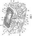
- FIG. 1is an isometric view of one form of an intervertebral spine implant fashioned in accordance with the present principles
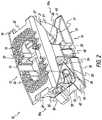
- FIG. 2is another isometric view of the intervertebral spine implant of FIG. 1 , upside down and reversed relative to FIG. 1 ;
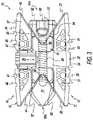
- FIG. 3is a side view of the intervertebral spine implant of FIG. 1 ;
- FIG. 4is an isometric view of another form of an intervertebral spine implant fashioned in accordance with the present principles.
- FIGS. 1-3depict one form of a height adjustable intervertebral (interbody) spine implant (intervertebral spine implant) 10 fashioned in accordance with the present principles.
- the intervertebral spine implant 10is characterized by a first component 12 , a second component 14 , and height adjustment means, adjustor, adjustment mechanism, controllable drive, control drive, drive mechanism, screw drive, or the like (height adjustment mechanism) 16 all made from one or more bio-compatible materials.
- the first and second components 12 , 14are movable with respect to one another through manipulation of the height adjustment mechanism 16 .
- the first component 12 , the second component 14 , and/or the height adjustment mechanism 16may be 3-D printed, machined, or otherwise manufactured, as well as conventionally.
- the first component 12may be either the lower, inferior, or caudal component configured to abut a lower, inferior, or caudal vertebra or vertebral surface (not shown), or the upper, superior, or cephalad component configured to abut an upper, superior, or cephalad vertebra or vertebral surface (not shown), while accordingly, the second component 14 may be either the upper, superior, or cephalad component configured to abut an upper, superior, or cephalad vertebra or vertebral surface (not shown), or the lower, inferior, or caudal component configured to abut a lower, inferior, or caudal vertebra or vertebral surface (not shown).
- the height adjustment mechanism 16is user-operable to effect movement of the first and second components 12 , 14 relative to one another via first and second opposing wedges 50 , 51 so as to effect height adjustment (taller or shorter) of the intervertebral spine implant 10 .
- first component 12will hereinafter be discussed as being the lower component
- second component 14will be discussed as being the upper component, it being understood that the first component can be the upper component and the second component can be the lower component.
- the first component 12is characterized by a base, platform, body or the like 13 fashioned generally as a trapezoid having one side of parallel sides of a generally planar contact surface 18 that is configured to abut/contact a bone, boney surface, vertebral surface, vertebra, or the like (not shown) the other side of the parallel sides not discerned but opposite the side 18 .
- the contact surface 18includes an area 19 of a matrix, mesh, perforations, holes, openings, pores, or the like (collectively, matrix) that aid in fusion.
- the matrix 19surrounds a bore 20 that extends through the body 13 .
- the matrix area 19may be modified in pattern, placement and/or structure as desired or needed.
- the body 13is further characterized by a first lateral or side rail 21 and a second lateral or side rail 22 , the nomenclature first and second being arbitrary.
- a boss 23extends from a middle portion of the first lateral side rail 21 , the boss 23 configured to receive a flange 40 of a first lateral side rail 38 of the second component 14
- a boss 24extends from a middle portion of the second lateral side rail 22 , the boss 24 configured to receive a flange 39 of a first lateral side rail 37 of the second component 14 .
- Notches 29are formed on the top of the first lateral side rail 21 to, at least, aid in retention and/or insertion of the body 13
- notches 30are formed on the top of the second lateral side rail 22 to, at least, aid in retention and/or insertion of the body 13
- a cutout 25is formed on one or first end 70 of the body 13 at the contact surface 18
- a cutout 26is formed on the other or second end 71 of the body 13 at the contact surface 18 .
- the first lateral side rail 21is shown without a matrix (as defined above) while the lateral side rail 22 is shown with a matrix 31 (as defined above). It should be appreciated that both side rails 21 , 22 may or may not have a matrix, thereby creating more forms of the invention.
- the contact surface 18is the long side and the surface 62 is the short side of the parallel sides.
- a surface 27is defined as one of the skew sides of the trapezoid body 13 that is adjacenet the cutout 25 and below the contact surface 18 while a surface 28 is defined as another one of the skew sides of the trapezoid body 13 that is adjacent the cutout 26 and below the contact surface 18 .
- the surface 27slopes or angles inwardly.
- the surface 28slopes or angles inwardly.
- the second component 14is characterized by a base, platform, body or the like 15 fashioned generally as a trapezoid having one side of parallel sides of a generally planar contact surface 34 that is configured to abut/contact a bone, boney surface, vertebral surface, vertebra, or the like (not shown) the other side of the parallel side 61 opposite the side 34 .
- the contact surface 34includes an area 35 of a matrix, mesh, perforations, holes, openings, pores, or the like (collectively, matrix) that aid in fusion.
- the matrix 35surrounds a bore 36 that extends through the body 15 .
- the matrix area 35may be modified in pattern, placement and/or structure as desired or needed.
- the body 15is further characterized by a third lateral or side rail 37 and a fourth lateral or side rail 38 .
- a flange 39extends from a middle portion of the third lateral side rail 37 , the flange 39 configured to be received in the boss 24 of the lateral side rail 22 of the first component 12
- a flange 40extends from a middle portion of the fourth lateral side rail 38 , the flange 40 configured to be received in the boss 23 of the lateral side rail 21 of the first component 14 .
- Notches 45are formed on the top of the side rail 37 to, at least, aid in retention and/or insertion of the body 15
- notches 46are formed on the top of the side rail 38 to, at least, aid in retention and/or insertion of the body 15
- a cutout 41is formed on one or first end 72 of the body 15 at the contact surface 34
- a cutout 42is formed on the other or second end 73 of the body 15 at the contact surface 34 .
- the lateral side rail 38is shown without a matrix (as defined above) while the lateral side rail 37 is shown with a matrix 47 (as defined above). It should be appreciated that both side rails 37 , 38 may or may not have a matrix, thereby creating more forms of the invention.
- the contact surface 34is the long side and the surface 61 is the short side of the parallel sides.
- the height adjustment means 16may be characterized by a first wedge 50 situated between the surface 27 of the skew side of the first component 12 and the surface 43 of the skew side of the second component 14 thereby forming a first pocket 16 a , a second wedge 51 situated between the skew surface 28 of the first component 12 and the skew surface 44 of the second component 14 thereby forming a second pocket 16 b , the nomenclature first and second being arbitrary, and a drive screw or the like 58 connected between the first and second wedges 50 , 51 and, in particular, is connected to threaded bores/openings 98 , 99 in the first and second wedges 50 , 51 , the threaded openings being reverse threaded relative to one another in order for the drive screw 58 to concertedly move the first and second wedges 50 , 51 either towards or away from each other depending on the rotational direction of the drive screw 58 .
- the drive screwmay constitute the height adjustment mechanism for the first and second wedges 50 , 51 .
- the first wedge 50includes a first lateral opening 50 and a second lateral opening 51 opposite the first lateral opening 50 , the nomenclature first and second being arbitrary.
- the second wedge 51does not have lateral openings but can if desired.
- a socket 60is situated at an end of the drive screw 58 that is configured to receive a drive tool (not shown) for rotating the drive screw 58 to adjust implant height.
- Rotation of the drive screw 58 in one directionincreases implant height by bringing the first and second wedges 50 , 51 toward each other (contraction), while rotation of the drive screw 58 in the opposite direction decreases implant height by spreading the first and second wedges 50 , 51 away from each other (expansion).
- the first wedge 50has a first sloped or angled surface 54 and a second sloped or angled surface 55 opposite the first sloped surface 54 , the nomenclature first and second being arbitrary.
- the first sloped surface 54abuts the angled surface (skew side) 27 of the first component 12
- the second sloped surface 55abuts the angled surface (skew side) 43 of the second component 14 .
- the second wedge 51has a third sloped or angled surface 56 and a fourth sloped or angled surface 57 opposite the third sloped surface 56 , the nomenclature third and fourth being arbitrary.
- the third sloped surface 56abuts the angled surface (skew side) 27 of the first component 12
- the fourth sloped surface 57abuts the angled surface (skew side) 43 of the second component 14 .
- first and second wedges 50 , 51are pulled together by rotation of the drive screw 58 via a drive tool (not shown) in the socket 60 in one direction, the wedges 50 , 51 move within the respective first and second pockets to push against the first and second components 12 , 14 to expand them relative to one another in order to increase implant height.
- the wedges 50 , 51are pushed away by rotation of the drive screw 58 via the drive tool in the socket 60 in the opposite direction, the wedges 50 , 51 move within the respective first and second pockets to relieve pressure against the first and second components 12 , 14 to allow them to contract relative to one another in order to decrease implant height.
- FIG. 4depicts another form of an intervertebral spine implant 110 fashioned in accordance with the present principles that has the exact same components as the intervertebral spine implant 10 , and thus has the same numbering and therefore function, configuration and description as the intervertebral spine implant 10 with the exception of the following additional components.
- the first wedge 50has a spherical pocket 112 disposed at its apex with a ball 113 disposed therein.
- the second wedge 51has a spherical pocket 114 disposed at its apex with a ball 115 disposed therein.
- the ball 113has a threaded bore therein.
- the ball 115also has a threaded bore therein that is opposite in threading to the threading of the threaded bore of the ball 113 .
- the drive screw 58extends through the threaded bore of the ball 113 and the threaded bore of the threaded bore of the ball 115 . Rotation of the drive screw 58 in one direction pulls the first and second wedges 50 , 51 together to effect an increase in height of the intervertebral spine implant 110 , while rotation of the drive screw 58 in the opposite direction pushes the first and second wedges 50 , 51 away to effect a decrease in height of the intervertebral spine implant 110 .
Landscapes
- Health & Medical Sciences (AREA)
- Engineering & Computer Science (AREA)
- Biomedical Technology (AREA)
- Neurology (AREA)
- Orthopedic Medicine & Surgery (AREA)
- Cardiology (AREA)
- Oral & Maxillofacial Surgery (AREA)
- Transplantation (AREA)
- Heart & Thoracic Surgery (AREA)
- Vascular Medicine (AREA)
- Life Sciences & Earth Sciences (AREA)
- Animal Behavior & Ethology (AREA)
- General Health & Medical Sciences (AREA)
- Public Health (AREA)
- Veterinary Medicine (AREA)
- Prostheses (AREA)
Abstract
Description
Claims (4)
Priority Applications (1)
| Application Number | Priority Date | Filing Date | Title |
|---|---|---|---|
| US16/287,003US10993814B2 (en) | 2018-02-27 | 2019-02-27 | Height adjustable spine implant |
Applications Claiming Priority (2)
| Application Number | Priority Date | Filing Date | Title |
|---|---|---|---|
| US201862635887P | 2018-02-27 | 2018-02-27 | |
| US16/287,003US10993814B2 (en) | 2018-02-27 | 2019-02-27 | Height adjustable spine implant |
Publications (2)
| Publication Number | Publication Date |
|---|---|
| US20190262139A1 US20190262139A1 (en) | 2019-08-29 |
| US10993814B2true US10993814B2 (en) | 2021-05-04 |
Family
ID=66286955
Family Applications (1)
| Application Number | Title | Priority Date | Filing Date |
|---|---|---|---|
| US16/287,003ActiveUS10993814B2 (en) | 2018-02-27 | 2019-02-27 | Height adjustable spine implant |
Country Status (2)
| Country | Link |
|---|---|
| US (1) | US10993814B2 (en) |
| WO (1) | WO2019169036A1 (en) |
Cited By (18)
| Publication number | Priority date | Publication date | Assignee | Title |
|---|---|---|---|---|
| US11376134B1 (en) | 2020-11-05 | 2022-07-05 | Warsaw Orthopedic, Inc. | Dual expanding spinal implant, system, and method of use |
| US11395743B1 (en) | 2021-05-04 | 2022-07-26 | Warsaw Orthopedic, Inc. | Externally driven expandable interbody and related methods |
| US11464649B2 (en)* | 2019-09-11 | 2022-10-11 | L&K Biomed Co., Ltd. | Expandable spinal fusion cage |
| US11517363B2 (en) | 2020-11-05 | 2022-12-06 | Warsaw Orthopedic, Inc. | Screw driver and complimentary screws |
| US11517443B2 (en) | 2020-11-05 | 2022-12-06 | Warsaw Orthopedic, Inc. | Dual wedge expandable implant, system and method of use |
| US11612499B2 (en) | 2021-06-24 | 2023-03-28 | Warsaw Orthopedic, Inc. | Expandable interbody implant |
| US11638653B2 (en) | 2020-11-05 | 2023-05-02 | Warsaw Orthopedic, Inc. | Surgery instruments with a movable handle |
| US11806250B2 (en) | 2018-02-22 | 2023-11-07 | Warsaw Orthopedic, Inc. | Expandable spinal implant system and method of using same |
| US11833059B2 (en) | 2020-11-05 | 2023-12-05 | Warsaw Orthopedic, Inc. | Expandable inter-body device, expandable plate system, and associated methods |
| US11963881B2 (en) | 2020-11-05 | 2024-04-23 | Warsaw Orthopedic, Inc. | Expandable inter-body device, system, and method |
| US12121453B2 (en) | 2020-11-05 | 2024-10-22 | Warsaw Orthopedic, Inc. | Dual wedge expandable implant with eyelets, system, and method of use |
| US12171439B2 (en) | 2020-11-05 | 2024-12-24 | Warsaw Orthopedic, Inc. | Protected drill |
| US12239544B2 (en) | 2020-11-05 | 2025-03-04 | Warsaw Orthopedic, Inc. | Rhomboid shaped implants |
| US12295865B2 (en) | 2021-06-24 | 2025-05-13 | Warsaw Orthopedic, Inc. | Expandable interbody implant and corresponding inserter |
| US12318308B2 (en) | 2020-11-05 | 2025-06-03 | Warsaw Orthopedic, Inc. | Dual expandable inter-body device |
| US12318307B2 (en) | 2021-07-16 | 2025-06-03 | Blue Ocean Spine Gmbh | Adjustable spinal implants, associated instruments and methods |
| US12414863B2 (en) | 2021-06-24 | 2025-09-16 | Warsaw Orthopedic, Inc. | Expandable interbody implant and corresponding surgical tool |
| US12440349B2 (en) | 2022-02-04 | 2025-10-14 | Warsaw Orthopedic, Inc. | Expandable interbody implant and breakoff screw |
Families Citing this family (17)
| Publication number | Priority date | Publication date | Assignee | Title |
|---|---|---|---|---|
| US10449051B2 (en) | 2015-04-29 | 2019-10-22 | Institute for Musculoskeletal Science and Education, Ltd. | Implant with curved bone contacting elements |
| JP6768001B2 (en) | 2015-04-29 | 2020-10-14 | インスティテュート フォー マスキュロスケレタル サイエンス アンド エジュケイション,リミテッド | Coiled implants and systems and how to make them |
| US10492921B2 (en) | 2015-04-29 | 2019-12-03 | Institute for Musculoskeletal Science and Education, Ltd. | Implant with arched bone contacting elements |
| US11033394B2 (en) | 2016-10-25 | 2021-06-15 | Institute for Musculoskeletal Science and Education, Ltd. | Implant with multi-layer bone interfacing lattice |
| US10478312B2 (en) | 2016-10-25 | 2019-11-19 | Institute for Musculoskeletal Science and Education, Ltd. | Implant with protected fusion zones |
| EP3345575B1 (en)* | 2017-01-06 | 2023-08-16 | Ke Ling Biotech Limited | Expandable spinal interbody cage |
| US10512549B2 (en) | 2017-03-13 | 2019-12-24 | Institute for Musculoskeletal Science and Education, Ltd. | Implant with structural members arranged around a ring |
| US10357377B2 (en) | 2017-03-13 | 2019-07-23 | Institute for Musculoskeletal Science and Education, Ltd. | Implant with bone contacting elements having helical and undulating planar geometries |
| US10940015B2 (en) | 2017-11-21 | 2021-03-09 | Institute for Musculoskeletal Science and Education, Ltd. | Implant with improved flow characteristics |
| US10744001B2 (en) | 2017-11-21 | 2020-08-18 | Institute for Musculoskeletal Science and Education, Ltd. | Implant with improved bone contact |
| US10993814B2 (en)* | 2018-02-27 | 2021-05-04 | Life Spine, Inc. | Height adjustable spine implant |
| US11285014B1 (en) | 2020-11-05 | 2022-03-29 | Warsaw Orthopedic, Inc. | Expandable inter-body device, system, and method |
| US11291554B1 (en) | 2021-05-03 | 2022-04-05 | Medtronic, Inc. | Unibody dual expanding interbody implant |
| US12268614B2 (en) | 2021-06-24 | 2025-04-08 | Warsaw Orthopedic, Inc. | Interbody implant with adjusting shims |
| US11730608B2 (en) | 2021-07-13 | 2023-08-22 | Warsaw Orthopedic, Inc. | Monoblock expandable interbody implant |
| US11850163B2 (en) | 2022-02-01 | 2023-12-26 | Warsaw Orthopedic, Inc. | Interbody implant with adjusting shims |
| CN115919515B (en)* | 2023-03-14 | 2023-05-26 | 中国人民解放军总医院第一医学中心 | Intervertebral prosthesis |
Citations (11)
| Publication number | Priority date | Publication date | Assignee | Title |
|---|---|---|---|---|
| US5609635A (en)* | 1988-06-28 | 1997-03-11 | Michelson; Gary K. | Lordotic interbody spinal fusion implants |
| WO2013145176A1 (en) | 2012-03-28 | 2013-10-03 | Necディスプレイソリューションズ株式会社 | Projector exhaust device |
| US20150374507A1 (en)* | 2005-03-31 | 2015-12-31 | Life Spine, Inc. | Expandable spinal interbody and intravertebral body devices |
| EP3050540A1 (en) | 2015-01-27 | 2016-08-03 | K2M, Inc. | Spinal implant |
| US20170224504A1 (en) | 2013-03-13 | 2017-08-10 | Life Spine, Inc. | Expandable spinal interbody assembly |
| US20170224505A1 (en)* | 2013-03-13 | 2017-08-10 | Life Spine, Inc. | Expandable spinal interbody assembly |
| US20170367842A1 (en) | 2013-03-13 | 2017-12-28 | Life Spine, Inc. | Expandable implant assembly |
| US20180185164A1 (en)* | 2015-07-14 | 2018-07-05 | Nlt Spine Ltd. | Expandable implant with deflectable sequence of segments |
| US20180296361A1 (en)* | 2013-03-13 | 2018-10-18 | Life Spine, Inc. | Expandable spinal interbody assembly |
| US20190262139A1 (en)* | 2018-02-27 | 2019-08-29 | Life Spine, Inc. | Height Adjustable Spine Implant |
| US20190343644A1 (en)* | 2018-05-08 | 2019-11-14 | Globus Medical, Inc. | Intervertebral spinal implant |
Family Cites Families (1)
| Publication number | Priority date | Publication date | Assignee | Title |
|---|---|---|---|---|
| EP2830542B1 (en)* | 2012-03-28 | 2021-10-27 | Innova Spinal Technologies, LLC | Expandable intervertebral implant |
- 2019
- 2019-02-27USUS16/287,003patent/US10993814B2/enactiveActive
- 2019-02-27WOPCT/US2019/019898patent/WO2019169036A1/ennot_activeCeased
Patent Citations (11)
| Publication number | Priority date | Publication date | Assignee | Title |
|---|---|---|---|---|
| US5609635A (en)* | 1988-06-28 | 1997-03-11 | Michelson; Gary K. | Lordotic interbody spinal fusion implants |
| US20150374507A1 (en)* | 2005-03-31 | 2015-12-31 | Life Spine, Inc. | Expandable spinal interbody and intravertebral body devices |
| WO2013145176A1 (en) | 2012-03-28 | 2013-10-03 | Necディスプレイソリューションズ株式会社 | Projector exhaust device |
| US20170224504A1 (en) | 2013-03-13 | 2017-08-10 | Life Spine, Inc. | Expandable spinal interbody assembly |
| US20170224505A1 (en)* | 2013-03-13 | 2017-08-10 | Life Spine, Inc. | Expandable spinal interbody assembly |
| US20170367842A1 (en) | 2013-03-13 | 2017-12-28 | Life Spine, Inc. | Expandable implant assembly |
| US20180296361A1 (en)* | 2013-03-13 | 2018-10-18 | Life Spine, Inc. | Expandable spinal interbody assembly |
| EP3050540A1 (en) | 2015-01-27 | 2016-08-03 | K2M, Inc. | Spinal implant |
| US20180185164A1 (en)* | 2015-07-14 | 2018-07-05 | Nlt Spine Ltd. | Expandable implant with deflectable sequence of segments |
| US20190262139A1 (en)* | 2018-02-27 | 2019-08-29 | Life Spine, Inc. | Height Adjustable Spine Implant |
| US20190343644A1 (en)* | 2018-05-08 | 2019-11-14 | Globus Medical, Inc. | Intervertebral spinal implant |
Cited By (24)
| Publication number | Priority date | Publication date | Assignee | Title |
|---|---|---|---|---|
| US11806250B2 (en) | 2018-02-22 | 2023-11-07 | Warsaw Orthopedic, Inc. | Expandable spinal implant system and method of using same |
| US12036132B2 (en) | 2018-02-22 | 2024-07-16 | Warsaw Orthopedic, Inc. | Expandable spinal implant system and method of using same |
| US11464649B2 (en)* | 2019-09-11 | 2022-10-11 | L&K Biomed Co., Ltd. | Expandable spinal fusion cage |
| US11638653B2 (en) | 2020-11-05 | 2023-05-02 | Warsaw Orthopedic, Inc. | Surgery instruments with a movable handle |
| US11833059B2 (en) | 2020-11-05 | 2023-12-05 | Warsaw Orthopedic, Inc. | Expandable inter-body device, expandable plate system, and associated methods |
| US11564724B2 (en) | 2020-11-05 | 2023-01-31 | Warsaw Orthopedic, Inc. | Expandable inter-body device, system and method |
| US11376134B1 (en) | 2020-11-05 | 2022-07-05 | Warsaw Orthopedic, Inc. | Dual expanding spinal implant, system, and method of use |
| US11617658B2 (en) | 2020-11-05 | 2023-04-04 | Warsaw Orthopedic, Inc. | Expandable inter-body device, system and method |
| US12318308B2 (en) | 2020-11-05 | 2025-06-03 | Warsaw Orthopedic, Inc. | Dual expandable inter-body device |
| US11517363B2 (en) | 2020-11-05 | 2022-12-06 | Warsaw Orthopedic, Inc. | Screw driver and complimentary screws |
| US11517443B2 (en) | 2020-11-05 | 2022-12-06 | Warsaw Orthopedic, Inc. | Dual wedge expandable implant, system and method of use |
| US11963881B2 (en) | 2020-11-05 | 2024-04-23 | Warsaw Orthopedic, Inc. | Expandable inter-body device, system, and method |
| US11969196B2 (en) | 2020-11-05 | 2024-04-30 | Warsaw Orthopedic, Inc. | Expandable inter-body device, system, and method |
| US12364529B2 (en) | 2020-11-05 | 2025-07-22 | Warsaw Orthopedic, Inc. | Expandable inter-body device, system, and method |
| US12053392B2 (en) | 2020-11-05 | 2024-08-06 | Warsaw Orthopedic, Inc. | Expandable inter-body device, expandable plate system, and associated methods |
| US12121453B2 (en) | 2020-11-05 | 2024-10-22 | Warsaw Orthopedic, Inc. | Dual wedge expandable implant with eyelets, system, and method of use |
| US12171439B2 (en) | 2020-11-05 | 2024-12-24 | Warsaw Orthopedic, Inc. | Protected drill |
| US12239544B2 (en) | 2020-11-05 | 2025-03-04 | Warsaw Orthopedic, Inc. | Rhomboid shaped implants |
| US11395743B1 (en) | 2021-05-04 | 2022-07-26 | Warsaw Orthopedic, Inc. | Externally driven expandable interbody and related methods |
| US11612499B2 (en) | 2021-06-24 | 2023-03-28 | Warsaw Orthopedic, Inc. | Expandable interbody implant |
| US12295865B2 (en) | 2021-06-24 | 2025-05-13 | Warsaw Orthopedic, Inc. | Expandable interbody implant and corresponding inserter |
| US12414863B2 (en) | 2021-06-24 | 2025-09-16 | Warsaw Orthopedic, Inc. | Expandable interbody implant and corresponding surgical tool |
| US12318307B2 (en) | 2021-07-16 | 2025-06-03 | Blue Ocean Spine Gmbh | Adjustable spinal implants, associated instruments and methods |
| US12440349B2 (en) | 2022-02-04 | 2025-10-14 | Warsaw Orthopedic, Inc. | Expandable interbody implant and breakoff screw |
Also Published As
| Publication number | Publication date |
|---|---|
| WO2019169036A1 (en) | 2019-09-06 |
| US20190262139A1 (en) | 2019-08-29 |
Similar Documents
| Publication | Publication Date | Title |
|---|---|---|
| US10993814B2 (en) | Height adjustable spine implant | |
| US10869769B2 (en) | Intervertebral cages with integrated expansion and angular adjustment mechanism | |
| US12138177B2 (en) | Expandable intervertebral implant | |
| US10722379B2 (en) | Expandable intervertebral implant | |
| US11752005B2 (en) | Expandable spinal implant system and method of using same | |
| US11065129B2 (en) | Expandable intervertebral fusion device | |
| US11083592B2 (en) | Plastically deformable inter-osseous device | |
| US12193949B2 (en) | Expanding orthopedic implant | |
| US20220000632A1 (en) | Intervertebral spacer and plate | |
| US20100241231A1 (en) | Intervertebral fixation device | |
| US9204973B2 (en) | Laterally expandable interbody fusion cage | |
| EP3622920B1 (en) | Expandable intervertebral implant |
Legal Events
| Date | Code | Title | Description |
|---|---|---|---|
| FEPP | Fee payment procedure | Free format text:ENTITY STATUS SET TO UNDISCOUNTED (ORIGINAL EVENT CODE: BIG.); ENTITY STATUS OF PATENT OWNER: SMALL ENTITY | |
| AS | Assignment | Owner name:LIFE SPINE, INC., ILLINOIS Free format text:ASSIGNMENT OF ASSIGNORS INTEREST;ASSIGNOR:WOLTERS, MADELINE C.;REEL/FRAME:048462/0782 Effective date:20181102 | |
| FEPP | Fee payment procedure | Free format text:ENTITY STATUS SET TO SMALL (ORIGINAL EVENT CODE: SMAL); ENTITY STATUS OF PATENT OWNER: SMALL ENTITY | |
| STPP | Information on status: patent application and granting procedure in general | Free format text:RESPONSE TO NON-FINAL OFFICE ACTION ENTERED AND FORWARDED TO EXAMINER | |
| STPP | Information on status: patent application and granting procedure in general | Free format text:NOTICE OF ALLOWANCE MAILED -- APPLICATION RECEIVED IN OFFICE OF PUBLICATIONS | |
| AS | Assignment | Owner name:LIFE SPINE, INC., ILLINOIS Free format text:RELEASE BY SECURED PARTY;ASSIGNOR:FIFTH THIRD BANK, NATIONAL ASSOCIATION;REEL/FRAME:054843/0755 Effective date:20201218 Owner name:GIZMO MEDICAL, LLC, ILLINOIS Free format text:RELEASE BY SECURED PARTY;ASSIGNOR:FIFTH THIRD BANK, NATIONAL ASSOCIATION;REEL/FRAME:054843/0755 Effective date:20201218 Owner name:ST. CLOUD CAPITAL PARTNERS III SBIC, LP, CALIFORNIA Free format text:SECURITY INTEREST;ASSIGNORS:LIFE SPINE, INC.;GIZMO MEDICAL, LLC;REEL/FRAME:054844/0239 Effective date:20201218 | |
| STPP | Information on status: patent application and granting procedure in general | Free format text:PUBLICATIONS -- ISSUE FEE PAYMENT RECEIVED | |
| STPP | Information on status: patent application and granting procedure in general | Free format text:PUBLICATIONS -- ISSUE FEE PAYMENT VERIFIED | |
| STCF | Information on status: patent grant | Free format text:PATENTED CASE | |
| AS | Assignment | Owner name:ASSOCIATED BANK, NATIONAL ASSOCIATION, AS AGENT, ILLINOIS Free format text:SECURITY INTEREST;ASSIGNOR:LIFE SPINE, INC.;REEL/FRAME:056728/0438 Effective date:20210630 | |
| AS | Assignment | Owner name:LIFE SPINE, INC., ILLINOIS Free format text:RELEASE BY SECURED PARTY;ASSIGNOR:ASSOCIATED BANK, NATIONAL ASSOCIATION;REEL/FRAME:064275/0446 Effective date:20230526 | |
| FEPP | Fee payment procedure | Free format text:MAINTENANCE FEE REMINDER MAILED (ORIGINAL EVENT CODE: REM.); ENTITY STATUS OF PATENT OWNER: SMALL ENTITY | |
| FEPP | Fee payment procedure | Free format text:SURCHARGE FOR LATE PAYMENT, SMALL ENTITY (ORIGINAL EVENT CODE: M2554); ENTITY STATUS OF PATENT OWNER: SMALL ENTITY | |
| MAFP | Maintenance fee payment | Free format text:PAYMENT OF MAINTENANCE FEE, 4TH YR, SMALL ENTITY (ORIGINAL EVENT CODE: M2551); ENTITY STATUS OF PATENT OWNER: SMALL ENTITY Year of fee payment:4 |