US10993760B2 - Modular surgical robotic tool - Google Patents
Modular surgical robotic toolDownload PDFInfo
- Publication number
- US10993760B2 US10993760B2US15/238,022US201615238022AUS10993760B2US 10993760 B2US10993760 B2US 10993760B2US 201615238022 AUS201615238022 AUS 201615238022AUS 10993760 B2US10993760 B2US 10993760B2
- Authority
- US
- United States
- Prior art keywords
- tool driver
- tool
- tool assembly
- time period
- electromechanical arm
- Prior art date
- Legal status (The legal status is an assumption and is not a legal conclusion. Google has not performed a legal analysis and makes no representation as to the accuracy of the status listed.)
- Active, expires
Links
- 239000012636effectorSubstances0.000claimsabstractdescription66
- 230000015654memoryEffects0.000claimsabstractdescription47
- 230000033001locomotionEffects0.000claimsabstractdescription45
- 238000000034methodMethods0.000claimsdescription32
- 238000004891communicationMethods0.000claimsdescription24
- 238000012545processingMethods0.000claimsdescription17
- 238000012546transferMethods0.000claimsdescription16
- 238000001356surgical procedureMethods0.000description17
- 238000003860storageMethods0.000description9
- 230000000712assemblyEffects0.000description7
- 238000000429assemblyMethods0.000description7
- 230000003287optical effectEffects0.000description6
- 230000008878couplingEffects0.000description5
- 238000010168coupling processMethods0.000description5
- 238000005859coupling reactionMethods0.000description5
- 230000008901benefitEffects0.000description4
- 238000004590computer programMethods0.000description4
- 238000005520cutting processMethods0.000description4
- 230000006870functionEffects0.000description4
- 230000000670limiting effectEffects0.000description4
- 230000005855radiationEffects0.000description4
- 230000000007visual effectEffects0.000description4
- 230000009471actionEffects0.000description3
- 238000004140cleaningMethods0.000description3
- 238000002432robotic surgeryMethods0.000description3
- 230000001954sterilising effectEffects0.000description3
- 230000001052transient effectEffects0.000description3
- 241001631457CannulaSpecies0.000description2
- 210000000683abdominal cavityAnatomy0.000description2
- 230000004888barrier functionEffects0.000description2
- 238000010304firingMethods0.000description2
- 230000003993interactionEffects0.000description2
- 239000004973liquid crystal related substanceSubstances0.000description2
- 238000004519manufacturing processMethods0.000description2
- 238000002324minimally invasive surgeryMethods0.000description2
- 210000000056organAnatomy0.000description2
- 230000036961partial effectEffects0.000description2
- 230000037361pathwayEffects0.000description2
- 238000013515scriptMethods0.000description2
- 241000894006BacteriaSpecies0.000description1
- IAYPIBMASNFSPL-UHFFFAOYSA-NEthylene oxideChemical compoundC1CO1IAYPIBMASNFSPL-UHFFFAOYSA-N0.000description1
- 239000004775TyvekSubstances0.000description1
- 229920000690TyvekPolymers0.000description1
- 210000001015abdomenAnatomy0.000description1
- 210000003815abdominal wallAnatomy0.000description1
- 210000003484anatomyAnatomy0.000description1
- 238000003491arrayMethods0.000description1
- 210000004204blood vesselAnatomy0.000description1
- 230000008859changeEffects0.000description1
- 238000013461designMethods0.000description1
- 238000001514detection methodMethods0.000description1
- 238000006073displacement reactionMethods0.000description1
- 238000002224dissectionMethods0.000description1
- 238000002674endoscopic surgeryMethods0.000description1
- 238000005516engineering processMethods0.000description1
- 238000003384imaging methodMethods0.000description1
- 230000002262irrigationEffects0.000description1
- 238000003973irrigationMethods0.000description1
- 238000002357laparoscopic surgeryMethods0.000description1
- 239000007788liquidSubstances0.000description1
- 238000012423maintenanceMethods0.000description1
- 230000007246mechanismEffects0.000description1
- 238000012978minimally invasive surgical procedureMethods0.000description1
- 238000012986modificationMethods0.000description1
- 230000004048modificationEffects0.000description1
- 238000002355open surgical procedureMethods0.000description1
- 230000002085persistent effectEffects0.000description1
- 230000002980postoperative effectEffects0.000description1
- 238000002360preparation methodMethods0.000description1
- 230000008569processEffects0.000description1
- 238000011084recoveryMethods0.000description1
- 230000002829reductive effectEffects0.000description1
- 230000004044responseEffects0.000description1
- 230000000717retained effectEffects0.000description1
- 239000000523sampleSubstances0.000description1
- 230000037390scarringEffects0.000description1
- 230000035945sensitivityEffects0.000description1
- 230000001953sensory effectEffects0.000description1
- 230000003068static effectEffects0.000description1
- 238000004659sterilization and disinfectionMethods0.000description1
- 230000001360synchronised effectEffects0.000description1
- 230000001225therapeutic effectEffects0.000description1
- 238000013519translationMethods0.000description1
- 238000002604ultrasonographyMethods0.000description1
- 210000000707wristAnatomy0.000description1
Images


Classifications
- B—PERFORMING OPERATIONS; TRANSPORTING
- B25—HAND TOOLS; PORTABLE POWER-DRIVEN TOOLS; MANIPULATORS
- B25J—MANIPULATORS; CHAMBERS PROVIDED WITH MANIPULATION DEVICES
- B25J13/00—Controls for manipulators
- B25J13/006—Controls for manipulators by means of a wireless system for controlling one or several manipulators
- A—HUMAN NECESSITIES
- A61—MEDICAL OR VETERINARY SCIENCE; HYGIENE
- A61B—DIAGNOSIS; SURGERY; IDENTIFICATION
- A61B18/00—Surgical instruments, devices or methods for transferring non-mechanical forms of energy to or from the body
- A61B18/04—Surgical instruments, devices or methods for transferring non-mechanical forms of energy to or from the body by heating
- A61B18/08—Surgical instruments, devices or methods for transferring non-mechanical forms of energy to or from the body by heating by means of electrically-heated probes
- A61B18/10—Power sources therefor
- A—HUMAN NECESSITIES
- A61—MEDICAL OR VETERINARY SCIENCE; HYGIENE
- A61B—DIAGNOSIS; SURGERY; IDENTIFICATION
- A61B34/00—Computer-aided surgery; Manipulators or robots specially adapted for use in surgery
- A61B34/30—Surgical robots
- A—HUMAN NECESSITIES
- A61—MEDICAL OR VETERINARY SCIENCE; HYGIENE
- A61B—DIAGNOSIS; SURGERY; IDENTIFICATION
- A61B34/00—Computer-aided surgery; Manipulators or robots specially adapted for use in surgery
- A61B34/30—Surgical robots
- A61B34/35—Surgical robots for telesurgery
- A—HUMAN NECESSITIES
- A61—MEDICAL OR VETERINARY SCIENCE; HYGIENE
- A61B—DIAGNOSIS; SURGERY; IDENTIFICATION
- A61B34/00—Computer-aided surgery; Manipulators or robots specially adapted for use in surgery
- A61B34/30—Surgical robots
- A61B34/37—Leader-follower robots
- A—HUMAN NECESSITIES
- A61—MEDICAL OR VETERINARY SCIENCE; HYGIENE
- A61B—DIAGNOSIS; SURGERY; IDENTIFICATION
- A61B34/00—Computer-aided surgery; Manipulators or robots specially adapted for use in surgery
- A61B34/70—Manipulators specially adapted for use in surgery
- A—HUMAN NECESSITIES
- A61—MEDICAL OR VETERINARY SCIENCE; HYGIENE
- A61B—DIAGNOSIS; SURGERY; IDENTIFICATION
- A61B90/00—Instruments, implements or accessories specially adapted for surgery or diagnosis and not covered by any of the groups A61B1/00 - A61B50/00, e.g. for luxation treatment or for protecting wound edges
- A61B90/90—Identification means for patients or instruments, e.g. tags
- A61B90/98—Identification means for patients or instruments, e.g. tags using electromagnetic means, e.g. transponders
- B—PERFORMING OPERATIONS; TRANSPORTING
- B25—HAND TOOLS; PORTABLE POWER-DRIVEN TOOLS; MANIPULATORS
- B25J—MANIPULATORS; CHAMBERS PROVIDED WITH MANIPULATION DEVICES
- B25J13/00—Controls for manipulators
- B25J13/08—Controls for manipulators by means of sensing devices, e.g. viewing or touching devices
- B25J13/088—Controls for manipulators by means of sensing devices, e.g. viewing or touching devices with position, velocity or acceleration sensors
- B25J13/089—Determining the position of the robot with reference to its environment
- B—PERFORMING OPERATIONS; TRANSPORTING
- B25—HAND TOOLS; PORTABLE POWER-DRIVEN TOOLS; MANIPULATORS
- B25J—MANIPULATORS; CHAMBERS PROVIDED WITH MANIPULATION DEVICES
- B25J15/00—Gripping heads and other end effectors
- B25J15/04—Gripping heads and other end effectors with provision for the remote detachment or exchange of the head or parts thereof
- B25J15/0408—Connections means
- B—PERFORMING OPERATIONS; TRANSPORTING
- B25—HAND TOOLS; PORTABLE POWER-DRIVEN TOOLS; MANIPULATORS
- B25J—MANIPULATORS; CHAMBERS PROVIDED WITH MANIPULATION DEVICES
- B25J9/00—Programme-controlled manipulators
- B25J9/0084—Programme-controlled manipulators comprising a plurality of manipulators
- A—HUMAN NECESSITIES
- A61—MEDICAL OR VETERINARY SCIENCE; HYGIENE
- A61B—DIAGNOSIS; SURGERY; IDENTIFICATION
- A61B17/00—Surgical instruments, devices or methods
- A61B2017/00017—Electrical control of surgical instruments
- A61B2017/00221—Electrical control of surgical instruments with wireless transmission of data, e.g. by infrared radiation or radiowaves
- A—HUMAN NECESSITIES
- A61—MEDICAL OR VETERINARY SCIENCE; HYGIENE
- A61B—DIAGNOSIS; SURGERY; IDENTIFICATION
- A61B17/00—Surgical instruments, devices or methods
- A61B2017/00477—Coupling
- A—HUMAN NECESSITIES
- A61—MEDICAL OR VETERINARY SCIENCE; HYGIENE
- A61B—DIAGNOSIS; SURGERY; IDENTIFICATION
- A61B17/00—Surgical instruments, devices or methods
- A61B2017/00681—Aspects not otherwise provided for
- A61B2017/00734—Aspects not otherwise provided for battery operated
- A—HUMAN NECESSITIES
- A61—MEDICAL OR VETERINARY SCIENCE; HYGIENE
- A61B—DIAGNOSIS; SURGERY; IDENTIFICATION
- A61B18/00—Surgical instruments, devices or methods for transferring non-mechanical forms of energy to or from the body
- A61B2018/00636—Sensing and controlling the application of energy
- A—HUMAN NECESSITIES
- A61—MEDICAL OR VETERINARY SCIENCE; HYGIENE
- A61B—DIAGNOSIS; SURGERY; IDENTIFICATION
- A61B18/00—Surgical instruments, devices or methods for transferring non-mechanical forms of energy to or from the body
- A61B2018/00964—Features of probes
- A—HUMAN NECESSITIES
- A61—MEDICAL OR VETERINARY SCIENCE; HYGIENE
- A61B—DIAGNOSIS; SURGERY; IDENTIFICATION
- A61B18/00—Surgical instruments, devices or methods for transferring non-mechanical forms of energy to or from the body
- A61B2018/00988—Means for storing information, e.g. calibration constants, or for preventing excessive use, e.g. usage, service life counter
- A—HUMAN NECESSITIES
- A61—MEDICAL OR VETERINARY SCIENCE; HYGIENE
- A61B—DIAGNOSIS; SURGERY; IDENTIFICATION
- A61B90/00—Instruments, implements or accessories specially adapted for surgery or diagnosis and not covered by any of the groups A61B1/00 - A61B50/00, e.g. for luxation treatment or for protecting wound edges
- A61B90/08—Accessories or related features not otherwise provided for
- A61B2090/0813—Accessories designed for easy sterilising, i.e. re-usable
Definitions
- Methods and devicesare provided for robotic surgery, and in particular for wireless communications between components of a robotic surgical system.
- MISMinimally invasive surgical
- Laparoscopic surgeryis one type of MIS procedure in which one or more small incisions are formed in the abdomen and a trocar is inserted through the incision to form a pathway that provides access to the abdominal cavity.
- the trocaris used to introduce various instruments and tools into the abdominal cavity, as well as to provide insufflation to elevate the abdominal wall above the organs.
- the instruments and toolscan be used to engage and/or treat tissue in a number of ways to achieve a diagnostic or therapeutic effect.
- Endoscopic surgeryis another type of MIS procedure in which elongate flexible shafts are introduced into the body through a natural orifice.
- Telesurgeryis a general term for surgical operations using systems where the surgeon uses some form of remote control, e.g., a servomechanism, or the like, to manipulate surgical instrument movements, rather than directly holding and moving the tools by hand.
- the surgeonis typically provided with an image of the surgical site on a visual display at a location remote from the patient.
- the surgeoncan typically perform the surgical procedure at the location remote from the patient whilst viewing the end effector movement on the visual display during the surgical procedure. While viewing typically a three-dimensional image of the surgical site on the visual display, the surgeon performs the surgical procedures on the patient by manipulating master control devices at the remote location, which master control devices control motion of the remotely controlled instruments.
- a systemin some embodiments includes a first electromechanical arm configured for movement in multiple axes and a second electromechanical arm configured for movement in multiple axes, a tool driver attached to the first electromechanical arm such that power is supplied to the tool driver from the first electromechanical arm, and wherein the tool driver includes a wireless interface and a battery enabling removal of the tool driver from the first electromechanical arm and placement of the tool driver in the second electromechanical arm without restarting the tool driver, and a processing unit in wireless communication with the tool driver.
- the tool drivercan include at least one of a radio frequency generator and an ultrasonic transducer.
- the tool drivercan include at least a memory, wherein the memory is configured to store calibration information related to the at least one of the radio frequency generator, the ultrasonic transducer, and usage information related to the tool driver.
- the tool driverincludes an end effector that is at least one of released and reloaded after the tool driver is removed from the first electromechanical arm.
- the systemincludes a sensor configured to determine one or more position changes when the tool driver was moved from the first electromechanical arm to the second electromechanical arm.
- the sensorcan include at least one of an accelerometer, a gyro, a relative position sensor, and a three-dimensional magnetic sensor.
- the sensorcan be configured to generate position information characterizing the one or more position changes, wherein the position information is transmitted via the wireless interface from the tool driver to the processing unit.
- a methodin some embodiments includes attaching a tool driver that includes an energy transducer and a wireless interface configured to communicate to a processing unit to a first electromechanical arm of a surgical robot such that the first electromechanical arm provides electrical power to the tool driver, removing the tool driver from the first electromechanical arm, wherein after removal from the first electromechanical arm, the tool driver continues to communicate with the processing unit via the wireless interface, wherein electrical power is provided to the tool driver by a battery, and attaching the tool driver to a second electromechanical arm of the surgical robot, wherein when the tool driver is attached to the second electromechanical arm, the second electromechanical arm provides electrical power to the tool driver.
- the tool drivercontinues to communicate with the processing using via the wireless interface.
- the energy transducercan include at least one of a radio frequency generator and an ultrasonic transducer.
- the tool driverincludes at least a memory, wherein the memory stores calibration information related to the at least one of the radio frequency end effector, the ultrasonic transducer, and usage information related to the tool driver.
- the tool drivercan include an end effector that is at least one of released and reloaded after the tool driver is removed from the first electromechanical arm.
- the tool drivercan include a sensor to determine one or more position changes when the tool driver was moved from the first electromechanical arm to the second electromechanical arm.
- the senorincludes at least one of an accelerometer, a gyro, a relative position sensor, and a three-dimensional magnetic sensor. In some embodiments, the sensor can generate position information characterizing the one or more position changes, wherein the position information is transmitted via the wireless interface from the tool driver to the processing unit.
- FIG. 1illustrates a perspective view of an embodiment of a surgical robotic system that includes a patient-side portion and a user-side portion with the patient-side portion including at least one robotic arm configured to releasably couple to a tool assembly;
- FIG. 2illustrates an embodiment of the robotic arm of FIG. 1 having an embodiment of a tool assembly releasably coupled to the robotic arm;
- FIG. 3illustrates a tool driver of the robotic arm of FIG. 2 having one or more motors that control a variety of movements and actions associated with the tool assembly;
- FIG. 4illustrates a part of a puck actuation assembly contained within the puck of the tool assembly of FIG. 2 ;
- FIG. 5illustrates the puck of FIG. 4 coupled to the driver with the actuators extending from the driver into the puck and engaging driving members;
- FIG. 6illustrates another embodiment of a robotic surgical system that includes a wireless communication system
- FIG. 7illustrates transferring a tool assembly from a first robotic arm to a second robotic arm
- FIG. 8Aillustrates another embodiment of a puck of a tool assembly
- FIG. 8Billustrates an end-view of the puck of FIG. 8A ;
- FIG. 9illustrates an embodiment of a modular shaft of a tool assembly
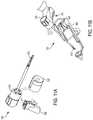
- FIGS. 10A and 10Billustrate an embodiment of a modular shaft that is swappable from a robotic arm ( FIG. 10A ) and a handle that can be manually manipulated ( FIG. 10B );
- FIGS. 11A and 11Billustrate an embodiment of a modular shaft that is swappable between a handle that can be manually manipulated ( FIG. 11 A) and a robotic arm ( FIG. 11B );
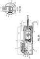
- FIG. 12Aillustrates another embodiment of a surgical tool including an adapter and a modular shaft configured in a robotic arm;
- FIG. 12Billustrates an expanded view of the surgical tool of FIG. 12A with an adapter and a modular shaft
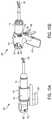
- FIG. 12Cillustrates an expanded view of the surgical tool of FIG. 12A configured for use with a handle that can be manually manipulated;
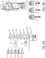
- FIG. 13Aillustrates various embodiments of modular transducers and modular shafts
- FIG. 13Billustrates various embodiments of modular tool drivers
- FIG. 14illustrates movement and rotation along one of the three axes in a Cartesian frame
- FIG. 15illustrates an exemplary embodiment of a computer system.
- like-named components of the embodimentsgenerally have similar features, and thus within a particular embodiment each feature of each like-named component is not necessarily fully elaborated upon.
- linear or circular dimensionsare used in the description of the disclosed systems, devices, and methods, such dimensions are not intended to limit the types of shapes that can be used in conjunction with such systems, devices, and methods.
- a person skilled in the artwill recognize that an equivalent to such linear and circular dimensions can easily be determined for any geometric shape. Sizes and shapes of the systems and devices, and the components thereof, can depend at least on the anatomy of the subject in which the systems and devices will be used, the size and shape of components with which the systems and devices will be used, and the methods and procedures in which the systems and devices will be used.
- the systems, devices, and methods disclosed hereincan be implemented using a robotic surgical system.
- a surgical robotic systemcan assist with performing surgical procedures on a patient. Such procedures can require the robotic surgical system to move at least one surgical arm and manipulate a tool assembly that is removably and replaceably coupled to each robotic arm.
- a tool assemblycan have an end effector that includes a cutting tool configured to assist with cutting tissue of a patient.
- the robotic surgical systemcan further include a control system that controls movement and manipulation of either the robotic arm or the tool assembly.
- a tool assemblycan be releasably coupled to a first robotic arm and can be configured by the control system while coupled to the first robotic arm. The tool assembly can assist with performing one or more parts of a surgical procedure and subsequently uncoupled from the first robotic arm.
- the tool assemblyAfter becoming uncoupled from the first robotic arm, the tool assembly can be either releasably coupled to a second robotic arm or used manually by a user. Such displacement of the tool assembly relative to the first robotic arm can result in loss of information related to the tool assembly, such as configuration information, location information, and status information. Such loss of information can be a result of the uncoupling of the tool assembly from the first robotic arm and can prolong surgical procedures due to the surgical robotic system having to either be re-calibrated or the user having to re-configure the tool assembly.
- the surgical robotic system described hereinincludes an embodiment of a wireless communication system that allows at least the tool assembly and control system to communicate wirelessly.
- control systemto continue sending and receiving information to and from the tool assembly regardless of whether the tool assembly is coupled to the robotic arm thereby allowing seamless transfer of the tool assembly between robotic arms and/or manual use.
- electronic communication between various components of the robotic surgical systemcan be either wired or wireless for assisting with seamless and continuing communication of data and information between at least the tool assembly and the control system.
- the tool assemblyis modular and includes more than one modular part that can be either removed or interchanged.
- Such modularitycan allow for easy replacement of one or more modular parts of the tool assembly, as well as allow for various configurations of the tool assembly.
- a modular tool assemblycan include an end effector that can be either removed or replaced, such as for switching tooling associated with the end effectors to assist with different parts of a surgical procedure. While removing, replacing, adding, and/or interchanging modular parts of one or more tool assemblies can provide advantages, such as allowing for a variety of tool assembly configurations, calibrating the modular tool assembly each time a modular part is removed, replaced, added, and/or interchanged can be time consuming.
- the surgical robotic system described hereinincludes another embodiment of a wireless communication system that allows a modular part of a tool assembly to communicate with the control system, robotic arm, and/or other modular parts of the tool assembly (or another tool assembly).
- Thisallows configuration information to be communicated between the control system, robotic arm, and/or modular parts of tool assemblies thereby reducing or eliminating time required to re-configure a tool assembly after removing, replacing, adding, and/or interchanging one or more modular parts
- a robotic surgical armcan include a tool assembly containing motors to drive an end effector.
- the tool assemblycan generate ultrasonic and/or radio frequency energy to apply to tissue disposed between the jaws of the end effector.
- the tool assemblycan include modular components such as a modular shaft that can include an ultrasonic transducer, nonvolatile memory, wireless interface, and/or a power source.
- the non-volatile memorycan allow the modular shaft to be attached to one robotic arm and moved to another robotic arm without restarting or recalibrating the ultrasonic driver.
- the power sourcecan allow the modular shaft to communicate wirelessly with the robotic arm while attached to a robotic arm, and after the modular shaft is detached from the robotic arm.
- the modular shaftcan also be moved from a robotic arm to a handle manually controlled by a surgeon and back again to the robotic arm.
- a tool assemblycan be “hot-swapped” or moved from one robotic arm to another while remaining powered.
- the tool assemblycan include sensors to determine a location or movement of the tool assembly.
- a power sourcecan allow the tool assembly to communicate wirelessly with the robotic while attached to a robotic arm and after the tool assembly is detached from the robotic arm.
- the tool assemblycan also be moved from a robotic arm to a handle manually controlled by a surgeon and back again to the robotic arm.
- FIG. 1is a perspective view of one embodiment of a surgical robotic system 300 that includes a patient-side portion 310 that is positioned adjacent to a patient 312 , and a user-side portion 311 that is located a distance from the patient, either in the same room and/or in a remote location.
- the patient-side portion 310generally includes one or more robotic arms 320 and one or more tool assemblies 330 that are configured to releasably couple to a robotic arm 320 .
- the user-side portion 311generally includes a vision system 313 for viewing the patient 312 and/or surgical site, and a control system 315 for controlling the movement of the robotic arms 320 and each tool assembly 330 during a surgical procedure.
- the control system 315can have a variety of configurations and it can be located adjacent to the patient, e.g., in the operating room, remote from the patient, e.g., in a separate control room, or it can be distributed at two or more locations.
- a dedicated system control consolecan be located in the operating room, and a separate console can be located in a remote location.
- the control system 315can include components that enable a user to view a surgical site of a patient 312 being operated on by the patient-side portion 310 and/or to control one or more parts of the patient-side portion 310 (e.g., to perform a surgical procedure at the surgical site 312 ).
- control system 315can also include one or more manually-operated input devices, such as a joystick, exoskeletal glove, a powered and gravity-compensated manipulator, or the like. These input devices can control teleoperated motors which, in turn, control the movement of the surgical system, including the robotic arms 320 and tool assemblies 330 .
- manually-operated input devicessuch as a joystick, exoskeletal glove, a powered and gravity-compensated manipulator, or the like.
- These input devicescan control teleoperated motors which, in turn, control the movement of the surgical system, including the robotic arms 320 and tool assemblies 330 .
- the patient-side portioncan also have a variety of configurations. As depicted in FIG. 1 , the patient-side portion 310 can couple to an operating table 314 . However, in some embodiments, the patient-side portion 310 can be mounted to a wall, to the ceiling, to the floor, or to other operating room equipment. Further, while the patient-side portion 310 is shown as including two robotic arms 320 , more or fewer robotic arms 320 can be included. Furthermore, the patient-side portion 310 can include separate robotic arms 320 mounted in various positions, such as relative to the surgical table 314 . Alternatively, the patient-side portion 310 can include a single assembly that includes one or more robotic arms 320 extending therefrom.
- FIG. 2illustrates another embodiment of a robotic arm 1120 and a tool assembly 1130 releasably coupled to the robotic arm 1120 .
- the robotic arm 1120can support and move the associated tool assembly 1130 along one or more mechanical degrees of freedom (e.g., all six Cartesian degrees of freedom, five or fewer Cartesian degrees of freedom, etc.).
- the robotic arm 1120can include a tool driver 1140 at a distal end of the robotic arm 1120 , which can assist with controlling features associated with the tool assembly 1130 .
- the robotic arm 1120can also include a movable tool guide 1132 that can retract and extend relative to the driver 1140 .
- a shaft of the tool assembly 1130can extend parallel to a threaded shaft of the movable tool guide 1132 and can extend through a distal end feature 1133 (e.g., a ring) of the movable tool guide 1130 and into a patient.
- a barrier(not shown) can be placed between the actuating portion of the surgical system (e.g., the robotic arm 1120 ) and the surgical instruments (e.g., the tool assembly 1130 ) in the sterile surgical field.
- a sterile componentsuch as an instrument sterile adapter (ISA)
- ISAinstrument sterile adapter
- the placement of an ISA between the tool assembly 1130 and the robotic arm 1120can ensure a sterile coupling point for the tool assembly 1130 and the robotic arm 1120 . This permits removal of tool assemblies 1130 from the robotic arm 1120 to exchange with other tool assemblies 1130 during the course of a surgery without compromising the sterile surgical field.
- FIG. 3illustrates the tool driver 1140 in more detail.
- the tool driver 1140includes one or more motors, e.g., seven motors M 1 -M 7 are shown, that control a variety of movements and actions associated with the tool assembly 1130 , as will be described in greater detail below.
- the driver 1140can also include one or more lead screws (e.g., three lead screws L 1 , L 2 , and L 3 are shown) that can be individually rotated by a motor and, as a result of the rotation of the lead screw, cause linear and/or rotational movement of at least one actuator (e.g., see, for example, actuators A 1 and A 2 shown in FIG. 3 ).
- Movement of each actuatorcontrols the movement of driving members (e.g., gears, cables) located in the tool assembly 1130 for controlling one or more actions and movements that can be performed by the tooling assembly 1130 , such as for assisting with performing a surgical operation.
- the actuatorsextend from a top end of the driver 1140 for coupling to the driving members of the tool assembly 1130 mounted on top of the tool driver 1140 .
- the tool assembly 1130can be loaded from a top side of the driver 1140 with the shaft of the tool assembly 1130 being positioned in a shaft-receiving channel 1144 formed along the side of the driver 1140 .
- the shaft-receiving channel 1144allows the shaft, which extends along a central axis of the tool assembly 1130 , to extend along a central axis of the driver 1140 when the tool assembly 1130 is coupled to the driver 1140 .
- the shaftcan extend through on opening in the tool driver 1140 , or the two components can mate in various other configurations.
- the tool assembly 1130includes a housing or puck 1135 coupled to a proximal end of a shaft 1136 and an end effector 1138 coupled to a distal end of the shaft 1136 .
- the puck 1135can include coupling features that assist with releasably coupling the puck 1135 to the tool driver 1140 of the robotic arm 1120 .
- the puck 1135can include driving members (e.g., gears, cables, and/or drivers) that can be directly or indirectly actuated by the one or more motors M 1 -M 5 , as will be described in greater detail below.
- the driving members in the puck 1135can control the operation of various features associated with the end effector 1138 (e.g., clamping, firing, rotation, articulation, etc.), as well as control the movement of the shaft 1136 (e.g., rotation and/or articulation of the shaft).
- the shaft 1136can be releasably coupled to the puck 1135 such that the shaft 1136 can be interchangeable with other shafts. This can allow a single puck 1135 to be adaptable to various shafts 1136 having different end effectors 1138 .
- the shaft 1136can include actuators and connectors that extend along the shaft and assist with controlling the actuation and/or movement of the end effector 1138 and/or shaft 1136 .
- the shaft 1136can also include one or more joints or wrists 1137 that allow a part of the shaft 1136 or the end effector 1138 to rotate and/or articulate relative to the longitudinal axis of the shaft 1136 . This can allow for fine movements and various angulation of the end effector 1138 relative to the longitudinal axis of the shaft 1136 .
- the end effector 1138can include any of a variety of surgical tools, such as a stapler, a clip applier, forceps, a needle driver, a cautery device, a cutting tool, a pair of jaws, an imaging device (e.g., an endoscope or ultrasound probe), or a combined device that includes a combination of two or more various tools.
- surgical toolssuch as a stapler, a clip applier, forceps, a needle driver, a cautery device, a cutting tool, a pair of jaws, an imaging device (e.g., an endoscope or ultrasound probe), or a combined device that includes a combination of two or more various tools.
- FIG. 4illustrates a part of a puck actuation assembly contained within the puck 1135 .
- the puck 1135includes at least one driving member (e.g., four driving members D 1 , D 2 . D 3 , and D 4 are shown) that can each become engaged with an actuator of the driver 1140 such that actuation of an actuator causes actuation of a driving member thereby controlling the operation of various features associated with the shaft 1136 and/or end effector 1138 .
- Each driving member D 1 -D 4can be coupled to a proximal end of a shaft or cable (e.g., four cables C 1 , C 2 , C 3 , and C 4 are shown). Each cable can extend from a driving member and couple to a feature associated with either the shaft 1136 or the end effector 1138 thereby controlling a function of such feature.
- FIG. 5illustrates the puck 1135 coupled to the driver 1140 with the actuators extending from the driver 1140 into the puck 1135 and engaging the driving members.
- motor M 1can cause lead screw L 1 to rotate thereby causing actuator A 1 , which is threadably coupled to lead screw L 1 , to linearly advance in the proximal direction (towards and into the puck 1135 ).
- Actuator A 1can include an extension threadably coupled to the lead screw L 1 .
- the extensioncan be coupled to or integrated with a partial cylindrical shaft that extends along the longitudinal axis of the puck 1135 and the driver 1140 .
- the partial cylindrical shaft of the actuator A 1can engage with driving member D 1 such that when the actuator A 1 is linearly advanced, the driving member D 1 is caused to linearly advance in the same direction.
- Driving member D 1can be coupled to cable C 1 such that when driving member D 1 is advanced in the proximal direction, cable C 1 is pulled in the proximal direction.
- Cable C 1extends along the shaft of the tool assembly 1130 and is operatively coupled to a part of the end effector 1138 thereby controlling a function of the end effector 1138 (e.g., opening and closing of jaws, deployment of a staple, etc.) when the cable is C 1 translated in either the proximal or distal direction.
- four motorscan each individually control movement of a respective lead screw (e.g., L 1 -L 4 ) thereby individually linearly translating a respective actuator (e.g., A 1 -A 4 ) coupled thereto.
- a respective lead screwe.g., L 1 -L 4
- a respective actuatore.g., A 1 -A 4
- the actuatorsare described as being linearly translated, the actuators can be linearly translated and/or rotationally moved as a result of actuation of a respective motor.
- Additional motorse.g., motors M 5 and M 6
- motor M 5can cause a first driver shaft 1141 to rotate, which is operatively coupled to a first puck shaft 1147 having a first puck gear 1143 coupled to a distal end of the first puck shaft 1147 .
- Rotation of the first driver shaft 1141thereby causes the first puck shaft 1147 and first puck gear 1143 to rotate.
- the first puck gear 1143is engaged with a first shaft rotation gear 1148 that is caused to rotate as a result of the first puck gear 1143 rotating.
- the first shaft rotation gear 1148is operatively coupled to the shaft 1136 of the tool assembly 1130 and can thereby cause rotation of the shaft 1136 and/or end effector 1138 .
- Motor M 6can cause a second driver shaft to rotate, which is operatively coupled to a second puck gear 1153 .
- the second puck gear 1153is engaged with a second shaft rotation gear 1154 that is caused to rotate as a result of the second puck gear 1153 rotating.
- the second shaft rotation gear 1154is also operatively coupled to the shaft 1136 and, upon rotation, provides additional torque through the shaft 1136 and for various features associated with the end effector 1138 .
- Actuation of motor M 7can cause shaft gears 1161 to rotate, thereby causing the threaded shaft of the movable tool guide 1132 to linearly translate.
- the robotic surgical systemcan include a wireless communication system that allows one or more parts of the robotic surgical system to communicate wirelessly with another part of the robotic surgical system.
- a tool assemblycan include a first wireless feature that can communicate (e.g., send and/or receive information) wirelessly to a second wireless feature associated with the control system, such as the control system 315 of FIG. 1 .
- the first and second wireless featurescan communicate regardless of whether the tool assembly is coupled to the robotic arm.
- information related to the tool assembly, including the end effectorcan be communicated to the control system before, during, and/or after the tool assembly is uncoupled and moved away from the robotic arm, such as for coupling to a different robotic arm or for manual use.
- the information related to the tool assemblycan be used under such new circumstances thereby reducing or eliminating the need to re-configure the tool assembly, as well as for keeping track of the location of the tool assembly (e.g., using one or more sensors associated with the tool assembly), as will be described in greater detail below.
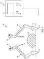
- FIG. 6illustrates an embodiment of a robotic surgical system 600 similar to robotic surgical system 300 in FIG. 1 .
- the robotic surgical system 600can include a wireless interface 12 at tool assembly 10 to allow for communication between tool assembly 10 and wireless interface 32 at control system 30 .
- the robotic surgical system 600includes robotic arm 20 configured to releasably couple to tool assembly 10 . In some embodiments, such as shown in FIG. 6 , more than one robotic arm 20 and/or more than one tool assembly 10 may be included in robotic surgical system 600 .
- the tool assembly 10When robotic arm 20 is coupled to the tool assembly 10 , the tool assembly 10 is both electrically and mechanically coupled to the robotic arm 20 .
- the tool assembly 10is powered by the robotic arm 20 via electrical connectors associated with the tool assembly 10 and robotic arm 20 , which are mated when the tool assembly 10 is coupled to robotic arm 20 .
- the tool assembly 10can be uncoupled from robotic arm 20 thereby mechanically and electrically disconnecting the tool assembly 10 from the robotic arm.
- Such electrical disconnectionincludes disconnecting the electrical connectors supplying power (and possibly control and status information) from the robotic arm 20 to the tool assembly 10 .
- the tool assembly 10can be powered by a battery 13 , as described below.
- tool assembly 10While powered by battery 13 , tool assembly 10 does not shut down and can be used manually, such as by a surgeon after being coupled to a handle (not shown). Tool assembly 10 can also be re-coupled to either the same robotic arm 20 or coupled to a different robotic arm 20 .
- the wireless tool interface of the tool assembly 10includes a transducer, such as an ultrasonic transducer that produces ultrasonic energy, or a radio frequency generator that produces radio frequency energy.
- a transducersuch as an ultrasonic transducer that produces ultrasonic energy, or a radio frequency generator that produces radio frequency energy.
- Such energycan be applied to a patient 312 by the tool assembly 10 for assisting with a surgical procedure (e.g., cutting tissue).
- Tool assembly 10can include a generator that generates signals to drive the ultrasonic transducer and/or a generator that generates radio frequency energy. Calibration data may be needed to drive the ultrasonic transducer with one or more predefined amplitudes and/or frequencies. See FIGS. 8 and 9 for further description of an ultrasonic generator, an ultrasonic transducer, and radio frequency end effector.
- the wireless interface 12 at tool assembly 10is configured to communicate with wireless interface 32 at control system 30 .
- Wireless interfaces 12 and/or 32can comply with Bluetooth, Bluetooth low-energy, WiFi, Zigbee, or any other wireless standard, or any proprietary wireless interface.
- communication protocolsin addition to the wireless communication techniques noted above can also be used. Examples include acoustic communication (such as ultrasonic communication), optical data links, and magnetic data transfer.
- Tool assembly 10can send status information to control system 30 .
- the status informationcan include data about the usage of the tool assembly, such as a number of uses or a number of cuts made by an end effector that is included in the tool assembly, a quantity of time that the tool assembly has been used, and a lifetime or charge status of a battery included in tool assembly 10 A, other status information can also include fault detection recording and tool position when a tool is removed from a robotic arm.
- calibration information used by an energy generator to drive a transducer in tool assembly 10 Ais sent or received via the wireless interface. See also the description below of FIGS. 8-11 for additional description of the calibration information.
- the tool assembly 10includes one or more sensors for determining either a position or movement of the tool assembly 10 .
- the tool assembly 10can include one or more inertial sensors, such as an accelerometer (single or multi-axis), a gyroscope, and/or one or more relative position sensors such as a magnetic sensor (single, or multi-dimensional). Data from one or more of such sensors can be processed at tool assembly 10 A or sent via the wireless interface to control system 30 for processing. Processing the sensor data can determine the position of the tool assembly. For example, processing the sensor data can determine that tool assembly 10 A is located at a position that is at the end of robotic arm 20 B.
- control system 30determines that the tool assembly 10 A has been moved to robotic arm 20 B.
- the sensor datacan be used to determine that the tool assembly 10 has moved a predetermined distance in a predetermined direction. For example, processing the sensor data can determine that the tool assembly 10 has moved approximately 32.1 inches in a direction pointing from the end of the robotic arm 20 . From the distance and direction, control system 30 can determine that the tool assembly 10 has been moved to robotic arm 20 . In some example embodiments, when a tool assembly 10 A is removed from one robotic arm 20 , and attached to another robotic arm 20 , the tool assembly 10 has been “handed-off” to the other robotic arm 20 .
- the robotic arm 20can include a transfer arm that is configured to provide a second attachment point to which tool assembly 10 can releasably couple.
- the tool assembly 10can include one or more attachment points to the transfer arm.
- the transfer armcan latch on to the tool assembly while the robotic arm is still attached to the tool assembly 10 .
- the robotic arm 20can uncouple from the tool assembly 10 and the transfer arm can remain connected to the tool assembly 10 .
- the same or a different robotic arm 20can couple to the tool assembly 10 and the transfer arm can thereafter uncouple from the tool assembly 10 .
- a first robotic armcan be coupled to the tool assembly at a first attachment point of the tool assembly and a second robotic arm can be coupled to a second attachment point of the tool assembly. The first robotic arm can then uncouple from the tool assembly thereby leaving the second robotic arm coupled to the tool assembly.
- Some embodimentscan include interchangeable shafts in the transfer arm. Exemplary robotic surgical systems are described in U.S. Pat. No. 8,931,682, entitled “Robotically-Controlled Shaft based Rotary Drive Systems for Surgical Instruments” and U.S. Patent Application Publication No. 2014/005718, entitled Multi-Functional Powered Surgical Device with External Dissection Features,” both of which are incorporated herein by reference in the entirety.
- tool assembly 10can include a battery 13 .
- the battery 13can supply power to the tool assembly 10 after the tool assembly 10 has been removed from the robotic arm.
- the battery 13can power a processor, memory, sensors, and/or the wireless interface included in the tool assembly 10 .
- the battery 13can enable an endocutter to be operated when unattached from a robotic arm 20 .
- the tool assembly 10may include location and/or movement sensors. When tool assembly 10 is detached from robotic arm 20 battery 13 powers the sensors 14 , the wireless interface 13 , and a processor and memory 15 .
- an endocutter tool assemblycan be operated by a surgeon while detached from the robotic arm.
- the endocutter tool assemblycan be attached to the same or a different robotic arm.
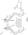
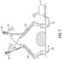
- FIG. 7illustrates tool assemblies 10 A and 10 B that can each include the features of tool assembly 10 in FIG. 6 including wireless interface 12 , battery 13 , sensors 14 , and/or processor and memory 15 .
- FIG. 7illustrates decoupling a tool assembly 10 A from a first robotic arm 20 B and attaching the tool assembly 10 A to a second robotic arm 20 A, or the first robotic arm 20 B at a later time.
- the tool assembly 10 Amaintains a wireless connection to the control system 30 .
- the tool assembly 10 Acan be powered by the battery 13 included in the tool assembly 10 as described in FIG. 6 and FIGS.
- the above-described location/movement sensors 14can generate data that can be processed by processor and memory 15 at the tool assembly 10 A or processed at control system 30 to periodically or intermittently determine the location of the tool assembly.
- a surgeoncan operate tool assembly 10 A while the tool assembly 10 A is detached from robotic arms 20 B and 20 A. While detached, the tool assembly 10 A can be powered by the battery 13 internal to tool assembly 10 A or by a battery internal to a handle that can be releasably attached to tool assembly 10 A as detailed with respect to FIGS. 10 and 11 .
- Tool assembly 10 Acan maintain wireless communication with control system 30 while attached to a robotic arm 20 B and while detached from a robotic arm 20 B and used manually by a surgeon. Tool assembly 10 A can be attached to a handle as described in FIGS. 10-12 for use by the surgeon.
- the tool assembly 10 Acan be attached to robotic arm 20 B and tool assembly 10 B can be attached to robotic arm 20 A.
- Tool assembly 10 Acan be powered by connectors in tool assembly 10 A and robotic arm 20 B that are mated when the tool assembly is attached.
- Tool assembly 10 Bcan be powered by connectors in tool assembly 10 B and robotic arm 20 A that are mated when the tool assembly is attached.
- tool assembly 10 Ais removed from robotic arm 20 B. After removal from robotic arm 20 B, tool assembly 10 A remains powered by the battery included in tool assembly 10 A.
- the above-described location/movement sensorscan generate data that can be processed at the tool assembly or control system to periodically or intermittently determine the location of the tool assembly.
- the generated data and/or processed location/movementcan be wirelessly transmitted to control system 30 .
- Tool assembly 10 Acan be removed from robotic arm 20 B and attached to robotic arm 20 A.
- tool assembly 10 Bcan removed from robotic arm 20 A, data processed/transmitted, and 10 B is attached to robotic arm 20 B.
- a robotic surgical armcan include a modular attachment containing motors to drive an end effector.
- the modular attachmentmay include an ultrasonic generator to drive an ultrasonic transducer to produce ultrasonic energy to apply between the jaws of the end effector.
- the modular attachmentmay also include a radio frequency generator to produce radio frequency energy to apply between the jaws of the end effector.
- the jaws of the end effectorare or include electrodes that conduct the radio frequency energy to patient tissue disposed therebetween.
- the modular attachmentcan include modular components such as a modular shaft that can include the ultrasonic transducer, nonvolatile memory, and/or a power source.
- the non-volatile memorycan allow the modular shaft to be attached to one robotic arm and then moved to another robotic arm without restarting or recalibrating the ultrasonic transducer.
- the power sourcecan allow the modular shaft to communicate wirelessly with the robotic while attached to a robotic arm and after the modular shaft is detached from the robotic arm.
- the modular shaftcan also be moved from a robotic arm to a handle manually controlled by a surgeon and back again to the robotic arm.
- FIG. 8Aillustrates an embodiment of a puck assembly 110 that can be included in a tool assembly, such as tool assembly 10 A in FIG. 7 and/or tool assembly 10 in FIG. 6 .
- FIG. 8Billustrates an end-view of puck assembly 110 .
- Puck assembly 110is a removable and replaceable module that can be coupled to a robotic arm 130 .
- a puck assembly 110 with ultrasonic transducer 122can be removed and replaced with a puck with a radio frequency capability (not shown in FIG. 8A ) and an ultrasonic transducer.
- Ultrasonic transducer 122can be disposable.
- ultrasonic transducer 122can be used once, or used in one procedure, or on one patient, and then disposed and not used again.
- Puck assembly 110can include a tool driver 120 , circuit boards 114 and/or 116 , battery 118 , and motor 117 for shaft rotation, motor 119 for jaw clamping, and/or 121 .
- Circuit boards 114 and/or 116can produce electrical signals to drive an ultrasonic transducer, or to produce radio frequency energy that can assist in cauterizing blood vessels and tissue.
- Motors 117 , 119 , and/or 121can control opening and closing of the end effector, rotation of the end effector, firing, articulation, etc.
- Puck assembly 110can include a liquid crystal display (LCD) 112 to provide status and control information at a robotic arm.
- LCDliquid crystal display
- Puck assembly 110can include a wired or wireless interface to communicate with a robotic control system.
- a wireless interfacecan receive commands from a user side portion of a robotic system and/or send status information to the user side portion of the robotic system (see FIG. 1 ).
- Puck assembly 110can include a processor and memory, motors, LCD display, ultrasonic and/or radio frequency energy generator, and a wireless interface to communicate with the user side portion.
- Wiring 102 from robotic arm 130can carry power to puck assembly 110 .
- wiring 102can also carry status and control information between puck 110 and a control system at the user side of the robotic system.
- poweris supplied through wiring 102 and status and control information is exchanged via a wireless interface.
- the wireless interfacemay comply with any standard such as Bluetooth, Bluetooth low-energy, WiFi, Zigbee, or any other standard, or any proprietary wireless interface, as discussed above.
- Puck assembly 110can include a non-volatile memory on one or more of circuit boards 114 and/or 116 .
- the non-volatile memorycan store status and configuration information for puck 110 that can include calibration data for an ultrasonic generator.
- calibration informationcan be stored in non-volatile memory related to causing the particular ultrasonic transducer installed in tool driver 120 to produce one or more predefined ultrasonic frequencies at one or more predefined amplitudes.
- Ultrasonic transducers of the same type that are paired with a waveguidecan behave differently to stimulus applied by an ultrasonic generator. These differences result in calibration information that is used to produce the predefined ultrasonic frequencies at the predefined amplitudes.
- Configuration information stored in memorycan include usage information related to tool driver 120 and/or puck 110 .
- Puck 110can include battery 118 .
- puck 110can be moved from one arm of a robotic system to another arm of the robotic system without powering down puck 110 .
- Battery 118can provide power to circuit boards 114 and/or 116 .
- battery 118can power circuit boards 116 , 118 but can or can not power the motors, ultrasonic generator, or radio frequency generator.
- battery 118can provide power to the processor, memory, and a wireless interface. Wireless communications can continue while the puck is being moved and until power is connected again by wire at the other robotic arm.
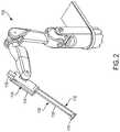
- FIG. 9illustrates a tool driver 210 releasably coupled to modular shaft 250 .
- Tool driver 210 and modular shaft 250may be included in puck assembly 110 of FIGS. 8A and 8B and/or tool assembly 10 A of FIG. 7 and/or tool assembly 10 of FIG. 6 .
- Modular shaft 250can be attached to tool driver 210 , and can be detached from tool driver 210 .
- Modular shaft 250can be detached from one tool driver 210 and attached to another tool driver 210 .
- Tool driver 210may include one or more motors 238 powering rotating drivers 230 (labeled 1 , 2 , and 3 ). Rotating drivers 230 can detachably interface with modular shaft 250 .
- Tool driver 210can include connector 228 A that mates with connector 228 B on modular shaft 250 .
- rotating drivers 230can cause rotation of spur gears 212 (labeled a, b, and c) inside modular shaft 250 .
- Attaching modular shaft 250 to tool driver 210causes an electrical connection to be made between connectors 228 A and 228 B that can supply power to modular shaft 250 and can and provide a wired interface for communication between the modular shaft 250 and tool driver 210 .
- Modular shaft 250can include an ultrasonic transducer such as lateral ultrasonic transducer 214 . Lateral ultrasonic transducer 214 can be coupled to waveguide 236 to guide ultrasonic energy to clamp jaw 218 . Modular shaft 250 can include worm gear 220 to open and close clamp jaw 218 . Modular shaft can also include spur gears 224 and/or 212 . Modular shaft 250 can include processor 222 and can include memory and/or nonvolatile memory. The memory and/or nonvolatile memory can store configuration and/or calibration information.
- the non-volatile memorycan store calibration information related to the ultrasonic transducer 214 , usage information related to ultrasonic transducer 214 (number of times used, total time used, manufacture date etc.), usage information related to modular shaft 250 , clamp jaw 218 , or tool driver 210 , or battery charge status or battery lifetime information for battery 232 .
- An ultrasonic generator 252 Bcan be included in modular shaft 250 or can be included in tool driver 210 to generate stimulus to cause the ultrasonic transducer 214 to produce a predefined ultrasonic output.
- Modular shaft 250can include battery 232 that can power one or more portions of modular shaft 250 when modular shaft 250 is disconnected from tool driver 210 as described above.
- Modular shaft 250can include spur gear 216 to rotate an outer shaft and a clamp jaw 218 .
- Modular shaft 250can include worm gear assembly 220 to open and close clamp jaw 218 .
- Modular shaft 250can include spur gear assembly 224 to rotate inner housing 254 .
- control and status informationcan flow through connectors 228 A and 228 B.
- control and status informationcan be exchanged between modular shaft 250 and tool driver 210 via a wireless interface such as the wireless interfaces described above.
- an ultrasonic generator 252 Acan be included in tool driver 210 and calibration and/or configuration information for the lateral ultrasonic transducer 214 can be stored in memory or non-volatile memory at modular shaft 250 .
- the ultrasonic generator 252 A in tool driver 210is detached from modular shaft 250 .
- the configuration and calibration information needed to drive lateral ultrasonic transducer 214can be retrieved by the ultrasonic driver in the newly attached tool driver.
- the calibration and/or configuration informationcan be retrieved via the wireless interface described above or via electrical connection through connectors 228 A and 228 B.
- FIGS. 10A and 10Bdepict an example of a modular shaft that is swappable between a robotic arm at 410 ( FIG. 10A ) and a handle at 440 ( FIG. 10B ).
- Some aspects of modular shaft 416are described with respect to FIGS. 8 and 9 .
- modular shaft 416is attached to tool driver 412 , which is attached to robotic arm 320 .
- An ultrasonic driver(also referred to herein as an ultrasonic generator) can be included in tool driver 412 .
- a radio frequency generatorcan be included in tool driver 412 , alternatively or in addition to the ultrasonic generator.
- Tool driver 412can include one or more motors.
- Modular shaft 416can include one or more of a non-volatile memory, processor, and/or battery. In some embodiments, the non-volatile memory can store calibration and configuration information as described above related to modular shaft 416 .
- Modular shaft 416can be detached from tool driver 412 and attached to handle 442 , as depicted at 440 . Modular shaft 416 can also be detached from handle 442 and attached to tool driver 412 , as depicted at 410 .
- Handle 442can include ultrasonic generator 448 , radio frequency generator 450 , motors 452 , and/or LCD screen 446 .
- Handle 442can include a battery to power handle 442 , or handle 442 can include a cable that supplies power.
- Handle 442can include a wired or wireless status and control interface.
- Handle 442can include controls 458 to open/close clamp jaw 462 , a fire energy control 456 to cause ultrasonic/radio frequency energy to be applied/removed from clamp jaw 462 , and/or shaft rotation control 454 .
- the calibration and/or configuration information stored in the non-volatile memory in modular shaft 416can be transferred to handle 442 .
- the transfer of configuration and calibration informationcan allow the modular shaft 416 to be moved to the handle more quickly without requiring initialization and/or recalibration of the ultrasonic transducer paired with a new ultrasonic generator in the handle.
- the modular shaftcan be similarly moved from the handle to the robotic arm.
- FIGS. 11A and 11Bdepict another example of a modular tool that is swappable between a robotic arm and a handle.
- a hand operated tool at 500 in FIG. 11Aincludes tool driver 510 , end effector 512 , motors 520 , and handle 530 .
- Handle 530can include a battery, a processor, an ultrasonic generator and/or a radio frequency generator.
- Tool driver 510can include an ultrasonic transducer and/or radio frequency generator.
- Tool driver 510can include a non-volatile memory that can store configuration and calibration data related to tool driver 510 , the generator(s) in the tool driver, and/or end effector 512 .
- Tool driver 510 and end effector 512can be detached from handle 530 and attached to robotic arm 560 without requiring recalibration or restart of tool driver 510 as described above with respect to FIGS. 1-6 .
- moving the tool driver and end effector 512 from handle 530 to robotic arm 560 , or moving the tool driver 510 and end effector 512 from robotic arm 560 to handle 530can be performed without recalibration or restart of the tool driver 510 .
- Moving the tool driver 510 without restart or recalibrationcan be referred to as “hot-swapping.”
- a wireless interface included in tool driver 510 and handle 530can allow calibration and configuration information to be shared between the tool driver 510 and handle 530 .
- the wireless interface included in tool driver 510 and robotic arm 560can allow calibration and configuration information to be shared between the tool driver 510 and robotic arm 560 .
- Robotic arm 560can include contacts 562 to supply power to tool driver 510 .
- tool driver 510 , end effector 512 , and handle 530can be attached to robotic arm 560 without removal of the handle 530 .
- handle 440 in FIG. 10can be handle 530 .
- FIG. 12Aillustrates a surgical tool assembly 650 attached to robotic arm 640 .
- the tool assembly 650includes a tool driver 610 , an adapter 620 , and a modular shaft 625 .
- puck 615is included as part of robotic arm 640 .
- Puck 615can include sterile barrier 617 .
- Tool driver 610can include separable pieces, including adapter 620 and modular shaft 625 , and end effector 642 .
- FIG. 12Billustrates an expanded view of the tool assembly 650 shown in FIG. 12A .
- Modular shaft 625can include an end effector 642 , gears 643 for actuating/rotating the end effector, and a non-volatile memory 644 .
- the non-volatile memory 644can store information related to the status of the modular shaft 625 such as number of uses, times and dates of when the shaft was used, and/or location information relating to where the shaft was used.
- location informationcan include one or more of: on which robotic arm the shaft was used, which surgical robot identified by a serial number, as well as the known physical location of the surgical robot.
- the information stored in non-volatile memorycan be transferred via wired electrical connections that are connected when modular shaft 625 is attached to adapter 620 .
- the status information of modular shaft 625can be transferred to tool driver 610 when adapter 620 (with modular shaft attached to the adapter) is attached to tool assembly 650 .
- modular shaft 625 and/or adapter 620can include a wireless interface 645 and a battery 646 that can provide the status information to adapter 620 and/or tool driver 610 when modular shaft 625 is attached or detached from adapter 620 .
- FIG. 12Cillustrates modular shaft 625 removed from the adapter 620 in FIGS. 12A and 12B , and attached to handle 630 .
- Handle 630can include a connector 647 to transfer status information from the non-volatile memory 644 in the modular shaft to the handle 630 .
- handle 630can include a wireless interface 645 to receive status information from modular shaft 625 wirelessly.
- FIG. 13Adepicts examples of modular transducers and modular shafts that can be attached to a tool assembly 700
- FIG. 13Bdepicts examples of modular tool drivers that can be attached to a tool assembly 700
- Tool assembly 700can include a transducer selected from a set of transducers, a tool driver selected from a set of tool drivers, and a shaft/nozzle selected from a set of shafts/nozzles.
- transducersinclude ultrasonic transducers 701 , 702 , combination transducer 703 including an ultrasonic transducer and a radio frequency end effector combination 704 , and radio frequency end effector 705 .
- tool driversinclude ultrasonic and/or radio frequency tool driver 711 and stapling tool driver 712 .
- shafts/nozzlesexamples include ultrasonic shaft 721 , combination shaft 722 including ultrasonic shaft and radio frequency shaft, radio frequency shaft 723 with opposable jaw, radio frequency shaft 724 including an I-blade, linear stapler 725 , shaft coupler 726 , and circular stapler 727 .
- FIG. 13Bdepicts examples of modular tool drivers.
- a modular shaft adapter 740can provide for the attachment to tool assembly 700 of hand-held tool drivers including clip applier 731 and stitching end effectors 732 , 733 .
- wireless communications between a tool driver (or tool assembly) and a control systemreduces the number of wires required to interface between a robotic arm and tool driver which improves the reliability the wired interface and improves the reliability of communications between the tool driver and control system.
- a tool driver with wireless communications and a battery for powerallows for communications when the tool driver is detached from a robotic arm when being moved from one robotic arm to another or being used manually by a surgeon.
- Communications between modular componentsallows for configuration, usage, and calibration information to be exchanged between the modular components which provides for better automation of the operating room and improved data integrity over data recorded manually by surgical staff.
- Tool drivers with modular adaptersimprove the flexibility and number of uses a surgical robot may be used which in turn reduces the cost of robotic assisted surgeries.
- the degrees of freedom of a systemare the number of independent variables that uniquely identify its pose or configuration.
- the set of Cartesian degrees of freedomis usually represented by the three translational or position variables, e.g., surge, heave, and sway, and by the three rotational or orientation variables, e.g., Euler angles or roll, pitch, and yaw, that describe the position and orientation of a component of a surgical system with respect to a given reference Cartesian frame.
- the three translational or position variablese.g., surge, heave, and sway
- the three rotational or orientation variablese.g., Euler angles or roll, pitch, and yaw
- the term “surge”refers to forward and backward movement
- the term “heave”refers to movement up and down
- the term “sway”refers to movement left and right.
- the rotational terms“roll” refers to tilting side to side
- “pitch”refers to tilting forward and backward
- “yaw”refers to turning left and right.
- each of the translation termsrefers to movement along one of the three axes in a Cartesian frame
- each of the rotational termsrefers to rotation about one of the three axes in a Cartesian frame.
- the number of degrees of freedomis at most six, a condition in which all the translational and orientation variables are independently controlled, the number of joint degrees of freedom is generally the result of design choices that involve considerations of the complexity of the mechanism and the task specifications.
- the number of independently controlled jointsis equal to the degree of mobility for an end effector.
- the end effectorwill have an equal number of degrees of freedom in Cartesian space that will correspond to a combination of translational and rotational motions. Accordingly, the number of degrees of freedom can be more than, equal to, or less than six.
- forwardrefers to an end of the surgical system that is closest to the distal end of the input tool, and when in use in a surgical procedure, to the end disposed within a patient's body.
- rearwardrefers to an end of the surgical system farthest from the distal end of the input tool, and when in use, generally to the end farther from the patient.
- spatially relative termse.g., “superior,” “inferior,” “beneath,” “below,” “lower,” “above,” “upper,” “rearward,” “forward,” etc.
- These spatially relative termsare intended to encompass different positions and orientations of the device in use or operation in addition to the position and orientation shown in the figures. For example, if the device in the figures is turned over, elements described as “inferior to” or “below” other elements or features would then be “superior to” or “above” the other elements or features.
- An end effectoris the part of a surgical instrument or assembly that performs a specific surgical function, e.g., forceps/graspers, needle drivers, scissors, electrocautery hooks, staplers, clip appliers/removers, suction tools, irrigation tools, etc. Any end effector can be utilized with the surgical systems described herein. Further, in exemplary embodiments, an end effector can be configured to be manipulated by a user input tool.
- the input toolcan be any tool that allows successful manipulation of the end effector, whether it be a tool similar in shape and style to the end effector, such as an input tool of scissors similar to end effector scissors, or a tool that is different in shape and style to the end effector, such as an input tool of a glove dissimilar to end effector graspers, and such as an input tool of a joystick dissimilar to end effector graspers.
- the input toolcan be a larger scaled version of the end effector to facilitate ease of use.
- Such a larger scale input toolcan have finger loops or grips of a size suitable for a user to hold.
- the end effector and the input toolcan have any relative size.
- a slave tool, e.g., a surgical instrument, of the surgical systemcan be positioned inside a patient's body cavity through an access point in a tissue surface for minimally invasive surgical procedures.
- cannulassuch as trocars are used to provide a pathway through a tissue surface and/or to prevent a surgical instrument or guide tube from rubbing on patient tissue.
- Cannulascan be used for both incisions and natural orifices.
- Some surgical proceduresrequire insufflation, and the cannula can include one or more seals to prevent excess insufflation gas leakage past the instrument or guide tube.
- the cannulacan have a housing coupled thereto with two or more sealed ports for receiving various types of instruments besides the slave assembly.
- any of the surgical system components disclosed hereincan have a functional seal disposed thereon, therein, and/or therearound to prevent and/or reduce insufflation leakage while any portion of the surgical system is disposed through a surgical access port, such as a cannula.
- the surgical systemscan also be used in open surgical procedures.
- a surgical access pointis a point at which the slave tool enters a body cavity through a tissue surface, whether through a cannula in a minimally invasive procedure or through an incision in an open procedure.
- the systems, devices, and methods disclosed hereincan be implemented using one or more computer systems, which may also be referred to herein as digital data processing systems and programmable systems.
- One or more aspects or features of the subject matter described hereincan be realized in digital electronic circuitry, integrated circuitry, specially designed application specific integrated circuits (ASICs), field programmable gate arrays (FPGAs) computer hardware, firmware, software, and/or combinations thereof.
- ASICsapplication specific integrated circuits
- FPGAsfield programmable gate arrays
- These various aspects or featurescan include implementation in one or more computer programs that are executable and/or interpretable on a programmable system including at least one programmable processor, which can be special or general purpose, coupled to receive data and instructions from, and to transmit data and instructions to, a storage system, at least one input device, and at least one output device.
- the programmable system or computer systemmay include clients and servers.
- a client and serverare generally remote from each other and typically interact through a communication network. The relationship of client and server arises by virtue of computer programs running on the respective computers and having a client-server relationship to each other.
- the computer programswhich can also be referred to as programs, software, software applications, applications, components, or code, include machine instructions for a programmable processor, and can be implemented in a high-level procedural language, an object-oriented programming language, a functional programming language, a logical programming language, and/or in assembly/machine language.
- machine-readable mediumrefers to any computer program product, apparatus and/or device, such as for example magnetic discs, optical disks, memory, and Programmable Logic Devices (PLDs), used to provide machine instructions and/or data to a programmable processor, including a machine-readable medium that receives machine instructions as a machine-readable signal.
- machine-readable signalrefers to any signal used to provide machine instructions and/or data to a programmable processor.
- the machine-readable mediumcan store such machine instructions non-transitorily, such as for example as would a non-transient solid-state memory or a magnetic hard drive or any equivalent storage medium.
- the machine-readable mediumcan alternatively or additionally store such machine instructions in a transient manner, such as for example as would a processor cache or other random access memory associated with one or more physical processor cores.
- one or more aspects or features of the subject matter described hereincan be implemented on a computer having a display device, such as for example a cathode ray tube (CRT) or a liquid crystal display (LCD) or a light emitting diode (LED) monitor for displaying information to the user and a keyboard and a pointing device, e.g., a mouse, a trackball, etc., by which the user may provide input to the computer.
- a display devicesuch as for example a cathode ray tube (CRT) or a liquid crystal display (LCD) or a light emitting diode (LED) monitor for displaying information to the user and a keyboard and a pointing device, e.g., a mouse, a trackball, etc.
- CTRcathode ray tube
- LCDliquid crystal display
- LEDlight emitting diode
- a keyboard and a pointing devicee.g., a mouse, a trackball, etc.
- Other kinds of devices
- feedback provided to the usercan be any form of sensory feedback, such as for example visual feedback, auditory feedback, or tactile feedback; and input from the user may be received in any form, including, but not limited to, acoustic, speech, or tactile input.
- Other possible input devicesinclude, but are not limited to, touch screens or other touch-sensitive devices such as single or multi-point resistive or capacitive trackpads, voice recognition hardware and software, optical scanners, optical pointers, digital image capture devices and associated interpretation software, and the like.
- FIG. 15illustrates one exemplary embodiment of a computer system 1300 .
- the computer system 1300includes one or more processors 1302 which can control the operation of the computer system 1300 .
- processors 1302are also referred to herein as “controllers.”
- the processor(s) 1302can include any type of microprocessor or central processing unit (CPU), including programmable general-purpose or special-purpose microprocessors and/or any one of a variety of proprietary or commercially available single or multi-processor systems.
- the computer system 1300can also include one or more memories 1304 , which can provide temporary storage for code to be executed by the processor(s) 1302 or for data acquired from one or more users, storage devices, and/or databases.
- the memory 1304can include read-only memory (ROM), flash memory, one or more varieties of random access memory (RAM) (e.g., static RAM (SRAM), dynamic RAM (DRAM), or synchronous DRAM (SDRAM)), and/or a combination of memory technologies.
- ROMread-only memory
- flash memoryone or more varieties of random access memory (RAM) (e.g., static RAM (SRAM), dynamic RAM (DRAM), or synchronous DRAM (SDRAM)), and/or a combination of memory technologies.
- RAMrandom access memory
- SRAMstatic RAM
- DRAMdynamic RAM
- SDRAMsynchronous DRAM
- the various elements of the computer system 1300can be coupled to a bus system 1312 .
- the illustrated bus system 1312is an abstraction that represents any one or more separate physical busses, communication lines/interfaces, and/or multi-drop or point-to-point connections, connected by appropriate bridges, adapters, and/or controllers.
- the computer system 1300can also include one or more network interface(s) 1306 , one or more input/output (IO) interface(s) 1308 , and one or more storage device(s) 110 .
- IOinput/output
- the network interface(s) 1306can enable the computer system 1300 to communicate with remote devices, e.g., other computer systems, over a network, and can be, for non-limiting example, remote desktop connection interfaces, Ethernet adapters, and/or other local area network (LAN) adapters.
- the IO interface(s) 1308can include one or more interface components to connect the computer system 1300 with other electronic equipment.
- the IO interface(s) 1308can include high speed data ports, such as universal serial bus (USB) ports, 1394 ports, Wi-Fi, Bluetooth, etc.
- the computer system 1300can be accessible to a human user, and thus the IO interface(s) 1308 can include displays, speakers, keyboards, pointing devices, and/or various other video, audio, or alphanumeric interfaces.
- the storage device(s) 1310can include any conventional medium for storing data in a non-volatile and/or non-transient manner. The storage device(s) 1310 can thus hold data and/or instructions in a persistent state, i.e., the value(s) are retained despite interruption of power to the computer system 1300 .
- the storage device(s) 1310can include one or more hard disk drives, flash drives, USB drives, optical drives, various media cards, diskettes, compact discs, and/or any combination thereof and can be directly connected to the computer system 1300 or remotely connected thereto, such as over a network.
- the storage device(s)can include a tangible or non-transitory computer readable medium configured to store data, e.g., a hard disk drive, a flash drive, a USB drive, an optical drive, a media card, a diskette, a compact disc, etc.
- FIG. 15can be some or all of the elements of a single physical machine. In addition, not all of the illustrated elements need to be located on or in the same physical machine.
- Exemplary computer systemsinclude conventional desktop computers, workstations, minicomputers, laptop computers, tablet computers, personal digital assistants (PDAs), mobile phones, and the like.
- PDAspersonal digital assistants
- the computer system 1300can include a web browser for retrieving web pages or other markup language streams, presenting those pages and/or streams (visually, aurally, or otherwise), executing scripts, controls and other code on those pages/streams, accepting user input with respect to those pages/streams (e.g., for purposes of completing input fields), issuing HyperText Transfer Protocol (HTTP) requests with respect to those pages/streams or otherwise (e.g., for submitting to a server information from the completed input fields), and so forth.
- the web pages or other markup languagecan be in HyperText Markup Language (HTML) or other conventional forms, including embedded Extensible Markup Language (XML), scripts, controls, and so forth.
- the computer system 1300can also include a web server for generating and/or delivering the web pages to client computer systems.
- the computer system 1300can be provided as a single unit, e.g., as a single server, as a single tower, contained within a single housing, etc.
- the single unitcan be modular such that various aspects thereof can be swapped in and out as needed for, e.g., upgrade, replacement, maintenance, etc., without interrupting functionality of any other aspects of the system.
- the single unitcan thus also be scalable with the ability to be added to as additional modules and/or additional functionality of existing modules are desired and/or improved upon.
- a computer systemcan also include any of a variety of other software and/or hardware components, including by way of non-limiting example, operating systems and database management systems. Although an exemplary computer system is depicted and described herein, it will be appreciated that this is for sake of generality and convenience. In other embodiments, the computer system may differ in architecture and operation from that shown and described here.
- the devices disclosed hereincan also be designed to be disposed of after a single use, or they can be designed to be used multiple times. In either case, however, the device can be reconditioned for reuse after at least one use. Reconditioning can include any combination of the steps of disassembly of the device, followed by cleaning or replacement of particular pieces and subsequent reassembly. In particular, the device can be disassembled, and any number of the particular pieces or parts of the device can be selectively replaced or removed in any combination. Upon cleaning and/or replacement of particular parts, the device can be reassembled for subsequent use either at a reconditioning facility, or by a surgical team immediately prior to a surgical procedure.
- reconditioning of a devicecan utilize a variety of techniques for disassembly, cleaning/replacement, and reassembly. Use of such techniques, and the resulting reconditioned device, are all within the scope of the present application.
- components of the invention described hereinwill be processed before use.
- a new or used instrumentis obtained and if necessary cleaned.
- the instrumentcan then be sterilized.
- the instrumentis placed in a closed and sealed container, such as a plastic or TYVEK bag.
- the container and instrumentare then placed in a field of radiation that can penetrate the container, such as gamma radiation, x-rays, or high energy electrons.
- the radiationkills bacteria on the instrument and in the container.
- the sterilized instrumentcan then be stored in the sterile container.
- the sealed containerkeeps the instrument sterile until it is opened in the medical facility.
- the deviceis sterilized. This can be done by any number of ways known to those skilled in the art including beta or gamma radiation, ethylene oxide, steam, and a liquid bath (e.g., cold soak).
- a liquid bathe.g., cold soak.
- An exemplary embodiment of sterilizing a device including internal circuitryis described in more detail in U.S. Pat. No. 8,114,345, filed Feb. 8, 2008 and entitled “System And Method Of Sterilizing An Implantable Medical Device.” It is preferred that a device, if implanted, is hermetically sealed. This can be done by any number of ways known to those skilled in the art.
Landscapes
- Engineering & Computer Science (AREA)
- Health & Medical Sciences (AREA)
- Life Sciences & Earth Sciences (AREA)
- Surgery (AREA)
- Robotics (AREA)
- Public Health (AREA)
- Biomedical Technology (AREA)
- Heart & Thoracic Surgery (AREA)
- Medical Informatics (AREA)
- Molecular Biology (AREA)
- Animal Behavior & Ethology (AREA)
- General Health & Medical Sciences (AREA)
- Nuclear Medicine, Radiotherapy & Molecular Imaging (AREA)
- Veterinary Medicine (AREA)
- Mechanical Engineering (AREA)
- Physics & Mathematics (AREA)
- Human Computer Interaction (AREA)
- Computer Networks & Wireless Communication (AREA)
- Electromagnetism (AREA)
- Oral & Maxillofacial Surgery (AREA)
- Pathology (AREA)
- Plasma & Fusion (AREA)
- Otolaryngology (AREA)
- Manipulator (AREA)
Abstract
Description
Claims (14)
Priority Applications (3)
| Application Number | Priority Date | Filing Date | Title |
|---|---|---|---|
| US15/238,022US10993760B2 (en) | 2016-08-16 | 2016-08-16 | Modular surgical robotic tool |
| PCT/US2017/046453WO2018034965A1 (en) | 2016-08-16 | 2017-08-11 | Modular surgical robotic tools |
| US17/155,461US12016611B2 (en) | 2016-08-16 | 2021-01-22 | Modular surgical robotic tool |
Applications Claiming Priority (1)
| Application Number | Priority Date | Filing Date | Title |
|---|---|---|---|
| US15/238,022US10993760B2 (en) | 2016-08-16 | 2016-08-16 | Modular surgical robotic tool |
Related Child Applications (1)
| Application Number | Title | Priority Date | Filing Date |
|---|---|---|---|
| US17/155,461ContinuationUS12016611B2 (en) | 2016-08-16 | 2021-01-22 | Modular surgical robotic tool |
Publications (2)
| Publication Number | Publication Date |
|---|---|
| US20180049794A1 US20180049794A1 (en) | 2018-02-22 |
| US10993760B2true US10993760B2 (en) | 2021-05-04 |
Family
ID=59687044
Family Applications (2)
| Application Number | Title | Priority Date | Filing Date |
|---|---|---|---|
| US15/238,022Active2039-08-19US10993760B2 (en) | 2016-08-16 | 2016-08-16 | Modular surgical robotic tool |
| US17/155,461Active2037-04-08US12016611B2 (en) | 2016-08-16 | 2021-01-22 | Modular surgical robotic tool |
Family Applications After (1)
| Application Number | Title | Priority Date | Filing Date |
|---|---|---|---|
| US17/155,461Active2037-04-08US12016611B2 (en) | 2016-08-16 | 2021-01-22 | Modular surgical robotic tool |
Country Status (2)
| Country | Link |
|---|---|
| US (2) | US10993760B2 (en) |
| WO (1) | WO2018034965A1 (en) |
Cited By (1)
| Publication number | Priority date | Publication date | Assignee | Title |
|---|---|---|---|---|
| US12016611B2 (en) | 2016-08-16 | 2024-06-25 | Cilag Gmbh International | Modular surgical robotic tool |
Families Citing this family (314)
| Publication number | Priority date | Publication date | Assignee | Title |
|---|---|---|---|---|
| US9060770B2 (en) | 2003-05-20 | 2015-06-23 | Ethicon Endo-Surgery, Inc. | Robotically-driven surgical instrument with E-beam driver |
| US20070084897A1 (en) | 2003-05-20 | 2007-04-19 | Shelton Frederick E Iv | Articulating surgical stapling instrument incorporating a two-piece e-beam firing mechanism |
| US11890012B2 (en) | 2004-07-28 | 2024-02-06 | Cilag Gmbh International | Staple cartridge comprising cartridge body and attached support |
| US9072535B2 (en) | 2011-05-27 | 2015-07-07 | Ethicon Endo-Surgery, Inc. | Surgical stapling instruments with rotatable staple deployment arrangements |
| US7934630B2 (en) | 2005-08-31 | 2011-05-03 | Ethicon Endo-Surgery, Inc. | Staple cartridges for forming staples having differing formed staple heights |
| US11246590B2 (en) | 2005-08-31 | 2022-02-15 | Cilag Gmbh International | Staple cartridge including staple drivers having different unfired heights |
| US7669746B2 (en) | 2005-08-31 | 2010-03-02 | Ethicon Endo-Surgery, Inc. | Staple cartridges for forming staples having differing formed staple heights |
| US11484312B2 (en) | 2005-08-31 | 2022-11-01 | Cilag Gmbh International | Staple cartridge comprising a staple driver arrangement |
| US10159482B2 (en) | 2005-08-31 | 2018-12-25 | Ethicon Llc | Fastener cartridge assembly comprising a fixed anvil and different staple heights |
| US20070106317A1 (en) | 2005-11-09 | 2007-05-10 | Shelton Frederick E Iv | Hydraulically and electrically actuated articulation joints for surgical instruments |
| US11793518B2 (en) | 2006-01-31 | 2023-10-24 | Cilag Gmbh International | Powered surgical instruments with firing system lockout arrangements |
| US8708213B2 (en) | 2006-01-31 | 2014-04-29 | Ethicon Endo-Surgery, Inc. | Surgical instrument having a feedback system |
| US11278279B2 (en) | 2006-01-31 | 2022-03-22 | Cilag Gmbh International | Surgical instrument assembly |
| US8186555B2 (en) | 2006-01-31 | 2012-05-29 | Ethicon Endo-Surgery, Inc. | Motor-driven surgical cutting and fastening instrument with mechanical closure system |
| US7753904B2 (en) | 2006-01-31 | 2010-07-13 | Ethicon Endo-Surgery, Inc. | Endoscopic surgical instrument with a handle that can articulate with respect to the shaft |
| US7845537B2 (en) | 2006-01-31 | 2010-12-07 | Ethicon Endo-Surgery, Inc. | Surgical instrument having recording capabilities |
| US11224427B2 (en) | 2006-01-31 | 2022-01-18 | Cilag Gmbh International | Surgical stapling system including a console and retraction assembly |
| US20110295295A1 (en) | 2006-01-31 | 2011-12-01 | Ethicon Endo-Surgery, Inc. | Robotically-controlled surgical instrument having recording capabilities |
| US20120292367A1 (en) | 2006-01-31 | 2012-11-22 | Ethicon Endo-Surgery, Inc. | Robotically-controlled end effector |
| US8820603B2 (en) | 2006-01-31 | 2014-09-02 | Ethicon Endo-Surgery, Inc. | Accessing data stored in a memory of a surgical instrument |
| US8992422B2 (en) | 2006-03-23 | 2015-03-31 | Ethicon Endo-Surgery, Inc. | Robotically-controlled endoscopic accessory channel |
| US8322455B2 (en) | 2006-06-27 | 2012-12-04 | Ethicon Endo-Surgery, Inc. | Manually driven surgical cutting and fastening instrument |
| US10568652B2 (en) | 2006-09-29 | 2020-02-25 | Ethicon Llc | Surgical staples having attached drivers of different heights and stapling instruments for deploying the same |
| US11980366B2 (en) | 2006-10-03 | 2024-05-14 | Cilag Gmbh International | Surgical instrument |
| US8684253B2 (en) | 2007-01-10 | 2014-04-01 | Ethicon Endo-Surgery, Inc. | Surgical instrument with wireless communication between a control unit of a robotic system and remote sensor |
| US11291441B2 (en) | 2007-01-10 | 2022-04-05 | Cilag Gmbh International | Surgical instrument with wireless communication between control unit and remote sensor |
| US8632535B2 (en) | 2007-01-10 | 2014-01-21 | Ethicon Endo-Surgery, Inc. | Interlock and surgical instrument including same |
| US20080169333A1 (en) | 2007-01-11 | 2008-07-17 | Shelton Frederick E | Surgical stapler end effector with tapered distal end |
| US7673782B2 (en) | 2007-03-15 | 2010-03-09 | Ethicon Endo-Surgery, Inc. | Surgical stapling instrument having a releasable buttress material |
| US11564682B2 (en) | 2007-06-04 | 2023-01-31 | Cilag Gmbh International | Surgical stapler device |
| US8931682B2 (en) | 2007-06-04 | 2015-01-13 | Ethicon Endo-Surgery, Inc. | Robotically-controlled shaft based rotary drive systems for surgical instruments |
| US7753245B2 (en) | 2007-06-22 | 2010-07-13 | Ethicon Endo-Surgery, Inc. | Surgical stapling instruments |
| US11849941B2 (en) | 2007-06-29 | 2023-12-26 | Cilag Gmbh International | Staple cartridge having staple cavities extending at a transverse angle relative to a longitudinal cartridge axis |
| US8636736B2 (en) | 2008-02-14 | 2014-01-28 | Ethicon Endo-Surgery, Inc. | Motorized surgical cutting and fastening instrument |
| US7866527B2 (en) | 2008-02-14 | 2011-01-11 | Ethicon Endo-Surgery, Inc. | Surgical stapling apparatus with interlockable firing system |
| US11986183B2 (en) | 2008-02-14 | 2024-05-21 | Cilag Gmbh International | Surgical cutting and fastening instrument comprising a plurality of sensors to measure an electrical parameter |
| JP5410110B2 (en) | 2008-02-14 | 2014-02-05 | エシコン・エンド−サージェリィ・インコーポレイテッド | Surgical cutting / fixing instrument with RF electrode |
| US8573465B2 (en) | 2008-02-14 | 2013-11-05 | Ethicon Endo-Surgery, Inc. | Robotically-controlled surgical end effector system with rotary actuated closure systems |
| US7819298B2 (en) | 2008-02-14 | 2010-10-26 | Ethicon Endo-Surgery, Inc. | Surgical stapling apparatus with control features operable with one hand |
| US9179912B2 (en) | 2008-02-14 | 2015-11-10 | Ethicon Endo-Surgery, Inc. | Robotically-controlled motorized surgical cutting and fastening instrument |
| US9585657B2 (en) | 2008-02-15 | 2017-03-07 | Ethicon Endo-Surgery, Llc | Actuator for releasing a layer of material from a surgical end effector |
| US9386983B2 (en) | 2008-09-23 | 2016-07-12 | Ethicon Endo-Surgery, Llc | Robotically-controlled motorized surgical instrument |
| US8210411B2 (en) | 2008-09-23 | 2012-07-03 | Ethicon Endo-Surgery, Inc. | Motor-driven surgical cutting instrument |
| US11648005B2 (en) | 2008-09-23 | 2023-05-16 | Cilag Gmbh International | Robotically-controlled motorized surgical instrument with an end effector |
| US9005230B2 (en) | 2008-09-23 | 2015-04-14 | Ethicon Endo-Surgery, Inc. | Motorized surgical instrument |
| US8608045B2 (en) | 2008-10-10 | 2013-12-17 | Ethicon Endo-Sugery, Inc. | Powered surgical cutting and stapling apparatus with manually retractable firing system |
| US8220688B2 (en) | 2009-12-24 | 2012-07-17 | Ethicon Endo-Surgery, Inc. | Motor-driven surgical cutting instrument with electric actuator directional control assembly |
| US8783543B2 (en) | 2010-07-30 | 2014-07-22 | Ethicon Endo-Surgery, Inc. | Tissue acquisition arrangements and methods for surgical stapling devices |
| US12213666B2 (en) | 2010-09-30 | 2025-02-04 | Cilag Gmbh International | Tissue thickness compensator comprising layers |
| US11925354B2 (en) | 2010-09-30 | 2024-03-12 | Cilag Gmbh International | Staple cartridge comprising staples positioned within a compressible portion thereof |
| US9016542B2 (en) | 2010-09-30 | 2015-04-28 | Ethicon Endo-Surgery, Inc. | Staple cartridge comprising compressible distortion resistant components |
| US9351730B2 (en) | 2011-04-29 | 2016-05-31 | Ethicon Endo-Surgery, Llc | Tissue thickness compensator comprising channels |
| US9629814B2 (en) | 2010-09-30 | 2017-04-25 | Ethicon Endo-Surgery, Llc | Tissue thickness compensator configured to redistribute compressive forces |
| US10945731B2 (en) | 2010-09-30 | 2021-03-16 | Ethicon Llc | Tissue thickness compensator comprising controlled release and expansion |
| US11812965B2 (en) | 2010-09-30 | 2023-11-14 | Cilag Gmbh International | Layer of material for a surgical end effector |
| US9386988B2 (en) | 2010-09-30 | 2016-07-12 | Ethicon End-Surgery, LLC | Retainer assembly including a tissue thickness compensator |
| US11298125B2 (en) | 2010-09-30 | 2022-04-12 | Cilag Gmbh International | Tissue stapler having a thickness compensator |
| US9788834B2 (en) | 2010-09-30 | 2017-10-17 | Ethicon Llc | Layer comprising deployable attachment members |
| US8695866B2 (en) | 2010-10-01 | 2014-04-15 | Ethicon Endo-Surgery, Inc. | Surgical instrument having a power control circuit |
| AU2012250197B2 (en) | 2011-04-29 | 2017-08-10 | Ethicon Endo-Surgery, Inc. | Staple cartridge comprising staples positioned within a compressible portion thereof |
| US11207064B2 (en) | 2011-05-27 | 2021-12-28 | Cilag Gmbh International | Automated end effector component reloading system for use with a robotic system |
| BR112014024098B1 (en) | 2012-03-28 | 2021-05-25 | Ethicon Endo-Surgery, Inc. | staple cartridge |
| MX358135B (en) | 2012-03-28 | 2018-08-06 | Ethicon Endo Surgery Inc | Tissue thickness compensator comprising a plurality of layers. |
| US9101358B2 (en) | 2012-06-15 | 2015-08-11 | Ethicon Endo-Surgery, Inc. | Articulatable surgical instrument comprising a firing drive |
| US9408606B2 (en) | 2012-06-28 | 2016-08-09 | Ethicon Endo-Surgery, Llc | Robotically powered surgical device with manually-actuatable reversing system |
| BR112014032776B1 (en) | 2012-06-28 | 2021-09-08 | Ethicon Endo-Surgery, Inc | SURGICAL INSTRUMENT SYSTEM AND SURGICAL KIT FOR USE WITH A SURGICAL INSTRUMENT SYSTEM |
| US9289256B2 (en) | 2012-06-28 | 2016-03-22 | Ethicon Endo-Surgery, Llc | Surgical end effectors having angled tissue-contacting surfaces |
| US20140001231A1 (en) | 2012-06-28 | 2014-01-02 | Ethicon Endo-Surgery, Inc. | Firing system lockout arrangements for surgical instruments |
| US11278284B2 (en) | 2012-06-28 | 2022-03-22 | Cilag Gmbh International | Rotary drive arrangements for surgical instruments |
| US12383267B2 (en) | 2012-06-28 | 2025-08-12 | Cilag Gmbh International | Robotically powered surgical device with manually-actuatable reversing system |
| US9282974B2 (en) | 2012-06-28 | 2016-03-15 | Ethicon Endo-Surgery, Llc | Empty clip cartridge lockout |
| BR112015021082B1 (en) | 2013-03-01 | 2022-05-10 | Ethicon Endo-Surgery, Inc | surgical instrument |
| RU2672520C2 (en) | 2013-03-01 | 2018-11-15 | Этикон Эндо-Серджери, Инк. | Hingedly turnable surgical instruments with conducting ways for signal transfer |
| US9629629B2 (en) | 2013-03-14 | 2017-04-25 | Ethicon Endo-Surgey, LLC | Control systems for surgical instruments |
| US9826976B2 (en) | 2013-04-16 | 2017-11-28 | Ethicon Llc | Motor driven surgical instruments with lockable dual drive shafts |
| BR112015026109B1 (en) | 2013-04-16 | 2022-02-22 | Ethicon Endo-Surgery, Inc | surgical instrument |
| MX369362B (en) | 2013-08-23 | 2019-11-06 | Ethicon Endo Surgery Llc | Firing member retraction devices for powered surgical instruments. |
| US9775609B2 (en) | 2013-08-23 | 2017-10-03 | Ethicon Llc | Tamper proof circuit for surgical instrument battery pack |
| US20150272580A1 (en) | 2014-03-26 | 2015-10-01 | Ethicon Endo-Surgery, Inc. | Verification of number of battery exchanges/procedure count |
| BR112016021943B1 (en) | 2014-03-26 | 2022-06-14 | Ethicon Endo-Surgery, Llc | SURGICAL INSTRUMENT FOR USE BY AN OPERATOR IN A SURGICAL PROCEDURE |
| US10013049B2 (en) | 2014-03-26 | 2018-07-03 | Ethicon Llc | Power management through sleep options of segmented circuit and wake up control |
| US12232723B2 (en) | 2014-03-26 | 2025-02-25 | Cilag Gmbh International | Systems and methods for controlling a segmented circuit |
| US20150297225A1 (en) | 2014-04-16 | 2015-10-22 | Ethicon Endo-Surgery, Inc. | Fastener cartridges including extensions having different configurations |
| US10327764B2 (en) | 2014-09-26 | 2019-06-25 | Ethicon Llc | Method for creating a flexible staple line |
| CN106456176B (en) | 2014-04-16 | 2019-06-28 | 伊西康内外科有限责任公司 | Fastener Cartridge Including Extensions With Different Configurations |
| CN106456159B (en) | 2014-04-16 | 2019-03-08 | 伊西康内外科有限责任公司 | Fastener Cartridge Assembly and Nail Retainer Cover Arrangement |
| BR112016023825B1 (en) | 2014-04-16 | 2022-08-02 | Ethicon Endo-Surgery, Llc | STAPLE CARTRIDGE FOR USE WITH A SURGICAL STAPLER AND STAPLE CARTRIDGE FOR USE WITH A SURGICAL INSTRUMENT |
| BR112017004361B1 (en) | 2014-09-05 | 2023-04-11 | Ethicon Llc | ELECTRONIC SYSTEM FOR A SURGICAL INSTRUMENT |
| US10135242B2 (en) | 2014-09-05 | 2018-11-20 | Ethicon Llc | Smart cartridge wake up operation and data retention |
| US11311294B2 (en) | 2014-09-05 | 2022-04-26 | Cilag Gmbh International | Powered medical device including measurement of closure state of jaws |
| US10105142B2 (en) | 2014-09-18 | 2018-10-23 | Ethicon Llc | Surgical stapler with plurality of cutting elements |
| US11523821B2 (en) | 2014-09-26 | 2022-12-13 | Cilag Gmbh International | Method for creating a flexible staple line |
| US9924944B2 (en) | 2014-10-16 | 2018-03-27 | Ethicon Llc | Staple cartridge comprising an adjunct material |
| US10517594B2 (en) | 2014-10-29 | 2019-12-31 | Ethicon Llc | Cartridge assemblies for surgical staplers |
| US11141153B2 (en) | 2014-10-29 | 2021-10-12 | Cilag Gmbh International | Staple cartridges comprising driver arrangements |
| US9844376B2 (en) | 2014-11-06 | 2017-12-19 | Ethicon Llc | Staple cartridge comprising a releasable adjunct material |
| US10736636B2 (en) | 2014-12-10 | 2020-08-11 | Ethicon Llc | Articulatable surgical instrument system |
| US9943309B2 (en) | 2014-12-18 | 2018-04-17 | Ethicon Llc | Surgical instruments with articulatable end effectors and movable firing beam support arrangements |
| US10085748B2 (en) | 2014-12-18 | 2018-10-02 | Ethicon Llc | Locking arrangements for detachable shaft assemblies with articulatable surgical end effectors |
| US9844374B2 (en) | 2014-12-18 | 2017-12-19 | Ethicon Llc | Surgical instrument systems comprising an articulatable end effector and means for adjusting the firing stroke of a firing member |
| US9844375B2 (en) | 2014-12-18 | 2017-12-19 | Ethicon Llc | Drive arrangements for articulatable surgical instruments |
| US9987000B2 (en) | 2014-12-18 | 2018-06-05 | Ethicon Llc | Surgical instrument assembly comprising a flexible articulation system |
| MX389118B (en) | 2014-12-18 | 2025-03-20 | Ethicon Llc | SURGICAL INSTRUMENT WITH AN ANVIL THAT CAN BE SELECTIVELY MOVED ON A DISCRETE, NON-MOBILE AXIS RELATIVE TO A STAPLE CARTRIDGE. |
| US11154301B2 (en) | 2015-02-27 | 2021-10-26 | Cilag Gmbh International | Modular stapling assembly |
| US10548504B2 (en) | 2015-03-06 | 2020-02-04 | Ethicon Llc | Overlaid multi sensor radio frequency (RF) electrode system to measure tissue compression |
| US10441279B2 (en) | 2015-03-06 | 2019-10-15 | Ethicon Llc | Multiple level thresholds to modify operation of powered surgical instruments |
| US9993248B2 (en) | 2015-03-06 | 2018-06-12 | Ethicon Endo-Surgery, Llc | Smart sensors with local signal processing |
| JP2020121162A (en) | 2015-03-06 | 2020-08-13 | エシコン エルエルシーEthicon LLC | Time dependent evaluation of sensor data to determine stability element, creep element and viscoelastic element of measurement |
| US10433844B2 (en) | 2015-03-31 | 2019-10-08 | Ethicon Llc | Surgical instrument with selectively disengageable threaded drive systems |
| US11191528B2 (en) | 2015-07-09 | 2021-12-07 | DePuy Synthes Products, Inc. | External hand control for surgical power tool |
| US10238386B2 (en) | 2015-09-23 | 2019-03-26 | Ethicon Llc | Surgical stapler having motor control based on an electrical parameter related to a motor current |
| US10105139B2 (en) | 2015-09-23 | 2018-10-23 | Ethicon Llc | Surgical stapler having downstream current-based motor control |
| US10299878B2 (en) | 2015-09-25 | 2019-05-28 | Ethicon Llc | Implantable adjunct systems for determining adjunct skew |
| US10433846B2 (en) | 2015-09-30 | 2019-10-08 | Ethicon Llc | Compressible adjunct with crossing spacer fibers |
| US11890015B2 (en) | 2015-09-30 | 2024-02-06 | Cilag Gmbh International | Compressible adjunct with crossing spacer fibers |
| US10478188B2 (en) | 2015-09-30 | 2019-11-19 | Ethicon Llc | Implantable layer comprising a constricted configuration |
| US10292704B2 (en) | 2015-12-30 | 2019-05-21 | Ethicon Llc | Mechanisms for compensating for battery pack failure in powered surgical instruments |
| US10265068B2 (en) | 2015-12-30 | 2019-04-23 | Ethicon Llc | Surgical instruments with separable motors and motor control circuits |
| BR112018016098B1 (en) | 2016-02-09 | 2023-02-23 | Ethicon Llc | SURGICAL INSTRUMENT |
| US11213293B2 (en) | 2016-02-09 | 2022-01-04 | Cilag Gmbh International | Articulatable surgical instruments with single articulation link arrangements |
| US10448948B2 (en) | 2016-02-12 | 2019-10-22 | Ethicon Llc | Mechanisms for compensating for drivetrain failure in powered surgical instruments |
| US11224426B2 (en) | 2016-02-12 | 2022-01-18 | Cilag Gmbh International | Mechanisms for compensating for drivetrain failure in powered surgical instruments |
| US11607239B2 (en) | 2016-04-15 | 2023-03-21 | Cilag Gmbh International | Systems and methods for controlling a surgical stapling and cutting instrument |
| US10828028B2 (en) | 2016-04-15 | 2020-11-10 | Ethicon Llc | Surgical instrument with multiple program responses during a firing motion |
| US10426467B2 (en) | 2016-04-15 | 2019-10-01 | Ethicon Llc | Surgical instrument with detection sensors |
| US10492783B2 (en) | 2016-04-15 | 2019-12-03 | Ethicon, Llc | Surgical instrument with improved stop/start control during a firing motion |
| US10357247B2 (en) | 2016-04-15 | 2019-07-23 | Ethicon Llc | Surgical instrument with multiple program responses during a firing motion |
| US10363037B2 (en) | 2016-04-18 | 2019-07-30 | Ethicon Llc | Surgical instrument system comprising a magnetic lockout |
| US20170296173A1 (en) | 2016-04-18 | 2017-10-19 | Ethicon Endo-Surgery, Llc | Method for operating a surgical instrument |
| US11317917B2 (en) | 2016-04-18 | 2022-05-03 | Cilag Gmbh International | Surgical stapling system comprising a lockable firing assembly |
| US10500000B2 (en) | 2016-08-16 | 2019-12-10 | Ethicon Llc | Surgical tool with manual control of end effector jaws |
| US11246670B2 (en) | 2016-08-16 | 2022-02-15 | Cilag Gmbh International | Modular surgical robotic tool |
| MX2019007295A (en) | 2016-12-21 | 2019-10-15 | Ethicon Llc | Surgical instrument system comprising an end effector lockout and a firing assembly lockout. |
| US10980536B2 (en) | 2016-12-21 | 2021-04-20 | Ethicon Llc | No-cartridge and spent cartridge lockout arrangements for surgical staplers |
| JP7010957B2 (en) | 2016-12-21 | 2022-01-26 | エシコン エルエルシー | Shaft assembly with lockout |
| US11419606B2 (en) | 2016-12-21 | 2022-08-23 | Cilag Gmbh International | Shaft assembly comprising a clutch configured to adapt the output of a rotary firing member to two different systems |
| JP7010956B2 (en) | 2016-12-21 | 2022-01-26 | エシコン エルエルシー | How to staple tissue |
| US10582928B2 (en) | 2016-12-21 | 2020-03-10 | Ethicon Llc | Articulation lock arrangements for locking an end effector in an articulated position in response to actuation of a jaw closure system |
| CN110087565A (en) | 2016-12-21 | 2019-08-02 | 爱惜康有限责任公司 | Surgical stapling system |
| US10973516B2 (en) | 2016-12-21 | 2021-04-13 | Ethicon Llc | Surgical end effectors and adaptable firing members therefor |
| US20180168625A1 (en) | 2016-12-21 | 2018-06-21 | Ethicon Endo-Surgery, Llc | Surgical stapling instruments with smart staple cartridges |
| US10813638B2 (en) | 2016-12-21 | 2020-10-27 | Ethicon Llc | Surgical end effectors with expandable tissue stop arrangements |
| JP6983893B2 (en) | 2016-12-21 | 2021-12-17 | エシコン エルエルシーEthicon LLC | Lockout configuration for surgical end effectors and replaceable tool assemblies |
| US10542982B2 (en) | 2016-12-21 | 2020-01-28 | Ethicon Llc | Shaft assembly comprising first and second articulation lockouts |
| US20180168615A1 (en) | 2016-12-21 | 2018-06-21 | Ethicon Endo-Surgery, Llc | Method of deforming staples from two different types of staple cartridges with the same surgical stapling instrument |
| US11090048B2 (en) | 2016-12-21 | 2021-08-17 | Cilag Gmbh International | Method for resetting a fuse of a surgical instrument shaft |
| JP2020501815A (en) | 2016-12-21 | 2020-01-23 | エシコン エルエルシーEthicon LLC | Surgical stapling system |
| WO2018131188A1 (en)* | 2017-01-13 | 2018-07-19 | 株式会社A-Traction | Surgical assistance device, control method therefor, program, and surgical assistance system |
| US11517325B2 (en) | 2017-06-20 | 2022-12-06 | Cilag Gmbh International | Closed loop feedback control of motor velocity of a surgical stapling and cutting instrument based on measured displacement distance traveled over a specified time interval |
| US10881399B2 (en) | 2017-06-20 | 2021-01-05 | Ethicon Llc | Techniques for adaptive control of motor velocity of a surgical stapling and cutting instrument |
| US10307170B2 (en) | 2017-06-20 | 2019-06-04 | Ethicon Llc | Method for closed loop control of motor velocity of a surgical stapling and cutting instrument |
| US11382638B2 (en) | 2017-06-20 | 2022-07-12 | Cilag Gmbh International | Closed loop feedback control of motor velocity of a surgical stapling and cutting instrument based on measured time over a specified displacement distance |
| US11653914B2 (en) | 2017-06-20 | 2023-05-23 | Cilag Gmbh International | Systems and methods for controlling motor velocity of a surgical stapling and cutting instrument according to articulation angle of end effector |
| US10779820B2 (en) | 2017-06-20 | 2020-09-22 | Ethicon Llc | Systems and methods for controlling motor speed according to user input for a surgical instrument |
| US11324503B2 (en) | 2017-06-27 | 2022-05-10 | Cilag Gmbh International | Surgical firing member arrangements |
| US11266405B2 (en) | 2017-06-27 | 2022-03-08 | Cilag Gmbh International | Surgical anvil manufacturing methods |
| US10993716B2 (en) | 2017-06-27 | 2021-05-04 | Ethicon Llc | Surgical anvil arrangements |
| US11484310B2 (en) | 2017-06-28 | 2022-11-01 | Cilag Gmbh International | Surgical instrument comprising a shaft including a closure tube profile |
| EP3420947B1 (en) | 2017-06-28 | 2022-05-25 | Cilag GmbH International | Surgical instrument comprising selectively actuatable rotatable couplers |
| US10758232B2 (en) | 2017-06-28 | 2020-09-01 | Ethicon Llc | Surgical instrument with positive jaw opening features |
| USD906355S1 (en) | 2017-06-28 | 2020-12-29 | Ethicon Llc | Display screen or portion thereof with a graphical user interface for a surgical instrument |
| US10765427B2 (en) | 2017-06-28 | 2020-09-08 | Ethicon Llc | Method for articulating a surgical instrument |
| US11564686B2 (en) | 2017-06-28 | 2023-01-31 | Cilag Gmbh International | Surgical shaft assemblies with flexible interfaces |
| US10932772B2 (en) | 2017-06-29 | 2021-03-02 | Ethicon Llc | Methods for closed loop velocity control for robotic surgical instrument |
| US11944300B2 (en) | 2017-08-03 | 2024-04-02 | Cilag Gmbh International | Method for operating a surgical system bailout |
| US11471155B2 (en) | 2017-08-03 | 2022-10-18 | Cilag Gmbh International | Surgical system bailout |
| US11974742B2 (en) | 2017-08-03 | 2024-05-07 | Cilag Gmbh International | Surgical system comprising an articulation bailout |
| US11304695B2 (en) | 2017-08-03 | 2022-04-19 | Cilag Gmbh International | Surgical system shaft interconnection |
| US10743872B2 (en) | 2017-09-29 | 2020-08-18 | Ethicon Llc | System and methods for controlling a display of a surgical instrument |
| US11134944B2 (en) | 2017-10-30 | 2021-10-05 | Cilag Gmbh International | Surgical stapler knife motion controls |
| US10842490B2 (en) | 2017-10-31 | 2020-11-24 | Ethicon Llc | Cartridge body design with force reduction based on firing completion |
| CN111770736A (en) | 2017-12-11 | 2020-10-13 | 奥瑞斯健康公司 | Systems and methods for instrument-based insertion architectures |
| US10779826B2 (en) | 2017-12-15 | 2020-09-22 | Ethicon Llc | Methods of operating surgical end effectors |
| US10835330B2 (en) | 2017-12-19 | 2020-11-17 | Ethicon Llc | Method for determining the position of a rotatable jaw of a surgical instrument attachment assembly |
| US11179151B2 (en) | 2017-12-21 | 2021-11-23 | Cilag Gmbh International | Surgical instrument comprising a display |
| US11311290B2 (en) | 2017-12-21 | 2022-04-26 | Cilag Gmbh International | Surgical instrument comprising an end effector dampener |
| US12336705B2 (en) | 2017-12-21 | 2025-06-24 | Cilag Gmbh International | Continuous use self-propelled stapling instrument |
| US12186879B2 (en)* | 2018-01-18 | 2025-01-07 | Ingersoll-Rand Industrial U.S., Inc. | Add-on user interface module for precision power tools |
| US11931017B2 (en) | 2018-06-04 | 2024-03-19 | Valuebiotech Israel Ltd. | Actuation connector for a tool |
| US20200054321A1 (en) | 2018-08-20 | 2020-02-20 | Ethicon Llc | Surgical instruments with progressive jaw closure arrangements |
| US11324501B2 (en) | 2018-08-20 | 2022-05-10 | Cilag Gmbh International | Surgical stapling devices with improved closure members |
| US11207065B2 (en) | 2018-08-20 | 2021-12-28 | Cilag Gmbh International | Method for fabricating surgical stapler anvils |
| US11291440B2 (en) | 2018-08-20 | 2022-04-05 | Cilag Gmbh International | Method for operating a powered articulatable surgical instrument |
| EP3873369A1 (en)* | 2018-10-31 | 2021-09-08 | Intuitive Surgical Operations, Inc. | System and method for assisting tool exchange |
| DE102018008648A1 (en)* | 2018-11-05 | 2020-05-07 | Günther Zimmer | System for radio connection of an assembly to a controller |
| WO2020133368A1 (en)* | 2018-12-29 | 2020-07-02 | 天津大学 | Flexible surgical instrument, operating arm system and minimally invasive surgical robotic slave manipulator system |
| CN109700537B (en)* | 2018-12-29 | 2021-07-30 | 天津大学 | Flexible surgical instrument, manipulator arm system and minimally invasive surgical robot slave hand system |
| CN109620415B (en) | 2019-02-14 | 2024-03-26 | 北京水木天蓬医疗技术有限公司 | Robot-assisted ultrasonic bone power system |
| US11396105B2 (en)* | 2019-02-21 | 2022-07-26 | Abb Schweiz Ag | Sensor module for a robot |
| US11696761B2 (en) | 2019-03-25 | 2023-07-11 | Cilag Gmbh International | Firing drive arrangements for surgical systems |
| US11903581B2 (en) | 2019-04-30 | 2024-02-20 | Cilag Gmbh International | Methods for stapling tissue using a surgical instrument |
| US11452528B2 (en) | 2019-04-30 | 2022-09-27 | Cilag Gmbh International | Articulation actuators for a surgical instrument |
| US11426251B2 (en) | 2019-04-30 | 2022-08-30 | Cilag Gmbh International | Articulation directional lights on a surgical instrument |
| US11432816B2 (en) | 2019-04-30 | 2022-09-06 | Cilag Gmbh International | Articulation pin for a surgical instrument |
| US11253254B2 (en) | 2019-04-30 | 2022-02-22 | Cilag Gmbh International | Shaft rotation actuator on a surgical instrument |
| US11648009B2 (en) | 2019-04-30 | 2023-05-16 | Cilag Gmbh International | Rotatable jaw tip for a surgical instrument |
| US11471157B2 (en) | 2019-04-30 | 2022-10-18 | Cilag Gmbh International | Articulation control mapping for a surgical instrument |
| CN110393399B (en)* | 2019-06-25 | 2021-01-29 | 美克国际家居用品股份有限公司 | Intelligent display system for assembling and disassembling furniture |
| US11660163B2 (en) | 2019-06-28 | 2023-05-30 | Cilag Gmbh International | Surgical system with RFID tags for updating motor assembly parameters |
| US11523822B2 (en) | 2019-06-28 | 2022-12-13 | Cilag Gmbh International | Battery pack including a circuit interrupter |
| US11399837B2 (en) | 2019-06-28 | 2022-08-02 | Cilag Gmbh International | Mechanisms for motor control adjustments of a motorized surgical instrument |
| US11684434B2 (en) | 2019-06-28 | 2023-06-27 | Cilag Gmbh International | Surgical RFID assemblies for instrument operational setting control |
| US11464601B2 (en) | 2019-06-28 | 2022-10-11 | Cilag Gmbh International | Surgical instrument comprising an RFID system for tracking a movable component |
| US11497492B2 (en) | 2019-06-28 | 2022-11-15 | Cilag Gmbh International | Surgical instrument including an articulation lock |
| US11361176B2 (en) | 2019-06-28 | 2022-06-14 | Cilag Gmbh International | Surgical RFID assemblies for compatibility detection |
| US11478241B2 (en) | 2019-06-28 | 2022-10-25 | Cilag Gmbh International | Staple cartridge including projections |
| US11298132B2 (en) | 2019-06-28 | 2022-04-12 | Cilag GmbH Inlernational | Staple cartridge including a honeycomb extension |
| US12004740B2 (en) | 2019-06-28 | 2024-06-11 | Cilag Gmbh International | Surgical stapling system having an information decryption protocol |
| US11298127B2 (en) | 2019-06-28 | 2022-04-12 | Cilag GmbH Interational | Surgical stapling system having a lockout mechanism for an incompatible cartridge |
| US11426167B2 (en) | 2019-06-28 | 2022-08-30 | Cilag Gmbh International | Mechanisms for proper anvil attachment surgical stapling head assembly |
| US11246678B2 (en) | 2019-06-28 | 2022-02-15 | Cilag Gmbh International | Surgical stapling system having a frangible RFID tag |
| US11291451B2 (en) | 2019-06-28 | 2022-04-05 | Cilag Gmbh International | Surgical instrument with battery compatibility verification functionality |
| US11638587B2 (en) | 2019-06-28 | 2023-05-02 | Cilag Gmbh International | RFID identification systems for surgical instruments |
| US11259803B2 (en)* | 2019-06-28 | 2022-03-01 | Cilag Gmbh International | Surgical stapling system having an information encryption protocol |
| US11627959B2 (en) | 2019-06-28 | 2023-04-18 | Cilag Gmbh International | Surgical instruments including manual and powered system lockouts |
| US11853835B2 (en) | 2019-06-28 | 2023-12-26 | Cilag Gmbh International | RFID identification systems for surgical instruments |
| US11376098B2 (en) | 2019-06-28 | 2022-07-05 | Cilag Gmbh International | Surgical instrument system comprising an RFID system |
| US11771419B2 (en)* | 2019-06-28 | 2023-10-03 | Cilag Gmbh International | Packaging for a replaceable component of a surgical stapling system |
| US11241235B2 (en) | 2019-06-28 | 2022-02-08 | Cilag Gmbh International | Method of using multiple RFID chips with a surgical assembly |
| US11224497B2 (en) | 2019-06-28 | 2022-01-18 | Cilag Gmbh International | Surgical systems with multiple RFID tags |
| US11553971B2 (en) | 2019-06-28 | 2023-01-17 | Cilag Gmbh International | Surgical RFID assemblies for display and communication |
| US11931033B2 (en) | 2019-12-19 | 2024-03-19 | Cilag Gmbh International | Staple cartridge comprising a latch lockout |
| US11504122B2 (en) | 2019-12-19 | 2022-11-22 | Cilag Gmbh International | Surgical instrument comprising a nested firing member |
| US11576672B2 (en) | 2019-12-19 | 2023-02-14 | Cilag Gmbh International | Surgical instrument comprising a closure system including a closure member and an opening member driven by a drive screw |
| US11607219B2 (en) | 2019-12-19 | 2023-03-21 | Cilag Gmbh International | Staple cartridge comprising a detachable tissue cutting knife |
| US11446029B2 (en) | 2019-12-19 | 2022-09-20 | Cilag Gmbh International | Staple cartridge comprising projections extending from a curved deck surface |
| US11911032B2 (en) | 2019-12-19 | 2024-02-27 | Cilag Gmbh International | Staple cartridge comprising a seating cam |
| US11529139B2 (en) | 2019-12-19 | 2022-12-20 | Cilag Gmbh International | Motor driven surgical instrument |
| US12035913B2 (en) | 2019-12-19 | 2024-07-16 | Cilag Gmbh International | Staple cartridge comprising a deployable knife |
| US11304696B2 (en) | 2019-12-19 | 2022-04-19 | Cilag Gmbh International | Surgical instrument comprising a powered articulation system |
| US11234698B2 (en) | 2019-12-19 | 2022-02-01 | Cilag Gmbh International | Stapling system comprising a clamp lockout and a firing lockout |
| US11559304B2 (en) | 2019-12-19 | 2023-01-24 | Cilag Gmbh International | Surgical instrument comprising a rapid closure mechanism |
| US11464512B2 (en) | 2019-12-19 | 2022-10-11 | Cilag Gmbh International | Staple cartridge comprising a curved deck surface |
| US11844520B2 (en) | 2019-12-19 | 2023-12-19 | Cilag Gmbh International | Staple cartridge comprising driver retention members |
| US11701111B2 (en) | 2019-12-19 | 2023-07-18 | Cilag Gmbh International | Method for operating a surgical stapling instrument |
| US11291447B2 (en) | 2019-12-19 | 2022-04-05 | Cilag Gmbh International | Stapling instrument comprising independent jaw closing and staple firing systems |
| US11529137B2 (en) | 2019-12-19 | 2022-12-20 | Cilag Gmbh International | Staple cartridge comprising driver retention members |
| US12089817B2 (en)* | 2020-02-21 | 2024-09-17 | Canon U.S.A., Inc. | Controller for selectively controlling manual or robotic operation of endoscope probe |
| USD975278S1 (en) | 2020-06-02 | 2023-01-10 | Cilag Gmbh International | Staple cartridge |
| USD975850S1 (en) | 2020-06-02 | 2023-01-17 | Cilag Gmbh International | Staple cartridge |
| USD966512S1 (en) | 2020-06-02 | 2022-10-11 | Cilag Gmbh International | Staple cartridge |
| USD976401S1 (en) | 2020-06-02 | 2023-01-24 | Cilag Gmbh International | Staple cartridge |
| USD974560S1 (en) | 2020-06-02 | 2023-01-03 | Cilag Gmbh International | Staple cartridge |
| USD975851S1 (en) | 2020-06-02 | 2023-01-17 | Cilag Gmbh International | Staple cartridge |
| USD967421S1 (en) | 2020-06-02 | 2022-10-18 | Cilag Gmbh International | Staple cartridge |
| US20220015840A1 (en)* | 2020-07-17 | 2022-01-20 | Auris Health, Inc. | Modular robotic surgical systems |
| US11871925B2 (en) | 2020-07-28 | 2024-01-16 | Cilag Gmbh International | Surgical instruments with dual spherical articulation joint arrangements |
| US11617577B2 (en) | 2020-10-29 | 2023-04-04 | Cilag Gmbh International | Surgical instrument comprising a sensor configured to sense whether an articulation drive of the surgical instrument is actuatable |
| USD1013170S1 (en) | 2020-10-29 | 2024-01-30 | Cilag Gmbh International | Surgical instrument assembly |
| US11779330B2 (en) | 2020-10-29 | 2023-10-10 | Cilag Gmbh International | Surgical instrument comprising a jaw alignment system |
| US11517390B2 (en) | 2020-10-29 | 2022-12-06 | Cilag Gmbh International | Surgical instrument comprising a limited travel switch |
| US11931025B2 (en) | 2020-10-29 | 2024-03-19 | Cilag Gmbh International | Surgical instrument comprising a releasable closure drive lock |
| US11452526B2 (en) | 2020-10-29 | 2022-09-27 | Cilag Gmbh International | Surgical instrument comprising a staged voltage regulation start-up system |
| US12053175B2 (en) | 2020-10-29 | 2024-08-06 | Cilag Gmbh International | Surgical instrument comprising a stowed closure actuator stop |
| US11534259B2 (en) | 2020-10-29 | 2022-12-27 | Cilag Gmbh International | Surgical instrument comprising an articulation indicator |
| USD980425S1 (en) | 2020-10-29 | 2023-03-07 | Cilag Gmbh International | Surgical instrument assembly |
| US11717289B2 (en) | 2020-10-29 | 2023-08-08 | Cilag Gmbh International | Surgical instrument comprising an indicator which indicates that an articulation drive is actuatable |
| US11844518B2 (en) | 2020-10-29 | 2023-12-19 | Cilag Gmbh International | Method for operating a surgical instrument |
| US11896217B2 (en) | 2020-10-29 | 2024-02-13 | Cilag Gmbh International | Surgical instrument comprising an articulation lock |
| US11890010B2 (en) | 2020-12-02 | 2024-02-06 | Cllag GmbH International | Dual-sided reinforced reload for surgical instruments |
| US11627960B2 (en) | 2020-12-02 | 2023-04-18 | Cilag Gmbh International | Powered surgical instruments with smart reload with separately attachable exteriorly mounted wiring connections |
| US11653920B2 (en) | 2020-12-02 | 2023-05-23 | Cilag Gmbh International | Powered surgical instruments with communication interfaces through sterile barrier |
| US11678882B2 (en) | 2020-12-02 | 2023-06-20 | Cilag Gmbh International | Surgical instruments with interactive features to remedy incidental sled movements |
| US11944296B2 (en) | 2020-12-02 | 2024-04-02 | Cilag Gmbh International | Powered surgical instruments with external connectors |
| US11653915B2 (en) | 2020-12-02 | 2023-05-23 | Cilag Gmbh International | Surgical instruments with sled location detection and adjustment features |
| US11744581B2 (en) | 2020-12-02 | 2023-09-05 | Cilag Gmbh International | Powered surgical instruments with multi-phase tissue treatment |
| US11737751B2 (en) | 2020-12-02 | 2023-08-29 | Cilag Gmbh International | Devices and methods of managing energy dissipated within sterile barriers of surgical instrument housings |
| US11849943B2 (en) | 2020-12-02 | 2023-12-26 | Cilag Gmbh International | Surgical instrument with cartridge release mechanisms |
| US11793514B2 (en) | 2021-02-26 | 2023-10-24 | Cilag Gmbh International | Staple cartridge comprising sensor array which may be embedded in cartridge body |
| US11925349B2 (en) | 2021-02-26 | 2024-03-12 | Cilag Gmbh International | Adjustment to transfer parameters to improve available power |
| US11730473B2 (en) | 2021-02-26 | 2023-08-22 | Cilag Gmbh International | Monitoring of manufacturing life-cycle |
| US11744583B2 (en) | 2021-02-26 | 2023-09-05 | Cilag Gmbh International | Distal communication array to tune frequency of RF systems |
| US11980362B2 (en) | 2021-02-26 | 2024-05-14 | Cilag Gmbh International | Surgical instrument system comprising a power transfer coil |
| US11950777B2 (en) | 2021-02-26 | 2024-04-09 | Cilag Gmbh International | Staple cartridge comprising an information access control system |
| US11749877B2 (en) | 2021-02-26 | 2023-09-05 | Cilag Gmbh International | Stapling instrument comprising a signal antenna |
| US11696757B2 (en) | 2021-02-26 | 2023-07-11 | Cilag Gmbh International | Monitoring of internal systems to detect and track cartridge motion status |
| US12108951B2 (en) | 2021-02-26 | 2024-10-08 | Cilag Gmbh International | Staple cartridge comprising a sensing array and a temperature control system |
| US11950779B2 (en) | 2021-02-26 | 2024-04-09 | Cilag Gmbh International | Method of powering and communicating with a staple cartridge |
| US12324580B2 (en) | 2021-02-26 | 2025-06-10 | Cilag Gmbh International | Method of powering and communicating with a staple cartridge |
| US11812964B2 (en) | 2021-02-26 | 2023-11-14 | Cilag Gmbh International | Staple cartridge comprising a power management circuit |
| US11723657B2 (en) | 2021-02-26 | 2023-08-15 | Cilag Gmbh International | Adjustable communication based on available bandwidth and power capacity |
| US11751869B2 (en) | 2021-02-26 | 2023-09-12 | Cilag Gmbh International | Monitoring of multiple sensors over time to detect moving characteristics of tissue |
| US11701113B2 (en) | 2021-02-26 | 2023-07-18 | Cilag Gmbh International | Stapling instrument comprising a separate power antenna and a data transfer antenna |
| US11723658B2 (en) | 2021-03-22 | 2023-08-15 | Cilag Gmbh International | Staple cartridge comprising a firing lockout |
| US11826042B2 (en) | 2021-03-22 | 2023-11-28 | Cilag Gmbh International | Surgical instrument comprising a firing drive including a selectable leverage mechanism |
| US11806011B2 (en) | 2021-03-22 | 2023-11-07 | Cilag Gmbh International | Stapling instrument comprising tissue compression systems |
| US11737749B2 (en) | 2021-03-22 | 2023-08-29 | Cilag Gmbh International | Surgical stapling instrument comprising a retraction system |
| US11826012B2 (en) | 2021-03-22 | 2023-11-28 | Cilag Gmbh International | Stapling instrument comprising a pulsed motor-driven firing rack |
| US11717291B2 (en) | 2021-03-22 | 2023-08-08 | Cilag Gmbh International | Staple cartridge comprising staples configured to apply different tissue compression |
| US11759202B2 (en) | 2021-03-22 | 2023-09-19 | Cilag Gmbh International | Staple cartridge comprising an implantable layer |
| US11849944B2 (en) | 2021-03-24 | 2023-12-26 | Cilag Gmbh International | Drivers for fastener cartridge assemblies having rotary drive screws |
| US11744603B2 (en) | 2021-03-24 | 2023-09-05 | Cilag Gmbh International | Multi-axis pivot joints for surgical instruments and methods for manufacturing same |
| US11903582B2 (en) | 2021-03-24 | 2024-02-20 | Cilag Gmbh International | Leveraging surfaces for cartridge installation |
| US11786239B2 (en) | 2021-03-24 | 2023-10-17 | Cilag Gmbh International | Surgical instrument articulation joint arrangements comprising multiple moving linkage features |
| US11832816B2 (en) | 2021-03-24 | 2023-12-05 | Cilag Gmbh International | Surgical stapling assembly comprising nonplanar staples and planar staples |
| US11793516B2 (en) | 2021-03-24 | 2023-10-24 | Cilag Gmbh International | Surgical staple cartridge comprising longitudinal support beam |
| US11896218B2 (en) | 2021-03-24 | 2024-02-13 | Cilag Gmbh International | Method of using a powered stapling device |
| US11944336B2 (en) | 2021-03-24 | 2024-04-02 | Cilag Gmbh International | Joint arrangements for multi-planar alignment and support of operational drive shafts in articulatable surgical instruments |
| US11849945B2 (en) | 2021-03-24 | 2023-12-26 | Cilag Gmbh International | Rotary-driven surgical stapling assembly comprising eccentrically driven firing member |
| US11786243B2 (en) | 2021-03-24 | 2023-10-17 | Cilag Gmbh International | Firing members having flexible portions for adapting to a load during a surgical firing stroke |
| US11896219B2 (en) | 2021-03-24 | 2024-02-13 | Cilag Gmbh International | Mating features between drivers and underside of a cartridge deck |
| US12102323B2 (en) | 2021-03-24 | 2024-10-01 | Cilag Gmbh International | Rotary-driven surgical stapling assembly comprising a floatable component |
| US11857183B2 (en) | 2021-03-24 | 2024-01-02 | Cilag Gmbh International | Stapling assembly components having metal substrates and plastic bodies |
| JP2022156449A (en)* | 2021-03-31 | 2022-10-14 | ソニーグループ株式会社 | Surgical robot and surgical system |
| US11826047B2 (en) | 2021-05-28 | 2023-11-28 | Cilag Gmbh International | Stapling instrument comprising jaw mounts |
| US20230013550A1 (en)* | 2021-07-15 | 2023-01-19 | DePuy Synthes Products, Inc. | End effector identification in surgical robotic systems |
| US11980363B2 (en) | 2021-10-18 | 2024-05-14 | Cilag Gmbh International | Row-to-row staple array variations |
| US11877745B2 (en) | 2021-10-18 | 2024-01-23 | Cilag Gmbh International | Surgical stapling assembly having longitudinally-repeating staple leg clusters |
| US11957337B2 (en) | 2021-10-18 | 2024-04-16 | Cilag Gmbh International | Surgical stapling assembly with offset ramped drive surfaces |
| US12239317B2 (en) | 2021-10-18 | 2025-03-04 | Cilag Gmbh International | Anvil comprising an arrangement of forming pockets proximal to tissue stop |
| US11937816B2 (en) | 2021-10-28 | 2024-03-26 | Cilag Gmbh International | Electrical lead arrangements for surgical instruments |
| US12432790B2 (en)* | 2021-10-28 | 2025-09-30 | Cilag Gmbh International | Method and device for transmitting UART communications over a security short range wireless communication |
| US12089841B2 (en) | 2021-10-28 | 2024-09-17 | Cilag CmbH International | Staple cartridge identification systems |
| DE102023200259A1 (en)* | 2023-01-13 | 2024-07-18 | Siemens Aktiengesellschaft | Device for controlling at least one first radio transmitter/receiver device that can be integrated into a system that can be formed, in particular for interaction with at least one mechanical process, for example in an industrial environment, radio transmitter/receiver device, system and method for controlling |
Citations (21)
| Publication number | Priority date | Publication date | Assignee | Title |
|---|---|---|---|---|
| WO2000030548A1 (en) | 1998-11-20 | 2000-06-02 | Intuitive Surgical, Inc. | Cooperative minimally invasive telesurgical system |
| US20040133189A1 (en)* | 2002-12-27 | 2004-07-08 | Olympus Corporation | Surgical operation apparatus and control method thereof |
| US20070088245A1 (en)* | 2005-06-23 | 2007-04-19 | Celleration, Inc. | Removable applicator nozzle for ultrasound wound therapy device |
| US20080081948A1 (en) | 2006-10-03 | 2008-04-03 | Ethicon Endo-Surgery, Inc. | Apparatus for cleaning a distal scope end of a medical viewing scope |
| US20110118778A1 (en) | 2009-11-13 | 2011-05-19 | Intuitive Surgical Operations, Inc. | End effector with redundant closing mechanisms |
| US20110118709A1 (en) | 2009-11-13 | 2011-05-19 | Intuitive Surgical Operations, Inc. | Surgical tool with a two degree of freedom wrist |
| US8114345B2 (en) | 2008-02-08 | 2012-02-14 | Ethicon Endo-Surgery, Inc. | System and method of sterilizing an implantable medical device |
| US20130253480A1 (en)* | 2012-03-22 | 2013-09-26 | Cory G. Kimball | Surgical instrument usage data management |
| US20130282052A1 (en) | 2011-10-25 | 2013-10-24 | Covidien Lp | Apparatus for endoscopic procedures |
| US20140005718A1 (en) | 2012-06-28 | 2014-01-02 | Ethicon Endo-Surgery, Inc. | Multi-functional powered surgical device with external dissection features |
| US20140039681A1 (en)* | 2012-08-03 | 2014-02-06 | Stryker Corporation | Surgical Manipulator Capable of Controlling a Surgical Instrument in Multiple Modes |
| US8672922B2 (en)* | 2005-12-20 | 2014-03-18 | Intuitive Surgical Operations, Inc. | Wireless communication in a robotic surgical system |
| US20140236894A1 (en) | 2013-02-15 | 2014-08-21 | Intuitive Surgical Operations, Inc. | Systems and methods for synchronizing nodes of a robotic system |
| US20140276951A1 (en) | 2013-03-15 | 2014-09-18 | Intuitive Surgical Operations, Inc. | Software Configurable Manipulator Degrees of Freedom |
| US8882792B2 (en) | 2009-08-14 | 2014-11-11 | Ethicon Endo-Surgery, Inc. | Ultrasonic surgical apparatus with silicon waveguide |
| US8915842B2 (en) | 2008-07-14 | 2014-12-23 | Ethicon Endo-Surgery, Inc. | Methods and devices for maintaining visibility and providing irrigation and/or suction during surgical procedures |
| US8931682B2 (en) | 2007-06-04 | 2015-01-13 | Ethicon Endo-Surgery, Inc. | Robotically-controlled shaft based rotary drive systems for surgical instruments |
| US8945098B2 (en) | 2009-12-07 | 2015-02-03 | Deutsches Zentrum Fuer Luft-Und Raumfahrt E.V. | Surgical manipulation instrument |
| US20150141981A1 (en) | 2013-11-21 | 2015-05-21 | Ethicon Endo-Surgery, Inc. | Ultrasonic surgical instrument with electrosurgical feature |
| US20150257903A1 (en) | 2007-02-06 | 2015-09-17 | Deka Products Limited Partnership | Arm Prosthetic Device |
| US20180049795A1 (en) | 2016-08-16 | 2018-02-22 | Ethicon Endo-Surgery, Llc | Modular surgical robotic tool |
Family Cites Families (3)
| Publication number | Priority date | Publication date | Assignee | Title |
|---|---|---|---|---|
| US9043018B2 (en) | 2007-12-27 | 2015-05-26 | Intuitive Surgical Operations, Inc. | Medical device with orientable tip for robotically directed laser cutting and biomaterial application |
| WO2013018908A1 (en) | 2011-08-04 | 2013-02-07 | オリンパス株式会社 | Manipulator for medical use and surgery support device |
| US10993760B2 (en) | 2016-08-16 | 2021-05-04 | Ethicon, Llc | Modular surgical robotic tool |
- 2016
- 2016-08-16USUS15/238,022patent/US10993760B2/enactiveActive
- 2017
- 2017-08-11WOPCT/US2017/046453patent/WO2018034965A1/ennot_activeCeased
- 2021
- 2021-01-22USUS17/155,461patent/US12016611B2/enactiveActive
Patent Citations (21)
| Publication number | Priority date | Publication date | Assignee | Title |
|---|---|---|---|---|
| WO2000030548A1 (en) | 1998-11-20 | 2000-06-02 | Intuitive Surgical, Inc. | Cooperative minimally invasive telesurgical system |
| US20040133189A1 (en)* | 2002-12-27 | 2004-07-08 | Olympus Corporation | Surgical operation apparatus and control method thereof |
| US20070088245A1 (en)* | 2005-06-23 | 2007-04-19 | Celleration, Inc. | Removable applicator nozzle for ultrasound wound therapy device |
| US8672922B2 (en)* | 2005-12-20 | 2014-03-18 | Intuitive Surgical Operations, Inc. | Wireless communication in a robotic surgical system |
| US20080081948A1 (en) | 2006-10-03 | 2008-04-03 | Ethicon Endo-Surgery, Inc. | Apparatus for cleaning a distal scope end of a medical viewing scope |
| US20150257903A1 (en) | 2007-02-06 | 2015-09-17 | Deka Products Limited Partnership | Arm Prosthetic Device |
| US8931682B2 (en) | 2007-06-04 | 2015-01-13 | Ethicon Endo-Surgery, Inc. | Robotically-controlled shaft based rotary drive systems for surgical instruments |
| US8114345B2 (en) | 2008-02-08 | 2012-02-14 | Ethicon Endo-Surgery, Inc. | System and method of sterilizing an implantable medical device |
| US8915842B2 (en) | 2008-07-14 | 2014-12-23 | Ethicon Endo-Surgery, Inc. | Methods and devices for maintaining visibility and providing irrigation and/or suction during surgical procedures |
| US8882792B2 (en) | 2009-08-14 | 2014-11-11 | Ethicon Endo-Surgery, Inc. | Ultrasonic surgical apparatus with silicon waveguide |
| US20110118709A1 (en) | 2009-11-13 | 2011-05-19 | Intuitive Surgical Operations, Inc. | Surgical tool with a two degree of freedom wrist |
| US20110118778A1 (en) | 2009-11-13 | 2011-05-19 | Intuitive Surgical Operations, Inc. | End effector with redundant closing mechanisms |
| US8945098B2 (en) | 2009-12-07 | 2015-02-03 | Deutsches Zentrum Fuer Luft-Und Raumfahrt E.V. | Surgical manipulation instrument |
| US20130282052A1 (en) | 2011-10-25 | 2013-10-24 | Covidien Lp | Apparatus for endoscopic procedures |
| US20130253480A1 (en)* | 2012-03-22 | 2013-09-26 | Cory G. Kimball | Surgical instrument usage data management |
| US20140005718A1 (en) | 2012-06-28 | 2014-01-02 | Ethicon Endo-Surgery, Inc. | Multi-functional powered surgical device with external dissection features |
| US20140039681A1 (en)* | 2012-08-03 | 2014-02-06 | Stryker Corporation | Surgical Manipulator Capable of Controlling a Surgical Instrument in Multiple Modes |
| US20140236894A1 (en) | 2013-02-15 | 2014-08-21 | Intuitive Surgical Operations, Inc. | Systems and methods for synchronizing nodes of a robotic system |
| US20140276951A1 (en) | 2013-03-15 | 2014-09-18 | Intuitive Surgical Operations, Inc. | Software Configurable Manipulator Degrees of Freedom |
| US20150141981A1 (en) | 2013-11-21 | 2015-05-21 | Ethicon Endo-Surgery, Inc. | Ultrasonic surgical instrument with electrosurgical feature |
| US20180049795A1 (en) | 2016-08-16 | 2018-02-22 | Ethicon Endo-Surgery, Llc | Modular surgical robotic tool |
Non-Patent Citations (4)
| Title |
|---|
| Correlated Solutions, "Principle of Digital Image Correlation," 2013 (http://correlatedsolutions.com/digital-image-correlation/). |
| International Search Report and Written Opinion for PCT/US2017/046453 dated Nov. 14, 2017 (11 pages). |
| U.S. Appl. No. 15/131,963 entitled "Method for Operating a Surgical Instrument" filed Apr. 18, 2016. |
| U.S. Appl. No. 15/177,430 entitled "Surgical Instrument With User Adaptable Techniques" filed Jun. 9, 2016. |
Cited By (1)
| Publication number | Priority date | Publication date | Assignee | Title |
|---|---|---|---|---|
| US12016611B2 (en) | 2016-08-16 | 2024-06-25 | Cilag Gmbh International | Modular surgical robotic tool |
Also Published As
| Publication number | Publication date |
|---|---|
| US20180049794A1 (en) | 2018-02-22 |
| US12016611B2 (en) | 2024-06-25 |
| US20210153924A1 (en) | 2021-05-27 |
| WO2018034965A1 (en) | 2018-02-22 |
Similar Documents
| Publication | Publication Date | Title |
|---|---|---|
| US12016611B2 (en) | Modular surgical robotic tool | |
| US11246670B2 (en) | Modular surgical robotic tool | |
| US10945798B2 (en) | Methods, systems, and devices for causing end effector motion with a robotic surgical system | |
| US12171507B2 (en) | Surgical tool with manual control of end effector jaws | |
| US10251716B2 (en) | Robotic surgical system with selective motion control decoupling | |
| US10390895B2 (en) | Control of advancement rate and application force based on measured forces | |
| US10531929B2 (en) | Control of robotic arm motion based on sensed load on cutting tool | |
| US10813703B2 (en) | Robotic surgical system with energy application controls | |
| US10709513B2 (en) | Control of the rate of actuation of tool mechanism based on inherent parameters | |
| US10149726B2 (en) | Methods, systems, and devices for initializing a surgical tool | |
| US10709511B2 (en) | Control of jaw or clamp arm closure in concert with advancement of device | |
| US10485618B2 (en) | Methods, systems, and devices for limiting torque in robotic surgical tools | |
| US10675103B2 (en) | Robotics communication and control | |
| US10194906B2 (en) | Hybrid robotic surgery with manual and robotic modes | |
| US10111721B2 (en) | Hybrid robotic surgery with mirrored and mimicked motion |
Legal Events
| Date | Code | Title | Description |
|---|---|---|---|
| AS | Assignment | Owner name:ETHICON ENDO-SURGERY, LLC, PUERTO RICO Free format text:ASSIGNMENT OF ASSIGNORS INTEREST;ASSIGNORS:SWAYZE, JEFFREY S.;SHELTON, FREDERICK E., IV;YATES, DAVID C.;AND OTHERS;SIGNING DATES FROM 20160906 TO 20161005;REEL/FRAME:040140/0452 | |
| STPP | Information on status: patent application and granting procedure in general | Free format text:DOCKETED NEW CASE - READY FOR EXAMINATION | |
| AS | Assignment | Owner name:ETHICON LLC, PUERTO RICO Free format text:CHANGE OF NAME;ASSIGNOR:ETHICON ENDO-SURGERY, LLC;REEL/FRAME:045604/0713 Effective date:20161230 | |
| STPP | Information on status: patent application and granting procedure in general | Free format text:NON FINAL ACTION MAILED | |
| STPP | Information on status: patent application and granting procedure in general | Free format text:RESPONSE TO NON-FINAL OFFICE ACTION ENTERED AND FORWARDED TO EXAMINER | |
| STPP | Information on status: patent application and granting procedure in general | Free format text:FINAL REJECTION MAILED | |
| STPP | Information on status: patent application and granting procedure in general | Free format text:ADVISORY ACTION MAILED | |
| STPP | Information on status: patent application and granting procedure in general | Free format text:DOCKETED NEW CASE - READY FOR EXAMINATION | |
| STPP | Information on status: patent application and granting procedure in general | Free format text:NOTICE OF ALLOWANCE MAILED -- APPLICATION RECEIVED IN OFFICE OF PUBLICATIONS | |
| STPP | Information on status: patent application and granting procedure in general | Free format text:PUBLICATIONS -- ISSUE FEE PAYMENT RECEIVED | |
| STPP | Information on status: patent application and granting procedure in general | Free format text:PUBLICATIONS -- ISSUE FEE PAYMENT VERIFIED | |
| STCF | Information on status: patent grant | Free format text:PATENTED CASE | |
| AS | Assignment | Owner name:CILAG GMBH INTERNATIONAL, SWITZERLAND Free format text:ASSIGNMENT OF ASSIGNORS INTEREST;ASSIGNOR:ETHICON LLC;REEL/FRAME:056983/0569 Effective date:20210405 | |
| MAFP | Maintenance fee payment | Free format text:PAYMENT OF MAINTENANCE FEE, 4TH YEAR, LARGE ENTITY (ORIGINAL EVENT CODE: M1551); ENTITY STATUS OF PATENT OWNER: LARGE ENTITY Year of fee payment:4 |