US10993731B2 - System and method for treating ischemic stroke - Google Patents
System and method for treating ischemic strokeDownload PDFInfo
- Publication number
- US10993731B2 US10993731B2US15/488,349US201715488349AUS10993731B2US 10993731 B2US10993731 B2US 10993731B2US 201715488349 AUS201715488349 AUS 201715488349AUS 10993731 B2US10993731 B2US 10993731B2
- Authority
- US
- United States
- Prior art keywords
- separator
- thromboembolic
- apexes
- receiver
- catheter
- Prior art date
- Legal status (The legal status is an assumption and is not a legal conclusion. Google has not performed a legal analysis and makes no representation as to the accuracy of the status listed.)
- Active, expires
Links
- 238000000034methodMethods0.000titleclaimsdescription57
- 208000032382Ischaemic strokeDiseases0.000titleabstractdescription14
- 230000009424thromboembolic effectEffects0.000claimsabstractdescription163
- 239000000463materialSubstances0.000claimsdescription62
- 238000004519manufacturing processMethods0.000claimsdescription14
- 238000005520cutting processMethods0.000claimsdescription13
- 210000004204blood vesselAnatomy0.000claimsdescription12
- 208000005189EmbolismDiseases0.000description91
- 208000001435ThromboembolismDiseases0.000description89
- 208000006011StrokeDiseases0.000description11
- 230000017531blood circulationEffects0.000description11
- 238000011282treatmentMethods0.000description11
- 210000001627cerebral arteryAnatomy0.000description10
- 230000003073embolic effectEffects0.000description9
- 210000005166vasculatureAnatomy0.000description9
- 230000006870functionEffects0.000description8
- 229910001000nickel titaniumInorganic materials0.000description8
- 230000000144pharmacologic effectEffects0.000description8
- 210000003484anatomyAnatomy0.000description7
- HLXZNVUGXRDIFK-UHFFFAOYSA-Nnickel titaniumChemical compound[Ti].[Ti].[Ti].[Ti].[Ti].[Ti].[Ti].[Ti].[Ti].[Ti].[Ti].[Ni].[Ni].[Ni].[Ni].[Ni].[Ni].[Ni].[Ni].[Ni].[Ni].[Ni].[Ni].[Ni].[Ni]HLXZNVUGXRDIFK-UHFFFAOYSA-N0.000description7
- 208000007536ThrombosisDiseases0.000description6
- 239000000203mixtureSubstances0.000description6
- 230000000087stabilizing effectEffects0.000description6
- 210000001367arteryAnatomy0.000description5
- 230000008030eliminationEffects0.000description5
- 238000003379elimination reactionMethods0.000description5
- 239000012634fragmentSubstances0.000description5
- 230000008569processEffects0.000description5
- 229920002614Polyether block amidePolymers0.000description4
- 230000008878couplingEffects0.000description4
- 238000010168coupling processMethods0.000description4
- 238000005859coupling reactionMethods0.000description4
- 229910001220stainless steelInorganic materials0.000description4
- 239000010935stainless steelSubstances0.000description4
- 238000012800visualizationMethods0.000description4
- 239000003146anticoagulant agentSubstances0.000description3
- 230000008901benefitEffects0.000description3
- 230000002490cerebral effectEffects0.000description3
- 238000000576coating methodMethods0.000description3
- 229960000103thrombolytic agentDrugs0.000description3
- 230000002537thrombolytic effectEffects0.000description3
- 108090000373Tissue Plasminogen ActivatorProteins0.000description2
- 102000003978Tissue Plasminogen ActivatorHuman genes0.000description2
- 229940127219anticoagulant drugDrugs0.000description2
- 230000003190augmentative effectEffects0.000description2
- 230000030833cell deathEffects0.000description2
- 239000011248coating agentSubstances0.000description2
- 238000011161developmentMethods0.000description2
- 239000003814drugSubstances0.000description2
- 230000000694effectsEffects0.000description2
- 238000005530etchingMethods0.000description2
- 230000002439hemostatic effectEffects0.000description2
- 238000003780insertionMethods0.000description2
- 230000037431insertionEffects0.000description2
- 238000003698laser cuttingMethods0.000description2
- 239000002831pharmacologic agentSubstances0.000description2
- 239000004810polytetrafluoroethyleneSubstances0.000description2
- 229920001343polytetrafluoroethylenePolymers0.000description2
- 238000002360preparation methodMethods0.000description2
- 230000000717retained effectEffects0.000description2
- 208000024891symptomDiseases0.000description2
- 229960000187tissue plasminogen activatorDrugs0.000description2
- 230000002792vascularEffects0.000description2
- 208000016988Hemorrhagic StrokeDiseases0.000description1
- HTTJABKRGRZYRN-UHFFFAOYSA-NHeparinChemical compoundOC1C(NC(=O)C)C(O)OC(COS(O)(=O)=O)C1OC1C(OS(O)(=O)=O)C(O)C(OC2C(C(OS(O)(=O)=O)C(OC3C(C(O)C(O)C(O3)C(O)=O)OS(O)(=O)=O)C(CO)O2)NS(O)(=O)=O)C(C(O)=O)O1HTTJABKRGRZYRN-UHFFFAOYSA-N0.000description1
- 239000004677NylonSubstances0.000description1
- 208000008589ObesityDiseases0.000description1
- 108010023197StreptokinaseProteins0.000description1
- 108090000435Urokinase-type plasminogen activatorProteins0.000description1
- 102000003990Urokinase-type plasminogen activatorHuman genes0.000description1
- 208000027418Wounds and injuryDiseases0.000description1
- 230000009471actionEffects0.000description1
- 230000001154acute effectEffects0.000description1
- 238000011374additional therapyMethods0.000description1
- 239000000853adhesiveSubstances0.000description1
- 230000001070adhesive effectEffects0.000description1
- 230000000740bleeding effectEffects0.000description1
- 230000000903blocking effectEffects0.000description1
- 239000008280bloodSubstances0.000description1
- 210000004369bloodAnatomy0.000description1
- 230000036760body temperatureEffects0.000description1
- 210000001168carotid artery commonAnatomy0.000description1
- 238000004891communicationMethods0.000description1
- 238000010276constructionMethods0.000description1
- 230000034994deathEffects0.000description1
- 230000003247decreasing effectEffects0.000description1
- 230000006735deficitEffects0.000description1
- 238000011156evaluationMethods0.000description1
- 230000002349favourable effectEffects0.000description1
- 239000012530fluidSubstances0.000description1
- 238000013467fragmentationMethods0.000description1
- 238000006062fragmentation reactionMethods0.000description1
- 229960002897heparinDrugs0.000description1
- 229920000669heparinPolymers0.000description1
- 238000003384imaging methodMethods0.000description1
- 230000006872improvementEffects0.000description1
- 238000011221initial treatmentMethods0.000description1
- 208000014674injuryDiseases0.000description1
- 208000020658intracerebral hemorrhageDiseases0.000description1
- 238000007917intracranial administrationMethods0.000description1
- 230000007774longtermEffects0.000description1
- 230000014759maintenance of locationEffects0.000description1
- 230000007246mechanismEffects0.000description1
- 229910052751metalInorganic materials0.000description1
- 239000002184metalSubstances0.000description1
- 238000012986modificationMethods0.000description1
- 230000004048modificationEffects0.000description1
- 238000000465mouldingMethods0.000description1
- 229920001778nylonPolymers0.000description1
- 235000020824obesityNutrition0.000description1
- 229920002635polyurethanePolymers0.000description1
- 239000004814polyurethaneSubstances0.000description1
- 235000017924poor dietNutrition0.000description1
- 238000012545processingMethods0.000description1
- 230000004044responseEffects0.000description1
- 230000035807sensationEffects0.000description1
- 239000007779soft materialSubstances0.000description1
- 239000007787solidSubstances0.000description1
- 238000001228spectrumMethods0.000description1
- 229960005202streptokinaseDrugs0.000description1
- 230000008733traumaEffects0.000description1
- 229960005356urokinaseDrugs0.000description1
- PJVWKTKQMONHTI-UHFFFAOYSA-NwarfarinChemical compoundOC=1C2=CC=CC=C2OC(=O)C=1C(CC(=O)C)C1=CC=CC=C1PJVWKTKQMONHTI-UHFFFAOYSA-N0.000description1
- 229960005080warfarinDrugs0.000description1
Images


Classifications
- A—HUMAN NECESSITIES
- A61—MEDICAL OR VETERINARY SCIENCE; HYGIENE
- A61B—DIAGNOSIS; SURGERY; IDENTIFICATION
- A61B17/00—Surgical instruments, devices or methods
- A61B17/22—Implements for squeezing-off ulcers or the like on inner organs of the body; Implements for scraping-out cavities of body organs, e.g. bones; for invasive removal or destruction of calculus using mechanical vibrations; for removing obstructions in blood vessels, not otherwise provided for
- A61B17/221—Gripping devices in the form of loops or baskets for gripping calculi or similar types of obstructions
- A—HUMAN NECESSITIES
- A61—MEDICAL OR VETERINARY SCIENCE; HYGIENE
- A61B—DIAGNOSIS; SURGERY; IDENTIFICATION
- A61B17/00—Surgical instruments, devices or methods
- A61B2017/00526—Methods of manufacturing
- A—HUMAN NECESSITIES
- A61—MEDICAL OR VETERINARY SCIENCE; HYGIENE
- A61B—DIAGNOSIS; SURGERY; IDENTIFICATION
- A61B17/00—Surgical instruments, devices or methods
- A61B17/22—Implements for squeezing-off ulcers or the like on inner organs of the body; Implements for scraping-out cavities of body organs, e.g. bones; for invasive removal or destruction of calculus using mechanical vibrations; for removing obstructions in blood vessels, not otherwise provided for
- A61B17/22031—Gripping instruments, e.g. forceps, for removing or smashing calculi
- A61B2017/22034—Gripping instruments, e.g. forceps, for removing or smashing calculi for gripping the obstruction or the tissue part from inside
- A—HUMAN NECESSITIES
- A61—MEDICAL OR VETERINARY SCIENCE; HYGIENE
- A61B—DIAGNOSIS; SURGERY; IDENTIFICATION
- A61B17/00—Surgical instruments, devices or methods
- A61B17/22—Implements for squeezing-off ulcers or the like on inner organs of the body; Implements for scraping-out cavities of body organs, e.g. bones; for invasive removal or destruction of calculus using mechanical vibrations; for removing obstructions in blood vessels, not otherwise provided for
- A61B2017/22038—Implements for squeezing-off ulcers or the like on inner organs of the body; Implements for scraping-out cavities of body organs, e.g. bones; for invasive removal or destruction of calculus using mechanical vibrations; for removing obstructions in blood vessels, not otherwise provided for with a guide wire
- A61B2017/22042—Details of the tip of the guide wire
- A61B2017/22044—Details of the tip of the guide wire with a pointed tip
- A—HUMAN NECESSITIES
- A61—MEDICAL OR VETERINARY SCIENCE; HYGIENE
- A61B—DIAGNOSIS; SURGERY; IDENTIFICATION
- A61B17/00—Surgical instruments, devices or methods
- A61B17/22—Implements for squeezing-off ulcers or the like on inner organs of the body; Implements for scraping-out cavities of body organs, e.g. bones; for invasive removal or destruction of calculus using mechanical vibrations; for removing obstructions in blood vessels, not otherwise provided for
- A61B17/221—Gripping devices in the form of loops or baskets for gripping calculi or similar types of obstructions
- A61B2017/2215—Gripping devices in the form of loops or baskets for gripping calculi or similar types of obstructions having an open distal end
- A—HUMAN NECESSITIES
- A61—MEDICAL OR VETERINARY SCIENCE; HYGIENE
- A61B—DIAGNOSIS; SURGERY; IDENTIFICATION
- A61B2217/00—General characteristics of surgical instruments
- A61B2217/002—Auxiliary appliance
- A61B2217/005—Auxiliary appliance with suction drainage system
- A—HUMAN NECESSITIES
- A61—MEDICAL OR VETERINARY SCIENCE; HYGIENE
- A61F—FILTERS IMPLANTABLE INTO BLOOD VESSELS; PROSTHESES; DEVICES PROVIDING PATENCY TO, OR PREVENTING COLLAPSING OF, TUBULAR STRUCTURES OF THE BODY, e.g. STENTS; ORTHOPAEDIC, NURSING OR CONTRACEPTIVE DEVICES; FOMENTATION; TREATMENT OR PROTECTION OF EYES OR EARS; BANDAGES, DRESSINGS OR ABSORBENT PADS; FIRST-AID KITS
- A61F2/00—Filters implantable into blood vessels; Prostheses, i.e. artificial substitutes or replacements for parts of the body; Appliances for connecting them with the body; Devices providing patency to, or preventing collapsing of, tubular structures of the body, e.g. stents
- A61F2/01—Filters implantable into blood vessels
- A61F2/013—Distal protection devices, i.e. devices placed distally in combination with another endovascular procedure, e.g. angioplasty or stenting
- A—HUMAN NECESSITIES
- A61—MEDICAL OR VETERINARY SCIENCE; HYGIENE
- A61M—DEVICES FOR INTRODUCING MEDIA INTO, OR ONTO, THE BODY; DEVICES FOR TRANSDUCING BODY MEDIA OR FOR TAKING MEDIA FROM THE BODY; DEVICES FOR PRODUCING OR ENDING SLEEP OR STUPOR
- A61M25/00—Catheters; Hollow probes
- A61M25/10—Balloon catheters
- A61M2025/1043—Balloon catheters with special features or adapted for special applications
- A61M2025/1052—Balloon catheters with special features or adapted for special applications for temporarily occluding a vessel for isolating a sector
- Y—GENERAL TAGGING OF NEW TECHNOLOGICAL DEVELOPMENTS; GENERAL TAGGING OF CROSS-SECTIONAL TECHNOLOGIES SPANNING OVER SEVERAL SECTIONS OF THE IPC; TECHNICAL SUBJECTS COVERED BY FORMER USPC CROSS-REFERENCE ART COLLECTIONS [XRACs] AND DIGESTS
- Y10—TECHNICAL SUBJECTS COVERED BY FORMER USPC
- Y10T—TECHNICAL SUBJECTS COVERED BY FORMER US CLASSIFICATION
- Y10T29/00—Metal working
- Y10T29/49—Method of mechanical manufacture
- Y10T29/49826—Assembling or joining
Definitions
- the present inventionrelates generally to the field of medical treatment and, more particularly, to a system and method for treating ischemic stroke which involves removing a thromboembolism from a cerebral artery of a patient.
- Strokeis a leading cause of death and disability and a growing problem to global healthcare.
- over 700,000 people per yearsuffer a major stroke and, of these, over 150,000 people die. Even more disturbing, this already troubling situation is expected to worsen as the “baby boomer” population reaches advanced age, particularly given the number of people suffering from poor diet, obesity and/or other contributing factors leading to stroke. Of those who a survive stroke, approximately 90% will suffer long term impairment of movement, sensation, memory or reasoning, ranging from mild to severe.
- the total cost to the US healthcare systemis estimated to be over $50 billion per year.
- Strokesmay be caused by a rupture of a cerebral artery (“hemorrhagic stroke”) or a blockage in a cerebral artery due to a thromboembolism (“ischemic stroke”).
- a thromboembolismis a detached blood clot that travels through the bloodstream and lodges in a manner that obstructs or occludes a blood vessel.
- ischemic strokecomprises the larger problem, with over 600,000 people in the US suffering with ischemic stroke per year.
- Ischemic stroke treatmentmay be accomplished via pharmacological elimination of the thromboembolism and/or mechanical elimination of the thromboembolism.
- Pharmacological eliminationmay be accomplished via the administration of thrombolytics (e.g., streptokinase, urokinase, tissue plasminogen activator (TPA)) and/or anticoagulant drugs (e.g., heparin, warfarin) designed to dissolve and prevent further growth of the thromboembolism.
- thrombolyticse.g., streptokinase, urokinase, tissue plasminogen activator (TPA)
- anticoagulant drugse.g., heparin, warfarin
- thromboembolic materialfor the treatment of ischemic stroke has been attempted using a variety of catheter-based transluminal interventional techniques.
- One such interventional techniqueinvolves deploying a coil into a thromboembolism (e.g. via corkscrew action) in an effort to ensnare or envelope the thromboembolism so it can be removed from the patient.
- a coil-based retrieval systemshave only enjoyed modest success (approximately 55%) in overcoming ischemic stroke due to thromboembolic material slipping past or becoming dislodged by the coil. In the latter case, the dislodgement of thromboembolic material may lead to an additional stroke in the same artery or a connecting artery.
- Another interventional techniqueinvolves deploying a basket or net structure distally (or downstream) from the thromboembolism in an effort to ensnare or envelope the thromboembolism so it can be removed from the patient.
- a basket or net structuredistally (or downstream) from the thromboembolism in an effort to ensnare or envelope the thromboembolism so it can be removed from the patient.
- thisnonetheless suffers a significant drawback in that the act of manipulating the basket or net structure distally from the occluded segment without angiographic roadmap visualization of the vasculature increases the danger of damaging the vessel.
- removing the basket or net structuremay permit if not cause thromboembolic material to enter into connecting arteries. As noted above, this may lead to an additional stroke in the connecting artery.
- a still further interventional technique for treating ischemic strokeinvolves advancing a suction catheter to the thromboembolism with the goal of removing it via aspiration (i.e. negative pressure).
- aspirationi.e. negative pressure
- removal via aspirationis only effective with relatively soft thrombus-emboli.
- a rotating bladehas been employed to sever or fragment the thromboembolism, which may thereafter be removed via the suction catheter. While this rotating blade feature improves the effectiveness of such an aspiration technique, it nonetheless increases the danger of damaging the vessel due to the rotating blade.
- the foregoing interventional techniquesas well as others in the prior art, all suffer one or more drawbacks and are believed to be sub-optimal for treating ischemic stroke.
- the present inventionis directed at overcoming, or at least improving upon, the disadvantages of the prior art.
- additional therapiessuch as, for example, disruption and aspiration of the embolism
- the present inventionprovides a system for removing thromboembolic material from a blood vessel.
- the systemincludes an elongate catheter proportioned for insertion into a blood vessel, where the catheter has a lumen extending therethrough.
- An elongate memberis mounted to extend and retract through the lumen, and an expandable and collapsible separator element is disposed at a distal end of the elongate member.
- the separate elementcomprises a plurality of uprights and a multiplicity of apexes extending between said uprights, wherein at least some of the uprights and a first group of apexes are disposed about a central longitudinal axis of the separator and a second group of the apexes extend inwardly toward the central longitudinal axis of the separator.
- the present inventionprovides a method of manufacture of a system for removal of thromboembolic material from a blood vessel.
- the methodcomprises the steps of cutting a plurality of uprights and apexes from a length of tubing to form a separator element adjoining some of the apexes to one another, and mounting said separator element to an elongate element.
- the present inventionprovides a method of removal of thromboembolic material from a blood vessel of a subject.
- the methodcomprises the steps of introducing into the vessel proximate the thromboembolic material an elongate member having an expandable and collapsible separator element disposed at a distal end of the elongate member.
- the separator elementcomprises a plurality of uprights and a multiplicity of apexes extending between said uprights, wherein at least some of the uprights and a first group of apexes are disposed about a central longitudinal axis of the separator and a second group of the apexes extend inwardly toward the central longitudinal axis of the separator.
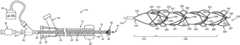
- FIG. 1is a partial sectional side view of one embodiment of a thromboembolic removal system, including a guide and occlusion catheter, a delivery and aspiration catheter, an aspiration pump, a thromboembolic receiver, and a thromboembolic separator;
- FIG. 2is a partial sectional side view of a delivery and aspiration catheter forming part of the thromboembolic removal system shown in FIG. 1 , illustrating a thromboembolic receiver element in an undeployed state;
- FIG. 3is a partial sectional side view of a delivery and aspiration catheter forming part of the thromboembolic removal system shown in FIG. 1 , illustrating the thromboembolic receiver element in a deployed state;
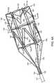
- FIG. 4Ais a perspective view depicting an alternate embodiment of a thromboembolic receiver, equipped with a plurality of engagement elements.
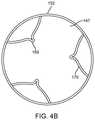
- FIG. 4Bis a cross section view taken along the plane designated 4 B- 4 B in FIG. 4A .
- FIG. 4Cis a perspective view illustrating the distal portion of the thromboembolic receiver of FIG. 4A .
- FIG. 5is a plan view of the alternate thromboembolic receiver of FIG. 4 .
- the receiveris preferably a tubular structure
- FIG. 5shows it opened and flattened into a sheet so that its features may be more easily viewed;
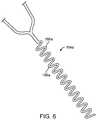
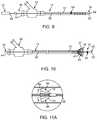
- FIG. 6is a top view illustrating one embodiment of a flex region for use in flexibly coupling the thromboembolic receiver, such as the receiver of FIG. 4A , to an elongate member or a delivery and aspiration catheter;
- FIG. 7is a perspective view of an alternate thromboembolic receiver, equipped with a plurality of engagement elements capable of being selectively deployed after the deployment of the thromboembolic receiver.
- FIG. 8Ais perspective view of a thromboembolic receiver having features for facilitating reloading of the receiver into a catheter.
- FIG. 8Bis a plan view similar to the view of FIG. 5 showing the thromboembolic receiver of FIG. 8A .
- FIG. 8Cis a perspective view of a proximal portion of the thromboembolic receiver of FIG. 8A and the distal portion of the elongate member coupled to the thromboembolic receiver, illustrating retraction of the thromboembolic receiver into a delivery and aspiration catheter.
- FIGS. 9 and 10are partial sectional side views of one embodiment of a thromboembolic disrupter or separator in use with a delivery and aspiration catheter.
- FIG. 11Ais an enlarged view of the separator element forming part of the thromboembolic separator shown in FIGS. 9 and 10 .
- FIG. 11Bis a side elevation view of an alternate embodiment of a thromboembolic separator.
- FIG. 11Cis an enlarged view of the separator element forming part of the thromboembolic separator shown in FIG. 11B .
- FIG. 11Dis a side elevation view similar to FIG. 11C showing another alternate embodiment of a thromboembolic separator.
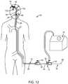
- FIG. 12is a partial sectional view of a patient illustrating the thromboembolic removal system of FIG. 1 in use within the arterial system.
- FIG. 13is a partial sectional view of a patient illustrating the distal region of the thromboembolic removal system of FIG. 1 in use within a cerebral artery.
- FIG. 14is a partial section side view illustrating advancement of a guide wire to a thromboembolism.
- FIG. 15is a partial section side view illustrating advancement of the guide and occlusion catheter, with the balloon in a deflated state.
- FIG. 16is a partial section side view illustrating inflation of the balloon occlusion member to arrest the blood flow within the artery containing the thromboembolism.
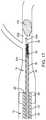
- FIG. 17is a partial section side view illustrating the step of advancing the delivery and aspiration catheter of FIGS. 1-3 to a point proximal to the thromboembolism according to a method for using the system of FIG. 1 .
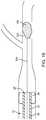
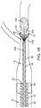
- FIG. 18is a partial section side view illustrating deployment of the thromboembolic receiver of FIGS. 1-3 .
- FIG. 19is a partial section side view illustrating advancement of the delivery and aspiration catheter of FIGS. 1-3 distally such that the thromboembolic receiver of FIGS. 1-3 engages (fully or partially) the thromboembolism.
- FIGS. 20 and 21are partial section side views illustrating movement of the thromboembolic receiver of FIGS. 1-3 into the guide and occlusion catheter so as to remove the thromboembolism.
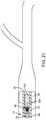
- FIG. 22is a partial section side view illustrating use of the thromboembolic separator of FIGS. 1 and 9-11C to engage the distal end of the thromboembolism.
- FIG. 23is a partial section side view illustrating use of the thromboembolic separator of FIGS. 1 and 9-11C to fragmentize and/or soften the thromboembolism and/or aid aspiration.
- FIG. 24is a partial section view illustrating independent use of the thromboembolic separator of FIGS. 1 and 9-11C to fragmentize and/or soften the thromboembolism and/or aid aspiration.
- FIGS. 25 and 26are partial section side views illustrating advancement of the thromboembolic receiver of FIGS. 4-6 distally such that it envelopes the thromboembolism.
- FIGS. 27 and 28are a partial section side views illustrating withdrawal of the thromboembolic receiver of FIGS. 4-6 and the delivery and aspiration catheter into the guide and occlusion catheter so as to remove the thromboembolism.
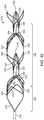
- FIG. 29is a perspective view of yet another alternate thromboembolic separator, which combines some of the features of a receiver and a separator in order to function as an improved separator equipped with a series of engagement cages, where the engagement cages are framed by uprights and apexes, and each engagement cage is defined by a pair of rib apexes that is adjoined to an adjacent pair of rib apexes.
- FIG. 30is an alternate perspective view of the thromboembolic separator of FIG. 29 .
- the thromboembolic separator of FIG. 29is rotated slightly to reveal the perspective view of FIG. 30 .
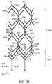
- FIG. 31is a plan (rolled out) view of the cut pattern of the thromboembolic separator of FIGS. 29 and 30 .
- the separatoris preferably a generally tubular structure
- FIG. 31illustrates it opened, flattened, and with the ribs forming the engagement cages of FIGS. 29 and 30 detached from one another, so that the features are more easily viewed.
- FIG. 32is a side view of the thromboembolic separator of FIGS. 29 and 30 disposed within a curved portion of a vessel, where the vessel is shown in cross section.
- FIG. 33is a perspective view of an alternate thromboembolic separator.
- the separator of FIG. 33has the cut pattern illustrated in FIG. 31 , but it is finished in a manner that is slightly different than the method used to finish the separator of FIGS. 29 and 30 .
- FIG. 34is a plan view of an alternate cut pattern for a thromboembolic separator. Although a resulting thromboembolic separator formed from the pattern of FIG. 34 is preferably a generally tubular structure, FIG. 34 illustrates it opened and flattened, and with the ribs forming the engagement cages detached, so that the features are more easily viewed.
- FIG. 35is a perspective view of yet another alternative embodiment of a thromboembolic separator according to the invention.
- FIG. 36is an alternate perspective view of the thromboembolic separator of FIG. 35 .
- the thromboembolic separator of FIG. 35is rotated slightly to reveal the perspective view of FIG. 36 .
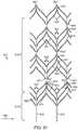
- FIG. 37is a plan view or rolled out of the cut pattern of the thromboembolic separator of FIGS. 35 and 36 .
- the separatoris preferably a generally abstract tubular structure
- FIG. 37illustrates it opened and flattened, and with the ribs forming the engagement cages of FIGS. 35 and 36 unattached, so that the features are more easily viewed.
- FIG. 1illustrates an exemplary embodiment of a thrombolic removal system 10 .
- the thromboembolic removal system 10includes a guide and occlusion catheter 12 , a delivery and aspiration catheter 14 , a thromboembolic disrupter or separator 16 , and an aspiration pump 18 .
- the thromboembolic removal system 10advantageously provides the ability to restore patency to and remove a thromboembolism from a cerebral artery within a patient while overcoming the drawbacks and limitations of the prior art.
- the guide and occlusion catheter 12includes a tubular catheter member 20 having a main lumen 22 extending between a proximal end 24 and a distal end 26 .
- the catheter member 20may be constructed from any number of compositions having suitable biocompatibility and strength characteristics, and may be dimensioned in any number of suitable sizes and lengths depending upon the entry point into the vasculature, the location of the thromboembolism, variances in patient anatomy, and any extenuating circumstances.
- the catheter member 20may be constructed from nylon with embedded stainless steel braid and dimensioned having a length ranging from 70 cm to 110 cm and a diameter ranging from 5 French (0.065 inch) to 9 French (0.117 inch).
- a balloon occlusion member 28is disposed at or near the distal end 26 .
- an inflation port 30is provided in fluid communication with the occlusion member 28 via at least one lumen (not shown) disposed within the wall of the tubular catheter member 20 .
- a seal 32is provided for passing the delivery and aspiration catheter 14 through the main lumen 22 of the guide and occlusion catheter 12 in leak-free, hemostatic fashion.
- the delivery and aspiration catheter 14includes a tubular catheter element 34 having a main lumen 36 extending between a distal end 38 and a proximal end 40 .
- the catheter member 34may be constructed from any number of compositions having suitable biocompatibility and strength characteristics, and may be dimensioned in any number of suitable sizes and lengths depending upon the entry point into the vasculature, the location of the thromboembolism, variances in patient anatomy, and any extenuating circumstances.
- the catheter member 34may be constructed from pebax with embedded stainless steel braid and dimensioned having a length ranging from 130 cm to 170 cm and a diameter ranging from 2.5 French (0.032 inch) to 5 French (0.065 inch).
- the delivery and aspiration catheter 14also includes a hub assembly 42 coupled to the proximal end 40 for the purpose of coupling the lumen 36 to the aspiration pump 18 .
- the hub assembly 42also includes a seal 44 for allowing the passage of the thromboembolic separator 16 (as well as any pushing devices to deploy a receiver element 46 , as will be discussed below) through the lumen 36 in leak-free, hemostatic fashion.
- the lumenis preferably coated with PTFE or another of the various suitable lubricious materials known in the art.
- the thromboembolic receiver element 46is capable of being restrained in a withdrawn or undeployed state within the lumen 36 ( FIG. 2 ) and selectively pushed out and/or unsheathed from the distal end 38 into a deployed state ( FIG. 3 ).
- the thromboembolic receiver 46may be constructed from any number of compositions having suitable biocompatibility and strength characteristics, and may be dimensioned in any number of suitable sizes and lengths depending upon the location of the thromboembolism, variances in patient anatomy, and the size and shape of the thromboembolism. As best viewed in FIGS.
- the thromboembolic receiver 46is formed from a plurality of strut members 47 , which upon being deployed, create a multitude of generally diamond-shaped openings 49 along the periphery of the thromboembolic receiver 46 .
- the resulting points at the distal region of the thromboembolic receiver 26are equipped with blunt tip features 51 to facilitate passage of the thromboembolic receiver 46 through the cerebral artery without snagging or becoming otherwise stuck on the arterial walls or branch vessels leading into the cerebral artery.
- a pusher element 48may be provided within the catheter element 34 for use in advancing or pushing the receiver element 46 from within the lumen 36 to assume a fully or partially deployed state.
- the pusher element 48comprises an elongate member 50 of suitable construction (e.g. wire or wire-wound) having a distal abutment 52 dimensioned to contact proximal terminal(s) 54 forming part of (or coupled to) the receiver element 46 .
- the pusher element 48may comprise any number of suitable devices for pushing the receiver element 46 for deployment, including but not limited to a catheter having a distal end dimensioned to contact the proximal terminal(s) 54 of the receiver element 46 .
- such a pusher-cathetermay have an internally disposed lumen dimensioned to receive and/or pass the thromboembolic separator 16 .
- FIG. 4Aillustrates a thromboembolic receiver 146 of an alternate embodiment.
- the thromboembolic receiver 146may be constructed from any number of compositions having suitable biocompatibility and strength characteristics, and may be dimensioned in any number of suitable sizes and lengths depending upon the location of the thromboembolism, variances in patient anatomy, and the size and shape of the thromboembolism.
- the thromboembolic receiver 146is constructed from Nitinol with “shape memory” or superelastic characteristics. In this fashion, the thromboembolic receiver 146 is capable of being retained in a constrained form or shape prior to deployment.
- the receivermay be formed by laser cutting features into a length of Nitinol tubing, and then chemically etching and shape-setting the material one or more times using methods known to those skilled in the art.
- receiver 146is mounted to an elongate member 151 preferably proportioned to extend through lumen 36 ( FIG. 1 ) of the delivery and aspiration catheter 14 .
- Strut members or “legs” 162extend between receiver 146 and elongate member 151 using bonding, shrink tubing, or other known methods.
- member 151is an elongate rod, catheter, wire or other elongate member.
- the thromboembolic receiver 146is proportioned so that it may be constrained in a compressed position within the delivery and aspiration catheter 14 (in a manner similar to that shown in FIGS. 1-3 ).
- the elongate member 151may be the delivery and aspiration catheter 14 , in which case the receiver 146 and delivery and aspiration catheter 14 are proportioned to extend through the guide and occlusion catheter 12 .
- the thromboembolic receiver 146may be automatically deployed—due to the shape memory or superelastic characteristics of Nitinol—by simply advancing the thromboembolic receiver 146 out of the element constraining it in the undeployed state (e.g. the guide and occlusion catheter 12 or the delivery and aspiration catheter 14 ). Once deployed, the thromboembolic receiver 146 may be employed to retrieve a thromboembolism.
- the dimensions of the receiver 146are preferably selected such that when it is in an expanded condition at body temperature, the exterior surface of the distal portion of the receiver contacts the surround walls of the blood vessel.
- the receivermay expand to a maximum outer diameter of approximately 2-6 mm, and more preferably 2-5 mm.
- a maximum outer diameter in the range of approximately 6-9 mmmay be suitable.
- the thromboembolic receiver 146may be formed having any variety of suitable geometries and features without departing from the scope of the present invention. According to one embodiment shown in FIGS. 4A and 5 , the thromboembolic receiver 146 is formed from a plurality of strut members, which upon being deployed, create a multitude of generally rectangular openings 149 (best viewed in FIG. 5 ) along the periphery of the thromboembolic receiver 146 .
- the strut memberscollectively define a generally cylindrical distal portion having a central lumen 147 as shown in FIG. 4B .
- the transverse strut members 152may include any number of curves or undulations, such as curves 153 a shown near the points of intersection between the transverse strut members 152 and the standards 150 , as well as the curves 153 b midway between the points of intersection as shown in FIG. 5 .
- curves or undulationshelp allow the thromboembolic receiver 146 to fold into a compressed or constrained state, which is required in order to dispose the thromboembolic receiver 146 within the delivery and aspiration catheter 14 or within the guide and occlusion catheter 12 .
- the transverse strut members 152form, in a preferred embodiment, a proximal cuff 154 located closest to the delivery and aspiration catheter 14 , a distal cuff 156 located at the distal or open end of the thromboembolic receiver 146 , and a middle cuff 158 located at some point between the proximal and distal cuffs.
- Each cuff(proximal 154 , middle 158 , and distal 156 ) is a circumferential ring designed to enhance the structural support and stability of the thromboembolic receiver 146 , as well as to aid in maintaining the thromboembolic receiver 146 in a desired shape upon deployment (for improved apposition to the vessel wall to optimize the thromboembolic retrieval).
- the structural support provided by the cuffs 154 - 158may be augmented by providing one or more stabilizing strut members 160 within one or more of the generally rectangular openings 149 .
- these stabilizing strut members 160may take the form of a “V” extending from either the proximal end or distal end of a given generally rectangular opening 149 within the thromboembolic receiver 146 .
- such “V” shaped stabilizing strut members 160are provided within the proximal and distal set of generally rectangular openings 149 within the thromboembolic receiver 146 . This advantageously adds to the structural stability of the proximal and distal regions of the thromboembolic receiver 146 .
- the stabilizing strut members 160preferably include folding regions or apexes 169 that allow them to fold at the apexes 169 (see arrows A in FIG. 5 ) when the receiver is compressed into the collapsed position. Additionally, the receiver is preferably constructed so as to permit the strut members 160 to fold in the region where they intersect with other elements forming the receiver (e.g. in the FIG. 5 embodiment, the region of intersection between strut members 160 and standards 150 ).
- relative flexibilityis provided at the junction between the thromboembolic receiver 146 and the elongate member 151 (or the distal end of the delivery and aspiration catheter 14 ). This is accomplished, by way of example only, by providing the plurality of connector strut members or “legs” 162 extending between the proximal cuff and the elongate member 151 to include (as best viewed in FIG. 5 ) a flex region 164 near the distal end of the elongate member 151 .
- the flex regions 164may be formed into any shape that will add flexibility to the strut members 162 without comprising the user's ability to transmit axial forces along the length of the strut members 162 .
- the flex regions 164 amay comprise a plurality of meandering “S” shaped struts 166 a at the proximal ends of the connector struts 162 .
- a flex region or spring region 168( FIG. 5 ) (which may comprise one of more “S” shaped curves or other shapes designed to provide flexibility while maintaining adequate column strength) may be provided at the junction between adjacent longitudinal strut members or standards 150 .
- such flex regions 164 , 168are advantageous in that they allow the thromboembolic receiver 146 to better track and follow tortuous vessels without sacrificing needed column strength.
- the thromboembolic receiver 146may also include a variety of features to augment engagement between the thromboembolic receiver 146 and the thromboembolism. This may be accomplished, by way of example only, by providing a plurality of engagement elements 170 on the thromboembolic receiver. As best viewed in FIGS. 4A, 4B and 5 , the engagement elements 170 may, according to one embodiment, take the form of a “V” shaped structure coupled at or near the distal end of the thromboembolic receiver 146 and extending between adjacent standards 150 . The engagement elements preferably angle into the lumen 147 of the thromboembolic receiver (see FIGS.
- engagement elements 170may be employed without departing from the scope of the present invention. In one embodiment, three (3) separate engagement elements 170 may be employed, each being disposed one hundred and twenty (120) degrees from one another along the periphery of the thromboembolic receiver 146 . In a preferred embodiment, the engagement elements 170 take the form of a plurality of the stabilizing strut members 160 as shown in FIGS. 4A and 5 .
- the engagement elements 170may be deployed automatically when the thromboembolic receiver 146 is deployed (as shown in FIG. 4-5 ).
- the engagement elements 170 amay also be selectively deployed at any point following the deployment of the thromboembolic receiver 146 a .
- the selective deployment of the engagement elements 170 ais accomplished by passing one or more elongate elements 172 through the thromboembolic receiver 146 a such that the engagement elements 170 a are prevented from extending medially into the lumen of the thromboembolic receiver 146 .
- a userWhen deployment is desired, a user need only pull the elongate elements 172 in a proximal direction (towards the user) until the engagement elements 170 a are set free from the constraint of the elongate elements 172 . When this occurs, the “shape memory” or superelastic nature of the engagement elements 170 a will cause them to assume their natural state, extending medially into the lumen of the thromboembolic receiver 146 a . In this fashion, the engagement elements 170 a will engage the thromboembolism and thus aid or enhance the ability of the thromboembolic receiver 146 a to remove a thromboembolism.
- the thromboembolic receivermay be provided with features that allow a surgeon to retract the receiver back into the delivery and aspiration catheter after the receiver has been partially or fully deployed into a blood vessel. This might be necessary if, perhaps, the surgeon receives angiographic or tactile feedback indicating that a separator would be a preferred tool for removal of a particular embolism, or that a receiver of a different size would be more suitable for a particular procedure.
- FIG. 8Aillustrates one example of an embodiment of a thromboembolic receiver 146 b that is similar to the receiver 146 of FIG. 4 , but that includes the features that facilitate reloading of the receiver into the delivery and aspiration catheter 14 .
- receiver 146 b of the FIG. 8A embodimentincludes a single, distal, cuff 152 b and a plurality of longitudinal strut members 150 b extending proximally from the cuff 152 b.
- Structural support members 160 bare arranged in a distal row 171 a adjacent to the cuff 152 b , and a more proximal row 171 b as shown in FIG. 8B .
- a plurality of the structural support members 160 b in the distal roware inwardly biased into the central lumen 147 b of the receiver 146 b so as to function as engagement members 170 b for engaging a thromboembolism.
- strut members 162 bextend distally from the apexes of those of the structural support members 160 b in the distal row 171 a that do not function as engagement members. These strut members 162 b are coupled at an intermediate point to the apexes of longitudinally aligned support members 160 b in the proximal row.
- strut members 162 cform the proximal extensions of the longitudinal strut members 150 b and include eyelets 163 at their proximal ends.
- strut members 162 dextend from the apexes of those of the structure support members 160 b in the proximal row that are longitudinally aligned with the engagement members 170 b . Flexibility may be added to the receiver 146 b may constructing some or all of the strut members to include flex regions of the type described in connection with earlier embodiments (see, e.g. flex regions 168 of FIG. 5 ).
- the receiver 146 bincludes a pusher or elongate member 151 b that includes a lumen 165 at its distal end.
- the proximal ends of strut members 162 b and 162 dare positioned within the lumen 165 as shown and are allowed to slide freely within the lumen 165 .
- the proximal ends of strut members 162 care bonded to the exterior surface of the elongate member 151 b using heat shrink tubing 167 or other suitable material.
- the eyelets 163facilitate bonding by allowing the bonding material to flow into the openings of the eyelets, thereby exposing a larger portion of each strut member 162 c to the bonding material.
- the strut members 162 b and 162 dmay be somewhat longer than the strut members 162 c at the proximal end of the receiver, to allow them to be easily identified for insertion into the lumen 165 during assembly.
- the elongate member 151 bis withdrawn in a proximal direction relative to the catheter as shown in FIG. 8C .
- the receiverbegins to fold at the apexes of the structural support members 162 b and 162 d in a proximal direction. Folding is more easily accomplished than with the receiver 146 of FIG. 4 due to the fact that certain of the structural support members 160 b are interconnected at their apexes by strut members 162 b .
- the folding of one member 160 b in the proximal row 171 bwill facilitate the folding of a corresponding member 160 b in the distal row 171 a .
- the strut members 162 b and 162 dare allowed to slide freely within the lumen 165 of the elongate member 151 b so that they will not resist folding of the members 160 b during withdrawal of the receiver 146 b into the catheter 14 .
- FIG. 9A first embodiment of a thromboembolic separator is shown in FIG. 9 .
- the thromboembolic separator 16 of the first embodimentincludes an elongated element 56 having a proximal end 58 and a distal end 60 .
- the elongated element 56may be constructed from any number of compositions having suitable biocompatibility and strength characteristics, and may be dimensioned in any number of suitable sizes and lengths depending upon the entry point in vasculature, the location of the thromboembolism, variances in patient anatomy, and any extenuating circumstances.
- the elongated element 56may be constructed from stainless steel and/or Nitinol and dimensioned having a length ranging from 150 cm to 200 cm and a diameter ranging from 0.010 inch to 0.021 inch.
- a lubricious surfacee.g., a PTFE coating, hydrophilic coating, or other suitable coatings may be applied to all or a portion of the elongate element 56 to facilitate movement of the element within the lumen of the delivery/aspiration catheter 14 and/or within the vasculature.
- the elongate element 56may take the form of a guide wire of the type used in various vascular applications.
- the elongate elementmay thus optionally include a coiled distal section 57 ( FIG. 11B ) having sufficient flexibility to prevent trauma to vascular tissues during advancement of the guidewire.
- coiled distal section 57may have a length in the range of approximately 27-33 cm.
- the coilis preferably positioned around an inner mandrel or core (not shown) of a type commonly found in coiled guidewires.
- the “working end” of the separator 16includes a generally blunt tip element 62 attached or forming part of the distal end 60 of the elongated element 56 , and a separator element 64 attached or forming part of the elongated element 56 .
- the tip element 62is preferably dimensioned to pass through or against a thromboembolism so as to soften or fragment the thromboembolism for removal.
- the blunt nature of the tip element 62is advantageously atraumatic such that it will not cause damage to the interior of the vasculature during use.
- the separator 16also assists in removing any clogs or flow restrictions that may develop within the lumen 36 due to the passage of thromboembolic material therethrough during aspiration.
- the separator element 64may take the form of a basket that is generally conical in shape, with an opening 66 facing proximally along the elongated element 56 .
- the separator basket 64is dimensioned to assist in the thromboembolic fragmentation process, as well as to receive such thromboembolic fragments to aid in their removal.
- the separator basket 64is provided having a web 68 and one or more support members 70 .
- the support members 70are dimensioned to bias the web 68 into the generally open position shown and, if desired, to allow the web 68 to assume a generally closed position (not shown, but generally flush against the elongated element 56 ) as the separator 16 is passed through delivery and aspiration catheter-style pusher as described above, and/or the thromboembolism itself.
- separator 16 aais shown in FIGS. 11B and 11C , in which like reference numerals are used to identify features similar to those shown in FIGS. 9, 10 and 11A .
- Separator 16 adiffers from separator 16 of FIGS. 9, 10 and 11A primarily in the features of the separator element 64 a .
- separator element 64 ais a conical member formed of a polymeric material such as polyurethane or Pebax® polyether block amides, to name a few.
- the separator element 64 ais preferably a solid member, with a surface 65 facing in the proximal direction, and with the taper of the element oriented in a distal direction.
- Surface 65may be contoured in a variety of ways. For example, surface 65 may be slightly concave as shown in FIG. 11B , substantially planar as shown in FIG. 11C , or slightly convex as shown in FIG. 11D .
- the separator element 64 ais positioned on the coiled distal section 57 of the elongate element 56 .
- the pitch of a portion of the coiled section 57may be decreased in certain regions of the coiled distal section 57 . Opening the spacing in the coil in this manner can facilitate adhesion between the polymeric material of the separator element and the coil material during the molding process.
- the spacing between the separator element 64 a and the distal end 60 of the elongate element 56is preferably long enough to allow the distal-most portion of the elongate element sufficient flexibility to move atraumatically through the vasculature, but short enough to prevent folding of the distal-most portion during advancement of the elongate element 56 .
- the distal end of separator element 64 amay be positioned approximately 3-9 mm from the distal end 60 . It should be noted that the mandrel or core (not shown) within the coiled section 57 of the elongate element 56 might have a tapered diameter selected to enhance the flexibility of the coiled section.
- a handle member 72( FIG. 9 ) is provided at the proximal end 58 of the separator to provide a purchase point for a user to advance and/or manipulate the atraumatic tip element 62 and separator 64 / 64 a .
- the handle member 72may be coupled to the elongated element 56 in any suitable fashion, including, but not limited to providing a generally rigid extension (not shown) disposed within the elongated element 56 for the purpose of coupling the two components together. This coupling may be augmented or strengthened through the use of any number of adhesives or fusing techniques.
- the separator 16may be provided in a variety of different permutations without departing from the scope of the present invention.
- the separator basket 64 of FIG. 11Amay be selectively deployed, such as by equipping the separator basket 64 with a mechanism to selectively bias or open the support members 70 from an initial position lying generally flush against the elongated element 56 to a generally radially expanded position (shown with arrows in FIG. 11A ).
- the guide and occlusion catheter 12 , the delivery and aspiration catheter 14 , the thromboembolic separator 16 and/or the thromboembolic receiver 46may be provided with any number of features to facilitate the visualization of these elements during introduction and usage, including but not limited to having the distal regions equipped with radiopaque markers for improved radiographic imaging.
- the various components described hereinmay be provided as part of the system 10 for removing thromboembolic material.
- the thromboembolic removal system 10may include a guide and occlusion catheter 12 , a delivery and aspiration catheter 14 , a thromboembolic separator 16 / 16 a , a thromboembolic receiver (e.g. receiver 46 or 146 ), and an aspiration pump 18 , as well as guidewires and/or other tools appropriate for the procedure.
- multiple receivers 46 / 146may be provided, allowing the surgeon to sequentially retrieve several thromboembolisms during the course of a procedure.
- each separate receivermay be provided with a separate delivery and aspiration catheter.
- the system 10may additionally be provided with instructions for use setting forth any of the various methods of use described herein, or equivalents thereof.
- FIGS. 12-28Methods of using the thromboembolic removal system 10 will now be described with reference to FIGS. 12-28 .
- the thromboembolic removal system 10is introduced into the patient's vasculature, such as via the Seldinger technique.
- FIG. 14illustrates the first step of this process, which involves advancing a guide wire 104 to a point proximal to a thromboembolism 100 .
- the guide wire 104may comprise any number of commercially available guide wires, the operation of which is well known in the art.
- the elongate member 56 ( FIG. 11B ) of the separator 16functions as the guidewire 104 .
- FIG. 15illustrates a second step, which involves advancing the guide and occlusion catheter 12 over the guide wire 104 to a point proximal to the thromboembolism.
- the next stepshown in FIG. 16 , preferably involves inflating the balloon occlusion member 28 so as to arrest the blood flow within the cerebral artery 102 containing the thromboembolism 100 .
- the delivery and aspiration catheter 14is then advanced through the guide and occlusion catheter 12 such that the distal end 38 of the delivery and aspiration catheter 14 is positioned at a point proximal to the thromboembolism 100 . This may be facilitated by advancing the delivery and aspiration catheter 14 over the guide wire (not shown but well known in the art) extending through the guide and occlusion catheter 12 .
- the thromboembolic receiver 46is deployed from the distal end 38 of the delivery and aspiration catheter 14 .
- the balloon occlusion 28may be inflated at this point (as opposed to inflating it before the delivery and aspiration catheter 14 is advanced, as shown in FIG. 16 ).
- the delivery and aspiration catheter 14is then advanced distally—as shown in FIG. 19 —such that the thromboembolic receiver 46 engages and/or envelops (partially or fully) the thromboembolism 100 .
- the delivery and aspiration catheter 14may be withdrawn into the guide and occlusion catheter 12 to remove the thromboembolism 12 from the patient.
- the aspiration pump 18may be activated to establish negative pressure within the delivery and aspiration catheter 14 . In this fashion, negative pressure will be created within the cerebral artery 102 and exerted upon the thromboembolism 100 .
- the separator 16(or the separator 16 a of FIGS. 11B-D ) may be employed during this process (e.g. advancing and retracting it within the lumen 36 of the delivery and aspiration catheter 14 ) to remove any clogs or flow restrictions due to the passage of thromboembolic material through the lumen 36 .
- the negative pressurewill serve to draw the thromboembolism 10 into (partially or fully) the thromboembolic receiver 46 .
- the delivery and aspiration catheter 14may then be withdrawn into the guide and occlusion catheter 12 to remove the thromboembolism 100 from the patient.
- the thromboembolic separator 16 / 16 amay be advanced into contact with a portion of the thromboembolism, or completely through the thromboembolism 100 as shown in FIG. 22 , and employed to bias or engage the distal end of the thromboembolism 100 .
- the separator 16 / 16 amay also be selectively advanced and retracted through the thromboembolism 100 (or that remaining outside the receiver 46 ). This will serve to break up or otherwise soften the thromboembolism 100 . Advancing and retracting the separator 16 / 16 a also serves to remove any clogs or flow restrictions within the lumen of the delivery and aspiration catheter 14 during the aspiration due to the passage of thromboembolic material through the lumen 36 of the delivery and aspiration catheter 14 .
- the aspiration pump 18will draw or bias the thromboembolic fragments 106 or the softened thromboembolism 100 into the thromboembolic receiver 46 and/or into catheter 14 .
- the delivery and aspiration catheter 14may then be withdrawn such that the thromboembolic receiver 46 is drawn into the guide and occlusion catheter 12 to remove the thromboembolism 100 from the patient.
- Selective advancement of the separator element 64 through the thromboembolism and retraction of the separator element into the delivery and aspiration catheter 14can additionally be used to carry small “bites” of the thromboembolic material, displacing some material and thus forming a channel in the material as it moves distally. Once the separator element is positioned further into, or distally of, the thromboembolism, some of the displaced material may flow back into this channel. Subsequent retraction of the separator element 64 through the material (e.g. through the re-filled channel) will then draw some of the material into the catheter 14 .
- the separator element 64 and the catheter 14are preferably provided with fairly tight tolerances between the diameter of the catheter lumen 36 and the greatest diameter of the separator element 64 .
- the outer diameter of separator element 64 and the diameter of lumen 36may differ by approximately 0.003-0.008 inches.
- an initial determinationis made concerning whether use of receiver 146 or separator 16 a will first be employed. This determination may be made at random, although in a preferred method the surgeon selects the appropriate tool based on a determination of the likely nature of the thromboembolic material that is to be removed. In particular, the surgeon will assess the patient to determine whether the material is likely to be hard or soft/gelatinous. This assessment might include an evaluation of one or more factors such as the response of the tip of the guidewire or separator when it is brought in contact with thromboembolism, the location of the thromboembolic material, patient symptoms, and/or the manner in which the stroke caused by the thromboembolism is manifesting itself.
- the guide and occlusion catheter 12is introduced into the patient's vasculature, and the occlusion balloon 28 is inflated to arrest the flow of blood within the vessel (see, for example, FIGS. 14-16 ).
- the delivery and aspiration catheter 14is passed through the guide and occlusion catheter 12 and positioned with its distal end at a location proximal to the thromboembolism 100 . If the surgeon elects to use the separator 16 a prior to using the receiver 146 , or if the assessment results in a determination that the thromboembolic material is likely to be somewhat soft or gelatinous, the aspiration pump 18 is activated to establish negative pressure within the delivery and aspiration catheter 14 , and thus to exert negative pressure exerted upon the thromboembolism 100 to draw embolic material into the catheter 14 .
- the separator 16 ais deployed from the distal end of the delivery and aspiration catheter 14 and moved into contact with the thromboembolic material 100 as shown in FIG. 24 .
- the separatormay be advanced and retracted multiple times if desired. When advanced and retracted as shown, the separator can facilitate aspiration of the thromboembolic material into the catheter 14 in one of a variety of ways. First, movement of the separator into contact with the thromboembolism can loosen, separate, or soften pieces of thromboembolic material, such that pieces of the thromboembolism can be aspirated into the catheter.
- advancing and retracting the separator 16 aserves to remove any clogs or flow restrictions within the lumen 36 of the delivery and aspiration catheter 14 that might be caused by the passage of thromboembolic material through the lumen 36 . Additionally, during retraction of the disrupter 16 a , its proximal surface 35 may push or plunge loosened material towards and/or into the distal end of the catheter 14 for subsequent aspiration out of the body.
- the disrupter 16 ais preferably withdrawn from the catheter 14 and a thromboembolic receiver 146 is passed through the delivery and aspiration catheter 14 and deployed within the blood vessel. If the system is provided with multiple sizes of receivers, the surgeon will select a receiver having an appropriate size for the blood vessel being treated.
- the receiver 146expands into contact with the surrounding walls of the vessel.
- the walls of the receiver 146slip around the body 200 to engage and/or envelop (partially or fully) the thromboembolism.
- the engaging elements 170engage the thromboembolism 200 , thereby retaining it within the receiver.
- the delivery and aspiration catheter 14may be advanced slightly in a distal direction as indicated by arrows in FIG. 27 , so as to “cinch” the strut members 162 towards one another, thus causing the receiver 146 to collapse slightly in a radially inward direction.
- the aspiration pump 18may be activated to facilitate retention of the thromboembolism 200 within the receiver.
- the delivery and aspiration catheter 14 , the receiver 146 and the thromboembolism 100are withdrawn into the guide and occlusion catheter 12 and are withdrawn from the body. If additional thromboembolic material should remain in the blood vessel, a new delivery and aspiration catheter 14 may be passed into the blood vessel, and a new receiver may be deployed through the catheter 14 for retrieving the additional body of thromboembolic material.
- the surgeonmay elect to initially deploy the receiver rather than the separator, such as if the initial assessment results in a determination that the thromboembolic material is likely to be hard.
- the methodis then carried out utilizing the receiver 146 as described in the preceding paragraph. If it is later determined that residual thromboembolic material (e.g. soft or gelatinous material) is present in the vessel, the receiver 146 is preferably removed from the body, and the separator 16 a is passed through the delivery and aspiration catheter 14 .
- the aspiration pump 18is activated and the separator 16 a is manipulated to facilitate aspiration of the soft material in the manner described above.
- FIGS. 29 and 30an alternate embodiment of a thromboembolic separator 310 is shown.
- the thromboembolic separator of FIGS. 29 and 30combines many of the features of the receivers and separators discussed above, in order to perform as an improved separator.
- FIG. 29is a perspective view of thromboembolic separator 310 .
- FIG. 30is also a perspective view of thromboembolic separator 310 , but is rotated slightly from the view of FIG. 29 in order to reveal characteristics that are not visible in FIG. 29 .
- FIG. 29can be consulted for an illustration of features that are slightly obstructed in the view of FIG. 30 .
- Thromboembolic separator 310may be constructed from any number of materials or compositions having suitable biocompatibility and strength characteristics, and may be dimensioned in any number of suitable sizes and lengths depending upon the location of the thromboembolism, variances in patient anatomy, and the size and shape of the thromboembolism.
- the outer diameter of separator 310 in its deployed (radially expanded) configurationmay range between 4.6 mm and 5.4 mm to be used in vessels ranging from 3.0 mm and larger; however other device diameters may be suitable according to the invention.
- the length of separator 310 when deployedmay vary between 12 mm and 20 mm, but preferably is longer than the length of the thromboembolism, and in this instance is approximately 17 mm.
- Separator 310is constructed from a nickel-titanium alloy (Nitinol®) with “shape memory” or superelastic characteristics. Accordingly, the thromboembolic separator 310 is capable of being retained in a constrained form or shape prior to deployment.
- the separatormay be formed by laser cutting features into a length of Nitinol tubing, then chemically etching and shape-setting the material, and then attaching cut features to one another to construct a finished device. For example, a tube of 3.5 mm outer diameter and 0.0055 inch wall thickness may be cut in a predetermined pattern. Examples of suitable patterns are illustrated as flat patterns in FIG. 31 , FIG. 34 and FIG. 37 (as though the tube were cut along a longitudinal axis and laid flat).
- Strut widths that define the elements of separator 310may vary between 0.0011 inch and 0.00165 inch. Struts may have a broadened region and one or more tapered regions. After the features are cut into the length of tubing, additional steps (which are described in greater detail below) are performed upon the features of the cut tube in order to manufacture the finished separator 310 .
- thromboembolic separatorsare defined by strut members cut into the tubing, some of which undergo additional processing in the manufacture of the finished device.
- a strut member as used hereinis a generic term for a band-like, wire-like, or other elongate element cut out of the tubing in the early steps of manufacture of a separator according to the invention. Because a separator according to the invention typically has numerous strut members having varied configurations, other terms are used in the following description to distinguish among strut members and in order to avoid confusion.
- a particular strut memberwill be longitudinal or transverse, curved, undulating, straight deflected inwardly to occupy a lumen of the tubular separator, or the like.
- the length and width of a strut membermay differ from that of another strut member and may perform a different function in the device.
- An individual strut membermay have either a uniform or a varied width along its length.
- Some strut membersare configured to define “uprights” or “standards”.
- the terms upright or standardare used interchangeably to describe a strut member that extends generally longitudinally (in a direction parallel to a central axis of the tube) along the length of the device.
- An upright or standardwill typically confer axial or columnar strength upon the device.
- uprightsare typically more or less parallel to one another throughout the length of the device.
- a first set of uprights at the base of the devicemay be referred to as “legs”.
- An upright or standardmay be the same width as or wider than other strut members that define the device's structure.
- An embodiment according to the inventionmay have any number of uprights, but those described in detail herein typically have between two and four uprights or standards.
- While uprightsare more or less parallel to one another, some strut members extend from the uprights or standards at an angle to the upright.
- the angle at which a particular strut member is oriented to a particular uprightmay vary widely, and the term angle should be understood to mean any angle within the full spectrum greater than 0 degrees and less than 180 degrees, but will most often be between 15 degrees and 75 degrees.
- the strut members that extend from an upright at an angle to the uprightmeet other strut members attached to an opposite upright and also extending at an angle to the opposite upright.
- the term “apex”is used herein to refer to two strut members that meet at their distal end to form a peak or “apex”.
- An apexmay be pointed or rounded, may be attached to an upright, to another apex (so that in effect four struts meet at a common apex), or may be free.
- An apexmay be slightly “cupped” in a deployed device.
- An apexmay be disposed along a “wall” of a separator or, alternatively, may be disposed or deflected to lie within a central “lumen” of the separator. Further, an apex may include an additional extension therefrom.
- An apex that is left freeis referred to as an apex, but with an added indication of the relative location of the apex.
- a proximal apexis located at the proximal end of the device
- a distal apexis located at the distal end of the device.
- a body apexis located along the body of the device, and may be numbered consecutively as first body apex, second body apex, and so on, from the proximal end of the device to the distal end of the device.
- An apex that is attached at its distal end to an uprightmay be referred to as a “fork” at its point of attachment to the upright.
- an apex that is formed where the distal end of an upright dividesmay be described as “Y-like”.
- An apex that may be coupled to another apex in the central lumen of the deviceis referred to as a “peak”, whether the apex is coupled or remains unattached in the finished device.
- An attached pair of peaks, typically disposed within the central lumen of the device,is referred to as a “cage”.
- ribis typically a strut member that extends from an upright at an angle to the upright until it meets another rib coming from an opposing upright to define a “peak”.
- a peakmay also have a “rib extension” extending therefrom.
- a peak and its respective rib extensionmay define a wish-bone like configuration.
- a peakmay be attached to another peak or may remain unattached in a finished device. Where a peak is coupled to a second peak, the paired rib peaks are referred to as a “cage”. Ribs, peaks, and rib extensions forming a cage are typically biased into the central lumen of the device when they are coupled with a second pair of ribs, peaks and extensions.
- An “arm”is also a strut that extends from an upright at an angle to the upright. Arms extend generally in a “Y-like configuration” in a distal direction from an upright. Distal to the point where arms divide in a Y-like fashion, two arms meet again at a subsequent upright.
- the term “fork”may be used to describe the point at which two arms meet at a distal upright to define an apex. While all of the foregoing terms refer to struts and apexes, it is hoped that the additional terms enable a clearer distinction among struts and apexes and a clearer description of a device according to the invention.
- separator 310After material is removed from a Nitinol tube according to a predetermined pattern, and following the final steps to construct separator 310 , the structure of separator 310 is a generally skeletal device bearing “internal” elements.
- the body abstracted from the tubehas large voids in its “walls” and loosely defines a central axis 330 therethrough.
- the abstract tubehas an outer circumference disposed about the central axis.
- the series of internal elementsis disposed about central axis 330 . These internal elements are referred to as engagement cages 350 , 351 , 352 and 353 .
- Separator 310FIGS.
- engagement cage 29 and 30includes four such engagement cages 350 , 351 , 352 and 353 , but may according to the invention include a greater or lesser number.
- Engagement cages 350 , 351 , 352 and 353along with other elements of the device, engage embolic material in a vessel of a subject during use of separator 310 , in order that the embolic material may be removed and vessel patency restored.
- Engagement cages 350 , 351 , 352 and 353are framed first by uprights (or standards) 320 , 321 , 322 and 326 respectively.
- Engagement cage 350is also framed by proximal apexes 313 , and by two pairs of arms 323 .
- Proximal apexes 313may cup slightly in the expanded device.
- Each pair of arms 323meets to form forks 330 at subsequent uprights 321 .
- Engagement cage 351is also framed by two pairs of arms 325 .
- Each pair of arms 325meets to form forks 332 at subsequent uprights 322 .
- engagement cage 352is also framed by two pairs of arms 327 , which meet to define forks 334 at subsequent uprights 326 .
- engagement cage 353is framed by distal apexes 357 . Similar to proximal apexes 313 , distal apexes 357 may cup slightly in an expanded device.
- separator 310is shown mounted to pusher 315 , which is proportioned to extend through the lumen of a delivery and aspiration catheter such as the PX400 catheter or other suitable catheters available from Penumbra, Inc. in Alameda, Calif. Other straight lumen catheters having an inner diameter of between 0.025-0.032 inch may be suitable.
- a suitable pusher cathetermay be constructed from Pebax HS tubing or comparable material, available from Zeus Medical of Orangeburg, S.C., though other materials and alternative dimensions may be suitable according to the invention.
- a separator according to the inventionmay in the alternative be mounted to a delivery wire, depending upon the dimensions and requirements of the delivery catheter used to deliver the separator to the treatment site.
- a delivery wiremay be of 0.014 inch distal diameter and 0.020 inch proximal diameter stainless steel, Nitinol or other metal, or other suitable dimensions and materials. If mounted upon a delivery wire, separator 310 may be mounted approximately 5 cm from the distal end of the wire, but other configurations are possible. Separator 310 may advantageously be mounted eccentrically to the pusher or delivery wire. Thromboembolic separator 310 is mounted to the distal end of pusher 315 via legs 318 .
- FIG. 31illustrates flat (rolled out) pattern 311 . Beginning at its proximal end 312 , legs 318 extend distally to form a first set of uprights 320 . Proximal apexes 313 are attached between adjacent uprights 320 . Base end 314 of separator 310 is thereby defined by legs 318 , uprights 320 , and proximal apexes 313 .
- each upright 320divides in a Y-like fashion to form a first set of arms 323 .
- Each arm 323extends at an angle to uprights 320 , or generally diagonally to meet an adjacent arm 323 at fork 330 as each arm 323 joins a subsequent set of uprights 321 extending therefrom. This pattern, which can be most easily seen in FIG. 31 , repeats until the distal end 359 of separator 310 .
- the body 316 of separator 310is thus defined primarily by successive sets of uprights 320 , 321 , 322 and 326 , successive sets of arms 323 , 325 and 327 , and forks 330 , 332 , and 334 , where the number of the sets can vary according to the invention.
- Uprights 320 , 321 , 322 and 326 , arms 323 , 325 and 327 , and forks 330 , 332 and 334skeletally frame a series of engagement cages, which will be described in detail below.
- Each set of uprightsis oriented around the circumference of separator 31 at roughly 90° to its adjacent set of uprights, as most easily seen in FIG. 30 .
- the distal end 359 of separator 320is defined by distal apexes 357 , which in the deployed separator 310 cup slightly and are oriented at approximately 90° about the central axis 330 , or around the device's circumference, to proximal apexes 313 .
- Distal apexes 357roughly frame distal most engagement cage 353 . This characteristic is most easily seen in FIG. 30 , though other features of separator 310 are obscured when the device is viewed from the perspective illustrated in FIG. 30 .
- each rib 335extends at angle to uprights 320 at its point of attachment thereto, or somewhat diagonally, to meet an adjacent rib 335 extending from the opposite direction. In this fashion, each rib 335 meets adjacent rib 335 to define a rib peak 317 to form an apex.
- rib extension 340also extending from each rib peak 317 is rib extension 340 . As best viewed in FIG.
- ribs 335 , rib peak 317 and rib extensions 340together define a wish-bone like configuration. This pattern repeats at each subsequent set of uprights 321 , 322 and 326 , defining subsequent sets of ribs 336 , 337 and 338 (and apices), and corresponding rib extensions 341 , 342 , and 343 .
- each rib extension 340 , 341 and 343is biased into central lumen 330 until it meets the respective rib extension 340 , 341 , or 343 approaching from the opposite side of separator 310 .
- Each rib extension 340 , 341 , 342 , and 343thereby biases each rib 335 , 336 , 337 , and 338 somewhat into central lumen 330 .
- Each rib extension 340 , 341 , 342 , and 343is then mated with its opposing rib extension 340 , 341 , 342 or 343 , and attached thereto via a rib extension joiner 345 , 346 , 348 or 349 , though other suitable means of attachment are within the scope of the invention.
- Ribs 335 , 336 , 337 and 338 , together with rib extensions 340 , 341 , 342 and 343thereby form engagement cages 350 , 351 , 352 and 353 , disposed within central lumen 330 .
- FIG. 32illustrates an alternate embodiment, in which only the proximal most and distal most rib extensions are attached within the central lumen. The intermediate rib extensions remain unattached, leaving opposing rib peaks generally flush with the “walls” of the device.
- the separator illustrated in FIG. 32will be discussed in greater detail below.
- separator 310Prior to delivery and deployment of separator 310 , separator 310 will be collapsed, crimped down or otherwise reduced to its delivery configuration and restrained therein by a sheath (not shown). In preparation for treating a subject, the device within its sheath will be loaded in a delivery catheter. During a procedure performed under fluoroscopic visualization, the delivery catheter is tracked to the site of the occlusion. The distal end of the catheter is tracked through the occlusion until the distal tip thereof extends beyond the occlusion. In a slight variation of the methods described above in relation to alternate embodiments, separator 310 is preferably positioned inside a thrombus prior to deployment, and advantageously will be of a length that is greater than the length of the thrombus.
- the thromboembolic separator 310is deployed from the distal end of a delivery and aspiration catheter.
- the sheath(not pictured) is then withdrawn to allow partial or complete expansion of the separator within the vessel.
- the separator 310engages a thromboembolism in a vessel.
- the sheathcan then be advanced over thromboembolic separator 310 , which readily collapses back into the sheath. A large portion or all of the thromboembolism is thereby removed from the vessel and into the catheter.
- Additional therapeuticssuch as pharmacologic agents, may be administered before and/or during deployment if desired by the physician.
- additional mechanical means for removal of thromboembolic materialmay be deployed while the separator is in place within the lumen. Further, expansion of the separator may be increased incrementally during use. And, contrast die may be injected at any point during deployment of the separator to determine the extent of restoration of blood flow.
- an aspiration pumpmay be activated to establish negative pressure within the delivery and aspiration catheter. In this fashion, negative pressure will be created within the cerebral artery and exerted upon the thromboembolism.
- the delivery sheathmay be advanced over at least a portion of the separator and into contact with a portion of the thromboembolism, at least at the proximal end of the separator. This will serve to break up, soften, and/or clear thromboembolic material that is blocking aspiration.
- Advancing and retracting the sheathrepeatedly also serves to remove any clogs or flow restrictions within the lumen of the delivery and aspiration catheter during the aspiration due to the passage of thromboembolic material through the lumen of the delivery and aspiration catheter.
- the aspiration pumpwill draw or bias the thromboembolic fragments or the softened thromboembolism into the aspiration catheter.
- the thromboembolic separator and delivery and aspiration cathetermay then be withdrawn such that the separator and aspiration catheter remove the thromboembolism from the patient.
- separator 310is preferably positioned within a thromboembolism prior to deployment.
- the thromboembolismis located within a curved vessel, and separator 310 will be deployed within a curved vessel.
- FIG. 32Clear advantages of separator 310 are illustrated in FIG. 32 , in which separator 310 is shown deployed in a curved vessel model 600 .
- separator 310When deployed within a curved tubular vessel, separator 310 resists kinking and collapsing. Further, separator 310 may be partially or fully withdrawn into a delivery sheath (not pictured) without kinking or collapsing, repositioned and redeployed. Some portions of separator 310 may expand into contact with the surrounding walls of the vessel.
- proximal apexes 313may expand into contact with the vessel wall, depending upon vessel size and morphology.
- distal apexes 357expand and may or may not contact with the vessel wall.
- Some, all, or portions of some or all of arms 323 , 325 and 327 , forks 330 , 332 and 334 , and uprights 320 , 321 , 322 and 326may also contact the vessel wall.
- separator 310generally conforms to the curvature or bend 605 of the vessel.
- Engagement cages 350 , 351 , 352 and 353may remain disposed more or less within the central lumen 330 , depending upon the degree of curvature of the vessel, vessel morphology, placement of the length of separator 310 with respect to the curvature 605 , and other factors. For example, as illustrated in FIG. 32 , portions of some engagement cages 350 , 351 , 352 and 353 may be disposed in close proximity to the vessel wall. In any event, the function of the engagement cages 350 , 351 , 352 and 353 is to engage embolic material in order to remove it from the vessel. When in actual use by the physician, the separator may be completely resheathed and removed from the vessel when desired.
- separator 310Advancement of the sheath and/or retraction of separator 310 will cause separator 310 to return to its collapsed configuration within the sheath. Embolic material will remain engaged to engagement cages 350 , 351 , 352 and 353 , and will consequently also be removed from the vessel, thereby helping to restore blood flow to the vessel. Additional treatment, whether pharmacologic or mechanical, may continue or commence according to the treating practitioners' determination.
- FIG. 33illustrates an embodiment according to the invention that is similar to that described in FIGS. 29-32 , with a few important distinctions.
- a significant distinction of separator 370 from separator 310is that separator 370 includes only two engagement cages 380 and 383 .
- the cut pattern for manufacture of separator 370 of FIG. 32is the same pattern as that illustrated in FIG. 31 .
- the process of manufacturing separator 370is the same as that used to manufacture separator 310 except for a few finishing steps. More specifically, in constructing the finished device from pattern 311 , only the proximal-most set of rib extensions 340 and the distal-most set of rib extensions 343 are biased into central lumen 385 and attached to one another to form engagement cages 380 and 383 .
- Ribs 336 and 337remain unattached to adjacent ribs and are part of the outer diameter of deployed device 370 . And because each set is oriented at roughly 90° to each subsequent set, unattached ribs 335 have generally the same orientation as distal apexes 377 , and unattached ribs 337 lie generally oriented with proximal apexes 373 .
- the methods of manufacture and methods of use of separator 370are otherwise generally the same as those methods described above in relation to FIGS. 29-32 .
- An alternate thromboembolic separator according to the inventionmay be constructed using a cut pattern as illustrated in FIG. 34 .
- proximal end 412includes legs 418 .
- a thromboembolic separator manufactured from pattern 410will be mounted at its proximal end 412 , to a pusher (not pictured) via legs 418 .
- Legs 418extend distally from the proximal end 412 to form a first set of uprights 420 .
- a row of proximal apexes 413is attached to uprights 420 .
- proximal apexes 413will surround a central lumen, and further define the base 414 of a separator constructed from pattern 410 .
- each upright 420divides in a Y-like fashion and extends substantially diagonally to form a first set of arms 423 .
- Each arm 423extends diagonally to join an adjacent arm 423 at a fork 440 .
- a second set of uprights 421extends. This pattern repeats until the distal end of cut pattern 410 .
- the body 416 of pattern 410is thus defined primarily by successive sets of uprights 420 , 421 , 422 , and successive sets of arms 423 , 425 , 427 , where the number of both sets can vary according to the invention.
- Uprights 420 , 421 , 422 , and arms 423 , 425 , 427will “surround”, or be disposed about, a central axis of a finished device.
- the distal end of pattern 420is defined by distal apexes 457 , which will also surround a central axis of a finished device.
- a rib 435Just distal to proximal apexes 413 and similarly extending from each upright 420 is a rib 435 .
- Each rib 435extends at an angle to an upright, or somewhat diagonally to meet an adjacent rib 435 extending from the opposite direction. In this fashion, each rib 435 meets adjacent rib 435 to define a rib peak 415 .
- rib extension 440extending from each rib peak 415 is rib extension 440 .
- Ribs 435 , rib peaks 415 and rib extensions 440together define wish-bone like configurations, referred to here as wishbone elements 450 .
- This patternrepeats at each subsequent set of uprights 421 and 422 , defining subsequent sets of ribs 436 , 437 and 438 , and corresponding rib extensions 441 , 442 , and 443 .
- rib extensions 440 , 441 and 443will be biased into a central lumen until it meets the respective rib extension 440 , 441 , or 443 approaching from the opposite side. Some or all of rib extensions 440 , 441 , 442 , and 443 will then be mated with its opposing rib extension and attached thereto. Some or all of ribs 435 , 436 , 437 and 438 , together with some or all of rib extensions 440 , 441 , 442 and 443 will thereby form engagement cages disposed within a central lumen of the finished device.
- separator 610is shown in its deployed configuration in FIGS. 35 and 36 .
- the flat pattern 611 cut to manufacture separator 610is illustrated in FIG. 37 .
- the pattern 611 used to manufacture separator 610is similar to that illustrated in FIG. 31 and described above, with one primary distinction.
- Pattern 611includes first body apexes 617 and second body apexes 619 , in addition to proximal apexes 613 and distal apexes 657 . Seen easily in FIG.
- proximal apexes 613 , first body apexes 617 , second body apexes 619 and distal apexes 657represent successive sets of apexes.
- each successive set of apexesis oriented at roughly 90° to the preceding set of apexes.
- Separator 610is otherwise very similar to those described above. Separator 610 when deployed may be between 18-22 mm or other suitable length, but in this example is approximately 20 mm. Separator 610 is mounted to pusher 615 via legs 618 . Separator 610 includes four engagement cages 650 , 651 , 652 and 653 , but may according to the invention include a greater or lesser number. Engagement cages 650 , 651 , 652 and 653 engage embolic material in a vessel of a subject during use of separator 610 .
- legs 618extend distally to form a first set of uprights 620 .
- Proximal apexes 613are attached to uprights 620 .
- Proximal apexes 613cup slightly in a deployed separator 610 to partially define a central lumen 630 .
- Base 614 of separator 610is thus defined by legs 618 , uprights 620 , and proximal apexes 613 .
- each upright 620divides in a Y-like fashion to form a first set of arms 623 .
- Each arm 623extends generally diagonally to join an adjacent arm 623 at a fork 630 .
- a second set of uprights 621extends. This pattern repeats until the distal end of pattern 611 or separator 610 .
- the body 616 of separator 610is thus defined primarily by first body apexes 617 , second body apexes 619 , successive sets of arms 623 , 625 and 627 , forks 630 , 632 and 634 , and successive sets of uprights 620 , 621 , 622 and 626 , though a greater or lesser number of sets is within the scope of the invention.
- first body apexes 617second body apexes 619 , successive sets of arms 623 , 625 and 627 , forks 630 , 632 and 634 , and successive sets of uprights 620 , 621 , 622 and 626 , though a greater or lesser number of sets is within the scope of the invention.
- apexes 613 , 617 , 619 , 657 , arms 623 , 625 and 627 , forks 630 , 632 and 634 , and uprights 620 , 621 , 622 , 626skeletally frame the engagement cages and define a central lumen 630 .
- Proximal apexes 613 , first body apexes 617 , second body apexes 619 and distal apexes 657 in the deployed separator 610cup slightly, and each successive set of apexes is oriented at roughly 90° to its preceding set of apexes.
- rib 635Just distal to proximal apexes 613 and similarly extending from each upright 620 is a rib 635 .
- Each rib 635extends somewhat diagonally to meet an adjacent rib 635 extending from the opposite direction. In this fashion, each rib 635 meets adjacent rib 635 to define a rib peak 615 .
- rib extension 640extending from each rib peak 615 is rib extension 640 .
- ribs 635 , rib peaks 615 and rib extensions 640together define a wish-bone like configuration. This pattern repeats at each subsequent set of uprights 621 , 622 and 626 , defining subsequent sets of ribs 636 , 637 and 638 , and corresponding rib extensions 641 , 642 , and 643 .
- each rib extension 640 , 641 and 643is biased into central lumen 630 until it meets the respective rib extension 640 , 641 , or 643 approaching from the opposite side of separator 610 .
- Each rib extension 640 , 641 , 642 , and 643thereby biases each rib 635 , 636 , 637 , and 638 somewhat into central lumen 630 .
- Each rib extension 640 , 641 , 642 , and 643is then mated with its opposing rib extension 640 , 641 , 642 or 643 , and attached thereto via a rib extension joiner 645 , 646 , 648 or 649 , though other suitable means of attachment are within the scope of the invention.
- Ribs 635 , 636 , 637 and 638 , together with rib extensions 640 , 641 , 642 and 643thereby form engagement cages 650 , 651 , 652 and 653 , disposed within central lumen 630 .
- Separator 610is shown having four such engagement cages 650 , 651 , 652 , and 653 but a device according to the invention may have a greater or a lesser number.
- separator 610Prior to delivery and deployment of separator 610 , separator 610 will be collapsed, crimped down or otherwise reduced to its delivery configuration and restrained therein by a sheath (not shown). In preparation for treating a subject, the device within its sheath will be loaded in a delivery catheter. During a procedure performed under fluoroscopic visualization, the delivery catheter is tracked to the site of the occlusion. The distal end of the catheter is tracked through the occlusion until the distal tip thereof extends beyond the occlusion. In a slight variation of the methods described in relation to FIGS. 25-28 , separator 610 is preferably positioned inside a thrombus prior to deployment, and advantageously will be of a length that is greater than the length of the thrombus.
- the delivery catheter or sheath(not pictured) is then withdrawn to allow partial or complete expansion of the separator within the vessel. Additional therapeutics, such as pharmacologic agents, may be administered before and/or during deployment if desired by the physician. In addition, or alternatively, additional mechanical means for removal of thromboembolic material may be deployed while the separator is in place within the lumen. Further, expansion of the separator may be increased incrementally during use. And, contrast die may be injected at any point during deployment of the separator to determine the extent of restoration of blood flow.
- separator 610When deployed within a tubular vessel, portions of separator 610 may contact the surrounding walls of the vessel, depending upon vessel size and morphology. More specifically, in addition to contact via the apexes described above, separator 610 may also contact the vessel wall via all or portions of arms 623 , 625 and 627 and uprights 620 , 621 , 622 and 626 . Engagement cages 650 , 651 , 652 and 653 may remain disposed more or less within the central lumen 330 , depending upon the degree of curvature of the vessel, vessel morphology, placement of the length of separator 610 with respect to a curvature within a vessel, and other factors.
- the function of the engagement cages 650 , 651 , 652 and 653is to engage embolic material in order to remove it from the vessel.
- the separatormay be resheathed and removed from the vessel when desired. Retraction of separator 610 will cause separator 610 to return to its collapsed configuration within the sheath (not pictured). Embolic material will remain engaged to engagement cages 650 , 651 , 652 and 653 and consequently also be removed from the vessel, thereby helping to restore blood flow to the vessel. Additional treatment, whether pharmacologic or mechanical, may continue or commence according to the treating practitioners' determination.
Landscapes
- Health & Medical Sciences (AREA)
- Surgery (AREA)
- Life Sciences & Earth Sciences (AREA)
- Heart & Thoracic Surgery (AREA)
- Nuclear Medicine, Radiotherapy & Molecular Imaging (AREA)
- Vascular Medicine (AREA)
- Engineering & Computer Science (AREA)
- Biomedical Technology (AREA)
- Orthopedic Medicine & Surgery (AREA)
- Medical Informatics (AREA)
- Molecular Biology (AREA)
- Animal Behavior & Ethology (AREA)
- General Health & Medical Sciences (AREA)
- Public Health (AREA)
- Veterinary Medicine (AREA)
- Surgical Instruments (AREA)
Abstract
Description
Claims (7)
Priority Applications (2)
| Application Number | Priority Date | Filing Date | Title |
|---|---|---|---|
| US15/488,349US10993731B2 (en) | 2011-10-05 | 2017-04-14 | System and method for treating ischemic stroke |
| US16/367,060US12096951B2 (en) | 2011-10-05 | 2019-03-27 | System and method for treating ischemic stroke |
Applications Claiming Priority (2)
| Application Number | Priority Date | Filing Date | Title |
|---|---|---|---|
| US13/253,242US9655633B2 (en) | 2004-09-10 | 2011-10-05 | System and method for treating ischemic stroke |
| US15/488,349US10993731B2 (en) | 2011-10-05 | 2017-04-14 | System and method for treating ischemic stroke |
Related Parent Applications (1)
| Application Number | Title | Priority Date | Filing Date |
|---|---|---|---|
| US13/253,242DivisionUS9655633B2 (en) | 2004-09-10 | 2011-10-05 | System and method for treating ischemic stroke |
Related Child Applications (1)
| Application Number | Title | Priority Date | Filing Date |
|---|---|---|---|
| US16/367,060Continuation-In-PartUS12096951B2 (en) | 2011-10-05 | 2019-03-27 | System and method for treating ischemic stroke |
Publications (2)
| Publication Number | Publication Date |
|---|---|
| US20170215902A1 US20170215902A1 (en) | 2017-08-03 |
| US10993731B2true US10993731B2 (en) | 2021-05-04 |
Family
ID=48044141
Family Applications (2)
| Application Number | Title | Priority Date | Filing Date |
|---|---|---|---|
| US13/253,242Active2034-01-18US9655633B2 (en) | 2004-09-10 | 2011-10-05 | System and method for treating ischemic stroke |
| US15/488,349Active2032-07-20US10993731B2 (en) | 2011-10-05 | 2017-04-14 | System and method for treating ischemic stroke |
Family Applications Before (1)
| Application Number | Title | Priority Date | Filing Date |
|---|---|---|---|
| US13/253,242Active2034-01-18US9655633B2 (en) | 2004-09-10 | 2011-10-05 | System and method for treating ischemic stroke |
Country Status (10)
| Country | Link |
|---|---|
| US (2) | US9655633B2 (en) |
| EP (1) | EP2763606B1 (en) |
| JP (1) | JP6078072B2 (en) |
| CN (1) | CN104053410B (en) |
| AU (1) | AU2012318682A1 (en) |
| CA (1) | CA2850788C (en) |
| DK (1) | DK2763606T3 (en) |
| ES (1) | ES2631361T3 (en) |
| IL (1) | IL231799B (en) |
| WO (1) | WO2013052625A1 (en) |
Cited By (12)
| Publication number | Priority date | Publication date | Assignee | Title |
|---|---|---|---|---|
| US11109939B2 (en)* | 2019-06-14 | 2021-09-07 | DePuy Synthes Products, Inc. | Intravascular devices with radiopaque body markers |
| US11382643B2 (en) | 2017-10-16 | 2022-07-12 | Retriever Medical, Inc. | Clot removal methods and devices with multiple independently controllable elements |
| US11589881B2 (en) | 2017-10-16 | 2023-02-28 | Retriever Medical, Inc. | Clot removal methods and devices with multiple independently controllable elements |
| US11633202B1 (en) | 2017-10-16 | 2023-04-25 | Retriever Medical, Inc. | Catheter based retrieval device with proximal body having axial freedom of movement |
| US11679194B2 (en) | 2021-04-27 | 2023-06-20 | Contego Medical, Inc. | Thrombus aspiration system and methods for controlling blood loss |
| US12038322B2 (en) | 2022-06-21 | 2024-07-16 | Eximo Medical Ltd. | Devices and methods for testing ablation systems |
| US12035968B2 (en) | 2014-05-18 | 2024-07-16 | Eximo Medical Ltd. | System for tissue ablation using pulsed laser |
| US12042223B2 (en) | 2011-02-24 | 2024-07-23 | Eximo Medical Ltd. | Hybrid catheter for vascular intervention |
| US12053192B2 (en) | 2022-09-01 | 2024-08-06 | Endovascular Engineering, Inc. | Systems, devices, and methods for aspiration, including expandable structures and rotatable shafts |
| US12076036B2 (en) | 2021-03-01 | 2024-09-03 | Endovascular Engineering, Inc. | Thrombectomy systems and devices with aspiration, and methods of use thereof |
| US12193736B2 (en) | 2016-05-05 | 2025-01-14 | Eximo Medical Ltd. | Apparatus and methods for resecting and/or ablating an undesired tissue |
| US12376904B1 (en) | 2020-09-08 | 2025-08-05 | Angiodynamics, Inc. | Dynamic laser stabilization and calibration system |
Families Citing this family (273)
| Publication number | Priority date | Publication date | Assignee | Title |
|---|---|---|---|---|
| DE10233085B4 (en) | 2002-07-19 | 2014-02-20 | Dendron Gmbh | Stent with guide wire |
| US9655633B2 (en) | 2004-09-10 | 2017-05-23 | Penumbra, Inc. | System and method for treating ischemic stroke |
| US7931659B2 (en) | 2004-09-10 | 2011-04-26 | Penumbra, Inc. | System and method for treating ischemic stroke |
| EP1951129B1 (en) | 2005-10-19 | 2012-11-21 | Pulsar Vascular, Inc. | Methods and systems for endovascularly clipping and repairing lumen and tissue defects |
| EP1986568B1 (en) | 2006-02-03 | 2017-04-05 | Covidien LP | Methods and devices for restoring blood flow within blocked vasculature |
| US20120150147A1 (en)* | 2010-12-08 | 2012-06-14 | Penumbra, Inc. | System and method for treating ischemic stroke |
| US11202646B2 (en) | 2007-04-17 | 2021-12-21 | Covidien Lp | Articulating retrieval devices |
| US10076346B2 (en) | 2007-04-17 | 2018-09-18 | Covidien Lp | Complex wire formed devices |
| US11337714B2 (en) | 2007-10-17 | 2022-05-24 | Covidien Lp | Restoring blood flow and clot removal during acute ischemic stroke |
| US10123803B2 (en) | 2007-10-17 | 2018-11-13 | Covidien Lp | Methods of managing neurovascular obstructions |
| US8545526B2 (en) | 2007-12-26 | 2013-10-01 | Lazarus Effect, Inc. | Retrieval systems and methods for use thereof |
| JP5457373B2 (en) | 2008-02-22 | 2014-04-02 | コヴィディエン リミテッド パートナーシップ | Device for blood flow recovery |
| US9402707B2 (en) | 2008-07-22 | 2016-08-02 | Neuravi Limited | Clot capture systems and associated methods |
| WO2010028314A1 (en) | 2008-09-05 | 2010-03-11 | Pulsar Vascular, Inc. | Systems and methods for supporting or occluding a physiological opening or cavity |
| US20100204672A1 (en)* | 2009-02-12 | 2010-08-12 | Penumra, Inc. | System and method for treating ischemic stroke |
| WO2012009675A2 (en) | 2010-07-15 | 2012-01-19 | Lazarus Effect, Inc. | Retrieval systems and methods for use thereof |
| ES2683943T3 (en) | 2010-10-22 | 2018-09-28 | Neuravi Limited | Clot capture and removal system |
| EP4566553A3 (en) | 2011-03-09 | 2025-08-06 | Neuravi Limited | A clot retrieval device for removing occlusive clot from a blood vessel |
| US12076037B2 (en) | 2011-03-09 | 2024-09-03 | Neuravi Limited | Systems and methods to restore perfusion to a vessel |
| US11259824B2 (en) | 2011-03-09 | 2022-03-01 | Neuravi Limited | Clot retrieval device for removing occlusive clot from a blood vessel |
| ES2683178T3 (en) | 2011-05-23 | 2018-09-25 | Covidien Lp | Extraction systems |
| CN103582460B (en) | 2011-06-03 | 2019-03-19 | 帕尔萨维斯库勒公司 | Aneurysm devices and related systems and methods with additional anchoring mechanism |
| EP4101399B1 (en) | 2011-08-05 | 2025-04-09 | Route 92 Medical, Inc. | System for treatment of acute ischemic stroke |
| US10779855B2 (en) | 2011-08-05 | 2020-09-22 | Route 92 Medical, Inc. | Methods and systems for treatment of acute ischemic stroke |
| US12096951B2 (en) | 2011-10-05 | 2024-09-24 | Penumbra, Inc. | System and method for treating ischemic stroke |
| US9119625B2 (en) | 2011-10-05 | 2015-09-01 | Pulsar Vascular, Inc. | Devices, systems and methods for enclosing an anatomical opening |
| US9072624B2 (en) | 2012-02-23 | 2015-07-07 | Covidien Lp | Luminal stenting |
| US9314248B2 (en) | 2012-11-06 | 2016-04-19 | Covidien Lp | Multi-pivot thrombectomy device |
| US10561509B2 (en) | 2013-03-13 | 2020-02-18 | DePuy Synthes Products, Inc. | Braided stent with expansion ring and method of delivery |
| US10603157B2 (en) | 2013-03-13 | 2020-03-31 | DePuy Synthes Products, Inc. | Braid implant delivery and retraction device with distal engagement |
| WO2014140092A2 (en) | 2013-03-14 | 2014-09-18 | Neuravi Limited | Devices and methods for removal of acute blockages from blood vessels |
| ES2708786T3 (en) | 2013-03-14 | 2019-04-11 | Neuravi Ltd | Clot recovery device to remove occlusive clots from a blood vessel |
| US9433429B2 (en) | 2013-03-14 | 2016-09-06 | Neuravi Limited | Clot retrieval devices |
| WO2014141226A1 (en) | 2013-03-15 | 2014-09-18 | National University Of Ireland | A device suitable for removing matter from inside the lumen and the wall of a body lumen |
| CN105228688B (en) | 2013-03-15 | 2019-02-19 | 伊瑟拉医疗公司 | Vascular treatment devices and methods |
| CN104068910A (en)* | 2013-03-26 | 2014-10-01 | 上海微创医疗器械(集团)有限公司 | Blood vessel thrombus extracting system |
| CN104068911A (en)* | 2013-03-26 | 2014-10-01 | 上海微创医疗器械(集团)有限公司 | Blood vessel thrombus extracting implement and thrombus extracting device |
| US10076399B2 (en) | 2013-09-13 | 2018-09-18 | Covidien Lp | Endovascular device engagement |
| US9592139B2 (en) | 2013-10-04 | 2017-03-14 | Covidien Lp | Stents twisted prior to deployment and untwisted during deployment |
| WO2015073704A1 (en) | 2013-11-13 | 2015-05-21 | Covidien Lp | Galvanically assisted attachment of medical devices to thrombus |
| US9265512B2 (en) | 2013-12-23 | 2016-02-23 | Silk Road Medical, Inc. | Transcarotid neurovascular catheter |
| US9566412B2 (en) | 2014-01-03 | 2017-02-14 | Legacy Ventures LLC | Method of manufacturing a catheter-delivered medical device from a tube |
| WO2015179324A2 (en)* | 2014-05-18 | 2015-11-26 | Legacy Ventures LLC | Clot retrieval system |
| US11160572B2 (en)* | 2014-01-03 | 2021-11-02 | Legacy Ventures LLC | Clot retrieval system |
| US11547446B2 (en) | 2014-01-13 | 2023-01-10 | Trice Medical, Inc. | Fully integrated, disposable tissue visualization device |
| US10285720B2 (en) | 2014-03-11 | 2019-05-14 | Neuravi Limited | Clot retrieval system for removing occlusive clot from a blood vessel |
| DE102014205366B4 (en)* | 2014-03-21 | 2019-03-28 | Coloplast A/S | Catch wire instrument with catch wire structure made of tubular piece |
| US11076860B2 (en) | 2014-03-31 | 2021-08-03 | DePuy Synthes Products, Inc. | Aneurysm occlusion device |
| US11154302B2 (en) | 2014-03-31 | 2021-10-26 | DePuy Synthes Products, Inc. | Aneurysm occlusion device |
| WO2015168249A1 (en)* | 2014-04-29 | 2015-11-05 | Board Of Regents Of The University Of Nebraska | Surgical snare device |
| JP6595513B2 (en) | 2014-06-13 | 2019-10-23 | ニューラヴィ・リミテッド | Device for removal of acute occlusions from blood vessels |
| US10792056B2 (en)* | 2014-06-13 | 2020-10-06 | Neuravi Limited | Devices and methods for removal of acute blockages from blood vessels |
| US10265086B2 (en) | 2014-06-30 | 2019-04-23 | Neuravi Limited | System for removing a clot from a blood vessel |
| US9918718B2 (en) | 2014-08-08 | 2018-03-20 | DePuy Synthes Products, Inc. | Embolic coil delivery system with retractable mechanical release mechanism |
| US10206796B2 (en) | 2014-08-27 | 2019-02-19 | DePuy Synthes Products, Inc. | Multi-strand implant with enhanced radiopacity |
| US9782178B2 (en) | 2014-09-19 | 2017-10-10 | DePuy Synthes Products, Inc. | Vasculature occlusion device detachment system with tapered corewire and heater activated fiber detachment |
| EP3017775A1 (en)* | 2014-11-07 | 2016-05-11 | National University of Ireland, Galway | A thrombectomy device |
| US11253278B2 (en) | 2014-11-26 | 2022-02-22 | Neuravi Limited | Clot retrieval system for removing occlusive clot from a blood vessel |
| EP3682821B1 (en) | 2014-11-26 | 2022-05-11 | Neuravi Limited | A clot retrieval device for removing an occlusive clot from a blood vessel |
| US10617435B2 (en) | 2014-11-26 | 2020-04-14 | Neuravi Limited | Clot retrieval device for removing clot from a blood vessel |
| EP3639768A1 (en) | 2018-10-16 | 2020-04-22 | Anaconda Biomed, S.L. | A device for extraction of thrombus from a blood vessel and a thrombectomy apparatus |
| ES2577288B8 (en) | 2015-01-13 | 2019-01-10 | Anaconda Biomed S L | Device for thrombectomy |
| US11771446B2 (en) | 2020-10-19 | 2023-10-03 | Anaconda Biomed, S.L. | Thrombectomy system and method of use |
| US10426497B2 (en) | 2015-07-24 | 2019-10-01 | Route 92 Medical, Inc. | Anchoring delivery system and methods |
| US11065019B1 (en) | 2015-02-04 | 2021-07-20 | Route 92 Medical, Inc. | Aspiration catheter systems and methods of use |
| CN119949953A (en) | 2015-02-04 | 2025-05-09 | 92号医疗公司 | Intravascular access system, dilator and system including dilator |
| EP3256200A1 (en) | 2015-02-11 | 2017-12-20 | Covidien LP | Expandable tip medical devices and methods |
| EP3302311B1 (en) | 2015-06-03 | 2019-11-20 | Covidien LP | Flexible intravascular treatment devices |
| US9579116B1 (en) | 2015-08-06 | 2017-02-28 | Kp Medcure, Inc. | Axial lengthening thrombus capture system |
| US9999493B2 (en) | 2015-08-06 | 2018-06-19 | Kp Medcure, Inc. | Axial lengthening thrombus capture system |
| US9744024B2 (en) | 2015-08-06 | 2017-08-29 | Kp Medcure, Inc. | Axial lengthening thrombus capture system |
| CN108135619B (en) | 2015-09-25 | 2021-08-13 | 柯惠有限合伙公司 | Medical Device Delivery System |
| US10537344B2 (en) | 2015-10-23 | 2020-01-21 | Covidien Lp | Rotatable connection between an intervention member and a manipulation member of an endovascular device |
| US10874410B2 (en) | 2015-11-04 | 2020-12-29 | Covidien Lp | Clot removal by adhesion |
| JP7148398B2 (en)* | 2015-11-04 | 2022-10-05 | ラピッド メディカル リミテッド | Intraluminal device |
| JP6961590B2 (en)* | 2015-11-25 | 2021-11-05 | ニューラヴィ・リミテッド | Blood clot recovery device for removing obstructive blood clots from blood vessels |
| US10226263B2 (en) | 2015-12-23 | 2019-03-12 | Incuvate, Llc | Aspiration monitoring system and method |
| US10265089B2 (en) | 2016-02-12 | 2019-04-23 | Covidien Lp | Vascular device visibility |
| US10052185B2 (en) | 2016-02-12 | 2018-08-21 | Covidien Lp | Vascular device marker attachment |
| CN108697423A (en) | 2016-02-16 | 2018-10-23 | 伊瑟拉医疗公司 | The part flow arrangement of suction unit and anchoring |
| WO2017147493A1 (en) | 2016-02-24 | 2017-08-31 | Incept, Llc | Enhanced flexibility neurovascular catheter |
| WO2017161177A1 (en) | 2016-03-17 | 2017-09-21 | Trice Medical, Inc. | Clot evacuation and visualization devices and methods of use |
| US10285710B2 (en) | 2016-06-01 | 2019-05-14 | DePuy Synthes Products, Inc. | Endovascular detachment system with flexible distal end and heater activated detachment |
| EP3500191B1 (en) | 2016-08-17 | 2020-09-23 | Neuravi Limited | A clot retrieval system for removing occlusive clot from a blood vessel |
| EP3505110B1 (en) | 2016-08-23 | 2021-12-15 | Terumo Kabushiki Kaisha | Medical device |
| US10076428B2 (en) | 2016-08-25 | 2018-09-18 | DePuy Synthes Products, Inc. | Expansion ring for a braided stent |
| JP2019187458A (en)* | 2016-08-29 | 2019-10-31 | テルモ株式会社 | Suction catheter, suction system, and treatment method |
| EP3509509B1 (en) | 2016-09-06 | 2021-03-31 | Neuravi Limited | A clot retrieval device for removing occlusive clot from a blood vessel |
| US9993257B2 (en)* | 2016-09-07 | 2018-06-12 | NeuroVarc Technologies Inc. | Clot retrieval device for ischemic stroke treatment |
| US10292851B2 (en) | 2016-09-30 | 2019-05-21 | DePuy Synthes Products, Inc. | Self-expanding device delivery apparatus with dual function bump |
| US10517708B2 (en) | 2016-10-26 | 2019-12-31 | DePuy Synthes Products, Inc. | Multi-basket clot capturing device |
| JP7264581B2 (en) | 2017-01-06 | 2023-04-25 | インセプト、リミテッド、ライアビリティ、カンパニー | Antithrombotic coating for aneurysm treatment devices |
| CN110392591B (en) | 2017-01-10 | 2022-06-03 | 92号医疗公司 | Aspiration catheter system and method of use |
| US10905853B2 (en) | 2017-01-17 | 2021-02-02 | DePuy Synthes Products, Inc. | System and method for delivering a catheter |
| US10864350B2 (en) | 2017-01-20 | 2020-12-15 | Route 92 Medical, Inc. | Single operator intracranial medical device delivery systems and methods of use |
| US10881497B2 (en) | 2017-01-26 | 2021-01-05 | DePuy Synthes Products, Inc. | Composite vascular flow diverter |
| WO2018148174A1 (en)* | 2017-02-08 | 2018-08-16 | Kp Medcure, Inc. | Axial lengthening thrombus capture system |
| CN110545739A (en) | 2017-02-23 | 2019-12-06 | 德普伊新特斯产品公司 | aneurysm devices and delivery systems |
| CN107212913B (en)* | 2017-04-30 | 2020-10-30 | 沈阳新智源医疗用品有限公司 | Support thrombectomy device with thrombus capture component |
| US11191555B2 (en) | 2017-05-12 | 2021-12-07 | Covidien Lp | Retrieval of material from vessel lumens |
| US11298145B2 (en) | 2017-05-12 | 2022-04-12 | Covidien Lp | Retrieval of material from vessel lumens |
| US10709464B2 (en) | 2017-05-12 | 2020-07-14 | Covidien Lp | Retrieval of material from vessel lumens |
| US11129630B2 (en) | 2017-05-12 | 2021-09-28 | Covidien Lp | Retrieval of material from vessel lumens |
| US10722257B2 (en) | 2017-05-12 | 2020-07-28 | Covidien Lp | Retrieval of material from vessel lumens |
| WO2018226809A1 (en) | 2017-06-07 | 2018-12-13 | Covidien Lp | Systems and methods for detecting strokes |
| WO2018232044A1 (en) | 2017-06-12 | 2018-12-20 | Covidien Lp | Tools for sheathing treatment devices and associated systems and methods |
| US10478322B2 (en) | 2017-06-19 | 2019-11-19 | Covidien Lp | Retractor device for transforming a retrieval device from a deployed position to a delivery position |
| US10575864B2 (en) | 2017-06-22 | 2020-03-03 | Covidien Lp | Securing element for resheathing an intravascular device and associated systems and methods |
| US10342686B2 (en) | 2017-08-10 | 2019-07-09 | Covidien Lp | Thin film mesh hybrid for treating vascular defects |
| US10835398B2 (en) | 2017-11-03 | 2020-11-17 | Covidien Lp | Meshes and devices for treating vascular defects |
| US11490908B2 (en) | 2017-11-09 | 2022-11-08 | Contego Medical , Inc. | Thrombectomy device and methods of use |
| US12318126B2 (en) | 2021-06-25 | 2025-06-03 | Covidien Lp | Current generator for a medical treatment system |
| US10709463B2 (en) | 2017-12-11 | 2020-07-14 | Covidien Lp | Electrically enhanced retrieval of material from vessel lumens |
| US11974752B2 (en) | 2019-12-12 | 2024-05-07 | Covidien Lp | Electrically enhanced retrieval of material from vessel lumens |
| US12004803B2 (en) | 2021-03-15 | 2024-06-11 | Covidien Lp | Thrombectomy treatment system |
| US10874411B2 (en)* | 2018-06-22 | 2020-12-29 | Covidien Lp | Electrically enhanced retrieval of material from vessel lumens |
| US11058444B2 (en) | 2017-12-11 | 2021-07-13 | Covidien Lp | Electrically enhanced retrieval of material from vessel lumens |
| US10806462B2 (en) | 2017-12-21 | 2020-10-20 | DePuy Synthes Products, Inc. | Implantable medical device detachment system with split tube and cylindrical coupling |
| US10751065B2 (en) | 2017-12-22 | 2020-08-25 | DePuy Synthes Products, Inc. | Aneurysm device and delivery system |
| USD847864S1 (en) | 2018-01-22 | 2019-05-07 | Insera Therapeutics, Inc. | Pump |
| US10905430B2 (en) | 2018-01-24 | 2021-02-02 | DePuy Synthes Products, Inc. | Aneurysm device and delivery system |
| CN111818870B (en)* | 2018-03-13 | 2023-12-08 | 泰尔茂株式会社 | Removal device and removal system |
| US10786259B2 (en) | 2018-03-30 | 2020-09-29 | DePuy Synthes Products, Inc. | Split balloon assist device and method for using the same |
| US10918390B2 (en) | 2018-03-30 | 2021-02-16 | DePuy Synthes Products, Inc. | Helical balloon assist device and method for using the same |
| US10806461B2 (en) | 2018-04-27 | 2020-10-20 | DePuy Synthes Products, Inc. | Implantable medical device detachment system with split tube |
| US11395665B2 (en) | 2018-05-01 | 2022-07-26 | Incept, Llc | Devices and methods for removing obstructive material, from an intravascular site |
| AU2019262972B2 (en) | 2018-05-01 | 2025-02-27 | Incept, Llc | Devices and methods for removing obstructive material from an intravascular site |
| JP7616642B2 (en) | 2018-05-17 | 2025-01-17 | ルート92メディカル・インコーポレイテッド | Suction catheter system and method of use |
| US11058430B2 (en) | 2018-05-25 | 2021-07-13 | DePuy Synthes Products, Inc. | Aneurysm device and delivery system |
| US11596412B2 (en) | 2018-05-25 | 2023-03-07 | DePuy Synthes Products, Inc. | Aneurysm device and delivery system |
| US10939915B2 (en) | 2018-05-31 | 2021-03-09 | DePuy Synthes Products, Inc. | Aneurysm device and delivery system |
| US10667833B2 (en) | 2018-06-08 | 2020-06-02 | Neuravi Limited | Guidewire with an atraumatic clot-circumventing configured distal end for use in an endovascular medical system |
| US10898216B2 (en) | 2018-06-13 | 2021-01-26 | DePuy Synthes Products, Inc. | Vasculature obstruction capture device |
| US10939931B2 (en)* | 2018-06-19 | 2021-03-09 | Stryker Corporation | Embolectomy device having multiple embolectomy structures |
| US11471582B2 (en) | 2018-07-06 | 2022-10-18 | Incept, Llc | Vacuum transfer tool for extendable catheter |
| US11517335B2 (en) | 2018-07-06 | 2022-12-06 | Incept, Llc | Sealed neurovascular extendable catheter |
| US10531883B1 (en) | 2018-07-20 | 2020-01-14 | Syntheon 2.0, LLC | Aspiration thrombectomy system and methods for thrombus removal with aspiration catheter |
| AU2019204522A1 (en) | 2018-07-30 | 2020-02-13 | DePuy Synthes Products, Inc. | Systems and methods of manufacturing and using an expansion ring |
| US10905431B2 (en) | 2018-08-03 | 2021-02-02 | DePuy Synthes Products, Inc. | Spiral delivery system for embolic braid |
| US10278848B1 (en) | 2018-08-06 | 2019-05-07 | DePuy Synthes Products, Inc. | Stent delivery with expansion assisting delivery wire |
| US10456280B1 (en) | 2018-08-06 | 2019-10-29 | DePuy Synthes Products, Inc. | Systems and methods of using a braided implant |
| US11051825B2 (en) | 2018-08-08 | 2021-07-06 | DePuy Synthes Products, Inc. | Delivery system for embolic braid |
| US10813780B2 (en) | 2018-08-08 | 2020-10-27 | DePuy Synthes Products, Inc. | Intraluminal implant delivery system and method |
| US10842498B2 (en) | 2018-09-13 | 2020-11-24 | Neuravi Limited | Systems and methods of restoring perfusion to a vessel |
| EP3626212A3 (en) | 2018-09-20 | 2020-07-22 | DePuy Synthes Products, Inc. | Stent with shaped wires |
| US11123077B2 (en) | 2018-09-25 | 2021-09-21 | DePuy Synthes Products, Inc. | Intrasaccular device positioning and deployment system |
| US11406416B2 (en) | 2018-10-02 | 2022-08-09 | Neuravi Limited | Joint assembly for vasculature obstruction capture device |
| US11253287B2 (en) | 2018-10-04 | 2022-02-22 | Neuravi Limited | Retrograde blood flow occlusion flushing device |
| US11076861B2 (en) | 2018-10-12 | 2021-08-03 | DePuy Synthes Products, Inc. | Folded aneurysm treatment device and delivery method |
| US11147562B2 (en) | 2018-12-12 | 2021-10-19 | DePuy Synthes Products, Inc. | Systems and methods for embolic implant detachment |
| US11406392B2 (en) | 2018-12-12 | 2022-08-09 | DePuy Synthes Products, Inc. | Aneurysm occluding device for use with coagulating agents |
| US11272939B2 (en) | 2018-12-18 | 2022-03-15 | DePuy Synthes Products, Inc. | Intrasaccular flow diverter for treating cerebral aneurysms |
| US11039944B2 (en) | 2018-12-27 | 2021-06-22 | DePuy Synthes Products, Inc. | Braided stent system with one or more expansion rings |
| CN113795204A (en) | 2019-01-11 | 2021-12-14 | 阿纳康达生物医学有限公司 | Loading device and method for loading a medical instrument into a catheter |
| US11134953B2 (en) | 2019-02-06 | 2021-10-05 | DePuy Synthes Products, Inc. | Adhesive cover occluding device for aneurysm treatment |
| US11273285B2 (en) | 2019-02-07 | 2022-03-15 | DePuy Synthes Products, Inc. | Ancillary device for detaching implants |
| ES2910600T3 (en) | 2019-03-04 | 2022-05-12 | Neuravi Ltd | Powered Clot Recovery Catheter |
| US11382633B2 (en) | 2019-03-06 | 2022-07-12 | DePuy Synthes Products, Inc. | Strut flow diverter for cerebral aneurysms and methods for preventing strut entanglement |
| US11612430B2 (en) | 2019-03-19 | 2023-03-28 | Covidien Lp | Electrically enhanced retrieval of material from vessel lumens |
| US11337706B2 (en) | 2019-03-27 | 2022-05-24 | DePuy Synthes Products, Inc. | Aneurysm treatment device |
| US11185334B2 (en) | 2019-03-28 | 2021-11-30 | DePuy Synthes Products, Inc. | Single lumen reduced profile occlusion balloon catheter |
| US11766539B2 (en) | 2019-03-29 | 2023-09-26 | Incept, Llc | Enhanced flexibility neurovascular catheter |
| US11051928B2 (en) | 2019-04-11 | 2021-07-06 | Neuravi Limited | Floating carotid filter |
| US11607531B2 (en) | 2019-05-09 | 2023-03-21 | Neuravi Limited | Balloon catheter with venting of residual air in a proximal direction |
| US11957855B2 (en) | 2019-05-09 | 2024-04-16 | Neuravi Limited | Balloon guide catheter with positive venting of residual air |
| US11931522B2 (en) | 2019-05-09 | 2024-03-19 | Neuravi Limited | Inflation lumen kink protection and balloon profile |
| US11571553B2 (en) | 2019-05-09 | 2023-02-07 | Neuravi Limited | Balloon guide catheter with thermally expandable material |
| USD959659S1 (en) | 2019-05-10 | 2022-08-02 | DePuy Synthes Products, Inc. | Implant release handle |
| US10653425B1 (en) | 2019-05-21 | 2020-05-19 | DePuy Synthes Products, Inc. | Layered braided aneurysm treatment device |
| US11278292B2 (en) | 2019-05-21 | 2022-03-22 | DePuy Synthes Products, Inc. | Inverting braided aneurysm treatment system and method |
| US11607226B2 (en) | 2019-05-21 | 2023-03-21 | DePuy Synthes Products, Inc. | Layered braided aneurysm treatment device with corrugations |
| US11602350B2 (en) | 2019-12-05 | 2023-03-14 | DePuy Synthes Products, Inc. | Intrasaccular inverting braid with highly flexible fill material |
| US11672542B2 (en) | 2019-05-21 | 2023-06-13 | DePuy Synthes Products, Inc. | Aneurysm treatment with pushable ball segment |
| US11497504B2 (en) | 2019-05-21 | 2022-11-15 | DePuy Synthes Products, Inc. | Aneurysm treatment with pushable implanted braid |
| US11413046B2 (en) | 2019-05-21 | 2022-08-16 | DePuy Synthes Products, Inc. | Layered braided aneurysm treatment device |
| US11523838B2 (en) | 2019-06-12 | 2022-12-13 | Covidien Lp | Retrieval of material from corporeal lumens |
| US11191558B2 (en) | 2019-06-12 | 2021-12-07 | Covidien Lp | Retrieval of material from corporeal lumens |
| US11406403B2 (en) | 2019-06-14 | 2022-08-09 | Neuravi Limited | Visibility of mechanical thrombectomy device during diagnostic imaging |
| US11253265B2 (en) | 2019-06-18 | 2022-02-22 | DePuy Synthes Products, Inc. | Pull wire detachment for intravascular devices |
| US11426174B2 (en) | 2019-10-03 | 2022-08-30 | DePuy Synthes Products, Inc. | Medical device delivery member with flexible stretch resistant mechanical release |
| US11207494B2 (en) | 2019-07-03 | 2021-12-28 | DePuy Synthes Products, Inc. | Medical device delivery member with flexible stretch resistant distal portion |
| US11266427B2 (en) | 2019-07-10 | 2022-03-08 | Neuravi Limited | Self-expanding intravascular medical device |
| US11266426B2 (en) | 2019-07-10 | 2022-03-08 | DePuy Synthes Products, Inc. | Streamlined treatment of clot removal, angioplasty and prevention of restenosis using a single integrated intravascular device |
| US10792054B1 (en) | 2019-07-11 | 2020-10-06 | Eduardo Lorenzo | Catheter for thromboembolic disease with mechanic waves, injection and ejection |
| US11395675B2 (en) | 2019-07-11 | 2022-07-26 | DePuy Synthes Products, Inc. | Clot retriever cleaning for reinsertion |
| EP3791815B1 (en) | 2019-09-11 | 2024-06-26 | Neuravi Limited | Expandable mouth catheter |
| US12376859B2 (en) | 2019-09-17 | 2025-08-05 | DePuy Synthes Products, Inc. | Embolic coil proximal connecting element and stretch resistant fiber |
| US11439403B2 (en) | 2019-09-17 | 2022-09-13 | DePuy Synthes Products, Inc. | Embolic coil proximal connecting element and stretch resistant fiber |
| US11134859B2 (en) | 2019-10-15 | 2021-10-05 | Imperative Care, Inc. | Systems and methods for multivariate stroke detection |
| US11712231B2 (en) | 2019-10-29 | 2023-08-01 | Neuravi Limited | Proximal locking assembly design for dual stent mechanical thrombectomy device |
| US20210128183A1 (en) | 2019-10-31 | 2021-05-06 | Neuravi Limited | Thrombectomy and stenting system |
| CN115175638B (en) | 2019-11-05 | 2025-09-26 | 瓦斯科尔勒治疗股份有限公司 | Axially extended thrombus capture system, tensioning system, and expandable funnel catheter |
| US11376013B2 (en) | 2019-11-18 | 2022-07-05 | DePuy Synthes Products, Inc. | Implant delivery system with braid cup formation |
| US11628282B2 (en) | 2019-11-25 | 2023-04-18 | Neuravi Limited | No preparation balloon guide catheter |
| US11779364B2 (en) | 2019-11-27 | 2023-10-10 | Neuravi Limited | Actuated expandable mouth thrombectomy catheter |
| US11839725B2 (en) | 2019-11-27 | 2023-12-12 | Neuravi Limited | Clot retrieval device with outer sheath and inner catheter |
| US11517340B2 (en) | 2019-12-03 | 2022-12-06 | Neuravi Limited | Stentriever devices for removing an occlusive clot from a vessel and methods thereof |
| US11395668B2 (en) | 2019-12-12 | 2022-07-26 | Covidien Lp | Electrically enhanced retrieval of material from vessel lumens |
| CN110974350B (en)* | 2019-12-17 | 2023-03-17 | 禾木(中国)生物工程有限公司 | Bolt taking system |
| US11638637B2 (en) | 2019-12-18 | 2023-05-02 | Imperative Care, Inc. | Method of removing embolic material with thrombus engagement tool |
| US20210316127A1 (en) | 2019-12-18 | 2021-10-14 | Imperative Care, Inc. | Hemostasis valve |
| EP4076611A4 (en) | 2019-12-18 | 2023-11-15 | Imperative Care, Inc. | Methods and systems for treating venous thromboembolic disease |
| US11457926B2 (en) | 2019-12-18 | 2022-10-04 | DePuy Synthes Products, Inc. | Implant having an intrasaccular section and intravascular section |
| US11457922B2 (en) | 2020-01-22 | 2022-10-04 | DePuy Synthes Products, Inc. | Medical device delivery member with flexible stretch resistant distal portion |
| US11992241B2 (en) | 2020-01-31 | 2024-05-28 | DePuy Synthes Products, Inc. | System to assist delivery of a mechanical intravascular treatment device |
| US11957354B2 (en) | 2020-02-10 | 2024-04-16 | DePuy Synthes Products, Inc. | Aneurysm implant support device |
| US11432822B2 (en) | 2020-02-14 | 2022-09-06 | DePuy Synthes Products, Inc. | Intravascular implant deployment system |
| US12263020B2 (en) | 2020-02-17 | 2025-04-01 | Covidien Lp | Systems and methods for detecting strokes |
| US12364397B2 (en) | 2020-02-17 | 2025-07-22 | Covidien Lp | Systems and methods for detecting strokes |
| US11944327B2 (en) | 2020-03-05 | 2024-04-02 | Neuravi Limited | Expandable mouth aspirating clot retrieval catheter |
| US11633198B2 (en) | 2020-03-05 | 2023-04-25 | Neuravi Limited | Catheter proximal joint |
| CN113747934B (en) | 2020-03-10 | 2024-07-09 | 因普瑞缇夫护理公司 | Enhanced flexibility neurovascular catheter |
| CN111317543B (en)* | 2020-03-23 | 2022-10-25 | 南阳市中心医院 | Multi-functional strutting clearing device of neural intervention |
| US11883043B2 (en) | 2020-03-31 | 2024-01-30 | DePuy Synthes Products, Inc. | Catheter funnel extension |
| US11759217B2 (en) | 2020-04-07 | 2023-09-19 | Neuravi Limited | Catheter tubular support |
| US11717308B2 (en) | 2020-04-17 | 2023-08-08 | Neuravi Limited | Clot retrieval device for removing heterogeneous clots from a blood vessel |
| US11730501B2 (en) | 2020-04-17 | 2023-08-22 | Neuravi Limited | Floating clot retrieval device for removing clots from a blood vessel |
| US11871946B2 (en) | 2020-04-17 | 2024-01-16 | Neuravi Limited | Clot retrieval device for removing clot from a blood vessel |
| CN111437006B (en)* | 2020-04-27 | 2022-04-19 | 首都医科大学宣武医院 | Embolectomy support, preparation method thereof and embolectomy device |
| US11523831B2 (en) | 2020-04-30 | 2022-12-13 | DePuy Synthes Products, Inc. | Intrasaccular flow diverter |
| US11737771B2 (en) | 2020-06-18 | 2023-08-29 | Neuravi Limited | Dual channel thrombectomy device |
| US11937836B2 (en) | 2020-06-22 | 2024-03-26 | Neuravi Limited | Clot retrieval system with expandable clot engaging framework |
| US11395669B2 (en) | 2020-06-23 | 2022-07-26 | Neuravi Limited | Clot retrieval device with flexible collapsible frame |
| US11439418B2 (en) | 2020-06-23 | 2022-09-13 | Neuravi Limited | Clot retrieval device for removing clot from a blood vessel |
| CN111658836B (en)* | 2020-06-24 | 2022-04-26 | 中国人民解放军陆军特色医学中心 | A laparoscopic suction device |
| US11951026B2 (en) | 2020-06-30 | 2024-04-09 | DePuy Synthes Products, Inc. | Implantable medical device detachment system with flexible braid section |
| US20220031341A1 (en) | 2020-07-29 | 2022-02-03 | Neuravi Limited | Adhesive-Free Bonded Balloon for a Balloon Guide Catheter With Minimal Outer Profile |
| US11207497B1 (en) | 2020-08-11 | 2021-12-28 | Imperative Care, Inc. | Catheter with enhanced tensile strength |
| EP4203770A1 (en) | 2020-08-28 | 2023-07-05 | Covidien LP | Detection of patient conditions using signals sensed on or near the head |
| US11883610B2 (en)* | 2020-08-31 | 2024-01-30 | Covidien Lp | Aspiration systems and methods, and expanding-mouth catheters |
| US11896250B2 (en) | 2020-08-31 | 2024-02-13 | Covidien Lp | Aspiration systems and methods, and expanding-mouth catheters |
| US11864781B2 (en) | 2020-09-23 | 2024-01-09 | Neuravi Limited | Rotating frame thrombectomy device |
| JP7607424B2 (en)* | 2020-09-24 | 2024-12-27 | テルモ株式会社 | Clot removal device |
| WO2022076893A1 (en) | 2020-10-09 | 2022-04-14 | Route 92 Medical, Inc. | Aspiration catheter systems and methods of use |
| US11826520B2 (en) | 2020-12-08 | 2023-11-28 | DePuy Synthes Products, Inc. | Catheter designs for enhanced column strength |
| US11786698B2 (en) | 2020-12-08 | 2023-10-17 | DePuy Synthes Products, Inc. | Catheter with textured surface |
| US11937837B2 (en) | 2020-12-29 | 2024-03-26 | Neuravi Limited | Fibrin rich / soft clot mechanical thrombectomy device |
| US12029442B2 (en) | 2021-01-14 | 2024-07-09 | Neuravi Limited | Systems and methods for a dual elongated member clot retrieval apparatus |
| US11872354B2 (en) | 2021-02-24 | 2024-01-16 | Neuravi Limited | Flexible catheter shaft frame with seam |
| US12064130B2 (en) | 2021-03-18 | 2024-08-20 | Neuravi Limited | Vascular obstruction retrieval device having sliding cages pinch mechanism |
| CN113020929B (en)* | 2021-03-24 | 2022-06-21 | 科益展智能装备有限公司 | Screw tap and processing method thereof |
| US11376028B1 (en) | 2021-04-17 | 2022-07-05 | Inquis Medical, Inc. | Devices, systems, and methods for removing obstructive material from body lumens |
| CN113081170B (en)* | 2021-05-06 | 2022-03-25 | 东南大学泰州生物医药与医疗器械研究院 | Multi-net-bag type bolt taking support and multi-net-bag bolt taking system |
| US11963713B2 (en) | 2021-06-02 | 2024-04-23 | Covidien Lp | Medical treatment system |
| US11974764B2 (en) | 2021-06-04 | 2024-05-07 | Neuravi Limited | Self-orienting rotating stentriever pinching cells |
| WO2023278495A2 (en) | 2021-06-28 | 2023-01-05 | Inquis Medical, Inc. | Apparatuses and methods for controlling removal of obstructive material |
| CN113456173A (en)* | 2021-07-01 | 2021-10-01 | 吉林大学 | Cerebral nerve and blood vessel thrombus removing device |
| US11998213B2 (en) | 2021-07-14 | 2024-06-04 | DePuy Synthes Products, Inc. | Implant delivery with modified detachment feature and pull wire engagement |
| CN113598884B (en)* | 2021-08-06 | 2022-11-25 | 内蒙古工业大学 | A thrombus breaking component and a blood vessel thrombus treatment device |
| US20230052862A1 (en) | 2021-08-12 | 2023-02-16 | Imperative Care, Inc. | Sterile packaging assembly for robotic interventional device |
| US11944374B2 (en) | 2021-08-30 | 2024-04-02 | Covidien Lp | Electrical signals for retrieval of material from vessel lumens |
| US12369920B2 (en) | 2021-09-22 | 2025-07-29 | DePuy Synthes Products, Inc. | Introducer sheath having an intentional friction zone to hold in position a delivery system suitable for implantable intravascular devices |
| US11937839B2 (en) | 2021-09-28 | 2024-03-26 | Neuravi Limited | Catheter with electrically actuated expandable mouth |
| USD1077996S1 (en) | 2021-10-18 | 2025-06-03 | Imperative Care, Inc. | Inline fluid filter |
| US12011186B2 (en) | 2021-10-28 | 2024-06-18 | Neuravi Limited | Bevel tip expandable mouth catheter with reinforcing ring |
| US12076020B2 (en) | 2021-11-18 | 2024-09-03 | Covidien Lp | Retrieval of material from corporeal lumens |
| US11751881B2 (en) | 2021-11-26 | 2023-09-12 | DePuy Synthes Products, Inc. | Securement wire withstanding forces during deployment of implantable intravascular treatment device using a delivery and detachment system |
| CN118541099A (en)* | 2021-12-21 | 2024-08-23 | 阿纳康达生物医学有限公司 | Intravascular device with improved attachment of elements thereof and method of making same |
| WO2023122352A1 (en)* | 2021-12-24 | 2023-06-29 | Hydrocision, Inc. | Deployable dynamic stent and adjustable cutting jet device |
| US11937824B2 (en) | 2021-12-30 | 2024-03-26 | DePuy Synthes Products, Inc. | Implant detachment systems with a modified pull wire |
| US11844490B2 (en) | 2021-12-30 | 2023-12-19 | DePuy Synthes Products, Inc. | Suture linkage for inhibiting premature embolic implant deployment |
| US12220131B2 (en) | 2022-01-06 | 2025-02-11 | DePuy Synthes Products, Inc. | Delivery and detachment system imposing a friction force on a securement wire to minimize movement of an implantable intravascular device |
| US12011171B2 (en) | 2022-01-06 | 2024-06-18 | DePuy Synthes Products, Inc. | Systems and methods for inhibiting premature embolic implant deployment |
| WO2023147460A1 (en) | 2022-01-27 | 2023-08-03 | Contego Medical, Inc. | Thrombectomy and aspiration system and methods of use |
| US11937825B2 (en) | 2022-03-02 | 2024-03-26 | DePuy Synthes Products, Inc. | Hook wire for preventing premature embolic implant detachment |
| US12137915B2 (en) | 2022-03-03 | 2024-11-12 | DePuy Synthes Products, Inc. | Elongating wires for inhibiting premature implant detachment |
| US11937826B2 (en) | 2022-03-14 | 2024-03-26 | DePuy Synthes Products, Inc. | Proximal link wire for preventing premature implant detachment |
| US12220139B2 (en) | 2022-03-20 | 2025-02-11 | Von Vascular, Inc. | System, devices and methods for removing obstructions in body lumens |
| EP4498944A1 (en) | 2022-03-28 | 2025-02-05 | Elixir Medical Corporation | Aspiration catheters with expandable distal tip |
| US12402886B2 (en) | 2022-06-23 | 2025-09-02 | DePuy Synthes Products, Inc. | Detachment indicator for implant deployment |
| US12396730B2 (en) | 2022-09-28 | 2025-08-26 | DePuy Synthes Products, Inc. | Braided implant with detachment mechanism |
| US20240206897A1 (en)* | 2022-12-22 | 2024-06-27 | Covidien Lp | Systems and methods for restoring blood vessel patency |
| US20250090182A1 (en)* | 2023-09-14 | 2025-03-20 | Inari Medical, Inc. | Multi-lumen aspiration catheters, and associated systems and methods |
Citations (154)
| Publication number | Priority date | Publication date | Assignee | Title |
|---|---|---|---|---|
| US4046150A (en) | 1975-07-17 | 1977-09-06 | American Hospital Supply Corporation | Medical instrument for locating and removing occlusive objects |
| DE2729566A1 (en) | 1977-06-30 | 1979-01-04 | Juergen Dr Bennemann | Suction tube for removing gallstones - terminates in funnel with sloping open end of specified proportions and small size reduction |
| US4611594A (en) | 1984-04-11 | 1986-09-16 | Northwestern University | Medical instrument for containment and removal of calculi |
| US4619246A (en) | 1984-05-23 | 1986-10-28 | William Cook, Europe A/S | Collapsible filter basket |
| US4643184A (en) | 1982-09-29 | 1987-02-17 | Mobin Uddin Kazi | Embolus trap |
| US4706671A (en) | 1985-05-02 | 1987-11-17 | Weinrib Harry P | Catheter with coiled tip |
| US4729763A (en) | 1986-06-06 | 1988-03-08 | Henrie Rodney A | Catheter for removing occlusive material |
| US4784636A (en) | 1987-04-30 | 1988-11-15 | Schneider-Shiley (U.S.A.) Inc. | Balloon atheroectomy catheter |
| US4790812A (en) | 1985-11-15 | 1988-12-13 | Hawkins Jr Irvin F | Apparatus and method for removing a target object from a body passsageway |
| US4867141A (en) | 1986-06-18 | 1989-09-19 | Olympus Optical Co., Ltd. | Medical treatment apparatus utilizing ultrasonic wave |
| US4870953A (en) | 1987-11-13 | 1989-10-03 | Donmicheal T Anthony | Intravascular ultrasonic catheter/probe and method for treating intravascular blockage |
| US4873978A (en) | 1987-12-04 | 1989-10-17 | Robert Ginsburg | Device and method for emboli retrieval |
| US4898575A (en) | 1987-08-31 | 1990-02-06 | Medinnovations, Inc. | Guide wire following tunneling catheter system and method for transluminal arterial atherectomy |
| US4927426A (en) | 1989-01-03 | 1990-05-22 | Dretler Stephen P | Catheter device |
| US4979939A (en) | 1984-05-14 | 1990-12-25 | Surgical Systems & Instruments, Inc. | Atherectomy system with a guide wire |
| US4990134A (en) | 1986-01-06 | 1991-02-05 | Heart Technology, Inc. | Transluminal microdissection device |
| US5011488A (en) | 1988-12-07 | 1991-04-30 | Robert Ginsburg | Thrombus extraction system |
| US5024651A (en) | 1984-05-14 | 1991-06-18 | Surgical Systems & Instruments, Inc. | Atherectomy system with a sleeve |
| US5047040A (en) | 1987-11-05 | 1991-09-10 | Devices For Vascular Intervention, Inc. | Atherectomy device and method |
| US5069664A (en) | 1990-01-25 | 1991-12-03 | Inter Therapy, Inc. | Intravascular ultrasonic angioplasty probe |
| US5100424A (en) | 1990-05-21 | 1992-03-31 | Cardiovascular Imaging Systems, Inc. | Intravascular catheter having combined imaging abrasion head |
| US5100423A (en) | 1990-08-21 | 1992-03-31 | Medical Engineering & Development Institute, Inc. | Ablation catheter |
| US5133733A (en) | 1989-11-28 | 1992-07-28 | William Cook Europe A/S | Collapsible filter for introduction in a blood vessel of a patient |
| US5135483A (en) | 1991-07-22 | 1992-08-04 | Dow Corning Wright Corporation | Atherectomy device with a removable drive system |
| US5176687A (en) | 1991-05-10 | 1993-01-05 | Hasson Harrith M | Disposable pouch container for isolation and retrieval of tissues removed at laparoscopy |
| US5190561A (en) | 1991-01-23 | 1993-03-02 | Surgical Innovations, Inc. | Tissue and organ extractor |
| US5195954A (en) | 1990-06-26 | 1993-03-23 | Schnepp Pesch Wolfram | Apparatus for the removal of deposits in vessels and organs of animals |
| US5248296A (en) | 1990-12-24 | 1993-09-28 | Sonic Needle Corporation | Ultrasonic device having wire sheath |
| US5273526A (en) | 1991-06-21 | 1993-12-28 | Lake Region Manufacturing Company, Inc. | Vascular occulusion removal devices and method |
| US5324304A (en) | 1992-06-18 | 1994-06-28 | William Cook Europe A/S | Introduction catheter set for a collapsible self-expandable implant |
| US5380273A (en) | 1992-05-19 | 1995-01-10 | Dubrul; Will R. | Vibrating catheter |
| US5395390A (en) | 1992-05-01 | 1995-03-07 | The Beth Israel Hospital Association | Metal wire stent |
| US5417697A (en) | 1993-07-07 | 1995-05-23 | Wilk; Peter J. | Polyp retrieval assembly with cauterization loop and suction web |
| US5423830A (en) | 1993-07-07 | 1995-06-13 | Schneebaum; Cary W. | Polyp retrieval method and associated instrument assembly |
| US5476450A (en) | 1993-11-04 | 1995-12-19 | Ruggio; Joseph M. | Apparatus and method for aspirating intravascular, pulmonary and cardiac obstructions |
| US5501694A (en) | 1992-11-13 | 1996-03-26 | Scimed Life Systems, Inc. | Expandable intravascular occlusion material removal devices and methods of use |
| US5522819A (en) | 1994-05-12 | 1996-06-04 | Target Therapeutics, Inc. | Dual coil medical retrieval device |
| US5549626A (en) | 1994-12-23 | 1996-08-27 | New York Society For The Ruptured And Crippled Maintaining The Hospital For Special Surgery | Vena caval filter |
| US5634897A (en) | 1993-10-08 | 1997-06-03 | Lake Region Manufacturing, Inc. | Rheolytic occlusion removal catheter system and method |
| US5643297A (en) | 1992-11-09 | 1997-07-01 | Endovascular Instruments, Inc. | Intra-artery obstruction clearing apparatus and methods |
| US5695507A (en) | 1994-10-03 | 1997-12-09 | Boston Scientific Corporation Northwest Technology Center, Inc. | Transluminal thrombectomy apparatus |
| US5792145A (en) | 1994-11-21 | 1998-08-11 | Boston Scientific Corporation | Surgical retrieval baskets |
| US5800519A (en) | 1994-04-29 | 1998-09-01 | Kopin Corporation | Tubular medical prosthesis for use in a body lumen |
| US5827229A (en) | 1995-05-24 | 1998-10-27 | Boston Scientific Corporation Northwest Technology Center, Inc. | Percutaneous aspiration thrombectomy catheter system |
| US5843103A (en) | 1997-03-06 | 1998-12-01 | Scimed Life Systems, Inc. | Shaped wire rotational atherectomy device |
| US5911733A (en) | 1996-03-06 | 1999-06-15 | Parodi; Juan Carlos | Endovascular expander of a non-migrant positioning |
| US5938645A (en) | 1995-05-24 | 1999-08-17 | Boston Scientific Corporation Northwest Technology Center Inc. | Percutaneous aspiration catheter system |
| US5972019A (en) | 1996-07-25 | 1999-10-26 | Target Therapeutics, Inc. | Mechanical clot treatment device |
| US6001112A (en) | 1998-04-10 | 1999-12-14 | Endicor Medical, Inc. | Rotational atherectomy device |
| US6013093A (en) | 1995-11-28 | 2000-01-11 | Boston Scientific Corporation | Blood clot filtering |
| US6066149A (en) | 1997-09-30 | 2000-05-23 | Target Therapeutics, Inc. | Mechanical clot treatment device with distal filter |
| US6068645A (en) | 1999-06-07 | 2000-05-30 | Tu; Hosheng | Filter system and methods for removing blood clots and biological material |
| US6083259A (en) | 1998-11-16 | 2000-07-04 | Frantzen; John J. | Axially non-contracting flexible radially expandable stent |
| US6123715A (en) | 1994-07-08 | 2000-09-26 | Amplatz; Curtis | Method of forming medical devices; intravascular occlusion devices |
| US6152932A (en) | 1996-03-25 | 2000-11-28 | Safe Conduct Ab | Device for extraction of tissue |
| US6156048A (en) | 1997-03-06 | 2000-12-05 | Scimed Life Systems, Inc. | Atherectomy device for reducing damage to vessels and/or in-vivo stents |
| US6156055A (en) | 1999-03-23 | 2000-12-05 | Nitinol Medical Technologies Inc. | Gripping device for implanting, repositioning or extracting an object within a body vessel |
| US6165199A (en) | 1999-01-12 | 2000-12-26 | Coaxia, Inc. | Medical device for removing thromboembolic material from cerebral arteries and methods of use |
| US6168603B1 (en) | 1995-02-02 | 2001-01-02 | Boston Scientific Corporation | Surgical extractor |
| US6203561B1 (en) | 1999-07-30 | 2001-03-20 | Incept Llc | Integrated vascular device having thrombectomy element and vascular filter and methods of use |
| US6224612B1 (en) | 1998-04-23 | 2001-05-01 | Scimed Life Systems, Inc. | Atraumatic medical retrieval device |
| US6306163B1 (en) | 1998-08-04 | 2001-10-23 | Advanced Cardiovascular Systems, Inc. | Assembly for collecting emboli and method of use |
| US20010051810A1 (en) | 1998-02-10 | 2001-12-13 | Dubrul William Richard | Tissue separation medical device and method |
| WO2001097697A1 (en) | 2000-06-22 | 2001-12-27 | White Geoffrey H | Method and apparatus for performing percutaneous thromboembolectomies |
| US20020010487A1 (en) | 2000-03-31 | 2002-01-24 | Evans Michael A. | Expansible shearing catheters for thrombus removal |
| US20020019597A1 (en) | 1998-02-10 | 2002-02-14 | Dubrul William R. | Intraoperative tissue treatment methods |
| US20020022859A1 (en) | 1999-03-12 | 2002-02-21 | Michael Hogendijk | Catheter having radially expandable main body |
| US6350266B1 (en) | 1995-02-02 | 2002-02-26 | Scimed Life Systems, Inc. | Hybrid stone retrieval device |
| US6350271B1 (en) | 1999-05-17 | 2002-02-26 | Micrus Corporation | Clot retrieval device |
| US6361545B1 (en) | 1997-09-26 | 2002-03-26 | Cardeon Corporation | Perfusion filter catheter |
| US6402771B1 (en) | 1999-12-23 | 2002-06-11 | Guidant Endovascular Solutions | Snare |
| US20020072764A1 (en) | 2000-06-29 | 2002-06-13 | Concentric Medical, Inc. | Systems, method and devices for removing obstructions from a blood vessel |
| US6443972B1 (en) | 1997-11-19 | 2002-09-03 | Cordis Europa N.V. | Vascular filter |
| US6443966B1 (en) | 1988-12-14 | 2002-09-03 | Intravascular Medical, Inc. | Surgical instrument |
| US6458139B1 (en) | 1999-06-21 | 2002-10-01 | Endovascular Technologies, Inc. | Filter/emboli extractor for use in variable sized blood vessels |
| US20020147459A1 (en) | 2001-04-10 | 2002-10-10 | Mehran Bashiri | Devices and methods for removing occlusions in vessels |
| US20020151906A1 (en) | 1999-12-06 | 2002-10-17 | Bacchus Vascular, Inc. | Systems and methods for clot disruption and retrieval |
| US6482217B1 (en) | 1998-04-10 | 2002-11-19 | Endicor Medical, Inc. | Neuro thrombectomy catheter |
| US6506166B1 (en) | 1998-08-27 | 2003-01-14 | Shoshan Hendler | Apparatus and method for acquisition and retrieval of resected biological specimens |
| US20030018355A1 (en) | 2001-07-02 | 2003-01-23 | Katsuya Goto | Intravascular obstruction removing wire and medical instrument |
| US6511492B1 (en) | 1998-05-01 | 2003-01-28 | Microvention, Inc. | Embolectomy catheters and methods for treating stroke and other small vessel thromboembolic disorders |
| US6514273B1 (en) | 2000-03-22 | 2003-02-04 | Endovascular Technologies, Inc. | Device for removal of thrombus through physiological adhesion |
| US6517574B1 (en) | 2000-04-27 | 2003-02-11 | Endovascular Technologies, Inc. | System and method for endovascular aneurysm repair in conjunction with vascular stabilization |
| US6517551B1 (en) | 2000-11-22 | 2003-02-11 | George Mark Driskill | Intravascular foreign object retrieval catheter |
| WO2003011188A1 (en) | 2001-07-31 | 2003-02-13 | Advanced Cardiovascular Systems, Inc. | Intravascular device and system |
| US20030040762A1 (en) | 2001-08-22 | 2003-02-27 | Gerald Dorros | Apparatus and methods for treating stroke and controlling cerebral flow characteristics |
| US6530923B1 (en) | 1998-02-10 | 2003-03-11 | Artemis Medical, Inc. | Tissue removal methods and apparatus |
| US20030050663A1 (en) | 2001-06-28 | 2003-03-13 | Stepan Khachin | Surgical device for retrieval of foreign objects from a body |
| US6544276B1 (en) | 1996-05-20 | 2003-04-08 | Medtronic Ave. Inc. | Exchange method for emboli containment |
| US6551342B1 (en) | 2001-08-24 | 2003-04-22 | Endovascular Technologies, Inc. | Embolic filter |
| US6551327B1 (en) | 2001-01-17 | 2003-04-22 | Avtar S. Dhindsa | Endoscopic stone extraction device with improved basket |
| US20030078605A1 (en) | 2001-10-19 | 2003-04-24 | Scimed Life Systems, Inc. | Embolus extractor |
| US20030078606A1 (en) | 2001-04-17 | 2003-04-24 | Scimed Life Systems, Inc. | In-stent ablative tool |
| US20030088235A1 (en) | 2001-11-08 | 2003-05-08 | Tazi El Hassane | Liposuction devices and methods and surrounding aspiration systems and methods |
| US6575997B1 (en) | 1999-12-23 | 2003-06-10 | Endovascular Technologies, Inc. | Embolic basket |
| US6589263B1 (en) | 1999-07-30 | 2003-07-08 | Incept Llc | Vascular device having one or more articulation regions and methods of use |
| US20030130685A1 (en) | 1997-03-06 | 2003-07-10 | Scimed Life Systems, Inc. | Distal protection device and method |
| US20030150821A1 (en) | 1999-07-16 | 2003-08-14 | Bates Mark C. | Emboli filtration system and methods of use |
| US20030153944A1 (en) | 2001-10-19 | 2003-08-14 | Scimed Life Systems, Inc. | Embolus extractor |
| US6610077B1 (en) | 2001-01-23 | 2003-08-26 | Endovascular Technologies, Inc. | Expandable emboli filter and thrombectomy device |
| WO2003075793A1 (en) | 2002-03-06 | 2003-09-18 | Boston Scientific Limited | Medical retrieval device |
| US20030181827A1 (en) | 2002-03-22 | 2003-09-25 | Hikmat Hojeibane | Guidewire with deflectable tip |
| US6629953B1 (en) | 2000-02-18 | 2003-10-07 | Fox Hollow Technologies, Inc. | Methods and devices for removing material from a vascular site |
| US20030208253A1 (en) | 2002-05-01 | 2003-11-06 | Ted Beyer | Blood clot filter |
| US20030217794A1 (en) | 2002-05-24 | 2003-11-27 | Boylan John F. | Medical devices configured from deep drawn nickel-titanium alloys and nickel-titanium clad alloys and method of making the same |
| US6666874B2 (en) | 1998-04-10 | 2003-12-23 | Endicor Medical, Inc. | Rotational atherectomy system with serrated cutting tip |
| US6702834B1 (en) | 1999-12-30 | 2004-03-09 | Advanced Cardiovascular Systems, Inc. | Embolic protection devices |
| US6709465B2 (en) | 1999-03-18 | 2004-03-23 | Fossa Medical, Inc. | Radially expanding ureteral device |
| US6719717B1 (en) | 2000-03-17 | 2004-04-13 | Advanced Research & Technology Institute, Inc. | Thrombectomy treatment system and method |
| US6726702B2 (en) | 2000-01-13 | 2004-04-27 | Endotex Interventional Systems, Inc. | Deployable recoverable vascular filter and methods for use |
| US20040082967A1 (en) | 2002-10-25 | 2004-04-29 | Scimed Life Systems, Inc. | Multiple membrane embolic protection filter |
| US6761727B1 (en) | 1997-06-02 | 2004-07-13 | Medtronic Ave, Inc. | Filter assembly |
| US20040138692A1 (en) | 2003-01-13 | 2004-07-15 | Scimed Life Systems, Inc. | Embolus extractor |
| US6800080B1 (en) | 1996-05-03 | 2004-10-05 | Scimed Life Systems, Inc. | Medical retrieval device |
| US20040236350A1 (en) | 1998-02-03 | 2004-11-25 | Salient Interventional Systems, Inc. | Methods and systems for treating ischemia |
| US20050038447A1 (en) | 2003-08-12 | 2005-02-17 | Scimed Life Systems, Inc. | Laser-cut clot puller |
| US20050055047A1 (en) | 2003-09-04 | 2005-03-10 | Secant Medical, Llc | Endovascular snare for capture and removal of arterial emboli |
| US20050059993A1 (en) | 2003-09-17 | 2005-03-17 | Kamal Ramzipoor | Embolectomy device |
| US6929634B2 (en) | 2001-08-22 | 2005-08-16 | Gore Enterprise Holdings, Inc. | Apparatus and methods for treating stroke and controlling cerebral flow characteristics |
| US6939361B1 (en) | 1999-09-22 | 2005-09-06 | Nmt Medical, Inc. | Guidewire for a free standing intervascular device having an integral stop mechanism |
| US6942673B2 (en) | 1997-10-01 | 2005-09-13 | Boston Scientific Scimed, Inc. | Releasable basket |
| US6964672B2 (en) | 1999-05-07 | 2005-11-15 | Salviac Limited | Support frame for an embolic protection device |
| US20050288705A1 (en) | 1999-05-07 | 2005-12-29 | Salviac Limited | Support frame for an embolic protection device |
| US20060058838A1 (en) | 2004-09-10 | 2006-03-16 | Arani Bose | System and method for treating ischemic stroke |
| US20060058837A1 (en) | 2004-09-10 | 2006-03-16 | Arani Bose | System and method for treating ischemic stroke |
| US7169154B1 (en) | 1999-05-25 | 2007-01-30 | Scimedlife Systems, Inc. | Releasable basket and method of making thereof |
| US7179275B2 (en) | 2001-06-18 | 2007-02-20 | Rex Medical, L.P. | Vein filter |
| US7195648B2 (en) | 2002-05-16 | 2007-03-27 | Cordis Neurovascular, Inc. | Intravascular stent device |
| US7241304B2 (en) | 2001-12-21 | 2007-07-10 | Advanced Cardiovascular Systems, Inc. | Flexible and conformable embolic filtering devices |
| CN101020074A (en) | 2007-03-01 | 2007-08-22 | 陈克敏 | Gas-liquid disinfection, sterilization and purification device |
| US20070198028A1 (en) | 2004-08-23 | 2007-08-23 | Phenox Gmbh | Device for the Removal of Thrombi |
| US20070208370A1 (en) | 2004-03-25 | 2007-09-06 | Hauser David L | Vascular Filter Device |
| US7329269B2 (en) | 2000-02-23 | 2008-02-12 | Boston Scientific Scimed, Inc. | Intravascular filtering devices and methods |
| US7384407B2 (en) | 2001-12-03 | 2008-06-10 | Ekos Corporation | Small vessel ultrasound catheter |
| US20080269774A1 (en) | 2006-10-26 | 2008-10-30 | Chestnut Medical Technologies, Inc. | Intracorporeal Grasping Device |
| CN101415380A (en) | 2006-04-07 | 2009-04-22 | 半影公司 | Aneurysm occlusion system and method |
| US20090105747A1 (en) | 2005-12-07 | 2009-04-23 | C.R. Bard, Inc. | Vena Cava Filter with Stent |
| US20090299393A1 (en) | 2007-12-26 | 2009-12-03 | Lazarus Effect, Inc. | Retrieval systems and methods for use thereof |
| US20100100106A1 (en) | 2008-04-11 | 2010-04-22 | Mindframe, Inc. | Monorail neuro-microcatheter for delivery of medical devices to treat stroke, processes and products thereby |
| US20100185230A1 (en) | 2009-01-16 | 2010-07-22 | Steven Horan | vascular filter device |
| US20100211094A1 (en) | 2009-02-18 | 2010-08-19 | Cook Incorporated | Umbrella distal embolic protection device |
| US20100217276A1 (en) | 2008-12-23 | 2010-08-26 | Garrison Michi E | Methods and systems for treatment of acute ischemic stroke |
| US20100256600A1 (en) | 2009-04-04 | 2010-10-07 | Ferrera David A | Neurovascular otw pta balloon catheter and delivery system |
| US20110160761A1 (en) | 2007-10-17 | 2011-06-30 | Mindframe, Inc. | Multiple layer embolus removal |
| US20110184456A1 (en) | 2009-07-08 | 2011-07-28 | Concentric Medical, Inc. | Vascular and bodily duct treatment devices and methods |
| WO2011095352A1 (en) | 2010-02-05 | 2011-08-11 | Acandis Gmbh & Co. Kg | Medical device for loosening concretions, method for producing such a device, treatment system comprising such a device and method for producing a treatment system |
| US20110224707A1 (en) | 2008-08-19 | 2011-09-15 | Elina Miloslavski | Device for opening occluded blood vessels |
| US20120116440A1 (en) | 2004-09-10 | 2012-05-10 | Penumbra, Inc. | System and method for treating ischemic stroke |
| US8257428B2 (en) | 1999-08-09 | 2012-09-04 | Cardiokinetix, Inc. | System for improving cardiac function |
| US8262689B2 (en) | 2001-09-28 | 2012-09-11 | Advanced Cardiovascular Systems, Inc. | Embolic filtering devices |
| WO2012120490A2 (en) | 2011-03-09 | 2012-09-13 | Neuravi Limited | A clot retrieval device for removing occlusive clot from a blood vessel |
| US8282668B2 (en) | 2001-06-18 | 2012-10-09 | Rex Medical, L.P. | Vein filter |
| US8591540B2 (en) | 2003-02-27 | 2013-11-26 | Abbott Cardiovascular Systems Inc. | Embolic filtering devices |
| US20140277082A1 (en) | 2013-03-15 | 2014-09-18 | Insera Therapeutics, Inc. | Woven vascular device end treatments |
Family Cites Families (2)
| Publication number | Priority date | Publication date | Assignee | Title |
|---|---|---|---|---|
| US5989210A (en) | 1998-02-06 | 1999-11-23 | Possis Medical, Inc. | Rheolytic thrombectomy catheter and method of using same |
| CN100591294C (en)* | 2004-09-10 | 2010-02-24 | 半影公司 | Systems and methods for treating ischemic stroke |
- 2011
- 2011-10-05USUS13/253,242patent/US9655633B2/enactiveActive
- 2012
- 2012-10-04WOPCT/US2012/058695patent/WO2013052625A1/enactiveApplication Filing
- 2012-10-04EPEP12838884.0Apatent/EP2763606B1/enactiveActive
- 2012-10-04CACA2850788Apatent/CA2850788C/enactiveActive
- 2012-10-04JPJP2014534706Apatent/JP6078072B2/enactiveActive
- 2012-10-04ESES12838884.0Tpatent/ES2631361T3/enactiveActive
- 2012-10-04DKDK12838884.0Tpatent/DK2763606T3/enactive
- 2012-10-04AUAU2012318682Apatent/AU2012318682A1/ennot_activeAbandoned
- 2012-10-04CNCN201280059966.1Apatent/CN104053410B/enactiveActive
- 2014
- 2014-03-30ILIL231799Apatent/IL231799B/enactiveIP Right Grant
- 2017
- 2017-04-14USUS15/488,349patent/US10993731B2/enactiveActive
Patent Citations (187)
| Publication number | Priority date | Publication date | Assignee | Title |
|---|---|---|---|---|
| US4046150A (en) | 1975-07-17 | 1977-09-06 | American Hospital Supply Corporation | Medical instrument for locating and removing occlusive objects |
| DE2729566A1 (en) | 1977-06-30 | 1979-01-04 | Juergen Dr Bennemann | Suction tube for removing gallstones - terminates in funnel with sloping open end of specified proportions and small size reduction |
| US4643184A (en) | 1982-09-29 | 1987-02-17 | Mobin Uddin Kazi | Embolus trap |
| US4611594A (en) | 1984-04-11 | 1986-09-16 | Northwestern University | Medical instrument for containment and removal of calculi |
| US4979939A (en) | 1984-05-14 | 1990-12-25 | Surgical Systems & Instruments, Inc. | Atherectomy system with a guide wire |
| US5024651A (en) | 1984-05-14 | 1991-06-18 | Surgical Systems & Instruments, Inc. | Atherectomy system with a sleeve |
| US4619246A (en) | 1984-05-23 | 1986-10-28 | William Cook, Europe A/S | Collapsible filter basket |
| US4706671A (en) | 1985-05-02 | 1987-11-17 | Weinrib Harry P | Catheter with coiled tip |
| US4790812A (en) | 1985-11-15 | 1988-12-13 | Hawkins Jr Irvin F | Apparatus and method for removing a target object from a body passsageway |
| US4990134A (en) | 1986-01-06 | 1991-02-05 | Heart Technology, Inc. | Transluminal microdissection device |
| US4990134B1 (en) | 1986-01-06 | 1996-11-05 | Heart Techn Inc | Transluminal microdissection device |
| US4729763A (en) | 1986-06-06 | 1988-03-08 | Henrie Rodney A | Catheter for removing occlusive material |
| US4867141A (en) | 1986-06-18 | 1989-09-19 | Olympus Optical Co., Ltd. | Medical treatment apparatus utilizing ultrasonic wave |
| US4784636A (en) | 1987-04-30 | 1988-11-15 | Schneider-Shiley (U.S.A.) Inc. | Balloon atheroectomy catheter |
| US4898575A (en) | 1987-08-31 | 1990-02-06 | Medinnovations, Inc. | Guide wire following tunneling catheter system and method for transluminal arterial atherectomy |
| US5047040A (en) | 1987-11-05 | 1991-09-10 | Devices For Vascular Intervention, Inc. | Atherectomy device and method |
| US4870953A (en) | 1987-11-13 | 1989-10-03 | Donmicheal T Anthony | Intravascular ultrasonic catheter/probe and method for treating intravascular blockage |
| US4873978A (en) | 1987-12-04 | 1989-10-17 | Robert Ginsburg | Device and method for emboli retrieval |
| US5011488A (en) | 1988-12-07 | 1991-04-30 | Robert Ginsburg | Thrombus extraction system |
| US6443966B1 (en) | 1988-12-14 | 2002-09-03 | Intravascular Medical, Inc. | Surgical instrument |
| US4927426A (en) | 1989-01-03 | 1990-05-22 | Dretler Stephen P | Catheter device |
| US5133733A (en) | 1989-11-28 | 1992-07-28 | William Cook Europe A/S | Collapsible filter for introduction in a blood vessel of a patient |
| US5069664A (en) | 1990-01-25 | 1991-12-03 | Inter Therapy, Inc. | Intravascular ultrasonic angioplasty probe |
| US5100424A (en) | 1990-05-21 | 1992-03-31 | Cardiovascular Imaging Systems, Inc. | Intravascular catheter having combined imaging abrasion head |
| US5195954A (en) | 1990-06-26 | 1993-03-23 | Schnepp Pesch Wolfram | Apparatus for the removal of deposits in vessels and organs of animals |
| US5100423A (en) | 1990-08-21 | 1992-03-31 | Medical Engineering & Development Institute, Inc. | Ablation catheter |
| US5248296A (en) | 1990-12-24 | 1993-09-28 | Sonic Needle Corporation | Ultrasonic device having wire sheath |
| US5190561A (en) | 1991-01-23 | 1993-03-02 | Surgical Innovations, Inc. | Tissue and organ extractor |
| US5176687A (en) | 1991-05-10 | 1993-01-05 | Hasson Harrith M | Disposable pouch container for isolation and retrieval of tissues removed at laparoscopy |
| US5273526A (en) | 1991-06-21 | 1993-12-28 | Lake Region Manufacturing Company, Inc. | Vascular occulusion removal devices and method |
| US5135483A (en) | 1991-07-22 | 1992-08-04 | Dow Corning Wright Corporation | Atherectomy device with a removable drive system |
| US5395390A (en) | 1992-05-01 | 1995-03-07 | The Beth Israel Hospital Association | Metal wire stent |
| US5380273A (en) | 1992-05-19 | 1995-01-10 | Dubrul; Will R. | Vibrating catheter |
| US5324304A (en) | 1992-06-18 | 1994-06-28 | William Cook Europe A/S | Introduction catheter set for a collapsible self-expandable implant |
| US5643297A (en) | 1992-11-09 | 1997-07-01 | Endovascular Instruments, Inc. | Intra-artery obstruction clearing apparatus and methods |
| US5746758A (en) | 1992-11-09 | 1998-05-05 | Evi Corporation | Intra-artery obstruction clearing apparatus and methods |
| US5501694A (en) | 1992-11-13 | 1996-03-26 | Scimed Life Systems, Inc. | Expandable intravascular occlusion material removal devices and methods of use |
| US5417697A (en) | 1993-07-07 | 1995-05-23 | Wilk; Peter J. | Polyp retrieval assembly with cauterization loop and suction web |
| US5423830A (en) | 1993-07-07 | 1995-06-13 | Schneebaum; Cary W. | Polyp retrieval method and associated instrument assembly |
| US5634897A (en) | 1993-10-08 | 1997-06-03 | Lake Region Manufacturing, Inc. | Rheolytic occlusion removal catheter system and method |
| US5476450A (en) | 1993-11-04 | 1995-12-19 | Ruggio; Joseph M. | Apparatus and method for aspirating intravascular, pulmonary and cardiac obstructions |
| US5800519A (en) | 1994-04-29 | 1998-09-01 | Kopin Corporation | Tubular medical prosthesis for use in a body lumen |
| US5522819A (en) | 1994-05-12 | 1996-06-04 | Target Therapeutics, Inc. | Dual coil medical retrieval device |
| US6123715A (en) | 1994-07-08 | 2000-09-26 | Amplatz; Curtis | Method of forming medical devices; intravascular occlusion devices |
| US5695507A (en) | 1994-10-03 | 1997-12-09 | Boston Scientific Corporation Northwest Technology Center, Inc. | Transluminal thrombectomy apparatus |
| US5792145A (en) | 1994-11-21 | 1998-08-11 | Boston Scientific Corporation | Surgical retrieval baskets |
| US5549626A (en) | 1994-12-23 | 1996-08-27 | New York Society For The Ruptured And Crippled Maintaining The Hospital For Special Surgery | Vena caval filter |
| US6383196B1 (en) | 1995-02-02 | 2002-05-07 | Scimed Life Systems, Inc. | Surgical extractor |
| US6350266B1 (en) | 1995-02-02 | 2002-02-26 | Scimed Life Systems, Inc. | Hybrid stone retrieval device |
| US6168603B1 (en) | 1995-02-02 | 2001-01-02 | Boston Scientific Corporation | Surgical extractor |
| US5827229A (en) | 1995-05-24 | 1998-10-27 | Boston Scientific Corporation Northwest Technology Center, Inc. | Percutaneous aspiration thrombectomy catheter system |
| US5938645A (en) | 1995-05-24 | 1999-08-17 | Boston Scientific Corporation Northwest Technology Center Inc. | Percutaneous aspiration catheter system |
| US6013093A (en) | 1995-11-28 | 2000-01-11 | Boston Scientific Corporation | Blood clot filtering |
| US5911733A (en) | 1996-03-06 | 1999-06-15 | Parodi; Juan Carlos | Endovascular expander of a non-migrant positioning |
| US6152932A (en) | 1996-03-25 | 2000-11-28 | Safe Conduct Ab | Device for extraction of tissue |
| US20050055034A1 (en) | 1996-05-03 | 2005-03-10 | Scimed Life Systems, Inc. | Medical retrieval device |
| US6800080B1 (en) | 1996-05-03 | 2004-10-05 | Scimed Life Systems, Inc. | Medical retrieval device |
| US6544276B1 (en) | 1996-05-20 | 2003-04-08 | Medtronic Ave. Inc. | Exchange method for emboli containment |
| US5972019A (en) | 1996-07-25 | 1999-10-26 | Target Therapeutics, Inc. | Mechanical clot treatment device |
| US20030130685A1 (en) | 1997-03-06 | 2003-07-10 | Scimed Life Systems, Inc. | Distal protection device and method |
| US6156048A (en) | 1997-03-06 | 2000-12-05 | Scimed Life Systems, Inc. | Atherectomy device for reducing damage to vessels and/or in-vivo stents |
| US5843103A (en) | 1997-03-06 | 1998-12-01 | Scimed Life Systems, Inc. | Shaped wire rotational atherectomy device |
| US6761727B1 (en) | 1997-06-02 | 2004-07-13 | Medtronic Ave, Inc. | Filter assembly |
| US6361545B1 (en) | 1997-09-26 | 2002-03-26 | Cardeon Corporation | Perfusion filter catheter |
| US6066149A (en) | 1997-09-30 | 2000-05-23 | Target Therapeutics, Inc. | Mechanical clot treatment device with distal filter |
| US6383205B1 (en) | 1997-09-30 | 2002-05-07 | Target Therapeutics, Inc. | Mechanical clot treatment device with distal filter |
| US6942673B2 (en) | 1997-10-01 | 2005-09-13 | Boston Scientific Scimed, Inc. | Releasable basket |
| US6443972B1 (en) | 1997-11-19 | 2002-09-03 | Cordis Europa N.V. | Vascular filter |
| US20040236350A1 (en) | 1998-02-03 | 2004-11-25 | Salient Interventional Systems, Inc. | Methods and systems for treating ischemia |
| US20010051810A1 (en) | 1998-02-10 | 2001-12-13 | Dubrul William Richard | Tissue separation medical device and method |
| US20020019597A1 (en) | 1998-02-10 | 2002-02-14 | Dubrul William R. | Intraoperative tissue treatment methods |
| US6530923B1 (en) | 1998-02-10 | 2003-03-11 | Artemis Medical, Inc. | Tissue removal methods and apparatus |
| US6602204B2 (en) | 1998-02-10 | 2003-08-05 | Artemis Medical, Inc | Intraoperative tissue treatment methods |
| US6001112A (en) | 1998-04-10 | 1999-12-14 | Endicor Medical, Inc. | Rotational atherectomy device |
| US6482217B1 (en) | 1998-04-10 | 2002-11-19 | Endicor Medical, Inc. | Neuro thrombectomy catheter |
| US6666874B2 (en) | 1998-04-10 | 2003-12-23 | Endicor Medical, Inc. | Rotational atherectomy system with serrated cutting tip |
| US6224612B1 (en) | 1998-04-23 | 2001-05-01 | Scimed Life Systems, Inc. | Atraumatic medical retrieval device |
| US6511492B1 (en) | 1998-05-01 | 2003-01-28 | Microvention, Inc. | Embolectomy catheters and methods for treating stroke and other small vessel thromboembolic disorders |
| US6685722B1 (en) | 1998-05-01 | 2004-02-03 | Microvention, Inc. | Embolectomy catheters and methods for treating stroke and other small vessel thromboembolic disorders |
| US6306163B1 (en) | 1998-08-04 | 2001-10-23 | Advanced Cardiovascular Systems, Inc. | Assembly for collecting emboli and method of use |
| US6506166B1 (en) | 1998-08-27 | 2003-01-14 | Shoshan Hendler | Apparatus and method for acquisition and retrieval of resected biological specimens |
| US6083259A (en) | 1998-11-16 | 2000-07-04 | Frantzen; John J. | Axially non-contracting flexible radially expandable stent |
| US6165199A (en) | 1999-01-12 | 2000-12-26 | Coaxia, Inc. | Medical device for removing thromboembolic material from cerebral arteries and methods of use |
| US20020022859A1 (en) | 1999-03-12 | 2002-02-21 | Michael Hogendijk | Catheter having radially expandable main body |
| US6709465B2 (en) | 1999-03-18 | 2004-03-23 | Fossa Medical, Inc. | Radially expanding ureteral device |
| US6156055A (en) | 1999-03-23 | 2000-12-05 | Nitinol Medical Technologies Inc. | Gripping device for implanting, repositioning or extracting an object within a body vessel |
| US20050288705A1 (en) | 1999-05-07 | 2005-12-29 | Salviac Limited | Support frame for an embolic protection device |
| US6964672B2 (en) | 1999-05-07 | 2005-11-15 | Salviac Limited | Support frame for an embolic protection device |
| US6350271B1 (en) | 1999-05-17 | 2002-02-26 | Micrus Corporation | Clot retrieval device |
| US6692504B2 (en) | 1999-05-17 | 2004-02-17 | Micrus Corporation | Clot retrieval device |
| US7169154B1 (en) | 1999-05-25 | 2007-01-30 | Scimedlife Systems, Inc. | Releasable basket and method of making thereof |
| US6068645A (en) | 1999-06-07 | 2000-05-30 | Tu; Hosheng | Filter system and methods for removing blood clots and biological material |
| US6458139B1 (en) | 1999-06-21 | 2002-10-01 | Endovascular Technologies, Inc. | Filter/emboli extractor for use in variable sized blood vessels |
| US20030150821A1 (en) | 1999-07-16 | 2003-08-14 | Bates Mark C. | Emboli filtration system and methods of use |
| US6203561B1 (en) | 1999-07-30 | 2001-03-20 | Incept Llc | Integrated vascular device having thrombectomy element and vascular filter and methods of use |
| US6589263B1 (en) | 1999-07-30 | 2003-07-08 | Incept Llc | Vascular device having one or more articulation regions and methods of use |
| US8257428B2 (en) | 1999-08-09 | 2012-09-04 | Cardiokinetix, Inc. | System for improving cardiac function |
| US6939361B1 (en) | 1999-09-22 | 2005-09-06 | Nmt Medical, Inc. | Guidewire for a free standing intervascular device having an integral stop mechanism |
| US6660014B2 (en) | 1999-12-06 | 2003-12-09 | Bacchus Vascular, Inc. | Systems and methods for clot disruption and retrieval |
| US20020151906A1 (en) | 1999-12-06 | 2002-10-17 | Bacchus Vascular, Inc. | Systems and methods for clot disruption and retrieval |
| US6575997B1 (en) | 1999-12-23 | 2003-06-10 | Endovascular Technologies, Inc. | Embolic basket |
| US6402771B1 (en) | 1999-12-23 | 2002-06-11 | Guidant Endovascular Solutions | Snare |
| US6592607B1 (en) | 1999-12-23 | 2003-07-15 | Endovascular Technologies, Inc. | Snare |
| US20040068288A1 (en) | 1999-12-23 | 2004-04-08 | Olin Palmer | Intravascular device and system |
| US6660021B1 (en) | 1999-12-23 | 2003-12-09 | Advanced Cardiovascular Systems, Inc. | Intravascular device and system |
| US6702834B1 (en) | 1999-12-30 | 2004-03-09 | Advanced Cardiovascular Systems, Inc. | Embolic protection devices |
| US6726702B2 (en) | 2000-01-13 | 2004-04-27 | Endotex Interventional Systems, Inc. | Deployable recoverable vascular filter and methods for use |
| US6629953B1 (en) | 2000-02-18 | 2003-10-07 | Fox Hollow Technologies, Inc. | Methods and devices for removing material from a vascular site |
| US7329269B2 (en) | 2000-02-23 | 2008-02-12 | Boston Scientific Scimed, Inc. | Intravascular filtering devices and methods |
| US6719717B1 (en) | 2000-03-17 | 2004-04-13 | Advanced Research & Technology Institute, Inc. | Thrombectomy treatment system and method |
| US6514273B1 (en) | 2000-03-22 | 2003-02-04 | Endovascular Technologies, Inc. | Device for removal of thrombus through physiological adhesion |
| US20020010487A1 (en) | 2000-03-31 | 2002-01-24 | Evans Michael A. | Expansible shearing catheters for thrombus removal |
| US20030055445A1 (en) | 2000-03-31 | 2003-03-20 | Bacchus Vascular, Inc. | Expansible shearing catheters for thrombus and occlusive material removal |
| US6517574B1 (en) | 2000-04-27 | 2003-02-11 | Endovascular Technologies, Inc. | System and method for endovascular aneurysm repair in conjunction with vascular stabilization |
| WO2001097697A1 (en) | 2000-06-22 | 2001-12-27 | White Geoffrey H | Method and apparatus for performing percutaneous thromboembolectomies |
| US20030163158A1 (en) | 2000-06-22 | 2003-08-28 | White Geoffrey H. | Method and apparatus for performing percutaneous thromboembolectomies |
| US20020072764A1 (en) | 2000-06-29 | 2002-06-13 | Concentric Medical, Inc. | Systems, method and devices for removing obstructions from a blood vessel |
| US6517551B1 (en) | 2000-11-22 | 2003-02-11 | George Mark Driskill | Intravascular foreign object retrieval catheter |
| US6551327B1 (en) | 2001-01-17 | 2003-04-22 | Avtar S. Dhindsa | Endoscopic stone extraction device with improved basket |
| US6610077B1 (en) | 2001-01-23 | 2003-08-26 | Endovascular Technologies, Inc. | Expandable emboli filter and thrombectomy device |
| US20020147459A1 (en) | 2001-04-10 | 2002-10-10 | Mehran Bashiri | Devices and methods for removing occlusions in vessels |
| US6616676B2 (en) | 2001-04-10 | 2003-09-09 | Scimed Life Systems, Inc. | Devices and methods for removing occlusions in vessels |
| US6808531B2 (en) | 2001-04-17 | 2004-10-26 | Scimed Life Systems, Inc. | In-stent ablative tool |
| US20030078606A1 (en) | 2001-04-17 | 2003-04-24 | Scimed Life Systems, Inc. | In-stent ablative tool |
| US7179275B2 (en) | 2001-06-18 | 2007-02-20 | Rex Medical, L.P. | Vein filter |
| US8282668B2 (en) | 2001-06-18 | 2012-10-09 | Rex Medical, L.P. | Vein filter |
| US20030050663A1 (en) | 2001-06-28 | 2003-03-13 | Stepan Khachin | Surgical device for retrieval of foreign objects from a body |
| US20030018355A1 (en) | 2001-07-02 | 2003-01-23 | Katsuya Goto | Intravascular obstruction removing wire and medical instrument |
| WO2003011188A1 (en) | 2001-07-31 | 2003-02-13 | Advanced Cardiovascular Systems, Inc. | Intravascular device and system |
| US6929634B2 (en) | 2001-08-22 | 2005-08-16 | Gore Enterprise Holdings, Inc. | Apparatus and methods for treating stroke and controlling cerebral flow characteristics |
| US20030040762A1 (en) | 2001-08-22 | 2003-02-27 | Gerald Dorros | Apparatus and methods for treating stroke and controlling cerebral flow characteristics |
| US6551342B1 (en) | 2001-08-24 | 2003-04-22 | Endovascular Technologies, Inc. | Embolic filter |
| US20030195554A1 (en) | 2001-08-24 | 2003-10-16 | Shen Christopher T. | Embolic filter |
| US8262689B2 (en) | 2001-09-28 | 2012-09-11 | Advanced Cardiovascular Systems, Inc. | Embolic filtering devices |
| US20030078605A1 (en) | 2001-10-19 | 2003-04-24 | Scimed Life Systems, Inc. | Embolus extractor |
| US20030153944A1 (en) | 2001-10-19 | 2003-08-14 | Scimed Life Systems, Inc. | Embolus extractor |
| US20030088235A1 (en) | 2001-11-08 | 2003-05-08 | Tazi El Hassane | Liposuction devices and methods and surrounding aspiration systems and methods |
| US7384407B2 (en) | 2001-12-03 | 2008-06-10 | Ekos Corporation | Small vessel ultrasound catheter |
| US7241304B2 (en) | 2001-12-21 | 2007-07-10 | Advanced Cardiovascular Systems, Inc. | Flexible and conformable embolic filtering devices |
| US7063707B2 (en) | 2002-03-06 | 2006-06-20 | Scimed Life Systems, Inc. | Medical retrieval device |
| WO2003075793A1 (en) | 2002-03-06 | 2003-09-18 | Boston Scientific Limited | Medical retrieval device |
| US20030212430A1 (en) | 2002-03-06 | 2003-11-13 | Arani Bose | Medical retrieval device |
| US20030181827A1 (en) | 2002-03-22 | 2003-09-25 | Hikmat Hojeibane | Guidewire with deflectable tip |
| US7128718B2 (en) | 2002-03-22 | 2006-10-31 | Cordis Corporation | Guidewire with deflectable tip |
| US6881218B2 (en) | 2002-05-01 | 2005-04-19 | Angiodynamics, Inc. | Blood clot filter |
| US20030208253A1 (en) | 2002-05-01 | 2003-11-06 | Ted Beyer | Blood clot filter |
| US7195648B2 (en) | 2002-05-16 | 2007-03-27 | Cordis Neurovascular, Inc. | Intravascular stent device |
| US20030217794A1 (en) | 2002-05-24 | 2003-11-27 | Boylan John F. | Medical devices configured from deep drawn nickel-titanium alloys and nickel-titanium clad alloys and method of making the same |
| US20040082967A1 (en) | 2002-10-25 | 2004-04-29 | Scimed Life Systems, Inc. | Multiple membrane embolic protection filter |
| US20040138692A1 (en) | 2003-01-13 | 2004-07-15 | Scimed Life Systems, Inc. | Embolus extractor |
| US8591540B2 (en) | 2003-02-27 | 2013-11-26 | Abbott Cardiovascular Systems Inc. | Embolic filtering devices |
| US20050038447A1 (en) | 2003-08-12 | 2005-02-17 | Scimed Life Systems, Inc. | Laser-cut clot puller |
| US7316692B2 (en) | 2003-08-12 | 2008-01-08 | Boston Scientific Scimed, Inc. | Laser-cut clot puller |
| US20050055047A1 (en) | 2003-09-04 | 2005-03-10 | Secant Medical, Llc | Endovascular snare for capture and removal of arterial emboli |
| US20050059993A1 (en) | 2003-09-17 | 2005-03-17 | Kamal Ramzipoor | Embolectomy device |
| US7686825B2 (en) | 2004-03-25 | 2010-03-30 | Hauser David L | Vascular filter device |
| US20070208370A1 (en) | 2004-03-25 | 2007-09-06 | Hauser David L | Vascular Filter Device |
| US20070198028A1 (en) | 2004-08-23 | 2007-08-23 | Phenox Gmbh | Device for the Removal of Thrombi |
| US20060058838A1 (en) | 2004-09-10 | 2006-03-16 | Arani Bose | System and method for treating ischemic stroke |
| US8460312B2 (en) | 2004-09-10 | 2013-06-11 | Penumbra, Inc. | System and method for treating ischemic stroke |
| US20120116440A1 (en) | 2004-09-10 | 2012-05-10 | Penumbra, Inc. | System and method for treating ischemic stroke |
| US20060058837A1 (en) | 2004-09-10 | 2006-03-16 | Arani Bose | System and method for treating ischemic stroke |
| WO2006031410A2 (en) | 2004-09-10 | 2006-03-23 | Penumbra, Inc. | System and method for treating ischemic stroke |
| US20110172700A1 (en) | 2004-09-10 | 2011-07-14 | Penumbra, Inc. | System and method for treating ischemic stroke |
| US9655633B2 (en) | 2004-09-10 | 2017-05-23 | Penumbra, Inc. | System and method for treating ischemic stroke |
| US9119656B2 (en) | 2004-09-10 | 2015-09-01 | Penumbra, Inc. | System and method for treating ischemic stroke |
| US20140155931A1 (en) | 2004-09-10 | 2014-06-05 | Penumbra, Inc. | System and method for treating ischemic stroke |
| US20060058836A1 (en) | 2004-09-10 | 2006-03-16 | Arani Bose | System and method for treating ischemic stroke |
| US7931659B2 (en) | 2004-09-10 | 2011-04-26 | Penumbra, Inc. | System and method for treating ischemic stroke |
| US20090105747A1 (en) | 2005-12-07 | 2009-04-23 | C.R. Bard, Inc. | Vena Cava Filter with Stent |
| CN101415380A (en) | 2006-04-07 | 2009-04-22 | 半影公司 | Aneurysm occlusion system and method |
| US20080269774A1 (en) | 2006-10-26 | 2008-10-30 | Chestnut Medical Technologies, Inc. | Intracorporeal Grasping Device |
| CN101020074A (en) | 2007-03-01 | 2007-08-22 | 陈克敏 | Gas-liquid disinfection, sterilization and purification device |
| US20110160761A1 (en) | 2007-10-17 | 2011-06-30 | Mindframe, Inc. | Multiple layer embolus removal |
| US20090299393A1 (en) | 2007-12-26 | 2009-12-03 | Lazarus Effect, Inc. | Retrieval systems and methods for use thereof |
| US20100100106A1 (en) | 2008-04-11 | 2010-04-22 | Mindframe, Inc. | Monorail neuro-microcatheter for delivery of medical devices to treat stroke, processes and products thereby |
| US20110224707A1 (en) | 2008-08-19 | 2011-09-15 | Elina Miloslavski | Device for opening occluded blood vessels |
| US20100217276A1 (en) | 2008-12-23 | 2010-08-26 | Garrison Michi E | Methods and systems for treatment of acute ischemic stroke |
| US20100185230A1 (en) | 2009-01-16 | 2010-07-22 | Steven Horan | vascular filter device |
| US20100211094A1 (en) | 2009-02-18 | 2010-08-19 | Cook Incorporated | Umbrella distal embolic protection device |
| US20100256600A1 (en) | 2009-04-04 | 2010-10-07 | Ferrera David A | Neurovascular otw pta balloon catheter and delivery system |
| US20110184456A1 (en) | 2009-07-08 | 2011-07-28 | Concentric Medical, Inc. | Vascular and bodily duct treatment devices and methods |
| WO2011095352A1 (en) | 2010-02-05 | 2011-08-11 | Acandis Gmbh & Co. Kg | Medical device for loosening concretions, method for producing such a device, treatment system comprising such a device and method for producing a treatment system |
| WO2012120490A2 (en) | 2011-03-09 | 2012-09-13 | Neuravi Limited | A clot retrieval device for removing occlusive clot from a blood vessel |
| US8852205B2 (en) | 2011-03-09 | 2014-10-07 | Neuravi Limited | Clot retrieval device for removing occlusive clot from a blood vessel |
| WO2013052625A1 (en) | 2011-10-05 | 2013-04-11 | Penumbra, Inc. | System and method for treating ischemic stroke |
| US20140277082A1 (en) | 2013-03-15 | 2014-09-18 | Insera Therapeutics, Inc. | Woven vascular device end treatments |
Non-Patent Citations (7)
| Title |
|---|
| European search report and opinion dated Apr. 24, 2015 for EP Application 12838884. |
| International search report and written opinion dated Apr. 12, 2006 for PCT/US2005/030402. |
| International search report and written opinion dated Dec. 6, 2012 for PCT/US2012/058695. |
| Office Action dated Aug. 2, 2016 for U.S. Appl. No. 13/253,242. |
| Office action dated May 7, 2015 for U.S. Appl. No. 13/253,242. |
| Office action dated Oct. 22, 2015 for U.S. Appl. No. 13/253,242. |
| Office action dated Oct. 24, 2014 for U.S. Appl. No. 13/253242.. |
Cited By (16)
| Publication number | Priority date | Publication date | Assignee | Title |
|---|---|---|---|---|
| US12042223B2 (en) | 2011-02-24 | 2024-07-23 | Eximo Medical Ltd. | Hybrid catheter for vascular intervention |
| US12035968B2 (en) | 2014-05-18 | 2024-07-16 | Eximo Medical Ltd. | System for tissue ablation using pulsed laser |
| US12193736B2 (en) | 2016-05-05 | 2025-01-14 | Eximo Medical Ltd. | Apparatus and methods for resecting and/or ablating an undesired tissue |
| US11382643B2 (en) | 2017-10-16 | 2022-07-12 | Retriever Medical, Inc. | Clot removal methods and devices with multiple independently controllable elements |
| US11589881B2 (en) | 2017-10-16 | 2023-02-28 | Retriever Medical, Inc. | Clot removal methods and devices with multiple independently controllable elements |
| US11633202B1 (en) | 2017-10-16 | 2023-04-25 | Retriever Medical, Inc. | Catheter based retrieval device with proximal body having axial freedom of movement |
| US11109939B2 (en)* | 2019-06-14 | 2021-09-07 | DePuy Synthes Products, Inc. | Intravascular devices with radiopaque body markers |
| US12376938B2 (en) | 2019-06-14 | 2025-08-05 | DePuy Synthes Products, Inc. | Intravascular devices with radiopaque body markers |
| US12376904B1 (en) | 2020-09-08 | 2025-08-05 | Angiodynamics, Inc. | Dynamic laser stabilization and calibration system |
| US12076036B2 (en) | 2021-03-01 | 2024-09-03 | Endovascular Engineering, Inc. | Thrombectomy systems and devices with aspiration, and methods of use thereof |
| US11679194B2 (en) | 2021-04-27 | 2023-06-20 | Contego Medical, Inc. | Thrombus aspiration system and methods for controlling blood loss |
| US11931502B2 (en) | 2021-04-27 | 2024-03-19 | Contego Medical, Inc. | Thrombus aspiration system and methods for controlling blood loss |
| US11717603B2 (en) | 2021-04-27 | 2023-08-08 | Contego Medical, Inc. | Thrombus aspiration system and methods for controlling blood loss |
| US11679195B2 (en) | 2021-04-27 | 2023-06-20 | Contego Medical, Inc. | Thrombus aspiration system and methods for controlling blood loss |
| US12038322B2 (en) | 2022-06-21 | 2024-07-16 | Eximo Medical Ltd. | Devices and methods for testing ablation systems |
| US12053192B2 (en) | 2022-09-01 | 2024-08-06 | Endovascular Engineering, Inc. | Systems, devices, and methods for aspiration, including expandable structures and rotatable shafts |
Also Published As
| Publication number | Publication date |
|---|---|
| CN104053410B (en) | 2017-03-29 |
| IL231799B (en) | 2019-07-31 |
| US20120116440A1 (en) | 2012-05-10 |
| US20170215902A1 (en) | 2017-08-03 |
| EP2763606A1 (en) | 2014-08-13 |
| IL231799A0 (en) | 2014-05-28 |
| CN104053410A (en) | 2014-09-17 |
| CA2850788C (en) | 2019-06-18 |
| US9655633B2 (en) | 2017-05-23 |
| JP2014533131A (en) | 2014-12-11 |
| EP2763606A4 (en) | 2015-05-27 |
| EP2763606B1 (en) | 2017-05-03 |
| ES2631361T3 (en) | 2017-08-30 |
| WO2013052625A1 (en) | 2013-04-11 |
| CA2850788A1 (en) | 2013-04-11 |
| DK2763606T3 (en) | 2017-07-17 |
| AU2012318682A1 (en) | 2014-05-29 |
| JP6078072B2 (en) | 2017-02-08 |
Similar Documents
| Publication | Publication Date | Title |
|---|---|---|
| US12096951B2 (en) | System and method for treating ischemic stroke | |
| US10993731B2 (en) | System and method for treating ischemic stroke | |
| US8366735B2 (en) | System and method for treating ischemic stroke | |
| EP1799128B1 (en) | System for treating ischemic stroke | |
| AU2018226388B2 (en) | Devices and systems for thrombus treatment | |
| US20200246036A1 (en) | Internal carotid artery thrombectomy devices and methods | |
| JP2014533131A5 (en) | ||
| WO2017062383A9 (en) | Multiple barrel clot removal devices | |
| CN100591294C (en) | Systems and methods for treating ischemic stroke | |
| EP3962567B1 (en) | Catheter including expandable member |
Legal Events
| Date | Code | Title | Description |
|---|---|---|---|
| STPP | Information on status: patent application and granting procedure in general | Free format text:DOCKETED NEW CASE - READY FOR EXAMINATION | |
| STPP | Information on status: patent application and granting procedure in general | Free format text:NON FINAL ACTION MAILED | |
| STPP | Information on status: patent application and granting procedure in general | Free format text:RESPONSE TO NON-FINAL OFFICE ACTION ENTERED AND FORWARDED TO EXAMINER | |
| STPP | Information on status: patent application and granting procedure in general | Free format text:NOTICE OF ALLOWANCE MAILED -- APPLICATION RECEIVED IN OFFICE OF PUBLICATIONS | |
| AS | Assignment | Owner name:PENUMBRA, INC., CALIFORNIA Free format text:ASSIGNMENT OF ASSIGNORS INTEREST;ASSIGNORS:LEYNOV, ALEKSANDER;BARRY, DAVE;GUPTA, VIKAS;AND OTHERS;SIGNING DATES FROM 20111115 TO 20111201;REEL/FRAME:051955/0829 | |
| AS | Assignment | Owner name:PENUMBRA, INC., CALIFORNIA Free format text:CORRECTIVE ASSIGNMENT TO CORRECT THE INVENTOR'S NAME AND EXECUTION DATE PREVIOUSLY RECORDED AT REEL: 51955 FRAME: 829. ASSIGNOR(S) HEREBY CONFIRMS THE ASSIGNMENT;ASSIGNOR:BARRY, DAVID;REEL/FRAME:052332/0970 Effective date:20200407 | |
| STPP | Information on status: patent application and granting procedure in general | Free format text:PUBLICATIONS -- ISSUE FEE PAYMENT VERIFIED | |
| AS | Assignment | Owner name:JPMORGAN CHASE BANK, N.A., AS ADMINISTRATIVE AGENT, ILLINOIS Free format text:SECURITY INTEREST;ASSIGNOR:PENUMBRA, INC.;REEL/FRAME:052488/0785 Effective date:20200424 | |
| STCB | Information on status: application discontinuation | Free format text:ABANDONMENT FOR FAILURE TO CORRECT DRAWINGS/OATH/NONPUB REQUEST | |
| STPP | Information on status: patent application and granting procedure in general | Free format text:NOTICE OF ALLOWANCE MAILED -- APPLICATION RECEIVED IN OFFICE OF PUBLICATIONS | |
| STPP | Information on status: patent application and granting procedure in general | Free format text:PUBLICATIONS -- ISSUE FEE PAYMENT RECEIVED | |
| STPP | Information on status: patent application and granting procedure in general | Free format text:PUBLICATIONS -- ISSUE FEE PAYMENT VERIFIED | |
| STCF | Information on status: patent grant | Free format text:PATENTED CASE | |
| AS | Assignment | Owner name:PENUMBRA, INC., CALIFORNIA Free format text:RELEASE BY SECURED PARTY;ASSIGNOR:JPMORGAN CHASE BANK, N.A., AS ADMINISTRATIVE AGENT;REEL/FRAME:066596/0706 Effective date:20240213 | |
| MAFP | Maintenance fee payment | Free format text:PAYMENT OF MAINTENANCE FEE, 4TH YEAR, LARGE ENTITY (ORIGINAL EVENT CODE: M1551); ENTITY STATUS OF PATENT OWNER: LARGE ENTITY Year of fee payment:4 |