US10993572B2 - Power pole for artificial tree apparatus with axial electrical connectors - Google Patents
Power pole for artificial tree apparatus with axial electrical connectorsDownload PDFInfo
- Publication number
- US10993572B2 US10993572B2US16/588,440US201916588440AUS10993572B2US 10993572 B2US10993572 B2US 10993572B2US 201916588440 AUS201916588440 AUS 201916588440AUS 10993572 B2US10993572 B2US 10993572B2
- Authority
- US
- United States
- Prior art keywords
- electrical
- trunk segment
- segment
- trunk
- electrical connector
- Prior art date
- Legal status (The legal status is an assumption and is not a legal conclusion. Google has not performed a legal analysis and makes no representation as to the accuracy of the status listed.)
- Active
Links
Images


Classifications
- A—HUMAN NECESSITIES
- A47—FURNITURE; DOMESTIC ARTICLES OR APPLIANCES; COFFEE MILLS; SPICE MILLS; SUCTION CLEANERS IN GENERAL
- A47G—HOUSEHOLD OR TABLE EQUIPMENT
- A47G33/00—Religious or ritual equipment in dwelling or for general use
- A47G33/04—Christmas trees
- A47G33/06—Artificial Christmas trees
- A—HUMAN NECESSITIES
- A41—WEARING APPAREL
- A41G—ARTIFICIAL FLOWERS; WIGS; MASKS; FEATHERS
- A41G1/00—Artificial flowers, fruit, leaves, or trees; Garlands
- A41G1/001—Artificial flowers, fruit, leaves, or trees; Garlands characterised by their special functions
- A41G1/005—Artificial flowers, fruit, leaves, or trees; Garlands characterised by their special functions luminous or luminescent
- A—HUMAN NECESSITIES
- A41—WEARING APPAREL
- A41G—ARTIFICIAL FLOWERS; WIGS; MASKS; FEATHERS
- A41G1/00—Artificial flowers, fruit, leaves, or trees; Garlands
- A41G1/007—Artificial trees
- F—MECHANICAL ENGINEERING; LIGHTING; HEATING; WEAPONS; BLASTING
- F21—LIGHTING
- F21S—NON-PORTABLE LIGHTING DEVICES; SYSTEMS THEREOF; VEHICLE LIGHTING DEVICES SPECIALLY ADAPTED FOR VEHICLE EXTERIORS
- F21S4/00—Lighting devices or systems using a string or strip of light sources
- F21S4/10—Lighting devices or systems using a string or strip of light sources with light sources attached to loose electric cables, e.g. Christmas tree lights
- F—MECHANICAL ENGINEERING; LIGHTING; HEATING; WEAPONS; BLASTING
- F21—LIGHTING
- F21V—FUNCTIONAL FEATURES OR DETAILS OF LIGHTING DEVICES OR SYSTEMS THEREOF; STRUCTURAL COMBINATIONS OF LIGHTING DEVICES WITH OTHER ARTICLES, NOT OTHERWISE PROVIDED FOR
- F21V23/00—Arrangement of electric circuit elements in or on lighting devices
- F21V23/04—Arrangement of electric circuit elements in or on lighting devices the elements being switches
- F21V23/0442—Arrangement of electric circuit elements in or on lighting devices the elements being switches activated by means of a sensor, e.g. motion or photodetectors
- F21V23/045—Arrangement of electric circuit elements in or on lighting devices the elements being switches activated by means of a sensor, e.g. motion or photodetectors the sensor receiving a signal from a remote controller
- F—MECHANICAL ENGINEERING; LIGHTING; HEATING; WEAPONS; BLASTING
- F21—LIGHTING
- F21V—FUNCTIONAL FEATURES OR DETAILS OF LIGHTING DEVICES OR SYSTEMS THEREOF; STRUCTURAL COMBINATIONS OF LIGHTING DEVICES WITH OTHER ARTICLES, NOT OTHERWISE PROVIDED FOR
- F21V23/00—Arrangement of electric circuit elements in or on lighting devices
- F21V23/06—Arrangement of electric circuit elements in or on lighting devices the elements being coupling devices, e.g. connectors
- F—MECHANICAL ENGINEERING; LIGHTING; HEATING; WEAPONS; BLASTING
- F21—LIGHTING
- F21V—FUNCTIONAL FEATURES OR DETAILS OF LIGHTING DEVICES OR SYSTEMS THEREOF; STRUCTURAL COMBINATIONS OF LIGHTING DEVICES WITH OTHER ARTICLES, NOT OTHERWISE PROVIDED FOR
- F21V33/00—Structural combinations of lighting devices with other articles, not otherwise provided for
- F21V33/0004—Personal or domestic articles
- F21V33/0024—Household or table equipment
- F21V33/0028—Decorative household equipment, e.g. plant holders or food dummies
- H—ELECTRICITY
- H05—ELECTRIC TECHNIQUES NOT OTHERWISE PROVIDED FOR
- H05B—ELECTRIC HEATING; ELECTRIC LIGHT SOURCES NOT OTHERWISE PROVIDED FOR; CIRCUIT ARRANGEMENTS FOR ELECTRIC LIGHT SOURCES, IN GENERAL
- H05B45/00—Circuit arrangements for operating light-emitting diodes [LED]
- H—ELECTRICITY
- H05—ELECTRIC TECHNIQUES NOT OTHERWISE PROVIDED FOR
- H05B—ELECTRIC HEATING; ELECTRIC LIGHT SOURCES NOT OTHERWISE PROVIDED FOR; CIRCUIT ARRANGEMENTS FOR ELECTRIC LIGHT SOURCES, IN GENERAL
- H05B45/00—Circuit arrangements for operating light-emitting diodes [LED]
- H05B45/20—Controlling the colour of the light
- H—ELECTRICITY
- H05—ELECTRIC TECHNIQUES NOT OTHERWISE PROVIDED FOR
- H05B—ELECTRIC HEATING; ELECTRIC LIGHT SOURCES NOT OTHERWISE PROVIDED FOR; CIRCUIT ARRANGEMENTS FOR ELECTRIC LIGHT SOURCES, IN GENERAL
- H05B47/00—Circuit arrangements for operating light sources in general, i.e. where the type of light source is not relevant
- H05B47/10—Controlling the light source
- H05B47/155—Coordinated control of two or more light sources
- H—ELECTRICITY
- H05—ELECTRIC TECHNIQUES NOT OTHERWISE PROVIDED FOR
- H05B—ELECTRIC HEATING; ELECTRIC LIGHT SOURCES NOT OTHERWISE PROVIDED FOR; CIRCUIT ARRANGEMENTS FOR ELECTRIC LIGHT SOURCES, IN GENERAL
- H05B47/00—Circuit arrangements for operating light sources in general, i.e. where the type of light source is not relevant
- H05B47/10—Controlling the light source
- H05B47/16—Controlling the light source by timing means
- H—ELECTRICITY
- H05—ELECTRIC TECHNIQUES NOT OTHERWISE PROVIDED FOR
- H05B—ELECTRIC HEATING; ELECTRIC LIGHT SOURCES NOT OTHERWISE PROVIDED FOR; CIRCUIT ARRANGEMENTS FOR ELECTRIC LIGHT SOURCES, IN GENERAL
- H05B47/00—Circuit arrangements for operating light sources in general, i.e. where the type of light source is not relevant
- H05B47/10—Controlling the light source
- H05B47/175—Controlling the light source by remote control
- H05B47/196—Controlling the light source by remote control characterised by user interface arrangements
- H—ELECTRICITY
- H05—ELECTRIC TECHNIQUES NOT OTHERWISE PROVIDED FOR
- H05B—ELECTRIC HEATING; ELECTRIC LIGHT SOURCES NOT OTHERWISE PROVIDED FOR; CIRCUIT ARRANGEMENTS FOR ELECTRIC LIGHT SOURCES, IN GENERAL
- H05B47/00—Circuit arrangements for operating light sources in general, i.e. where the type of light source is not relevant
- H05B47/10—Controlling the light source
- H05B47/175—Controlling the light source by remote control
- H05B47/198—Grouping of control procedures or address assignation to light sources
- H05B47/1985—Creation of lighting zones or scenes
- A—HUMAN NECESSITIES
- A47—FURNITURE; DOMESTIC ARTICLES OR APPLIANCES; COFFEE MILLS; SPICE MILLS; SUCTION CLEANERS IN GENERAL
- A47G—HOUSEHOLD OR TABLE EQUIPMENT
- A47G33/00—Religious or ritual equipment in dwelling or for general use
- A47G33/04—Christmas trees
- A47G33/08—Christmas tree decorations
- A47G2033/0827—Christmas tree decorations illuminated
- A—HUMAN NECESSITIES
- A47—FURNITURE; DOMESTIC ARTICLES OR APPLIANCES; COFFEE MILLS; SPICE MILLS; SUCTION CLEANERS IN GENERAL
- A47G—HOUSEHOLD OR TABLE EQUIPMENT
- A47G2200/00—Details not otherwise provided for in A47G
- A47G2200/08—Illumination
- F—MECHANICAL ENGINEERING; LIGHTING; HEATING; WEAPONS; BLASTING
- F21—LIGHTING
- F21W—INDEXING SCHEME ASSOCIATED WITH SUBCLASSES F21K, F21L, F21S and F21V, RELATING TO USES OR APPLICATIONS OF LIGHTING DEVICES OR SYSTEMS
- F21W2121/00—Use or application of lighting devices or systems for decorative purposes, not provided for in codes F21W2102/00 – F21W2107/00
- F21W2121/04—Use or application of lighting devices or systems for decorative purposes, not provided for in codes F21W2102/00 – F21W2107/00 for Christmas trees
- F—MECHANICAL ENGINEERING; LIGHTING; HEATING; WEAPONS; BLASTING
- F21—LIGHTING
- F21Y—INDEXING SCHEME ASSOCIATED WITH SUBCLASSES F21K, F21L, F21S and F21V, RELATING TO THE FORM OR THE KIND OF THE LIGHT SOURCES OR OF THE COLOUR OF THE LIGHT EMITTED
- F21Y2103/00—Elongate light sources, e.g. fluorescent tubes
- F21Y2103/10—Elongate light sources, e.g. fluorescent tubes comprising a linear array of point-like light-generating elements
- F—MECHANICAL ENGINEERING; LIGHTING; HEATING; WEAPONS; BLASTING
- F21—LIGHTING
- F21Y—INDEXING SCHEME ASSOCIATED WITH SUBCLASSES F21K, F21L, F21S and F21V, RELATING TO THE FORM OR THE KIND OF THE LIGHT SOURCES OR OF THE COLOUR OF THE LIGHT EMITTED
- F21Y2113/00—Combination of light sources
- F21Y2113/10—Combination of light sources of different colours
- F21Y2113/13—Combination of light sources of different colours comprising an assembly of point-like light sources
- F—MECHANICAL ENGINEERING; LIGHTING; HEATING; WEAPONS; BLASTING
- F21—LIGHTING
- F21Y—INDEXING SCHEME ASSOCIATED WITH SUBCLASSES F21K, F21L, F21S and F21V, RELATING TO THE FORM OR THE KIND OF THE LIGHT SOURCES OR OF THE COLOUR OF THE LIGHT EMITTED
- F21Y2115/00—Light-generating elements of semiconductor light sources
- F21Y2115/10—Light-emitting diodes [LED]
- Y—GENERAL TAGGING OF NEW TECHNOLOGICAL DEVELOPMENTS; GENERAL TAGGING OF CROSS-SECTIONAL TECHNOLOGIES SPANNING OVER SEVERAL SECTIONS OF THE IPC; TECHNICAL SUBJECTS COVERED BY FORMER USPC CROSS-REFERENCE ART COLLECTIONS [XRACs] AND DIGESTS
- Y02—TECHNOLOGIES OR APPLICATIONS FOR MITIGATION OR ADAPTATION AGAINST CLIMATE CHANGE
- Y02B—CLIMATE CHANGE MITIGATION TECHNOLOGIES RELATED TO BUILDINGS, e.g. HOUSING, HOUSE APPLIANCES OR RELATED END-USER APPLICATIONS
- Y02B20/00—Energy efficient lighting technologies, e.g. halogen lamps or gas discharge lamps
- Y02B20/40—Control techniques providing energy savings, e.g. smart controller or presence detection
Definitions
- the present applicationis:
- Various embodimentsrelate generally to improved coupling arrangements for the trunk portions of artificial trees in which sections may easily connect and/or may carry power and/or any other important electrical information or commands via the tree column.
- Plantscan serve various useful purposes, such as for example, providing decoration both for everyday and holiday occasions, providing health benefits through the release of oxygen, as well as creating a more relaxing environment through actual and placebic effects of the plant.
- artificial plants or treescan be a popular choice.
- a popular instance in which to use an artificial treeis in the use of an artificial holiday tree. Many people choose to decorate their tree in accordance with the holiday season.
- Apparatus and associated methodsmay relate to an artificial tree apparatus having a plurality of trunk segments that, upon secure mechanical coupling into a column, couple a plurality of independent information channels and/or command signals via the column.
- one or more branch segments having light emitting devicesmay be connected to the trunk segments.
- a plurality of branch segmentsmay receive independent signals transmitted from a control system.
- some of the signals generated by the control systemmay include command data associated with a predetermined illumination pattern.
- each branch segment loadmay be independently controlled via a multi-channel arrangement.
- each trunk segmentmay include an axial connector that permits adjacent trunk segments to be mechanically coupled from any radial orientation relative to a longitudinal axis of the column.
- some embodimentsmay output complex output patterns (e.g., lights, sounds, motions) by coordinated modulation of phase, amplitude, and/or waveform command signals conveyed to independent load devices associated with an artificial tree, for example.
- Some embodimentsmay permit the user to manually configure each command signal directly at the main controller.
- the usermay have the option to manually configure independent loads or branch segments via a control interface disposed in close proximity to an inter-connection point, for example, between the branch segment and the trunk segment.
- Various embodimentsmay advantageously provide an improved coupling arrangement for the trunk portions of an artificial tree, for example, in which each section, besides connecting easily, carries current and any other important signal, including but not limited to electrical information or commands, via the tree column.
- Certain embodimentsfacilitate simplified assembly and disassembly of the trunk column by introducing self-aligning electro-mechanical interfaces into the trunk segments, which may include multi-channel electromagnetic coupling systems for communicating multiple channels of commands and/or information across the interface between adjacent trunk segments.
- Various embodimentsmay advantageously provide high performance multi-channel control capabilities while substantially simplifying and reducing complexity, effort, hassle, and time required to assemble a fully functioning, self-standing display.
- ergonomic safetymay be enhanced by eliminating the need to align two bulky objects, and electrical safety hazards may be reduced, for example, by integrating electrical conductors within the tree column.
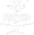
- FIG. 1depicts, in an exploded view, an exemplary artificial tree apparatus with multi-channel signals distributed via the tree column.
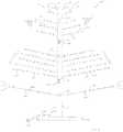
- FIG. 2depicts exemplary first and second trunk segments longitudinally aligned for connection.
- FIG. 3depicts an exemplary branch segment for coupling to a trunk segment with a user interface.
- FIG. 4depicts another exemplary branch segment for coupling to a trunk segment with a user interface.
- FIG. 5depicts an exemplary controller used in a control system for outputting independent multi-channel signals.
- FIG. 6depicts another exemplary system for processing independent multi-channel signals.
- FIGS. 7A-7Bdepict an exemplary orientation-independent multi-channel signal interface connection assembly.
- FIGS. 8A, 8B, and 8Cdepict another exemplary orientation-independent multi-channel signal interface connection assembly.
- FIGS. 9A, 9B, 9C, and 9Ddepict an exemplary self-aligning multi-channel signal interface connection assembly.
- FIGS. 10A, 10B, 10C, and 10Ddepict another exemplary self-aligning multi-channel signal interface connection assembly.
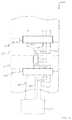
- FIG. 11depicts an exemplary multichannel distribution system integrated in a central pole.
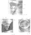
- FIGS. 12, 13, 14, 15, and 16depict schematically exemplary trunk segment configurations for distributing operating power and serial control commands to individual light string elements.
- FIGS. 1-2an exemplary artificial tree featuring multi-channel axial electrical interfaces and multi-channel signal path(s) integrated within the central pole is briefly introduced with reference to FIGS. 1-2 .
- FIGS. 3-4exemplary user interfaces that permit selection of a preferred light pattern channel for singular or group of branch segments are described.
- FIG. 5an exemplary embodiment of a controller in FIG. 5 .
- FIG. 6further explanatory discussion is presented to explain exemplary processing of multi-channel signal(s) received from the controller.
- FIGS. 7A-10Dvarious orientation-independent and self-aligning connection assemblies are illustrated for use with a single or multi-channel artificial tree apparatus.
- An exemplary multichannel systemis described with reference to FIG. 11 .
- FIGS. 12-16depict exemplary configurations for distributing operating power and serial control commands to individual light string elements.
- FIG. 1depicts, in an exploded view, an exemplary artificial tree apparatus with multi-channel signals distributed via the tree column.
- An artificial tree apparatus 100provides decoration and dynamic, complex, time-varying, multi-channel illumination.
- the artificial tree apparatus 100is in the shape of a Christmas tree, although the loads could be applied to another decoration, edifice, or substrate.
- the artificial tree apparatus 100 of this examplemay be of various heights, such as for example 2, 3, 4, 5, 6, 7, or 8 feet in overall height.
- the artificial tree apparatus 100includes a base 105 for providing self-standing upright support of the artificial tree apparatus 100 .
- the base 105may be secured rigidly to a floor surface.
- the base 105may be movable along the floor surface.
- the base 105may rotate the tree about its longitudinal axis. In such event, the electrical contact may be maintained, for example, via slip ring contacts, to avoid twisting of an electrical cord.
- Extending vertically from the base 105is a plurality of trunk segments 110 , 115 , 120 , 125 .
- the number of trunk segments 110 , 115 , 120 , 125may depend upon the overall height preference of the artificial tree apparatus 100 . In some exemplary embodiments, only 2-3 trunk segments may be used. In other exemplary embodiments, 4-6 trunk segments may be used to achieve a greater overall height of the artificial tree apparatus 100 .
- the length of each trunk segment 110 , 115 , 120 , 125may be the same in some exemplary embodiments.
- the trunk segments 110 , 115 , 120 , 125may employ a circular cross-section in some exemplary embodiments.
- the circular cross-section of the trunk segments 110 , 115 , 120 , 125permits the trunk segments to be connected in any radial orientation relative to the connecting trunk segments 110 , 115 , 120 , 125 that are being connected in a non-radial dependent manner.
- cross-sectional shapesmay provide for a more limited connection arrangement.
- a square cross-sectional shape of the trunk segmentswould only permit 4 radially different positions of adjacent-connecting trunk segments. Examples that incorporate orientation-dependent alignment of trunk segments are described with reference, for example, to at least FIG. 2 of U.S. Pat. No. 8,053,042, to Loomis, J., the entire contents of which are incorporated herein by reference.
- trunk segments 110 , 115 , 120 , 125may be shorter or longer than other trunk segments 110 , 115 , 120 , 125 to achieve a desired visual and/or lighting effect.
- the trunk segments 110 , 115 , 120 , 125may be assembled in a preferred order of emitted light pattern.
- Different trunk segments 110 , 115 , 120 , 125may be pre-programmed (e.g., hard-wired or executing a programmed set of instructions stored on a data store) to output a different predetermined light pattern scheme, for example.
- Such schemesmay involve a visually perceptible effect based on, for example, a combination of spectral, temporal (e.g., phase, frequency), and modulation waveform differentiations.
- a first trunk segmentmay be configured to output green light
- a second trunk segmentmay be configured to output red light
- a third trunk segmentmay be configured to output blinking white light, for example.
- the term “light pattern” hereinmay refer to various lighting effects, such as for example the light color, the light hue, the light increasing or decreasing brightness or intensity, the light on/off sequence, such as blinking fast, blinking slow, or other lighting effects such as simply turning the light on or off.
- each trunk segment 110 , 115 , 120 , 125includes an axial electrical connector 130 configured as a plug to mate with another axial electrical connector 135 configured as a socket.
- the trunk segments 110 , 115 , 120 , 125 and respective axial electrical connectors 130 , 135longitudinally align when being connected.
- the plug axial electrical connector 130may be oriented in any radial position relative the socket axial electrical connector 135 when connecting trunk segments 110 , 115 , 120 , 125 , thus being non-radial dependent.
- the artificial tree apparatus 100becomes easy and quick to assemble.
- the axial symmetrypermits the user a degree of freedom to independently adjust the relative angle between any of the segments 110 - 125 , as may be desired by the user.
- each trunk segment 110 , 115 , 120 , 125Extending from each trunk segment 110 , 115 , 120 , 125 are one or more branch segments 140 , 145 , 150 , 155 .
- the branch segments 140 , 145 , 150 , 155are shaped to resemble tree limbs.
- the branch segments 140 , 145 , 150 , 155may be shaped to resemble Pine tree boughs.
- each branch segment 140 , 145 , 150 , 155includes one or more integral light emitting devices 160 , 165 , 170 , 175 for emitting a light pattern.
- the light emitting devices 160 , 165 , 170 , 175may include light emitting diodes (LEDs).
- the light emitting devices 160 , 165 , 170 , 175may include incandescent bulbs.
- Each load of the light emitting devices 160 , 165 , 170 , 175may be configured to emit a predetermined light patterns that may be different (e.g., independent) with respect to the other light emitting devices 160 , 165 , 170 , 175 on the same or different branch segment 140 , 145 , 150 , 155 .
- a first group of lighting devices 160 on a first group of branch segments 140may output a slow blinking light pattern in a red color.
- a second group of lighting devices 165 on a second group of branch segments 145may output a fast blinking light pattern in a blue color.
- a third group of lighting devices 170 on a third group of branch segments 150may output an alternately increasing and decreasing intensity green light pattern.
- a fourth group of lighting devices 175 on a fourth group of branch segments 155may output a non-periodic (e.g., constant) white light pattern.
- the branch segment 140 , 145 , 150 , 155may be removed from the trunk segment 110 , 115 , 120 , 125 and a replacement branch segment may be connected.
- the artificial tree apparatus 100includes a control system 180 to generate and transmit command signals to the light emitting devices 160 , 165 , 170 , 175 .
- the control system 180may include a controller located at (or within) the base 105 of the artificial tree apparatus 100 .
- the command signalsmay be sent through internal wiring extending within the trunk segments 110 , 115 , 120 , 125 and the branch segments 140 , 145 , 150 , 155 to the light emitting devices 160 , 165 , 170 , 175 .
- the axial electrical connectors 130 , 135provide a pathway between trunk segments 110 , 115 , 120 , 125 for the command signals, which may include power, data, and/or control signals in analog and/or digital formats.
- control system 180is located within the base 105 of the artificial tree apparatus 100 .
- the control system 180permits independent operation of the light emitting devices 160 , 165 , 170 , 175 .
- control system 180generates and transmits a first command signal that is transmitted to a first group of light emitting devices 160 upon the first branch segments 140 and generates a separate and distinct command signal that is transmitted to a second group of light emitting devices 165 upon the second branch segments 145 .
- a power cord 185 and plug 190is shown to provide power to the light emitting devices 160 , 165 , 170 , 175 and to the control system 180 .
- AC power received by the power cord 185 and plug 190may be converted to low voltage DC power and then delivered to the light emitting devices 160 , 165 , 170 , 175 .
- the low voltage DC powercauses the light emitting devices 160 , 165 , 170 , 175 to illuminate at the pre-determined light pattern.
- a battery packmay be provided to power the control system 180 and/or the light emitting devices 160 , 165 , 170 , 175 .
- the artificial apparatus 100provides a coupling arrangement of the trunk segments 110 , 115 , 120 , 125 to permit independent relative rotation of adjacent connecting trunk segments 110 , 115 , 120 , 125 thus permitting easy connection in that the adjacent trunk segments 110 , 115 , 120 , 125 may be connected at and operate from any radially angular position relative to each other and to the longitudinal axis. Additionally, the coupling arrangement provides for electrical current and other important command information to be carried via internal pathways and connectors 130 , 135 extending within and from each of the trunk segments 110 , 115 , 120 , 125 .
- FIG. 2depicts exemplary first and second trunk segments longitudinally aligned for connection.
- a first trunk segment 200is configured to electrically and mechanically attach to a second trunk segment 205 while permitting the first trunk segment 200 to be positioned at any radial angle (e.g., non-radial dependent) relative to the second trunk segment 205 and still employ a secure electrical and mechanical connection.
- the trunk segmentsare substantially aligned and symmetric with respect to a longitudinal axis.
- the first trunk segment 200may be positioned at a 0 degree radial angle relative to a reference point upon the second trunk segment 205 .
- the first trunk segment 200may be positioned at a 90 degree radial angle relative to the same reference point upon the second trunk segment 205 and still employ the same electrical and mechanical connection as the relative 0 degree angle connection.
- the first trunk segment 200includes a hollow sleeve 210 extending from one end.
- the sleeve 210extends along a longitudinal axis of the first trunk segment 200 .
- Extending from the first trunk segment 200 within the sleeve 210is a first axial electrical connector 215 in the shape of a (male) plug.
- the first axial electrical connector 215is concentric with the sleeve 210 to permit free radial rotation about the longitudinal axis and relative the second trunk segment 205 during or after attachment.
- the first axial electrical connector 215includes a plurality of contacts 220 , 225 , 230 , each separated by an insulator 235 .
- Each contact 220 , 225 , 230may be configured to carry an independent electrical signal.
- a first contact 220is configured to carry a power signal
- a second contact 225is configured for ground (e.g., signal return)
- a third contact 230is configured to carry an electrical command signal representative of a light pattern.
- the longitudinally recessed location of the first axial electrical connector 215 within the sleeve 210protects the first axial electrical connector 215 from damage during assembly, disassembly, and storage of the trunk segments 200 , 205 , and ensures proper coaxial alignment of the axial electrical connector 215 prior to engagement.
- the overlapping stability of the cylindrical walls of the corresponding trunk segments 200 , 205provides greater strength and stability to the coupled trunk segments 200 , 205 of the artificial tree apparatus when installed.
- the second trunk segment 205includes a diametrically recessed portion 240 along an end which has a lesser outer diameter than the inner diameter of the sleeve 210 of the first trunk segment 200 such that the recessed portion 240 is received within the sleeve 210 .
- Extending inwardly from the end of the second trunk segment 205is a second axial electrical connector 245 in the shape of a (e.g., female) socket for receiving the first axial electrical connector 215 .
- the first axial electrical connector 215 of the first trunk segment 200is recessed some distance from the end of the first trunk segment 200 and within the internal cavity of the sleeve 210 so that the first trunk segment 200 can slide onto the recessed portion 240 of the second trunk segment 205 and engage the second trunk segment 205 to mate the first axial electrical connector 215 with the second axial electrical connector 245 of the second trunk segment 205 .
- the reduced diameter recessed portion 240 of the second trunk segment 205can freely rotate within the sleeve 210 of the first trunk segment 200 even when the first and second axial electrical connectors 215 , 245 are fully coupled together.
- the second axial electrical connector 245includes a corresponding plurality of contacts 250 , 255 , 260 to electrically connect with respective contacts 220 , 225 , 230 of the first axial electrical connector 215 .
- the provision of single or multiple channels carried on the single axial plug of the first axial electrical connector 215 and the corresponding axial socket of the second axial electrical connector 245enables free rotation of the axial electrical connectors 235 , 245 , obviating the need to rotationally align the trunk segments 200 , 205 prior to assembly of the artificial tree apparatus.
- releasable galvanic communicationmay be made between corresponding contact terminals of the connectors 215 , 245 by, for example, by employing compliant contacts that provide adjustable radial depth to accommodate axial connection and disconnection.
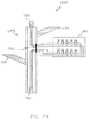
- FIG. 3depicts an exemplary branch segment for coupling to a trunk segment with a user interface.
- a trunk segment 300is shown having a user interface 305 with a first radial receptacle 310 , a second radial receptacle 315 , and third radial receptacle 320 .
- the first radial receptacle 310may connect to a first signal wire internal to the trunk segment 300 that is configured to carry a first electrical command signal.
- the second radial receptacle 315may connect to a second signal wire internal to the trunk segment 300 that is configured to carry a second electrical command signal.
- the third radial receptacle 320may connect to a third signal wire internal to the trunk segment 300 that is configured to carry a third electrical command signal.
- the electrical command signalsmay be different from each other to represent different light patterns.
- Each branch segment 325may be connected to a preferred radial receptacle 310 , 315 , 320 thus permitting different branch segments 325 to emit different light patterns by the respective electrical command signals.
- the radial receptacles 310 - 320may carry a plurality of signals, for example, including power and at least one data signal containing encoded information associated with a command signal for modulating the load output intensity, for example.
- the first electrical command signalmay be representative of a first light color
- the second electrical command signalmay be representative of a second light color
- the third electrical command signalmay be representative of a third light color
- the first electrical command signalmay be representative of a blinking light
- the second electrical command signalmay be representative of a solid light
- the third electrical command signalmay be representative of a modulating light.
- a radial plug 330extends from the branch segment 325 .
- the branch segment 325may include a branch member 335 to mimic the shape of a tree branch.
- the branch segment 325has one or more light emitting devices 340 .
- the radial plug 330is connected via insertion to the user-selected radial receptacle 310 , 315 , 320 that is configured to emit the preferred electrical command signal. If a different electrical command signal is later preferred, the radial plug 330 may be removed from the radial receptacle 310 , 315 , 320 currently in use and reinserted into a different radial receptacle 310 , 315 , 320 .
- a control systemmay be configured to output a different electrical command signal to the corresponding group of radial receptacles 310 , 315 , 320 .
- the user interface 305 and radial receptacles 310 , 315 , 320form a portion of the control system.
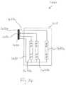
- FIG. 4depicts another exemplary branch segment for coupling to a trunk segment with a user interface.
- a trunk segment 400is shown having a radial receptacle 405 and a user interface 410 comprising a multi-position control switch 415 .
- the control switch 415includes a first position, a second position, a third position, and a fourth position.
- the first positionmay be representative of a first electrical command signal
- the second positionmay be representative of a second electrical command signal
- the third positionmay be representative of a third electrical command signal
- the fourth positionmay be representative of a fourth electrical command signal.
- a branch segment 420 having a radial plug 425is aligned with the radial receptacle 405 .
- the branch segment 420includes a branch member 430 for carrying one or more light emitting devices 435 .
- the radial plug 425is connected via insertion to the radial receptacle 405 .
- the control switch 415 positionis adjusted to output a corresponding electrical command signal to the light emitting devices 435 upon the branch segment 420 . If the light pattern is desired to be changed, the control switch 410 may be adjusted to output a different electrical command signal.
- a control systemmay be configured to correspond one or more of the control switch 410 positions with an alternative electrical command signal corresponding to a different light modulation or pattern.
- the user interface 410 and radial receptacle 405may form a portion of the control system.
- the user interface 415alone or integrated with a controller, may advantageously be disposed at a convenient height for access by a user in a standing position, which may be, for example, one meter or more above the floor on which the base is resting.
- the controllermay be hidden by decorative or ornamental items on or proximate the controller housing.
- FIG. 5depicts an exemplary controller used in a control system for outputting independent multi-channel signals.
- a controller 500is shown which may form an entire or a portion of a control system used to generate, process, and/or transmit one or more channels of command signals for distribution via the central trunk segments to loads, which may include light strings capable of illuminating light patterns in response to the command signals.
- the controller 500includes a power input and a ground input that may lead to a power switch 505 controlled by user input.
- the power input signalmay be AC or DC.
- the controller 500may include an AC to DC converter to convert the input power. Further power conditioning may be incorporated, for example, to provide appropriate filtering, power factor correction, electromagnetic interference suppression/mitigation, and/or attenuation or boosting, as appropriate for the application.
- outputs of the controllermay be configured to regulate or limit current and/or voltage supplied to a particular load.
- an upstream controller 500may control operation of the power switch 505 .
- Output from the controller 500includes a DC output and a ground output.
- the DC outputmay pass-through and be substantially the same amplitude as the Power Input (DC) voltage such that the DC passes-through the controller 500 without being substantially attenuated.
- the power switch 505may be omitted.
- the controller 500 depicted in this exampleis programmable and includes a processor 510 (e.g., CPU), random access memory (RAM) 515 , non-volatile memory (NVM) 520 which may have embedded code 525 , and a communications port 530 .
- the processor 510may receive and execute the code 525 to perform various digital or analog control functions.
- the processor 510may be a general purpose digital microprocessor 510 which controls the operation of the controller 500 .
- the processor 510may be a single-chip processor 510 or implemented with multiple components. Using instructions retrieved from memory, the processor 510 may control reception and manipulations of input data and the output data or excitation signals.
- RAMmay be used by the processor 510 as a general storage area and as scratch-pad memory, and can also be used to store input data and processed data.
- the exemplary controller 500also includes a user interface 540 controlled by user input and an analog interface 545 controlled by analog input.
- the user interface 540may include dials, such as for example timing dials, frequency dials, or amplitude control dials.
- the user interface 540may include switches or control buttons, such as for example amplitude changing controls, channel changing controls, or frequency changing controls.
- the switches or control buttonsmay correspond to various light patterns that may involve, for example, light colors, modulation patterns (e.g., pulsed, triangular, sinusoidal, or rectangular waveforms), light intensities, or light blinking rates.
- the user interface 540 and the analog interface 545as well as the processor 510 , memory, and communications are connected to a control module 550 .
- a communications network 535may communicate with the communications port 530 and may be utilized to send and receive data over a network 535 connected to other controllers 500 or computer systems.
- An interface card or similar device and appropriate softwaremay be implemented by the processor 510 to connect the controller 500 to an existing network 535 and transfer data according to standard protocols.
- the communications network 535may also communicate with upstream or downstream controllers 500 , such as for example to activate or deactivate upstream or downstream controllers 500 .
- the communications network 535may be suited for routing master-slave commands to or from the downstream controller 500 .
- controllers 500may include suitable circuitry for interpreting the master-slave command Commands sent to upstream or downstream controllers 500 may be sent through power line carrier modes, optical (e.g., infrared, visible), sound (e.g., audible, ultrasonic, subsonic modulation), or wireless (e.g., Bluetooth, Zigbee) modes, for example.
- power line carrier modesoptical (e.g., infrared, visible), sound (e.g., audible, ultrasonic, subsonic modulation), or wireless (e.g., Bluetooth, Zigbee) modes, for example.
- the exemplary control module 550includes a plurality of function generators 555 , 560 , 565 each for outputting one or more predetermined or user-configured waveforms to a corresponding channel.
- the function generators 555 , 560 , 565may operate independently of one another.
- the function generators 555 , 560 , 565may operate with, for example, different temporal, phase shift, or waveforms aspects.
- some or all of the function generators 555 - 565may be synchronized to each other, or to external clock source signal, for example.
- the function generators 555 , 560 , 565may receive pre-stored data for outputting predetermined waveforms or may receive user-configured data from user input to generate unique and customizable waveforms.
- the waveforms generatedmay be electrical waveforms which control and regulate output lumens from one or more lights upon a light string.
- the control module 550may also include a switch timing control 570 which may use a duty cycle to generate control signals for use by the function generators 555 , 560 , 565 .
- the control signalsmay be timed to produce predetermined current waveforms at predetermined frequencies or intervals.
- exemplary composite effectsmay include, but are not limited to, walking, waterfall, random, or a combination of such effects.
- the waveforms generated by the function generators 555 , 560 , 565may comprise one or more frequencies.
- the waveforms generatedmay cause a blinking effect among the connected lights.
- the waveforms generatedmay cause a steady-on effect among the connected lights.
- the waveforms generatedmay cause a dimming effect among the connected lights.
- the waveforms generatedmay cause a dimming effect followed by a steady-on effect among the connected lights.
- the waveforms generatedmay cause a blinking effect followed by a dimming effect followed by a steady-on effect among the connected lights.
- FIG. 6depicts another exemplary system for processing independent multichannel signals.
- a control system 600includes a main controller 605 and a plurality of multiplexers 610 , 615 that may receive addressed command signals from the main controller 605 and output electrical command signals, for example as via a buffer or a pass-through.
- the first multiplexer module 610 and associated circuitryis electrically connected to radial receptacles 620 on a first trunk segment 625 .
- a second multiplexer module 615 and associated circuitryis electrically connected to a radial receptacle 630 on a second trunk segment 635 .
- the trunk segments 625 , 635may be electrically connected via the exemplary axial electrical connectors 640 , 645 .
- Each multiplexer 610 , 615is in signal communication with the controller 605 via a command wire 650 and a plurality of channel wires 655 , 660 , 665 .
- the command wires 650may carry an electrical command signal indicative of a command for a specific addressed multiplexer 610 , 615 to read and transmit a specific channel wire 655 , 660 , 665 .
- Power and ground wiresmay also be incorporated within one or more of the command or channel wires 650 , 655 , 660 , 665 , or incorporated as stand-alone wires to provide power to the light emitting devices and internal circuitry.
- the wires and circuitryare located internal to the trunk segments 625 , 635 and may be internal or be routed along axial electrical connectors 640 , 645 connecting the trunk segments 625 , 635 .
- the command wire 650may also serve as a power delivering signal from a low impedance source so as to deliver operating voltage and current to supply one or more load devices.
- the multiplexer modules 610 , 615may each be equipped with frequency selective receivers that can detect demodulate command signals that are modulated on top of the power line power delivering signal, which may be low voltage DC, for example, or 60 Hz AC, for example, as carried on the command wire 650 .
- a suitable frequency selective receivermay include an analog filter, a digital filter implemented in hardware, a digital filter implemented in software, or a combination of these, to selectively detect and extract a modulated command signal on the carrier power signal.
- Various modulation schemesmay be used, including but not limited to phase, frequency, or amplitude modulation.
- Each multiplexer 610 , 615may be assigned a predetermined unique address for selectively determining which signal commands to react to.
- the first multiplexer 610may have address 0001 and the second multiplexer 615 may have address 0002.
- each channel wire 655 , 660 , 665may have a distinct address, such as “A”, “B”, and “C” for example.
- the main controller 605may send a serial command signal along the command wire 650 , such as 0001A0002B for example.
- the command signalmay be interpreted by the multiplexer 0001 illustrated as the first multiplexer 610 to read channel wire “A” illustrated as wire 655 and transmit the respective command signal on wire “A” to the connected light emitting devices since address “A” follows the address of the first multiplexer 610 . Since channel address “B” follows the multiplexer address 0002 illustrated as multiplexer 615 , the second multiplexer 615 may be programmed to read channel wire “B” illustrated as wire 660 and transmit the respective electrical signal carried on channel wire “B” to the connected light emitting devices.
- control schememay dynamically control the routing of signals on any of wires 655 - 665 to any selected load, such as the loads connected to any selected one of the radial receptacles 620 , 630 .
- control schemesmay be implemented by operation of a controller, an example of which is described with reference to FIG. 5 .
- the main controller 605may be configured to send out an electrical command signal referencing only the multiplexer 610 , 615 that was changed. For example, if the second multiplexer 610 were changed to read and transmit channel “C” illustrated by wire 665 via a control switch or other adjustment device, the main controller 605 may transmit an electrical command signal having data 0002C. Since the electrical command signal does not reference multiplexer 0001, the first multiplexer 610 ignores the command and the command is only read and acted upon by the second multiplexer 615 addressed 0002.
- Various embodimentsinclude exemplary addressing schemes that may be illustrative of the flexible configurations achievable with a multi-channel system with signal distribution in a trunk signals.
- information and/or command signalsmay be conveyed axially via an optical path.
- information and/or command signalsmay be coupled between trunk segments using galvanically-isolated electrical ports, for example, formed of magnetic flux coupling (e.g., transformer coupling), capacitive coupling, optical coupling, either alone or in some combination.
- FIGS. 7A-7Bdepict an exemplary orientation-independent multi-channel signal interface connection assembly.
- a connection assemblyincludes a first connector 700 and a second connector 705 .
- the first connector 700 and the second connector 705may be formed integrally with the trunk segments and/or the branch segments as described herein to permit connection of trunk segments and/or branch segments in any radial orientation relative to each other.
- Also shownare a series of first electrical connectors 710 extending from the first connector 700 and a second electrical connector 715 formed within the second connector segment 705 .
- the first electrical connectors 710may be formed of a male-plug type and the second electrical connector 715 may be formed of a female plug type.
- the connectors 710may be spring-based pins that can adjust to small imperfections in the depth of the coupling connection to between the connector 705 and the connector 715 .
- the second electrical connector 715may include an electrically conductive medium 720 for electrically receiving the first electrical connectors 710 and permitting the first electrical connectors 710 to be received within the second electrical connector 715 in any radial orientation.
- axially symmetric concentric conductive rings 720are separated by axially-symmetric concentric non-conductive separator rings.
- a distal tip of each of the connectors 710fits within or between adjacent separator rings to substantially prevent electrical shorting.
- the conductive rings 720may be formed of a conductive gel substance, or a conductive metal (e.g., by way of example and not limitation, copper, nickel, brass, gold or a combination thereof).
- each first electrical connector 710may transmit a different electrical signal.
- FIGS. 8A-8Cdepict another exemplary orientation-independent multi-channel signal interface connection assembly.
- FIG. 8Adepicts an exemplary first connector 800 .
- FIG. 8B and FIG. 8Cdepict an exemplary sectional view and an exemplary upper perspective view of a second connector 805 .
- the first connector segment 800 and the second connector segment 805may be formed integrally with the trunk segments and/or the branch segments, respectively, as described herein to permit connection of trunk segments and/or branch segments in any radial orientation relative each other.
- Also shownare a series of first electrical connectors 810 extending from the first connector segment 800 and a second electrical connector 815 formed within the second connector segment 805 .
- the first electrical connectors 810may be formed of a male-plug type and the second electrical connector 815 may be formed of a female plug type.
- the second electrical connector 815may include an electrically conductive medium 820 for electrically receiving the first electrical connectors 810 and permitting the first electrical connectors 810 to be received within the second electrical connector 815 in any radial orientation.
- the conductive medium 820may be formed of a conductive gel substance.
- each first electrical connector 810may transmit a different electrical signal (e.g., power, commands, information), such as a different signal channel.
- FIGS. 9A-9Ddepict an exemplary self-aligning multi-channel signal interface connection assembly.
- FIG. 9A and FIG. 9Bdepict an exemplary first connector 900 in plan and perspective side views.
- FIG. 9C and FIG. 9Ddepict an exemplary top view and an exemplary sectional view of a second connector 905 .
- the first connector segment 900 and the second connector segment 905may be formed integrally within the trunk segments and/or the branch segments as described herein to permit connection of trunk segments and/or branch segments in a self-aligning manner.
- Also shownare a series of first electrical connectors 910 extending from the first connector segment 900 and a guide 915 leading to a series of second electrical connectors 920 formed within the second connector segment 905 .
- the first electrical connectors 910may be formed of a male-plug type and the second electrical connector 920 may be formed of a female plug type.
- the guide 915forces the male end of the first connector segment 900 to be rotated towards a pre-determined angle with respect to a longitudinal axis when being inserted within the second connector segment 905 .
- the guide 915has curved or angled interior edges so that the first connector segment 900 slides into the second connector segment 905 smoothly and without obstruction.
- the second electrical connector 920may comprise an electrically conductive medium 920 for electrically receiving the first electrical connectors 910 and permitting the first electrical connectors 910 to be received within the second electrical connector 920 .
- the conductive medium 920may be a conductive gel substance.
- each first electrical connector 910may transmit a different electrical signal.
- FIGS. 10A-10Ddepict another exemplary self-aligning multi-channel signal interface connection assembly.
- FIG. 10A and FIG. 10Bdepict an exemplary first connector 1000 in a side perspective view and a sectional view.
- FIG. 10C and FIG. 10Ddepict an exemplary bottom view and an exemplary top view of a second connector 1005 .
- the first connector segment 1000 and the second connector segment 1005may be formed integrally with the trunk segments and/or the branch segments as described herein to permit connection of trunk segments and/or branch segments in a self-aligning manner.
- Also shownare a series of first electrical connectors 1010 extending from the first connector segment 1000 and a guide 1015 leading to a series of second electrical connectors 1020 formed within the second connector segment 1005 .
- the first electrical connectors 1010may be formed of a male-plug type and the second electrical connector 1020 may be formed of a female plug type.
- the guide 1015forces the male end of the first connector segment 1000 to be rotated towards a pre-determined rotation when being inserted within the second connector segment 1005 .
- the guide 1015has curved or angled interior edges so that the first connector segment 1000 slides into the second connector segment 1005 smoothly and without obstruction.
- the second electrical connector 1020may comprise an electrically conductive medium 1020 within for electrically receiving the first electrical connectors 1010 and permitting the first electrical connectors 1010 to be received within the second electrical connector 1020 .
- the conductive medium 1020may be a conductive gel substance.
- each first electrical connector 1010may transmit a different electrical signal.
- FIG. 11depicts an exemplary multichannel distribution system integrated in a central pole.
- a multichannel distribution system 1100includes pole sections 1105 A, B, C, through which multichannel signal conductors are routed from a base 1110 . Extending from the base 1110 is a signal conductor coupled to an interface 1115 . The signal conductor between the base 1110 and the interface 1115 may conduct, for example, power and/or one or more channels of information signals.
- the pole section 1105 acouples to the pole section 1105 b via an interface 1120 , which is shown in the magnified view to reveal additional details.
- the pole sections 1105 Bcouples to the pole section 1105 C
- the pole section 1105 Ccouples to the base 1110 via interfaces substantially similar to the interface 1120 .
- the interface 1120includes a multi-channel socket 1125 to receive and provide signal communication to corresponding channels in a plug 1130 .
- the multi-channel signalsmay communicate to radial ports 1135 distributed along the length of the pole sections 1105 A-C.
- the radio port 1135is depicted in this example as receiving a radial plug assembly 1140 , which may be connected to a load and/or a single or multi-channel signal source.
- adjacent pole sectionsmay be securely coupled by a collar 1145 engaging threads 1150 .
- the pole section 1105 Aincludes an output connector 1160 at which some or all of the multichannel signals may be made available to an external load device and/or a controller. In various embodiments, one or more of the output connectors 1160 may be made available, for example, within the base 1110 and/or any of the other pole sections 1105 .
- FIGS. 12-16depict schematically exemplary trunk segment configurations for distributing operating power and serial and/or parallel control commands to individual light string elements.
- FIG. 12depicts a light string with power, return, and data lines extending between two opposing connectors for releasably plugging into a trunk segment to form a loop that can be distributed on the branches of the tree, for example.
- FIG. 13depicts an end-in-bulb light string with power, return, and data lines exiting via an aperture in each trunk segment, with the data signal looping back to re-enter the trunk segment through the same aperture.
- FIG. 14depicts an embodiment similar to that of FIG.
- FIG. 15depicts a light string similar to the one of FIG. 12 , with the addition of an additional control line (e.g., clock signal) that is distributed to each individually addressable illumination module, so as to accommodate serial data systems that require a clock input signal.
- FIG. 16depicts a light string with at least 3 parallel current paths independently driven by an independent command signal.
- an artificial tree apparatus 1200includes first and second trunk segments 1205 a , 1205 b , which may be connectable, for example, when aligned in an orientation independent manner along a longitudinal axis (e.g., vertical axis).
- the trunk segments 1205 a,bare adorned with radially extending branches 1210 at various locations along each of the segments.
- the artificial tree apparatus 1200is illuminated with decorative light string assemblies 1215 a , 1215 b , associated with the trunk segments 1205 a , 1205 b , respectively.
- Each of the light string assemblies 1215 a,bincludes a number of individually operable illumination modules 1220 a , 1220 b .
- Each of the illumination modules 1220 a,b in this exampleis an individually addressable light engine, responsive to an independent, serially-addressed command signal targeting that individual illumination module 1220 a,b .
- at least some of the individual illumination modules 1220 a,bmay include a cascadable LED driver chip, such as the WS2811, commercially available from Worldsemi Co., Limited of China.
- the LED driver chipmay be addressable, and send and receive serial commands from and to adjacent illumination modules 1220 a,b along either of the light assemblies 1215 a,b .
- Each such driver chipmay control illumination of one or more luminaires, such as a red, green, or blue (RGB), for example, in the illumination module 1220 a,b in response to a received serial command signal.
- the illumination modules 1220 a,beach receive an operating power signal 1225 , a circuit return 1230 (e.g., ground, or circuit reference potential), and a command signal 1235 .
- the command signal 1235may be a single wire configured to distribute a serial command signal, or 2 or more wires to provide command signals in the form of data, control, and/or clock signals, for example.
- the light string assemblies 1235 a,bextend between connectors 1240 a,b and 1245 a,b , respectively.
- the connectors 1240 a,b and 1245 a,bare releasably pluggable to make electrical connection to respective trunk segment connectors 1250 a,b and 1255 a,b .
- the light string assembly 1215 a,bmay provide an electrical channel for a female trunk segment connector 1260 a,b to transmit operating power 1225 , the circuit return 1230 , and serially addressable command signals 1235 to a male trunk segment connector 1265 a,b at an opposite end of the trunk segment 1205 a,b .
- the operating power 1225 , the circuit return 1230 and the command signal 1235may be routed from the female trunk segment connector 1260 a of the first segment, through the lights string assemblies 1215 a,b , and to the male trunk segment connector 1265 b of the second trunk segment 1205 b . From there, one or more subsequent trunk segments (not shown) may be connected, and the operating power 1225 , the circuit return 1230 and the command signal 1235 may be routed via the trunk segments and made available to operate additional loads, such as downstream light strings, controllers, and/or other loads.
- a number of the branches 1210may be distributed at numerous locations around the trunk segments 1205 a,b . There may be more than one light string assembly in each trunk segment 1205 a,b .
- the connectors 1260 a,b and 1265 a,bmay be, for example, self-aligning, examples of which are described with reference to FIGS. 7A-10D .
- FIG. 13depicts an end-in-bulb light string 1315 a,b with power 1325 a,b , circuit return 1330 a,b , and data 1335 a,b lines exiting via an aperture in each trunk segment, with the data 1335 a,b line looping back to re-enter the trunk segment through the same aperture 1350 a,b .
- An internal connection from the power and circuit returnmay extend directly between the female trunk segment connector 1260 a,b and the male trunk segment connector 1265 a,b .
- the data line 1335 a,bpasses serially through the light string 1315 a,b , respectively.
- a serial command signal transmitted by the controller (not shown) over the serial data line 1335 a,bmay include a first signal addressed to be received and accepted by one or more of the individual light illumination modules in the light string 1315 a , while a second signal in that same serial command may be received and accepted by one or more of the individual light illumination modules in the light string 1315 a .
- the second signalmay be independent from the first signal.
- the first and second light strings 1315 a,bmay execute the first and second signals substantially simultaneously in response to the same serial command signal.
- FIG. 14depicts an embodiment similar to that of FIG. 12 , except the ends of the light string 1415 are integrally connected inside the trunk segment 1405 rather than pluggably connected. Both ends of the light string 1415 enter and exit the trunk segment through a common aperture, for example.
- FIG. 15depicts a light string 1515 similar to the one of FIG. 12 , with the addition of an additional control line (e.g., clock signal 1535 b ) that is distributed to each individually addressable illumination module, so as to accommodate serial data systems that operate synchronously, or with a clock input signal, in coordination with a serial data signal 1535 a .
- an additional control linee.g., clock signal 1535 b
- the power 1525 , circuit return 1530 , the data 1535 a , and clock 1535 bextend between two opposing end connectors 1540 and 1545 .
- the connector 1540is plugged in to the trunk segment (not shown), the connector 1545 is available to supply the power 1525 , circuit return 1530 , the data 1535 a , and clock 1535 b to operate downstream loads, such as light strings, controllers, splitters, and peripheral loads, for example.
- FIG. 16depicts a light string with at least 3 parallel current paths independently driven by an independent command signal.
- FIG. 16depicts an exemplary light string 1615 with parallel circuits 1620 a,b,c driven respectively by, in this example, three independent command signals 1635 a,b,c that merge at a common return path 1630 .
- Each of the circuits 1620 a,b,cmay have a unique color scheme and/or spatial distribution, for example, to provide for lighting effects.
- One or more of the lighting elements in any of the circuits 1620 a,b,cmay be individually addressable by, for example, serial commands supplied on the corresponding command signals 1635 a,b,c.
- a light stringsuch as various ones of the light strings described with reference to FIGS. 12-16 , for example, may include a pass-through channel for operating power to be distributed from a connector at one end to a connector at an opposite end of the light string. Such pass through of operating power may advantageously deliver power to at least one downstream controller and/or peripheral device(s), for example, that may be connected to at least one subsequent light string or device.
- Some examples of light stringsmay include command signals in addition to pass through power, and may be adapted for connection to receive operating power and command signals from the inside one of the trunk segments.
- operating power levelsmay be at or beyond a maximum efficiency operating point, or a stable operating point (e.g., voltage out of range).
- some embodimentsmay further include a level shifting module in cascade-connected light strings, for example.
- the axial electrical connectorsmay be configured in other structural shapes.
- a first axial electrical connectormay be configured in the shape of a concentric ring extending along an outside of a first trunk segment and beyond an end of the first trunk segment.
- a corresponding end of a second trunk segmentmay include an axial electrical connector formed into the end for being received by the first axial electrical connector in an overlapping manner.
- each branch segmentmay be attached separately to the trunk segments during assembly of the artificial tree apparatus in some exemplary embodiments.
- one or more of the branch segmentsmay be pre-attached to the trunk segments to lessen assembly time of the artificial tree apparatus.
- the branch segmentsmay be pivotally attached to the trunk segments such that the branch segments are folded up during storage to minimize an overall surface area of the artificial tree apparatus and during assembly the branch segments folded downwards to mimic a tree.
- the branch segmentsmay be configured in various lengths.
- the branch segmentsmay be colored to match living trees or may incorporate other nontraditional colors, such as for example red, pink, blue, or white.
- each light emitting devicemay emit a pre-determined light pattern.
- each light emitting device in a branch segmentmay blink at a given rate, remain constant, or gain/loss intensity.
- some lighting devices on a branch segmentmay perform a first function while other lighting devices on the same branch segment may perform a second function, either simultaneously or at different times.
- a first lighting devicemay blink while a second lighting device may remain constant on, while a third lighting device may increase/decrease light intensity only when the first and second lighting devices remain off.
- a group of light emitting devicesmay collaborate together to emit the pre-determined light pattern.
- the light emitting devicesmay emit different patterns to follow a beat to a popular song.
- control systemmay comprise a single controller or a multitude of controllers.
- a single controllermay be located at the base of the artificial tree apparatus to generate and transmit command signals to respective light emitting devices upon the branch segments.
- each branch segmentmay include a slave controller and a master controller may be located proximate the base of the artificial tree apparatus.
- the slave controllersmay be located within the respective branch segments or trunk segments, for example.
- the axial electrical connectorsmay include more than three contacts, such as 4, 5, 6, or 7 contacts for example, where each contact may be configured to carry an independent signal.
- a first additional contactcarries a first electrical command signal
- a second additional contactcarries a second electrical command signal
- a third additional contactcarries a third electrical command signal.
- the first additional contactmay carry an electrical command signal representative of a blinking light pattern
- the second additional contactmay carry an electrical command signal representative of an alternately fading/constant light pattern
- the third additional contactmay carry an electrical command signal representative of a stepped light pattern. If a group of first lighting devices are configured to receive an electrical command signal from the first additional contact, the first lighting devices receive an electrical command signal representative of a blinking light pattern.
- the electrical command signalmay include different types of data pertaining to illumination.
- the command signalsmay include data pertaining to a light pattern.
- the command signalsmay include data pertaining to a light intensity, such as brightness of an outputted light.
- the command signalsmay include data pertaining to a light color.
- the electrical command signalmay include different types of data pertaining to sound.
- the command signalmay include data pertaining to a song or a musical note.
- some trunk segments or branch segmentsmay include speakers for outputting a sound received by the electrical command signal.
- apparatus and methodsmay involve a controller having a voice activated light controller.
- a command signalmay be generated based upon a voice command given to the controller. For example, a user may speak the words “blinking red channel 1,” and the controller would interpret the voice command, generate, and transmit an electrical command signal along channel 1 wire that causes the light emitting devices to output a red colored blinking pattern.
- a tangible on/off switchmay be incorporated into the controller and/or light emitting devices. For example, the user may turn the light emitting devices on and off via a special touch sensor ornament (e.g., a metal snowflake) that is permanently attached to the artificial tree apparatus.
- signal and power carrying wiresmay be strung internally through the trunk segments such that there will be no visibility of the signal and power carrying wires from an outside of the trunk segments.
- wireless transmissionmay be used to communicate a command signal to one or more light emitting devices.
- a wireless transmissionmay be used to communicate a command signal to a receiver local to the respective branch segment, where the branch segment then directs the command signal to the light emitting devices upon the respective branch segment via wired or wireless transmission.
- an electric motormay be incorporated into the base of the artificial tree apparatus to cause the artificial tree apparatus to rotate.
- a wireless remote controlpermits the user to turn the light emitting devices on and off, as well as turn the motor on and off.
- the motormay be connected to the base, such as for example to the top of the base through a plug and socket arrangement.
- a control systemmay generate a plurality of electrical command signals each intended for a specific group of light emitting devices on a singular branch segment or singular trunk segment.
- a first trunk segmentmay be configured to receive a first electrical command signal representative of a red blinking pattern.
- the red blinking patternmay be transmitted to each of the light emitting devices directly connected to the first trunk segment.
- a second trunk segmentmay be configured to receive a second electrical command signal generated by the control system and representative of a blue constant on pattern.
- the blue constant on patternmay be transmitted to each of the light emitting devices directly connected to the second trunk segment.
- load devicesmay include motors, audio transducers, light emitting diodes or other light emitting devices, for example, either alone or in combinations.
- a user-controlled switchmay be located upon each trunk segment for corresponding branch segments having load devices.
- a user-controlled switchmay be located next to each branch segment such that each trunk segment may have a plurality of user-controlled multi-position switches, for example.
- a specific command signalmay be associated with a specific radial receptacle such that each branch segment may be plugged into a pre-determined radial receptacle determined by the illumination pattern and color intended for the light emitting devices connected to the branch segment.
- one or more branchesmay be associated with a load circuit.
- One or more of the load circuitsmay include a group of light emitting devices.
- each group of light emitting devicesmay be manually configured via one or more user-interfaces.
- adjoining trunk segmentsmay couple via an axially-symmetric connection system that permits connection in any radial orientation relative to the longitudinal axis of the trunk or column.
- the control systemmay output a plurality of (e.g., electrical, optical) command signals. Each command signal may be, in some embodiments, intended for and/or addressed to a specific predetermined load.
- a communication signalmay be transmitted to the controller to command the controller to enter one of a plurality of user-selectable modes. Each mode may be associated with a corresponding illumination signal to be generated and transmitted to the light emitting devices.
- a wireless transmission having a command for an illumination signalmay be sent from a mobile device over a local or wide-area network to the controller.
- the controllermay then generate or relay the signal to the light emitting devices through the internal transmission wires within the trunk segments and along or through the branch segments.
- a multi-channel signalsmay include serial, multiplexed, and/or parallel techniques.
- a single conductive path within the tree columnmay carry an operating current (e.g., power/return, bias supply, etc. . . . ) and, in combination, a time and/or frequency division or multiplexed command or information signal.
- Multi-channel signals used to control, for example, a plurality of independent load circuits, for examplemay share a common conductive transmission path in addition to a common return path, for example.
- Multi-channel signalsmay include, by way of example, and not limitation, time-division multiplex, frequency division multiplex, space-division multiplex, amplitude modulation, frequency modulation, phase modulation, quadrature keying, and other known modulation techniques for encoding one or more independent signals.
- a power line carrier techniquecould be employed to control a plurality of independent loads with a two wire system that supplies operating current to all of the loads simultaneously.
- Commands to be performed at the load devicecan be formatted in 4 bit chunks to be received by the addressed decoder.
- voltage level output from a power supply controlled by the controllermay encode a command or information signal that can be detected using level detection circuits, which may be distributed in one or more multiplexer modules or signal routers, for example.
- Multi-channel signalsmay include electrical signals conducted via the tree column.
- multi-channel signalsmay also include signals or combinations of signals conveyed in various forms via the tree column.
- the tree columnmay convey commands, power, or other information signals via pneumatic, optical (e.g., light, infrared, UV, laser), fiber optic, mechanical (e.g., vibrational, push-rods), magnetic states, electrochemical mechanisms.
- Signal handling systems within the trunkmay include signal transport (e.g., fiber optic, conductor, semiconductor), signal processing (e.g., optical filtering, electromagnetic reflectors, addressable decoders), switching apparatus (e.g., multiplexers, decoders, magnetic switches, hall effect switches, semiconductor switches, logic gates, etc. . . . ), and interface apparatus (e.g., transducers, interconnects, transformers, optocouplers, manifolds, etc. . . . ).
- the first axial electrical connector 215may not be recessed within the first trunk segment 200 and the inter-segment coupling of the trunk segments 200 , 205 could be made solely by electrical connectors.
- a plurality of power, command, and/or information signalsmay be communicated via signal paths disposed within a central pole member, for example, in a household floor lamp.
- signal pathsdisposed within a central pole member, for example, in a household floor lamp.
- an artificial tree apparatusmay include a first trunk segment having a first axial electrical connector, and a second trunk segment having a second axial electrical connector.
- the second axial electrical connectoris adapted to longitudinally align and connect with the first axial electrical connector in a non-radial dependent manner.
- the apparatusfurther includes a first branch segment having a first light string replaceably disposable about the first branch segment. The first branch segment radially extends from the first trunk segment.
- a second branch segmenthas a second light string replaceably disposable about the second branch segment. The second branch segment radially extends from the second trunk segment.
- a control systemis configured to generate a first electrical command signal and a second electrical command signal.
- Operating power for the first and second light strings and the first and the second electrical command signalsare transmitted from the first trunk segment to the second trunk segment through connection of the first and second axial electrical connectors.
- the first light stringis configured to receive the first electrical command signal and the second light string is configured to receive the second electrical command signal.
- the first electrical command signalmay correspond to a first light pattern and the second electrical command signal may correspond to a second light pattern.
- the first light patternmay be different from the second light pattern.
- the first light patternmay include a first light color and the second light pattern may include a second light color.
- the first light patternmay include a visually perceptible visual light effect.
- the control systemmay include at least one user interface for altering the first electrical command signal or the second electrical command signal.
- the artificial tree apparatusmay include a first user interface and a second user interface.
- the first user interfacemay be adapted for operative route selection of the first electrical command signal or the second electrical command signal to the first light string.
- the second user interfacemay be adapted for operative route selection of the first electrical command signal or the second electrical command signal to the second light string.
- the first user interfacemay be located upon the first trunk segment and the second user interface may be located upon the second trunk segment.
- the first light stringmay be comprised of a first LED light string and the second light string may be comprised of a second LED light string.
- the apparatusmay further include a plurality of channel wires extending within the first trunk segment and the second trunk segment from the control system for transmitting the first electrical command signal and the second electrical command signal.
- the control systemmay be configured to wirelessly receive user input signals from a mobile device.
- the control systemmay select a user-selectable mode in response to the wirelessly received user input signals.
- an artificial tree apparatusmay include a first trunk segment having a first axial electrical connector, and a second trunk segment having a second axial electrical connector.
- the second axial electrical connectormay be adapted to longitudinally align and connect with the first axial electrical connector in a non-radial dependent manner.
- the apparatusfurther includes a first branch segment, wherein the first branch segment radially extends from the first trunk segment.
- a first light stringis replaceably disposable about the first branch segment.
- a second branch segmentradially extends from the second trunk segment.
- a second light stringis replaceably disposable about the second branch segment.
- a current path in the first trunk segmentconnects to supply operating power to the first light string and to the first axial connector.
- At least one current path in the first trunk segmentreceives a first electrical command signal and a second electrical command signal from a control system. Operating power and the second electrical command signals are transmitted from the first trunk segment to the second trunk segment when the first and second axial electrical connectors are connected.
- the first light stringis configurable to receive the first electrical command signal and the second light string is configurable to receive the second electrical command signal.
- the first electrical command signalmay correspond to a first light pattern.
- the second electrical command signalmay correspond to a second light pattern.
- the first light patternmay be independent from the second light pattern.
- the first light stringmay be pluggably connectable to a first connector on the first trunk segment to receive the operating power and the first electrical command signal.
- the second light stringmay be pluggably connectable to a second connector on the second trunk segment to receive the operating power and the second electrical command signal.
- the first electrical command signal and the second electrical command signalmay be transmitted from the control system as a single serial data stream.
- the control systemmay be configured to wirelessly receive user input signals from a mobile device.
- the control systemmay select a user-selectable mode in response to the wirelessly received user input signals.
- One or more of the user input signalsmay include an address associated with a specific one of the first and the second channels.
- the control systemmay be configured to receive the user input signals using a wireless communications protocol (e.g., Bluetooth, ZygBee).
- a wireless communications protocole.g., Bluetooth, ZygBee
Landscapes
- Engineering & Computer Science (AREA)
- General Engineering & Computer Science (AREA)
- Textile Engineering (AREA)
- Circuit Arrangement For Electric Light Sources In General (AREA)
- Arrangement Of Elements, Cooling, Sealing, Or The Like Of Lighting Devices (AREA)
Abstract
Description
Claims (14)
Priority Applications (12)
| Application Number | Priority Date | Filing Date | Title |
|---|---|---|---|
| US16/588,440US10993572B2 (en) | 2009-07-14 | 2019-09-30 | Power pole for artificial tree apparatus with axial electrical connectors |
| US16/679,740US10893768B2 (en) | 2009-07-14 | 2019-11-11 | Power pole for artificial tree apparatus with axial electrical connectors |
| US16/679,845US10765245B2 (en) | 2009-07-14 | 2019-11-11 | Power pole for artificial tree apparatus with axial electrical connectors |
| US16/679,797US10939777B2 (en) | 2009-07-14 | 2019-11-11 | Power pole for artificial tree apparatus with axial electrical connectors |
| US17/039,369US11096511B2 (en) | 2009-07-14 | 2020-09-30 | Power pole for artificial tree apparatus with axial electrical connectors |
| US17/039,016US11013356B2 (en) | 2009-07-14 | 2020-09-30 | Power pole for artificial tree apparatus with axial electrical connectors |
| US17/038,661US11083319B2 (en) | 2009-07-14 | 2020-09-30 | Power pole for artificial tree apparatus with axial electrical connectors |
| US17/038,553US10973355B2 (en) | 2009-07-14 | 2020-09-30 | Power pole for artificial tree apparatus with axial electrical connectors |
| US17/039,954US11096512B2 (en) | 2009-07-14 | 2020-09-30 | Power pole for artificial tree apparatus with axial electrical connectors |
| US17/410,146US11712126B2 (en) | 2009-07-14 | 2021-08-24 | Power pole for artificial tree apparatus with axial electrical connectors |
| US18/228,183US12226037B2 (en) | 2009-07-14 | 2023-07-31 | Power pole for artificial tree apparatus with axial electrical connectors |
| US19/055,244US20250185831A1 (en) | 2009-07-14 | 2025-02-17 | Power pole for artificial tree apparatus with axial electrical connectors |
Applications Claiming Priority (12)
| Application Number | Priority Date | Filing Date | Title |
|---|---|---|---|
| US22525809P | 2009-07-14 | 2009-07-14 | |
| US12/836,425US8053042B1 (en) | 2009-07-14 | 2010-07-14 | Artificial tree apparatus |
| US201161466402P | 2011-03-22 | 2011-03-22 | |
| US201113288114A | 2011-11-03 | 2011-11-03 | |
| US13/426,577US9113515B2 (en) | 2011-03-22 | 2012-03-21 | Low voltage coupling design |
| US13/745,795US9173443B2 (en) | 2009-07-14 | 2013-01-19 | Architecture for routing mutli-channel commands via a tree column |
| US14/576,661US9739431B2 (en) | 2014-12-19 | 2014-12-19 | Modular light-string system having independently addressable lighting elements |
| US14/796,950US9674925B2 (en) | 2011-03-22 | 2015-07-10 | Low voltage coupling design |
| US14/831,625US9833098B2 (en) | 2009-07-14 | 2015-08-20 | Architecture for routing multi-channel commands via a tree column |
| US15/272,217US10993571B2 (en) | 2009-07-14 | 2016-09-21 | Architecture for routing multi-channel commands via a tree column |
| US15/783,934US10765244B2 (en) | 2009-07-14 | 2017-10-13 | Power pole for artificial tree apparatus with axial electrical connectors |
| US16/588,440US10993572B2 (en) | 2009-07-14 | 2019-09-30 | Power pole for artificial tree apparatus with axial electrical connectors |
Related Parent Applications (1)
| Application Number | Title | Priority Date | Filing Date |
|---|---|---|---|
| US15/783,934ContinuationUS10765244B2 (en) | 2009-07-14 | 2017-10-13 | Power pole for artificial tree apparatus with axial electrical connectors |
Related Child Applications (8)
| Application Number | Title | Priority Date | Filing Date |
|---|---|---|---|
| US16/679,740ContinuationUS10893768B2 (en) | 2009-07-14 | 2019-11-11 | Power pole for artificial tree apparatus with axial electrical connectors |
| US16/679,845ContinuationUS10765245B2 (en) | 2009-07-14 | 2019-11-11 | Power pole for artificial tree apparatus with axial electrical connectors |
| US16/679,797ContinuationUS10939777B2 (en) | 2009-07-14 | 2019-11-11 | Power pole for artificial tree apparatus with axial electrical connectors |
| US17/039,369ContinuationUS11096511B2 (en) | 2009-07-14 | 2020-09-30 | Power pole for artificial tree apparatus with axial electrical connectors |
| US17/039,954ContinuationUS11096512B2 (en) | 2009-07-14 | 2020-09-30 | Power pole for artificial tree apparatus with axial electrical connectors |
| US17/038,553ContinuationUS10973355B2 (en) | 2009-07-14 | 2020-09-30 | Power pole for artificial tree apparatus with axial electrical connectors |
| US17/038,661ContinuationUS11083319B2 (en) | 2009-07-14 | 2020-09-30 | Power pole for artificial tree apparatus with axial electrical connectors |
| US17/039,016ContinuationUS11013356B2 (en) | 2009-07-14 | 2020-09-30 | Power pole for artificial tree apparatus with axial electrical connectors |
Publications (2)
| Publication Number | Publication Date |
|---|---|
| US20200022521A1 US20200022521A1 (en) | 2020-01-23 |
| US10993572B2true US10993572B2 (en) | 2021-05-04 |
Family
ID=74166407
Family Applications (2)
| Application Number | Title | Priority Date | Filing Date |
|---|---|---|---|
| US16/588,440ActiveUS10993572B2 (en) | 2009-07-14 | 2019-09-30 | Power pole for artificial tree apparatus with axial electrical connectors |
| US17/038,661ActiveUS11083319B2 (en) | 2009-07-14 | 2020-09-30 | Power pole for artificial tree apparatus with axial electrical connectors |
Family Applications After (1)
| Application Number | Title | Priority Date | Filing Date |
|---|---|---|---|
| US17/038,661ActiveUS11083319B2 (en) | 2009-07-14 | 2020-09-30 | Power pole for artificial tree apparatus with axial electrical connectors |
Country Status (1)
| Country | Link |
|---|---|
| US (2) | US10993572B2 (en) |
Cited By (1)
| Publication number | Priority date | Publication date | Assignee | Title |
|---|---|---|---|---|
| US12060724B2 (en)* | 2022-05-30 | 2024-08-13 | Zhejiang Tianji Leisure Products CO., LTD | Rapid assembly structure for assembling upright post of outdoor product as well as outdoor umbrella and outdoor tent |
Families Citing this family (4)
| Publication number | Priority date | Publication date | Assignee | Title |
|---|---|---|---|---|
| CA3127923A1 (en)* | 2019-01-25 | 2020-07-30 | Belgravia Wood Limited | Electrical and mechanical coupling systems for artificial powered trees and associated methods |
| US12027801B2 (en)* | 2020-10-13 | 2024-07-02 | Ledup Manufacturing Group Limited | Tree pole connectors |
| US12404997B2 (en)* | 2023-04-14 | 2025-09-02 | Yabin ZHANG | Connection device of power supplies of main rod of simulated Christmas tree |
| WO2024258618A1 (en)* | 2023-06-15 | 2024-12-19 | Holiday Designs, Llc | System and method for controlling multicolor led light system |
Citations (283)
| Publication number | Priority date | Publication date | Assignee | Title |
|---|---|---|---|---|
| US377953A (en) | 1888-02-14 | Anson mills | ||
| US438310A (en) | 1890-10-14 | Lamp-base | ||
| US534021A (en) | 1895-02-12 | Angular pipe-section | ||
| US735010A (en) | 1902-03-10 | 1903-07-28 | Arthur H Zahl | Christmas tree. |
| US918083A (en) | 1909-01-28 | 1909-04-13 | Foster Merriam And Company | Detachable caster for metal bedsteads. |
| US1456194A (en) | 1922-01-09 | 1923-05-22 | Rosenberg Joseph | Combination floor lamp, table lamp, and pedestal |
| US1479420A (en) | 1923-11-20 | 1924-01-01 | Nenno Herbert Joseph | Decorative lighting |
| US1495695A (en) | 1922-03-09 | 1924-05-27 | Laurence G Karr | Collapsible christmas tree |
| US1590220A (en) | 1924-02-26 | 1926-06-29 | Wurts Waldemar | Artificial tree and similar structure |
| US1656148A (en) | 1926-04-05 | 1928-01-10 | Harris Mark | Artificial christmas tree |
| US1837890A (en) | 1929-05-16 | 1931-12-22 | Baker Charles Goater | Swivel connection for electric cables |
| US1922022A (en) | 1928-05-28 | 1933-08-15 | Barnett Louis | Portable series electrical lighting outfit |
| US1974472A (en) | 1927-07-16 | 1934-09-25 | Emiel P Seghers | Decorative lighting for christmas trees |
| US2025189A (en) | 1932-07-02 | 1935-12-24 | Hatfield Wire & Cable Co | Plug cap |
| US2047045A (en) | 1935-01-26 | 1936-07-07 | Veenboer Nicholas | Christmas tree decoration |
| US2112281A (en) | 1936-05-02 | 1938-03-29 | Starline | Grip for manila rope and the like |
| US2151897A (en) | 1935-03-28 | 1939-03-28 | Richard E Davis | Electrical connector |
| US2188529A (en) | 1938-03-16 | 1940-01-30 | Corina Angelo | Artificial tree |
| US2227123A (en) | 1938-09-12 | 1940-12-31 | Victor H Christen | Electric connection and the like |
| US2229211A (en) | 1937-12-22 | 1941-01-21 | John A Korengold | Electrical connector |
| US2242597A (en) | 1939-02-09 | 1941-05-20 | Alvin A Quandee | Tree lighting system |
| US2275533A (en) | 1940-03-28 | 1942-03-10 | William R Landy | Christmas tree illuminating system |
| US2277532A (en) | 1939-11-10 | 1942-03-24 | Jr William G Smith | Christmas tree lighting outfit |
| US2284837A (en) | 1939-12-19 | 1942-06-02 | Pierce John B Foundation | Interconnector means |
| US2402766A (en) | 1944-03-08 | 1946-06-25 | Moore Thomas | Decorative lighting set |
| GB591432A (en) | 1944-08-05 | 1947-08-18 | Pierce John B Foundation | Production of conduit-provided electrical systems |
| US2453925A (en) | 1946-03-04 | 1948-11-16 | Edward E Mendonca | Electric lighting set |
| US2453695A (en) | 1946-03-21 | 1948-11-16 | Bernard A Belling | Lighting set |
| US2481181A (en) | 1947-01-18 | 1949-09-06 | Walter Laurence | Electrical connector apparatus |
| US2485460A (en) | 1947-03-03 | 1949-10-18 | Rocco Ernesto | Christmas tree stand |
| US2515255A (en) | 1946-02-26 | 1950-07-18 | Pierce John B Foundation | Electrical conduit wiring system |
| US2533374A (en) | 1946-03-25 | 1950-12-12 | John Deere Van Brunt Co | Dirt guard for grain drills |
| US2558029A (en) | 1946-05-07 | 1951-06-26 | John R Wood | Christmas tree illumination system |
| US2563713A (en) | 1945-09-20 | 1951-08-07 | Bendix Aviat Corp | Electrical connector having resilient inserts |
| US2605386A (en) | 1949-10-11 | 1952-07-29 | Peter T Syretz | Decorative rotatable electrical display |
| US2679911A (en) | 1948-08-13 | 1954-06-01 | Louise J B Hend | Support for poles and the like |
| US2684401A (en) | 1951-11-05 | 1954-07-20 | Electro Snap Switch & Mfg Co | Sealtight conduit connector |
| US2759095A (en) | 1954-05-11 | 1956-08-14 | Herbert W Kline | Christmas tree lighting harness |
| US2806938A (en) | 1955-06-15 | 1957-09-17 | Grady R Henry | Illuminated rotating tree |
| GB792079A (en) | 1950-11-08 | 1958-03-19 | Commissioners For Executing Th | Electrical connections to rotatable structures |
| US2857506A (en) | 1954-04-28 | 1958-10-21 | Dorothy C Minteer | Artificial illuminated tree |
| US2875421A (en) | 1954-05-20 | 1959-02-24 | Jordan Joseph | Electrical trunk line and connector |
| US2910842A (en) | 1957-12-11 | 1959-11-03 | Sperry Rand Corp | Coupling |
| US2932811A (en) | 1958-08-11 | 1960-04-12 | Paul P Abraham | Safety cover for electrical outlets |
| FR1215214A (en) | 1958-11-10 | 1960-04-15 | Jumo Soc Nouv Ets | Juxtaposed snap-in support arm for electrical equipment |
| US2938355A (en) | 1958-09-17 | 1960-05-31 | John J Dougherty | Transition sleeve |
| US2969456A (en) | 1954-12-22 | 1961-01-24 | Florence C Raymaley | Christmas tree lighting device |
| US2973546A (en) | 1958-07-24 | 1961-03-07 | Harvard Mfg Company | Plastic caster socket |
| US2977566A (en) | 1957-06-14 | 1961-03-28 | Lightolier Inc | Lighting assembly |
| US3009052A (en) | 1960-04-14 | 1961-11-14 | Robert S Holbrook | Decorative electrical lighting system for christmas trees |
| US3019357A (en) | 1959-03-27 | 1962-01-30 | Dominic A Zaffina | Trunk to branch tree lights |
| US3101291A (en) | 1960-08-12 | 1963-08-20 | Michael J Lalick | Artificial christmas trees |
| US3107966A (en) | 1958-02-28 | 1963-10-22 | Curtiss Wright Corp | Electrical connector socket |
| US3115435A (en) | 1960-12-28 | 1963-12-24 | Raylite Electric Corp | Decorative simulated christmas tree constructions |
| US3118617A (en) | 1960-03-18 | 1964-01-21 | Hellrich Tobias | Electrically illuminated artificial christmas tree |
| US3131112A (en) | 1961-02-20 | 1964-04-28 | Raylite Electric Corp | Molded plastic segmented trunk and branch holder means for simulated christmas trees |
| US3133703A (en) | 1961-10-02 | 1964-05-19 | Tensor Electric Dev Co Inc | Desk lamp structure |
| US3214579A (en) | 1963-03-04 | 1965-10-26 | Mario C Pacini | Christmas tree lighting systems |
| US3234073A (en) | 1962-04-26 | 1966-02-08 | Gerald L Raymond | Artificial tree |
| US3290918A (en) | 1963-12-06 | 1966-12-13 | Anthony V Weasler | Method of manufacturing a shaft coupling |
| US3300163A (en) | 1966-03-14 | 1967-01-24 | Teletype Corp | Collet for elongated members |
| US3306206A (en) | 1962-12-04 | 1967-02-28 | Rodney E Grantham | Radio frequency free communication system |
| US3390369A (en) | 1966-01-05 | 1968-06-25 | Killark Electric Mfg Company | Electric plug or receptacle assembly with interchangeable parts |
| US3409867A (en) | 1966-07-25 | 1968-11-05 | Efc Inc | Detachable electrical connectors |
| US3470527A (en) | 1965-06-23 | 1969-09-30 | Connectronics Corp | Electrical connector socket |
| US3521216A (en) | 1968-06-19 | 1970-07-21 | Manuel Jerair Tolegian | Magnetic plug and socket assembly |
| US3531759A (en) | 1968-03-20 | 1970-09-29 | Molex Products Co | Plug and two-piece receptacle |
| US3571586A (en) | 1969-04-29 | 1971-03-23 | Hugh L Duckworth | An artificial christmas tree with integral lighting means |
| US3585564A (en) | 1969-01-08 | 1971-06-15 | Olav Skjervoll | Swiveling electrical connector |
| US3602531A (en) | 1969-10-20 | 1971-08-31 | Adjusta Post Mfg Co | Tubing coupler |
| US3603780A (en) | 1970-01-26 | 1971-09-07 | Kenneth C Lu | Artificial tree structure |
| US3616102A (en)* | 1970-04-22 | 1971-10-26 | Mcfall Co Carey | Artificial tree construction |
| US3617732A (en) | 1969-11-19 | 1971-11-02 | Royal P Fisher | Artificial tree with an electrical illuminating system |
| US3634180A (en) | 1969-04-10 | 1972-01-11 | American Tech Ind | Artificial tree and method of assembly |
| US3640496A (en) | 1968-12-02 | 1972-02-08 | Southbourne Rubber Co Ltd | Plug or stopper for the open ends of tubular metal appliances |
| US3652972A (en) | 1971-01-25 | 1972-03-28 | James W Kreider | Turntable device |
| US3663924A (en) | 1971-01-29 | 1972-05-16 | Matthew E Gerlat | Safety outlet |
| US3715708A (en) | 1970-10-21 | 1973-02-06 | Pace Inc | Electrical connector |
| US3723723A (en) | 1971-01-04 | 1973-03-27 | Small World Importing Corp | Christmas tree electric light decoration set |
| US3735117A (en) | 1972-03-09 | 1973-05-22 | J Hunt | Electrified plastic christmas tree |
| US3902781A (en) | 1972-04-27 | 1975-09-02 | Nagel Kg | Assembly unit for the construction of composite lamp holders |
| US3924882A (en) | 1974-10-04 | 1975-12-09 | Mueller Co | Stab-type coupling joint |
| US3928689A (en) | 1974-11-07 | 1975-12-23 | Consolidated Novelty Co Inc | Artificial tree with hinged branches |
| US3945707A (en) | 1974-08-02 | 1976-03-23 | Wagner Electric Corporation | Lamp assembly and connector for same |
| US3963321A (en) | 1973-08-25 | 1976-06-15 | Felten & Guilleaume Kabelwerke Ag | Connector arrangement for coaxial cables |
| US3970832A (en) | 1971-09-16 | 1976-07-20 | Siemens Aktiengesellschaft | Apparatus and method for obtaining an electrical signal corresponding to the specific enthalpy of steam |
| US3970834A (en) | 1974-12-16 | 1976-07-20 | Marion Joseph Smith | Artificial tree |
| US3971619A (en) | 1974-01-04 | 1976-07-27 | Rohrssen Donald J | Safe electrical connector |
| US3985924A (en) | 1975-03-17 | 1976-10-12 | The Raymond Lee Organization, Inc. | Artificial Christmas tree |
| US4005923A (en) | 1976-02-20 | 1977-02-01 | Davis George B Jun | Christmas tree lighting series |
| US4020201A (en) | 1976-02-11 | 1977-04-26 | Jeanne Marylyn Miller | Artificial tree |
| US4054696A (en) | 1977-02-22 | 1977-10-18 | Frederick Scott Crownover | Artificial and mechanical tree |
| US4057665A (en) | 1976-04-21 | 1977-11-08 | Szulewski John W | Artificial tree structure |
| US4068118A (en) | 1976-09-29 | 1978-01-10 | Carrington Lewis R | Illuminated optical fiber display system |
| US4072857A (en) | 1976-05-10 | 1978-02-07 | Devicaris Guy A | Artificial tree |
| US4097917A (en) | 1976-06-07 | 1978-06-27 | Mccaslin Robert E | Rotatable light display |
| US4109345A (en) | 1977-02-24 | 1978-08-29 | American Technical Institute, Inc. | Hinged branch holder |
| US4140823A (en) | 1977-04-01 | 1979-02-20 | Industrial Park Machine & Tool Co., Inc. | Foldable Christmas tree and branch holder therefor |
| GB1569099A (en) | 1978-05-09 | 1980-06-11 | Phillips B R | Supports for christmas trees |
| US4247216A (en) | 1979-08-22 | 1981-01-27 | Pansini Andrew L | Quick connect handle for swimming pool cleaning tools |
| US4318630A (en) | 1979-05-12 | 1982-03-09 | Jean Walterscheid Gmbh | Locking device for a shaft coupling mechanism |
| US4336974A (en) | 1978-11-13 | 1982-06-29 | Microwave Development Labs. Inc. | Coaxial rotary joint |
| US4385849A (en) | 1981-02-02 | 1983-05-31 | Crain Enterprises, Inc. | Extensible and retractable rod |
| GB2112281A (en) | 1981-10-09 | 1983-07-20 | Peter Albert Sullivan | Decorative Christmas tree |
| US4437782A (en) | 1982-01-14 | 1984-03-20 | Jean Walterscheid Gmbh | Splined hub assembly for connecting two shafts |
| US4447279A (en) | 1982-01-18 | 1984-05-08 | Barcana Ltee | Automatic artificial tree |
| US4462065A (en) | 1983-07-05 | 1984-07-24 | Evergreen Specialty Company | Apparatus for decoratively lighting an outdoor tree |
| GB2137086A (en) | 1983-02-25 | 1984-10-03 | Fortunelite Ind Company Limite | Christmas tree with integral lamps |
| CA1182513A (en) | 1982-05-17 | 1985-02-12 | Mortimer Brown | Modular wiring unit |
| DE8436328U1 (en) | 1984-12-12 | 1985-04-04 | Otto, Manfred, 8754 Großostheim | PLASTIC FIR TREE WITH CONNECTABLE BRANCHES |
| US4516193A (en) | 1984-04-16 | 1985-05-07 | Murphy James P | Lighting system for artificial Christmas tree |
| US4525773A (en) | 1982-04-21 | 1985-06-25 | Kurt Hesse | Light fixture |
| US4545750A (en) | 1983-03-14 | 1985-10-08 | Kazumasa Sarumaru | Apparatus for vulcanizing a tire |
| DE3521216A1 (en) | 1985-06-13 | 1986-05-15 | Wolfgang 4130 Moers Garske | Fan operated by solar energy |
| US4595248A (en) | 1983-04-21 | 1986-06-17 | Brown James C | Terminal block |
| GB2169198A (en) | 1985-01-04 | 1986-07-09 | Fung Chi Fong | Artificial christmas trees |
| US4602831A (en) | 1983-09-26 | 1986-07-29 | Amp Incorporated | Electrical connector and method of making same |
| US4620270A (en) | 1985-06-17 | 1986-10-28 | Laakso John K | Decorative simulated tree lighting apparatus |
| US4636106A (en) | 1984-10-26 | 1987-01-13 | Tzora Furniture Industries Ltd. | Coaxial joint |
| US4655515A (en) | 1985-07-12 | 1987-04-07 | Amp Incorporated | Double row electrical connector |
| US4662775A (en) | 1985-09-26 | 1987-05-05 | Teckserve Limited | Adaptor for steering wheel |
| US4705483A (en) | 1986-12-29 | 1987-11-10 | Davis William R | Tree light wiring harness |
| US4737120A (en) | 1986-11-12 | 1988-04-12 | Amp Incorporated | Electrical connector with low insertion force and overstress protection |
| US4753600A (en) | 1987-05-08 | 1988-06-28 | Williams O V | Rotatable electrical connector |
| US4772215A (en) | 1987-10-15 | 1988-09-20 | Hubbell Incorporated | Electrical connector with enclosed internal switch |
| US4775922A (en) | 1986-04-07 | 1988-10-04 | Brendel & Loewig Leuchtengesellschaft Gmbh & Co. Kg | Lamp system |
| US4793646A (en) | 1987-08-17 | 1988-12-27 | Northeast Marine, Inc. | Adjustable interlocking telescopic handle and arm assembly |
| US4805075A (en) | 1983-04-27 | 1989-02-14 | Dolores Damore | Artificial Christmas tree |
| US4830626A (en) | 1988-07-27 | 1989-05-16 | Liu Tzu Chen | Christmas-tree securable extension cord |
| US4855880A (en) | 1987-11-10 | 1989-08-08 | Mancusi Jr Joseph J | Electrically enhanced artificial tree |
| US4858086A (en) | 1986-11-26 | 1989-08-15 | Michael Pietrantonio | Internal illuminated decorative displays |
| FR2653853A1 (en) | 1989-10-31 | 1991-05-03 | Rimlinger Lucien | Support base for a Christmas tree |
| US5015510A (en) | 1989-07-11 | 1991-05-14 | Hudson Valley Tree, Inc. | Bracket for mounting foldable branches to an artificial tree |
| US5067906A (en) | 1988-06-20 | 1991-11-26 | Gte Rotaflex Limited | Electric current distribution apparatus |
| US5073129A (en) | 1989-06-12 | 1991-12-17 | John Mezzalingua Assoc. Inc. | Coaxial cable end connector |
| US5088669A (en) | 1991-04-15 | 1992-02-18 | Technimark, Inc. | Furniture extremity |
| US5091834A (en) | 1991-04-19 | 1992-02-25 | Kao Yu Tai | Universal lighting fixture replaceable with diversified lamps |
| US5149223A (en) | 1989-12-22 | 1992-09-22 | Xerox Corporation | Drive coupling |
| US5149282A (en) | 1990-08-30 | 1992-09-22 | Lightolier Division Of The Genlyte Group, Inc. | Modular stem system for lighting applications |
| US5217393A (en) | 1992-09-23 | 1993-06-08 | Augat Inc. | Multi-fit coaxial cable connector |
| US5276280A (en) | 1992-04-30 | 1994-01-04 | Ball Charles R | Electrical cable connector |
| US5300864A (en) | 1992-10-06 | 1994-04-05 | Almic Industries | Programmable lighting control system |
| US5306176A (en) | 1993-01-26 | 1994-04-26 | Coffey Eugene M | Protector for electrical cord connections |
| US5349780A (en) | 1992-07-20 | 1994-09-27 | David E. Dyke | Ribbed plant support poles |
| US5362251A (en) | 1993-02-09 | 1994-11-08 | Switchcraft Inc. | Solderless coaxial connector plug |
| US5409745A (en) | 1993-12-16 | 1995-04-25 | Mcguire; Edward J. | Artificial Christmas tree |
| US5409403A (en) | 1993-10-25 | 1995-04-25 | Falossi; Aldo | 360 degree connector system |
| US5422797A (en) | 1992-06-30 | 1995-06-06 | Shattan; Marcia J. | Illuminated artificial tree and its method of manufacture |
| US5431578A (en) | 1994-03-02 | 1995-07-11 | Abrams Electronics, Inc. | Compression mating electrical connector |
| US5455750A (en) | 1993-11-15 | 1995-10-03 | Davis; Lewis W. | Artificial Christmas tree with scent, sound and visual elements incorporated therein |
| US5454729A (en) | 1994-03-07 | 1995-10-03 | Wen-Te; Chuang | Electric plug and socket connecting mechanism |
| US5492429A (en) | 1991-05-10 | 1996-02-20 | Poletech Systems Limited | Post installation |
| US5517390A (en) | 1994-06-27 | 1996-05-14 | Zins; Susan P. | Fiber-optic illuminated artificial Christmas tree |
| US5550720A (en) | 1995-06-26 | 1996-08-27 | Carroll; Grant A. | Artificial christmas tree with electric separable segments |
| CA2214074A1 (en) | 1995-02-28 | 1996-09-06 | Lal, Thakurdas Nandiram | An artificial tree |
| US5603626A (en) | 1994-10-26 | 1997-02-18 | Sumitomo Wiring Systems, Ltd. | Intermediate terminal for an electrical connection box |
| US5629587A (en) | 1995-09-26 | 1997-05-13 | Devtek Development Corporation | Programmable lighting control system for controlling illumination duration and intensity levels of lamps in multiple lighting strings |
| US5639157A (en) | 1995-10-03 | 1997-06-17 | Yeh; Ren Shan | Decorative string lighting system |
| US5652032A (en) | 1996-02-15 | 1997-07-29 | Kaczor; Sheila | Artificial Christmas tree |
| US5667393A (en) | 1995-07-14 | 1997-09-16 | Grabbe; Dimitry | Printed circuit board electrical connector with sealed housing cavity |
| US5695279A (en) | 1993-05-14 | 1997-12-09 | Sonnleitner; Ferdinand | Low voltage light construction |
| US5712002A (en) | 1996-05-24 | 1998-01-27 | Reilly, Iii; William P. | Telescopic decorative tree |
| US5758545A (en) | 1995-07-26 | 1998-06-02 | Lemforder Nacam S.A. | Depth-adjustable steering column with guiding device |
| US5776559A (en) | 1997-04-11 | 1998-07-07 | Woolford; Esther | Electric Christmas tree |
| US5776599A (en) | 1995-06-19 | 1998-07-07 | Dow Corning Corporation | Electronic coating materials using mixed polymers |
| US5803750A (en) | 1996-04-18 | 1998-09-08 | Purington; Kim | Swiveling electrical connector |
| US5855705A (en) | 1996-03-29 | 1999-01-05 | Gauthier; Ray | Artificial Christmas tree |
| US5878989A (en) | 1997-04-17 | 1999-03-09 | Allman; Galen Paul | Rotating tree stand |
| JPH11121123A (en) | 1997-10-15 | 1999-04-30 | Churi:Kk | Transformer |
| EP0920826A1 (en) | 1997-12-09 | 1999-06-09 | O'Connell, Joseph | An artificial christmas tree |
| CN2332290Y (en) | 1998-04-23 | 1999-08-11 | 陈嘉民 | Christmas tree structure |
| US5957562A (en) | 1998-04-13 | 1999-09-28 | Hill; Raymond | Lighting apparatus for a model lighthouse |
| US5979859A (en) | 1997-11-21 | 1999-11-09 | Vartanov; Arshavir | Rotating Christmas tree stand |
| US6006477A (en)* | 1998-03-03 | 1999-12-28 | Ko; Chin Sung | Umbrella rod structure of multiple tubes |
| US6030670A (en) | 1997-09-03 | 2000-02-29 | Chang; Chih-Chen | Decorating tree with embellishing lamp |
| US6056427A (en) | 1998-08-28 | 2000-05-02 | Boto (Licenses) Limited | Artificial tree with optical fibre illumination and assembly method thereof |
| US6065233A (en) | 1999-02-19 | 2000-05-23 | Rink; Joseph B. | Apparatus for displaying merchandise |
| US6068490A (en) | 1997-04-14 | 2000-05-30 | Salzberg; Max | Rotatable electrical connector assembly |
| US6091204A (en) | 1998-11-25 | 2000-07-18 | Chen; Johnny | Control circuit for controlling decorative light string |
| US6099920A (en) | 1997-09-02 | 2000-08-08 | Kao; Cheung Chong | Artificial christmas tree and method of mounting branches thereon |
| EP1049206A2 (en) | 1999-04-30 | 2000-11-02 | Hypertronics Corporation | Coaxial electrical connector |
| US6226146B1 (en) | 1998-01-08 | 2001-05-01 | Seagate Technology Llc | Multi-point interference disc spacer for a disc drive |
| US6241559B1 (en) | 1993-09-16 | 2001-06-05 | Strix Limited | Cordless electrical appliances and connectors therefor |
| US6257793B1 (en) | 1999-09-02 | 2001-07-10 | Fong Shi Lin | Joint socket structure used in artificial Christmas trees |
| US6273584B1 (en) | 1999-12-23 | 2001-08-14 | Jessica Wang | Christmas light tree |
| WO2001082654A1 (en) | 1999-04-21 | 2001-11-01 | Pharos Innovations Inc. | Variable-effect lighting system |
| US6323597B1 (en) | 2000-05-15 | 2001-11-27 | Jlj, Inc. | Thermistor shunt for series wired light string |
| US6354231B1 (en) | 1999-12-08 | 2002-03-12 | Anderson Hickey Company | Table leg with height-adjusting spacer |
| US6418949B1 (en) | 2000-06-28 | 2002-07-16 | Fu Tai Umbrella Works Ltd. | Multiple-fold umbrella shaft having telescopic tubes outwardly decreased in concave quadrants |
| WO2002075862A1 (en) | 2001-03-19 | 2002-09-26 | Integrated Power Components, Inc. | Decorative light string having shunt repair device |
| US6457839B1 (en) | 2001-02-02 | 2002-10-01 | Jean J. Grandoit | Artificial electric christmas tree |
| US6458435B1 (en) | 2000-02-03 | 2002-10-01 | Ft Far East Limited | Artificial tree |
| US6462311B1 (en) | 2001-11-09 | 2002-10-08 | Michael R. Emiglio | Modular convection oven |
| US20030073325A1 (en) | 2001-10-11 | 2003-04-17 | Florencio Canizales | Slip plate assembly and method for conductively supplying electrical current under rotational and translational force applications |
| US6588914B1 (en) | 2002-01-16 | 2003-07-08 | Tai-Ning Tang | Artificial tree with decorative lamps |
| US6592094B1 (en) | 2002-01-28 | 2003-07-15 | Boto (Licenses) Limited | Tree stabilizing base |
| WO2003058114A1 (en) | 2002-01-09 | 2003-07-17 | Plesnik Vit | Lighting structure |
| US6619876B2 (en) | 2002-02-18 | 2003-09-16 | Andrew Corporation | Coaxial connector apparatus and method |
| US6652927B1 (en) | 2001-01-19 | 2003-11-25 | Collins International Co., Ltd. | Simulated christmas tree |
| US20040002266A1 (en) | 2002-06-27 | 2004-01-01 | Dell Products L.P. | Three contact barrel power connector assembly |
| DE10235081A1 (en) | 2002-08-02 | 2004-02-12 | Vera Franjic-Grimsic | Artificial Christmas tree has twin-core cable passing through base, trunk and branches supplying current to low-voltage lights which fit into connectors on branches |
| US6695464B1 (en) | 2003-03-03 | 2004-02-24 | Wen-Chang Wu | Inserting conductive connection device of lamp rod |
| US6733167B1 (en) | 2002-06-10 | 2004-05-11 | Boto (Licenses) Limited | Coaxial light emitter for optical fibre tree |
| DE202004003019U1 (en) | 2004-02-27 | 2004-05-27 | Huang, Chen-Yang | Fiber optics-based Christmas tree, has base plate fitted with color control circuit for varying color of light elements via control lines |
| US6752512B2 (en) | 2002-07-16 | 2004-06-22 | Wun Fang Pan | Decorative lamp-tree |
| US6773134B2 (en) | 2003-01-15 | 2004-08-10 | Neal Harvey | Illuminated artificial tree |
| US6794574B2 (en) | 2000-09-20 | 2004-09-21 | Dekko Technologies, Inc. | Electrical tubing assembly with hermetically sealed ends |
| US6794825B1 (en) | 2002-11-14 | 2004-09-21 | Boto (Licenses) Limited | Decorative tree with electronic light controller |
| US6796683B2 (en) | 2003-05-09 | 2004-09-28 | High End Systems, Inc. | Color mixing apparatus for theatrical ellipsoidal spotlights |
| US6840663B2 (en) | 2003-04-22 | 2005-01-11 | Boto (Licenses) Limited | Panel branch for an artificial tree |
| US6854916B2 (en) | 2002-05-17 | 2005-02-15 | David Hsieh | Retractable rod assembly |
| WO2005023062A2 (en) | 2003-09-03 | 2005-03-17 | Gemmy Industries Corporation | Automatically erectable decorative tree |
| US6883951B2 (en) | 2003-01-29 | 2005-04-26 | Jeng-Shyong Wu | Combinative decorative light equipment |
| US20050148241A1 (en) | 2001-05-31 | 2005-07-07 | Ran Kohen | Quick connect device for electrical fixtures |
| US6945805B1 (en) | 2004-11-02 | 2005-09-20 | Lester Bollinger | Self-locking rotatable electrical coupling |
| US6951405B2 (en) | 2003-03-11 | 2005-10-04 | Willis Electric Co., Ltd. | Decorative light strings with combinative tree |
| EP1586809A2 (en) | 2004-04-16 | 2005-10-19 | Paul Heinrich Neuhorst | Lamp in form of a column with a support for receiving lamps holders |
| US20050249892A1 (en) | 2004-08-04 | 2005-11-10 | Rocheleau Peter O | Self-shaping artificial tree |
| US20060048397A1 (en) | 2004-09-09 | 2006-03-09 | King Wade C | Extensible pole saw having separable sections |
| US20060062940A1 (en) | 2004-08-12 | 2006-03-23 | Steiger Theresa F | Holiday countdown interactive display |
| US20060068129A1 (en) | 2004-09-28 | 2006-03-30 | Chen-Sheng Yang | Structure of an assembled type christmas tree |
| US7021598B2 (en) | 2003-02-24 | 2006-04-04 | Boto (Licenses) Limited | Revolving support stand for decorative display |
| US7029145B2 (en) | 2001-03-19 | 2006-04-18 | Integrated Power Components, Inc. | Low voltage decorative light string including power supply |
| US7052156B2 (en) | 2002-11-06 | 2006-05-30 | Sylvain Primeau | Combination artificial tree-lighting arrangement |
| US7055981B2 (en) | 2003-03-11 | 2006-06-06 | Willis Electric Co., Ltd. | Stretchable and shrinkable tree light strings |
| US7066739B2 (en) | 2002-07-16 | 2006-06-27 | Mcleish Graham John | Connector |
| US7074044B2 (en) | 2002-04-26 | 2006-07-11 | Wella Ag | Rotating connection |
| US7081027B2 (en) | 2004-02-27 | 2006-07-25 | Thomas & Betts International, Inc. | Compression multi-tap 360 degree rotating connect/disconnect terminal |
| US20060164834A1 (en) | 2005-01-21 | 2006-07-27 | Fang-Cheng Kao | Power distributor for christmas tree |
| US7108514B2 (en) | 2004-04-20 | 2006-09-19 | Hon Hai Precision Ind. Co. Ltd. | Power connector |
| US7122230B1 (en) | 2004-06-12 | 2006-10-17 | Thomas Joseph Maskell | Controlled diameter collapsible artificial christmas tree |
| US20060264080A1 (en) | 2005-05-18 | 2006-11-23 | F-Time Technology Industrial Co., Ltd. | Connector assembly with angular positioning structure |
| US7144610B1 (en) | 2003-11-14 | 2006-12-05 | Benjamin Estes | Display tree |
| US7186050B2 (en) | 2002-02-27 | 2007-03-06 | L & P Property Management Company | Pole connector assembly and method for racks and shelving |
| US7196477B2 (en) | 2003-12-23 | 2007-03-27 | Simon Nicholas Richmond | Solar powered light assembly to produce light of varying colors |
| WO2007043896A1 (en) | 2005-10-07 | 2007-04-19 | Phillip Smith | Modular assembly |
| US7264479B1 (en) | 2006-06-02 | 2007-09-04 | Lee Vincent J | Coaxial cable magnetic connector |
| US20070230174A1 (en) | 2006-04-03 | 2007-10-04 | Hicks Larry O | Illuminated artificial tree |
| US7279633B2 (en) | 2005-01-31 | 2007-10-09 | Robert Waters | Apparatus for providing an electrical wiring hub |
| US20070253191A1 (en) | 2006-04-28 | 2007-11-01 | Chin Sye F | Revolving christmas tree with articulating branches |
| US20070273296A9 (en) | 1995-06-26 | 2007-11-29 | Jij, Inc. | LED light strings |
| WO2007140648A1 (en) | 2006-06-06 | 2007-12-13 | Pfaff, Bernard | Christmas tree stand and christmas tree system including thereof |
| US7311421B1 (en) | 2004-04-23 | 2007-12-25 | Robert Michael Fahl | Spinning illuminated ornament |
| US7311566B2 (en) | 2004-09-17 | 2007-12-25 | Smiths Group Plc | Electrical connectors |
| US7318744B2 (en) | 2005-06-21 | 2008-01-15 | Hon Hai Precision Ind. Co., Ltd. | Power connector with ID identifying member |
| US7322873B2 (en) | 2004-10-19 | 2008-01-29 | Mega Brands America, Inc. | Illuminated, three-dimensional modules with coaxial magnetic connectors for a toy construction kit |
| US7322720B1 (en) | 2006-06-19 | 2008-01-29 | Genlyte Thomas Group, Llc | Traditional style post-top luminaire with relamping module and method |
| US7361039B2 (en) | 2006-06-16 | 2008-04-22 | Hunter Fan Company | Electrical connector within tubular structure |
| US20080143267A1 (en) | 2006-11-20 | 2008-06-19 | Neuman Robert C | Variable effect light string |
| US20080149791A1 (en) | 2006-12-22 | 2008-06-26 | Seldon Bradley | Post mounting systems and accessories |
| US7404686B2 (en) | 2005-04-26 | 2008-07-29 | Peter Volum | Snap fitting for joining component parts of an article of assembly |
| US7445824B2 (en) | 2006-11-03 | 2008-11-04 | Cindex Holdings Limited | Convertible/inverted tree |
| US20080283717A1 (en) | 2007-03-29 | 2008-11-20 | Kim Michael Y | Holiday decoration |
| US20090023315A1 (en) | 2005-02-23 | 2009-01-22 | Magcode Ag | Connection system, in particular electrical connection system |
| US7527508B1 (en) | 2008-07-08 | 2009-05-05 | Xyz Science Co., Ltd. | Sliding safety structure for power supply receptacles |
| US7537457B2 (en) | 2006-10-03 | 2009-05-26 | Irwin Rashkover | Electrical hose swivel connector |
| US7554266B1 (en) | 2007-09-11 | 2009-06-30 | Willis Electric Co., Ltd. | Mechanical shunt for use in a socket in a string of lights |
| US7585552B2 (en) | 2006-03-17 | 2009-09-08 | Melinda Joanne Meseke | Apparatus and method of assembling an artificial tree and table surface decoration assembly |
| US7585187B2 (en) | 2007-09-13 | 2009-09-08 | Tyco Electronics Corporation | LED socket |
| US7609006B2 (en) | 2008-02-18 | 2009-10-27 | Ventur Research And Development Corp. | LED light string with split bridge rectifier and thermistor fuse |
| US20100000065A1 (en) | 2008-07-07 | 2010-01-07 | Cindex Holdings Limited (A Hong Kong Corporation) | Pull up tree system |
| US7652210B2 (en) | 2007-07-02 | 2010-01-26 | Socket-Lockits, Inc. | Protective electrical outlet cover having integrated positive locking mechanism |
| US7665996B2 (en) | 2007-02-02 | 2010-02-23 | Illinois Tool Works Inc. | Rotating power connector for electric welding torch unicables |
| US20100053991A1 (en) | 2007-09-21 | 2010-03-04 | Boggs Marsha K | Illuminated artificial christmas tree |
| US20100072747A1 (en) | 2008-09-22 | 2010-03-25 | Dennis Krize | Tree pole coupler system |
| US20100099287A1 (en) | 2008-10-02 | 2010-04-22 | Colburn Eric R | Bidirectional socket |
| US20100159713A1 (en) | 2008-12-19 | 2010-06-24 | Lance Sushin Nishihira | Apparatus for and method of magnetically coupling standard electrical plugs |
| US20100157601A1 (en) | 2007-12-14 | 2010-06-24 | Robb John R | Individually controllable multi-color illumination units |
| WO2010082049A1 (en) | 2009-01-14 | 2010-07-22 | Joseph Noblett | Improvements in and relating to tree stands |
| US20100196628A1 (en) | 2008-12-10 | 2010-08-05 | Shooley Bruce A | Invertible Christmas tree |
| US7784961B1 (en) | 2008-09-26 | 2010-08-31 | April Rawlings | Clip-attachable light strings for Christmas tree branches |
| US7819575B2 (en) | 2007-08-14 | 2010-10-26 | Cindex Holdings Limited | Twinkle light bulb apparatus |
| US20100271804A1 (en) | 2009-04-22 | 2010-10-28 | Levine Jonathan E | Modular lighting device kit |
| US20100289415A1 (en) | 2009-05-18 | 2010-11-18 | Johnny Chen | Energy efficient decorative lighting |
| WO2011015340A1 (en) | 2009-08-03 | 2011-02-10 | Dometic Waeco International Gmbh | Plug device in form of a cigarette lighter plug, in particular for motor vehicles |
| US7943211B2 (en) | 2007-12-06 | 2011-05-17 | Willis Electric Co., Ltd. | Three dimensional displays having deformable constructions |
| US7980871B2 (en) | 2008-10-20 | 2011-07-19 | Polygroup Macau Limited (Bvi) | Light string system |
| US8047700B2 (en) | 2005-06-02 | 2011-11-01 | Polygroup Macau Limited (Bvi) | Light string system |
| US8132649B2 (en) | 2008-07-29 | 2012-03-13 | Rogers Peter J | Twist lock coupling spigot |
| US8226269B2 (en) | 2007-09-07 | 2012-07-24 | Apollo Design Technology, Inc. | Color mixer |
| US8309188B2 (en) | 2008-07-07 | 2012-11-13 | Polygroup Macau Limited (Bvi) | Pull up tree system |
| US8403523B2 (en) | 2003-03-18 | 2013-03-26 | Electronic Theatre Controls, Inc. | Methods, luminaires and systems for matching a composite light spectrum to a target light spectrum |
| US8573548B2 (en) | 2007-01-18 | 2013-11-05 | Marlite, Inc. | Merchandising support system |
Family Cites Families (17)
| Publication number | Priority date | Publication date | Assignee | Title |
|---|---|---|---|---|
| US9173443B2 (en) | 2009-07-14 | 2015-11-03 | Loominocity, Inc. | Architecture for routing mutli-channel commands via a tree column |
| US8053042B1 (en) | 2009-07-14 | 2011-11-08 | Jason Loomis | Artificial tree apparatus |
| US20110085327A1 (en) | 2009-10-14 | 2011-04-14 | Johnny Chen | Decorative light display with LEDs |
| US8235737B2 (en) | 2009-12-09 | 2012-08-07 | Polygroup Macau Limited (Bvi) | Light string system |
| US8916242B2 (en) | 2009-12-31 | 2014-12-23 | Polygroup Macau Limited (Bvi) | Connector system |
| US8100546B2 (en) | 2010-03-01 | 2012-01-24 | Frank Lutz | Rotating fiber optic sculpture |
| US8853721B2 (en) | 2010-03-05 | 2014-10-07 | Willis Electric Co., Ltd. | Light-emitting diode with wire-piercing lead frame |
| JP5418318B2 (en) | 2010-03-11 | 2014-02-19 | 富士通株式会社 | Input device, input support method, and computer program |
| US8469734B2 (en) | 2010-04-20 | 2013-06-25 | Liang Light Chen | Retainer system for electric cable couplers |
| US8568015B2 (en) | 2010-09-23 | 2013-10-29 | Willis Electric Co., Ltd. | Decorative light string for artificial lighted tree |
| US8384294B2 (en) | 2010-10-05 | 2013-02-26 | Electronic Theatre Controls, Inc. | System and method for color creation and matching |
| US8593074B2 (en) | 2011-01-12 | 2013-11-26 | Electronic Theater Controls, Inc. | Systems and methods for controlling an output of a light fixture |
| US8723450B2 (en) | 2011-01-12 | 2014-05-13 | Electronics Theatre Controls, Inc. | System and method for controlling the spectral content of an output of a light fixture |
| US8298633B1 (en) | 2011-05-20 | 2012-10-30 | Willis Electric Co., Ltd. | Multi-positional, locking artificial tree trunk |
| EP2533374A1 (en) | 2011-06-06 | 2012-12-12 | novero GmbH | Connector assembly with a magnetic fixation |
| US8920002B2 (en) | 2011-06-21 | 2014-12-30 | Willis Electric Co., Ltd. | Wire-clasping light-emitting diode lights |
| US8863416B2 (en) | 2011-10-28 | 2014-10-21 | Polygroup Macau Limited (Bvi) | Powered tree construction |
- 2019
- 2019-09-30USUS16/588,440patent/US10993572B2/enactiveActive
- 2020
- 2020-09-30USUS17/038,661patent/US11083319B2/enactiveActive
Patent Citations (294)
| Publication number | Priority date | Publication date | Assignee | Title |
|---|---|---|---|---|
| US438310A (en) | 1890-10-14 | Lamp-base | ||
| US534021A (en) | 1895-02-12 | Angular pipe-section | ||
| US377953A (en) | 1888-02-14 | Anson mills | ||
| US735010A (en) | 1902-03-10 | 1903-07-28 | Arthur H Zahl | Christmas tree. |
| US918083A (en) | 1909-01-28 | 1909-04-13 | Foster Merriam And Company | Detachable caster for metal bedsteads. |
| US1456194A (en) | 1922-01-09 | 1923-05-22 | Rosenberg Joseph | Combination floor lamp, table lamp, and pedestal |
| US1495695A (en) | 1922-03-09 | 1924-05-27 | Laurence G Karr | Collapsible christmas tree |
| US1479420A (en) | 1923-11-20 | 1924-01-01 | Nenno Herbert Joseph | Decorative lighting |
| US1590220A (en) | 1924-02-26 | 1926-06-29 | Wurts Waldemar | Artificial tree and similar structure |
| US1656148A (en) | 1926-04-05 | 1928-01-10 | Harris Mark | Artificial christmas tree |
| US1974472A (en) | 1927-07-16 | 1934-09-25 | Emiel P Seghers | Decorative lighting for christmas trees |
| US1922022A (en) | 1928-05-28 | 1933-08-15 | Barnett Louis | Portable series electrical lighting outfit |
| US1837890A (en) | 1929-05-16 | 1931-12-22 | Baker Charles Goater | Swivel connection for electric cables |
| US2025189A (en) | 1932-07-02 | 1935-12-24 | Hatfield Wire & Cable Co | Plug cap |
| US2047045A (en) | 1935-01-26 | 1936-07-07 | Veenboer Nicholas | Christmas tree decoration |
| US2151897A (en) | 1935-03-28 | 1939-03-28 | Richard E Davis | Electrical connector |
| US2112281A (en) | 1936-05-02 | 1938-03-29 | Starline | Grip for manila rope and the like |
| US2229211A (en) | 1937-12-22 | 1941-01-21 | John A Korengold | Electrical connector |
| US2188529A (en) | 1938-03-16 | 1940-01-30 | Corina Angelo | Artificial tree |
| US2227123A (en) | 1938-09-12 | 1940-12-31 | Victor H Christen | Electric connection and the like |
| US2242597A (en) | 1939-02-09 | 1941-05-20 | Alvin A Quandee | Tree lighting system |
| US2277532A (en) | 1939-11-10 | 1942-03-24 | Jr William G Smith | Christmas tree lighting outfit |
| US2284837A (en) | 1939-12-19 | 1942-06-02 | Pierce John B Foundation | Interconnector means |
| US2275533A (en) | 1940-03-28 | 1942-03-10 | William R Landy | Christmas tree illuminating system |
| US2402766A (en) | 1944-03-08 | 1946-06-25 | Moore Thomas | Decorative lighting set |
| GB591432A (en) | 1944-08-05 | 1947-08-18 | Pierce John B Foundation | Production of conduit-provided electrical systems |
| US2563713A (en) | 1945-09-20 | 1951-08-07 | Bendix Aviat Corp | Electrical connector having resilient inserts |
| US2515255A (en) | 1946-02-26 | 1950-07-18 | Pierce John B Foundation | Electrical conduit wiring system |
| US2453925A (en) | 1946-03-04 | 1948-11-16 | Edward E Mendonca | Electric lighting set |
| US2453695A (en) | 1946-03-21 | 1948-11-16 | Bernard A Belling | Lighting set |
| US2533374A (en) | 1946-03-25 | 1950-12-12 | John Deere Van Brunt Co | Dirt guard for grain drills |
| US2558029A (en) | 1946-05-07 | 1951-06-26 | John R Wood | Christmas tree illumination system |
| US2481181A (en) | 1947-01-18 | 1949-09-06 | Walter Laurence | Electrical connector apparatus |
| US2485460A (en) | 1947-03-03 | 1949-10-18 | Rocco Ernesto | Christmas tree stand |
| US2679911A (en) | 1948-08-13 | 1954-06-01 | Louise J B Hend | Support for poles and the like |
| US2605386A (en) | 1949-10-11 | 1952-07-29 | Peter T Syretz | Decorative rotatable electrical display |
| GB792079A (en) | 1950-11-08 | 1958-03-19 | Commissioners For Executing Th | Electrical connections to rotatable structures |
| US2684401A (en) | 1951-11-05 | 1954-07-20 | Electro Snap Switch & Mfg Co | Sealtight conduit connector |
| US2857506A (en) | 1954-04-28 | 1958-10-21 | Dorothy C Minteer | Artificial illuminated tree |
| US2759095A (en) | 1954-05-11 | 1956-08-14 | Herbert W Kline | Christmas tree lighting harness |
| US2875421A (en) | 1954-05-20 | 1959-02-24 | Jordan Joseph | Electrical trunk line and connector |
| US2969456A (en) | 1954-12-22 | 1961-01-24 | Florence C Raymaley | Christmas tree lighting device |
| US2806938A (en) | 1955-06-15 | 1957-09-17 | Grady R Henry | Illuminated rotating tree |
| US2977566A (en) | 1957-06-14 | 1961-03-28 | Lightolier Inc | Lighting assembly |
| US2910842A (en) | 1957-12-11 | 1959-11-03 | Sperry Rand Corp | Coupling |
| US3107966A (en) | 1958-02-28 | 1963-10-22 | Curtiss Wright Corp | Electrical connector socket |
| US2973546A (en) | 1958-07-24 | 1961-03-07 | Harvard Mfg Company | Plastic caster socket |
| US2932811A (en) | 1958-08-11 | 1960-04-12 | Paul P Abraham | Safety cover for electrical outlets |
| US2938355A (en) | 1958-09-17 | 1960-05-31 | John J Dougherty | Transition sleeve |
| FR1215214A (en) | 1958-11-10 | 1960-04-15 | Jumo Soc Nouv Ets | Juxtaposed snap-in support arm for electrical equipment |
| US3019357A (en) | 1959-03-27 | 1962-01-30 | Dominic A Zaffina | Trunk to branch tree lights |
| US3118617A (en) | 1960-03-18 | 1964-01-21 | Hellrich Tobias | Electrically illuminated artificial christmas tree |
| US3009052A (en) | 1960-04-14 | 1961-11-14 | Robert S Holbrook | Decorative electrical lighting system for christmas trees |
| US3101291A (en) | 1960-08-12 | 1963-08-20 | Michael J Lalick | Artificial christmas trees |
| US3115435A (en) | 1960-12-28 | 1963-12-24 | Raylite Electric Corp | Decorative simulated christmas tree constructions |
| US3131112A (en) | 1961-02-20 | 1964-04-28 | Raylite Electric Corp | Molded plastic segmented trunk and branch holder means for simulated christmas trees |
| US3133703A (en) | 1961-10-02 | 1964-05-19 | Tensor Electric Dev Co Inc | Desk lamp structure |
| US3234073A (en) | 1962-04-26 | 1966-02-08 | Gerald L Raymond | Artificial tree |
| US3306206A (en) | 1962-12-04 | 1967-02-28 | Rodney E Grantham | Radio frequency free communication system |
| US3214579A (en) | 1963-03-04 | 1965-10-26 | Mario C Pacini | Christmas tree lighting systems |
| US3290918A (en) | 1963-12-06 | 1966-12-13 | Anthony V Weasler | Method of manufacturing a shaft coupling |
| US3470527A (en) | 1965-06-23 | 1969-09-30 | Connectronics Corp | Electrical connector socket |
| US3390369A (en) | 1966-01-05 | 1968-06-25 | Killark Electric Mfg Company | Electric plug or receptacle assembly with interchangeable parts |
| US3300163A (en) | 1966-03-14 | 1967-01-24 | Teletype Corp | Collet for elongated members |
| US3409867A (en) | 1966-07-25 | 1968-11-05 | Efc Inc | Detachable electrical connectors |
| US3531759A (en) | 1968-03-20 | 1970-09-29 | Molex Products Co | Plug and two-piece receptacle |
| US3521216A (en) | 1968-06-19 | 1970-07-21 | Manuel Jerair Tolegian | Magnetic plug and socket assembly |
| US3640496A (en) | 1968-12-02 | 1972-02-08 | Southbourne Rubber Co Ltd | Plug or stopper for the open ends of tubular metal appliances |
| US3585564A (en) | 1969-01-08 | 1971-06-15 | Olav Skjervoll | Swiveling electrical connector |
| US3634180A (en) | 1969-04-10 | 1972-01-11 | American Tech Ind | Artificial tree and method of assembly |
| US3571586A (en) | 1969-04-29 | 1971-03-23 | Hugh L Duckworth | An artificial christmas tree with integral lighting means |
| US3602531A (en) | 1969-10-20 | 1971-08-31 | Adjusta Post Mfg Co | Tubing coupler |
| US3617732A (en) | 1969-11-19 | 1971-11-02 | Royal P Fisher | Artificial tree with an electrical illuminating system |
| US3603780A (en) | 1970-01-26 | 1971-09-07 | Kenneth C Lu | Artificial tree structure |
| US3616102A (en)* | 1970-04-22 | 1971-10-26 | Mcfall Co Carey | Artificial tree construction |
| US3715708A (en) | 1970-10-21 | 1973-02-06 | Pace Inc | Electrical connector |
| US3723723A (en) | 1971-01-04 | 1973-03-27 | Small World Importing Corp | Christmas tree electric light decoration set |
| US3652972A (en) | 1971-01-25 | 1972-03-28 | James W Kreider | Turntable device |
| US3663924A (en) | 1971-01-29 | 1972-05-16 | Matthew E Gerlat | Safety outlet |
| US3970832A (en) | 1971-09-16 | 1976-07-20 | Siemens Aktiengesellschaft | Apparatus and method for obtaining an electrical signal corresponding to the specific enthalpy of steam |
| US3735117A (en) | 1972-03-09 | 1973-05-22 | J Hunt | Electrified plastic christmas tree |
| US3902781A (en) | 1972-04-27 | 1975-09-02 | Nagel Kg | Assembly unit for the construction of composite lamp holders |
| US3963321A (en) | 1973-08-25 | 1976-06-15 | Felten & Guilleaume Kabelwerke Ag | Connector arrangement for coaxial cables |
| US3971619A (en) | 1974-01-04 | 1976-07-27 | Rohrssen Donald J | Safe electrical connector |
| US3945707A (en) | 1974-08-02 | 1976-03-23 | Wagner Electric Corporation | Lamp assembly and connector for same |
| US3924882A (en) | 1974-10-04 | 1975-12-09 | Mueller Co | Stab-type coupling joint |
| US3928689A (en) | 1974-11-07 | 1975-12-23 | Consolidated Novelty Co Inc | Artificial tree with hinged branches |
| US3970834A (en) | 1974-12-16 | 1976-07-20 | Marion Joseph Smith | Artificial tree |
| US3985924A (en) | 1975-03-17 | 1976-10-12 | The Raymond Lee Organization, Inc. | Artificial Christmas tree |
| US4020201A (en) | 1976-02-11 | 1977-04-26 | Jeanne Marylyn Miller | Artificial tree |
| US4005923A (en) | 1976-02-20 | 1977-02-01 | Davis George B Jun | Christmas tree lighting series |
| US4057665A (en) | 1976-04-21 | 1977-11-08 | Szulewski John W | Artificial tree structure |
| US4072857A (en) | 1976-05-10 | 1978-02-07 | Devicaris Guy A | Artificial tree |
| US4097917A (en) | 1976-06-07 | 1978-06-27 | Mccaslin Robert E | Rotatable light display |
| US4068118A (en) | 1976-09-29 | 1978-01-10 | Carrington Lewis R | Illuminated optical fiber display system |
| US4054696A (en) | 1977-02-22 | 1977-10-18 | Frederick Scott Crownover | Artificial and mechanical tree |
| US4109345A (en) | 1977-02-24 | 1978-08-29 | American Technical Institute, Inc. | Hinged branch holder |
| US4140823A (en) | 1977-04-01 | 1979-02-20 | Industrial Park Machine & Tool Co., Inc. | Foldable Christmas tree and branch holder therefor |
| GB1569099A (en) | 1978-05-09 | 1980-06-11 | Phillips B R | Supports for christmas trees |
| US4336974A (en) | 1978-11-13 | 1982-06-29 | Microwave Development Labs. Inc. | Coaxial rotary joint |
| US4318630A (en) | 1979-05-12 | 1982-03-09 | Jean Walterscheid Gmbh | Locking device for a shaft coupling mechanism |
| US4247216A (en) | 1979-08-22 | 1981-01-27 | Pansini Andrew L | Quick connect handle for swimming pool cleaning tools |
| US4385849A (en) | 1981-02-02 | 1983-05-31 | Crain Enterprises, Inc. | Extensible and retractable rod |
| GB2112281A (en) | 1981-10-09 | 1983-07-20 | Peter Albert Sullivan | Decorative Christmas tree |
| US4437782A (en) | 1982-01-14 | 1984-03-20 | Jean Walterscheid Gmbh | Splined hub assembly for connecting two shafts |
| US4447279A (en) | 1982-01-18 | 1984-05-08 | Barcana Ltee | Automatic artificial tree |
| US4525773A (en) | 1982-04-21 | 1985-06-25 | Kurt Hesse | Light fixture |
| CA1182513A (en) | 1982-05-17 | 1985-02-12 | Mortimer Brown | Modular wiring unit |
| GB2137086A (en) | 1983-02-25 | 1984-10-03 | Fortunelite Ind Company Limite | Christmas tree with integral lamps |
| US4545750A (en) | 1983-03-14 | 1985-10-08 | Kazumasa Sarumaru | Apparatus for vulcanizing a tire |
| US4595248A (en) | 1983-04-21 | 1986-06-17 | Brown James C | Terminal block |
| US4805075A (en) | 1983-04-27 | 1989-02-14 | Dolores Damore | Artificial Christmas tree |
| US4462065A (en) | 1983-07-05 | 1984-07-24 | Evergreen Specialty Company | Apparatus for decoratively lighting an outdoor tree |
| US4602831A (en) | 1983-09-26 | 1986-07-29 | Amp Incorporated | Electrical connector and method of making same |
| US4516193A (en) | 1984-04-16 | 1985-05-07 | Murphy James P | Lighting system for artificial Christmas tree |
| US4636106A (en) | 1984-10-26 | 1987-01-13 | Tzora Furniture Industries Ltd. | Coaxial joint |
| DE8436328U1 (en) | 1984-12-12 | 1985-04-04 | Otto, Manfred, 8754 Großostheim | PLASTIC FIR TREE WITH CONNECTABLE BRANCHES |
| GB2169198A (en) | 1985-01-04 | 1986-07-09 | Fung Chi Fong | Artificial christmas trees |
| DE3521216A1 (en) | 1985-06-13 | 1986-05-15 | Wolfgang 4130 Moers Garske | Fan operated by solar energy |
| US4620270A (en) | 1985-06-17 | 1986-10-28 | Laakso John K | Decorative simulated tree lighting apparatus |
| US4655515A (en) | 1985-07-12 | 1987-04-07 | Amp Incorporated | Double row electrical connector |
| US4662775A (en) | 1985-09-26 | 1987-05-05 | Teckserve Limited | Adaptor for steering wheel |
| US4775922A (en) | 1986-04-07 | 1988-10-04 | Brendel & Loewig Leuchtengesellschaft Gmbh & Co. Kg | Lamp system |
| US4737120A (en) | 1986-11-12 | 1988-04-12 | Amp Incorporated | Electrical connector with low insertion force and overstress protection |
| US4858086A (en) | 1986-11-26 | 1989-08-15 | Michael Pietrantonio | Internal illuminated decorative displays |
| US4705483A (en) | 1986-12-29 | 1987-11-10 | Davis William R | Tree light wiring harness |
| US4753600A (en) | 1987-05-08 | 1988-06-28 | Williams O V | Rotatable electrical connector |
| US4793646A (en) | 1987-08-17 | 1988-12-27 | Northeast Marine, Inc. | Adjustable interlocking telescopic handle and arm assembly |
| US4772215A (en) | 1987-10-15 | 1988-09-20 | Hubbell Incorporated | Electrical connector with enclosed internal switch |
| US4855880A (en) | 1987-11-10 | 1989-08-08 | Mancusi Jr Joseph J | Electrically enhanced artificial tree |
| US5067906A (en) | 1988-06-20 | 1991-11-26 | Gte Rotaflex Limited | Electric current distribution apparatus |
| US4830626A (en) | 1988-07-27 | 1989-05-16 | Liu Tzu Chen | Christmas-tree securable extension cord |
| US5073129B1 (en) | 1989-06-12 | 1994-02-08 | John Mezzalingua Assoc. Inc. | |
| US5073129A (en) | 1989-06-12 | 1991-12-17 | John Mezzalingua Assoc. Inc. | Coaxial cable end connector |
| US5015510A (en) | 1989-07-11 | 1991-05-14 | Hudson Valley Tree, Inc. | Bracket for mounting foldable branches to an artificial tree |
| FR2653853A1 (en) | 1989-10-31 | 1991-05-03 | Rimlinger Lucien | Support base for a Christmas tree |
| US5149223A (en) | 1989-12-22 | 1992-09-22 | Xerox Corporation | Drive coupling |
| US5149282A (en) | 1990-08-30 | 1992-09-22 | Lightolier Division Of The Genlyte Group, Inc. | Modular stem system for lighting applications |
| US5088669A (en) | 1991-04-15 | 1992-02-18 | Technimark, Inc. | Furniture extremity |
| US5091834A (en) | 1991-04-19 | 1992-02-25 | Kao Yu Tai | Universal lighting fixture replaceable with diversified lamps |
| US5492429A (en) | 1991-05-10 | 1996-02-20 | Poletech Systems Limited | Post installation |
| US5276280A (en) | 1992-04-30 | 1994-01-04 | Ball Charles R | Electrical cable connector |
| US5422797A (en) | 1992-06-30 | 1995-06-06 | Shattan; Marcia J. | Illuminated artificial tree and its method of manufacture |
| US5349780A (en) | 1992-07-20 | 1994-09-27 | David E. Dyke | Ribbed plant support poles |
| US5217393A (en) | 1992-09-23 | 1993-06-08 | Augat Inc. | Multi-fit coaxial cable connector |
| US5300864A (en) | 1992-10-06 | 1994-04-05 | Almic Industries | Programmable lighting control system |
| US5306176A (en) | 1993-01-26 | 1994-04-26 | Coffey Eugene M | Protector for electrical cord connections |
| US5362251A (en) | 1993-02-09 | 1994-11-08 | Switchcraft Inc. | Solderless coaxial connector plug |
| US5695279A (en) | 1993-05-14 | 1997-12-09 | Sonnleitner; Ferdinand | Low voltage light construction |
| US6241559B1 (en) | 1993-09-16 | 2001-06-05 | Strix Limited | Cordless electrical appliances and connectors therefor |
| US5409403A (en) | 1993-10-25 | 1995-04-25 | Falossi; Aldo | 360 degree connector system |
| US5455750A (en) | 1993-11-15 | 1995-10-03 | Davis; Lewis W. | Artificial Christmas tree with scent, sound and visual elements incorporated therein |
| US5409745A (en) | 1993-12-16 | 1995-04-25 | Mcguire; Edward J. | Artificial Christmas tree |
| US5431578A (en) | 1994-03-02 | 1995-07-11 | Abrams Electronics, Inc. | Compression mating electrical connector |
| US5454729A (en) | 1994-03-07 | 1995-10-03 | Wen-Te; Chuang | Electric plug and socket connecting mechanism |
| US5517390A (en) | 1994-06-27 | 1996-05-14 | Zins; Susan P. | Fiber-optic illuminated artificial Christmas tree |
| US5603626A (en) | 1994-10-26 | 1997-02-18 | Sumitomo Wiring Systems, Ltd. | Intermediate terminal for an electrical connection box |
| CA2214074A1 (en) | 1995-02-28 | 1996-09-06 | Lal, Thakurdas Nandiram | An artificial tree |
| WO1996026661A1 (en) | 1995-02-28 | 1996-09-06 | Lal, Thakurdas, Nandiram | An artificial tree |
| AU4837796A (en) | 1995-02-28 | 1996-09-18 | Lal, Thakurdas Nandiram | An artificial tree |
| US5776599A (en) | 1995-06-19 | 1998-07-07 | Dow Corning Corporation | Electronic coating materials using mixed polymers |
| US5550720A (en) | 1995-06-26 | 1996-08-27 | Carroll; Grant A. | Artificial christmas tree with electric separable segments |
| US20070273296A9 (en) | 1995-06-26 | 2007-11-29 | Jij, Inc. | LED light strings |
| US5667393A (en) | 1995-07-14 | 1997-09-16 | Grabbe; Dimitry | Printed circuit board electrical connector with sealed housing cavity |
| US5758545A (en) | 1995-07-26 | 1998-06-02 | Lemforder Nacam S.A. | Depth-adjustable steering column with guiding device |
| US5629587A (en) | 1995-09-26 | 1997-05-13 | Devtek Development Corporation | Programmable lighting control system for controlling illumination duration and intensity levels of lamps in multiple lighting strings |
| US5639157A (en) | 1995-10-03 | 1997-06-17 | Yeh; Ren Shan | Decorative string lighting system |
| US5652032A (en) | 1996-02-15 | 1997-07-29 | Kaczor; Sheila | Artificial Christmas tree |
| US5855705A (en) | 1996-03-29 | 1999-01-05 | Gauthier; Ray | Artificial Christmas tree |
| US5803750A (en) | 1996-04-18 | 1998-09-08 | Purington; Kim | Swiveling electrical connector |
| US5712002A (en) | 1996-05-24 | 1998-01-27 | Reilly, Iii; William P. | Telescopic decorative tree |
| US5776559A (en) | 1997-04-11 | 1998-07-07 | Woolford; Esther | Electric Christmas tree |
| US6068490A (en) | 1997-04-14 | 2000-05-30 | Salzberg; Max | Rotatable electrical connector assembly |
| US5878989A (en) | 1997-04-17 | 1999-03-09 | Allman; Galen Paul | Rotating tree stand |
| US6099920A (en) | 1997-09-02 | 2000-08-08 | Kao; Cheung Chong | Artificial christmas tree and method of mounting branches thereon |
| US6030670A (en) | 1997-09-03 | 2000-02-29 | Chang; Chih-Chen | Decorating tree with embellishing lamp |
| JPH11121123A (en) | 1997-10-15 | 1999-04-30 | Churi:Kk | Transformer |
| US5979859A (en) | 1997-11-21 | 1999-11-09 | Vartanov; Arshavir | Rotating Christmas tree stand |
| EP0920826A1 (en) | 1997-12-09 | 1999-06-09 | O'Connell, Joseph | An artificial christmas tree |
| US6226146B1 (en) | 1998-01-08 | 2001-05-01 | Seagate Technology Llc | Multi-point interference disc spacer for a disc drive |
| US6006477A (en)* | 1998-03-03 | 1999-12-28 | Ko; Chin Sung | Umbrella rod structure of multiple tubes |
| US5957562A (en) | 1998-04-13 | 1999-09-28 | Hill; Raymond | Lighting apparatus for a model lighthouse |
| CN2332290Y (en) | 1998-04-23 | 1999-08-11 | 陈嘉民 | Christmas tree structure |
| US6056427A (en) | 1998-08-28 | 2000-05-02 | Boto (Licenses) Limited | Artificial tree with optical fibre illumination and assembly method thereof |
| US6091204A (en) | 1998-11-25 | 2000-07-18 | Chen; Johnny | Control circuit for controlling decorative light string |
| US6065233A (en) | 1999-02-19 | 2000-05-23 | Rink; Joseph B. | Apparatus for displaying merchandise |
| WO2001082654A1 (en) | 1999-04-21 | 2001-11-01 | Pharos Innovations Inc. | Variable-effect lighting system |
| EP1049206A2 (en) | 1999-04-30 | 2000-11-02 | Hypertronics Corporation | Coaxial electrical connector |
| US6257793B1 (en) | 1999-09-02 | 2001-07-10 | Fong Shi Lin | Joint socket structure used in artificial Christmas trees |
| US6354231B1 (en) | 1999-12-08 | 2002-03-12 | Anderson Hickey Company | Table leg with height-adjusting spacer |
| US6273584B1 (en) | 1999-12-23 | 2001-08-14 | Jessica Wang | Christmas light tree |
| US6458435B1 (en) | 2000-02-03 | 2002-10-01 | Ft Far East Limited | Artificial tree |
| US6323597B1 (en) | 2000-05-15 | 2001-11-27 | Jlj, Inc. | Thermistor shunt for series wired light string |
| US6418949B1 (en) | 2000-06-28 | 2002-07-16 | Fu Tai Umbrella Works Ltd. | Multiple-fold umbrella shaft having telescopic tubes outwardly decreased in concave quadrants |
| US6794574B2 (en) | 2000-09-20 | 2004-09-21 | Dekko Technologies, Inc. | Electrical tubing assembly with hermetically sealed ends |
| US6652927B1 (en) | 2001-01-19 | 2003-11-25 | Collins International Co., Ltd. | Simulated christmas tree |
| US6457839B1 (en) | 2001-02-02 | 2002-10-01 | Jean J. Grandoit | Artificial electric christmas tree |
| WO2002075862A1 (en) | 2001-03-19 | 2002-09-26 | Integrated Power Components, Inc. | Decorative light string having shunt repair device |
| US7029145B2 (en) | 2001-03-19 | 2006-04-18 | Integrated Power Components, Inc. | Low voltage decorative light string including power supply |
| US7192303B2 (en) | 2001-05-31 | 2007-03-20 | Ran Kohen | Quick connect device for electrical fixtures |
| US20050148241A1 (en) | 2001-05-31 | 2005-07-07 | Ran Kohen | Quick connect device for electrical fixtures |
| US20030073325A1 (en) | 2001-10-11 | 2003-04-17 | Florencio Canizales | Slip plate assembly and method for conductively supplying electrical current under rotational and translational force applications |
| US6462311B1 (en) | 2001-11-09 | 2002-10-08 | Michael R. Emiglio | Modular convection oven |
| WO2003058114A1 (en) | 2002-01-09 | 2003-07-17 | Plesnik Vit | Lighting structure |
| US6588914B1 (en) | 2002-01-16 | 2003-07-08 | Tai-Ning Tang | Artificial tree with decorative lamps |
| US6592094B1 (en) | 2002-01-28 | 2003-07-15 | Boto (Licenses) Limited | Tree stabilizing base |
| US6619876B2 (en) | 2002-02-18 | 2003-09-16 | Andrew Corporation | Coaxial connector apparatus and method |
| US7186050B2 (en) | 2002-02-27 | 2007-03-06 | L & P Property Management Company | Pole connector assembly and method for racks and shelving |
| US7074044B2 (en) | 2002-04-26 | 2006-07-11 | Wella Ag | Rotating connection |
| US6854916B2 (en) | 2002-05-17 | 2005-02-15 | David Hsieh | Retractable rod assembly |
| US6733167B1 (en) | 2002-06-10 | 2004-05-11 | Boto (Licenses) Limited | Coaxial light emitter for optical fibre tree |
| US20040002266A1 (en) | 2002-06-27 | 2004-01-01 | Dell Products L.P. | Three contact barrel power connector assembly |
| US6869316B2 (en) | 2002-06-27 | 2005-03-22 | Dell Products L.P. | Three contact barrel power connector assembly |
| US6752512B2 (en) | 2002-07-16 | 2004-06-22 | Wun Fang Pan | Decorative lamp-tree |
| US7066739B2 (en) | 2002-07-16 | 2006-06-27 | Mcleish Graham John | Connector |
| DE10235081A1 (en) | 2002-08-02 | 2004-02-12 | Vera Franjic-Grimsic | Artificial Christmas tree has twin-core cable passing through base, trunk and branches supplying current to low-voltage lights which fit into connectors on branches |
| US7052156B2 (en) | 2002-11-06 | 2006-05-30 | Sylvain Primeau | Combination artificial tree-lighting arrangement |
| US6794825B1 (en) | 2002-11-14 | 2004-09-21 | Boto (Licenses) Limited | Decorative tree with electronic light controller |
| US6773134B2 (en) | 2003-01-15 | 2004-08-10 | Neal Harvey | Illuminated artificial tree |
| US6883951B2 (en) | 2003-01-29 | 2005-04-26 | Jeng-Shyong Wu | Combinative decorative light equipment |
| US7021598B2 (en) | 2003-02-24 | 2006-04-04 | Boto (Licenses) Limited | Revolving support stand for decorative display |
| US6695464B1 (en) | 2003-03-03 | 2004-02-24 | Wen-Chang Wu | Inserting conductive connection device of lamp rod |
| US6951405B2 (en) | 2003-03-11 | 2005-10-04 | Willis Electric Co., Ltd. | Decorative light strings with combinative tree |
| US7055981B2 (en) | 2003-03-11 | 2006-06-06 | Willis Electric Co., Ltd. | Stretchable and shrinkable tree light strings |
| US8403523B2 (en) | 2003-03-18 | 2013-03-26 | Electronic Theatre Controls, Inc. | Methods, luminaires and systems for matching a composite light spectrum to a target light spectrum |
| US6840663B2 (en) | 2003-04-22 | 2005-01-11 | Boto (Licenses) Limited | Panel branch for an artificial tree |
| US6796683B2 (en) | 2003-05-09 | 2004-09-28 | High End Systems, Inc. | Color mixing apparatus for theatrical ellipsoidal spotlights |
| WO2005023062A2 (en) | 2003-09-03 | 2005-03-17 | Gemmy Industries Corporation | Automatically erectable decorative tree |
| US7144610B1 (en) | 2003-11-14 | 2006-12-05 | Benjamin Estes | Display tree |
| US7429827B2 (en) | 2003-12-23 | 2008-09-30 | Simon Nicholas Richmond | Solar powered light assembly to produce light of varying colours |
| US7196477B2 (en) | 2003-12-23 | 2007-03-27 | Simon Nicholas Richmond | Solar powered light assembly to produce light of varying colors |
| DE202004003019U1 (en) | 2004-02-27 | 2004-05-27 | Huang, Chen-Yang | Fiber optics-based Christmas tree, has base plate fitted with color control circuit for varying color of light elements via control lines |
| US7081027B2 (en) | 2004-02-27 | 2006-07-25 | Thomas & Betts International, Inc. | Compression multi-tap 360 degree rotating connect/disconnect terminal |
| EP1586809A2 (en) | 2004-04-16 | 2005-10-19 | Paul Heinrich Neuhorst | Lamp in form of a column with a support for receiving lamps holders |
| US7108514B2 (en) | 2004-04-20 | 2006-09-19 | Hon Hai Precision Ind. Co. Ltd. | Power connector |
| US7311421B1 (en) | 2004-04-23 | 2007-12-25 | Robert Michael Fahl | Spinning illuminated ornament |
| US7122230B1 (en) | 2004-06-12 | 2006-10-17 | Thomas Joseph Maskell | Controlled diameter collapsible artificial christmas tree |
| US20050249892A1 (en) | 2004-08-04 | 2005-11-10 | Rocheleau Peter O | Self-shaping artificial tree |
| US20060062940A1 (en) | 2004-08-12 | 2006-03-23 | Steiger Theresa F | Holiday countdown interactive display |
| US20060048397A1 (en) | 2004-09-09 | 2006-03-09 | King Wade C | Extensible pole saw having separable sections |
| US7311566B2 (en) | 2004-09-17 | 2007-12-25 | Smiths Group Plc | Electrical connectors |
| US7132139B2 (en) | 2004-09-28 | 2006-11-07 | Chao Tai Electron Co., Ltd. | Structure of an assembled type christmas tree |
| US20060068129A1 (en) | 2004-09-28 | 2006-03-30 | Chen-Sheng Yang | Structure of an assembled type christmas tree |
| US7322873B2 (en) | 2004-10-19 | 2008-01-29 | Mega Brands America, Inc. | Illuminated, three-dimensional modules with coaxial magnetic connectors for a toy construction kit |
| US6945805B1 (en) | 2004-11-02 | 2005-09-20 | Lester Bollinger | Self-locking rotatable electrical coupling |
| US20060164834A1 (en) | 2005-01-21 | 2006-07-27 | Fang-Cheng Kao | Power distributor for christmas tree |
| US7279633B2 (en) | 2005-01-31 | 2007-10-09 | Robert Waters | Apparatus for providing an electrical wiring hub |
| US20090023315A1 (en) | 2005-02-23 | 2009-01-22 | Magcode Ag | Connection system, in particular electrical connection system |
| US7404686B2 (en) | 2005-04-26 | 2008-07-29 | Peter Volum | Snap fitting for joining component parts of an article of assembly |
| US7207844B2 (en) | 2005-05-18 | 2007-04-24 | F-Time Technology Industrial Co., Ltd. | Connector assembly with angular positioning structure |
| US20060264080A1 (en) | 2005-05-18 | 2006-11-23 | F-Time Technology Industrial Co., Ltd. | Connector assembly with angular positioning structure |
| US8047700B2 (en) | 2005-06-02 | 2011-11-01 | Polygroup Macau Limited (Bvi) | Light string system |
| US7318744B2 (en) | 2005-06-21 | 2008-01-15 | Hon Hai Precision Ind. Co., Ltd. | Power connector with ID identifying member |
| WO2007043896A1 (en) | 2005-10-07 | 2007-04-19 | Phillip Smith | Modular assembly |
| US7585552B2 (en) | 2006-03-17 | 2009-09-08 | Melinda Joanne Meseke | Apparatus and method of assembling an artificial tree and table surface decoration assembly |
| US20070230174A1 (en) | 2006-04-03 | 2007-10-04 | Hicks Larry O | Illuminated artificial tree |
| US20070253191A1 (en) | 2006-04-28 | 2007-11-01 | Chin Sye F | Revolving christmas tree with articulating branches |
| US7264479B1 (en) | 2006-06-02 | 2007-09-04 | Lee Vincent J | Coaxial cable magnetic connector |
| WO2007140648A1 (en) | 2006-06-06 | 2007-12-13 | Pfaff, Bernard | Christmas tree stand and christmas tree system including thereof |
| US7361039B2 (en) | 2006-06-16 | 2008-04-22 | Hunter Fan Company | Electrical connector within tubular structure |
| US7322720B1 (en) | 2006-06-19 | 2008-01-29 | Genlyte Thomas Group, Llc | Traditional style post-top luminaire with relamping module and method |
| US7537457B2 (en) | 2006-10-03 | 2009-05-26 | Irwin Rashkover | Electrical hose swivel connector |
| US7445824B2 (en) | 2006-11-03 | 2008-11-04 | Cindex Holdings Limited | Convertible/inverted tree |
| US20080143267A1 (en) | 2006-11-20 | 2008-06-19 | Neuman Robert C | Variable effect light string |
| US20080149791A1 (en) | 2006-12-22 | 2008-06-26 | Seldon Bradley | Post mounting systems and accessories |
| US8573548B2 (en) | 2007-01-18 | 2013-11-05 | Marlite, Inc. | Merchandising support system |
| US7665996B2 (en) | 2007-02-02 | 2010-02-23 | Illinois Tool Works Inc. | Rotating power connector for electric welding torch unicables |
| US20080283717A1 (en) | 2007-03-29 | 2008-11-20 | Kim Michael Y | Holiday decoration |
| US7652210B2 (en) | 2007-07-02 | 2010-01-26 | Socket-Lockits, Inc. | Protective electrical outlet cover having integrated positive locking mechanism |
| US7819575B2 (en) | 2007-08-14 | 2010-10-26 | Cindex Holdings Limited | Twinkle light bulb apparatus |
| US8226269B2 (en) | 2007-09-07 | 2012-07-24 | Apollo Design Technology, Inc. | Color mixer |
| US7554266B1 (en) | 2007-09-11 | 2009-06-30 | Willis Electric Co., Ltd. | Mechanical shunt for use in a socket in a string of lights |
| US7585187B2 (en) | 2007-09-13 | 2009-09-08 | Tyco Electronics Corporation | LED socket |
| US20100053991A1 (en) | 2007-09-21 | 2010-03-04 | Boggs Marsha K | Illuminated artificial christmas tree |
| US7943211B2 (en) | 2007-12-06 | 2011-05-17 | Willis Electric Co., Ltd. | Three dimensional displays having deformable constructions |
| US20110195204A1 (en) | 2007-12-06 | 2011-08-11 | Johnny Chen | Three dimensional displays having deformable constructions |
| US20100157601A1 (en) | 2007-12-14 | 2010-06-24 | Robb John R | Individually controllable multi-color illumination units |
| US7609006B2 (en) | 2008-02-18 | 2009-10-27 | Ventur Research And Development Corp. | LED light string with split bridge rectifier and thermistor fuse |
| US8309188B2 (en) | 2008-07-07 | 2012-11-13 | Polygroup Macau Limited (Bvi) | Pull up tree system |
| US20100000065A1 (en) | 2008-07-07 | 2010-01-07 | Cindex Holdings Limited (A Hong Kong Corporation) | Pull up tree system |
| US7527508B1 (en) | 2008-07-08 | 2009-05-05 | Xyz Science Co., Ltd. | Sliding safety structure for power supply receptacles |
| US8132649B2 (en) | 2008-07-29 | 2012-03-13 | Rogers Peter J | Twist lock coupling spigot |
| US20100072747A1 (en) | 2008-09-22 | 2010-03-25 | Dennis Krize | Tree pole coupler system |
| US7784961B1 (en) | 2008-09-26 | 2010-08-31 | April Rawlings | Clip-attachable light strings for Christmas tree branches |
| US20100099287A1 (en) | 2008-10-02 | 2010-04-22 | Colburn Eric R | Bidirectional socket |
| US7980871B2 (en) | 2008-10-20 | 2011-07-19 | Polygroup Macau Limited (Bvi) | Light string system |
| US8052442B1 (en) | 2008-10-20 | 2011-11-08 | Polygroup Macau Limited (Bvi) | Light string system |
| US8062718B2 (en) | 2008-12-10 | 2011-11-22 | Schooley Bruce A | Invertible christmas tree |
| US20100196628A1 (en) | 2008-12-10 | 2010-08-05 | Shooley Bruce A | Invertible Christmas tree |
| US20100159713A1 (en) | 2008-12-19 | 2010-06-24 | Lance Sushin Nishihira | Apparatus for and method of magnetically coupling standard electrical plugs |
| WO2010082049A1 (en) | 2009-01-14 | 2010-07-22 | Joseph Noblett | Improvements in and relating to tree stands |
| US20100271804A1 (en) | 2009-04-22 | 2010-10-28 | Levine Jonathan E | Modular lighting device kit |
| US20100289415A1 (en) | 2009-05-18 | 2010-11-18 | Johnny Chen | Energy efficient decorative lighting |
| WO2011015340A1 (en) | 2009-08-03 | 2011-02-10 | Dometic Waeco International Gmbh | Plug device in form of a cigarette lighter plug, in particular for motor vehicles |
Non-Patent Citations (7)
| Title |
|---|
| Holtek HT2040A Christmas Light Controller (Mar. 26, 1997), filed on Nov. 24, 2016 in IPR2017-00330 as Exhibit No. 1023. |
| J. Swingler, J.W. McBride, C. Maul "Degradation of road tested automotive connectors", IEEE Transactions on Components and Packaging Technologies, vol. 23, issue 1, pp. 157-164 Mar. 2000 (Abstract only). |
| Mosdesign Semi. M80056B Light Controller (May 14, 2002), filed on Nov. 24, 2016 in IPR2017-00330 as Exhibit No. 1024. |
| Mouser Electronics, Purchasing Manuel 592, 3 pages. |
| R.S. Mroczkowski, J.M. Maynard "Extimating the reliability of electrical connectors", IEEE Transactions on Reliability, vol. 40, issue 5, pp. 507-512, Dec. 1991 (Abstract only). |
| Robert S. Mroczkowski "A Perspective on Connector Reliability" 50th IEEE Holm Conference on Electrical Contacts at Sheraton Hotel, Seattle, Washington USA Sep. 20-23, 2004. |
| Robert S. Mroczkowski, Electronic Connector Handbook, Theory and Applications, McGraw-Hill., 1998, 12 pages. |
Cited By (1)
| Publication number | Priority date | Publication date | Assignee | Title |
|---|---|---|---|---|
| US12060724B2 (en)* | 2022-05-30 | 2024-08-13 | Zhejiang Tianji Leisure Products CO., LTD | Rapid assembly structure for assembling upright post of outdoor product as well as outdoor umbrella and outdoor tent |
Also Published As
| Publication number | Publication date |
|---|---|
| US20210007525A1 (en) | 2021-01-14 |
| US20200022521A1 (en) | 2020-01-23 |
| US11083319B2 (en) | 2021-08-10 |
Similar Documents
| Publication | Publication Date | Title |
|---|---|---|
| US10939777B2 (en) | Power pole for artificial tree apparatus with axial electrical connectors | |
| US9173443B2 (en) | Architecture for routing mutli-channel commands via a tree column | |
| US12226037B2 (en) | Power pole for artificial tree apparatus with axial electrical connectors | |
| US10993572B2 (en) | Power pole for artificial tree apparatus with axial electrical connectors | |
| US10799054B2 (en) | Low voltage coupling design | |
| US11039523B2 (en) | Multifunction light controller | |
| US10113732B2 (en) | Tree topper with trunk attachable deformable conduit | |
| US10506690B2 (en) | Control of modular lighted artificial trees | |
| US8860328B2 (en) | Method and apparatus for controlling a multi-colored LED light string | |
| US20150319824A1 (en) | Low voltage coupling design | |
| KR101145282B1 (en) | Lighting device for plant cultivation using led | |
| August | Power pole for artificial tree apparatus with axial electrical connectors | |
| US12355266B2 (en) | Wirelessly powered decorative systems and devices |
Legal Events
| Date | Code | Title | Description |
|---|---|---|---|
| FEPP | Fee payment procedure | Free format text:ENTITY STATUS SET TO UNDISCOUNTED (ORIGINAL EVENT CODE: BIG.); ENTITY STATUS OF PATENT OWNER: LARGE ENTITY | |
| STPP | Information on status: patent application and granting procedure in general | Free format text:APPLICATION DISPATCHED FROM PREEXAM, NOT YET DOCKETED | |
| STPP | Information on status: patent application and granting procedure in general | Free format text:DOCKETED NEW CASE - READY FOR EXAMINATION | |
| STPP | Information on status: patent application and granting procedure in general | Free format text:RESPONSE TO NON-FINAL OFFICE ACTION ENTERED AND FORWARDED TO EXAMINER | |
| STPP | Information on status: patent application and granting procedure in general | Free format text:FINAL REJECTION MAILED | |
| STPP | Information on status: patent application and granting procedure in general | Free format text:RESPONSE AFTER FINAL ACTION FORWARDED TO EXAMINER | |
| STPP | Information on status: patent application and granting procedure in general | Free format text:NOTICE OF ALLOWANCE MAILED -- APPLICATION RECEIVED IN OFFICE OF PUBLICATIONS | |
| AS | Assignment | Owner name:BELGRAVIA WOOD LIMITED, VIRGIN ISLANDS, BRITISH Free format text:ASSIGNMENT OF ASSIGNORS INTEREST;ASSIGNOR:LOOMINOCITY, INC.;REEL/FRAME:055682/0931 Effective date:20181106 Owner name:LOOMINOCITY, INC., CALIFORNIA Free format text:ASSIGNMENT OF ASSIGNORS INTEREST;ASSIGNOR:LOOMIS, JASON;REEL/FRAME:055682/0689 Effective date:20180419 | |
| STPP | Information on status: patent application and granting procedure in general | Free format text:AWAITING TC RESP., ISSUE FEE NOT PAID | |
| STPP | Information on status: patent application and granting procedure in general | Free format text:AWAITING TC RESP, ISSUE FEE PAYMENT RECEIVED | |
| STPP | Information on status: patent application and granting procedure in general | Free format text:AWAITING TC RESP, ISSUE FEE PAYMENT VERIFIED | |
| STPP | Information on status: patent application and granting procedure in general | Free format text:PUBLICATIONS -- ISSUE FEE PAYMENT VERIFIED | |
| STCF | Information on status: patent grant | Free format text:PATENTED CASE | |
| MAFP | Maintenance fee payment | Free format text:PAYMENT OF MAINTENANCE FEE, 4TH YEAR, LARGE ENTITY (ORIGINAL EVENT CODE: M1551); ENTITY STATUS OF PATENT OWNER: LARGE ENTITY Year of fee payment:4 |