US10993562B2 - Travel container having drinking orifice and vent aperture - Google Patents
Travel container having drinking orifice and vent apertureDownload PDFInfo
- Publication number
- US10993562B2 US10993562B2US16/417,560US201916417560AUS10993562B2US 10993562 B2US10993562 B2US 10993562B2US 201916417560 AUS201916417560 AUS 201916417560AUS 10993562 B2US10993562 B2US 10993562B2
- Authority
- US
- United States
- Prior art keywords
- chamber
- trigger
- aperture
- lid
- seal
- Prior art date
- Legal status (The legal status is an assumption and is not a legal conclusion. Google has not performed a legal analysis and makes no representation as to the accuracy of the status listed.)
- Active, expires
Links
Images


Classifications
- A—HUMAN NECESSITIES
- A47—FURNITURE; DOMESTIC ARTICLES OR APPLIANCES; COFFEE MILLS; SPICE MILLS; SUCTION CLEANERS IN GENERAL
- A47G—HOUSEHOLD OR TABLE EQUIPMENT
- A47G19/00—Table service
- A47G19/22—Drinking vessels or saucers used for table service
- A47G19/2205—Drinking glasses or vessels
- A47G19/2266—Means for facilitating drinking, e.g. for infants or invalids
- A47G19/2272—Means for facilitating drinking, e.g. for infants or invalids from drinking glasses or cups comprising lids or covers
- B—PERFORMING OPERATIONS; TRANSPORTING
- B65—CONVEYING; PACKING; STORING; HANDLING THIN OR FILAMENTARY MATERIAL
- B65D—CONTAINERS FOR STORAGE OR TRANSPORT OF ARTICLES OR MATERIALS, e.g. BAGS, BARRELS, BOTTLES, BOXES, CANS, CARTONS, CRATES, DRUMS, JARS, TANKS, HOPPERS, FORWARDING CONTAINERS; ACCESSORIES, CLOSURES, OR FITTINGS THEREFOR; PACKAGING ELEMENTS; PACKAGES
- B65D43/00—Lids or covers for rigid or semi-rigid containers
- B65D43/02—Removable lids or covers
- B—PERFORMING OPERATIONS; TRANSPORTING
- B65—CONVEYING; PACKING; STORING; HANDLING THIN OR FILAMENTARY MATERIAL
- B65D—CONTAINERS FOR STORAGE OR TRANSPORT OF ARTICLES OR MATERIALS, e.g. BAGS, BARRELS, BOTTLES, BOXES, CANS, CARTONS, CRATES, DRUMS, JARS, TANKS, HOPPERS, FORWARDING CONTAINERS; ACCESSORIES, CLOSURES, OR FITTINGS THEREFOR; PACKAGING ELEMENTS; PACKAGES
- B65D43/00—Lids or covers for rigid or semi-rigid containers
- B65D43/14—Non-removable lids or covers
- B65D43/20—Non-removable lids or covers linearly slidable
- B—PERFORMING OPERATIONS; TRANSPORTING
- B65—CONVEYING; PACKING; STORING; HANDLING THIN OR FILAMENTARY MATERIAL
- B65D—CONTAINERS FOR STORAGE OR TRANSPORT OF ARTICLES OR MATERIALS, e.g. BAGS, BARRELS, BOTTLES, BOXES, CANS, CARTONS, CRATES, DRUMS, JARS, TANKS, HOPPERS, FORWARDING CONTAINERS; ACCESSORIES, CLOSURES, OR FITTINGS THEREFOR; PACKAGING ELEMENTS; PACKAGES
- B65D43/00—Lids or covers for rigid or semi-rigid containers
- B65D43/26—Mechanisms for opening or closing, e.g. pedal-operated
- B—PERFORMING OPERATIONS; TRANSPORTING
- B65—CONVEYING; PACKING; STORING; HANDLING THIN OR FILAMENTARY MATERIAL
- B65D—CONTAINERS FOR STORAGE OR TRANSPORT OF ARTICLES OR MATERIALS, e.g. BAGS, BARRELS, BOTTLES, BOXES, CANS, CARTONS, CRATES, DRUMS, JARS, TANKS, HOPPERS, FORWARDING CONTAINERS; ACCESSORIES, CLOSURES, OR FITTINGS THEREFOR; PACKAGING ELEMENTS; PACKAGES
- B65D47/00—Closures with filling and discharging, or with discharging, devices
- B65D47/04—Closures with discharging devices other than pumps
- B65D47/32—Closures with discharging devices other than pumps with means for venting
- B—PERFORMING OPERATIONS; TRANSPORTING
- B65—CONVEYING; PACKING; STORING; HANDLING THIN OR FILAMENTARY MATERIAL
- B65D—CONTAINERS FOR STORAGE OR TRANSPORT OF ARTICLES OR MATERIALS, e.g. BAGS, BARRELS, BOTTLES, BOXES, CANS, CARTONS, CRATES, DRUMS, JARS, TANKS, HOPPERS, FORWARDING CONTAINERS; ACCESSORIES, CLOSURES, OR FITTINGS THEREFOR; PACKAGING ELEMENTS; PACKAGES
- B65D51/00—Closures not otherwise provided for
- B65D51/18—Arrangements of closures with protective outer cap-like covers or of two or more co-operating closures
- B—PERFORMING OPERATIONS; TRANSPORTING
- B65—CONVEYING; PACKING; STORING; HANDLING THIN OR FILAMENTARY MATERIAL
- B65D—CONTAINERS FOR STORAGE OR TRANSPORT OF ARTICLES OR MATERIALS, e.g. BAGS, BARRELS, BOTTLES, BOXES, CANS, CARTONS, CRATES, DRUMS, JARS, TANKS, HOPPERS, FORWARDING CONTAINERS; ACCESSORIES, CLOSURES, OR FITTINGS THEREFOR; PACKAGING ELEMENTS; PACKAGES
- B65D2251/00—Details relating to container closures
- B65D2251/0003—Two or more closures
- B65D2251/0006—Upper closure
- B65D2251/0018—Upper closure of the 43-type
- B—PERFORMING OPERATIONS; TRANSPORTING
- B65—CONVEYING; PACKING; STORING; HANDLING THIN OR FILAMENTARY MATERIAL
- B65D—CONTAINERS FOR STORAGE OR TRANSPORT OF ARTICLES OR MATERIALS, e.g. BAGS, BARRELS, BOTTLES, BOXES, CANS, CARTONS, CRATES, DRUMS, JARS, TANKS, HOPPERS, FORWARDING CONTAINERS; ACCESSORIES, CLOSURES, OR FITTINGS THEREFOR; PACKAGING ELEMENTS; PACKAGES
- B65D2251/00—Details relating to container closures
- B65D2251/0003—Two or more closures
- B65D2251/0006—Upper closure
- B65D2251/0028—Upper closure of the 51-type
- B—PERFORMING OPERATIONS; TRANSPORTING
- B65—CONVEYING; PACKING; STORING; HANDLING THIN OR FILAMENTARY MATERIAL
- B65D—CONTAINERS FOR STORAGE OR TRANSPORT OF ARTICLES OR MATERIALS, e.g. BAGS, BARRELS, BOTTLES, BOXES, CANS, CARTONS, CRATES, DRUMS, JARS, TANKS, HOPPERS, FORWARDING CONTAINERS; ACCESSORIES, CLOSURES, OR FITTINGS THEREFOR; PACKAGING ELEMENTS; PACKAGES
- B65D2251/00—Details relating to container closures
- B65D2251/0003—Two or more closures
- B65D2251/0068—Lower closure
- B65D2251/0081—Lower closure of the 43-type
- B—PERFORMING OPERATIONS; TRANSPORTING
- B65—CONVEYING; PACKING; STORING; HANDLING THIN OR FILAMENTARY MATERIAL
- B65D—CONTAINERS FOR STORAGE OR TRANSPORT OF ARTICLES OR MATERIALS, e.g. BAGS, BARRELS, BOTTLES, BOXES, CANS, CARTONS, CRATES, DRUMS, JARS, TANKS, HOPPERS, FORWARDING CONTAINERS; ACCESSORIES, CLOSURES, OR FITTINGS THEREFOR; PACKAGING ELEMENTS; PACKAGES
- B65D2251/00—Details relating to container closures
- B65D2251/0003—Two or more closures
- B65D2251/0068—Lower closure
- B65D2251/009—Lower closure of the 51-type
- B—PERFORMING OPERATIONS; TRANSPORTING
- B65—CONVEYING; PACKING; STORING; HANDLING THIN OR FILAMENTARY MATERIAL
- B65D—CONTAINERS FOR STORAGE OR TRANSPORT OF ARTICLES OR MATERIALS, e.g. BAGS, BARRELS, BOTTLES, BOXES, CANS, CARTONS, CRATES, DRUMS, JARS, TANKS, HOPPERS, FORWARDING CONTAINERS; ACCESSORIES, CLOSURES, OR FITTINGS THEREFOR; PACKAGING ELEMENTS; PACKAGES
- B65D2543/00—Lids or covers essentially for box-like containers
- B65D2543/00009—Details of lids or covers for rigid or semi-rigid containers
- B65D2543/00018—Overall construction of the lid
- B65D2543/00046—Drinking-through lids
Definitions
- the present inventionrelates generally to drinking containers, and more particularly to sealing mechanisms and trigger mechanisms for opening and closing orifices of drinking containers.
- Drinking containersincluding travel mugs
- the present inventionseeks to overcome certain of these limitations and other drawbacks of the prior art, and to provide new features not heretofore available. A full discussion of the features and advantages of the present invention is deferred to the following detailed description, which proceeds with reference to the accompanying drawings.
- the present inventiongenerally provides a drinking container.
- the drinking containerhas a container body and a lid removably covering a cavity of the drinking container.
- the lidhas a plurality of apertures, closures for each of the apertures, and a trigger mechanism operates the various aperture closures.
- the lidhas a drink aperture and a separate vent aperture. Additionally, a shutter is provided to operably close and open access to the cavity of the container body through the drink aperture, and a vent seal is provided to operably close and open access to the cavity of the container body through the vent aperture.
- the trigger mechanismis mechanically connected to the shutter and the vent seal.
- the trigger mechanismindependently moves the shutter and the vent seal from a closed position to an open position, the shutter operating to operably close and open access to the cavity through the drink aperture, and the vent seal operating to operably close and open access to the cavity through the vent aperture.
- the trigger mechanismhas an actuation stroke.
- the vent sealis initially actuated during a first portion of the actuation stroke of the trigger mechanism, and the shutter is initially actuated during a second portion of the actuation stroke of the trigger mechanism. Accordingly, a built-in delay is provided for opening the shutter to allow any internal pressure to be initially released through the vent aperture.
- the shutterremains in a closed position during the first portion of the actuation stroke of the trigger.
- a trigger of the trigger mechanismcomprises a push-button actuated actuator extending from the lid.
- actuation of a trigger button in a transverse direction to a longitudinal axis of the container bodycauses the shutter and the vent seal to transition to an open position.
- the triggercan be transitioned from a first position to a second position.
- the shutter and the vent sealare in the closed position when the trigger is in the first position, and the shutter and the vent seal are in the open position when the trigger is in the second position.
- the shutter and the vent sealare normally positioned in the closed position. Accordingly, in this embodiment actuation of the trigger mechanism transitions the shutter and vent seal to the open position.
- the drinking containerhas a vent chamber between the vent seal and the vent aperture.
- the vent chamberhas a cross-sectional perimeter greater than a cross-sectional perimeter of the vent aperture.
- the triggerextends partially through the vent chamber.
- the drinking containerhas a vent aperture deflector plate.
- the deflector plateis provided adjacent the vent aperture and directs vapor being expelled out of the vent aperture transverse to a longitudinal axis of the container body.
- the drinking containerhas a trigger seal opposing the vent seal.
- the trigger sealseals the joint between the trigger and an exterior of the lid.
- the drinking containerhas a spring member exerting a force on the trigger to move the trigger from a second position, where the shutter and vent seal are open, to a first position, where the shutter and vent seal are closed.
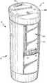
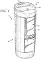
- FIG. 1is a front perspective view of one embodiment of an insulated drinking container
- FIG. 2is an exploded perspective view of one embodiment of an insulated drinking container
- FIG. 3is an exploded perspective view of one embodiment of a lid assembly for an insulated drinking container
- FIG. 4is an exploded perspective view of one embodiment of a plunger assembly for an insulated drinking container
- FIG. 5is a top plan view of the lid assembly of FIG. 3 ;
- FIG. 6is a bottom plan view of the lid assembly of FIG. 3 ;
- FIG. 7is a cross-sectional side view about line 7 - 7 of the insulated drinking container of FIG. 5 , with the sealing mechanism in the normal position;
- FIG. 8is a cross-sectional side view about line 8 - 8 of the insulated drinking container of FIG. 5 , with the sealing mechanism in the closed position;
- FIG. 9is an enlarged cross-sectional side view about line 7 - 7 of the insulated drinking container of FIG. 5 , with the sealing mechanism in the actuated position;
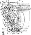
- FIG. 10is a cross-sectional perspective view of the sealing mechanism for an insulated drinking container in the normal position
- FIG. 11is a cross-sectional perspective view of the sealing mechanism for an insulated drinking container in the actuated position
- FIG. 12is a top perspective view of a sealing mechanism for an insulated drinking container with the lid cover partially broken away;
- FIG. 13is a front perspective view of another embodiment of a drinking container having a lid with a trigger actuated drinking orifice;
- FIG. 14is a side view of the lid of FIG. 13 ;
- FIG. 15is an exploded perspective view of the lid of FIG. 13 ;
- FIG. 16is an enlarged cross-sectional view of the lid about line 16 - 16 of FIG. 14 , when the trigger is in the normal position;
- FIG. 17is an enlarged cross-sectional view of the lid about line 16 - 16 of FIG. 14 , when the trigger is in the semi-actuated position;
- FIG. 18is an enlarged cross-sectional view of the lid about line 16 - 16 of FIG. 14 , when the trigger is in the fully actuated position.
- the container 10is generally comprised of a container body 12 for holding liquid, and a lid assembly 14 that can be secured to the container body 12 .
- the lid assembly 14generally covers an opening of the liquid receptacle 16 in the drinking container 10 .
- a seal assembly 18is provided and is preferably removably connected to the lid assembly 14 .
- a trigger assembly 20is utilized to actuate the seal assembly 18 to provide for opening and closing one or more openings for allowing liquid to be dispelled from the liquid receptacle 16 of the drinking container 10 .
- the trigger assembly 20is at least partially provided in a recess 22 in the container body 12 .
- the container body 12is formed of a dual-walled construction utilizing an inner wall component 24 and an outer wall component 26 , and having a cavity 28 therebetween.
- a dual-walled constructioncan be insulated with an insulating foam provided in the cavity 28 or with a vacuum sealed construction to increase the thermal efficiency of the container 10 .
- an insulating foamis inserted in the cavity 28 of the dual-walled container body 12 after the outer wall component 26 is connected to the inner wall component 24 .
- a vacuum seal insulation techniquemay be employed utilizing traditional vacuum seal techniques to vacuum seal the cavity 28 of the container body 12 .
- the inner wall component 24 and the outer wall component 26are made of stainless steel material.
- the inner wall component 24has a sidewall 30 joining a bottom wall 32 to define the liquid receptacle 16 of the container 10 .
- An opening 31 into the liquid receptacle 16is provided at the end of the sidewall 30 opposing the bottom wall 32 .
- the sidewall 30 of the inner wall component 24has a recess or depression 34 extending inwardly toward the liquid receptacle 16 ( FIG. 7 ).
- the recess or depression 34 in the sidewall 30 of the inner wall component 24 of the preferred embodimentis longitudinal in shape to accept the preferred trigger assembly 20 . Referring to FIGS. 7 and 8 , it is shown that, except for the depression 34 in the sidewall 30 , in one embodiment the sidewall 30 of the inner wall component 24 has a generally cylindrical shape.
- the outer wall component 26also has a recess or depression 36 generally corresponding to the depression 34 in the inner wall component 24 . It is understood that in such an embodiment it is not necessary that both the inner wall component 24 and outer wall component 26 have a depression 36 to create the recess 22 in the container body 12 , however, to allow for preferred nesting of the depressions 34 , 36 in the inner wall component 24 and outer wall component 26 , which in at least one embodiment results in minimizing the thickness of the cavity 28 between the inner wall component 24 and outer wall component 26 and maximizing the volume of the liquid receptacle 16 , such a configuration is preferred. As shown in FIGS. 2 and 7 , the depression 34 in the inner wall component 24 in the preferred embodiment is longitudinal in shape, however it does not extend the entire length of the sidewall 30 of the inner wall component 24 . Accordingly, the interior volume of the liquid receptacle 16 is maximized.
- the outer wall component 26is a generally cylindrical component, having a sidewall 38 and a hollow interior with openings at opposing ends of the sidewall. Further, in a preferred embodiment the outer wall component 26 has a cross-sectional geometry that changes from one end of the sidewall 38 to the opposing end of the sidewall 38 as the top portion of the outer wall component 26 has a flared aspect thereto.
- the outer wall component 26has a first opening 42 provided at one end of the sidewall 38 , and a second opening 44 provided at the other end of the sidewall 38 .
- the sidewall 38 of the outer wall component 26has a recess or depression 36 extending radially inwardly from a perimeter of the sidewall 38 toward the hollow interior thereof.
- the depression 36 in the outer wall component 26 of the preferred embodimentis longitudinal in shape to accept the preferred trigger assembly 20 .
- the depression 36 in the outer wall component 26also has a first portion 46 and a second portion 48 .
- the first portion 46 of the depression 36is that which corresponds to the recess 22 for retaining a portion of the trigger assembly 20
- the second portion 48corresponds to the recess for housing the body panel 50 .
- the first portion 46 of the depression 36is deeper than the second portion 48 of the depression 36 .
- the first portion 46 of the depression 36generally extends from the first opening 42 of the outer wall component 26 , however, the second portion 48 of the depression generally does not extend fully to the second opening 44 in the outer wall component 26 .
- the body panel 50serves a plurality of purposes, including providing a stop for the trigger assembly 20 , providing a filler to fill the second portion 48 of the outer depression 36 to decrease cost and increase the ease of manufacturability of the outer wall component 26 , and providing improved aesthetics for the container.
- the body panel 50is generally fixed to the outer wall component 26 via a panel weldment 52 (see FIG. 2 ) extending from the depression 36 in the outer wall component 26 . Because the body panel 50 is connected to the outer wall component 26 of the container 10 and within the longitudinal recess 22 thereof, the outer surface of the body panel 50 generally continues the generally cylindrical outer circumference of the lower portion of the container 10 .
- first and second circumferential rings 54 , 56are provided in the sidewall 30 adjacent the opening 31 to the liquid receptacle 16 (See FIGS. 7 and 8 ).
- the first circumferential ring 54is located proximal the opening 31 and extends generally radially outwardly and can be described as being formed as an outward annular deboss in the inner wall component 24 .
- the second circumferential ring 56is located adjacent the first circumferential ring 54 and distal the opening 31 with respect to the first circumferential ring 54 .
- the second circumferential ring 56extends generally radially inwardly and can be described as being formed as an inward annular emboss in the inner wall component 24 .
- the first and second circumferential rings 54 , 56are positioned immediately adjacent one another, and a portion of the second circumferential ring 56 is an inward extension of a lower leg 58 of the first circumferential ring 54 .
- the combination of the first and second circumferential rings 54 , 56 in the inner wall component 24assist in retaining the body insert 60 for securing the lid assembly 14 to the container body 12 . It is understood by those of ordinary skill in the art, however, that additional means for retaining the body insert to the container body are possible without departing from the scope or spirit of the present invention.
- the body insert 60generally comprises a component that is fixed, typically permanently, to the inner wall component 24 of the container body 12 to assist in seating the inner wall component 24 with respect to the outer wall component 26 , and to provide a connection point for securing the lid assembly 14 to the container body 12 .
- the body insert 60generally has an upper generally cylindrical portion 62 , a lower generally cylindrical portion 64 , and a flange 66 therebetween extending from a perimeter of the body insert 60 .
- the lower generally cylindrical portion 64has a shoulder 68 protruding radially outwardly from the generally cylindrical portion 64 .
- the shoulder 68is configured to mate with the first circumferential ring 54 in the inner wall component 24 of the container body 12 to assist in fixing the body insert 60 to the inner wall component 24 .
- the lower generally cylindrical portion 64 of the body insert 60is preferably pressed through the opening 31 in the inner wall component 24 and partially into the liquid receptacle 16 of the inner wall component 24 .
- the shoulder 68 on the lower generally cylindrical portion 64will generally snap into place in the first circumferential ring 54 .
- the second circumferential ring 56engages a lower portion of the shoulder 68 to operate as stop, thereby assisting in properly seating the body insert 60 and preventing the body insert 60 from being inserted too far into the liquid receptacle 16 .
- an upper leg 70 of the first circumferential ring 54engages an upper portion of the shoulder 68 to prevent the body insert 60 from being removed or disengaged from the inner wall component 24 .
- the body insert 60is preferably permanently fixed in place.
- a gasket 72is provided to assist in sealing the connection between the body insert 60 and the inner wall component 24 . As is described additionally herein, the gasket 72 also assists in sealing an exit to the cavity 28 between the inner and outer wall components 24 , 26 .
- the gasket 72has an outer geometry that generally mirrors the sidewall 38 configuration of the outer wall component 26 , including having a recess that matches the recess 36 in the outer wall component 26 .
- the gasket 72also has an aperture 74 through which the lower generally cylindrical portion 64 is fitted. The gasket 72 is generally positioned against the lower surface 78 of the flange 66 of the body insert 60 .
- a radially inward portion of the gasket 72is squeezed between the lower surface 78 of the flange 66 and the end of the sidewall 30 at the opening 31 of the inner wall component 24 to operate as a seal and prevent liquid from escaping between the body insert 60 and the inner wall component 24 .
- an outer portion of the gasket 72has a wiper seal 76 that engages the inner surface of the sidewall 38 of the outer wall component 26 .
- the outer portion of the gasket 72generally operates as a seal or barrier at one end of the cavity 28 between the inner wall component 24 and the outer wall component 26 .
- the flange 66extends from a perimeter of the body insert 60 between the upper generally cylindrical portion 62 and the lower generally cylindrical portion 64 .
- the flange 66has a first surface 78 that engages the gasket 72 between the body insert 60 and the inner wall component 24 , and a second surface 80 that engages the lip of the outer wall component 26 adjacent the first opening 42 of the outer wall component 26 , and is positioned between the container body 12 and the lid assembly 14 when the lid assembly 14 is fitted on the container body 12 .
- the second surface 80 of the flange 66has a plurality of steps 82 .
- One stepis the portion of the flange 66 that engages the lip of the outer wall component 26 , and other steps 82 assist in properly seating and retaining the gasket 72 , which has a corresponding step that mates with the steps 82 in the flange 66 .
- the flange 66has a perimeter that generally mirrors the perimeter of the lid assembly 14 of the container 10 . Accordingly, as shown in FIG. 2 , the flange 66 has a portion which extends above the recess 22 in the container body 12 . This portion of the flange 66 has an aperture 87 therethrough which allows a portion of the trigger assembly 20 to extend through the flange 66 and to mate with the transfer bar 160 in the lid assembly 14 . As shown in FIG. 2 , the flange 66 also has a pair of pivot retainers 89 depending from the lower surface 78 of the flange 66 on opposing sides of the aperture 87 in the flange 66 . As explained herein, the pivot retainers 89 engage ears 134 (see FIG. 2 ) extending from the trigger assembly 20 to allow the trigger assembly 20 to pivot thereabout for actuating the seal assembly 18 in the lid assembly 14 .
- the inner wall component 24can be fixed to the outer wall component 26 .
- a variety of components and/or fastenersare utilized, such as a wall nut 88 , a base 90 and a fastener 92 .
- the wall nut 88is fixed to the bottom wall 32 of the inner wall component 24 within a depression 94 at the outside of the bottom wall 32 .
- the base 90is a generally planar circular metal component having a plurality of apertures therein. In one embodiment, the base 90 is welded to a lip at the second opening 44 of the outer wall component 26 .
- the fastener 92such as a screw, is inserted through the middle aperture 100 in the base 90 and is threaded into the wall nut 88 .
- the outer wall component 26is pulled tighter against the inner wall component 24 until the second surface 80 of the flange 66 engages the lip of the outer wall component 26 .
- insulationis injected into the cavity 28 between the inner wall component 24 and the outer wall component 26 .
- the insulation foamis injected into the cavity 28 through one of the apertures, while the other aperture is used to allow air to escape from the cavity 28 .
- the bottom member 102 of the container body 12is connected to the outer wall component 26 .
- the bottom member 102has a cup-like configuration.
- the bottom member 102operates to conceal the base 90 and the affixing components that connect the inner and outer wall components 24 , 26 , as well as concealing the apertures in the base 90 .
- the sidewall 104 of the bottom member 102is secured, typically via ultrasonic welding, to the outer portion of the sidewall 38 of the outer wall component 26 to complete the container body 12 .
- an upper generally cylindrical portion 62is provided above the flange 66 and on the opposite side of the flange 66 as the lower generally cylindrical portion 64 identified above.
- the upper generally cylindrical portion 62has a first mating member 106 , which in a preferred embodiment is an internal thread 106 on the inner surface of the upper generally cylindrical portion 62 , that allows the body insert 60 to accept and retain the lid assembly 14 through the use of a corresponding mating member 190 , which is preferably a mating external thread, on a portion of the lid assembly 14 .
- the first mating member 106may be a bayonet-style mating member that is adapted to mate with the lid assembly 14 to secure the lid assembly 14 to the body insert 60 , or some other style mating member.
- the lid assembly 14is connected to the body insert 60 in only a single final position, thereby allowing various components of the trigger mechanism 20 to mate with various components of the sealing assembly 18 in the lid assembly 14 as is explained herein. In one embodiment, as shown in FIG.
- the upper generally cylindrical portion 62has a notch 108 which operates as a stop to ensure that the lid assembly 14 is not overtightened on the container body 12 and thus is properly seated on the body insert 60 such that the transfer bar 160 will appropriately engage the pusher lever 112 of the trigger assembly 20 .
- the body insert 60is generally made of a plastic material
- the body insert 60is made of a thermoplastic material which changes color as the liquid in the liquid receptacle 16 of the container 10 changes temperature. Accordingly, the user will be alerted as to the approximate temperature category of the liquid contents of the container 10 .
- the body insert 60is orange at room temperature, but changes to white as its temperature increases. In use the body insert 60 will change to white when the temperature of the liquid contents is approximately greater than 120° F. As the temperature of the liquid contents decreases the orange color of the body insert 60 will intensify until the body insert 60 becomes, as in one embodiment, an orange color.
- the body insert 60is an orange color it is an indication to the user that the temperature of the liquid contents is approximately 90° F. or less.
- the trigger assembly 20generally comprises a trigger member 110 and a pusher lever 112 .
- the trigger assembly 20generally resides in the recess 22 in the container body 12 .
- additional componentssuch as the trigger plate 114 , the body panel 50 and the body panel plate 118 are also provided therewith.
- the body panel plate 118is generally an aesthetic fixture mounted to the body panel 50
- the trigger plate 114is generally an aesthetic fixture mounted to the trigger member 110
- the body panel 50 and the trigger member 110are made of a plastic material, such as ABS
- the body panel plate 118 and the trigger plate 114are generally made of a textured fabric in a preferred embodiment, however, they may also be made of any acceptable material, including a stainless steel material.
- the body panel 50 with the body panel plate 118 connected theretois generally fixed in the second portion 48 of the recess 22 . More specifically, as shown in FIG.
- the body panel 50is connected in the recess 22 of the container body 12 at the top and bottom ends of the body panel 50 .
- a lip 53extends from the bottom of the body panel 50 , and the lip 53 is seated between the outer surface of the sidewall 38 of the outer wall component 26 in the second portion 48 of the depression 36 , and the inner surface of the sidewall 104 of the bottom member 102 . After the lip 53 is properly seated the top end of the body panel 50 can be secured to the container body 12 .
- the top end of the body panel 50is snapped against a connector 52 extending from the outer surface of the sidewall 38 of the outer wall component 26 in the second portion 48 of the depression 36 , and held in place by the connector 52 . Because the body panel 50 is connected to the outer wall component 26 of the container 10 and within the depression 36 thereof, the outer surface of the body panel 50 (i.e., the body panel plate 118 ) generally continues the generally cylindrical outer circumference of the lower portion of the container 10 .
- the trigger assembly 20can be connected to the container 10 . In one embodiment, however, a portion of the trigger assembly 20 is preassembled prior to connecting the trigger assembly 20 to the container 10 .
- the trigger plate 114is first fixed to the trigger member 110 .
- the trigger member 110is made of a plastic material, such as ABS, and the trigger plate 114 is made of stainless steel.
- the trigger member 110has a geometry that generally matches the geometry of the recess 22 of the container body 12 . Accordingly, in one embodiment the trigger member 110 is longitudinal in shape. In such a configuration the trigger member 110 has a first end 120 , a second end 122 , a first sidewall, 124 , a second sidewall 126 , an outer surface 128 (generally comprising the outer surface of the trigger plate 114 , if one is affixed thereto), an inner surface 130 , and a receiver 132 for connecting with the pusher lever 112 .
- the trigger member 110also a pair of ears 134 extending from the trigger member 110 adjacent the first end 120 thereof, and a stop 136 adjacent the second end 122 of the trigger member 110 .
- the ears 134 on the trigger member 110engage the respective pivot retainers 89 depending from the lower surface of the flange 66 to connect the trigger assembly 14 to the container 10 .
- the ears 134 on the trigger member 110have a cylindrically shaped portion which is inserted into a mating aperture in each respective pivot retainer 89 to fix the trigger assembly 20 to the body insert 60 , but also to allow the trigger member 110 to rotate about a pivot axis defined by a centerline through the pivot retainers 89 .
- the trigger member 110has a protrusion 135 extending from the outer surface 128 at the second end 122 of the trigger member 110 that operates as an indicator to indicate to the user where to push the trigger member 110 to actuate the sealing mechanism 18 on the container 10 for allowing liquid to be dispelled from the container 10 .
- the receiver 132 of the trigger member 110comprises a mating portion of the trigger member 110 into which a portion of the pusher lever 112 is inserted to mate the pusher lever 112 with the trigger member 110 .
- the receiver 132comprises an opening adjacent the inner surface 130 and extending through a portion of both the first and second sidewalls 124 , 126 of the trigger member 110 .
- pins 142 on the pusher lever 112are inserted into the receivers 132 to retain the pusher lever 112 to the trigger member 110 , but also to allow the pusher lever 112 to rotate with respect to the trigger member 110 .
- the pusher lever 112is connected to and pivots about the receiver 132 of the trigger member 110 at a position located generally a distance from the first end 120 of the trigger member 110 . In one embodiment the pusher lever 112 pivots about the trigger member 110 at a location approximately 1 ⁇ 4 of the length down from the first end 120 of the trigger 110 .
- the pusher lever 112comprises a body portion 140 , a plurality of pins 142 , a spring lever 144 , and an engaging member 146 .
- the spring lever 144extends from a lower side of the body portion 140 and is generally elongated in shape with a central portion 148 and an end 150 positioned distal both the body portion 140 and the pivot pins 142 extending from the body portion 140 . Accordingly, in this embodiment the spring lever 144 operates as a leaf spring.
- the engaging member 146 of the pusher lever 112generally extends from an opposing upper side of the body portion 140 .
- the engaging member 146has a detent area 152 that assists in engaging and retaining the transfer bar 160 for manipulating the sealing assembly 18 following actuation of the trigger member 110 .
- the pusher lever 112is connected to the trigger member 110 by inserting the pins 142 of the pusher lever 112 into the receiver 132 on the trigger member 110 . In this embodiment, however, the pusher lever 112 can still pivot about the axis of the pins 142 within the receiver 132 of the trigger member 110 . After the pusher lever 112 is connected to the trigger member 110 the trigger assembly 20 can be connected to the container body 12 .
- the stop 136 at the second end 122 of the trigger member 110is fitted in a recessed slot 154 on the top of the body panel 50 ; the engaging member 146 of the pusher lever 112 is fitted through the aperture 87 in the flange 66 of the body insert 60 ; and the ears 134 on the trigger member 110 are connected in a pivotal relationship within the pivot retainers 89 extending from a lower surface of the flange 66 of the body insert 60 . Accordingly, referring to FIG.
- FIG. 7illustrates one embodiment of the container 10 in the normal position wherein the sealing mechanism 18 is closed.
- FIGS. 9 and 11illustrate one embodiment of the container 10 in the actuated position whereby the sealing mechanism 18 is open.
- the trigger 110is pushed radially inward (generally at the protrusion 135 extending from the outer surface 128 at the second end 122 of the trigger member 110 ) toward the recess 22 .
- the second end 122 of the trigger 110pivots radially inward about its ears 124 in the pivot retainers 89 and toward the sidewall 38 of the outer wall component 26 , the inner surface 130 of the trigger member 110 pushes on the central portion 148 of the spring lever 144 .
- the pusher lever 112pivots about the axis of the pivot pins 142 thereby moving the engaging member 146 at the top of the pusher lever 112 radially outward in the aperture 87 of the flange 66 of the body insert 60 .
- the engaging member 146 of the pusher lever 112pivots away from the central axis of the container body 12 .
- the outer surface of the trigger 110is generally a continuum of the outer wall 38 of the cup body 12 . Further, the outer surface of the trigger 110 is generally coplanar with the outer wall 38 of the cup body 12 .
- first end 120 of the trigger 110may be pushed radially inward toward the longitudinal recess 22 to pivot the second end 122 of the trigger 110 outward from the container body 12 and to thereby provide a hook for sliding a strap, belt or some other member between the container body 12 and trigger 110 for retaining the container 10 thereto.
- a plurality of components provided in the lid assembly 14are utilized to interact between the trigger assembly 20 and the sealing assembly 18 .
- Such componentsare actuated by components of the trigger mechanism 20 and, in one embodiment, may include a transfer bar 160 , a pivot link 162 , and a pivot seal 164 .
- the transfer bar 160 and the pivot link 162are generally provided between the upper lid 166 and the lower lid 168 , and a majority of the pivot seal 164 is generally provided below the lower lid 168 .
- the lower lid 168is permanently fixed, such as by ultrasonic welding, to the upper lid 166 .
- the lower lid 168comprises a base member 170 having an upper surface 171 and a lower surface 173 , and a generally cylindrical extension 172 extending from the lower surface 173 .
- the base member 170has a plurality of apertures therein. For example, a first aperture 174 is provided to allow liquid to pass out of the liquid receptacle 16 and through the drink orifice 176 in the upper lid 166 .
- a second aperture 178is provided to allow the pivot link 162 to rotate against the pivot seal 164 to actuate the plunger 220 .
- a third aperture 180is provided as a vent opening to mate with the vent hole 182 in the upper lid 166 to allow built-up pressure to escape out of the drink receptacle 16 .
- a fourth aperture or recess 184is provided in the base member 170 to allow a portion of the transfer bar 160 to extend downward through the base member 170 to engage the trigger mechanism 20 .
- a series of apertures 186are provided to retain extensions 188 of the pivot seal 164 to connect the pivot seal 164 in place.
- the surface of the base member 170is polished around the first and third apertures 174 , 180 to assist in allowing excess liquid that is not expelled out through the respective openings in the upper lid 166 to drain more easily back into the liquid cavity 16 of the container 10 .
- the top surface of the upper lid 166 adjacent the drinking orifice and the vent holeare also preferably polished to allow excess liquid to drain more easily back into the drink receptacle 16 .
- the generally cylindrical extension 172 protruding downwardly from the lower surface 173 of the base member 170is utilized to mate the lid assembly 14 to the container body 12 .
- a mating member 190which in one embodiment is an external thread 190 on the outer surface of the cylindrical extension 172 , is adapted to mate with the first mating member 106 of the upper generally cylindrical portion 62 of the body insert 60 to join the lid assembly 14 to the container body 60 .
- the cylindrical extension 172has a first end that is adjacent and joined to the base member 170 , and a second end that extends away from and distal the base member 170 .
- the mating member 190is provided toward the first end of the cylindrical extension 172 . As shown in FIGS.
- a lid seal 192is joined to the second end of the cylindrical extension 172 about the outer circumference thereof to assist in sealing the lid assembly 14 to the container body 12 .
- the lower lid 168is made of a plastic material, such as an ABS material, and the lid seal 192 is made of silicon that is overmolded on the outer circumference of the cylindrical extension 172 . Referring to FIG. 9 , when the lid assembly 14 is fitted on the container body 12 , the lid seal 192 engages the interior surface of the body insert 60 to prevent liquid from escaping between the body insert 60 and the lower lid 168 .
- the transfer bar 160is generally L-shaped with a main body portion 194 generally resting on the upper surface 171 of the base member 170 of the lower lid 168 , and a transverse component 196 extending downward through a recess or aperture 184 in the base member 170 of the lower lid 168 .
- the transverse component 196has a mating surface 198 which is utilized to engage a mating surface 152 on the engaging member 146 of the pusher lever 112 .
- the main body portion 194 of the transfer bar 160generally comprises first and second opposing walls 200 , 202 with an opening 204 therebetween.
- a transverse portion 206joins the first and second opposing walls 200 , 202 .
- the transverse portion 206is also connected to the pivot link 162 to pivot or rotate the pivot link 162 that extends through the second aperture 178 in the base member 170 of the lower lid 168 and between the opposing walls 200 , 202 and against the pivot seal 164 to actuate a portion of the sealing assembly 18 .
- the transfer bar 160also has a pair of arms 208 which are connected to a shutter 210 to actuate the shutter 210 as described in more detail herein. Accordingly, the shutter 210 is mechanically connected to the trigger 110 .
- the pivot link 162has a shaft 212 portion at a first end of the pivot link 162 that connects in a receiver in the transverse portion 206 of the transfer bar 160 .
- the second end 216 of the pivot linkextends through the second aperture 178 in the lower lid 168 and contacts the upper surface 222 of the pivot seal 164 .
- the pivot link 162operates as a cam as the transfer bar 160 moves from its first or normal position (see FIGS. 7 and 10 ) to its second or actuated position (see FIGS. 9 and 11 ) to press on the pivot seal 164 and deform the pivot seal 164 downwardly against the plunger 220 of the seal assembly 18 .
- the pivot seal 164has an upper first surface 222 and a lower second surface 224 .
- a perimeter of the upper surface 222 of the pivot seal 164is connected, preferably in a fixed manner, to the lower surface 173 of the base member 170 of the lower lid 168 (see FIG. 11 ).
- a central portion of the pivot seal 164is resilient and can be deformed by the pivot link 162 . For example, when the trigger mechanism 20 is in the normal position the pivot link 162 merely rests on the upper surface 222 of the pivot seal 164 , but generally does not deform the pivot seal 164 (see FIGS. 7 and 10 ).
- the pivot link 162pushes downwardly on the upper surface 222 of the pivot seal 164 to deform the pivot seal 164 and press the lower surface 224 of the pivot seal 164 against the plunger 220 of the seal assembly 18 (see FIGS. 9 and 11 ).
- the shutter 210operates as a closing member for the drinking orifice 176 in the upper lid 166 . Because the shutter 210 is connected to the arms 208 of the transfer bar 160 , as the trigger assembly 20 is actuated the shutter 210 is opened and closed. In one embodiment the shutter 210 has a panel 226 connected to a pair of arms 228 . The shutter arms 228 are connected to the arms 208 of the transfer bar 160 . In the normal or closed position the shutter 210 closes the drinking orifice 176 (see FIG. 10 ), but as the transfer bar 160 is moved by the trigger mechanism 20 the shutter 210 rotates backwards to open the drinking orifice 176 in the upper lid 166 (see FIGS. 9 and 11 ).
- a gasket or sealis preferably provided at the connection surfaces between the drinking orifice 176 and the panel 226 of the shutter 210 .
- a silicon sealis overmolded on the upper surface of the panel 226 to seal the drinking orifice 176 when the shutter 210 is in the closed position, and in another embodiment a silicon seal is overmolded on the underside of the perimeter of the drinking orifice 176 to perform the same function.
- the transfer bar 160with pivot link 162 and shutter 210 connected thereto is placed in the appropriate location on the upper surface 171 of the base member 170 of the lower lid 168 prior to joining the upper lid 166 to the lower lid.
- the upper lid 168generally comprises a top drinking surface 230 , a sidewall 232 extending down from the drinking surface 230 , and a plurality of internal ribs 234 extending down from the underside of the top drinking surface 230 to define a plurality of chambers, including a drinking chamber 236 and a vent chamber 238 .
- the drink orifice 176extends through the top drinking surface 230 and provides access to the drinking chamber 236
- the vent hole 182extends through the top drinking surface 230 and provides access to the vent chamber 238 .
- a slight depression or well 240is provided in the top drinking surface 230 adjacent the drink orifice 176 to assist the flow of liquid to the user's mouth and to drain any remnant liquid back into the drinking chamber 236 for sealing by the shutter 210 .
- a slight depression or well 242is provided in the top drinking surface 230 adjacent the vent hole 182 .
- the upper lid 166is connected to the lower lid 168 , typically via ultrasonic welding, in strategic locations to properly direct the flow of liquid out of the liquid receptacle 16 and through the drinking hole 176 to the user, as well as directing gaseous pressure out of the liquid receptacle 16 and through the vent hole 182 .
- the upper surface 171 of the base member 170 of the lower lid 168is ultrasonically welded to the upper lid 166 at a shoulder in the sidewall and at various ribs 234 to ensure that liquid that flows out of the liquid receptacle 16 , when the sealing assembly 18 is actuated and the plunger 220 pushed down, through the first aperture 174 and into the drinking chamber 236 for dispelling through the drink orifice 176 in the upper lid 166 , without escaping elsewhere.
- the upper surface 171 of the base member 170 of the lower lid 168is ultrasonically welded to the upper lid 166 at the ribs 234 , which defines the sidewalls of the vent chamber 238 , to ensure that gas and/or liquid that is to vent out the vent hole 182 in the upper lid 166 , for example when the sealing assembly 18 is actuated and the plunger is pushed down, flows through the third aperture 180 in the lower lid 168 and into the vent chamber 238 for dispelling through the vent hole 182 in the upper lid 166 . Further, as shown in FIG.
- the third aperture 180 in the lower lid 168has a first cross-sectional area and first volume
- vent chamber 238has a second cross-sectional area and a second volume.
- the cross-sectional area and volume of the vent chamber 238being larger than that of the third aperture 180 .
- the size of the vent chamber 238is substantially larger than the size of the opening to the third aperture 180 such that as the sealing mechanism 18 is actuated and gas and/or liquid is released through the third aperture 180 in the lower lid 168 , the pressure is dissipated in the vent chamber 238 and is not transferred out through the vent hole 182 , which has generally the same area as the third aperture 180 . This is to prevent a chimney effect through the vent holes.
- the sealing assembly 18is shown in FIGS. 3, 4 and 6-12 .
- the sealing assembly 18is connected to the lid assembly 14 , and in one embodiment the sealing assembly 18 is removably connected to the lower lid 168 .
- at least a portion of the sealing assembly 18generally comprises a plunger 220 , a plunger gasket 250 , a spring 252 , a plunger retainer 254 and an end cap 256 .
- the shutter 210is also part of the sealing assembly 18 .
- the plunger 220is made of a plastic material
- the plunger gasket 250is a silicon component that operates as a seal and is connected to the plunger 220 .
- the plunger gasket 250is fixed to the plunger 210 to seal the plunger 220 against the lower surface 173 of the base member 170 of the lower lid 168 in the normal position of the trigger assembly 20 to simultaneously prevent liquid and/or gas from exiting the liquid receptacle 26 through any of the apertures 174 , 180 in the lower lid 168 . Accordingly, the seal operates as a valve for the container 10 .
- the plunger 220has an integral post 258 extending from a bottom of the plunger 220 .
- the post 258 of the plunger 220is utilized to connect the plunger 220 to the plunger retainer 254 with the spring 252 therebetween.
- the plunger retainer 254is a plastic component that has a plurality of spokes 260 and apertures 262 , and a main bore 264 through which the plunger post 258 is inserted.
- the spring 252is placed around the plunger post 258 , and the plunger post 258 is pushed downward into the main bore 264 of the plunger retainer 254 .
- the spring 252which is a preferably a stainless-steel compression spring in one embodiment, is positioned between the plunger 220 and the plunger retainer 254 to exert a separation force to push the plunger 220 away from the plunger retainer 254 .
- the sealing assembly 18is removably connected to the lid assembly 14 to allow the sealing assembly 18 to be removed for cleaning of the container 10 .
- the plunger retainer 254has external threads 261 on an outer surface of the sidewall 263 of the plunger retainer 254 .
- mating internal threads 265are provided on the inner surface of the cylindrical extension 172 of the lower lid 168 . The combination of these mating members 261 , 265 allow the sealing assembly 18 to be screwed to the mating threads on the underside of the lower lid 168 to secure the sealing assembly 18 in place (see FIG. 6 ), and subsequently unscrewed to be removed as a complete sub-assembly for cleaning.
- the plunger gasket 250In the closed or normal position, as shown in FIGS. 7, 8 and 10 , the plunger gasket 250 simultaneously closes both the first aperture 174 leading to the drinking chamber 236 and the drinking orifice 176 , as well as the third aperture 180 leading to the vent chamber 238 and the vent hole 182 .
- the plunger gasket 250in the actuated or open position the plunger gasket 250 simultaneously opens fluid flow through the first aperture 174 leading to the drinking chamber 236 and the drinking orifice 176 , as well as the third aperture 180 leading to the vent chamber 238 and the vent hole 182 .
- the trigger 110actuates the pusher lever 112 to move its engaging member 146 .
- the detent area 152 of the engaging member 146is engaged with a mating surface 198 of the transverse component 196 of the transfer bar 160 in the lid assembly 14 of the container 10 .
- the pusher lever 112moves radially outward the entire transfer bar 160 is moved horizontally away from the drinking aperture 176 of the container 10 .
- the pivot link 162 pivotally connected to the transverse portion 206 of the transfer bar 160pivots about the axis of its shaft portion 212 at its first end to allow its second end 216 to pivot or rotate downwardly through the second aperture 178 in the lower lid 168 and against the upper surface 218 of the pivot seal 164 .
- the central portion of the pivot seal 164is deformed downwardly by the force of the pivot link 162 to push the plunger 220 downwardly toward the plunger retainer 254 .
- liquidcan flow from the liquid receptacle 16 of the container body 12 , through the apertures 262 in the plunger retainer 254 and/or around the sidewall of the plunger retainer 254 , between the gap between the inner wall of the cylindrical extension of the lower lid 168 and the plunger 220 , and up through the fluid aperture 174 in the lower lid 168 .
- Vapor pressurecan take a similar path up through the vent holes 180 , 182 and vent chamber 238 .
- the horizontal motion of the transfer bar 160also changes the angular orientation of the shutter 210 positioned in the drinking chamber 236 of the lid assembly 14 and at the exit of the drinking aperture 176 in the top of the lid upper 166 of the lid assembly 14 .
- the shutter 210is pivotally connected to the arms 208 of the transfer bar 160 such that as the transfer bar 160 moves horizontally the shutter 210 rotates about its pivot connection to the open the drinking aperture 176 .
- the pusher lever 112engages the transfer bar 160 to move the transfer bar 160 horizontally away from the drinking aperture 176 , thereby providing pivotal movement to both the pivot link 162 and the shutter 210 .
- the pivotal movement of the pivot link 162causes the pivot link 162 to push the pivot seal 164 downwardly to engage the plunger 220 and move the plunger 220 downward to break the seal between the plunger gasket 250 and the lower surface 173 of the lid lower 168 .
- the shutter 210is simultaneously rotated to open the drinking aperture 176 .
- the liquidcan then pass through the fluid aperture 174 in the lid base 168 and out the drinking aperture 176 .
- FIGS. 6 and 7shows that the vertical axis of the entire plunger assembly 18 is offset from the vertical axis of the liquid receptacle 16 of the container body 12 .
- the userWhen the user is done drinking, the user releases the trigger 110 and the sealing assembly 14 , including the shutter 210 , automatically closes and moves to the normal position. Specifically, the spring force of the spring 252 is no longer overcome and the spring 252 forces the plunger 220 upwards against the bottom 173 of the lid base 168 to close the fluid aperture 174 and the vent aperture 180 . As this occurs, the pivot link 162 is rotated upward by the force of the spring 252 forcing the plunger 220 upward, thereby moving the transfer bar 110 to close the shutter 210 back to its normal, closed, non-actuated position.
- FIGS. 13-18Another embodiment of a drinking container 510 is shown in FIGS. 13-18 .
- the drinking container 510is generally comprised of a container body 512 having a cavity 516 for holding liquid, and a removable lid assembly 514 that can be secured to the container body 512 .
- the lid assembly 514generally covers an opening to the liquid receptacle 516 in the drinking container 10 .
- a seal assembly 518 and a trigger assembly 520are combined in the lid assembly 514 .
- the trigger assembly 520is utilized to operably actuate the seals of the seal assembly 518 to provide for opening and closing one or more openings for allowing liquid to be dispelled from the drinking opening 676 through the liquid receptacle 516 of the drinking container 510 , and also for allowing the internal pressure within the liquid receptacle 516 of the container body 512 to be released through the vent hole 682 in the upper lid 665 .
- the container body 512 of the drinking container 510may be an insulated container body 512 formed of a dual-walled construction as explained above, it may be an insulated container body formed of a different construction than described above, such as a single-walled construction, or it may be a non-insulated construction container body 512 . Additionally, the container body 512 generally has an opening 531 at the end of the sidewall 530 opposing the bottom wall of the container body 512 to provide access into the liquid receptacle 516 . The container body 512 generally has a longitudinal axis extending through the center of the container body 512 from the first end adjacent the opening to the second end adjacent the bottom wall of the container body 512 .
- an upper generally cylindrical portion of the container body 512has a first mating member 606 , which in a preferred embodiment is an internal thread 606 on the inner surface of the container body 512 generally adjacent the opening 531 to the liquid receptacle 516 of the container body 512 .
- the first mating member 606allows the container body 512 to accept and retain the lid assembly 514 through the use of a corresponding second mating member 690 , which is preferably a mating external thread, on a portion of the lid assembly 514 .
- the first mating member 606may be a bayonet-style mating member that is adapted to mate with the lid assembly 514 to secure the lid assembly 514 to the container body 512 , or any other style mating member that will assist in retaining the lid assembly 514 to the container body 512 .
- the lid assembly 514generally comprises an upper lid member 665 that is connected to a lower lid member 668 .
- Several gaskets or seals, such as upper lid gasket 667 and lower lid gasket 692are also a part of the lid assembly 514 .
- the seal assembly 518 , trigger assembly 520 , and other components utilized to actuate the seal assembly 518 between the normally closed and actuated positionsare provided in the lid assembly 514 .
- the lower lid member 668is permanently fixed, such as by ultrasonic welding, to the upper lid member 665 following the assembly of the appropriate components within the lid assembly 514 , including components of the seal assembly 518 and trigger mechanism 520 , as well as the other additional components utilized to actuate the seals of the seal assembly 518 .
- additional componentsinclude a shutter 710 , a first linkage member 800 , a second linkage member 802 and a spring 804 .
- the lower lid member 668comprises a generally cylindrical sidewall portion 672 , a substantially planar transverse flange member 670 that extends generally radially outwardly from a first or top end of the generally cylindrical sidewall portion 672 , and a central bridge member 675 spanning across the generally cylindrical sidewall portion 672 . Additionally, several supports, such as a pair of opposing upstanding gusset-type walls 677 , a first support member 679 and a second support member 681 extend upwardly from the central bridge member 675 .
- Various aperturesare also provided in the lower lid member 668 interior of the perimeter of the sidewall portion 672 to allow the liquid/gas/vapor to pass out of the liquid receptacle 516 and through either the drink orifice 676 in the upper lid 665 or through the vent aperture 682 in the upper lid 665 .
- the lower lid member 668 of the lid assembly 514also has a second mating member 690 , which in one embodiment is an external thread 690 , on the outer surface of the cylindrical sidewall portion 672 below the flange member 670 .
- the second mating member 690is adapted to mate with the first mating member 606 on the inner surface of the container body 512 adjacent the opening 531 to the liquid receptacle 516 of the container body 512 to removably join the lid assembly 514 with the container body 512 .
- the central bridge member 675generally extends across the opening in the generally cylindrical sidewall member 672 .
- the central bridge member 675provides additional structural support for the lower lid member 668 , as well as providing a base for supporting other members of the lower lid member 668 .
- the upstanding gusset-type walls 677 , the first support member 679 and the second support member 681extend upwardly from the central bridge member 675 .
- the upstanding gusset-type walls 677are provided to assist in supporting, preferably pivotally, various components within the lid assembly 514 .
- the upstanding gusset-type wallshave a first set of apertures 683 a for pivotally supporting the second linkage member 802 , and a second set of apertures 683 b for pivotally supporting the shutter 710 .
- the upstanding gusset-type wallsalso have an aperture 683 c for supporting one end of the spring member 804 for the shutter 710 .
- first support member 679 and second support member 681 of the lower lid member 668are generally utilized to mate with support members of the upper lid member 665 to provide overall rigidity to the lid assembly 514 , as well as to retain a portion of the trigger 610 in the appropriate location in the lid assembly.
- the lower lid gasket 692is provided against the lower surface of the substantially planar transverse flange member 670 that extends generally radially outwardly from the generally cylindrical sidewall portion 672 .
- the lower lid gasket 692is a form of an O-ring and thus the lower lid gasket 692 assists in sealing the lid assembly 514 to the container body 512 .
- the lower lid 668(preferably as well as the upper lid 665 ) is made of a plastic material, such as an ABS material, and the lower lid gasket 692 is made of silicon. Referring to FIGS. 15-18 , when the lid assembly 514 is fitted on the container body 512 , the lower lid gasket 692 engages the top of the sidewall 530 of the container body 512 to prevent liquid from escaping between the container body 512 and the lower lid 668 .
- the lower lid 668is fixedly connected to the upper lid 665 after the sealing assembly 518 , trigger assembly 520 and related components have been fixed in place within the lid assembly 514 .
- the upper lid 665generally comprises a top drinking surface 730 , a sidewall 732 extending down from the drinking surface 730 , and a plurality of internal ribs 734 extending down from the underside of the top drinking surface 730 which are utilized to provide structural stability and a connection point between the upper and lower lids 665 , 668 .
- the upper lid 665also has a drink orifice 676 that extends through the top drinking surface 730 and operably provides access to the liquid receptacle 516 of the container body 512 , as well as a vent aperture 682 that extends through the top drinking surface 730 and operably provides access to a vent chamber 738 of the drinking container 510 .
- the vent chamber 738is an enclosed chamber that is located beneath the vent aperture 682 and between the vent seal 683 and the vent aperture 682 .
- the vent chamber 738provides a chamber with an increased volume capacity to lower the pressure and volume of the vapor/gas as it is expelled past the vent seal 683 but before it exits through the vent aperture 682 .
- the vent chamber 738has a cross-sectional area greater than a cross-sectional area of the vent aperture 682 .
- the vent chamber 738has a first entrance aperture 739 at one end that provides an entrance to the vent chamber 738 from the liquid receptacle 516 of the container body 512 , a second exit aperture (the vent aperture 682 ), and a third access aperture 743 to provide access to the interior of the lid assembly 514 for the trigger 610 .
- the top drinking surface 730 of the upper lid 665has a slight depression or well 740 that slopes downwardly from the drinking orifice 676 to the vent aperture 682 .
- the well 740assists to drain any remnant liquid back into the liquid receptacle 516 through the vent aperture 682 .
- the top drinking surface 730also has a vent deflector plate 731 adjacent the vent aperture 682 .
- the deflector plate 731directs vapor being expelled out of the vent aperture 682 transverse to the longitudinal axis of the container body 512 and away from the user. Specifically, the vent deflector plate 731 prevents any vapor from being directed upwardly from the vent aperture 682 , and rather directs it sideways away from the user.
- the sidewall 732 of the upper lid 665extends down from the drinking surface 730 toward the container body 512 when the lid assembly 514 is connected to the container body 512 . As shown in FIGS. 14 and 15 , a majority of the sidewall 732 extends to a generally linear termination, however, a peninsular portion 733 of the sidewall 732 adjacent the trigger 610 extends downwardly therefrom. The peninsular portion 733 of the sidewall 732 has an aperture 735 therethrough. A shroud 737 and the trigger 610 of the trigger assembly 520 are seated within the aperture 735 in the sidewall 732 of the upper lid 665 .
- the upper lid 665is fixedly connected to the lower lid 668 at a variety of locations.
- the first support member 679 of the lower lid 668is connected to a rib 734 extending downwardly from the underside of the top drinking surface 730 of the upper lid 665 .
- the connection between the first support member 679 and the rib 734is provided around the trigger 610 as shown in FIGS. 16-18 .
- the second support member 681extend upwardly from the central bridge member 675 is connected to the lower portion of the vent chamber 738 .
- the transverse flange member 670 of the lower lid member 668is connected to an inner surface of the sidewall 732 of the upper lid 665 .
- a gasket 667is provided between the joint between the upper lid 665 and the lower lid 668 .
- an annular shoulder 739is provided on the interior surface of the sidewall 732 of the upper lid 665 .
- the geometry of the annular shoulder 739mates with the geometry of the substantially planar transverse flange member 670 that extends generally radially outwardly from the top end of the generally cylindrical sidewall portion 672 of the lower lid 668 .
- the gasket 667has a similar geometry to that of the annular shoulder 739 and transverse flange member 670 .
- the gasket 667is provided between the annular shoulder 739 of the upper lid 665 and the transverse flange member 670 of the lower lid 668 to assist in sealing the connection between the lower and upper lids 665 , 668 .
- the gasket 667operates as a seal to prevent liquid from escaping between the upper lid 665 and the lower lid 668 .
- the trigger 610 of the trigger assembly 520is connected to and transitions the first linkage member 800 , which operates to pivot the second linkage member 802 and ultimately pivot the shutter 710 to open and close the seal 726 to the drink opening 676 . Further, as is explained herein the trigger assembly 520 also operates to move the vent seal 683 away from the entrance aperture 739 to the vent chamber 738 to operably close and open access to the container cavity 516 through the vent aperture 682 , as well as a trigger seal 685 that seals the trigger 610 from the exterior of the lid assembly 514 .
- the trigger assembly 520generally comprises a trigger member 610 and a trigger spring 644 .
- the trigger 610is generally L-shaped with a main body portion 694 and a transverse portion 696 extending downwardly therefrom.
- the main body portion 694has a shaft-like shape.
- the trigger 610also has a pair of arms 708 at an end of the main body portion 694 that engages the first linkage member 800 to operably open and close the shutter 710 to alternately open and seal the drink orifice 676 .
- the main body portion 694 of the trigger 610extends through the access aperture 743 and into the vent chamber 738 of the lid assembly 514 .
- a portion of the main body portion 794 of the trigger 610is generally housed within the vent chamber 738 , and a portion of the main body portion 794 of the trigger 610 extends out of the vent chamber 738 , through the entrance aperture 739 to the vent chamber 738 , and into the cavity of the lid assembly 514 .
- the trigger 610also seats several seals, including the trigger seal 685 and the vent seal 683 . As shown in FIGS. 16-18 , the trigger seal 685 and the vent seal 683 are both seated on the main body portion 694 of the trigger 610 . Since the trigger 610 extends through the access aperture 743 and into the vent chamber 738 , the trigger seal 685 is required to seal this opening 743 once the trigger 610 is inserted into the lid assembly 514 . Specifically, in a preferred embodiment the interior of the vent chamber 738 has a cylindrical shape and thus the trigger seal 685 is a type of wiper O-ring that is seated in an arcuate recess 695 on the main body portion 694 of the trigger 610 .
- the trigger seal 685operates as a wiper seal contacting the interior surface of the vent chamber 738 to seal the area between the interior surface of the vent chamber 738 and the trigger 610 to prevent any liquid or vapor from escaping out of the vent chamber 738 through the access aperture 743 .
- the trigger seal 685is positioned on the trigger 610 between the vent aperture 682 and the access aperture 743 . In this manner the trigger seal 685 also operates as an end wall for the vent chamber 738 .
- the vent seal 683is also seated on the main body portion 694 of the trigger 610 . Like the trigger seal 685 the vent seal 683 is seated in another arcuate recess 697 on the main body portion 694 of the trigger 610 . This recess 697 , however, is positioned outside of the vent chamber 738 and adjacent the entrance aperture 739 to the vent chamber 738 . Accordingly, in this manner the vent seal 683 operates to seal the entrance 739 to the vent chamber 738 in a first normal position, as shown in FIG. 16 , and to open the entrance 739 to the vent chamber 738 in the both the intermediate actuated position of FIG. 17 and the second or fully actuated position of FIG. 18 .
- a shoulder 699is provided on the main body portion 694 of the trigger 610 adjacent the arcuate recess 697 for the vent seal 683 .
- the shoulder 699operates as a surface for the trigger spring 644 to exert a force on the trigger 610 .
- the trigger spring 644is a compression spring that has a first end contacting the combination of the first support member 679 of the lower lid 668 and the rib 734 of the upper lid 665 , and a second end contacting the shoulder 699 of the trigger 610 . Since the first end of the trigger spring 644 is fixed in place, the second end of the trigger spring 644 exerts a force on the trigger 610 in an attempt to maintain the trigger 610 in the normal or unactuated position (see FIGS.
- vent seal 683is pushed up against the outside of the vent chamber 738 at the entrance 739 thereto, effectively sealing the entrance 739 to the vent chamber 738 to preclude any liquid or vapor from being to escape out of the cavity 516 of the drinking container 510 .
- the transverse portion 696 of the trigger member 610is fixedly connected to and preferably integral with the main body portion 694 of the trigger member 610 .
- the transverse portion 696operates as a push-button actuator to actuate the trigger mechanism 520 and sealing mechanism 518 .
- the transverse portion 696 of the trigger member 610has a shape that generally matches the aperture 735 in the peninsular portion 733 of the sidewall 732 of the upper lid member 665 .
- the transverse portion 696is moveable from a first normal or non-actuated position shown in FIG. 16 , to a partially actuated position shown in FIG. 17 and a fully actuated position show in FIG. 18 . In the partially actuated position ( FIG.
- the vent seal 683is in the open position allowing vapor and internal pressure to be released through the entrance aperture 739 and to exit out the vent orifice 682 , but the shutter 710 is closed sealing the drinking orifice 676 .
- both the vent seal 683 and shutter 710are in the open position allowing liquid to be expelled out the drinking orifice 676 and allowing vapor and pressure to continue to be released from the vent opening 682 .
- the trigger mechanism 520can be actuated by exerting a generally radially inward force on the trigger member 610 to overcome the opposite force of the trigger spring 644 to push the trigger member 610 radially inward in the lid assembly 514 .
- the trigger 610is mechanically connected to the shutter 710 through the first and second linkage members 800 , 802 .
- the arms 708 at the end of the main body portion 694 of the trigger 610engage the first linkage member 800 to operably open and close the shutter 710 to seal the drink orifice 676 .
- the trigger 610is mechanically connected to the vent seal 683 .
- the first linkage member 800has a body portion 808 with a pair of outwardly extending arms 806 at one end of the body portion 808 and a slot 812 at an opposing end of the body portion 808 .
- the arms 806each have a tab 810 extending outwardly therefrom that rotatably engage the second linkage member 802 .
- the slot 812 in the opposing end of the body portion 808 of the first linkage member 800is designed to engage the arms 708 of the trigger 610 . Further, the slot 812 has an opening 814 to allow the arms 708 of the trigger 610 to be fitted within the slot 812 .
- the slot 812is sized such that when the trigger 610 is in both (a) the normal or non-actuated position (see FIG. 16 ), as well as (b) the partially actuated position (see FIG. 17 ), the shutter 710 and seal 726 on the shutter 710 are in the closed position preventing liquid from escaping through the drinking orifice 676 . In the partially actuated position, however, the vent seal 683 is open.
- the slot 812is also sized such that when the trigger 610 is in the fully actuated position (see FIG. 18 ), the shutter 710 and the seal 711 on the shutter 710 are in the open position to allow liquid to escape through the drinking orifice 676 . Accordingly, the slot 812 operates as a cam track for the arms 708 of the trigger 610 .
- the shape and size of the slot 812 in connection with the shape of the main body portion 694 of the trigger 610 and the stroke length of the trigger 610determine when the shutter 710 will be actuated.
- the actuation stroke of the trigger mechanism 520is defined as the movement of the trigger 610 a distance between the normal or closed position (see FIG. 16 ) and the fully actuated position (see FIG. 18 ).
- the arms 708 of the trigger 610are in a first position in the slot 812 of the first linkage member 800 , generally toward or touching one end wall 813 of the slot 812 .
- the second or partially actuated positionfrom 0 mm of travel to approximately 1 mm.
- the arms 708are positioned in the slot 812 between the first slot wall 813 and the second slot wall 815 .
- the arms 708In the actuated position (from approximately 1 mm. of travel to approximately 2 mm. of travel of the trigger 610 ) the arms 708 contact the second slot wall 815 and transition the first linkage member 800 to operably open the shutter 710 .
- the trigger 610does not transition the first linkage member 800 until the arms 708 of the trigger 610 engage the second wall 815 of the slot 812 .
- the vent seal 683opens first, and then the shutter 710 will open as described below during the second portion of the actuation stroke. This provides a built-in delay to allow the internal pressure and vapor to escape out of the vent opening and be dispersed by the vent shield rather than spurting out the drink orifice and at the user.
- the first linkage member 800is connected to the second linkage member 802 .
- the second linkage member 802has a body portion 820 with a first end and a second end.
- the first end of the second linkage member 802has a pair of apertures 821 to rotatably retain the tabs 806 of the first linkage member 800
- the second end of the second linkage member 802has a pair of inwardly extending tabs 822 that operably engage a cam track 824 on the shutter 710 .
- a roller member 826is provided on each tab 822 to allow the tabs 822 of the second linkage member 802 to engage the shutter 710 with less resistance.
- the tabs 822 with the roller members 826operate as cams within a cam track of the shutter 710 .
- a pair of outwardly extending pivot tabs 828extend from the body portion 820 of the second linkage member 802 , generally between the apertures 821 and the tabs 822 .
- the pivot tabs 828 of the second linkage member 812are fitted within the first set of apertures 683 a in the gusset walls 677 of the lower lid member 668 . Accordingly, the second linkage member 802 is able to rotate about the pivot tabs 828 when they are fitted in the first set of apertures 683 a.
- the arms 806 of the first linkage member 800are fitted within the apertures 821 of the second linkage member 802 .
- the arms 806are generally free to rotate within the apertures 821 of the second linkage member 802 .
- the trigger member 610actuates or moves laterally from the normal position to the actuated position
- the end of the first linkage member 800 having the slot 812moves somewhat laterally with the trigger member 610 .
- the first linkage member 800is also able to partially rotate about the arms 708 of the trigger 610 .
- the opposing end of the first linkage member 800 pivotally connected to the second linkage member 802is transitioned downwardly.
- This movementis controlled by the pivot connection of the second linkage member 802 with the gusset walls 677 of the lower lid member 668 .
- Due to the pivot connection between the pivot tabs 828 on the second linkage member 802 with the apertures 683 in the gusset walls 677the second linkage member 802 is restrained to pivoting about its pivot tabs 828 .
- the second linkage member 802generally pivots clockwise when moving from the normal position to the actuated position as shown in FIGS. 16-18 due to the force applied by the first linkage member 800 through the trigger 610 .
- the shutter 710is mechanically connected to the trigger 610 through the first and second linkage members 800 , 802 .
- the shutter 710operates as a closing member and seal for the drinking orifice 676 in the upper lid 665 .
- the shutter 710has a pair of shutter arms 728 , a pair of pivot members 729 , and a resilient seal 727 , preferably made of silicon or some other resilient material.
- the shutter arms 728have a slotted cam track 824 that retain the tabs 822 and roller members 826 of the second linkage member 802 .
- the pivot members 729 of the shutter 710are pivotally retained in the second set of apertures 683 b of the gusset walls 677 of the lower lid member 668 .
- the shutter 710is limited to pivoting (generally counter clockwise when transitioning from the normal to the actuated position, and clockwise when transitioning back to the normal position as shown in FIGS. 16-18 ) about its pivot members 729 in the apertures 683 b of the gusset wall 677 .
- the seal 727is positioned on the shutter 710 such that in the normal position the seal 727 of the shutter 710 fluidly closes the drinking opening 676 .
- Movement of the shutter 710is thus controlled by the trigger mechanism 520 .
- the trigger 610transitions the first linkage member 800 which in turn transitions the second linkage member 802 .
- the rollers 826 on the tabs 822 of the second linkage member 802pivot with the second linkage member 802 . Since the rollers 826 are positioned within the cam track 824 of the shutter arms 728 , the shutter 710 likewise pivots counter-clockwise about its pivot members 729 to change the angular orientation of the shutter 710 and accordingly open the drinking orifice 676 in the actuated position.
- the torsion spring 804has a first end positioned in one of the apertures 683 c on the gusset wall 677 , and a second end that engages the shutter 710 .
- the torsion spring 804exerts a force on the shutter 710 to retain the shutter 710 in the closed or normal position.
- a force and sufficient lateral translation movementare applied to the trigger 610 sufficient to overcome the spring force of the torsion spring 804 (as well as the spring force of the trigger spring) the shutter 710 will open.
- the shutter spring 804will exert a force to close the shutter 710 to seal the drinking opening 676 once the force on the trigger 610 is removed.
- a silicon sealis overmolded on the upper surface of the shutter 710 for sealing the drinking orifice 676 when the shutter 710 is in the closed position. Accordingly, the shutter 610 operates to operably close and open access to the container cavity through the drinking orifice 676 .
- the shutter 710 and the vent seal 683are normally in the closed position.
- the trigger 610operates to independently move the shutter 610 and the vent seal 683 from the closed or normal position to the open position following appropriate actuation of the trigger mechanism.
- the actuation of the trigger 610occurs in a two-part actuation stroke wherein the trigger 610 moves from its first position to its second position.
- the vent seal 683is transitioned from the normal or closed position to the actuated or open position to open access to the vent chamber 738 and the vent orifice 682 .
- the shutter 710remains closed.
- the shutter 710is transitioned from the normal or closed position to the actuated or open position to open the drinking orifice 676 . Further, the actuation occurs through lateral movement of the trigger 610 in a transverse direction to the longitudinal axis of the container body 512 .
- the userWhen the user is done drinking, the user releases the trigger 610 and the sealing assembly 514 , including the shutter 710 and the vent seal 683 , automatically close and return to the normal position due to the spring force of the trigger spring and the shutter spring.
Landscapes
- Engineering & Computer Science (AREA)
- Mechanical Engineering (AREA)
- Health & Medical Sciences (AREA)
- General Health & Medical Sciences (AREA)
- Pediatric Medicine (AREA)
- Closures For Containers (AREA)
Abstract
Description
Claims (20)
Priority Applications (1)
| Application Number | Priority Date | Filing Date | Title |
|---|---|---|---|
| US16/417,560US10993562B2 (en) | 2005-03-18 | 2019-05-20 | Travel container having drinking orifice and vent aperture |
Applications Claiming Priority (10)
| Application Number | Priority Date | Filing Date | Title |
|---|---|---|---|
| US66328005P | 2005-03-18 | 2005-03-18 | |
| US11/384,165US20060226160A1 (en) | 2005-03-18 | 2006-03-17 | Insulated drinking container |
| US11/698,797US7546933B2 (en) | 2005-03-18 | 2007-01-26 | Travel container having drinking orifice and vent aperture seals |
| US12/456,192US7997442B2 (en) | 2005-03-18 | 2009-06-12 | Travel container having drinking orifice and vent aperture |
| US13/206,121US8590731B2 (en) | 2005-03-18 | 2011-08-09 | Travel container having drinking orifice and vent aperture |
| US14/089,467US9095233B2 (en) | 2005-03-18 | 2013-11-25 | Travel container having drinking orifice and vent aperture |
| US14/815,850US9398823B2 (en) | 2005-03-18 | 2015-07-31 | Travel container having drinking orifice and vent aperture |
| US15/192,893US9808102B2 (en) | 2005-03-18 | 2016-06-24 | Travel container having drinking orifice and vent aperture |
| US15/805,029US10292513B2 (en) | 2005-03-18 | 2017-11-06 | Travel container having drinking orifice and vent aperture |
| US16/417,560US10993562B2 (en) | 2005-03-18 | 2019-05-20 | Travel container having drinking orifice and vent aperture |
Related Parent Applications (1)
| Application Number | Title | Priority Date | Filing Date |
|---|---|---|---|
| US15/805,029ContinuationUS10292513B2 (en) | 2005-03-18 | 2017-11-06 | Travel container having drinking orifice and vent aperture |
Publications (2)
| Publication Number | Publication Date |
|---|---|
| US20190335930A1 US20190335930A1 (en) | 2019-11-07 |
| US10993562B2true US10993562B2 (en) | 2021-05-04 |
Family
ID=46327126
Family Applications (8)
| Application Number | Title | Priority Date | Filing Date |
|---|---|---|---|
| US11/698,797ActiveUS7546933B2 (en) | 2005-03-18 | 2007-01-26 | Travel container having drinking orifice and vent aperture seals |
| US12/456,192ActiveUS7997442B2 (en) | 2005-03-18 | 2009-06-12 | Travel container having drinking orifice and vent aperture |
| US13/206,121Active2026-07-14US8590731B2 (en) | 2005-03-18 | 2011-08-09 | Travel container having drinking orifice and vent aperture |
| US14/089,467ActiveUS9095233B2 (en) | 2005-03-18 | 2013-11-25 | Travel container having drinking orifice and vent aperture |
| US14/815,850ActiveUS9398823B2 (en) | 2005-03-18 | 2015-07-31 | Travel container having drinking orifice and vent aperture |
| US15/192,893ActiveUS9808102B2 (en) | 2005-03-18 | 2016-06-24 | Travel container having drinking orifice and vent aperture |
| US15/805,029ActiveUS10292513B2 (en) | 2005-03-18 | 2017-11-06 | Travel container having drinking orifice and vent aperture |
| US16/417,560Active2026-05-23US10993562B2 (en) | 2005-03-18 | 2019-05-20 | Travel container having drinking orifice and vent aperture |
Family Applications Before (7)
| Application Number | Title | Priority Date | Filing Date |
|---|---|---|---|
| US11/698,797ActiveUS7546933B2 (en) | 2005-03-18 | 2007-01-26 | Travel container having drinking orifice and vent aperture seals |
| US12/456,192ActiveUS7997442B2 (en) | 2005-03-18 | 2009-06-12 | Travel container having drinking orifice and vent aperture |
| US13/206,121Active2026-07-14US8590731B2 (en) | 2005-03-18 | 2011-08-09 | Travel container having drinking orifice and vent aperture |
| US14/089,467ActiveUS9095233B2 (en) | 2005-03-18 | 2013-11-25 | Travel container having drinking orifice and vent aperture |
| US14/815,850ActiveUS9398823B2 (en) | 2005-03-18 | 2015-07-31 | Travel container having drinking orifice and vent aperture |
| US15/192,893ActiveUS9808102B2 (en) | 2005-03-18 | 2016-06-24 | Travel container having drinking orifice and vent aperture |
| US15/805,029ActiveUS10292513B2 (en) | 2005-03-18 | 2017-11-06 | Travel container having drinking orifice and vent aperture |
Country Status (1)
| Country | Link |
|---|---|
| US (8) | US7546933B2 (en) |
Families Citing this family (156)
| Publication number | Priority date | Publication date | Assignee | Title |
|---|---|---|---|---|
| US7546933B2 (en) | 2005-03-18 | 2009-06-16 | Ignite Usa, Llc | Travel container having drinking orifice and vent aperture seals |
| US20070187421A1 (en) | 2006-02-13 | 2007-08-16 | Espro Inc. | Method and apparatus for controlling fluid flow in a steaming pitcher |
| US20080272134A1 (en)* | 2007-05-03 | 2008-11-06 | Rohe Jeffrey T | Button actuated spill-proof lid for travel mug |
| US8272532B2 (en)* | 2007-12-21 | 2012-09-25 | Helen Of Troy Limited | Beverage container lid |
| US8342355B2 (en)* | 2008-02-12 | 2013-01-01 | Goade Ann M | Controlled flow drinking adapter and kit |
| USD581727S1 (en) | 2008-03-19 | 2008-12-02 | Ignite Usa, Llc | Drinking container lid |
| USD592456S1 (en)* | 2008-03-19 | 2009-05-19 | Ignite Usa, Llc | Drinking container |
| USD592905S1 (en) | 2008-04-07 | 2009-05-26 | Ignite Usa, Llc | Water bottle lid |
| USD592913S1 (en) | 2008-04-07 | 2009-05-26 | Ignote Usa, Llc | Water bottle |
| EP2288421B1 (en) | 2008-05-12 | 2019-03-13 | Espro Inc. | Apparatus for extracting an infusion |
| EP2238873A2 (en)* | 2009-02-12 | 2010-10-13 | Browne & Co | Travel mug |
| USD658006S1 (en)* | 2009-07-02 | 2012-04-24 | Huajun Yao | Drinking ware with multi-media module |
| US8215512B2 (en)* | 2009-08-14 | 2012-07-10 | Trudeau Corporation 1889 Inc. | Cap for a consumable liquid container |
| USD623473S1 (en)* | 2009-08-25 | 2010-09-14 | Dart Industries Inc. | Water bottle |
| US8348078B2 (en)* | 2010-02-12 | 2013-01-08 | Thermos L.L.C. | Leak proof drinking lid with pressure relief |
| US8919593B2 (en)* | 2010-07-16 | 2014-12-30 | Russell Sinacori | Lid and resiliently biased closure slider |
| US8403173B2 (en)* | 2010-07-30 | 2013-03-26 | Pacific Market International, Llc | Beverage container closure |
| US8550280B2 (en) | 2010-08-13 | 2013-10-08 | Paul R Steuer | Sealed container with integral button and orifice seal |
| USD656787S1 (en) | 2010-09-13 | 2012-04-03 | Ignite Usa, Llc | Beverage container |
| USD656360S1 (en) | 2010-09-13 | 2012-03-27 | Ignite Usa, Llc | Lid for beverage container |
| US9321064B2 (en)* | 2010-09-24 | 2016-04-26 | Blake Vanier | Drinking vessel with pump and methods |
| US8397940B2 (en)* | 2010-09-30 | 2013-03-19 | Zak Designs, Inc. | Fluid dispensing vessel |
| US8360258B2 (en) | 2010-11-15 | 2013-01-29 | Pacific Market International, Llc | Beverage container closure |
| US10421587B2 (en) | 2010-11-15 | 2019-09-24 | Pacific Market International, Llc | Beverage container closure |
| US8556113B2 (en)* | 2010-12-10 | 2013-10-15 | Dixie Consumer Products Llc | Lid adapter |
| US8464895B2 (en) | 2011-06-27 | 2013-06-18 | Pacific Market International, Llc | Beverage container with one-handed operation |
| USD667269S1 (en)* | 2011-09-02 | 2012-09-18 | Dart Industries Inc. | Drinking flask |
| US8573431B2 (en)* | 2011-09-07 | 2013-11-05 | Pacific Market International, Llc | Beverage container closure with venting |
| USD686448S1 (en)* | 2011-09-08 | 2013-07-23 | Thermos L.L.C. | Lid for a bottle |
| US8727176B2 (en) | 2011-09-13 | 2014-05-20 | Ignite Usa, Llc | Seal mechanism for beverage container |
| US8844762B2 (en) | 2011-11-15 | 2014-09-30 | Ignite Usa, Llc | Travel beverage container |
| US9908687B2 (en) | 2011-11-15 | 2018-03-06 | Ignite Usa, Llc | Travel beverage container |
| USD675873S1 (en) | 2011-11-16 | 2013-02-12 | Ignite Usa, Llc | Beverage container |
| US8978923B2 (en) | 2011-12-05 | 2015-03-17 | Pacific Market International, Llc | Beverage container closure with venting |
| US8907796B2 (en)* | 2012-03-08 | 2014-12-09 | Gws Tahoe Blue Llc | Valve and cap system for a beverage container |
| US20140238985A1 (en)* | 2013-02-27 | 2014-08-28 | Jerry Sweeney | Beverage container cap |
| US9320375B2 (en) | 2014-06-16 | 2016-04-26 | Iqhydr8, Llc | Activity and volume sensing beverage container cap system |
| US9327960B2 (en) | 2014-06-16 | 2016-05-03 | Iqhydr8, Llc | Volume sensing beverage container cap system |
| US9151605B1 (en) | 2014-06-16 | 2015-10-06 | Iqhydr8, Llc | Beverage container cap |
| USD700012S1 (en) | 2012-07-17 | 2014-02-25 | Ignite Usa, Llc | Lid for beverage container |
| USD699509S1 (en) | 2012-07-27 | 2014-02-18 | Ignite Usa, Llc | Lid for beverage container |
| USD693629S1 (en) | 2012-12-31 | 2013-11-19 | Ignite Usa, Llc | Beverage container |
| USD693630S1 (en) | 2012-12-31 | 2013-11-19 | Ignite Usa, Llc | Beverage container |
| US20140190966A1 (en)* | 2013-01-04 | 2014-07-10 | Antonio F. Coloneri | Container lid |
| CN104902789B (en) | 2013-01-11 | 2016-08-17 | 特洛伊海伦有限公司 | travel mug lid |
| US10238560B2 (en) | 2013-03-13 | 2019-03-26 | Hill-Rom Services, Inc. | Air fluidized therapy bed having pulmonary therapy |
| US9113698B2 (en) | 2013-03-15 | 2015-08-25 | Camelbak Products, Llc | Drink containers and cap assemblies |
| US20140284343A1 (en)* | 2013-03-25 | 2014-09-25 | WOW Plastics, LLC | Travel Mug Apparatus |
| US10501242B2 (en)* | 2013-03-27 | 2019-12-10 | Robert Licari | Oral motor development sipping spout |
| CN104138132B (en)* | 2013-05-08 | 2016-03-09 | 董永光 | Water tumbler |
| US9724629B2 (en) | 2013-05-20 | 2017-08-08 | Thermos L.L.C. | Bottle system and method for filtering or treating a beverage |
| USD725966S1 (en) | 2013-05-20 | 2015-04-07 | Thermos L.L.C. | Combined drink bottle and lid |
| USD719445S1 (en) | 2013-07-29 | 2014-12-16 | Camelbak Products, Llc | Beverage container cap closure |
| USD716657S1 (en) | 2013-07-29 | 2014-11-04 | Camelbak Products, Llc | Beverage container cap |
| CN105636874B (en) | 2013-09-03 | 2018-05-08 | 依格耐特美国有限公司 | Tourism container for drink with drop-down lid |
| USD742684S1 (en) | 2013-09-06 | 2015-11-10 | Ignite Usa, Llc | Lid for travel beverage container |
| USD729571S1 (en) | 2013-12-03 | 2015-05-19 | Scott Wilson Design, Ltd. | Internal filter for water bottle |
| US9555948B2 (en) | 2013-12-09 | 2017-01-31 | Rubbermaid Incorporated | Double-walled, vacuum-insulated container having inner coating cured at high temperature |
| USD732337S1 (en) | 2013-12-18 | 2015-06-23 | Ignite Usa, Llc | Lid for beverage container |
| CN105873833B (en)* | 2014-01-02 | 2018-04-03 | 利基斯托普有限公司 | Container lid and valve |
| EP3089630A4 (en)* | 2014-01-22 | 2018-07-04 | Ignite USA, LLC | Travel beverage container |
| USD748943S1 (en) | 2014-06-12 | 2016-02-09 | Ignite Usa, Llc | Lid for beverage container |
| JP6355447B2 (en)* | 2014-06-20 | 2018-07-11 | プラス株式会社 | Rotating mechanism and case body using the same |
| US9282838B2 (en) | 2014-07-01 | 2016-03-15 | Pacific Market International, Llc | Lockable beverage container closure |
| USD761624S1 (en) | 2014-08-05 | 2016-07-19 | Espro, Inc. | Infusing container |
| AU2015300836A1 (en) | 2014-08-07 | 2017-03-30 | Espro, Inc. | Press for extracting an infusion |
| USD769063S1 (en) | 2014-09-18 | 2016-10-18 | Iqhydr8, Llc | Beverage container cap with handle and integrated hole cover |
| USD741102S1 (en)* | 2014-10-09 | 2015-10-20 | Maverick Industries, Inc. | Portable warming device for hot beverage containers |
| CN104586188B (en)* | 2014-12-23 | 2016-04-27 | 吴海荣 | A kind of Vacuuming structure of metal vacuum thermos cup |
| US9706863B2 (en)* | 2014-12-31 | 2017-07-18 | Guangzhou Hekoumei Houseware Development Co., Ltd. | Thermo mug |
| USD774828S1 (en) | 2015-01-16 | 2016-12-27 | Ignite Usa, Llc | Beverage container |
| USD774827S1 (en) | 2015-01-16 | 2016-12-27 | Ignite Usa, Llc | Beverage container |
| USD773250S1 (en) | 2015-01-16 | 2016-12-06 | Ignite Usa, Llc | Beverage container |
| CA2922371A1 (en)* | 2015-03-06 | 2016-09-06 | Ignite Usa, Llc | Lid assembly for a container |
| USD792155S1 (en) | 2015-07-07 | 2017-07-18 | Ignite Usa, Llc | Beverage container |
| CA2935655C (en)* | 2015-07-17 | 2019-06-04 | Ignite Usa, Llc | Travel beverage container |
| USD795630S1 (en) | 2015-08-19 | 2017-08-29 | Bruce Constantine | Beverage press |
| USD796244S1 (en) | 2016-02-11 | 2017-09-05 | Espro, Inc. | Beverage press |
| US10112748B2 (en) | 2016-02-16 | 2018-10-30 | Jason Peters | One-handed operation bottle device |
| JP1558688S (en)* | 2016-02-18 | 2016-09-12 | ||
| CN105595740B (en)* | 2016-03-01 | 2017-08-22 | 方昱皓 | Cup lid for drinking cup link-type pushes closure bubbler |
| US10420433B2 (en) | 2016-03-03 | 2019-09-24 | Ignite Usa, Llc | No-spill drinking container |
| US10259620B2 (en)* | 2016-03-03 | 2019-04-16 | Ignite Usa, Llc | Lid assembly for a container |
| USD818768S1 (en) | 2016-03-03 | 2018-05-29 | Ignite Usa, Llc | Lid for beverage container |
| US20170253393A1 (en)* | 2016-03-04 | 2017-09-07 | Chef'n Corporation | Lever actuated lid and container and method for using same |
| CN105747765A (en)* | 2016-03-22 | 2016-07-13 | 汪贤荣 | Portable novel heat-insulating cup and using method thereof |
| CN105747766A (en)* | 2016-03-22 | 2016-07-13 | 义乌市格策日用品有限公司 | Vacuum cup convenient for pouring water and using method thereof |
| USD815901S1 (en) | 2016-05-04 | 2018-04-24 | Hardy Steinmann | Portable beverage container |
| USD821146S1 (en) | 2016-05-04 | 2018-06-26 | Hardy Steinmann | Portable beverage container |
| WO2017210554A1 (en)* | 2016-06-02 | 2017-12-07 | Herndon Jeffrey R | Container assembly and accessories therefor |
| USD813611S1 (en)* | 2016-06-28 | 2018-03-27 | Shenzhen Aivice Cup Industry Co., Ltd. | Automobile vacuum bottle |
| USD830126S1 (en) | 2016-08-03 | 2018-10-09 | Jeffrey T. Rohe | Travel mug |
| USD830127S1 (en) | 2016-09-07 | 2018-10-09 | Jeffrey T. Rohe | Travel mug |
| US20180118417A1 (en)* | 2016-10-31 | 2018-05-03 | Alfay Designs | Leak-Proof Push Button Lid |
| CA3043362C (en)* | 2016-11-08 | 2021-08-24 | AFJ Industries LLC | Container with automatic lid closure |
| USD849481S1 (en) | 2017-01-10 | 2019-05-28 | Ignite Usa, Llc | Beverage container |
| USD822429S1 (en) | 2017-01-10 | 2018-07-10 | Ignite Usa, Llc | Lid for beverage container |
| US10336513B2 (en) | 2017-02-24 | 2019-07-02 | Ignite Usa, Llc | Lid having a pre-venting lid lever and a seal arm assembly |
| USD830128S1 (en) | 2017-04-07 | 2018-10-09 | Retail Resource Group, LLC | Travel mug |
| WO2018222953A1 (en)* | 2017-06-02 | 2018-12-06 | The Curators Of The University Of Missouri | Lid with automatic open and close retention mechanism |
| US11172784B2 (en) | 2017-06-08 | 2021-11-16 | Leapfrog Product Development LLC | Dual removable end cap vessel |
| US10849445B2 (en) | 2018-05-01 | 2020-12-01 | Upslope Brands, Inc. | Beverage container |
| DE102018120136A1 (en)* | 2018-08-17 | 2020-02-20 | Rickard Nilsson | Pushing device for exerting a compressive force against goods of a goods presentation device, shelf unit and goods presentation device |
| US11396407B2 (en)* | 2018-11-09 | 2022-07-26 | Igloo Products Corp. | Container lid with push button and linearly translating locking mechanism |
| US10829275B2 (en)* | 2018-12-03 | 2020-11-10 | Jaxamo Ltd | Fitness bottle |
| USD931681S1 (en) | 2019-02-01 | 2021-09-28 | Leapfrog Product Development LLC | Beverage container |
| USD929182S1 (en) | 2019-02-01 | 2021-08-31 | Leapfrog Product Development LLC | Water bottle |
| USD921422S1 (en) | 2019-02-22 | 2021-06-08 | Leapfrog Product Development LLC | Beverage container lid |
| USD910368S1 (en) | 2019-02-22 | 2021-02-16 | Leapfrog Product Development LLC | Beverage container lid |
| USD965388S1 (en) | 2019-02-22 | 2022-10-04 | Leapfrog Product Development LLC | Beverage container |
| USD906055S1 (en) | 2019-02-27 | 2020-12-29 | Leapfrog Product Development LLC | Beverage container |
| USD925287S1 (en) | 2019-03-06 | 2021-07-20 | Leapfrog Product Development LLC | Beverage container |
| USD925985S1 (en) | 2019-03-07 | 2021-07-27 | Leapfrog Product Development LLC | Beverage container |
| USD928556S1 (en) | 2019-03-07 | 2021-08-24 | Leapfrog Product Development LLC | Beverage container lid |
| USD925972S1 (en) | 2019-03-11 | 2021-07-27 | Leapfrog Product Development LLC | Beverage container lid |
| USD982965S1 (en) | 2019-03-22 | 2023-04-11 | Leapfrog Product Development LLC | Beverage container lid |
| USD924623S1 (en) | 2019-03-22 | 2021-07-13 | Leapfrog Product Development LLC | Beverage container lid |
| USD902647S1 (en) | 2019-03-22 | 2020-11-24 | Leapfrog Product Development LLC | Beverage container lid |
| USD903406S1 (en) | 2019-03-22 | 2020-12-01 | Leapfrog Product Development LLC | Beverage container lid |
| USD901250S1 (en) | 2019-05-29 | 2020-11-10 | Leapfrog Product Development LLC | Beverage container |
| USD897157S1 (en) | 2019-05-29 | 2020-09-29 | Leapfrog Product Development LLC | Beverage container |
| USD913035S1 (en) | 2019-05-29 | 2021-03-16 | Leapfrog Product Development LLC | Beverage container lid |
| USD897159S1 (en) | 2019-05-29 | 2020-09-29 | Leapfrog Product Development LLC | Beverage container |
| USD903407S1 (en) | 2019-05-29 | 2020-12-01 | Leapfrog Products Development LLC | Beverage container lid |
| USD984213S1 (en) | 2019-05-29 | 2023-04-25 | Leapfrog Product Development LLC | Beverage container |
| USD911769S1 (en) | 2019-05-29 | 2021-03-02 | Leapfrog Product Development LLC | Beverage container lid |
| USD897158S1 (en) | 2019-05-29 | 2020-09-29 | Leapfrog Product Development LLC | Beverage container |
| USD938777S1 (en) | 2019-05-29 | 2021-12-21 | Leapfrog Product Development LLC | Beverage container lid |
| US11077995B2 (en) | 2019-06-12 | 2021-08-03 | Leapfrog Product Development LLC | Slider lid for beverage container |
| US11066217B2 (en) | 2019-06-14 | 2021-07-20 | Leapfrog Product Development LLC | Twist lid for beverage container |
| US11511917B2 (en)* | 2019-09-13 | 2022-11-29 | Peter C. Wierzbicki | Drinking spout with trigger and valve mechanism for commercial bottles and cans |
| USD907960S1 (en) | 2019-09-18 | 2021-01-19 | Leapfrog Product Development LLC | Beverage container |
| USD908430S1 (en) | 2019-09-18 | 2021-01-26 | Leapfrog Product Development LLC | Beverage container |
| USD901979S1 (en) | 2019-09-18 | 2020-11-17 | Leapfrog Product Development LLC | Beverage container |
| US11628983B2 (en) | 2019-09-20 | 2023-04-18 | Leapfrog Product Development LLC | Soft chug lid for beverage container |
| US11510512B2 (en) | 2019-09-20 | 2022-11-29 | Leapfrog Product Development LLC | Soft straw lid for beverage container |
| USD923411S1 (en) | 2019-11-05 | 2021-06-29 | Leapfrog Product Development LLC | Beverage container |
| USD923412S1 (en) | 2019-11-05 | 2021-06-29 | Leapfrog Product Development LLC | Beverage container |
| WO2021091826A1 (en)* | 2019-11-05 | 2021-05-14 | Runway Blue, Llc | Lid for a drinking vessel with integrated venting mechanism |
| US11835368B2 (en) | 2019-11-06 | 2023-12-05 | Stephanie Lawson | Spill resistant beverage container assembly |
| US11577890B2 (en) | 2020-04-09 | 2023-02-14 | LWD-BB Inc. | Beverage container |
| WO2021225718A1 (en)* | 2020-05-07 | 2021-11-11 | Richmond Derek | Container or vessel having an anti-splash device and an anti-splash device for a container or a vessel |
| AU2021327752A1 (en) | 2020-08-20 | 2023-04-06 | Runway Blue, Llc | Drinking vessel lid with magnetic sealing mechanism |
| CN112890571B (en)* | 2021-02-05 | 2021-12-17 | 长沙理工大学 | A self-heating hot pot with anti-scald structure |
| US11136171B1 (en)* | 2021-03-08 | 2021-10-05 | Highwave | Lid |
| US11628985B2 (en)* | 2021-03-08 | 2023-04-18 | Gary Ross | Lid |
| CN215838249U (en)* | 2021-07-02 | 2022-02-18 | 广州合口美家居用品开发有限公司 | Bowl cover and thermos cup that lock was joined in marriage to button |
| CN113679229B (en)* | 2021-09-29 | 2025-04-22 | 深圳市中旻科技有限公司 | A push-type cup cover |
| TWD222975S (en)* | 2021-10-18 | 2023-01-01 | 新加坡商飛騰新加坡私人有限公司 | Drinking lid |
| US20230159257A1 (en)* | 2021-11-19 | 2023-05-25 | Crunch Tech, Inc. | Cup system for simultaneous delivery of contents from separated cups to a mouth of a user |
| US12043459B2 (en)* | 2022-03-25 | 2024-07-23 | Base Brands, Llc | Drinking vessel with lid and locking cover |
| USD1032298S1 (en) | 2022-06-09 | 2024-06-25 | Thompson Mug Company Llc | Drink container |
| USD1068386S1 (en) | 2022-06-09 | 2025-04-01 | Thompson Mug Company Llc | Drink container |
| USD1039336S1 (en) | 2022-08-23 | 2024-08-20 | Leapfrog Product Development LLC | Beverage container |
| USD1045509S1 (en) | 2022-08-23 | 2024-10-08 | Leapfrog Product Development LLC | Beverage container |
| US20240294308A1 (en)* | 2023-03-03 | 2024-09-05 | Brumis Imports Inc. | Container lid |
Citations (176)
| Publication number | Priority date | Publication date | Assignee | Title |
|---|---|---|---|---|
| US830142A (en) | 1906-03-27 | 1906-09-04 | William Ebbing | Condiment-holder. |
| US1072588A (en) | 1912-08-14 | 1913-09-09 | William T Duncan | Milk-can container and milk-server. |
| US2193232A (en) | 1939-05-17 | 1940-03-12 | Na Mac Products Corp | Liquid dispensing device |
| US2447870A (en) | 1944-07-01 | 1948-08-24 | Bernard H Polcyn | Drinking container and jar closure fitting |
| US2622420A (en) | 1949-07-07 | 1952-12-23 | William W Rice | Drinking cup |
| US2799437A (en) | 1954-10-18 | 1957-07-16 | Jepson Percy | Separator for use in separating liquids of different specific gravity |
| US3059816A (en) | 1957-02-19 | 1962-10-23 | Schenley Ind Inc | Combination container closure and pouring device |
| US3635380A (en) | 1970-01-05 | 1972-01-18 | Nospil Ltd | Container closure |
| US3739938A (en) | 1971-05-20 | 1973-06-19 | N Paz | Non-spill cup |
| US3964631A (en) | 1974-06-24 | 1976-06-22 | Albert Kenneth J | Drinking receptacle |
| US3967748A (en) | 1975-06-03 | 1976-07-06 | Thermo Seal | Drinking receptacle valve means |
| US3972443A (en) | 1974-11-01 | 1976-08-03 | Thermo Seal | Drinking receptacle |
| US4094433A (en) | 1977-01-14 | 1978-06-13 | Thermo-Seal, Inc. | Drinking receptacle valve means |
| US4099642A (en) | 1977-12-01 | 1978-07-11 | Dart Industries, Inc. | Drinking receptacle cover and valve assembly |
| US4133446A (en) | 1978-02-27 | 1979-01-09 | Thermo-Seal, Inc. | Drinking vessel cover with valve controlled openings |
| US4136799A (en) | 1977-09-26 | 1979-01-30 | Inventor's Inc. | Decanter |
| US4171060A (en) | 1978-12-11 | 1979-10-16 | Spil-Les | Covered drinking cup |
| US4212408A (en) | 1978-11-03 | 1980-07-15 | Orion Industries, Inc. | Beverage drinking container |
| US4276992A (en) | 1979-03-05 | 1981-07-07 | Susich Roland J | Drinking cup with laterally actuated valve |
| US4303173A (en) | 1979-07-02 | 1981-12-01 | Dart Industries Inc. | Mug type drinking receptacle with cover and valve |
| USD288667S (en) | 1984-07-11 | 1987-03-10 | Miner Container Printing, Inc. | Container closure |
| US4686725A (en) | 1985-10-28 | 1987-08-18 | Span America Medical Systems | Mattress cushion with securement feature |
| US4706313A (en) | 1986-05-01 | 1987-11-17 | Comfortex, Inc. | Decubitus ulcer mattress |
| US4711372A (en) | 1987-02-02 | 1987-12-08 | Sunbeam Plastics Corporation | Tamper indicating closure |
| US4712704A (en) | 1987-02-19 | 1987-12-15 | Ramsey Douglas P | Self-sealing closure |
| US4779766A (en) | 1987-02-13 | 1988-10-25 | Seaquist Closures | Dispensing closure for a container |
| US4801053A (en) | 1986-12-22 | 1989-01-31 | Kaster Eugene J | Valved dispensing spout |
| US4881668A (en) | 1988-06-08 | 1989-11-21 | Seaquist Closures, A Division Of Pittway Corporation | Closure with open lid retainer |
| US4901387A (en) | 1988-03-21 | 1990-02-20 | Luke John K | Mattress overlay with individual foam springs |
| USD315872S (en) | 1988-11-14 | 1991-04-02 | CinTom, Inc. | Closure for a beverage can |
| US5025519A (en) | 1986-10-22 | 1991-06-25 | Span-America Medical Systems, Inc. | Multi-section mattress overlay for systematized pressure dispersion |
| US5039158A (en) | 1990-03-15 | 1991-08-13 | Edmund Maier | Seating cushion |
| US5070560A (en) | 1990-10-22 | 1991-12-10 | Healthflex, Inc. | Pressure relief support system for a mattress |
| US5082134A (en) | 1990-11-28 | 1992-01-21 | Ramsey Douglas P | Self-sealing closure |
| US5118014A (en) | 1990-11-05 | 1992-06-02 | Bomatic, Inc. | Spill-proof mug |
| US5153977A (en) | 1991-02-01 | 1992-10-13 | Nippon Sanso Corporation | Method for making double-walled insulating metal container |
| US5163196A (en) | 1990-11-01 | 1992-11-17 | Roho, Inc. | Zoned cellular cushion with flexible flaps containing inflating manifold |
| US5169016A (en) | 1992-02-20 | 1992-12-08 | Hinz Jr Gunter | Method and apparatus for selectively sealing and pouring liquid from a container |
| US5179742A (en) | 1991-11-01 | 1993-01-19 | Stryker Corporation | Pressure reduction mattress |
| US5199597A (en) | 1991-08-30 | 1993-04-06 | Gladish William C | Self-closing container lid |
| US5222623A (en) | 1991-08-15 | 1993-06-29 | Douglas R. Eger | Covered drinking vessel |
| US5244113A (en) | 1992-08-24 | 1993-09-14 | Northwestern Bottle Company | Container lid assembly |
| US5249703A (en) | 1993-03-26 | 1993-10-05 | Morry Karp | Travel mug |
| US5307950A (en) | 1990-10-02 | 1994-05-03 | Hongbiao Li | Container for liquids |
| USD355322S (en) | 1993-12-03 | 1995-02-14 | Span-America Medical Systems, Inc. | Tri-zone mattress overlay |
| US5427271A (en) | 1994-06-06 | 1995-06-27 | Wang; Paul S. | Canteen with a spring biased valve actuated by a push button |
| US5462185A (en) | 1994-07-18 | 1995-10-31 | Walker, Iii; Clifford M. | Dispensing closure for fluid containers |
| US5461741A (en) | 1992-02-20 | 1995-10-31 | Graebe; Robert H. | Modular cushion construction with foamed base |
| US5465866A (en) | 1994-07-11 | 1995-11-14 | Belcastro; Domenic | Automatically sealing cup |
| US5477980A (en) | 1994-12-08 | 1995-12-26 | Chaffin; Jeffrey D. | Receptacle cover with valve controlled openings |
| US5485938A (en) | 1995-03-24 | 1996-01-23 | Boersma; Drew H. | Cup lid assembly |
| USD367611S (en) | 1995-03-01 | 1996-03-05 | George J. Wagner, III | Dispensing cap |
| USD373927S (en) | 1995-02-17 | 1996-09-24 | Kramer Jeffrey A | Lid |
| US5570797A (en) | 1995-03-06 | 1996-11-05 | Yeh; Frank | Mug and multipurpose lid combination |
| US5573139A (en) | 1995-07-05 | 1996-11-12 | Yeh; Frank | Drinking mug with lid and mug body formed from one piece |
| US5586346A (en) | 1994-02-15 | 1996-12-24 | Support Systems, International | Method and apparatus for supporting and for supplying therapy to a patient |
| US5596781A (en) | 1992-02-20 | 1997-01-28 | Crown Therapeutics, Inc. | Vacuum/heat formed cushion with pyramidal, inflatable cells |
| US5606754A (en) | 1989-03-09 | 1997-03-04 | Ssi Medical Services, Inc. | Vibratory patient support system |
| US5630238A (en) | 1995-08-04 | 1997-05-20 | Hill-Rom, Inc. | Bed with a plurality of air therapy devices, having control modules and an electrical communication network |
| US5649331A (en) | 1994-06-03 | 1997-07-22 | Span-America Medical Systems, Inc. | Self-adjusting pressure relief support system and methodology |
| US5666681A (en) | 1995-01-03 | 1997-09-16 | Hill-Rom, Inc. | Heel pressure management apparatus and method |
| US5680951A (en) | 1995-08-07 | 1997-10-28 | Feltman, Iii; Charles H. | Flow control cover for a cup |
| US5689845A (en) | 1996-04-17 | 1997-11-25 | Roho, Inc. | Expansible air cell cushion |
| USD386948S (en) | 1996-10-09 | 1997-12-02 | The Thermos Company | Travel mug |
| US5711452A (en) | 1994-12-08 | 1998-01-27 | Chaffin; Jeffrey D. | Valve controlled receptacle cover |
| US5753289A (en) | 1995-03-10 | 1998-05-19 | Ness; Richard B. | Portable food container and method for storing and dispensing dry and liquid food |
| USD394778S (en) | 1996-02-12 | 1998-06-02 | PTS Askeroth AB | Kitchen utensil for hot and cold liquids |
| USD397905S (en) | 1997-10-23 | 1998-09-08 | Asdak International | Thermos bottle-cup for use in motor vehicles |
| US5845352A (en) | 1996-07-12 | 1998-12-08 | Roho, Inc. | Foam-air hybrid cushion and method of making same |
| USD404613S (en) | 1997-04-21 | 1999-01-26 | Nippon Sanso Corporation | Cup with lid |
| USD406006S (en) | 1997-04-21 | 1999-02-23 | Nippon Sanso Corporation | Lid for a container |
| USD408221S (en) | 1994-12-07 | 1999-04-20 | Heineken Technical Services, B.V. | Beverage container |
| US5987668A (en) | 1997-09-15 | 1999-11-23 | Span-America Medical Systems, Inc. | Fabric covered mattress pad |
| USD416755S (en) | 1998-08-06 | 1999-11-23 | Punch Products Usa | Mug lid design with pivotal closure |
| USD417360S (en) | 1998-11-10 | 1999-12-07 | Crown Products | Cup lid |
| US6010029A (en) | 1998-11-27 | 2000-01-04 | Wang; Jung-Liang | Container lid assembly |
| US6053474A (en) | 1998-09-16 | 2000-04-25 | Corning Consumer Products Company | Vent valve |
| US6098834A (en) | 1997-06-11 | 2000-08-08 | Nippon Sanso Corporation | Cap for beverage container |
| US6102244A (en) | 1999-10-20 | 2000-08-15 | The Thermos Company | Mug with multiple sip holes and lid gasket |
| US6116476A (en) | 2000-02-04 | 2000-09-12 | Huang; Frank Teh-Hsiung | Push-button type bottle head |
| US6119291A (en) | 1995-08-04 | 2000-09-19 | Hill-Rom, Inc. | Percussion and vibration therapy apparatus |
| US6126035A (en) | 1999-10-21 | 2000-10-03 | Packaging Resources Incorporated | Plastic beverage cup with integral handle and method of forming plastic beverage cup with integral handle |
| US6158608A (en) | 1996-09-18 | 2000-12-12 | Cetoni Umwelttechnologie Entwicklungsgesellschaft Mbh | Container, in particular a drinks can, and lid for such a container |
| USRE37016E1 (en) | 1995-07-17 | 2001-01-16 | Playtex Products, Inc. | Flow control element and covered drinking cup |
| USD437229S1 (en) | 1999-02-13 | 2001-02-06 | Crown Cork & Seal Technologies Corporation | Container |
| US6223369B1 (en) | 1997-11-14 | 2001-05-01 | Span-America Medical Systems, Inc. | Patient support surfaces |
| US6276560B1 (en) | 2000-08-22 | 2001-08-21 | Niko Products, Inc. | Automatically sealing cup |
| USD447693S1 (en) | 2000-02-09 | 2001-09-11 | Nestec, S.A. | Container |
| US6324709B1 (en) | 1998-07-31 | 2001-12-04 | France Bed Co., Ltd. | Mattress apparatus and bed apparatus |
| US6352166B1 (en) | 1999-02-10 | 2002-03-05 | William Industries, Inc. | Self-closing lid apparatus |
| US6401990B1 (en) | 2000-06-19 | 2002-06-11 | Seaquist Closures Foreign, Inc. | Finger-operable pump actuator with finger pad |
| USD460894S1 (en) | 2000-11-07 | 2002-07-30 | Pepsi Lipton Tea Partnership | Glass |
| US6443325B1 (en) | 1999-10-21 | 2002-09-03 | Huhtamaki Holding, Inc. | Plastic cup with integral handle and method of forming plastic cup with integral handle |
| US6471085B1 (en) | 1999-10-04 | 2002-10-29 | Anthony J. Gallo | Temperature cup |
| USD470009S1 (en) | 2002-03-04 | 2003-02-11 | Punch Products Usa, Inc. | Beverage container lid |
| USD471808S1 (en) | 2001-03-15 | 2003-03-18 | De Castro Couto Gilberto | Spout for beverage can |
| US20030071041A1 (en) | 1997-10-28 | 2003-04-17 | Gateway Plastics Incorporated | Closure for a container |
| US6557717B1 (en) | 2001-12-12 | 2003-05-06 | David Keck | Non-spill beverage container |
| US6623080B2 (en) | 2001-08-09 | 2003-09-23 | Roho, Inc. | Cellular cushion vehicle seat system |
| US6644490B2 (en) | 2001-05-17 | 2003-11-11 | Solo Cup Company | Lid |
| US6679397B2 (en) | 2001-08-06 | 2004-01-20 | Solo Cup Company | Container lid with closure member |
| US6701556B2 (en) | 1998-05-06 | 2004-03-09 | Hill-Rom Services, Inc. | Mattress or cushion structure |
| US6702137B1 (en) | 2001-04-04 | 2004-03-09 | Nippon Sanso Corp. | Plug structure for liquid container |
| US6732964B2 (en) | 2002-06-28 | 2004-05-11 | Sonoco Development, Inc. | Yarn winding tube with removable end ring |
| US6732876B2 (en) | 2001-01-13 | 2004-05-11 | Niko Products, Inc. | Automatically sealing lid assembly |
| US6732875B2 (en) | 2001-08-06 | 2004-05-11 | Solo Cup Company | Reclosable container lid |
| US6763964B1 (en) | 2002-06-11 | 2004-07-20 | Pacific Market, Inc. | One hand openable lid for beverage container |
| US6782574B2 (en) | 2000-07-18 | 2004-08-31 | Span-America Medical Systems, Inc. | Air-powered low interface pressure support surface |
| US20050028289A1 (en) | 2002-08-08 | 2005-02-10 | Reza Hakamiun | Mattress |
| US6854615B2 (en) | 2003-07-11 | 2005-02-15 | Von Roenn Thomas | Dispensing device |
| USD502844S1 (en) | 2003-09-17 | 2005-03-15 | Jeff Rohe | Travel mug |
| US6874185B1 (en) | 2000-03-09 | 2005-04-05 | Kci Licensing, Inc. | Mattress with semi-independent pressure relieving |
| US6901617B2 (en) | 2002-05-06 | 2005-06-07 | Roho, Inc. | Multi-layer cushion and cover |
| US6922863B2 (en) | 2001-03-07 | 2005-08-02 | Gualtiero G. Giori | Adjustable foam mattress |
| USD508185S1 (en) | 2004-10-19 | 2005-08-09 | Gsi Sports Products, Inc. | Water bottle lid |
| US6928681B1 (en) | 1995-11-23 | 2005-08-16 | Kci Licensing, Inc. | Alternating pressure pads |
| US6952852B2 (en) | 1995-11-30 | 2005-10-11 | Hill-Rom Services, Inc. | Mattress structure |
| US6976281B2 (en) | 2001-09-03 | 2005-12-20 | Intech Thüringen Gmbh | Medicinal cushion, in particular anti-decubitus cushion |
| US6978910B2 (en) | 2003-09-25 | 2005-12-27 | Sanson, Llc | Anti-spill device for cup and lid |
| USD513452S1 (en) | 2002-09-27 | 2006-01-10 | Gateway Plastics, Inc. | Closure for a container |
| US20060043091A1 (en) | 2004-08-31 | 2006-03-02 | Pinelli Steven N | Seal for reclosable cap enclosure |
| US7011227B2 (en) | 2003-08-29 | 2006-03-14 | Ignite Design, Llc | Container cap with finger-openable, reclosable closure |
| USD522794S1 (en) | 2003-12-25 | 2006-06-13 | Tiger Corporation | Vacuum bottle |
| USD523340S1 (en) | 2005-11-17 | 2006-06-20 | Scott Keith Westphal | Beverage container |
| US7073678B1 (en) | 2003-08-04 | 2006-07-11 | Helen Of Troy Limited | Travel beverage container |
| US7086107B2 (en) | 1995-08-04 | 2006-08-08 | Hill-Rom Services, Inc. | Mattress section support |
| USD526899S1 (en) | 2005-06-30 | 2006-08-22 | The Procter & Gamble Company | Bottle transition piece |
| USD526898S1 (en) | 2004-10-21 | 2006-08-22 | The Procter & Gamble Company | Bottle transition piece |
| USD529761S1 (en) | 2004-04-14 | 2006-10-10 | Punch Products Usa, Inc. | Beverage container |
| US20060226160A1 (en) | 2005-03-18 | 2006-10-12 | Sami Elsaden | Insulated drinking container |
| USD533064S1 (en) | 2004-06-01 | 2006-12-05 | The Procter & Gamble Company | Container |
| US7195137B2 (en) | 2004-06-03 | 2007-03-27 | Niko Designs, L.L.C. | Self return teeter tauter lid |
| USD540625S1 (en) | 2006-03-28 | 2007-04-17 | Xindao B.V. | Vacuum container |
| USD541572S1 (en) | 2004-10-20 | 2007-05-01 | Thermos K.K. | Vacuum bottle |
| US7229134B2 (en) | 2003-07-16 | 2007-06-12 | Aisin Seiki Kabushiki Kasiha | Seat apparatus for vehicle |
| USD544300S1 (en) | 2005-11-04 | 2007-06-12 | Sweda Company, Llc | Tumbler |
| USD547122S1 (en) | 2005-06-03 | 2007-07-24 | Robert Gordon Industries, Ltd. | Travel mug |
| USD547611S1 (en) | 2006-04-11 | 2007-07-31 | The Procter & Gamble Company | Beverage container |
| USD548008S1 (en) | 2005-02-07 | 2007-08-07 | Punch Products Usa, Inc. | Mug |
| USD548508S1 (en) | 2005-11-10 | 2007-08-14 | Saeco Ipr Limited | Carafe |
| USD552990S1 (en) | 2004-11-20 | 2007-10-16 | Gateway Plastics, Inc. | Closure for a container |
| USD555000S1 (en) | 2005-12-14 | 2007-11-13 | Conopco Inc. | Bottle |
| USD555514S1 (en) | 2006-01-06 | 2007-11-20 | Crown Packaging Technology, Inc. | Metal can |
| USD555970S1 (en) | 2006-01-18 | 2007-11-27 | Pacific Market International, Llc | Air pot |
| USD558111S1 (en) | 2005-11-10 | 2007-12-25 | Banks Iii Gale C | Exhaust pipe tip for a vehicle |
| USD560435S1 (en) | 2006-10-13 | 2008-01-29 | Time Mug, Llc | Beverage mug |
| USD564874S1 (en) | 2005-06-30 | 2008-03-25 | The Procter & Gamble Company | Bottle transition piece |
| USD564840S1 (en) | 2006-08-21 | 2008-03-25 | Michael Williams | Cup with lid |
| USD564841S1 (en) | 2006-10-26 | 2008-03-25 | Ignite Usa Llc | Drinking container |
| USD569182S1 (en) | 2007-03-05 | 2008-05-20 | Logomark, Inc. | Mug |
| USD572531S1 (en) | 2007-03-09 | 2008-07-08 | Hamilton Beach Brands, Inc. | Travel mug |
| USD573404S1 (en) | 2007-05-24 | 2008-07-22 | Pacific Market International, Llc | Tumbler |
| US7413096B2 (en) | 2003-05-15 | 2008-08-19 | Whirley Industries, Inc. | Beverage container having a squeeze-actuated self-sealing valve |
| USD577582S1 (en) | 2007-12-20 | 2008-09-30 | Walsh Daniel J | Dispenser cap with integrated handle |
| USD577958S1 (en) | 2007-03-05 | 2008-10-07 | Logomark, Inc. | Mug |
| USD581727S1 (en) | 2008-03-19 | 2008-12-02 | Ignite Usa, Llc | Drinking container lid |
| USD584107S1 (en) | 2007-03-29 | 2009-01-06 | Pacific Market International, Llc | Tumbler |
| USD587060S1 (en) | 2007-04-04 | 2009-02-24 | Headwind Ceramics | Container with lid |
| USD587969S1 (en) | 2007-11-13 | 2009-03-10 | Pacific Market International, Llc | Container with beverage infuser |
| USD588411S1 (en) | 2007-04-18 | 2009-03-17 | Tiger Corporation | Stainless steel vacuum flask |
| USD589750S1 (en) | 2007-12-03 | 2009-04-07 | J Sheng Co., Ltd. | Electric travel mug |
| USD592012S1 (en) | 2008-03-20 | 2009-05-12 | Thermos L.L.C. | Bottle |
| USD592456S1 (en) | 2008-03-19 | 2009-05-19 | Ignite Usa, Llc | Drinking container |
| USD592905S1 (en) | 2008-04-07 | 2009-05-26 | Ignite Usa, Llc | Water bottle lid |
| USD592913S1 (en) | 2008-04-07 | 2009-05-26 | Ignote Usa, Llc | Water bottle |
| US7546933B2 (en) | 2005-03-18 | 2009-06-16 | Ignite Usa, Llc | Travel container having drinking orifice and vent aperture seals |
| USD611764S1 (en) | 2008-09-10 | 2010-03-16 | Pacific Market International, Llc | Beverage container with infuser |
| USD623473S1 (en) | 2009-08-25 | 2010-09-14 | Dart Industries Inc. | Water bottle |
| USD623476S1 (en) | 2009-09-18 | 2010-09-14 | Wilton Industries Inc. | Mug |
| USD629653S1 (en) | 2009-12-03 | 2010-12-28 | Mark Gullickson | Water bottle |
| USD634161S1 (en) | 2009-04-20 | 2011-03-15 | Cool Gear International, Llc | Container |
| USD640094S1 (en) | 2010-03-12 | 2011-06-21 | Wilton Industries Inc. | Cup |
| USRE42484E1 (en) | 2008-03-19 | 2011-06-28 | Thermos K.K. | Drink container |
| USD648985S1 (en) | 2011-02-25 | 2011-11-22 | Wilton Industries, Inc. | Cup |
| USD656787S1 (en) | 2010-09-13 | 2012-04-03 | Ignite Usa, Llc | Beverage container |
| USD658443S1 (en) | 2010-11-04 | 2012-05-01 | Wilton Industries Inc. | Cup |
- 2007
- 2007-01-26USUS11/698,797patent/US7546933B2/enactiveActive
- 2009
- 2009-06-12USUS12/456,192patent/US7997442B2/enactiveActive
- 2011
- 2011-08-09USUS13/206,121patent/US8590731B2/enactiveActive
- 2013
- 2013-11-25USUS14/089,467patent/US9095233B2/enactiveActive
- 2015
- 2015-07-31USUS14/815,850patent/US9398823B2/enactiveActive
- 2016
- 2016-06-24USUS15/192,893patent/US9808102B2/enactiveActive
- 2017
- 2017-11-06USUS15/805,029patent/US10292513B2/enactiveActive
- 2019
- 2019-05-20USUS16/417,560patent/US10993562B2/enactiveActive
Patent Citations (191)
| Publication number | Priority date | Publication date | Assignee | Title |
|---|---|---|---|---|
| US830142A (en) | 1906-03-27 | 1906-09-04 | William Ebbing | Condiment-holder. |
| US1072588A (en) | 1912-08-14 | 1913-09-09 | William T Duncan | Milk-can container and milk-server. |
| US2193232A (en) | 1939-05-17 | 1940-03-12 | Na Mac Products Corp | Liquid dispensing device |
| US2447870A (en) | 1944-07-01 | 1948-08-24 | Bernard H Polcyn | Drinking container and jar closure fitting |
| US2622420A (en) | 1949-07-07 | 1952-12-23 | William W Rice | Drinking cup |
| US2799437A (en) | 1954-10-18 | 1957-07-16 | Jepson Percy | Separator for use in separating liquids of different specific gravity |
| US3059816A (en) | 1957-02-19 | 1962-10-23 | Schenley Ind Inc | Combination container closure and pouring device |
| US3635380A (en) | 1970-01-05 | 1972-01-18 | Nospil Ltd | Container closure |
| US3739938A (en) | 1971-05-20 | 1973-06-19 | N Paz | Non-spill cup |
| US3964631A (en) | 1974-06-24 | 1976-06-22 | Albert Kenneth J | Drinking receptacle |
| US3972443A (en) | 1974-11-01 | 1976-08-03 | Thermo Seal | Drinking receptacle |
| US3967748A (en) | 1975-06-03 | 1976-07-06 | Thermo Seal | Drinking receptacle valve means |
| US4094433A (en) | 1977-01-14 | 1978-06-13 | Thermo-Seal, Inc. | Drinking receptacle valve means |
| US4136799A (en) | 1977-09-26 | 1979-01-30 | Inventor's Inc. | Decanter |
| US4099642A (en) | 1977-12-01 | 1978-07-11 | Dart Industries, Inc. | Drinking receptacle cover and valve assembly |
| US4133446A (en) | 1978-02-27 | 1979-01-09 | Thermo-Seal, Inc. | Drinking vessel cover with valve controlled openings |
| US4212408A (en) | 1978-11-03 | 1980-07-15 | Orion Industries, Inc. | Beverage drinking container |
| US4171060A (en) | 1978-12-11 | 1979-10-16 | Spil-Les | Covered drinking cup |
| US4276992A (en) | 1979-03-05 | 1981-07-07 | Susich Roland J | Drinking cup with laterally actuated valve |
| US4303173A (en) | 1979-07-02 | 1981-12-01 | Dart Industries Inc. | Mug type drinking receptacle with cover and valve |
| USD288667S (en) | 1984-07-11 | 1987-03-10 | Miner Container Printing, Inc. | Container closure |
| US4686725A (en) | 1985-10-28 | 1987-08-18 | Span America Medical Systems | Mattress cushion with securement feature |
| US4706313A (en) | 1986-05-01 | 1987-11-17 | Comfortex, Inc. | Decubitus ulcer mattress |
| US5580504A (en) | 1986-10-22 | 1996-12-03 | Span-America Medical Systems, Inc. | Method of making a mattress overlay |
| US5252278A (en) | 1986-10-22 | 1993-10-12 | Span-America Medical Systems, Inc. | Method of making a mattress overlay |
| US5025519A (en) | 1986-10-22 | 1991-06-25 | Span-America Medical Systems, Inc. | Multi-section mattress overlay for systematized pressure dispersion |
| US4801053A (en) | 1986-12-22 | 1989-01-31 | Kaster Eugene J | Valved dispensing spout |
| US4711372A (en) | 1987-02-02 | 1987-12-08 | Sunbeam Plastics Corporation | Tamper indicating closure |
| US4779766A (en) | 1987-02-13 | 1988-10-25 | Seaquist Closures | Dispensing closure for a container |
| US4712704A (en) | 1987-02-19 | 1987-12-15 | Ramsey Douglas P | Self-sealing closure |
| US4901387A (en) | 1988-03-21 | 1990-02-20 | Luke John K | Mattress overlay with individual foam springs |
| US4881668A (en) | 1988-06-08 | 1989-11-21 | Seaquist Closures, A Division Of Pittway Corporation | Closure with open lid retainer |
| USD315872S (en) | 1988-11-14 | 1991-04-02 | CinTom, Inc. | Closure for a beverage can |
| US5606754A (en) | 1989-03-09 | 1997-03-04 | Ssi Medical Services, Inc. | Vibratory patient support system |
| US5039158A (en) | 1990-03-15 | 1991-08-13 | Edmund Maier | Seating cushion |
| US5307950A (en) | 1990-10-02 | 1994-05-03 | Hongbiao Li | Container for liquids |
| US5412821A (en) | 1990-10-22 | 1995-05-09 | Span-America Medical Systems, Inc. | Pressure relief support system for a mattress |
| US5070560A (en) | 1990-10-22 | 1991-12-10 | Healthflex, Inc. | Pressure relief support system for a mattress |
| US5163196A (en) | 1990-11-01 | 1992-11-17 | Roho, Inc. | Zoned cellular cushion with flexible flaps containing inflating manifold |
| US5118014A (en) | 1990-11-05 | 1992-06-02 | Bomatic, Inc. | Spill-proof mug |
| US5082134A (en) | 1990-11-28 | 1992-01-21 | Ramsey Douglas P | Self-sealing closure |
| US5186353A (en) | 1990-11-28 | 1993-02-16 | Ramsey Douglas P | Self-sealing closure |
| US5153977A (en) | 1991-02-01 | 1992-10-13 | Nippon Sanso Corporation | Method for making double-walled insulating metal container |
| US5153977B1 (en) | 1991-02-01 | 1998-07-28 | Nippon Oxygen Co Ltd | Method for making double-walled insulating metal container |
| US5222623A (en) | 1991-08-15 | 1993-06-29 | Douglas R. Eger | Covered drinking vessel |
| US5199597A (en) | 1991-08-30 | 1993-04-06 | Gladish William C | Self-closing container lid |
| US5179742A (en) | 1991-11-01 | 1993-01-19 | Stryker Corporation | Pressure reduction mattress |
| US5461741A (en) | 1992-02-20 | 1995-10-31 | Graebe; Robert H. | Modular cushion construction with foamed base |
| US5169016A (en) | 1992-02-20 | 1992-12-08 | Hinz Jr Gunter | Method and apparatus for selectively sealing and pouring liquid from a container |
| US5596781A (en) | 1992-02-20 | 1997-01-28 | Crown Therapeutics, Inc. | Vacuum/heat formed cushion with pyramidal, inflatable cells |
| US5244113A (en) | 1992-08-24 | 1993-09-14 | Northwestern Bottle Company | Container lid assembly |
| US5249703A (en) | 1993-03-26 | 1993-10-05 | Morry Karp | Travel mug |
| USD355322S (en) | 1993-12-03 | 1995-02-14 | Span-America Medical Systems, Inc. | Tri-zone mattress overlay |
| US5586346A (en) | 1994-02-15 | 1996-12-24 | Support Systems, International | Method and apparatus for supporting and for supplying therapy to a patient |
| US6036271A (en) | 1994-06-03 | 2000-03-14 | Span-America Medical Systems, Inc. | Self-adjusting pressure relief seating system and methodology |
| US5652985A (en) | 1994-06-03 | 1997-08-05 | Span-America Medical Systems, Inc. | Self-adjusting pressure relief support system and methodology |
| US5649331A (en) | 1994-06-03 | 1997-07-22 | Span-America Medical Systems, Inc. | Self-adjusting pressure relief support system and methodology |
| US5427271A (en) | 1994-06-06 | 1995-06-27 | Wang; Paul S. | Canteen with a spring biased valve actuated by a push button |
| US5465866A (en) | 1994-07-11 | 1995-11-14 | Belcastro; Domenic | Automatically sealing cup |
| US5462185A (en) | 1994-07-18 | 1995-10-31 | Walker, Iii; Clifford M. | Dispensing closure for fluid containers |
| USD408221S (en) | 1994-12-07 | 1999-04-20 | Heineken Technical Services, B.V. | Beverage container |
| US5477980A (en) | 1994-12-08 | 1995-12-26 | Chaffin; Jeffrey D. | Receptacle cover with valve controlled openings |
| US5711452A (en) | 1994-12-08 | 1998-01-27 | Chaffin; Jeffrey D. | Valve controlled receptacle cover |
| US6351863B1 (en) | 1995-01-03 | 2002-03-05 | Hill-Rom Services, Inc. | Heel pressure management apparatus and method |
| US5666681A (en) | 1995-01-03 | 1997-09-16 | Hill-Rom, Inc. | Heel pressure management apparatus and method |
| USD373927S (en) | 1995-02-17 | 1996-09-24 | Kramer Jeffrey A | Lid |
| USD367611S (en) | 1995-03-01 | 1996-03-05 | George J. Wagner, III | Dispensing cap |
| US5570797A (en) | 1995-03-06 | 1996-11-05 | Yeh; Frank | Mug and multipurpose lid combination |
| US5753289A (en) | 1995-03-10 | 1998-05-19 | Ness; Richard B. | Portable food container and method for storing and dispensing dry and liquid food |
| US5485938A (en) | 1995-03-24 | 1996-01-23 | Boersma; Drew H. | Cup lid assembly |
| US5573139A (en) | 1995-07-05 | 1996-11-12 | Yeh; Frank | Drinking mug with lid and mug body formed from one piece |
| USRE37016E1 (en) | 1995-07-17 | 2001-01-16 | Playtex Products, Inc. | Flow control element and covered drinking cup |
| US6119291A (en) | 1995-08-04 | 2000-09-19 | Hill-Rom, Inc. | Percussion and vibration therapy apparatus |
| US7086107B2 (en) | 1995-08-04 | 2006-08-08 | Hill-Rom Services, Inc. | Mattress section support |
| US5630238A (en) | 1995-08-04 | 1997-05-20 | Hill-Rom, Inc. | Bed with a plurality of air therapy devices, having control modules and an electrical communication network |
| US5680951A (en) | 1995-08-07 | 1997-10-28 | Feltman, Iii; Charles H. | Flow control cover for a cup |
| US6928681B1 (en) | 1995-11-23 | 2005-08-16 | Kci Licensing, Inc. | Alternating pressure pads |
| US6952852B2 (en) | 1995-11-30 | 2005-10-11 | Hill-Rom Services, Inc. | Mattress structure |
| USD394778S (en) | 1996-02-12 | 1998-06-02 | PTS Askeroth AB | Kitchen utensil for hot and cold liquids |
| US5689845A (en) | 1996-04-17 | 1997-11-25 | Roho, Inc. | Expansible air cell cushion |
| US5845352A (en) | 1996-07-12 | 1998-12-08 | Roho, Inc. | Foam-air hybrid cushion and method of making same |
| US6158608A (en) | 1996-09-18 | 2000-12-12 | Cetoni Umwelttechnologie Entwicklungsgesellschaft Mbh | Container, in particular a drinks can, and lid for such a container |
| USD386948S (en) | 1996-10-09 | 1997-12-02 | The Thermos Company | Travel mug |
| USD406006S (en) | 1997-04-21 | 1999-02-23 | Nippon Sanso Corporation | Lid for a container |
| USD404613S (en) | 1997-04-21 | 1999-01-26 | Nippon Sanso Corporation | Cup with lid |
| US6098834A (en) | 1997-06-11 | 2000-08-08 | Nippon Sanso Corporation | Cap for beverage container |
| US5987668A (en) | 1997-09-15 | 1999-11-23 | Span-America Medical Systems, Inc. | Fabric covered mattress pad |
| USD397905S (en) | 1997-10-23 | 1998-09-08 | Asdak International | Thermos bottle-cup for use in motor vehicles |
| US20030071041A1 (en) | 1997-10-28 | 2003-04-17 | Gateway Plastics Incorporated | Closure for a container |
| US6223369B1 (en) | 1997-11-14 | 2001-05-01 | Span-America Medical Systems, Inc. | Patient support surfaces |
| US6701556B2 (en) | 1998-05-06 | 2004-03-09 | Hill-Rom Services, Inc. | Mattress or cushion structure |
| US6324709B1 (en) | 1998-07-31 | 2001-12-04 | France Bed Co., Ltd. | Mattress apparatus and bed apparatus |
| USD416755S (en) | 1998-08-06 | 1999-11-23 | Punch Products Usa | Mug lid design with pivotal closure |
| US6053474A (en) | 1998-09-16 | 2000-04-25 | Corning Consumer Products Company | Vent valve |
| USD417360S (en) | 1998-11-10 | 1999-12-07 | Crown Products | Cup lid |
| US6010029A (en) | 1998-11-27 | 2000-01-04 | Wang; Jung-Liang | Container lid assembly |
| US6352166B1 (en) | 1999-02-10 | 2002-03-05 | William Industries, Inc. | Self-closing lid apparatus |
| USD437229S1 (en) | 1999-02-13 | 2001-02-06 | Crown Cork & Seal Technologies Corporation | Container |
| US6471085B1 (en) | 1999-10-04 | 2002-10-29 | Anthony J. Gallo | Temperature cup |
| US6102244A (en) | 1999-10-20 | 2000-08-15 | The Thermos Company | Mug with multiple sip holes and lid gasket |
| US6126035A (en) | 1999-10-21 | 2000-10-03 | Packaging Resources Incorporated | Plastic beverage cup with integral handle and method of forming plastic beverage cup with integral handle |
| US6443325B1 (en) | 1999-10-21 | 2002-09-03 | Huhtamaki Holding, Inc. | Plastic cup with integral handle and method of forming plastic cup with integral handle |
| US6116476A (en) | 2000-02-04 | 2000-09-12 | Huang; Frank Teh-Hsiung | Push-button type bottle head |
| USD447693S1 (en) | 2000-02-09 | 2001-09-11 | Nestec, S.A. | Container |
| US6874185B1 (en) | 2000-03-09 | 2005-04-05 | Kci Licensing, Inc. | Mattress with semi-independent pressure relieving |
| US6401990B1 (en) | 2000-06-19 | 2002-06-11 | Seaquist Closures Foreign, Inc. | Finger-operable pump actuator with finger pad |
| US6782574B2 (en) | 2000-07-18 | 2004-08-31 | Span-America Medical Systems, Inc. | Air-powered low interface pressure support surface |
| US6276560B1 (en) | 2000-08-22 | 2001-08-21 | Niko Products, Inc. | Automatically sealing cup |
| USD460894S1 (en) | 2000-11-07 | 2002-07-30 | Pepsi Lipton Tea Partnership | Glass |
| US6732876B2 (en) | 2001-01-13 | 2004-05-11 | Niko Products, Inc. | Automatically sealing lid assembly |
| US6922863B2 (en) | 2001-03-07 | 2005-08-02 | Gualtiero G. Giori | Adjustable foam mattress |
| USD471808S1 (en) | 2001-03-15 | 2003-03-18 | De Castro Couto Gilberto | Spout for beverage can |
| US6702137B1 (en) | 2001-04-04 | 2004-03-09 | Nippon Sanso Corp. | Plug structure for liquid container |
| US6644490B2 (en) | 2001-05-17 | 2003-11-11 | Solo Cup Company | Lid |
| US6732875B2 (en) | 2001-08-06 | 2004-05-11 | Solo Cup Company | Reclosable container lid |
| US6679397B2 (en) | 2001-08-06 | 2004-01-20 | Solo Cup Company | Container lid with closure member |
| US6623080B2 (en) | 2001-08-09 | 2003-09-23 | Roho, Inc. | Cellular cushion vehicle seat system |
| US6976281B2 (en) | 2001-09-03 | 2005-12-20 | Intech Thüringen Gmbh | Medicinal cushion, in particular anti-decubitus cushion |
| US6557717B1 (en) | 2001-12-12 | 2003-05-06 | David Keck | Non-spill beverage container |
| USD470009S1 (en) | 2002-03-04 | 2003-02-11 | Punch Products Usa, Inc. | Beverage container lid |
| US6901617B2 (en) | 2002-05-06 | 2005-06-07 | Roho, Inc. | Multi-layer cushion and cover |
| US6763964B1 (en) | 2002-06-11 | 2004-07-20 | Pacific Market, Inc. | One hand openable lid for beverage container |
| US6732964B2 (en) | 2002-06-28 | 2004-05-11 | Sonoco Development, Inc. | Yarn winding tube with removable end ring |
| US20050028289A1 (en) | 2002-08-08 | 2005-02-10 | Reza Hakamiun | Mattress |
| USD513452S1 (en) | 2002-09-27 | 2006-01-10 | Gateway Plastics, Inc. | Closure for a container |
| US7413096B2 (en) | 2003-05-15 | 2008-08-19 | Whirley Industries, Inc. | Beverage container having a squeeze-actuated self-sealing valve |
| US6854615B2 (en) | 2003-07-11 | 2005-02-15 | Von Roenn Thomas | Dispensing device |
| US7201288B2 (en) | 2003-07-11 | 2007-04-10 | Von Roenn Thomas | Dispensing device |
| US7229134B2 (en) | 2003-07-16 | 2007-06-12 | Aisin Seiki Kabushiki Kasiha | Seat apparatus for vehicle |
| US7073678B1 (en) | 2003-08-04 | 2006-07-11 | Helen Of Troy Limited | Travel beverage container |
| US7011227B2 (en) | 2003-08-29 | 2006-03-14 | Ignite Design, Llc | Container cap with finger-openable, reclosable closure |
| USD502844S1 (en) | 2003-09-17 | 2005-03-15 | Jeff Rohe | Travel mug |
| US6978910B2 (en) | 2003-09-25 | 2005-12-27 | Sanson, Llc | Anti-spill device for cup and lid |
| USD522794S1 (en) | 2003-12-25 | 2006-06-13 | Tiger Corporation | Vacuum bottle |
| USD529761S1 (en) | 2004-04-14 | 2006-10-10 | Punch Products Usa, Inc. | Beverage container |
| USD533064S1 (en) | 2004-06-01 | 2006-12-05 | The Procter & Gamble Company | Container |
| US7195137B2 (en) | 2004-06-03 | 2007-03-27 | Niko Designs, L.L.C. | Self return teeter tauter lid |
| US20060043091A1 (en) | 2004-08-31 | 2006-03-02 | Pinelli Steven N | Seal for reclosable cap enclosure |
| USD508185S1 (en) | 2004-10-19 | 2005-08-09 | Gsi Sports Products, Inc. | Water bottle lid |
| USD541572S1 (en) | 2004-10-20 | 2007-05-01 | Thermos K.K. | Vacuum bottle |
| USD526898S1 (en) | 2004-10-21 | 2006-08-22 | The Procter & Gamble Company | Bottle transition piece |
| USD552990S1 (en) | 2004-11-20 | 2007-10-16 | Gateway Plastics, Inc. | Closure for a container |
| USD548008S1 (en) | 2005-02-07 | 2007-08-07 | Punch Products Usa, Inc. | Mug |
| US20060226160A1 (en) | 2005-03-18 | 2006-10-12 | Sami Elsaden | Insulated drinking container |
| US9095233B2 (en) | 2005-03-18 | 2015-08-04 | Ignite Usa, Llc | Travel container having drinking orifice and vent aperture |
| US8590731B2 (en) | 2005-03-18 | 2013-11-26 | Ignite Usa, Llc | Travel container having drinking orifice and vent aperture |
| US7997442B2 (en) | 2005-03-18 | 2011-08-16 | Ignite Usa, Llc | Travel container having drinking orifice and vent aperture |
| US7546933B2 (en) | 2005-03-18 | 2009-06-16 | Ignite Usa, Llc | Travel container having drinking orifice and vent aperture seals |
| USD547122S1 (en) | 2005-06-03 | 2007-07-24 | Robert Gordon Industries, Ltd. | Travel mug |
| USD554433S1 (en) | 2005-06-03 | 2007-11-06 | Robert Gordon Industries, Ltd. | Travel mug |
| USD554992S1 (en) | 2005-06-30 | 2007-11-13 | The Procter & Gamble Company | Bottle transition piece |
| USD564874S1 (en) | 2005-06-30 | 2008-03-25 | The Procter & Gamble Company | Bottle transition piece |
| USD526899S1 (en) | 2005-06-30 | 2006-08-22 | The Procter & Gamble Company | Bottle transition piece |
| USD544300S1 (en) | 2005-11-04 | 2007-06-12 | Sweda Company, Llc | Tumbler |
| USD558111S1 (en) | 2005-11-10 | 2007-12-25 | Banks Iii Gale C | Exhaust pipe tip for a vehicle |
| USD548508S1 (en) | 2005-11-10 | 2007-08-14 | Saeco Ipr Limited | Carafe |
| USD523340S1 (en) | 2005-11-17 | 2006-06-20 | Scott Keith Westphal | Beverage container |
| USD555000S1 (en) | 2005-12-14 | 2007-11-13 | Conopco Inc. | Bottle |
| USD555514S1 (en) | 2006-01-06 | 2007-11-20 | Crown Packaging Technology, Inc. | Metal can |
| USD555970S1 (en) | 2006-01-18 | 2007-11-27 | Pacific Market International, Llc | Air pot |
| USD540625S1 (en) | 2006-03-28 | 2007-04-17 | Xindao B.V. | Vacuum container |
| USD547611S1 (en) | 2006-04-11 | 2007-07-31 | The Procter & Gamble Company | Beverage container |
| USD564840S1 (en) | 2006-08-21 | 2008-03-25 | Michael Williams | Cup with lid |
| USD560435S1 (en) | 2006-10-13 | 2008-01-29 | Time Mug, Llc | Beverage mug |
| USD564841S1 (en) | 2006-10-26 | 2008-03-25 | Ignite Usa Llc | Drinking container |
| USD569182S1 (en) | 2007-03-05 | 2008-05-20 | Logomark, Inc. | Mug |
| USD577958S1 (en) | 2007-03-05 | 2008-10-07 | Logomark, Inc. | Mug |
| USD572531S1 (en) | 2007-03-09 | 2008-07-08 | Hamilton Beach Brands, Inc. | Travel mug |
| USD584107S1 (en) | 2007-03-29 | 2009-01-06 | Pacific Market International, Llc | Tumbler |
| USD587060S1 (en) | 2007-04-04 | 2009-02-24 | Headwind Ceramics | Container with lid |
| USD588411S1 (en) | 2007-04-18 | 2009-03-17 | Tiger Corporation | Stainless steel vacuum flask |
| USD573404S1 (en) | 2007-05-24 | 2008-07-22 | Pacific Market International, Llc | Tumbler |
| USD587969S1 (en) | 2007-11-13 | 2009-03-10 | Pacific Market International, Llc | Container with beverage infuser |
| USD589750S1 (en) | 2007-12-03 | 2009-04-07 | J Sheng Co., Ltd. | Electric travel mug |
| USD577582S1 (en) | 2007-12-20 | 2008-09-30 | Walsh Daniel J | Dispenser cap with integrated handle |
| USRE42484E1 (en) | 2008-03-19 | 2011-06-28 | Thermos K.K. | Drink container |
| USD592456S1 (en) | 2008-03-19 | 2009-05-19 | Ignite Usa, Llc | Drinking container |
| USD581727S1 (en) | 2008-03-19 | 2008-12-02 | Ignite Usa, Llc | Drinking container lid |
| USD592012S1 (en) | 2008-03-20 | 2009-05-12 | Thermos L.L.C. | Bottle |
| USD592905S1 (en) | 2008-04-07 | 2009-05-26 | Ignite Usa, Llc | Water bottle lid |
| USD592913S1 (en) | 2008-04-07 | 2009-05-26 | Ignote Usa, Llc | Water bottle |
| USD611764S1 (en) | 2008-09-10 | 2010-03-16 | Pacific Market International, Llc | Beverage container with infuser |
| USD634161S1 (en) | 2009-04-20 | 2011-03-15 | Cool Gear International, Llc | Container |
| USD623473S1 (en) | 2009-08-25 | 2010-09-14 | Dart Industries Inc. | Water bottle |
| USD623474S1 (en) | 2009-09-18 | 2010-09-14 | Wilton Industries Inc. | Mug |
| USD623476S1 (en) | 2009-09-18 | 2010-09-14 | Wilton Industries Inc. | Mug |
| USD629653S1 (en) | 2009-12-03 | 2010-12-28 | Mark Gullickson | Water bottle |
| USD640094S1 (en) | 2010-03-12 | 2011-06-21 | Wilton Industries Inc. | Cup |
| USD656787S1 (en) | 2010-09-13 | 2012-04-03 | Ignite Usa, Llc | Beverage container |
| USD658443S1 (en) | 2010-11-04 | 2012-05-01 | Wilton Industries Inc. | Cup |
| USD648985S1 (en) | 2011-02-25 | 2011-11-22 | Wilton Industries, Inc. | Cup |
Non-Patent Citations (54)
| Title |
|---|
| "Human Strength Data Tables," Ergonomics Center of North Carolina (2006). |
| Astin, Angela DiDomenico, "Finger force capability: measurement and prediction using anthropometric and myoelectric measures," Thesis submitted to the Faculty of the Virginia Polytechnic Institute and State University (Dec. 16, 1999). |
| Decision—Institution of Inter Partes Review entered Sep. 30, 2014, 37 C.F.R. §42.108, Pacific Market International, LLC v. Ignite USA, LLC, Case IPR2014-00561, Patent, 7997,442. |
| Decision—Institution of Inter Partes Review, U.S. Pat. No. 7,546,933, IPR2014-00750, entered Nov. 19, 2014. |
| Declaration of Aron D. Dahlgren in Support of Petitioner's Reply for Inter Partes Review of U.S. Pat. No. 7,456,933. IPR2014-00750, as filed with the USPTO on Apr. 17, 2015. |
| Declaration of Aron D. Dahlgren in Support of Petitioner's Reply for Inter Partes Review of U.S. Pat. No. 7,997,442, IPR2014-00561, as filed with the USPTO on Apr. 17, 2015. |
| Declaration of Aron D. Dahlgren, P,E., in Support of Petition for Inter Partes Review of U.S. Pat. No. 7,546,933, as filed with the USPTO on May 12, 2014. |
| Declaration of Aron D. Dahlgren, P.E. in Support of Petition for Inter Partes Review of U.S. Pat. No. 7,997,442, as filed with the USPTO on Mar. 31, 2014. |
| Declaration of Lee A. Swanger, Ph.D, P.E., IPR2014-00561, as filed with the USPTO on Feb. 6, 2015. |
| Declaration of Lee A. Swanger, Ph.D., P.E., IPR2014-00750, as filed with the USPTO on Feb. 18, 2015. |
| Defendant PMI's Final Invalidity and Unenforcability Contentions, Ignite USA, LLC v. Pacific Market International, LLC, Northern District of Illinois, 14-cv-856, Dec. 20, 2016 (15pgs). |
| Defendant's Answer to Complaint and Counterclaims for Declaratory Judgment, filed Jun. 10, 2016, under Document I.D. No. 63, in Case No. 1:16-cv-01930 (N.D. Illinois), involving claims of infringement of U.S. Pat. No. 8,590,731. |
| Defendant's Answer to Complaint and Counterclaims for Declaratory Judgment, filed Jun. 10, 2016, under Document No. 18, in Case No. 1:16-cv-01930 (N.D. Illinois), involving claims of infringement of U.S. Pat. No. 8,590,731. |
| Defendant's Answer to First Amended Complaint and Counterclaims for Declaratory Judgment, filed Apr. 28, 2016, in Case No. 1:14-cv-00856 (N.D. Illinois), involving claims of infringement of U.S. Pat. No. 7,997,442. |
| Defendant's Answer to First Amended Complaint and Counterclaims for Declaratory Judgment, filed Apr. 28, 2016, under Document No. 81, in Case No. 1:14-cv-00856 (N.D. Illinois), involving claims of infringement of U.S. Pat. No. 7,997,442. |
| Deposition Transcript for Cross-Examination of Aron Dahlgren, vol. I, taken Jan. 7, 2015. |
| Deposition Transcript for Cross-Examination of Aron Dahlgren, vol. II, taken Jan. 8, 2015. |
| Deposition Transcript of Aron Dahlgren, vol. III, taken Apr. 29, 2015. |
| Deposition Transcript of Aron Dahlgren, vol. IV, taken Apr. 30, 2015. |
| Deposition Transcript of Lee Swanger, vol. I, taken Mar. 31, 2015. |
| Deposition Transcript of Lee Swanger, vol. II, taken Apr. 1, 2015. |
| DiDomenico et al., "Measurement and prediction of single and multi-digit finger strength," Ergonomics, vol. 46, No. 15, pp. 1531-1548 (2003). |
| DiDomenico, A., et al., "Measurement and prediction of single and multi-digit finger strength," Ergonomics, vol. 46, No. 15, pp. 1531-1548 (2003). |
| Exhibit G, Defendant PMI's Final Invalidity and Unenforcability Contentions, Ignite USA, LLC v. Pacific Market International, LLC, Northern District of Illinois, 14-cv-856, Dec. 20, 2016 (10 pgs). |
| Exhibit H, Defendant PMI's Final Invalidity and Unenforcability Contentions, Ignite USA, LLC v. Pacific Market International, LLC, Northern District of Illinois, 14-cv-856, Dec. 20, 2016 (10 pgs). |
| Final Written Decision 35 U.S.C. § 318(a) and 37 C.F.R. § 42.73, Case IPR2016-01584, U.S. Pat. No. 9,095,233 B2, P. No. 036, entered Feb. 5, 2018. |
| Final Written Decision Case 35 U.S.C. § 318(a) and 37 C.F.R. § 42.73, IPR2016-01448, Patent 8,590,731 B2, P. No. 034, entered Feb. 5, 2018. |
| Final Written Decision IPR2014-00561, entered Sep. 28, 2015. |
| Final Written Decision, IPR2014-00750, dated Nov. 13, 2015. |
| Imrhan, S.N., et al., "Trends in Finger Pinch Strength in Children, Adults, and the Elderly," Human Factors, vol. 31, No. 6, pp. 689-701 (1989). |
| Johnson, Hope, "Strength Capabilities and Subjective Limits for Repetitive Manual Insertion Tasks," Ergonomics, 2003, vol. 46, No. 15, 1531-1548 (2001). |
| Li, Z., et al., "Thumb force deficit after lower median nerve block,"; J. NeuroEngineering and Rehab., vol. 1, No. 3 (2004). |
| Mathiowetz, V., et al., "Grip and Pinch Strength: Normative Data for Adults," Arch Phys Med Rehabil, vol. 66, pp. 69-74 (1985). |
| MIL-STD-1472F, Dept. Defense: Design Criteria Standard: Human Engineering (Aug. 23, 1999). |
| Patent Owner Ignite USA, LLC's Preliminary Response Under 35 U S C § 313 and 37 C.F.R §42.107, as filed with the USPTO on Jul. 7, 2014. |
| Patent Owner Ignite USA, LLC's Preliminary Response Under 35 U.S.C. § 313 and 37 C.F.R. §42.107, as filed with the USPTO on Aug. 22, 2014. |
| Patent Owner's Motion to Exclude, IPR2014-00561, as filed with the USPTO on May 14, 2015. |
| Patent Owner's Motion to Exclude, IPR2014-00750, as filed with the USPTO on May 14, 2015. |
| Patent Owner's Reply in Support of Motion to Exclude, IPR2014-00561, as filed with the USPTO on Jun. 3, 2015. |
| Patent Owner's Reply in Support of Motion to Exclude, IPR2014-00750, as filed with the USPTO on Jun. 3, 2015. |
| Patent Owner's Response, IPR2014-00561, as filed with the USPTO on Feb. 6, 2015. |
| Patent Owner's Response, IPR2014-00750, as filed with the USPTO on Feb. 18, 2015. |
| Peebles, Laura, et al., "Pinch Strength," Adultdata: The handbook of Adult Anthropometric and Strength Measurements—Data for Design Safety, Institute (1998). |
| Petition for Inter Partes Review of U.S. Pat. No. 7,546,933, as filed with the USPTO on May 12, 2014. |
| Petition for Inter Partes Review of U.S. Pat. No. 7,997,442, as filed with the USPTO on Mar. 31, 2014. |
| Petition for Inter Partes Review of U.S. Pat. No. 8,590,731, as filed with the USPTO on Jul. 25, 2016. |
| Petition of Inter Partes Review of U.S. Pat. No. 9,095,233, as filed with the USPTO on Aug. 10, 2016. |
| Petitioner's Opposition to Patent Owner's Motion to Exclude, IPR2014-00561, as filed with the USPTO on May 28, 2015. |
| Petitioner's Opposition to Patent Owner's Motion to Exclude, IPR2014-00750, as filed with the USPTO on May 28, 2015. |
| Petitioner's Reply U.S. Pat. No. 7,546,933, IPR2014-00750, as filed with the USPTO on Apr. 17, 2015. |
| Petitioner's Reply U.S. Pat. No. 7,997,442, IPR2014-00561, as filed with the USPTO on Apr. 17, 2015. |
| Supplemental Declaration of Aron D. Dahlgren in Support of Petition for Inter Partes Review of U.S. Pat. No. 7,456,933, IPR2014-00750, as filed with the USPTO on Dec. 9, 2014. |
| Supplemental Declaration of Aron D. Dahlgren in Support of Petition for Inter Partes Review of U.S. Pat. No. 7,997,442, IPR2014-00561, as filed with the USPTO on Nov. 6, 2014. |
| Woodson, Wesley E., et al., "Chapter 4, Human Factors Data: Human Strength," Human Factors Design Handbook, Second Edition, McGraw-Hill, Inc., New York, pp. 610-625 (1992). |
Also Published As
| Publication number | Publication date |
|---|---|
| US20150335182A1 (en) | 2015-11-26 |
| US7997442B2 (en) | 2011-08-16 |
| US20070210093A1 (en) | 2007-09-13 |
| US20090250480A1 (en) | 2009-10-08 |
| US20110309095A1 (en) | 2011-12-22 |
| US20160302599A1 (en) | 2016-10-20 |
| US20190335930A1 (en) | 2019-11-07 |
| US9808102B2 (en) | 2017-11-07 |
| US10292513B2 (en) | 2019-05-21 |
| US20140076908A1 (en) | 2014-03-20 |
| US9398823B2 (en) | 2016-07-26 |
| US7546933B2 (en) | 2009-06-16 |
| US8590731B2 (en) | 2013-11-26 |
| US20180184826A1 (en) | 2018-07-05 |
| US9095233B2 (en) | 2015-08-04 |
Similar Documents
| Publication | Publication Date | Title |
|---|---|---|
| US10993562B2 (en) | Travel container having drinking orifice and vent aperture | |
| US20060226160A1 (en) | Insulated drinking container | |
| US7073678B1 (en) | Travel beverage container | |
| US20210394976A1 (en) | Beverage container closure | |
| US5988457A (en) | Beverage vessel | |
| US6752287B1 (en) | Splash-proof beverage lid slide closure | |
| US20060283859A1 (en) | Cup lid assembly | |
| US8393487B1 (en) | Hygienic twist lid for insulated beverage container | |
| US20160270572A1 (en) | Lid assemblies for drinking vessels and drinking vessels including the same | |
| US20100206835A1 (en) | Bottle stopper | |
| US20050029265A1 (en) | Beverage container having a squeeze-actuated self-sealing valve | |
| US20120080429A1 (en) | Fluid dispensing vessel | |
| CN110053864B (en) | Ultrasonic welding type leak-proof beverage cup cover | |
| US20040251444A1 (en) | Valve | |
| AU2901699A (en) | Hybrid beverage container | |
| JP3620042B2 (en) | Beverage container closure | |
| JP2006507194A (en) | Beverage container lid with baffle arrangement for heat dissipation of liquid | |
| KR102611594B1 (en) | Cup with lip for single hand using | |
| TW202348506A (en) | Slide-lock lid | |
| CN222794195U (en) | Double-opening cup cover | |
| JP3696467B2 (en) | Cold insulation container | |
| JP2783189B2 (en) | Bottle | |
| KR200343400Y1 (en) | A join structure of thermos bottle cover | |
| JP2526081Y2 (en) | Inner stopper for liquid container | |
| CN115844232A (en) | Water jug assembly |
Legal Events
| Date | Code | Title | Description |
|---|---|---|---|
| FEPP | Fee payment procedure | Free format text:ENTITY STATUS SET TO UNDISCOUNTED (ORIGINAL EVENT CODE: BIG.); ENTITY STATUS OF PATENT OWNER: LARGE ENTITY | |
| AS | Assignment | Owner name:IGNITE USA, LLC, ILLINOIS Free format text:ASSIGNMENT OF ASSIGNORS INTEREST;ASSIGNOR:PINELLI, STEVEN N.;REEL/FRAME:050087/0413 Effective date:20070518 | |
| STPP | Information on status: patent application and granting procedure in general | Free format text:DOCKETED NEW CASE - READY FOR EXAMINATION | |
| STPP | Information on status: patent application and granting procedure in general | Free format text:RESPONSE TO NON-FINAL OFFICE ACTION ENTERED AND FORWARDED TO EXAMINER | |
| STPP | Information on status: patent application and granting procedure in general | Free format text:NOTICE OF ALLOWANCE MAILED -- APPLICATION RECEIVED IN OFFICE OF PUBLICATIONS | |
| AS | Assignment | Owner name:THE COLEMAN COMPANY, INC., KANSAS Free format text:CHANGE OF NAME;ASSIGNOR:IGNITE USA, LLC;REEL/FRAME:055058/0357 Effective date:20200923 | |
| STPP | Information on status: patent application and granting procedure in general | Free format text:PUBLICATIONS -- ISSUE FEE PAYMENT RECEIVED | |
| STPP | Information on status: patent application and granting procedure in general | Free format text:PUBLICATIONS -- ISSUE FEE PAYMENT VERIFIED | |
| STCF | Information on status: patent grant | Free format text:PATENTED CASE | |
| MAFP | Maintenance fee payment | Free format text:PAYMENT OF MAINTENANCE FEE, 4TH YEAR, LARGE ENTITY (ORIGINAL EVENT CODE: M1551); ENTITY STATUS OF PATENT OWNER: LARGE ENTITY Year of fee payment:4 |