US10992848B2 - Open-field handheld fluorescence imaging systems and methods - Google Patents
Open-field handheld fluorescence imaging systems and methodsDownload PDFInfo
- Publication number
- US10992848B2 US10992848B2US16/746,539US202016746539AUS10992848B2US 10992848 B2US10992848 B2US 10992848B2US 202016746539 AUS202016746539 AUS 202016746539AUS 10992848 B2US10992848 B2US 10992848B2
- Authority
- US
- United States
- Prior art keywords
- imaging
- frame
- drape
- light
- illumination
- Prior art date
- Legal status (The legal status is an assumption and is not a legal conclusion. Google has not performed a legal analysis and makes no representation as to the accuracy of the status listed.)
- Active
Links
Images


Classifications
- G—PHYSICS
- G01—MEASURING; TESTING
- G01N—INVESTIGATING OR ANALYSING MATERIALS BY DETERMINING THEIR CHEMICAL OR PHYSICAL PROPERTIES
- G01N21/00—Investigating or analysing materials by the use of optical means, i.e. using sub-millimetre waves, infrared, visible or ultraviolet light
- G01N21/62—Systems in which the material investigated is excited whereby it emits light or causes a change in wavelength of the incident light
- G01N21/63—Systems in which the material investigated is excited whereby it emits light or causes a change in wavelength of the incident light optically excited
- G01N21/64—Fluorescence; Phosphorescence
- G01N21/645—Specially adapted constructive features of fluorimeters
- G01N21/6456—Spatial resolved fluorescence measurements; Imaging
- H—ELECTRICITY
- H04—ELECTRIC COMMUNICATION TECHNIQUE
- H04N—PICTORIAL COMMUNICATION, e.g. TELEVISION
- H04N23/00—Cameras or camera modules comprising electronic image sensors; Control thereof
- H04N23/58—Means for changing the camera field of view without moving the camera body, e.g. nutating or panning of optics or image sensors
- H04N5/2259—
- A—HUMAN NECESSITIES
- A61—MEDICAL OR VETERINARY SCIENCE; HYGIENE
- A61B—DIAGNOSIS; SURGERY; IDENTIFICATION
- A61B1/00—Instruments for performing medical examinations of the interior of cavities or tubes of the body by visual or photographical inspection, e.g. endoscopes; Illuminating arrangements therefor
- A61B1/06—Instruments for performing medical examinations of the interior of cavities or tubes of the body by visual or photographical inspection, e.g. endoscopes; Illuminating arrangements therefor with illuminating arrangements
- A—HUMAN NECESSITIES
- A61—MEDICAL OR VETERINARY SCIENCE; HYGIENE
- A61B—DIAGNOSIS; SURGERY; IDENTIFICATION
- A61B5/00—Measuring for diagnostic purposes; Identification of persons
- A61B5/0059—Measuring for diagnostic purposes; Identification of persons using light, e.g. diagnosis by transillumination, diascopy, fluorescence
- A61B5/0071—Measuring for diagnostic purposes; Identification of persons using light, e.g. diagnosis by transillumination, diascopy, fluorescence by measuring fluorescence emission
- A—HUMAN NECESSITIES
- A61—MEDICAL OR VETERINARY SCIENCE; HYGIENE
- A61B—DIAGNOSIS; SURGERY; IDENTIFICATION
- A61B5/00—Measuring for diagnostic purposes; Identification of persons
- A61B5/0059—Measuring for diagnostic purposes; Identification of persons using light, e.g. diagnosis by transillumination, diascopy, fluorescence
- A61B5/0075—Measuring for diagnostic purposes; Identification of persons using light, e.g. diagnosis by transillumination, diascopy, fluorescence by spectroscopy, i.e. measuring spectra, e.g. Raman spectroscopy, infrared absorption spectroscopy
- G—PHYSICS
- G03—PHOTOGRAPHY; CINEMATOGRAPHY; ANALOGOUS TECHNIQUES USING WAVES OTHER THAN OPTICAL WAVES; ELECTROGRAPHY; HOLOGRAPHY
- G03B—APPARATUS OR ARRANGEMENTS FOR TAKING PHOTOGRAPHS OR FOR PROJECTING OR VIEWING THEM; APPARATUS OR ARRANGEMENTS EMPLOYING ANALOGOUS TECHNIQUES USING WAVES OTHER THAN OPTICAL WAVES; ACCESSORIES THEREFOR
- G03B11/00—Filters or other obturators specially adapted for photographic purposes
- G—PHYSICS
- G03—PHOTOGRAPHY; CINEMATOGRAPHY; ANALOGOUS TECHNIQUES USING WAVES OTHER THAN OPTICAL WAVES; ELECTROGRAPHY; HOLOGRAPHY
- G03B—APPARATUS OR ARRANGEMENTS FOR TAKING PHOTOGRAPHS OR FOR PROJECTING OR VIEWING THEM; APPARATUS OR ARRANGEMENTS EMPLOYING ANALOGOUS TECHNIQUES USING WAVES OTHER THAN OPTICAL WAVES; ACCESSORIES THEREFOR
- G03B15/00—Special procedures for taking photographs; Apparatus therefor
- G03B15/02—Illuminating scene
- G03B15/03—Combinations of cameras with lighting apparatus; Flash units
- G03B15/05—Combinations of cameras with electronic flash apparatus; Electronic flash units
- H—ELECTRICITY
- H04—ELECTRIC COMMUNICATION TECHNIQUE
- H04N—PICTORIAL COMMUNICATION, e.g. TELEVISION
- H04N23/00—Cameras or camera modules comprising electronic image sensors; Control thereof
- H04N23/10—Cameras or camera modules comprising electronic image sensors; Control thereof for generating image signals from different wavelengths
- H04N23/11—Cameras or camera modules comprising electronic image sensors; Control thereof for generating image signals from different wavelengths for generating image signals from visible and infrared light wavelengths
- H—ELECTRICITY
- H04—ELECTRIC COMMUNICATION TECHNIQUE
- H04N—PICTORIAL COMMUNICATION, e.g. TELEVISION
- H04N23/00—Cameras or camera modules comprising electronic image sensors; Control thereof
- H04N23/50—Constructional details
- H—ELECTRICITY
- H04—ELECTRIC COMMUNICATION TECHNIQUE
- H04N—PICTORIAL COMMUNICATION, e.g. TELEVISION
- H04N23/00—Cameras or camera modules comprising electronic image sensors; Control thereof
- H04N23/50—Constructional details
- H04N23/51—Housings
- H—ELECTRICITY
- H04—ELECTRIC COMMUNICATION TECHNIQUE
- H04N—PICTORIAL COMMUNICATION, e.g. TELEVISION
- H04N23/00—Cameras or camera modules comprising electronic image sensors; Control thereof
- H04N23/50—Constructional details
- H04N23/55—Optical parts specially adapted for electronic image sensors; Mounting thereof
- H—ELECTRICITY
- H04—ELECTRIC COMMUNICATION TECHNIQUE
- H04N—PICTORIAL COMMUNICATION, e.g. TELEVISION
- H04N23/00—Cameras or camera modules comprising electronic image sensors; Control thereof
- H04N23/56—Cameras or camera modules comprising electronic image sensors; Control thereof provided with illuminating means
- H—ELECTRICITY
- H04—ELECTRIC COMMUNICATION TECHNIQUE
- H04N—PICTORIAL COMMUNICATION, e.g. TELEVISION
- H04N23/00—Cameras or camera modules comprising electronic image sensors; Control thereof
- H04N23/60—Control of cameras or camera modules
- H04N23/667—Camera operation mode switching, e.g. between still and video, sport and normal or high- and low-resolution modes
- H—ELECTRICITY
- H04—ELECTRIC COMMUNICATION TECHNIQUE
- H04N—PICTORIAL COMMUNICATION, e.g. TELEVISION
- H04N23/00—Cameras or camera modules comprising electronic image sensors; Control thereof
- H04N23/70—Circuitry for compensating brightness variation in the scene
- H04N23/71—Circuitry for evaluating the brightness variation
- H—ELECTRICITY
- H04—ELECTRIC COMMUNICATION TECHNIQUE
- H04N—PICTORIAL COMMUNICATION, e.g. TELEVISION
- H04N23/00—Cameras or camera modules comprising electronic image sensors; Control thereof
- H04N23/70—Circuitry for compensating brightness variation in the scene
- H04N23/72—Combination of two or more compensation controls
- H—ELECTRICITY
- H04—ELECTRIC COMMUNICATION TECHNIQUE
- H04N—PICTORIAL COMMUNICATION, e.g. TELEVISION
- H04N23/00—Cameras or camera modules comprising electronic image sensors; Control thereof
- H04N23/70—Circuitry for compensating brightness variation in the scene
- H04N23/74—Circuitry for compensating brightness variation in the scene by influencing the scene brightness using illuminating means
- H—ELECTRICITY
- H04—ELECTRIC COMMUNICATION TECHNIQUE
- H04N—PICTORIAL COMMUNICATION, e.g. TELEVISION
- H04N23/00—Cameras or camera modules comprising electronic image sensors; Control thereof
- H04N23/70—Circuitry for compensating brightness variation in the scene
- H04N23/745—Detection of flicker frequency or suppression of flicker wherein the flicker is caused by illumination, e.g. due to fluorescent tube illumination or pulsed LED illumination
- H—ELECTRICITY
- H04—ELECTRIC COMMUNICATION TECHNIQUE
- H04N—PICTORIAL COMMUNICATION, e.g. TELEVISION
- H04N25/00—Circuitry of solid-state image sensors [SSIS]; Control thereof
- H04N25/10—Circuitry of solid-state image sensors [SSIS]; Control thereof for transforming different wavelengths into image signals
- H04N25/11—Arrangement of colour filter arrays [CFA]; Filter mosaics
- H04N25/13—Arrangement of colour filter arrays [CFA]; Filter mosaics characterised by the spectral characteristics of the filter elements
- H04N5/2251—
- H04N5/2254—
- H04N5/2256—
- H04N5/23245—
- H04N5/2351—
- H04N5/2352—
- H04N5/2354—
- H04N5/332—
- H04N9/04551—
- A—HUMAN NECESSITIES
- A61—MEDICAL OR VETERINARY SCIENCE; HYGIENE
- A61B—DIAGNOSIS; SURGERY; IDENTIFICATION
- A61B1/00—Instruments for performing medical examinations of the interior of cavities or tubes of the body by visual or photographical inspection, e.g. endoscopes; Illuminating arrangements therefor
- A61B1/04—Instruments for performing medical examinations of the interior of cavities or tubes of the body by visual or photographical inspection, e.g. endoscopes; Illuminating arrangements therefor combined with photographic or television appliances
- A61B1/043—Instruments for performing medical examinations of the interior of cavities or tubes of the body by visual or photographical inspection, e.g. endoscopes; Illuminating arrangements therefor combined with photographic or television appliances for fluorescence imaging
- A—HUMAN NECESSITIES
- A61—MEDICAL OR VETERINARY SCIENCE; HYGIENE
- A61B—DIAGNOSIS; SURGERY; IDENTIFICATION
- A61B46/00—Surgical drapes
- A61B46/10—Surgical drapes specially adapted for instruments, e.g. microscopes
- A—HUMAN NECESSITIES
- A61—MEDICAL OR VETERINARY SCIENCE; HYGIENE
- A61B—DIAGNOSIS; SURGERY; IDENTIFICATION
- A61B46/00—Surgical drapes
- A61B46/10—Surgical drapes specially adapted for instruments, e.g. microscopes
- A61B46/13—Surgical drapes specially adapted for instruments, e.g. microscopes the drapes entering the patient's body
- A61B46/17—Surgical drapes specially adapted for instruments, e.g. microscopes the drapes entering the patient's body closed at the distal end
- G—PHYSICS
- G03—PHOTOGRAPHY; CINEMATOGRAPHY; ANALOGOUS TECHNIQUES USING WAVES OTHER THAN OPTICAL WAVES; ELECTROGRAPHY; HOLOGRAPHY
- G03B—APPARATUS OR ARRANGEMENTS FOR TAKING PHOTOGRAPHS OR FOR PROJECTING OR VIEWING THEM; APPARATUS OR ARRANGEMENTS EMPLOYING ANALOGOUS TECHNIQUES USING WAVES OTHER THAN OPTICAL WAVES; ACCESSORIES THEREFOR
- G03B2215/00—Special procedures for taking photographs; Apparatus therefor
- G03B2215/05—Combinations of cameras with electronic flash units
- G03B2215/0582—Reflectors
- G03B2215/0585—Movable reflectors, e.g. change of illumination angle or direction
- G—PHYSICS
- G03—PHOTOGRAPHY; CINEMATOGRAPHY; ANALOGOUS TECHNIQUES USING WAVES OTHER THAN OPTICAL WAVES; ELECTROGRAPHY; HOLOGRAPHY
- G03B—APPARATUS OR ARRANGEMENTS FOR TAKING PHOTOGRAPHS OR FOR PROJECTING OR VIEWING THEM; APPARATUS OR ARRANGEMENTS EMPLOYING ANALOGOUS TECHNIQUES USING WAVES OTHER THAN OPTICAL WAVES; ACCESSORIES THEREFOR
- G03B2215/00—Special procedures for taking photographs; Apparatus therefor
- G03B2215/05—Combinations of cameras with electronic flash units
- G03B2215/0589—Diffusors, filters or refraction means
- G03B2215/0592—Diffusors, filters or refraction means installed in front of light emitter
Definitions
- the present disclosurerelates generally to medical illumination and imaging. More specifically, the disclosure relates to illumination and imaging of a target material.
- Illuminationis an important component of imaging systems such as, for example, broadband imaging systems with self-contained illumination.
- imaging systemssuch as in medical imaging and especially in fluorescence medical imaging
- Matching the illumination profile to the imaging field of viewis one method of conserving illumination power, while multiple illumination ports may be used to provide even illumination across the field of view.
- Existing illumination projection in imaging systemsmay feature anamorphic projection to match the imaging field of view, but typically only feature a single illumination port and are not configured for close working distances.
- Single port illumination systemsresult in substantial shadowed regions obscuring vision when illuminating complex topography such as, for example, human anatomical structures or other biological materials.
- Existing designs for open field surgical imaging and illumination devicesmay make use of multiple illumination ports to minimize shadowed regions, such as a ring light surrounding the imaging optics, but these designs waste excess illumination that falls outside of the field of view and fail to achieve even illumination of the field of view over a range of working distances.
- an imaging device having an imaging field of viewmay include at least one illumination port configured to output light for illuminating a target; an imaging sensor to detect light traveling along an optical path to the imaging sensor; and a first movable window positioned upstream of the sensor with respect to a direction of travel of light along the optical path, wherein the first movable window is configured to move into the optical path in a deployed position for modifying light received from the target.
- the first movable windowmay be configured to rotate into the optical path in a deployed position.
- the first movable windowmay be configured to translate into the optical path in a deployed position.
- the first movable windowmay extend perpendicularly to an optical axis in the deployed position.
- the first movable windowmay be configured to pivot into the optical path in a deployed position.
- the first movable windowmay be configured to pivot about a first pivot axis extending perpendicularly to an optical axis.
- the first movable windowmay include a filter.
- the filtermay be configured to filter out visible light.
- a second movable windowmay be positioned upstream of the imaging sensor with respect to the direction of travel of light along the optical path, wherein the second movable window is configured to move into the optical path in a deployed position for modifying light received from the target.
- the second movable windowmay be configured to pivot about a second pivot axis extending perpendicularly to an optical axis.
- the first movable windowmay be configured to pivot about a first pivot axis extending perpendicularly to the optical axis and the first pivot axis and the second pivot axis may be coplanar with a plane extending perpendicularly to the optical axis.
- first movable window and the second movable windowmay be coupled to a linkage that is configured to simultaneously move the first and second pivoting windows.
- the second movable windowwhen the first movable window is in the deployed position, the second movable window may be moved out of the optical path in a stowed position.
- the image sensormay be translatable with respect to the first movable window.
- the first movable windowmay extend perpendicularly to an optical axis in the deployed position and the image sensor may be translatable along the optical axis.
- any of these embodimentsmay include a first illumination port and a second illumination port, wherein the first illumination port is configured to generate a first illumination distribution at the target, the second illumination port is configured to generate a second illumination distribution at the target, the second illumination port is spaced apart from the first illumination port, the first and second illumination distributions are simultaneously provided to the target and overlap at the target, and the illumination from the first and second ports is matched to a same aspect ratio and field of view coverage as the imaging field of view.
- the first and second illumination portsmay be fixed with respect to each other.
- the at least one illumination portmay be configured to output visible light and/or excitation light.
- the image sensormay be a single sensor that is configured to detect light from the target resulting from illumination by visible light and excitation light.
- the image sensormay comprise separate sensors configured to detect light from the target resulting from illumination by visible light separately from that resulting from illumination by excitation light.
- any of these embodimentsmay include a wavelength-dependent aperture upstream of the image sensor, wherein the wavelength-dependent aperture is configured to block visible light outside a central region.
- Any of these embodimentsmay include one or more sensors for sensing an amount of light incident on the device.
- Any of these embodimentsmay include a control system configured to adjust at least one image acquisition parameter based on output from the one or more sensors.
- the at least one image acquisition parametermay include an exposure duration, excitation illumination duration, excitation illumination power, or imaging sensor gain.
- At least one of the one or more sensorsmay be configured to sense visible light and near infrared light.
- At least one of the one or more sensorsmay be configured to sense near infrared light.
- Any of these embodimentsmay include one or more drape sensors configured to detect a drape mounted to the device.
- Any of these embodimentsmay include one or more light emitters for emitting light for detection by the one or more drape sensors.
- the one or more drape sensorsmay be configured to detect light emitted from the one or more light emitters after reflection of the emitted light off of one or more reflectors on the drape.
- the one or more reflectorsmay include a prism.
- an imaging systemmay include an imaging device according to any one of the above embodiments, an illumination source for providing illumination to the imaging device, and a processor assembly for receiving imaging data generated by the imaging device.
- a method for imaging a targetmay include illuminating the target with an illuminator of an imaging device; receiving light from the target at an imaging sensor of the imaging device in a first imaging mode, wherein at least some of the light received at the imaging sensor in the first imaging mode comprises wavelengths in a first band; switching to a second imaging mode; and while in the second imaging mode: blocking light of wavelengths outside of a second band received from the target from reaching the imaging sensor using a first movable filter of the imaging device, wherein at least some of the blocked light comprises wavelengths in the first band, and receiving light of wavelengths within the second band received from the target on the imaging sensor.
- the second bandmay include near infrared wavelengths.
- the first bandmay include visible light wavelengths.
- the methodmay include, while in the second imaging mode, sensing light levels at one or more light level sensors of the imaging device and adjusting one or more of image sensor signal gain, illumination pulse duration, image sensor exposure, and illumination power based on output of the one or more light level sensors.
- the methodmay include, while in the first imaging mode, sensing light levels at one or more light level sensors of the imaging device and adjusting one or more of image sensor signal gain, illumination pulse duration, image sensor exposure, and illumination power based on output of the one or more light level sensors.
- switching to the second imaging modemay include moving the first movable filter into an optical path along which light from the target travels to the imaging sensor.
- switching to the second imaging modemay include moving a clear window out of the optical path.
- switching to the second imaging modemay include moving a second movable filter out of the optical path.
- the first imaging modemay be switched to the second imaging mode in response to a user request.
- the user requestmay include a user input to the imaging device.
- the methodmay include, while in the second imaging mode, receiving a request from the user to switch to the first imaging mode; and in response to receiving the request from the user to switch to the first imaging mode, moving the movable filter out of the optical path.
- the methodmay include, while in the second imaging mode, sensing light levels at one or more light level sensors of the imaging device and adjusting one or more of image sensor signal gain, illumination pulse duration, image sensor exposure, and illumination power based on output of the one or more light level sensors; and in response to receiving the request from the user to switch to the first imaging mode, ceasing to adjust one or more of image sensor signal gain, illumination pulse duration, image sensor exposure, and illumination power based on output of the one or more light level sensors.
- the methodmay include detecting an object at least partially blocking an illumination beam of the illuminator, and in response to detecting the object, adjusting an illumination power of the illuminator.
- a kit for imaging an objectmay include a fluorescence imaging agent and the device of any one of the above embodiments or the system of any one of the above embodiments.
- a fluorescence imaging agentmay include a fluorescence imaging agent for use with the device of any one of the above embodiments, the system of any one of the above embodiments, the method of any one of the above embodiments, or the kit of any one of the above embodiments.
- imaging an objectmay include imaging an object during blood flow imaging, tissue perfusion imaging, lymphatic imaging, or a combination thereof.
- blood flow imaging, tissue perfusion imaging, and/or lymphatic imagingmay include blood flow imaging, tissue perfusion imaging, and/or lymphatic imaging during an invasive surgical procedure, a minimally invasive surgical procedure, or during a non-invasive surgical procedure.
- the invasive surgical proceduremay include a cardiac-related surgical procedure or a reconstructive surgical procedure.
- the cardiac-related surgical proceduremay include a cardiac coronary artery bypass graft (CABG) procedure.
- CABGcardiac coronary artery bypass graft
- the CABG proceduremay include on pump or off pump.
- the non-invasive surgical proceduremay include a wound care procedure.
- the lymphatic imagingmay include identification of a lymph node, lymph node drainage, lymphatic mapping, or a combination thereof.
- the lymphatic imagingmay relate to the female reproductive system.
- a system for imaging a targetincludes one or more processors; memory; and one or more programs, wherein the one or more programs are stored in the memory and configured to be executed by the one or more processors, the one or more programs including instructions for, within a period: activating an excitation light source to generate an excitation pulse to illuminate the target; receiving an ambient light intensity signal from a sensor during a portion of the period in which the excitation light source is not activated; exposing an image sensor for a fluorescent exposure time during the excitation pulse; receiving outputs from the image sensor; compensating for ambient light based on the ambient light intensity signal; and storing a resultant image in the memory.
- the one or more programsmay include instructions for, within the period: activating a white light source to generate a white light pulse to illuminate the target such that the white light pulse does not overlap the excitation pulse; and exposing the image sensor for a visible exposure time during at least one white light pulse.
- the one or more programsmay include instructions for exposing the image sensor for a background exposure time when the target is not illuminated.
- the one or more programsmay include instructions for detecting a periodic frequency of the ambient light intensity.
- compensating for ambient lightmay include setting an image acquisition frame rate equal to a multiple or a factor of the periodic frequency prior to exposing the image sensor for the background exposure time and prior to exposing the image sensor for the fluorescent exposure time during the excitation pulse; and subtracting image sensor output received for the background exposure time from the image sensor output received for the fluorescence exposure time to form the resultant image.
- compensating for ambient lightmay include synthesizing or extracting, from one or more received ambient light intensity signals, a complete periodic cycle of ambient light intensity having the detected periodic frequency; extending the ambient light intensity periodic cycle to a time period corresponding to the fluorescence exposure time; calculating a first accumulated ambient light value corresponding to an area under the curve of ambient light intensity during a background exposure time; calculating a second accumulated ambient light value corresponding to an area under the curve of the ambient light intensity during the fluorescence exposure time; scaling the received image sensor output for the background exposure time and the received image sensor output for the fluorescence exposure time based on a ratio of the first and second accumulated ambient light values; and subtracting the scaled image sensor output for the background exposure time from the scaled image sensor output for the fluorescence exposure time to form the resultant image.
- the one or more programsmay include instructions for receiving an ambient light intensity signal from the sensor during the background exposure time.
- the one or more programsmay include instructions for extending the ambient light intensity periodic cycle to the time period corresponding to the fluorescence exposure time.
- a method for imaging a targetincludes, at a system having one or more processors and memory, activating an excitation light source to generate an excitation pulse to illuminate the target; receiving an ambient light intensity signal from a sensor during a portion of the period in which the excitation light source is not activated; exposing an image sensor for a fluorescent exposure time during the excitation pulse; receiving outputs from the image sensor; compensating for ambient light based on the ambient light intensity signal; and storing a resultant image in the memory.
- the methodmay include, within the period, activating a white light source to generate a white light pulse to illuminate the target such that the white light pulse does not overlap the excitation pulse; and exposing the image sensor for a visible exposure time during at least one white light pulse.
- the methodmay include exposing the image sensor for a background exposure time when the target is not illuminated.
- the methodmay include detecting a periodic frequency of the ambient light intensity.
- compensating for ambient lightmay include setting an image acquisition frame rate equal to a multiple or a factor of the periodic frequency prior to exposing the image sensor for the background exposure time and prior to exposing the image sensor for the fluorescent exposure time during the excitation pulse; and subtracting image sensor output received for the background exposure time from the image sensor output received for the fluorescence exposure time to form the resultant image.
- compensating for ambient lightmay include synthesizing or extracting, from one or more received ambient light intensity signals, a complete periodic cycle of ambient light intensity having the detected periodic frequency; extending the ambient light intensity periodic cycle to a time period corresponding to the fluorescence exposure time; calculating a first accumulated ambient light value corresponding to an area under the curve of ambient light intensity during a background exposure time; calculating a second accumulated ambient light value corresponding to an area under the curve of the ambient light intensity during the fluorescence exposure time; scaling the received image sensor output for the background exposure time and the received image sensor output for the fluorescence exposure time based on a ratio of the first and second accumulated ambient light values; and subtracting the scaled image sensor output for the background exposure time from the scaled image sensor output for the fluorescence exposure time to form the resultant image.
- the methodmay include receiving an ambient light intensity signal from the sensor during the background exposure time.
- the methodmay include extending the ambient light intensity periodic cycle to the time period corresponding to the fluorescence exposure time.
- FIG. 1illustrates a schematic view of a system for illumination and imaging according to an embodiment
- FIG. 2illustrates a schematic view of an illumination module according to an embodiment
- FIGS. 3A and 3Billustrate a schematic side view and plan view, respectively, of an exemplary lens module in a steerable housing according to an embodiment
- FIG. 4Aillustrates a schematic view of a linkage for synchronous focusing of the imaging system and steering of the illumination system according to embodiments
- FIGS. 4B and 4Cillustrate a bottom view and a top view, respectively, of a linkage for synchronous focusing of the imaging system and steering of the illumination system according to embodiments;
- FIGS. 5A and 5Billustrate bottom views of the linkage at a far working distance and a near working distance, respectively, according to an embodiment
- FIGS. 6A and 6Billustrate a perspective top view and a perspective bottom view of an illumination and imaging system according to an embodiment
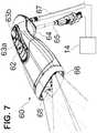
- FIG. 7illustrates an enclosure according to an embodiment
- FIGS. 8A and 8Billustrate perspective views of different exemplary positions in which the system may be used
- FIG. 9Aillustrates a drape for use with the system according to an embodiment
- FIGS. 9B to 9Eillustrate perspective, front, top, and side views, respectively, of a drape lens and frame for use with the system according to an embodiment
- FIG. 9Fillustrates a drape lens and frame installed on an enclosure of the system, according to an embodiment
- FIG. 9Gillustrates a section view of the installed drape lens and frame on the enclosure of the system of FIG. 9F ;
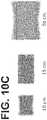
- FIGS. 10A to 10Dillustrate illumination distributions for different illumination configurations
- FIG. 11Aillustrates a timing diagram for visible and excitation illumination and image sensor exposures according to an embodiment
- FIG. 11Billustrates a timing diagram for visible and excitation illumination and image sensor exposures according to an embodiment
- FIG. 11Cillustrates a timing diagram for visible and excitation illumination and image sensor exposures according to an embodiment
- FIG. 11Dillustrates a timing diagram for visible and excitation illumination and image sensor exposures according to an embodiment
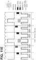
- FIG. 11Eillustrates a timing diagram for visible and excitation illumination, image sensor exposures and ambient light measurement according to an embodiment
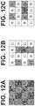
- FIGS. 12A to 12Cillustrate pixel layout and an interpolation scheme according to an embodiment
- FIGS. 13A to 13Cillustrate diagrams of an embodiment of a display method output when a target reticle is placed over regions with no fluorescence intensity, high relative normalized fluorescence intensity, and moderate relative normalized fluorescence intensity, respectively;
- FIG. 13Dillustrates a diagram of an embodiment of a display method output that includes a signal time history plot of normalized fluorescence intensity values on the display;
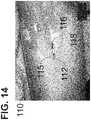
- FIG. 14illustrates a recorded image of an anatomical fluorescence imaging phantom, featuring an embodiment of a display method output that displays normalized fluorescence intensity
- FIG. 15illustrates an exemplary light source of an exemplary illumination source of the system for illumination shown in FIG. 1 ;
- FIG. 16illustrates an exemplary imaging module of the fluorescence imaging system in FIG. 1 , the imaging module comprising a camera module;
- FIG. 17Aillustrates a perspective top view of an illumination and imaging system according to an embodiment
- FIG. 17Billustrates a schematic side view of a movable filter assembly for the illumination and imaging system of FIG. 17A , according to an embodiment
- FIGS. 17C to 17Dillustrate an enclosure according to an embodiment
- FIG. 17Eillustrates a sensor and light source arrangement in a forward portion of an enclosure according to an embodiment
- FIG. 18illustrates a schematic diagram of components of an illumination and imaging system according to an embodiment
- FIG. 19illustrates a schematic diagram of a drape detection module according to an embodiment.
- spatially relative termssuch as “beneath”, “below”, “lower”, “above”, “upper”, and the like, may be used herein for ease of description to describe one element or feature's relationship to another element(s) or feature(s) as illustrated in the figures. It will be understood that the spatially relative terms are intended to encompass different orientations of the device in use or operation in addition to the orientation depicted in the figures. For example, if the device in the figures is turned over, elements described as “below” or “beneath” other elements or features would then be oriented “above” the other elements or features. Thus, the exemplary term “below” can encompass both an orientation of above and below. The device may be otherwise oriented (rotated 90 degrees or at other orientations) and the spatially relative descriptors used herein interpreted accordingly.
- FIG. 1illustrates a schematic view of an illumination and imaging system 10 according to an embodiment.
- the system 10may include an illumination module 11 , an imaging module 13 , and a video processor/illuminator (VPI) 14 .
- the VPI 14may include an illumination source 15 to provide illumination to the illumination module 11 and a processor assembly 16 to send control signals and to receive data about light detected by the imaging module 13 from a target 12 illuminated by light output by the illumination module 11 .
- the video processor/illuminator 14may comprise a separately housed illumination source 15 and the processor assembly 16 .
- the video processor/illuminator 14may comprise the processor assembly 16 while one or more illumination sources 15 are separately contained within the housing of the illumination module 11 .
- the illumination source 15may output light at different waveband regions, e.g., white (RGB) light, excitation light to induce fluorescence in the target 12 , a combination thereof, and so forth, depending on characteristics to be examined and the material of the target 12 . Light at different wavebands may be output by the illumination source 15 simultaneously, sequentially, or both.
- the illumination and imaging system 10may be used, for example, to facilitate medical (e.g., surgical) decision making e.g., during a surgical procedure.
- the target 12may be a topographically complex target, e.g., a biological material including tissue, an anatomical structure, other objects with contours and shapes resulting in shadowing when illuminated, and so forth.
- the VPI 14may record, process, display, and so forth, the resulting images and associated information.
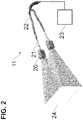
- FIG. 2illustrates a schematic perspective view of the illumination module 11 of FIG. 1 according to an embodiment.
- the illumination module 11may include at least two illumination ports directing illumination from an illumination source 23 , which may be included in the VPI box 14 , to for example a rectangular target field 24 .
- the illumination source 23may be located in a device housing along with the illumination module 11 .
- Each illumination portis to provide illumination over the target field 24 , such that the light overlaps, e.g., substantially or completely, at the target material 12 (shown in FIG. 1 ). More than two illumination ports may be used.
- the illumination distributionsmay be substantially similar and overlap (e.g., substantially or completely) at the target 12 to provide uniform illumination of the target 12 .
- illumination from the illumination module 11may be directed to provide uniform illumination of the target 12 without matching the region of illumination to a rectangular imaging field of view, and the rectangular target field 24 of FIG. 2 may be replaced by a non-rectangular target field.
- a light pipemay be used to achieve mixing of the illumination light in order to yield a uniform illumination profile. Mixing of the illumination light by a light pipe may remove the influence of the structure of the light source on the illumination profile, which could otherwise adversely affect uniformity of the illumination profile. For example, using a light pipe to mix the illumination light output from a fiber optic light guide may remove images of the structure of the individual optical fibers from the illumination profile.
- a rectangular light pipemay be used to efficiently utilize illumination power while matching the illumination profile to a rectangular imaging field of view.
- a light pipe material with a high index of refraction for both visible light and near infrared lightsuch as optical glass material N-SF11, may be used for high efficiency of illumination power transmission.
- a rectangular light pipe with an aspect ratio matching the aspect ratio of the imaging field of viewmay be used in conjunction with rotationally symmetric illumination optic elements.
- a rectangular light pipe with a different aspect ratio than the imaging field of viewmay be used in conjunction with cylindrical illumination optic elements.
- Cylindrical optic elementsmay be used to separately conform one or both dimensions of the rectangular illumination profile to match the aspect ratio of the imaging field of view.
- various approachesmay be used for matching the illumination to overlap the imaging field of view.
- applications which require a large range in working distances and high illumination uniformitymay necessitate use of illumination optics and/or ports that are steered dynamically to adequately match the illumination to the imaging field of view, while applications with lower requirements may be served with fixed illumination optics and/or ports to match the illumination to the field of view.
- the direction of illuminationis adjusted from multiple illumination ports in synchrony with adjustment of the field of view, in order to steer the field of illumination to maintain correspondence to the field of view.
- one or more illumination optic elementsmay be rotated by a driver in order to steer the illumination.
- one or more illumination optic elementsmay be translated perpendicular to the imaging optic axis by a driver in order to steer the illumination.
- one or more illumination optic elementsmay be configured to provide some distortion in the illumination profile, in order to account for distortion inherent to the accompanying imaging system.
- uniform illumination of the imaging field of view over a specified range of working distancesmay be achieved with a fixed location and orientation of the illumination optics.
- the offset distance of the illumination optics from the imaging optic axismay be configured, along with the orientation of the of the illumination optics, in order to optimize matching of the illumination profile to the imaging field of view at a working distance within the specified range of working distances while also maintaining substantial matching of the illumination profile to the imaging field of view at other working distances within the specified range.
- each illumination portmay include a lens module 20 , a connecting cable 22 connected to the illumination light source 23 , and a light pipe 21 adapting a high numerical aperture of the connecting cable 22 to a lower numerical aperture of the lens module 20 .
- the lens module 20may be steerable, as described in detail below. In some scenarios, acceptable performance may be achievable without steering.
- an illumination module, and imaging device having the samethat provides an illumination field having a rectangular form factor (or configuration other than rectangular) that matches the field of view of the imaging system using at least two illumination ports in which each port produces a gradient of illumination such that the sum illumination flux in the object plane is reasonably the same at each point in the illumination field, e.g., provides uniform illumination over the imaging field of view, alone may be sufficient.
- the connecting cable 22 from FIG. 2may be replaced by one or more illumination light sources 23 .
- the connecting cable 22 and the light pipes 21 from FIG. 2may be replaced by one or more illumination light sources 23 .
- the lens module 20 from FIG. 2may contain the illumination light source 23 .
- separate variants of the lens module 20 from FIG. 2may separately contain a white light source and a fluorescence excitation light source of the illumination light source 23 .
- three or more lens modules 20may be arranged to comprise a ring of illumination ports, another functionally equivalent configuration of illumination ports, or another configuration including continuous or non-continuous distribution/arrangement of illumination ports, with each lens module 20 oriented to converge on and provide uniform illumination over the imaging field of view.
- the three or more lens modules 20 comprising a ring of illumination portsmay not necessarily constrain illumination to a rectangular field, and the rectangular target field 24 of FIG. 2 may be replaced by a non-rectangular target field, such as for example a circular/oval target field.
- FIGS. 3A and 3Billustrate a side view and a plan view, respectively, of the lens module 20 .
- the lens module 20may include lenses mounted in a steerable lens housing 30 .
- a lensis any optical element having optical power, whether implemented by a refractive or diffractive element.
- the lensesmay include a pair of horizontal-axis cylindrical lenses 31 - 32 and a pair of vertical-axis cylindrical lenses 33 - 34 .
- a prism element 35is also shown which may align illumination light with the intended outgoing optical axis.
- the prism element 35corrects for an angle introduced by the light pipe 21 for increased device compactness in accordance with an embodiment.
- the mounting design for each lens element 31 - 35may allow for tuning of the magnification and focus of the illumination optical system.
- the steerable lens housing 30encloses and steers three of the cylindrical lenses 31 , 33 , 34 and the prism lens element 35 , e.g., collectively as a group.
- This example of lensesis merely illustrative, and the lenses in the lens module 20 may be modified as appropriate.
- a base portion of the steerable housing 30is pinned, e.g., using a pin 46 (see FIG. 6B ) inserted into housing hole 37 , about a pivot point 36 , respectively to a fixed chassis frame 90 (see FIG. 6A ) and a mechanical linkage 40 (see FIGS. 4A to 4C ) described in detail below, while lens 32 is rigidly connected the chassis 90 , i.e. not to the housing 30 (see FIG. 6B ).
- FIG. 4Aillustrates a schematic view showing directions of motion provided by various components of the linkage 40 .
- the linkage 40may include a drive cam 41 , illumination cams 45 a , 45 b (one for each illumination port), and an imaging cam 43 .
- the drive cam 41receives an input from a user (see FIG. 7 ), and translates that to synchronous motion of the lens module 20 a , 20 b , attached to a corresponding illumination cam 45 a , 45 b , via a respective housing 30 (see FIG. 3B ) and a pin 46 (see FIG. 6B ), and an imaging lens 51 and an imaging sensor 52 (see FIGS. 5A and 5B ), attached to the imaging cam 43 via cam follower pins.
- the imaging lens 51is shown as a single field lens, but additional and/or alternative lenses for focusing light from the target 20 onto the imaging sensor 52 may be employed.
- Each porthas its own associated illumination cam 45 A or 45 B, here shown as being to a left and right of an input window to receive light from the target 12 .
- drive cam 41is shown as a plate with a front edge extending beyond the rear of the lens modules 20 a , 20 b , but the drive cam 41 need not be in the form of a plate and may instead comprise multiple surfaces to interface with and drive three or more lens modules, in which case the front edge of the drive cam 41 and the rear edges of illumination cams 45 a , 45 b may be set further to the rear in order to accommodate additional lens modules and corresponding illumination cams.
- translation of the drive cam 41may translate the imaging cam 43 along the x-axis, which, in turn, may result in the imaging cam 43 to translate the imaging lens 51 and the imaging sensor 52 along the z-axis, as well as translate the illumination cams 45 a , 45 b , which, in turn, simultaneously steer corresponding lens modules 20 a , 20 b about respective pivot points 36 , such that steering of the lens modules 20 a , 20 b is synchronously performed with the position adjustment of the imaging lens 51 and the imaging sensor 52 to insure proper focus of light from the target onto the sensor 52 .
- the imaging cam 43may translate only the imaging lens 51 along the z-axis, or any other combination of imaging optical elements in order to insure proper focus of light from the target onto the sensor 52 .
- FIG. 4Billustrates a bottom view
- FIG. 4Cillustrates a top view of the linkage 40 according to an embodiment.
- the drive cam 41may include two drive parts 41 a and 41 b , and, if steering is included, a third drive part 41 c , all of which are shown here as being rigidly attached to form a rigid drive cam 41 .
- the imaging cam 43may include two imaging parts 43 a and 43 b .
- the drive cam 41receives the input from a user (via control surface 62 ) via the first drive part 41 a and translates the imaging cam 43 via a cam follower pin in drive part 41 b , resulting in the imaging cam part 43 a translating the sensor 52 and the imaging cam part 43 b translating the imaging lens 51 .
- the third drive part 41 csimultaneously steers (rotates) the lens modules 20 a , 20 b using the pin 46 (see FIG. 6B ) associated with each of the illumination cam parts 45 a and 45 b , by translating the illumination cam parts 45 a and 45 b .
- the pin 46may be inserted through a through a slot 49 in each of the illumination cams 45 a , 45 b and the corresponding housing hole 37 in the lens modules 20 a , 20 b .
- the drive part 41 csteers the lens modules 20 a , 20 b simultaneously such that they both still illuminate a same field of view as one another at the target field of view of the target 12 .
- FIGS. 5A and 5Billustrate bottom views of the linkage combined with the lens modules 20 a , 20 b , the imaging field lens 51 , and the sensor 52 , at a far working distance and a near working distance, respectively, according to an embodiment.
- the linkage 40synchronizes steering of the illumination sources with focusing of the imaging system at two sample working distance illumination steering settings.
- FIGS. 5A-5Bshow the positions of lens modules 20 a , 20 b (rotated about the pivot pint 37 ) and the lens 51 and sensor 52 (translated along an optical axis 55 of the imaging system and along the x-axis) at two focus positions resulting from user input.
- each part that moves axially within the linkage mechanism 40may be guided by two fixed rolling elements 47 , and one spring-loaded rolling element 48 , in order to reduce or minimize friction during motion.
- the linkage 40also may include a drive cam input connection point 42 .
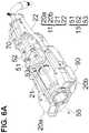
- FIGS. 6A and 6Billustrate a perspective top view and a perspective bottom top view of the device 10 in accordance with an embodiment.
- the illumination module 11 and the imaging module 13are mounted on the chassis 90 , the top portion of which is removed in for clarity.
- a focus actuation mechanism 70is illustrated, which translates motion from user input to motion of the drive cam 41 via the drive cam input connection point 42 .
- an optical axis 55 of the imaging module 13runs through a center of the imaging module, with the lens modules 20 a , 20 b being arranged symmetrically relative to the imaging optical axis 55 .
- the light to be imaged from the target 12travels along the optical axis 55 to be incident on the lens 51 and sensor 52 .
- a wavelength-dependent aperture 53that includes a smaller central aperture that permits transmission of all visible and fluoresced light, e.g., near infrared (NIR) light, and a surrounding larger aperture that blocks visible light but permits transmission of fluoresced light, may be provided upstream of the lens 51 .
- NIRnear infrared
- the pin 46connects the lens module 20 , via the housing hole 37 in the housing 30 , slot 49 of the linkage 40 . Also, a pivot point pin 44 connects the lens module 20 to the chassis 90 .
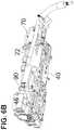
- FIG. 7illustrates an embodiment of an ergonomic enclosure 60 enclosing the illumination module 11 and the imaging module 13 .
- the ergonomic enclosure 60is designed to be held in different use-modes/configurations, for example, a pistol-style grip for forward imaging in a scanning-imaging orientation ( FIG. 8A ), and a vertical-orientation grip for use when imaging downward in an overhead imaging orientation ( FIG. 8B ).
- the enclosure 60includes a control surface 62 , a grip detail 64 , a window frame 68 and a nosepiece 66 .
- the ergonomic enclosure 60is connectable to the VPI box 14 via a light guide cable 67 , through which the light is provided to the illumination ports 20 a , 20 b , and a data cable 65 that transmits power, sensor data, and any other (non-light) connections.
- the control surface 62includes focus buttons 63 a (decreasing the working distance) and 63 b (increasing the working distance) that control the linkage 40 .
- Other buttons on the control surface 62may be programmable and may be used for various other functions, e.g., excitation laser power on/off, display mode selection, white light imaging white balance, saving a screenshot, and so forth.
- a proximity sensormay be provided on the enclosure and may be employed to automatically adjust the linkage 40 .
- the enclosure 60when the enclosure 60 is held with the imaging window facing forward, the thumb rests on the control surface 62 while the other fingers on the operator's hand are wrapped loosely around the bottom of the grip detail 64 .
- the grip detail 64when the enclosure 60 is held with the imaging window facing downward, the grip detail 64 is between the thumb and index finger and the fingers are wrapped around to access the control buttons or switches on the control surface 62 .
- the grip detail 64is sculpted so as to provide for partial support of the device weight on the top of the wrist in the vertical-orientation grip, such that the enclosure 60 can hang loosely and without the need for a tight grip of the enclosure 60 .
- the enclosure 60may be operated by a single hand in multiple orientations.
- the enclosure 60may be supported on a support (e.g., a movable support).
- the window frame 68defines the different windows for the enclosure 60 .
- the window frame 68defines windows 68 a and 68 b , corresponding to the two lens modules 20 a and 20 b , as well as window 68 c , which serves as an input window for light from the target to be incident on the sensor 52 .
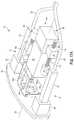
- FIGS. 17A-Dillustrate an imaging system 300 in accordance with one embodiment.
- Imaging system 300may include one or more components of imaging system 10 of FIG. 1 .
- imaging system 300may comprise illumination module 11 and imaging module 13 of system 10 .
- System 300may be used for or with any of the methods and processes described herein with respect to system 10 .
- imaging system 300includes two illumination ports 311 , imaging module 313 , and plate 302 , each of which is mounted to a frame or chassis (not shown).
- the light to be imaged from target 12which may include light from illumination ports 311 reflected by target 12 and/or fluorescent light emitted from target 12 , travels along the optical axis 355 , through plate 302 and into imaging module 313 , which houses one or more imaging sensors.
- imaging module 313may include movable filters for filtering light that enters the imaging module.
- the imaging module 313may include one or more wavelength-dependent apertures that includes a smaller central aperture that permits transmission of all visible and fluoresced light, e.g., NIR light, and a surrounding larger aperture that blocks visible light but permits transmission of fluoresced light.
- Each illumination port 311includes a lens module 320 , a connecting cable 322 connected to the illumination light source 23 , and a light pipe 321 adapting a high numerical aperture of the connecting cable 322 to a lower numerical aperture of the lens module 320 .
- the lens modules 320may provide illumination having a rectangular form factor that matches the field of view of the imaging system 300 .
- Each illumination port 311may produce a gradient of illumination such that the sum illumination flux in the object plane is reasonably the same at each point in the illumination field, e.g., providing uniform illumination over the imaging field of view.
- Lens modules 320each include one or more lenses and/or prism elements for shaping and orienting illumination to meet application requirements.
- the two illumination ports 311lie horizontally offset from the center of the optical axis 355 of the imaging system 300 , prisms may be included in the lens modules 320 to direct the beams towards the center of the field of view.
- the degree of directionmay be tailored to the specific application, or to a set of specific applications. For example, in some variations, the degree of direction is selected such that the beams overlap at a nominal imaging distance of 25 cm. In some variations, the horizontal offset of the illumination ports 311 and the degree of direction are selected such that the beams substantially overlap and substantially cover the field of view over a range of working distances, such as distances from 18-40 cm.
- the illumination portsare fixed with respect to the frame. In other embodiments, the illumination ports are steerable, in accordance with the principles described above.
- Imaging module 313includes image sensor assembly 352 , optics module 351 , and movable filter assembly 330 aligned along an optical axis 355 .
- the image sensor assembly 352which includes an image sensor and may include one or more lenses, filters, or other optical components, is movable relative to the frame along the optical axis 355 via focus actuation assembly 370 .
- Focus actuation assembly 370includes lead nut 372 affixed to the housing of the image sensor assembly 352 .
- the lead nut 372is coupled to lead screw 374 , which extends from focus motor 376 .
- Focus motor 376is fixed to the frame and can be actuated in forward and reverse directions to turn lead screw 374 , which causes lead nut 372 to translate along the lead screw axis, moving image sensor assembly 352 forward and backward along the optical axis 355 .
- Lead nut 372 and/or focus actuation assembly 370may be mounted on shafts that slide within mountings on the frame, for example, using one or more linear ball bearings or bushings to restrain lateral and angular play.
- the image sensor assembly 352may comprise a single image sensor that is configured to detect light from the target resulting from illumination by visible light and excitation light.
- the image sensor assembly 352may comprise multiple image sensors for.
- the image sensor assembly 352may comprise separate image sensors configured to detect light from the target resulting from illumination by visible light separately from that resulting from illumination by excitation light.
- a controllermay be used to control movement of the image sensor assembly 352 for focusing, which may be based on user input.
- system 300may be provided with one or more controls such as buttons or touch screen controls to enable the user to adjust the focus.
- a usermay actuate a focus control until the desired focus is achieved or may enter a value associated with a desired focus and the controller may actuate the image sensor assembly 352 until the desired focus is achieved.
- a magnetic position sensor mounted on the housing of the image sensor assembly 352detects the position of the image sensor assembly 352 for closed loop control of focus actuation assembly 370 by the controller.
- the controllercan use open loop control of focus actuation assembly 370 , for example, by using a stepper motor.
- Optics module 351which is located forward of image sensor assembly 352 , is fixed relative to the frame and may include one or more optical components (e.g., lenses, apertures, filters, etc.) for adjusting light traveling along the optical path before reaching the image sensor.
- optics module 351may include a wavelength-dependent aperture (e.g., similar to aperture 53 of FIG. 6A ) that includes a smaller central aperture that permits transmission of all visible and fluoresced light, e.g., NIR light, and a surrounding larger aperture that blocks visible light but permits transmission of fluoresced light.
- Movable filter assembly 330is located forward (upstream with respect to the direction of travel of light from a target to the image sensor) of optics module 351 and includes first window 334 a and second window 334 b , each of which is housed in a bracket (first window bracket 332 a and second window bracket 332 b , respectively).
- First and second windows 334 a , 334 bcan be alternately moved into and out of the optical path.
- the first and second windows 334 a , 334 bcan be alternately moved into and out of the optical path via linkage assembly 336 , which is actuated by filter motor 338 .
- the first and/or second windowscan be moved via any combination of motions including rotation (for example on a rotary wheel) and/or translation.
- One or both of the windows 334 a , 334 bcan include filters for filtering light before it reaches the image sensor. By moving filters into and out of the optical path, imaging system 300 can be operated in different imaging modes.
- one of the windowse.g., first window 334 a
- the other windowe.g., second window 334 b
- the imaging systemcan be operated in a first mode and, with the clear glass in the optical path, the imaging system can be operated in a second mode.
- one windowmoves into the optical path while the other window moves out of the optical path.
- a visible-light rejection filterwhich only transmits NIR light between 830-900 nm is included in a first window for a fluorescence-only imaging mode and an anti-reflective coated glass plate, which passes all light, is included in the second window for use in a second mode.
- the glass platecan ensure the same optical path length regardless of mode.
- a controller of system 300can control movable filter assembly 330 to change modes, for example, in response to a user input.
- second window bracket 332 bis in a deployed position such that second window 334 b is positioned in the optical path and is oriented perpendicularly to the optical axis 355 .
- filter motor 338which actuates linkage assembly 336
- the second window bracket 332 b and second window 334 bmove out of the optical path by pivoting about a pivot axis that extends perpendicularly to optical axis 355 .
- first window bracket 332 a and first window 334 amove into the optical path by pivoting about a pivot axis that extends perpendicularly to optical axis 355 .
- the pivot axis of the first window bracket and the pivot axis of the second window bracketare vertically aligned and the first and second window brackets and window are symmetrical to provide matching optical path lengths regardless of mode.
- Linkage assembly 336is actuated by filter motor 338 , which may be controlled by a controller of system 300 .
- Filter motor 338rotates filter lead screw 341 , which moves filter lead nut 342 forward and rearward.
- Linkage 344is pivotally connected on a first end to filter lead nut 342 and pivotally connected at a second end to slider 346 a .
- a pivot link 348 ais pivotally connected at one end to slider 346 a and at the other end to first window bracket 332 a .
- slider 346 b and pivot link 348 b(which are not shown in FIG. 17A ) are provided below slider 346 a and pivot link 348 a for actuating second window bracket 332 b.
- Movable filter assembly 330is schematically depicted in FIG. 17B .
- Filter motor 338which is fixed relative to the frame, rotates the filter lead screw 341 clockwise and counterclockwise, causing filter lead nut 342 to translate forward and rearward along the filter lead screw axis.
- Translation of filter lead nut 342causes translation of slider 346 a via linkage 344 .
- Translation of slider 346 acauses translation of pivot link 348 a .
- Pivot link 348 ais pivotally connected to first window bracket 332 a at a location off-center from the pivot connection 349 a of first window bracket 332 a to the frame. Therefore, movement of pivot link 348 a causes rotation of first window bracket 332 a .
- translation of slider 346 a forwardcauses first window bracket 332 a to rotate 90 degrees out of the optical path.
- Driving linkage 345is pivotally connected at a first end to linkage 344 , pinned to the frame at connection point 345 a , and pivotally connected at a second end to slider 346 b .
- translation of linkage 344causes rotation of driving linkage 345 , which translates slider 346 b .
- Slider 346 bis connected to second window bracket 332 b via pivot link 348 b , which is pivotally connected to second window bracket 332 b at a location off-center from the pivot connection 349 b of second window bracket 332 b to the frame.
- pivot link 348 bwhich is pivotally connected to second window bracket 332 b at a location off-center from the pivot connection 349 b of second window bracket 332 b to the frame.
- translation of slider 346 bcauses rotation of second window bracket 332 b . From the configuration of FIG.
- Plate 302is a flat plate for sealing the housing and protecting the illumination and imaging optics.
- plate 302is a single plate of glass.
- One or more optical componentssuch as a lens may be mounted between the glass plate and the movable filter assembly 330 .
- one or more sensorsare positioned on the rear side of plate 302 to measure light incident on plate 302 .
- One or more of these sensorsmay detect ambient light, light reflected from the target, light emitted by the target, and/or light reflected from non-target objects.
- a drape detectoris included to detect the presence of a drape.
- the drape detectormay include, for example, an infrared emitter and a photodetector that detects infrared light reflected by a drape positioned on the imaging system.
- FIGS. 17C-Dillustrate an embodiment of an ergonomic enclosure 360 enclosing illumination ports 311 and imaging module 313 , according to one variation.
- the ergonomic enclosure 360is designed to be held in a pistol-style grip.
- the enclosure 360may include a control surface 362 , a grip 364 , a window frame 368 and a nosepiece 366 .
- the ergonomic enclosure 360is connectable to the VPI box 14 via a light guide cable 367 , through which the light is provided to illumination ports 311 , and a data cable 365 that transmits power, sensor data, and any other (non-light) connections.
- the control surface 362includes focus buttons 363 a and 363 b that control the focus actuation assembly 370 .
- Other buttons on the control surface 362may be programmable and may be used for various other functions, e.g., excitation laser power on/off, display mode selection, white light imaging white balance, saving a screenshot, and so forth.
- a proximity sensormay be provided on the enclosure and may be employed to automatically adjust the focus actuation assembly 370 .
- Enclosure 360may be operated by a single hand in a pistol-grip style orientation. In various other embodiments, the enclosure 360 may be supported on a support (e.g., a movable support). In some embodiments, enclosure 360 may be used in concert with a drape, such as drape 80 of FIG. 9A or drape 390 of FIG. 9B .
- a drapesuch as drape 80 of FIG. 9A or drape 390 of FIG. 9B .
- a window frame 368is provided on the forward portion of enclosure 360 in front of plate 302 .
- the window frame 368is provided on the forward portion of enclosure 360 behind plate 302 , and plate 302 provides the outer surface of the enclosure.
- no frameis provided and plate 302 provides the outer surface of the enclosure.
- Window frame 368may include windows 368 a and 368 b , corresponding to the two lens modules 320 , as well as window 368 c , which serves as an input window for light from the target to be incident on the image sensor.
- Window frame 368may also include one or more windows 369 for sensors provided behind plate 302 .
- FIG. 17Eillustrates an embodiment of a sensor arrangement provided behind plate 302 on the forward portion of enclosure 360 , according to one variation.
- a central sensor group 391comprising one or more sensors 392 is provided in order to detect reflected illumination light for input to an automatic gain control function, as described below.
- peripheral sensor groups 393 a and 393 beach comprising one or more sensors 394 , are provided in order to detect reflected illumination light for purposes of proximity detection to the imaging target or to detect any objects near to the forward portion of the enclosure 360 , as described below.
- the source of the illumination light for proximity detectionmay be either the main illumination beam or may be one or more dedicated emitters for proximity detection.
- one or more sensors 387 and one or more light sources 386are provided in order to detect the presence of an installed drape lens, as described below. Also in this embodiment, one or more sensors 395 may be provided in order to detect ambient room light intensity to facilitate correction of image intensity artifacts arising from pulsating room light components, as described herein.
- the sensors 392may be used to detect reflected light levels in order to provide input for an automatic gain control (AGC) function (see FIG. 18 ) that may be used to facilitate optimizing illumination and imaging parameters and providing a consistent and/or smoothly varying image brightness, even when varying the working distance.
- AGCautomatic gain control
- AGCmay also be used to facilitate optimizing or maximizing the image signal to noise ratio, or to minimize the illumination intensity to facilitate minimizing photo-bleaching.
- the AGCmay be used to dynamically adjust image signal gain, illumination pulse duration, exposure, and/or illumination power.
- the reflected illumination light detected by the sensors 392may include visible light and/or fluorescence excitation light, such as NIR light.
- sensors 392are sensitive to NIR light but not to visible light, such that ambient visible light and white light illumination do not contribute to the light level signal from sensors 392 .
- sensors 392are comprised of photodiodes.
- the reflected light level sensors 392may be used as input to AGC in any imaging mode, including a white light imaging mode and/or a multiplexed combined white light and fluorescence imaging mode, and may be particularly important in a fluorescence-only imaging mode.
- a fluorescence-only imaging modefor example with filter 334 a blocking visible light from reaching the image sensor, no reflected white light luminance image is recorded, which could otherwise be used as an input to AGC, while the recorded fluorescence image necessarily excludes reflected fluorescence excitation light (which would otherwise overpower the fluorescence signal) through use of a notch filter in the imaging optics. Therefore, the sensors 392 may provide the only measure of reflected light.
- the operation of AGC in a fluorescence-only imaging modeprioritizes maximizing the exposure duration and minimizing the gain.
- the gain, excitation period (which may, for example, be the same as the image sensor exposure time) and instantaneous excitation powercan be adjusted as follows in order to achieve a constant image brightness for a given fluorescence sample regardless of working distance.
- the priorities of adjusting T, G and Pcan be optimized to minimize noise while limiting maximum exposure of tissue to excitation light.
- the sensors 392are arranged such that their detection cones approximately cover the imaging field of view.
- a sensor group 391is comprised of four sensors 392 arranged in a rectangular pattern surrounding the imaging port.
- AGCoperates by starting with settings for an initial gain g o , initial exposure e o , and initial illumination power p o .
- User defined brightness parametersmay prescribe target values, such as for example, a target peak brightness P t and a target mean brightness M t , as well as a choice of AGC mode to be based on the peak values, mean values, or a balanced combination of both peak and mean values.
- a peak sensor brightness P smay be calculated based on a peak signal from among sensors 392 during the acquisition duration, and a mean sensor brightness M s may be calculated based on a mean of the signals from sensors 392 during the duration.
- An adjustment factor Fis then calculated based on these values and used to calculate a target exposure value e t and a target gain value g t .
- peak mode FP t /P s
- the excitation powermay be adjusted as a lowest adjustment priority.
- the new values for exposure, gain, and powerare treated as the current values for the next AGC cycle.
- the sensors 394may be used to detect reflected illumination light that is reflected off of objects entering into the periphery of the illumination beams and located near to the front of the enclosure 360 . For example, detection of such near objects may be used to trigger switching to a reduced illumination power setting in order to reduce a possible safety risk from high illumination power being delivered to a nearby object.
- the reflected illumination light detected by sensors 394may include visible light and/or fluorescence excitation light, such as NIR light.
- sensors 394are sensitive to NIR light but not to visible light, such that ambient visible light and white light illumination do not contribute to the detection signal from sensors 394 .
- sensors 394are comprised of photodiodes or of time-of-flight sensors.
- the sensors 394are arranged such that they may detect objects entering the illumination beams which are not within the imaging field of view.
- a method for imaging a targetincludes illuminating the target with an illuminator of an imaging system, such as illumination ports 311 of imaging system 300 , and receiving light from the target at an imaging sensor of the imaging system in an unrestricted imaging mode.
- the light received from the targetinclude light reflected by the target and light emitted by the target.
- the reflected lightincludes visible light and the emitted light includes fluorescent light from the target.
- the imaging modeis switched from the unrestricted imaging mode to a restricted imaging mode in which light of wavelengths outside of a desired wavelength band or bands is blocked from reaching the imaging sensor. The light is blocked using a movable filter of the imaging device. The light that is passed by the filter is received by the imaging sensor.
- the imaging modecan be switched back to the unrestricted imaging mode in which the filter is moved out of the optical path so that it no longer blocks light in the optical path.
- system 300can be operated in an unrestricted imaging mode in which first window 334 a is in a deployed position in the optical path.
- First window 334 amay include a clear plate that permits all light to pass through it.
- the image sensormay receive all or most of the light that reaches first window 334 a .
- System 300can be switched to a restricted imaging mode in which the first window 334 a is in a stowed position out of the optical path and the second window 334 b is in a deployed position in the optical path, according to the principles described above.
- the second window 334 bmay include a filter that filters out light that is not in a desired wavelength band or set of wavelength bands.
- the filtermay filter out all visible light but pass infrared light (e.g., NIR light).
- the imaging sensorprovides imaging data of only the light passed by the filter.
- System 300may be switched to the restricted imaging mode in response to a request that may be received from a user (e.g., via actuation of one or more buttons on the control surface 362 ) or that may be received from an external control system.
- a usere.g., via actuation of one or more buttons on the control surface 362
- an external control systeme.g., via actuation of one or more buttons on the control surface 362
- the systemcan switch between two restricted imaging modes by including a first filter configured to block a first wavelength band or set of wavelength bands and a second filter, different from the first, that is configured to block a different wavelength band or set of wavelength bands from the first.
- the automatic gain control process described abovecan be started upon switching to the restricted imaging mode and may be stopped upon switching to the unrestricted imaging mode (e.g., AGC can be automatically started and stopped by a controller of the system 300 ). In other embodiments, AGC is performed during both the restricted and unrestricted imaging modes.
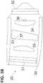
- the enclosure 60 of FIG. 7may be used in concert with a drape 80 .
- the drape 80may be a surgical drape suitable for use during a surgical procedure.
- the drapeincludes drape material 81 , a drape lens 82 , a drape window frame 83 surrounding the drape lens, and an interlock interface 84 that is integral with the drape window frame 83 .
- the drape material 81is to envelope the device in the enclosure 60 , as well as to cover anything else as required.
- the drape window frame 83may follow a shape of the enclosure nosepiece 66 such that the drape window frame 83 may be inserted therein without obstructing the windows 68 a to 68 c .
- the drape 80is designed to minimize reflections and imaging ghosting by ensuring the drape lens 82 is flush, e.g., to within 0.5 mm, with the imaging and illumination window frame 68 .
- the drape 80may use the interlock interface 84 , which may fit over a ridge on the inner surface of the enclosure nosepiece 66 , to be secured flush thereto. In one variation, the interlock interface 84 may fit into a recess on the inner surface of the enclosure nosepiece 66 .
- One or more interlock interfaces 84may be used on the inner or outer surface of the enclosure nosepiece 66 , in order to ensure a secure and close fit of the drape lens 82 against the window frame 68 .
- two interfaces 84here one on the top and one on the bottom of the drape window frame 83 to engage with an inner surface of the enclosure nosepiece 66 , are used.
- feedbackmay be provided to the user to indicate when the drape lens has been installed correctly onto the enclosure nosepiece.
- a raised ridge around at least a portion of the drape window framemay provide tactile and/or aural feedback when pushed over one or more detent features on the interior surface of the enclosure nosepiece.
- a raised ridge around at least a portion of the drape window framemay provide tactile and/or aural feedback when pushed over one or more detent features on the exterior surface of the enclosure nosepiece.
- one or more interlock interfacesmay provide tactile and/or aural feedback when pushed into place to engage with an inner surface of the enclosure nosepiece.
- one or more interlock interfacesmay provide tactile and/or aural feedback when pushed into place to engage with an outer surface of the enclosure nosepiece.
- a drape detection moduleas described below, may provide feedback to indicate when the drape lens has been installed correctly.
- the drapemay be symmetrical such that it may be rotated by 180 degrees about its central axis (e.g., the axis aligned with the imaging optical axis) and may be installed correctly onto the enclosure nosepiece both before and after such a rotation.
- its central axise.g., the axis aligned with the imaging optical axis
- the drape lens materialmay comprise a transparent polymer material such as, for example, polymethyl methacrylate (PMMA), polycarbonate, polyvinyl chloride, or polyethylene terephthalate glycol-modified.
- the drape lens materialmay be chosen based in part on having a relatively low refractive index and high light transmission in the visible and NIR bands compared to other candidate materials, so as to minimize artifacts caused by reflections at the drape lens and to maximise illumination and imaging transmission.
- the drape lens materialsuch as PMMA, may have an index of refraction of less than about 1.5 and light transmission greater than about 92% in the visible and NIR bands.
- the drape lens and/or the drape window framemay be manufactured by injection molding.
- the drape lensmay be coated with an anti-reflection coating to reduce imaging and illumination artifacts from reflection at the window.
- FIGS. 9B-Gillustrate an embodiment of a drape 390 comprising drape lens 380 and drape window frame 381 to be used in combination with drape material (not shown), such as drape material 81 (see FIG. 9A ), to cover the enclosure 360 of FIG. 17C-D .
- the drape 390may be a surgical drape suitable for use during a surgical procedure.
- the drapeincludes drape material (not shown), a drape lens 380 , a drape window frame 381 surrounding the drape lens, an interlock interface 384 that is integral with the drape window frame 381 , and a reflective feature 388 .
- the drape materialis to envelope the device in the enclosure 360 , as well as to cover anything else as required.
- the drape window frame 381may follow a shape of a forward portion of the enclosure 360 such that the drape window frame 381 may be inserted thereon.
- the drape 390is designed to minimize reflections and imaging ghosting by ensuring the drape lens 380 is flush, e.g., to within 0.5 mm, with the front surface of the enclosure 360 , such as plate 302 of FIGS. 17A-B .
- the drape 390may use the interlock interface 384 , which may fit into over a ridge 383 on the inner surface of the front portion of the enclosure 360 , to be secured flush thereto.
- a drape detection modulemay be provided to detect the installation of the drape lens onto the enclosure nosepiece.
- the drape detection modulemay use any combination of one or more ultrasonic sensor, inductive sensor, capacitive sensor, optical sensor, light emitter, radio frequency identification chip and antenna, hall effect sensor, proximity sensor, or electrical contacts in order to detect the installation of the drape lens onto the enclosure.
- a drape detection light source 386(see FIG. 17E ), such as an LED, may be used to transmit light that is detected by a corresponding sensor 387 , such as a photodiode, only when reflected off of an installed drape lens.
- the light source 386may have a narrow emission wavelength band centered around about 905 nm and the sensor 387 may have a narrow wavelength detection band that includes wavelengths of about 905 nm.
- the light source 386 and the sensor 387are located near the forward portion of the enclosure 360 behind the plate 302 .
- a reflective feature 388is located on the drape lens 380 in a position aligned with the light source 386 and the sensor 387 , such that light from the light source 386 is reflected off of one or more interfaces of the reflective feature 388 and onto the sensor 387 .
- a drape detection module 385as shown in FIG.
- the reflective feature 388may comprise a triangular prism protruding from the surface of the drape lens 380 , which may reflect detection light 389 from light source 386 onto sensor 387 .
- the reflective feature 388may reflect detection light 389 using total internal reflection.
- the output from the sensor 387may be fed to a transimpedance amplifier in order to amplify the drape detection signal.
- the light source 386 and the sensor 387may be located on the enclosure nosepiece.
- the intensity of the reflected light signal detected at the sensor 387may be used as feedback to assess and adjust the installation positioning of the drape lens 380 , in order to minimize artifacts caused by misalignment of the drape lens.
- detection of the installation of the drape lens 380 as indicated by the drape detection module 385may trigger automatic adjustment of illumination and/or imaging parameters or automated changes to the image processing performed by the processor assembly.
- the imaging and illumination systemmay be calibrated and/or configured to correct for distortion, attenuation, or other effects on illumination and/or imaging caused by the installation of the drape lens 380 .
- the process for installation of the drape onto the enclosureincludes unpacking the drape, installing the drape lens onto the enclosure nosepiece by pushing the drape lens into place until an audible and/or tactile click is sensed by the user (indicating the interlock interfaces have engaged with the corresponding ridges in the enclosure nosepiece), rolling the drape bag back over the camera, and securing as needed the drape bag at the front and rear of the enclosure and along the enclosure cables.
- the clips on the drape interlock interfacesmay be pressed inwards in order to disengage from the ridges and then pulled away from the enclosure.
- both the installation and removal of the drape lensmay be performed with one hand in contact with the drape lens.
- FIGS. 10A to 10Cillustrate typical illumination distributions (fill) relative to a rectangular imaging field of view (outline) for an illumination ring ( FIG. 10A ), a pair of fixed anamorphic projection illumination sources ( FIG. 10B ), a pair of steered anamorphic projection illumination sources in accordance with an embodiment ( FIG. 10C ), and a steered illumination ring ( FIG. 10D ) at working distances of 10 cm (left column), 15 cm (center column), and 20 cm (right column).
- FIG. 10Aillustrates use of a ring of illumination ports to minimize shadowing, but does not match illumination to the imaging field of view and may not provide even illumination at all working distances (e.g. varied distributions in accordance with distance).
- FIG. 10Aillustrates use of a ring of illumination ports to minimize shadowing, but does not match illumination to the imaging field of view and may not provide even illumination at all working distances (e.g. varied distributions in accordance with distance).
- FIG. 10Aillustrates use of
- FIG. 10Dillustrates use of a steered ring of three or more illumination ports to facilitate minimizing shadowing and providing even illumination when changing working distance in accordance with an embodiment, but does not constrain illumination to the imaging field of view.
- FIG. 10Billustrates anamorphic projection from two illumination sources (using, e.g., an illumination lens arrangement featuring cylindrical lenses or an engineered diffuser) that are fixed, thus they are well calibrated for even illumination that matches the imaging field of view at a fixed working distance, e.g., 15 cm, but not as even or well matched at other distances, whether smaller or greater. As noted above, such illumination is often acceptable on its own.
- FIG. 10Cillustrates the ability to better maintain even illumination and constrain illumination to the field of view by steering illumination when changing the working distance (and imaging focus) in accordance with an embodiment.
- the illumination usedmay include both white light and fluorescence excitation illumination, e.g., from a laser, to excite NIR light from the target.
- fluorescence excitation illuminatione.g., from a laser
- ambient lightmay interfere with the light from the target.
- FIG. 11Aillustrates a timing diagram for white light (RGB) and fluorescence excitation (Laser) illumination, and visible (VIS) and NIR fluorescence (FL) imaging sensor exposures configured to allow ambient room light subtraction from the fluorescence signal with a single sensor.
- RGBwhite light
- Laserfluorescence excitation
- FLNIR fluorescence
- Exposures of even (Exp 1) and odd (Exp 2) sensor pixel rowsare shown interleaved with differing exposure times to facilitate isolation of an estimate of the ambient room light signal component.
- Such an interleaved exposure read-out modeis offered on some imaging sensors, such as the ‘High Dynamic Range Interleaved Read-out’ mode offered on the CMOSIS CMV2000 sensor.
- Pulsing the white light illumination at 80 Hzbrings the frequency of the flashing light above that which is perceptible by the human eye or which may trigger epileptic seizures.
- the visible light image exposuremay be longer than, e.g., twice, the RGB illumination to ensure overlap between the 60 Hz exposure frame rate and the 80 Hz RGB illumination pulse. Extra ambient light captured during the visible exposure may be ignored, due to the much greater intensity of the RGB illumination pulse and signal from the target 12 .
- the even rows (Exp 1)record one-half frame of ambient room light in addition to one quarter frame of NIR fluorescence
- the odd rowsrecord one quarter frame of ambient room light plus one quarter frame of NIR fluorescence.
- an estimate of the ambient room light contribution to the image signalscan be isolated by subtracting the Exp 2 sensor rows of the NIR fluorescence image from the Exp 1 sensor rows (interpolated to match Exp 2 pixel positions), yielding an estimate of one quarter frame of ambient room light signal.
- the estimate of one quarter frame of ambient room light signalcan then be subtracted from the Exp 2 sensor rows of the NIR fluorescence image to yield an estimate of the NIR fluorescence signal with the one quarter frame of ambient room light removed.
- the control of the illumination and the exposuremay be performed by the VPI box 14 .
- the above room light subtraction methodmay be altered in order to accommodate use of a Bayer-pattern color sensor.
- FIG. 12Aillustrates a Bayer pattern arrangement of colored sensor pixels, wherein the even sensor rows and odd sensor rows have different filter arrangements (e.g., no red pixels in the even sensor rows and no blue pixels in the odd sensor rows), so the ambient light recorded on even rows will not be a good estimate of what reached the odd rows over the same period. However, every row does include green pixel signals, which are also sensitive to NIR fluorescence.
- Using only the green pixels, and performing a two-dimensional interpolation from the green pixel signals to the other pixel locationscan yield an estimate of the ambient light signal component, and thus also of the NIR fluorescence or visible light components for the NIR and visible light images, respectively.
- FIG. 12Bdemonstrates an example wherein at a red pixel location, the best estimate of the Exp 1 (even row) green value is the average of the immediately neighboring green values above and below, while the best estimate of the Exp 2 (odd row) green value is the average of the immediately neighboring green values to the left and right.
- a period for the sensingis three frames
- the white light pulse and the excitation pulsehave a same duration or width, but different frequencies
- the visible lightis sensed during two frames, e.g., the first two frames
- the fluorescenceis sensed for during one frame, e.g., the third or final frame, for two different exposure times.
- the visible exposure timemay be twice the duration of the white light pulse
- a first fluorescent exposure timesmay be equal to the duration of the excitation pulse
- a second fluorescent exposure timemay be pulse longer, e.g., twice, than the excitation pulse.
- the visible exposuremay have a different frequency than the white light pulse, e.g., visible exposure does not occur with every white light pulse, while the fluorescent exposure may have a same frequency as the excitation pulse.
- FIG. 11Billustrates an alternative timing diagram for white light (RGB) and fluorescence excitation (Laser) illumination, and visible (VIS) and NIR fluorescence (FL) imaging sensor exposures configured to allow ambient room light subtraction from the fluorescence signal with a single sensor. Exposures for visible light and for fluorescence are shown in sequence along with an exposure to capture the background (BG) image signal due to ambient light.
- the white light illuminationmay be pulsed at 80 Hz as described above.
- the fluorescence excitation illuminationmay be pulsed at 20 Hz and the pulse duration or width may be increased, e.g., up to double the white light pulse duration, to enable a longer corresponding fluorescence exposure.
- each sensor exposuremust terminate with the read-out period at the end of an imaging frame.
- An exposure to capture the ambient light background image signalmay be performed at the end portion of a frame in the absence of any pulsed white light or excitation light.
- a white light illumination pulse width of one quarter frame durationmay be used, along with a one quarter frame duration visible light exposure occurring in frames when the end of a white light illumination pulse is aligned with the end of the frame.
- a scaled image signal recorded during one or more background exposurescan be subtracted from each fluorescence exposure image to remove the contribution of ambient light from the fluorescence image.
- the image signal from a one quarter frame duration background exposuremay be scaled up by two times and subtracted from a subsequent image signal from a one-half frame duration fluorescence exposure.
- a one quarter frame duration background exposure image signal prior to a one-half frame duration fluorescence exposure image signal, and a second one quarter frame background image signal subsequent to the fluorescence exposuremay both be subtracted from the fluorescence image signal.
- Scaling of the image signals from a first and a second background exposurecan include interpolation of pixel values from the first exposure time point and the second exposure time point to estimate pixel values corresponding to an intermediate time point.
- an imaging sensor with high speed read-outthat enables higher video frame acquisition rates may allow for additional exposure periods to be allocated within an illumination and exposure timing scheme for a given white light pulse frequency. For example, maintaining an 80 Hz white light illumination pulse as above and using a sensor with a higher video frame acquisition rate such as 120 Hz may allow additional white light, ambient background, or fluorescence exposures within a given time period, compared to when using a slower video frame acquisition rate such as 60 Hz.
- a period for the sensingis three frames
- the excitation pulsehas twice the width of the white light pulse
- the visible lightis sensed during one frame, e.g., the first frame
- the background lightis sensed during one frame, e.g., the second frame
- the fluorescenceis sensed during one frame, e.g., the third or final frame.
- a visible exposure timemay be equal to the duration of the white light pulse
- the background exposure timemay be equal to the duration of the white light pulse
- the fluorescence exposure timemay be equal to the duration of the excitation pulse.
- the visible exposuremay have a different frequency than the white light pulse, e.g., visible exposure does not occur with every white light pulse, while the fluorescent exposure may have a same frequency as the excitation pulse.
- the background exposuremay occur only once within the period.
- FIG. 11Cillustrates an alternative timing diagram for white light (RGB) and fluorescence excitation (Laser) illumination, and visible (VIS) and NIR fluorescence (FL) imaging sensor exposures configured to allow ambient room light subtraction from the fluorescence signal with a single sensor with a 120 Hz video frame acquisition rate.
- a white light pulse frequency of 80 Hzis used, and a white light illumination pulse width of one-half frame duration may be used, along with a one-half frame duration visible light exposure occurring in frames when the end of a white light illumination pulse is aligned with the end of the frame.
- the fluorescence excitation illuminationis shown pulsed at 40 Hz with a pulse duration of one frame, to enable a higher frequency of corresponding fluorescence exposures.
- An exposure to capture the ambient light background image signalmay be performed at the end portion of a frame in the absence of any pulsed white light or excitation light, such as an exposure of one-half frame duration occurring in the frame between a fluorescence exposure and a successive white light exposure as shown in this example embodiment.
- a period for the sensingis three frames
- the excitation pulsehas twice the width of the white light pulse
- the visible lightis sensed during one frame, e.g., the second frame
- the background lightis sensed during one frame, e.g., the first frame
- the fluorescenceis sensed during one frame, e.g., the third or final frame.
- a visible exposure timemay be equal to the duration of the white light pulse
- the background exposure timemay be equal to the duration of the white light pulse
- the fluorescence exposure timemay be equal to the duration of the excitation pulse.
- the visible exposuremay have a different frequency than the white light pulse, e.g., visible exposure does not occur with every white light pulse, while the fluorescent exposure may have a same frequency as the excitation pulse.
- the background exposuremay occur only once within the period.
- excitation light intensityis to reduce the duration of the excitation light pulses and the corresponding fluorescence exposures. Additionally or alternatively, the frequency of excitation light pulses (and corresponding fluorescence exposures) may be reduced, and the read-out periods which could otherwise be used for fluorescence exposures may instead be used for background exposures to improve measurement of the ambient light.
- FIG. 11Dillustrates an alternative timing diagram for white light (RGB) and fluorescence excitation (Laser) illumination, and visible (VIS) and NIR fluorescence (FL) imaging sensor exposures configured to allow ambient room light subtraction from the fluorescence signal with a single sensor with a 120 Hz video frame acquisition rate.
- a white light pulse frequency of 80 Hzis used, and a white light illumination pulse width of one-half frame duration may be used, along with a one-half frame duration visible light exposure occurring in frames when the end of a white light illumination pulse is aligned with the end of the frame.
- the fluorescence excitation illuminationis shown pulsed at 20 Hz with a pulse duration of one frame.
- An exposure to capture the ambient light background image signalmay be performed at the end portion of a frame in the absence of any pulsed white light or excitation light, such as a background exposure of one-half frame duration occurring in the frame between a fluorescence exposure and a successive first white light exposure, and a first background exposure of one frame duration and a second background exposure of one-half frame duration both occurring in the frames between the first white light exposure and a successive second white light exposure, as shown in this example embodiment.
- a period for the sensingis six frames
- the excitation pulsehas twice the width of the white light pulse
- the visible lightis sensed during two frames, e.g., the second and fifth frames
- the background lightis sensed during three frames, e.g., the first, third, and fourth frames
- the fluorescenceis sensed for during one frame, e.g., the sixth or final frame.
- a visible exposure timemay be equal to the duration of the white light pulse
- the background exposure timemay be equal to or twice the duration of the white light pulse
- the fluorescence exposure timemay be equal to the duration of the excitation pulse.
- the visible exposuremay have a different frequency than the white light pulse, e.g., visible exposure does not occur with every white light pulse, e.g., only twice within the period, while the fluorescence exposure may have a same frequency as the excitation pulse.
- the background exposuremay occur three times within the period for a total duration equal to four times the duration of the white light pulse.
- the ambient room lightingmay comprise light that is pulsating, or periodic, rather than continuous.
- pulsating light componentsmay, for example, be due to the interaction between some room light sources and an AC frequency of their power source.
- incandescent lights, some LED lights, some fluorescent lights including fluorescent lights with low frequency ballasts, or arc lampsmay emit pulsating light when connected to common 50 Hz or 60 Hz AC mains power or other AC power sources.
- the presence of pulsating light components in the background light signalmay introduce distracting image intensity artifacts during acquisition of sequential images, due to sequential exposures receiving different accumulated light intensity contributions from the pulsating light components in the background light, therefore it may be useful to correct acquired images to reduce or remove such artifacts.
- Such correctionmay be useful both with or without also using a room light subtraction technique, and may include one or more exemplary techniques such as: detecting the AC frequency of the power source for the pulsating light components; modifying the image acquisition frame rate; modifying the exposure durations for fluorescence and/or background light exposures; measuring the pulsating light intensity during a period in which the device illumination is turned off; synthesizing a complete periodic cycle of the pulsating light intensity; identifying the portion of the periodic cycle of the pulsating light intensity coinciding with the fluorescence and/or background light exposures; calculating a fluorescence accumulated ambient light value, FL acc , corresponding to the accumulated ambient light intensity during a fluorescence exposure; calculating a background accumulated ambient light value, BG acc , corresponding to the accumulated ambient light intensity during a background exposure; and scaling the image intensity of a fluorescence image or a background image based on a ratio of the respective accumulated light values, FL acc and BG acc ,
- the AC frequency, F AC , of the power source for a pulsating light component of the ambient room lightingmay be retrieved from the device memory, for example due to a user setting a known frequency value during device calibration in a use environment, or may be detected based on measurements by the imaging device.
- one or more sensors 395may be used to measure the ambient light intensity during one or more periods when the device white light illumination is turned off and the fluorescence excitation illumination is turned off.
- the one or more sensors 395may be photodiodes and may have similar responsivity to the sensor used for fluorescence imaging, such as responsivity to visible and NIR light, with input cones approximating the field of view of the imaging device.
- the one or more sensors 395may be photodiodes with responsivity only to NIR light.
- the periods of measurement by sensors 395should be of sufficient duration and number such that they capture, in combination of successive measurement periods captured over, at maximum, about the time between successive fluorescence exposures, portions of the pulsating ambient light intensity constituting a complete periodic cycle, and such that there is at least partial overlap of cycle coverage for successive measurement periods in order to assist with synthesizing the periodic cycle of the pulsating ambient light, which may constrain the lower limit of frequencies F AC which may be supported.
- frequencies F ACwhich may be supported.
- frequency values for F AC that are below 30 Hzmay not be practical for use with room lighting as they may induce noticeable and distracting visible light flicker in general use.
- the frequency of the pulsating light intensityis typically twice that of the corresponding value of F AC , since room light sources typically have equivalent response for each of the positive and negative voltage halves of an AC cycle.
- FIG. 11Eillustrates an exemplary timing diagram for white light (RGB) and fluorescence excitation (Laser) illumination, periods of ambient light measurement by sensors 395 , and visible (VIS) and fluorescence (FL) imaging sensor exposures configured to allow ambient room light subtraction from the fluorescence signal and correction for pulsatile ambient light intensity with a single sensor, according to an embodiment.
- the frequency of fluorescence excitation illumination and corresponding fluorescence exposuresis 20 Hz
- the frequency of white light illuminationis 80 Hz
- ambient light measurement periodsare all those periods in which both the white light illumination and fluorescence excitation illumination are turned off.
- the timing scheme shownmay allow for pulsating ambient light intensity signals corresponding to all practical frequency values for F AC of 30 Hz or greater to be detected based on measurements within the time between successive fluorescence exposures, by capturing, in combination of multiple measurement periods, portions of the pulsating ambient light intensity constituting a complete periodic cycle, with at least partial overlap of cycle coverage for the multiple measurement periods. While a simplified pulsatile ambient light intensity profile with a frequency of 120 Hz, corresponding to a F AC of 60 Hz, is shown here for reference, the pulsatile ambient light correction technique as described herein may be used for any arbitrary pulsatile, or periodic, ambient light intensity profile.
- the sample pulsatile ambient light intensity profilewould yield different contributions of accumulated ambient light intensity for a fluorescence exposure and a background exposure, wherein those differences are not accounted for simply by a difference in exposure duration, because of those exposures capturing different portions of the pulsatile ambient light intensity profile.
- Other pulsatile ambient light intensity profilessuch as those with a frequency that is not a multiple or a factor of the fluorescence exposure frequency, may generally also yield different contributions of accumulated ambient light intensity from one fluorescence exposure to the next.
- a minimum sampling rate within each measurement period for sensors 395may be set to at least four times the quotient of the anticipated maximum frequency F AC and the measurement period duty cycle in order to allow accurate synthesis of a complete pulsating ambient light intensity cycle with periodic frequency twice that of F AC .
- a higher sensor sampling ratemay be used to provide more measurement points in partial overlap regions and/or to support higher possible F AC values. For example, as shown in FIG. 11E , with a measurement period duty cycle of 50%, a sensor sampling rate of at least 480 Hz may be used within the ambient light intensity measurement periods to support frequency values for F AC of up to 60 Hz and corresponding pulsatile ambient light intensity frequencies of up to 120 Hz.
- Partial overlap of cycle coverageallows comparison of measurements taken from multiple measurement periods in order to detect the frequency F AC (or the corresponding frequency of the pulsatile ambient light intensity), for example by calculating the frequency F AC (or the corresponding frequency of the pulsatile ambient light intensity) corresponding with the best temporal alignment, such as by minimizing a measure of average error between corresponding measurement points in candidate temporal alignments, of the portions of the periodic cycle captured by the multiple measurement periods.
- Arranging the portions of the periodic cycle captured by the multiple measurement periods according to the best temporal alignmentmay then yield the synthesis of a complete periodic cycle of duration 1/(2F AC ).
- a complete periodic cyclemay be extracted directly from a single measurement period which is longer in duration than the complete periodic cycle. Synthesis or extraction of the complete periodic cycle permits extending/extrapolating the pulsatile ambient light signal beyond periods in which measurement by the sensors 395 was performed.
- the imaging device image acquisition frame ratemay be set to match the known or detected AC frequency, or a multiple thereof, of the power source for a pulsating light component of the ambient room lighting such that equivalent contributions from the pulsating light component are present in each fluorescence exposure of a given duration.
- corresponding scalingmay be performed of the frequency of a pulsed white light source, the frequency of a pulsed fluorescence excitation light source, and the frequencies of image exposures.
- exposure durations for the background light exposure and the fluorescence light exposuremay be set to be equal such that equivalent contributions from the pulsating light component are present in both exposures.
- a background exposure image intensity and/or a fluorescence exposure image intensitymay be scaled based on measurements of the pulsating room light intensity, in order that the scaled image intensities correspond to equivalent contributions from the pulsating room light.
- identification of the portion of the periodic cycle of the pulsating light intensity coinciding with a fluorescence exposure and a background light exposuremay be performed by repeating/extrapolating the periodic cycle as necessary to find the portion that coincided with the time spanned by each respective exposure.
- Calculating a fluorescence accumulated ambient light value, FL acc , corresponding to the accumulated ambient light intensity during a fluorescence exposuremay then be performed by calculating the area under the curve marked by the portion of the periodic cycle of pulsating light intensity for that exposure, and calculating a background accumulated ambient light value, BG acc , corresponding to the accumulated ambient light intensity during a background exposure may be performed by calculating the area under the curve for the portion of the periodic pulsating light intensity coinciding with that exposure.
- Scaling the image intensity of a fluorescence image or a background imagemay then be performed based on a ratio of the respective accumulated light values, FL acc and BG acc , in order to normalize the scaled images such that they reflect equivalent contributions of accumulated ambient light.
- the scaled background imagemay be subtracted from the scaled fluorescence image to yield a corrected fluorescence image that removes the ambient light signal and includes correction for pulsatile ambient light contributions.
- one or the other of the fluorescence image or the background imageis scaled by a factor of 1.
- the fluorescence exposure image intensitymay be scaled based on measurements of the pulsating room light intensity, in order to facilitate reducing image intensity artifacts resulting from the pulsating room light.
- the scalingmay be performed based on a ratio of measured intensities for successive fluorescence images.
- a wavelength-dependent aperture(e.g., element 55 in FIG. 6A ) may be used that includes a smaller central aperture that permits transmission of all visible and NIR light, and a surrounding larger aperture that blocks visible light but permits transmission of NIR light.
- Use of such a wavelength-dependent apertureallows a larger proportion of NIR signal to be collected relative to the visible light signal, which improves performance of the image signal subtraction for estimation and removal of the ambient room light component.
- a wavelength-dependent aperturemay also feature a third, larger aperture, surrounding the other smaller apertures, that blocks both visible and NIR light.
- a wavelength-dependent aperturemay comprise a film aperture, wherein a film (e.g., a plastic or glass film) of material that blocks transmission of visible light but permits transmission of NIR light has a central opening (e.g., a hole) that permits transmission of both visible and NIR light.
- a film aperturemay comprise material that blocks transmission of visible light through reflection and/or material that blocks transmission of visible light through absorption.
- a wavelength-dependent aperturemay comprise a dichroic aperture which is formed by masked thin-film deposition on a single substrate, wherein a thin-film that permits transmission of visible and NIR light is deposited on a smaller central aperture, and a second thin-film that blocks transmission of visible light but permits transmission of NIR light is deposited on a surrounding larger aperture.
- the respective aperture sizes of the smaller central aperture and the surrounding larger aperture of a wavelength-dependent aperturemay be set in order to make the depth of field for visible light and for NIR light appear substantially similar when imaged by the imaging system.
- One or more wavelength-dependent filtersmay be placed in different positions throughout the device, where rejection of the visible and passage of the NIR signal may be optimized. For example, such a wavelength-dependent filter may be positioned just before the lens 51 . As another example, one or more wavelength-dependent filters may be placed in a pupil plane of the imaging lens.
- normalized fluorescence intensity valuesmay allow for meaningful comparison of multiple images and corresponding values.
- normalized fluorescence intensity valuesmay be based on a ratio between the measured fluorescence intensity values and a reflected light value within the target reticle region.
- a numerical representation of the normalized fluorescence intensity value within the target reticle regionmay be displayed on or near the image frame, to facilitate comparing values when aiming the target reticle at different locations on the imaged anatomy.
- the numerical representationmay be the mean value of the normalized fluorescence intensity values for all of the image pixels in the target reticle region.
- a time history plot of the numerical representation of the normalized fluorescence intensity value within the target reticle regionmay be displayed on or near the image frame, to facilitate comparing values when aiming the target reticle at different locations on the imaged anatomy or at the same location over a series of time points. Such a time history plot may further assist the user in assessing the fluorescence profile in the imaged tissue surface by scanning across the anatomy region of interest and viewing the relative normalized fluorescence intensity profile plot.
- FIG. 13Aillustrates a diagram of a sample display output from an embodiment of the display method, wherein the target reticle 125 is positioned over a region of no fluorescence intensity 122 on the imaged anatomy 120 , and the numerical representation of the fluorescence intensity 126 is displayed near the target reticle 125 .
- FIG. 13Billustrates a diagram of another sample display output, wherein the target reticle 125 is positioned over a region of high relative normalized fluorescence intensity 124 , and showing a corresponding numerical representation 126 of relatively high fluorescence intensity.
- FIG. 13Aillustrates a diagram of a sample display output from an embodiment of the display method, wherein the target reticle 125 is positioned over a region of no fluorescence intensity 122 on the imaged anatomy 120 , and the numerical representation of the fluorescence intensity 126 is displayed near the target reticle 125 .
- FIG. 13Billustrates a diagram of another sample display output, wherein the target reticle 125 is positioned over
- FIG. 13Cillustrates a diagram of another sample display output, wherein the target reticle 125 is positioned over a region of moderate relative normalized fluorescence intensity 124 , and showing a corresponding numerical representation 126 of relatively moderate fluorescence intensity.
- FIG. 13Dillustrates a diagram of a sample display output, wherein the target reticle 125 is positioned over a region of moderate relative normalized fluorescence intensity 124 , and showing a time history plot 128 of the numerical representation of normalized fluorescence intensity that would be consistent with sequential imaging of regions of zero, high, and moderate relative normalized fluorescence intensity.
- a display region associated with the target reticlee.g., on the device itself or some other display, may display this information.
- FIG. 14illustrates a recorded image of an anatomical fluorescence imaging phantom, featuring an embodiment of a display method output that displays normalized fluorescence intensity.
- a target 110is illuminated by excitation light in accordance with an embodiment and a target reticle 115 is positioned over a region of fluorescence intensity 112 .
- a numerical representation of the target reticle 115is displayed in a region 116 associated with the target reticle 115 .
- a time history plot 118 of the numerical representation of normalized fluorescence intensity due to imaging of different positions of the reticle 115may be displayed.
- Normalization of the measured fluorescence intensity valuesmay additionally or alternatively be performed on a pixel basis for an entire acquired fluorescence image or series of images, which may facilitate providing a consistent and/or smoothly varying image brightness, even when varying the working distance.
- normalized fluorescence intensity values for each pixel in an acquired fluorescence imagemay be based on a ratio between the measured fluorescence intensity value of that pixel and a reflected light value or component of a reflected light value for the same pixel in an acquired reflected light image.
- the reflected light image used for such normalizationis a white light image formed from reflection of visible white light illumination.
- an overall luminance value, or a combination of one or more color channel intensities detected for each pixel from the color image sensormay be used.
- Such a display method and/or technique for normalization of the measured intensity valuesmay be useful for a variety of fluorescence imaging systems, including an endoscopic or laparoscopic fluorescence imaging system, an open field fluorescence imaging system, or a combination thereof.
- fluorescence imaging systemsincluding an endoscopic or laparoscopic fluorescence imaging system, an open field fluorescence imaging system, or a combination thereof.
- Such normalization and display of the fluorescence intensity valuescan allow useful quantitative comparisons of relative fluorescence intensity between image data from various time points within an imaging session. Combined with appropriate standardized fluorescent agent administration and imaging protocols, and standardized calibration of imaging devices, such normalization and display of the fluorescence intensity values can further allow useful quantitative comparisons of relative fluorescence intensity between image data from different imaging sessions.
- a systemfor illumination and imaging of a subject may be used with or as a component of a medical imaging system such as, for example, a fluorescence medical imaging system for acquiring fluorescence medical image data.
- a fluorescence medical imaging systemfor acquiring fluorescence medical image data.
- An example of such a fluorescence medical imaging systemis the fluorescence imaging system 10 schematically illustrated in FIG. 1 .
- the fluorescence imaging system 10is configured to acquire a time series of fluorescence signal intensity data (e.g., images, video) capturing the transit of a fluorescence imaging agent through the tissue.
- the fluorescence imaging system 10( FIG. 1 ) comprises an illumination source 15 and illumination module 11 to illuminate the tissue of the subject to induce fluorescence emission from a fluorescence imaging agent 17 in the tissue of the subject (e.g., in blood), an imaging module 13 configured to acquire the time series of fluorescence images from the fluorescence emission, and a processor assembly 16 configured to utilize the acquired time series of fluorescence images (fluorescence signal intensity data) according to the various embodiments described herein.
- the illumination source 15comprises, for example, a light source 200 ( FIG. 15 ) comprising a fluorescence excitation source configured to generate an excitation light having a suitable intensity and a suitable wavelength for exciting the fluorescence imaging agent 17 .
- the light source 200 in FIG. 15comprises a laser diode 202 (e.g., which may comprise, for example, one or more fiber-coupled diode lasers) configured to provide excitation light to excite the fluorescence imaging agent 17 (not shown).
- excitation lightexamples include one or more LEDs, arc lamps, or other illuminant technologies of sufficient intensity and appropriate wavelength to excite the fluorescence imaging agent 17 in the tissue (e.g., in blood).
- excitation of the fluorescence imaging agent 17 in bloodwherein the fluorescence imaging agent 17 is a fluorescent dye with near infra-red excitation characteristics, may be performed using one or more 793 nm, conduction-cooled, single bar, fiber-coupled laser diode modules from DILAS Diode Laser Co, Germany.
- the light output from the light source 200 in FIG. 15may be projected through an optical element (e.g., one or more optical elements) to shape and guide the output being used to illuminate the tissue area of interest.
- the shaping opticsmay consist of one or more lenses, light guides, and/or diffractive elements so as to ensure a flat field over substantially the entire field of view of the imaging module 13 .
- the fluorescence excitation sourceis selected to emit at a wavelength close to the absorption maximum of the fluorescence imaging agent 17 (e.g., ICG).
- the fluorescence imaging agent 17e.g., ICG
- the output 204 from the laser diode 202is passed through one or more focusing lenses 206 , and then through a homogenizing light pipe 208 such as, for example, light pipes commonly available from Newport Corporation, USA. Finally, the light is passed through an optical diffractive element 214 (e.g., one or more optical diffusers) such as, for example, ground glass diffractive elements also available from Newport Corporation, USA. Power to the laser diode 202 itself is provided by, for example, a high-current laser driver such as those available from Lumina Power Inc. USA. The laser may optionally be operated in a pulsed mode during the image acquisition process.
- an optical sensorsuch as a solid state photodiode 212 is incorporated into the light source 200 and samples the illumination intensity produced by the light source 200 via scattered or diffuse reflections from the various optical elements.
- additional illumination sourcesmay be used to provide guidance when aligning and positioning the module over the area of interest.
- at least one of the components of light source 200 depicted in FIG. 15may be components comprising the illumination source 15 and/or comprising the illumination module 11 .
- the imaging module 13may be a component of, for example, the fluorescence imaging system 10 configured to acquire the time series of fluorescence images (e.g., video) from the fluorescence emission from the fluorescence imaging agent 17 .
- the imaging module 13comprising a camera module 250 . As is shown in FIG.
- the camera module 250acquires images of the fluorescence emission 252 from the fluorescence imaging agent 17 in the tissue (e.g., in blood) (not shown) by using a system of imaging optics (e.g., front element 254 , rejection filter 256 , dichroic 260 and rear element 262 ) to collect and focus the fluorescence emission onto an image sensor assembly 264 comprising at least one 2D solid state image sensor.
- a rejection filter 256may be, for example, a notch filter used to reject a band of wavelengths corresponding to the excitation light.
- a dichroic 260may be, for example, a dichroic mirror used to selectively pass one subset of the incoming light wavelength spectrum and redirect remaining wavelengths off of the optical path for rejection or towards a separate image sensor.
- the solid state image sensormay be a charge coupled device (CCD), a CMOS sensor, a CID or similar 2D sensor technology.
- CCDcharge coupled device
- CMOScomplementary metal-oxide-semiconductor
- CIDcharge detector
- excitation wavelength of about 800 nm+/ ⁇ 10 nm and emission wavelengths of >820 nmare used along with NIR compatible optics for ICG fluorescence imaging.
- excitation and emission wavelengthsmay be used for other imaging agents.
- the processor assembly 16comprises, for example,
- the processor modulecomprises any computer or computing means such as, for example, a tablet, laptop, desktop, networked computer, or dedicated standalone microprocessor. Inputs are taken, for example, from the image sensor 264 of the camera module 250 shown in FIG. 16 , from the solid state photodiode in the light source 200 in FIG. 15 , and from any external control hardware such as a footswitch or remote-control. Output is provided to the laser diode driver, and optical alignment aids.
- the processor assembly 16FIG. 1
- the processor modulemay have an internal clock to enable control of the various elements and ensure correct timing of illumination and sensor shutters.
- the processor modulemay also provide user input and graphical display of outputs.
- the fluorescence imaging systemmay optionally be configured with a video display (not shown) to display the images as they are being acquired or played back after recording, or further to visualize the data generated at various stages of the method as was described above.
- the subjectis in a position for imaging where the anatomical area of interest of the subject is located beneath both the illumination module 11 and the imaging module 13 such that a substantially uniform field of illumination is produced across substantially the entire area of interest.
- an imagemay be acquired of the area of interest for the purposes of background deduction.
- the operator of the fluorescence imaging system 10 in FIG. 1may initiate the acquisition of the time series of fluorescence images (e.g., video) by depressing a remote switch or foot-control, or via a keyboard (not shown) connected to the processor assembly 16 .
- the illumination source 15is turned on and the processor assembly 16 begins recording the fluorescence image data provided by the image acquisition assembly 13 .
- the illumination source 15can comprise an emission source which is continuously on during the image acquisition sequence.
- the image sensor 264 in the camera module 250FIG. 16
- the image sensor 264 in the camera module 250FIG. 16
- the fluorescence imaging agent 17is administered to the subject and delivered to the area of interest via arterial flow.
- the fluorescence emission from the region of interestis collected by the collection optics of the camera module 250 .
- Residual ambient and reflected excitation lightis attenuated by subsequent optical elements (e.g., optical element 256 in FIG. 16 which may be a filter) in the camera module 250 so that the fluorescence emission can be acquired by the image sensor assembly 264 with minimal interference by light from other sources.
- the processoris in communication with the imaging system or is a component of the imaging system.
- the program code or other computer-readable instructionscan be written and/or stored in any appropriate programming language and delivered to the processor in various forms, including, for example, but not limited to information permanently stored on non-writeable storage media (e.g., read-only memory devices such as ROMs or CD-ROM disks), information alterably stored on writeable storage media (e.g., hard drives), information conveyed to the processor via transitory mediums (e.g., signals), information conveyed to the processor through communication media, such as a local area network, a public network such as the Internet, or any type of media suitable for storing electronic instruction.
- the tangible non-transitory computer readable mediumcomprises all computer-readable media.
- computer-readable instructions for performing one or more of the methods or techniques discussed hereinmay be stored solely on non-transitory computer readable media.
- the illumination and imaging systemmay be a component of a medical imaging system such as the fluorescence medical imaging system 10 , which acquires medical image data.
- the illumination and imaging systemis a component of the imaging system, such as the fluorescence imaging system described above
- the light source, illumination module, imaging module and the processor of the medical imaging systemmay function as the camera assembly and the processor of the illumination and imaging system.
- imaging systems other than fluorescence imaging systemsmay be employed for use with illumination and/or imaging systems such as those described herein, depending on the type of imaging being performed.
- the imaging agentis a fluorescence imaging agent such as, for example, indocyanine green (ICG) dye.
- ICGindocyanine green
- the fluorescence imaging agentmay be administered to the subject as a bolus injection (e.g., into a vein or an artery) in a concentration suitable for imaging such that the bolus circulates in the vasculature and traverses the microvasculature.
- bolus injectione.g., into a vein or an artery
- concentration suitable for imagingsuch that the bolus circulates in the vasculature and traverses the microvasculature.
- such agentsmay be administered simultaneously, e.g. in a single bolus, or sequentially in separate boluses.
- the fluorescence imaging agentmay be administered by a catheter. In certain embodiments, the fluorescence imaging agent may be administered less than an hour in advance of performing the measurement of signal intensity arising from the fluorescence imaging agent. For example, the fluorescence imaging agent may be administered to the subject less than 30 minutes in advance of the measurement. In yet other embodiments, the fluorescence imaging agent may be administered at least 30 seconds in advance of performing the measurement. In still other embodiments, the fluorescence imaging agent may be administered contemporaneously with performing the measurement.
- the fluorescence imaging agentmay be administered in various concentrations to achieve a desired circulating concentration in the blood.
- the fluorescence imaging agentmay be administered at a concentration of about 2.5 mg/mL to achieve a circulating concentration of about 5 ⁇ M to about 10 ⁇ M in blood.
- the upper concentration limit for the administration of the fluorescence imaging agentis the concentration at which the fluorescence imaging agent becomes clinically toxic in circulating blood
- the lower concentration limitis the instrumental limit for acquiring the signal intensity data arising from the fluorescence imaging agent circulating with blood to detect the fluorescence imaging agent.
- the upper concentration limit for the administration of the fluorescence imaging agentis the concentration at which the fluorescence imaging agent becomes self-quenching.
- the circulating concentration of ICGmay range from about 2 ⁇ M to about 10 mM.
- the methodcomprises the step of administration of the imaging agent (e.g., a fluorescence imaging agent) to the subject and acquisition of the signal intensity data (e.g., video) prior to processing the signal intensity data according to the various embodiments.
- the methodexcludes any step of administering the imaging agent to the subject.
- a suitable fluorescence imaging agent for use in fluorescence imaging applications to generate fluorescence image datais an imaging agent which can circulate with the blood (e.g., a fluorescence dye which can circulate with, for example, a component of the blood such as lipoproteins or serum plasma in the blood) and transit vasculature of the tissue (i.e., large vessels and microvasculature), and from which a signal intensity arises when the imaging agent is exposed to appropriate light energy (e.g., excitation light energy, or absorption light energy).
- the fluorescence imaging agentcomprises a fluorescence dye, an analogue thereof, a derivative thereof, or a combination of these.
- a fluorescence dyeincludes any non-toxic fluorescence dye.
- the fluorescence dyeoptimally emits fluorescence in the near-infrared spectrum.
- the fluorescence dyeis or comprises a tricarbocyanine dye.
- the fluorescence dyeis or comprises indocyanine green (ICG), methylene blue, or a combination thereof.
- the fluorescence dyeis or comprises fluorescein isothiocyanate, rhodamine, phycoerythrin, phycocyanin, allophycocyanin, o-phthaldehyde, fluorescamine, rose Bengal, trypan blue, fluoro-gold, or a combination thereof, excitable using excitation light wavelengths appropriate to each dye.
- an analogue or a derivative of the fluorescence dyemay be used.
- a fluorescence dye analog or a derivativeincludes a fluorescence dye that has been chemically modified, but still retains its ability to fluoresce when exposed to light energy of an appropriate wavelength.
- the fluorescence imaging agentmay be provided as a lyophilized powder, solid, or liquid.
- the fluorescence imaging agentmay be provided in a vial (e.g., a sterile vial), which may permit reconstitution to a suitable concentration by administering a sterile fluid with a sterile syringe. Reconstitution may be performed using any appropriate carrier or diluent.
- the fluorescence imaging agentmay be reconstituted with an aqueous diluent immediately before administration.
- any diluent or carrier which will maintain the fluorescence imaging agent in solutionmay be used.
- ICGmay be reconstituted with water.
- the fluorescence imaging agentmay be mixed with additional diluents and carriers.
- the fluorescence imaging agentmay be conjugated to another molecule, such as a protein, a peptide, an amino acid, a synthetic polymer, or a sugar, for example to enhance solubility, stability, imaging properties, or a combination thereof.
- Additional buffering agentsmay optionally be added including Tris, HCl, NaOH, phosphate buffer, and/or HEPES.
- fluorescence imaging agentwas described above in detail, other imaging agents may be used in connection with the systems, methods, and techniques described herein, depending on the optical imaging modality.
- the fluorescence imaging agent used in combination with the methods, systems and kits described hereinmay be used for blood flow imaging, tissue perfusion imaging, lymphatic imaging, or a combination thereof, which may performed during an invasive surgical procedure, a minimally invasive surgical procedure, a non-invasive surgical procedure, or a combination thereof.
- invasive surgical procedurewhich may involve blood flow and tissue perfusion include a cardiac-related surgical procedure (e.g., CABG on pump or off pump) or a reconstructive surgical procedure.
- An example of a non-invasive or minimally invasive procedureincludes wound (e.g., chronic wound such as for example pressure ulcers) treatment and/or management.
- a change in the wound over timesuch as a change in wound dimensions (e.g., diameter, area), or a change in tissue perfusion in the wound and/or around the peri-wound, may be tracked over time with the application of the methods and systems.
- lymphatic imaginginclude identification of one or more lymph nodes, lymph node drainage, lymphatic mapping, or a combination thereof. In some variations such lymphatic imaging may relate to the female reproductive system (e.g., uterus, cervix, vulva).
- the imaging agent(s)may be injected intravenously.
- the imaging agentmay be injected intravenously through the central venous line, bypass pump and/or cardioplegia line and/or other vasculature to flow and/or perfuse the coronary vasculature, microvasculature and/or grafts.
- ICGmay be administered as a dilute ICG/blood/saline solution down the grafted vessel or other vasculature such that the final concentration of ICG in the coronary artery or other vasculature depending on application is approximately the same or lower as would result from injection of about 2.5 mg (i.e., 1 ml of 2.5 mg/ml) into the central line or the bypass pump.
- the ICGmay be prepared by dissolving, for example, 25 mg of the solid in 10 ml sterile aqueous solvent, which may be provided with the ICG by the manufacturer.
- One milliliter of the ICG solutionmay be mixed with 500 ml of sterile saline (e.g., by injecting 1 ml of ICG into a 500 ml bag of saline). Thirty milliliters of the dilute ICG/saline solution may be added to 10 ml of the subject's blood, which may be obtained in an aseptic manner from the central arterial line or the bypass pump. ICG in blood binds to plasma proteins and facilitates preventing leakage out of the blood vessels. Mixing of ICG with blood may be performed using standard sterile techniques within the sterile surgical field. Ten ml of the ICG/saline/blood mixture may be administered for each graft.
- ICGmay be administered by means of a syringe attached to the (open) proximal end of the graft.
- a syringeattached to the (open) proximal end of the graft.
- surgeonsroutinely attach an adaptor to the proximal end of the graft so that they can attach a saline filled syringe, seal off the distal end of the graft and inject saline down the graft, pressurizing the graft and thus assessing the integrity of the conduit (with respect to leaks, side branches etc.) prior to performing the first anastomosis.
- the methods, dosages or a combination thereof as described herein in connection with cardiac imagingmay be used in any vascular and/or tissue perfusion imaging applications.
- Lymphatic mappingis an important part of effective surgical staging for cancers that spread through the lymphatic system (e.g., breast, gastric, gynecological cancers). Excision of multiple nodes from a particular node basin can lead to serious complications, including acute or chronic lymphedema, paresthesia, and/or seroma formation, when in fact, if the sentinel node is negative for metastasis, the surrounding nodes will most likely also be negative. Identification of the tumor draining lymph nodes (LN) has become an important step for staging cancers that spread through the lymphatic system in breast cancer surgery for example. LN mapping involves the use of dyes and/or radiotracers to identify the LNs either for biopsy or resection and subsequent pathological assessment for metastasis.
- LN mappinginvolves the use of dyes and/or radiotracers to identify the LNs either for biopsy or resection and subsequent pathological assessment for metastasis.
- Sentinel lymph node (SLN) mappinghas emerged as an effective surgical strategy in the treatment of breast cancer. It is generally based on the concept that metastasis (spread of cancer to the axillary LNs), if present, should be located in the SLN, which is defined in the art as the first LN or group of nodes to which cancer cells are most likely to spread from a primary tumor. If the SLN is negative for metastasis, then the surrounding secondary and tertiary LN should also be negative.
- the primary benefit of SLN mappingis to reduce the number of subjects who receive traditional partial or complete lymphadenectomy and thus reduce the number of subjects who suffer from the associated morbidities such as lymphedema and lymphocysts.
- the current standard of care for SLN mappinginvolves injection of a tracer that identifies the lymphatic drainage pathway from the primary tumor.
- the tracers usedmay be radioisotopes (e.g. Technetium-99 or Tc-99m) for intraoperative localization with a gamma probe.
- the radioactive tracer technique(known as scintigraphy) is limited to hospitals with access to radioisotopes require involvement of a nuclear physician and does not provide real-time visual guidance.
- a colored dye, isosulfan blue,has also been used, however this dye cannot be seen through skin and fatty tissue.
- fluorescence imaging in accordance with the various embodiments for use in SLN visualization, mappingfacilitates direct real-time visual identification of a LN and/or the afferent lymphatic channel intraoperatively, facilitates high-resolution optical guidance in real-time through skin and fatty tissue, visualization of blood flow, tissue perfusion or a combination thereof.
- visualization, classification or both of lymph nodes during fluorescence imagingmay be based on imaging of one or more imaging agents, which may be further based on visualization and/or classification with a gamma probe (e.g., Technetium Tc-99m is a clear, colorless aqueous solution and is typically injected into the periareolar area as per standard care), another conventionally used colored imaging agent (isosulfan blue), and/or other assessment such as, for example, histology.
- a gamma probee.g., Technetium Tc-99m is a clear, colorless aqueous solution and is typically injected into the periareolar area as per standard care
- another conventionally used colored imaging agentisosulfan blue
- the breast of a subjectmay be injected, for example, twice with about 1% isosulfan blue (for comparison purposes) and twice with an ICG solution having a concentration of about 2.5 mg/ml.
- the injection of isosulfan bluemay precede the injection of ICG or vice versa.
- the subject under anesthesiamay be injected with 0.4 ml (0.2 ml at each site) of isosulfan blue in the periareolar area of the breast.
- the subjectmay be injected at 12 and 9 o'clock positions and for the left breast at 12 and 3 o'clock positions.
- the total dose of intradermal injection of isosulfan blue into each breastmay be about 4.0 mg (0.4 ml of 1% solution: 10 mg/ml).
- the subjectmay receive an ICG injection first followed by isosulfan blue (for comparison).
- ICGintradermal injection
- a TB syringe and a 30 G needlefor example, the subject may be injected with about 0.1 ml of ICG (0.05 ml at each site) in the periareolar area of the breast (for the right breast, the injection may be performed at 12 and 9 o'clock positions and for the left breast at 12 and 3 o'clock positions).
- the total dose of intradermal injection of ICG into each breastmay be about 0.25 mg (0.1 ml of 2.5 mg/ml solution) per breast.
- ICGmay be injected, for example, at a rate of 5 to 10 seconds per injection.
- the ICGWhen ICG is injected intradermally, the protein binding properties of ICG cause it to be rapidly taken up by the lymph and moved through the conducting vessels to the LN.
- the ICGmay be provided in the form of a sterile lyophilized powder containing 25 mg ICG with no more than 5% sodium iodide.
- the ICGmay be packaged with aqueous solvent consisting of sterile water for injection, which is used to reconstitute the ICG.
- the ICG dose (mg) in breast cancer sentinel lymphatic mappingmay range from about 0.5 mg to about 10 mg depending on the route of administration.
- the ICGdoes may be about 0.6 mg to about 0.75 mg, about 0.75 mg to about 5 mg, about 5 mg to about 10 mg.
- the route of administrationmay be for example subdermal, intradermal (e.g., into the periareolar region), subareolar, skin overlaying the tumor, intradermal in the areola closest to tumor, subdermal into areola, intradermal above the tumor, periareolar over the whole breast, or a combination thereof.
- the NIR fluorescent positive LNsmay be represented as a black and white NIR fluorescence image(s) for example and/or as a full or partial color (white light) image, full or partial desaturated white light image, an enhanced colored image, an overlay (e.g., fluorescence with any other image), a composite image (e.g., fluorescence incorporated into another image) which may have various colors, various levels of desaturation or various ranges of a color to highlight/visualize certain features of interest. Processing of the images may be further performed for further visualization and/or other analysis (e.g., quantification).
- processing of the imagesmay be further performed for further visualization and/or other analysis (e.g., quantification).
- the lymph nodes and lymphatic vesselsmay be visualized (e.g., intraoperatively, in real time) using fluorescence imaging systems and methods according to the various embodiments for ICG and SLNs alone or in combination with a gamma probe (Tc-99m) according to American Society of Breast Surgeons (ASBrS) practice guidelines for SLN biopsy in breast cancer patients.
- Fluorescence imaging for LNsmay begin from the site of injection by tracing the lymphatic channels leading to the LNs in the axilla. Once the visual images of LNs are identified, LN mapping and identification of LNs may be done through incised skin, LN mapping may be performed until ICG visualized nodes are identified.
- mapping with isosulfan bluemay be performed until ‘blue’ nodes are identified.
- LNs identified with ICG alone or in combination with another imaging techniquee.g., isosulfan blue, and/or Tc-99m
- Subjectmay have various stages of breast cancer (e.g., IA, IB, IIA).
- ICGmay be administered interstitially for the visualization of lymph nodes, lymphatic channels, or a combination thereof.
- the protein binding properties of ICGcause it to be rapidly taken up by the lymph and moved through the conducting vessels to the SLN.
- ICGmay be provided for injection in the form of a sterile lyophilized powder containing 25 mg ICG (e.g., 25 mg/vial) with no more than 5.0% sodium iodide. ICG may be then reconstituted with commercially available water (sterile) for injection prior to use.
- a vial containing 25 mg ICGmay be reconstituted in 20 ml of water for injection, resulting in a 1.25 mg/ml solution.
- a total of 4 ml of this 1.25 mg/ml solutionis to be injected into a subject (4 ⁇ 1 ml injections) for a total dose of ICG of 5 mg per subject.
- the cervixmay also be injected four (4) times with a 1 ml solution of 1% isosulfan blue 10 mg/ml (for comparison purposes) for a total dose of 40 mg.
- the injectionmay be performed while the subject is under anesthesia in the operating room.
- the ICG dose (mg) in gynecological cancer sentinel lymph node detection and/or mappingmay range from about 0.1 mg to about 5 mg depending on the route of administration. In some variations, the ICG does may be about 0.1 mg to about 0.75 mg, about 0.75 mg to about 1.5 mg, about 1.5 mg to about 2.5 mg, about 2.5 mg to about 5 mg.
- the route of administrationmay be for example cervical injection, vulva peritumoral injection, hysteroscopic endometrial injection, or a combination thereof.
- mappingmay be performed on a hemi-pelvis, and mapping with both isosulfan blue and ICG may be performed prior to the excision of any LNs.
- LN mapping for Clinical Stage I endometrial cancermay be performed according to the NCCN Guidelines for Uterine Neoplasms, SLN Algorithm for Surgical Staging of Endometrial Cancer; and SLN mapping for Clinical Stage I cervical cancer may be performed according to the NCCN Guidelines for Cervical Neoplasms, Surgical/SLN Mapping Algorithm for Early-Stage Cervical Cancer. Identification of LNs may thus be based on ICG fluorescence imaging alone or in combination or co-administration with for a colorimetric dye (isosulfan blue) and/or radiotracer.
- Visualization of lymph nodesmay be qualitative and/or quantitative. Such visualization may comprise, for example, lymph node detection, detection rate, anatomic distribution of lymph nodes. Visualization of lymph nodes according to the various embodiments may be used alone or in combination with other variables (e.g., vital signs, height, weight, demographics, surgical predictive factors, relevant medical history and underlying conditions, histological visualization and/or assessment, Tc-99m visualization and/or assessment, concomitant medications).
- follow-up visitsmay occur on the date of discharge, and subsequent dates (e.g., one month).
- Lymph fluidcomprises high levels of protein, thus ICG can bind to endogenous proteins when entering the lymphatic system.
- Fluorescence imaginge.g., ICG imaging
- ICG imagingfor lymphatic mapping when used in accordance with the methods and systems described herein offers the following example advantages: high-signal to background ratio (or tumor to background ratio) as NIR does not generate significant autofluorescence, real-time visualization feature for lymphatic mapping, tissue definition (i.e., structural visualization), rapid excretion and elimination after entering the vascular system, and avoidance of non-ionizing radiation.
- tissue definitioni.e., structural visualization
- rapid excretion and elimination after entering the vascular systemand avoidance of non-ionizing radiation.
- NIR imaginghas superior tissue penetration (approximately 5 to 10 millimeters of tissue) to that of visible light (1 to 3 mm of tissue).
- ICGintra-operatively than blue staining (isosulfan blue) of lymph nodes.
- the methods, dosages or a combination thereof as described herein in connection with lymphatic imagingmay be used in any vascular and/or tissue perfusion imaging applications.
- Tissue perfusionrelates to the microcirculatory flow of blood per unit tissue volume in which oxygen and nutrients are provided to and waste is removed from the capillary bed of the tissue being perfused.
- Tissue perfusionis a phenomenon related to but also distinct from blood flow in vessels.
- Quantified blood flow through blood vesselsmay be expressed in terms that define flow (i.e., volume/time), or that define speed (i.e., distance/time).
- Tissue blood perfusiondefines movement of blood through micro-vasculature, such as arterioles, capillaries, or venules, within a tissue volume.
- Quantified tissue blood perfusionmay be expressed in terms of blood flow through tissue volume, namely, that of blood volume/time/tissue volume (or tissue mass).
- Perfusionis associated with nutritive blood vessels (e.g., micro-vessels known as capillaries) that comprise the vessels associated with exchange of metabolites between blood and tissue, rather than larger-diameter non-nutritive vessels.
- quantification of a target tissuemay include calculating or determining a parameter or an amount related to the target tissue, such as a rate, size volume, time, distance/time, and/or volume/time, and/or an amount of change as it relates to any one or more of the preceding parameters or amounts.
- a parameter or an amount related to the target tissuesuch as a rate, size volume, time, distance/time, and/or volume/time, and/or an amount of change as it relates to any one or more of the preceding parameters or amounts.
- blood movement through individual capillariescan be highly erratic, principally due to vasomotion, wherein spontaneous oscillation in blood vessel tone manifests as pulsation in erythrocyte movement.
- one or more embodimentsmay accommodate varied working distances while providing a flat illumination field and matching an illumination field to a target imaging field, thus allowing accurate quantitative imaging applications.
- An imaging element that focuses light from a target onto a sensormay be moved in synchrony with steering of the illumination field.
- a drapemay be used that insures a close fit between a drape lens and a window frame of the device.
- one or more embodimentsmay allow ambient light to be subtracted from light to be imaged using a single sensor and controlled timing of illumination and exposure or detection.
- one or more embodimentsmay allow the display of a normalized fluorescence intensity measured within a target reticle region of an image frame.
- illumination and imaging devicesdo not conform illumination to the target imaging field of view or provide a flat, i.e., even or substantially uniform, illumination field
- illumination and image qualitymay suffer.
- An uneven illumination fieldcan cause distracting and inaccurate imaging artifacts, especially for hand held imaging devices and when used at varied working distances, while excess light outside the imaging field of view reduces device efficiency and can distract the user when positioning the device.
- the methods and processes described hereinmay be performed by code or instructions to be executed by a computer, processor, manager, or controller, or in hardware or other circuitry. Because the algorithms that form the basis of the methods (or operations of the computer, processor, or controller) are described in detail, the code or instructions for implementing the operations of the method embodiments may transform the computer, processor, or controller into a special-purpose processor for performing the methods described herein.
- another embodimentmay include a computer-readable medium, e.g., a non-transitory computer-readable medium, for storing the code or instructions described above.
- the computer-readable mediummay be a volatile or non-volatile memory or other storage device, which may be removably or fixedly coupled to the computer, processor, or controller which is to execute the code or instructions for performing the method embodiments described herein.
- One or more embodimentsare directed to an illumination module for use in an imaging system having an imaging field of view for imaging a target, the illumination module including a first illumination port to output a first light beam having a first illumination distribution at the target to illuminate the target and a second illumination port to output a second light beam having a second illumination distribution at the target to illuminate the target.
- the second illumination distributionmay be substantially similar to the first illumination distribution at the target, the second illumination port being spaced apart from the first illumination port, the first and second illumination distributions being simultaneously provided to the target and overlapping at the target, wherein the illumination from the first and second ports is matched to a same aspect ratio and field of view coverage as the imaging field of view.
- Light from the first and second illumination portsmay respectively overlap to provide uniform illumination over a target field of view.
- the illumination modulemay include a steering driver to simultaneously steer the first and second illumination ports through different fields of view.
- Each of the first and second illumination portsmay include a lens module having at least one fixed lens, a steerable housing, and at least one lens mounted in the steerable housing, the steerable housing being in communication with the steering driver.
- the illumination modulemay include an enclosure, the enclosure housing the first and second illumination ports and the steering driver.
- the enclosuremay be a hand held enclosure and may include a control surface including activation devices to control the steering driver.
- Each of the first and second illumination distributionsmay be a rectangular illumination distribution.
- Each of the first and second illumination portsmay include a lens module having two pairs of cylindrical lenses.
- the first and second illumination portsmay be symmetrically offset from a long dimension midline of the rectangular illumination distribution.
- One or more embodimentsare directed to an imaging device having an imaging field of view, the imaging device including a first illumination port to output first light having a first illumination distribution at a target to illuminate the target, a second illumination port to output second light having a second illumination distribution at the target to illuminate the target, the second illumination distribution being substantially similar to the first illumination distribution at the target, the second illumination port being spaced apart from the first illumination port, the first and second illumination distributions being simultaneously provided to the target and overlapping at the target, wherein the illumination from the first and second ports is matched to a same aspect ratio and field of view coverage as the imaging field of view, and a sensor to detect light from the target.
- the imaging devicemay include an enclosure, the enclosure housing the first and second illumination ports, and the sensor.
- the imaging devicemay include a steering driver to simultaneously steer the first and second illumination ports through different fields of view.
- the imaging devicemay include an imaging element to focus light onto the sensor, wherein the steering driver is to move the imaging element in synchrony with steering of the first and second illumination ports.
- the steering drivermay be in the enclosure and the enclosure may include a control surface including activation devices to control the steering driver.
- the enclosuremay have a hand held enclosure having a form factor that allows a single hand to control the control surface and illumination of the target from multiple orientations.
- the imaging devicemay include an illumination source to output light to the first and second illumination ports, the illumination source being outside the enclosure.
- the illumination sourcemay output visible light and/or excitation light to the first and second illumination ports.
- the sensormay be a single sensor that is to detect light from the target resulting from illumination by visible light and excitation light.
- the imaging devicemay include a wavelength-dependent aperture upstream of the sensor, the wavelength-dependent aperture to block visible light outside a central region.
- the imaging devicemay include a video processor box, the video processor box being outside the enclosure.
- the illumination sourcemay be integral with the video processor box.
- One or more embodimentsare directed to a method of examining a target, the method including simultaneously illuminating the target with a first light output having a first illumination distribution at the target and with a second light output having a second illumination distribution at the target, the second illumination distribution being substantially similar to the first illumination distribution, the first and second illumination distributions overlapping at the target, wherein the illumination on the target is matched to the same aspect ratio and field of view coverage as an imaging field of view.
- the methodmay include simultaneously steering the first and second light outputs through different fields of view.
- the methodmay include receiving light from the target and focusing light onto a sensor using an imaging element, the imaging element being moved in synchrony with simultaneous steering of the first and second light outputs.
- One or more embodimentsare directed to a drape for use with an imaging device, the drape including a barrier material enveloping the imaging device, a drape window frame defining an opening in the barrier material, a drape lens in the opening in the barrier material, and an interface integral with the drape window frame to secure the drape lens to a window frame of the imaging device.
- the drapemay be insertable into the window frame of the imaging device.
- the interfacemay include two clamps integrated symmetrically on respective opposing sides of the drape window frame.
- the two clampsare on a top and a bottom of the drape window frame.
- One or more embodimentsare directed to a processor to image a target, the processor to, within a period, turn on an excitation light source to generate an excitation pulse to illuminate the target, turn on a white light source to generate a white pulse to illuminate the target such that the white pulse does not overlap the excitation pulse and the white pulse is generated at least twice within the period, expose an image sensor for a fluorescent exposure time during the excitation pulse, expose the image sensor for a visible exposure time during at least one white pulse, detect outputs from the image sensor, compensate for ambient light, and output a resultant image.
- the processormay expose a first set of sensor pixel rows of the image sensor for a fraction of the fluorescent exposure time for a first set of sensor pixel rows; and expose a second set of sensor pixel rows of the image sensor for all of the fluorescent exposure time, the first and second sets to detect at least one different color from the other.
- the fractionmay be 1 ⁇ 2.
- the fraction of the exposure timemay equal a width of the excitation pulse.
- the visible exposure timemay be longer than a width of the at least one white pulse.
- the visible exposure timemay be for one white pulse within the period.
- the visible exposure timemay be for two white pulses within the period.
- the processormay expose the image sensor for a background exposure time when target is not illuminated at least once within the period.
- One or more embodimentsare directed a method for imaging a target, within a period, the method including generating an excitation pulse to illuminate the target, generating a white pulse to illuminate the target such that the white pulse does not overlap the excitation pulse and the white pulse is generated at least twice within the period, exposing an image sensor for a fluorescent exposure time during the excitation pulse, exposing the image sensor for a visible exposure time during at least one white pulse, detecting outputs from the image sensor, compensating for ambient light, and outputting a resultant image.
- Compensating for ambient lightmay include exposing a first set of sensor pixel rows of the image sensor for a fraction of the fluorescent exposure time and exposing a second set of sensor pixel rows of the image sensor for all of the fluorescent exposure time, the first and second sets to detect at least one different color from the other.
- Compensating for ambient lightmay include exposing the image sensor for a background exposure time when target is not illuminated at least once within the period.
- Generating the excitation pulsemay include providing uniform, anamorphic illumination to the target.
- Providing uniform, anamorphic illumination to the targetincludes overlapping illumination from at least two illumination ports.
- One or more embodimentsare directed to a method of displaying fluorescence intensity in an image, the method including displaying a target reticle covering a region of the image, calculating a normalized fluorescence intensity within the target reticle, and displaying the normalized fluorescence intensity in a display region associated with the target.
- the display regionmay be projected onto the target.
- the normalized fluorescence intensitymay include a single numerical value and/or a historical plot of normalized fluorescence intensities.
- One or more embodimentsare directed to a kit, including an illumination module including at least two illumination ports spaced apart from one another, first and second illumination distributions to being simultaneously provided to a target and to overlap at the target, and an imaging module including a sensor to detect light from the target.
- the kitmay include an enclosure to enclose the illumination module and the imaging module.
- One or more embodimentsare directed to a fluorescence imaging agent for use in the imaging device and methods as described herein.
- the usemay comprise blood flow imaging, tissue perfusion imaging, lymphatic imaging, or a combination thereof, which may occur during an invasive surgical procedure, a minimally invasive surgical procedure, a non-invasive surgical procedure, or a combination thereof.
- the fluorescence agentmay be included in the kit described herein.
- the invasive surgical proceduremay comprise a cardiac-related surgical procedure or a reconstructive surgical procedure.
- the cardiac-related surgical proceduremay comprise a cardiac coronary artery bypass graft (CABG) procedure which may be on pump and/or off pump.
- CABGcardiac coronary artery bypass graft
- the minimally invasive or the non-invasive surgical proceduremay comprise a wound care procedure.
- the lymphatic imagingmay comprise identification of a lymph node, lymph node drainage, lymphatic mapping, or a combination thereof.
- the lymphatic imagingmay relate to the female reproductive system.
Landscapes
- Engineering & Computer Science (AREA)
- Multimedia (AREA)
- Signal Processing (AREA)
- Health & Medical Sciences (AREA)
- Life Sciences & Earth Sciences (AREA)
- Physics & Mathematics (AREA)
- Pathology (AREA)
- General Health & Medical Sciences (AREA)
- Surgery (AREA)
- Veterinary Medicine (AREA)
- Heart & Thoracic Surgery (AREA)
- Public Health (AREA)
- Animal Behavior & Ethology (AREA)
- Molecular Biology (AREA)
- Biomedical Technology (AREA)
- Biophysics (AREA)
- Medical Informatics (AREA)
- General Physics & Mathematics (AREA)
- Nuclear Medicine, Radiotherapy & Molecular Imaging (AREA)
- Spectroscopy & Molecular Physics (AREA)
- Analytical Chemistry (AREA)
- Chemical & Material Sciences (AREA)
- Immunology (AREA)
- Biochemistry (AREA)
- Radiology & Medical Imaging (AREA)
- Optics & Photonics (AREA)
- Investigating, Analyzing Materials By Fluorescence Or Luminescence (AREA)
- Exposure Control For Cameras (AREA)
- Stroboscope Apparatuses (AREA)
- Blocking Light For Cameras (AREA)
- Studio Devices (AREA)
Abstract
Description
F=2*Exp2−Exp1
- a processor module (not shown) configured to perform various processing operations, including executing instructions stored on computer-readable medium, wherein the instructions cause one or more of the systems described herein to execute the methods and techniques described herein, and
- a data storage module (not shown) to record and store the data from the operations, as well as to store, in some embodiments, instructions executable by the processor module to implement the methods and techniques disclosed herein.
F=2*Exp2−Exp1,
where Exp1 is a signal output during the fraction of fluorescent exposure time and Exp2 is a signal output during all of the fluorescent exposure time.
Claims (28)
Priority Applications (1)
| Application Number | Priority Date | Filing Date | Title |
|---|---|---|---|
| US16/746,539US10992848B2 (en) | 2017-02-10 | 2020-01-17 | Open-field handheld fluorescence imaging systems and methods |
Applications Claiming Priority (3)
| Application Number | Priority Date | Filing Date | Title |
|---|---|---|---|
| US201762457690P | 2017-02-10 | 2017-02-10 | |
| US15/591,909US11140305B2 (en) | 2017-02-10 | 2017-05-10 | Open-field handheld fluorescence imaging systems and methods |
| US16/746,539US10992848B2 (en) | 2017-02-10 | 2020-01-17 | Open-field handheld fluorescence imaging systems and methods |
Related Parent Applications (1)
| Application Number | Title | Priority Date | Filing Date |
|---|---|---|---|
| US15/591,909ContinuationUS11140305B2 (en) | 2017-02-10 | 2017-05-10 | Open-field handheld fluorescence imaging systems and methods |
Publications (2)
| Publication Number | Publication Date |
|---|---|
| US20200154019A1 US20200154019A1 (en) | 2020-05-14 |
| US10992848B2true US10992848B2 (en) | 2021-04-27 |
Family
ID=63106444
Family Applications (7)
| Application Number | Title | Priority Date | Filing Date |
|---|---|---|---|
| US15/591,909Active2038-09-17US11140305B2 (en) | 2017-02-10 | 2017-05-10 | Open-field handheld fluorescence imaging systems and methods |
| US16/746,539ActiveUS10992848B2 (en) | 2017-02-10 | 2020-01-17 | Open-field handheld fluorescence imaging systems and methods |
| US29/724,651ActiveUSD919812S1 (en) | 2017-02-10 | 2020-02-18 | Drape for an imaging device |
| US29/724,650ActiveUSD919811S1 (en) | 2017-02-10 | 2020-02-18 | Drape for an imaging device |
| US29/724,647ActiveUSD919810S1 (en) | 2017-02-10 | 2020-02-18 | Drape for an imaging device |
| US17/493,799ActiveUS12028600B2 (en) | 2017-02-10 | 2021-10-04 | Open-field handheld fluorescence imaging systems and methods |
| US18/761,256PendingUS20240373115A1 (en) | 2017-02-10 | 2024-07-01 | Open-field handheld fluorescence imaging systems and methods |
Family Applications Before (1)
| Application Number | Title | Priority Date | Filing Date |
|---|---|---|---|
| US15/591,909Active2038-09-17US11140305B2 (en) | 2017-02-10 | 2017-05-10 | Open-field handheld fluorescence imaging systems and methods |
Family Applications After (5)
| Application Number | Title | Priority Date | Filing Date |
|---|---|---|---|
| US29/724,651ActiveUSD919812S1 (en) | 2017-02-10 | 2020-02-18 | Drape for an imaging device |
| US29/724,650ActiveUSD919811S1 (en) | 2017-02-10 | 2020-02-18 | Drape for an imaging device |
| US29/724,647ActiveUSD919810S1 (en) | 2017-02-10 | 2020-02-18 | Drape for an imaging device |
| US17/493,799ActiveUS12028600B2 (en) | 2017-02-10 | 2021-10-04 | Open-field handheld fluorescence imaging systems and methods |
| US18/761,256PendingUS20240373115A1 (en) | 2017-02-10 | 2024-07-01 | Open-field handheld fluorescence imaging systems and methods |
Country Status (5)
| Country | Link |
|---|---|
| US (7) | US11140305B2 (en) |
| EP (2) | EP3580609B1 (en) |
| JP (4) | JP6931705B2 (en) |
| CA (1) | CA3049922A1 (en) |
| WO (1) | WO2018145193A1 (en) |
Cited By (6)
| Publication number | Priority date | Publication date | Assignee | Title |
|---|---|---|---|---|
| US11140305B2 (en) | 2017-02-10 | 2021-10-05 | Stryker European Operations Limited | Open-field handheld fluorescence imaging systems and methods |
| US11298024B2 (en) | 2016-01-26 | 2022-04-12 | Stryker European Operations Limited | Configurable platform |
| US11528434B1 (en)* | 2021-02-09 | 2022-12-13 | Verily Life Sciences Llc | Pulsed light imaging using rolling shutter image sensors |
| US11756674B2 (en) | 2016-06-14 | 2023-09-12 | Stryker European Operations Limited | Methods and systems for adaptive imaging for low light signal enhancement in medical visualization |
| US11770503B2 (en) | 2006-12-22 | 2023-09-26 | Stryker European Operations Limited | Imaging systems and methods for displaying fluorescence and visible images |
| US11930278B2 (en) | 2015-11-13 | 2024-03-12 | Stryker Corporation | Systems and methods for illumination and imaging of a target |
Families Citing this family (88)
| Publication number | Priority date | Publication date | Assignee | Title |
|---|---|---|---|---|
| US20070122344A1 (en) | 2005-09-02 | 2007-05-31 | University Of Rochester Medical Center Office Of Technology Transfer | Intraoperative determination of nerve location |
| US20080161744A1 (en) | 2006-09-07 | 2008-07-03 | University Of Rochester Medical Center | Pre-And Intra-Operative Localization of Penile Sentinel Nodes |
| US8406860B2 (en) | 2008-01-25 | 2013-03-26 | Novadaq Technologies Inc. | Method for evaluating blush in myocardial tissue |
| US10492671B2 (en) | 2009-05-08 | 2019-12-03 | Novadaq Technologies ULC | Near infra red fluorescence imaging for visualization of blood vessels during endoscopic harvest |
| WO2013190391A2 (en) | 2012-06-21 | 2013-12-27 | Novadaq Technologies Inc. | Quantification and analysis of angiography and perfusion |
| HK1244873A1 (en) | 2014-09-29 | 2018-08-17 | Novadaq Technologies Inc. | Imaging a target fluorophore in a biological material in the presence of autofluorescence |
| CA2963450A1 (en) | 2014-10-09 | 2016-04-14 | Novadaq Technologies Inc. | Quantification of absolute blood flow in tissue using fluorescence-mediated photoplethysmography |
| USD916294S1 (en) | 2016-04-28 | 2021-04-13 | Stryker European Operations Limited | Illumination and imaging device |
| USD844005S1 (en)* | 2016-12-23 | 2019-03-26 | Novadaq Technologies ULC | Device for illumination and imaging of a target |
| JP7026337B2 (en)* | 2017-08-29 | 2022-02-28 | パナソニックIpマネジメント株式会社 | Optical observation device |
| CN107621641B (en)* | 2017-09-20 | 2019-06-21 | 歌尔股份有限公司 | Infrared obstacle detection method, device and robot |
| BR112020012744A2 (en) | 2017-12-27 | 2020-12-01 | Ethicon Llc | fluorescence imaging in a light-deficient environment |
| JP2019121069A (en)* | 2017-12-28 | 2019-07-22 | キヤノン株式会社 | Image processing device, image processing method, and program |
| CN118177700A (en)* | 2018-01-05 | 2024-06-14 | 波士顿科学国际有限公司 | Fluorophore imaging device, system and method for endoscopic surgery |
| CN110557571B (en)* | 2018-05-31 | 2020-10-13 | 杭州海康威视数字技术股份有限公司 | Image acquisition equipment, equipment control method and device and storage medium |
| WO2019236847A1 (en) | 2018-06-08 | 2019-12-12 | East Carolina University | Determining peripheral oxygen saturation (spo2) and hemoglobin concentration using multi-spectral laser imaging (msli) methods and systems |
| EP3847660A2 (en) | 2018-09-05 | 2021-07-14 | East Carolina University | Systems for detecting vascular and arterial disease in asymptomatic patients and related methods |
| USD935026S1 (en)* | 2018-09-27 | 2021-11-02 | Fluoptics | Medical imaging apparatus |
| US11247068B2 (en)* | 2018-10-02 | 2022-02-15 | ShenZhen Kaiyan Medical Equipment Co, LTD | System and method for providing light therapy to a user body |
| US11278172B2 (en)* | 2018-10-08 | 2022-03-22 | Pixart Imaging Inc. | Cleaning robot capable of identifying surface type |
| JP7265823B2 (en)* | 2018-10-19 | 2023-04-27 | キヤノン株式会社 | Imaging device and program |
| EP3911222A4 (en)* | 2019-01-17 | 2023-02-01 | SBI Alapharma Canada, Inc. | Modular endoscopic system for visualization of disease |
| CN113518910B (en) | 2019-01-17 | 2025-08-05 | 莫勒库莱特股份有限公司 | Modular system for multimodal imaging and analysis |
| USD910182S1 (en) | 2019-01-17 | 2021-02-09 | Sbi Alapharma Canada, Inc. | Handheld multi-modal imaging device |
| AU2020209276A1 (en)* | 2019-01-17 | 2021-08-26 | Sbi Alapharma Canada, Inc. | Devices, systems, and methods for tumor visualization and removal |
| USD908881S1 (en) | 2019-01-17 | 2021-01-26 | Sbi Alapharma Canada, Inc. | Handheld endoscopic imaging device |
| JP2020130538A (en)* | 2019-02-18 | 2020-08-31 | ソニー・オリンパスメディカルソリューションズ株式会社 | Medical light source device and medical inspection system |
| US11647889B2 (en)* | 2019-03-26 | 2023-05-16 | East Carolina University | Near-infrared fluorescence imaging for blood flow and perfusion visualization and related systems and computer program products |
| US11898909B2 (en) | 2019-06-20 | 2024-02-13 | Cilag Gmbh International | Noise aware edge enhancement in a pulsed fluorescence imaging system |
| US11793399B2 (en) | 2019-06-20 | 2023-10-24 | Cilag Gmbh International | Super resolution and color motion artifact correction in a pulsed hyperspectral imaging system |
| US11540696B2 (en) | 2019-06-20 | 2023-01-03 | Cilag Gmbh International | Noise aware edge enhancement in a pulsed fluorescence imaging system |
| US11389066B2 (en) | 2019-06-20 | 2022-07-19 | Cilag Gmbh International | Noise aware edge enhancement in a pulsed hyperspectral, fluorescence, and laser mapping imaging system |
| US10841504B1 (en)* | 2019-06-20 | 2020-11-17 | Ethicon Llc | Fluorescence imaging with minimal area monolithic image sensor |
| US10952619B2 (en) | 2019-06-20 | 2021-03-23 | Ethicon Llc | Hyperspectral and fluorescence imaging and topology laser mapping with minimal area monolithic image sensor |
| US11624830B2 (en) | 2019-06-20 | 2023-04-11 | Cilag Gmbh International | Wide dynamic range using a monochrome image sensor for laser mapping imaging |
| US11457154B2 (en) | 2019-06-20 | 2022-09-27 | Cilag Gmbh International | Speckle removal in a pulsed hyperspectral, fluorescence, and laser mapping imaging system |
| US12013496B2 (en) | 2019-06-20 | 2024-06-18 | Cilag Gmbh International | Noise aware edge enhancement in a pulsed laser mapping imaging system |
| US11412920B2 (en) | 2019-06-20 | 2022-08-16 | Cilag Gmbh International | Speckle removal in a pulsed fluorescence imaging system |
| US11925328B2 (en) | 2019-06-20 | 2024-03-12 | Cilag Gmbh International | Noise aware edge enhancement in a pulsed hyperspectral imaging system |
| US11622094B2 (en) | 2019-06-20 | 2023-04-04 | Cilag Gmbh International | Wide dynamic range using a monochrome image sensor for fluorescence imaging |
| US11360028B2 (en) | 2019-06-20 | 2022-06-14 | Cilag Gmbh International | Super resolution and color motion artifact correction in a pulsed hyperspectral, fluorescence, and laser mapping imaging system |
| US11412152B2 (en) | 2019-06-20 | 2022-08-09 | Cilag Gmbh International | Speckle removal in a pulsed hyperspectral imaging system |
| US11589819B2 (en) | 2019-06-20 | 2023-02-28 | Cilag Gmbh International | Offset illumination of a scene using multiple emitters in a laser mapping imaging system |
| US11533417B2 (en) | 2019-06-20 | 2022-12-20 | Cilag Gmbh International | Laser scanning and tool tracking imaging in a light deficient environment |
| US11716543B2 (en) | 2019-06-20 | 2023-08-01 | Cilag Gmbh International | Wide dynamic range using a monochrome image sensor for fluorescence imaging |
| US11700995B2 (en) | 2019-06-20 | 2023-07-18 | Cilag Gmbh International | Speckle removal in a pulsed fluorescence imaging system |
| US11311183B2 (en) | 2019-06-20 | 2022-04-26 | Cilag Gmbh International | Controlling integral energy of a laser pulse in a fluorescence imaging system |
| US12181412B2 (en) | 2019-06-20 | 2024-12-31 | Cilag Gmbh International | Minimizing image sensor input/output in a pulsed hyperspectral, fluorescence, and laser mapping imaging system |
| US11237270B2 (en) | 2019-06-20 | 2022-02-01 | Cilag Gmbh International | Hyperspectral, fluorescence, and laser mapping imaging with fixed pattern noise cancellation |
| US12126887B2 (en) | 2019-06-20 | 2024-10-22 | Cilag Gmbh International | Hyperspectral and fluorescence imaging with topology laser scanning in a light deficient environment |
| US11903563B2 (en) | 2019-06-20 | 2024-02-20 | Cilag Gmbh International | Offset illumination of a scene using multiple emitters in a fluorescence imaging system |
| US11516387B2 (en) | 2019-06-20 | 2022-11-29 | Cilag Gmbh International | Image synchronization without input clock and data transmission clock in a pulsed hyperspectral, fluorescence, and laser mapping imaging system |
| US11931009B2 (en) | 2019-06-20 | 2024-03-19 | Cilag Gmbh International | Offset illumination of a scene using multiple emitters in a hyperspectral imaging system |
| US11172810B2 (en) | 2019-06-20 | 2021-11-16 | Cilag Gmbh International | Speckle removal in a pulsed laser mapping imaging system |
| US11187658B2 (en) | 2019-06-20 | 2021-11-30 | Cilag Gmbh International | Fluorescence imaging with fixed pattern noise cancellation |
| US11758256B2 (en) | 2019-06-20 | 2023-09-12 | Cilag Gmbh International | Fluorescence imaging in a light deficient environment |
| US11671691B2 (en) | 2019-06-20 | 2023-06-06 | Cilag Gmbh International | Image rotation in an endoscopic laser mapping imaging system |
| US11877065B2 (en) | 2019-06-20 | 2024-01-16 | Cilag Gmbh International | Image rotation in an endoscopic hyperspectral imaging system |
| US11432706B2 (en) | 2019-06-20 | 2022-09-06 | Cilag Gmbh International | Hyperspectral imaging with minimal area monolithic image sensor |
| US11252326B2 (en) | 2019-06-20 | 2022-02-15 | Cilag Gmbh International | Pulsed illumination in a laser mapping imaging system |
| US11944273B2 (en) | 2019-06-20 | 2024-04-02 | Cilag Gmbh International | Fluorescence videostroboscopy of vocal cords |
| US11471055B2 (en) | 2019-06-20 | 2022-10-18 | Cilag Gmbh International | Noise aware edge enhancement in a pulsed fluorescence imaging system |
| US12007550B2 (en) | 2019-06-20 | 2024-06-11 | Cilag Gmbh International | Driving light emissions according to a jitter specification in a spectral imaging system |
| US11633089B2 (en) | 2019-06-20 | 2023-04-25 | Cilag Gmbh International | Fluorescence imaging with minimal area monolithic image sensor |
| US11550057B2 (en) | 2019-06-20 | 2023-01-10 | Cilag Gmbh International | Offset illumination of a scene using multiple emitters in a fluorescence imaging system |
| US11674848B2 (en) | 2019-06-20 | 2023-06-13 | Cilag Gmbh International | Wide dynamic range using a monochrome image sensor for hyperspectral imaging |
| US11213194B2 (en) | 2019-06-20 | 2022-01-04 | Cilag Gmbh International | Optical fiber waveguide in an endoscopic system for hyperspectral, fluorescence, and laser mapping imaging |
| US11134832B2 (en) | 2019-06-20 | 2021-10-05 | Cilag Gmbh International | Image rotation in an endoscopic hyperspectral, fluorescence, and laser mapping imaging system |
| US11398011B2 (en) | 2019-06-20 | 2022-07-26 | Cilag Gmbh International | Super resolution and color motion artifact correction in a pulsed laser mapping imaging system |
| US11012599B2 (en) | 2019-06-20 | 2021-05-18 | Ethicon Llc | Hyperspectral imaging in a light deficient environment |
| US11937784B2 (en) | 2019-06-20 | 2024-03-26 | Cilag Gmbh International | Fluorescence imaging in a light deficient environment |
| JP7700040B2 (en)* | 2019-08-27 | 2025-06-30 | 株式会社島津製作所 | Imaging device, treatment device and imaging method |
| CN112333397B (en)* | 2020-03-26 | 2022-05-13 | 华为技术有限公司 | Image processing method and electronic device |
| CN111726532B (en)* | 2020-06-30 | 2021-08-27 | 北京环境特性研究所 | Windowing alarm detection system and method |
| CN116348755A (en) | 2020-07-24 | 2023-06-27 | 麦迪贝肯有限公司 | System and method for home percutaneous assessment of gastrointestinal function |
| US11599999B2 (en)* | 2021-02-03 | 2023-03-07 | Verily Life Sciences Llc | Apparatus, system, and method for fluorescence imaging with stray light reduction |
| CN115131451A (en)* | 2021-03-24 | 2022-09-30 | 鸿富锦精密电子(郑州)有限公司 | Infrared laser radiation intensity visualization method, electronic device and storage medium |
| US12276612B2 (en)* | 2021-11-17 | 2025-04-15 | The United States Of America, As Represented By The Secretary Of Agriculture | Active illumination-based multispectral contamination sanitation inspection system |
| CN114415477B (en)* | 2022-01-26 | 2024-07-19 | 深圳市先地图像科技有限公司 | Method for exposing image by laser imaging equipment and related equipment |
| USD1031044S1 (en)* | 2022-03-10 | 2024-06-11 | The Board Of Regents Of The University Of Texas System | Endorectal coil holder |
| USD1031045S1 (en)* | 2022-03-10 | 2024-06-11 | The Board Of Regents Of The University Of Texas System | Endorectal cooling device holder |
| US11805588B1 (en)* | 2022-07-29 | 2023-10-31 | Electronic Theatre Controls, Inc. | Collision detection for venue lighting |
| WO2024059825A1 (en)* | 2022-09-16 | 2024-03-21 | Stryker Corporation | Systems and methods for quantifying user observed visualization of fluorescence imaging agents |
| CN120152667A (en)* | 2022-11-04 | 2025-06-13 | 浜松光子学株式会社 | Lymphatic system inspection device |
| WO2024137338A1 (en) | 2022-12-21 | 2024-06-27 | Stryker Corporation | Systems and methods for ambient light compensation in medical imaging |
| JP2024095406A (en)* | 2022-12-28 | 2024-07-10 | 株式会社アドバンテスト | Fluorescence detector |
| WO2024141319A1 (en)* | 2022-12-30 | 2024-07-04 | Surgvision Gmbh | Motion-stabilized background subtractionfor fluorescence imaging |
| CN118250542A (en)* | 2024-05-27 | 2024-06-25 | 深圳市博盛医疗科技有限公司 | Three-chip endoscope imaging method and imaging device |
Citations (800)
| Publication number | Priority date | Publication date | Assignee | Title |
|---|---|---|---|---|
| US1290744A (en) | 1916-04-12 | 1919-01-07 | Electric Boat Co | Periscope. |
| US2453336A (en) | 1945-03-31 | 1948-11-09 | Eastman Kodak Co | Periscope lens system |
| US2857523A (en) | 1955-06-16 | 1958-10-21 | Corso Leonard | Fluoroscopic device |
| US3215029A (en) | 1960-11-23 | 1965-11-02 | American Optical Corp | Fiber optical image transfer devices and method of making the same |
| US3582178A (en) | 1969-06-09 | 1971-06-01 | American Optical Corp | Dual viewing teaching microscope with universal reticle projection unit |
| US3671098A (en) | 1968-09-04 | 1972-06-20 | Johann Rotter | Optical device having two parts producing fixed intermediate image |
| US3749494A (en) | 1970-10-26 | 1973-07-31 | Ranging Inc | Gun sighting and ranging mechanism |
| US3790248A (en) | 1971-09-07 | 1974-02-05 | A Kellow | Target sighting systems |
| US3931593A (en) | 1974-04-22 | 1976-01-06 | Gte Sylvania Incorporated | Laser beam control device |
| US3970373A (en) | 1975-02-06 | 1976-07-20 | The United States Of America As Represented By The Secretary Of The Air Force | Mirror steering system |
| US3971068A (en) | 1975-08-22 | 1976-07-20 | The United States Of America As Represented By The Secretary Of The Navy | Image processing system |
| JPS5234584A (en) | 1975-09-11 | 1977-03-16 | Minolta Camera Kk | Photoelectric living body measuring instrument |
| US4037866A (en) | 1976-07-26 | 1977-07-26 | Price Edward E | Contact lens applicator |
| JPS5231625B2 (en) | 1974-07-04 | 1977-08-16 | ||
| US4066330A (en) | 1976-06-14 | 1978-01-03 | Karl Storz Endoscopy-America, Inc. | Coupler for joining optical devices |
| US4109647A (en) | 1977-03-16 | 1978-08-29 | The United States Of America As Represented By The Secretary Of The Department Of Health, Education And Welfare | Method of and apparatus for measurement of blood flow using coherent light |
| US4115812A (en) | 1973-11-26 | 1978-09-19 | Hitachi, Ltd. | Automatic gain control circuit |
| US4149190A (en) | 1977-10-17 | 1979-04-10 | Xerox Corporation | Automatic gain control for video amplifier |
| US4158504A (en) | 1975-10-01 | 1979-06-19 | Societe De Fabrication D'instruments De Mesure (S.F.I.M.) | Optical sighting devices |
| US4162405A (en) | 1978-05-23 | 1979-07-24 | Britton Chance | Flying spot fluoro-meter for oxidized flavoprotein and reduced pyridine nucleotide |
| US4200801A (en) | 1979-03-28 | 1980-04-29 | The United States Of America As Represented By The United States Department Of Energy | Portable spotter for fluorescent contaminants on surfaces |
| US4260217A (en) | 1977-10-13 | 1981-04-07 | Carl Zeiss-Stiftung | Panoramic periscope |
| US4263916A (en) | 1978-03-27 | 1981-04-28 | University Of Southern California | Image averaging for angiography by registration and combination of serial images |
| US4318395A (en) | 1979-05-23 | 1982-03-09 | Olympus Optical Co., Ltd. | Endoscope ocular accessory mounting device |
| US4355325A (en) | 1980-03-24 | 1982-10-19 | Sony Corporation | White balance control system |
| US4378571A (en) | 1981-07-06 | 1983-03-29 | Xerox Corporation | Serial analog video processor for charge coupled device imagers |
| US4394199A (en) | 1981-09-08 | 1983-07-19 | Agnus Chemical Company | Explosive emulsion composition |
| EP0091805A2 (en) | 1982-04-08 | 1983-10-19 | Olympus Optical Co., Ltd. | Endoscope focus state detectors |
| JPS58222331A (en) | 1982-06-21 | 1983-12-24 | Sony Corp | Reproducer of character information |
| JPS5969721A (en) | 1982-10-15 | 1984-04-20 | Olympus Optical Co Ltd | Endoscope measuring device |
| JPS5970903A (en) | 1982-10-15 | 1984-04-21 | Olympus Optical Co Ltd | Automatic measuring apparatus of endoscope |
| JPS5918532B2 (en) | 1977-06-15 | 1984-04-27 | 石川島播磨重工業株式会社 | supercharger |
| US4449535A (en) | 1981-03-25 | 1984-05-22 | Compagnie Industrielle Des Lasers Cilas Alcatel | Apparatus for measuring in situ the state of oxidation-reduction of a living organ |
| US4471766A (en) | 1977-11-24 | 1984-09-18 | Inbae Yoon | Ring applicator with an endoscope |
| US4473841A (en) | 1981-10-20 | 1984-09-25 | Fuji Photo Film Co., Ltd. | Video signal transmission system for endoscope using solid state image sensor |
| US4532918A (en) | 1983-10-07 | 1985-08-06 | Welch Allyn Inc. | Endoscope signal level control |
| US4541438A (en) | 1983-06-02 | 1985-09-17 | The Johns Hopkins University | Localization of cancerous tissue by monitoring infrared fluorescence emitted by intravenously injected porphyrin tumor-specific markers excited by long wavelength light |
| US4556057A (en) | 1982-08-31 | 1985-12-03 | Hamamatsu Tv Co., Ltd. | Cancer diagnosis device utilizing laser beam pulses |
| JPS60246733A (en) | 1984-05-21 | 1985-12-06 | 熊谷 博彰 | Optical photographing apparatus of organism tissue |
| US4575632A (en) | 1981-08-26 | 1986-03-11 | U.S. Philips Corporation | Infrared viewing apparatus |
| WO1986002730A1 (en) | 1984-10-22 | 1986-05-09 | Hightech Network Sci Ab | A fluorescence imaging system |
| US4597630A (en) | 1977-04-22 | 1986-07-01 | Grumman Corporation | Self-derived reference beam holography using a dove prism |
| JPS61159936A (en) | 1985-07-02 | 1986-07-19 | 熊谷 博彰 | Spectral image pick-up apparatus of biological tissue |
| US4611888A (en) | 1983-10-17 | 1986-09-16 | Mp Video, Inc. | Coupler for surgical endoscope and video camera |
| US4619249A (en) | 1985-07-24 | 1986-10-28 | Kim Landry | Transcutaneous intravenous illuminator |
| US4638365A (en) | 1984-01-31 | 1987-01-20 | Canon Kabushiki Kaisha | Image sensing device |
| EP0215772A2 (en) | 1985-09-16 | 1987-03-25 | AVL Medical Instruments AG | Method and device for diagnosing tumours using sera |
| US4656508A (en) | 1984-06-08 | 1987-04-07 | Olympus Optical Co., Ltd. | Measuring endoscope |
| US4660982A (en) | 1984-05-09 | 1987-04-28 | Olympus Optical Co., Ltd. | Adaptor for measuring length optically for endoscope |
| US4688905A (en) | 1984-04-06 | 1987-08-25 | Makoto Okamura | Viewer |
| US4717952A (en) | 1985-06-14 | 1988-01-05 | Canon Kabushiki Kaisha | Medical television system |
| US4718417A (en) | 1985-03-22 | 1988-01-12 | Massachusetts Institute Of Technology | Visible fluorescence spectral diagnostic for laser angiosurgery |
| US4719508A (en) | 1985-10-02 | 1988-01-12 | Olympus Optical Co., Ltd. | Endoscopic photographing apparatus |
| US4742388A (en) | 1984-05-18 | 1988-05-03 | Fuji Photo Optical Company, Ltd. | Color video endoscope system with electronic color filtering |
| US4768513A (en) | 1986-04-21 | 1988-09-06 | Agency Of Industrial Science And Technology | Method and device for measuring and processing light |
| US4773097A (en) | 1984-05-31 | 1988-09-20 | Omron Tateisi Electronics Co. | Image analyzing apparatus |
| US4774568A (en) | 1986-01-27 | 1988-09-27 | Kabushiki Kaisha Toshiba | Endoscopic apparatus |
| GB2203831A (en) | 1986-07-07 | 1988-10-26 | Academy Of Applied Sciences | Diagnosis of malignant tumours by fluorescence |
| US4799104A (en) | 1986-12-19 | 1989-01-17 | Olympus Optical Co., Ltd. | Video signal processor for endoscope |
| US4805597A (en) | 1986-09-30 | 1989-02-21 | Kabushiki Kaisha Toshiba | Endoscopic apparatus |
| US4806005A (en) | 1987-03-31 | 1989-02-21 | Schneider Richard T | Spotting system for binoculars and telescopes |
| US4815848A (en) | 1985-03-28 | 1989-03-28 | Gruen-Optik Wetzlar Gmbh | Device for the individual adjustment of the intensity of several spectral lamps |
| US4821117A (en) | 1986-11-12 | 1989-04-11 | Kabushiki Kaisha Toshiba | Endoscopic system for producing fluorescent and visible images |
| US4827908A (en) | 1987-03-30 | 1989-05-09 | Kabushiki Kaisha Toshiba | Endoscopic apparatus |
| JPH01135349A (en) | 1987-11-19 | 1989-05-29 | Maaketsuto Bureinzu:Kk | Contact lens attaching and detaching instrument |
| US4837625A (en) | 1987-02-20 | 1989-06-06 | Sgs-Thomson Microelectronics S.A. | Automatic gain control device for video signals |
| US4852985A (en) | 1986-10-16 | 1989-08-01 | Olympus Optical Co., Ltd. | Illuminating device for microscopes |
| US4852579A (en) | 1987-04-20 | 1989-08-01 | Karl Storz Endoscopy Gmbh And Company | Photocharacterization and treatment of normal abnormal and ectopic endometrium |
| US4856495A (en) | 1986-09-25 | 1989-08-15 | Olympus Optical Co., Ltd. | Endoscope apparatus |
| US4858001A (en) | 1987-10-08 | 1989-08-15 | High-Tech Medical Instrumentation, Inc. | Modular endoscopic apparatus with image rotation |
| US4860731A (en) | 1987-12-17 | 1989-08-29 | Olympus Optical Co., Ltd. | Endoscope |
| US4867137A (en) | 1987-03-19 | 1989-09-19 | Olympus Optical Co., Ltd. | Electronic endoscope |
| US4868647A (en) | 1987-09-14 | 1989-09-19 | Olympus Optical Co., Ltd. | Electronic endoscopic apparatus isolated by differential type drive means |
| JPH01236879A (en) | 1988-03-17 | 1989-09-21 | Canon Inc | Picture encoder |
| DE3906860A1 (en) | 1988-03-08 | 1989-09-28 | Fraunhofer Ges Forschung | DEVICE FOR PRODUCING ANGIOGRAPHY |
| US4885634A (en) | 1987-10-27 | 1989-12-05 | Olympus Optical Co., Ltd. | Endoscope apparatus capable of monochrome display with respect to specific wavelength regions in the visible region |
| US4895145A (en) | 1985-05-28 | 1990-01-23 | Surgical Laser Technologies, Inc. | Two-piece disposable laser delivery system |
| US4900934A (en) | 1987-07-15 | 1990-02-13 | University Of Utah | Apparatus for simultaneous visualization and measurement of fluorescence from fluorescent dye-treated cell preparations and solutions |
| US4930883A (en) | 1987-07-06 | 1990-06-05 | Salzman Ronald H | Photovisual star diagonal |
| US4930516A (en) | 1985-11-13 | 1990-06-05 | Alfano Robert R | Method for detecting cancerous tissue using visible native luminescence |
| US4938205A (en) | 1988-05-27 | 1990-07-03 | The University Of Connecticut | Endoscope with traced raster and elemental photodetectors |
| KR900005434B1 (en) | 1984-06-01 | 1990-07-30 | 제너럴 일렉트릭 캄파니 | Region - of - interest digital subtraction angiography |
| JPH02200237A (en) | 1989-01-30 | 1990-08-08 | Olympus Optical Co Ltd | Fluorescent observing method |
| US4951135A (en) | 1988-01-11 | 1990-08-21 | Olympus Optical Co., Ltd. | Electronic-type endoscope system having capability of setting AGC variation region |
| US4953539A (en) | 1986-12-26 | 1990-09-04 | Olympus Optical Co., Ltd. | Endoscope apparatus |
| US4954897A (en) | 1987-05-22 | 1990-09-04 | Nikon Corporation | Electronic still camera system with automatic gain control of image signal amplifier before image signal recording |
| WO1990010219A1 (en) | 1989-02-22 | 1990-09-07 | Spectraphos Ab | Improvements in diagnosis by means of fluorescent light emission from tissue |
| US4957114A (en) | 1985-04-01 | 1990-09-18 | Kun Zeng | Diagnostic apparatus for intrinsic fluorescence of malignant tumor |
| WO1990012536A1 (en) | 1989-04-14 | 1990-11-01 | Massachusetts Institute Of Technology | Spectral diagnosis of diseased tissue |
| US4974936A (en) | 1989-03-15 | 1990-12-04 | Richard Wolf Gmbh | Device for supplying light to endoscopes with rotary filter plate and faster rotating runner plate with at least one opaque region |
| US4993404A (en) | 1989-06-26 | 1991-02-19 | Lane Timothy G | Fluoroscopy switching device |
| US4995396A (en) | 1988-12-08 | 1991-02-26 | Olympus Optical Co., Ltd. | Radioactive ray detecting endoscope |
| US4995398A (en) | 1990-04-30 | 1991-02-26 | Turnidge Patrick A | Coronary angiography imaging system |
| US4998972A (en) | 1988-04-28 | 1991-03-12 | Thomas J. Fogarty | Real time angioscopy imaging system |
| CN1049781A (en) | 1989-09-02 | 1991-03-13 | 住友电气工业株式会社 | Laser surgery instruments for vascular surgery |
| US5001556A (en) | 1987-09-30 | 1991-03-19 | Olympus Optical Co., Ltd. | Endoscope apparatus for processing a picture image of an object based on a selected wavelength range |
| US5003977A (en) | 1988-03-31 | 1991-04-02 | Agency Of Industrial Science And Technology | Device for analyzing fluorescent light signals |
| US5007408A (en) | 1989-03-16 | 1991-04-16 | Olympus Optical Co., Ltd. | Endoscope light source apparatus |
| JPH0397442A (en) | 1989-09-08 | 1991-04-23 | Olympus Optical Co Ltd | Endoscope device for fluorescent observation |
| JPH0397441A (en) | 1989-09-08 | 1991-04-23 | Olympus Optical Co Ltd | Endoscope for fluorescent observation |
| JPH0397439A (en) | 1989-09-08 | 1991-04-23 | Olympus Optical Co Ltd | Endoscope device for fluorescent observation |
| CN2076516U (en) | 1990-06-28 | 1991-05-08 | 李芸 | Automatic steering gear for headlamp of motor vehicle |
| JPH03115958A (en) | 1989-09-29 | 1991-05-16 | Hamamatsu Photonics Kk | Fluorescent observation device for biotissue |
| US5028128A (en) | 1988-12-01 | 1991-07-02 | Canon Kabushiki Kaisha | Image display apparatus |
| US5034888A (en) | 1988-02-26 | 1991-07-23 | Olympus Optical Co., Ltd. | Electronic endoscope apparatus having different image processing characteristics for a moving image and a still image |
| US5041852A (en) | 1990-10-18 | 1991-08-20 | Fjui Photo Film Co., Ltd. | Camera shake correction system |
| US5042494A (en) | 1985-11-13 | 1991-08-27 | Alfano Robert R | Method and apparatus for detecting cancerous tissue using luminescence excitation spectra |
| US5071417A (en) | 1990-06-15 | 1991-12-10 | Rare Earth Medical Lasers, Inc. | Laser fusion of biological materials |
| US5078150A (en) | 1988-05-02 | 1992-01-07 | Olympus Optical Co., Ltd. | Spectral diagnosing apparatus with endoscope |
| US5091652A (en) | 1990-01-12 | 1992-02-25 | The Regents Of The University Of California | Laser excited confocal microscope fluorescence scanner and method |
| US5090400A (en) | 1987-03-31 | 1992-02-25 | Kabushiki Kaisha Toshiba | Measuring endoscope |
| US5115308A (en) | 1989-06-30 | 1992-05-19 | Canon Kabushiki Kaisha | Image processing apparatus |
| US5117466A (en) | 1991-04-30 | 1992-05-26 | The United States Of America As Represented By The United States Department Of Energy | Integrated fluorescence analysis system |
| US5121220A (en) | 1991-02-20 | 1992-06-09 | Jason Empire, Inc. | Ocular turret telescope system |
| US5125404A (en) | 1985-03-22 | 1992-06-30 | Massachusetts Institute Of Technology | Apparatus and method for obtaining spectrally resolved spatial images of tissue |
| US5128803A (en) | 1990-05-12 | 1992-07-07 | Wegmann & Co. Gmbh | Combat vehicle with a hatchway in its armored roof and including a system of periscopes |
| FR2671405A1 (en) | 1991-01-04 | 1992-07-10 | Inst Nat Sante Rech Med | DEVICE FOR MEASURING THE PH OF A TARGET, METHOD OF USING SAID DEVICE AND ITS APPLICATIONS. |
| US5131398A (en) | 1990-01-22 | 1992-07-21 | Mediscience Technology Corp. | Method and apparatus for distinguishing cancerous tissue from benign tumor tissue, benign tissue or normal tissue using native fluorescence |
| US5132837A (en) | 1989-03-17 | 1992-07-21 | Kabushiki Kaisha Topcon | Operation microscope |
| US5134662A (en) | 1985-11-04 | 1992-07-28 | Cell Analysis Systems, Inc. | Dual color camera microscope and methodology for cell staining and analysis |
| US5150292A (en) | 1989-10-27 | 1992-09-22 | Arch Development Corporation | Method and system for determination of instantaneous and average blood flow rates from digital angiograms |
| JPH04297236A (en) | 1991-03-26 | 1992-10-21 | Toshiba Corp | Digital fluorography system |
| US5159398A (en) | 1991-02-27 | 1992-10-27 | Toa Medical Electronics Co., Ltd. | Flow imaging cytometer |
| EP0512965A1 (en) | 1991-05-08 | 1992-11-11 | Xillix Technologies Corporation | Endoscopic imaging system for diseased tissue |
| US5165079A (en) | 1989-02-02 | 1992-11-17 | Linotype-Hell Ag | Optical color-splitter arrangement |
| US5178616A (en) | 1988-06-06 | 1993-01-12 | Sumitomo Electric Industries, Ltd. | Method and apparatus for intravascular laser surgery |
| WO1993004648A1 (en) | 1991-09-03 | 1993-03-18 | William Frank Clymer | A contact lens applicator |
| US5196928A (en) | 1991-04-02 | 1993-03-23 | Olympus Optical Co., Ltd. | Endoscope system for simultaneously displaying two endoscopic images on a shared monitor |
| US5205280A (en) | 1990-12-21 | 1993-04-27 | Mp Video, Inc. | Quick-release endoscopic coupling assembly |
| US5208651A (en) | 1991-07-16 | 1993-05-04 | The Regents Of The University Of California | Apparatus and method for measuring fluorescence intensities at a plurality of wavelengths and lifetimes |
| JPH05115435A (en) | 1991-10-25 | 1993-05-14 | Olympus Optical Co Ltd | Solid-state image pickup device |
| US5214503A (en) | 1992-01-31 | 1993-05-25 | The United States Of America As Represented By The Secretary Of The Army | Color night vision camera system |
| US5225883A (en) | 1991-06-05 | 1993-07-06 | The Babcock & Wilcox Company | Video temperature monitor |
| JPH05264232A (en) | 1991-12-09 | 1993-10-12 | Kokuritsu Jiyunkankibiyou Center Souchiyou | Device for measuring diameter of contrasted blood vessel with high accuracy |
| US5255087A (en) | 1986-11-29 | 1993-10-19 | Olympus Optical Co., Ltd. | Imaging apparatus and endoscope apparatus using the same |
| WO1993025141A1 (en) | 1992-06-08 | 1993-12-23 | University Of Washington | Solid tumor, cortical function, and nerve imaging |
| US5278642A (en) | 1992-02-26 | 1994-01-11 | Welch Allyn, Inc. | Color imaging system |
| US5279298A (en) | 1992-11-20 | 1994-01-18 | The Johns Hopkins University | Method and apparatus to identify and treat neovascular membranes in the eye |
| JPH067353A (en) | 1992-03-30 | 1994-01-18 | Hewlett Packard Co <Hp> | Online acoustic densitometry apparatus used with ultrasonic imaging apparatus |
| US5282082A (en) | 1990-07-31 | 1994-01-25 | Thomson Trt Defense | Day-and-night optical observation device |
| US5295017A (en) | 1992-08-27 | 1994-03-15 | Bio-Rad Laboratories, Inc. | Sample masking using wavelength-selective material |
| JPH06125911A (en) | 1992-10-15 | 1994-05-10 | Hamamatsu Photonics Kk | Endoscopic device |
| USD346921S (en) | 1992-06-29 | 1994-05-17 | Stallsmith Joseph C | Bag holder |
| USRE34622E (en) | 1985-02-04 | 1994-05-31 | National Biomedical Research Foundation | Split-image, multi-power microscopic image display system and method |
| US5318023A (en) | 1991-04-03 | 1994-06-07 | Cedars-Sinai Medical Center | Apparatus and method of use for a photosensitizer enhanced fluorescence based biopsy needle |
| US5318024A (en) | 1985-03-22 | 1994-06-07 | Massachusetts Institute Of Technology | Laser endoscope for spectroscopic imaging |
| US5318869A (en) | 1989-06-06 | 1994-06-07 | Dai Nippon Insatsu Kabushiki Kaisha | Method and apparatus for repairing defects in emulsion masks and the like |
| WO1994013191A1 (en) | 1992-12-09 | 1994-06-23 | Shahriar Mokhtarzad | Electronic video endoscope with non-synchronous exposure |
| US5340592A (en) | 1988-05-18 | 1994-08-23 | Cobe Laboratories, Inc. | Lyophilization of erythrocytes |
| US5361769A (en) | 1991-08-22 | 1994-11-08 | Gert Nilsson | Method and a system for measuring fluid flow movements by a laser-doppler technique |
| US5365057A (en) | 1993-07-02 | 1994-11-15 | Litton Systems, Inc. | Light-weight night vision device |
| JPH06335451A (en) | 1993-03-19 | 1994-12-06 | Olympus Optical Co Ltd | Picture image processor for endoscope |
| US5371355A (en) | 1993-07-30 | 1994-12-06 | Litton Systems, Inc. | Night vision device with separable modular image intensifier assembly |
| US5375603A (en) | 1990-01-08 | 1994-12-27 | Feiler; Ernest M. | Method of performing heart surgery using thermographic imaging |
| US5377686A (en) | 1991-10-11 | 1995-01-03 | The University Of Connecticut | Apparatus for detecting leakage from vascular tissue |
| US5377676A (en) | 1991-04-03 | 1995-01-03 | Cedars-Sinai Medical Center | Method for determining the biodistribution of substances using fluorescence spectroscopy |
| WO1995000171A1 (en) | 1993-06-25 | 1995-01-05 | Novo Nordisk A/S | A stabilised phenylalanine ammonia lyase |
| US5379756A (en) | 1992-09-11 | 1995-01-10 | Welch Allyn, Inc. | Replaceable lens assembly for video laparoscope |
| JPH0743303A (en) | 1993-07-30 | 1995-02-14 | Mitsubishi Heavy Ind Ltd | Method and device for concentration measurement by lif |
| US5394199A (en) | 1993-05-17 | 1995-02-28 | The Johns Hopkins University | Methods and apparatus for improved visualization of choroidal blood flow and aberrant vascular structures in the eye using fluorescent dye angiography |
| JPH0765154A (en) | 1993-08-31 | 1995-03-10 | Toshiba Corp | Quantitative analysis apparatus for blood vessel image and quantitative analysis method thereof |
| JPH0779955A (en) | 1993-09-14 | 1995-03-28 | Toshiba Corp | X-ray equipment |
| US5408263A (en) | 1992-06-16 | 1995-04-18 | Olympus Optical Co., Ltd. | Electronic endoscope apparatus |
| US5410363A (en) | 1992-12-08 | 1995-04-25 | Lightwave Communications, Inc. | Automatic gain control device for transmitting video signals between two locations by use of a known reference pulse during vertical blanking period so as to control the gain of the video signals at the second location |
| US5419323A (en) | 1988-12-21 | 1995-05-30 | Massachusetts Institute Of Technology | Method for laser induced fluorescence of tissue |
| US5420628A (en) | 1990-01-16 | 1995-05-30 | Research Development Foundation | Video densitometer with determination of color composition |
| US5421337A (en) | 1989-04-14 | 1995-06-06 | Massachusetts Institute Of Technology | Spectral diagnosis of diseased tissue |
| US5421339A (en) | 1993-05-12 | 1995-06-06 | Board Of Regents, The University Of Texas System | Diagnosis of dysplasia using laser induced fluoroescence |
| US5424841A (en) | 1993-05-28 | 1995-06-13 | Molecular Dynamics | Apparatus for measuring spatial distribution of fluorescence on a substrate |
| JPH07155290A (en) | 1993-12-03 | 1995-06-20 | Olympus Optical Co Ltd | Endoscope apparatus |
| JPH07155292A (en) | 1993-12-03 | 1995-06-20 | Olympus Optical Co Ltd | Fluorescence observing apparatus |
| JPH07155286A (en) | 1993-12-03 | 1995-06-20 | Olympus Optical Co Ltd | Fluorescence observing apparatus |
| US5426530A (en) | 1989-10-10 | 1995-06-20 | Unisys Corporation | Extraction and trapping of IR |
| JPH07155285A (en) | 1993-12-03 | 1995-06-20 | Olympus Optical Co Ltd | Fluorescence observing endoscope apparatus |
| JPH07155291A (en) | 1993-12-03 | 1995-06-20 | Olympus Optical Co Ltd | Fluorescence observation apparatus |
| US5430476A (en) | 1992-06-24 | 1995-07-04 | Richard Wolf Gmbh | Device for supplying light to endoscopes |
| US5437274A (en) | 1993-02-25 | 1995-08-01 | Gholam A. Peyman | Method of visualizing submicron-size vesicles and particles in blood circulation |
| JPH07204156A (en) | 1993-12-03 | 1995-08-08 | Olympus Optical Co Ltd | Fluorescence observation device |
| JPH07222723A (en) | 1993-12-17 | 1995-08-22 | Nippon Koden Corp | Circulating blood volume measuring device |
| JPH07222712A (en) | 1994-02-10 | 1995-08-22 | Olympus Optical Co Ltd | Fluorescent endoscope system |
| USD362435S (en) | 1994-07-26 | 1995-09-19 | Symbol Technologies, Inc. | Optical scanner |
| USD362465S (en) | 1994-07-06 | 1995-09-19 | National Banner Company, Inc. | Portable sign |
| EP0672379A1 (en) | 1994-03-15 | 1995-09-20 | Welch Allyn, Inc. | Dental imaging system |
| US5453448A (en) | 1993-12-09 | 1995-09-26 | Pdt Cardiovascular, Inc. | In vivo method for estimating the lipid contant of an atheromatous lesion |
| JPH07250812A (en) | 1994-03-15 | 1995-10-03 | Olympus Optical Co Ltd | Fluorescence diagnosing apparatus |
| JPH07250804A (en) | 1994-03-15 | 1995-10-03 | Olympus Optical Co Ltd | Fluorescence observer |
| WO1995026673A2 (en) | 1994-03-28 | 1995-10-12 | Xillix Technologies Corporation | Apparatus and method for imaging diseased tissue using integrated autofluorescence |
| US5465718A (en) | 1990-08-10 | 1995-11-14 | Hochman; Daryl | Solid tumor, cortical function, and nerve tissue imaging methods and device |
| JPH07327913A (en) | 1994-06-13 | 1995-12-19 | Olympus Optical Co Ltd | Cover type endoscope |
| US5481401A (en) | 1991-05-16 | 1996-01-02 | Olympus Optical Co., Ltd. | Ultraviolet microscope |
| US5485203A (en) | 1991-08-12 | 1996-01-16 | Olympus Optical Co., Ltd. | Color misregistration easing system which corrects on a pixel or block basis only when necessary |
| JPH0824227A (en) | 1994-07-19 | 1996-01-30 | Hitachi Medical Corp | Medical image diagnosing apparatus |
| US5490015A (en) | 1993-03-04 | 1996-02-06 | Olympus Optical Co., Ltd. | Actuator apparatus |
| US5491343A (en) | 1994-03-25 | 1996-02-13 | Brooker; Gary | High-speed multiple wavelength illumination source, apparatus containing the same, and applications thereof to methods of irradiating luminescent samples and of quantitative luminescence ratio microscopy |
| US5496369A (en) | 1994-02-09 | 1996-03-05 | University Of Iowa Research Foundation | Human cerebral cortex neural prosthetic |
| WO1996009435A1 (en) | 1994-09-21 | 1996-03-28 | Kimberly-Clark Worldwide, Inc. | Wet-resilient webs |
| DE19535114A1 (en) | 1994-09-21 | 1996-03-28 | Asahi Optical Co Ltd | Endoscope with illumination source of multiple wavelengths |
| WO1996009792A1 (en) | 1993-05-17 | 1996-04-04 | The Johns Hopkins University | Improved visualization of choroidal blood flow and aberrant vascular structures in the eye |
| US5515449A (en) | 1989-01-26 | 1996-05-07 | Olympus Optical Co., Ltd. | Endoscope image processing apparatus |
| US5514127A (en) | 1993-02-18 | 1996-05-07 | Central Research Laboratories Limited | Apparatus for irradiating an area with a controllable pattern of light |
| JPH08126605A (en) | 1994-11-01 | 1996-05-21 | Olympus Optical Co Ltd | Endoscope |
| US5519534A (en) | 1994-05-25 | 1996-05-21 | The Government Of The United States Of America As Represented By The Secretary Of The Department Of Health And Human Services | Irradiance attachment for an optical fiber to provide a uniform level of illumination across a plane |
| JPH08140929A (en) | 1994-09-21 | 1996-06-04 | Asahi Optical Co Ltd | Electronic endoscope system for fluorescence diagnosis |
| JPH08140928A (en) | 1994-09-21 | 1996-06-04 | Asahi Optical Co Ltd | Electronic endoscope system for fluorescence diagnosis |
| WO1996018415A1 (en) | 1994-12-14 | 1996-06-20 | The Johns Hopkins University | Selective and non-invasive visualization or treatment of vasculature |
| US5535052A (en) | 1992-07-24 | 1996-07-09 | Carl-Zeiss-Stiftung | Laser microscope |
| US5536236A (en) | 1993-02-12 | 1996-07-16 | Olympus Optical Co., Ltd. | Covered endoscope system |
| WO1996023524A1 (en) | 1995-02-02 | 1996-08-08 | Nycomed Imaging A/S | Contrast media for in vivo imaging based on light transmission on reflection |
| JPH08224240A (en) | 1995-02-22 | 1996-09-03 | Olympus Optical Co Ltd | Fluorescent diagnosing device |
| JPH08224210A (en) | 1995-02-23 | 1996-09-03 | Olympus Optical Co Ltd | Fluorescence observing device |
| JPH08224208A (en) | 1995-02-22 | 1996-09-03 | Olympus Optical Co Ltd | Fluorescence observing endoscope device |
| JPH08224209A (en) | 1995-02-23 | 1996-09-03 | Olympus Optical Co Ltd | Fluorescence observing device |
| DE19608027A1 (en) | 1995-03-03 | 1996-09-05 | Asahi Optical Co Ltd | Biological fluorescence diagnosis device for medical use |
| JPH08252218A (en) | 1995-03-16 | 1996-10-01 | Olympus Optical Co Ltd | Fluorescent observing endoscope device |
| US5576013A (en) | 1995-03-21 | 1996-11-19 | Eastern Virginia Medical School | Treating vascular and neoplastic tissues |
| US5585846A (en) | 1991-12-05 | 1996-12-17 | Samsung Electronics Co., Ltd. | Image signal processing circuit in a digital camera having gain and gamma control |
| WO1996039925A1 (en) | 1995-06-07 | 1996-12-19 | University Of Arkansas | Method and apparatus for detecting electro-magnetic reflection from biological tissue |
| JPH0919408A (en) | 1995-07-05 | 1997-01-21 | Hitachi Ltd | Biological optical measurement device and image creation method in the device |
| US5596654A (en) | 1987-04-20 | 1997-01-21 | Fuji Photo Film Co., Ltd. | Method of determining desired image signal range based on histogram data |
| WO1997008538A1 (en) | 1995-08-24 | 1997-03-06 | Purdue Research Foundation | Fluorescence lifetime-based imaging and spectroscopy in tissues and other random media |
| JPH0966023A (en) | 1994-09-21 | 1997-03-11 | Asahi Optical Co Ltd | Video processor device of electronic endoscope for fluorescence diagnosis |
| JPH0970384A (en) | 1994-09-21 | 1997-03-18 | Asahi Optical Co Ltd | Electronic endoscope system for fluorescence diagnosis |
| US5623930A (en) | 1995-05-02 | 1997-04-29 | Acuson Corporation | Ultrasound system for flow measurement |
| JPH09120033A (en) | 1996-09-30 | 1997-05-06 | Olympus Optical Co Ltd | Rotary filter of light source device for endoscope |
| US5627907A (en) | 1994-12-01 | 1997-05-06 | University Of Pittsburgh | Computerized detection of masses and microcalcifications in digital mammograms |
| EP0774865A2 (en) | 1995-11-17 | 1997-05-21 | SANYO ELECTRIC Co., Ltd. | Video camera with high speed mode |
| US5646680A (en) | 1994-10-20 | 1997-07-08 | Olympus Optical Co., Ltd. | Endoscope system having a switch forcibly set to display video signals not passed through outer peripheral apparatus |
| US5647368A (en) | 1996-02-28 | 1997-07-15 | Xillix Technologies Corp. | Imaging system for detecting diseased tissue using native fluorsecence in the gastrointestinal and respiratory tract |
| US5647840A (en) | 1994-09-14 | 1997-07-15 | Circon Corporation | Endoscope having a distally heated distal lens |
| US5656498A (en) | 1994-02-22 | 1997-08-12 | Nippon Telegraph And Telephone Corporation | Freeze-dried blood cells, stem cells and platelets, and manufacturing method for the same |
| US5662644A (en) | 1996-05-14 | 1997-09-02 | Mdlt, Inc. | Dermatological laser apparatus and method |
| US5664574A (en) | 1991-01-22 | 1997-09-09 | Non-Invasive Technology, Inc. | System for tissue examination using directional optical radiation |
| US5667472A (en) | 1994-03-18 | 1997-09-16 | Clarus Medical Systems, Inc. | Surgical instrument and method for use with a viewing system |
| US5673701A (en) | 1994-10-07 | 1997-10-07 | Non Invasive Technology, Inc. | Optical techniques for examination of biological tissue |
| US5677724A (en) | 1993-04-26 | 1997-10-14 | Rohm Co., Ltd. | Laser beam printing device with mirror rotation speed controlled by origin sensor signal |
| US5682567A (en) | 1994-09-27 | 1997-10-28 | Carl-Zeiss-Stiftung | Process for exposure control in microscope cameras and corresponding photomicroscope |
| US5689241A (en) | 1995-04-24 | 1997-11-18 | Clarke, Sr.; James Russell | Sleep detection and driver alert apparatus |
| US5689354A (en) | 1994-02-04 | 1997-11-18 | Canon Kabushiki Kaisha | Optical space communication apparatus |
| EP0807402A1 (en) | 1996-04-15 | 1997-11-19 | Ohmeda Inc. | Photoplethysmographic perfusion index monitoring |
| JPH09305845A (en) | 1996-05-13 | 1997-11-28 | Shibaura Eng Works Co Ltd | Onsen vending machine |
| JPH09308609A (en) | 1996-05-24 | 1997-12-02 | Canon Inc | Ophthalmic image processing device |
| JPH09309845A (en) | 1996-05-21 | 1997-12-02 | Hamamatsu Photonics Kk | Near-infrared fluorescent tracer and fluorescent imaging |
| US5695049A (en) | 1996-10-10 | 1997-12-09 | Johnson & Johnson Vision Products, Inc. | Contact lens package with insertion feature |
| US5697373A (en) | 1995-03-14 | 1997-12-16 | Board Of Regents, The University Of Texas System | Optical method and apparatus for the diagnosis of cervical precancers using raman and fluorescence spectroscopies |
| US5699798A (en) | 1990-08-10 | 1997-12-23 | University Of Washington | Method for optically imaging solid tumor tissue |
| US5707986A (en) | 1994-03-14 | 1998-01-13 | Miller; Joan W. | Angiographic method using green porphyrins in primate eyes |
| US5713364A (en) | 1995-08-01 | 1998-02-03 | Medispectra, Inc. | Spectral volume microprobe analysis of materials |
| EP0826335A1 (en) | 1996-08-30 | 1998-03-04 | ESC Medical Systems Ltd. | Spectral monitoring apparatus |
| US5729382A (en) | 1994-07-08 | 1998-03-17 | Olympus Optical Co., Ltd. | Large exit-pupil stereoscopic microscope |
| JPH10503480A (en) | 1994-05-03 | 1998-03-31 | モレキュラー バイオシステムズ, インコーポレイテッド | Composition for ultrasonically quantifying myocardial perfusion |
| US5741648A (en) | 1992-11-20 | 1998-04-21 | The Board Of Regents Of The University Of Oklahoma | Cell analysis method using quantitative fluorescence image analysis |
| JPH10104070A (en) | 1996-09-30 | 1998-04-24 | Oyo Koden Kenkiyuushitsu:Kk | Frequency standard and selection standard frequency generation method |
| US5743266A (en) | 1995-04-25 | 1998-04-28 | Molecular Biosystems, Inc. | Method for processing real-time contrast enhanced ultrasonic images |
| US5749830A (en) | 1993-12-03 | 1998-05-12 | Olympus Optical Co., Ltd. | Fluorescent endoscope apparatus |
| JPH10127563A (en) | 1996-10-30 | 1998-05-19 | Olympus Optical Co Ltd | Endoscope unit |
| US5756541A (en) | 1996-03-11 | 1998-05-26 | Qlt Phototherapeutics Inc | Vision through photodynamic therapy of the eye |
| JPH10151104A (en) | 1996-11-25 | 1998-06-09 | Olympus Optical Co Ltd | Fluorescent endoscope device |
| WO1998024360A1 (en) | 1996-12-04 | 1998-06-11 | Harvey Lui | Fluorescence scope system for dermatologic diagnosis |
| US5769792A (en) | 1991-07-03 | 1998-06-23 | Xillix Technologies Corp. | Endoscopic imaging system for diseased tissue |
| US5772355A (en) | 1996-12-19 | 1998-06-30 | Precision Optics Corporation | Quick attach/release adapter mechanism |
| JPH10506550A (en) | 1994-09-26 | 1998-06-30 | ザ・ジョーンズ・ホプキンス・ユニバーシティ | Improved visualization of choroidal blood flow and stray vasculature in the eye |
| WO1998030144A1 (en) | 1997-01-08 | 1998-07-16 | Biosense Inc. | Monitoring of myocardial revascularization |
| US5785965A (en) | 1996-05-15 | 1998-07-28 | The Board Of Trustees Of The Leland Stanford Junior Univ. | VEGF gene transfer into endothelial cells for vascular prosthesis |
| JPH10201707A (en) | 1996-11-20 | 1998-08-04 | Olympus Optical Co Ltd | Endoscope apparatus |
| JPH10201700A (en) | 1997-01-20 | 1998-08-04 | Olympus Optical Co Ltd | Fluoroscopic endoscope device |
| JPH10225427A (en) | 1997-02-13 | 1998-08-25 | Fuji Photo Film Co Ltd | Fluorescent electronic endoscope |
| JPH10225426A (en) | 1997-02-17 | 1998-08-25 | Olympus Optical Co Ltd | Fluorescence observing device |
| US5803914A (en) | 1993-04-15 | 1998-09-08 | Adac Laboratories | Method and apparatus for displaying data in a medical imaging system |
| JPH10243920A (en) | 1997-03-07 | 1998-09-14 | Olympus Optical Co Ltd | Fluorescent observation endoscope device |
| JPH10243915A (en) | 1997-03-04 | 1998-09-14 | Olympus Optical Co Ltd | Fluorescent observation device |
| WO1998046122A1 (en) | 1997-04-17 | 1998-10-22 | Avimo Group Limited | Ocular microcirculation examination and treatment apparatus |
| US5833617A (en) | 1996-03-06 | 1998-11-10 | Fuji Photo Film Co., Ltd. | Fluorescence detecting apparatus |
| JPH10308114A (en) | 1997-05-06 | 1998-11-17 | Olympus Optical Co Ltd | Light source equipment |
| US5838001A (en) | 1996-01-31 | 1998-11-17 | Asahi Kogaku Kogyo Kabushiki Kaisha | Scanning optical device and polygon mirror cover |
| US5840017A (en) | 1995-08-03 | 1998-11-24 | Asahi Kogaku Kogyo Kabushiki Kaisha | Endoscope system |
| JPH10309281A (en) | 1997-05-13 | 1998-11-24 | Olympus Optical Co Ltd | Fluorescent diagnostic device |
| JPH10309282A (en) | 1997-05-13 | 1998-11-24 | Olympus Optical Co Ltd | Fluorescent observation device |
| JPH10321005A (en) | 1997-05-16 | 1998-12-04 | Canon Inc | Illumination device and projection device using the same |
| US5845639A (en) | 1990-08-10 | 1998-12-08 | Board Of Regents Of The University Of Washington | Optical imaging methods |
| JPH10328129A (en) | 1997-06-02 | 1998-12-15 | Olympus Optical Co Ltd | Fluorescent observing device |
| US5852498A (en) | 1997-04-04 | 1998-12-22 | Kairos Scientific Inc. | Optical instrument having a variable optical filter |
| WO1999000053A1 (en) | 1997-06-27 | 1999-01-07 | Toa Medical Electronics Co., Ltd. | Living body inspecting apparatus and noninvasive blood analyzer using the same |
| WO1999001749A1 (en) | 1997-07-03 | 1999-01-14 | Smith & Nephew, Inc. | Fluorescence imaging system |
| JPH1147079A (en) | 1997-08-06 | 1999-02-23 | Olympus Optical Co Ltd | Endoscope system |
| JPH1189789A (en) | 1997-09-24 | 1999-04-06 | Olympus Optical Co Ltd | Fluorescent image device |
| US5891016A (en) | 1995-11-09 | 1999-04-06 | Asahi Kogaku Kogyo Kabushiki Kaisha | Fluorescence endoscope having an exciting light filter and a fluorescence filter |
| JPH11104060A (en) | 1997-10-03 | 1999-04-20 | Olympus Optical Co Ltd | Fluorescent observation device |
| JPH11104070A (en) | 1997-10-02 | 1999-04-20 | Olympus Optical Co Ltd | Endoscope |
| JPH11104059A (en) | 1997-10-02 | 1999-04-20 | Olympus Optical Co Ltd | Fluorescent observation device |
| JPH11104061A (en) | 1997-10-02 | 1999-04-20 | Olympus Optical Co Ltd | Trans-endoscopic fluorescent observation device |
| JPH11113839A (en) | 1997-10-14 | 1999-04-27 | Olympus Optical Co Ltd | Endoscope device |
| JPH11137517A (en) | 1997-11-14 | 1999-05-25 | Matsushita Electric Ind Co Ltd | Imaging device |
| JPH11155812A (en) | 1997-12-02 | 1999-06-15 | Olympus Optical Co Ltd | Fluorescent observation device |
| EP0671706B1 (en) | 1994-03-09 | 1999-06-16 | Nippon Telegraph And Telephone Corporation | Method and apparatus for moving object extraction based on background subtraction |
| US5919616A (en) | 1997-12-12 | 1999-07-06 | Aurx, Inc. | Serological assay for herpes |
| US5927284A (en) | 1995-09-20 | 1999-07-27 | Medtronic, Inc | Method and apparatus for temporarily immobilizing a local area of tissue |
| US5951980A (en) | 1995-01-06 | 1999-09-14 | Leuven Research & Development Vzw | Identification, production and use of new staphylokinase derivatives with reduced immunogenicity |
| JPH11244220A (en) | 1998-03-03 | 1999-09-14 | Fuji Photo Film Co Ltd | Fluorescent endoscope |
| US5956435A (en) | 1996-04-03 | 1999-09-21 | U.S. Philips Corporation | Automatic analysis of two different images of the same object |
| WO1999047940A1 (en) | 1998-03-18 | 1999-09-23 | Magnetic Imaging Technologies Incorporated | MR METHODS FOR IMAGING PULMONARY AND CARDIAC VASCULATURE AND EVALUATING BLOOD FLOW USING DISSOLVED POLARIZED 129Xe |
| US5965356A (en) | 1997-01-31 | 1999-10-12 | University Of Maryland, Baltimore | Herpes simplex virus type specific seroassay |
| US5971918A (en) | 1996-10-02 | 1999-10-26 | Richard Wolf Gmbh | Device for the photodynamic endoscopic diagnosis of tumor tissue |
| US5973315A (en) | 1998-02-18 | 1999-10-26 | Litton Systems, Inc. | Multi-functional day/night observation, ranging, and sighting device with active optical target acquisition and method of its operation |
| WO1999053832A1 (en) | 1998-04-20 | 1999-10-28 | Xillix Technologies Corp. | Imaging system with automatic gain control for reflectance and fluorescence endoscopy |
| US5984861A (en) | 1997-09-29 | 1999-11-16 | Boston Scientific Corporation | Endofluorescence imaging module for an endoscope |
| US5986642A (en) | 1995-12-27 | 1999-11-16 | Brother Kogyo Kabushiki Kaisha | Color adjustment device |
| US5990996A (en) | 1996-05-14 | 1999-11-23 | Colorlink, Inc. | Color selective light modulators employing birefringent stacks |
| JPH11332819A (en) | 1998-05-28 | 1999-12-07 | Olympus Optical Co Ltd | Fluorescent image device |
| US5999240A (en) | 1995-05-23 | 1999-12-07 | Colorlink, Inc. | Optical retarder stack pair for transforming input light into polarization states having saturated color spectra |
| US6004263A (en) | 1996-03-13 | 1999-12-21 | Hihon Kohden Corporation | Endoscope with detachable operation unit and insertion unit |
| US6008889A (en) | 1997-04-16 | 1999-12-28 | Zeng; Haishan | Spectrometer system for diagnosis of skin disease |
| US6013265A (en) | 1996-10-22 | 2000-01-11 | University Of Maryland, Baltimore | Vaccine composition for herpes simplex virus and methods of using |
| US6028622A (en) | 1997-04-25 | 2000-02-22 | Olympus Optical Co., Ltd. | Observation apparatus for endoscopes |
| US6030339A (en) | 1997-03-19 | 2000-02-29 | Olympus Optical Co., Ltd. | Imaging assembly for endoscopes making it possible to detachably attach units thereof, in which electric optical system and imaging device are incorporated respectively, to each other and to autoclave them |
| CA2413033A1 (en) | 1998-09-18 | 2000-03-30 | Schering Aktiengesellschaft | Near infrared fluorescent contrast agent and fluorescence imaging |
| US6054131A (en) | 1998-01-16 | 2000-04-25 | University Of Maryland Baltimore | Vaccine composition for herpes simplex virus and method of using |
| US6059719A (en) | 1997-08-06 | 2000-05-09 | Olympus Optical Co., Ltd. | Endoscope system |
| US6061591A (en) | 1996-03-29 | 2000-05-09 | Richard Wolf Gmbh | Arrangement and method for diagnosing malignant tissue by fluorescence observation |
| US6059720A (en) | 1997-03-07 | 2000-05-09 | Asahi Kogaku Kogyo Kabushiki Kaisha | Endoscope system with amplification of fluorescent image |
| US6074627A (en) | 1991-02-08 | 2000-06-13 | Diatide, Inc. | Technetium-99m labeled peptides for imaging |
| US6081612A (en) | 1997-02-28 | 2000-06-27 | Electro Optical Sciences Inc. | Systems and methods for the multispectral imaging and characterization of skin tissue |
| US6093149A (en) | 1996-12-04 | 2000-07-25 | Acuson Corporation | Method and apparatus for setting the integration interval for time integrated surface integral in an ultrasound imaging system |
| WO2000042910A1 (en) | 1999-01-26 | 2000-07-27 | Newton Laboratories, Inc. | Autofluorescence imaging system for endoscopy |
| WO2000047107A1 (en) | 1999-02-15 | 2000-08-17 | Avimo Group Limited | Method and apparatus for treating neovascularization |
| US6110106A (en) | 1998-06-24 | 2000-08-29 | Biomax Technologies, Inc. | Endoscopes and methods relating to direct viewing of a target tissue |
| JP2000245693A (en) | 1999-03-03 | 2000-09-12 | Olympus Optical Co Ltd | Endoscope device |
| US6120435A (en) | 1997-07-16 | 2000-09-19 | Olympus Optical Co., Ltd. | Endoscope system in which operation switch sets designed to function and be handled same way are included in endoscope and image processing apparatus respectively |
| US6122042A (en) | 1997-02-07 | 2000-09-19 | Wunderman; Irwin | Devices and methods for optically identifying characteristics of material objects |
| WO2000054652A1 (en) | 1999-03-17 | 2000-09-21 | Ekapot Bhunachet | Method for superimposing fluorescent image on background image by ccd and viewing the images on the same screen simultaneously |
| US6147705A (en) | 1996-08-20 | 2000-11-14 | Welch Allyn Inc. | Apparatus and method for video colposcope with electronic green filter |
| US6148227A (en) | 1998-01-07 | 2000-11-14 | Richard Wolf Gmbh | Diagnosis apparatus for the picture providing recording of fluorescing biological tissue regions |
| US6149671A (en) | 1995-04-04 | 2000-11-21 | Wound Healings Of Oklahoma | Laser/sensitizer assisted immunotherapy |
| US6161035A (en) | 1997-04-30 | 2000-12-12 | Asahi Kogaku Kogyo Kabushiki Kaisha | Fluorescence diagnostic apparatus |
| US6162242A (en) | 1999-01-21 | 2000-12-19 | Peyman; Gholam A. | Selective photodynamic treatment |
| JP2000354583A (en) | 1999-06-15 | 2000-12-26 | Olympus Optical Co Ltd | Endoscope fluoroscopic apparatus |
| US6178340B1 (en) | 1998-08-24 | 2001-01-23 | Eduardo Svetliza | Three-dimensional infrared imager for subcutaneous puncture and study of vascular network |
| US6181414B1 (en) | 1998-02-06 | 2001-01-30 | Morphometrix Technologies Inc | Infrared spectroscopy for medical imaging |
| WO2001008552A1 (en) | 1999-08-03 | 2001-02-08 | Biophysica, Llc | Spectroscopic systems and methods for detecting tissue properties |
| US6186628B1 (en) | 1999-05-23 | 2001-02-13 | Jozek F. Van de Velde | Scanning laser ophthalmoscope for selective therapeutic laser |
| US6192267B1 (en) | 1994-03-21 | 2001-02-20 | Scherninski Francois | Endoscopic or fiberscopic imaging device using infrared fluorescence |
| US6196226B1 (en) | 1990-08-10 | 2001-03-06 | University Of Washington | Methods and apparatus for optically imaging neuronal tissue and activity |
| WO2001017561A1 (en) | 1999-09-10 | 2001-03-15 | Akorn, Inc. | Fluorescent dye angiography and dye-enhanced photocoagulation |
| JP2001078205A (en) | 1999-09-01 | 2001-03-23 | Hamamatsu Photonics Kk | Very weak light color image pickup device |
| US6212425B1 (en) | 1995-09-26 | 2001-04-03 | Karl Storz Gmbh & Co., Kg | Apparatus for photodynamic diagnosis |
| US6211953B1 (en) | 1997-12-25 | 2001-04-03 | Kowa Company Ltd. | Vessel for imaging fluorescent particles |
| WO2001022870A1 (en) | 1999-09-24 | 2001-04-05 | National Research Council Of Canada | Method and apparatus for performing intra-operative angiography |
| US6217848B1 (en) | 1999-05-20 | 2001-04-17 | Mallinckrodt Inc. | Cyanine and indocyanine dye bioconjugates for biomedical applications |
| US6223069B1 (en) | 1996-08-29 | 2001-04-24 | Pulsion Medical Systems Ag | Process and device for non-invasively determining cerebral blood flow by near-infrared spectroscopy |
| US6226126B1 (en) | 1998-11-25 | 2001-05-01 | Advanced Laser Technologies, Inc. | Light beam mixer |
| WO2001039764A2 (en) | 1999-11-30 | 2001-06-07 | Akorn, Inc. | Methods for treating conditions and illnesses associated with abnormal vasculature |
| US6246901B1 (en) | 1999-05-05 | 2001-06-12 | David A. Benaron | Detecting, localizing, and targeting internal sites in vivo using optical contrast agents |
| US6258576B1 (en) | 1996-06-19 | 2001-07-10 | Board Of Regents, The University Of Texas System | Diagnostic method and apparatus for cervical squamous intraepithelial lesions in vitro and in vivo using fluorescence spectroscopy |
| US6263227B1 (en) | 1996-05-22 | 2001-07-17 | Moor Instruments Limited | Apparatus for imaging microvascular blood flow |
| JP2001198079A (en) | 2000-01-19 | 2001-07-24 | Fuji Photo Film Co Ltd | Fluorescent diagnostic device |
| USD446524S1 (en) | 1999-05-25 | 2001-08-14 | Psc Scanning, Inc. | Handheld data reader |
| US20010016679A1 (en) | 2000-02-02 | 2001-08-23 | Olympus Optical Co., Ltd Tokyo Japan | Endoscope apparatus |
| US6280378B1 (en) | 1998-05-29 | 2001-08-28 | Fuji Photo Film Co., Ltd. | Fluorescence endoscope |
| US6280386B1 (en) | 1997-06-16 | 2001-08-28 | The Research Foundation Of The City University Of New York | Apparatus for enhancing the visibility of a luminous object inside tissue and methods for same |
| WO2001069244A2 (en) | 2000-03-10 | 2001-09-20 | Washington University | Method for labeling individual cells |
| US6293911B1 (en) | 1996-11-20 | 2001-09-25 | Olympus Optical Co., Ltd. | Fluorescent endoscope system enabling simultaneous normal light observation and fluorescence observation in infrared spectrum |
| US20010028458A1 (en) | 1999-11-19 | 2001-10-11 | Ming Xiao | Compact spectrofluorometer |
| WO2001080734A1 (en) | 2000-04-27 | 2001-11-01 | The University Of Nottingham | Planar light sheet probes |
| WO2001082786A2 (en) | 2000-05-03 | 2001-11-08 | Flock Stephen T | Optical imaging of subsurface anatomical structures and biomolecules |
| US6315712B1 (en) | 1998-10-27 | 2001-11-13 | Tokendo (Sarl) | Video endoscopic probe with a distal color CCD sensor |
| US6319273B1 (en) | 1999-12-16 | 2001-11-20 | Light Sciences Corporation | Illuminating device for treating eye disease |
| US20010049473A1 (en) | 1996-03-06 | 2001-12-06 | Fuji Photo Film Co., Ltd. | Fluorescence detecting apparatus |
| US6332092B1 (en) | 1998-07-08 | 2001-12-18 | Lifespex, Incorporated | Optical probe having and methods for uniform light irradiation and/or light collection over a volume |
| US6331703B1 (en) | 1999-03-12 | 2001-12-18 | Ethicon Endo-Surgery, Inc. | Guidance method for radiation detection |
| US6335429B1 (en) | 1997-10-10 | 2002-01-01 | Cytovia, Inc. | Fluorogenic or fluorescent reporter molecules and their applications for whole-cell fluorescence screening assays for caspases and other enzymes and the use thereof |
| JP2002000560A (en) | 2000-06-16 | 2002-01-08 | Matsushita Electric Ind Co Ltd | Imaging equipment |
| US20020007123A1 (en) | 2000-03-28 | 2002-01-17 | Constantinos Balas | Method and system for characterization and mapping of tissue lesions |
| DE10028233A1 (en) | 2000-06-07 | 2002-01-24 | Cobra Electronic Gmbh | Colour camera has slide with infrared or optical filters provides day and night modes |
| WO2002007587A2 (en) | 2000-07-14 | 2002-01-31 | Xillix Technologies Corporation | Compact fluorescent endoscopy video system |
| US20020013937A1 (en) | 1999-02-17 | 2002-01-31 | Ostanevich Alexander Y. | Register economy heuristic for a cycle driven multiple issue instruction scheduler |
| JP2002049302A (en) | 2000-08-03 | 2002-02-15 | Yamaha Corp | Playing practice device |
| US20020021355A1 (en) | 2000-08-08 | 2002-02-21 | Asahi Kogaku Kogyo Kabushiki Kaisha | Video endoscope system |
| US6351667B1 (en) | 1997-10-24 | 2002-02-26 | Pulsion Medical Systems Ag | Device for detecting pericardial effusion |
| US6351663B1 (en) | 1999-09-10 | 2002-02-26 | Akorn, Inc. | Methods for diagnosing and treating conditions associated with abnormal vasculature using fluorescent dye angiography and dye-enhanced photocoagulation |
| US20020025541A1 (en) | 1997-11-24 | 2002-02-28 | Nelson Alan M. | Enzyme substrate delivery and product registration in one step enzyme immunoassays |
| US20020038120A1 (en) | 1998-03-13 | 2002-03-28 | Duhaylongsod Francis G. | Method of transillumination of a coronary artery bypass graft |
| US6364829B1 (en) | 1999-01-26 | 2002-04-02 | Newton Laboratories, Inc. | Autofluorescence imaging system for endoscopy |
| US20020049389A1 (en) | 1996-09-04 | 2002-04-25 | Abreu Marcio Marc | Noninvasive measurement of chemical substances |
| USD456809S1 (en) | 2001-08-20 | 2002-05-07 | Symbol Technologies, Inc. | Optical scanner |
| US6399354B1 (en) | 1998-07-31 | 2002-06-04 | President And Fellows Of Harvard College | Replication-competent virus expressing a detectable fusion protein |
| US20020076480A1 (en) | 2000-12-15 | 2002-06-20 | Yung-Chieh Hsieh | Low cost step tunable light source |
| WO2002050518A2 (en) | 2000-12-19 | 2002-06-27 | Haishan Zeng | Methods and apparatus for contemporaneous fluoresence and reflectance measurements with multiple measuring devices |
| US6419628B1 (en) | 1997-03-29 | 2002-07-16 | Karl Storz Gmbh & Co. Kg | Endoscope with longitudinal compensation capability in response to thermal stress |
| US6422994B1 (en) | 1997-09-24 | 2002-07-23 | Olympus Optical Co., Ltd. | Fluorescent diagnostic system and method providing color discrimination enhancement |
| US20020099279A1 (en) | 2000-11-28 | 2002-07-25 | Pfeiffer Ulrich J. | Device for the determination of tissue perfusion and operative use thereof |
| US20020099295A1 (en) | 1999-11-26 | 2002-07-25 | Applied Spectral Imaging Ltd. | System and method for functional brain mapping and an oxygen saturation difference map algorithm for effecting same |
| WO2002061390A2 (en) | 2001-01-31 | 2002-08-08 | Mayo Foundation For Medical Education And Research | Detection of herpes simplex virus |
| AT409451B (en) | 1999-12-14 | 2002-08-26 | Hoffmann La Roche | DEVICE FOR DETERMINING THE LOCAL DISTRIBUTION OF A MEASURED VALUE |
| JP2002244122A (en) | 2001-02-22 | 2002-08-28 | Sharp Corp | Display device |
| US6447443B1 (en) | 2001-01-13 | 2002-09-10 | Medtronic, Inc. | Method for organ positioning and stabilization |
| US20020138008A1 (en) | 2000-01-13 | 2002-09-26 | Kazuhiro Tsujita | Method and apparatus for displaying fluorescence images and method and apparatus for acquiring endoscope images |
| US20020143243A1 (en) | 2001-01-19 | 2002-10-03 | Massachusetts Institute Of Technology | Fluorescence, reflectance and light scattering spectroscopy for measuring tissue |
| US20020146369A1 (en) | 1992-05-06 | 2002-10-10 | Immunomedics, Inc. | Intraoperative, intravascular and endoscopic tumor and lesion detection, biopsy and therapy |
| US20020148902A1 (en) | 2001-08-28 | 2002-10-17 | Jorg Schlieffers | Hand-held bar code reader with eyelet or hook |
| US20020156380A1 (en) | 1993-10-29 | 2002-10-24 | Michael S. Feld | Raman endoscope |
| US20020155619A1 (en) | 2001-04-23 | 2002-10-24 | Tosoh Corporation | Fluorescence detection method and apparatus capable of making measurement under external light |
| US20020161283A1 (en) | 2001-04-27 | 2002-10-31 | Fuji Photo Film Co., Ltd. | Image obtaining method and apparatus of an endoscope apparatus |
| US20020161284A1 (en) | 2001-04-04 | 2002-10-31 | Olympus Optical Co., Ltd. | Endoscopic optical adapter freely attachable to and detachable from endoscope |
| US20020168096A1 (en) | 2001-04-27 | 2002-11-14 | Fuji Photo Film Co., Ltd. | Method and apparatus for standardized fluorescence image generation |
| DE10120980A1 (en) | 2001-05-01 | 2002-11-21 | Pulsion Medical Sys Ag | Method, device and computer program for determining blood flow in a tissue or organ region |
| US6485413B1 (en) | 1991-04-29 | 2002-11-26 | The General Hospital Corporation | Methods and apparatus for forward-directed optical scanning instruments |
| US20020175993A1 (en) | 2001-05-16 | 2002-11-28 | Olympus Optical Co., Ltd. | Endoscope system using normal light and fluorescence |
| US20020177778A1 (en) | 2001-03-16 | 2002-11-28 | Averback Paul A. | Method of detecting amyloid-containing lesions by autofluorescence |
| US20020181752A1 (en) | 2001-03-14 | 2002-12-05 | Warren Wallo | Method for measuring changes in portions of a human body |
| US20020186478A1 (en) | 2001-06-07 | 2002-12-12 | Fuji Photo Optical Co., Ltd. | Lens assembly for endoscopic lens system |
| US6498945B1 (en) | 1997-05-19 | 2002-12-24 | Amersham Health As | Sonodynamic therapy using an ultrasound sensitizer compound |
| US20020196335A1 (en) | 2001-06-26 | 2002-12-26 | Asahi Kogaku Kogyo Kabushiki | Electronic endoscope system with color-balance alteration process |
| US20030002036A1 (en) | 1998-05-13 | 2003-01-02 | Harald Haan | Endoscope for inspection of an observation cavity |
| US6510338B1 (en) | 1998-02-07 | 2003-01-21 | Karl Storz Gmbh & Co. Kg | Method of and devices for fluorescence diagnosis of tissue, particularly by endoscopy |
| WO2003006658A1 (en) | 2001-07-13 | 2003-01-23 | The General Hospital Corporation | Mutant herpes simplex virus that expresses yeast cytosine deaminase |
| US20030032885A1 (en) | 2001-05-22 | 2003-02-13 | Alfred E. Mann Institute For Biomedical Engineering | Measurement of cardiac output & blood volume by non-invasive detection of indicator dilution |
| JP2003045210A (en) | 2001-06-20 | 2003-02-14 | Daimlerchrysler Ag | Vehicle head lamp |
| US6526213B1 (en) | 1998-05-22 | 2003-02-25 | Fiberstars Incorporated | Light pipe composition |
| US6529768B1 (en) | 1999-11-18 | 2003-03-04 | Fuji Photo Film Co., Ltd. | Method and apparatus for acquiring fluorescence images |
| US6529239B1 (en) | 1998-06-01 | 2003-03-04 | Fairchild Imaging, Inc. | Image sensor with stripes of cyan filter material perpendicular to stripes of yellow filter material |
| US20030042493A1 (en) | 2001-08-31 | 2003-03-06 | Yuri Kazakevich | Solid-state light source |
| US6537211B1 (en) | 1998-01-26 | 2003-03-25 | Massachusetts Institute Of Technology | Flourescence imaging endoscope |
| US20030060722A1 (en) | 2001-09-07 | 2003-03-27 | Pulsion Medical Systems Ag | System and a computer program for the determination of quantities relating to the circulatory system of a patient |
| US20030060718A1 (en) | 1999-09-10 | 2003-03-27 | Akorn, Inc. | Indocyanine green (ICG) compositions and related methods of use |
| US20030064025A1 (en) | 2001-04-05 | 2003-04-03 | Xiaoming Yang | Imaging systems for in vivo protocols |
| US20030063398A1 (en) | 2001-09-28 | 2003-04-03 | Fuji Photo Optical Co., Ltd. | Electronic endoscope eliminating influence of light distribution in optical zooming |
| US6544102B2 (en) | 2000-02-24 | 2003-04-08 | Loh Optikmaschinen Ag | Device for centering clamping of workpieces, in particular optical lenses, for edge machining thereof |
| US6544183B2 (en) | 2001-08-02 | 2003-04-08 | Unilever Home & Personal Care Usa, Division Of Conopco, Inc. | Method for imaging skin surface intercellular and intracellular structure using a compound to enhance contrast |
| US20030080193A1 (en) | 2001-10-31 | 2003-05-01 | Ryan William J. | Portable authentication fluorescence scanner employing single and multiple illumination sources |
| US20030093065A1 (en) | 2001-11-13 | 2003-05-15 | Peyman Gholam A. | Method to treat age-related macular degeneration |
| US20030093064A1 (en) | 2001-11-13 | 2003-05-15 | Peyman Gholam A. | Method to treat age-related macular degeneration |
| JP2003144401A (en) | 2001-11-14 | 2003-05-20 | Shimadzu Corp | Blood flow measurement device |
| US6566641B1 (en) | 1999-11-22 | 2003-05-20 | Pentax Corporation | Scanning optical system having automatic power control with saw-tooth wave generating circuit |
| US6577884B1 (en) | 2000-06-19 | 2003-06-10 | The General Hospital Corporation | Detection of stroke events using diffuse optical tomagraphy |
| US20030117491A1 (en) | 2001-07-26 | 2003-06-26 | Dov Avni | Apparatus and method for controlling illumination in an in-vivo imaging device |
| JP2003187226A (en) | 2001-12-17 | 2003-07-04 | Brother Ind Ltd | Patch forming apparatus and program |
| US20030127609A1 (en) | 1998-08-31 | 2003-07-10 | Amer El-Hage | Sample analysis systems |
| US20030135092A1 (en) | 2002-01-15 | 2003-07-17 | Xillix Technologies Corporation | Fluorescence endoscopy video systems with no moving parts in the camera |
| US6596996B1 (en) | 2001-07-24 | 2003-07-22 | The Board Of Regents For Oklahoma State University | Optical spectral reflectance sensor and controller |
| US20030139667A1 (en) | 2000-04-13 | 2003-07-24 | Hewko Mark D. | Tissue viability/health monitor utilizing near infrared spectroscopy |
| US6603552B1 (en) | 1999-12-22 | 2003-08-05 | Xillix Technologies Corp. | Portable system for detecting skin abnormalities based on characteristic autofluorescence |
| US20030153811A1 (en) | 2002-02-12 | 2003-08-14 | Olympus Winter & Ibe Gmbh | Fluorescence endoscope with inserted/retracted short-pass filter |
| US20030158470A1 (en) | 2000-09-18 | 2003-08-21 | Sti Medical Systems, Inc. | Dual mode real-time screening and rapid full-area, selective-spectral, remote imaging and analysis device and process |
| US20030156252A1 (en) | 2001-10-19 | 2003-08-21 | Morris Robert E. | Macula cover and method |
| US6621917B1 (en) | 1996-11-26 | 2003-09-16 | Imedos Intelligente Optische Systeme Der Medizin-Und Messtechnik Gmbh | Device and method for examining biological vessels |
| US20030187349A1 (en) | 2002-03-29 | 2003-10-02 | Olympus Optical Co., Ltd. | Sentinel lymph node detecting method |
| US6652452B1 (en) | 1999-10-25 | 2003-11-25 | Advanced Medical Electronics Corporation | Infrared endoscope with sensor array at the distal tip |
| US20030229270A1 (en) | 2002-06-05 | 2003-12-11 | Takayuki Suzuki | Endoscope apparatus and diagnosing method using it |
| USD483668S1 (en) | 2003-02-20 | 2003-12-16 | Paul Andre Le Roux | Bag holder |
| US20030232016A1 (en) | 2002-04-17 | 2003-12-18 | Russell Heinrich | Nerve identification and sparing method |
| US6671540B1 (en) | 1990-08-10 | 2003-12-30 | Daryl W. Hochman | Methods and systems for detecting abnormal tissue using spectroscopic techniques |
| US20040002660A1 (en) | 2001-04-02 | 2004-01-01 | Mielekamp Pieter Maria | Heart modeling using a template |
| EP1374755A1 (en) | 2002-06-26 | 2004-01-02 | Olympus Optical Corporation Limited | Image processing device for fluorescence observation |
| US20040006276A1 (en) | 2002-07-05 | 2004-01-08 | The Regents Of The University Of California | Autofluorescence detection and imaging of bladder cancer realized through a cystoscope |
| US20040010183A1 (en) | 2001-01-17 | 2004-01-15 | Dhindsa Avtar S. | Endoscope valve assembly and method |
| WO2004006963A1 (en) | 2002-07-12 | 2004-01-22 | Beth Israel Deaconess Medical Center | Conjugated infrared fluorescent substances for detection of cell death |
| US20040020990A1 (en) | 2002-06-04 | 2004-02-05 | Havens William H. | Optical reader having a plurality of imaging modules |
| US20040021859A1 (en) | 2002-08-01 | 2004-02-05 | Cunningham David W. | Method for controlling the luminous flux spectrum of a lighting fixture |
| US20040044275A1 (en) | 2002-08-30 | 2004-03-04 | Fuji Photo Film U.S.A., Inc. | Imaging apparatus |
| US20040046865A1 (en) | 2001-05-16 | 2004-03-11 | Olympus Optical Co., Ltd. | Endoscope device, endoscope and image processing device for endoscope |
| JP2004094043A (en) | 2002-09-02 | 2004-03-25 | Olympus Corp | Optical unit, its assembling method and optical unit assembly device |
| US20040066961A1 (en) | 2002-06-21 | 2004-04-08 | Spreeuwers Lieuwe Jan | Method, apparatus and software for analyzing perfusion images |
| US20040077952A1 (en) | 2002-10-21 | 2004-04-22 | Rafter Patrick G. | System and method for improved diagnostic image displays |
| US20040109231A1 (en) | 2002-08-28 | 2004-06-10 | Carl-Zeiss-Stiftung Trading As Carl Zeiss | Microscopy system, microscopy method and a method of treating an aneurysm |
| JP2004163902A (en) | 2002-08-30 | 2004-06-10 | Mitsubishi Chemicals Corp | Color liquid crystal display device and photosensitive color resin composition |
| US6750971B2 (en) | 1999-12-08 | 2004-06-15 | X-Rite, Incorporated | Optical measurement device and related process |
| WO2004052195A1 (en) | 2002-12-10 | 2004-06-24 | Zerrle, Irmgard | Device for the determination of blood flow in discrete blood vessels and regions of living organisms |
| US20040133073A1 (en) | 2002-10-31 | 2004-07-08 | George Berci | Camera unit with a coupling for a detachable light and image guide |
| US20040134990A1 (en) | 2003-01-09 | 2004-07-15 | Hand Held Products, Inc. | Housing for an optical reader |
| US20040143162A1 (en) | 2001-04-27 | 2004-07-22 | Beat Krattiger | Optical instrument, in particular an endoscope, having an interchangeable head |
| US6772003B2 (en) | 2001-08-03 | 2004-08-03 | Olympus Corporation | Endoscope apparatus |
| US20040149998A1 (en) | 2002-12-02 | 2004-08-05 | Henson Gordon D. | Illumination system using a plurality of light sources |
| US6773392B2 (en) | 2001-03-12 | 2004-08-10 | Olympus Corporation | Endoscope |
| US20040156124A1 (en) | 2003-02-10 | 2004-08-12 | Pentax Corporation | Objective lens unit for endoscope |
| US20040156782A1 (en) | 2003-02-12 | 2004-08-12 | Akorn, Inc. | Methods of using indocyanine green (ICG) dye |
| US20040162489A1 (en) | 1995-03-14 | 2004-08-19 | Board Of Regents, The University Of Texas System. | Method and apparatus for probabilistically classifying tissue in vitro and in vivo using fluorescence spectroscopy |
| JP2004247156A (en) | 2003-02-13 | 2004-09-02 | Matsushita Electric Works Ltd | Optical filter and lighting equipment using the same |
| US20040171827A1 (en) | 2002-10-25 | 2004-09-02 | Li-Cor, Inc. | Phthalocyanine dyes |
| US20040174495A1 (en) | 2001-06-05 | 2004-09-09 | Adaptive Optics Associates, Inc. | Method of and system for examining the human eye with a wavefront sensor-based ophthalmic instrument |
| US20040186351A1 (en) | 1996-11-20 | 2004-09-23 | Olympus Optical Co., Ltd. (Now Olympus Corporation) | Fluorescent endoscope system enabling simultaneous achievement of normal light observation based on reflected light and fluorescence observation based on light with wavelengths in infrared spectrum |
| US6804549B2 (en) | 2000-04-25 | 2004-10-12 | Fuji Photo Film Co., Ltd. | Sentinel lymph node detection method and system therefor |
| JP2004289545A (en) | 2003-03-24 | 2004-10-14 | Victor Co Of Japan Ltd | Color separation optical system and image pickup device using the same |
| JP2004292722A (en) | 2003-03-28 | 2004-10-21 | Mitsubishi Chemicals Corp | Coating solution for die coater |
| US20040218115A1 (en) | 2002-08-30 | 2004-11-04 | Mitsubishi Chemical Corporation | Color liquid crystal display devices |
| US20040225222A1 (en) | 2003-05-08 | 2004-11-11 | Haishan Zeng | Real-time contemporaneous multimodal imaging and spectroscopy uses thereof |
| JP2004325200A (en) | 2003-04-24 | 2004-11-18 | Hitachi Ltd | Tissue concentration measurement device |
| US6821946B2 (en) | 2000-05-10 | 2004-11-23 | University College London | Repair of nerve damage |
| US20040245350A1 (en) | 2003-06-03 | 2004-12-09 | Haishan Zeng | Methods and apparatus for fluorescence imaging using multiple excitation-emission pairs and simultaneous multi-channel image detection |
| US20040263643A1 (en) | 2003-06-27 | 2004-12-30 | Olympus Corporation | Image processing device |
| EP1496690A2 (en) | 2003-07-08 | 2005-01-12 | Sony Corporation | Imaging apparatus and flicker reduction method |
| JP2005010315A (en) | 2003-06-17 | 2005-01-13 | Scalar Corp | Optical element filter and optical element filter set |
| US20050011954A1 (en) | 1998-07-08 | 2005-01-20 | Hennick Robert J. | Image sensor assembly for optical reader |
| US20050019744A1 (en) | 2003-07-25 | 2005-01-27 | La Jolla Bioengineering Institute | Ultrasound-assisted ischemic reperfusion |
| US20050027166A1 (en) | 2003-06-17 | 2005-02-03 | Shinya Matsumoto | Endoscope system for fluorescent observation |
| US20050033145A1 (en) | 2003-07-02 | 2005-02-10 | Graham John S. | Wearable tissue viability diagnostic unit |
| JP2005058620A (en) | 2003-08-19 | 2005-03-10 | Pentax Corp | Endoscope system and endoscope |
| JP2005058618A (en) | 2003-08-19 | 2005-03-10 | Pentax Corp | Endoscope and cap |
| JP2005058619A (en) | 2003-08-19 | 2005-03-10 | Pentax Corp | Endoscope system |
| US20050065432A1 (en) | 2003-09-24 | 2005-03-24 | Kabushiki Kaisha Toshiba | Apparatus and method for analyzing blood flow |
| WO2005026319A2 (en) | 2003-08-06 | 2005-03-24 | The Regents Of Teh University Of California | Erythrocytic cells and method for loading solutes |
| JP2005080819A (en) | 2003-09-08 | 2005-03-31 | Pentax Corp | Endoscope |
| JP2005081079A (en) | 2003-09-11 | 2005-03-31 | Pentax Corp | Endoscope system |
| US20050069525A1 (en) | 2001-11-16 | 2005-03-31 | Wiberg Mikael | Nerve repair unit and method of producing it |
| US6882366B1 (en) | 1997-01-20 | 2005-04-19 | Olympus Corporation | Electronic imaging system |
| WO2005034747A1 (en) | 2003-09-15 | 2005-04-21 | Beth Israel Deaconess Medical Center | Medical imaging systems |
| WO2005036143A1 (en) | 2003-10-10 | 2005-04-21 | Hamamatsu Photonics K.K. | Method and system for determining concentration of fluorescent pigment |
| US20050089866A1 (en) | 2002-02-14 | 2005-04-28 | Shuji Hinuma | Novel screening method |
| US20050096505A1 (en) | 2003-10-30 | 2005-05-05 | Olympus Corporation | Image processing apparatus and endoscope system |
| US20050107380A1 (en) | 2000-01-18 | 2005-05-19 | Nimmo Alan J. | Brain, spinal and nerve injury treatment |
| JP2005149996A (en) | 2003-11-19 | 2005-06-09 | Kyoto Denkiki Kk | Linear lighting device |
| US20050142556A1 (en) | 2002-08-16 | 2005-06-30 | John Wayne Cancer Institute | Molecular lymphatic mapping of sentinel lymph nodes |
| US20050140270A1 (en) | 2003-12-02 | 2005-06-30 | Henson Gordon D. | Solid state light device |
| US6915154B1 (en) | 1999-09-24 | 2005-07-05 | National Research Council Of Canada | Method and apparatus for performing intra-operative angiography |
| US20050154319A1 (en) | 2002-01-15 | 2005-07-14 | Xillix Technologies Corporation | Fluorescence endoscopy video systems with no moving parts in the camera |
| US6922583B1 (en) | 1997-10-10 | 2005-07-26 | Massachusetts Institute Of Technology | Method for measuring tissue morphology |
| US20050171440A1 (en) | 1994-10-06 | 2005-08-04 | Atsushi Maki | Optical system for measuring metabolism in a body and imaging method |
| US20050182434A1 (en) | 2000-08-11 | 2005-08-18 | National Research Council Of Canada | Method and apparatus for performing intra-operative angiography |
| US20050182291A1 (en) | 2003-12-19 | 2005-08-18 | Olympus Corporation | Endoscope apparatus |
| US20050182431A1 (en) | 2000-11-13 | 2005-08-18 | Cardica, Inc. | Tool and method for minimally invasive bypass surgery |
| US20050182327A1 (en) | 2004-02-12 | 2005-08-18 | Petty Howard R. | Method of evaluating metabolism of the eye |
| US20050182321A1 (en) | 2002-03-12 | 2005-08-18 | Beth Israel Deaconess Medical Center | Medical imaging systems |
| US20050187477A1 (en) | 2002-02-01 | 2005-08-25 | Serov Alexander N. | Laser doppler perfusion imaging with a plurality of beams |
| US20050197583A1 (en) | 1998-02-11 | 2005-09-08 | Britton Chance | Detection, imaging and characterization of breast tumors |
| US20050225656A1 (en) | 2004-04-07 | 2005-10-13 | Fuji Photo Film Co., Ltd. | Imaging sensor |
| JP2005292404A (en) | 2004-03-31 | 2005-10-20 | Canon Inc | Accessory device |
| US6958862B1 (en) | 2003-04-21 | 2005-10-25 | Foveon, Inc. | Use of a lenslet array with a vertically stacked pixel array |
| US20050256373A1 (en) | 2004-05-13 | 2005-11-17 | Sightline Technologies Ltd. | Disposable set for use with an endoscope |
| US20050254008A1 (en) | 2002-06-14 | 2005-11-17 | Ferguson R D | Monitoring blood flow in the retina using a line-scanning laser ophthalmoscope |
| US20050273011A1 (en) | 2003-10-16 | 2005-12-08 | David Hattery | Multispectral imaging for quantitative contrast of functional and structural features of layers inside optically dense media such as tissue |
| US20050280783A1 (en) | 2004-06-18 | 2005-12-22 | Futoshi Yamasaki | Image display device |
| US20060002141A1 (en) | 2004-06-30 | 2006-01-05 | Ouderkirk Andrew J | Phosphor based illumination system having a short pass reflector and method of making same |
| JP2006003103A (en) | 2004-06-15 | 2006-01-05 | Olympus Corp | Lighting unit and imaging device |
| US20060004292A1 (en) | 2002-12-13 | 2006-01-05 | Alexander Beylin | Optical examination method and apparatus particularly useful for real-time discrimination of tumors from normal tissues during surgery |
| US20060013768A1 (en) | 2004-07-13 | 2006-01-19 | Woltering Eugene A | Injection of a radioactive dye for sentinel lymph node identification |
| US20060011853A1 (en) | 2004-07-06 | 2006-01-19 | Konstantinos Spartiotis | High energy, real time capable, direct radiation conversion X-ray imaging system for Cd-Te and Cd-Zn-Te based cameras |
| US20060017913A1 (en) | 2003-06-25 | 2006-01-26 | Olympus Corporation | Flourescence observation equipment |
| JP2006073767A (en) | 2004-09-01 | 2006-03-16 | Shimatec:Kk | LED lighting device and lighting control device |
| JP2006087764A (en) | 2004-09-27 | 2006-04-06 | Kyocera Corp | LED fiber light source device and endoscope using the same |
| US20060079750A1 (en) | 2004-07-06 | 2006-04-13 | Fauci Mark A | Systems and methods for localizing vascular architecture, and evaluation and monitoring of functional behavior of same |
| US20060089554A1 (en) | 2004-10-26 | 2006-04-27 | Olympus Corporation | Image generating device for generating a fluorescence image |
| US20060094109A1 (en) | 2004-11-02 | 2006-05-04 | Immunivest Corporation | Device and method for analytical cell imaging |
| US7043291B2 (en) | 2001-05-07 | 2006-05-09 | Fuji Photo Film Co., Ltd. | Fluorescence image display apparatus |
| US20060108509A1 (en) | 2004-09-09 | 2006-05-25 | Frangioni John V | Systems and methods for multi-modal imaging |
| US20060118742A1 (en) | 2004-12-06 | 2006-06-08 | Richard Levenson | Systems and methods for in-vivo optical imaging and measurement |
| US20060146322A1 (en) | 2003-03-25 | 2006-07-06 | Riken | Raman probe and Raman spectrum measuring apparatus utilizing the same |
| US20060149133A1 (en) | 2005-01-05 | 2006-07-06 | Pentax Corporation | Electronic endoscope system |
| US20060147897A1 (en) | 2002-12-02 | 2006-07-06 | Amiram Grinvald | Characterization of arteriosclerosis by optical imaging |
| USD524987S1 (en) | 2005-07-11 | 2006-07-11 | Eveready Battery Company, Inc. | Razor handle |
| USD524985S1 (en) | 2005-07-11 | 2006-07-11 | Eveready Battery Company, Inc. | Razor |
| US20060155166A1 (en) | 2003-06-19 | 2006-07-13 | Olympus Corporation | Endoscope device |
| US20060211915A1 (en) | 2005-03-04 | 2006-09-21 | Fujinon Corporation | Endoscope apparatus |
| US7113817B1 (en) | 2001-10-04 | 2006-09-26 | Wintec, Llc | Optical imaging of blood circulation velocities |
| US20060215406A1 (en) | 2005-02-18 | 2006-09-28 | William Thrailkill | Medical diagnostic instrument with highly efficient, tunable light emitting diode light source |
| US20060217594A1 (en) | 2005-03-24 | 2006-09-28 | Ferguson Gary W | Endoscopy device with removable tip |
| WO2006111909A1 (en) | 2005-04-20 | 2006-10-26 | Cvl Cosmetics S.A. | Instrument and method for high-speed perfusion imaging |
| US20060239921A1 (en) | 2005-04-26 | 2006-10-26 | Novadaq Technologies Inc. | Real time vascular imaging during solid organ transplant |
| US20060241499A1 (en) | 2005-02-24 | 2006-10-26 | Irion Klaus M | Multifunctional fluorescence diagnosis system |
| US20060241496A1 (en) | 2002-01-15 | 2006-10-26 | Xillix Technologies Corp. | Filter for use with imaging endoscopes |
| WO2006116634A2 (en) | 2005-04-26 | 2006-11-02 | Novadaq Technologies, Inc. | Method and apparatus for vasculature visualization with applications in neurosurgery and neurology |
| US20060247537A1 (en) | 2005-04-19 | 2006-11-02 | Shinya Matsumoto | Endoscope apparatus |
| WO2006119349A2 (en) | 2005-04-29 | 2006-11-09 | Novadaq Technologies, Inc. | Choroid and retinal imaging and treatment system |
| US20060250696A1 (en) | 2005-05-03 | 2006-11-09 | Mcguire James P | Head mounted display devices |
| US20060258910A1 (en) | 2005-05-13 | 2006-11-16 | David Stefanchik | Method of positioning a device on an endoscope |
| WO2006123742A1 (en) | 2005-05-20 | 2006-11-23 | Hitachi Medical Corporation | Image diagnosing device |
| RU2288633C1 (en) | 2005-04-29 | 2006-12-10 | ГОУ ВПО "Красноярская государственная медицинская академия Федерального агентства по здравоохранению и социальному развитию" | Method for detecting the borders of resection in case of close trauma of pancreas along with the rupture of the main pancreatic duct |
| JP2007021006A (en) | 2005-07-20 | 2007-02-01 | Hitachi Medical Corp | X-ray ct apparatus |
| JP2007029453A (en) | 2005-07-27 | 2007-02-08 | Olympus Medical Systems Corp | Illumination device and observation device |
| US20070041195A1 (en) | 2005-08-16 | 2007-02-22 | Excel Cell Electronic Co., Ltd. | Light emitting assembly |
| WO2007028032A2 (en) | 2005-09-02 | 2007-03-08 | University Of Rochester Medical Center | Intraoperative determination of nerve location |
| DE102005044531A1 (en) | 2005-09-16 | 2007-03-22 | Myrenne Gmbh | Indicator`s e.g. indocyanin green, perfusion distribution determining method, involves measuring intensity of light radiation or field by measuring device directed on tissue, and determining gradient of intensity as measure of perfusion |
| JP2007072392A (en) | 2005-09-09 | 2007-03-22 | Victor Co Of Japan Ltd | Projection display apparatus |
| JP2007089840A (en) | 2005-09-29 | 2007-04-12 | Fujinon Corp | Electronic endoscope |
| US20070091634A1 (en) | 2005-10-24 | 2007-04-26 | Sumitomo Electric Industries, Ltd. | Light supply unit, illumination unit, and illumination system |
| US20070152161A1 (en) | 2005-10-20 | 2007-07-05 | Olcott Peter D | Method and system of adaptive exposure for a camera |
| WO2007081707A2 (en) | 2006-01-04 | 2007-07-19 | Optical Research Associates | Personal display using an off-axis illuminator |
| US20070177152A1 (en) | 2006-02-01 | 2007-08-02 | The General Hospital Corporation | Methods and systems for monitoring and obtaining information of at least one portion of a sample using conformal laser therapy procedures, and providing electromagnetic radiation thereto |
| US20070213593A1 (en) | 2006-02-28 | 2007-09-13 | Olympus Corporation | Endoscope system |
| US20070229309A1 (en) | 2006-03-31 | 2007-10-04 | Aisin Aw Co., Ltd. | Navigation information distribution systems, methods, and programs |
| US20070254276A1 (en) | 2006-04-26 | 2007-11-01 | Seng Enterprises Ltd. | Method and system for measuring membrane potential based on fluorescence polarization |
| US20080007733A1 (en) | 2006-07-10 | 2008-01-10 | The Board Of Trustees Of The University Of Illinois | Volumetric endoscopic coherence microscopy using a coherent fiber bundle |
| US20080015446A1 (en) | 2006-07-11 | 2008-01-17 | Umar Mahmood | Systems and methods for generating fluorescent light images |
| US20080021274A1 (en) | 2005-01-05 | 2008-01-24 | Avantis Medical Systems, Inc. | Endoscopic medical device with locking mechanism and method |
| US20080025918A1 (en) | 2006-07-03 | 2008-01-31 | Beth Israel Deaconess Medical Center, Inc. | Invisible light fluorescent platelets for intraoperative detection of vascular thrombosis |
| US20080027280A1 (en) | 2006-07-28 | 2008-01-31 | Novadaq Technologies Inc. | System and method for deposition and removal of an optical element on an endoscope objective |
| US20080024868A1 (en) | 2004-06-15 | 2008-01-31 | Olympus Corporation | Illuminating Unit and Imaging Apparatus |
| JP2008023113A (en) | 2006-07-21 | 2008-02-07 | Nippon Shikizai Inc | Cosmetic molding apparatus and molding method |
| US20080039697A1 (en) | 2006-08-11 | 2008-02-14 | Olympus Corporation | Endoscope system |
| US7333270B1 (en) | 2005-06-10 | 2008-02-19 | Omnitech Partners | Dual band night vision device |
| US20080044073A1 (en) | 2006-05-31 | 2008-02-21 | Siemens Aktiengesellschaft | X-ray device having a dual energy mode and method to analyze projection images detected in the dual energy mode |
| US20080064925A1 (en)* | 2001-10-19 | 2008-03-13 | Gill Thomas J | Portable imaging system employing a miniature endoscope |
| US20080074752A1 (en) | 2004-04-23 | 2008-03-27 | Light Prescriptions Innovators, Llc | Combining outputs of different light sources |
| WO2008039968A2 (en) | 2006-09-28 | 2008-04-03 | The Research Foundation Of State University Of New York | Apparatus, system, kit and method for heart mapping |
| WO2008044822A1 (en) | 2006-10-11 | 2008-04-17 | Korea Advanced Institute Of Science And Technology | System for analyzing tissue perfusion using concentration of indocyanine green in blood |
| USD567649S1 (en) | 2007-10-01 | 2008-04-29 | Michael Borkowski | Plastic shopping bag holder |
| US7364574B2 (en) | 2002-07-17 | 2008-04-29 | Novadaq Technologies Inc. | Combined photocoagulation and photodynamic therapy |
| US7385772B2 (en) | 2003-03-25 | 2008-06-10 | Precision Optics Corporation | Optical device with lens positioning and method of making the same |
| WO2008070269A2 (en) | 2006-10-06 | 2008-06-12 | Novadaq Technologies, Inc. | Methods, software and systems for imaging |
| WO2008071240A1 (en) | 2006-12-15 | 2008-06-19 | Optical Electronic Solutions S.R.L. | Optical image duplicator |
| US20080161744A1 (en) | 2006-09-07 | 2008-07-03 | University Of Rochester Medical Center | Pre-And Intra-Operative Localization of Penile Sentinel Nodes |
| US7400753B2 (en) | 2001-07-03 | 2008-07-15 | Hitachi, Ltd. | Biological sample optical measuring method and biological sample optical measuring apparatus |
| US7400755B2 (en) | 2005-06-02 | 2008-07-15 | Accuray Incorporated | Inverse planning using optimization constraints derived from image intensity |
| JP2008525126A (en) | 2004-12-22 | 2008-07-17 | バイオ−ツリー システムズ, インコーポレイテッド | Medical imaging method and apparatus for disease diagnosis and monitoring and uses thereof |
| US20080177140A1 (en) | 2007-01-23 | 2008-07-24 | Xillix Technologies Corp. | Cameras for fluorescence and reflectance imaging |
| WO2008087869A1 (en) | 2007-01-16 | 2008-07-24 | Olympus Corporation | Fluorescent signal analyzing apparatus and fluorescent signal analyzing method |
| US20080188728A1 (en) | 2005-03-14 | 2008-08-07 | Koninklijke Philips Electronics, N.V. | Method and Device for Determining the Perfusion of Blood in a Body Member |
| US20080208006A1 (en) | 2004-09-24 | 2008-08-28 | Mina Farr | Opto-electronic illumination and vision module for endoscopy |
| US7420151B2 (en) | 2005-10-17 | 2008-09-02 | Novadaq Technologies Inc. | Device for short wavelength visible reflectance endoscopy using broadband illumination |
| JP2008535600A (en) | 2005-04-14 | 2008-09-04 | ブラッコ・リサーチ・ソシエテ・アノニム | Perfusion diagnosis method and system based on dynamic perfusion imaging |
| US20080221421A1 (en) | 2007-03-09 | 2008-09-11 | Korea Advanced Institute Of Science And Technology | Apparatus for measuring perfusion rate of legs |
| US20080217411A1 (en) | 2007-03-05 | 2008-09-11 | James Ledwith | Secure wireless indicia reader |
| JP2008231113A (en) | 2000-10-16 | 2008-10-02 | Mallinckrodt Inc | Hydrophilic light absorbing composition for measuring physiological function in fatal ill patient |
| US20080239070A1 (en) | 2006-12-22 | 2008-10-02 | Novadaq Technologies Inc. | Imaging system with a single color image sensor for simultaneous fluorescence and color video endoscopy |
| US20080246920A1 (en) | 2007-04-09 | 2008-10-09 | Buczek Mark J | Multi-LED Ophthalmic Illuminator |
| US20080319309A1 (en) | 2005-12-15 | 2008-12-25 | Koninklijke Philips Electronics, N.V. | System, Apparatus, and Method for Repreoducible and Comparable Flow Acquisitions |
| US7474906B2 (en) | 2001-05-22 | 2009-01-06 | Alfred E. Mann Institute For Biomedical Engineering At The University Of Southern California | Method for dye injection for the transcutaneous measurement of cardiac output |
| US20090012361A1 (en) | 2003-09-26 | 2009-01-08 | Tidal Photonics, Inc. | Apparatus and methods relating to color imaging endoscope systems |
| US20090021739A1 (en) | 2007-07-18 | 2009-01-22 | Fujifilm Corporation | Imaging apparatus |
| US7482318B2 (en) | 2000-07-26 | 2009-01-27 | University Of Maryland, Baltimore | Protein kinase domain of the large subunit of herpes simplex type 2 ribonucleotide reductase (icp 10pk) has anti-apoptotic activity |
| US20090036734A1 (en) | 2007-07-31 | 2009-02-05 | Ethicon Endo-Surgery, Inc. | Devices and methods for introducing a scanning beam unit into the anatomy |
| US20090042179A1 (en) | 2005-02-14 | 2009-02-12 | Commissariat A L'energie Atomique | Fluorescence Reflection Imaging Device with Two Wavelengths |
| US20090040754A1 (en) | 2007-08-06 | 2009-02-12 | Lumencor, Inc. | Light emitting diode illumination system |
| US20090052185A1 (en) | 2007-08-23 | 2009-02-26 | Olympus Medical Systems Corp. | Light source device |
| US20090054788A1 (en) | 2007-04-19 | 2009-02-26 | Carl Zeiss Surgical Gmbh | Method and apparatus for displaying a field of a brain of a patient and navigation system for brain surgery |
| WO2009033021A2 (en) | 2007-09-05 | 2009-03-12 | Chroma Technology Corporation | Light source with wavelength converting phosphor |
| WO2009046985A2 (en) | 2007-10-09 | 2009-04-16 | Carl Zeiss Surgical Gmbh | System and method for examining an object |
| WO2009048660A2 (en) | 2007-07-16 | 2009-04-16 | Raytheon Company | System and method of moving target based calibration of non-uniformity compensation for optical imagers |
| US20090112097A1 (en) | 2007-10-24 | 2009-04-30 | Sei Kato | Ultrasound imaging apparatus and ultrasound imaging method |
| JP2009095683A (en) | 2004-12-08 | 2009-05-07 | Olympus Corp | Fluorescent endoscope device and imaging unit used therefor |
| US20090114803A1 (en) | 2007-11-07 | 2009-05-07 | Fujifilm Corporation | Image capturing system, image capturing method, and recording medium |
| US20090114799A1 (en) | 2007-11-07 | 2009-05-07 | Fujifilm Corporation | Image capturing system, image capturing method, and recording medium |
| US20090124854A1 (en) | 2007-11-09 | 2009-05-14 | Fujifilm Corporation | Image capturing device and image capturing system |
| US20090122152A1 (en) | 2007-11-09 | 2009-05-14 | Fujifilm Corporation | Image capturing system, image capturing method, and computer readable medium |
| US20090122135A1 (en) | 2007-11-12 | 2009-05-14 | Hoya Corporation | Endoscope processor and endoscope system |
| US20090137902A1 (en) | 2006-07-03 | 2009-05-28 | Frangioni John V | Intraoperative imaging methods |
| CN101451953A (en) | 2008-12-31 | 2009-06-10 | 聚光科技(杭州)有限公司 | Biotoxin detecting method |
| US20090153797A1 (en) | 2004-08-12 | 2009-06-18 | Medivision Medical Imaging Ltd. | Integrated Retinal Imager And Method |
| US20090181339A1 (en) | 2008-01-11 | 2009-07-16 | Rongguang Liang | Intra-oral camera for diagnostic and cosmetic imaging |
| CA2711560A1 (en) | 2008-01-10 | 2009-07-16 | Pacific Biosciences Of California, Inc. | Methods and systems for analysis of fluorescent reactions with modulated excitation |
| WO2009092162A1 (en) | 2008-01-25 | 2009-07-30 | Novadaq Technologies Inc. | Method for evaluating blush in myocardial tissue |
| US7581191B2 (en) | 1999-11-15 | 2009-08-25 | Xenogen Corporation | Graphical user interface for 3-D in-vivo imaging |
| US20090218405A1 (en) | 2008-02-29 | 2009-09-03 | Symbol Technologies, Inc. | Imaging System for Reading Mobile Device Indicia |
| USD599799S1 (en) | 2008-02-01 | 2009-09-08 | Datalogic Scanning Group S.R.L. | Coded information reader |
| US20090236541A1 (en) | 2008-03-24 | 2009-09-24 | General Electric Company | System and Methods for Optical Imaging |
| US20090252682A1 (en) | 2006-06-01 | 2009-10-08 | The General Hospital Corporation | In-vivo optical imaging method including analysis of dynamic images |
| WO2009127972A2 (en) | 2008-04-14 | 2009-10-22 | Novadaq Technologies Inc. | Locating and analyzing perforator flaps for plastic and reconstructive surgery |
| USD603408S1 (en) | 2007-12-14 | 2009-11-03 | Hand Held Products, Inc. | Optical reading device |
| JP2009259703A (en) | 2008-04-18 | 2009-11-05 | Olympus Corp | Lighting device, and image acquisition apparatus |
| US20090285762A1 (en) | 2008-05-14 | 2009-11-19 | Novadaq Technologies Inc. | Imaging methods and compositions comprising fluorescent dyes associated with viral components for nerve imaging |
| US20090290149A1 (en) | 2008-05-23 | 2009-11-26 | Richard Stefan Roth | Transspectral illumination |
| US20090297004A1 (en) | 2008-05-28 | 2009-12-03 | Siemens Medical Solutions Usa, Inc. | Method for Automatically Synchronizing the Review of Two DSA Scenes |
| JP2009291554A (en) | 2008-06-09 | 2009-12-17 | Olympus Corp | Fluorescence endoscope system |
| USD606544S1 (en) | 2008-02-01 | 2009-12-22 | Datalogic Scanning Group S.R.L. | Coded information reader |
| US20100016669A1 (en) | 2006-12-28 | 2010-01-21 | Olympus Corporation | Fluorescence endoscope system |
| US20100041999A1 (en) | 2008-07-28 | 2010-02-18 | Thomas Schuhrke | Process for quantitative display of blood flow |
| US20100061604A1 (en) | 2008-09-11 | 2010-03-11 | Carl Zeiss Surgical Gmbh | Medical systems and methods |
| US20100069759A1 (en) | 2008-07-28 | 2010-03-18 | Thomas Schuhrke | Method for the quantitative display of blood flow |
| US20100065641A1 (en) | 2008-09-17 | 2010-03-18 | Symbol Technologies, Inc. | System for increasing imaging quality |
| US20100080757A1 (en) | 2005-02-08 | 2010-04-01 | Haaga John R | Method of detecting abnormal tissue |
| US20100087741A1 (en) | 2008-10-02 | 2010-04-08 | Novadaq Technologies Inc. | Method for identifying malignancies in barrett's esophagus using white light endoscopy |
| US20100094136A1 (en) | 2006-12-28 | 2010-04-15 | Olympus Corporation | Endoscope system |
| US20100099961A1 (en) | 2007-03-23 | 2010-04-22 | Enverdis Gmbh | Method for determining microvascular lesions |
| US20100110168A1 (en) | 2001-07-26 | 2010-05-06 | Dov Avni | Apparatus and method for light control in an in-vivo imaging device |
| US20100110393A1 (en) | 2008-10-30 | 2010-05-06 | Hon Hai Precision Industry Co., Ltd. | Projector |
| US20100121146A1 (en) | 2008-11-11 | 2010-05-13 | Hoya Corporation | Scanning endoscope, scanning endoscope processor, and scanning endoscope apparatus |
| JP2010107751A (en) | 2008-10-30 | 2010-05-13 | Hitachi Ltd | Projector |
| US20100125164A1 (en) | 2008-11-18 | 2010-05-20 | Labombard Denis | Adapter for attaching devices to endoscopes |
| US7729750B2 (en) | 2005-01-20 | 2010-06-01 | The Regents Of The University Of California | Method and apparatus for high resolution spatially modulated fluorescence imaging and tomography |
| US20100157039A1 (en) | 2008-12-22 | 2010-06-24 | Hoya Corporation | Endoscope system with scanning function |
| US20100155487A1 (en) | 2008-12-19 | 2010-06-24 | Rong Liu | Illumination Apparatus for An Imaging-Based Bar Code System |
| US7774048B2 (en) | 2004-12-08 | 2010-08-10 | Olympus Corporation | Fluorescent endoscope device |
| US20100208487A1 (en) | 2009-02-13 | 2010-08-19 | PerkinElmer LED Solutions, Inc. | Led illumination device |
| US20100222673A1 (en) | 2005-08-10 | 2010-09-02 | Novadaq Technologies Inc. | Intra-operative head and neck nerve mapping |
| FR2944104A1 (en) | 2009-08-25 | 2010-10-08 | Commissariat Energie Atomique | Method for detection of non-toxic indocyanine green fluorescent marker in e.g. solid medium of biological cancer tissues of patient in neurology field, involves detecting time-resolved fluorescence signal of fluorescent marker |
| US7811229B2 (en) | 2004-06-29 | 2010-10-12 | Hoya Corporation | Electronic endoscope system for fluorescence observation |
| US20100277817A1 (en) | 2009-04-30 | 2010-11-04 | Durell William E | Lens mounting system for use in lens relay systems |
| US20100286529A1 (en) | 2009-05-08 | 2010-11-11 | Novadaq Technologies Inc. | Near infra red fluorescence imaging for visualization of blood vessels during endoscopic harvest |
| RU99592U1 (en) | 2010-06-18 | 2010-11-20 | Общество с ограниченной ответственностью "РоСАТ ЦЕНТР" | LED SPOTLIGHT |
| US20100308116A1 (en) | 2007-11-19 | 2010-12-09 | Datalogic Scanning Group S.R.L. | Data collection apparatus and portable data collection device |
| JP2011500921A (en) | 2007-10-17 | 2011-01-06 | フイナ・テクノロジー・インコーポレーテツド | Multi-component catalyst system and polymerization process for bringing heterophasic copolymers in situ and / or diversifying xylene solubles content of polyolefins |
| US20110001061A1 (en) | 2008-03-24 | 2011-01-06 | Olympus Corporation | Fluorescence observation apparatus |
| US20110013002A1 (en) | 2007-07-06 | 2011-01-20 | Oliver Bendix Thompson | Laser Speckle Imaging Systems and Methods |
| US20110019992A1 (en) | 2009-07-24 | 2011-01-27 | The Tiffen Company Llc | Stabilized mount for, and method of, steadily supporting a motion-sensitive, image capture device |
| US7885438B2 (en) | 1997-02-12 | 2011-02-08 | The University Of Iowa Research Foundation | Methods and apparatuses for analyzing images |
| US20110063427A1 (en) | 2008-03-18 | 2011-03-17 | Novadaq Technologies Inc. | Imaging system for combined full-color reflectance and near-infrared imaging |
| US20110071403A1 (en) | 2009-09-21 | 2011-03-24 | Board Of Regents Of The University Of Texas System | Functional near-infrared fluorescence lymphatic mapping for diagnosing, accessing, monitoring and directing therapy of lymphatic disorders |
| US20110073658A1 (en) | 2008-05-28 | 2011-03-31 | Datalogic Scanning Group S.R.L. | Recharge cradle for a coded information reader and reading system comprising it |
| JP2011072424A (en) | 2009-09-29 | 2011-04-14 | Fujifilm Corp | Projector unit, medical apparatus mounting the same, and endoscope apparatus |
| US7928352B2 (en) | 2006-10-04 | 2011-04-19 | Sony Corporation | Solid-state image capturing device, image capturing device, and manufacturing method of solid-state image capturing device |
| US20110098685A1 (en) | 2008-05-02 | 2011-04-28 | Flower Robert W | METHODS FOR PRODUCTION AND USE OF SUBSTANCE-LOADED ERYTHROCYTES (S-IEs) FOR OBSERVATION AND TREATMENT OF MICROVASCULAR HEMODYNAMICS |
| US20110158914A1 (en) | 2009-12-25 | 2011-06-30 | Fujifilm Corporation | Fluorescence image capturing method and apparatus |
| JP2011169819A (en) | 2010-02-19 | 2011-09-01 | Aisin Seiki Co Ltd | Bio-device inspection apparatus |
| CN201974160U (en) | 2011-01-20 | 2011-09-14 | 沈阳同联集团高新技术有限公司 | Device for measuring three-dimensional shape of structured light |
| US20110235017A1 (en) | 2010-03-24 | 2011-09-29 | Sony Corporation | Physical information acquisition device, solid-state imaging device and physical information acquisition method |
| USD646315S1 (en) | 2009-11-10 | 2011-10-04 | The Tiffen Company Llc | Electronic product holder |
| US20110244506A1 (en) | 2005-10-11 | 2011-10-06 | Merck Patent Gmbh | Egfr dependent modulation of chemokine expression and influence on therapy and diagnosis of tumors and side effects thereof |
| US20110270092A1 (en) | 2010-01-29 | 2011-11-03 | Korea Electrotechnology Research Institute | Combined apparatus for detection of multispectral optical image emitted from living body and for light therapy |
| US20110279679A1 (en) | 2008-12-01 | 2011-11-17 | Ifor David William Samuel | Apparatus and method for obtaining an image of a fluorescent pattern under ambient light |
| US20110290889A1 (en) | 2010-05-28 | 2011-12-01 | Datalogic Scanning, Inc. | Data reader with multiple modes of operation |
| US8073224B2 (en) | 2007-07-09 | 2011-12-06 | Siemens Aktiengesellschaft | System and method for two-dimensional visualization of temporal phenomena and three dimensional vessel reconstruction |
| US20110306877A1 (en) | 2008-04-14 | 2011-12-15 | Novadaq Technologies Inc. | Locating and analyzing perforator flaps for plastic and reconstructive surgery |
| CN102288589A (en) | 2011-06-23 | 2011-12-21 | 深圳大学 | Method and device for positioning single fluorescent probe, and super-resolution imaging method and system |
| US20110309275A1 (en) | 2010-06-17 | 2011-12-22 | Geneasys Pty Ltd | Fault-tolerant multiple valve assembly |
| US20120006897A1 (en) | 2010-07-12 | 2012-01-12 | Symbol Technologies, Inc. | High performance image capture reader with low resolution image sensor |
| US20120026325A1 (en) | 2010-07-29 | 2012-02-02 | Logitech Europe S.A. | Optimized movable ir filter in cameras |
| USD653811S1 (en) | 2011-05-26 | 2012-02-07 | Home Skinovations Ltd. | Depilatory device |
| US20120044462A1 (en) | 2010-08-20 | 2012-02-23 | Kabushiki Kaisha Toshiba | Projector |
| US8140147B2 (en) | 2002-04-04 | 2012-03-20 | Veralight, Inc. | Determination of a measure of a glycation end-product or disease state using a flexible probe to determine tissue fluorescence of various sites |
| CN102405212A (en) | 2009-02-18 | 2012-04-04 | 康奈尔大学 | Conjugated recognition/detection systems for use in vitro and in vivo |
| CN102436648A (en) | 2011-08-11 | 2012-05-02 | 上海交通大学 | Target Fluorescence Spectrum Unmixing Method Based on Background Fluorescence Elimination |
| US20120150046A1 (en) | 2010-10-22 | 2012-06-14 | Voyage Medical, Inc. | Tissue contrast imaging systems |
| US20120165627A1 (en) | 2010-12-24 | 2012-06-28 | Fujifilm Corporation | Endoscopic diagnosis system |
| WO2012096878A2 (en) | 2011-01-10 | 2012-07-19 | East Carolina University | Methods, systems and computer program products for non-invasive determination of blood flow distribution using speckle imaging techniques and hemodynamic modeling |
| US8285015B2 (en) | 2002-07-05 | 2012-10-09 | Lawrence Livermore Natioonal Security, LLC | Simultaneous acquisition of differing image types |
| US20120256002A1 (en) | 2011-01-31 | 2012-10-11 | Hand Held Products, Inc. | Indicia reading system with improved battery charging |
| US20120271176A1 (en) | 2011-04-21 | 2012-10-25 | Moghaddam Hassan Ghaderi | Method and system for optically evaluating proximity to the inferior alveolar nerve in situ |
| US20120319645A1 (en) | 2010-12-16 | 2012-12-20 | Datalogic Scanning | Wireless data reader at checkstand |
| US20120323118A1 (en) | 2011-06-17 | 2012-12-20 | Carnegie Mellon University | Physics based image processing and evaluation process of perfusion images from radiology imaging |
| US8337400B2 (en) | 2008-06-04 | 2012-12-25 | Fujifilm Corporation | Illumination device for use in endoscope |
| WO2013002350A1 (en) | 2011-06-29 | 2013-01-03 | 京都府公立大学法人 | Tumor site identification device and method |
| US20130008964A1 (en) | 2003-05-12 | 2013-01-10 | Hand Held Products, Inc. | Picture taking reading apparatus |
| US20130035569A1 (en) | 2006-05-03 | 2013-02-07 | Nellcor Puritan Bennett Llc | Method and apparatus for hemometry |
| USD677258S1 (en) | 2012-01-10 | 2013-03-05 | Datalogic ADC, Inc. | Handheld data reader |
| US8406860B2 (en) | 2008-01-25 | 2013-03-26 | Novadaq Technologies Inc. | Method for evaluating blush in myocardial tissue |
| USD682277S1 (en) | 2011-12-30 | 2013-05-14 | Datalogic Ip Tech S.R.L. | Coded information reader |
| US20130203083A1 (en) | 2010-02-10 | 2013-08-08 | Trustees Of Boston University | Serum clusterin levels in systemic amyloidosis featuring cardiomyopathy |
| US20130203082A1 (en) | 2010-09-02 | 2013-08-08 | Tohoku University | Method for determining cancer onset or cancer onset risk |
| US20130230866A1 (en) | 2010-09-17 | 2013-09-05 | Tohoku University | Method for Determining Effectiveness of Medicine Containing Antibody as Component |
| US8538107B2 (en) | 2007-03-23 | 2013-09-17 | Siemens Aktiengesellschaft | Method for visualizing a sequence of tomographic volume data records for medical imaging |
| US20130245456A1 (en) | 2011-01-10 | 2013-09-19 | East Carolina University | Methods, Systems and Computer Program Products for Non-Invasive Determination of Blood Flow Distribution Using Speckle Imaging Techniques and Hemodynamic Modeling |
| USD692004S1 (en) | 2012-08-31 | 2013-10-22 | Megaviz Limited | Barcode scanner and radio frequency identification reader combo |
| USD692576S1 (en) | 2012-07-10 | 2013-10-29 | Lifeline Scientific, Inc. | Drape for organ or tissue transporter |
| WO2013160279A1 (en) | 2012-04-25 | 2013-10-31 | Fluoptics | Fluorescence imaging system for an operating theatre |
| USD692892S1 (en) | 2012-06-12 | 2013-11-05 | Datalogic ADC, Inc. | Handheld data reader |
| US20130296715A1 (en) | 2005-04-20 | 2013-11-07 | Ecole Polytechnique Federale De Lausanne (Epfl) | Instrument and method for high-speed perfusion imaging |
| USD693802S1 (en) | 2012-11-15 | 2013-11-19 | Motorola Mobility Llc | Device cradle |
| US20130345560A1 (en) | 2012-06-21 | 2013-12-26 | Novadaq Technologies Inc. | Quantification and analysis of angiography and perfusion |
| US20130342674A1 (en) | 2012-06-25 | 2013-12-26 | Arthur Edward Dixon | Pathology Slide Scanners For Fluorescence And Brightfield Imaging And Method Of Operation |
| US20140071328A1 (en) | 2012-09-07 | 2014-03-13 | Lockheed Martin Corporation | System and method for matching a camera aspect ratio and size to an illumination aspect ratio and size |
| US20140078378A1 (en) | 2011-05-25 | 2014-03-20 | Obzerv Technologies Unc. | Active Imaging Device Having Field of View and Field of Illumination With Corresponding Rectangular Aspect Ratios |
| US20140099007A1 (en) | 2012-10-09 | 2014-04-10 | The United States Of America, As Represented By The Secretary, Department Of Health And Human Serv | Imaging methods and computer-readable media |
| US8718747B2 (en) | 2010-04-16 | 2014-05-06 | Oslo Universitetssykehus Hf | Estimating and correcting for contrast agent extravasation in tissue perfusion imaging |
| US8721532B2 (en) | 2011-06-07 | 2014-05-13 | Olympus Medical Systems Corp. | Endoscope apparatus and method for controlling fluorescence imaging apparatus |
| US8725225B2 (en) | 2006-08-10 | 2014-05-13 | University Of Rochester | Intraoperative imaging of renal cortical tumors and cysts |
| US20140139893A1 (en) | 2012-11-21 | 2014-05-22 | Canon Kabushiki Kaisha | Illumination apparatus and image reading apparatus |
| US8736748B2 (en) | 2011-02-21 | 2014-05-27 | Canon Kabushiki Kaisha | Image capturing apparatus and control method controlling exposure time of image sensor |
| US20140186351A1 (en) | 2011-04-20 | 2014-07-03 | Sendoz Ag | STABLE PHARMACEUTICAL LIQUID FORMULATIONS OF THE FUSION PROTEIN TNFR:Fc |
| US20140187967A1 (en) | 2012-12-05 | 2014-07-03 | Fred Wood | System and Method for Multi-Color Laser Imaging and Ablation of Cancer Cells Using Fluorescence |
| US8773756B2 (en) | 2008-10-06 | 2014-07-08 | Novadaq Technologies Inc. | Compensating optical coupler for visible and NIR imaging |
| US20140192258A1 (en) | 2013-01-09 | 2014-07-10 | Honeywell International Inc. | Moveable led array flaps in ir led camera |
| US8790253B2 (en) | 2008-06-13 | 2014-07-29 | Fujifilm Corporation | Light source device, imaging apparatus and endoscope apparatus |
| US8830339B2 (en) | 2009-04-15 | 2014-09-09 | Qualcomm Incorporated | Auto-triggered fast frame rate digital video recording |
| US20140254909A1 (en) | 2011-10-24 | 2014-09-11 | Koninklijke Philips N.V. | Perfusion imaging |
| US20140316262A1 (en) | 2008-02-26 | 2014-10-23 | Novadaq Technologies Inc. | Preoperative identification of perforator vessels in flaps to be used in reconstructive surgery |
| WO2014176375A2 (en) | 2013-04-23 | 2014-10-30 | Cedars-Sinai Medical Center | Systems and methods for recording simultaneously visible light image and infrared light image from fluorophores |
| USD719574S1 (en) | 2014-01-09 | 2014-12-16 | Datalogic Ip Tech S.R.L. | Portable terminal |
| US20140371583A1 (en) | 2013-06-14 | 2014-12-18 | Novadaq Technologies Inc. | Quantification of absolute blood flow in tissue using fluorescence mediated photoplethysmography |
| USD723563S1 (en) | 2012-12-21 | 2015-03-03 | Datalogic Ip Tech S.R.L. | Reader of coded information |
| US8979301B2 (en) | 2011-03-08 | 2015-03-17 | Novadaq Technologies Inc. | Full spectrum LED illuminator |
| USD726186S1 (en) | 2013-10-25 | 2015-04-07 | Symbol Technologies, Inc. | Scanner |
| EP2859837A1 (en) | 2012-06-12 | 2015-04-15 | Olympus Corporation | Imaging device, microscope device, and endoscope device |
| US20150164396A1 (en) | 2012-03-29 | 2015-06-18 | The Johns Hopkins University | Non-invasive bio-fluid detector and portable sensor-transmitter-receiver system |
| US20150182137A1 (en) | 2013-06-14 | 2015-07-02 | Novadaq Technologies Inc. | Quantification of absolute blood flow in tissue using fluorescence-mediated photoplethysmography |
| USD734339S1 (en) | 2013-12-05 | 2015-07-14 | Hand Held Products, Inc. | Indicia scanner |
| US9089601B2 (en) | 2006-07-10 | 2015-07-28 | University Of Rochester | Pre- and intra-operative imaging of bladder cancer |
| US20150248758A1 (en) | 2012-10-05 | 2015-09-03 | Olea Medical | System and method for estimating a quantity of interest in a kinematic system by contrast agent tomography |
| WO2015164774A1 (en) | 2014-04-25 | 2015-10-29 | The Trustees Of Dartmouth College | Fluorescence guided surgical systems and methods gated on ambient light |
| USD742509S1 (en) | 2014-12-15 | 2015-11-03 | Robert G. Anderson | Prosthesis insertion collar drape |
| US20150320296A1 (en) | 2013-03-27 | 2015-11-12 | Olympus Corporation | Image processing device, endoscope apparatus, information storage device, and image processing method |
| US20150341551A1 (en) | 2014-05-20 | 2015-11-26 | Lenovo (Singapore) Pte. Ltd. | Projecting light at angle corresponding to the field of view of a camera |
| US20150381909A1 (en) | 2013-04-23 | 2015-12-31 | Cedars-Sinai Medical Center | Systems and methods for recording simultaneously visible light image and infrared light image from fluorophores |
| US20160041098A1 (en) | 2013-03-29 | 2016-02-11 | Hamamatsu Photonics K.K | Fluorescence viewing device and fluorescence viewing method |
| US20160044253A1 (en) | 2014-08-08 | 2016-02-11 | Fotonation Limited | Optical system for an image acquisition device |
| USD749598S1 (en) | 2014-02-01 | 2016-02-16 | Kevin & Maxwell Ray | Monitor-mountable computing device |
| US9282305B2 (en) | 2012-10-23 | 2016-03-08 | Olympus Corporation | Imaging device and image generation method |
| US9294691B2 (en) | 2011-09-06 | 2016-03-22 | Sony Corporation | Imaging device, imaging apparatus, manufacturing apparatus and manufacturing method |
| US20160097716A1 (en) | 2014-09-29 | 2016-04-07 | Zyomed Corp. | Systems and methods for blood glucose and other analyte detection and measurement using collision computing |
| WO2016055837A1 (en) | 2014-10-09 | 2016-04-14 | Novadaq Technologies Inc. | Quantification of absolute blood flow in tissue using fluorescence-mediated photoplethysmography |
| US20160173802A1 (en) | 2013-09-06 | 2016-06-16 | Panasonic Intellectual Property Management Co., Ltd. | Solid-state imaging device, imaging apparatus, and method for driving the same |
| USD764565S1 (en) | 2014-12-30 | 2016-08-23 | The Tiffen Company, Llc | Universal camera mount |
| US20160253800A1 (en) | 2015-02-02 | 2016-09-01 | Novadaq Technologies Inc. | Methods and systems for characterizing tissue of a subject |
| US9451903B2 (en) | 2010-10-20 | 2016-09-27 | Advanced Mri Technologies, Llc | Simultaneous multislice perfusion imaging in MRI |
| US20160371834A1 (en) | 2013-07-03 | 2016-12-22 | Konica Minolta, Inc. | Image processing device, pathological diagnosis support system, image processing program, and pathological diagnosis support method |
| US9554738B1 (en) | 2016-03-30 | 2017-01-31 | Zyomed Corp. | Spectroscopic tomography systems and methods for noninvasive detection and measurement of analytes using collision computing |
| US20170039710A1 (en) | 2014-06-05 | 2017-02-09 | Olympus Corporation | Processing apparatus, endoscope system, endoscope apparatus, method for operating image processing apparatus, and computer-readable recording medium |
| US9577012B2 (en) | 2012-07-24 | 2017-02-21 | Sony Corporation | Imaging element, electronic device, and information processing device |
| US20170084024A1 (en) | 2015-09-23 | 2017-03-23 | Novadaq Technologies Inc. | Methods and systems for assessing healing of tissue |
| USD782901S1 (en) | 2015-06-14 | 2017-04-04 | Harald Richter | Holder for swivel connection to a support device |
| US20170167980A1 (en) | 2014-06-05 | 2017-06-15 | Universität Heidelberg | Methods and means for multispectral imaging |
| USD791137S1 (en) | 2015-07-22 | 2017-07-04 | Hand Held Products, Inc. | Scanner |
| US20170209050A1 (en) | 2016-01-26 | 2017-07-27 | Novadaq Technologies Inc. | Configurable platform |
| US20170245803A1 (en) | 2016-02-29 | 2017-08-31 | Texas Instruments Incorporated | Bio-sensing device with ambient light cancellation |
| US20170245766A1 (en) | 2016-02-16 | 2017-08-31 | Novadaq Technologies Inc. | Facilitating assessment of blood flow and tissue perfusion using fluorescence-mediated photoplethysmography |
| US9816930B2 (en) | 2014-09-29 | 2017-11-14 | Novadaq Technologies Inc. | Imaging a target fluorophore in a biological material in the presence of autofluorescence |
| US20170354392A1 (en) | 2016-06-14 | 2017-12-14 | Novadaq Technologies Inc. | Methods and systems for adaptive imaging for low light signal enhancement in medical visualization |
| USD815928S1 (en) | 2015-09-21 | 2018-04-24 | Brita Gmbh | Funnel |
| US20180234603A1 (en) | 2017-02-10 | 2018-08-16 | Novadaq Technologies Inc. | Open-field handheld flourescence imaging systems and methods |
| USD826234S1 (en) | 2016-04-11 | 2018-08-21 | Hand Held Products, Inc. | Indicia scanner |
| USD834583S1 (en) | 2017-12-18 | 2018-11-27 | Tryten Technologies Inc. | Retainer for supporting an electronic display |
| USD835284S1 (en) | 2017-04-28 | 2018-12-04 | Masimo Corporation | Medical monitoring device |
| USD835285S1 (en) | 2017-04-28 | 2018-12-04 | Masimo Corporation | Medical monitoring device |
| US10356334B2 (en) | 2015-11-13 | 2019-07-16 | Novadaq Technologies ULC | Systems and methods for illumination and imaging of a target |
Family Cites Families (53)
| Publication number | Priority date | Publication date | Assignee | Title |
|---|---|---|---|---|
| US3762801A (en)* | 1972-02-24 | 1973-10-02 | Polaroid Corp | Compact three component objective lenses |
| US5203328A (en) | 1991-07-17 | 1993-04-20 | Georgia Tech Research Corporation | Apparatus and methods for quantitatively measuring molecular changes in the ocular lens |
| US5212593A (en)* | 1992-02-06 | 1993-05-18 | Svg Lithography Systems, Inc. | Broad band optical reduction system using matched multiple refractive element materials |
| US5630782A (en)* | 1992-09-01 | 1997-05-20 | Adair; Edwin L. | Sterilizable endoscope with separable auxiliary assembly |
| EP0699053B1 (en)* | 1993-05-14 | 1999-03-17 | Sri International | Surgical apparatus |
| US5467223A (en)* | 1993-12-16 | 1995-11-14 | Xomed-Treace Inc. | Drape adapter |
| US5591119A (en)* | 1994-12-07 | 1997-01-07 | Adair; Edwin L. | Sterile surgical coupler and drape |
| US5879621A (en)* | 1995-04-26 | 1999-03-09 | O.R. Solutions, Inc. | Method and apparatus for ensuring sterility of surgical drapes used with surgical equipment |
| JP2001518241A (en)* | 1995-06-07 | 2001-10-09 | ストリカー・コーポレーション | An imaging system that processes visible light energy and infrared light energy separately |
| US5803905A (en)* | 1996-03-28 | 1998-09-08 | Ajor Medical Technologies, L.L.C. | Surgical camera and light assembly allowing adjustable focus and zoom capability and method of use |
| DE69738594T2 (en) | 1996-07-19 | 2009-04-16 | National Research Council Of Canada, Ottawa | PICTURE CONVERTER PANEL AND RELATED METHODS |
| US6377842B1 (en) | 1998-09-22 | 2002-04-23 | Aurora Optics, Inc. | Method for quantitative measurement of fluorescent and phosphorescent drugs within tissue utilizing a fiber optic probe |
| JP3761734B2 (en)* | 1999-02-12 | 2006-03-29 | 富士写真フイルム株式会社 | Optical measurement method and apparatus |
| US7164810B2 (en) | 2001-11-21 | 2007-01-16 | Metrologic Instruments, Inc. | Planar light illumination and linear imaging (PLILIM) device with image-based velocity detection and aspect ratio compensation |
| JP2003000537A (en) | 2001-06-27 | 2003-01-07 | Fuji Photo Film Co Ltd | Imaging method and apparatus for endoscope |
| US20030216626A1 (en) | 2002-03-28 | 2003-11-20 | Fuji Photo Film Co., Ltd. | Fluorescence judging method and apparatus |
| WO2004013620A1 (en)* | 2002-08-01 | 2004-02-12 | Sensor Technologies Llc | Fluorescence correlation spectroscopy instrument |
| US7672043B2 (en)* | 2003-02-21 | 2010-03-02 | Kla-Tencor Technologies Corporation | Catadioptric imaging system exhibiting enhanced deep ultraviolet spectral bandwidth |
| GB2423151B (en)* | 2003-07-23 | 2007-05-09 | Essen Instr Inc | Examination systems for biological samples |
| US6876503B1 (en)* | 2003-10-28 | 2005-04-05 | Contour Fabricators, Inc. | Microscope drape lens protective cover assembly |
| DE602004029930D1 (en) | 2003-12-16 | 2010-12-16 | Koninkl Philips Electronics Nv | Diagnostic ultrasound imaging method and system with automatic resolution and refresh rate control |
| JP2005326777A (en)* | 2004-05-17 | 2005-11-24 | Fujinon Corp | Lens barrel |
| JP2006061376A (en)* | 2004-08-26 | 2006-03-09 | Olympus Corp | System for medical apparatus |
| US8788021B1 (en)* | 2005-01-24 | 2014-07-22 | The Board Of Trustees Of The Leland Stanford Junior Univerity | Live being optical analysis system and approach |
| US7224539B2 (en)* | 2005-05-13 | 2007-05-29 | Schaack David F | Providing optical systems having improved properties to users of catalog (stock) lenses |
| JP4739817B2 (en)* | 2005-05-30 | 2011-08-03 | 俊徳 加藤 | Hemoglobin observation apparatus and hemoglobin observation method |
| EP1951742A4 (en)* | 2005-10-27 | 2011-06-01 | Life Technologies Corp | Optoelectronic separation of biomolecules |
| GB0617945D0 (en)* | 2006-09-12 | 2006-10-18 | Ucl Business Plc | Imaging apparatus and methods |
| US8294757B2 (en)* | 2007-06-26 | 2012-10-23 | Agency For Science, Technology And Research | Imaging chamber with window and micro-needle platform magnetically biased toward each other |
| US8068899B2 (en)* | 2007-07-03 | 2011-11-29 | The Board Of Trustees Of The Leland Stanford Junior University | Method and system of using intrinsic-based photosensing with high-speed line scanning for characterization of biological thick tissue including muscle |
| US8849380B2 (en) | 2007-11-26 | 2014-09-30 | Canfield Scientific Inc. | Multi-spectral tissue imaging |
| US8030630B2 (en) | 2008-11-03 | 2011-10-04 | Symbol Technologies, Inc. | Imaging reader system with safety control |
| JP5242479B2 (en) | 2009-03-26 | 2013-07-24 | オリンパス株式会社 | Image processing apparatus, image processing program, and method of operating image processing apparatus |
| US9054262B2 (en) | 2009-09-29 | 2015-06-09 | Research Triangle Institute | Integrated optical upconversion devices and related methods |
| AU2010324764A1 (en) | 2009-11-24 | 2012-06-14 | University Of Florida Research Foundation, Inc. | Method and apparatus for sensing infrared radiation |
| JP2011110272A (en)* | 2009-11-27 | 2011-06-09 | Fujifilm Corp | Endoscope device |
| JP5506443B2 (en) | 2010-02-10 | 2014-05-28 | オリンパス株式会社 | Fluorescence observation equipment |
| CN103180968A (en) | 2010-08-18 | 2013-06-26 | 班大燕 | Organic/inorganic hybrid optical amplifier with wavelength conversion function |
| US8430320B2 (en)* | 2011-06-01 | 2013-04-30 | Branko Prpa | Sterile implant tracking device and method |
| SG194906A1 (en) | 2011-06-06 | 2013-12-30 | Univ Florida | Infrared imaging device integrating an ir up-conversion device with a cmos image sensor |
| AU2012275060A1 (en) | 2011-06-30 | 2014-01-30 | Nanoholdings, Llc | A method and apparatus for detecting infrared radiation with gain |
| JP5926909B2 (en) | 2011-09-07 | 2016-05-25 | オリンパス株式会社 | Fluorescence observation equipment |
| CN103543609B (en) | 2012-07-12 | 2016-01-20 | 上海微电子装备有限公司 | Double mercury lamp splicing exposure system for lithography equipment |
| WO2014066906A1 (en) | 2012-10-26 | 2014-05-01 | Varian Medical Systems, Inc. | Nir image guided targeting |
| WO2014151655A1 (en) | 2013-03-15 | 2014-09-25 | Northwestern University | Systems, apparatuses and methods for converting light wavelengths |
| CA2902058A1 (en)* | 2013-03-15 | 2014-09-18 | Stryker Corporation | Assembly for positioning a sterile surgical drape relative to optical position sensors |
| JP6022734B2 (en) | 2013-03-18 | 2016-11-09 | フォトネーション リミテッド | Method and apparatus for motion estimation |
| KR101514204B1 (en)* | 2013-07-12 | 2015-04-23 | 한국전기연구원 | Apparatus and method for detecting NIR fluorescence at Sentinel Lymph Node |
| CN106456095B (en) | 2014-06-19 | 2019-05-31 | 株式会社日立制作所 | X ray CT device and image rebuilding method |
| JP6367019B2 (en)* | 2014-06-20 | 2018-08-01 | ソニー・オリンパスメディカルソリューションズ株式会社 | Sterile drape |
| WO2016011622A1 (en)* | 2014-07-23 | 2016-01-28 | 苏州和迈精密仪器有限公司 | Time-resolved fluorescence detection method based on phase-equalization frequency multiplication modulation principle |
| DE102016107336B4 (en) | 2016-04-20 | 2017-11-02 | Carl Zeiss Industrielle Messtechnik Gmbh | Coordinate measuring machine, method for producing a coordinate measuring machine and method for measuring an optical filter |
| USD916294S1 (en) | 2016-04-28 | 2021-04-13 | Stryker European Operations Limited | Illumination and imaging device |
- 2017
- 2017-05-10EPEP17895908.6Apatent/EP3580609B1/enactiveActive
- 2017-05-10JPJP2019540067Apatent/JP6931705B2/enactiveActive
- 2017-05-10WOPCT/CA2017/050564patent/WO2018145193A1/ennot_activeCeased
- 2017-05-10EPEP23174549.8Apatent/EP4242743A3/enactivePending
- 2017-05-10USUS15/591,909patent/US11140305B2/enactiveActive
- 2017-05-10CACA3049922Apatent/CA3049922A1/ennot_activeAbandoned
- 2020
- 2020-01-17USUS16/746,539patent/US10992848B2/enactiveActive
- 2020-02-18USUS29/724,651patent/USD919812S1/enactiveActive
- 2020-02-18USUS29/724,650patent/USD919811S1/enactiveActive
- 2020-02-18USUS29/724,647patent/USD919810S1/enactiveActive
- 2021
- 2021-08-16JPJP2021132340Apatent/JP7319331B2/enactiveActive
- 2021-10-04USUS17/493,799patent/US12028600B2/enactiveActive
- 2023
- 2023-07-20JPJP2023118437Apatent/JP2023153861A/enactivePending
- 2024
- 2024-07-01USUS18/761,256patent/US20240373115A1/enactivePending
- 2025
- 2025-05-26JPJP2025087340Apatent/JP2025138632A/enactivePending
Patent Citations (1035)
| Publication number | Priority date | Publication date | Assignee | Title |
|---|---|---|---|---|
| US1290744A (en) | 1916-04-12 | 1919-01-07 | Electric Boat Co | Periscope. |
| US2453336A (en) | 1945-03-31 | 1948-11-09 | Eastman Kodak Co | Periscope lens system |
| US2857523A (en) | 1955-06-16 | 1958-10-21 | Corso Leonard | Fluoroscopic device |
| US3215029A (en) | 1960-11-23 | 1965-11-02 | American Optical Corp | Fiber optical image transfer devices and method of making the same |
| US3671098A (en) | 1968-09-04 | 1972-06-20 | Johann Rotter | Optical device having two parts producing fixed intermediate image |
| US3582178A (en) | 1969-06-09 | 1971-06-01 | American Optical Corp | Dual viewing teaching microscope with universal reticle projection unit |
| US3749494A (en) | 1970-10-26 | 1973-07-31 | Ranging Inc | Gun sighting and ranging mechanism |
| US3790248A (en) | 1971-09-07 | 1974-02-05 | A Kellow | Target sighting systems |
| US4115812A (en) | 1973-11-26 | 1978-09-19 | Hitachi, Ltd. | Automatic gain control circuit |
| US3931593A (en) | 1974-04-22 | 1976-01-06 | Gte Sylvania Incorporated | Laser beam control device |
| JPS5231625B2 (en) | 1974-07-04 | 1977-08-16 | ||
| US3970373A (en) | 1975-02-06 | 1976-07-20 | The United States Of America As Represented By The Secretary Of The Air Force | Mirror steering system |
| US3971068A (en) | 1975-08-22 | 1976-07-20 | The United States Of America As Represented By The Secretary Of The Navy | Image processing system |
| JPS5234584A (en) | 1975-09-11 | 1977-03-16 | Minolta Camera Kk | Photoelectric living body measuring instrument |
| US4158504A (en) | 1975-10-01 | 1979-06-19 | Societe De Fabrication D'instruments De Mesure (S.F.I.M.) | Optical sighting devices |
| US4066330A (en) | 1976-06-14 | 1978-01-03 | Karl Storz Endoscopy-America, Inc. | Coupler for joining optical devices |
| US4037866A (en) | 1976-07-26 | 1977-07-26 | Price Edward E | Contact lens applicator |
| US4109647A (en) | 1977-03-16 | 1978-08-29 | The United States Of America As Represented By The Secretary Of The Department Of Health, Education And Welfare | Method of and apparatus for measurement of blood flow using coherent light |
| US4597630A (en) | 1977-04-22 | 1986-07-01 | Grumman Corporation | Self-derived reference beam holography using a dove prism |
| JPS5918532B2 (en) | 1977-06-15 | 1984-04-27 | 石川島播磨重工業株式会社 | supercharger |
| US4260217A (en) | 1977-10-13 | 1981-04-07 | Carl Zeiss-Stiftung | Panoramic periscope |
| US4149190A (en) | 1977-10-17 | 1979-04-10 | Xerox Corporation | Automatic gain control for video amplifier |
| US4471766A (en) | 1977-11-24 | 1984-09-18 | Inbae Yoon | Ring applicator with an endoscope |
| US4263916A (en) | 1978-03-27 | 1981-04-28 | University Of Southern California | Image averaging for angiography by registration and combination of serial images |
| US4162405A (en) | 1978-05-23 | 1979-07-24 | Britton Chance | Flying spot fluoro-meter for oxidized flavoprotein and reduced pyridine nucleotide |
| US4200801A (en) | 1979-03-28 | 1980-04-29 | The United States Of America As Represented By The United States Department Of Energy | Portable spotter for fluorescent contaminants on surfaces |
| US4318395A (en) | 1979-05-23 | 1982-03-09 | Olympus Optical Co., Ltd. | Endoscope ocular accessory mounting device |
| US4355325A (en) | 1980-03-24 | 1982-10-19 | Sony Corporation | White balance control system |
| US4449535A (en) | 1981-03-25 | 1984-05-22 | Compagnie Industrielle Des Lasers Cilas Alcatel | Apparatus for measuring in situ the state of oxidation-reduction of a living organ |
| US4378571A (en) | 1981-07-06 | 1983-03-29 | Xerox Corporation | Serial analog video processor for charge coupled device imagers |
| US4575632A (en) | 1981-08-26 | 1986-03-11 | U.S. Philips Corporation | Infrared viewing apparatus |
| US4394199A (en) | 1981-09-08 | 1983-07-19 | Agnus Chemical Company | Explosive emulsion composition |
| US4473841A (en) | 1981-10-20 | 1984-09-25 | Fuji Photo Film Co., Ltd. | Video signal transmission system for endoscope using solid state image sensor |
| EP0091805A2 (en) | 1982-04-08 | 1983-10-19 | Olympus Optical Co., Ltd. | Endoscope focus state detectors |
| JPS58222331A (en) | 1982-06-21 | 1983-12-24 | Sony Corp | Reproducer of character information |
| US4556057A (en) | 1982-08-31 | 1985-12-03 | Hamamatsu Tv Co., Ltd. | Cancer diagnosis device utilizing laser beam pulses |
| JPS5969721A (en) | 1982-10-15 | 1984-04-20 | Olympus Optical Co Ltd | Endoscope measuring device |
| JPS5970903A (en) | 1982-10-15 | 1984-04-21 | Olympus Optical Co Ltd | Automatic measuring apparatus of endoscope |
| US4541438A (en) | 1983-06-02 | 1985-09-17 | The Johns Hopkins University | Localization of cancerous tissue by monitoring infrared fluorescence emitted by intravenously injected porphyrin tumor-specific markers excited by long wavelength light |
| US4532918A (en) | 1983-10-07 | 1985-08-06 | Welch Allyn Inc. | Endoscope signal level control |
| US4611888A (en) | 1983-10-17 | 1986-09-16 | Mp Video, Inc. | Coupler for surgical endoscope and video camera |
| US4638365A (en) | 1984-01-31 | 1987-01-20 | Canon Kabushiki Kaisha | Image sensing device |
| US4688905A (en) | 1984-04-06 | 1987-08-25 | Makoto Okamura | Viewer |
| US4660982A (en) | 1984-05-09 | 1987-04-28 | Olympus Optical Co., Ltd. | Adaptor for measuring length optically for endoscope |
| US4742388A (en) | 1984-05-18 | 1988-05-03 | Fuji Photo Optical Company, Ltd. | Color video endoscope system with electronic color filtering |
| JPS60246733A (en) | 1984-05-21 | 1985-12-06 | 熊谷 博彰 | Optical photographing apparatus of organism tissue |
| US4773097A (en) | 1984-05-31 | 1988-09-20 | Omron Tateisi Electronics Co. | Image analyzing apparatus |
| KR900005434B1 (en) | 1984-06-01 | 1990-07-30 | 제너럴 일렉트릭 캄파니 | Region - of - interest digital subtraction angiography |
| US4656508A (en) | 1984-06-08 | 1987-04-07 | Olympus Optical Co., Ltd. | Measuring endoscope |
| US4786813A (en) | 1984-10-22 | 1988-11-22 | Hightech Network Sci Ab | Fluorescence imaging system |
| WO1986002730A1 (en) | 1984-10-22 | 1986-05-09 | Hightech Network Sci Ab | A fluorescence imaging system |
| USRE34622E (en) | 1985-02-04 | 1994-05-31 | National Biomedical Research Foundation | Split-image, multi-power microscopic image display system and method |
| US4718417A (en) | 1985-03-22 | 1988-01-12 | Massachusetts Institute Of Technology | Visible fluorescence spectral diagnostic for laser angiosurgery |
| US5125404A (en) | 1985-03-22 | 1992-06-30 | Massachusetts Institute Of Technology | Apparatus and method for obtaining spectrally resolved spatial images of tissue |
| US5318024A (en) | 1985-03-22 | 1994-06-07 | Massachusetts Institute Of Technology | Laser endoscope for spectroscopic imaging |
| US4815848A (en) | 1985-03-28 | 1989-03-28 | Gruen-Optik Wetzlar Gmbh | Device for the individual adjustment of the intensity of several spectral lamps |
| US4957114A (en) | 1985-04-01 | 1990-09-18 | Kun Zeng | Diagnostic apparatus for intrinsic fluorescence of malignant tumor |
| US4895145A (en) | 1985-05-28 | 1990-01-23 | Surgical Laser Technologies, Inc. | Two-piece disposable laser delivery system |
| US4717952A (en) | 1985-06-14 | 1988-01-05 | Canon Kabushiki Kaisha | Medical television system |
| JPS61159936A (en) | 1985-07-02 | 1986-07-19 | 熊谷 博彰 | Spectral image pick-up apparatus of biological tissue |
| US4619249A (en) | 1985-07-24 | 1986-10-28 | Kim Landry | Transcutaneous intravenous illuminator |
| EP0215772A2 (en) | 1985-09-16 | 1987-03-25 | AVL Medical Instruments AG | Method and device for diagnosing tumours using sera |
| US4719508A (en) | 1985-10-02 | 1988-01-12 | Olympus Optical Co., Ltd. | Endoscopic photographing apparatus |
| US5134662A (en) | 1985-11-04 | 1992-07-28 | Cell Analysis Systems, Inc. | Dual color camera microscope and methodology for cell staining and analysis |
| US4930516A (en) | 1985-11-13 | 1990-06-05 | Alfano Robert R | Method for detecting cancerous tissue using visible native luminescence |
| US4930516B1 (en) | 1985-11-13 | 1998-08-04 | Laser Diagnostic Instr Inc | Method for detecting cancerous tissue using visible native luminescence |
| US5042494A (en) | 1985-11-13 | 1991-08-27 | Alfano Robert R | Method and apparatus for detecting cancerous tissue using luminescence excitation spectra |
| US4774568A (en) | 1986-01-27 | 1988-09-27 | Kabushiki Kaisha Toshiba | Endoscopic apparatus |
| US4768513A (en) | 1986-04-21 | 1988-09-06 | Agency Of Industrial Science And Technology | Method and device for measuring and processing light |
| GB2203831A (en) | 1986-07-07 | 1988-10-26 | Academy Of Applied Sciences | Diagnosis of malignant tumours by fluorescence |
| US4856495A (en) | 1986-09-25 | 1989-08-15 | Olympus Optical Co., Ltd. | Endoscope apparatus |
| US4805597A (en) | 1986-09-30 | 1989-02-21 | Kabushiki Kaisha Toshiba | Endoscopic apparatus |
| US4852985A (en) | 1986-10-16 | 1989-08-01 | Olympus Optical Co., Ltd. | Illuminating device for microscopes |
| US4821117A (en) | 1986-11-12 | 1989-04-11 | Kabushiki Kaisha Toshiba | Endoscopic system for producing fluorescent and visible images |
| US5255087A (en) | 1986-11-29 | 1993-10-19 | Olympus Optical Co., Ltd. | Imaging apparatus and endoscope apparatus using the same |
| US4799104A (en) | 1986-12-19 | 1989-01-17 | Olympus Optical Co., Ltd. | Video signal processor for endoscope |
| US4953539A (en) | 1986-12-26 | 1990-09-04 | Olympus Optical Co., Ltd. | Endoscope apparatus |
| US4837625A (en) | 1987-02-20 | 1989-06-06 | Sgs-Thomson Microelectronics S.A. | Automatic gain control device for video signals |
| US4867137A (en) | 1987-03-19 | 1989-09-19 | Olympus Optical Co., Ltd. | Electronic endoscope |
| US4827908A (en) | 1987-03-30 | 1989-05-09 | Kabushiki Kaisha Toshiba | Endoscopic apparatus |
| US5090400A (en) | 1987-03-31 | 1992-02-25 | Kabushiki Kaisha Toshiba | Measuring endoscope |
| US4806005A (en) | 1987-03-31 | 1989-02-21 | Schneider Richard T | Spotting system for binoculars and telescopes |
| US4852579A (en) | 1987-04-20 | 1989-08-01 | Karl Storz Endoscopy Gmbh And Company | Photocharacterization and treatment of normal abnormal and ectopic endometrium |
| US5596654A (en) | 1987-04-20 | 1997-01-21 | Fuji Photo Film Co., Ltd. | Method of determining desired image signal range based on histogram data |
| US4954897A (en) | 1987-05-22 | 1990-09-04 | Nikon Corporation | Electronic still camera system with automatic gain control of image signal amplifier before image signal recording |
| US4930883A (en) | 1987-07-06 | 1990-06-05 | Salzman Ronald H | Photovisual star diagonal |
| US4900934A (en) | 1987-07-15 | 1990-02-13 | University Of Utah | Apparatus for simultaneous visualization and measurement of fluorescence from fluorescent dye-treated cell preparations and solutions |
| US4868647A (en) | 1987-09-14 | 1989-09-19 | Olympus Optical Co., Ltd. | Electronic endoscopic apparatus isolated by differential type drive means |
| US5001556A (en) | 1987-09-30 | 1991-03-19 | Olympus Optical Co., Ltd. | Endoscope apparatus for processing a picture image of an object based on a selected wavelength range |
| US4858001A (en) | 1987-10-08 | 1989-08-15 | High-Tech Medical Instrumentation, Inc. | Modular endoscopic apparatus with image rotation |
| US4858001B1 (en) | 1987-10-08 | 1992-06-30 | High Tech Medical Instrumentat | |
| US4885634A (en) | 1987-10-27 | 1989-12-05 | Olympus Optical Co., Ltd. | Endoscope apparatus capable of monochrome display with respect to specific wavelength regions in the visible region |
| JPH01135349A (en) | 1987-11-19 | 1989-05-29 | Maaketsuto Bureinzu:Kk | Contact lens attaching and detaching instrument |
| US4860731A (en) | 1987-12-17 | 1989-08-29 | Olympus Optical Co., Ltd. | Endoscope |
| US4951135A (en) | 1988-01-11 | 1990-08-21 | Olympus Optical Co., Ltd. | Electronic-type endoscope system having capability of setting AGC variation region |
| US5034888A (en) | 1988-02-26 | 1991-07-23 | Olympus Optical Co., Ltd. | Electronic endoscope apparatus having different image processing characteristics for a moving image and a still image |
| DE3906860A1 (en) | 1988-03-08 | 1989-09-28 | Fraunhofer Ges Forschung | DEVICE FOR PRODUCING ANGIOGRAPHY |
| JPH01236879A (en) | 1988-03-17 | 1989-09-21 | Canon Inc | Picture encoder |
| US5003977A (en) | 1988-03-31 | 1991-04-02 | Agency Of Industrial Science And Technology | Device for analyzing fluorescent light signals |
| US4998972A (en) | 1988-04-28 | 1991-03-12 | Thomas J. Fogarty | Real time angioscopy imaging system |
| US5078150A (en) | 1988-05-02 | 1992-01-07 | Olympus Optical Co., Ltd. | Spectral diagnosing apparatus with endoscope |
| US5340592A (en) | 1988-05-18 | 1994-08-23 | Cobe Laboratories, Inc. | Lyophilization of erythrocytes |
| US4938205A (en) | 1988-05-27 | 1990-07-03 | The University Of Connecticut | Endoscope with traced raster and elemental photodetectors |
| US5178616A (en) | 1988-06-06 | 1993-01-12 | Sumitomo Electric Industries, Ltd. | Method and apparatus for intravascular laser surgery |
| US5028128A (en) | 1988-12-01 | 1991-07-02 | Canon Kabushiki Kaisha | Image display apparatus |
| US4995396A (en) | 1988-12-08 | 1991-02-26 | Olympus Optical Co., Ltd. | Radioactive ray detecting endoscope |
| US5419323A (en) | 1988-12-21 | 1995-05-30 | Massachusetts Institute Of Technology | Method for laser induced fluorescence of tissue |
| US5515449A (en) | 1989-01-26 | 1996-05-07 | Olympus Optical Co., Ltd. | Endoscope image processing apparatus |
| JPH02200237A (en) | 1989-01-30 | 1990-08-08 | Olympus Optical Co Ltd | Fluorescent observing method |
| US5165079A (en) | 1989-02-02 | 1992-11-17 | Linotype-Hell Ag | Optical color-splitter arrangement |
| WO1990010219A1 (en) | 1989-02-22 | 1990-09-07 | Spectraphos Ab | Improvements in diagnosis by means of fluorescent light emission from tissue |
| US5115137A (en) | 1989-02-22 | 1992-05-19 | Spectraphos Ab | Diagnosis by means of fluorescent light emission from tissue |
| JP2003329589A (en) | 1989-02-22 | 2003-11-19 | Spektraphos Ab | Method for measuring tissue characteristics of fluorescence |
| US4974936A (en) | 1989-03-15 | 1990-12-04 | Richard Wolf Gmbh | Device for supplying light to endoscopes with rotary filter plate and faster rotating runner plate with at least one opaque region |
| US5007408A (en) | 1989-03-16 | 1991-04-16 | Olympus Optical Co., Ltd. | Endoscope light source apparatus |
| US5132837A (en) | 1989-03-17 | 1992-07-21 | Kabushiki Kaisha Topcon | Operation microscope |
| WO1990012536A1 (en) | 1989-04-14 | 1990-11-01 | Massachusetts Institute Of Technology | Spectral diagnosis of diseased tissue |
| US5421337A (en) | 1989-04-14 | 1995-06-06 | Massachusetts Institute Of Technology | Spectral diagnosis of diseased tissue |
| US5318869A (en) | 1989-06-06 | 1994-06-07 | Dai Nippon Insatsu Kabushiki Kaisha | Method and apparatus for repairing defects in emulsion masks and the like |
| US4993404A (en) | 1989-06-26 | 1991-02-19 | Lane Timothy G | Fluoroscopy switching device |
| US5115308A (en) | 1989-06-30 | 1992-05-19 | Canon Kabushiki Kaisha | Image processing apparatus |
| CN1049781A (en) | 1989-09-02 | 1991-03-13 | 住友电气工业株式会社 | Laser surgery instruments for vascular surgery |
| JPH0397441A (en) | 1989-09-08 | 1991-04-23 | Olympus Optical Co Ltd | Endoscope for fluorescent observation |
| JPH0397442A (en) | 1989-09-08 | 1991-04-23 | Olympus Optical Co Ltd | Endoscope device for fluorescent observation |
| JPH0397439A (en) | 1989-09-08 | 1991-04-23 | Olympus Optical Co Ltd | Endoscope device for fluorescent observation |
| JPH03115958A (en) | 1989-09-29 | 1991-05-16 | Hamamatsu Photonics Kk | Fluorescent observation device for biotissue |
| US5557451A (en) | 1989-10-10 | 1996-09-17 | Unisys Corporation | Document processing with infra-red extraction |
| US5426530A (en) | 1989-10-10 | 1995-06-20 | Unisys Corporation | Extraction and trapping of IR |
| US5150292A (en) | 1989-10-27 | 1992-09-22 | Arch Development Corporation | Method and system for determination of instantaneous and average blood flow rates from digital angiograms |
| US5375603A (en) | 1990-01-08 | 1994-12-27 | Feiler; Ernest M. | Method of performing heart surgery using thermographic imaging |
| US5091652A (en) | 1990-01-12 | 1992-02-25 | The Regents Of The University Of California | Laser excited confocal microscope fluorescence scanner and method |
| US5420628A (en) | 1990-01-16 | 1995-05-30 | Research Development Foundation | Video densitometer with determination of color composition |
| US5131398A (en) | 1990-01-22 | 1992-07-21 | Mediscience Technology Corp. | Method and apparatus for distinguishing cancerous tissue from benign tumor tissue, benign tissue or normal tissue using native fluorescence |
| US4995398A (en) | 1990-04-30 | 1991-02-26 | Turnidge Patrick A | Coronary angiography imaging system |
| US5128803A (en) | 1990-05-12 | 1992-07-07 | Wegmann & Co. Gmbh | Combat vehicle with a hatchway in its armored roof and including a system of periscopes |
| US5071417A (en) | 1990-06-15 | 1991-12-10 | Rare Earth Medical Lasers, Inc. | Laser fusion of biological materials |
| CN2076516U (en) | 1990-06-28 | 1991-05-08 | 李芸 | Automatic steering gear for headlamp of motor vehicle |
| US5282082A (en) | 1990-07-31 | 1994-01-25 | Thomson Trt Defense | Day-and-night optical observation device |
| US5845639A (en) | 1990-08-10 | 1998-12-08 | Board Of Regents Of The University Of Washington | Optical imaging methods |
| US5438989A (en) | 1990-08-10 | 1995-08-08 | Hochman; Darryl | Solid tumor, cortical function, and nerve tissue imaging methods and device |
| US6196226B1 (en) | 1990-08-10 | 2001-03-06 | University Of Washington | Methods and apparatus for optically imaging neuronal tissue and activity |
| US5699798A (en) | 1990-08-10 | 1997-12-23 | University Of Washington | Method for optically imaging solid tumor tissue |
| US6233480B1 (en) | 1990-08-10 | 2001-05-15 | University Of Washington | Methods and apparatus for optically imaging neuronal tissue and activity |
| US6671540B1 (en) | 1990-08-10 | 2003-12-30 | Daryl W. Hochman | Methods and systems for detecting abnormal tissue using spectroscopic techniques |
| US6241672B1 (en) | 1990-08-10 | 2001-06-05 | University Of Washington | Method and apparatus for optically imaging solid tumor tissue |
| US5465718A (en) | 1990-08-10 | 1995-11-14 | Hochman; Daryl | Solid tumor, cortical function, and nerve tissue imaging methods and device |
| US5041852A (en) | 1990-10-18 | 1991-08-20 | Fjui Photo Film Co., Ltd. | Camera shake correction system |
| US5205280A (en) | 1990-12-21 | 1993-04-27 | Mp Video, Inc. | Quick-release endoscopic coupling assembly |
| FR2671405A1 (en) | 1991-01-04 | 1992-07-10 | Inst Nat Sante Rech Med | DEVICE FOR MEASURING THE PH OF A TARGET, METHOD OF USING SAID DEVICE AND ITS APPLICATIONS. |
| US5664574A (en) | 1991-01-22 | 1997-09-09 | Non-Invasive Technology, Inc. | System for tissue examination using directional optical radiation |
| US6074627A (en) | 1991-02-08 | 2000-06-13 | Diatide, Inc. | Technetium-99m labeled peptides for imaging |
| US5121220A (en) | 1991-02-20 | 1992-06-09 | Jason Empire, Inc. | Ocular turret telescope system |
| US5159398A (en) | 1991-02-27 | 1992-10-27 | Toa Medical Electronics Co., Ltd. | Flow imaging cytometer |
| JPH04297236A (en) | 1991-03-26 | 1992-10-21 | Toshiba Corp | Digital fluorography system |
| US5196928A (en) | 1991-04-02 | 1993-03-23 | Olympus Optical Co., Ltd. | Endoscope system for simultaneously displaying two endoscopic images on a shared monitor |
| US5377676A (en) | 1991-04-03 | 1995-01-03 | Cedars-Sinai Medical Center | Method for determining the biodistribution of substances using fluorescence spectroscopy |
| US5318023A (en) | 1991-04-03 | 1994-06-07 | Cedars-Sinai Medical Center | Apparatus and method of use for a photosensitizer enhanced fluorescence based biopsy needle |
| US6485413B1 (en) | 1991-04-29 | 2002-11-26 | The General Hospital Corporation | Methods and apparatus for forward-directed optical scanning instruments |
| US5117466A (en) | 1991-04-30 | 1992-05-26 | The United States Of America As Represented By The United States Department Of Energy | Integrated fluorescence analysis system |
| EP0512965A1 (en) | 1991-05-08 | 1992-11-11 | Xillix Technologies Corporation | Endoscopic imaging system for diseased tissue |
| US5507287A (en) | 1991-05-08 | 1996-04-16 | Xillix Technologies Corporation | Endoscopic imaging system for diseased tissue |
| US5481401A (en) | 1991-05-16 | 1996-01-02 | Olympus Optical Co., Ltd. | Ultraviolet microscope |
| US5225883A (en) | 1991-06-05 | 1993-07-06 | The Babcock & Wilcox Company | Video temperature monitor |
| US5769792A (en) | 1991-07-03 | 1998-06-23 | Xillix Technologies Corp. | Endoscopic imaging system for diseased tissue |
| US5208651A (en) | 1991-07-16 | 1993-05-04 | The Regents Of The University Of California | Apparatus and method for measuring fluorescence intensities at a plurality of wavelengths and lifetimes |
| US5485203A (en) | 1991-08-12 | 1996-01-16 | Olympus Optical Co., Ltd. | Color misregistration easing system which corrects on a pixel or block basis only when necessary |
| US5361769A (en) | 1991-08-22 | 1994-11-08 | Gert Nilsson | Method and a system for measuring fluid flow movements by a laser-doppler technique |
| WO1993004648A1 (en) | 1991-09-03 | 1993-03-18 | William Frank Clymer | A contact lens applicator |
| US5377686A (en) | 1991-10-11 | 1995-01-03 | The University Of Connecticut | Apparatus for detecting leakage from vascular tissue |
| JPH05115435A (en) | 1991-10-25 | 1993-05-14 | Olympus Optical Co Ltd | Solid-state image pickup device |
| US5585846A (en) | 1991-12-05 | 1996-12-17 | Samsung Electronics Co., Ltd. | Image signal processing circuit in a digital camera having gain and gamma control |
| JPH05264232A (en) | 1991-12-09 | 1993-10-12 | Kokuritsu Jiyunkankibiyou Center Souchiyou | Device for measuring diameter of contrasted blood vessel with high accuracy |
| US5214503A (en) | 1992-01-31 | 1993-05-25 | The United States Of America As Represented By The Secretary Of The Army | Color night vision camera system |
| US5278642A (en) | 1992-02-26 | 1994-01-11 | Welch Allyn, Inc. | Color imaging system |
| JPH067353A (en) | 1992-03-30 | 1994-01-18 | Hewlett Packard Co <Hp> | Online acoustic densitometry apparatus used with ultrasonic imaging apparatus |
| US20020146369A1 (en) | 1992-05-06 | 2002-10-10 | Immunomedics, Inc. | Intraoperative, intravascular and endoscopic tumor and lesion detection, biopsy and therapy |
| WO1993025141A1 (en) | 1992-06-08 | 1993-12-23 | University Of Washington | Solid tumor, cortical function, and nerve imaging |
| US5408263A (en) | 1992-06-16 | 1995-04-18 | Olympus Optical Co., Ltd. | Electronic endoscope apparatus |
| US5430476A (en) | 1992-06-24 | 1995-07-04 | Richard Wolf Gmbh | Device for supplying light to endoscopes |
| USD346921S (en) | 1992-06-29 | 1994-05-17 | Stallsmith Joseph C | Bag holder |
| US5535052A (en) | 1992-07-24 | 1996-07-09 | Carl-Zeiss-Stiftung | Laser microscope |
| US5295017A (en) | 1992-08-27 | 1994-03-15 | Bio-Rad Laboratories, Inc. | Sample masking using wavelength-selective material |
| US5379756A (en) | 1992-09-11 | 1995-01-10 | Welch Allyn, Inc. | Replaceable lens assembly for video laparoscope |
| JPH06125911A (en) | 1992-10-15 | 1994-05-10 | Hamamatsu Photonics Kk | Endoscopic device |
| US5279298A (en) | 1992-11-20 | 1994-01-18 | The Johns Hopkins University | Method and apparatus to identify and treat neovascular membranes in the eye |
| WO1994012092A1 (en) | 1992-11-20 | 1994-06-09 | The Johns Hopkins University | Identification and treatment of eye neovascular membranes |
| US5741648A (en) | 1992-11-20 | 1998-04-21 | The Board Of Regents Of The University Of Oklahoma | Cell analysis method using quantitative fluorescence image analysis |
| US5410363A (en) | 1992-12-08 | 1995-04-25 | Lightwave Communications, Inc. | Automatic gain control device for transmitting video signals between two locations by use of a known reference pulse during vertical blanking period so as to control the gain of the video signals at the second location |
| WO1994013191A1 (en) | 1992-12-09 | 1994-06-23 | Shahriar Mokhtarzad | Electronic video endoscope with non-synchronous exposure |
| US5536236A (en) | 1993-02-12 | 1996-07-16 | Olympus Optical Co., Ltd. | Covered endoscope system |
| US5514127A (en) | 1993-02-18 | 1996-05-07 | Central Research Laboratories Limited | Apparatus for irradiating an area with a controllable pattern of light |
| US5437274A (en) | 1993-02-25 | 1995-08-01 | Gholam A. Peyman | Method of visualizing submicron-size vesicles and particles in blood circulation |
| US5490015A (en) | 1993-03-04 | 1996-02-06 | Olympus Optical Co., Ltd. | Actuator apparatus |
| JPH06335451A (en) | 1993-03-19 | 1994-12-06 | Olympus Optical Co Ltd | Picture image processor for endoscope |
| US5803914A (en) | 1993-04-15 | 1998-09-08 | Adac Laboratories | Method and apparatus for displaying data in a medical imaging system |
| US5677724A (en) | 1993-04-26 | 1997-10-14 | Rohm Co., Ltd. | Laser beam printing device with mirror rotation speed controlled by origin sensor signal |
| US5421339A (en) | 1993-05-12 | 1995-06-06 | Board Of Regents, The University Of Texas System | Diagnosis of dysplasia using laser induced fluoroescence |
| WO1996009792A1 (en) | 1993-05-17 | 1996-04-04 | The Johns Hopkins University | Improved visualization of choroidal blood flow and aberrant vascular structures in the eye |
| US5394199A (en) | 1993-05-17 | 1995-02-28 | The Johns Hopkins University | Methods and apparatus for improved visualization of choroidal blood flow and aberrant vascular structures in the eye using fluorescent dye angiography |
| US5424841A (en) | 1993-05-28 | 1995-06-13 | Molecular Dynamics | Apparatus for measuring spatial distribution of fluorescence on a substrate |
| WO1995000171A1 (en) | 1993-06-25 | 1995-01-05 | Novo Nordisk A/S | A stabilised phenylalanine ammonia lyase |
| US5365057A (en) | 1993-07-02 | 1994-11-15 | Litton Systems, Inc. | Light-weight night vision device |
| US5371355A (en) | 1993-07-30 | 1994-12-06 | Litton Systems, Inc. | Night vision device with separable modular image intensifier assembly |
| JPH0743303A (en) | 1993-07-30 | 1995-02-14 | Mitsubishi Heavy Ind Ltd | Method and device for concentration measurement by lif |
| JPH0765154A (en) | 1993-08-31 | 1995-03-10 | Toshiba Corp | Quantitative analysis apparatus for blood vessel image and quantitative analysis method thereof |
| JPH0779955A (en) | 1993-09-14 | 1995-03-28 | Toshiba Corp | X-ray equipment |
| US20020156380A1 (en) | 1993-10-29 | 2002-10-24 | Michael S. Feld | Raman endoscope |
| JPH07155290A (en) | 1993-12-03 | 1995-06-20 | Olympus Optical Co Ltd | Endoscope apparatus |
| JPH07155292A (en) | 1993-12-03 | 1995-06-20 | Olympus Optical Co Ltd | Fluorescence observing apparatus |
| JPH07155286A (en) | 1993-12-03 | 1995-06-20 | Olympus Optical Co Ltd | Fluorescence observing apparatus |
| US5749830A (en) | 1993-12-03 | 1998-05-12 | Olympus Optical Co., Ltd. | Fluorescent endoscope apparatus |
| JPH07204156A (en) | 1993-12-03 | 1995-08-08 | Olympus Optical Co Ltd | Fluorescence observation device |
| JPH07155291A (en) | 1993-12-03 | 1995-06-20 | Olympus Optical Co Ltd | Fluorescence observation apparatus |
| JPH07155285A (en) | 1993-12-03 | 1995-06-20 | Olympus Optical Co Ltd | Fluorescence observing endoscope apparatus |
| US5453448A (en) | 1993-12-09 | 1995-09-26 | Pdt Cardiovascular, Inc. | In vivo method for estimating the lipid contant of an atheromatous lesion |
| JPH07222723A (en) | 1993-12-17 | 1995-08-22 | Nippon Koden Corp | Circulating blood volume measuring device |
| US5999841A (en) | 1993-12-17 | 1999-12-07 | Nihon Kohden Corporation | Apparatus for measuring circulating blood volume |
| US5689354A (en) | 1994-02-04 | 1997-11-18 | Canon Kabushiki Kaisha | Optical space communication apparatus |
| US5496369A (en) | 1994-02-09 | 1996-03-05 | University Of Iowa Research Foundation | Human cerebral cortex neural prosthetic |
| JPH07222712A (en) | 1994-02-10 | 1995-08-22 | Olympus Optical Co Ltd | Fluorescent endoscope system |
| US5656498A (en) | 1994-02-22 | 1997-08-12 | Nippon Telegraph And Telephone Corporation | Freeze-dried blood cells, stem cells and platelets, and manufacturing method for the same |
| EP0671706B1 (en) | 1994-03-09 | 1999-06-16 | Nippon Telegraph And Telephone Corporation | Method and apparatus for moving object extraction based on background subtraction |
| US5707986A (en) | 1994-03-14 | 1998-01-13 | Miller; Joan W. | Angiographic method using green porphyrins in primate eyes |
| JPH07250804A (en) | 1994-03-15 | 1995-10-03 | Olympus Optical Co Ltd | Fluorescence observer |
| EP0672379A1 (en) | 1994-03-15 | 1995-09-20 | Welch Allyn, Inc. | Dental imaging system |
| JPH07250812A (en) | 1994-03-15 | 1995-10-03 | Olympus Optical Co Ltd | Fluorescence diagnosing apparatus |
| US5667472A (en) | 1994-03-18 | 1997-09-16 | Clarus Medical Systems, Inc. | Surgical instrument and method for use with a viewing system |
| US6192267B1 (en) | 1994-03-21 | 2001-02-20 | Scherninski Francois | Endoscopic or fiberscopic imaging device using infrared fluorescence |
| US5491343A (en) | 1994-03-25 | 1996-02-13 | Brooker; Gary | High-speed multiple wavelength illumination source, apparatus containing the same, and applications thereof to methods of irradiating luminescent samples and of quantitative luminescence ratio microscopy |
| JPH10500479A (en) | 1994-03-25 | 1998-01-13 | ゲイリー ブルーカー、 | A fast multi-wavelength illumination source in quantitative luminescence ratio microscopy |
| US5590660A (en) | 1994-03-28 | 1997-01-07 | Xillix Technologies Corp. | Apparatus and method for imaging diseased tissue using integrated autofluorescence |
| WO1995026673A2 (en) | 1994-03-28 | 1995-10-12 | Xillix Technologies Corporation | Apparatus and method for imaging diseased tissue using integrated autofluorescence |
| US5827190A (en) | 1994-03-28 | 1998-10-27 | Xillix Technologies Corp. | Endoscope having an integrated CCD sensor |
| US5732707A (en) | 1994-05-03 | 1998-03-31 | Molecular Biosystems, Inc. | Method of ultrasonically quantitating myocardial perfusion using as intravenously injected tracer |
| JPH10503480A (en) | 1994-05-03 | 1998-03-31 | モレキュラー バイオシステムズ, インコーポレイテッド | Composition for ultrasonically quantifying myocardial perfusion |
| US5519534A (en) | 1994-05-25 | 1996-05-21 | The Government Of The United States Of America As Represented By The Secretary Of The Department Of Health And Human Services | Irradiance attachment for an optical fiber to provide a uniform level of illumination across a plane |
| JPH07327913A (en) | 1994-06-13 | 1995-12-19 | Olympus Optical Co Ltd | Cover type endoscope |
| USD362465S (en) | 1994-07-06 | 1995-09-19 | National Banner Company, Inc. | Portable sign |
| US5729382A (en) | 1994-07-08 | 1998-03-17 | Olympus Optical Co., Ltd. | Large exit-pupil stereoscopic microscope |
| JPH0824227A (en) | 1994-07-19 | 1996-01-30 | Hitachi Medical Corp | Medical image diagnosing apparatus |
| USD362435S (en) | 1994-07-26 | 1995-09-19 | Symbol Technologies, Inc. | Optical scanner |
| US5647840A (en) | 1994-09-14 | 1997-07-15 | Circon Corporation | Endoscope having a distally heated distal lens |
| JPH08140929A (en) | 1994-09-21 | 1996-06-04 | Asahi Optical Co Ltd | Electronic endoscope system for fluorescence diagnosis |
| JPH0970384A (en) | 1994-09-21 | 1997-03-18 | Asahi Optical Co Ltd | Electronic endoscope system for fluorescence diagnosis |
| JPH08140928A (en) | 1994-09-21 | 1996-06-04 | Asahi Optical Co Ltd | Electronic endoscope system for fluorescence diagnosis |
| JPH0966023A (en) | 1994-09-21 | 1997-03-11 | Asahi Optical Co Ltd | Video processor device of electronic endoscope for fluorescence diagnosis |
| DE19535114A1 (en) | 1994-09-21 | 1996-03-28 | Asahi Optical Co Ltd | Endoscope with illumination source of multiple wavelengths |
| JPH10506440A (en) | 1994-09-21 | 1998-06-23 | キンバリー クラーク ワールドワイド インコーポレイテッド | Wet elastic web |
| US6099466A (en) | 1994-09-21 | 2000-08-08 | Asahi Kogaku Kogyo Kabushiki Kaisha | Fluorescence diagnosis endoscope system |
| WO1996009435A1 (en) | 1994-09-21 | 1996-03-28 | Kimberly-Clark Worldwide, Inc. | Wet-resilient webs |
| JPH10506550A (en) | 1994-09-26 | 1998-06-30 | ザ・ジョーンズ・ホプキンス・ユニバーシティ | Improved visualization of choroidal blood flow and stray vasculature in the eye |
| US5682567A (en) | 1994-09-27 | 1997-10-28 | Carl-Zeiss-Stiftung | Process for exposure control in microscope cameras and corresponding photomicroscope |
| US20050171440A1 (en) | 1994-10-06 | 2005-08-04 | Atsushi Maki | Optical system for measuring metabolism in a body and imaging method |
| US5673701A (en) | 1994-10-07 | 1997-10-07 | Non Invasive Technology, Inc. | Optical techniques for examination of biological tissue |
| US5646680A (en) | 1994-10-20 | 1997-07-08 | Olympus Optical Co., Ltd. | Endoscope system having a switch forcibly set to display video signals not passed through outer peripheral apparatus |
| JPH08126605A (en) | 1994-11-01 | 1996-05-21 | Olympus Optical Co Ltd | Endoscope |
| US5627907A (en) | 1994-12-01 | 1997-05-06 | University Of Pittsburgh | Computerized detection of masses and microcalcifications in digital mammograms |
| US6140314A (en) | 1994-12-14 | 2000-10-31 | The Johns Hopkins University | Selective and non-invasive visualization or treatment of vasculature |
| WO1996018415A1 (en) | 1994-12-14 | 1996-06-20 | The Johns Hopkins University | Selective and non-invasive visualization or treatment of vasculature |
| US5935942A (en) | 1994-12-14 | 1999-08-10 | Zeimer; Ran | Selective and non-invasive visualization or treatment of vasculature |
| US6248727B1 (en) | 1994-12-14 | 2001-06-19 | The Johns Hopkins University | Selective and non-invasive visualization or treatment of vasculature |
| US6440950B1 (en) | 1994-12-14 | 2002-08-27 | The Johns Hopkins University | Selective and non-invasive visualization or treatment of vasculature |
| US5951980A (en) | 1995-01-06 | 1999-09-14 | Leuven Research & Development Vzw | Identification, production and use of new staphylokinase derivatives with reduced immunogenicity |
| WO1996023524A1 (en) | 1995-02-02 | 1996-08-08 | Nycomed Imaging A/S | Contrast media for in vivo imaging based on light transmission on reflection |
| CA2212257A1 (en) | 1995-02-02 | 1996-08-08 | Nycomed Imaging A/S | Contrast media for in vivo imaging based on light transmission on reflection |
| JPH08224240A (en) | 1995-02-22 | 1996-09-03 | Olympus Optical Co Ltd | Fluorescent diagnosing device |
| JPH08224208A (en) | 1995-02-22 | 1996-09-03 | Olympus Optical Co Ltd | Fluorescence observing endoscope device |
| JPH08224209A (en) | 1995-02-23 | 1996-09-03 | Olympus Optical Co Ltd | Fluorescence observing device |
| JPH08224210A (en) | 1995-02-23 | 1996-09-03 | Olympus Optical Co Ltd | Fluorescence observing device |
| US5772580A (en) | 1995-03-03 | 1998-06-30 | Asahi Kogaku Kogyo Kabushiki Kaisha | Biological fluorescence diagnostic apparatus with distinct pickup cameras |
| DE19608027A1 (en) | 1995-03-03 | 1996-09-05 | Asahi Optical Co Ltd | Biological fluorescence diagnosis device for medical use |
| US5697373A (en) | 1995-03-14 | 1997-12-16 | Board Of Regents, The University Of Texas System | Optical method and apparatus for the diagnosis of cervical precancers using raman and fluorescence spectroscopies |
| US6095982A (en) | 1995-03-14 | 2000-08-01 | Board Of Regents, The University Of Texas System | Spectroscopic method and apparatus for optically detecting abnormal mammalian epithelial tissue |
| US7236815B2 (en) | 1995-03-14 | 2007-06-26 | The Board Of Regents Of The University Of Texas System | Method for probabilistically classifying tissue in vitro and in vivo using fluorescence spectroscopy |
| US20040162489A1 (en) | 1995-03-14 | 2004-08-19 | Board Of Regents, The University Of Texas System. | Method and apparatus for probabilistically classifying tissue in vitro and in vivo using fluorescence spectroscopy |
| JPH08252218A (en) | 1995-03-16 | 1996-10-01 | Olympus Optical Co Ltd | Fluorescent observing endoscope device |
| US5576013A (en) | 1995-03-21 | 1996-11-19 | Eastern Virginia Medical School | Treating vascular and neoplastic tissues |
| US6149671A (en) | 1995-04-04 | 2000-11-21 | Wound Healings Of Oklahoma | Laser/sensitizer assisted immunotherapy |
| US5689241A (en) | 1995-04-24 | 1997-11-18 | Clarke, Sr.; James Russell | Sleep detection and driver alert apparatus |
| US5743266A (en) | 1995-04-25 | 1998-04-28 | Molecular Biosystems, Inc. | Method for processing real-time contrast enhanced ultrasonic images |
| US5623930A (en) | 1995-05-02 | 1997-04-29 | Acuson Corporation | Ultrasound system for flow measurement |
| US5999240A (en) | 1995-05-23 | 1999-12-07 | Colorlink, Inc. | Optical retarder stack pair for transforming input light into polarization states having saturated color spectra |
| WO1996039925A1 (en) | 1995-06-07 | 1996-12-19 | University Of Arkansas | Method and apparatus for detecting electro-magnetic reflection from biological tissue |
| US6272374B1 (en) | 1995-06-07 | 2001-08-07 | Stephen T. Flock | Method and apparatus for detecting electro-magnetic reflection from biological tissue |
| JPH11509748A (en) | 1995-06-07 | 1999-08-31 | ユニバーシティ・オブ・アーカンソー | Method and apparatus for detecting electromagnetically reflected waves from biological tissue |
| US6032070A (en) | 1995-06-07 | 2000-02-29 | University Of Arkansas | Method and apparatus for detecting electro-magnetic reflection from biological tissue |
| JPH0919408A (en) | 1995-07-05 | 1997-01-21 | Hitachi Ltd | Biological optical measurement device and image creation method in the device |
| US5713364A (en) | 1995-08-01 | 1998-02-03 | Medispectra, Inc. | Spectral volume microprobe analysis of materials |
| US5840017A (en) | 1995-08-03 | 1998-11-24 | Asahi Kogaku Kogyo Kabushiki Kaisha | Endoscope system |
| CN1200174A (en) | 1995-08-24 | 1998-11-25 | 普渡研究基金会 | Imaging technology and spectroscopic technology of human tissue and other irregular media based on fluorescence lifetime |
| US5865754A (en) | 1995-08-24 | 1999-02-02 | Purdue Research Foundation Office Of Technology Transfer | Fluorescence imaging system and method |
| WO1997008538A1 (en) | 1995-08-24 | 1997-03-06 | Purdue Research Foundation | Fluorescence lifetime-based imaging and spectroscopy in tissues and other random media |
| US5927284A (en) | 1995-09-20 | 1999-07-27 | Medtronic, Inc | Method and apparatus for temporarily immobilizing a local area of tissue |
| US6212425B1 (en) | 1995-09-26 | 2001-04-03 | Karl Storz Gmbh & Co., Kg | Apparatus for photodynamic diagnosis |
| US5891016A (en) | 1995-11-09 | 1999-04-06 | Asahi Kogaku Kogyo Kabushiki Kaisha | Fluorescence endoscope having an exciting light filter and a fluorescence filter |
| EP0774865A2 (en) | 1995-11-17 | 1997-05-21 | SANYO ELECTRIC Co., Ltd. | Video camera with high speed mode |
| US5986642A (en) | 1995-12-27 | 1999-11-16 | Brother Kogyo Kabushiki Kaisha | Color adjustment device |
| US5838001A (en) | 1996-01-31 | 1998-11-17 | Asahi Kogaku Kogyo Kabushiki Kaisha | Scanning optical device and polygon mirror cover |
| US5647368A (en) | 1996-02-28 | 1997-07-15 | Xillix Technologies Corp. | Imaging system for detecting diseased tissue using native fluorsecence in the gastrointestinal and respiratory tract |
| EP0792618A1 (en) | 1996-02-28 | 1997-09-03 | Xillix Technologies Corporation | Imaging system for detecting diseased tissue using native fluorescence in the gastrointestinal and respiratory tract |
| US6571119B2 (en) | 1996-03-06 | 2003-05-27 | Fuji Photo Film Co., Ltd. | Fluorescence detecting apparatus |
| US6070096A (en) | 1996-03-06 | 2000-05-30 | Fuji Photo Film Co., Ltd. | Fluorescence detecting apparatus |
| US20010049473A1 (en) | 1996-03-06 | 2001-12-06 | Fuji Photo Film Co., Ltd. | Fluorescence detecting apparatus |
| US5833617A (en) | 1996-03-06 | 1998-11-10 | Fuji Photo Film Co., Ltd. | Fluorescence detecting apparatus |
| US5756541A (en) | 1996-03-11 | 1998-05-26 | Qlt Phototherapeutics Inc | Vision through photodynamic therapy of the eye |
| US5910510A (en) | 1996-03-11 | 1999-06-08 | Qlt Phototherapeutics Inc | Vision through photodynamic therapy of the eye |
| US6004263A (en) | 1996-03-13 | 1999-12-21 | Hihon Kohden Corporation | Endoscope with detachable operation unit and insertion unit |
| US6061591A (en) | 1996-03-29 | 2000-05-09 | Richard Wolf Gmbh | Arrangement and method for diagnosing malignant tissue by fluorescence observation |
| US5956435A (en) | 1996-04-03 | 1999-09-21 | U.S. Philips Corporation | Automatic analysis of two different images of the same object |
| EP0807402A1 (en) | 1996-04-15 | 1997-11-19 | Ohmeda Inc. | Photoplethysmographic perfusion index monitoring |
| JPH09305845A (en) | 1996-05-13 | 1997-11-28 | Shibaura Eng Works Co Ltd | Onsen vending machine |
| US5990996A (en) | 1996-05-14 | 1999-11-23 | Colorlink, Inc. | Color selective light modulators employing birefringent stacks |
| US5662644A (en) | 1996-05-14 | 1997-09-02 | Mdlt, Inc. | Dermatological laser apparatus and method |
| US5785965A (en) | 1996-05-15 | 1998-07-28 | The Board Of Trustees Of The Leland Stanford Junior Univ. | VEGF gene transfer into endothelial cells for vascular prosthesis |
| JPH09309845A (en) | 1996-05-21 | 1997-12-02 | Hamamatsu Photonics Kk | Near-infrared fluorescent tracer and fluorescent imaging |
| JP3896176B2 (en) | 1996-05-21 | 2007-03-22 | 浜松ホトニクス株式会社 | Near-infrared fluorescent tracer and fluorescent imaging method |
| US6263227B1 (en) | 1996-05-22 | 2001-07-17 | Moor Instruments Limited | Apparatus for imaging microvascular blood flow |
| DE69727220T2 (en) | 1996-05-22 | 2004-12-30 | Moor Instruments Ltd., Axminster | DEVICE FOR DISPLAYING BLOOD FLOW IN HAIR VESSELS |
| JPH09308609A (en) | 1996-05-24 | 1997-12-02 | Canon Inc | Ophthalmic image processing device |
| US6258576B1 (en) | 1996-06-19 | 2001-07-10 | Board Of Regents, The University Of Texas System | Diagnostic method and apparatus for cervical squamous intraepithelial lesions in vitro and in vivo using fluorescence spectroscopy |
| US6147705A (en) | 1996-08-20 | 2000-11-14 | Welch Allyn Inc. | Apparatus and method for video colposcope with electronic green filter |
| US6223069B1 (en) | 1996-08-29 | 2001-04-24 | Pulsion Medical Systems Ag | Process and device for non-invasively determining cerebral blood flow by near-infrared spectroscopy |
| JPH1085222A (en) | 1996-08-30 | 1998-04-07 | Esc Medical Syst Ltd | Spectrum monitoring device |
| EP0826335A1 (en) | 1996-08-30 | 1998-03-04 | ESC Medical Systems Ltd. | Spectral monitoring apparatus |
| US5851181A (en) | 1996-08-30 | 1998-12-22 | Esc Medical Systems Ltd. | Apparatus for simultaneously viewing and spectrally analyzing a portion of skin |
| US20020049389A1 (en) | 1996-09-04 | 2002-04-25 | Abreu Marcio Marc | Noninvasive measurement of chemical substances |
| JPH10104070A (en) | 1996-09-30 | 1998-04-24 | Oyo Koden Kenkiyuushitsu:Kk | Frequency standard and selection standard frequency generation method |
| JPH09120033A (en) | 1996-09-30 | 1997-05-06 | Olympus Optical Co Ltd | Rotary filter of light source device for endoscope |
| US5971918A (en) | 1996-10-02 | 1999-10-26 | Richard Wolf Gmbh | Device for the photodynamic endoscopic diagnosis of tumor tissue |
| US5695049A (en) | 1996-10-10 | 1997-12-09 | Johnson & Johnson Vision Products, Inc. | Contact lens package with insertion feature |
| JP2000504968A (en) | 1996-10-10 | 2000-04-25 | ジョンソン アンド ジョンソン ビジョン プロダクツ,インコーポレイテッド | Contact lens container device with insertion means |
| US6013265A (en) | 1996-10-22 | 2000-01-11 | University Of Maryland, Baltimore | Vaccine composition for herpes simplex virus and methods of using |
| JPH10127563A (en) | 1996-10-30 | 1998-05-19 | Olympus Optical Co Ltd | Endoscope unit |
| US20040186351A1 (en) | 1996-11-20 | 2004-09-23 | Olympus Optical Co., Ltd. (Now Olympus Corporation) | Fluorescent endoscope system enabling simultaneous achievement of normal light observation based on reflected light and fluorescence observation based on light with wavelengths in infrared spectrum |
| US6293911B1 (en) | 1996-11-20 | 2001-09-25 | Olympus Optical Co., Ltd. | Fluorescent endoscope system enabling simultaneous normal light observation and fluorescence observation in infrared spectrum |
| JPH10201707A (en) | 1996-11-20 | 1998-08-04 | Olympus Optical Co Ltd | Endoscope apparatus |
| US7179222B2 (en) | 1996-11-20 | 2007-02-20 | Olympus Corporation | Fluorescent endoscope system enabling simultaneous achievement of normal light observation based on reflected light and fluorescence observation based on light with wavelengths in infrared spectrum |
| JPH10151104A (en) | 1996-11-25 | 1998-06-09 | Olympus Optical Co Ltd | Fluorescent endoscope device |
| US6621917B1 (en) | 1996-11-26 | 2003-09-16 | Imedos Intelligente Optische Systeme Der Medizin-Und Messtechnik Gmbh | Device and method for examining biological vessels |
| US6093149A (en) | 1996-12-04 | 2000-07-25 | Acuson Corporation | Method and apparatus for setting the integration interval for time integrated surface integral in an ultrasound imaging system |
| WO1998024360A1 (en) | 1996-12-04 | 1998-06-11 | Harvey Lui | Fluorescence scope system for dermatologic diagnosis |
| US6021344A (en) | 1996-12-04 | 2000-02-01 | Derma Technologies, Inc. | Fluorescence scope system for dermatologic diagnosis |
| US5897269A (en) | 1996-12-19 | 1999-04-27 | Precision Optics Corporation | Quick attach/release adapter mechanism |
| US5772355A (en) | 1996-12-19 | 1998-06-30 | Precision Optics Corporation | Quick attach/release adapter mechanism |
| WO1998030144A1 (en) | 1997-01-08 | 1998-07-16 | Biosense Inc. | Monitoring of myocardial revascularization |
| US6882366B1 (en) | 1997-01-20 | 2005-04-19 | Olympus Corporation | Electronic imaging system |
| JPH10201700A (en) | 1997-01-20 | 1998-08-04 | Olympus Optical Co Ltd | Fluoroscopic endoscope device |
| US5965356A (en) | 1997-01-31 | 1999-10-12 | University Of Maryland, Baltimore | Herpes simplex virus type specific seroassay |
| US6122042A (en) | 1997-02-07 | 2000-09-19 | Wunderman; Irwin | Devices and methods for optically identifying characteristics of material objects |
| US7885438B2 (en) | 1997-02-12 | 2011-02-08 | The University Of Iowa Research Foundation | Methods and apparatuses for analyzing images |
| JPH10225427A (en) | 1997-02-13 | 1998-08-25 | Fuji Photo Film Co Ltd | Fluorescent electronic endoscope |
| US6002137A (en) | 1997-02-13 | 1999-12-14 | Fuji Photo Film Co., Ltd. | Fluorescence detecting system |
| JPH10225426A (en) | 1997-02-17 | 1998-08-25 | Olympus Optical Co Ltd | Fluorescence observing device |
| US6081612A (en) | 1997-02-28 | 2000-06-27 | Electro Optical Sciences Inc. | Systems and methods for the multispectral imaging and characterization of skin tissue |
| JPH10243915A (en) | 1997-03-04 | 1998-09-14 | Olympus Optical Co Ltd | Fluorescent observation device |
| US6059720A (en) | 1997-03-07 | 2000-05-09 | Asahi Kogaku Kogyo Kabushiki Kaisha | Endoscope system with amplification of fluorescent image |
| JPH10243920A (en) | 1997-03-07 | 1998-09-14 | Olympus Optical Co Ltd | Fluorescent observation endoscope device |
| US6030339A (en) | 1997-03-19 | 2000-02-29 | Olympus Optical Co., Ltd. | Imaging assembly for endoscopes making it possible to detachably attach units thereof, in which electric optical system and imaging device are incorporated respectively, to each other and to autoclave them |
| US6419628B1 (en) | 1997-03-29 | 2002-07-16 | Karl Storz Gmbh & Co. Kg | Endoscope with longitudinal compensation capability in response to thermal stress |
| US5852498A (en) | 1997-04-04 | 1998-12-22 | Kairos Scientific Inc. | Optical instrument having a variable optical filter |
| US6008889A (en) | 1997-04-16 | 1999-12-28 | Zeng; Haishan | Spectrometer system for diagnosis of skin disease |
| US6069689A (en) | 1997-04-16 | 2000-05-30 | Derma Technologies, Inc. | Apparatus and methods relating to optical systems for diagnosis of skin diseases |
| US6179421B1 (en) | 1997-04-17 | 2001-01-30 | Avimo Group Limited | Ocular microcirculation examination and treatment apparatus |
| WO1998046122A1 (en) | 1997-04-17 | 1998-10-22 | Avimo Group Limited | Ocular microcirculation examination and treatment apparatus |
| US6028622A (en) | 1997-04-25 | 2000-02-22 | Olympus Optical Co., Ltd. | Observation apparatus for endoscopes |
| US6161035A (en) | 1997-04-30 | 2000-12-12 | Asahi Kogaku Kogyo Kabushiki Kaisha | Fluorescence diagnostic apparatus |
| JPH10308114A (en) | 1997-05-06 | 1998-11-17 | Olympus Optical Co Ltd | Light source equipment |
| JPH10309281A (en) | 1997-05-13 | 1998-11-24 | Olympus Optical Co Ltd | Fluorescent diagnostic device |
| JPH10309282A (en) | 1997-05-13 | 1998-11-24 | Olympus Optical Co Ltd | Fluorescent observation device |
| JPH10321005A (en) | 1997-05-16 | 1998-12-04 | Canon Inc | Illumination device and projection device using the same |
| US6498945B1 (en) | 1997-05-19 | 2002-12-24 | Amersham Health As | Sonodynamic therapy using an ultrasound sensitizer compound |
| JPH10328129A (en) | 1997-06-02 | 1998-12-15 | Olympus Optical Co Ltd | Fluorescent observing device |
| US6280386B1 (en) | 1997-06-16 | 2001-08-28 | The Research Foundation Of The City University Of New York | Apparatus for enhancing the visibility of a luminous object inside tissue and methods for same |
| US6353750B1 (en) | 1997-06-27 | 2002-03-05 | Sysmex Corporation | Living body inspecting apparatus and noninvasive blood analyzer using the same |
| WO1999000053A1 (en) | 1997-06-27 | 1999-01-07 | Toa Medical Electronics Co., Ltd. | Living body inspecting apparatus and noninvasive blood analyzer using the same |
| WO1999001749A1 (en) | 1997-07-03 | 1999-01-14 | Smith & Nephew, Inc. | Fluorescence imaging system |
| US5986271A (en) | 1997-07-03 | 1999-11-16 | Lazarev; Victor | Fluorescence imaging system |
| US6120435A (en) | 1997-07-16 | 2000-09-19 | Olympus Optical Co., Ltd. | Endoscope system in which operation switch sets designed to function and be handled same way are included in endoscope and image processing apparatus respectively |
| US6059719A (en) | 1997-08-06 | 2000-05-09 | Olympus Optical Co., Ltd. | Endoscope system |
| JPH1147079A (en) | 1997-08-06 | 1999-02-23 | Olympus Optical Co Ltd | Endoscope system |
| JPH1189789A (en) | 1997-09-24 | 1999-04-06 | Olympus Optical Co Ltd | Fluorescent image device |
| US6422994B1 (en) | 1997-09-24 | 2002-07-23 | Olympus Optical Co., Ltd. | Fluorescent diagnostic system and method providing color discrimination enhancement |
| US5984861A (en) | 1997-09-29 | 1999-11-16 | Boston Scientific Corporation | Endofluorescence imaging module for an endoscope |
| US6364831B1 (en) | 1997-09-29 | 2002-04-02 | Boston Scientific Corporation | Endofluorescence imaging module for an endoscope |
| JPH11104059A (en) | 1997-10-02 | 1999-04-20 | Olympus Optical Co Ltd | Fluorescent observation device |
| JPH11104061A (en) | 1997-10-02 | 1999-04-20 | Olympus Optical Co Ltd | Trans-endoscopic fluorescent observation device |
| JPH11104070A (en) | 1997-10-02 | 1999-04-20 | Olympus Optical Co Ltd | Endoscope |
| JPH11104060A (en) | 1997-10-03 | 1999-04-20 | Olympus Optical Co Ltd | Fluorescent observation device |
| US6335429B1 (en) | 1997-10-10 | 2002-01-01 | Cytovia, Inc. | Fluorogenic or fluorescent reporter molecules and their applications for whole-cell fluorescence screening assays for caspases and other enzymes and the use thereof |
| US6922583B1 (en) | 1997-10-10 | 2005-07-26 | Massachusetts Institute Of Technology | Method for measuring tissue morphology |
| JPH11113839A (en) | 1997-10-14 | 1999-04-27 | Olympus Optical Co Ltd | Endoscope device |
| US6351667B1 (en) | 1997-10-24 | 2002-02-26 | Pulsion Medical Systems Ag | Device for detecting pericardial effusion |
| JPH11137517A (en) | 1997-11-14 | 1999-05-25 | Matsushita Electric Ind Co Ltd | Imaging device |
| US20020025541A1 (en) | 1997-11-24 | 2002-02-28 | Nelson Alan M. | Enzyme substrate delivery and product registration in one step enzyme immunoassays |
| JPH11155812A (en) | 1997-12-02 | 1999-06-15 | Olympus Optical Co Ltd | Fluorescent observation device |
| US5919616A (en) | 1997-12-12 | 1999-07-06 | Aurx, Inc. | Serological assay for herpes |
| US6211953B1 (en) | 1997-12-25 | 2001-04-03 | Kowa Company Ltd. | Vessel for imaging fluorescent particles |
| US6148227A (en) | 1998-01-07 | 2000-11-14 | Richard Wolf Gmbh | Diagnosis apparatus for the picture providing recording of fluorescing biological tissue regions |
| US6054131A (en) | 1998-01-16 | 2000-04-25 | University Of Maryland Baltimore | Vaccine composition for herpes simplex virus and method of using |
| US6207168B1 (en) | 1998-01-16 | 2001-03-27 | University Of Maryland At Baltimore | Vaccine composition for herpes simplex virus and methods of using |
| US6537211B1 (en) | 1998-01-26 | 2003-03-25 | Massachusetts Institute Of Technology | Flourescence imaging endoscope |
| US7235045B2 (en) | 1998-01-26 | 2007-06-26 | Massachusetts Institute Of Technology | Fluorescence imaging endoscope |
| US20030191368A1 (en)* | 1998-01-26 | 2003-10-09 | Massachusetts Institute Of Technology | Fluorescence imaging endoscope |
| US6181414B1 (en) | 1998-02-06 | 2001-01-30 | Morphometrix Technologies Inc | Infrared spectroscopy for medical imaging |
| US6510338B1 (en) | 1998-02-07 | 2003-01-21 | Karl Storz Gmbh & Co. Kg | Method of and devices for fluorescence diagnosis of tissue, particularly by endoscopy |
| US20050197583A1 (en) | 1998-02-11 | 2005-09-08 | Britton Chance | Detection, imaging and characterization of breast tumors |
| US5973315A (en) | 1998-02-18 | 1999-10-26 | Litton Systems, Inc. | Multi-functional day/night observation, ranging, and sighting device with active optical target acquisition and method of its operation |
| JPH11244220A (en) | 1998-03-03 | 1999-09-14 | Fuji Photo Film Co Ltd | Fluorescent endoscope |
| US20020038120A1 (en) | 1998-03-13 | 2002-03-28 | Duhaylongsod Francis G. | Method of transillumination of a coronary artery bypass graft |
| WO1999047940A1 (en) | 1998-03-18 | 1999-09-23 | Magnetic Imaging Technologies Incorporated | MR METHODS FOR IMAGING PULMONARY AND CARDIAC VASCULATURE AND EVALUATING BLOOD FLOW USING DISSOLVED POLARIZED 129Xe |
| WO1999053832A1 (en) | 1998-04-20 | 1999-10-28 | Xillix Technologies Corp. | Imaging system with automatic gain control for reflectance and fluorescence endoscopy |
| US6462770B1 (en) | 1998-04-20 | 2002-10-08 | Xillix Technologies Corp. | Imaging system with automatic gain control for reflectance and fluorescence endoscopy |
| US20030002036A1 (en) | 1998-05-13 | 2003-01-02 | Harald Haan | Endoscope for inspection of an observation cavity |
| US6639664B2 (en) | 1998-05-13 | 2003-10-28 | Storz Endoskop Gmbh | Endoscope for inspection of an observation cavity |
| US6526213B1 (en) | 1998-05-22 | 2003-02-25 | Fiberstars Incorporated | Light pipe composition |
| JPH11332819A (en) | 1998-05-28 | 1999-12-07 | Olympus Optical Co Ltd | Fluorescent image device |
| US6280378B1 (en) | 1998-05-29 | 2001-08-28 | Fuji Photo Film Co., Ltd. | Fluorescence endoscope |
| US6529239B1 (en) | 1998-06-01 | 2003-03-04 | Fairchild Imaging, Inc. | Image sensor with stripes of cyan filter material perpendicular to stripes of yellow filter material |
| US6110106A (en) | 1998-06-24 | 2000-08-29 | Biomax Technologies, Inc. | Endoscopes and methods relating to direct viewing of a target tissue |
| US6332092B1 (en) | 1998-07-08 | 2001-12-18 | Lifespex, Incorporated | Optical probe having and methods for uniform light irradiation and/or light collection over a volume |
| US20050011954A1 (en) | 1998-07-08 | 2005-01-20 | Hennick Robert J. | Image sensor assembly for optical reader |
| US6399354B1 (en) | 1998-07-31 | 2002-06-04 | President And Fellows Of Harvard College | Replication-competent virus expressing a detectable fusion protein |
| US6178340B1 (en) | 1998-08-24 | 2001-01-23 | Eduardo Svetliza | Three-dimensional infrared imager for subcutaneous puncture and study of vascular network |
| US20030127609A1 (en) | 1998-08-31 | 2003-07-10 | Amer El-Hage | Sample analysis systems |
| CA2413033A1 (en) | 1998-09-18 | 2000-03-30 | Schering Aktiengesellschaft | Near infrared fluorescent contrast agent and fluorescence imaging |
| US6315712B1 (en) | 1998-10-27 | 2001-11-13 | Tokendo (Sarl) | Video endoscopic probe with a distal color CCD sensor |
| US6226126B1 (en) | 1998-11-25 | 2001-05-01 | Advanced Laser Technologies, Inc. | Light beam mixer |
| US6162242A (en) | 1999-01-21 | 2000-12-19 | Peyman; Gholam A. | Selective photodynamic treatment |
| WO2000042910A1 (en) | 1999-01-26 | 2000-07-27 | Newton Laboratories, Inc. | Autofluorescence imaging system for endoscopy |
| US6364829B1 (en) | 1999-01-26 | 2002-04-02 | Newton Laboratories, Inc. | Autofluorescence imaging system for endoscopy |
| US20020161282A1 (en) | 1999-01-26 | 2002-10-31 | Newton Laboratories, Inc. | Autofluorescence imaging system for endoscopy |
| WO2000047107A1 (en) | 1999-02-15 | 2000-08-17 | Avimo Group Limited | Method and apparatus for treating neovascularization |
| US6840933B1 (en) | 1999-02-15 | 2005-01-11 | Cantos United Corp. | Method and apparatus for treating neovascularization |
| US20020013937A1 (en) | 1999-02-17 | 2002-01-31 | Ostanevich Alexander Y. | Register economy heuristic for a cycle driven multiple issue instruction scheduler |
| JP2000245693A (en) | 1999-03-03 | 2000-09-12 | Olympus Optical Co Ltd | Endoscope device |
| US6331703B1 (en) | 1999-03-12 | 2001-12-18 | Ethicon Endo-Surgery, Inc. | Guidance method for radiation detection |
| WO2000054652A1 (en) | 1999-03-17 | 2000-09-21 | Ekapot Bhunachet | Method for superimposing fluorescent image on background image by ccd and viewing the images on the same screen simultaneously |
| US6246901B1 (en) | 1999-05-05 | 2001-06-12 | David A. Benaron | Detecting, localizing, and targeting internal sites in vivo using optical contrast agents |
| US6217848B1 (en) | 1999-05-20 | 2001-04-17 | Mallinckrodt Inc. | Cyanine and indocyanine dye bioconjugates for biomedical applications |
| US6186628B1 (en) | 1999-05-23 | 2001-02-13 | Jozek F. Van de Velde | Scanning laser ophthalmoscope for selective therapeutic laser |
| USD446524S1 (en) | 1999-05-25 | 2001-08-14 | Psc Scanning, Inc. | Handheld data reader |
| JP2000354583A (en) | 1999-06-15 | 2000-12-26 | Olympus Optical Co Ltd | Endoscope fluoroscopic apparatus |
| US20030236458A1 (en) | 1999-08-03 | 2003-12-25 | Biophysica Llc | Spectroscopic systems and methods for detecting tissue properties |
| WO2001008552A1 (en) | 1999-08-03 | 2001-02-08 | Biophysica, Llc | Spectroscopic systems and methods for detecting tissue properties |
| JP2001078205A (en) | 1999-09-01 | 2001-03-23 | Hamamatsu Photonics Kk | Very weak light color image pickup device |
| US20030060718A1 (en) | 1999-09-10 | 2003-03-27 | Akorn, Inc. | Indocyanine green (ICG) compositions and related methods of use |
| US6944493B2 (en) | 1999-09-10 | 2005-09-13 | Akora, Inc. | Indocyanine green (ICG) compositions and related methods of use |
| US6351663B1 (en) | 1999-09-10 | 2002-02-26 | Akorn, Inc. | Methods for diagnosing and treating conditions associated with abnormal vasculature using fluorescent dye angiography and dye-enhanced photocoagulation |
| WO2001017561A1 (en) | 1999-09-10 | 2001-03-15 | Akorn, Inc. | Fluorescent dye angiography and dye-enhanced photocoagulation |
| US6915154B1 (en) | 1999-09-24 | 2005-07-05 | National Research Council Of Canada | Method and apparatus for performing intra-operative angiography |
| US20150112192A1 (en) | 1999-09-24 | 2015-04-23 | National Research Council Of Canada | Method for assessing blood flow in vasculature |
| CN1399528A (en) | 1999-09-24 | 2003-02-26 | 加拿大国家研究委员会 | Device and method for performing internal angiography |
| WO2001022870A1 (en) | 1999-09-24 | 2001-04-05 | National Research Council Of Canada | Method and apparatus for performing intra-operative angiography |
| US7881777B2 (en) | 1999-09-24 | 2011-02-01 | National Research Council Of Canada | Method and apparatus for performing intra-operative angiography |
| US8892190B2 (en) | 1999-09-24 | 2014-11-18 | National Research Council Of Canada | Method and apparatus for performing intra-operative angiography |
| US20150112193A1 (en) | 1999-09-24 | 2015-04-23 | National Research Council Of Canada | Method for assessing perfusion in tissue |
| JP2006192280A (en) | 1999-09-24 | 2006-07-27 | Natl Research Council Of Canada | Method and apparatus for performing intraoperative angiography |
| KR20020064287A (en) | 1999-09-24 | 2002-08-07 | 내셔날 리서치 카운실 오브 캐나다 | Method and apparatus for performing intra-operative angiography |
| CN101264014A (en) | 1999-09-24 | 2008-09-17 | 加拿大国家研究委员会 | Systems for Intraoperative Angiography |
| JP2003510121A (en) | 1999-09-24 | 2003-03-18 | ナショナル・リサーチ・カウンシル・オブ・カナダ | Method and apparatus for performing intraoperative angiography |
| US6652452B1 (en) | 1999-10-25 | 2003-11-25 | Advanced Medical Electronics Corporation | Infrared endoscope with sensor array at the distal tip |
| US7581191B2 (en) | 1999-11-15 | 2009-08-25 | Xenogen Corporation | Graphical user interface for 3-D in-vivo imaging |
| US6529768B1 (en) | 1999-11-18 | 2003-03-04 | Fuji Photo Film Co., Ltd. | Method and apparatus for acquiring fluorescence images |
| US20010028458A1 (en) | 1999-11-19 | 2001-10-11 | Ming Xiao | Compact spectrofluorometer |
| US6566641B1 (en) | 1999-11-22 | 2003-05-20 | Pentax Corporation | Scanning optical system having automatic power control with saw-tooth wave generating circuit |
| US20020099295A1 (en) | 1999-11-26 | 2002-07-25 | Applied Spectral Imaging Ltd. | System and method for functional brain mapping and an oxygen saturation difference map algorithm for effecting same |
| WO2001039764A2 (en) | 1999-11-30 | 2001-06-07 | Akorn, Inc. | Methods for treating conditions and illnesses associated with abnormal vasculature |
| US6443976B1 (en) | 1999-11-30 | 2002-09-03 | Akorn, Inc. | Methods for treating conditions and illnesses associated with abnormal vasculature |
| US6750971B2 (en) | 1999-12-08 | 2004-06-15 | X-Rite, Incorporated | Optical measurement device and related process |
| US20030050543A1 (en) | 1999-12-14 | 2003-03-13 | Paul Hartmann | Method and device for determining local distribution of a measuring parameter |
| AT409451B (en) | 1999-12-14 | 2002-08-26 | Hoffmann La Roche | DEVICE FOR DETERMINING THE LOCAL DISTRIBUTION OF A MEASURED VALUE |
| US6319273B1 (en) | 1999-12-16 | 2001-11-20 | Light Sciences Corporation | Illuminating device for treating eye disease |
| US6603552B1 (en) | 1999-12-22 | 2003-08-05 | Xillix Technologies Corp. | Portable system for detecting skin abnormalities based on characteristic autofluorescence |
| US20040148141A1 (en) | 2000-01-13 | 2004-07-29 | Fuji Photo Film Co., Ltd. | Method and apparatus for displaying fluorescence images and method and apparatus for acquiring endoscope images |
| US20020138008A1 (en) | 2000-01-13 | 2002-09-26 | Kazuhiro Tsujita | Method and apparatus for displaying fluorescence images and method and apparatus for acquiring endoscope images |
| US20050107380A1 (en) | 2000-01-18 | 2005-05-19 | Nimmo Alan J. | Brain, spinal and nerve injury treatment |
| JP2001198079A (en) | 2000-01-19 | 2001-07-24 | Fuji Photo Film Co Ltd | Fluorescent diagnostic device |
| US20010016679A1 (en) | 2000-02-02 | 2001-08-23 | Olympus Optical Co., Ltd Tokyo Japan | Endoscope apparatus |
| US6544102B2 (en) | 2000-02-24 | 2003-04-08 | Loh Optikmaschinen Ag | Device for centering clamping of workpieces, in particular optical lenses, for edge machining thereof |
| WO2001069244A2 (en) | 2000-03-10 | 2001-09-20 | Washington University | Method for labeling individual cells |
| US20020007123A1 (en) | 2000-03-28 | 2002-01-17 | Constantinos Balas | Method and system for characterization and mapping of tissue lesions |
| US20030139667A1 (en) | 2000-04-13 | 2003-07-24 | Hewko Mark D. | Tissue viability/health monitor utilizing near infrared spectroscopy |
| US6804549B2 (en) | 2000-04-25 | 2004-10-12 | Fuji Photo Film Co., Ltd. | Sentinel lymph node detection method and system therefor |
| WO2001080734A1 (en) | 2000-04-27 | 2001-11-01 | The University Of Nottingham | Planar light sheet probes |
| WO2001082786A2 (en) | 2000-05-03 | 2001-11-08 | Flock Stephen T | Optical imaging of subsurface anatomical structures and biomolecules |
| US20020016533A1 (en) | 2000-05-03 | 2002-02-07 | Marchitto Kevin S. | Optical imaging of subsurface anatomical structures and biomolecules |
| US6821946B2 (en) | 2000-05-10 | 2004-11-23 | University College London | Repair of nerve damage |
| DE10028233A1 (en) | 2000-06-07 | 2002-01-24 | Cobra Electronic Gmbh | Colour camera has slide with infrared or optical filters provides day and night modes |
| JP2002000560A (en) | 2000-06-16 | 2002-01-08 | Matsushita Electric Ind Co Ltd | Imaging equipment |
| US6577884B1 (en) | 2000-06-19 | 2003-06-10 | The General Hospital Corporation | Detection of stroke events using diffuse optical tomagraphy |
| US7341557B2 (en) | 2000-07-14 | 2008-03-11 | Novadaq Technologies Inc. | Compact fluorescence endoscopy video system |
| US6821245B2 (en) | 2000-07-14 | 2004-11-23 | Xillix Technologies Corporation | Compact fluorescence endoscopy video system |
| US7722534B2 (en) | 2000-07-14 | 2010-05-25 | Novadaq Technologies, Inc. | Compact fluorescence endoscopy video system |
| US20020035330A1 (en) | 2000-07-14 | 2002-03-21 | Xillix Technologies Corporation | Compact fluorescent endoscopy video system |
| WO2002007587A2 (en) | 2000-07-14 | 2002-01-31 | Xillix Technologies Corporation | Compact fluorescent endoscopy video system |
| US20150230698A1 (en) | 2000-07-14 | 2015-08-20 | Novadaq Technologies Inc. | Compact Fluorescence Endoscopy Video System |
| US20100198010A1 (en) | 2000-07-14 | 2010-08-05 | Novadaq Technologies Inc. | Compact fluorescence endoscopy video system |
| US8961403B2 (en) | 2000-07-14 | 2015-02-24 | Novadaq Technologies Inc. | Compact fluorescence endoscopy video system |
| US7482318B2 (en) | 2000-07-26 | 2009-01-27 | University Of Maryland, Baltimore | Protein kinase domain of the large subunit of herpes simplex type 2 ribonucleotide reductase (icp 10pk) has anti-apoptotic activity |
| JP2002049302A (en) | 2000-08-03 | 2002-02-15 | Yamaha Corp | Playing practice device |
| US20020021355A1 (en) | 2000-08-08 | 2002-02-21 | Asahi Kogaku Kogyo Kabushiki Kaisha | Video endoscope system |
| US20050182434A1 (en) | 2000-08-11 | 2005-08-18 | National Research Council Of Canada | Method and apparatus for performing intra-operative angiography |
| US20030158470A1 (en) | 2000-09-18 | 2003-08-21 | Sti Medical Systems, Inc. | Dual mode real-time screening and rapid full-area, selective-spectral, remote imaging and analysis device and process |
| JP2008231113A (en) | 2000-10-16 | 2008-10-02 | Mallinckrodt Inc | Hydrophilic light absorbing composition for measuring physiological function in fatal ill patient |
| US20050182431A1 (en) | 2000-11-13 | 2005-08-18 | Cardica, Inc. | Tool and method for minimally invasive bypass surgery |
| US20020099279A1 (en) | 2000-11-28 | 2002-07-25 | Pfeiffer Ulrich J. | Device for the determination of tissue perfusion and operative use thereof |
| JP2002219129A (en) | 2000-11-28 | 2002-08-06 | Pulsion Medical Systems Ag | Apparatus for monitoring tissue perfusion and its functional use |
| US6631286B2 (en) | 2000-11-28 | 2003-10-07 | Pulsion Medical Systems Ag | Device for the determination of tissue perfusion and operative use thereof |
| US20020076480A1 (en) | 2000-12-15 | 2002-06-20 | Yung-Chieh Hsieh | Low cost step tunable light source |
| US6826424B1 (en) | 2000-12-19 | 2004-11-30 | Haishan Zeng | Methods and apparatus for fluorescence and reflectance imaging and spectroscopy and for contemporaneous measurements of electromagnetic radiation with multiple measuring devices |
| US6898458B2 (en) | 2000-12-19 | 2005-05-24 | Haishan Zeng | Methods and apparatus for fluorescence and reflectance imaging and spectroscopy and for contemporaneous measurements of electromagnetic radiation with multiple measuring devices |
| US20050203421A1 (en) | 2000-12-19 | 2005-09-15 | Haishan Zeng | Image detection apparatus for fluorescence and reflectance imaging and spectroscopy and for contemporaneous measurements of electromagnetic radiation with multiple measuring devices |
| US7253894B2 (en) | 2000-12-19 | 2007-08-07 | Perceptronix Medical, Inc. | Image detection apparatus for fluorescence and reflectance imaging and spectroscopy and for contemporaneous measurements of electromagnetic radiation with multiple measuring devices |
| JP2004520105A (en) | 2000-12-19 | 2004-07-08 | ハイシャン ゼン、 | Method and apparatus for fluorescence and reflectance imaging and spectroscopy and method and apparatus for simultaneous measurement of electromagnetic radiation by multiple measuring devices |
| WO2002050518A2 (en) | 2000-12-19 | 2002-06-27 | Haishan Zeng | Methods and apparatus for contemporaneous fluoresence and reflectance measurements with multiple measuring devices |
| US6447443B1 (en) | 2001-01-13 | 2002-09-10 | Medtronic, Inc. | Method for organ positioning and stabilization |
| US20040010183A1 (en) | 2001-01-17 | 2004-01-15 | Dhindsa Avtar S. | Endoscope valve assembly and method |
| US6786865B2 (en) | 2001-01-17 | 2004-09-07 | Innon Holdings, Llc | Endoscope valve assembly and method |
| US20050288593A1 (en) | 2001-01-19 | 2005-12-29 | Massachusetts Institute Of Technology | System and methods of fluorescence, reflectance and light scattering spectroscopy for measuring tissue characteristics |
| US20020143243A1 (en) | 2001-01-19 | 2002-10-03 | Massachusetts Institute Of Technology | Fluorescence, reflectance and light scattering spectroscopy for measuring tissue |
| WO2002061390A2 (en) | 2001-01-31 | 2002-08-08 | Mayo Foundation For Medical Education And Research | Detection of herpes simplex virus |
| JP2002244122A (en) | 2001-02-22 | 2002-08-28 | Sharp Corp | Display device |
| US6773392B2 (en) | 2001-03-12 | 2004-08-10 | Olympus Corporation | Endoscope |
| US20020181752A1 (en) | 2001-03-14 | 2002-12-05 | Warren Wallo | Method for measuring changes in portions of a human body |
| US20020177778A1 (en) | 2001-03-16 | 2002-11-28 | Averback Paul A. | Method of detecting amyloid-containing lesions by autofluorescence |
| US20040002660A1 (en) | 2001-04-02 | 2004-01-01 | Mielekamp Pieter Maria | Heart modeling using a template |
| US20020161284A1 (en) | 2001-04-04 | 2002-10-31 | Olympus Optical Co., Ltd. | Endoscopic optical adapter freely attachable to and detachable from endoscope |
| US20030064025A1 (en) | 2001-04-05 | 2003-04-03 | Xiaoming Yang | Imaging systems for in vivo protocols |
| US20020155619A1 (en) | 2001-04-23 | 2002-10-24 | Tosoh Corporation | Fluorescence detection method and apparatus capable of making measurement under external light |
| US20040143162A1 (en) | 2001-04-27 | 2004-07-22 | Beat Krattiger | Optical instrument, in particular an endoscope, having an interchangeable head |
| US20020161283A1 (en) | 2001-04-27 | 2002-10-31 | Fuji Photo Film Co., Ltd. | Image obtaining method and apparatus of an endoscope apparatus |
| US20020168096A1 (en) | 2001-04-27 | 2002-11-14 | Fuji Photo Film Co., Ltd. | Method and apparatus for standardized fluorescence image generation |
| US20020183621A1 (en) | 2001-05-01 | 2002-12-05 | Plusion Medical Systems Ag | Method, device and computer program for determining the blood flow in a tissue or organ region |
| US6853857B2 (en) | 2001-05-01 | 2005-02-08 | Pulsion Medical Systems Ag | Method, device and computer program for determining the blood flow in a tissue or organ region |
| DE10120980A1 (en) | 2001-05-01 | 2002-11-21 | Pulsion Medical Sys Ag | Method, device and computer program for determining blood flow in a tissue or organ region |
| US7043291B2 (en) | 2001-05-07 | 2006-05-09 | Fuji Photo Film Co., Ltd. | Fluorescence image display apparatus |
| US20040046865A1 (en) | 2001-05-16 | 2004-03-11 | Olympus Optical Co., Ltd. | Endoscope device, endoscope and image processing device for endoscope |
| US6960165B2 (en) | 2001-05-16 | 2005-11-01 | Olympus Corporation | Endoscope with a single image pick-up element for fluorescent and normal-light images |
| US20020175993A1 (en) | 2001-05-16 | 2002-11-28 | Olympus Optical Co., Ltd. | Endoscope system using normal light and fluorescence |
| US7474906B2 (en) | 2001-05-22 | 2009-01-06 | Alfred E. Mann Institute For Biomedical Engineering At The University Of Southern California | Method for dye injection for the transcutaneous measurement of cardiac output |
| US20100022898A1 (en) | 2001-05-22 | 2010-01-28 | Alfred E. Mann Institute For Biomedical Engineering | Measurement of cardiac output and blood volume by non-invasive detection of indicator dilution |
| US20050020891A1 (en) | 2001-05-22 | 2005-01-27 | Alfred E. Mann Institute For Biomedical Engineering | Measurement of cardiac output and blood volume by non-invasive detection of indicator dilution |
| JP2004528917A (en) | 2001-05-22 | 2004-09-24 | アルフレッド イー.マン インスティテュート フォー バイオメディカル エンジニアリング アット ザ ユニバーシティ オブ サザン カリフォルニア | A method for measuring cardiac output and circulating blood volume by noninvasively detecting indicator dilution. |
| US20030032885A1 (en) | 2001-05-22 | 2003-02-13 | Alfred E. Mann Institute For Biomedical Engineering | Measurement of cardiac output & blood volume by non-invasive detection of indicator dilution |
| US6757554B2 (en) | 2001-05-22 | 2004-06-29 | Alfred E. Mann Institute For Biomedical Engineering At The University Of Southern California | Measurement of cardiac output and blood volume by non-invasive detection of indicator dilution |
| US20040174495A1 (en) | 2001-06-05 | 2004-09-09 | Adaptive Optics Associates, Inc. | Method of and system for examining the human eye with a wavefront sensor-based ophthalmic instrument |
| US20020186478A1 (en) | 2001-06-07 | 2002-12-12 | Fuji Photo Optical Co., Ltd. | Lens assembly for endoscopic lens system |
| US7150552B2 (en) | 2001-06-20 | 2006-12-19 | Daimlerchrysler Ag | Vehicle headlight |
| JP2003045210A (en) | 2001-06-20 | 2003-02-14 | Daimlerchrysler Ag | Vehicle head lamp |
| US20020196335A1 (en) | 2001-06-26 | 2002-12-26 | Asahi Kogaku Kogyo Kabushiki | Electronic endoscope system with color-balance alteration process |
| US7400753B2 (en) | 2001-07-03 | 2008-07-15 | Hitachi, Ltd. | Biological sample optical measuring method and biological sample optical measuring apparatus |
| WO2003006658A1 (en) | 2001-07-13 | 2003-01-23 | The General Hospital Corporation | Mutant herpes simplex virus that expresses yeast cytosine deaminase |
| US6596996B1 (en) | 2001-07-24 | 2003-07-22 | The Board Of Regents For Oklahoma State University | Optical spectral reflectance sensor and controller |
| US20030117491A1 (en) | 2001-07-26 | 2003-06-26 | Dov Avni | Apparatus and method for controlling illumination in an in-vivo imaging device |
| US20100110168A1 (en) | 2001-07-26 | 2010-05-06 | Dov Avni | Apparatus and method for light control in an in-vivo imaging device |
| US6544183B2 (en) | 2001-08-02 | 2003-04-08 | Unilever Home & Personal Care Usa, Division Of Conopco, Inc. | Method for imaging skin surface intercellular and intracellular structure using a compound to enhance contrast |
| US6772003B2 (en) | 2001-08-03 | 2004-08-03 | Olympus Corporation | Endoscope apparatus |
| USD456809S1 (en) | 2001-08-20 | 2002-05-07 | Symbol Technologies, Inc. | Optical scanner |
| US20020148902A1 (en) | 2001-08-28 | 2002-10-17 | Jorg Schlieffers | Hand-held bar code reader with eyelet or hook |
| US20030042493A1 (en) | 2001-08-31 | 2003-03-06 | Yuri Kazakevich | Solid-state light source |
| US20030060722A1 (en) | 2001-09-07 | 2003-03-27 | Pulsion Medical Systems Ag | System and a computer program for the determination of quantities relating to the circulatory system of a patient |
| US20030063398A1 (en) | 2001-09-28 | 2003-04-03 | Fuji Photo Optical Co., Ltd. | Electronic endoscope eliminating influence of light distribution in optical zooming |
| US7113817B1 (en) | 2001-10-04 | 2006-09-26 | Wintec, Llc | Optical imaging of blood circulation velocities |
| US20080064925A1 (en)* | 2001-10-19 | 2008-03-13 | Gill Thomas J | Portable imaging system employing a miniature endoscope |
| US20030156252A1 (en) | 2001-10-19 | 2003-08-21 | Morris Robert E. | Macula cover and method |
| US20030080193A1 (en) | 2001-10-31 | 2003-05-01 | Ryan William J. | Portable authentication fluorescence scanner employing single and multiple illumination sources |
| US20030093065A1 (en) | 2001-11-13 | 2003-05-15 | Peyman Gholam A. | Method to treat age-related macular degeneration |
| US20030093064A1 (en) | 2001-11-13 | 2003-05-15 | Peyman Gholam A. | Method to treat age-related macular degeneration |
| US6936043B2 (en) | 2001-11-13 | 2005-08-30 | Minu, Llc | Method to treat age-related macular degeneration |
| JP2003144401A (en) | 2001-11-14 | 2003-05-20 | Shimadzu Corp | Blood flow measurement device |
| US20050069525A1 (en) | 2001-11-16 | 2005-03-31 | Wiberg Mikael | Nerve repair unit and method of producing it |
| JP2003187226A (en) | 2001-12-17 | 2003-07-04 | Brother Ind Ltd | Patch forming apparatus and program |
| US7317554B2 (en) | 2001-12-17 | 2008-01-08 | Brother Kogyo Kabushiki Kaisha | Patch forming device |
| US20030135092A1 (en) | 2002-01-15 | 2003-07-17 | Xillix Technologies Corporation | Fluorescence endoscopy video systems with no moving parts in the camera |
| US20050143627A1 (en) | 2002-01-15 | 2005-06-30 | Xillix Technologies Corporation | Fluorescence endoscopy video systems with no moving parts in the camera |
| WO2003059159A8 (en) | 2002-01-15 | 2008-05-29 | Xillix Technologies Corp | Fluorescent endoscopy video systems with no moving parts in the camera |
| US20050154319A1 (en) | 2002-01-15 | 2005-07-14 | Xillix Technologies Corporation | Fluorescence endoscopy video systems with no moving parts in the camera |
| WO2003059159A2 (en) | 2002-01-15 | 2003-07-24 | Xillix Technologies Corp. | Fluorescent endoscopy video systems with no moving parts in the camera |
| US20060241496A1 (en) | 2002-01-15 | 2006-10-26 | Xillix Technologies Corp. | Filter for use with imaging endoscopes |
| US6899675B2 (en) | 2002-01-15 | 2005-05-31 | Xillix Technologies Corp. | Fluorescence endoscopy video systems with no moving parts in the camera |
| US20050187477A1 (en) | 2002-02-01 | 2005-08-25 | Serov Alexander N. | Laser doppler perfusion imaging with a plurality of beams |
| US20030153811A1 (en) | 2002-02-12 | 2003-08-14 | Olympus Winter & Ibe Gmbh | Fluorescence endoscope with inserted/retracted short-pass filter |
| US20050089866A1 (en) | 2002-02-14 | 2005-04-28 | Shuji Hinuma | Novel screening method |
| US20050182321A1 (en) | 2002-03-12 | 2005-08-18 | Beth Israel Deaconess Medical Center | Medical imaging systems |
| US20030187349A1 (en) | 2002-03-29 | 2003-10-02 | Olympus Optical Co., Ltd. | Sentinel lymph node detecting method |
| US8140147B2 (en) | 2002-04-04 | 2012-03-20 | Veralight, Inc. | Determination of a measure of a glycation end-product or disease state using a flexible probe to determine tissue fluorescence of various sites |
| US20030232016A1 (en) | 2002-04-17 | 2003-12-18 | Russell Heinrich | Nerve identification and sparing method |
| US20040020990A1 (en) | 2002-06-04 | 2004-02-05 | Havens William H. | Optical reader having a plurality of imaging modules |
| US20030229270A1 (en) | 2002-06-05 | 2003-12-11 | Takayuki Suzuki | Endoscope apparatus and diagnosing method using it |
| US7704206B2 (en) | 2002-06-05 | 2010-04-27 | Olympus Corporation | Endoscope that provides selection of each illumination mode of four different illumination modes |
| US20050254008A1 (en) | 2002-06-14 | 2005-11-17 | Ferguson R D | Monitoring blood flow in the retina using a line-scanning laser ophthalmoscope |
| US20040066961A1 (en) | 2002-06-21 | 2004-04-08 | Spreeuwers Lieuwe Jan | Method, apparatus and software for analyzing perfusion images |
| JP2004024611A (en) | 2002-06-26 | 2004-01-29 | Olympus Corp | Image processor for fluorescent observation |
| US20040037454A1 (en) | 2002-06-26 | 2004-02-26 | Olympus Optical Co., Ltd. | Image processing device for fluorescence observation |
| EP1374755A1 (en) | 2002-06-26 | 2004-01-02 | Olympus Optical Corporation Limited | Image processing device for fluorescence observation |
| US7324674B2 (en) | 2002-06-26 | 2008-01-29 | Olympus Corporation | Image processing device for fluorescence observation |
| US20040006276A1 (en) | 2002-07-05 | 2004-01-08 | The Regents Of The University Of California | Autofluorescence detection and imaging of bladder cancer realized through a cystoscope |
| US8285015B2 (en) | 2002-07-05 | 2012-10-09 | Lawrence Livermore Natioonal Security, LLC | Simultaneous acquisition of differing image types |
| WO2004006963A1 (en) | 2002-07-12 | 2004-01-22 | Beth Israel Deaconess Medical Center | Conjugated infrared fluorescent substances for detection of cell death |
| US7364574B2 (en) | 2002-07-17 | 2008-04-29 | Novadaq Technologies Inc. | Combined photocoagulation and photodynamic therapy |
| US20080221648A1 (en) | 2002-07-17 | 2008-09-11 | Novadaq Technologies Inc. | Combined photocoagulation and photodynamic therapy |
| US20040021859A1 (en) | 2002-08-01 | 2004-02-05 | Cunningham David W. | Method for controlling the luminous flux spectrum of a lighting fixture |
| US20050142556A1 (en) | 2002-08-16 | 2005-06-30 | John Wayne Cancer Institute | Molecular lymphatic mapping of sentinel lymph nodes |
| US20040109231A1 (en) | 2002-08-28 | 2004-06-10 | Carl-Zeiss-Stiftung Trading As Carl Zeiss | Microscopy system, microscopy method and a method of treating an aneurysm |
| US20040218115A1 (en) | 2002-08-30 | 2004-11-04 | Mitsubishi Chemical Corporation | Color liquid crystal display devices |
| JP2004163902A (en) | 2002-08-30 | 2004-06-10 | Mitsubishi Chemicals Corp | Color liquid crystal display device and photosensitive color resin composition |
| US20040044275A1 (en) | 2002-08-30 | 2004-03-04 | Fuji Photo Film U.S.A., Inc. | Imaging apparatus |
| JP2004094043A (en) | 2002-09-02 | 2004-03-25 | Olympus Corp | Optical unit, its assembling method and optical unit assembly device |
| US20040077952A1 (en) | 2002-10-21 | 2004-04-22 | Rafter Patrick G. | System and method for improved diagnostic image displays |
| JP2006503620A (en) | 2002-10-21 | 2006-02-02 | コーニンクレッカ フィリップス エレクトロニクス エヌ ヴィ | System and method for improving the display of diagnostic images |
| US20040171827A1 (en) | 2002-10-25 | 2004-09-02 | Li-Cor, Inc. | Phthalocyanine dyes |
| US20040133073A1 (en) | 2002-10-31 | 2004-07-08 | George Berci | Camera unit with a coupling for a detachable light and image guide |
| US8521260B2 (en) | 2002-12-02 | 2013-08-27 | Yeda Research And Development Co. Ltd. | Characterization of arteriosclerosis by optical imaging |
| US20060147897A1 (en) | 2002-12-02 | 2006-07-06 | Amiram Grinvald | Characterization of arteriosclerosis by optical imaging |
| US20040149998A1 (en) | 2002-12-02 | 2004-08-05 | Henson Gordon D. | Illumination system using a plurality of light sources |
| WO2004052195A1 (en) | 2002-12-10 | 2004-06-24 | Zerrle, Irmgard | Device for the determination of blood flow in discrete blood vessels and regions of living organisms |
| US20060004292A1 (en) | 2002-12-13 | 2006-01-05 | Alexander Beylin | Optical examination method and apparatus particularly useful for real-time discrimination of tumors from normal tissues during surgery |
| US20040134990A1 (en) | 2003-01-09 | 2004-07-15 | Hand Held Products, Inc. | Housing for an optical reader |
| US20040156124A1 (en) | 2003-02-10 | 2004-08-12 | Pentax Corporation | Objective lens unit for endoscope |
| US20040156782A1 (en) | 2003-02-12 | 2004-08-12 | Akorn, Inc. | Methods of using indocyanine green (ICG) dye |
| JP2004247156A (en) | 2003-02-13 | 2004-09-02 | Matsushita Electric Works Ltd | Optical filter and lighting equipment using the same |
| USD483668S1 (en) | 2003-02-20 | 2003-12-16 | Paul Andre Le Roux | Bag holder |
| JP2004289545A (en) | 2003-03-24 | 2004-10-14 | Victor Co Of Japan Ltd | Color separation optical system and image pickup device using the same |
| US7385772B2 (en) | 2003-03-25 | 2008-06-10 | Precision Optics Corporation | Optical device with lens positioning and method of making the same |
| US20060146322A1 (en) | 2003-03-25 | 2006-07-06 | Riken | Raman probe and Raman spectrum measuring apparatus utilizing the same |
| JP2004292722A (en) | 2003-03-28 | 2004-10-21 | Mitsubishi Chemicals Corp | Coating solution for die coater |
| US6958862B1 (en) | 2003-04-21 | 2005-10-25 | Foveon, Inc. | Use of a lenslet array with a vertically stacked pixel array |
| JP2004325200A (en) | 2003-04-24 | 2004-11-18 | Hitachi Ltd | Tissue concentration measurement device |
| US20040225222A1 (en) | 2003-05-08 | 2004-11-11 | Haishan Zeng | Real-time contemporaneous multimodal imaging and spectroscopy uses thereof |
| JP2006525494A (en) | 2003-05-08 | 2006-11-09 | パーセプトロニックス・メディカル・インコーポレイテッド | Real-time simultaneous multimode imaging and its spectroscopic applications |
| US20130008964A1 (en) | 2003-05-12 | 2013-01-10 | Hand Held Products, Inc. | Picture taking reading apparatus |
| US20040245350A1 (en) | 2003-06-03 | 2004-12-09 | Haishan Zeng | Methods and apparatus for fluorescence imaging using multiple excitation-emission pairs and simultaneous multi-channel image detection |
| US7697975B2 (en) | 2003-06-03 | 2010-04-13 | British Colombia Cancer Agency | Methods and apparatus for fluorescence imaging using multiple excitation-emission pairs and simultaneous multi-channel image detection |
| JP2005010315A (en) | 2003-06-17 | 2005-01-13 | Scalar Corp | Optical element filter and optical element filter set |
| US20100168588A1 (en) | 2003-06-17 | 2010-07-01 | Olympus Corporation | Endoscope system for fluorescent observation |
| US20050027166A1 (en) | 2003-06-17 | 2005-02-03 | Shinya Matsumoto | Endoscope system for fluorescent observation |
| US20060155166A1 (en) | 2003-06-19 | 2006-07-13 | Olympus Corporation | Endoscope device |
| US20060017913A1 (en) | 2003-06-25 | 2006-01-26 | Olympus Corporation | Flourescence observation equipment |
| US20040263643A1 (en) | 2003-06-27 | 2004-12-30 | Olympus Corporation | Image processing device |
| US7479990B2 (en) | 2003-06-27 | 2009-01-20 | Olympus Corporation | Programmable image processing unit which displays a tentative image during programming |
| US20050033145A1 (en) | 2003-07-02 | 2005-02-10 | Graham John S. | Wearable tissue viability diagnostic unit |
| EP1496690A2 (en) | 2003-07-08 | 2005-01-12 | Sony Corporation | Imaging apparatus and flicker reduction method |
| US20050019744A1 (en) | 2003-07-25 | 2005-01-27 | La Jolla Bioengineering Institute | Ultrasound-assisted ischemic reperfusion |
| WO2005026319A2 (en) | 2003-08-06 | 2005-03-24 | The Regents Of Teh University Of California | Erythrocytic cells and method for loading solutes |
| JP2005058619A (en) | 2003-08-19 | 2005-03-10 | Pentax Corp | Endoscope system |
| JP2005058620A (en) | 2003-08-19 | 2005-03-10 | Pentax Corp | Endoscope system and endoscope |
| JP2005058618A (en) | 2003-08-19 | 2005-03-10 | Pentax Corp | Endoscope and cap |
| JP2005080819A (en) | 2003-09-08 | 2005-03-31 | Pentax Corp | Endoscope |
| JP2005081079A (en) | 2003-09-11 | 2005-03-31 | Pentax Corp | Endoscope system |
| US20070203413A1 (en) | 2003-09-15 | 2007-08-30 | Beth Israel Deaconess Medical Center | Medical Imaging Systems |
| US8473035B2 (en) | 2003-09-15 | 2013-06-25 | Beth Israel Deaconess Medical Center | Medical imaging systems |
| WO2005034747A1 (en) | 2003-09-15 | 2005-04-21 | Beth Israel Deaconess Medical Center | Medical imaging systems |
| US20050065432A1 (en) | 2003-09-24 | 2005-03-24 | Kabushiki Kaisha Toshiba | Apparatus and method for analyzing blood flow |
| US20090012361A1 (en) | 2003-09-26 | 2009-01-08 | Tidal Photonics, Inc. | Apparatus and methods relating to color imaging endoscope systems |
| US20070121099A1 (en) | 2003-10-10 | 2007-05-31 | Kazuji Matsumoto | Method and system for measuring the concentrations of fluorescent dyes |
| EP1677097A1 (en) | 2003-10-10 | 2006-07-05 | Hamamatsu Photonics K. K. | Method and system for measuring the concentrations of fluorescent dyes |
| WO2005036143A1 (en) | 2003-10-10 | 2005-04-21 | Hamamatsu Photonics K.K. | Method and system for determining concentration of fluorescent pigment |
| US20050273011A1 (en) | 2003-10-16 | 2005-12-08 | David Hattery | Multispectral imaging for quantitative contrast of functional and structural features of layers inside optically dense media such as tissue |
| US20050096505A1 (en) | 2003-10-30 | 2005-05-05 | Olympus Corporation | Image processing apparatus and endoscope system |
| JP2005149996A (en) | 2003-11-19 | 2005-06-09 | Kyoto Denkiki Kk | Linear lighting device |
| US20050140270A1 (en) | 2003-12-02 | 2005-06-30 | Henson Gordon D. | Solid state light device |
| US20050182291A1 (en) | 2003-12-19 | 2005-08-18 | Olympus Corporation | Endoscope apparatus |
| US20050182327A1 (en) | 2004-02-12 | 2005-08-18 | Petty Howard R. | Method of evaluating metabolism of the eye |
| WO2005079238A2 (en) | 2004-02-12 | 2005-09-01 | The Regents Of The University Of Michigan | Method of evaluating metabolism of the eye |
| EP1761171A2 (en) | 2004-02-12 | 2007-03-14 | The Regents of the University of Michigan | Method of evaluating metabolism of the eye |
| JP2005292404A (en) | 2004-03-31 | 2005-10-20 | Canon Inc | Accessory device |
| US20050225656A1 (en) | 2004-04-07 | 2005-10-13 | Fuji Photo Film Co., Ltd. | Imaging sensor |
| US20080074752A1 (en) | 2004-04-23 | 2008-03-27 | Light Prescriptions Innovators, Llc | Combining outputs of different light sources |
| US20050256373A1 (en) | 2004-05-13 | 2005-11-17 | Sightline Technologies Ltd. | Disposable set for use with an endoscope |
| US20080024868A1 (en) | 2004-06-15 | 2008-01-31 | Olympus Corporation | Illuminating Unit and Imaging Apparatus |
| JP2006003103A (en) | 2004-06-15 | 2006-01-05 | Olympus Corp | Lighting unit and imaging device |
| US20050280783A1 (en) | 2004-06-18 | 2005-12-22 | Futoshi Yamasaki | Image display device |
| US7811229B2 (en) | 2004-06-29 | 2010-10-12 | Hoya Corporation | Electronic endoscope system for fluorescence observation |
| US20060002141A1 (en) | 2004-06-30 | 2006-01-05 | Ouderkirk Andrew J | Phosphor based illumination system having a short pass reflector and method of making same |
| US20060079750A1 (en) | 2004-07-06 | 2006-04-13 | Fauci Mark A | Systems and methods for localizing vascular architecture, and evaluation and monitoring of functional behavior of same |
| US20060011853A1 (en) | 2004-07-06 | 2006-01-19 | Konstantinos Spartiotis | High energy, real time capable, direct radiation conversion X-ray imaging system for Cd-Te and Cd-Zn-Te based cameras |
| US7381400B2 (en) | 2004-07-13 | 2008-06-03 | Board Of Supervisors Of Louisiana State University And Agricultural And Mechanical College | Injection of a radioactive dye for sentinel lymph node identification |
| US20060013768A1 (en) | 2004-07-13 | 2006-01-19 | Woltering Eugene A | Injection of a radioactive dye for sentinel lymph node identification |
| US20090153797A1 (en) | 2004-08-12 | 2009-06-18 | Medivision Medical Imaging Ltd. | Integrated Retinal Imager And Method |
| JP2006073767A (en) | 2004-09-01 | 2006-03-16 | Shimatec:Kk | LED lighting device and lighting control device |
| US20060108509A1 (en) | 2004-09-09 | 2006-05-25 | Frangioni John V | Systems and methods for multi-modal imaging |
| US20080208006A1 (en) | 2004-09-24 | 2008-08-28 | Mina Farr | Opto-electronic illumination and vision module for endoscopy |
| JP2006087764A (en) | 2004-09-27 | 2006-04-06 | Kyocera Corp | LED fiber light source device and endoscope using the same |
| US7798955B2 (en) | 2004-10-26 | 2010-09-21 | Olympus Corporation | Image generating device for generating a fluorescence image |
| US20060089554A1 (en) | 2004-10-26 | 2006-04-27 | Olympus Corporation | Image generating device for generating a fluorescence image |
| US20060094109A1 (en) | 2004-11-02 | 2006-05-04 | Immunivest Corporation | Device and method for analytical cell imaging |
| US20060118742A1 (en) | 2004-12-06 | 2006-06-08 | Richard Levenson | Systems and methods for in-vivo optical imaging and measurement |
| JP2009095683A (en) | 2004-12-08 | 2009-05-07 | Olympus Corp | Fluorescent endoscope device and imaging unit used therefor |
| US7774048B2 (en) | 2004-12-08 | 2010-08-10 | Olympus Corporation | Fluorescent endoscope device |
| US20090005693A1 (en) | 2004-12-22 | 2009-01-01 | Biotree Systems, Inc. | Medical Imaging Methods and Apparatus for Diagnosis and Monitoring of Diseases and Uses Therefor |
| JP2008525126A (en) | 2004-12-22 | 2008-07-17 | バイオ−ツリー システムズ, インコーポレイテッド | Medical imaging method and apparatus for disease diagnosis and monitoring and uses thereof |
| US20080021274A1 (en) | 2005-01-05 | 2008-01-24 | Avantis Medical Systems, Inc. | Endoscopic medical device with locking mechanism and method |
| US20060149133A1 (en) | 2005-01-05 | 2006-07-06 | Pentax Corporation | Electronic endoscope system |
| US7729750B2 (en) | 2005-01-20 | 2010-06-01 | The Regents Of The University Of California | Method and apparatus for high resolution spatially modulated fluorescence imaging and tomography |
| US20100080757A1 (en) | 2005-02-08 | 2010-04-01 | Haaga John R | Method of detecting abnormal tissue |
| US20090042179A1 (en) | 2005-02-14 | 2009-02-12 | Commissariat A L'energie Atomique | Fluorescence Reflection Imaging Device with Two Wavelengths |
| US20060215406A1 (en) | 2005-02-18 | 2006-09-28 | William Thrailkill | Medical diagnostic instrument with highly efficient, tunable light emitting diode light source |
| US20060241499A1 (en) | 2005-02-24 | 2006-10-26 | Irion Klaus M | Multifunctional fluorescence diagnosis system |
| US20060211915A1 (en) | 2005-03-04 | 2006-09-21 | Fujinon Corporation | Endoscope apparatus |
| US20080188728A1 (en) | 2005-03-14 | 2008-08-07 | Koninklijke Philips Electronics, N.V. | Method and Device for Determining the Perfusion of Blood in a Body Member |
| US20060217594A1 (en) | 2005-03-24 | 2006-09-28 | Ferguson Gary W | Endoscopy device with removable tip |
| JP2008535600A (en) | 2005-04-14 | 2008-09-04 | ブラッコ・リサーチ・ソシエテ・アノニム | Perfusion diagnosis method and system based on dynamic perfusion imaging |
| US8036437B2 (en) | 2005-04-14 | 2011-10-11 | Bracco Research Sa | Perfusion assessment method and system based on animated perfusion imaging |
| US20060247537A1 (en) | 2005-04-19 | 2006-11-02 | Shinya Matsumoto | Endoscope apparatus |
| EP1874181A1 (en) | 2005-04-20 | 2008-01-09 | Ecole Polytechnique Federale De Lausanne (Epfl) | Instrument and method for high-speed perfusion imaging |
| WO2006111836A1 (en) | 2005-04-20 | 2006-10-26 | Ecole Polytechnique Federale De Lausanne (Epfl) | Instrument and method for high-speed perfusion imaging |
| WO2006111909A1 (en) | 2005-04-20 | 2006-10-26 | Cvl Cosmetics S.A. | Instrument and method for high-speed perfusion imaging |
| US20130296715A1 (en) | 2005-04-20 | 2013-11-07 | Ecole Polytechnique Federale De Lausanne (Epfl) | Instrument and method for high-speed perfusion imaging |
| US8480579B2 (en) | 2005-04-20 | 2013-07-09 | Ecole polytechnique fédérale de Lausanne (EPFL) | Instrument and method for high-speed perfusion imaging |
| US20090118623A1 (en) | 2005-04-20 | 2009-05-07 | Cvl Cosmetics Sa | Instrument and Method for High-Speed Perfusion Imaging |
| WO2006116634A2 (en) | 2005-04-26 | 2006-11-02 | Novadaq Technologies, Inc. | Method and apparatus for vasculature visualization with applications in neurosurgery and neurology |
| US9421280B2 (en) | 2005-04-26 | 2016-08-23 | Novadaq Technologies Inc. | Real time imaging during solid organ transplant |
| US8185176B2 (en) | 2005-04-26 | 2012-05-22 | Novadaq Technologies, Inc. | Method and apparatus for vasculature visualization with applications in neurosurgery and neurology |
| US20060239921A1 (en) | 2005-04-26 | 2006-10-26 | Novadaq Technologies Inc. | Real time vascular imaging during solid organ transplant |
| US8647605B2 (en) | 2005-04-26 | 2014-02-11 | Novadaq Technologies, Inc. | Real time imaging during solid organ transplant |
| WO2006121631A3 (en) | 2005-04-26 | 2007-01-04 | Novadaq Technologies Inc | Real time imaging during solid organ transplant |
| WO2006121631A2 (en) | 2005-04-26 | 2006-11-16 | Novadaq Technologies, Inc. | Real time imaging during solid organ transplant |
| WO2006119349A2 (en) | 2005-04-29 | 2006-11-09 | Novadaq Technologies, Inc. | Choroid and retinal imaging and treatment system |
| RU2288633C1 (en) | 2005-04-29 | 2006-12-10 | ГОУ ВПО "Красноярская государственная медицинская академия Федерального агентства по здравоохранению и социальному развитию" | Method for detecting the borders of resection in case of close trauma of pancreas along with the rupture of the main pancreatic duct |
| US20060250696A1 (en) | 2005-05-03 | 2006-11-09 | Mcguire James P | Head mounted display devices |
| US20140194687A1 (en) | 2005-05-04 | 2014-07-10 | Novadaq Technologies Inc. | Filter for use with imaging endoscopes |
| US8630698B2 (en) | 2005-05-04 | 2014-01-14 | Novadaq Technologies, Inc. | Filter for use with imaging endoscopes |
| EP1883337A1 (en) | 2005-05-04 | 2008-02-06 | Novadaq Technologies Inc. | Filter for use with imaging endoscopes |
| WO2006116847A1 (en) | 2005-05-04 | 2006-11-09 | Novadaq Technologies Inc. | Filter for use with imaging endoscopes |
| US20060258910A1 (en) | 2005-05-13 | 2006-11-16 | David Stefanchik | Method of positioning a device on an endoscope |
| WO2006123742A1 (en) | 2005-05-20 | 2006-11-23 | Hitachi Medical Corporation | Image diagnosing device |
| US20090048516A1 (en) | 2005-05-20 | 2009-02-19 | Hideki Yoshikawa | Image diagnosing device |
| US7400755B2 (en) | 2005-06-02 | 2008-07-15 | Accuray Incorporated | Inverse planning using optimization constraints derived from image intensity |
| US7333270B1 (en) | 2005-06-10 | 2008-02-19 | Omnitech Partners | Dual band night vision device |
| USD524987S1 (en) | 2005-07-11 | 2006-07-11 | Eveready Battery Company, Inc. | Razor handle |
| USD524985S1 (en) | 2005-07-11 | 2006-07-11 | Eveready Battery Company, Inc. | Razor |
| JP2007021006A (en) | 2005-07-20 | 2007-02-01 | Hitachi Medical Corp | X-ray ct apparatus |
| JP2007029453A (en) | 2005-07-27 | 2007-02-08 | Olympus Medical Systems Corp | Illumination device and observation device |
| US20100222673A1 (en) | 2005-08-10 | 2010-09-02 | Novadaq Technologies Inc. | Intra-operative head and neck nerve mapping |
| US10231624B2 (en) | 2005-08-10 | 2019-03-19 | Nov Adaq Technologies Ulc | Intra-operative head and neck nerve mapping |
| US20070041195A1 (en) | 2005-08-16 | 2007-02-22 | Excel Cell Electronic Co., Ltd. | Light emitting assembly |
| US20190388565A1 (en) | 2005-09-02 | 2019-12-26 | Novadaq Technologies ULC | Intraoperative determination of nerve location |
| US10265419B2 (en) | 2005-09-02 | 2019-04-23 | Novadaq Technologies ULC | Intraoperative determination of nerve location |
| WO2007028032A2 (en) | 2005-09-02 | 2007-03-08 | University Of Rochester Medical Center | Intraoperative determination of nerve location |
| US20070122344A1 (en) | 2005-09-02 | 2007-05-31 | University Of Rochester Medical Center Office Of Technology Transfer | Intraoperative determination of nerve location |
| US20070122345A1 (en) | 2005-09-02 | 2007-05-31 | University Of Rochester Medical Center | Intraoperative determination of nerve location |
| JP2007072392A (en) | 2005-09-09 | 2007-03-22 | Victor Co Of Japan Ltd | Projection display apparatus |
| DE102005044531A1 (en) | 2005-09-16 | 2007-03-22 | Myrenne Gmbh | Indicator`s e.g. indocyanin green, perfusion distribution determining method, involves measuring intensity of light radiation or field by measuring device directed on tissue, and determining gradient of intensity as measure of perfusion |
| JP2007089840A (en) | 2005-09-29 | 2007-04-12 | Fujinon Corp | Electronic endoscope |
| US20110244506A1 (en) | 2005-10-11 | 2011-10-06 | Merck Patent Gmbh | Egfr dependent modulation of chemokine expression and influence on therapy and diagnosis of tumors and side effects thereof |
| US7420151B2 (en) | 2005-10-17 | 2008-09-02 | Novadaq Technologies Inc. | Device for short wavelength visible reflectance endoscopy using broadband illumination |
| US20070152161A1 (en) | 2005-10-20 | 2007-07-05 | Olcott Peter D | Method and system of adaptive exposure for a camera |
| US7777191B2 (en) | 2005-10-20 | 2010-08-17 | The Board Of Trustees Of The Leland Stanford Junior University | Method and system of adaptive exposure for a camera |
| US20070091634A1 (en) | 2005-10-24 | 2007-04-26 | Sumitomo Electric Industries, Ltd. | Light supply unit, illumination unit, and illumination system |
| US20080319309A1 (en) | 2005-12-15 | 2008-12-25 | Koninklijke Philips Electronics, N.V. | System, Apparatus, and Method for Repreoducible and Comparable Flow Acquisitions |
| JP2009519082A (en) | 2005-12-15 | 2009-05-14 | コーニンクレッカ フィリップス エレクトロニクス エヌ ヴィ | System, apparatus and method for reproducible and comparable flow acquisition |
| WO2007081707A2 (en) | 2006-01-04 | 2007-07-19 | Optical Research Associates | Personal display using an off-axis illuminator |
| US20070177152A1 (en) | 2006-02-01 | 2007-08-02 | The General Hospital Corporation | Methods and systems for monitoring and obtaining information of at least one portion of a sample using conformal laser therapy procedures, and providing electromagnetic radiation thereto |
| US20070213593A1 (en) | 2006-02-28 | 2007-09-13 | Olympus Corporation | Endoscope system |
| US20070229309A1 (en) | 2006-03-31 | 2007-10-04 | Aisin Aw Co., Ltd. | Navigation information distribution systems, methods, and programs |
| US20070254276A1 (en) | 2006-04-26 | 2007-11-01 | Seng Enterprises Ltd. | Method and system for measuring membrane potential based on fluorescence polarization |
| US8759243B2 (en) | 2006-04-28 | 2014-06-24 | Fina Technology, Inc. | Multi-component catalyst systems and polymerization processes for forming in-situ heterophasic copolymers and/or varying the xylene solubles content of polyolefins |
| US20130035569A1 (en) | 2006-05-03 | 2013-02-07 | Nellcor Puritan Bennett Llc | Method and apparatus for hemometry |
| US20080044073A1 (en) | 2006-05-31 | 2008-02-21 | Siemens Aktiengesellschaft | X-ray device having a dual energy mode and method to analyze projection images detected in the dual energy mode |
| US20090252682A1 (en) | 2006-06-01 | 2009-10-08 | The General Hospital Corporation | In-vivo optical imaging method including analysis of dynamic images |
| US20090137902A1 (en) | 2006-07-03 | 2009-05-28 | Frangioni John V | Intraoperative imaging methods |
| US20080025918A1 (en) | 2006-07-03 | 2008-01-31 | Beth Israel Deaconess Medical Center, Inc. | Invisible light fluorescent platelets for intraoperative detection of vascular thrombosis |
| US9089601B2 (en) | 2006-07-10 | 2015-07-28 | University Of Rochester | Pre- and intra-operative imaging of bladder cancer |
| US20080007733A1 (en) | 2006-07-10 | 2008-01-10 | The Board Of Trustees Of The University Of Illinois | Volumetric endoscopic coherence microscopy using a coherent fiber bundle |
| US20080015446A1 (en) | 2006-07-11 | 2008-01-17 | Umar Mahmood | Systems and methods for generating fluorescent light images |
| JP2008023113A (en) | 2006-07-21 | 2008-02-07 | Nippon Shikizai Inc | Cosmetic molding apparatus and molding method |
| WO2008011722A1 (en) | 2006-07-28 | 2008-01-31 | Novadaq Technologies Inc. | System and method for deposition and removal of an optical element on an endoscope objective |
| US9386909B2 (en) | 2006-07-28 | 2016-07-12 | Novadaq Technologies Inc. | System and method for deposition and removal of an optical element on an endoscope objective |
| US20130237762A1 (en) | 2006-07-28 | 2013-09-12 | Novadaq Technologies Inc. | System and method for deposition and removal of an optical element on an endoscope objective |
| US20080027280A1 (en) | 2006-07-28 | 2008-01-31 | Novadaq Technologies Inc. | System and method for deposition and removal of an optical element on an endoscope objective |
| US8408269B2 (en) | 2006-07-28 | 2013-04-02 | Novadaq Technologies, Inc. | System and method for deposition and removal of an optical element on an endoscope objective |
| EP2051603A1 (en) | 2006-07-28 | 2009-04-29 | Novadaq Technologies Inc. | System and method for deposition and removal of an optical element on an endoscope objective |
| US8725225B2 (en) | 2006-08-10 | 2014-05-13 | University Of Rochester | Intraoperative imaging of renal cortical tumors and cysts |
| USRE45916E1 (en) | 2006-08-10 | 2016-03-08 | University Of Rochester | Intraoperative imaging of renal cortical tumors and cysts |
| US20080039697A1 (en) | 2006-08-11 | 2008-02-14 | Olympus Corporation | Endoscope system |
| US20180104362A1 (en) | 2006-09-07 | 2018-04-19 | Novadaq Technologies ULC | Pre-and-intra-operative localization of penile sentinel nodes |
| US20080161744A1 (en) | 2006-09-07 | 2008-07-03 | University Of Rochester Medical Center | Pre-And Intra-Operative Localization of Penile Sentinel Nodes |
| WO2008039968A2 (en) | 2006-09-28 | 2008-04-03 | The Research Foundation Of State University Of New York | Apparatus, system, kit and method for heart mapping |
| US20080081990A1 (en) | 2006-09-28 | 2008-04-03 | The Research Foundation Of State University Of New York | Apparatus, system, kit and method for heart mapping |
| US8035067B2 (en) | 2006-10-04 | 2011-10-11 | Sony Corporation | Solid-state image capturing device, image capturing device, and manufacturing method of solid-state image capturing device |
| US7928352B2 (en) | 2006-10-04 | 2011-04-19 | Sony Corporation | Solid-state image capturing device, image capturing device, and manufacturing method of solid-state image capturing device |
| US20160038027A1 (en) | 2006-10-06 | 2016-02-11 | Novadaq Technologies Inc. | Methods, software and systems for imaging |
| WO2008070269A3 (en) | 2006-10-06 | 2008-09-18 | Novadaq Technologies Inc | Methods, software and systems for imaging |
| WO2008070269A2 (en) | 2006-10-06 | 2008-06-12 | Novadaq Technologies, Inc. | Methods, software and systems for imaging |
| JP2010505582A (en) | 2006-10-11 | 2010-02-25 | コリア アドバンスド インスティチュート オブ サイエンス アンド テクノロジー | Tissue perfusion analysis system using indocyanine green blood concentration dynamics |
| US8285353B2 (en) | 2006-10-11 | 2012-10-09 | Korea Advanced Institute Of Science And Technology | System for analyzing tissue perfusion using concentration of indocyanine green in blood |
| WO2008044822A1 (en) | 2006-10-11 | 2008-04-17 | Korea Advanced Institute Of Science And Technology | System for analyzing tissue perfusion using concentration of indocyanine green in blood |
| US20100036217A1 (en) | 2006-10-11 | 2010-02-11 | Korea Advanced Institute Of Science And Technology | System for analyzing tissue perfusion using concentration of inocyanine green in blood |
| WO2008071240A1 (en) | 2006-12-15 | 2008-06-19 | Optical Electronic Solutions S.R.L. | Optical image duplicator |
| US9143746B2 (en) | 2006-12-22 | 2015-09-22 | Novadaq Technologies, Inc. | Imaging system with a single color image sensor for simultaneous fluorescence and color video endoscopy |
| US8498695B2 (en) | 2006-12-22 | 2013-07-30 | Novadaq Technologies Inc. | Imaging system with a single color image sensor for simultaneous fluorescence and color video endoscopy |
| US20080239070A1 (en) | 2006-12-22 | 2008-10-02 | Novadaq Technologies Inc. | Imaging system with a single color image sensor for simultaneous fluorescence and color video endoscopy |
| US20170064257A1 (en) | 2006-12-22 | 2017-03-02 | Novadaq Technologies Inc. | Imaging systems and methods for displaying fluorescence and visible images |
| US20170064258A1 (en) | 2006-12-22 | 2017-03-02 | Novadaq Technologies Inc. | Imaging systems and methods for displaying fluorescence and visible images |
| US20130286176A1 (en) | 2006-12-22 | 2013-10-31 | Novadaq Technologies Inc. | Imaging system with a single color image sensor for simultaneous fluorescence and color video endoscopy |
| US20160249019A1 (en) | 2006-12-22 | 2016-08-25 | Novadaq Technologies Inc. | Imaging system with a single color image sensor for simultaneous fluorescence and color video endoscopy |
| US20100094136A1 (en) | 2006-12-28 | 2010-04-15 | Olympus Corporation | Endoscope system |
| US20100016669A1 (en) | 2006-12-28 | 2010-01-21 | Olympus Corporation | Fluorescence endoscope system |
| WO2008087869A1 (en) | 2007-01-16 | 2008-07-24 | Olympus Corporation | Fluorescent signal analyzing apparatus and fluorescent signal analyzing method |
| US8194981B2 (en) | 2007-01-16 | 2012-06-05 | Olympus Corporation | Fluorescent signal analyzing apparatus and fluorescent signal analyzing method |
| US20080177140A1 (en) | 2007-01-23 | 2008-07-24 | Xillix Technologies Corp. | Cameras for fluorescence and reflectance imaging |
| US20080217411A1 (en) | 2007-03-05 | 2008-09-11 | James Ledwith | Secure wireless indicia reader |
| US20080221421A1 (en) | 2007-03-09 | 2008-09-11 | Korea Advanced Institute Of Science And Technology | Apparatus for measuring perfusion rate of legs |
| JP2008220926A (en) | 2007-03-09 | 2008-09-25 | Korea Advanced Inst Of Science & Technology | Lower limb perfusion measurement device |
| JP2010521267A (en) | 2007-03-23 | 2010-06-24 | エンフェルディス ゲーエムベーハー | How to measure microvascular lesions |
| US8538107B2 (en) | 2007-03-23 | 2013-09-17 | Siemens Aktiengesellschaft | Method for visualizing a sequence of tomographic volume data records for medical imaging |
| US20100099961A1 (en) | 2007-03-23 | 2010-04-22 | Enverdis Gmbh | Method for determining microvascular lesions |
| JP2010524194A (en) | 2007-04-09 | 2010-07-15 | アルコン,インコーポレイティド | Multi LED eye illuminator |
| US20080246920A1 (en) | 2007-04-09 | 2008-10-09 | Buczek Mark J | Multi-LED Ophthalmic Illuminator |
| US20090054788A1 (en) | 2007-04-19 | 2009-02-26 | Carl Zeiss Surgical Gmbh | Method and apparatus for displaying a field of a brain of a patient and navigation system for brain surgery |
| US20110013002A1 (en) | 2007-07-06 | 2011-01-20 | Oliver Bendix Thompson | Laser Speckle Imaging Systems and Methods |
| US8073224B2 (en) | 2007-07-09 | 2011-12-06 | Siemens Aktiengesellschaft | System and method for two-dimensional visualization of temporal phenomena and three dimensional vessel reconstruction |
| WO2009048660A2 (en) | 2007-07-16 | 2009-04-16 | Raytheon Company | System and method of moving target based calibration of non-uniformity compensation for optical imagers |
| US20090021739A1 (en) | 2007-07-18 | 2009-01-22 | Fujifilm Corporation | Imaging apparatus |
| US20090036734A1 (en) | 2007-07-31 | 2009-02-05 | Ethicon Endo-Surgery, Inc. | Devices and methods for introducing a scanning beam unit into the anatomy |
| US9125552B2 (en) | 2007-07-31 | 2015-09-08 | Ethicon Endo-Surgery, Inc. | Optical scanning module and means for attaching the module to medical instruments for introducing the module into the anatomy |
| US20090040754A1 (en) | 2007-08-06 | 2009-02-12 | Lumencor, Inc. | Light emitting diode illumination system |
| US20090052185A1 (en) | 2007-08-23 | 2009-02-26 | Olympus Medical Systems Corp. | Light source device |
| CN101828139A (en) | 2007-09-05 | 2010-09-08 | 致茂电子股份有限公司 | Light source having wavelength converting phosphors |
| WO2009033021A2 (en) | 2007-09-05 | 2009-03-12 | Chroma Technology Corporation | Light source with wavelength converting phosphor |
| US20090201577A1 (en) | 2007-09-05 | 2009-08-13 | Chroma Technology Corporation | Light source |
| USD567649S1 (en) | 2007-10-01 | 2008-04-29 | Michael Borkowski | Plastic shopping bag holder |
| US8929974B2 (en) | 2007-10-09 | 2015-01-06 | Carl Zeiss Meditec Ag | System and method for examining an illuminated object |
| WO2009046985A3 (en) | 2007-10-09 | 2009-07-09 | Zeiss Carl Surgical Gmbh | System and method for examining an object |
| WO2009046985A2 (en) | 2007-10-09 | 2009-04-16 | Carl Zeiss Surgical Gmbh | System and method for examining an object |
| JP2011500921A (en) | 2007-10-17 | 2011-01-06 | フイナ・テクノロジー・インコーポレーテツド | Multi-component catalyst system and polymerization process for bringing heterophasic copolymers in situ and / or diversifying xylene solubles content of polyolefins |
| US20090112097A1 (en) | 2007-10-24 | 2009-04-30 | Sei Kato | Ultrasound imaging apparatus and ultrasound imaging method |
| US20090114799A1 (en) | 2007-11-07 | 2009-05-07 | Fujifilm Corporation | Image capturing system, image capturing method, and recording medium |
| US20090114803A1 (en) | 2007-11-07 | 2009-05-07 | Fujifilm Corporation | Image capturing system, image capturing method, and recording medium |
| US20090124854A1 (en) | 2007-11-09 | 2009-05-14 | Fujifilm Corporation | Image capturing device and image capturing system |
| US20090122152A1 (en) | 2007-11-09 | 2009-05-14 | Fujifilm Corporation | Image capturing system, image capturing method, and computer readable medium |
| US20090122135A1 (en) | 2007-11-12 | 2009-05-14 | Hoya Corporation | Endoscope processor and endoscope system |
| US20100308116A1 (en) | 2007-11-19 | 2010-12-09 | Datalogic Scanning Group S.R.L. | Data collection apparatus and portable data collection device |
| USD603408S1 (en) | 2007-12-14 | 2009-11-03 | Hand Held Products, Inc. | Optical reading device |
| CA2711560A1 (en) | 2008-01-10 | 2009-07-16 | Pacific Biosciences Of California, Inc. | Methods and systems for analysis of fluorescent reactions with modulated excitation |
| US20090181339A1 (en) | 2008-01-11 | 2009-07-16 | Rongguang Liang | Intra-oral camera for diagnostic and cosmetic imaging |
| US8965488B2 (en) | 2008-01-25 | 2015-02-24 | Novadaq Technologies Inc. | Method for evaluating blush in myocardial tissue |
| US8406860B2 (en) | 2008-01-25 | 2013-03-26 | Novadaq Technologies Inc. | Method for evaluating blush in myocardial tissue |
| US20180020933A1 (en) | 2008-01-25 | 2018-01-25 | Novadaq Technologies Inc. | Method for evaluating blush in myocardial tissue |
| JP2011509768A (en) | 2008-01-25 | 2011-03-31 | ノバダック テクノロジーズ インコーポレイテッド | Method for assessing brush in myocardial tissue |
| US9610021B2 (en) | 2008-01-25 | 2017-04-04 | Novadaq Technologies Inc. | Method for evaluating blush in myocardial tissue |
| US9936887B2 (en) | 2008-01-25 | 2018-04-10 | Novadaq Technologies ULC | Method for evaluating blush in myocardial tissue |
| WO2009092162A1 (en) | 2008-01-25 | 2009-07-30 | Novadaq Technologies Inc. | Method for evaluating blush in myocardial tissue |
| US20150196208A1 (en) | 2008-01-25 | 2015-07-16 | Novadaq Technologies Inc. | Method for evaluating blush in myocardial tissue |
| US20180220907A1 (en) | 2008-01-25 | 2018-08-09 | Novadaq Technologies ULC | Method for evaluating blush in myocardial tissue |
| USD606544S1 (en) | 2008-02-01 | 2009-12-22 | Datalogic Scanning Group S.R.L. | Coded information reader |
| USD599799S1 (en) | 2008-02-01 | 2009-09-08 | Datalogic Scanning Group S.R.L. | Coded information reader |
| US20140316262A1 (en) | 2008-02-26 | 2014-10-23 | Novadaq Technologies Inc. | Preoperative identification of perforator vessels in flaps to be used in reconstructive surgery |
| US20090218405A1 (en) | 2008-02-29 | 2009-09-03 | Symbol Technologies, Inc. | Imaging System for Reading Mobile Device Indicia |
| US20110063427A1 (en) | 2008-03-18 | 2011-03-17 | Novadaq Technologies Inc. | Imaging system for combined full-color reflectance and near-infrared imaging |
| JP2011528918A (en) | 2008-03-18 | 2011-12-01 | ノヴァダク テクノロジーズ インコーポレイテッド | Imaging system for combined full color reflection and near infrared imaging |
| JP5231625B2 (en) | 2008-03-18 | 2013-07-10 | ノヴァダク テクノロジーズ インコーポレイテッド | Imaging system for acquiring NIR and full color images and method of operation thereof |
| US9173554B2 (en) | 2008-03-18 | 2015-11-03 | Novadaq Technologies, Inc. | Imaging system for combined full-color reflectance and near-infrared imaging |
| US9642532B2 (en) | 2008-03-18 | 2017-05-09 | Novadaq Technologies Inc. | Imaging system for combined full-color reflectance and near-infrared imaging |
| US20160100763A1 (en) | 2008-03-18 | 2016-04-14 | Novadaq Technologies Inc. | Imaging system for combined full-color reflectance and near-infrared imaging |
| US20170273567A1 (en) | 2008-03-18 | 2017-09-28 | Novadaq Technologies Inc. | Imaging system for combine full-color reflectance and near-infrared imaging |
| US20090236541A1 (en) | 2008-03-24 | 2009-09-24 | General Electric Company | System and Methods for Optical Imaging |
| US20110001061A1 (en) | 2008-03-24 | 2011-01-06 | Olympus Corporation | Fluorescence observation apparatus |
| JP2011519589A (en) | 2008-04-14 | 2011-07-14 | ノヴァダク テクノロジーズ インコーポレイテッド | Localization and analysis of perforating flaps for plastic and reconstructive surgery |
| US20110306877A1 (en) | 2008-04-14 | 2011-12-15 | Novadaq Technologies Inc. | Locating and analyzing perforator flaps for plastic and reconstructive surgery |
| WO2009127972A2 (en) | 2008-04-14 | 2009-10-22 | Novadaq Technologies Inc. | Locating and analyzing perforator flaps for plastic and reconstructive surgery |
| US10219742B2 (en) | 2008-04-14 | 2019-03-05 | Novadaq Technologies ULC | Locating and analyzing perforator flaps for plastic and reconstructive surgery |
| JP5918532B2 (en) | 2008-04-14 | 2016-05-18 | ノバダック テクノロジーズ インコーポレイテッド | Apparatus for evaluating perfusion of penetrating branch blood vessel and method for controlling operation of apparatus for evaluating perfusion of penetrating branch blood vessel |
| US20110032350A1 (en) | 2008-04-18 | 2011-02-10 | Olympus Corporation | Illumination device and image acquisition apparatus |
| JP2009259703A (en) | 2008-04-18 | 2009-11-05 | Olympus Corp | Lighting device, and image acquisition apparatus |
| US20110098685A1 (en) | 2008-05-02 | 2011-04-28 | Flower Robert W | METHODS FOR PRODUCTION AND USE OF SUBSTANCE-LOADED ERYTHROCYTES (S-IEs) FOR OBSERVATION AND TREATMENT OF MICROVASCULAR HEMODYNAMICS |
| US10041042B2 (en) | 2008-05-02 | 2018-08-07 | Novadaq Technologies ULC | Methods for production and use of substance-loaded erythrocytes (S-IEs) for observation and treatment of microvascular hemodynamics |
| US20140308656A1 (en) | 2008-05-02 | 2014-10-16 | Novadaq Technologies, Inc. | METHODS FOR PRODUCTION AND USE OF SUBSTANCE-LOADED ERYTHROCYTES (S-IEs) FOR OBSERVATION AND TREATMENT OF MICROVASCULAR HEMODYNAMICS |
| US8361775B2 (en) | 2008-05-14 | 2013-01-29 | Novadaq Technologies Inc. | Imaging methods and compositions comprising fluorescent dyes associated with viral components for nerve imaging |
| CN102026668A (en) | 2008-05-14 | 2011-04-20 | 诺瓦达克技术公司 | Imaging methods and compositions comprising fluorescent dyes conjugated to viral components for neuroimaging |
| US20090285762A1 (en) | 2008-05-14 | 2009-11-19 | Novadaq Technologies Inc. | Imaging methods and compositions comprising fluorescent dyes associated with viral components for nerve imaging |
| US20160199515A1 (en) | 2008-05-14 | 2016-07-14 | Novadaq Technologies Inc. | Compositions Comprising Fluorescent Dyes Associated With Viral Components For Nerve Imaging |
| US20120078093A1 (en) | 2008-05-14 | 2012-03-29 | Novadaq Technologies Inc. | Imaging methods and compositions comprising fluorescent dyes associated with viral components for nerve imaging |
| US20180369426A1 (en) | 2008-05-14 | 2018-12-27 | Novadaq Technologies, Ulc | Compositions comprising fluorescent dyes associated with viral components for nerve imaging |
| US20090290149A1 (en) | 2008-05-23 | 2009-11-26 | Richard Stefan Roth | Transspectral illumination |
| US20090297004A1 (en) | 2008-05-28 | 2009-12-03 | Siemens Medical Solutions Usa, Inc. | Method for Automatically Synchronizing the Review of Two DSA Scenes |
| US20110073658A1 (en) | 2008-05-28 | 2011-03-31 | Datalogic Scanning Group S.R.L. | Recharge cradle for a coded information reader and reading system comprising it |
| US8337400B2 (en) | 2008-06-04 | 2012-12-25 | Fujifilm Corporation | Illumination device for use in endoscope |
| JP2009291554A (en) | 2008-06-09 | 2009-12-17 | Olympus Corp | Fluorescence endoscope system |
| US8790253B2 (en) | 2008-06-13 | 2014-07-29 | Fujifilm Corporation | Light source device, imaging apparatus and endoscope apparatus |
| US20100041999A1 (en) | 2008-07-28 | 2010-02-18 | Thomas Schuhrke | Process for quantitative display of blood flow |
| US20100069759A1 (en) | 2008-07-28 | 2010-03-18 | Thomas Schuhrke | Method for the quantitative display of blood flow |
| US20150230715A1 (en) | 2008-09-11 | 2015-08-20 | Carl Zeiss Meditec Ag | Medical systems and methods |
| US9357931B2 (en) | 2008-09-11 | 2016-06-07 | Carl Zeiss Meditec Ag | Medical systems and methods |
| US8144958B2 (en) | 2008-09-11 | 2012-03-27 | Carl Zeiss Meditec Ag | Medical systems and methods |
| US20120165662A1 (en) | 2008-09-11 | 2012-06-28 | Carl Zeiss Meditec Ag | Medical systems and methods |
| US20100061604A1 (en) | 2008-09-11 | 2010-03-11 | Carl Zeiss Surgical Gmbh | Medical systems and methods |
| US9351644B2 (en) | 2008-09-11 | 2016-05-31 | Carl Zeiss Meditec Ag | Medical systems and methods |
| US9129366B2 (en) | 2008-09-11 | 2015-09-08 | Carl Zeiss Meditec Ag | Medical systems and methods |
| US20150230710A1 (en) | 2008-09-11 | 2015-08-20 | Carl Zeiss Meditec Ag | Medical systems and methods |
| US20100065641A1 (en) | 2008-09-17 | 2010-03-18 | Symbol Technologies, Inc. | System for increasing imaging quality |
| US20100087741A1 (en) | 2008-10-02 | 2010-04-08 | Novadaq Technologies Inc. | Method for identifying malignancies in barrett's esophagus using white light endoscopy |
| US9295392B2 (en) | 2008-10-02 | 2016-03-29 | Novadaq Technologies Inc. | Method for identifying malignancies in barrett's esophagus using white light endoscopy |
| US8773756B2 (en) | 2008-10-06 | 2014-07-08 | Novadaq Technologies Inc. | Compensating optical coupler for visible and NIR imaging |
| JP2010107751A (en) | 2008-10-30 | 2010-05-13 | Hitachi Ltd | Projector |
| US20100110393A1 (en) | 2008-10-30 | 2010-05-06 | Hon Hai Precision Industry Co., Ltd. | Projector |
| CN101726980A (en) | 2008-10-30 | 2010-06-09 | 鸿富锦精密工业(深圳)有限公司 | Projector |
| JP2010117442A (en) | 2008-11-11 | 2010-05-27 | Hoya Corp | Fiber-optic scanning endoscope, fiber-optic scanning endoscope processor, and fiber-optic scanning endoscope device |
| US20100121146A1 (en) | 2008-11-11 | 2010-05-13 | Hoya Corporation | Scanning endoscope, scanning endoscope processor, and scanning endoscope apparatus |
| US20100125164A1 (en) | 2008-11-18 | 2010-05-20 | Labombard Denis | Adapter for attaching devices to endoscopes |
| US20110279679A1 (en) | 2008-12-01 | 2011-11-17 | Ifor David William Samuel | Apparatus and method for obtaining an image of a fluorescent pattern under ambient light |
| US20100155487A1 (en) | 2008-12-19 | 2010-06-24 | Rong Liu | Illumination Apparatus for An Imaging-Based Bar Code System |
| CN102257510A (en) | 2008-12-19 | 2011-11-23 | 符号技术有限公司 | Illumination apparatus for an imaging-based bar code system |
| US8448867B2 (en) | 2008-12-19 | 2013-05-28 | Symbol Technologies, Inc. | Illumination apparatus for an imaging-based bar code system |
| US20100157039A1 (en) | 2008-12-22 | 2010-06-24 | Hoya Corporation | Endoscope system with scanning function |
| CN101451953A (en) | 2008-12-31 | 2009-06-10 | 聚光科技(杭州)有限公司 | Biotoxin detecting method |
| US20100208487A1 (en) | 2009-02-13 | 2010-08-19 | PerkinElmer LED Solutions, Inc. | Led illumination device |
| US8408772B2 (en) | 2009-02-13 | 2013-04-02 | Excelitas Technologies LED Solutions, Inc. | LED illumination device |
| CN102405212A (en) | 2009-02-18 | 2012-04-04 | 康奈尔大学 | Conjugated recognition/detection systems for use in vitro and in vivo |
| US20120252699A1 (en) | 2009-02-18 | 2012-10-04 | Cornell University | Coupled recognition/detection system for in vivo and in vitro use |
| US8830339B2 (en) | 2009-04-15 | 2014-09-09 | Qualcomm Incorporated | Auto-triggered fast frame rate digital video recording |
| US20100277817A1 (en) | 2009-04-30 | 2010-11-04 | Durell William E | Lens mounting system for use in lens relay systems |
| US20100286529A1 (en) | 2009-05-08 | 2010-11-11 | Novadaq Technologies Inc. | Near infra red fluorescence imaging for visualization of blood vessels during endoscopic harvest |
| US20110019992A1 (en) | 2009-07-24 | 2011-01-27 | The Tiffen Company Llc | Stabilized mount for, and method of, steadily supporting a motion-sensitive, image capture device |
| FR2944104A1 (en) | 2009-08-25 | 2010-10-08 | Commissariat Energie Atomique | Method for detection of non-toxic indocyanine green fluorescent marker in e.g. solid medium of biological cancer tissues of patient in neurology field, involves detecting time-resolved fluorescence signal of fluorescent marker |
| US20110071403A1 (en) | 2009-09-21 | 2011-03-24 | Board Of Regents Of The University Of Texas System | Functional near-infrared fluorescence lymphatic mapping for diagnosing, accessing, monitoring and directing therapy of lymphatic disorders |
| JP2011072424A (en) | 2009-09-29 | 2011-04-14 | Fujifilm Corp | Projector unit, medical apparatus mounting the same, and endoscope apparatus |
| USD646315S1 (en) | 2009-11-10 | 2011-10-04 | The Tiffen Company Llc | Electronic product holder |
| US20110158914A1 (en) | 2009-12-25 | 2011-06-30 | Fujifilm Corporation | Fluorescence image capturing method and apparatus |
| US20110270092A1 (en) | 2010-01-29 | 2011-11-03 | Korea Electrotechnology Research Institute | Combined apparatus for detection of multispectral optical image emitted from living body and for light therapy |
| US20130203083A1 (en) | 2010-02-10 | 2013-08-08 | Trustees Of Boston University | Serum clusterin levels in systemic amyloidosis featuring cardiomyopathy |
| JP2011169819A (en) | 2010-02-19 | 2011-09-01 | Aisin Seiki Co Ltd | Bio-device inspection apparatus |
| US20110235017A1 (en) | 2010-03-24 | 2011-09-29 | Sony Corporation | Physical information acquisition device, solid-state imaging device and physical information acquisition method |
| US8718747B2 (en) | 2010-04-16 | 2014-05-06 | Oslo Universitetssykehus Hf | Estimating and correcting for contrast agent extravasation in tissue perfusion imaging |
| US20110290889A1 (en) | 2010-05-28 | 2011-12-01 | Datalogic Scanning, Inc. | Data reader with multiple modes of operation |
| US20110309275A1 (en) | 2010-06-17 | 2011-12-22 | Geneasys Pty Ltd | Fault-tolerant multiple valve assembly |
| RU99592U1 (en) | 2010-06-18 | 2010-11-20 | Общество с ограниченной ответственностью "РоСАТ ЦЕНТР" | LED SPOTLIGHT |
| US20120006897A1 (en) | 2010-07-12 | 2012-01-12 | Symbol Technologies, Inc. | High performance image capture reader with low resolution image sensor |
| US20120026325A1 (en) | 2010-07-29 | 2012-02-02 | Logitech Europe S.A. | Optimized movable ir filter in cameras |
| US20120044462A1 (en) | 2010-08-20 | 2012-02-23 | Kabushiki Kaisha Toshiba | Projector |
| US20130203082A1 (en) | 2010-09-02 | 2013-08-08 | Tohoku University | Method for determining cancer onset or cancer onset risk |
| US20130230866A1 (en) | 2010-09-17 | 2013-09-05 | Tohoku University | Method for Determining Effectiveness of Medicine Containing Antibody as Component |
| WO2012038824A1 (en) | 2010-09-20 | 2012-03-29 | Novadaq Technologies Inc. | Locating and analyzing perforator flaps for plastic and reconstructive surgery |
| US9451903B2 (en) | 2010-10-20 | 2016-09-27 | Advanced Mri Technologies, Llc | Simultaneous multislice perfusion imaging in MRI |
| US20120150046A1 (en) | 2010-10-22 | 2012-06-14 | Voyage Medical, Inc. | Tissue contrast imaging systems |
| US20120319645A1 (en) | 2010-12-16 | 2012-12-20 | Datalogic Scanning | Wireless data reader at checkstand |
| US20120165627A1 (en) | 2010-12-24 | 2012-06-28 | Fujifilm Corporation | Endoscopic diagnosis system |
| WO2012096878A2 (en) | 2011-01-10 | 2012-07-19 | East Carolina University | Methods, systems and computer program products for non-invasive determination of blood flow distribution using speckle imaging techniques and hemodynamic modeling |
| US20130245456A1 (en) | 2011-01-10 | 2013-09-19 | East Carolina University | Methods, Systems and Computer Program Products for Non-Invasive Determination of Blood Flow Distribution Using Speckle Imaging Techniques and Hemodynamic Modeling |
| CN201974160U (en) | 2011-01-20 | 2011-09-14 | 沈阳同联集团高新技术有限公司 | Device for measuring three-dimensional shape of structured light |
| US20120256002A1 (en) | 2011-01-31 | 2012-10-11 | Hand Held Products, Inc. | Indicia reading system with improved battery charging |
| US8736748B2 (en) | 2011-02-21 | 2014-05-27 | Canon Kabushiki Kaisha | Image capturing apparatus and control method controlling exposure time of image sensor |
| US9435496B2 (en) | 2011-03-08 | 2016-09-06 | Novadaq Technologies Inc. | Full spectrum LED illuminator |
| US8979301B2 (en) | 2011-03-08 | 2015-03-17 | Novadaq Technologies Inc. | Full spectrum LED illuminator |
| US20160360956A1 (en) | 2011-03-08 | 2016-12-15 | Novadaq Technologies Inc. | Full spectrum led illuminator |
| JP5859578B2 (en) | 2011-03-08 | 2016-02-10 | ノバダック テクノロジーズ インコーポレイテッド | Full spectrum LED illuminator |
| US20150184811A1 (en) | 2011-03-08 | 2015-07-02 | Novadaq Technologies Inc. | Full spectrum led illuminator |
| US9814378B2 (en) | 2011-03-08 | 2017-11-14 | Novadaq Technologies Inc. | Full spectrum LED illuminator having a mechanical enclosure and heatsink |
| US20140186351A1 (en) | 2011-04-20 | 2014-07-03 | Sendoz Ag | STABLE PHARMACEUTICAL LIQUID FORMULATIONS OF THE FUSION PROTEIN TNFR:Fc |
| US20120271176A1 (en) | 2011-04-21 | 2012-10-25 | Moghaddam Hassan Ghaderi | Method and system for optically evaluating proximity to the inferior alveolar nerve in situ |
| US20140078378A1 (en) | 2011-05-25 | 2014-03-20 | Obzerv Technologies Unc. | Active Imaging Device Having Field of View and Field of Illumination With Corresponding Rectangular Aspect Ratios |
| USD653811S1 (en) | 2011-05-26 | 2012-02-07 | Home Skinovations Ltd. | Depilatory device |
| US8721532B2 (en) | 2011-06-07 | 2014-05-13 | Olympus Medical Systems Corp. | Endoscope apparatus and method for controlling fluorescence imaging apparatus |
| US20120323118A1 (en) | 2011-06-17 | 2012-12-20 | Carnegie Mellon University | Physics based image processing and evaluation process of perfusion images from radiology imaging |
| CN102288589A (en) | 2011-06-23 | 2011-12-21 | 深圳大学 | Method and device for positioning single fluorescent probe, and super-resolution imaging method and system |
| WO2013002350A1 (en) | 2011-06-29 | 2013-01-03 | 京都府公立大学法人 | Tumor site identification device and method |
| CN103608662A (en) | 2011-06-29 | 2014-02-26 | 京都府公立大学法人 | Tumor site identification device and method |
| US9241636B2 (en) | 2011-06-29 | 2016-01-26 | Kyoto Prefectural Public University Corporation | Tumor site or parathyroid gland identification device and method |
| CN102436648A (en) | 2011-08-11 | 2012-05-02 | 上海交通大学 | Target Fluorescence Spectrum Unmixing Method Based on Background Fluorescence Elimination |
| US9294691B2 (en) | 2011-09-06 | 2016-03-22 | Sony Corporation | Imaging device, imaging apparatus, manufacturing apparatus and manufacturing method |
| US20140254909A1 (en) | 2011-10-24 | 2014-09-11 | Koninklijke Philips N.V. | Perfusion imaging |
| USD682277S1 (en) | 2011-12-30 | 2013-05-14 | Datalogic Ip Tech S.R.L. | Coded information reader |
| USD677258S1 (en) | 2012-01-10 | 2013-03-05 | Datalogic ADC, Inc. | Handheld data reader |
| US20150164396A1 (en) | 2012-03-29 | 2015-06-18 | The Johns Hopkins University | Non-invasive bio-fluid detector and portable sensor-transmitter-receiver system |
| US20150083932A1 (en) | 2012-04-25 | 2015-03-26 | Fluoptics | Fluorescence imaging system for an operating room |
| WO2013160279A1 (en) | 2012-04-25 | 2013-10-31 | Fluoptics | Fluorescence imaging system for an operating theatre |
| EP2859837A1 (en) | 2012-06-12 | 2015-04-15 | Olympus Corporation | Imaging device, microscope device, and endoscope device |
| USD692892S1 (en) | 2012-06-12 | 2013-11-05 | Datalogic ADC, Inc. | Handheld data reader |
| WO2013190391A2 (en) | 2012-06-21 | 2013-12-27 | Novadaq Technologies Inc. | Quantification and analysis of angiography and perfusion |
| US20190374106A1 (en) | 2012-06-21 | 2019-12-12 | Novadaq Technologies ULC | Quantification and analysis of angiography and perfusion |
| US10278585B2 (en) | 2012-06-21 | 2019-05-07 | Novadaq Technologies ULC | Quantification and analysis of angiography and perfusion |
| US20130345560A1 (en) | 2012-06-21 | 2013-12-26 | Novadaq Technologies Inc. | Quantification and analysis of angiography and perfusion |
| US20130342674A1 (en) | 2012-06-25 | 2013-12-26 | Arthur Edward Dixon | Pathology Slide Scanners For Fluorescence And Brightfield Imaging And Method Of Operation |
| USD692576S1 (en) | 2012-07-10 | 2013-10-29 | Lifeline Scientific, Inc. | Drape for organ or tissue transporter |
| US9577012B2 (en) | 2012-07-24 | 2017-02-21 | Sony Corporation | Imaging element, electronic device, and information processing device |
| USD692004S1 (en) | 2012-08-31 | 2013-10-22 | Megaviz Limited | Barcode scanner and radio frequency identification reader combo |
| US20140071328A1 (en) | 2012-09-07 | 2014-03-13 | Lockheed Martin Corporation | System and method for matching a camera aspect ratio and size to an illumination aspect ratio and size |
| US20150248758A1 (en) | 2012-10-05 | 2015-09-03 | Olea Medical | System and method for estimating a quantity of interest in a kinematic system by contrast agent tomography |
| US20140099007A1 (en) | 2012-10-09 | 2014-04-10 | The United States Of America, As Represented By The Secretary, Department Of Health And Human Serv | Imaging methods and computer-readable media |
| US9282305B2 (en) | 2012-10-23 | 2016-03-08 | Olympus Corporation | Imaging device and image generation method |
| USD693802S1 (en) | 2012-11-15 | 2013-11-19 | Motorola Mobility Llc | Device cradle |
| JP2014123941A (en) | 2012-11-21 | 2014-07-03 | Canon Inc | Illuminating device and image reader |
| US20140139893A1 (en) | 2012-11-21 | 2014-05-22 | Canon Kabushiki Kaisha | Illumination apparatus and image reading apparatus |
| US20140187967A1 (en) | 2012-12-05 | 2014-07-03 | Fred Wood | System and Method for Multi-Color Laser Imaging and Ablation of Cancer Cells Using Fluorescence |
| USD723563S1 (en) | 2012-12-21 | 2015-03-03 | Datalogic Ip Tech S.R.L. | Reader of coded information |
| US20140192258A1 (en) | 2013-01-09 | 2014-07-10 | Honeywell International Inc. | Moveable led array flaps in ir led camera |
| US20150320296A1 (en) | 2013-03-27 | 2015-11-12 | Olympus Corporation | Image processing device, endoscope apparatus, information storage device, and image processing method |
| US20160041098A1 (en) | 2013-03-29 | 2016-02-11 | Hamamatsu Photonics K.K | Fluorescence viewing device and fluorescence viewing method |
| EP2988654B1 (en) | 2013-04-23 | 2020-06-17 | Cedars-Sinai Medical Center | Systems and methods for recording simultaneously visible light image and infrared light image from fluorophores |
| US9407838B2 (en) | 2013-04-23 | 2016-08-02 | Cedars-Sinai Medical Center | Systems and methods for recording simultaneously visible light image and infrared light image from fluorophores |
| WO2014176375A2 (en) | 2013-04-23 | 2014-10-30 | Cedars-Sinai Medical Center | Systems and methods for recording simultaneously visible light image and infrared light image from fluorophores |
| US20150381909A1 (en) | 2013-04-23 | 2015-12-31 | Cedars-Sinai Medical Center | Systems and methods for recording simultaneously visible light image and infrared light image from fluorophores |
| US20150182137A1 (en) | 2013-06-14 | 2015-07-02 | Novadaq Technologies Inc. | Quantification of absolute blood flow in tissue using fluorescence-mediated photoplethysmography |
| JP2016521612A (en) | 2013-06-14 | 2016-07-25 | ノバダック テクノロジーズ インコーポレイテッド | Quantifying absolute blood flow in tissues using fluorescence-mediated photoplethysmography |
| CN105658138A (en) | 2013-06-14 | 2016-06-08 | 诺瓦达克技术公司 | Quantification of absolute blood flow in tissue using fluorescence-mediated photoplethysmography |
| US20140371583A1 (en) | 2013-06-14 | 2014-12-18 | Novadaq Technologies Inc. | Quantification of absolute blood flow in tissue using fluorescence mediated photoplethysmography |
| WO2015001427A2 (en) | 2013-06-14 | 2015-01-08 | Novadaq Technologies Inc. | Quantification of absolute blood flow in tissue using fluorescence mediated photoplethysmography |
| CA2913692A1 (en) | 2013-06-14 | 2015-01-08 | Novadaq Technologies Inc. | Quantification of absolute blood flow in tissue using fluorescence mediated photoplethysmography |
| US10285603B2 (en) | 2013-06-14 | 2019-05-14 | Novadaq Technologies ULC | Quantification of absolute blood flow in tissue using fluorescence mediated photoplethysmography |
| US20160371834A1 (en) | 2013-07-03 | 2016-12-22 | Konica Minolta, Inc. | Image processing device, pathological diagnosis support system, image processing program, and pathological diagnosis support method |
| US20160173802A1 (en) | 2013-09-06 | 2016-06-16 | Panasonic Intellectual Property Management Co., Ltd. | Solid-state imaging device, imaging apparatus, and method for driving the same |
| USD726186S1 (en) | 2013-10-25 | 2015-04-07 | Symbol Technologies, Inc. | Scanner |
| USD734339S1 (en) | 2013-12-05 | 2015-07-14 | Hand Held Products, Inc. | Indicia scanner |
| USD719574S1 (en) | 2014-01-09 | 2014-12-16 | Datalogic Ip Tech S.R.L. | Portable terminal |
| USD749598S1 (en) | 2014-02-01 | 2016-02-16 | Kevin & Maxwell Ray | Monitor-mountable computing device |
| WO2015164774A1 (en) | 2014-04-25 | 2015-10-29 | The Trustees Of Dartmouth College | Fluorescence guided surgical systems and methods gated on ambient light |
| US20150341551A1 (en) | 2014-05-20 | 2015-11-26 | Lenovo (Singapore) Pte. Ltd. | Projecting light at angle corresponding to the field of view of a camera |
| US20170167980A1 (en) | 2014-06-05 | 2017-06-15 | Universität Heidelberg | Methods and means for multispectral imaging |
| US20170039710A1 (en) | 2014-06-05 | 2017-02-09 | Olympus Corporation | Processing apparatus, endoscope system, endoscope apparatus, method for operating image processing apparatus, and computer-readable recording medium |
| US20160044253A1 (en) | 2014-08-08 | 2016-02-11 | Fotonation Limited | Optical system for an image acquisition device |
| US20160097716A1 (en) | 2014-09-29 | 2016-04-07 | Zyomed Corp. | Systems and methods for blood glucose and other analyte detection and measurement using collision computing |
| US9816930B2 (en) | 2014-09-29 | 2017-11-14 | Novadaq Technologies Inc. | Imaging a target fluorophore in a biological material in the presence of autofluorescence |
| US20180120230A1 (en) | 2014-09-29 | 2018-05-03 | Novadaq Technologies ULC | Imaging a target fluorophore in a biological material in the presence of autofluorescence |
| US20170303800A1 (en) | 2014-10-09 | 2017-10-26 | Novadaq Technologies Inc. | Quantification of absolute blood flow in tissue using fluorescence-mediated photoplethysmography |
| WO2016055837A1 (en) | 2014-10-09 | 2016-04-14 | Novadaq Technologies Inc. | Quantification of absolute blood flow in tissue using fluorescence-mediated photoplethysmography |
| USD742509S1 (en) | 2014-12-15 | 2015-11-03 | Robert G. Anderson | Prosthesis insertion collar drape |
| USD764565S1 (en) | 2014-12-30 | 2016-08-23 | The Tiffen Company, Llc | Universal camera mount |
| US20160253800A1 (en) | 2015-02-02 | 2016-09-01 | Novadaq Technologies Inc. | Methods and systems for characterizing tissue of a subject |
| USD782901S1 (en) | 2015-06-14 | 2017-04-04 | Harald Richter | Holder for swivel connection to a support device |
| USD791137S1 (en) | 2015-07-22 | 2017-07-04 | Hand Held Products, Inc. | Scanner |
| USD815928S1 (en) | 2015-09-21 | 2018-04-24 | Brita Gmbh | Funnel |
| US20170084024A1 (en) | 2015-09-23 | 2017-03-23 | Novadaq Technologies Inc. | Methods and systems for assessing healing of tissue |
| US10356334B2 (en) | 2015-11-13 | 2019-07-16 | Novadaq Technologies ULC | Systems and methods for illumination and imaging of a target |
| US20190297245A1 (en) | 2015-11-13 | 2019-09-26 | Novadaq Technologies ULC | Systems and methods for illumination and imaging of a target |
| US20170209050A1 (en) | 2016-01-26 | 2017-07-27 | Novadaq Technologies Inc. | Configurable platform |
| US20170245766A1 (en) | 2016-02-16 | 2017-08-31 | Novadaq Technologies Inc. | Facilitating assessment of blood flow and tissue perfusion using fluorescence-mediated photoplethysmography |
| US20170245803A1 (en) | 2016-02-29 | 2017-08-31 | Texas Instruments Incorporated | Bio-sensing device with ambient light cancellation |
| US9554738B1 (en) | 2016-03-30 | 2017-01-31 | Zyomed Corp. | Spectroscopic tomography systems and methods for noninvasive detection and measurement of analytes using collision computing |
| USD826234S1 (en) | 2016-04-11 | 2018-08-21 | Hand Held Products, Inc. | Indicia scanner |
| US20170354392A1 (en) | 2016-06-14 | 2017-12-14 | Novadaq Technologies Inc. | Methods and systems for adaptive imaging for low light signal enhancement in medical visualization |
| US20180234603A1 (en) | 2017-02-10 | 2018-08-16 | Novadaq Technologies Inc. | Open-field handheld flourescence imaging systems and methods |
| US20200154019A1 (en) | 2017-02-10 | 2020-05-14 | Novadaq Technologies ULC | Open-field handheld fluorescence imaging systems and methods |
| USD835285S1 (en) | 2017-04-28 | 2018-12-04 | Masimo Corporation | Medical monitoring device |
| USD835284S1 (en) | 2017-04-28 | 2018-12-04 | Masimo Corporation | Medical monitoring device |
| USD834583S1 (en) | 2017-12-18 | 2018-11-27 | Tryten Technologies Inc. | Retainer for supporting an electronic display |
Non-Patent Citations (734)
| Title |
|---|
| Akintunde, A. et al. (Oct.-Nov. 1992). "Quadruple Labeling of Brain-Stem Neurons: A Multiple Retrograde Fluorescent Tracer Study of Axonal Collateralization," Journal of Neuroscience Methods 45(1-2):15-22. |
| Alander, J.T. et al. (Jan. 1, 2012). "A Review of Indocyanine Green Fluorescent Imaging in Surgery," International Journal of Biomedical Imaging 2012:1-26, article ID 940585. |
| Alfano et al. (Oct. 1987). "Fluorescence Spectra from Cancerous and Normal Human Breast and Lung Tissues," IEEE Journal of Quantum Electronics QE-23(10):1806-1811. |
| Alfano, R.R. et al. (Oct. 1987). "Fluorescence Spectra From Cancerous and Normal Human Breast and Lung Tissues," IEEE Journal of Quantum Electronics QE-23(10):1806-1811. |
| Alm, A. et al. (Jan. 1, 1973). "Ocular and Optic Nerve Blood Flow at Normal and Increased Intraocular Pressures in Monkeys (Macaca irus): A Study with Radioactively Labelled Microspheres Including Flow Determinations in Brain and Some Other Tissues," Experimental Eye Research 15(1):15-29. |
| Alonso-Burgos, A. et al.(2006). "Preoperative planning of deep inferior epigastric artery perforator flap reconstruction with multi-slice-CT angiography: imaging findings and initial experience," Journal of Plastic, Reconstructive & Aesthetic Surgery 59:585-593. |
| Alvarez, F. J. et al. (Apr. 1996). "Behaviour of Isolated Rat and Human Red Blood Cells Upon Hypotonic-Dialysis Encapsulation of Carbonic Anhydrase and Dextran," Biotechnology and Applied Biochemistry 23(2):173-179. |
| Ancalmo, N. et al. (1997). "Minimally invasive coronary artery bypass surgery: really minimal?" Ann. Thorac. Surg. 64:928-929. |
| Andersson-Engels, S. et al. (1991). "Fluorescence Characteristics of Atherosclorotic Plaque and Malignant Tumors," in Optical Methods for Tumor Treatment and Early Diagnosis: Mechanisms and Techniques, T. J. Dougherty (Ed.), the Society of Photo-optical Instrumentation Engineers (SPIE) 1426:31-43, fourteen pages. |
| Andersson-Engels, S. et al. (Mar. 1989). "Tissue Diagnostics Using Laser Induced Fluorescence," Ber. Bunsenges Physical Chemistry 93(3):335-342. |
| Andersson-Engels, S. et al. (Mar. 1989). "Tissue Diagnostics Using Laser-Induced Fluorescence," Berichte der Bunsengesellschaft für physikalische Chemie 93(3):335-342. |
| Angelov, D.N. et al. (Apr. 1999). "Contralateral Trigeminal Nerve Lesion Reduces Polyneuronal Muscle Innervation after Facial Nerve Repair in Rats," European Journal of Neuroscience 11(4):1369-1378. |
| Annese, V. et al. (2005). "Erthrocytes-Mediated Delivery of Dexamethasone in Steroid-Dependent IBD Patients—a Pilot Uncontrolled Study," American Journal of Gastroenterology 100:1370-1375. |
| Argus-50/CA, Inter cellular CA2+ (calcium ion) Image Analysis system (Feb. 1992). "Observation and 2-dimensional analysis of Ca2+ concentration distribution. Fura-2 and Indo-1 compatible. Ca2+ concentrations are calculated from the fluorescence ratio," pp. 1-10. |
| Australian Notice of Acceptance for Patent Application dated Jul. 3, 2019 for Australian Patent Application No. 2014408488, filed on Mar. 31, 2017, three pages. |
| Australian Notice of Acceptance for Patent Application dated Sep. 17, 2018 for Australian Patent Application No. 2015327665, filed on Mar. 23, 2017, three pages. |
| Australian Notice of Acceptancefor Patent Application dated Jun. 26, 2019 for Patent Application No. 2016351730 filed on Nov. 10, 2016, three pages. |
| Australian Office Action dated Jun. 26, 2018 for Australian Patent Application No. 2014408488, filed on Mar. 31, 2017, nine pages. |
| Australian Office Action dated Jun. 28, 2018 for Australian Patent Application No. 2016351730 filed on Nov. 10, 2016, five pages. |
| Australian Office Action dated May 10, 2019 for Australian Patent Application No. 2016351730 filed on Nov. 10, 2016, ten pages. |
| Author Unknown. (Jun. 4, 2008)."Invitrogen," Material Safety Data Sheet, p. 1-4. |
| Awano, T. et al. (Jun. 2010). "Intraoperative EC-IC Bypass Blood Flow Assessment with Indocyanine Green Angiography in Moyamoya and Non-moyamoya Ischemic Stroke," World Neurosurg. 73(6):668-674. |
| Azuma, R. et al. (2008, presented in part Jun. 2007). "Detection of Skin Perforators by Indocyanine Green Fluorescence Nearly Infrared Angiography," PRS Journal 122(4):1062-1067. |
| Balacumarswami, L. et al. (Aug. 2004). "Does Off-Pump Total Arterial Grafting Increase the Incidence of Intraoperative Graft Failure?," The Journal of Thoracic and Cardiovascular Surgery 128(2):238-244. |
| Barton, J.K. et al. (1999) "Simultaneous irradiation and imaging of blood vessels during pulsed laser delivery," Lasers in Surgery and Medicine 24(3):236-243. |
| Bassingthwaighte, J.B. et al. (Apr. 1974). "Organ Blood Flow, Wash-in, Washout, and Clearance of Nutrients and Metabolites," Mayo Clin. Proc. 49(4):248-255. |
| Batliwala, H. et al. (Apr. 15, 1995). "Methane-Induced Haemolysis of Human Erythrocytes," Biochemical J. 307(2):433-438. |
| Baumgartner, R. et al. (1987). "Section V—In vivo Localization and Photodynamic Therapy: A Fluorescence Imaging Device for Endoscopic Detection of Early Stage Cancer—Instrumental and Experimental Studies," Photochemistry and Photobiology 46(5):759-763. |
| Baumgartner, R. et al. (Jan. 1, 1990). "A Fluorescence Imaging Device for Endoscopic Detection of Early Stage Cancer Instumental and Experimental Studies," Photochemistry and Photobiology 46:513-517. |
| Bek, T. (1999). "Diabetic Maculopathy Caused by Disturbances in Retinal Vasomotion: A New Hypothesis," Acta Ophthalmologica Scandinavica 77:376-380. |
| Benson, R.C. et al. (1978). "Fluorescence Properties of Indocyanine Green as Related to Angiography," Phys. Med. Biol. 23(1):159-163. |
| Bhunchet, E. et al. (Apr. 2002). "Fluorescein Electronic Endoscopy: A Novel Method for Detection of Early Stage Gastric Cancer Not Evident to Routine Endoscopy," Gastrointestinal Endoscopy 55(4):562-571. |
| BIOLOGICAL ABSTRACTS, 1 January 2005, Philadelphia, PA, US; PEIRETTI E; FLOWER R W; FOSSARELLO M: "Human erythrocyte-ghost-mediated choroidal angiography and photocoagulation" XP002725023 |
| Black's Medical Dictionary, "Perfusion," 42nd Edition (2009), two pages. |
| Boer, F.et al. (1994). "Effect of Ventilation on First-Pass Pulmonary Retention of Alfentaril and Sufentanil in Patients Undergoing Coronary Artery Surgery," British Journal Anesthesia 73:458-463. |
| Boldt, .J. et al. (Feb. 1990). "Lung management during cardiopulmonary bypass: influence on extravascular lung water," Journal of Cardiothoracic Anesthesia 4(1):73-79. |
| Boldt, J. et al. (1991). "Does the technique of cardiopulmonary bypass affect lung water content?" European Journal of Cardio-Thoracic Surgery 5:22-26. |
| Brazilian Office Action dated Aug. 5, 2019, for Patent Application No. BR112013022997-7, filed Mar. 8, 2012, 4 pages. |
| Brazilian Office Action dated Mar. 16, 2020 for Patent Application No. 112013022997-7, filed Mar. 8, 2012, six pages. |
| Brazilian Office Action dated May 14, 2019 for Brazilian Application No. PI 0907272-1, filed on Oct. 14, 2010, five pages. |
| Bütter, A. et al. (May 2005). "Melanoma in Children and the Use of Sentinel Lymph Node Biopsy," Journal of Pediatric Surgery 40(5):797-800. |
| C2741, Compact High Performance video camera for industrial applications with Built-in contrast enhancement circuit, Jun. 1998, six pages. |
| Canada Health. (1997). "Coronary Bypass Surgery and Angioplasty, 1982-1995, Heart Disease and Stroke in Canada," Canada Health, located at <http:/www.hc-sc.gc.ca/hpb>, eighty two pages. |
| Canadian Notice of Allowance dated Jan. 4, 2018 for Canadian Application No. 2,750,760, filed on Jul. 25, 2008, one page. |
| Canadian Notice of Allowance dated Oct. 29, 2019, for Patent Application No. 2998920, filed Nov. 10, 2016, one page. |
| Canadian Notice of Allowance dated Sep. 27, 2017 for Canadian Application No. 2,811,847, filed on Mar. 20, 2013, one page. |
| Canadian Office Action dated Dec. 11, 2019, for Patent Application No. 2,963,450, filed Oct. 9, 2014, 3 pages. |
| Canadian Office Action dated Dec. 12, 2018 for CA Application No. 2,963,987 filed on Mar. 27, 2017, four pages. |
| Canadian Office Action dated Dec. 28, 2018 for CA Application No. 2,963,450 filed on Apr. 3, 2017, four pages. |
| Canadian Office Action dated Feb. 1, 2017 for Canadian Patent Application No. 171282, filed on Oct. 27, 2016, two pages. |
| Canadian Office Action dated Feb. 13, 2018 for CA Application No. 2,963,450 filed on Apr. 3, 2017, three pages. |
| Canadian Office Action dated Feb. 19, 2019 for CA Patent Application No. 2,998,920 filed on Mar. 16, 2018, four pages. |
| Canadian Office Action dated Feb. 27, 2017 for Canadian Application No. 2,750,760, filed on Jul. 25, 2011, three pages. |
| Canadian Office Action dated Feb. 28, 2018 for CA Application No. 2,963,987 filed on Mar. 27, 2017, five pages. |
| Canadian Office Action dated Jan. 19, 2017 for Canadian Application No. 2,914,778 filed on Dec. 8, 2015, four pages. |
| Canadian Office Action dated Mar. 16, 2016 for CA Application No. 2,750,760 filed on Jan. 23, 2009, five pages. |
| Canadian Office Action dated May 28, 2019 for Canadian Application No. 3,011,310, filed on Jul. 11, 2018, four pages. |
| Canadian Office Action dated Nov. 18, 2019, for Patent Application No. 2,914,778, filed Jun. 20, 2013, 4 pages. |
| Canadian Office Action dated Nov. 28, 2017 for Canadian Application No. 2,914,778 filed on Dec. 8, 2015, six pages. |
| Canadian Office Action dated Nov. 28, 2018 for CA Application No. 2,750,760 filed on Jan. 23, 2009, three pages. |
| Canadian Office Action dated Nov. 5, 2019, for Canadian Patent Application No. 3027592, filed on Jun. 14, 2017, four pages. |
| Canadian Office Action dated Oct. 25, 2016 for Canadian Patent Application No. 2,811,847, filed on Sep. 20, 2011, three pages. |
| Canadian Office Action dated Sep. 30, 2015 for CA Application No. 2,811,847, filed on Sep. 20, 2011, four pages. |
| Chinese Notice of Allowance dated Jan. 13, 2020, for Patent Application No. 2017-10785223.7, filed Mar. 8, 2012, six pages. |
| Chinese Notice of Allowance dated Jun. 19, 2017 for Chinese Patent Application No. 201280022284.3, filed on Nov. 7, 2013, four pages. |
| Chinese Office Action dated Apr. 17, 2019 for Chinese Application No. 201510214021.8, filed on May 14, 2009, sixteen pages. |
| Chinese Office Action dated Apr. 26, 2019 for CN Application No. 201580064648.8 filed on May 26, 2017, twenty six pages. |
| Chinese Office Action dated Apr. 6, 2017 for Chinese Application No. 201510214021.8, filed on May 14, 2009, fifteen pages. |
| Chinese Office Action dated Aug. 8, 2016 for Chinese Application No. 201180057244.8 filed on Sep. 20, 2011, eighteen pages. |
| Chinese Office Action dated Dec. 19, 2017 for Chinese Application No. 201180057244.8 filed on Sep. 20, 2011, eleven pages. |
| Chinese Office Action dated Feb. 8, 2018 for Chinese Application No. 201510214021.8, filed on May 14, 2009, seventeen pages. |
| Chinese Office Action dated Jul. 29, 2016 for Chinese Patent Application No. 2012800222843 filed on Mar. 8, 2012, eight pages. |
| Chinese Office Action dated Jul. 3, 2012, issued in counterpart Chinese Application No. 200980123414.0, eight pages. |
| Chinese Office Action dated Mar. 13, 2017 for Chinese Application No. 201180057244.8 filed on Sep. 20, 2011, twenty pages. |
| Chinese Office Action dated Mar. 14, 2017 for Chinese Patent Application No. 201280022284.3, filed on Nov. 7, 2013, seven pages. |
| Chinese Office Action dated May 23, 2013, issued in counterpart Chinese Application No. 200980123414.0, nineteen pages. |
| Chinese Office Action dated Nov. 12, 2015 for Chinese Patent Application No. 201180057244.8, filed on Sep. 20, 2010, five pages, (English Translation). |
| Chinese Office Action dated Nov. 22, 2019, for Patent Application No. 201480083915.1, filed Oct. 9, 2014, seventeen pages (including English translation). |
| Chinese Office Action dated Nov. 24, 2015 for Chinese Patent Application No. 2012800222843 filed on Mar. 8, 2012, sixteen pages. |
| Chinese Office Action dated Sep. 26, 2018 for Chinese Patent Application No. 2018092001857100, filed on Sep. 4, 2017, nineteen pages. |
| Chinese Office Action dated Sep. 27, 2018 for Chinese Application No. 201510214021.8, filed on May 14, 2009, seventeen pages. |
| Chinese Office Action, Notification to Pay Restoration Fee for Unity, dated Apr. 7, 2020, for Patent Application No. 2016800660600, filed Nov. 10, 2016, 2 pages. |
| Coffey, J.H. et al. (1984). "Evaluation of Visual Acuity During Laser Photoradiation Therapy of Cancer," Lasers in Surgery and Medicine 4(1):65-71. |
| Conley, M.P. et al. (Oct. 2004). "Anterograde Transport of Peptide-Conjugated Fluorescent Beads in the Squid Giant Axom Identifies a Zip-Code for Synapse," Biological Bulletin 207(2):164, one page. |
| Costa, R.A. et al. (Oct. 2001). "Photodynamic Therapy with Indocyanine Green for Occult Subfoveal Choroidal Neovascularization Caused by Age-Related Macular Degeneration," Curr. Eye Res. 23(4):274-275. |
| Cothren, R.M. et al. (Mar. 1990). "Gastrointestinal Tissue Diagnosis by Laser-Induced Fluorescence Spectroscopy at Endoscopy," Gastrointestinal Endoscopy 36(2):105-111. |
| Dail, W.G. et al. (Oct. 1999). "Multiple Vasodilator Pathways from the Pelvic Plexus to the Penis of the Rat," International Journal of Impotence Research 11(5):277-285. |
| Dan, A.G. et al. (Nov. 2004). "1% Lymphazurin vs 10% Fluorescein for Sentinel Node Mapping in Colorectal Tumors," Arch Surg. 139(11):1180-1184. |
| Daniels, G. et al. (Apr. 2007). "Towards Universal Red Blood Cell," Nature Biotechnology 25(4):427-428. |
| Dawson, J.B. et al. (Jul. 1980). "A Theoretical and Experimental Study of Light Absorption and Scattering by In Vivo Skin," Phys. Med. Biol. 25(4):695-709. |
| De Flora, A. (Sep. 1986). "Encapsulation of Adriamycin in human erythrocytes," Proc. Natl. Acad. Sci., USA 83(18):7029-7033. |
| Decision to Grant a Patent dated Jun. 29, 2020, directed to JP Application No. 2018-516161; 6 pages. |
| Decision to Grant dated Jul. 18, 2019, directed to EP Application No. 09819758.5; 2 pages. |
| Declaration of Brian Wilson dated Aug. 22, 2017 for Inter Partes Review No. IPR2017-01426, twelve pages, [Exhibit 2002]. |
| Definition of "Expose," Excerpt of Merriam Webster's Medical Desk Dictionary (1993), four pages, [Exhibit 2004]. |
| Definition of "Graft," Excerpt of Stedman's Medical Dictionary for the Health Professions and Nursing; 6th Ed. (2008), three pages, [Exhibit 2003]. |
| De-Grand, A.M. et al. (Dec. 2003). "An Operational Near Infrared Fluorescence Imaging System Prototype for Large Animal Surgery," Technology in Cancer Research & Treatment 2(6):1-10. |
| Deloach, J.R. (ed.) et al. (1985). Red Blood Cells as Carriers for Drugs. A Method for Disseminating Chemotherapeutics, Hormones, Enzymes and Other Therapeutic Agents via the Circulatory System, Karger, Basel, CH, pp. v-vii, (Table of Contents), seven pages. |
| Deloach, J.R. (Jun. 1983). "Encapsulation of Exogenous Agents in Erythrocytes and the Circulating Survival of Carrier Erythrocytes," Journal of Applied Biochemistry 5(3):149-157. |
| Demos (May/Jun. 2004). "Near-Infrared Autofluorescence Imaging for Detection of Cancer," Journal of Biomedical Optics 9(3):587-592. |
| Desai, N.D. et al. (Oct. 18, 2005, e-published on Sep. 28, 2005) "Improving the Quality of Coronary Bypass Surgery with Intraoperative Angiography," Journal of the American College of Cardiology 46(8):1521-1525. |
| Detter, C. et al. (Aug. 28, 2007). "Fluorescent Cardiac Imaging: A Novel Intraoperative Method for Quantitative Assessment of Myocardial Perfusion During Graded Coronary Artery Stenosis," Circulation 116(9):1007-1014. |
| Detter, C. et al. (Jun. 2002). "Near-Infrared Fluorescence Coronary Angiography: A New Noninvasive Technology for Intraoperative Graft Patency Control." The Heart Surgery Forum #2001-6973 5(4):364-369. |
| Dietz, F.B. et al. (Feb. 2003). "Indocyanine Green: Evidence of Neurotoxicity in Spinal Root Axons," Anesthesiology 98(2):516-520. |
| Digital CCD Microscopy (date unknown). Chapter 14, pp. 259-282. |
| Dougherty, T.J. et al. (1990). "Cutaneous Phototoxic Occurrences in Patients Receiving Photofrin," Lasers in Surgery and Medicine 10(5):485-488. |
| Draijer, M.J. et al. (Jun. 17-19, 2007). "Laser Doppler Perfusion Imaging with a High-Speed CMOS-Camera," in Novel Optical Instrumentation for Biomedical Applications III, C. Depeursinge, ed., Proceedings of SPIE-OSA Biomedical Optics (Optical Society of America, 2007), SPIE-OSA, 6631:0N1-0N7, eight pages. |
| Dünne, A. et al. (Nov. 2001)."Value of Sentinel lymphonodectomy in Head and Neck Cancer Patients without Evidence of Lymphogenic Metastatic Disease," Auris Nasus Larynx 28(4):339-344. |
| Ekstrand, M.I. et al. (Feb. 14, 2008). "The Alpha-Herpesviruses: Molecular Pathfinders in Nervous System Circuits," Trends in Molecular Medicine, Elsevier Current Trends 14(3):134-140. |
| Emery R.W. et al. (Aug. 1996). "Revascularization Using Angioplasty and Minimally Invasive Techniques Documented by Thermal Imaging," The Annals of Thoracic Surgery 62(2):591-593. |
| Enquist, L.W. et al. (2002). "Directional Spread of an α-Herpesvirus in the Nervous System," Veterinary Microbiology 86:5-16. |
| Eren, S. et al. (Dec. 1995). "Assessment of Microcirculation of an Axial Skin Flap Using Indocyanine Green Fluorescence Angiography," Plast. Reconstr. Surg. 96(7):1636-1649. [Exhibit 1008]. |
| European Decision in Opposition Proceeding Revoking (Jun. 10, 2010). European Patent No. 1 143 852, thirty pages. |
| European Decision of European Patent Office Technical Board of Appeal Revoking Counterpart Patent No. 1143852, dated Oct. 23, 2013. [Exhibit-1009]. |
| European Extended Search Report dated Jan. 14, 2020, for Patent Application No. 17812362.6, filed Jun. 14, 2017, 8 pages. |
| European Extended Search Report dated May 7, 2019, for Patent Application No. 16863277.6, filed Nov. 10, 2016, seven pages. |
| European Extended Search Report dated Oct. 16, 2019, for Patent Application No. 17743524.5, filed Jan. 26, 2017, four pages. |
| European Notice of Allowance dated Apr. 21, 2017 for EP Application No. 09732993.2, filed on Nov. 8, 2010, two pages. |
| European Notice of Allowance dated Dec. 1, 2017 for European patent Application No. 09739980.2, filed on Nov. 30, 2010, seven pages. |
| European Notice of Allowance dated Feb. 28, 2018 for EP Patent Application No. 12754208.2 filed Oct. 4, 2013, six pages. |
| European Notice of Allowance dated Jul. 12, 2018 for EP Patent Application No. 12754208.2 filed Oct. 4, 2013, two pages. |
| European Notice of Allowance dated Jul. 16, 2019 for EP Application No. 18166591.0, filed on May 1, 2009, eight pages. |
| European Notice of Allowance dated Jun. 22, 2017 for EP Patent Application No. 08706262.6 filed on Aug. 21, 2009, two pages. |
| European Notice of Allowance dated Mar. 15, 2018 for EP Application No. 09739980.2 filed on Nov. 30, 2010, two pages. |
| European Notice of Allowance dated Mar. 18, 2019 for EP Patent Application No. 09819758.5, filed on May 4, 2011, seven pages. |
| European Notice of Allowance dated Mar. 6, 2018 for EP Patent Application No. 13180297.7 filed Aug. 13, 2013, seven pages. |
| European Notice of Allowance dated May 25, 2018 for EP Patent Application No. 13180297.7 filed Aug. 13, 2013, two pages. |
| European Notice of Allowance dated Nov. 21, 2017 for European Patent Application No. 15160177.0, filed on Aug. 11, 2000, seven pages. |
| European Notice of Allowance dated Nov. 25, 2016 for EP Patent Application No. 08706262.6 filed on Aug. 21, 2009, eight pages. |
| European Notice of Allowance dated Oct. 21, 2015 for EP Application No. 11 826 475.3, filed on Sep. 20, 2010, eight pages. |
| European Notice of Allowance dated Oct. 29, 2015 for EP Application No. 09 704 642.9, filed on Jan. 25, 2008, two pages. |
| European Notice of Allowance dated Sep. 26, 2019, for Patent Application No. 16163909.1, filed Jan. 25, 2008. |
| European Office Action dated Apr. 13, 2017, for EP Patent Application No. 12754208.2 filed on Oct. 4, 2013, five pages. |
| European Office Action dated Apr. 6, 2017, for EP Patent Application No. 09819758.5, filed on May 4, 2011, five pages. |
| European Office Action dated Apr. 6, 2018 for EP Application No. 15188378.2 filed on Oct. 5, 2015, four pages. |
| European Office Action dated Aug. 31, 2017 for EP Application No. 09739980.2 filed on Nov. 30, 2010, four pages. |
| European Office Action dated Dec. 3, 2015 for EP Patent Application No. 08706262.6 filed on Jan. 23, 2008, fifteen pages. |
| European Office Action dated Jan. 23, 2017 for EP Patent Application No. 16186321.2 filed on Aug. 30, 2016, two pages. |
| European Office Action dated Mar. 27, 2015 for EP Application No. 09 732 993.2, filed on Apr. 14, 2008, six pages. |
| European Office Action dated Mar. 9, 2016 for European Patent Application No. 09739980.2 filed on May 1, 2009, five pages. |
| European Office Action dated May 15, 2014 in EP Application No. 09732993.2 , one page. |
| European Office Action dated May 27, 2016 for EP Application No. 15160177.0 filed on Aug. 11, 2000, five pages. |
| European Office Action dated May 28, 2018 for EP Application No. 16183434.6 filed on Aug. 9, 2016, four pages. |
| European Office Action dated Nov. 11, 2019, for Patent Application No. 13806313.6 filed Jun. 20, 2013, seven pages. |
| European Office Action dated Nov. 14, 2016 in EP Application No. 16163909.1, two pages. |
| European Office Action dated Nov. 19, 2015 for EP Patent Application No. 07 785 001.4, filed on Jul. 30, 2007, four pages. |
| European Office Action dated Nov. 3, 2015 for EP Patent Application No. 12754208.2 filed Oct. 4, 2013, four pages. |
| European Office Action dated Sep. 21, 2017 for European Application No. 16163909.1 filed on Apr. 5, 2016, three pages. |
| European Office Action dated Sep. 29, 2015, for EP Patent Application No. 09721252.6 filed Mar. 18, 2009; five pages. |
| European Opposition of European Patent No. EP1143852 lodged by Hamamatsu Photonics, Inc., Jul. 30, 2008. |
| European Search Report dated Apr. 28, 2014 for EP Application No. 09 732 993.2, filed on Apr. 14, 2008, eight pages. |
| European Search Report dated Dec. 16, 2010 for European Application No. 10186218.3 filed on Aug. 11, 2000, seven pages. |
| European Search Report dated Dec. 21, 2016 for EP Patent Application No. 16186321.2 filed on Aug. 30, 2016, nine pages. |
| European Search Report dated Feb. 18, 2019 for EP Patent Application No. 18178620.3 filed on Jun. 19, 2018, eight pages. |
| European Search Report dated Feb. 22, 2012 for EP Application No. 09 704 642.9, filed on Jan. 25, 2008, fifteen pages. |
| European Search Report dated Jan. 10, 2018 for EP Application No. 17171383.7 filed on May 16, 2017, eleven pages. |
| European Search Report dated Jan. 24, 2012 for EP Patent Application No. 07785001.4 filed on Jul. 30, 2007, seven pages. |
| European Search Report dated Jan. 28, 2014 for EP Application No. 11 826 475.3, filed on Sep. 20, 2010, six pages. |
| European Search Report dated Jul. 16, 2018 for EP Application No. 15846111.1, filed on Apr. 25, 2017, thirteen pages. |
| European Search Report dated Jul. 17, 2014 for EP Patent Application No. 09721252.6 filed Mar. 18, 2009, eleven pages. |
| European Search Report dated Jul. 6, 2004 for EP Application No. 00955472.6 filed on Aug. 11, 2000, five pages. |
| European Search Report dated Jun. 11, 2014 for European Application No. 13178642.8, filed on May 1, 2009, five pages. |
| European Search Report dated Jun. 28, 2016 for European Application No. 16163909.1 filed on Apr. 5, 2016, six pages. |
| European Search Report dated Jun. 6, 2018 for EP Application No. 18166591.0 filed on Apr. 10, 2018, six pages. |
| European Search Report dated May 23, 2018 for EP Application No. 14903635.2 filed on May 2, 2017, nine pages. |
| European Search Report dated Oct. 1, 2014 for EP Patent Application No. 12754208.2 filed on Mar. 8, 2012, five pages. |
| European Search Report dated Oct. 14, 2015 for EP Application No. 13806313.6 filed on Jun. 20, 2013, nine pages. |
| European Search Report dated Oct. 9, 2013, for European Patent Application No. 06721854.5, filed on May 4, 2005, seven pages. |
| European Search Report dated Sep. 16, 2016 for EP Application No. 16183434.6 filed on Aug. 9, 2016, ten pages. |
| European Search Report dated Sep. 20, 2013 for EP Patent Application No. 08706262.6 filed on Jan. 23, 2008, five pages. |
| European Summons to attend Oral Proceedings pursuant to Rule 115(1) EPC issued on Apr. 25, 2016 for European patent application No. 09732993.2, filed on Apr. 14, 2009, 5 pages. |
| European Summons to attend oral proceedings pursuant to Rule 115(1) EPC mailed Nov. 28, 2019, for EP Patent application No. 15188378.2, filed Jan. 23, 2009, seven pages. |
| European Summons to attend Oral Proceedings pursuant to Rule 115(1) EPC mailed on Dec. 16, 2016 for European patent application No. 15160177.0, filed on Aug. 11, 2000, seven pages. |
| European Summons to Attend the Oral Proceedings dated May 31, 2019 for European Application No. 16163909.1 filed on Apr. 5, 2016, two pages. |
| European Summons to Attend the Oral Proceedings mailed on Oct. 24, 2018 for European Application No. 16163909.1 filed on Apr. 5, 2016, four pages. |
| Extended European Search Report dated Oct. 14, 2020, directed to EP Application No. 17895908.6; 8 pages. |
| Falk, T. et al. (Apr. 15, 2001). "A Herpes Simplex Viral Vector Expressing Green Fluorescent Protein can be Used to Visualize Morphological Changes in High-density Neuronal Culture," Electronic Journal of Biotechnology 4(1):34-45. |
| Fengler et al., U.S. Advisory Action dated Dec. 20, 2019, directed to U.S. Appl. No. 15/416,876; 5 pages. |
| Fengler et al., U.S. Advisory Action dated Nov. 2, 2020, directed to U.S. Appl. No. 15/416,876; 5 pages. |
| Fengler et al., U.S. Notice of Allowance and Fee(s) Due dated Aug. 18, 2020, directed to U.S. Appl. No. 15/623,100; 7 pages. |
| Fengler et al., U.S. Office Action dated Jul. 15, 2020, directed to U.S. Appl. No. 15/416,876; 20 pages. |
| First Office Action dated Jul. 2, 2020, directed to CN Application No. 201680066060.0; 30 pages. |
| FLOWER R W ET AL: "Observation of erythrocyte dynamics in the retinal capillaries and choriocapillaris using ICG-loaded erythrocyte ghost cells", ANNUAL MEETING OF THE MACULA SOCIETY, PALM BEACH, FL, USA, 26 March 2008 (2008-03-26) - 29-03-2008, PALM BEACH, FL, USA, pages 206 - 207, XP002535355 |
| Flower, R. et al. (Apr.-Jun. 1999). "Effects of free and liposome-encapsulated hemoglobin on choroidal vascular plexus blood flow, using the rabbit eye as a model system," European Journal of Ophthalmology 9(2):103-114. |
| Flower, R.W. (1992)."Choroidal Angiography Today and Tomorrow," Retina 12(3):189-190. |
| Flower, R.W. (Apr. 2000). "Experimental Studies of Indocyanine Green Dye-Enhanced Photocoagulation of Choroidal Neovascularization Feeder Vessels," American Journal of Ophthalmology 129(4):501-512. |
| Flower, R.W. (Aug. 2002). "Optimizing Treatment of Choroidal Neovascularization Feeder Vessels Associated with Age-Related Macular Degeneration," American Journal of Ophthalmology 134(2):228-239. |
| Flower, R.W. (Dec. 1973). "Injection Technique for Indocyanine Green and Sodium Fluorescein Dye Angiography of the Eye," Investigative Opthamology 12(12):881-895. |
| Flower, R.W. (Sep. 1, 1994). "Does Preinjection Binding of Indocyanine Green to Serum Actually Improve Angiograms?," Arch Ophthalmol. 112(9):1137-1139. |
| Flower, R.W. et al. (Aug. 1977). "Quantification of Indicator Dye Concentration in Ocular Blood Vessels," Exp. Eye Res. 25(2):103-111. |
| Flower, R.W. et al. (Dec. 1, 2008, e-published Aug. 15, 2008). "Observation of Erythrocyte Dynamics in the Retinal Capillaries and Choriocapillaris Using ICG-Loaded Erythrocyte Ghost Cells," Investigative Ophthalmology, & Visual Science 49(12):5510-5516. |
| Flower, R.W. et al. (Mar. 26, 2008-Mar. 29, 2008). "Observation of Erythrocyte Dynamics in the Retinal Capillaries and Choriocapillaris Using ICG-Loaded Erythrocyte Ghost Cells," Annual Meeting of the Macula Society, Abstract No. XP002535355, Palm Beach, FL, USA, fourteen pages, (Schedule of the Meeting only). |
| Forrester et al. (Nov. 1, 2002). "Comparison of Laser Speckle and Laser Doppler Perfusion Imaging: Measurement in Human Skin and Rabbit Articular Tissue," Medical and Biological Engineering and Computing 40(6):687-697. |
| Frangioni, J.V. (Oct. 2003). "In Vivo Near-Infrared Fluorescence Imaging," Current Opinion in Chemical Biology 7(5):626-634. |
| Frenzel H. et al. (Apr. 18, 2008). "In Vivo Perfusion Analysis of Normal and Dysplastic Ears and its Implication on Total Auricular Reconstruction," Journal of Plastic, Reconstructive and Aesthetic Surgery 61(Supplement1):S21-S28. |
| Fritzsch, B. et al. (Aug. 1991)."Sequential Double Labeling With Different Fluorescent Dyes Coupled to Dextran Amines as a Tool to Estimate the Accuracy of Tracer Application and of Regeneration," Journal of Neuroscience Methods 39(1):9-17. |
| Gagnon, A.R. et al. (2006). "Deep and Superficial Inferior Epigastric Artery Perforator Flaps," Cirugia Plástica Ibero-Latinoamericana 32(4):7-13. |
| Gardner, T.J. (1993). "Coronary Artery Disease and Ventricular Aneurysms," in Surgery, Scientific Principles and Practice, Greenfield, L.J. (ed.) et al., J.B. Lippincott Co., Philadelphia, PA, pp. 1391-1411, twenty three pages. |
| Garrett, W.T. et al. (Jul. 8, 1991). "Fluoro-Gold's Toxicity makes it Inferior to True Blue for Long-Term Studies of Dorsal Root Ganglion Neurons and Motoneurons," Neuroscience Letters 128(1):137-139. |
| Geddes, C. D. et al. (2003, e-published on Mar. 20, 2003). "Metal-Enhanced Fluorescence (MEF) Due to Silver Colloids on a Planar Surface: Potential Applications of Indocyanine Green to in Vivo Imaging," Journal of Physical Chemistry A 107(18):3443-3449. |
| Georgakoudi, I et al. (2003). "Quantitative Characterization of Biological Tissue Using Optical Spectroscopy," in Chapter 31 of Biomedical Photonics Handbook, Tuan Vo-Dinh (ed.), CRC Press, New York, thirty three pages. |
| Georgakoudi, I et al. (Apr. 2005). "Characterization of Dysplastic Tissue Morphology and Biochemistry in Barrett's Esophagus using Diffuse Reflectance and Light Scattering Spectroscopy," Techniques in Gastrointestinal Endoscopy 7(2):100-105. |
| Gipponi, M. et al. (Mar. 1, 2004). "New Fields of Application of the Sentinel Lymph Node Biopsy in the Pathologic Staging of Solid Neoplasms: Review of Literature and Surgical Perspectives," Journal of Surgical Oncology 85(3):171-179. |
| Giunta, R.E. et al. (Jul. 2005). "Prediction of Flap Necrosis with Laser Induced Indocyanine Green Fluorescence in a Rat Model," British Journal of Plastic Surgery 58(5):695-701. |
| Giunta, R.E. et al. (Jun. 2000). "The Value of Preoperative Doppler Sonography for Planning Free Perforator Flaps," Plastic and Reconstructive Surgery 105(7):2381-2386. |
| Glossary, Nature, downloaded from the internet <http://www.nature.com/nrg/journal/v4/nl0/glossary/nrgl 183_glossary.html>> HTML on Jun. 30, 2014, three pages. |
| Glover, J.C. et al. (Nov. 1986). "Fluorescent Dextran-Amines Used as Axonal Tracers in the Nervous System of the Chicken Embryo," Journal of Neuroscience Methods 18(3):243-254. |
| Goldstein, J.A. et al. (Dec. 1998). "Intraoperative Angiography to Assess Graft Patency After Minimally Invasive Coronary Bypass," Ann. Thorac. Surg. 66(6):1978-1982. [Exhibit 1007]. |
| Gothoskar A.V. (Mar. 2004). "Resealed Erythrocytes: A Review," Pharmaceutical Technology pp. 140, 142, 144, 146, 148, 150, 152 and 154-158, twelve pages. |
| Granzow, J.W. et al. (Jul. 2007). "Breast Reconstruction with Perforator Flaps" Plastic and Reconstructive Surgery 120(1):1-12. |
| Green, H.A. et al. (Jan. 1992). "Burn Depth Estimation Using Indocyanine Green Fluorescence," Arch Dermatol 128(1):43-49. |
| Haglund, M. et al. (Feb. 1996). "Enhanced Optical Imaging of Human Gliomas and Tumor Margins," Neurosurgery 38(2):308-317. |
| Haglund, M.M. et al. (Nov. 1994). "Enhanced Optical Imaging of Rat Gliomas and Tumor Margins," Neurosurgery 35(5):930-941. |
| Hallock, G.G. (Jul. 2003). "Doppler Sonography and Color Duplex Imaging for Planning a Perforator Flap," Clinics in Plastic Surgery 30(3):347-357. (Per J. Liebes cite with a later OA e-mail dated Mar. 24, 2016). |
| Hamamatsu Brochure. (May 1997). Specifications for Real-time Microscope Image Processing System: ARGUS-20 with C2400-75i, four pages [Exhibit 1006]. |
| Hamamatsu. (Date unknown). Microscope Video Camera, for Fluorescent Observation, Easy Fluorescent Image Analysis C2400-73I, -75I Series a CCD Camera, seven pages. |
| Hayashi, J. et al. (Nov. 1993). "Transadventitial Localization of Atheromatous Plaques by Fluorescence Emission Spectrum Analysis of Mono-L Aspartyl-Chlorin e6," Cardiovascular Research 27(11):1943-1947. |
| Hayata, Y. et al. (Jul. 1982). "Fiberoptic Bronchoscopic Laser Photoradiation for Tumor Localization in Lung Cancer," Chest 82(1):10-14. |
| He, Z. (Feb. 2009). "Fluorogold Induces Persistent Neurological Deficits and Circling Behavior in Mice Over-Expressing Human Mutant Tau," Current Neurovascular Research 6(1):54-61. |
| Herts, B.R. (May 2003). "Imaging for Renal Tumors," Current Opin. Urol. 13(3):181-186. |
| Hirano, T. et al. (1989). "Photodynamic Cancer Diagnosis and Treatment System Consisting of Pulse Lasers and an Endoscopic Spectro-Image Analyzer," Laser in Life Sciences 3(2):99-116. |
| Holm, C. et al. (2002). "Monitoring Free Flaps Using Laser-Induced Fluorescence of Indocyanine Green: A Preliminary Experience," Microsurgery 22(7):278-287. |
| Holm, C. et al. (Apr. 2003, e-published on Feb. 25, 2003). "Laser-Induced Fluorescence of Indocyanine Green: Plastic Surgical Applications," European Journal of Plastic Surgery 26(1):19-25. |
| Holm, C. et al. (Dec. 1, 2002). "Intraoperative Evaluation of Skin-Flap Viability Using Laser-Induced Fluorescence of Indocyanine Green," British Journal of Plastic Surgery 55(8):635-644. |
| Hubel, P.M. et al.(2004). "Spatial Frequency Response of Color Image Sensors: Bayer Color Filters and Foveon X3," Proceedings of SPIE 5301:402-406. |
| Humblet, V. et al. (Oct. 2005). "High-Affinity Near-Infrared Fluorescent Small-Molecule Contrast Agents for In Vivo Imaging of Prostate-Specific Membrane Antigen," Molecular Imaging 4(4):448-462. |
| Hung, J. et al. (1991). "Autofluorescence of Normal and Malignant Bronchial Tissue," Lasers in Surgery and Medicine 11(2):99-105. |
| Hyvärinen, L. et al. (1980). "Indocyanine Green Fluorescence Angiography." Acta ophthalmologica 58(4):528-538. [Exhibit 1014]. |
| Ikeda, S. (Jul. 1989). "Bronichial Telivision Endoscopy," Chest 96(1):41S-42S. |
| Indian Office Action dated Jan. 16, 2018 for Indian Application No. 2993/DELNP/2011, filed on Apr. 25, 2011, eleven pages. |
| Indian Office Action dated Jan. 31, 2018 for Indian Patent Application No. 6532/DELNP/2010 filed on Sep. 16, 2010, six pages. |
| Indian Office Action dated Jul. 28, 2017 for Indian Application No. 1983/MUMNP/2007, filed on Nov. 27, 2007, seven pages. |
| Indian Office Action dated Jun. 26, 2018 for Indian Patent Application No. 8678/DELNP/2013 filed on Mar. 8, 2012, five pages. |
| Indian Office Action dated Sep. 22, 2016 for Indian Application No. 7566/DELNP/2010, filed on Oct. 27, 2010, nine pages. |
| International Preliminary Examination Report completed on Jul. 1, 2001 for PCT/US00/22088, filed on Aug. 11, 2000, three pages. |
| International Preliminary Report on Patentability completed on Aug. 22, 2019, for PCT/CA2017/050564, filed on May 10, 2017, nine pages. |
| International Preliminary Report on Patentability dated Apr. 4, 2017 for PCT Application No. PCT/CA2015/050973 filed on Sep. 28, 2015, six pages. |
| International Preliminary Report on Patentability dated Aug. 22, 2019, for Patent Application No. PCT/CA2017/050564, dated May 10, 2017, nine pages. |
| International Preliminary Report on Patentability dated Dec. 27, 2018 for International Patent Application No. PCT/CA2017/050734 filed on Jun. 14, 2017, six pages. |
| International Preliminary Report on Patentability dated Feb. 3, 2009 for International Patent Application No. PCT/CA2007/001335 filed on Jul. 30, 2007, five pages. |
| International Preliminary Report on Patentability dated May 24, 2018 for International Patent Application No. PCT/CA2016/051315 filed on Nov. 10, 2016, nine pages. |
| International Preliminary Report on Patentability dated Nov. 6, 2007 for International Patent Application No. PCT/CA2006/000669, filed on Apr. 27, 2006, nine pages. |
| International Preliminary Report on Patentability dated Sep. 21, 2010 for International Patent Application No. PCT/US2009/037506, filed on Mar. 18, 2009, seven pages. |
| International Search Report and the Written Opinion of the International Searching Authority, or the Declaration dated Apr. 3, 2008 for PCT/US07/77892, filed on Sep. 7, 2007, ten pages. |
| International Search Report and written Opinion dated Apr. 24, 2017 for International Patent Application No. PCT/CA2017/050083, filed on Jan. 26, 2017, seven pages. |
| International Search Report and written Opinion dated Feb. 10, 2017 for International Patent Application No. PCT/CA2016/051315 filed on Nov. 10, 2016, thirteen pages. |
| International Search Report and Written Opinion dated Jul. 29, 2009 for PCT/US2009/043975 filed on May 14, 2009, eleven pages. |
| International Search Report and Written Opinion dated Oct. 24, 2017 for PCT Application No. PCT/CA2017/050564 filed on May 10, 2017, fourteen pages. |
| International Search Report and Written Opinion dated Sep. 18, 2017 for International Patent Application No. PCT/CA2017/050734, filed on Jun. 14, 2017, eight pages. |
| International Search Report dated Aug. 3, 2006, for International Patent Application No. PCT/CA2006/000669, filed on Apr. 27, 2006, three pages. |
| International Search Report dated Aug. 3, 2012, for International Patent Application No. PCT/IB2012/000601, filed on Mar. 8, 2012, three pages. |
| International Search Report dated Dec. 3, 2009 for PCT Patent Application No. PCT/IB2009/005700, filed on Apr. 14, 2009, three pages. |
| International Search Report dated Dec. 3, 2015 for PCT Application No. PCT/CA2015/050973 filed on Sep. 28, 2015, three pages. |
| International Search Report dated Dec. 7, 2007, for International Patent Application No. PCT/CA2007/001335, filed on Jul. 30, 2007, two pages. |
| International Search Report dated Feb. 1, 2012 for PCT Patent Application No. PCT/IB2011/002381, filed on Sep. 20, 2011, five pages. |
| International Search Report dated Jan. 21, 2002 for International Patent Application No. PCT/US2001/022198, filed on Jul. 13, 2001, three pages. |
| International Search Report dated Jan. 22, 2014 for PCT Application No. PCT/IB2013/001934, filed on Jun. 20, 2013, four pages. |
| International Search Report dated Jul. 22, 2009 for International Patent Application No. PCT/US09/37506, filed on Mar. 18, 2009, two pages. |
| International Search Report dated Jul. 4, 2008 for PCT Patent Application No. PCT/US2007/080847, filed on Oct. 9, 2007, three pages. |
| International Search Report dated Jun. 2, 2009 for PCT Application No. PCT/EP2008/008547, filed on Oct. 9, 2008, five pages. |
| International Search Report dated Jun. 8, 2009 for PCT Patent Application No. PCT/CA2009/000073, filed on Jan. 23, 2009, three pages. |
| International Search Report dated May 13, 2008 for Intentional Patent Application No. PCT/CA2008/00015, filed on Jan. 8, 2008, one page. |
| International Search Report dated Oct. 24, 2017, for Patent Application No. PCT/CA2017/050564, dated May 10, 2017, six pages. |
| International Search Report dated on Oct. 18, 2000 for PCT Application No. PCT/US2000/22088, filed on Aug. 11, 2000, one page. |
| International Search Report dated Sep. 11, 2009 for Application No. PCT/US2009/042606 filed on May 1, 2009, five pages. |
| Invitation to Pay Additional Fees and, Where Applicable, Protest Fee dated Jul. 4, 2017 for PCT/CA2017/050564, filed on May 10, 2017, two pages. |
| Invitation to Pay additional Fees and, where Applicable, Protest Fee, dated Dec. 22, 2016 for International Patent Application No. PCT/CA2016/051315, filed on Nov. 10, 2016, two pages. |
| Invitation to Pay additional Fees and, where Applicable, Protest Fee, dated Jul. 4, 2017, for Patent Application No. PCT/CA2017/050564, filed May 10, 2017, two pages. |
| Jaber, S.F. et al. (Sep. 1998). "Role of Graft Flow Measurement Technique in Anastomotic Quality Assessment in Minimally Invasive CABG," Ann. Thorac. Surg. 66(3):1087-1092. |
| Jagoe, J.R. et al. (1989). "Quantification of retinal damage during cardiopulmonary bypass," Third International Conference on Image Processing and its Applications (Conf. Publ. No. 307), IEE, pp. 319-323. |
| Jamis-Dow, C.A. et al. (Mar. 1996). "Small (< or = 3-cm) Renal Masses: Detection with CT versus US and Pathologic Correlation," Radiology 198(3):785-788. |
| Japanese Final Office Action dated Aug. 2, 2013 for Japanese Application No. 2008-509275, filed on Apr. 27, 2006, four pages. |
| Japanese Final Office Action dated Feb. 5, 2018 for Japanese Patent Application No. 2016-014503, filed on Jan. 28, 2016, six pages. |
| Japanese Final Office Action dated Jan. 28, 2019 for Japanese Patent Application No. 2016-014503, filed on Jan. 28, 2016, 3 pages. |
| Japanese Final Office Action dated Sep. 25, 2018 for Japanese Application No. 2017-518785 filed on Apr. 7, 2017, six pages. |
| Japanese Notice of Allowance dated Apr. 2, 2018 for Japanese Patent Application No. 2017-018858 filed on Feb. 3, 2017, six pages. |
| Japanese Notice of Allowance dated Jan. 25, 2019 for Japanese Application No. 2017-518785 filed on Apr. 7, 2017, six pages. |
| Japanese Notice of Allowance dated Jan. 5, 2017 for Japanese Patent Application No. 2015-238784, filed on Dec. 7, 2015, six pages. |
| Japanese Notice of Allowance dated Jun. 21, 2019 for Japanese Patent Application No. 2018-129970, filed on Jul. 9, 2018, six pages. |
| Japanese Notice of Allowance dated Jun. 7, 2019 for Japanese Patent Application No. 2017-516925 filed on Mar. 28, 2017, six pages. |
| Japanese Notice of Allowance dated Jun. 8, 2018 for Japanese Patent Application No. 2016-203798 filed on Oct. 17, 2016, six pages. |
| Japanese Notice of Allowance dated May 10, 2019 for Japanese Patent Application No. 2017-205499, filed on Nov. 24, 2017, six pages. |
| Japanese Notice of Allowance dated Nov. 17, 2017 for Japanese Application No. 2016-253736 filed on Dec. 27, 2016, six pages. |
| Japanese Notice of Allowance dated Nov. 28, 2016 for Japanese Patent Application No. 2015-245598, filed on Mar. 8, 2012, six pages. |
| Japanese Notice of Allowance dated Sep. 16, 2016 for Japanese Patient Application No. 2015-517876 filed on Jun. 20, 2013, six pages. |
| Japanese Notice of Allowance dated Sep. 25, 2017 for Japanese Patent Application No. 2013-529729, filed on Mar. 21, 2013, six pages. |
| Japanese Office Action dated Apr. 1, 2016 for Japanese Patent Application No. 2013-529729, filed on Mar. 21, 2013, seven pages. |
| Japanese Office Action dated Apr. 20, 2012 for Japanese Patent Application No. 2011-500921, filed Mar. 18, 2009, four pages. |
| Japanese Office Action dated Apr. 3, 2015 for Japanese Patent Application No. 2013-058356, filed Mar. 18, 2009, four pages. |
| Japanese Office Action dated Aug. 20, 2018 for Japanese Patent Application No. 2017-205499, filed on Nov. 24, 2017, six pages. |
| Japanese Office Action dated Dec. 8, 2017 for Japanese Patent Application No. 2017-018858, filed on Feb. 3, 2017, six pages. |
| Japanese Office Action dated Feb. 1, 2016 for Japanese Patent Application No. 2015-517876 filed on Jun. 20, 2013, eight pages. |
| Japanese Office Action dated Feb. 17, 2012 for Japanese Application No. 2008-509275, filed on Apr. 27, 2006, six pages. |
| Japanese Office Action dated Jan. 10, 2020, for Japanese Patent Application No. 2018-516161, filed Nov. 10, 2016, five pages. |
| Japanese Office Action dated Jul. 12, 2019, for Patent Application No. 2018-51661, filed Nov. 10, 2016, twenty-one pages. |
| Japanese Office Action dated Jul. 22, 2014 for Japanese Patent Application No. 2013-557187 filed Mar. 8, 2012, seven pages. |
| Japanese Office Action dated Jul. 28, 2017 for Japanese Patent Application No. 2016-203798 filed on Oct. 17, 2016, four pages. |
| Japanese Office Action dated Jul. 30, 2013, issued in counterpart Japanese Application No. 2011-504574, filed on Apr. 14, 2009, six pages. |
| Japanese Office Action dated Mar. 19, 2018 for Japanese Application No. 2017-518785 filed on Apr. 7, 2017, eight pages. |
| Japanese Office Action dated Mar. 3, 2017 for Japanese Patent Application No. 2016-014503, filed on Jan. 28, 2016, ten pages. |
| Japanese Office Action dated Mar. 31, 2017 for Japanese Patent Application No. 2013-529729, filed on Mar. 21, 2013, eleven pages. |
| Japanese Office Action dated Mar. 9, 2015 for Japanese Patent Application No. 2013-557187, filed Mar. 8, 2012, five pages. |
| Japanese Office Action dated May 26, 2014 in Japanese Patent Application No. 2013-058356, filed on Mar. 18, 2009, w/Concise Explanation of the Relevance, three pages. |
| Japanese Office Action dated May 7, 2018 for Japanese Patent Application No. 2017-516925 filed on Mar. 28, 2017, four pages. |
| Japanese Office Action dated Nov. 11, 2011 for Japanese Application No. 2009-521077, filed on Jul. 30, 2007, four pages. |
| Japanese Office Action dated Nov. 19, 2018 for Japanese Patent Application No. 2017-516925 filed on Mar. 28, 2017, four pages. |
| Japanese Office Action dated Sep. 13, 2019 for Japanese Patent Application No. 2018-153572, filed on Oct. 9, 2014, 3 pages. |
| Japanese Office Action dated Sep. 14, 2012 for Japanese Application No. 2008-509275, filed on Apr. 27, 2006, seven pages. |
| Japanese Office Action dated Sep. 14, 2015 for Japanese Patent Application No. 2011-504574, filed on Apr. 14, 2009, three pages. |
| Japanese Office Action dated Sep. 19, 2014 for Japanese Application No. 2013-246636, filed on Apr. 27, 2006, six pages. |
| Japanese Office dated Dec. 26, 2012 for Japanese Patent Application No. 2011-500921, filed on Mar. 18, 2009, two pages. |
| Jolion, J. et al. (Aug. 1991). "Robust Clustering with Applications in Computer Vision," IEEE Transactions on Pattern Analysis and Machine Intelligence 13(8):791-802. |
| Kamolz, L.-P. et al. (Dec. 2003). "Indocyanine Green Video Angiographies Help to Identify Burns Requiring Operation," Burns 29(8):785-791. |
| Kapadia, C.R. et al. (Jul. 1990). "Laser-Induced Fluorescence Spectroscopy of Human Colonic Mucosa. Detection of Adenomatous Transformation," Gastroenterology 99(1):150-157. |
| Kato, H. et al. (Jun. 1985). "Early Detection of Lung Cancer by Means of Hematoporphyrin Derivative Fluorescence and Laser Photoradiation," Clinics in Chest Medicine 6(2):237-253. |
| Kato, H. et al. (Jun. 1990). "Photodynamic Diagnosis in Respiratory Tract Malignancy Using an Excimer Dye Laser System," Journal of Photochemistry and Photobiology, B. Biology 6(1-2):189-196. |
| Keon, W.J. et al. (Dec. 1979). "Coronary Endarterectomy: An Adjunct to Coronary Artery Bypass Grafting," Surgery 86(6):859-867. |
| Kim, S. et al. (Jan. 2004, e-published Dec. 7, 2003). "Near-Infrared Fluorescent Type II Quantum Dots for Sentinel Lymph Node Mapping," Nature Biotechnology 22(1):93-97. |
| Kiryu, J. et al. (Sep. 1994). "Noninvasive Visualization of the Choriocapillaris and its Dynamic Filling," Investigative Ophthalmology & Visual Science 35(10):3724-3731. |
| Kitai, T. et al. (Jul. 2005). "Fluorescence Navigation with Indocyanine Green for Detecting Sentinel Lymph Nodes in Breast Cancer," Breast Cancer 12(3):211-215. |
| Kleszcyńska, H. et al. (Mar. 2005). "Hemolysis of Erythrocytes and Erythrocyte Membrane Fluidity Changes by New Lysosomotropic Compounds," Journal of Fluorescence 15(2):137-141. |
| Köbbert, C. et al. (Nov. 2000). "Current Concepts in Neuroanatomical Tracing," Progress in Neurobiology 62(4):327-351. |
| Kokaji, K. et al. (Date Unknown). "Intraoperative Quality Assessment by Using Fluorescent Imaging in Off-pump Coronary Artery Bypass Grafting," The Department of Cardiovascular Surgery, University of Keio, Tokyo, Japan, one page (Abstract only). |
| Kolaman, A. et al. (2016). "Amplitude Modulated Video Camera—Light Separation in Dynamic Scenes," IEEE Conference on Computer Vision and Pattern Recognition (CVPR) 3698-3706. |
| Kolaman, A. et al. (2016). "Amplitude Modulated Video Camera—Light Separation in Dynamic Scenes," IEEE Conference on Computer Vision and Pattern Recognition (CVPR), located at https://www.cv-foundation.org/openaccess/content_cvpr_2016/app/S15-50.pdf last visited on Jun. 8, 2020, nine pages. |
| Kömürcü, F. et al. (Feb. 2005). "Management Strategies for Peripheral Iatrogenic Nerve Lesions," Annals of Plastic Surgery 54(2):135-139. |
| Korean Decision on the Trial Against Final Rejection from the Intellectual Property Tribunal (IPT) mailed on Sep. 25, 2017 for Korean Patent Application No. 2013-7026479, filed on Oct. 7, 2013, seventeen pages. |
| Korean Notice of Allowance dated Apr. 27, 2017 for Korean Patent Application No. 10-2016-7007994, filed on Mar. 25, 2016, three pages. |
| Korean Notice of Allowance dated Apr. 29, 2016 for Korean Patent Application No. 10-2010-7024977, filed on Apr. 14, 2009, three pages. |
| Korean Notice of Allowance dated Dec. 13, 2017 for Korean Patent Application No. 10-2017-7008654, filed on Mar. 29, 2017, three pages. |
| Korean Notice of Allowance dated Jan. 2, 2017 for Korean Patent Application No. 10-2015-7033310, filed on Nov. 20, 2015, three pages. |
| Korean Notice of Allowance dated May 20, 2019 for Korean Patent Application No. 2019-7005800, filed on Feb. 26, 2019, three pages. |
| Korean Notice of Allowance dated Nov. 30, 2018 for Korean Patent Application No. 10-2017-7012463, filed on May 8, 2017, three pages. |
| Korean Office Action dated Apr. 17, 2018 for Korean Patent Application No. 10-2017-7012463, filed on May 8, 2017, six pages. |
| Korean Office Action dated Aug. 20, 2015 for Korean Patent Application No. 20137026479 filed on Mar. 8, 2012, three pages. |
| Korean Office Action dated Aug. 30, 2016 for Korean Patent Application No. 10-2015-7033310 filed on Mar. 8, 2012, seven pages. |
| Korean Office Action dated Dec. 4, 2018 for Korean Patent Application No. 2017-7011565, filed on Apr. 4, 2017, nine pages. |
| Korean Office Action dated Dec. 8, 2015 for Korean Patent Application No. 20157033310 filed on Mar. 8, 2012, seven pages. |
| Korean Office Action dated Jun. 25, 2014 in Korean Patent Application No. 10-2013-7035027, filed on May 14, 2009, fifteen pages. |
| Korean Office Action dated Jun. 27, 2017 for Korean Patent Application No. 2017-7008654, filed on Mar. 29, 2017, ten pages. |
| Korean Office Action dated Nov. 30, 2015 for Korean Patent Application No. 10-2010-7024977, filed on Apr. 14, 2009, two pages. |
| Korean Office Action dated Sep. 25, 2019, for Patent Application No. 10-2017-7011565, filed Sep. 28, 2015, 7 pages, including the English translation. |
| Krishnan, K. G. et al. (Apr. 1, 2005). "The Role of Near-Infrared Angiography in the Assessment of Post-Operative Venous Congestion in Random Pattern, Pedicled Island and Free Flaps", British Journal of Plastic Surgery 58(3):330-338. |
| Kuipers, J.A. et al. (1999). "Recirculatory and Compartmental Pharmacokinetic Modeling of Alfentanil Pigs, the Influence of Cardiac Output," Anesthesiology 90(4):1146-1157. |
| Kupriyanov, V.V. et al. (Nov. 2004; , e-publication Sep. 28, 2004). "Mapping Regional Oxygenation and Flow in Pig Hearts In Vivo Using Near-infrared Spectroscopic Imaging," Journal of Molecular and Cellular Cardiology 37(5):947-957. |
| Kurihara, K. et al. (Jun. 1984). "Nerve Staining with Leucomethylene Blue: An Experimental Study," Plastic and Reconstruction Surgery 73(6):960-964. |
| Kyo, S. (Date Unknown). "Use of Ultrasound Cardiology during Coronary Artery Bypass Surgery," Heart and Blood Vessel Imaging II, three pages. |
| Lam, S. et al. (1991). "Mechanism of Detection of Early Lung Cancer by Ratio Fluorometry," Lasers in Life Sciences 4(2):67-73. |
| Lam, S. et al. (Feb. 1990). "Detection of Early Lung Cancer Using Low Dose Photofrin II," Chest 97(2):333-337. |
| Lam, S. et al. (Jul. 1, 1990). "Detection of Lung Cancer by Ratio Fluorometry With and Without Photofrin II," Proc. SPIE—Optical Fibers in Medicine V 1201:561-568. |
| Lam, S. et al. (Nov. 1-4, 1990). "Fluorescence Imaging of Early Lung Cancer," Annual International Conference of the IEEE Engineering in Medicine and Biology Society 12(3):1142-1143. |
| Lam, S.C. et al. (1993). "Fluorescence Detection," Chapter 20 in Lung Cancer, Roth, J.A. (ed.), et al., Blackwell Scientific Publications Inc., 238 Main Street, Cambridge, Massachusetts, 02142, pp. 325-338, sixteen pages. |
| Lanciego, J.L. et al. (Jun. 1998). "Multiple Neuroanatomical Tracing in Primates," Brain Research Protocols 2(4):323-332. |
| Lanciego, J.L. et al. (Oct. 1998). "Multiple Axonal Tracing: Simultaneous Detection of Three Tracers in the Same Section," Histochemistry and Cell Biology 110(5):509-515. |
| Laub, G.W. et al.(Nov. /Dec. 1989). "Experimental Use of Fluorescein for Visualization of Coronary Arteries," Vascular and Endovascular Surgery 23(6):454-457. |
| Lee, E.T. et al. (Mar. 1997). "A New Method for Assessment of Changes in Retinal Blood Flow," Medical Engineering & Physics 19(2):125-130. |
| Leissner, J. et al. (Jan. 2004). "Extended Radical Lymphadenectomy in Patients with Urothelial Bladder Cancer: Results of a Prospective Multicenter Study," The Journal of Urology 171(1):139-144. |
| Leithner, C. (Jul. 14, 2003). "Untersuchung der Sauerstoffkonzentrationsveranderungen in der Mikrozirkulation des Hirnkortex von Ratten bei funktioneller Stimulation mittels Phosphorescence Quenching," [dissertation], Jul. 14, 2003; retrieved from the Internet: <http://edoc.hu-berlin.de/d issertationen/leith ner-ch ristoph-2003-07-14/>, two hundred and eight pages [English Abstract and Machine Translation]. |
| Li, X. et al. (May 12, 2004). "Method for Retinal Vessel Detection and Diameter Measurement," Presented at Medical Imaging 2004:Image Processing, San Diego, CA, Proceedings of SPIE 5370:1746-1754. |
| Liedberg, F. et al. (2003). "Sentinel-Node-Diagnostik Beim Invasiven (Bladder Cancer and the Sentinel Node Concept)," Aktuel Urol. 34:115-118 (English Abstract Only). |
| Liedberg, F. et al. (Jan. 2006). "Intraoperative Sentinel Node Detection Improves Nodal Staging in Invasive Bladder Cancer," The Journal of Urology 175(1):84-89. |
| Lippincott's New Medical Dictionary. "Perfusion," p. 707 (1897), three pages. |
| Liptay, M.J. (Mar. 2004). "Sentinel Node Mapping in Lung Cancer," Annals of Surgical Oncology 11(Supplement 3):271S-274S. |
| Little, J.R. et al. (May 1979). "Superficial Temporal Artery to Middle Cerebral Artery Anastomosis: Intraoperative Evaluation by Fluorescein Angiography and Xenon-133 Clearance," Journal of Neurosurgery 50(5):560-569. [Exhibit 1002]. |
| Liu, Q.P. et al. (Apr. 2007). "Bacterial Glycosidases for the Production of Universal Red Blood Cells" Nature Biotechnology 25(7):454-464. |
| Lund, F. et al. (Nov. 1997). "Video Fluorescein Imaging of the Skin: Description of an Overviewing Technique for Functional Evaluation of Regional Cutaneous Blood Evaluation of Regional Cutaneous Perfusion in Occlusive Arterial Disease of the Limbs," Clinical Physiology 17(6):619-633. |
| Lyon, R.E. et al. (2002). "Eyeing the Camera: Into the Next Century," 10 Color and Imaging Conference Final Program & Proceedings 349-355. |
| Mack, M.J. et al. (Sep. 1998). "Arterial Graft Patency in Coronary Artery Bypass Grafting: What Do We Really Know?," Ann. Thorac. Surg. 66(3):1055-1059. |
| Magnani, M. et al. (1998). "Erythrocyte Engineering for Drug Delivery and Targeting," Biotechnol. Appl. Biochem. 28:1-6. |
| Magnani, M. et al. (Jul. 15, 1992). "Targeting Antiretroviral Nucleoside Analogues in Phosphorylated Form to Macrophasges: In Vitro and In Vivo Studies," Proc. Natl. Acad. Sci. USA 89(14):6477-6481. |
| Malmstrom et al. (Nov. 2002). "Early Metastatic Progression of Bladder Carcinoma: Molecular Profile of Primary Tumor and Sentinel Lymph Node," The Journal of Urology 168(5):2240-2244. |
| Malmström, P.U. et al. (Jul. 2004). "RE: Extended Radical Lymphadenectomy in Patients With Urothelial Bladder Cancer: Results of a Prospective Multicenter Study," J. of Urol. 172(1):386, one page. |
| Marangos, N. et al. (Dec. 2001). "In Vivo Visualization of the Cochlear Nerve and Nuclei with Fluorescent Axonal Tracers," Hearing Research 162(1-2):48-52. |
| Martinez-Pérez, M. et al. (Sep. 19, 1996). "Unsupervised Segmentation Based on Robust Estimation and Cooccurrence Data," Proceedings of the International Conference on Miage Processing (ICIP) Lausanne 3:943-945. |
| Martinez-Perez, M.E. et al. (Aug. 2002). "Retinal Vascular Tree Morphology: A Semi-Automatic Quantification," IEEE Transactions of Biomedical Engineering 49(8):912-917. |
| May, S. (May/Jun. 1995). "Photonic Approaches to Burn Diagnostics," Biophotonics International pp. 44-50. |
| McKee, T.D. et al. (Mar. 1, 2006). "Degradation of Fibrillar Collagen in a Human Melanoma Xenograft Improves the Efficacy of an Oncolytic Herpes Simplex Virus Vector," Cancer Research 66(5):2509-2513. |
| Merriam Webster Medline Plus Medical Dictionary. "Perfusion," located at http://www.merriam-webster.com/medlineplus/perfusion, last visited on Apr. 15, 2015, one page. |
| Mexican Office Action dated May 30, 2013, issued in counterpart Mexican Application No. MX/a/2010/011249. no translation. |
| Minciacchi, D. et al. (Jul. 1991). "A Procedure for the Simultaneous Visualization of Two Anterograde and Different Retrograde Fluorescent Tracers—Application to the Study of the Afferent-Efferent Organization of Thalamic Anterior Intralaminar Nuclei" Journal of Neuroscience Methods 38(2-3):183-191. |
| Mitaka USA, Inc. (2015). "PDE Breast Free Flap Evaluation," located at <http://mitakausa.com/category/pde_education/flaps/>, last visited on Oct. 7, 2016, four pages. |
| Mitaka USA, Inc. (2015). "PDE-Neo" located at <http://mitakausa.com/pde-neo/>, last visited on Oct. 7, 2016, two pages. |
| Mohr, F.W. et al. (May 1997). "Thermal Coronary Angiography: A Method for Assessing Graft Patency and Coronary Anatomy in Coronary Bypass Surgery," Ann Thorac. Surgery 63(5):1506-1507. |
| Montán, S. et al. (Feb. 1, 1985). "Multicolor Imaging and Contrast Enhancement in Cancer-Tumor Localization Using Laser-Induced Fluorescence in Hematoporphyrin-Derivative-Bearing Tissue," Optics Letters 10(2):56-58. |
| Moore et al., U.S. Office Action dated Nov. 19, 2020, directed to U.S. Appl. No. 15/591,909; 13 pages. |
| Mothes, H. et al. (Nov. 2004). "Indocyanine-Green Fluorescence Video Angiography Used Clinically to Evaluate Tissue Perfusion in Microsurgery," The Journal of Trauma Injury, Infection, and Critical Care 57(5):1018-1024. |
| Motomura, K. et al. (1999). "Sentinel Node Biopsy Guided by Indocyanine Green Dye in Breast Cancer Patients," Japan J. Clin. Oncol. 29(12):604-607. |
| Mullooly, V.M. et al. (1990). "Dihematoporphyrin Ether-Induced Photosensitivity in Laryngeal Papilloma Patients," Lasers in Surgery and Medicine 10(4):349-356. |
| Murphy (2001). "Digital CCD Microscopy," Chapter 14 in Fundamentals of Light Microscopy and Electronic Imaging, John Wiley and Sons, pp. i-xi and 259-281. |
| Murray et al., U.S. Ex Parte Quayle Action dated Jul. 23, 2020, directed to U.S. Appl. No. 29/724,647; 5 pages. |
| Murray et al., U.S. Ex Parte Quayle Action dated Jul. 23, 2020, directed to U.S. Appl. No. 29/724,650; 5 pages. |
| Murray et al., U.S. Ex Parte Quayle Action dated Jul. 23, 2020, directed to U.S. Appl. No. 29/724,651; 5 pages. |
| Murray et al., U.S. Notice of Allowance and Fee(s) due dated Jul. 13, 2020, directed to U.S. Appl. No. 29/562,795; 7 pages. |
| Nahlieli, O. et al. (Mar. 2001). "Intravital Staining with Methylene Blue as an Aid to Facial Nerve Identification in Parotid Gland Surgery" J. Oral Maxillofac. Surgery 59(3):355-356. |
| Nakamura, T. et al. (1964). "Use of Novel Dyes, Coomassie Blue and Indocyanine Green in Dye Dilution Method," Tohoka University, Nakamura Internal Department, The Tuberculosis Prevention Society, Tuberculosis Research Laboratory, 17(2):1361-1366, seventeen pages. |
| Nakayama, A. et al. (Oct. 2002). "Functional Near-Infrared Fluorescence Imaging for Cardiac Surgery and Targeted Gene Therapy," Molecular Imaging 1(4):365-377. |
| Naumann, T. et al. (Nov. 15, 2000). "Retrograde Tracing with Fluoro-Gold: Different Methods of Tracer Detection at the Ultrastructural Level and Neurodegenerative Changes of Back-Filled Neurons in Long-Term Studies," Journal of Neuroscience Methods 103(1):11-21. |
| Newman et al. (Oct. 31, 2008). "Update on the Application of Laser-Assisted Indocyanine Green Fluorescent Dye Angiography in Microsurgical Breast Reconstruction," American Society of Plastic Surgeons, Plastic Surgery 2008, 2 pages. |
| Nimura, H. et al. (May 2004, e-published on Mar. 22, 2004). "Infrared Ray Electronic Endoscopy Combined with Indocyanine Green Injection for Detection of Sentinel Nodes of Patients with Gastric Cancer," British Journal of Surgery 91(5):575-579. |
| Novadaq Technologies Inc. (Jan. 19, 2005). 510(k) Summary—Showing X-Ray Fluoroscopy as Predicate Device, Fluorescent Angiographic System, six pages, [Exhibit 1012]. |
| Novadaq Technologies Inc. (Jan. 29, 2007). "Novadaq Imaging System Receives FDA Clearance for use During Plastic Reconstructive Surgery," PR Newswire three pages. |
| Novadaq Technologies Inc.'s Preliminary Response filed on Aug. 23, 2017 to Petition for Inter Partes Review of U.S. Pat. No. 8,892,190, sixty one pages. |
| Oddi, A. et al. (Jun. 1996). "Intraoperative Biliary Tree Imaging with Cholyl-Lysyl-Fluorescein: An Experimental Study in the Rabbit" Surgical Laparoscopy & Endoscopy 6(3):198-200. |
| Office Action dated Jul. 6, 2020, directed to CA Application No. 3,009,419; 3 pages. |
| Office Action dated Nov. 18, 2020, directed to CA Application No. 3,027,592; 3 pages. |
| Office Action dated Sep. 16, 2020, directed to EP Application No. 16 186 321.2; 4 pages. |
| Ogata, F. et al. (Jun. 2007). "Novel Lymphography Using Indocyanine Green Dye for Near-Infrared Fluorescence Labeling," Annals of Plastic Surgery 58(6):652-655. |
| Ohnishi, S. et al. (Jul.-Sep. 2005). "Organic Alternatives to Quantum Dots for Intraoperative Near-Infrared Fluorescent Lymph Node Mapping" Molecular Imaging 4(3):172-181. |
| Ooyama, M. (Oct. 12-15, 1994). The 8th Congress of International YAG Laser Symposium, The 15th Annual Meeting of Japan Society for Laser Medicine, Sun Royal Hotel, Japan, eight pages. |
| Ott, P. (1998). "Hepatic Elimination of Indocyanine Green with Special Reference to Distribution Kinetics and the Influence of Plasma Protein Binding," Pharmacology & Toxicology 83(Supp. II):5-48. |
| Oxford Concise Medical Dictionary. "Perfusion," p. 571 (1980), three pages. |
| Pagni, S. et al. (Jun. 1997). "Anastomotic Complications in Minimally Invasive Coronary Bypass Grafting," Ann. Thorac. Surg. 63(6 Suppl):S64-S67. |
| Palcic et al. (1991). "Lung Imaging Fluorescence Endoscope: A Device for Detection of Occult Lung Cancer," Medical Design and Material, thirteen pages. |
| Palcic, B. et al. (1990). "Development of a Lung Imaging Fluorescence Endoscope," Annual International Conference of the IEEE Engineering in Medicine and Biology Society 12(1):0196-0197. |
| Palcic, B. et al. (Aug. 1, 1990). "The Importance of Image Quality for Computing Texture Features in Biomedical Specimens," Proc. SPIE 1205:155-162. |
| Palcic, B. et al. (Jun. 1, 1991). "Lung Imaging Fluorescence Endoscope: Development and Experimental Prototype," Proc. SPIE 1448:113-117. |
| Palcic, B. et al. (Mar. 1991). "Detection and Localization of Early Lung Cancer by Imaging Techniques," Chest 99(3):742-743. |
| Pandharlpande, P.V. et al. (Mar. 2005). "Perfusion Imaging of the Liver: Current Challenges and Future Goals," Radiology 234(3):661-673. |
| Paques, M. et al. (Mar. 2003). "Axon-Tracing Properties of Indocyanine Green," Arch Ophthalmol. 121(3):367-370. |
| Parungo, C.P. et al. (Apr. 2005). "Intraoperative Identification of Esophageal Sentinel Lymph Nodes with Near-Infrared Fluorescence Imaging," The Journal of Thoracic and Cardiovascular Surgery 129(4):844-850. |
| Parungo, C.P. et al. (Dec. 2004, e-published on Nov. 15, 2004). "In Vivo Optical Imaging of Pleural Space Drainage to Lymph Nodes of Prognostic Significance," Annals of Surgical Oncology 11(12):1085-1092. |
| Peak, M.J. et al. (1986). "DNA-to-Protein Crosslinks and Backbone Breaks Caused by Far- and Near-Ultraviolet and Visible Light Radiations in Mammalian Cells," in Mechanism of DNA Damage and Repair, Implications for Carcinogenesis and Risk Assessment, SIMIC, M.G. (ed.) et al., Plenum Press, 233 Spring Street, New York, N.Y. 10013, pp. 193-202. |
| Peiretti et al. (2005). "Human erythrocyte-ghost-mediated choroidal angiography and photocoagulation." Database Biosis [online] Biosciences Information Service, Philadelphia, PA, US, XP002725023, Database accession No. Prev200600056121 (abstract), three pages. |
| Peiretti, E. et al. (May 2005). "Human Erythrocyte-Ghost-Mediated Choroidal Angiography and Photocoagulation," Investigative Ophthalmology & Visual Science, ARVO Annual Meeting Abstract 46(13):4282, located at <http://iovs.arvojournals.org/article.aspx?articleid=2403707>, last visited on Oct. 7, 2016, two pages. |
| Perez, M.T. et al. (Sep. 2002). "In Vivo Studies on Mouse Erythrocytes Linked to Transferrin," IUBMB Life 54(3):115-121. |
| Petition for Inter Partes Review of U.S. Pat. No. 8,892,190 (May 11, 2017), filed on by Visionsense Corp., fifty four pages. |
| Pfister, A.J. et al. (Dec. 1992). "Coronary Artery Bypass Without Cardiopulmonary Bypass," Ann. Thorac. Surg. 54(6):1085-1092, (Discussion by S.R. Gundry). |
| Phillips, R.P. et al. (1991). "Quantification of Diabetic Maculopathy by Digital Imaging of the Fundus," Eye 5(1):130-137. |
| Piermarocchi, S. et al. (Apr. 2002). "Photodynamic Therapy Increases the Eligibility for Feeder Vessel Treatment of Choroidal Neovascularization Caused by Age-Related Macular Degeneration," American Journal of Ophthalmology 133(4):572-575. |
| Profio, A.E. et al. (Jul.-Aug. 1984). "Fluorometer for Endoscopic Diagnosis of Tumors," Medical Physics 11(4):516-520. |
| Profio, A.E. et al. (Jun. 1, 1991). "Endoscopic Fluorescence Detection of Early Lung Cancer," Proc. SPIE 1426:44-46. |
| Profio, A.E. et al. (Nov./Dec. 1979). "Laser Fluorescence Bronchoscope for Localization of Occult Lung Tumors," Medical Physics 6:523-525. |
| Profio, A.E. et al. (Sep.-Oct. 1986). "Digital Background Subtraction for Fluorescence Imaging," Medical Physics 13(5):717-721. |
| Puigdellivol-Sanchez, A. et al. (Apr. 15, 2002). "On the Use of Fast Blue, Fluoro-Gold and Diamidino Yellow for Retrograde Tracing After Peripheral Nerve Injury: Uptake, Fading, Dye Interactions, and Toxicity," Journal of Neuroscience Methods 115(2):115-127. |
| Pyner, S. et al. (Nov. 2001). "Tracing Functionally Identified Neurones in a Multisynaptic Pathway in the Hamster and Rat Using Herpes Simplex Virus Expressing Green Fluorescent Protein," Experimental Physiology 86(6):695-702. |
| Raabe et al. (2009, e-published on Nov. 12, 2008). "Laser Doppler Imaging for Intraoperative Human Brain Mapping", NeuroImage 44:1284-1289. |
| Raabe, A. et al. (Jan. 2003). "Near-Infrared Indocyanine Green Video Angiography: A New Method for Intraoperative Assessment of Vascular Flow," Neurosurgery 52(1):132-139. |
| Rava, R.P. et al. (Jun. 1, 1991). "Early Detection of Dysplasia in Colon and Bladder Tissue Using Laser-Induced Fluorescence," Proc. SPIE 1426:68-78. |
| Razum, N. et al. (Nov. 1987). "Skin Photosensitivity: Duration and Intensity Following Intravenous Hematoporphyrin Derivatives, HpD and DHE," Photochemistry and Photobiology 46(5):925-928. |
| Report on Observation by C2400-75i and ARGUS20 Under Low illumination conditions, Jan. 17, 2008, six pages. |
| Request for Invalidation mailed on Jun. 29, 2007 for Japanese Patent No. JP-3881550, filed by Hamamatsu Photonics, Inc., eighty five pages (with English Translation). |
| Reuthebuch, O et al. (Feb. 2004). "Novadaq SPY: Intraoperative Quality Assessment in Off Pump Coronary Artery Bypass Grafting," Chest 125(2):418-424. |
| Reuthebuch, O.T. et al. (May 2003). "Graft Occlusion After Deployment of the Symmetry Bypass System," Ann. Thorac. Surg. 75(5):1626-1629. |
| Richards-Kortum, R. et al. (Jun. 1991). "Spectroscopic Diagnosis of Colonic Dysplasia: Spectroscopic Analysis," Biochemistry and Photobiology 53(6):777-786. |
| Roberts, W.W. et al. (Dec. 1997). "Laparoscopic Infrared Imaging," Surg. Endoscopy 11(12):1221-1223. |
| Rodnenkov, O.V. et al. (May 2005). "Erythrocyte Membrane Fluidity and Haemoglobin Haemoporphyrin Conformation: Features Revealed in Patients with Heart Failure," Pathophysiology 11(4):209-213. |
| Ropars, C. (ed.) et al. (1987). Red Blood Cells as Carriers for Drugs. Potential therapeutic Applications, Pergamon Press, Oxford, New York, pp. v-vii, (Table of Contents only), four pages. |
| Ross, G.L. et al. (Dec. 2002). "The Ability of Lymphoscintigraphy to Direct Sentinel Node Biopsy in the Clinically N0 Neck for Patients with Head and Neck Squamous Cell Carcinoma," The British Journal of Radiology 75(900):950-958. |
| Ross, G.L. et al. (Jul. 2004, e-published on Jun. 14, 2000). "Sentinel Node Biopsy in Head and Neck Cancer: Preliminary Results of a Multicenter Trial," Annals of Surgical Oncology 11(7):690-696. |
| Rossi, L. et al. "RBC-mediated delivery of dexamethasone in patients with chronic obstructive pulmonary disease", Biotechnol Appl Biochem. 2001; 33:85-89. |
| Rossi, L. et al., "Heterodimer-Loaded RBCs as Bioreactors for Slow Delivery of the Antiviral Drug Azidothymidine and the Antimycobacterial Drug Ethambutol." AIDS Res Hum Retrovir 1999; 15:345-353. |
| Rossi, L. et al., "Low doses of dexamethasone constantly delivered by autologous RBCs slow the progression of lung disease in cystic fibrosis patients", Blood Cells Mol Dis. 2004; 33:57-63. |
| Rozen, W.M. et al. (Jan. 2008). "Preoperative Imaging for DIEA Perforator Flaps: A Comparative Study of Computed Tomographic Angiography and Doppler Ultrasound," Plastic and Reconstructive Surgery 121(1):9-16. (Per J. Liebes cite with a later OA e-mail dated Mar. 24, 2016). |
| Rübben, A. et al. (Mar. 1994). "Infrared Videoangiofluorography of the Skin with Indocyanine Green—Rat Random Cutaneous Flap Model and Results in Man," Microvascular Research 47(2):240-251. |
| Rubens, F.D. et al. (2002). "A New and Simplified Method for Coronary and Graft Imaging During CABG," The Heart Surgery Forum 5(2):141-144. |
| Russian Notice of Allowance dated Aug. 19, 2016 for Russian Patent Application No. 2013144845/07, filed on Mar. 8, 2012, thirteen pages. |
| Russian Notice of Allowance dated Jul. 29, 2013, issued in counterpart Russian Application No. 2011111078.14, five pages. |
| Russian Office Action dated Mar. 29, 2013, issued in counterpart Russian Application No. 2011111078.14, three pages. |
| Sakatani, K. et al. (Nov. 1997). "Noninvasive Optical Imaging of the Subarchnoid Space and Cerebrospinal Fluid Pathways Based on Near Infrared Fluorescence," J. Neurosurg. 87(5):738-745. |
| Salmon, E.D. et al. (Oct. 1994). "High Resolution Multimode Digital Imaging System for Mitosis Studies In Vivo and In Vitro," Biol. Bull 187(2):231-232. |
| Sato, M. et al., (1991). "Development of a Visualization Method for the Microcirculation of Deep Viscera Using an Infrared Intravital Microscope System," Research on ME Devices and ME Technology (with English Translation), five pages. |
| Satpathy G.R. et al. (Oct. 2004; , e-publication Aug. 7, 2004). "Loading Red Blood Cells with Trehalose: A Step Towards Biostabilization," Cryobiology 49(2):123-136. |
| Schaff, H.V. et al. (Oct. 15, 1996). "Minimal Thoracotomy for Coronary Artery Bypass: Value of Immediate Postprocedure Graft Angiography," Supplement to Circulation 94(8):1-51, (Abstract No. 0289), two pages. |
| Schellingerhout, D. et al. (Oct. 2000). "Quantitation of HSV Mass Distribution in a Rodent Brain Tumor Model," Gene Therapy 7(19):1648-1655. |
| Schmued, L. et al. (Aug. 27, 1990). "In Vivo Anterograde and Retrograde Axonal Transport of the Fluorescent Rhodamine-Dextran-Amine, Fluoro-Ruby, Within the CNS," Brain Research 526(1):127-134. |
| Schmued, L.C. et al. (Oct. 29, 1993). "Intracranial Injection of Fluoro-Gold Results in the Degeneration of Local but not Retrogradely Labeled Neurons," Brain Research 626(1-2):71-77. |
| Schneider Jr., H.C. et al. (Jan. 1975). "Fluorescence of Testicle, An Indication of Viability of Spermatic Cord After Torsion," Urology V(1):133-136. |
| Seeman, P. (Jan. 1, 1967). "Transient Holes in the Erythrocyte Membrane During Hypotonic Hemolysis and Stable Holes in the Membrane After Lysis by Saponin and Lysolecithin," Journal of Cell Biology 32(1):55-70. |
| Sekijima, M. et al. (Sep. 2004). "An Intraoperative Fluorescent Imaging System in Organ Transplantation," Transplantation Proceedings 36(7):2188-2190. |
| Sensitization (photography), definition from Wikipedia, original language German, 6 pages. |
| Serov, A. et al. (Mar. 1, 2002). "Laser Doppler Perfusion Imaging with a Complimentary Metal Oxide Semiconductor Image Sensor," Optics Letters 27(5):300-302. |
| Serov, A.N. et al. (Sep. 23, 2003). "Quasi-Parallel Laser Doppler Perfusion Imaging Using a CMOS Image Sensor," Proc. SPIE 5067:73-84. |
| Sezgin, M. et al. (Jan. 2004). "Survey Over Image Thresholding Techniques and Quantitative Performance Evaluation," Journal of Electronic Imaging 13(1):146-165. |
| Sherif, A. et al. (Sep. 2001). "Lymphatic Mapping and Detection of Sentinel Nodes in Patients with Bladder Cancer," The Journal of Urology 166(3):812-815. |
| Sheth, S.A. et al. (Apr. 22, 2004). "Linear and Nonlinear Relationships between Neuronal Activity, Oxygen Metabolism, and Hemodynamic Responses," Neuron 42(2):347-355. |
| Shoaib, T. et al. (Jun. 1, 2001). "The Accuracy of Head and Neck Carcinoma Sentinel Lymph Node Biopsy in the Clinically No Neck," Cancer 91(11):2077-2083. |
| Siemers, B.M. et al. (Nov. 2001). "The Acoustic Advantage of Hunting at Low Heights Above Water: Behaviorual Experiments on the European ‘Trawling’ Bats Myotis Capaccinii, M Dasycneme and M. Daubentonii," J. Experimental Biol. 204(Pt. 22):3843-3854. |
| Skalidis, E.I. et al. (Nov. 16, 2004). "Regional Coronary Flow and Contractile Reserve in Patients with Idiopathic Dilated Cardiomyopathy," Journal of the American College of Cardiology 44(10):2027-2032. |
| Slakter, J.S. et al. (Jun. 1995). "Indocyanine-Green Angiography," Current Opinion in Ophthalmology 6(III):25-32. |
| Smith, G.A. et al. (Mar. 13, 2001). "Herpesviruses Use Bidirectional Fast-Axonal Transport to Spread in Sensory Neurons," Proceedings of the National Academy of Sciences of the United States of America 98(6):3466-3470. |
| Soltesz, E.G. et al. (Jan. 2005). "Intraoperative Sentinel Lymph Node Mapping of the Lung Using Near-Infrared Fluorescent Quantum Dots," Ann. Thorac. Surg. 79(1):269-277. |
| Sony Corporation. The Sony U-Matic Videocassette Recorder, VO-9800, ten pages, [Exhibit 1015]. |
| Staurenghi, G. et al. (Dec. 2001)."Combining Photodynamic Therapy and Feeder Vessel Photocoagulation: A Pilot Study," Seminars in Ophthalmology 16(4):233-236. |
| Stern, M.D. (Mar. 6, 1975). "In Vivo Evaluation of Microcirculation by Coherent Light Scattering," Nature 254(5495):56-58. |
| Still, J. et al. (Mar. 1999). "Evaluation of the Circulation of Reconstructive Flaps Using Laser-Induced Fluorescence of Indocyanine Green," Ann. Plast. Surg. 42(3):266-274. |
| Still, J.M. et al. (Jun. 2001). "Diagnosis of Burn Depth Using Laser-Induced Indocyanine Green Fluorescence: A Preliminary Clinical Trial," Burns 27(4):364-371. |
| Stoeckli, S.J. et al. (Sep. 2001). "Sentinel Lymph Node Evaluation in Squamous Cell Carcinoma of the Head and Neck," Otolaryngol Head Neck Surg. 125(3):221-226. |
| Subramanian, V.A. et al. (Oct. 15, 1995). "Minimally Invasive Coronary Bypass Surgery: A Multi-Center Report of Preliminary Clinical Experience," Supplement to Circulation 92(8):I-645, (Abstract No. 3093), two pages. |
| Sugi, K. et al. (Jan. 2003). "Comparison of Three Tracers for Detecting Sentinel Lymph Nodes in Patients with Clinical N0 Lung Cancer," Lung Cancer 39(1):37-40. |
| Sugimoto, K. et al. (Jun. 2008, e-published on Mar. 19, 2008). "Simultaneous Tracking of Capsid, Tegument, and Envelope Protein Localization in Living Cells Infected With Triply Fluorescent Herpes Simplex Virus 1," Journal of Virology 82(11):5198-5211. |
| Suma, H. et al. (2000). "Coronary Artery Bypass Grafting Without Cardiopulmonary Bypass in 200 Patients," J. Cardiol. 36(2):85-90, (English Abstract only). |
| Summary of Invention Submitted to EPO, "Development of Novadaq SPY™ Cardiac Imaging Invention," five pages, Exhibit 1011]. |
| Taggart, D.P. et al. (Mar. 2003). "Preliminary Experiences with a Novel Intraoperative Fluorescence Imaging Technique to Evaluate the Patency of Bypass Grafts in Total Arterial Revascularization," Ann Thorac Surg. 75(3):870-873. |
| Taichman, G.C. et al. (Jun. 1987). "The Use of Cardio-Green for Intraoperative Visualization of the Coronary Circulation: Evaluation of Myocardial Toxicity," Texas Heart Institute Journal 14(2):133-138. |
| Takahashi, M. et al. (Sep. 2004). "SPY™: An Innovative Intra-Operative Imaging System to Evaluate Graft Patency During Off-Pump Coronary Artery Bypass Grafting," Interactive Cardio Vascular and Thoracic Surgery 3(3):479-483. |
| Takayama, T. et al. (Apr. 1992). "Intraoperative Coronary Angiography Using Fluorescein Basic Studies and Clinical Application," Vascular and Endovascular Surgery 26(3):193-199. |
| Takayama, T. et al. (Jan. 1991). "Intraoperative Coronary Angiography Using Fluorescein" The Annals of Thoracic Surgery 51(1):140-143. [Exhibit 1013]. |
| Tanaka, E. et al. (Jul. 2009). "Real-time Assessment of Cardiac Perfusion, Coronary Angiography, and Acute Intravascular Thrombi Using Dual-channel Near-infrared Fluorescence Imaging," The Journal of Thoracic and Cardiovascular Surgery 138(1):133-140. |
| Tang, G.C. et al. (1989). "Spectroscopic Differences between Human Cancer and Normal Lung and Breast Tissues," Lasers in Surgery and Medicine 9(3):290-295. |
| Taylor, K.M. (Apr. 1998). "Brain Damage During Cardiopulmonary Bypass," Annals of Thoracic Surgery 65(4):520-526. |
| The American Heritage Medical Dictionary. "Perfuse." p. 401 (2008), three pages. |
| Thelwall, P.E. et al. (Oct. 2002). "Human Erythrocyte Ghosts: Exploring the Origins of Multiexponential Water Diffusion in a Model Biological Tissue with Magnetic Resonance," Magnetic Resonance in Medicine 48(4):649-657. |
| Török, B. et al. (May 1996). "Simultane digitale Indocyaningrün- und Fluoreszeinangiographie (Simultaneous Digital ICG and Fluorescein Angiography)," Klin Monatsbl Augenheilkd 208(5):333-336. |
| Torok, B. et al. (May 1996). "Simultaneous Digital Indocyanine Green and Fluorescein Angiography," Klinische Monatsblatter Fur Augenheilkunde 208(5):333-336, (Abstract only), two pages. |
| Translation of Decision of Japanese Patent Office Trial Board revoking Counterpart Patent No. U.S. Pat. No. 3,881,550, twenty six pages, [Exhibit 1010]. |
| Tsutsumi, D. et al. "Moisture Detection of road surface using infrared camera," Reports of the Hokkaido Industrial Research Institute (No. 297), Issued on Nov. 30, 1998, two pages. |
| Tubbs, R.S. et al. (Apr. 2005). "Anatomic Landmarks for Nerves of the Neck: A Vade Mecum for Neurosurgeons," Neurosurgery 56(2 Suppl.):ONS256-ONS260. |
| U.S. Appl. No. 15/810,911, filed Nov. 13, 2017. (The U.S. Patent Application is not submitted herewith pursuant to the waiver of 37 C.F.R. § 1.98(a)(2)(iii) issued by the Office on Sep. 21, 2004.). |
| U.S. Appl. No. 29/562,795, filed Apr. 28, 2016. (The U.S. Patent Application is not submitted herewith pursuant to the waiver of 37 C.F.R. § 1.98(a)(2)(iii) issued by the Office on Sep. 21, 2004.). |
| U.S. Appl. No. 29/724,647, filed Feb. 18, 2020. (The U.S. Patent Application is not submitted herewith pursuant to the waiver of 37 C.F.R. § 1.98(a)(2)(iii) issued by the Office on Sep. 21, 2004.). |
| U.S. Appl. No. 29/724,650, filed Feb. 18, 2020. (The U.S. Patent Application is not submitted herewith pursuant to the waiver of 37 C.F.R. § 1.98(a)(2)(iii) issued by the Office on Sep. 21, 2004.). |
| U.S. Appl. No. 29/724,651, filed Feb. 18, 2020. (The U.S. Patent Application is not submitted herewith pursuant to the waiver of 37 C.F.R. § 1.98(a)(2)(iii) issued by the Office on Sep. 21, 2004.). |
| U.S. Ex Parte Quayle Action mailed on Mar. 23, 2020, for U.S. Appl. No. 15/584,405, filed May 2, 2017, five pages. |
| U.S. Final Office Action dated Apr. 10, 2008 for U.S. Appl. No. 11/106,154, filed Apr. 14, 2005, six pages. |
| U.S. Final Office Action dated Apr. 12, 2017 for U.S. Appl. No. 14/543,429, filed Nov. 17, 2014, nine pages. |
| U.S. Final Office Action dated Apr. 2, 2013 for U.S. Appl. No. 13/419,368, filed Mar. 13, 2012, five pages. |
| U.S. Final Office Action dated Apr. 20, 2016 for U.S. Appl. No. 14/543,429, filed Nov. 17, 2014, seven pages. |
| U.S. Final Office Action dated Apr. 24, 2015 for U.S. Appl. No. 12/933,512, filed Nov. 24, 2010, nineteen pages. |
| U.S. Final Office Action dated Apr. 27, 2011 for U.S. Appl. No. 11/515,419, filed Sep. 1, 2006, nine pages. |
| U.S. Final Office Action dated Apr. 4, 2017 for U.S. Appl. No. 12/933,477, filed Sep. 20, 2010, twelve pages. |
| U.S. Final Office Action dated Aug. 10, 2012 for U.S. Appl. No. 11/912,877, filed Aug. 13, 2008, ten pages. |
| U.S. Final Office Action dated Aug. 10, 2017 for U.S. Appl. No. 15/343,034, filed Nov. 3, 2016, twelve pages. |
| U.S. Final Office Action dated Aug. 11, 2017 for U.S. Appl. No. 14/860,687, filed Sep. 21, 2015, seventeen pages. |
| U.S. Final Office Action dated Aug. 7, 2017 for U.S. Appl. No. 15/343,038, filed Nov. 3, 2016, eleven pages. |
| U.S. Final Office Action dated Dec. 14, 2018 for U.S. Appl. No. 15/584,405, filed May 2, 2017, seven pages. |
| U.S. Final Office Action dated Dec. 31, 2015 for U.S. Appl. No. 14/177,050, filed Feb. 10, 2014, eighteen pages. |
| U.S. Final Office Action dated Dec. 4, 2014 for U.S. Appl. No. 12/776,835, filed May 10, 2010, thirteen pages. |
| U.S. Final Office Action dated Feb. 1, 2013 for U.S. Appl. No. 12/776,835, filed May 10, 2010, thirteen pages. |
| U.S. Final Office Action dated Feb. 1, 2018 for U.S. Appl. No. 15/584,405, filed May 2, 2017, ten pages. |
| U.S. Final Office Action dated Feb. 13, 2015 for U.S. Appl. No. 14/543,429, filed Nov. 17, 2014, six pages. |
| U.S. Final Office Action dated Feb. 18, 2010 for U.S. Appl. No. 11/106,154, filed Apr. 14, 2005, six pages. |
| U.S. Final Office Action dated Feb. 27, 2017 for U.S. Appl. No. 15/247,419, filed Aug. 25, 2016, ten pages. |
| U.S. Final Office Action dated Feb. 4, 2015 for U.S. Appl. No. 13/314,418, filed Dec. 8, 2011, six pages. |
| U.S. Final Office Action dated Feb. 4, 2020, for U.S. Appl. No. 15/591,909, filed May 10, 2017, 13 pages. |
| U.S. Final Office Action dated Feb. 4, 2020, for U.S. Appl. No. 15/591,909, filed May 10, 2017, fourteen pages. |
| U.S. Final Office Action dated Feb. 7, 2020, for U.S. Appl. No. 15/343,038, filed Nov. 3, 2016, sixteen pages. |
| U.S. Final Office Action dated Jan. 11, 2019 for U.S. Appl. No. 15/343,038, filed Nov. 3, 2016, twelve pages. |
| U.S. Final Office Action dated Jan. 14, 2019 for U.S. Appl. No. 14/860,687, filed Sep. 21, 2015, sixteen pages. |
| U.S. Final Office Action dated Jan. 22, 2019 for U.S. Appl. No. 15/343,034, filed Nov. 3, 2016, twelve pages. |
| U.S. Final Office Action dated Jul. 21, 2016 for U.S. Appl. No. 14/543,356, filed Nov. 17, 2014, seven pages. |
| U.S. Final Office Action dated Jul. 23, 2008 for U.S. Appl. No. 11/122,267, filed May 4, 2016, six pages. |
| U.S. Final Office Action dated Jul. 25, 2019 for U.S. Appl. No. 15/416,876, filed Jan. 26, 2017, 13 pages. |
| U.S. Final Office Action dated Jul. 9, 2015 for U.S. Appl. No. 14/543,356, filed Nov. 17, 2014, eight pages. |
| U.S. Final Office Action dated Jun. 1, 2015 for U.S. Appl. No. 14/543,429, filed Nov. 17, 2014, nine pages. |
| U.S. Final Office Action dated Jun. 13, 2014 for U.S. Appl. No. 12/776,835, filed May 10, 2010, thirteen pages. |
| U.S. Final Office Action dated Jun. 18, 2015 for U.S. Appl. No. 14/154,177, filed Jan. 13, 2014, eight pages. |
| U.S. Final Office Action dated Jun. 25, 2014 for U.S. Appl. No. 12/933,477, filed Sep. 20, 2010, fifteen pages. |
| U.S. Final Office Action dated Jun. 5, 2014 for U.S. Appl. No. 12/761,462, filed Apr. 16, 2010, fourteen pages. |
| U.S. Final Office Action dated Mar. 20, 2017 for U.S. Appl. No. 14/177,050, filed Feb. 10, 2014, twenty-three pages. |
| U.S. Final Office Action dated Mar. 22, 2016 for U.S. Appl. No. 14/873,842, filed Oct. 2, 2015, eighteen pages. |
| U.S. Final Office Action dated Mar. 28, 2013 for U.S. Appl. No. 12/063,349, filed May 12, 2010, twenty pages. |
| U.S. Final Office Action dated May 11, 2011 for U.S. Appl. No. 11/412,715, filed Apr. 26, 2006, eight pages. |
| U.S. Final Office Action dated May 21, 2012 for U.S. Appl. No. 11/964,330, filed Dec. 26, 2007, twelve pages. |
| U.S. Final Office Action dated May 29, 2013 for U.S. Appl. No. 12/933,477, filed Sep. 20, 2010, twelve pages. |
| U.S. Final Office Action dated Nov. 24, 2009 for U.S. Appl. No. 11/009,965, filed Dec. 10, 2004, fourteen pages. |
| U.S. Final Office Action dated Nov. 6, 2013 for U.S. Appl. No. 13/419,368, filed Mar. 13, 2012, five pages. |
| U.S. Final Office Action dated Oct. 7, 2011 for U.S. Appl. No. 11/851,312, filed Sep. 6, 2007, ten pages. |
| U.S. Final Office Action dated Sep. 13, 2011 for U.S. Appl. No. 11/106,154, filed Apr. 14, 2005, five pages. |
| U.S. Final Office Action dated Sep. 17, 2014 for U.S. Appl. No. 11/515,419, filed Sep. 1, 2006, eleven pages. |
| U.S. Final Office Action dated Sep. 17, 2015 for U.S. Appl. No. 12/933,477, filed Sep. 20, 2010, six pages. |
| U.S. Final Office Action dated Sep. 23, 2004 for U.S. Appl. No. 09/744,034, filed Apr. 27, 2001, seven pages. |
| U.S. Final Office Action dated Sep. 29, 2016 for U.S. Appl. No. 13/922,996, filed Jun. 20, 2013, fourteen pages. |
| U.S. Non-Final Office Action dated Apr. 1, 2015 for U.S. Appl. No. 12/933,477, filed Sep. 20, 2010, fourteen pages. |
| U.S. Non-Final Office Action dated Apr. 2, 2009 for U.S. Appl. No. 11/009,965, filed on Dec. 10, 2004, thirteen pages. |
| U.S. Non-Final Office Action dated Apr. 26, 2012 for U.S. Appl. No. 12/776,835, filed May 10, 2010, nine pages. |
| U.S. Non-Final Office Action dated Apr. 28, 2010 for U.S. Appl. No. 11/946,672, filed Nov. 28, 2007, nine pages. |
| U.S. Non-Final Office Action dated Apr. 3, 2019 for U.S. Appl. No. 15/416,876, filed Jan. 26, 2017, thirteen pages. |
| U.S. Non-Final Office Action dated Apr. 3, 2020, for U.S. Appl. No. 16/746,539, filed Jan. 17, 2020, 15 pages. |
| U.S. Non-Final Office Action dated Aug. 10, 2016 for U.S. Appl. No. 14/177,050, filed Feb. 10, 2014, twenty pages. |
| U.S. Non-Final Office Action dated Aug. 15, 2018 for U.S. Appl. No. 15/348,664, filed Nov. 10, 2016, eleven pages. |
| U.S. Non-Final Office Action dated Aug. 16, 2013 for U.S. Appl. No. 12/761,462, filed Apr. 16, 2010, ten pages. |
| U.S. Non-Final Office Action dated Aug. 16, 2013 for U.S. Appl. No. 12/761,523, filed Apr. 16, 2010, nine pages. |
| U.S. Non-Final Office Action dated Aug. 2, 2019 for U.S. Appl. No. 15/623,100, filed Jun. 14, 2017, twelve pages. |
| U.S. Non-Final Office Action dated Aug. 21, 2019 for U.S. Appl. No. 15/584,405, filed May 2, 2017, six pages. |
| U.S. Non-Final Office Action dated Aug. 23, 2019 for U.S. Appl. No. 14/860,687, filed Sep. 21, 2015, fourteen pages. |
| U.S. Non-Final Office Action dated Aug. 23, 2019 for U.S. Appl. No. 15/343,034, filed Nov. 3, 2016, eighteen pages. |
| U.S. Non-Final Office Action dated Aug. 23, 2019 for U.S. Appl. No. 15/343,038, filed Nov. 3, 2016, fourteen pages. |
| U.S. Non-Final Office Action dated Aug. 29, 2014 for U.S. Appl. No. 12/063,349, filed May 12, 2010, nineteen pages. |
| U.S. Non-Final Office Action dated Aug. 6, 2019 for U.S. Appl. No. 15/591,909, filed May 10, 2017, ten pages. |
| U.S. Non-Final Office Action dated Aug. 6, 2019, for U.S. Appl. No. 15/591,909, filed May 10, 2017, 9 pages. |
| U.S. Non-Final Office Action dated Dec. 10, 2010 for U.S. Appl. No. 11/412,715, filed Apr. 26, 2006, ten pages. |
| U.S. Non-Final Office Action dated Dec. 14, 2011 for U.S. Appl. No. 11/412,715, filed Apr. 26, 2006, eight pages. |
| U.S. Non-Final Office Action dated Dec. 16, 2016 for U.S. Appl. No. 14/868,369, filed Sep. 28, 2015, seven pages. |
| U.S. Non-Final Office Action dated Dec. 20, 2013 for U.S. Appl. No. 12/933,477, filed Sep. 20, 2010, thirteen pages. |
| U.S. Non-Final Office Action dated Dec. 30, 2010 for U.S. Appl. No. 11/106,154, filed Apr. 14, 2005, six pages. |
| U.S. Non-Final Office Action dated Feb. 1, 2011 for U.S. Appl. No. 11/851,312, filed Sep. 6, 2007, seven pages. |
| U.S. Non-Final Office Action dated Feb. 1, 2017 for U.S. Appl. No. 14/860,687, filed Sep. 21, 2015, fifteen pages. |
| U.S. Non-Final Office Action dated Feb. 3, 2010 for U.S. Appl. No. 11/626,308, filed Jan. 23, 2007, eleven pages. |
| U.S. Non-Final Office Action dated Feb. 5, 2016 for U.S. Appl. No. 14/543,356, filed Nov. 17, 2014, seven pages. |
| U.S. Non-Final Office Action dated Feb. 5, 2019 for U.S. Appl. No. 15/623,100, filed Jun. 14, 2017, ten pages. |
| U.S. Non-Final Office Action dated Jan. 16, 2020, for U.S. Appl. No. 15/416,876, filed Jan. 26, 2017, thirteen pages. |
| U.S. Non-Final Office Action dated Jan. 2, 2008 for U.S. Appl. No. 11/122,267, filed May 4, 2005, five pages. |
| U.S. Non-Final Office Action dated Jan. 20, 2016 for U.S. Appl. No. 14/629,473, filed Feb. 23, 2015, fifteen pages. |
| U.S. Non-Final Office Action dated Jan. 22, 2014 for U.S. Appl. No. 11/851,312, filed Sep. 6, 2007, ten pages. |
| U.S. Non-Final Office Action dated Jan. 26, 2017 for U.S. Appl. No. 15/343,034, filed Nov. 3, 2016, seventeen pages. |
| U.S. Non-Final Office Action dated Jan. 27, 2012 for U.S. Appl. No. 11/912,877, filed Aug. 13, 2008, eleven pages. |
| U.S. Non-Final Office Action dated Jan. 27, 2017 for U.S. Appl. No. 15/343,038, filed Nov. 3, 2016, fifteen pages. |
| U.S. Non-Final Office Action dated Jan. 31, 2018 for U.S. Appl. No. 15/799,727, filed Oct. 31, 2017, seven pages. |
| U.S. Non-Final Office Action dated Jan. 8, 2018 for U.S. Appl. No. 15/077,677, filed Mar. 22, 2016, nine pages. |
| U.S. Non-Final Office Action dated Jan. 9, 2009 for U.S. Appl. No. 11/106,154, filed Apr. 14, 2005, six pages. |
| U.S. Non-Final Office Action dated Jul. 17, 2003 for U.S. Appl. No. 09/905,642, filed Jul. 13, 2001, six pages. |
| U.S. Non-Final Office Action dated Jul. 2, 2013 for U.S. Appl. No. 12/933,512, filed Nov. 24, 2010, twelve pages. |
| U.S. Non-Final Office Action dated Jul. 2, 2015 for U.S. Appl. No. 4/177,050, filed Feb. 10, 2014, nineteen pages. |
| U.S. Non-Final Office Action dated Jul. 22, 2015 for U.S. Appl. No. 13/314,418, filed Dec. 8, 2011, six pages. |
| U.S. Non-Final Office Action dated Jul. 23, 2019, for U.S. Appl. No. 15/517,895, thirteen pages. |
| U.S. Non-Final Office Action dated Jul. 8, 2014 for U.S. Appl. No. 13/314,418, filed Dec. 8, 2011, seven pages. |
| U.S. Non-Final Office Action dated Jun. 1, 2007 for U.S. Appl. No. 10/899,648, filed Jul. 26, 2004, seven pages. |
| U.S. Non-Final Office Action dated Jun. 11, 2013 for U.S. Appl. No. 11/515,419, filed Sep. 1, 2006, eleven pages. |
| U.S. Non-Final Office Action dated Jun. 20, 2008 for U.S. Appl. No. 11/009,398, filed Dec. 10, 2004, fifteen pages. |
| U.S. Non-Final Office Action dated Jun. 23, 2010 for U.S. Appl. No. 11/009,965, filed Dec. 10, 2004, fifteen pages. |
| U.S. Non-Final Office Action dated Jun. 27, 2014 for U.S. Appl. No. 13/415,561, filed Mar. 3, 2012, fourteen pages. |
| U.S. Non-Final Office Action dated Jun. 28, 2012 for U.S. Appl. No. 12/063,349, filed May 12, 2010, seventeen pages. |
| U.S. Non-Final Office Action dated Jun. 5, 2018 for U.S. Appl. No. 14/860,687, filed Sep. 21, 2015, eighteen pages. |
| U.S. Non-Final Office Action dated Jun. 8, 2018 for U.S. Appl. No. 15/343,034, filed Nov. 3, 2016, thirteen pages. |
| U.S. Non-Final Office Action dated Jun. 8, 2018 for U.S. Appl. No. 15/584,405, filed May 2, 2017, eight pages. |
| U.S. Non-Final Office Action dated Jun. 9, 2011 for U.S. Appl. No. 11/830,323, filed Jul. 30, 2007, five pages. |
| U.S. Non-Final Office Action dated Mar. 10, 2004 for U.S. Appl. No. 09/744,034, filed Apr. 27, 2001, seven pages. |
| U.S. Non-Final Office Action dated Mar. 13, 2015 for U.S. Appl. No. 14/543,356, filed Nov. 17, 2014, eight pages. |
| U.S. Non-Final Office Action dated Mar. 22, 2018 for U.S. Appl. No. 15/610,102, filed May 31, 2017, eleven pages. |
| U.S. Non-Final Office Action dated Mar. 22, 2019 for U.S. Appl. No. 15/799,727, filed Oct. 31, 2017, eight pages. |
| U.S. Non-Final Office Action dated Mar. 6, 2007 for U.S. Appl. No. 11/106,154, filed Apr. 14, 2005, eight pages. |
| U.S. Non-Final Office Action dated May 18, 2004 for U.S. Appl. No. 10/050,601, filed Jan. 15, 2002, eight pages. |
| U.S. Non-Final Office Action dated May 21, 2015 for U.S. Appl. No. 13/922,996, filed Jun. 20, 2013, fourteen pages. |
| U.S. Non-Final Office Action dated May 25, 2018 for U.S. Appl. No. 15/343,038, filed Nov. 3, 2016, eleven pages. |
| U.S. Non-Final Office Action dated May 5, 2020, for U.S. Appl. No. 15/623,100, filed Jun. 14, 2017, twelve pages. |
| U.S. Non-Final Office Action dated May 6, 2015 for U.S. Appl. No. 12/063,349, filed May 12, 2010, seventeen ppages. |
| U.S. Non-Final Office Action dated Nov. 18, 2016 for U.S. Appl. No. 12/933,477, filed Sep. 20, 2010, six pages. |
| U.S. Non-Final Office Action dated Nov. 23, 2009 for U.S. Appl. No. 11/969,974, filed Jan. 7, 2008, seven pages. |
| U.S. Non-Final Office Action dated Nov. 27, 2015 for U.S. Appl. No. 14/543,429, filed Nov. 17, 2014, six pages. |
| U.S. Non-Final Office Action dated Nov. 5, 2014 for U.S. Appl. No. 13/930,225, filed Jun. 28, 2013, six pages. |
| U.S. Non-Final Office Action dated Nov. 9, 2015 for U.S. Appl. No. 14/177,045, filed Feb. 10, 2014, seven pages. |
| U.S. Non-Final Office Action dated Oct. 12, 2016 for U.S. Appl. No. 14/543,429, filed Nov. 17, 2014, nine pages. |
| U.S. Non-Final Office Action dated Oct. 13, 2017 for U.S. Appl. No. 13/922,996, filed Jun. 20, 2013, seventeen pages. |
| U.S. Non-Final Office Action dated Oct. 23, 2013 for U.S. Appl. No. 13/415,561, filed Mar. 8, 2012, ten pages. |
| U.S. Non-Final Office Action dated Oct. 26, 2017 for U.S. Appl. No. 14/543,429, filed Nov. 17, 2014, nine pages. |
| U.S. Non-Final Office Action dated Oct. 28, 2016 for U.S. Appl. No. 14/543,356, filed Nov. 17, 2014, eight pages. |
| U.S. Non-Final Office Action dated Oct. 3, 2013 for U.S. Appl. No. 12/776,835, filed May 10, 2010, twelve pages. |
| U.S. Non-Final Office Action dated Oct. 5, 2016 for U.S. Appl. No. 15/247,419, filed Aug. 25, 2016, eight pages. |
| U.S. Non-Final Office Action dated Oct. 7, 2011 for U.S. Appl. No. 11/964,330, filed Dec. 26, 2007; ten pages. |
| U.S. Non-Final Office Action dated Sep. 12, 2014 for U.S. Appl. No. 14/154,177, filed Jan. 13, 2014, four pages. |
| U.S. Non-Final Office Action dated Sep. 15, 2010 for U.S. Appl. No. 11/106,154, filed Apr. 14, 2005, six pages. |
| U.S. Non-Final Office Action dated Sep. 25, 2017 for U.S. Appl. No. 15/584,405, filed May 2, 2017, eight pages. |
| U.S. Non-Final Office Action dated Sep. 27, 2017 for U.S. Appl. No. 14/177,050, filed Feb. 10, 2014, twenty-two pages. |
| U.S. Non-Final Office Action dated Sep. 27, 2019, for U.S. Appl. No. 29/562,795, filed Apr. 28, 2019, 6 pages. |
| U.S. Non-Final Office Action dated Sep. 30, 2010 for U.S. Appl. No. 11/515,419, filed Sep. 1, 2006, eleven pages. |
| U.S. Non-Final Office Action dated Sep. 5, 2012 for U.S. Appl. No. 12/933,477, filed Sep. 20, 2010, seven pages. |
| U.S. Non-Final Office Action dated Sep. 6, 2016 for U.S. Appl. No. 14/873,842, filed Oct. 2, 2015, seven pages. |
| U.S. Non-Final Office Action with Restriction Requirement dated Mar. 4, 2011 for U.S. Appl. No. 11/830,323, filed Jul. 30, 2007, nine pages. |
| U.S. Notice of Allowance dated Apr. 17, 2014 for U.S. Appl. No. 13/419,368, filed Mar. 13, 2012, five pages. |
| U.S. Notice of Allowance dated Apr. 7, 2004 for U.S. Appl. No. 09/905,642, filed Jul. 13, 2001, six pages. |
| U.S. Notice of Allowance dated Aug. 26, 2004 for U.S. Appl. No. 10/050,601, filed Jan. 15, 2002, eight pages. |
| U.S. Notice of Allowance dated Aug. 6, 2015 for U.S. Appl. No. 13/853,656, filed Mar. 29, 2013, seven pages. |
| U.S. Notice of Allowance dated Aug. 7, 2014 for U.S. Appl. No. 13/850,063, filed Mar. 25, 2013, nine pages. |
| U.S. Notice of Allowance dated Dec. 10, 2012 for U.S. Appl. No. 11/964,330, filed Dec. 26, 2007, seven pages. |
| U.S. Notice of Allowance dated Dec. 18, 2018 for U.S. Appl. No. 13/922,996, filed Jun. 20, 2013, six pages. |
| U.S. Notice of Allowance dated Dec. 2, 2016 for U.S. Appl. No. 14/598,832, filed Jan. 16, 2015, seven pages. |
| U.S. Notice of Allowance dated Dec. 30, 2016 for U.S. Appl. No. 14/873,842, filed Oct. 2, 2015, eleven pages. |
| U.S. Notice of Allowance dated Dec. 4, 2018 for U.S. Appl. No. 11/515,419, filed Sep. 1, 2006, seven pages. |
| U.S. Notice of Allowance dated Dec. 6, 2017 for U.S. Appl. No. 15/476,290, filed Mar. 31, 2017, nine pages. |
| U.S. Notice of Allowance dated Feb. 14, 2020, for U.S. Appl. No. 14/860,687, filed Sep. 21, 2015, eight pages. |
| U.S. Notice of Allowance dated Feb. 14, 2020, for U.S. Appl. No. 15/343,034, filed Nov. 3, 2016, seven pages. |
| U.S. Notice of Allowance dated Feb. 25, 2010 for U.S. Appl. No. 11/969,974, filed Jan. 7, 2008, four pages. |
| U.S. Notice of Allowance dated Jan. 10, 2019 for U.S. Appl. No. 15/610,102, filed May 31, 2017, five pages. |
| U.S. Notice of Allowance dated Jan. 14, 2020, for U.S. Appl. No. 15/517,895, filed Apr. 7, 2017, thirteen pages. |
| U.S. Notice of Allowance dated Jan. 2, 2008 for U.S. Appl. No. 10/899,648, filed Jul. 26, 2004, three pages. |
| U.S. Notice of Allowance dated Jul. 10, 2017 for U.S. Appl. No. 15/247,419, filed Aug. 25, 2016, eight pages. |
| U.S. Notice of Allowance dated Jul. 10, 2019 for U.S. Appl. No. 15/799,727, filed Oct. 31, 2017, seven pages. |
| U.S. Notice of Allowance dated Jul. 12, 2017 for U.S. Appl. No. 14/868,369, filed Sep. 28, 2015, nine pages. |
| U.S. Notice of Allowance dated Jul. 13, 2016 for U.S. Appl. No. 14/598,832, filed Jan. 16, 2015, seven pages. |
| U.S. Notice of Allowance dated Jul. 16, 2019, for U.S. Appl. No. 12/776,835, filed May 10, 2010, seven pages. |
| U.S. Notice of Allowance dated Jun. 15, 2018 for U.S. Appl. No. 11/515,419, filed Sep. 1, 2006, five pages. |
| U.S. Notice of Allowance dated Jun. 25, 2015 for U.S. Appl. No. 12/933,512, filed Nov. 24, 2010 fourteen pages. |
| U.S. Notice of Allowance dated Mar. 10, 2005 for U.S. Appl. No. 10/050,601, filed Jan. 15, 2002, five pages. |
| U.S. Notice of Allowance dated Mar. 12, 2020, for U.S. Appl. No. 16/441,493, filed Jun. 14, 2019, 8 pages. |
| U.S. Notice of Allowance dated Mar. 15, 2016 for U.S. Appl. No. 14/598,832, filed Jan. 16, 2015, seven pages. |
| U.S. Notice of Allowance dated Mar. 22, 2013 for U.S. Appl. No. 11/964,330, filed Dec. 26, 2007, eight pages. |
| U.S. Notice of Allowance dated Mar. 28, 2016 for U.S. Appl. No. 13/853,656, filed Mar. 29, 2013, eight pages. |
| U.S. Notice of Allowance dated Mar. 29, 2018 for U.S. Appl. No. 14/177,050, filed Feb. 10, 2014, ten pages. |
| U.S. Notice of Allowance dated Mar. 7, 2005 for U.S. Appl. No. 09/744,034, filed Apr. 27, 2001, five pages. |
| U.S. Notice of Allowance dated May 15, 2019 for U.S. Appl. No. 15/610,102, filed May 31, 2017, eight pages. |
| U.S. Notice of Allowance dated May 18, 2015 for U.S. Appl. No. 13/930,225, filed Jun. 28, 2013, nine pages. |
| U.S. Notice of Allowance dated May 19, 2020, for U.S. Appl. No. 15/584,405, filed May 2, 2017, seven pages. |
| U.S. Notice of Allowance dated May 26, 2016 for U.S. Appl. No. 14/177,045, filed Feb. 10, 2014, eight pages. |
| U.S. Notice of Allowance dated Nov. 23, 2015 for U.S. Appl. No. 13/853,656, filed Mar. 29, 2013, seven pages. |
| U.S. Notice of Allowance dated Nov. 25, 2015 for U.S. Appl. No. 14/598,832, filed Jan. 16, 2015, seven pages. |
| U.S. Notice of Allowance dated Nov. 30, 2010 for U.S. Appl. No. 11/946,672, filed Nov. 28, 2007, six pages. |
| U.S. Notice of Allowance dated Oct. 10, 2014 for U.S. Appl. No. 12/761,462, filed Apr. 16, 2010, ten pages. |
| U.S. Notice of Allowance dated Oct. 16, 2014 for U.S. Appl. No. 13/850,063, filed Mar. 25, 2013, eight pages. |
| U.S. Notice of Allowance dated Oct. 17, 2018 for U.S. Appl. No. 12/933,477, filed Sep. 20, 2010, seven pages. |
| U.S. Notice of Allowance dated Oct. 18, 2012 for U.S. Appl. No. 12/841,659, filed Jul. 22, 2010, seven pages. |
| U.S. Notice of Allowance dated Oct. 29, 2018 for U.S. Appl. No. 12/063,349, filed May 12, 2010, eight pages. |
| U.S. Notice of Allowance dated Oct. 4, 2013 for U.S. Appl. No. 11/912,877, filed Aug. 13, 2008, nine pages. |
| U.S. Notice of Allowance dated Oct. 5, 2007 for U.S. Appl. No. 10/899,648, filed Jul. 26, 2004, six pages. |
| U.S. Notice of Allowance dated Oct. 6, 2014 for U.S. Appl. No. 13/419,368, filed Mar. 13, 2012, five pages. |
| U.S. Notice of Allowance dated Sep. 10, 2013 for U.S. Appl. No. 11/412,715, filed Apr. 26, 2006, eight pages. |
| U.S. Notice of Allowance dated Sep. 11, 2018 for U.S. Appl. No. 15/799,727, filed Oct. 31, 2017, eight pages. |
| U.S. Notice of Allowance dated Sep. 14, 2012 for U.S. Appl. No. 11/830,323, filed Jul. 30, 2007, eight pages. |
| U.S. Notice of Allowance dated Sep. 26, 2018 for U.S. Appl. No. 15/610,102, filed May 31, 2017, eight pages. |
| U.S. Notice of Allowance dated Sep. 6, 2018 for U.S. Appl. No. 12/776,835, filed May 10, 2010, five pages. |
| U.S. Notice of Allowance dated Sep. 6, 2018 for U.S. Appl. No. 13/922,996, filed Jun. 20, 2013, nine pages. |
| U.S. Restriction Requirement dated Feb. 7, 2019 for U.S. Appl. No. 29/562,795, filed Apr. 28, 2016, seven pages. |
| U.S. Restriction Requirement dated Jan. 17, 2019 for U.S. Appl. No. 15/591,909, filed May 10, 2017, seven pages. |
| U.S. Restriction Requirement dated Jan. 17, 2019, for U.S. Appl. No. 15/591,909, filed May 10, 2017, 7 pages. |
| U.S. Restriction Requirement dated Jun. 26, 2017 for U.S. Appl. No. 15/077,677, filed Mar. 22, 2016, seven pages. |
| Unno, N. et al. (Feb. 2008, e-published on Oct. 26, 2007). "Indocyanine Green Fluorescence Angiography for intraoperative assessment of Blood flow: A Feasibility Study," Eur J Vasc Endovasc Surg. 35(2):205-207. |
| Uren, R.F. (Jan. 2004). "Cancer Surgery Joins the Dots," Nature Biotechnology 22(1):38-39. |
| US 6,692,429 B1, 02/2004, Imaizumi et al. (withdrawn) |
| Valero-Cabré, A. et al. (Jan. 15, 2001). "Superior Muscle Reinnervation after Autologous Nerve Graft or Poly-L-Lactide-ϵ-Caprolactone (PLC) Tube Implantation in Comparison to Silicone Tube Repair," Journal of Neuroscience Research 63(2):214-223. |
| Van Son, J.A.M. et al. (Nov. 1997). "Thermal Coronary Angiography for Intraoperative Testing of Coronary Patency in Congenital Heart Defects," Ann Thorac Surg. 64(5):1499-1500. |
| Verbeek, X. et al. (2001). "High-Resolution Functional Imaging With Ultrasound Contrast Agents Based on RF Processing in an In Vivo Kidney Experiment", Ultrasound in Med. & Biol. 27(2):223-233. |
| Wachi, A. et al. (Apr. 1995). "Characteristics of Cerebrospinal Fluid Circulation in Infants as Detected With MR Velocity Imaging," Child's Nerv Syst 11(4):227-230. |
| Wagnieres, G.A. et al. (Jul. 1, 1990). "Photodetection of Early Cancer by Laser Induced Fluorescence of a Tumor-Selective Dye: Apparatus Design and Realization," Proc. SPIE 1203:43-52. |
| Weinbeer, M. et al. (Nov. 25, 2013). "Behavioral Flexibility of the Trawling Long-Legged Bat, Macrophyllum Macrophyllum (Phyllostomidae)," Frontiers in Physiology 4(Article 342):1-11. |
| Westwick et al., U.S. Office Action dated Aug. 27, 2020, directed to U.S. Appl. No. 15/343,038; 16 pages. |
| What is Perfusion? A Summary of Different Typed of Perfusion. (Sep. 1, 2004). Located at, <http://www.perfusion.com/cgi-bin/absolutenm/templates/articledisplay.asp?articleid=1548#.Vo8HvO2FPGj>, last visited on Jan. 7, 2016, two pages. |
| Wise, R.G. et al. (Nov. 2005). "Simultaneous Measurement of Blood and Myocardial Velocity in the Rat Heart by Phase Contrast MRI Using Sparse q-Space Sampling" Journal of Magnetic Resonance Imaging 22(5):614-627. |
| Woitzik, J. et al. (Apr. 2005). "Intraoperative Control of Extracranial-Intracranial Bypass Patency by Near-Infrared Indocyanine Green Videoangiography," J. Neurosurg. 102(4):692-698. |
| Wollert, H.G. et al. (Dec. 1989). "Intraoperative Visualization of Coronary Artery Fistula Using Medical Dye," The Thoracic and Cardiovascular Surg. 46(6):382-383. |
| Written Opinion of the International Searching Authority dated Aug. 3, 2006 for International Patent Application No. PCT/CA2006/000669, filed on Apr. 27, 2006, eight pages. |
| Written Opinion of the International Searching Authority dated Dec. 3, 2009 for PCT Patent Application No. PCT/IB2009/005700, filed on Apr. 14, 2009, six pages. |
| Written Opinion of the International Searching Authority dated Dec. 3, 2015 for PCT Patent Application No. PCT/CA2015/050973 filed on Sep. 28, 2015, five pages. |
| Written Opinion of the International Searching Authority dated Dec. 7, 2007 for International Patent Application No. PCT/CA2007/001335, filed on Jul. 30, 2007, four pages. |
| Written Opinion of the International Searching Authority dated Feb. 1, 2012 for PCT Patent Application No. PCT/IB2011/002381, filed on Sep. 20, 2011, four pages. |
| Written Opinion of the International Searching Authority dated Jan. 22, 2014 for PCT Patent Application No. PCT/IB2013/001934, filed on Jun. 20, 2013, six pages. |
| Written Opinion of the International Searching Authority dated Jul. 4, 2008 for PCT Patent Application No. PCT/US2007/080847, filed on Oct. 9, 2007, six pages. |
| Written Opinion of the International Searching Authority dated Jun. 2, 2009 forPCT Patent Application No. PCT/EP2008/008547, filed on Oct. 9, 2008, eleven pages. |
| Written Opinion of the International Searching Authority dated Jun. 8, 2009 for PCT Patent Application No. PCT/CA2009/000073, filed on Jan. 23, 2009, four pages. |
| Written Opinion of the International Searching Authority dated Oct. 24, 2017, for Patent Application No. PCT/CA2017/050564, seven pages. |
| Wu, C. et al. (Apr. 15, 2005). "cGMP (Guanosine 3′,5′-Cyclic Monophosphate) Transport Across Human Erythrocyte Membranes," Biochemical Pharmacology 69(8):1257-1262. |
| Yada, T. et al. (May 1993). "In Vivo Observation of Subendocardial Microvessels of the Beating Porcine Heart Using a Needle-Probe Videomicroscope with a CCD Camera," Circulation Research 72(5):939-946. |
| Yamaguchi, S. et al. (Apr. 2005). "Evaluation of Skin Perfusion After Nipple-Sparing Mastectomy by Indocyanine Green Dye" Journal of Saitama Medical University, Japan, 32(2):45-50, (With English Abstract). |
| Yoneya, S. et al. (Jun. 1998). "Binding Properties of Indocyanine Green in Human Blood," IOVS 39(7):1286-1290. |
| Yoneya, S. et al. (Sep. 1993). "Improved Visualization of the Choroidal Circulation with Indocyanine Green Angiography," Arch Opthalmol. 111(9):1165-1166. |
| Young. I.T. et al. (1993). "Depth of Focus in Microscopy," SCIA '93, Proc. of the 8th Scandinavian Conference on Image Analysis, Tromso, Norway, pp. 493-498, six pages. |
Cited By (6)
| Publication number | Priority date | Publication date | Assignee | Title |
|---|---|---|---|---|
| US11770503B2 (en) | 2006-12-22 | 2023-09-26 | Stryker European Operations Limited | Imaging systems and methods for displaying fluorescence and visible images |
| US11930278B2 (en) | 2015-11-13 | 2024-03-12 | Stryker Corporation | Systems and methods for illumination and imaging of a target |
| US11298024B2 (en) | 2016-01-26 | 2022-04-12 | Stryker European Operations Limited | Configurable platform |
| US11756674B2 (en) | 2016-06-14 | 2023-09-12 | Stryker European Operations Limited | Methods and systems for adaptive imaging for low light signal enhancement in medical visualization |
| US11140305B2 (en) | 2017-02-10 | 2021-10-05 | Stryker European Operations Limited | Open-field handheld fluorescence imaging systems and methods |
| US11528434B1 (en)* | 2021-02-09 | 2022-12-13 | Verily Life Sciences Llc | Pulsed light imaging using rolling shutter image sensors |
Also Published As
| Publication number | Publication date |
|---|---|
| CA3049922A1 (en) | 2018-08-16 |
| US20200154019A1 (en) | 2020-05-14 |
| JP7319331B2 (en) | 2023-08-01 |
| JP2023153861A (en) | 2023-10-18 |
| EP3580609A1 (en) | 2019-12-18 |
| USD919812S1 (en) | 2021-05-18 |
| US20180234603A1 (en) | 2018-08-16 |
| EP4242743A2 (en) | 2023-09-13 |
| JP2025138632A (en) | 2025-09-25 |
| USD919810S1 (en) | 2021-05-18 |
| EP3580609B1 (en) | 2023-05-24 |
| WO2018145193A1 (en) | 2018-08-16 |
| USD919811S1 (en) | 2021-05-18 |
| JP6931705B2 (en) | 2021-09-08 |
| US20240373115A1 (en) | 2024-11-07 |
| US20220030149A1 (en) | 2022-01-27 |
| JP2021191418A (en) | 2021-12-16 |
| US11140305B2 (en) | 2021-10-05 |
| JP2020511191A (en) | 2020-04-16 |
| EP3580609A4 (en) | 2020-11-11 |
| EP4242743A3 (en) | 2023-10-18 |
| US12028600B2 (en) | 2024-07-02 |
Similar Documents
| Publication | Publication Date | Title |
|---|---|---|
| US12028600B2 (en) | Open-field handheld fluorescence imaging systems and methods | |
| US20240298091A1 (en) | Systems and methods for illumination and imaging of a target | |
| US11298024B2 (en) | Configurable platform | |
| US12201271B2 (en) | Systems and methods for medical imaging using a rolling shutter imager |
Legal Events
| Date | Code | Title | Description |
|---|---|---|---|
| FEPP | Fee payment procedure | Free format text:ENTITY STATUS SET TO UNDISCOUNTED (ORIGINAL EVENT CODE: BIG.); ENTITY STATUS OF PATENT OWNER: LARGE ENTITY | |
| STPP | Information on status: patent application and granting procedure in general | Free format text:RESPONSE TO NON-FINAL OFFICE ACTION ENTERED AND FORWARDED TO EXAMINER | |
| STPP | Information on status: patent application and granting procedure in general | Free format text:NOTICE OF ALLOWANCE MAILED -- APPLICATION RECEIVED IN OFFICE OF PUBLICATIONS | |
| STPP | Information on status: patent application and granting procedure in general | Free format text:PUBLICATIONS -- ISSUE FEE PAYMENT RECEIVED | |
| STPP | Information on status: patent application and granting procedure in general | Free format text:PUBLICATIONS -- ISSUE FEE PAYMENT VERIFIED | |
| STCF | Information on status: patent grant | Free format text:PATENTED CASE | |
| AS | Assignment | Owner name:STRYKER CORPORATION, MICHIGAN Free format text:ASSIGNMENT OF ASSIGNORS INTEREST;ASSIGNOR:STRYKER EUROPEAN OPERATIONS LIMITED;REEL/FRAME:066140/0647 Effective date:20231213 | |
| MAFP | Maintenance fee payment | Free format text:PAYMENT OF MAINTENANCE FEE, 4TH YEAR, LARGE ENTITY (ORIGINAL EVENT CODE: M1551); ENTITY STATUS OF PATENT OWNER: LARGE ENTITY Year of fee payment:4 |