US10992255B2 - Photovoltaic module or array shutdown - Google Patents
Photovoltaic module or array shutdownDownload PDFInfo
- Publication number
- US10992255B2 US10992255B2US14/748,038US201514748038AUS10992255B2US 10992255 B2US10992255 B2US 10992255B2US 201514748038 AUS201514748038 AUS 201514748038AUS 10992255 B2US10992255 B2US 10992255B2
- Authority
- US
- United States
- Prior art keywords
- modules
- circuitry
- indication
- module
- inverter
- Prior art date
- Legal status (The legal status is an assumption and is not a legal conclusion. Google has not performed a legal analysis and makes no representation as to the accuracy of the status listed.)
- Active, expires
Links
- 230000004044responseEffects0.000claimsabstractdescription10
- 238000000034methodMethods0.000description13
- 238000003860storageMethods0.000description11
- 238000005259measurementMethods0.000description10
- 230000008859changeEffects0.000description5
- 230000009471actionEffects0.000description4
- 230000000694effectsEffects0.000description4
- 230000002401inhibitory effectEffects0.000description3
- 238000004519manufacturing processMethods0.000description3
- 230000000737periodic effectEffects0.000description3
- 230000008901benefitEffects0.000description2
- 238000004891communicationMethods0.000description2
- 239000004020conductorSubstances0.000description2
- 238000010586diagramMethods0.000description2
- 238000009434installationMethods0.000description2
- 238000012423maintenanceMethods0.000description2
- 230000007257malfunctionEffects0.000description2
- 230000003287optical effectEffects0.000description2
- 238000012360testing methodMethods0.000description2
- 238000013459approachMethods0.000description1
- 230000006399behaviorEffects0.000description1
- 238000005219brazingMethods0.000description1
- 239000003990capacitorSubstances0.000description1
- 239000000919ceramicSubstances0.000description1
- 238000006243chemical reactionMethods0.000description1
- 238000002788crimpingMethods0.000description1
- 230000001419dependent effectEffects0.000description1
- 238000005538encapsulationMethods0.000description1
- 238000005516engineering processMethods0.000description1
- 230000005669field effectEffects0.000description1
- 231100001261hazardousToxicity0.000description1
- 230000008676importEffects0.000description1
- 238000003475laminationMethods0.000description1
- 230000007246mechanismEffects0.000description1
- 238000012986modificationMethods0.000description1
- 230000004048modificationEffects0.000description1
- 230000008569processEffects0.000description1
- 230000009467reductionEffects0.000description1
- 230000001105regulatory effectEffects0.000description1
- 238000005476solderingMethods0.000description1
- 239000000758substrateSubstances0.000description1
- 230000002123temporal effectEffects0.000description1
- 238000003466weldingMethods0.000description1
Images


Classifications
- H—ELECTRICITY
- H02—GENERATION; CONVERSION OR DISTRIBUTION OF ELECTRIC POWER
- H02S—GENERATION OF ELECTRIC POWER BY CONVERSION OF INFRARED RADIATION, VISIBLE LIGHT OR ULTRAVIOLET LIGHT, e.g. USING PHOTOVOLTAIC [PV] MODULES
- H02S40/00—Components or accessories in combination with PV modules, not provided for in groups H02S10/00 - H02S30/00
- H02S40/30—Electrical components
- H02S40/34—Electrical components comprising specially adapted electrical connection means to be structurally associated with the PV module, e.g. junction boxes
- H—ELECTRICITY
- H02—GENERATION; CONVERSION OR DISTRIBUTION OF ELECTRIC POWER
- H02S—GENERATION OF ELECTRIC POWER BY CONVERSION OF INFRARED RADIATION, VISIBLE LIGHT OR ULTRAVIOLET LIGHT, e.g. USING PHOTOVOLTAIC [PV] MODULES
- H02S40/00—Components or accessories in combination with PV modules, not provided for in groups H02S10/00 - H02S30/00
- H02S40/30—Electrical components
- H02S40/32—Electrical components comprising DC/AC inverter means associated with the PV module itself, e.g. AC modules
- H—ELECTRICITY
- H02—GENERATION; CONVERSION OR DISTRIBUTION OF ELECTRIC POWER
- H02S—GENERATION OF ELECTRIC POWER BY CONVERSION OF INFRARED RADIATION, VISIBLE LIGHT OR ULTRAVIOLET LIGHT, e.g. USING PHOTOVOLTAIC [PV] MODULES
- H02S50/00—Monitoring or testing of PV systems, e.g. load balancing or fault identification
- H02S50/10—Testing of PV devices, e.g. of PV modules or single PV cells
- H—ELECTRICITY
- H02—GENERATION; CONVERSION OR DISTRIBUTION OF ELECTRIC POWER
- H02J—CIRCUIT ARRANGEMENTS OR SYSTEMS FOR SUPPLYING OR DISTRIBUTING ELECTRIC POWER; SYSTEMS FOR STORING ELECTRIC ENERGY
- H02J2300/00—Systems for supplying or distributing electric power characterised by decentralized, dispersed, or local generation
- H02J2300/20—The dispersed energy generation being of renewable origin
- H02J2300/22—The renewable source being solar energy
- H02J2300/24—The renewable source being solar energy of photovoltaic origin
- Y—GENERAL TAGGING OF NEW TECHNOLOGICAL DEVELOPMENTS; GENERAL TAGGING OF CROSS-SECTIONAL TECHNOLOGIES SPANNING OVER SEVERAL SECTIONS OF THE IPC; TECHNICAL SUBJECTS COVERED BY FORMER USPC CROSS-REFERENCE ART COLLECTIONS [XRACs] AND DIGESTS
- Y02—TECHNOLOGIES OR APPLICATIONS FOR MITIGATION OR ADAPTATION AGAINST CLIMATE CHANGE
- Y02E—REDUCTION OF GREENHOUSE GAS [GHG] EMISSIONS, RELATED TO ENERGY GENERATION, TRANSMISSION OR DISTRIBUTION
- Y02E10/00—Energy generation through renewable energy sources
- Y02E10/50—Photovoltaic [PV] energy
Definitions
- PVphotovoltaic
- a plurality of PV modulescan be coupled together to form a PV array.
- a thresholde.g., safety, regulatory
- Such a temporary disablementcan be referred to as safety shutdown and can facilitate installation, maintenance, and/or emergency work (e.g., firefighting) on the array or nearby structures.
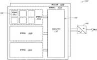
- FIG. 1illustrates an example system configured to shut down or start up a photovoltaic module, according to some embodiments.
- FIG. 2illustrates example circuitry configured to shut down or start up photovoltaic modules, according to some embodiments.
- FIG. 3is a flowchart illustrating an example method of performing shut down or start up of a photovoltaic module, according to some embodiments.
- FIG. 4is a block diagram of an example computer system configured to implement one or more of the disclosed techniques, according to some embodiments.
- FIG. 5illustrates an example diagram of circuitry configured to disable a PV module or string by opening one or more switches in series, according to some embodiments.
- first“First,” “Second,” etc. As used herein, these terms are used as labels for nouns that they precede, and do not imply any type of ordering (e.g., spatial, temporal, logical, etc.). For example, reference to a “first” state of operation of a PV module does not necessarily imply that this state is the first state in a sequence; instead the term “first” is used to differentiate this state from another state (e.g., a “second” state).
- this termis used to describe one or more factors that affect a determination. This term does not foreclose additional factors that may affect a determination. That is, a determination may be solely based on those factors or based, at least in part, on those factors.
- a determinationmay be solely based on those factors or based, at least in part, on those factors.
- Coupledmeans that one element/node/feature is directly or indirectly joined to (or directly or indirectly communicates with) another element/node/feature, and not necessarily mechanically.
- inhibitis used to describe a reducing or minimizing effect. When a component or feature is described as inhibiting an action, motion, or condition it may completely prevent the result or outcome or future state completely. Additionally, “inhibit” can also refer to a reduction or lessening of the outcome, performance, and/or effect which might otherwise occur. Accordingly, when a component, element, or feature is referred to as inhibiting a result or state, it need not completely prevent or eliminate the result or state.
- This specificationfirst describes structures for shutting down and starting up PV modules followed by an example method for performing shut down and start up. Various examples are provided throughout.
- PV system 190includes a plurality of PV modules, such as PV modules 100 a and 100 b .
- Each PV modulecan be subdivided into several groupings of solar cells, referred to as cell strings, such as strings 102 a , 102 b , and 102 c .
- Cell stringscan include a plurality of series-connected solar cells, for example, 10-40 individual series-connected solar cells (e.g., solar cell 104 ).
- the number of solar cells in a string, and the number of strings in a PV moduledetermines the voltage produced by the string and PV module, respectively.
- the example PV module of FIG. 1illustrates three strings of solar cells, in other embodiments, a different number of strings can be coupled in series in a PV module.
- the PV moduleincludes or is otherwise associated with circuitry 110 .
- circuitry 110can be configured to receive an indication, such as indication 142 , of the status of the PV system and can also be configured to determine (e.g., based on the indication) whether to switch between an enabled state in which the PV module's output voltage and power includes voltage and power from all of the plurality of solar cells (e.g., each string) and a disabled state in which the PV module is disabled.
- a PV modulecan be considered disabled when it outputs substantially no DC power or voltage thereby bypassing the strings from substantially providing voltage to the PV module's output voltage, and vice versa.
- a PV module operating in the disabled statecan be referred to as a disabled or shut down PV module.
- Placing the PV module in the disabled stateis referred to herein as shutting down or disabling the PV module.
- a PV module operating in the enabled stateis referred to herein as an active PV module and placing the PV module in the enabled state from the disabled state is referred to herein as starting up the PV module.
- indication 142 of the status of the PV systemcan be received by circuitry 110 from a number of different sources.
- indication 142can be provided by an inverter, such as inverter 140 , from a sensor within PV module 100 a and/or circuitry 110 , or from some other component outside of PV module 100 a .
- the indicationcan be a shutdown indication, a heartbeat indication, a startup indication, a time-varying light indication, a vibration indication, a parameter measured by the circuitry or other component, among other examples.
- circuitry 110can be configured to disable the PV module by opening one or more switches in series with one or more of the PV module's output connections or cell string connections hereby disconnecting the module's cells from the rest of the array and/or by closing one or more switches (shorting) in parallel with the module or sections of the module thereby reducing the voltage to a small level while leaving the panel connected to the load.
- PV 1 -PV 4represent connections to a module's cell-strings.
- a series FET or other switchcan be opened by controller 130 to disable at the cell string connection indicated by PV 1 and PV 4 .
- a switchcan be located at the negative line of the cell string connection (top portion of FIG. 5 ) or at the positive line of the cell string connection (bottom portion of FIG. 5 ).
- FIG. 5only illustrates a single switch configuration, in some embodiments, more than one switch can be used.
- circuitry 110can be a voltage limiting device and, in one embodiment, can include a parallel current path provided across each cell string such that the output of the respective cell string can be included or excluded from the output of the PV module, for example, based on the configuration of one or more switches.
- the parallel current pathcan be configured to lower the total impedance on the cell string's output, which can lower the generated voltage of the PV module.
- the parallel current pathcan be provided across the entire PV module, a plurality of cells, a plurality of strings, or plurality of modules, to achieve a similar effect.
- the parallel current pathcan be provided across the entire PV module.
- Circuitry 110can be located at or in the PV module in a number of ways.
- circuitry 110can be in an enclosure (e.g., junction box or other enclosure) attached and wired to the module, in a removable electronics module where the PV module's connections are protected from inadvertent contact when the electronics module is not present, or installed in the module, for instance, as part of the lamination process.
- the components of circuitry 110 described hereincan be distributed. For example, some components can reside in the junction box and others can reside remote from the module.
- circuitry 110instead of circuitry 110 being located in a junction box, one or more components of the overvoltage protection device can be located in other locations, such as in the encapsulation of the PV module, or external to the PV module.
- the output of the PV modulescan be coupled to inverter 140 , which can be configured to convert the direct current (DC) output from the PV modules to alternating current (AC) to provide to the grid.
- inverter 140can be configured to convert the direct current (DC) output from the PV modules to alternating current (AC) to provide to the grid.
- circuitry 110can includes one or more switches, such as switches 112 a , 112 b , and 112 c . Although the illustrated circuitry includes three switches, one switch per string of solar cells, in other examples, a single switch can be used per PV module.
- a parallel current pathcan be implemented, using a switch or switches, such as relays, field effect transistors (FETs), bipolar junction transistors (BJT), insulated-gate bipolar transistors (IGBT), micro electro mechanical system (MEMS) relay, or other switching mechanisms that can be switched between a low-resistance state and a high-resistance state.
- the solar cells of a modulecan be shorted (e.g., bypassed) by closing the switch or switches (e.g., switch 112 a , 112 b , and 112 c ) across the PV module to enable the parallel current path.
- Switchesare illustrated in FIG. 2 as FETs 112 a , 112 b , and 112 c .
- a different number of switchese.g., one
- a different number of switchese.g., one
- a different number of switchese.g., one
- a different number of switchese.g., one) other
- circuitry 110can include an analog or digital controller 130 configured to provide an indication to driver 120 or drivers, such as drivers 120 a , 120 b , and 120 c (as illustrated), which can be configured to turn on (e.g., enable, engage, close, activate) the switch(es) to short a cell string or entire module thereby reducing the voltage contribution from that cell string to approximately zero volts.
- driver 120can be circuitry (e.g., one or more transistors) configured to level shift the controller 130 output to command the switch to turn on or off.
- switchingis described as being performed on an entire cell string, in some embodiments, switching can be performed at the module level, at the cell level, or in some combination of cell level, string level, and/or module level.
- the switches and controllercan be located on the same printed circuit board.
- the switches and controllercan be assembled on a rigid or flexible printed circuit board or other substrate, such as low-temperature co-fired ceramic, suitable for electrical connections and mechanical support of the components.
- Some components of the circuitrymay be mounted separately on conductors that are part of the PV module assembly such as bus bars or terminals, and may be electrically connected to the conductor and/or to other circuitry by soldering, welding, brazing, crimping, wire bonding, or a combination of those methods.
- controller 130(analog or digital) can be implemented using hardware, firmware, software, or some combination thereof.
- controller 130can include one or more of a microprocessor or microcontroller, program memory, data memory, associated logic, a programmable logic device, and/or non-programmable circuitry.
- the circuitrycan include a built-in test (BIT) facility that includes circuitry and/or program code that is configured to test the device, in whole or in part, for proper operation.
- the BIT facilitycan be configured to detect certain malfunctions and can cause the device to take action to limit the hazards or damage that may be caused by such malfunctions. Such actions can include disabling the module, or preventing the module from being disabled, permanently or until it can be repaired.
- circuitry 110can include a power supply, which can be configured to provide power to the components of circuitry 110 .
- the power supplycan be configured to convert part of the power available from the module, from part of the module, or from the module's connection to the PV array into a voltage and current suitable for operating circuitry 110 .
- the power supplycan operate even if the PV module does not produce sufficient power on its own, such as at night
- controller 130can be configured to receive indication 142 of the status of the PV system and determine whether to enable or disable the PV modules, for example by turning off the parallel path (e.g., opening, disabling, disengaging, deactivating) or engaging the parallel path to short the cells, respectively.
- the indication of the status of the PV systemcan be a variety of different indications.
- the indicationcan be a heartbeat or startup indication from inverter 140 as shown by indication 142 a .
- indication 142 bcan be measured by sensor 150 and can be provided to controller 130 .
- Examples of indication 142 binclude a vibration measurement, a voltage or current measurement, among other examples.
- indication 142 of the status of the PV systemcan be received by circuitry 110 from inverter 140 as indication 142 a , from sensor 150 within PV module 100 a or circuitry 110 , or from some other component outside of PV module 100 a .
- indication 142 bcan be measured by sensor 150 and provided to controller 130 .
- sensor 150can be configured to sense the PV module's and/or PV array's performance (e.g., voltage across the module, current through the module), vibration measurement, and/or temperature at one or more locations on the module or in the circuitry, among other examples. Note that such performance measurements can also be used for the BIT facility.
- indication 142 acan be received by controller 130 from a component outside of circuitry 110 , such as from inverter 140 or some other component.
- inverter 140can provide an indication that is an explicit shutdown command or a heartbeat indication, among other examples.
- controller 130can include a transceiver configured to receive data or a command from a component outside the PV module and/or to send information, such as measurements and/or identifying information (e.g., GPS data, RFID data), to the outside component.
- informationsuch as measurements and/or identifying information (e.g., GPS data, RFID data)
- data, command, or informationcan be sent through wired or wireless (e.g., ZigBee, mesh network, Wi-Fi, Bluetooth, etc.) communication.
- a central component common to multiple PV modulessuch as inverter 140 , can provide an indication to distributed controllers 130 , local to each PV module, to enable or disable the PV modules.
- local and central control of enabling and disabling the PV modulescan be used together such that a global enabling or disabling can be performed for a subset of the PV modules of an array due to some local condition (e.g., based on local measurements).
- controller 130can determine to disable the PV module or modules based on results of measurements of the module (e.g., current exceeding a particular level in a particular direction) or based on receiving a shutdown command from a remote device (e.g., inverter 140 ) or based on failing to receive a periodic command (e.g., heartbeat) to stay enabled. In various embodiments, controller 130 can determine to enable the PV module or modules based on receiving a command from a remote device to become enabled or based on measurements at the module(s).
- a remote devicecan periodically send an enable command, which can be a heartbeat indication, to some or all the modules in an array instructing them to remain enabled (or become enabled) for a period of time. Should a module not timely receive the heartbeat indication, its controller 130 can determine to disable the PV module and then disable the PV module (e.g., by enabling the parallel current path).
- the heartbeat transmittercan be powered by the AC grid, by the inverter's output, or by a separate power source.
- the heartbeat transmitteris powered by the inverter's output and the inverter correctly detects disconnection of the AC power grid, then disconnecting the AC power grid at a location remote from the inverter would cause the inverter to shut down, causing the heartbeat transmitter to lose power.
- the controller or controllers corresponding to the PV moduleswould fail to receive the heartbeat within the expected period of time to receive the heartbeat and then disable the modules. By doing so, the inverter and some or all modules feeding it can be disabled and stop producing a hazardous voltage without requiring any work to be done near the modules (i.e., service and/or emergency personnel do not have to approach the array to put it into a safe state).
- the heartbeat indicationcan be provided to the modules in a variety of ways.
- an electrical signalcan be imposed on the array, such as a time-varying current, which can be detected and discriminated from noise or other outside influences by sensing circuitry.
- power-line communicationPLC
- PLCpower-line communication
- PLCcan be used to transmit or receive a variation in the module's voltage or current between the remote device and module.
- PLCcan be used to send a heartbeat indication such that a periodic indication can be sent to multiple modules causing the multiple modules to remain enabled for a predetermined amount of time (e.g., 10 seconds, 15 seconds).
- the remote transmitting devicecan be the inverter, combiner box, or some other component, as described herein.
- the inverteris the device transmitting the heartbeat indication
- a specific heartbeat circuitcan be included in the inverter to provide the heartbeat or the heartbeat indication can be produced by altering the normal operation of the inverter circuitry.
- Examples of variations to the normal operation of the inverterinclude changing the timing and/or magnitude of maximum power-point tracking (MPPT) steps, causing the array's operating point (and its voltage or current) to vary according to a predetermined pattern (but in a way that has a small effect on the power produced by the inverter), or applying a voltage to the array, even if the array cannot produce usable power (e.g., before sunrise).
- MPPTmaximum power-point tracking
- a voltagecan be applied to the array by adjusting the timing of a three-phase bridge or by connecting a precharge circuit to the array to cause the array's voltage to increase while some or all the modules are disabled.
- one particular exampleis to change the frequency of the pulse width modulated signal driving the switches in the inverter's main power conversion stages. By varying these control signals in a unique pattern, the pattern can be transmitted as a change in the fairly high frequency noise coupled from the inverter throughout the modules of the array.
- a safety shutdown devicelocated in the field, can measure these current and/or voltage differences and reconstruct a shutdown, startup, or heartbeat signal, and take the appropriate action to enable/disable the array, the subset of the array, or the module under its control.
- circuitry 110can detect the normal operation of the inverter, including the current drawn during normal operation or small variations in the current due to MPPT or the inverter's tracking of the AC power grid frequency. Circuitry 110 can detect current with a current-sensing circuit or by inferring the current, or a change in current, from the voltage across the module or part of the module. Accordingly, circuitry 110 likewise can detect variations in the normal operation of the inverter in embodiments in which the heartbeat indication is a ripple or other variation to the normal operation.
- time-varying lightcan be applied to the module's cells causing a change in the voltage or current measured by sensing circuitry in the module such that the indication can be received in the form of the change in voltage or current.
- indication 142can be sent to all modules in the array, a subset of the modules, or to a single module.
- some combination of local and external controllerscan be used to engage and disengage the modules. For instance, determination of whether to enable or disable a module can be performed by a local controller based on an indication provided by a central controller.
- controllerscan coordinate with one another such that enabling or disabling is consistent in the array. For example, if a single local controller missed an indication to shut down, the other local controllers can share the shutdown signal with that single local controller to help ensure shutdown takes place. Note that such coordination need not take place for an entire array.
- system level coordinationcan refer to a system of PV modules coupled to some downstream hardware, such as an inverter, combiner box, etc.
- invertersare powered solely by the PV array and cannot send an enable indication to the modules before some or all of the modules become enabled.
- a separate startup circuitcan be used to send an enable indication to one or more modules in the array to become enabled so that the inverter can begin operating.
- the startup circuitcan be built into the inverter enclosure but can be separate from the inverter's power production circuitry.
- the startup circuitcan use the AC power grid connection at the inverter's output as a power source.
- the startup circuitcan send the initial startup indication and the heartbeat indication during normal operation, or it just can send the startup indication before the inverter's normal operations.
- the sequencecan be as follows.
- the invertercan be unpowered and the modules disabled, but the startup circuit itself can be powered.
- the startup circuitcan send a startup indication, which can be the same as or different than the heartbeat indication.
- the PV modules and respective circuitry 110can receive and detect the heartbeat indication.
- circuitry 110can determine to enable and enable the PV modules.
- the invertercan begin normal operation and commence sending the period heartbeat indication to the various circuitry 110 and the startup circuitry can stop sending the startup indication.
- Circuitry 110can then detect the inverter's heartbeat indication and/or detect its absence after a period of time and make a determination whether to enable or disable its associated PV module(s) or keep them in the current enabled or disabled state.
- circuitry 110can lose power when the module is insufficiently illuminated unless its power supply obtains power from a source other than the PV module, such as the AC grid. Circuitry 110 can turn on around sunrise and turn off around sunset so the module is in a well-defined state when circuitry 110 is first powered each day. Circuitry 110 can reset due to loss of power if external influences, such as array current, cause the power supply to be unable to operate due to the voltage across the PV module. When a load is connected to the array, such as when a DC disconnect switch on the inverter is closed, a large current can flow from the PV modules, which can cause circuitry 110 on one or more modules to reset.
- a loadis connected to the array, such as when a DC disconnect switch on the inverter is closed, a large current can flow from the PV modules, which can cause circuitry 110 on one or more modules to reset.
- the PV modulecan repeatedly reset while, for example, input capacitors on the inverter charge.
- Circuitry 110can detect such a condition through measurements (e.g., 142 b ) of the module or by measuring the time that the power supply was unable to operate, and can modify its behavior while the condition persists. During normal operation, circuitry 110 can remain powered and the module would remain enabled.
- FIG. 3a flow chart illustrating a method for enabling or disabling PV modules is shown, according to some embodiments.
- the method of FIG. 3may include additional (or fewer) blocks than illustrated.
- an indication of a status of a PV module or modulescan be received by circuitry associated with the PV module(s), such as circuitry 110 .
- the indicationcan be a shutdown indication/command, a periodic heartbeat indication, a startup indication, an indication of a measurement at or near the module (e.g., voltage, current, temperature, vibration), among other examples.
- the indicationcan be received from a local source, such as from a sensor at the PV module, or from a remote source, such as from an inverter, combiner box, or some other component (e.g., a manual “stop” button).
- the indicationcan be received by the circuitry over the power line (e.g., PLC), wirelessly (e.g., ZigBee, mesh network), or otherwise.
- the power linee.g., PLC
- wirelesslye.g., ZigBee, mesh network
- Circuitrycan be shared among multiple PV modules or can be distributed such that each PV module is associated with corresponding circuitry.
- One example of the distributed circuitrycan be in the form of a voltage limiting device in an enclosure (e.g., junction box) coupled mechanically to the back of the PV module or within the laminate of the PV module.
- whether to switch between a first state and a second statecan be determined based on the received indication.
- a controller of the circuitrycan either directly, or through one or more drivers, enable or disable the switch(es) to disable or enable the PV module, respectively.
- the parallel pathcan be enabled such that the solar cells corresponding to the enabled switch(es) are no longer contributing voltage to the PV module's output.
- the circuitrycan determine to disable the PV module.
- the circuitrycan determine to keep operating the PV in the enabled state. Furthering the heartbeat example, the circuitry can similarly determine at 304 that no heartbeat indication has been received for a threshold amount of time, and determine to disable the PV module.
- a timercan be received by circuitry 110 and it can reset each time the heartbeat indication is received. If the timer reaches the threshold amount (e.g., 5 seconds, 10 seconds, 20 seconds), then circuitry can determine to disable the PV module.
- the indicationis a startup indication
- the circuitrycan determine at 304 to enable the PV module based on receiving the startup indication.
- the heartbeat indicationcan be provided in a variety of manners.
- a componentsuch as an inverter
- the invertercan provide the heartbeat indication to the circuitry by applying a voltage based on a modified modulation scheme to the PV modules.
- the invertercan produce ripples in the current that are detectable by circuitry 110 . The ripples could be produced in a complicated pattern that is unlikely to naturally occur and therefore be easy for circuitry 110 to identify as a heartbeat indication.
- the invertercan provide the heartbeat indication as a pseudo random digital code.
- the heartbeatcan be provided multiple times within the threshold time period to help ensure that the circuitry can receive the heartbeat within the threshold time period even if one of the heartbeats is not properly received by the circuitry.
- the heartbeat indicationcan be provided 2-3 times within a 10 second period.
- the magnitude of MPPT steps for MPPT trackingcan be modified.
- the invertercan adjust the amount of power it is drawing by changing the string current (and voltage) up or down in small steps every few seconds.
- a more complicated and recognizable pattern of MPPT step changingcan be used (e.g., go up for 1 second, down for 2 seconds, etc.) such that circuitry can detect that the MPPT pattern is indicative of normal operation of the inverter and therefore the circuitry can determine to keep the PV module enabled.
- the disclosed structures and techniquescan provide for safety shutdown and/or startup in a safe and orderly manner to help facilitate installation, maintenance, and emergency work at or nearby an array while inhibiting downtime and unnecessary shutting down of the array.
- Circuitry 400configured to implement one or more portions of the disclosed techniques is shown.
- Circuitry 400can be any suitable device, including, but not limited to module-level electronics, etc.
- circuitry 400can include processor unit 450 , memory 420 , input/output (I/O) interface 430 coupled via an interconnect 460 (e.g., a system bus).
- I/O interface 430can be coupled to one or more I/O devices 440 .
- processor unit 450can include one or more processors. In some embodiments, processor unit 450 can include one or more coprocessor units. In some embodiments, multiple instances of processor unit 450 can be coupled to interconnect 460 . Processor unit 450 (or each processor within 450 ) can contain a cache or other form of on-board memory. In general circuitry 400 is not limited to any particular type of processor unit or processor subsystem.
- Memory 420can be usable by processor unit 450 (e.g., to store instructions executable by and data used by unit 450 ).
- Memory 420may be implemented by any suitable type of physical memory media, including hard disk storage, floppy disk storage, removable disk storage, flash memory, random access memory (RAM—SRAM, EDO RAM, SDRAM, DDR SDRAM, Rambus® RAM, etc.), ROM (PROM, EEPROM, etc.), and so on.
- ROMPROM, EEPROM, etc.
- Memory 420may consist solely of volatile memory in one embodiment.
- Memory in circuitry 400is not necessarily limited to memory 420 . Rather, circuitry 400 may be said to have a “memory subsystem” that includes various types/locations of memory.
- the memory subsystem of circuitry 400may, in one embodiment, include memory 420 , cache memory in processor unit 450 , storage on I/O devices 440 (e.g., a hard drive, storage array, etc.), and so on. Accordingly, the phrase “memory subsystem” is representative of various types of possible memory media within circuitry 400 .
- the memory subsystem of computer 400may store program instructions executable by processor unit 450 , including program instructions executable to implement the various techniques disclosed herein.
- I/O interface 430may represent one or more interfaces and may be any of various types of interfaces configured to couple to and communicate with other devices (e.g., to receive an indication of the status of the PV system from an inverter, to communicate module status to an inverter or other remote device), according to various embodiments.
- I/O interface 430is a bridge chip from a front-side to one or more back-side buses. I/O interface 430 may be coupled to one or more I/O devices 440 via one or more corresponding buses or other interfaces.
- I/O devicesexamples include storage devices (hard disk (e.g., 440 E), optical drive, removable flash drive, storage array, SAN, or an associated controller), network interface devices (e.g., 440 A, which may couple to a local or wide-area network), user interface devices (e.g., mouse 440 B, keyboard 440 C, display monitor 440 D) or other devices (e.g., graphics, sound, etc.).
- circuitry 400can be coupled to a network 470 via a network interface device 440 A.
- I/O devices 440are not limited to the examples listed above. All depicted I/O devices 440 need not be present in all embodiments of circuitry 400 .
- Circuitry 400may be used to implement the various techniques described herein.
- Articles of manufacture that store instructions (and, optionally, data) executable by a computer system to implement various techniques disclosed hereinare also contemplated. These articles of manufacture include tangible computer-readable memory media.
- the contemplated tangible computer-readable memory mediainclude portions of the memory subsystem of circuitry 400 (without limitation SDRAM, DDR SDRAM, RDRAM, SRAM, flash memory, and various types of ROM, etc.), as well as storage media or memory media such as magnetic (e.g., disk) or optical media (e.g., CD, DVD, and related technologies, etc.).
- the tangible computer-readable memory mediamay be either volatile or nonvolatile memory.
- the processor unitcan include one or more processors or cores.
- the processor unitcan contain a cache or other form of on-board memory.
- the memoryis usable by the processor unit (e.g., to store instructions executable by and data used by the processor unit).
- the memorycan be implemented by any suitable type of physical memory media, including hard disk storage, floppy disk storage, removable disk storage, flash memory, random access memory (RAM—SRAM, EDO RAM, SDRAM, DDR SDRAM, Rambus® RAM, etc.), ROM (PROM, EEPROM, etc.), and so on.
- the memorycan consist solely of volatile memory in one embodiment.
Landscapes
- Inverter Devices (AREA)
- Charge And Discharge Circuits For Batteries Or The Like (AREA)
- Photovoltaic Devices (AREA)
Abstract
Description
Claims (11)
Priority Applications (8)
| Application Number | Priority Date | Filing Date | Title |
|---|---|---|---|
| US14/748,038US10992255B2 (en) | 2014-10-28 | 2015-06-23 | Photovoltaic module or array shutdown |
| EP15854484.1AEP3213408B1 (en) | 2014-10-28 | 2015-10-21 | Photovoltaic module or array shutdown |
| PCT/US2015/056776WO2016069351A1 (en) | 2014-10-28 | 2015-10-21 | Photovoltaic module or array shutdown |
| CN201580050514.0ACN107078691B (en) | 2014-10-28 | 2015-10-21 | Photovoltaic system, method of operating a photovoltaic system and voltage limiting device |
| US17/223,953US11437953B2 (en) | 2014-10-28 | 2021-04-06 | Photovoltaic module or array shutdown |
| US17/875,892US12074565B2 (en) | 2014-10-28 | 2022-07-28 | Photovoltaic module or array shutdown |
| US18/453,241US12308792B2 (en) | 2014-10-28 | 2023-08-21 | Photovoltaic module or array shutdown |
| US19/189,516US20250253806A1 (en) | 2014-10-28 | 2025-04-25 | Photovoltaic Module or Array Shutdown |
Applications Claiming Priority (2)
| Application Number | Priority Date | Filing Date | Title |
|---|---|---|---|
| US201462069784P | 2014-10-28 | 2014-10-28 | |
| US14/748,038US10992255B2 (en) | 2014-10-28 | 2015-06-23 | Photovoltaic module or array shutdown |
Related Child Applications (1)
| Application Number | Title | Priority Date | Filing Date |
|---|---|---|---|
| US17/223,953ContinuationUS11437953B2 (en) | 2014-10-28 | 2021-04-06 | Photovoltaic module or array shutdown |
Publications (2)
| Publication Number | Publication Date |
|---|---|
| US20160118934A1 US20160118934A1 (en) | 2016-04-28 |
| US10992255B2true US10992255B2 (en) | 2021-04-27 |
Family
ID=55792801
Family Applications (5)
| Application Number | Title | Priority Date | Filing Date |
|---|---|---|---|
| US14/748,038Active2036-09-03US10992255B2 (en) | 2014-10-28 | 2015-06-23 | Photovoltaic module or array shutdown |
| US17/223,953ActiveUS11437953B2 (en) | 2014-10-28 | 2021-04-06 | Photovoltaic module or array shutdown |
| US17/875,892ActiveUS12074565B2 (en) | 2014-10-28 | 2022-07-28 | Photovoltaic module or array shutdown |
| US18/453,241ActiveUS12308792B2 (en) | 2014-10-28 | 2023-08-21 | Photovoltaic module or array shutdown |
| US19/189,516PendingUS20250253806A1 (en) | 2014-10-28 | 2025-04-25 | Photovoltaic Module or Array Shutdown |
Family Applications After (4)
| Application Number | Title | Priority Date | Filing Date |
|---|---|---|---|
| US17/223,953ActiveUS11437953B2 (en) | 2014-10-28 | 2021-04-06 | Photovoltaic module or array shutdown |
| US17/875,892ActiveUS12074565B2 (en) | 2014-10-28 | 2022-07-28 | Photovoltaic module or array shutdown |
| US18/453,241ActiveUS12308792B2 (en) | 2014-10-28 | 2023-08-21 | Photovoltaic module or array shutdown |
| US19/189,516PendingUS20250253806A1 (en) | 2014-10-28 | 2025-04-25 | Photovoltaic Module or Array Shutdown |
Country Status (4)
| Country | Link |
|---|---|
| US (5) | US10992255B2 (en) |
| EP (1) | EP3213408B1 (en) |
| CN (1) | CN107078691B (en) |
| WO (1) | WO2016069351A1 (en) |
Cited By (2)
| Publication number | Priority date | Publication date | Assignee | Title |
|---|---|---|---|---|
| DE102023123913A1 (en)* | 2023-09-05 | 2025-03-06 | Hanwha Q Cells Gmbh | Rapid Shutdown System and Solar Module System |
| WO2025104357A1 (en)* | 2023-11-13 | 2025-05-22 | Energías Renovables Erín, S.L. | Device for controlling voltage and disconnecting photovoltaic modules for string |
Families Citing this family (21)
| Publication number | Priority date | Publication date | Assignee | Title |
|---|---|---|---|---|
| US10218182B2 (en) | 2016-09-22 | 2019-02-26 | Sunpower Corporation | Photovoltaic systems with voltage limiting devices |
| US10439554B2 (en)* | 2017-06-08 | 2019-10-08 | Jeff Kotowski | Method and apparatus for solar panel protection and control system |
| US10396593B1 (en) | 2017-07-05 | 2019-08-27 | Sunpower Corporation | Rapid shutdown of photovoltaic systems |
| CN109698493A (en)* | 2017-10-20 | 2019-04-30 | 浙江昱能科技有限公司 | A kind of method and system of safeguard protection photovoltaic system |
| CN108427356A (en)* | 2018-06-04 | 2018-08-21 | 天合光能股份有限公司 | Intelligent photovoltaic data acquisition system of photovoltaic module and inverter |
| CN111565020A (en) | 2019-02-14 | 2020-08-21 | 阳光电源股份有限公司 | Component voltage limiting method and application device and system thereof |
| US12291982B2 (en) | 2020-11-30 | 2025-05-06 | Rondo Energy, Inc. | Thermal energy storage systems for use in material processing |
| JP2021002930A (en)* | 2019-06-21 | 2021-01-07 | パナソニックIpマネジメント株式会社 | Shutdown system, shutdown method, and program |
| WO2021003728A1 (en)* | 2019-07-11 | 2021-01-14 | 华为技术有限公司 | Converter, method and system applied to photovoltaic power generation system |
| WO2021035571A1 (en)* | 2019-08-28 | 2021-03-04 | 华为技术有限公司 | Inverter of photovoltaic grid-connected power generation system, starting device and method, and system |
| CN111262767B (en)* | 2020-03-27 | 2022-11-15 | 阳光电源股份有限公司 | Photovoltaic system and communication method thereof |
| EP4509205A3 (en) | 2020-11-30 | 2025-04-23 | Rondo Energy, Inc. | Energy storage system and applications |
| US11913361B2 (en) | 2020-11-30 | 2024-02-27 | Rondo Energy, Inc. | Energy storage system and alumina calcination applications |
| US12359591B1 (en) | 2020-11-30 | 2025-07-15 | Rondo Energy, Inc. | Thermal energy storage systems for repowering existing power plants for improving efficiency and safety |
| US11913362B2 (en) | 2020-11-30 | 2024-02-27 | Rondo Energy, Inc. | Thermal energy storage system coupled with steam cracking system |
| US12018596B2 (en) | 2020-11-30 | 2024-06-25 | Rondo Energy, Inc. | Thermal energy storage system coupled with thermal power cycle systems |
| US12146424B2 (en) | 2020-11-30 | 2024-11-19 | Rondo Energy, Inc. | Thermal energy storage system coupled with a solid oxide electrolysis system |
| CN115347667A (en)* | 2021-05-13 | 2022-11-15 | 台达电子企业管理(上海)有限公司 | Photovoltaic inverter system and RSD automatic positioning method and fault control method thereof |
| IL309370B2 (en)* | 2021-06-16 | 2025-07-01 | Conti Spe Llc | Mechanically stacked solar cells or light-transmitting modules |
| FR3147856B3 (en) | 2023-04-14 | 2025-05-23 | Rondo Energy Inc | THERMAL ENERGY STORAGE BLOCKS AND ASSOCIATED SUPPORT STRUCTURES |
| US12414402B1 (en) | 2025-01-03 | 2025-09-09 | Conti Innovation Center, Llc | Optimizing cadmium (CD) alloy solar cells with sputtered copper-dopped zinc telluride (ZNTE:CU) back contacts in the presence of hydrogen |
Citations (22)
| Publication number | Priority date | Publication date | Assignee | Title |
|---|---|---|---|---|
| US6093885A (en)* | 1998-03-03 | 2000-07-25 | Canon Kabushiki Kaisha | Photovoltaic power generating system |
| US20020014262A1 (en)* | 2000-07-10 | 2002-02-07 | Masaaki Matsushita | Photovoltaic power generation systems and methods of controlling photovoltaic power generation systems |
| US20090121549A1 (en)* | 2007-11-14 | 2009-05-14 | General Electric Company | Method and system to convert direct current (dc) to alternating current (ac) using a photovoltaic inverter |
| WO2010078303A2 (en) | 2008-12-29 | 2010-07-08 | Atonometrics, Inc. | Electrical safety shutoff system and devices for photovoltaic modules |
| US20110088741A1 (en) | 2009-10-19 | 2011-04-21 | Randy Richard Dunton | Solar Photovoltaic Module Safety Shutdown System |
| US20110204900A1 (en)* | 2010-02-24 | 2011-08-25 | Bernhard Beck | Method and device for detecting underperforming pv modules in a pv system by using disconnect switches |
| US20110273302A1 (en)* | 2010-04-16 | 2011-11-10 | Enphase Energy, Inc. | Method and apparatus for indicating a disconnection within a distributed generator |
| US20120025621A1 (en) | 2008-08-10 | 2012-02-02 | Eric Seymour | Device, system, and method for sectioning and coupling multiple photovoltaic strings |
| US20120048325A1 (en)* | 2010-08-24 | 2012-03-01 | Sanyo Electric Co., Ltd. | Photovoltaic power generating device, and controlling method |
| US20120158200A1 (en) | 2010-12-17 | 2012-06-21 | Greenvolts, Inc | Integrated performance monitoring for a concentrated photovoltaic (cpv) system |
| US20120326511A1 (en) | 2011-06-27 | 2012-12-27 | Lars Johnson | Methods and apparatus for controlling operation of photovoltaic power plants |
| US20130058140A1 (en)* | 2010-05-03 | 2013-03-07 | Sma Solar Technology Ag | Method for limiting the generator voltage of a photovoltaic installation in case of danger and photovoltaic installation |
| US20130113293A1 (en)* | 2011-11-03 | 2013-05-09 | Array Power Inc. | Direct Current to Alternating Current Conversion Utilizing Intermediate Phase Modulation |
| US20130175971A1 (en)* | 2012-01-11 | 2013-07-11 | Solaredge Technologies Ltd. | Photovoltaic Module |
| US20130200710A1 (en)* | 2012-02-04 | 2013-08-08 | Steven Andrew Robbins | Solar Power Module with Safety Features and Related Method of Operation |
| US8624436B2 (en)* | 2009-06-09 | 2014-01-07 | Andre Poskatcheev Willis | Power harvesting circuit and method for serially coupled DC power sources |
| US20140121849A1 (en)* | 2012-10-25 | 2014-05-01 | New Jersey Institute Of Technology | Alleviating solar energy congestion in the distribution grid via smart metering communications |
| US20140168835A1 (en)* | 2012-12-18 | 2014-06-19 | Enphase Energy, Inc. | Smart junction box for a photovoltaic system |
| WO2014169292A2 (en) | 2013-04-13 | 2014-10-16 | Solexel, Inc. | Solar photovoltaic module power control and status monitoring system utilizing laminate-embedded remote access module switch |
| US20160079752A1 (en)* | 2014-07-04 | 2016-03-17 | Stefan Matan | Hierarchical and distributed power grid control |
| US9680301B2 (en)* | 2011-10-27 | 2017-06-13 | Sunpower Corporation | Master-slave architecture for controlling operation of photovoltaic power plants |
| US9742194B2 (en)* | 2015-05-08 | 2017-08-22 | Solantro Semiconductor Corp. | Photovoltaic power system inverter detection |
Family Cites Families (30)
| Publication number | Priority date | Publication date | Assignee | Title |
|---|---|---|---|---|
| CH584948A5 (en) | 1973-11-16 | 1977-02-15 | Tvi Television Ind Sa | |
| US4873480A (en) | 1988-08-03 | 1989-10-10 | Lafferty Donald L | Coupling network for improving conversion efficiency of photovoltaic power source |
| US5054023A (en) | 1989-05-12 | 1991-10-01 | Kronberg James W | "Smart" watchdog safety switch |
| US5406249A (en) | 1993-03-09 | 1995-04-11 | Metricom, Inc. | Method and structure for coupling power-line carrier current signals using common-mode coupling |
| JP3775053B2 (en) | 1998-05-12 | 2006-05-17 | 富士電機機器制御株式会社 | Inverter device |
| JP2002252986A (en) | 2001-02-26 | 2002-09-06 | Canon Inc | Inverter, power supply system and method of reducing leakage current in power supply system |
| SE0302453D0 (en) | 2003-09-16 | 2003-09-16 | Solarit Ab | A module, a converter, a node, and a system |
| EP2306634A3 (en) | 2005-06-30 | 2015-04-29 | Continental Automotive Systems US, Inc. | Control system for electric drives |
| FR2894401B1 (en) | 2005-12-07 | 2008-01-18 | Transenergie Sa | DEVICE FOR CONTROLLING AN ELECTRIC POWER GENERATION PLANT AND ELECTRIC POWER GENERATING PLANT USING SUCH A DEVICE |
| US9088178B2 (en) | 2006-12-06 | 2015-07-21 | Solaredge Technologies Ltd | Distributed power harvesting systems using DC power sources |
| US8816535B2 (en) | 2007-10-10 | 2014-08-26 | Solaredge Technologies, Ltd. | System and method for protection during inverter shutdown in distributed power installations |
| US8013472B2 (en) | 2006-12-06 | 2011-09-06 | Solaredge, Ltd. | Method for distributed power harvesting using DC power sources |
| WO2008077473A2 (en) | 2006-12-21 | 2008-07-03 | Sp Solarprojekt Gmbh | Solar power generation plant |
| JP2008205678A (en) | 2007-02-19 | 2008-09-04 | Sharp Corp | Power line communication device |
| US7772716B2 (en) | 2007-03-27 | 2010-08-10 | Newdoll Enterprises Llc | Distributed maximum power point tracking system, structure and process |
| US20090000654A1 (en) | 2007-05-17 | 2009-01-01 | Larankelo, Inc. | Distributed inverter and intelligent gateway |
| WO2008156782A2 (en) | 2007-06-19 | 2008-12-24 | Sand Holdings, Llc | Devices and methods for automatic reset of monitored network network equipment |
| US7768751B2 (en) | 2008-01-29 | 2010-08-03 | Advanced Energy Industries, Inc. | System and method for ground fault detection and interruption |
| WO2009032931A2 (en) | 2007-09-04 | 2009-03-12 | Ticketmaster, Llc | Methods and systems for reservation and brokering of tickets or resources |
| US7755916B2 (en) | 2007-10-11 | 2010-07-13 | Solarbridge Technologies, Inc. | Methods for minimizing double-frequency ripple power in single-phase power conditioners |
| CN105244905B (en) | 2007-12-05 | 2019-05-21 | 太阳能安吉有限公司 | Release mechanism in distributed power device is waken up and method for closing |
| DE102008003272A1 (en)* | 2008-01-05 | 2009-07-09 | Hans-Hermann Hunfeld | Monitoring unit for photovoltaic modules |
| US9225285B2 (en) | 2008-09-24 | 2015-12-29 | Sunpower Corporation | Photovoltaic installation with automatic disconnect device |
| EP2290834A1 (en) | 2009-08-25 | 2011-03-02 | SMA Solar Technology AG | Closed-circuit power line communication |
| US8854193B2 (en) | 2009-12-29 | 2014-10-07 | Tigo Energy, Inc. | Systems and methods for remote or local shut-off of a photovoltaic system |
| GB2485527B (en) | 2010-11-09 | 2012-12-19 | Solaredge Technologies Ltd | Arc detection and prevention in a power generation system |
| GB2483317B (en) | 2011-01-12 | 2012-08-22 | Solaredge Technologies Ltd | Serially connected inverters |
| US8922062B2 (en) | 2011-03-14 | 2014-12-30 | Sunpower Corporation | Automatic voltage regulation for photovoltaic systems |
| US20130009483A1 (en) | 2011-05-31 | 2013-01-10 | Kawate Keith W | Power generator module connectivity control |
| DE102011053524B4 (en) | 2011-09-12 | 2015-05-28 | Sma Solar Technology Ag | Safety device for a photovoltaic system and method for operating a safety device for a photovoltaic system |
- 2015
- 2015-06-23USUS14/748,038patent/US10992255B2/enactiveActive
- 2015-10-21WOPCT/US2015/056776patent/WO2016069351A1/enactiveApplication Filing
- 2015-10-21EPEP15854484.1Apatent/EP3213408B1/enactiveActive
- 2015-10-21CNCN201580050514.0Apatent/CN107078691B/enactiveActive
- 2021
- 2021-04-06USUS17/223,953patent/US11437953B2/enactiveActive
- 2022
- 2022-07-28USUS17/875,892patent/US12074565B2/enactiveActive
- 2023
- 2023-08-21USUS18/453,241patent/US12308792B2/enactiveActive
- 2025
- 2025-04-25USUS19/189,516patent/US20250253806A1/enactivePending
Patent Citations (22)
| Publication number | Priority date | Publication date | Assignee | Title |
|---|---|---|---|---|
| US6093885A (en)* | 1998-03-03 | 2000-07-25 | Canon Kabushiki Kaisha | Photovoltaic power generating system |
| US20020014262A1 (en)* | 2000-07-10 | 2002-02-07 | Masaaki Matsushita | Photovoltaic power generation systems and methods of controlling photovoltaic power generation systems |
| US20090121549A1 (en)* | 2007-11-14 | 2009-05-14 | General Electric Company | Method and system to convert direct current (dc) to alternating current (ac) using a photovoltaic inverter |
| US20120025621A1 (en) | 2008-08-10 | 2012-02-02 | Eric Seymour | Device, system, and method for sectioning and coupling multiple photovoltaic strings |
| WO2010078303A2 (en) | 2008-12-29 | 2010-07-08 | Atonometrics, Inc. | Electrical safety shutoff system and devices for photovoltaic modules |
| US8624436B2 (en)* | 2009-06-09 | 2014-01-07 | Andre Poskatcheev Willis | Power harvesting circuit and method for serially coupled DC power sources |
| US20110088741A1 (en) | 2009-10-19 | 2011-04-21 | Randy Richard Dunton | Solar Photovoltaic Module Safety Shutdown System |
| US20110204900A1 (en)* | 2010-02-24 | 2011-08-25 | Bernhard Beck | Method and device for detecting underperforming pv modules in a pv system by using disconnect switches |
| US20110273302A1 (en)* | 2010-04-16 | 2011-11-10 | Enphase Energy, Inc. | Method and apparatus for indicating a disconnection within a distributed generator |
| US20130058140A1 (en)* | 2010-05-03 | 2013-03-07 | Sma Solar Technology Ag | Method for limiting the generator voltage of a photovoltaic installation in case of danger and photovoltaic installation |
| US20120048325A1 (en)* | 2010-08-24 | 2012-03-01 | Sanyo Electric Co., Ltd. | Photovoltaic power generating device, and controlling method |
| US20120158200A1 (en) | 2010-12-17 | 2012-06-21 | Greenvolts, Inc | Integrated performance monitoring for a concentrated photovoltaic (cpv) system |
| US20120326511A1 (en) | 2011-06-27 | 2012-12-27 | Lars Johnson | Methods and apparatus for controlling operation of photovoltaic power plants |
| US9680301B2 (en)* | 2011-10-27 | 2017-06-13 | Sunpower Corporation | Master-slave architecture for controlling operation of photovoltaic power plants |
| US20130113293A1 (en)* | 2011-11-03 | 2013-05-09 | Array Power Inc. | Direct Current to Alternating Current Conversion Utilizing Intermediate Phase Modulation |
| US20130175971A1 (en)* | 2012-01-11 | 2013-07-11 | Solaredge Technologies Ltd. | Photovoltaic Module |
| US20130200710A1 (en)* | 2012-02-04 | 2013-08-08 | Steven Andrew Robbins | Solar Power Module with Safety Features and Related Method of Operation |
| US20140121849A1 (en)* | 2012-10-25 | 2014-05-01 | New Jersey Institute Of Technology | Alleviating solar energy congestion in the distribution grid via smart metering communications |
| US20140168835A1 (en)* | 2012-12-18 | 2014-06-19 | Enphase Energy, Inc. | Smart junction box for a photovoltaic system |
| WO2014169292A2 (en) | 2013-04-13 | 2014-10-16 | Solexel, Inc. | Solar photovoltaic module power control and status monitoring system utilizing laminate-embedded remote access module switch |
| US20160079752A1 (en)* | 2014-07-04 | 2016-03-17 | Stefan Matan | Hierarchical and distributed power grid control |
| US9742194B2 (en)* | 2015-05-08 | 2017-08-22 | Solantro Semiconductor Corp. | Photovoltaic power system inverter detection |
Non-Patent Citations (8)
| Title |
|---|
| First Office Action for Chinese Patent Application No. 2015800505140 dated Sep. 11, 2018; 10 pgs—including English translation of the Office Action. |
| International Preliminary Report on Patentability for PCT Patent Application No. PCT/US15/56776 dated May 11, 2017, 10 pgs. |
| International Search Report and Written Opinion for PCT Patent Application No. PCT/US15/56776 dated Feb. 11, 2016, 13 pgs. |
| Official Communication from European Patent Application No. 15854484.1 dated Jun. 25, 2019, 4 pgs. |
| Official Communication from the EPO from European Patent Application No. 15854484.1, dated Feb. 26, 2018, 3 pgs. |
| Rejection Decision from Chinese Patent Application No. 201580050514.0 dated Oct. 21, 2019, 8 pgs. |
| Second Office Action from Chinese Patent Application No. 2015800505140 dated May 7, 2019, 8 pgs. |
| Third Office Action from Chinese Patent Application No. 2015800505140 dated Mar. 26, 2020, 4 pgs. |
Cited By (2)
| Publication number | Priority date | Publication date | Assignee | Title |
|---|---|---|---|---|
| DE102023123913A1 (en)* | 2023-09-05 | 2025-03-06 | Hanwha Q Cells Gmbh | Rapid Shutdown System and Solar Module System |
| WO2025104357A1 (en)* | 2023-11-13 | 2025-05-22 | Energías Renovables Erín, S.L. | Device for controlling voltage and disconnecting photovoltaic modules for string |
Also Published As
| Publication number | Publication date |
|---|---|
| US12074565B2 (en) | 2024-08-27 |
| WO2016069351A8 (en) | 2017-03-02 |
| US12308792B2 (en) | 2025-05-20 |
| EP3213408A4 (en) | 2017-09-06 |
| US20220368281A1 (en) | 2022-11-17 |
| US20240088829A1 (en) | 2024-03-14 |
| US20250253806A1 (en) | 2025-08-07 |
| US20210328544A1 (en) | 2021-10-21 |
| US11437953B2 (en) | 2022-09-06 |
| WO2016069351A1 (en) | 2016-05-06 |
| CN107078691A (en) | 2017-08-18 |
| CN107078691B (en) | 2020-10-02 |
| US20160118934A1 (en) | 2016-04-28 |
| EP3213408A1 (en) | 2017-09-06 |
| EP3213408B1 (en) | 2020-08-05 |
Similar Documents
| Publication | Publication Date | Title |
|---|---|---|
| US12074565B2 (en) | Photovoltaic module or array shutdown | |
| US10211631B2 (en) | Voltage clipping | |
| US10503126B2 (en) | Access control method for parallel direct current power supplies and device thereof | |
| JP2017144860A5 (en) | ||
| RU2013147635A (en) | HIGH VOLTAGE BATTERY SYSTEM FOR VEHICLE | |
| CN103703647A (en) | Power line communication device, solar power generation system, power line communication method, and power line communication program | |
| US9875860B2 (en) | Fiber optic ring for bypass system in multi-cell power supply | |
| EP2136411B1 (en) | Antitheft and monitoring system for photovoltaic panels | |
| US9893388B2 (en) | Method for activating a plurality of monitoring units for a battery, battery and motor vehicle having said battery | |
| WO2011086295A3 (en) | System for managing and controlling photovoltaic panels | |
| WO2012022345A3 (en) | Method for controlling individual photovoltaic modules in a photovoltaic installation, and control device | |
| CN106783392A (en) | The method for operating the contactor in the high-tension circuit of the vehicles | |
| US20130076318A1 (en) | Power supply control system and method | |
| CN109490771B (en) | A relay detection method and a relay detection device | |
| JP2016187240A (en) | Hot spot detection device | |
| US10661662B2 (en) | Battery charger for electric vehicles | |
| CN205336129U (en) | Main and secondary integrative deflector with redundancy protection function | |
| US9819187B2 (en) | Device for supplying power to HVDC converter | |
| CN107181235A (en) | Fault control for high-current pulse power supply | |
| JP2016187291A (en) | Power supply system and power conversion device | |
| TW200819332A (en) | Monitoring device and method of on-vehicle power | |
| CN102570378A (en) | Short-circuit protection circuit and method | |
| CN108429569A (en) | System and method for the DC electric power line communication in photovoltaic system | |
| CN203747414U (en) | System grid-connected inverter and displayer | |
| JP2016177350A (en) | Monitoring device, remote monitoring system, and monitoring program |
Legal Events
| Date | Code | Title | Description |
|---|---|---|---|
| AS | Assignment | Owner name:SUNPOWER CORPORATION, CALIFORNIA Free format text:ASSIGNMENT OF ASSIGNORS INTEREST;ASSIGNORS:JOHNSON, BENJAMIN ALEXANDER;PONCE, ANDREW JOSEPH;SIGNING DATES FROM 20151029 TO 20170130;REEL/FRAME:041156/0507 | |
| STPP | Information on status: patent application and granting procedure in general | Free format text:FINAL REJECTION MAILED | |
| STPP | Information on status: patent application and granting procedure in general | Free format text:DOCKETED NEW CASE - READY FOR EXAMINATION | |
| STPP | Information on status: patent application and granting procedure in general | Free format text:NON FINAL ACTION MAILED | |
| STPP | Information on status: patent application and granting procedure in general | Free format text:RESPONSE TO NON-FINAL OFFICE ACTION ENTERED AND FORWARDED TO EXAMINER | |
| STPP | Information on status: patent application and granting procedure in general | Free format text:FINAL REJECTION MAILED | |
| STPP | Information on status: patent application and granting procedure in general | Free format text:DOCKETED NEW CASE - READY FOR EXAMINATION | |
| STPP | Information on status: patent application and granting procedure in general | Free format text:NON FINAL ACTION MAILED | |
| STPP | Information on status: patent application and granting procedure in general | Free format text:FINAL REJECTION MAILED | |
| STPP | Information on status: patent application and granting procedure in general | Free format text:NON FINAL ACTION MAILED | |
| STPP | Information on status: patent application and granting procedure in general | Free format text:RESPONSE TO NON-FINAL OFFICE ACTION ENTERED AND FORWARDED TO EXAMINER | |
| STPP | Information on status: patent application and granting procedure in general | Free format text:NOTICE OF ALLOWANCE MAILED -- APPLICATION RECEIVED IN OFFICE OF PUBLICATIONS | |
| AS | Assignment | Owner name:SUNPOWER CORPORATION, CALIFORNIA Free format text:ASSIGNMENT OF ASSIGNORS INTEREST;ASSIGNORS:JOHNSON, BENJAMIN ALEXANDER;PONEC, ANDREW JOSEPH;SIGNING DATES FROM 20151029 TO 20170130;REEL/FRAME:055610/0693 | |
| STPP | Information on status: patent application and granting procedure in general | Free format text:PUBLICATIONS -- ISSUE FEE PAYMENT RECEIVED | |
| STPP | Information on status: patent application and granting procedure in general | Free format text:PUBLICATIONS -- ISSUE FEE PAYMENT VERIFIED | |
| STCF | Information on status: patent grant | Free format text:PATENTED CASE | |
| AS | Assignment | Owner name:BANK OF AMERICA, N.A., AS AGENT, NORTH CAROLINA Free format text:SECURITY INTEREST;ASSIGNOR:SUNPOWER CORPORATION;REEL/FRAME:061422/0566 Effective date:20220912 | |
| AS | Assignment | Owner name:SUNPOWER CORPORATION, CALIFORNIA Free format text:RELEASE OF SECURITY INTEREST IN CERTAIN PATENTS PREVIOUSLY RECORDED AT REEL/FRAME (061422/0566);ASSIGNOR:BANK OF AMERICA, N.A., AS AGENT;REEL/FRAME:064253/0920 Effective date:20230707 | |
| AS | Assignment | Owner name:SOLAREDGE TECHNOLOGIES LTD., ISRAEL Free format text:ASSIGNMENT OF ASSIGNORS INTEREST;ASSIGNOR:SUNPOWER CORPORATION;REEL/FRAME:064523/0270 Effective date:20230712 | |
| MAFP | Maintenance fee payment | Free format text:PAYMENT OF MAINTENANCE FEE, 4TH YEAR, LARGE ENTITY (ORIGINAL EVENT CODE: M1551); ENTITY STATUS OF PATENT OWNER: LARGE ENTITY Year of fee payment:4 |