US10992254B2 - Lead assembly for connecting solar panel arrays to inverter - Google Patents
Lead assembly for connecting solar panel arrays to inverterDownload PDFInfo
- Publication number
- US10992254B2 US10992254B2US14/849,458US201514849458AUS10992254B2US 10992254 B2US10992254 B2US 10992254B2US 201514849458 AUS201514849458 AUS 201514849458AUS 10992254 B2US10992254 B2US 10992254B2
- Authority
- US
- United States
- Prior art keywords
- aperture
- lead assembly
- feeder cable
- drop line
- undermold
- Prior art date
- Legal status (The legal status is an assumption and is not a legal conclusion. Google has not performed a legal analysis and makes no representation as to the accuracy of the status listed.)
- Active
Links
Images


Classifications
- H—ELECTRICITY
- H02—GENERATION; CONVERSION OR DISTRIBUTION OF ELECTRIC POWER
- H02S—GENERATION OF ELECTRIC POWER BY CONVERSION OF INFRARED RADIATION, VISIBLE LIGHT OR ULTRAVIOLET LIGHT, e.g. USING PHOTOVOLTAIC [PV] MODULES
- H02S40/00—Components or accessories in combination with PV modules, not provided for in groups H02S10/00 - H02S30/00
- H02S40/30—Electrical components
- H—ELECTRICITY
- H01—ELECTRIC ELEMENTS
- H01R—ELECTRICALLY-CONDUCTIVE CONNECTIONS; STRUCTURAL ASSOCIATIONS OF A PLURALITY OF MUTUALLY-INSULATED ELECTRICAL CONNECTING ELEMENTS; COUPLING DEVICES; CURRENT COLLECTORS
- H01R4/00—Electrically-conductive connections between two or more conductive members in direct contact, i.e. touching one another; Means for effecting or maintaining such contact; Electrically-conductive connections having two or more spaced connecting locations for conductors and using contact members penetrating insulation
- H01R4/70—Insulation of connections
- H—ELECTRICITY
- H01—ELECTRIC ELEMENTS
- H01R—ELECTRICALLY-CONDUCTIVE CONNECTIONS; STRUCTURAL ASSOCIATIONS OF A PLURALITY OF MUTUALLY-INSULATED ELECTRICAL CONNECTING ELEMENTS; COUPLING DEVICES; CURRENT COLLECTORS
- H01R9/00—Structural associations of a plurality of mutually-insulated electrical connecting elements, e.g. terminal strips or terminal blocks; Terminals or binding posts mounted upon a base or in a case; Bases therefor
- H01R9/03—Connectors arranged to contact a plurality of the conductors of a multiconductor cable, e.g. tapping connections
- H—ELECTRICITY
- H02—GENERATION; CONVERSION OR DISTRIBUTION OF ELECTRIC POWER
- H02G—INSTALLATION OF ELECTRIC CABLES OR LINES, OR OF COMBINED OPTICAL AND ELECTRIC CABLES OR LINES
- H02G15/00—Cable fittings
- H02G15/08—Cable junctions
- Y—GENERAL TAGGING OF NEW TECHNOLOGICAL DEVELOPMENTS; GENERAL TAGGING OF CROSS-SECTIONAL TECHNOLOGIES SPANNING OVER SEVERAL SECTIONS OF THE IPC; TECHNICAL SUBJECTS COVERED BY FORMER USPC CROSS-REFERENCE ART COLLECTIONS [XRACs] AND DIGESTS
- Y02—TECHNOLOGIES OR APPLICATIONS FOR MITIGATION OR ADAPTATION AGAINST CLIMATE CHANGE
- Y02E—REDUCTION OF GREENHOUSE GAS [GHG] EMISSIONS, RELATED TO ENERGY GENERATION, TRANSMISSION OR DISTRIBUTION
- Y02E10/00—Energy generation through renewable energy sources
- Y02E10/50—Photovoltaic [PV] energy
Definitions
- the present inventionrelates to electrical components, and more specifically to assemblies for connecting solar panel arrays to an inverter, without the need of a combiner box.
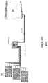
- a conventional solar power configurationincludes a plurality of solar panels 30 each connected to a central combiner box 36 , and a plurality of combiner boxes (not shown) connected to an inverter.
- the inverterconverts the direct current (DC) generated by the solar panels into alternating power (AC), which goes in the “grid”.
- FIG. 1The configuration of FIG. 1 has been simplified in recent years by the wire harness of U.S. Pat. No. 8,604,342 which issued Dec. 10, 2013; and U.S. application Ser. No. 14/057,089 filed Oct. 18, 2013; and Ser. No. 14/296,726 filed Jun. 5, 2014, all of which are hereby incorporated by reference. More specifically, as shown in FIG. 2 , wire harnesses 34 connect multiple solar panels 30 in an array 32 , so each array has a single input via wire harness 34 into the combiner box. This has drastically reduced the number of connections going into a combiner box, which is safer, more reliable, easier to install, maintain and troubleshoot, and saves money over the conventional configuration of FIG. 1 .
- a combiner boxis still a necessary component in known solar power installations because the energy coming from solar arrays must be combined prior to going into the inverter.
- Combiner boxesare problematic because they are clumsy, prone to damage and malfunctioning, must be periodically maintained, and require extensive planning and skill for installation. Due to the many connections going into a combiner box, a combiner box cannot easily be moved without disconnecting and reconnecting all the connections and wiring, which requires considerable manpower, danger, and expense.
- the present inventionis a lead assembly including at least one drop line joined to a feeder cable at a compression lug.
- the assemblyis preferably undermolded and overmolded where drop lines meet the feeder cable.
- the drop lineis connected to solar arrays, and the feeder cable is connected to an inverter, or to a buss trunk jumper, which connects to the inverter.
- a plurality of solar arraysare electrically coupled together, with a common feeder cable connecting them all to the inverter.
- a plurality of feeder cablescan be connected end to end, optionally terminating in a buss trunk jumper, for connection to an inverter.
- a combiner boxis not necessary, and in fact would be redundant.
- In line fusesmay be integrated into drop lines.
- each drop lineincludes a drop line connector for fast and easy connection to the wire harness that interconnects the solar panels of a solar array.
- a lead assemblypreferably includes one or two drop lines, depending on the particular configuration in a solar field.
- a lead assemblypreferably includes a capping end piece at one end of the feeder cable, and a feeder cable connector at the other end. The feeder cable connector would plug into an inverter, buss trunk jumper, or possibly another feeder cable.
- FIG. 1depicts a conventional wiring configuration with each solar panel individually wired to a central combiner box
- FIG. 2depicts an improved but known wiring configuration with solar panels harnessed together to form solar arrays, with each solar array individually wired to a central combiner box;
- FIG. 3depicts the present invention of a plurality of wire harnesses coupled to a lead assembly that connects to an inverter, with the unnecessary combiner box shown for demonstration only;
- FIG. 4schematically represents a system of the present invention
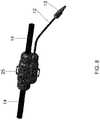
- FIG. 5depicts a positive lead assembly having a single drop line per joint
- FIG. 6depicts a negative lead assembly having a single drop line per joint
- FIG. 7schematically depicts a joint with a compression lug
- FIG. 8depicts a single drop joint
- FIG. 9depicts a configuration where a lead assembly has a single drop line as may be appropriate in use with crystalline panels
- FIG. 10depicts a configuration where a lead assembly has a single drop line as may be appropriate in use with thin film panels
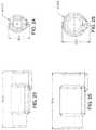
- FIGS. 11-12depict the overmold for a dual drop lead assembly for 250 mcm cable
- FIGS. 13-14depict the overmold for a dual drop lead assembly for 750 MCM cable
- FIGS. 15-16depict the undermold for a dual drop lead assembly for 250 MCM cable
- FIGS. 17-18depict the undermold for a dual drop lead assembly for 750 MCM cable
- FIGS. 19-20depict the overmold for a single drop lead assembly for 250 MCM cable
- FIGS. 21-22depict the overmold for a single drop lead assembly for 750 MCM cable
- FIGS. 23-24depict the undermold for a single drop lead assembly for 250 MCM cable
- FIGS. 25-26depict the undermold for a single drop lead assembly for 750 MCM cable
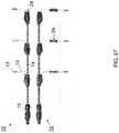
- FIG. 27depicts two lead assemblies with single drop, with the lower assembly including in line fuses
- FIG. 28depicts a spooled lead assembly with single drop
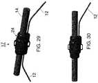
- FIG. 29depicts a dual drop lead assembly for 750 MCM cable
- FIG. 30depicts a single drop lead assembly for 750 MCM cable
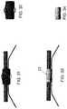
- FIG. 31depicts a dual drop lead assembly for 750 MCM cable with overmold shown
- FIG. 32depicts the overmold for a dual drop lead assembly for 750 MCM cable
- FIG. 33depicts a dual drop lead assembly for 750 MCM cable with undermold shown
- FIG. 34depicts the undermold for a dual drop lead assembly for 750 MCM cable
- FIG. 35depicts a dual drop lead assembly for 750 MCM cable with compression lug shown
- FIG. 36depicts the compression lug for a dual drop lead assembly for 750 MCM cable
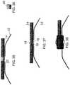
- FIG. 37depicts a dual drop lead assembly for 750 MCM cable with wires exposed at nexus
- FIG. 38depicts the end piece for a dual drop lead assembly for 750 MCM cable
- FIG. 39depicts a single drop lead assembly for 750 MCM cable with overmold shown
- FIG. 40depicts the overmold for a dual single lead assembly for 750 MCM cable
- FIG. 41depicts a single drop lead assembly for 750 MCM cable with undermold shown
- FIG. 42depicts the undermold for a single drop lead assembly for 750 MCM cable
- FIG. 43depicts a single drop lead assembly for 750 MCM cable with compression lug shown
- FIG. 44depicts the compression lug for a single drop lead assembly for 750 MCM cable
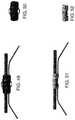
- FIG. 45depicts a single drop lead assembly for 750 MCM cable with wires exposed at nexus
- FIG. 46depicts the end piece for a single drop lead assembly for 750 MCM cable
- FIG. 47depicts a dual drop lead assembly for 250 MCM cable
- FIG. 48depicts a single drop lead assembly for 250 MCM cable with the overmold depicted in phantom;
- FIG. 49depicts a dual drop lead assembly for 250 MCM cable with overmold shown
- FIG. 50depicts the overmold for a dual drop lead assembly for 250 MCM cable
- FIG. 51depicts a dual drop lead assembly for 250 MCM cable with undermold shown
- FIG. 52depicts the undermold for a dual drop lead assembly for 250 MCM cable
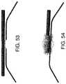
- FIG. 53depicts a dual drop lead assembly for 250 MCM cable with wires exposed at nexus
- FIG. 54depicts the end of string for a dual drop lead assembly for 250 MCM cable with the overmold depicted in phantom;
- FIG. 55depicts a single drop lead assembly for 250 MCM cable with the overmold depicted in phantom;
- FIG. 56depicts the overmold for a single drop lead assembly for 250 MCM cable
- FIG. 57depicts a single drop lead assembly for 250 MCM cable with undermold shown
- FIG. 58depicts the undermold for a single drop lead assembly for 250 MCM cable
- FIG. 59depicts a single drop lead assembly for 250 MCM cable with wires exposed at nexus
- FIG. 60depicts the end of string for a single drop lead assembly for 250 MCM cable with the overmold depicted in phantom;
- FIG. 61depicts a compression lug.
- a system of the present inventiongenerally includes a plurality of solar panels 30 that are electrically coupled to form solar arrays 32 a , 32 b , and so forth.
- Panels 30are preferably coupled using wire harnesses 34 which are commercially available from Shoals Technologies Group of Portland, Tenn.
- Each wire harnessincludes a plurality of branches each connecting to one solar panel, and a central trunk that terminates in wire harness connector 35 .
- Each wire harnessis connected at wire harness connector 35 to drop line connector 13 (not shown) of lead assembly 10 .
- solar arrays 32 a , 32 b and 32 care connected to a lead assembly 10 .
- a single lead assembly 10can reasonably accommodate approximately 200 Kw.
- FIG. 5depicts a positive lead assembly having in line fuses 29
- FIG. 6depicts a negative lead assembly without in line fuses
- positive lead assembliesmay lack in line fuses and negative lead assemblies may include in line fuses.
- lead assembly 10generally includes drop line 12 joined to feeder cable 14 at joint 17 . As shown in FIG. 35 , the drop line and feeder cable are held together by compression lug 20 , which is surrounded by undermold 22 ( FIG. 33 ), which is surrounded by overmold 24 ( FIG. 29 ). Overmold 24 preferably defines at least one aperture 25 for receiving zip-ties, and the like, for securing the assembly upon installation.
- Each drop line 12terminates in drop line connector 13 , which connects drop line 12 to wire harness connector 35 .
- Drop line 12is preferably constructed of 18 to 4 gauge wire, and drop line connectors 13 are preferably off-the-shelf connectors such as MC4/PV-KBT4/6I-UR & PV-KST4/6I-UR from Multi-Contact of Windsor, Calif.
- Joint 17 of lead assembly 10may include a single drop line 12 , as shown in FIG. 30 , or dual drop lines 12 , as shown in FIG. 29 , corresponding with connecting to a single wire harness or two wire harnesses, respectively. Whether a single or dual drop line is most suitable depends on the configuration of the solar arrays in a field.
- joints 17 and corresponding drop lines 12can be spaced close together (approximately 15 cm), or far apart (approximately 15000 cm), along feeder cable 14 , depending on the density of solar panels. Also, spacing of joints 17 and corresponding drop lines 12 can vary on a single lead assembly.
- Trunk buss jumper 27is essentially an “extension cord” which is economical to use in some configurations, for example where portions of feeder cable 14 are installed at different times. In another situation, trunk buss jumper 27 could be buried underground and feeder cable 14 above ground. Being able in install these components independent of one another can offer much more diversity. Trunk buss jumper 27 could also be utilized if there are a significant number of varying lengths from solar array 32 to inverter 38 .
- Trunk buss jumper 27could also be utilized if there is a substantial distance (greater than >50 meters) to travel from closest solar array 32 to inverter 38 and it would be wasteful to use a lead assembly with unused drop lines.
- the other end of feeder cable 14terminates in joint 17 having end piece 26 , which is typically installed at the solar array located furthest from the inverter.
- feeder cable 14includes feeder cable connector 15 at both terminal ends so feeder cables 14 can be connected one-to-another in an end-to-end orientation.
- one or both ends of feeder cables 14are blunt cut for subsequent manual connection, for example stripping and crimping to connectors or other segments of feeder cable.
- Feeder cable 14is preferably constructed of 6 gauge to 1000 MCM wire, with the specific wire chosen based on factors such as the number of associated drop lines and the distance between the connection and downstream inverter and whether or not feeder cable 14 is of aluminum or copper construction.
- Feeder cable connectors 15are preferably off-the-shelf connectors such as KBT10BV & KST10BV from Multi-Contact of Windsor, Calif.
- drop line 12 and feeder cable 14electrically couple at nexus 19 of joint 17 .
- Thisis preferably accomplished by stripping wire insulation 16 from corresponding segments of drop line 12 and feeder cable 14 , adjoining respective segments of exposed wire 18 , and securing contact between the segments of exposed wire by employing compression lug 20 .
- Compression lug 20is preferably surrounded by undermold 22 , which is preferably composed of RTP 2099E ⁇ 127663 from RTP Co. of Winona, Minn. that has been applied by injection molding. As shown in FIG.
- undermold 22is preferably surrounded by overmold 24 , which is preferably composed of RTP 199 ⁇ 124807 from RTP Co of Winona, Minn. that has been applied by injection molding.
- the resulting assemblyis profoundly durable, resistant to environmental factors such as temperature fluctuations, debris, and moisture, and is strong enough to be buried.
- a system of the present inventiondoesn't require a combiner box. Rather, lead assemblies 10 effectively “combine” the power from solar arrays 32 and deliver it to inverter 38 . As shown in FIG. 3 , the present invention also eliminates the need of DC feeders, which would carry power from the combiner box to the inverter in a conventional system. Also, the need for fuses can be eliminated by using drop lines including in line fuses 29 , as shown in the lower assembly of FIG. 27 . Appropriate fuses include of HP10x from Mersen of Newburyport, Mass.
- An embodiment of the present inventionpreferably has the following specifications: Voltage rating of 600 VDC/1000 VDC/1500 VDC; Maximum branch current of 30 amps per string; Maximum overcurrent protection of 30 amps per string; maximum trunk cable size of 750 MCM; and Maximum ambient operating temperature of 50° C., although other embodiments beyond these specifications are within the scope of the inventions.
Landscapes
- Photovoltaic Devices (AREA)
- Connector Housings Or Holding Contact Members (AREA)
Abstract
Description
- 10—Lead assembly;
- 12—Drop line;
- 13—Drop line connector;
- 14—Feeder cable;
- 15—Feeder cable connector;
- 16—Insulation;
- 17—Joint;
- 18—Exposed wire;
- 19—Nexus;
- 20—Compression lug;
- 22—Undermold;
- 24—Overmold;
- 25—Aperture;
- 27—Trunk buss jumper;
- 29—In line fuse;
- 30—Solar panel;
- 32—Solar array;
- 34—Wire harness;
- 35—Wire harness connector;
- 36—Combiner box; and
- 38—Inverter.
Claims (15)
Priority Applications (7)
| Application Number | Priority Date | Filing Date | Title |
|---|---|---|---|
| US14/849,458US10992254B2 (en) | 2014-09-09 | 2015-09-09 | Lead assembly for connecting solar panel arrays to inverter |
| US17/301,609US11689153B2 (en) | 2014-09-09 | 2021-04-08 | Lead assembly for connecting solar panel arrays to inverter |
| US18/341,655US12015375B2 (en) | 2014-09-09 | 2023-06-26 | Lead assembly for connecting solar panel arrays to inverter |
| US18/523,464US12015376B2 (en) | 2014-09-09 | 2023-11-29 | Lead assembly for connecting solar panel arrays to inverter |
| US18/739,127US20240333210A1 (en) | 2014-09-09 | 2024-06-10 | Lead assembly for connecting solar panel arrays to inverter |
| US19/021,810US20250158566A1 (en) | 2014-09-09 | 2025-01-15 | Lead assembly for connecting solar panel arrays to inverter |
| US19/086,937US12407295B2 (en) | 2014-09-09 | 2025-03-21 | Lead assembly for connecting solar panel arrays to inverter |
Applications Claiming Priority (2)
| Application Number | Priority Date | Filing Date | Title |
|---|---|---|---|
| US201462047773P | 2014-09-09 | 2014-09-09 | |
| US14/849,458US10992254B2 (en) | 2014-09-09 | 2015-09-09 | Lead assembly for connecting solar panel arrays to inverter |
Related Child Applications (1)
| Application Number | Title | Priority Date | Filing Date |
|---|---|---|---|
| US17/301,609ContinuationUS11689153B2 (en) | 2014-09-09 | 2021-04-08 | Lead assembly for connecting solar panel arrays to inverter |
Publications (2)
| Publication Number | Publication Date |
|---|---|
| US20160072431A1 US20160072431A1 (en) | 2016-03-10 |
| US10992254B2true US10992254B2 (en) | 2021-04-27 |
Family
ID=55438454
Family Applications (8)
| Application Number | Title | Priority Date | Filing Date |
|---|---|---|---|
| US14/849,458ActiveUS10992254B2 (en) | 2014-09-09 | 2015-09-09 | Lead assembly for connecting solar panel arrays to inverter |
| US17/301,609ActiveUS11689153B2 (en) | 2014-09-09 | 2021-04-08 | Lead assembly for connecting solar panel arrays to inverter |
| US18/341,655ActiveUS12015375B2 (en) | 2014-09-09 | 2023-06-26 | Lead assembly for connecting solar panel arrays to inverter |
| US18/523,464ActiveUS12015376B2 (en) | 2014-09-09 | 2023-11-29 | Lead assembly for connecting solar panel arrays to inverter |
| US18/739,127PendingUS20240333210A1 (en) | 2014-09-09 | 2024-06-10 | Lead assembly for connecting solar panel arrays to inverter |
| US19/021,810PendingUS20250158566A1 (en) | 2014-09-09 | 2025-01-15 | Lead assembly for connecting solar panel arrays to inverter |
| US19/078,979PendingUS20250211163A1 (en) | 2014-09-09 | 2025-03-13 | Lead assembly for connecting solar panel arrays to inverter |
| US19/086,937ActiveUS12407295B2 (en) | 2014-09-09 | 2025-03-21 | Lead assembly for connecting solar panel arrays to inverter |
Family Applications After (7)
| Application Number | Title | Priority Date | Filing Date |
|---|---|---|---|
| US17/301,609ActiveUS11689153B2 (en) | 2014-09-09 | 2021-04-08 | Lead assembly for connecting solar panel arrays to inverter |
| US18/341,655ActiveUS12015375B2 (en) | 2014-09-09 | 2023-06-26 | Lead assembly for connecting solar panel arrays to inverter |
| US18/523,464ActiveUS12015376B2 (en) | 2014-09-09 | 2023-11-29 | Lead assembly for connecting solar panel arrays to inverter |
| US18/739,127PendingUS20240333210A1 (en) | 2014-09-09 | 2024-06-10 | Lead assembly for connecting solar panel arrays to inverter |
| US19/021,810PendingUS20250158566A1 (en) | 2014-09-09 | 2025-01-15 | Lead assembly for connecting solar panel arrays to inverter |
| US19/078,979PendingUS20250211163A1 (en) | 2014-09-09 | 2025-03-13 | Lead assembly for connecting solar panel arrays to inverter |
| US19/086,937ActiveUS12407295B2 (en) | 2014-09-09 | 2025-03-21 | Lead assembly for connecting solar panel arrays to inverter |
Country Status (1)
| Country | Link |
|---|---|
| US (8) | US10992254B2 (en) |
Cited By (5)
| Publication number | Priority date | Publication date | Assignee | Title |
|---|---|---|---|---|
| US20230116099A1 (en)* | 2020-04-03 | 2023-04-13 | Nexans | Electrical power supply cable comprising a fuse and an overmolded fuse protection element with overthickness |
| WO2024050117A1 (en) | 2022-09-01 | 2024-03-07 | Shoals Technologies Group, Llc | Pedestal base and riser to mount electric vehicle chargers |
| WO2024050116A1 (en) | 2022-09-01 | 2024-03-07 | Shoals Technologies Group, Llc | Pedestal base for an electric vehicle charger with a built in pedestal |
| US12015375B2 (en) | 2014-09-09 | 2024-06-18 | Shoals Technologies Group, Llc | Lead assembly for connecting solar panel arrays to inverter |
| WO2025029753A1 (en) | 2023-07-28 | 2025-02-06 | Shoals Technologies Group, Llc | Methods and systems to monitor photovoltaic systems |
Families Citing this family (10)
| Publication number | Priority date | Publication date | Assignee | Title |
|---|---|---|---|---|
| USD871320S1 (en)* | 2017-10-27 | 2019-12-31 | Heraeus Deutschland GmbH & Co. KG | Solar cell connector with stripes for a solar panel |
| JP1613169S (en)* | 2017-11-30 | 2018-09-10 | ||
| USD879031S1 (en)* | 2018-06-01 | 2020-03-24 | Sunpower Corporation | Textured solar panel |
| USD861591S1 (en)* | 2018-06-04 | 2019-10-01 | Solaero Technologies Corp. | Mosaic solar cell |
| EE01486U1 (en)* | 2019-03-26 | 2020-02-17 | Energogen OÜ | Method for creating a power production device |
| WO2023212378A1 (en)* | 2022-04-29 | 2023-11-02 | Shoals Technologies Group, Llc | Ev charger system power platform |
| US20240055796A1 (en)* | 2022-08-11 | 2024-02-15 | Rosendin Electric, Inc. | Connector for a dc voltage connection to a platform |
| WO2024072830A1 (en)* | 2022-09-26 | 2024-04-04 | Shoals Technologies Group, Llc | Lead assembly with an integral fuse |
| US20240235469A9 (en)* | 2022-10-25 | 2024-07-11 | Wind Turbine & Energy Cables, Corp. | Electrical bus system and components |
| WO2025137154A1 (en)* | 2023-12-20 | 2025-06-26 | Shoals Technologies Group, Llc | Anti-shrink back device |
Citations (12)
| Publication number | Priority date | Publication date | Assignee | Title |
|---|---|---|---|---|
| US3852516A (en)* | 1973-05-02 | 1974-12-03 | C Ploog | Moisture proof splice enclosure for electrical application |
| US5316789A (en)* | 1991-05-09 | 1994-05-31 | Sumitomo Wiring Systems, Ltd. | Method of water-proofing a connected portion of electric wires |
| US6268559B1 (en)* | 1999-03-24 | 2001-07-31 | Kaneka Corporation | Photovoltaic generation system, wiring apparatus for photovoltaic generation system, and wiring structure therefor |
| US20090300909A1 (en)* | 2008-06-10 | 2009-12-10 | Southwire Company | Low temperature applications of flame retardant power cable |
| US20100139733A1 (en)* | 2009-08-18 | 2010-06-10 | General Electric Company | Fused wiring harness for a photovoltaic system |
| US20100258157A1 (en)* | 2009-04-13 | 2010-10-14 | Smk Corporation | Watertight connector and photovoltaic power generating apparatus |
| US20110011642A1 (en)* | 2009-07-14 | 2011-01-20 | Dean Solon | Low leakage electrical joints and wire harnesses, and method of making the same |
| US20110174521A1 (en)* | 2010-01-15 | 2011-07-21 | Servicios Condumex S.A. De Cv | Flame retardant, low smoke emission, halogen free 600 V energy cable with polyolefin insulation and polyamide jacket |
| US20110209741A1 (en)* | 2010-03-01 | 2011-09-01 | Dean Solon | Solar energy wire harness with in-line fuses |
| US20120085040A1 (en)* | 2010-10-07 | 2012-04-12 | Delphi Technologies, Inc. | Low profile electrical connection system |
| US20120217973A1 (en)* | 2011-02-28 | 2012-08-30 | Tigo Energy, Inc. | System and Method for Flash Bypass |
| US20130269746A1 (en)* | 2012-04-11 | 2013-10-17 | Schneider Electric USA, Inc. | Tapered trunking system with distributed combiner |
Family Cites Families (170)
| Publication number | Priority date | Publication date | Assignee | Title |
|---|---|---|---|---|
| US1831002A (en) | 1929-06-24 | 1931-11-10 | Hickey Fuse & Mfg Company | Fuse |
| US2700085A (en) | 1953-07-30 | 1955-01-18 | Westinghouse Air Brake Co | Electrical fuse device |
| US2808487A (en) | 1956-04-12 | 1957-10-01 | Chase Shawmut Co | High voltage fuses |
| NL254817A (en) | 1959-08-13 | |||
| NL130678C (en) | 1960-07-15 | 1900-01-01 | ||
| NL295669A (en) | 1962-07-23 | |||
| US3296399A (en) | 1965-10-19 | 1967-01-03 | Chase Shawmut Co | Electric high-voltage fuse having means for effecting sequential vaporization of portions of fusible element |
| JPS466774Y1 (en) | 1966-11-24 | 1971-03-09 | ||
| US3686603A (en) | 1969-04-30 | 1972-08-22 | Westinghouse Electric Corp | Electrical connector |
| US3686604A (en) | 1969-08-12 | 1972-08-22 | Rte Corp | Current interrupting safe break terminator |
| US3781745A (en) | 1969-09-10 | 1973-12-25 | Joslyn Mfg & Supply Co | Fused coupler assembly |
| DE6940839U (en) | 1969-10-21 | 1971-04-01 | Borgmann Kg W | FIRE-WEATHER PROTECTED MELT FUSE. |
| US3559141A (en) | 1969-10-23 | 1971-01-26 | Gen Electric | Underground electric power cable fuse housing having a semi-conductive corona shield |
| GB1324563A (en)* | 1971-03-03 | 1973-07-25 | British Insulated Callenders | Multi-conductor electric cables |
| US3678432A (en) | 1971-04-26 | 1972-07-18 | Gen Electric | Vented fuse module for underground power cable system |
| JPS555138Y2 (en) | 1971-04-26 | 1980-02-06 | ||
| US3818407A (en) | 1972-09-25 | 1974-06-18 | Amerace Esna Corp | High voltage fuse enclosure |
| US3795757A (en) | 1972-10-02 | 1974-03-05 | British Insulated Callenders | Distribution cable with permanently connected branch cables and method of effecting said connections |
| US3946351A (en) | 1975-02-28 | 1976-03-23 | Mcgraw-Edison Company | Shielded fuse assembly |
| JPS585292Y2 (en) | 1976-02-24 | 1983-01-29 | 日立電線株式会社 | Cable with branch line |
| US4077697A (en) | 1976-04-19 | 1978-03-07 | Yates Curtis D | Wire connecting devices |
| JPS52135081A (en) | 1976-05-06 | 1977-11-11 | Fujikura Ltd | Prefabricated cable unit with branch lines |
| US4060785A (en) | 1976-09-13 | 1977-11-29 | Kearney-National Inc. | Enclosing structure for a high voltage electric fuse |
| JPS5384073U (en) | 1976-12-14 | 1978-07-11 | ||
| US4251304A (en) | 1979-04-19 | 1981-02-17 | Raychem Corporation | Heat-recoverable articles and their use |
| US4308515A (en) | 1980-02-07 | 1981-12-29 | Commercial Enclosed Fuse Co. | Fuse apparatus for high electric currents |
| CA1216015A (en) | 1982-06-14 | 1986-12-30 | Joel L. Fritsche | Shielded electric components |
| US4464583A (en)* | 1983-03-04 | 1984-08-07 | Mcgraw-Edison Company | Apparatus for bonding and protecting electrical cable shields |
| JPS608573B2 (en) | 1983-04-19 | 1985-03-04 | 金邦電気株式会社 | Fuse for electric wire |
| US4778948A (en) | 1983-08-04 | 1988-10-18 | Raychem Limited | Cable joint |
| GB2164805B (en) | 1983-09-20 | 1988-07-13 | Raychem Corp | Cable joints and terminations |
| US4780598A (en) | 1984-07-10 | 1988-10-25 | Raychem Corporation | Composite circuit protection devices |
| JPS60236430A (en) | 1985-04-17 | 1985-11-25 | 日本高圧電気株式会社 | Method of molding insulating case in sealed wire fuse |
| US4625196A (en) | 1985-06-24 | 1986-11-25 | Rte Corporation | Modular under oil expulsion fuse cartridge assembly |
| JP2670687B2 (en)* | 1988-07-11 | 1997-10-29 | 東京電力株式会社 | Low-voltage trunk branch device |
| CH677419A5 (en) | 1989-03-17 | 1991-05-15 | Skyline Holding Ag | |
| US4947149A (en) | 1989-09-27 | 1990-08-07 | Gould, Inc. | Electrical fuse with improved casing |
| JPH0787880B2 (en) | 1990-05-31 | 1995-09-27 | 東レ株式会社 | Manufacturing method of polyester raw cotton for wadding |
| JPH04171359A (en) | 1990-11-02 | 1992-06-18 | Jidosha Kiki Co Ltd | Transmission operating device |
| US5572804A (en) | 1991-09-26 | 1996-11-12 | Retama Technology Corp. | Shoe sole component and shoe sole component construction method |
| US5316502A (en) | 1992-04-10 | 1994-05-31 | Union Connector Co., Inc. | Electrical connector with circuit protection |
| JPH0684410A (en) | 1992-09-01 | 1994-03-25 | Toyokuni Densen Kk | Wiring branch cable for electric lamp or the like |
| JP3004630U (en) | 1994-05-25 | 1994-11-22 | 旭電機株式会社 | Insulation structure for insulation cable branch connection |
| JPH08289450A (en) | 1995-04-14 | 1996-11-01 | Chubu Electric Power Co Inc | Wire branch structure |
| JPH08289451A (en) | 1995-04-14 | 1996-11-01 | Chubu Electric Power Co Inc | Wire branch connection connector |
| JP3819961B2 (en) | 1996-03-05 | 2006-09-13 | 株式会社フジタ | Composite prefabricated cable for weak electricity |
| US5726851A (en) | 1996-04-10 | 1998-03-10 | Joslyn Electronic Systems Corporation | Coaxial cable fuse apparatus |
| JPH10135499A (en) | 1996-10-31 | 1998-05-22 | Tokyo Electric Power Co Inc:The | Solar cell module wiring connection method |
| US6777043B2 (en) | 1998-04-03 | 2004-08-17 | S & C Electric Co. | Fuse tube and method of manufacture thereof |
| JP2000004516A (en) | 1998-06-15 | 2000-01-07 | Sumitomo Electric Ind Ltd | Branch connection structure of low voltage cable |
| US5903209A (en) | 1998-08-07 | 1999-05-11 | Thomas & Betts International, Inc. | Encapsulated fuse with corona shield |
| JP3004630B1 (en) | 1998-08-28 | 2000-01-31 | 有限会社土壌保全研究所 | Soil disease control materials |
| CN2336459Y (en) | 1998-10-19 | 1999-09-01 | 杨胜武 | Prefabricated branch cable |
| JP2000348836A (en) | 1999-06-07 | 2000-12-15 | Sumitomo Wiring Syst Ltd | Trifurcate-type connector |
| GB9918282D0 (en)* | 1999-08-03 | 1999-10-06 | Draka Uk Limited | Cable connector |
| US6265665B1 (en)* | 1999-11-30 | 2001-07-24 | Homac Manufacturing Company | Gel-filled casing for an electrical connection and associated method |
| JP4080663B2 (en) | 2000-02-17 | 2008-04-23 | 行田電線株式会社 | Cable branch molding method |
| CN2411542Y (en) | 2000-03-09 | 2000-12-20 | 杨胜武 | Multi-core prefabricated branch cable |
| JP4169490B2 (en) | 2001-05-01 | 2008-10-22 | 株式会社Msk | Solar cell module wiring cable and solar cell module wiring structure using the cable |
| CN1395056A (en) | 2001-07-06 | 2003-02-05 | 陈玄德 | Rope light and its manufacturing method |
| JP2003031834A (en) | 2001-07-13 | 2003-01-31 | Kubota Corp | Solar cell module wiring cable |
| JP2003077584A (en) | 2001-09-06 | 2003-03-14 | Yukita Electric Wire Co Ltd | Waterproof connector |
| JP3652318B2 (en)* | 2002-04-01 | 2005-05-25 | 積水化学工業株式会社 | Roofing with solar cells |
| CN2562350Y (en) | 2002-06-18 | 2003-07-23 | 樊邦弘 | Overcurrent protector on power wire |
| JP2005039981A (en) | 2003-02-28 | 2005-02-10 | Toyokuni Electric Cable Co Ltd | Laying method of main cable in multistory building and main cable |
| JP4044484B2 (en) | 2003-04-28 | 2008-02-06 | 株式会社カネカ | SOLAR CELL POWER GENERATOR, WIRING EQUIPMENT FOR THE DEVICE, AND WIRING STRUCTURE |
| KR200329882Y1 (en) | 2003-07-31 | 2003-10-11 | 한국전력공사 | Safety for industrial line |
| US20120181973A1 (en) | 2003-08-29 | 2012-07-19 | Robert Lyden | Solar array resembling natural foliage including means for wireless transmission of electric power |
| CA2542300C (en) | 2003-10-10 | 2012-06-12 | G & W Electric Company | Encapsulated fuse with corona shield |
| CN2660691Y (en) | 2003-11-03 | 2004-12-01 | 南京永恒电器有限公司 | Bushing cable tap joint able to connect in-situ construction |
| US7436283B2 (en) | 2003-11-20 | 2008-10-14 | Cooper Technologies Company | Mechanical reinforcement structure for fuses |
| US7044776B2 (en)* | 2003-12-02 | 2006-05-16 | King Jr Lloyd Herbert | Wire connector |
| JP4606774B2 (en) | 2004-05-18 | 2011-01-05 | 矢崎総業株式会社 | Cable with branch |
| CN2785100Y (en) | 2005-01-13 | 2006-05-31 | 宝胜科技创新股份有限公司 | Power cable with bidirectional K type branch |
| EP1729317B1 (en) | 2005-06-02 | 2007-10-24 | Wickmann-Werke GmbH | Helically wound fusible conductor for fuse element with plastic sealing |
| JP2009503768A (en) | 2005-07-22 | 2009-01-29 | リッテルフューズ,インコーポレイティド | Electrical device with integral fused conductor |
| US8242874B2 (en) | 2005-08-23 | 2012-08-14 | Lear Corporation | Electrical connector housing |
| DE202006007613U1 (en) | 2006-05-11 | 2006-08-17 | Beck, Manfred | Photovoltaic system for production of electrical energy, has thermal fuse provided in connecting lines between photovoltaic unit and hand-over point, where fuse has preset marginal temperature corresponding to fire temperature |
| DE102006032275B3 (en) | 2006-07-12 | 2008-01-03 | Tyco Electronics Amp Gmbh | Electrical connecting device for connecting solar module with solar module arrangement by electrical conductor, has part of housing and part of contacted electrical conductor, which are surrounded by common sleeve |
| US20080011347A1 (en) | 2006-07-14 | 2008-01-17 | Hitachi Cable, Ltd. | Connecting lead wire for a solar battery module, method for fabricating same, and solar battery module using the connecting lead wire |
| JP4775907B2 (en) | 2006-11-22 | 2011-09-21 | Smk株式会社 | Waterproof connector and relay connector |
| JP4117850B1 (en) | 2006-12-28 | 2008-07-16 | 昭和シェル石油株式会社 | Current collecting cable |
| US7387537B1 (en) | 2007-01-03 | 2008-06-17 | Tyco Electronics Corporation | Connector system for solar cell roofing tiles |
| JP2008187814A (en) | 2007-01-30 | 2008-08-14 | Chugoku Electric Power Co Inc:The | Branch member, and connection method of branch cable |
| KR200446192Y1 (en) | 2007-06-27 | 2009-10-08 | 한국전력공사 | Compression Terminal Improved Wire Fuse |
| DE102008027189A1 (en) | 2007-07-10 | 2009-01-15 | Pfeffer, Roland | Safety element for photovoltaic arrangement, has two electrical contacts, which are spaced from each other by electrically isolating fuse body |
| JP2009148010A (en) | 2007-12-11 | 2009-07-02 | Exsym Corp | Closure filled with gel and branch cable joint |
| CN201134283Y (en) | 2007-12-27 | 2008-10-15 | 上海胜武电缆有限公司 | Inorganic mineral insulated fireproof prefabricated branch cables |
| DE202008016324U1 (en) | 2007-12-28 | 2009-03-19 | Blitzstrom Gmbh | Harness for photovoltaic systems |
| CN101527235B (en) | 2008-03-06 | 2011-12-21 | 颜琼章 | Overcurrent protection device and manufacturing method thereof |
| US8179224B2 (en) | 2008-04-17 | 2012-05-15 | Chun-Chang Yen | Overcurrent protection structure and method and apparatus for making the same |
| DE202008013119U1 (en) | 2008-05-09 | 2008-12-18 | Yamaichi Electronics Deutschland Gmbh | connector system |
| EP2124324A1 (en) | 2008-05-20 | 2009-11-25 | SMA Solar Technology AG | Photovoltaic converter |
| AU2009292595B2 (en) | 2008-09-10 | 2015-09-10 | Kaneka Corporation | Solar cell module and solar cell array |
| US20100090851A1 (en) | 2008-09-30 | 2010-04-15 | Bruce Hauser | Electrical extension cord |
| JP5384073B2 (en) | 2008-10-01 | 2014-01-08 | 矢崎エナジーシステム株式会社 | Cable with branch |
| JP2010123933A (en) | 2008-10-24 | 2010-06-03 | Asahi Kasei Chemicals Corp | Connection structure for photovoltaic power generation module |
| KR101702919B1 (en) | 2008-11-18 | 2017-02-06 | 타이코 일렉트로닉스 코포레이션 | Sealant-filled enclosures and methods for environmentally protecting a connection |
| JP4730794B2 (en) | 2009-01-26 | 2011-07-20 | Smk株式会社 | Branch connector |
| CA2757331A1 (en) | 2009-04-01 | 2010-10-07 | Nextronex Inc. | A grid tie solar system and a method |
| IT1394694B1 (en) | 2009-04-17 | 2012-07-13 | Palazzoli Spa | FUSE HOLDER DEVICE, PARTICULARLY FOR INTERLOCKED SOCKETS AND ELECTRIC APPLIANCES IN GENERAL |
| EP2241841A1 (en) | 2009-04-17 | 2010-10-20 | Sumika Polymer Compounds (France) SA | Moulded insulating collector |
| CN201387761Y (en) | 2009-04-24 | 2010-01-20 | 武汉新天地特种电缆有限公司 | Polyolefin insulated PVC sheathed fire-resistant prefabricated branch power cable |
| CN201536157U (en) | 2009-04-30 | 2010-07-28 | 比亚迪股份有限公司 | Connecting terminal of high-voltage cable |
| CN101923915A (en) | 2009-06-15 | 2010-12-22 | 张逸中 | High-voltage prefabricated branched cable |
| CN101577158A (en) | 2009-06-19 | 2009-11-11 | 蚌埠市双环电子集团有限公司 | Insulating wirewound moulded fusing resistor |
| JP5215472B2 (en) | 2009-08-20 | 2013-06-19 | 行田電線株式会社 | Waterproof connector |
| CN201518320U (en) | 2009-09-28 | 2010-06-30 | 深圳市创益科技发展有限公司 | Solar cell external electrode connecting device |
| US8207637B2 (en) | 2009-10-09 | 2012-06-26 | Solarbridge Technologies, Inc. | System and apparatus for interconnecting an array of power generating assemblies |
| KR200455299Y1 (en) | 2009-12-17 | 2011-08-29 | 이종호 | Insulation structure of temperature fuse and temperature sensor |
| WO2011076955A1 (en) | 2009-12-21 | 2011-06-30 | Prefabricados Uniblok, S.L.U. | Device for high-voltage electric connection between electric devices |
| DE102010002565B8 (en) | 2010-03-04 | 2012-03-22 | Tyco Electronics Amp Gmbh | Connecting device for a solar module |
| CN201682254U (en) | 2010-04-28 | 2010-12-22 | 无锡市华美电缆有限公司 | Branch connector structure of prefabricated branch cable |
| JP5583485B2 (en) | 2010-06-03 | 2014-09-03 | 日本高圧電気株式会社 | Electric wire fuse |
| JP4831505B1 (en) | 2010-06-08 | 2011-12-07 | 山一電機株式会社 | Waterproof structure for cable connector, plug connector, socket connector, and cable connector using the same |
| CN201750032U (en) | 2010-07-22 | 2011-02-16 | 昆山勃盛电子有限公司 | Photovoltaic power supply system integrated wiring harness |
| KR101179546B1 (en) | 2010-08-17 | 2012-09-05 | (주)엠에스테크비젼 | Repetitive Fuse |
| CN201845580U (en) | 2010-11-09 | 2011-05-25 | 安徽华宇电缆集团有限公司 | Branch connector type prefabricated branch cable |
| JP5689652B2 (en)* | 2010-11-10 | 2015-03-25 | エスアイアイ・プリンテック株式会社 | Liquid ejecting head, liquid ejecting apparatus, and method of manufacturing liquid ejecting head |
| JP5545187B2 (en) | 2010-11-24 | 2014-07-09 | 住友電装株式会社 | Protective material for wire harness |
| US20120125395A1 (en)* | 2010-11-24 | 2012-05-24 | First Solar, Inc | Method and apparatus facilitating electrical interconnection of a plurality of solar modules |
| CN201877150U (en) | 2010-12-06 | 2011-06-22 | 无锡江南电缆有限公司 | Prefabricated branch cable |
| CN201994507U (en) | 2010-12-20 | 2011-09-28 | 东莞宏威数码机械有限公司 | Solar battery cable |
| CN102117976A (en) | 2010-12-20 | 2011-07-06 | 东莞宏威数码机械有限公司 | Solar cell connection wire and manufacturing method thereof |
| US20120161919A1 (en) | 2010-12-22 | 2012-06-28 | Von Zur Muehlen Patrick A | Safety Fuse Holder Assembly |
| EP2495825A1 (en) | 2011-03-02 | 2012-09-05 | Lapp Engineering & Co. | Connector |
| CN201975362U (en) | 2011-04-26 | 2011-09-14 | 德国卡洛尔埃马克有限公司 | A New Type of High Voltage Fuse |
| US8454390B2 (en) | 2011-06-02 | 2013-06-04 | Cooper Technologies Company | Inline fuse holder assembly |
| CN202153443U (en) | 2011-07-04 | 2012-02-29 | 长沙安瑞电器有限公司 | Sealed wire harness |
| CN102332345B (en) | 2011-08-09 | 2013-01-16 | 兴乐电缆有限公司 | Manufacturing method for prefabricated branch flexible cable |
| CN202256574U (en) | 2011-08-11 | 2012-05-30 | 东莞市新金阳光电科技有限公司 | Fuse ON/OFF LED light display device |
| US8517768B2 (en) | 2011-08-11 | 2013-08-27 | Ideal Industries, Inc. | Breakaway fuse holder |
| EP2565899A1 (en) | 2011-08-30 | 2013-03-06 | Siemens Aktiengesellschaft | Pressure resistant housing for an electric component |
| US8723370B2 (en) | 2011-08-30 | 2014-05-13 | Renewable Power Conversion, Inc. | Photovoltaic string sub-combiner |
| CN202258411U (en) | 2011-09-08 | 2012-05-30 | 中国冶金矿业鞍山冶金设计研究院有限责任公司 | A kind of downhole lighting belt branch cable |
| US20130077249A1 (en) | 2011-09-26 | 2013-03-28 | Amphenol Technical Products International | Overmolded in-line photovoltaic current regulating and heat sink device |
| FR2983361B1 (en) | 2011-11-28 | 2013-12-27 | Michel Bechet | REMOVABLE ELECTRICAL PROTECTION DEVICE FOR SINGLE USE AND ITS USE IN A SOLAR POWER ELECTRICAL PHOTOVOLTAIC PRODUCTION PLANT |
| CN103165235A (en) | 2011-12-16 | 2013-06-19 | 上海市高桥电缆厂有限公司 | Mineral insulated soft fire-resistant branch cable |
| CN202434452U (en) | 2011-12-26 | 2012-09-12 | 东莞市思普太阳能科技有限公司 | Fuse socket for solar photovoltaic power generation system |
| CN102568970B (en) | 2011-12-26 | 2014-07-23 | 东莞市思普太阳能科技有限公司 | Fuse tube seat for solar photovoltaic power generation system |
| US8699209B2 (en) | 2012-01-10 | 2014-04-15 | Cooper Technologies Company | Externally fused enclosure for a solar power system |
| JP5889047B2 (en) | 2012-03-08 | 2016-03-22 | スリーエム イノベイティブ プロパティズ カンパニー | Insulating waterproof member and insulating waterproof method |
| EP2831953B1 (en) | 2012-03-27 | 2016-12-14 | Littelfuse, Inc. | Fuse end cap with crimpable terminal |
| US20130257154A1 (en) | 2012-03-27 | 2013-10-03 | General Electric Company | System for distributing electrical power supplied from a solar panel array |
| CN202524026U (en) | 2012-04-20 | 2012-11-07 | 上海胜华电气股份有限公司 | High-stability cable injection molding device |
| CN202758911U (en) | 2012-07-30 | 2013-02-27 | 东莞市新金阳光电科技有限公司 | Photovoltaic connectors that can replace fuses and diodes |
| CN202797033U (en) | 2012-08-21 | 2013-03-13 | 江苏九鼎光伏系统有限公司 | Photovoltaic counter current protector |
| JP2014050227A (en)* | 2012-08-31 | 2014-03-17 | Nishi Nippon Electric Wire & Cable Co Ltd | Photovoltaic power generation system and installation method for photovoltaic power generation system |
| DE102012218366B3 (en) | 2012-10-09 | 2014-02-06 | Enextra Gmbh | Photovoltaic system for creation of electrical direct voltage, has photovoltaic module between definable string input and output, where module is able to be looped, and each remaining string input is connected to associated string output |
| US8911264B2 (en) | 2012-10-22 | 2014-12-16 | Cooper Technologies Company | Connector with integral fuse holder |
| CN103000468B (en) | 2012-11-16 | 2015-06-10 | 施特格亚太投资有限公司 | Fuse tube seat for solar photovoltaic power generation system |
| CN202977351U (en) | 2012-11-16 | 2013-06-05 | 施特格亚太投资有限公司 | Fuse socket for solar photovoltaic power generation system |
| CN203038709U (en) | 2012-12-17 | 2013-07-03 | 无锡江南电缆有限公司 | Fireproof-type multi-core branch cable |
| CN203118602U (en) | 2013-03-12 | 2013-08-07 | 成都康达电缆有限公司 | Armour prefabricated branch cable with copper-clad aluminum as conductor |
| CN203102969U (en) | 2013-03-12 | 2013-07-31 | 成都康达电缆有限公司 | A copper-clad aluminum conductor halogen-free low-smoke flame-retardant prefabricated branch cable |
| JP6054246B2 (en) | 2013-05-19 | 2016-12-27 | ユニコン電子株式会社 | Fixing structure and fixing method of solar cell output cable to connection box |
| US10553739B1 (en) | 2013-06-03 | 2020-02-04 | Shoals Technologies Group, Llc | Photovoltaic in line fuse connector assembly having an integral fuse |
| DE202013012612U1 (en) | 2013-06-14 | 2018-01-18 | Phoenix Contact Gmbh & Co. Kg | Cable module for the module inverter of a photovoltaic generator |
| EP2838104A1 (en) | 2013-08-12 | 2015-02-18 | Siemens Aktiengesellschaft | Subsea fuse |
| JP2015060813A (en) | 2013-09-20 | 2015-03-30 | ホシデン株式会社 | Branch connector |
| KR101428689B1 (en) | 2014-01-07 | 2014-08-11 | 양승일 | Cable connecting apparatus and cable connecting method using the same |
| JP2015133822A (en) | 2014-01-13 | 2015-07-23 | 株式会社オートネットワーク技術研究所 | Cable connection structure and cable connection method |
| JP2015198508A (en)* | 2014-04-01 | 2015-11-09 | 株式会社東芝 | Photovoltaic power generation device |
| CN104021860B (en) | 2014-06-19 | 2016-12-07 | 远东电缆有限公司 | A kind of aluminium alloy prefabricated branch cable and manufacture method thereof |
| CN203967369U (en) | 2014-06-30 | 2014-11-26 | 天津六〇九电缆有限公司 | A kind of tracker photovoltaic wire tread assembly |
| US10992254B2 (en) | 2014-09-09 | 2021-04-27 | Shoals Technologies Group, Llc | Lead assembly for connecting solar panel arrays to inverter |
| CN104464920B (en) | 2014-12-25 | 2017-02-01 | 宝胜科技创新股份有限公司 | Preparation method of flexible water-blocking ready-made branch fireproof cable connector |
| CN204463897U (en) | 2015-03-11 | 2015-07-08 | 昆明多宝电缆有限公司 | A kind of water proof type pre-branched cable |
| CN204558134U (en) | 2015-04-09 | 2015-08-12 | 江苏中辰电缆有限公司 | Be applicable to cable connection body that is multi-core integrated, heavy in section prefabricated branch cable |
| CN204760094U (en) | 2015-06-03 | 2015-11-11 | 上海众业通电缆有限公司 | Mineral insulation branch cable that prevents fires |
- 2015
- 2015-09-09USUS14/849,458patent/US10992254B2/enactiveActive
- 2021
- 2021-04-08USUS17/301,609patent/US11689153B2/enactiveActive
- 2023
- 2023-06-26USUS18/341,655patent/US12015375B2/enactiveActive
- 2023-11-29USUS18/523,464patent/US12015376B2/enactiveActive
- 2024
- 2024-06-10USUS18/739,127patent/US20240333210A1/enactivePending
- 2025
- 2025-01-15USUS19/021,810patent/US20250158566A1/enactivePending
- 2025-03-13USUS19/078,979patent/US20250211163A1/enactivePending
- 2025-03-21USUS19/086,937patent/US12407295B2/enactiveActive
Patent Citations (12)
| Publication number | Priority date | Publication date | Assignee | Title |
|---|---|---|---|---|
| US3852516A (en)* | 1973-05-02 | 1974-12-03 | C Ploog | Moisture proof splice enclosure for electrical application |
| US5316789A (en)* | 1991-05-09 | 1994-05-31 | Sumitomo Wiring Systems, Ltd. | Method of water-proofing a connected portion of electric wires |
| US6268559B1 (en)* | 1999-03-24 | 2001-07-31 | Kaneka Corporation | Photovoltaic generation system, wiring apparatus for photovoltaic generation system, and wiring structure therefor |
| US20090300909A1 (en)* | 2008-06-10 | 2009-12-10 | Southwire Company | Low temperature applications of flame retardant power cable |
| US20100258157A1 (en)* | 2009-04-13 | 2010-10-14 | Smk Corporation | Watertight connector and photovoltaic power generating apparatus |
| US20110011642A1 (en)* | 2009-07-14 | 2011-01-20 | Dean Solon | Low leakage electrical joints and wire harnesses, and method of making the same |
| US20100139733A1 (en)* | 2009-08-18 | 2010-06-10 | General Electric Company | Fused wiring harness for a photovoltaic system |
| US20110174521A1 (en)* | 2010-01-15 | 2011-07-21 | Servicios Condumex S.A. De Cv | Flame retardant, low smoke emission, halogen free 600 V energy cable with polyolefin insulation and polyamide jacket |
| US20110209741A1 (en)* | 2010-03-01 | 2011-09-01 | Dean Solon | Solar energy wire harness with in-line fuses |
| US20120085040A1 (en)* | 2010-10-07 | 2012-04-12 | Delphi Technologies, Inc. | Low profile electrical connection system |
| US20120217973A1 (en)* | 2011-02-28 | 2012-08-30 | Tigo Energy, Inc. | System and Method for Flash Bypass |
| US20130269746A1 (en)* | 2012-04-11 | 2013-10-17 | Schneider Electric USA, Inc. | Tapered trunking system with distributed combiner |
Non-Patent Citations (2)
| Title |
|---|
| "Wire Gauges—Current Ratings" [retrieved from https://web.archive.org/web/20140715051530/www.engineeringtoolbox.com/wire-gauges-d_419.html on Jun. 6, 2019] (Year: 2015).* |
| Definition of "working voltage" [retrieved from https://encyclopedia2.thefreedictionary.com/voltage+rating on Sep. 18, 2018].* |
Cited By (7)
| Publication number | Priority date | Publication date | Assignee | Title |
|---|---|---|---|---|
| US12015375B2 (en) | 2014-09-09 | 2024-06-18 | Shoals Technologies Group, Llc | Lead assembly for connecting solar panel arrays to inverter |
| US12015376B2 (en) | 2014-09-09 | 2024-06-18 | Shoals Technologies Group, Llc | Lead assembly for connecting solar panel arrays to inverter |
| US12407295B2 (en) | 2014-09-09 | 2025-09-02 | Shoals Technologies Group, Llc | Lead assembly for connecting solar panel arrays to inverter |
| US20230116099A1 (en)* | 2020-04-03 | 2023-04-13 | Nexans | Electrical power supply cable comprising a fuse and an overmolded fuse protection element with overthickness |
| WO2024050117A1 (en) | 2022-09-01 | 2024-03-07 | Shoals Technologies Group, Llc | Pedestal base and riser to mount electric vehicle chargers |
| WO2024050116A1 (en) | 2022-09-01 | 2024-03-07 | Shoals Technologies Group, Llc | Pedestal base for an electric vehicle charger with a built in pedestal |
| WO2025029753A1 (en) | 2023-07-28 | 2025-02-06 | Shoals Technologies Group, Llc | Methods and systems to monitor photovoltaic systems |
Also Published As
| Publication number | Publication date |
|---|---|
| US20210226581A1 (en) | 2021-07-22 |
| US20230336118A1 (en) | 2023-10-19 |
| US20160072431A1 (en) | 2016-03-10 |
| US12015375B2 (en) | 2024-06-18 |
| US11689153B2 (en) | 2023-06-27 |
| US12407295B2 (en) | 2025-09-02 |
| US20250211163A1 (en) | 2025-06-26 |
| US20250219573A1 (en) | 2025-07-03 |
| US20250158566A1 (en) | 2025-05-15 |
| US20240333210A1 (en) | 2024-10-03 |
| US12015376B2 (en) | 2024-06-18 |
| US20240097614A1 (en) | 2024-03-21 |
Similar Documents
| Publication | Publication Date | Title |
|---|---|---|
| US11689153B2 (en) | Lead assembly for connecting solar panel arrays to inverter | |
| US9553225B2 (en) | Tapered trunking system with distributed combiner | |
| US8647155B2 (en) | Electrical-conductive assembly for signal cable | |
| US8272883B1 (en) | Intersystem grounding bridge and system | |
| US11536252B2 (en) | Down conductor connection system, wind turbine lightning protection system, and method for arranging a down conductor connection system | |
| US8779623B2 (en) | Cable bus | |
| CN104797464A (en) | Wire harness and manufacturing method thereof | |
| US10553739B1 (en) | Photovoltaic in line fuse connector assembly having an integral fuse | |
| US20150280439A1 (en) | Apparatus for grounding interconnected electrical components and assemblies | |
| EP2693576A1 (en) | Electric power base, electric power gateway, and electric power gateway body | |
| US20180269827A1 (en) | Parallel-connected solar power converter system | |
| US20110269337A1 (en) | Apparatus and method for connecting emergency power | |
| US9088147B2 (en) | Electrical line furnished with screen-break junctions | |
| KR20240040309A (en) | Electric track connection bracket assembly | |
| CN207718032U (en) | A kind of insulating splice closure for line feeder fiber composite overhead ground wire | |
| CN106024144A (en) | Compact type flame-retardant weather-resistant flat cable and production process thereof | |
| US10411645B1 (en) | Photovoltaic module sourced control power | |
| US10192706B2 (en) | Undermolded and overmolded fuse joints | |
| CN103187123A (en) | Cross-connection grounding coaxial cable | |
| CN104143739A (en) | A power grid transmission line convenient for wiring and its connection method | |
| US20130168124A1 (en) | Busway for High Voltage, High Current Applications | |
| KR101095703B1 (en) | Outer case for ultra high voltage power cable connection | |
| CN101593572A (en) | A kind of three-selection power cord | |
| TH1901005109A (en) | Electrical Wiring Unit for Indoor Wiring | |
| CN101593919A (en) | A kind of double-headed and triple-headed combined plug |
Legal Events
| Date | Code | Title | Description |
|---|---|---|---|
| AS | Assignment | Owner name:SHOALS TECHNOLOGIES GROUP, LLC, TENNESSEE Free format text:ASSIGNMENT OF ASSIGNORS INTEREST;ASSIGNOR:SOLON, DEAN;REEL/FRAME:036910/0773 Effective date:20151029 | |
| AS | Assignment | Owner name:MB FINANCIAL BANK, N.A., AS ADMINISTRATIVE AGENT, ILLINOIS Free format text:SECURITY INTEREST;ASSIGNOR:SHOALS TECHNOLOGIES GROUP, LLC;REEL/FRAME:042518/0055 Effective date:20170525 Owner name:MB FINANCIAL BANK, N.A., AS ADMINISTRATIVE AGENT, Free format text:SECURITY INTEREST;ASSIGNOR:SHOALS TECHNOLOGIES GROUP, LLC;REEL/FRAME:042518/0055 Effective date:20170525 | |
| STPP | Information on status: patent application and granting procedure in general | Free format text:NON FINAL ACTION MAILED | |
| STPP | Information on status: patent application and granting procedure in general | Free format text:RESPONSE TO NON-FINAL OFFICE ACTION ENTERED AND FORWARDED TO EXAMINER | |
| STPP | Information on status: patent application and granting procedure in general | Free format text:FINAL REJECTION MAILED | |
| STPP | Information on status: patent application and granting procedure in general | Free format text:DOCKETED NEW CASE - READY FOR EXAMINATION | |
| STPP | Information on status: patent application and granting procedure in general | Free format text:NON FINAL ACTION MAILED | |
| AS | Assignment | Owner name:SHOALS TECHNOLOGIES GROUP, LLC, TENNESSEE Free format text:RELEASE BY SECURED PARTY;ASSIGNOR:FIFTH THIRD BANK, NATIONAL ASSOCIATION;REEL/FRAME:054472/0725 Effective date:20201125 | |
| AS | Assignment | Owner name:WILMINGTON TRUST, NATIONAL ASSOCIATION, AS COLLATERAL AGENT, MINNESOTA Free format text:SECURITY INTEREST;ASSIGNOR:SHOALS TECHNOLOGIES GROUP, LLC;REEL/FRAME:054641/0368 Effective date:20201125 | |
| STPP | Information on status: patent application and granting procedure in general | Free format text:NOTICE OF ALLOWANCE MAILED -- APPLICATION RECEIVED IN OFFICE OF PUBLICATIONS | |
| STPP | Information on status: patent application and granting procedure in general | Free format text:AWAITING TC RESP., ISSUE FEE NOT PAID | |
| STPP | Information on status: patent application and granting procedure in general | Free format text:NOTICE OF ALLOWANCE MAILED -- APPLICATION RECEIVED IN OFFICE OF PUBLICATIONS | |
| STPP | Information on status: patent application and granting procedure in general | Free format text:PUBLICATIONS -- ISSUE FEE PAYMENT RECEIVED | |
| STPP | Information on status: patent application and granting procedure in general | Free format text:PUBLICATIONS -- ISSUE FEE PAYMENT VERIFIED | |
| STCF | Information on status: patent grant | Free format text:PATENTED CASE | |
| IPR | Aia trial proceeding filed before the patent and appeal board: inter partes review | Free format text:TRIAL NO: IPR2024-00876 Opponent name:VOLTAGE, LLC, AND NINGBO VOLTAGE SMART PRODUCTION CO. Effective date:20240508 | |
| FEPP | Fee payment procedure | Free format text:ENTITY STATUS SET TO UNDISCOUNTED (ORIGINAL EVENT CODE: BIG.); ENTITY STATUS OF PATENT OWNER: LARGE ENTITY | |
| MAFP | Maintenance fee payment | Free format text:PAYMENT OF MAINTENANCE FEE, 4TH YEAR, LARGE ENTITY (ORIGINAL EVENT CODE: M1551); ENTITY STATUS OF PATENT OWNER: LARGE ENTITY Year of fee payment:4 |