US10991285B2 - Cloud-based remote diagnostics for smart signage - Google Patents
Cloud-based remote diagnostics for smart signageDownload PDFInfo
- Publication number
- US10991285B2 US10991285B2US16/806,457US202016806457AUS10991285B2US 10991285 B2US10991285 B2US 10991285B2US 202016806457 AUS202016806457 AUS 202016806457AUS 10991285 B2US10991285 B2US 10991285B2
- Authority
- US
- United States
- Prior art keywords
- light emitting
- emitting diode
- controllers
- controller
- signs
- Prior art date
- Legal status (The legal status is an assumption and is not a legal conclusion. Google has not performed a legal analysis and makes no representation as to the accuracy of the status listed.)
- Active
Links
Images


Classifications
- G—PHYSICS
- G09—EDUCATION; CRYPTOGRAPHY; DISPLAY; ADVERTISING; SEALS
- G09G—ARRANGEMENTS OR CIRCUITS FOR CONTROL OF INDICATING DEVICES USING STATIC MEANS TO PRESENT VARIABLE INFORMATION
- G09G3/00—Control arrangements or circuits, of interest only in connection with visual indicators other than cathode-ray tubes
- G09G3/006—Electronic inspection or testing of displays and display drivers, e.g. of LED or LCD displays
- G—PHYSICS
- G06—COMPUTING OR CALCULATING; COUNTING
- G06Q—INFORMATION AND COMMUNICATION TECHNOLOGY [ICT] SPECIALLY ADAPTED FOR ADMINISTRATIVE, COMMERCIAL, FINANCIAL, MANAGERIAL OR SUPERVISORY PURPOSES; SYSTEMS OR METHODS SPECIALLY ADAPTED FOR ADMINISTRATIVE, COMMERCIAL, FINANCIAL, MANAGERIAL OR SUPERVISORY PURPOSES, NOT OTHERWISE PROVIDED FOR
- G06Q10/00—Administration; Management
- G06Q10/20—Administration of product repair or maintenance
- G—PHYSICS
- G09—EDUCATION; CRYPTOGRAPHY; DISPLAY; ADVERTISING; SEALS
- G09F—DISPLAYING; ADVERTISING; SIGNS; LABELS OR NAME-PLATES; SEALS
- G09F9/00—Indicating arrangements for variable information in which the information is built-up on a support by selection or combination of individual elements
- G09F9/30—Indicating arrangements for variable information in which the information is built-up on a support by selection or combination of individual elements in which the desired character or characters are formed by combining individual elements
- G09F9/33—Indicating arrangements for variable information in which the information is built-up on a support by selection or combination of individual elements in which the desired character or characters are formed by combining individual elements being semiconductor devices, e.g. diodes
- G—PHYSICS
- G09—EDUCATION; CRYPTOGRAPHY; DISPLAY; ADVERTISING; SEALS
- G09G—ARRANGEMENTS OR CIRCUITS FOR CONTROL OF INDICATING DEVICES USING STATIC MEANS TO PRESENT VARIABLE INFORMATION
- G09G3/00—Control arrangements or circuits, of interest only in connection with visual indicators other than cathode-ray tubes
- G09G3/20—Control arrangements or circuits, of interest only in connection with visual indicators other than cathode-ray tubes for presentation of an assembly of a number of characters, e.g. a page, by composing the assembly by combination of individual elements arranged in a matrix no fixed position being assigned to or needed to be assigned to the individual characters or partial characters
- G09G3/22—Control arrangements or circuits, of interest only in connection with visual indicators other than cathode-ray tubes for presentation of an assembly of a number of characters, e.g. a page, by composing the assembly by combination of individual elements arranged in a matrix no fixed position being assigned to or needed to be assigned to the individual characters or partial characters using controlled light sources
- G09G3/30—Control arrangements or circuits, of interest only in connection with visual indicators other than cathode-ray tubes for presentation of an assembly of a number of characters, e.g. a page, by composing the assembly by combination of individual elements arranged in a matrix no fixed position being assigned to or needed to be assigned to the individual characters or partial characters using controlled light sources using electroluminescent panels
- G09G3/32—Control arrangements or circuits, of interest only in connection with visual indicators other than cathode-ray tubes for presentation of an assembly of a number of characters, e.g. a page, by composing the assembly by combination of individual elements arranged in a matrix no fixed position being assigned to or needed to be assigned to the individual characters or partial characters using controlled light sources using electroluminescent panels semiconductive, e.g. using light-emitting diodes [LED]
- G—PHYSICS
- G09—EDUCATION; CRYPTOGRAPHY; DISPLAY; ADVERTISING; SEALS
- G09G—ARRANGEMENTS OR CIRCUITS FOR CONTROL OF INDICATING DEVICES USING STATIC MEANS TO PRESENT VARIABLE INFORMATION
- G09G2330/00—Aspects of power supply; Aspects of display protection and defect management
- G09G2330/12—Test circuits or failure detection circuits included in a display system, as permanent part thereof
- G—PHYSICS
- G09—EDUCATION; CRYPTOGRAPHY; DISPLAY; ADVERTISING; SEALS
- G09G—ARRANGEMENTS OR CIRCUITS FOR CONTROL OF INDICATING DEVICES USING STATIC MEANS TO PRESENT VARIABLE INFORMATION
- G09G2370/00—Aspects of data communication
- G09G2370/02—Networking aspects
- G09G2370/022—Centralised management of display operation, e.g. in a server instead of locally
Definitions
- the present inventionrelates generally to cloud-based remote diagnostic system.
- the present inventionrelates to a cloud-based remote diagnostic system for smart signage applications.
- a usermay learn of a failure in a sign only after it has occurred. Additionally, the user would only learn of this when they are on-site, for example, to view the sign. Furthermore, in many current signage systems, the user may only be able to repair a failed sign after dismantling it to diagnose the failure and identify any failed components. This process often necessitates a second trip to the sign to make any repairs or replacements.
- the embodimentsallow users to commission, monitor, control, and maintain signage applications.
- the ability to diagnose and detect live dataallows these users to identify and diagnose faults early and reduce repair times, as well as system down-time.
- the embodimentsalso provide the flexibility to schedule preventative maintenance.
- the systemprovides users with an ability to identify faults down to the individual component level.
- an embodimentprovides a plurality of LED-based signs, each having one or more corresponding LED signage drivers. Also included are one or more controllers for real-time monitoring and controlling the LEDs in the LED-based signs, along with a commissioning application (“app”) for commissioning the one or more controllers.
- An information system or databasehoused remotely or on a cloud platform, is configured to store information received from the one or more controllers related to the LED-based signs. At least one sensor (e.g. a camera or the like) is provided.
- a smart signage controller for an LED-based signis provided.
- the controlleris disposed within the LED-based sign, housed in a separate enclosure near the LED-based sign, or within the building the sign is attached to) and in electrical communication with a plurality of LEDs of the LED based sign.
- the controlleris configured to monitor a status of the LEDs and control the LEDs in real-time.
- the controlleris also configured to transmit status information to and receive instructions from a commissioning application, over a communication network (e.g., Internet, WiFi), for monitoring and controlling the LEDs of the LED-based sign. After commissioning, the controller separately communicates over the internet, for example, to the cloud network to transmit data.
- a communication networke.g., Internet, WiFi
- FIG. 1is a schematic illustrating a cloud-based remote diagnostics system for signage applications that can be implemented in one or more embodiments of the present invention.
- FIG. 2is a schematic illustrating an example of an LED-based sign including a controller of the system shown in FIG. 1 that can be implemented within one or more embodiments of the present invention.
- FIG. 3is a block diagram illustrating the controller of the system shown in FIGS. 1 and 2 that can be implemented within one or more embodiments of the present invention.
- FIG. 4is a flow diagram illustrating an exemplary method of remotely controlling an LED-based sign that can be implemented within one or more embodiments of the present invention.
- FIG. 5is a schematic illustrating an example of use of the system of FIG. 1 that can be implemented within one or more embodiments of the present invention.
- FIG. 6is a schematic illustrating a detailed example of usage of the system of FIG. 1 that can be implemented within one or more embodiments of the present invention.
- the embodimentsprovide an ability to detect, identify, and prevent faults within and an entire signage system remotely. More specifically, failure can be determined prior to arrival, such that any required replacement components can be purchased remotely, and upon diagnosis of the problem, and brought to the sign on the first trip. If the data from the signage system exhibits signs of future failure, selective preventative maintenance can also be performed.
- the embodiments of the present inventioninclude a cloud-based remote diagnostics system, as shown and described below with reference to FIGS. 1-3 .
- the systemincludes a software-type commissioning application which is configured to commission a plurality of smart signage controllers within LED-based signs.
- the plurality of smart signage controllersare capable of obtaining real-time (“live”) parameters from a signage system, and relaying such parameters to a cloud based information system via wired and/or wireless communication.
- the parameters to be transmittedmay include one or more of: status of LED signage driver; status of LED module in a sign; electrical parameters of an LED sign (e.g., present current, voltage, and/or power status); controller status.
- the parameterscan also include location of a sign; elevation or height of a sign; and overall sign status. The system therefore reduces the time and costs for replacing or repairing LED-based signs within a signage system.
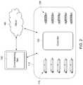
- a signage system 100includes a plurality of LED-based signs 110 , each having one or more corresponding LED signage drivers 115 .
- One or more controllers 120provide real-time monitoring and controlling four LEDs 116 (as depicted in FIG. 2 ) in each LED-based sign 110 .
- a commissioning application (“app”) 130commissions the one or more controllers 120 .
- An information system or databasewhich is housed remotely or on a cloud network or platform 140 , stores information received from and send commands to, the one or more controllers 120 related to the LED-based signs 110 .
- the signage system 100also includes at least one sensor 150 (e.g. a camera or the like).
- the LED-based signs 110can be found in the same or remote locations, spaced apart from each other. For example, one LED-based sign 110 on the system 100 can be in one state and another LED-based sign 110 can be located in a different state. That is, the LED-based signs 110 do not have to be physically co-located.
- the LED-based signs 110typically include a plurality of LEDs 116 , as depicted in FIG. 2 , and an associated driver 115 for driving the operation of the LEDs in each LED-based sign 110 .
- the LED driver 115can be designed to operate the LEDs 116 having different or same sets of electrical requirements, or any other suitable driver for the purposes set forth herein.
- the commissioning application 130initiates the monitoring and controlling of the LEDs 116 of the LED-based signs 110 .
- the commissioning application 130can be web-based or a browser-based interface accessible via a remote computer system e.g., a laptop, mobile device or personal computer (PC).
- a remote computer systeme.g., a laptop, mobile device or personal computer (PC).
- the commissioning application 130can also be an application contained completely on the device used to perform the commissioning process (e.g., an application running on a smart phone).
- the commissioning application 130can enable installers of the LED-based signs 110 to connect the controller 120 to a wireless data communications connection (e.g., local WiFi connection), as well as “push” parameter information, related to the LED-based signs 110 , to the controller 120 .
- This informationis pushed to the cloud-based information system on cloud network 140 or the commissioning application 130 at the user device. Separately, this information is also pushed by the commissioning application 130 to the cloud-based information system or cloud network 140 .
- the commissioning application 130can communicate with the controller(s) 120 directly over a communication network (e.g., Internet or WiFi) or via the information system on the cloud network 140 .
- a communication networke.g., Internet or WiFi
- the present inventionis not so limited and can include any number of controllers 120 , as necessary.
- the number of controllers 120corresponds to the number of LED-based signs 110 .
- a usercan access the commissioning application 130 and send a signal to the controller 120 of each LED-based sign 110 , requesting parameter information corresponding to the LED-based sign 110 .
- the usercan access the parameters from a user interface in the cloud network 140 .
- the parameters to be transmitted via the controller 120 , at the LED-based sign 110can include one or more of: status of LED signage driver 115 ; status of LEDs 116 in an LED-based sign 110 ; electrical parameters of an LED-based sign 110 (e.g., present current, voltage, and/or power status); controller 120 status; location of the LED-based sign 110 ; elevation or height of the LED-based sign 110 ; and overall LED-based sign 110 status.
- the controller 120can be disposed within the LED-based sign 110 and in electrical communication with a plurality of LEDs 116 .
- the controller 120can be configured to monitor a status of the LEDs 116 and control the LEDs 116 in real-time.
- the controller 120can also transmit status information to, and receive instructions from, the commissioning application 130 as depicted in FIG. 1 .
- This communicationcan occur via a communication network (e.g., WiFi) or via the cloud network 140 and provides for monitoring and controlling the LEDs 116 of the LED-based sign 110 .
- a communication networke.g., WiFi
- the controller 120can monitor and control the above-mentioned parameters and transfer related parameter data to the cloud-based information system on cloud network 140 .
- the controller 120can also transfer related parameter data directly to the commissioning application 130 , via the cloud-based information system on cloud network 140 . Details regarding the controller 120 will be discussed below with reference to FIG. 3 .
- FIG. 3is a block diagram illustrating the controller of the system shown in FIGS. 1 and 2 that can be implemented within one or more embodiments of the present invention.
- each controller 120can comprise one or more microcontrollers 122 , and an internal power supply interface 124 to be connected with the power supply of the LED-based sign 110 .
- Each controller 120can also include an amplifier 126 , an LED dimming module 127 , an Ethernet module/interface 128 , a WiFi module/interface 129 , or monitoring circuits (not shown).
- Each controller 120can include one or more communications modules which may be implemented as, but not limited to, an Ethernet module/interface 128 , WiFi module/interface 129 .
- the controller 120main be connected to a plurality of sensors 150 as depicted in FIG. 1 .
- the sensors 150can be disposed on the controller 120 , and/or external to the controller 120 .
- the plurality of sensors 150can include e.g., lights sensors, vibration sensors, humidity sensors, or temperature sensors to obtain further parameter information associated with the LED-based sign 110 .
- FIG. 4is a flow diagram illustrating an exemplary method 400 for remotely controlling the LED-based sign 110 within one or more of the embodiments.
- the method 400begins at operation 410 , where a plurality of LED-based signs are provided, each having one or more corresponding LED signage drivers.
- the method 400continues at operation 420 , where a commissioning application at a user device, commissions one or more controllers for monitoring and controlling the LEDs in the LED-based sign.
- the one or more controllersperform real-time monitoring and controlling of the LEDs in the LED-based sign by sensing, via a sensor in communication with the one or more controllers, status information of the LEDs. From operation 430 , the process continues to operation 440 where the status information is transmitted to the information system or cloud database which is housed remotely or on the cloud network, and/or directly to the commissioning application at the user device.
- the system 100can provide a user with diagnostics on the condition of a signage system.
- the system 100can also identify one or more faults in the signage that may occur throughout its lifecycle, an example of which is depicted in FIG. 5 .
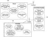
- FIG. 5is a schematic illustrating an example of use of the system 100 of FIG. 1 , implementable within the embodiments.
- an installercan display and configure new and existing signage systems and create a digital representation of signage systems in the cloud.
- the cloud-based information system on the cloud network 140can monitor and diagnose the signage systems.
- the cloud-based information system on the cloud network 140can also track service of life of the LED drivers 115 , display failures via a map, issue system and/or component failure alarms and other preemptive warnings/alarm messages. For example, the system can issue warnings based on historical failure data obtained via the controllers 120 at the LED-based signs 110 .
- the controllers 120can detect anomalies, monitor the signage system components and monitor interactions with other components.
- the controllers 120can also receive controller configuration and reconfigure themselves and send the parameter information to the cloud-based information system and/or the cloud network.
- the system 100is able to perform diagnostics on the data obtained from the controllers 120 , such as faults in the LED-based signs 110 .
- faultscan include, but are not limited to, one or more of LED light intensity, LED driver failure, LED module failure, electric shock hazard, potential fire, ice/snow build-up, flashing sign, extreme wind, or earthquake detection; or the like.
- diagnosticsOnce diagnostics have been performed, a user of the system 100 may then be notified of a complete status of the signage system.
- notificationsmay be configurable, and may be in the form of text message, e-mail, web report, or visual indicators, or the like.
- Wireless communicationmay comprise one or more of Bluetooth, Wi-Fi, LTE, ZigBee, 6 lowpan; or the like.
- Wired communicationmay comprise one or more of Ethernet or Fibre Optics, or the like.
- FIG. 6is a schematic illustrating a detailed example of usage of the system of FIG. 1 in accordance with the embodiments.
- the controller 120can further obtain driver configuration information from the cloud network 140 .
- the controller 120can also authenticate with the cloud and authenticate/accept the commissioning (e.g., phone) application connection. Additionally, it can act as a web client, monitor ports for data, and commission a physical reset button. The commissioning reset button resets the controller 120 to a factory state when pressed.
- the controller 120can also include a configuration storage.
- the commissioning application 130can illustrate drivers 115 to be changed, confirm controller configuration, and tell the information system on the cloud network 140 to reset the controller 120 .
- the commissioning application 130can also authenticate with the cloud system or network 140 , create/edit assets in the information system on the cloud network 140 , read controller information (e.g., barcode info), scan driver 115 barcodes, and send driver 115 configuration to the controller 120 .
- controller informatione.g., barcode info
- scan driver 115 barcodese.g., scan driver 115 barcodes
- the cloud system or network 140can create customer accounts, display locations and details of the LED-based signs 110 (i.e., assets), reset controller configuration, perform client creation and authentication, track service life of drivers and perform dimming of the LEDs 116 via the drivers 115 .
- the controller 120dims the LEDs 116 based on the dimming schedule.
- the dimming schedulemay be pre-configured on the device or it may be received from the cloud network 140 or commissioning application 130 .
- the present inventioncan permit a user to commission, monitor, control, and maintain signage applications.
- an ability to diagnose and detect live datawould allow users to identify faults at an appropriate time, in order to reduce time needed to repair, as well as potentially reduce system down-time. Having such an ability may provide flexibility to schedule preventative maintenance.
- the disclosed systemmay provide its user with an ability to identify faults down to the individual component; for example, a fault in an individual LED signage driver in a given sign.
- One possible technical advantageincludes the ability to detect, identify, and prevent faults within an entire signage system, from a location which is remote from the signs.
- the present disclosuremay allow a failure to be determined prior to arrival of a technician, such that the required replacement components can be purchased immediately and brought to the site of failure on the first trip of the technician. If the data from the signage system shows signs of future failure, selective preventative maintenance is also now an option.
Landscapes
- Engineering & Computer Science (AREA)
- Physics & Mathematics (AREA)
- Theoretical Computer Science (AREA)
- General Physics & Mathematics (AREA)
- Business, Economics & Management (AREA)
- Computer Hardware Design (AREA)
- Human Resources & Organizations (AREA)
- Entrepreneurship & Innovation (AREA)
- Strategic Management (AREA)
- Tourism & Hospitality (AREA)
- Quality & Reliability (AREA)
- General Business, Economics & Management (AREA)
- Operations Research (AREA)
- Marketing (AREA)
- Economics (AREA)
- Circuit Arrangement For Electric Light Sources In General (AREA)
Abstract
Description
Claims (21)
Priority Applications (1)
| Application Number | Priority Date | Filing Date | Title |
|---|---|---|---|
| US16/806,457US10991285B2 (en) | 2017-04-20 | 2020-03-02 | Cloud-based remote diagnostics for smart signage |
Applications Claiming Priority (3)
| Application Number | Priority Date | Filing Date | Title |
|---|---|---|---|
| US201762488019P | 2017-04-20 | 2017-04-20 | |
| US15/726,656US20180308403A1 (en) | 2017-04-20 | 2017-10-06 | Cloud-based remote diagnostics for smart signage |
| US16/806,457US10991285B2 (en) | 2017-04-20 | 2020-03-02 | Cloud-based remote diagnostics for smart signage |
Related Parent Applications (1)
| Application Number | Title | Priority Date | Filing Date |
|---|---|---|---|
| US15/726,656ContinuationUS20180308403A1 (en) | 2017-04-20 | 2017-10-06 | Cloud-based remote diagnostics for smart signage |
Publications (2)
| Publication Number | Publication Date |
|---|---|
| US20200273389A1 US20200273389A1 (en) | 2020-08-27 |
| US10991285B2true US10991285B2 (en) | 2021-04-27 |
Family
ID=63854115
Family Applications (2)
| Application Number | Title | Priority Date | Filing Date |
|---|---|---|---|
| US15/726,656AbandonedUS20180308403A1 (en) | 2017-04-20 | 2017-10-06 | Cloud-based remote diagnostics for smart signage |
| US16/806,457ActiveUS10991285B2 (en) | 2017-04-20 | 2020-03-02 | Cloud-based remote diagnostics for smart signage |
Family Applications Before (1)
| Application Number | Title | Priority Date | Filing Date |
|---|---|---|---|
| US15/726,656AbandonedUS20180308403A1 (en) | 2017-04-20 | 2017-10-06 | Cloud-based remote diagnostics for smart signage |
Country Status (1)
| Country | Link |
|---|---|
| US (2) | US20180308403A1 (en) |
Families Citing this family (1)
| Publication number | Priority date | Publication date | Assignee | Title |
|---|---|---|---|---|
| CN109584765A (en)* | 2019-01-23 | 2019-04-05 | 上海窗魅光学科技有限公司 | Realize the method and its system of LED display fault detection |
Citations (15)
| Publication number | Priority date | Publication date | Assignee | Title |
|---|---|---|---|---|
| US6166496A (en)* | 1997-08-26 | 2000-12-26 | Color Kinetics Incorporated | Lighting entertainment system |
| US6292901B1 (en)* | 1997-08-26 | 2001-09-18 | Color Kinetics Incorporated | Power/data protocol |
| US20050038326A1 (en)* | 2003-05-30 | 2005-02-17 | Michael Mathur | System, device, and method for remote monitoring and servicing |
| US20070159421A1 (en)* | 2006-01-10 | 2007-07-12 | Powerdsine, Ltd. | Secondary Side Post Regulation for LED Backlighting |
| US20090093688A1 (en)* | 2003-05-30 | 2009-04-09 | Michael Mathur | System, Device, and Method for Remote Monitoring and Servicing |
| US20090322800A1 (en)* | 2008-06-25 | 2009-12-31 | Dolby Laboratories Licensing Corporation | Method and apparatus in various embodiments for hdr implementation in display devices |
| US20100026190A1 (en)* | 2008-07-29 | 2010-02-04 | StarChips Technology Inc. | Led driver circuit and the method thereof |
| US20120274596A1 (en)* | 2011-07-11 | 2012-11-01 | Ludwig Lester F | Use of organic light emitting diode (oled) displays as a high-resolution optical tactile sensor for high dimensional touchpad (hdtp) user interfaces |
| US20150035437A1 (en)* | 2013-08-05 | 2015-02-05 | Peter J. Panopoulos | Led lighting system |
| US20150130351A1 (en)* | 2013-11-08 | 2015-05-14 | Zachary Leonid Braunstein | Apparatus Intelligent Parallel View LED Light, Methods of Configuration and Controls |
| US20150294603A1 (en)* | 2013-08-12 | 2015-10-15 | Zachary Leonid Braunstein | Apparatus Intelligent Illuminated Sign, Methods of Configuration and Controls |
| US20160224306A1 (en)* | 2015-01-30 | 2016-08-04 | Cirrus Systems, Inc. | Modular Display System with Automatic Locating Features |
| US20160275835A1 (en)* | 2013-09-26 | 2016-09-22 | Xi'an Novastar Tech Co., Ltd. | Led display unit board, led display screen control card and led display screen system |
| US20170223807A1 (en)* | 2006-03-28 | 2017-08-03 | Wireless Environment, Llc. | Cloud connected lighting system |
| US20180227998A1 (en)* | 2017-02-03 | 2018-08-09 | Ledvance Gmbh | Commissioning, decommissioning and testing of a smart sensor-driven LED lighting system without gateway |
- 2017
- 2017-10-06USUS15/726,656patent/US20180308403A1/ennot_activeAbandoned
- 2020
- 2020-03-02USUS16/806,457patent/US10991285B2/enactiveActive
Patent Citations (15)
| Publication number | Priority date | Publication date | Assignee | Title |
|---|---|---|---|---|
| US6292901B1 (en)* | 1997-08-26 | 2001-09-18 | Color Kinetics Incorporated | Power/data protocol |
| US6166496A (en)* | 1997-08-26 | 2000-12-26 | Color Kinetics Incorporated | Lighting entertainment system |
| US20050038326A1 (en)* | 2003-05-30 | 2005-02-17 | Michael Mathur | System, device, and method for remote monitoring and servicing |
| US20090093688A1 (en)* | 2003-05-30 | 2009-04-09 | Michael Mathur | System, Device, and Method for Remote Monitoring and Servicing |
| US20070159421A1 (en)* | 2006-01-10 | 2007-07-12 | Powerdsine, Ltd. | Secondary Side Post Regulation for LED Backlighting |
| US20170223807A1 (en)* | 2006-03-28 | 2017-08-03 | Wireless Environment, Llc. | Cloud connected lighting system |
| US20090322800A1 (en)* | 2008-06-25 | 2009-12-31 | Dolby Laboratories Licensing Corporation | Method and apparatus in various embodiments for hdr implementation in display devices |
| US20100026190A1 (en)* | 2008-07-29 | 2010-02-04 | StarChips Technology Inc. | Led driver circuit and the method thereof |
| US20120274596A1 (en)* | 2011-07-11 | 2012-11-01 | Ludwig Lester F | Use of organic light emitting diode (oled) displays as a high-resolution optical tactile sensor for high dimensional touchpad (hdtp) user interfaces |
| US20150035437A1 (en)* | 2013-08-05 | 2015-02-05 | Peter J. Panopoulos | Led lighting system |
| US20150294603A1 (en)* | 2013-08-12 | 2015-10-15 | Zachary Leonid Braunstein | Apparatus Intelligent Illuminated Sign, Methods of Configuration and Controls |
| US20160275835A1 (en)* | 2013-09-26 | 2016-09-22 | Xi'an Novastar Tech Co., Ltd. | Led display unit board, led display screen control card and led display screen system |
| US20150130351A1 (en)* | 2013-11-08 | 2015-05-14 | Zachary Leonid Braunstein | Apparatus Intelligent Parallel View LED Light, Methods of Configuration and Controls |
| US20160224306A1 (en)* | 2015-01-30 | 2016-08-04 | Cirrus Systems, Inc. | Modular Display System with Automatic Locating Features |
| US20180227998A1 (en)* | 2017-02-03 | 2018-08-09 | Ledvance Gmbh | Commissioning, decommissioning and testing of a smart sensor-driven LED lighting system without gateway |
Also Published As
| Publication number | Publication date |
|---|---|
| US20180308403A1 (en) | 2018-10-25 |
| US20200273389A1 (en) | 2020-08-27 |
Similar Documents
| Publication | Publication Date | Title |
|---|---|---|
| US20180024598A1 (en) | Server rack for improved data center management | |
| US11805591B2 (en) | Emergency lighting system with integrated testing and reporting functionality | |
| WO2018036554A1 (en) | Apparatus fault detection system, and fault detection device | |
| US9224122B2 (en) | Outdoor device management system | |
| US11749096B2 (en) | Event device operation | |
| CN104883379A (en) | Electric appliance equipment fault alarming method and system, and social network server | |
| CN105302111A (en) | Method for inquiring fault of power terminal via two-dimensional code | |
| US11579602B2 (en) | Method for commissioning and maintenance of alarm systems | |
| CN105279919A (en) | Electricity utilization information acquiring system | |
| US10991285B2 (en) | Cloud-based remote diagnostics for smart signage | |
| JP3184828U (en) | Monitoring equipment for photovoltaic power generation facilities | |
| CN111371180A (en) | Substation patrol supervision and data analysis system | |
| KR101700697B1 (en) | Wireless remote monitoring and control system and its method | |
| CN106710651B (en) | A kind of method and system for showing nuclear power station center accident condition transition | |
| KR101108827B1 (en) | Equipment uptime and status acquisition method and system | |
| WO2021005542A1 (en) | Method and device for fault diagnosis and rectification for an industrial controller | |
| EP3130200B1 (en) | Wireless configuration and diagnostics of airfield lighting fixtures | |
| JP5844666B2 (en) | HART communication compatible equipment | |
| Thilagaraj et al. | IoT-based Cable Fault Detector with GSM and GPS Module using Arduino | |
| AU2018252445B2 (en) | Communication adapter and connection test run method therefor | |
| KR20160099902A (en) | Part Life Management System | |
| JP2014174947A (en) | Plant maintenance support system and plant maintenance support method using the system | |
| KR20230038961A (en) | Work monitoring system | |
| JP7390457B1 (en) | Lighting control/condition monitoring system | |
| KR101733685B1 (en) | A charge discharge control system |
Legal Events
| Date | Code | Title | Description |
|---|---|---|---|
| FEPP | Fee payment procedure | Free format text:ENTITY STATUS SET TO UNDISCOUNTED (ORIGINAL EVENT CODE: BIG.); ENTITY STATUS OF PATENT OWNER: LARGE ENTITY | |
| AS | Assignment | Owner name:GE LIGHTING SOLUTIONS, LLC, OHIO Free format text:ASSIGNMENT OF ASSIGNORS INTEREST;ASSIGNORS:RANA, SHAHZIL;RICHARD, JEAN-FRANCOIS;PETRESCU, ALIN IONUT;AND OTHERS;SIGNING DATES FROM 20170921 TO 20171003;REEL/FRAME:051990/0081 Owner name:CURRENT LIGHTING SOLUTIONS, LLC, OHIO Free format text:CHANGE OF NAME;ASSIGNOR:GE LIGHTING SOLUTIONS, LLC;REEL/FRAME:052075/0229 Effective date:20190401 | |
| STPP | Information on status: patent application and granting procedure in general | Free format text:NON FINAL ACTION MAILED | |
| STPP | Information on status: patent application and granting procedure in general | Free format text:RESPONSE TO NON-FINAL OFFICE ACTION ENTERED AND FORWARDED TO EXAMINER | |
| STPP | Information on status: patent application and granting procedure in general | Free format text:NOTICE OF ALLOWANCE MAILED -- APPLICATION RECEIVED IN OFFICE OF PUBLICATIONS | |
| STPP | Information on status: patent application and granting procedure in general | Free format text:PUBLICATIONS -- ISSUE FEE PAYMENT RECEIVED | |
| STPP | Information on status: patent application and granting procedure in general | Free format text:PUBLICATIONS -- ISSUE FEE PAYMENT VERIFIED | |
| STCF | Information on status: patent grant | Free format text:PATENTED CASE | |
| AS | Assignment | Owner name:ALLY BANK, AS COLLATERAL AGENT, NEW YORK Free format text:SECURITY AGREEMENT;ASSIGNORS:HUBBELL LIGHTING, INC.;LITECONTROL CORPORATION;CURRENT LIGHTING SOLUTIONS, LLC;AND OTHERS;REEL/FRAME:058982/0844 Effective date:20220201 | |
| AS | Assignment | Owner name:ATLANTIC PARK STRATEGIC CAPITAL FUND, L.P., AS COLLATERAL AGENT, NEW YORK Free format text:SECURITY INTEREST;ASSIGNORS:HUBBELL LIGHTING, INC.;LITECONTROL CORPORATION;CURRENT LIGHTING SOLUTIONS, LLC;AND OTHERS;REEL/FRAME:059034/0469 Effective date:20220201 | |
| AS | Assignment | Owner name:ALLY BANK, AS COLLATERAL AGENT, NEW YORK Free format text:CORRECTIVE ASSIGNMENT TO CORRECT THE PATENT NUMBER 10841994 TO PATENT NUMBER 11570872 PREVIOUSLY RECORDED ON REEL 058982 FRAME 0844. ASSIGNOR(S) HEREBY CONFIRMS THE SECURITY AGREEMENT;ASSIGNORS:HUBBELL LIGHTING, INC.;LITECONTROL CORPORATION;CURRENT LIGHTING SOLUTIONS, LLC;AND OTHERS;REEL/FRAME:066355/0455 Effective date:20220201 | |
| AS | Assignment | Owner name:ATLANTIC PARK STRATEGIC CAPITAL FUND, L.P., AS COLLATERAL AGENT, NEW YORK Free format text:CORRECTIVE ASSIGNMENT TO CORRECT THE PATENT NUMBER PREVIOUSLY RECORDED AT REEL: 059034 FRAME: 0469. ASSIGNOR(S) HEREBY CONFIRMS THE SECURITY INTEREST;ASSIGNORS:HUBBELL LIGHTING, INC.;LITECONTROL CORPORATION;CURRENT LIGHTING SOLUTIONS, LLC;AND OTHERS;REEL/FRAME:066372/0590 Effective date:20220201 | |
| MAFP | Maintenance fee payment | Free format text:PAYMENT OF MAINTENANCE FEE, 4TH YEAR, LARGE ENTITY (ORIGINAL EVENT CODE: M1551); ENTITY STATUS OF PATENT OWNER: LARGE ENTITY Year of fee payment:4 |