US10989725B2 - Method of operating a laboratory sample distribution system, laboratory sample distribution system, and laboratory automation system - Google Patents
Method of operating a laboratory sample distribution system, laboratory sample distribution system, and laboratory automation systemDownload PDFInfo
- Publication number
- US10989725B2 US10989725B2US15/988,637US201815988637AUS10989725B2US 10989725 B2US10989725 B2US 10989725B2US 201815988637 AUS201815988637 AUS 201815988637AUS 10989725 B2US10989725 B2US 10989725B2
- Authority
- US
- United States
- Prior art keywords
- transport plane
- sample container
- categorized
- transport
- waypoint
- Prior art date
- Legal status (The legal status is an assumption and is not a legal conclusion. Google has not performed a legal analysis and makes no representation as to the accuracy of the status listed.)
- Active, expires
Links
Images


Classifications
- G—PHYSICS
- G01—MEASURING; TESTING
- G01N—INVESTIGATING OR ANALYSING MATERIALS BY DETERMINING THEIR CHEMICAL OR PHYSICAL PROPERTIES
- G01N35/00—Automatic analysis not limited to methods or materials provided for in any single one of groups G01N1/00 - G01N33/00; Handling materials therefor
- G01N35/02—Automatic analysis not limited to methods or materials provided for in any single one of groups G01N1/00 - G01N33/00; Handling materials therefor using a plurality of sample containers moved by a conveyor system past one or more treatment or analysis stations
- G01N35/04—Details of the conveyor system
- B—PERFORMING OPERATIONS; TRANSPORTING
- B65—CONVEYING; PACKING; STORING; HANDLING THIN OR FILAMENTARY MATERIAL
- B65G—TRANSPORT OR STORAGE DEVICES, e.g. CONVEYORS FOR LOADING OR TIPPING, SHOP CONVEYOR SYSTEMS OR PNEUMATIC TUBE CONVEYORS
- B65G35/00—Mechanical conveyors not otherwise provided for
- B—PERFORMING OPERATIONS; TRANSPORTING
- B65—CONVEYING; PACKING; STORING; HANDLING THIN OR FILAMENTARY MATERIAL
- B65G—TRANSPORT OR STORAGE DEVICES, e.g. CONVEYORS FOR LOADING OR TIPPING, SHOP CONVEYOR SYSTEMS OR PNEUMATIC TUBE CONVEYORS
- B65G54/00—Non-mechanical conveyors not otherwise provided for
- B65G54/02—Non-mechanical conveyors not otherwise provided for electrostatic, electric, or magnetic
- G—PHYSICS
- G01—MEASURING; TESTING
- G01N—INVESTIGATING OR ANALYSING MATERIALS BY DETERMINING THEIR CHEMICAL OR PHYSICAL PROPERTIES
- G01N35/00—Automatic analysis not limited to methods or materials provided for in any single one of groups G01N1/00 - G01N33/00; Handling materials therefor
- G01N35/00584—Control arrangements for automatic analysers
- B—PERFORMING OPERATIONS; TRANSPORTING
- B65—CONVEYING; PACKING; STORING; HANDLING THIN OR FILAMENTARY MATERIAL
- B65G—TRANSPORT OR STORAGE DEVICES, e.g. CONVEYORS FOR LOADING OR TIPPING, SHOP CONVEYOR SYSTEMS OR PNEUMATIC TUBE CONVEYORS
- B65G2201/00—Indexing codes relating to handling devices, e.g. conveyors, characterised by the type of product or load being conveyed or handled
- B65G2201/02—Articles
- B65G2201/0235—Containers
- B65G2201/0261—Puck as article support
- G—PHYSICS
- G01—MEASURING; TESTING
- G01N—INVESTIGATING OR ANALYSING MATERIALS BY DETERMINING THEIR CHEMICAL OR PHYSICAL PROPERTIES
- G01N35/00—Automatic analysis not limited to methods or materials provided for in any single one of groups G01N1/00 - G01N33/00; Handling materials therefor
- G01N35/02—Automatic analysis not limited to methods or materials provided for in any single one of groups G01N1/00 - G01N33/00; Handling materials therefor using a plurality of sample containers moved by a conveyor system past one or more treatment or analysis stations
- G01N35/04—Details of the conveyor system
- G01N2035/0401—Sample carriers, cuvettes or reaction vessels
- G01N2035/0406—Individual bottles or tubes
- G—PHYSICS
- G01—MEASURING; TESTING
- G01N—INVESTIGATING OR ANALYSING MATERIALS BY DETERMINING THEIR CHEMICAL OR PHYSICAL PROPERTIES
- G01N35/00—Automatic analysis not limited to methods or materials provided for in any single one of groups G01N1/00 - G01N33/00; Handling materials therefor
- G01N35/02—Automatic analysis not limited to methods or materials provided for in any single one of groups G01N1/00 - G01N33/00; Handling materials therefor using a plurality of sample containers moved by a conveyor system past one or more treatment or analysis stations
- G01N35/04—Details of the conveyor system
- G01N2035/046—General conveyor features
- G01N2035/0462—Buffers [FIFO] or stacks [LIFO] for holding carriers between operations
- G—PHYSICS
- G01—MEASURING; TESTING
- G01N—INVESTIGATING OR ANALYSING MATERIALS BY DETERMINING THEIR CHEMICAL OR PHYSICAL PROPERTIES
- G01N35/00—Automatic analysis not limited to methods or materials provided for in any single one of groups G01N1/00 - G01N33/00; Handling materials therefor
- G01N35/02—Automatic analysis not limited to methods or materials provided for in any single one of groups G01N1/00 - G01N33/00; Handling materials therefor using a plurality of sample containers moved by a conveyor system past one or more treatment or analysis stations
- G01N35/04—Details of the conveyor system
- G01N2035/046—General conveyor features
- G01N2035/0467—Switching points ("aiguillages")
- G01N2035/0472—Switching points ("aiguillages") for selective recirculation of carriers
- G—PHYSICS
- G01—MEASURING; TESTING
- G01N—INVESTIGATING OR ANALYSING MATERIALS BY DETERMINING THEIR CHEMICAL OR PHYSICAL PROPERTIES
- G01N35/00—Automatic analysis not limited to methods or materials provided for in any single one of groups G01N1/00 - G01N33/00; Handling materials therefor
- G01N35/02—Automatic analysis not limited to methods or materials provided for in any single one of groups G01N1/00 - G01N33/00; Handling materials therefor using a plurality of sample containers moved by a conveyor system past one or more treatment or analysis stations
- G01N35/04—Details of the conveyor system
- G01N2035/0474—Details of actuating means for conveyors or pipettes
- G01N2035/0477—Magnetic
Definitions
- the present disclosurerelates to a method of operating a laboratory sample distribution system, a laboratory sample distribution system, and a laboratory automation system.
- Laboratory sample distribution systemsare used in laboratory automation systems comprising a number of laboratory stations.
- the laboratory sample distribution systemcan be used in order to distribute sample containers between the laboratory stations and other equipment.
- sample container carriersare moved on a transport plane.
- a number of electro-magnetic actuatorsis arranged below the transport plane in order to move the sample container carriers.
- the laboratory sample distribution systemcan comprise a number of sample container carriers. Each of the sample container carriers can comprise at least one magnetically active device. Each of the sample container carriers can be configured to carry at least one sample container.
- the laboratory sample distribution systemcan also comprise a number of interconnected transport plane modules. Each of the transport plane modules can be configured to support a number of the sample container carriers.
- the laboratory sample distribution systemcan also comprise a number of electro-magnetic actuators. Below each transport plane module, a number of the electro-magnetic actuators can be stationary arranged in rows and columns.
- the electro-magnetic actuatorscan be configured to move a sample container carrier of the sample container carriers on top of the transport plane modules along a row of the rows or along a column of the columns by applying a magnetic move force to the sample container carrier.
- the methodcan comprise assigning at least one transport plane module of the transport plane modules to a route category. At least two traffic lanes can be formed on the route categorized transport plane module. The sample container carriers can be moved within each traffic lane in a given transport direction. The transport directions of the at least two traffic lanes can be opposite to each other. A change from one transport direction to the opposite transport direction cannot be possible for the sample container carriers moved on the route categorized transport plane module.
- the methodcan also comprise assigning at least one another transport plane module of the transport plane modules to a waypoint category. A change from one transport direction to the opposite transport direction can be enabled for the sample container carriers moved on the waypoint categorized transport plane module.
- FIG. 1illustrates schematically a perspective view of a laboratory automation system comprising a laboratory sample distribution system according to an embodiment of the present disclosure.
- FIG. 2illustrates a longitudinal section view of a sample container carrier of FIG. 1 according to an embodiment of the present disclosure.
- FIG. 3illustrates schematically transport plane modules of FIG. 1 assigned to a route category according to an embodiment of the present disclosure.
- FIG. 4illustrates schematically other route categorized transport plane modules according to an embodiment of the present disclosure.
- FIG. 5illustrates schematically other transport plane modules assigned to a route category and a transport plane module assigned to a waypoint category according to an embodiment of the present disclosure.
- FIG. 6illustrates schematically other route categorized transport plane modules and other waypoint categorized transport plane modules according to an embodiment of the present disclosure.
- FIG. 7illustrates schematically other route categorized transport plane modules and another waypoint categorized transport plane module according to an embodiment of the present disclosure.
- FIG. 8illustrates schematically other route categorized transport plane modules and another waypoint categorized transport plane module according to an embodiment of the present disclosure.
- FIG. 9illustrates schematically other route categorized transport plane modules and another waypoint categorized transport plane module according to an embodiment of the present disclosure.
- FIG. 10illustrates schematically other route categorized transport plane modules and another waypoint categorized transport plane module according to an embodiment of the present disclosure.
- FIG. 11illustrates schematically other route categorized transport plane modules and another waypoint categorized transport plane module according to an embodiment of the present disclosure.
- FIG. 12 aillustrates schematically another route categorized transport plane module with an erroneous electro-magnetic actuator below according to an embodiment of the present disclosure.
- FIG. 12 billustrates schematically the route categorized transport plane module of FIG. 12 a with reformed traffic lanes and a reformed buffer lane according to an embodiment of the present disclosure.
- FIG. 13 aillustrates schematically other route categorized transport plane modules with erroneous electro-magnetic actuators below according to an embodiment of the present disclosure.
- FIG. 13 billustrates schematically the route categorized transport plane modules of FIG. 13 a with reformed traffic lanes and reformed buffer lanes according to an embodiment of the present disclosure.
- FIG. 14 aillustrates schematically other route categorized transport plane modules with erroneous electro-magnetic actuators below according to an embodiment of the present disclosure.
- FIG. 14 billustrates schematically the route categorized transport plane modules of FIG. 14 a with reformed traffic lanes and reformed buffer lanes according to an embodiment of the present disclosure.
- FIG. 15illustrates schematically other transport plane modules assigned to a route category, other transport plane modules assigned to a waypoint category and other transport plane modules assigned to a laboratory station category according to an embodiment of the present disclosure.
- the laboratory sample distribution systemcan comprise a number (e.g., 2 to 2000) of sample container carriers.
- Each of the sample container carrierscan comprise at least one magnetically active device.
- each of the sample container carrierscan be configured to carry at least one sample container, in other words, one or more sample containers.
- the laboratory sample distribution systemcan comprise a number (e.g., 2 to 2000) of interconnected transport plane modules or parts.
- Each of the transport plane modulescan be configured to support or carry a number or some of the sample container carriers. In other words, the sample container carriers may simply be placed on the interconnected transport plane modules.
- the laboratory sample distribution systemcan comprise a number (e.g., 20 to 2000) of electro-magnetic actuators.
- a number or some of the electro-magnetic actuatorscan be stationary arranged in rows and columns.
- the electro-magnetic actuatorscan be configured to move a sample container carrier of the sample container carriers, in particular all, on top of the transport plane modules, in particular exclusively, along a row of the rows or along a column of the columns by applying a magnetic move force to the sample container carrier.
- the methodcan comprise assigning at least one transport plane module of the transport plane modules to a route category. At least two traffic, or transport, lanes can be formed on the route categorized transport plane module.
- the sample container carrierscan be moved within each traffic lane in a given transport direction, in particular, only in one transport direction.
- the transport directions of the at least two traffic lanescan be opposite to each other. A change from one transport direction to the opposite transport direction and vice versa—from the opposite transport direction to the one transport direction—, cannot be possible, disabled, prevented, prohibited or not allowed for the sample container carriers moved on the route categorized transport plane module.
- the methodcan also comprise assigning at least one another transport plane module of the transport plane modules to a waypoint category. A change from one transport direction to the opposite transport direction and vice versa can be enabled, possible or allowed for the sample container carriers moved on the waypoint categorized transport plane module.
- the sample containersmay be designed as tubes made of glass or transparent plastic and may have an opening at an upper end. Furthermore, the sample containers may be used to contain, store and transport samples such as blood samples, urine samples or chemical or medical samples, e.g., to be analyzed by a number of laboratory stations.
- transport plane modulemay denote that the number of transport plane modules may be embodied as separated constructional units and/or as subunits of, in particular only one, transport plane unit. In particular, the transport plane modules may be different from each other.
- the transport plane modulesmay be identically constructed.
- interconnectedmay denote that the transport plane modules may be interconnected, such that the sample container carriers may move from each of the transport plane modules directly or indirectly to each of the other modules.
- the interconnected transport plane modulesmay form a continuous transport plane, which may also be denoted as transport surface.
- the electro-magnetic actuatorsmay be solenoids surrounding ferromagnetic cores. Moreover, the electro-magnetic actuators may be driven or energized individually in order to generate or to provide a magnetic field. The magnetic field may interact with the magnetically active device of a respective sample container carrier. By the interaction, the electro-magnetic actuators may apply the magnetic move force to the sample container carrier. Hence, the sample container carrier may be translationally moved on the transport plane modules.
- the magnetically active device of the sample container carriermay be a permanent magnet. Alternatively, or additionally, an electro-magnet and/or any magnetically soft material may be used.
- the sample container carriersmay be configured to move in two dimensions on the transport plane modules. For that purpose, the rows and columns may be arranged in two dimensions such as, for example, quadratically.
- the electro-magnetic actuatorsmay be arranged in a plane substantially parallel to the transport plane modules.
- the assignment of at least one another transport plane module of the transport plane modules to a waypoint categorymay be performed after, at the same time as and/or before the assignment of at least one transport plane module of the transport plane modules to a route category.
- a respective traffic lanemay be defined by at least one row of the rows and/or at least one column of the columns.
- a width of the sample container carrier on the transport plane modulemay correspond to or be smaller than a width of the traffic lane.
- no direction changemay be possible on the route categorized transport plane module.
- the route categorized transport plane modulemay be physically constructed, such that a direction change may be physically possible, in particular it may be free of barriers for the sample container carriers, a direction change on the route categorized transport plane module may not be logically possible.
- the methodcan enable the control of the movements of the sample container carriers in a relative simple way such as, for example, on the at least one route categorized transport plane module. Furthermore, the method may reduce or prevent deadlock situations, in which sample container carriers may block each other. Moreover, the method may reduce or prevent a risk of collisions between sample container carriers. Hence, the method may enable a high distribution performance at reduced transport space required.
- a change areacan be formed on the waypoint categorized transport plane module.
- the change areacan be configured to receive a sample container carrier of the sample container carriers from one traffic lane with a given transport direction and to pass, to forward, to transfer or to transmit the received sample container carrier to another traffic lane with an opposite transport direction and vice versa.
- the sample container carriermay wait, until the another traffic lane is free. This may allow less or no sample container carriers on the one traffic lane, waiting for a direction change.
- the change areamay be different from the traffic lanes.
- At least two traffic lanescan be formed on the waypoint categorized transport plane module.
- the sample container carrierscan be moved within each traffic lane in a given transport direction.
- the transport directions of the at least two traffic lanescan be opposite to each other.
- the change areacan be arranged in between the two traffic lanes at their sides such as, for example, directly next to one or both of them.
- the change areacan be configured to receive a sample container carrier of the sample container carriers from the one traffic lane formed on the waypoint categorized transport plane module and to pass the received sample container carrier to the another traffic lane formed on the waypoint categorized transport plane module and vice versa. This can enable a direction change at reduced transport space required on a single transport plane module.
- the at least two traffic lanes formed on the waypoint categorized transport plane modulemay be in extension of the at least two traffic lanes formed on the route categorized transport plane module.
- the change areacan be completely surrounded by, for example, the at least, two traffic lanes formed on the waypoint categorized transport plane module. This may allow to receive and/or to pass the sample container carrier from and/or to all sides of the change area.
- the sample container carrierscan be moved within the change area such as, for example, only in a single direction. Hence, there may be no opposing traffic within the change area. Thereby, this may enable to reduce or to prevent deadlock situations and/or a risk of collisions within the change area.
- a change within the change areacan be possible only from the one traffic lane with a given transport direction to the another traffic lane with an opposite transport direction and not from the another traffic lane to the one traffic lane.
- Thiscan enable control of the movements of the sample container carriers within the change area in a relative simple way. Hence, this may enable a high throughout through the change area.
- the sample container carrierscan be moved within the change area in a circle. This may enable a continuous traffic flow such as, for example, around a center of the change area.
- an enter areacan be formed on the waypoint categorized transport plane module.
- the enter areacan be arranged in between the change area and a traffic lane of the traffic lanes directing to the change area such as, for example, in extension of the traffic lane.
- the enter areacan be configured to receive a sample container carrier of the sample container carriers from the traffic lane and to pass the received sample container carrier to the change area, when there is no cross traffic within the change area blocking the sample container carrier. This can reduce or prevent deadlock situations and/or a risk of collisions within the change area and/or the enter area.
- next to a traffic lane of the traffic lanesat least one buffer lane can be formed on the route categorized transport plane module and/or the waypoint categorized transport plane module.
- Each of the buffer lanescan be configured to receive a number of the sample container carriers from the corresponding traffic lane, to buffer the received sample container carriers, and to return the buffered sample container carriers to the corresponding traffic lane.
- Thiscan buffer sample container carriers, e.g., if the sample container carriers are waiting for further movement over the transport plane module/s and/or if a sample container and/or a sample comprised in the sample container carrier waits for further processing.
- the buffer lanemay buffer empty sample container carriers.
- the buffer lanemay be configured to buffer or to store a variable number (e.g., 2 to 500) of sample container carriers.
- next to each traffic lanea buffer lane may be formed.
- the traffic lanes and/or the buffer lanes and/or the change area and/or the enter area formed on the route categorized transport plane module and/or on the waypoint categorized transport plane modulecan be symmetrically arranged. This may control the movements of the sample container carriers in a relative simple way. Additionally, or alternatively this may require relatively low transport space.
- the lanes and/or the areasmay be mirror-symmetrically and/or rotationally-symmetrically arranged.
- the methodcan comprise checking the number of electro-magnetic actuators for errors and forming and/or reforming the traffic lanes and/or the buffer lanes and/or the change area and/or the enter area, and in one embodiment only, above error-free electro-magnetic actuators. This can enable a use of the laboratory sample distribution in spite of erroneous or defective electro-magnetic actuators.
- the methodcan comprise assigning at least three transport plane modules of the transport plane modules to a laboratory station category. Handling a sample container carrier of the sample container carriers, handling a sample container and/or handling a sample by a laboratory station can be enabled on each of the laboratory station categorized transport plane modules.
- the methodcan also comprise assigning at least four transport plane modules to the waypoint category. To each of the laboratory station categorized transport plane modules, one of the waypoint categorized transport plane modules can be assigned or arranged such as, for example, directly next to it.
- the methodcan also comprise assigning at least three transport plane modules to the route category. In between each two of the waypoint categorized transport plane modules, at least one of the route categorized transport plane modules can be arranged, for example, directly next to one or both of them.
- the methodcan also comprise determining a route for a movement of the sample container carrier from one laboratory station categorized transport plane module to another laboratory station categorized transport plane module by listing the waypoint categorized transport plane modules and their order in between them.
- the methodcan also comprise moving the sample container carrier from one waypoint categorized transport plane module to the next one according to the determined list. This can determine the route in a relative simple way.
- thismay enable a rerouting or redirecting of the sample container carrier in a relative simple way such as, for example, to another target laboratory station, e.g., if a primary target laboratory station is offline, in particular it may have an error or be maintained, if an electro-magnetic actuator is erroneous and/or if a traffic jam occurs on the route to the primary target laboratory station.
- a laboratory sample distribution systemcan comprise the number of sample container carriers, the number of interconnected transport plane modules, and the number of electro-magnetic actuators.
- the laboratory sample distribution systemcan comprise a control device.
- the control deviceis adapted or configured to perform the method as described above.
- control devicemay be configured to assign at least one transport plane module of the transport plane modules to a route category, wherein at least two traffic lanes can be formed on the route categorized transport plane module, wherein the sample container carriers can be moved within each traffic lane in a given transport direction, wherein the transport directions of the at least two traffic lanes can be opposite to each other and wherein a change from one transport direction to the opposite transport direction may not be possible for the sample container carriers moved on the route categorized transport plane module.
- control devicemay be configured to assign at least one another transport plane module of the transport plane modules to a waypoint category, wherein a change from one transport direction to the opposite transport direction can be enabled for the sample container carriers moved on the waypoint categorized transport plane module.
- control devicemay be configured to control the movements of the sample container carriers on top of the transport plane modules by driving or energizing the electro-magnetic actuators, such that the sample container carriers can move simultaneously and independent from one another along desired transport paths such as, for example, individual transport paths.
- the control devicemay comprise a personal computer (PC), a server, a processor, and/or a memory.
- the control devicemay comprise sub-control devices, wherein to each transport plane module one of the sub-control devices may be assigned or arranged, wherein each of the sub-control devices may be configured to control the movements of the sample container carriers on top of the respective transport plane module.
- n times n electro-magnetic actuators of the electro-magnetic actuatorscan be stationary arranged in n rows and in n columns.
- ncan be an integer and greater than three. In one embodiment, n may be greater than five and in another embodiment, exactly six.
- electro-magnetic actuatorsmay be, in one embodiment, equidistantly spaced, stationary arranged in n rows and in n columns such as, for example, quadratically, wherein in each second row in each second position there may be no electro-magnetic actuator or in each center of a quadrat formed by corresponding electro-magnetic actuators no electro-magnetic actuator may be arranged and wherein n can be an integer and greater than three.
- EP 3 070 479 A1which content is incorporated into this document by reference.
- EP 2 995 958 A1which content is incorporated into this document by reference.
- a laboratory automation systemcan comprise a number of laboratory stations such as, for example, a number of pre-analytical, analytical and/or post-analytical laboratory stations.
- the laboratory automation systemcan comprise a laboratory sample distribution system as described above.
- the laboratory sample distribution systemcan be configured to distribute the number sample container carriers and/or sample containers between the laboratory stations.
- the laboratory stationsmay be arranged adjacent or directly next to the laboratory sample distribution system.
- Pre-analytical laboratory stationsmay be configured to perform any kind of pre-processing of samples, sample containers and/or sample container carriers.
- Analytical laboratory stationsmay be configured to use a sample or part of the sample and a reagent to generate a measuring signal, the measuring signal indicating if and in which concentration, if any, an analyte exists.
- Post-analytical laboratory stationsmay be configured to perform any kind of post-processing of samples, sample containers and/or sample container carriers.
- the pre-analytical, analytical and/or post-analytical laboratory stationsmay comprise at least one of a decapping station, a recapping station, an aliquot station, a centrifugation station, an archiving station, a pipetting station, a sorting station, a sample container type identification station, a sample quality determining station, an add-on buffer station, a liquid level detection station, a sealing/desealing station, a pushing station, a belt station, a conveying system station and/or a gripper station for moving the sample container to or from the sample container carrier.
- FIG. 1schematically shows a laboratory automation system 10 .
- the laboratory automation system 10can comprise a number of laboratory stations 20 , for example, pre-analytical, analytical and/or post-analytical laboratory stations. In the shown embodiment, only two laboratory stations 20 are depicted. Self-evidently, the laboratory automation system 10 may comprise more than two laboratory stations 20 .
- the laboratory automation system 10can comprise a laboratory sample distribution system 100 configured to distribute a number of sample container carriers 110 and/or sample containers 120 between the laboratory stations 20 .
- the laboratory stations 20can be arranged directly next to the laboratory sample distribution system 100 .
- the laboratory sample distribution system 100can comprise the number of sample container carriers 110 .
- the laboratory sample distribution system 100may comprise a large number of sample container carriers 110 , e.g., one hundred to several thousands of sample container carriers.
- Each of the sample container carriers 110can comprise a magnetically active device 115 , as depicted in FIG. 2 , which is, in this embodiment, a single permanent magnet.
- each of the sample container carriers 110can be configured to carry one of the sample containers 120 .
- the laboratory sample distribution system 100can comprise a number of interconnected transport plane modules 130 a , 130 b , 130 c .
- Each of the transport plane modules 130 a , 130 b , 130 ccan be configured to support a number of said sample container carriers 110 .
- the laboratory sample distribution system 100can comprise a number of electro-magnetic actuators 140 .
- the electro-magnetic actuators 140can be implemented as solenoids, each having a solid ferromagnetic core 145 .
- a number of the electro-magnetic actuators 140can be stationary arranged in rows 150 and columns 160 such as, for example, quadratically in a plane substantially parallel to the transport plane modules.
- the electro-magnetic actuators 140can be configured to move a sample container carrier 110 of the sample container carriers on top of the transport plane modules 130 a , 130 b , 130 c along a row 150 of the rows or along a column 160 of the columns by applying a magnetic move force to the sample container carrier 110 .
- the electro-magnetic actuators 140 and the rows 150 and columns 160can form logical fields on the transport plane modules 130 a , 130 b , 130 c , as depicted in FIGS. 1 and 3-14 b.
- the laboratory sample distribution system 100can comprise a control device 170 .
- the control device 170can be configured to perform a method as described below.
- the control device 170can be configured to control the movements of the sample container carriers 110 on top of the transport plane modules 130 a , 130 b , 130 c by driving the electro-magnetic actuators 140 such as, for example, individually, such that the sample container carriers 110 can move simultaneously and independent from one another along desired individual transport paths.
- each of the sample container carriers 110can comprise a sliding surface at its underside.
- the sliding surfacescan be configured to be in contact with the transport plane modules 130 a , 130 b , 130 c and can enable performing movements of the sample container carriers on the transport plane modules.
- the transport plane modules 130 a , 130 b , 130 ccan be embodied as separated constructional units identically constructed.
- the transport plane modules 130 a , 130 b , 130 ccan be interconnected, such that the sample container carriers 110 may move from each of the transport plane modules directly or indirectly to each of the other modules.
- the interconnected transport plane modulescan form a continuous transport plane.
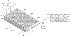
- n times n electro-magnetic actuators 140 of the electro-magnetic actuatorscan be equidistantly spaced and arranged in n rows 150 and in n columns 160 , wherein n can be six, e.g. as depicted in FIGS. 1 and 3 . In alternative embodiments, n may be four, five or greater than six.
- the laboratory sample distribution system 100can be operated by a method as follows.
- At least one transport plane module 130 a of the transport plane modulescan be assigned to a route category such as, for example, by the control device 170 .
- At least two traffic lanes 200 , 201can be formed on the route categorized transport plane module 130 a .
- the sample container carriers 110can be moved within each traffic lane 200 , 201 in a given transport direction.
- the transport directions of the at least two traffic lanescan be opposite to each other. A change from one transport direction and the one traffic lane 200 , respectively, to the opposite transport direction and the another traffic lane 201 , respectively, and vice versa cannot be possible for the sample container carriers 110 moved on the route categorized transport plane module 130 a.
- At least one another transport plane module 130 b of the transport plane modulescan be assigned to a waypoint category such as, for example, by the control device 170 .
- a change from one transport direction to the opposite transport direction and vice versacan be enabled for the sample container carriers 110 moved on the waypoint categorized transport plane module 130 b.
- FIG. 3schematically shows two transport plane modules 130 a assigned to the route category.
- a logical field with no hatchdenotes a field of a traffic lane.
- traffic lanes 200 with a given transport directioncan be formed, in FIG. 3 from left to right as depicted by arrows.
- traffic lanes 201 with a given opposite transport directioncan be formed, in FIG. 3 from right to left.
- the traffic lanes 200 , 201can be formed or arranged directly next to each other.
- a change from one transport direction to the opposite transport direction and vice versamay not be possible for the sample container carriers 110 moved on the route categorized transport plane modules 130 a .
- the transport plane modules 130 acan be arranged, such that the traffic lanes 200 , 201 on the modules can be in extension of each other.
- a logical field with a hatch from top right to bottom leftdenotes a field of a buffer lane.
- two buffer lanes 230can be formed on each route categorized transport plane module 130 a next to a traffic lane 200 , 201 of the traffic lanes, in one embodiment directly next to the in FIG. 3 outer traffic lanes 200 , 201 to the outside of them.
- Each of the buffer lanes 230can be configured to receive a number of the sample container carriers 110 from the corresponding traffic lane 200 , 201 , to buffer the received sample container carriers and to return the buffered sample container carriers to the corresponding traffic lane, as depicted in FIG. 3 by arrows.
- the transport plane modules 130 acan be arranged, such that the buffer lanes 230 on the modules can be in extension of each other.
- the traffic lanes 200 , 201 and the buffer lanes 230 formed on the route categorized transport plane modules 130 acan be symmetrically arranged such as, for example, rotationally-symmetrically around 180 degrees.
- FIG. 4schematically shows another embodiment with two other transport plane modules 130 a assigned to the route category.
- one traffic lane 200 with a given transport directioncan be formed on each transport plane module 130 a .
- one traffic lane 201 with a given opposite transport directioncan be formed on each transport plane module 130 a .
- the traffic lanes 200 , 201can be formed or arranged apart from each other.
- each route categorized transport plane module 130 a next to the traffic lanes 200201 such as, for example, directly next to them, four buffer lanes 230 can be formed.
- the one traffic lane 200can be arranged in between two of the four buffer lanes 230 .
- the another traffic lane 201can be arranged in between two other of the four buffer lanes 230 .
- FIG. 5schematically shows another embodiment with two transport plane modules 130 a assigned to the route category and one transport plane module 130 b assigned to the waypoint category.
- the waypoint categorized transport plane module 130 bcan be arranged in between the route categorized transport plane modules 130 a such as, for example, on a straight.
- the route categorized transport plane modules 130 acan be similar to the modules depicted in FIG. 3 .
- a change from one transport direction to the opposite transport direction and vice versacan be enabled for the sample container carriers 110 moved on the waypoint categorized transport plane module 130 b.
- a logical field with a hatch from top left to bottom rightdenotes a field of a change area.
- a change area 210can be formed on the waypoint categorized transport plane module 130 b .
- the change area 210can be formed in the center of the module 130 b .
- the change area 210can be configured to receive a sample container carrier 110 of the sample container carriers from the one traffic lane 200 with a given transport direction and to pass the received sample container carrier to the another traffic lane 201 with an opposite transport direction and vice versa.
- two such as, for example, adjacent, traffic lanes 200 with a given transport directioncan be formed, in FIG. 5 from left to right.
- two, in one embodiment adjacent, traffic lanes 201 with a given opposite transport directioncan be formed, in FIG. 5 from right to left.
- the change area 210can be arranged in between the opposite traffic lanes 200 , 201 at their sides such as, for example, directly next to the in FIG. 5 inner traffic lanes to the inside of them.
- the change area 210can be configured to receive a sample container carrier 110 of the sample container carriers from one of the traffic lanes 200 formed on the waypoint categorized transport plane module 130 b and to pass the received sample container carrier 110 to another of the traffic lanes 201 formed on the waypoint categorized transport plane module 130 b , in FIG. 5 from top to bottom, and vice versa, as depicted by arrows.
- the traffic lanes 200 , 201 formed on the waypoint categorized transport plane module 130 bcan be in extension of the traffic lanes 200 , 201 formed on the route categorized transport plane modules 130 a.
- the change area 210can be completely surrounded by the traffic lanes 200 , 201 formed on the waypoint categorized transport plane module 130 b.
- the traffic lanes 200 , 201 and change area 210 formed on the waypoint categorized transport plane module 130 bcan be symmetrically arranged such as, for example, rotationally-symmetrically around 180 degrees.
- a sample container carrier 110 of the sample container carriers coming from the in FIG. 5 left route categorized transport plane module 130 a onto the waypoint categorized transport plane module 130 bmay be received from the left from the one traffic lane 200 by the top left field of the change area 210 , passed to the bottom left field of the change area 210 and passed to the left to the another traffic lane 201 .
- a sample container carrier 110 coming from the in FIG. 5 right route categorized transport plane module 130 a onto the waypoint categorized transport plane module 130 bmay be received from the right from the another traffic lane 201 by the bottom right field of the change area 210 , passed to the top right field of the change area 210 and passed to the right to the one traffic lane 200 .
- transport paths of direction changing sample container carrierssuch as, for example, having opposite directions, may not cross or intersect each other.
- FIG. 6schematically shows another embodiment with two transport plane modules 130 a assigned to the route category and two transport plane modules 130 b assigned to the waypoint category.
- the waypoint categorized transport plane modules 130 bcan be arranged in between the route categorized transport plane modules 130 a such as, for example, on a straight.
- the route categorized transport plane modules 130 aare similar to the modules depicted in FIG. 4 .
- the waypoint categorized transport plane modules 130 bcan be similar to the route categorized transport plane modules 130 a with the exception that on each waypoint categorized transport plane module 130 b , the inner buffer lanes 230 are replaced by a change area 210 .
- each of the change areas 210can be arranged in between the opposite traffic lanes 200 , 201 at their sides such as, for example, directly next to them.
- the transport plane modules 130 a and the waypoint categorized transport plane modules 130 bcan be arranged, such that the traffic lanes 200 , 201 on the modules can be in extension of each other. Further, they can be arranged such, that the, and in one embodiment, outer, buffer lanes can be in extension of each other.
- the change area 210 on the in FIG. 6 left waypoint categorized transport plane module 130 bcan be configured to receive a sample container carrier 110 from the traffic lane 200 formed on the waypoint categorized transport plane module 130 b and to pass the received sample container carrier 110 to the another traffic lane 201 formed on the waypoint categorized transport plane module 130 b , in FIG. 6 from top to bottom.
- the sample container carriers 110can be moved within the change area 210 , and in one embodiment only, in a single direction, as depicted by arrows.
- a change within the change area 210can be possible only from the one traffic lane 200 with a given transport direction to the another traffic lane 201 with an opposite transport direction and not from the another traffic lane to the one traffic lane.
- the change area 210 on the in FIG. 6 right waypoint categorized transport plane module 130 bcan be configured to receive a sample container carrier 110 from the another traffic lane 201 formed on the waypoint categorized transport plane module 130 b and to pass the received sample container carrier 110 to the one traffic lane 200 formed on the waypoint categorized transport plane module 130 b , in FIG. 6 from bottom to top.
- the sample container carriers 110can be moved within the change area 210 , and in one embodiment only, in a single direction, as depicted by arrows.
- a change within the change area 210can be possible only from the another traffic lane 201 with an opposite transport direction to the one traffic lane 200 with a given transport direction and not from the one traffic lane to the another traffic lane.
- a sample container carrier 110 coming from the in FIG. 6 left route categorized transport plane module 130 a onto the left waypoint categorized transport plane module 130 bmay be received from the top from the one traffic lane 200 by the change area 210 and passed to the bottom to the another traffic lane 201 .
- a sample container carrier 110 coming from the in FIG. 6 right route categorized transport plane module 130 a onto the right waypoint categorized transport plane module 130 bmay be received from the bottom from the another traffic lane 201 by the change area 210 and passed to the top to the one traffic lane 200 .
- the change areasmay be arranged, such that transport paths of direction changing sample container carriers such as, for example, having opposite directions, may not cross or intersect each other.
- the traffic lanes 200 , 201 , the buffer lanes 230 and the change areas 210 formed on the waypoint categorized transport plane modules 130 bcan be symmetrically arranged such as, for example, rotationally-symmetrically around 180 degrees.
- FIG. 7schematically shows another embodiment with two transport plane modules 130 a assigned to the route category and one transport plane module 130 b assigned to the waypoint category.
- This embodimentis similar to the embodiment shown in FIG. 5 with the exception that the modules are not arranged on a straight.
- the waypoint categorized transport plane module 130 bcan be arranged in between the route categorized transport plane modules 130 a , in particular such that the modules form a curve, a turn or a corner.
- route categorized transport plane modules 130 aare similar to the route categorized transport plane modules depicted in FIGS. 3 and/or 5 .
- the waypoint categorized transport plane module 130 bis similar to the waypoint categorized transport plane module depicted in FIG. 5 with the exception that the traffic lanes 200 , 201 form a curve. Moreover, the change area 210 can be completely surrounded by the traffic lanes 200 , 201 formed on the waypoint categorized transport plane module 130 b , in one embodiment, such that this may allow to receive and/or to pass a sample container carrier 110 from and/or to all sides of the change area 210 , as depicted in FIG. 7 by arrows.
- FIG. 8schematically shows another embodiment with two transport plane modules 130 a assigned to the route category and one transport plane module 130 b assigned to the waypoint category.
- This embodimentis similar to the embodiment shown in FIG. 6 with the exception that here is, in particular only, one waypoint categorized transport plane module 130 b present and that the modules are not arranged on a straight.
- the waypoint categorized transport plane module 130 bcan be arranged in between the route categorized transport plane modules 130 a , in one embodiment, such that the modules form a curve.
- route categorized transport plane modules 130 aare similar to the route categorized transport plane modules depicted in FIGS. 4 and/or 6 .
- the waypoint categorized transport plane module 130 bcan be similar to the waypoint categorized transport plane modules depicted in FIG. 6 with the exception that the traffic lanes 200 , 201 form a curve and that the, in one embodiment two, change areas 210 can be formed on the, in one embodiment, one, waypoint categorized transport plane module 130 b.
- a buffer lane 230can be arranged in between the traffic lanes 200 , 201 on the waypoint categorized transport plane module 130 b.
- a logical field completely filled or in blackdenotes a field, which may not be needed.
- FIG. 9schematically shows another embodiment with four transport plane modules 130 a assigned to the route category and one transport plane module 130 b assigned to the waypoint category.
- the route categorized transport plane modules 130 aare similar to the route categorized transport plane modules depicted in FIGS. 3, 5 and/or 7 .
- the waypoint categorized transport plane module 130 bcan be arranged in between the route categorized transport plane modules 130 a , in one embodiment such that the modules form a cross.
- a different number as four route categorized transport plane modulesmay be present.
- three route categorized transport plane modulesmay be present, and in one embodiment, such that the modules form a T.
- two route categorized transport plane modulesmay be present, and in one embodiment, arranged on a straight or such that the modules form a curve.
- a change area 210can be formed in the center of the waypoint categorized transport plane module 130 b .
- the sample container carriers 110can be moved within the change area 210 , and in one embodiment, only, in a single direction, as depicted in FIG. 9 by arrows.
- the sample container carriers 110can be moved within the change area 210 in a circle such as, for example, clockwise. In alternative embodiments, the sample container carriers may be moved within the change area anticlockwise.
- traffic lanes 200can be formed.
- a logical field with a hatch from top left to bottom right and from top right to bottom leftdenotes a field of an enter area.
- an enter area 220can be formed, and in one embodiment, four enter areas 220 can be formed. Each of the enter areas 220 can be arranged in between the change area 210 and a traffic lane 200 , 201 of the traffic lanes directing to the change area 210 , and in one embodiment, in extension of the traffic lane 200 , 201 .
- Each of the enter areas 220can be configured to receive a sample container carrier 110 of the sample container carriers from the traffic lane 200 , 201 and to pass the received sample container carrier 110 to the change area 210 , when there is no cross traffic within the change area 210 blocking the sample container carrier 110 .
- the traffic lanes 200 , 201 , the change area 210 and the enter areas 220 formed on the waypoint categorized transport plane module 130 bcan be symmetrically arranged such as, for example, rotationally-symmetrically around 90 degrees.
- FIG. 10schematically shows another embodiment with four transport plane modules 130 a assigned to the route category and four transport plane modules 130 b assigned to the waypoint category.
- This embodimentis similar to the embodiment shown in FIG. 9 with the exception that here can be four waypoint categorized transport plane modules 130 b present.
- the waypoint categorized transport plane modules 130 bcan be arranged in between the route categorized transport plane modules 130 a such that the modules form a cross, for example.
- a route categorized transport plane module 130 acan be arranged to the left of the top left waypoint categorized transport plane module 130 b .
- a route categorized transport plane module 130 acan be arranged to the top of the top right waypoint categorized transport plane module 130 b .
- a route categorized transport plane module 130 acan be arranged to the right of the bottom right waypoint categorized transport plane module 130 b .
- a route categorized transport plane module 130 acan be arranged.
- the route categorized transport plane modules and/or the waypoint categorized transport plane modulesmay be arranged in a different manner.
- route categorized transport plane modules 130 acan be similar to the route categorized transport plane modules depicted in FIGS. 3, 5, 7 and/or 9 .
- the waypoint categorized transport plane modules 130 bcan be similar to the waypoint categorized transport plane module depicted in FIG. 6 with the exception that the change area 210 can be formed on the, and in one embodiment four, waypoint categorized transport plane modules 130 b.
- a buffer lane 230can be arranged on the waypoint categorized transport plane modules 130 b .
- the buffer lane 230can be completely surrounded by the change area 210 . In one embodiment, such that this may allow to receive a number of the sample container carriers 110 from the change area 210 to all sides of the buffer lane 230 and/or to return the buffered sample container carriers 110 to the change area 210 from all sides of the buffer lane 23 , as depicted in FIG. 10 by arrows.
- the traffic lanes 200 , 201 , the buffer lane 230 , the change area 210 and the enter areas 220 formed on the waypoint categorized transport plane modules 130 bcan be symmetrically arranged such as, for example, rotationally-symmetrically around 90 degrees.
- FIG. 11schematically shows another embodiment with eight transport plane modules 130 a assigned to the route category and four transport plane modules 130 b assigned to the waypoint category.
- the waypoint categorized transport plane modules 130 bcan be arranged in between the route categorized transport plane modules 130 a , and in one embodiment such that the modules form a cross.
- a different number as eight route categorized transport plane modulesmay be present.
- four route categorized transport plane modulesmay be present such as, for example, arranged as depicted in FIG. 10 .
- six route categorized transport plane modulesmay be present such as, for example, such that the modules form a T.
- four route categorized transport plane modulesmay be present, and in one embodiment, arranged on a straight or such that the modules form a curve.
- route categorized transport plane modules 130 acan be similar to the route categorized transport plane modules depicted in FIGS. 4, 6 and/or 8 .
- waypoint categorized transport plane modules 130 bcan be similar to the waypoint categorized transport plane modules depicted in FIG. 10 with the exception that here are eight enter areas 220 present and the traffic lanes 200 , 201 can be arranged in a different manner.
- the traffic lanes 200 , 201 , the buffer lane 230 , the change area 210 and the enter areas 220 formed on the waypoint categorized transport plane modules 130 bcan be symmetrically arranged such as, for example, rotationally-symmetrically around 90 degrees.
- laboratory sample distribution system 100can be operated by the method as follows.
- the methodcan comprise checking the number of electro-magnetic actuators 140 for errors and forming and/or reforming the traffic lanes 200 , 201 and/or the buffer lane/s 230 and/or the change area/s 210 and/or the enter area/s 220 , and in one embodiment only, above error-free electro-magnetic actuators.
- a logical field with an Ecan denote a field with an erroneous electro-magnetic actuator 140 below.
- FIG. 12 aschematically shows a route categorized transport plane module 130 a , which can be in one embodiment similar to the route categorized transport plane modules depicted in FIG. 3 .
- the corresponding electro-magnetic actuatorcan be erroneous.
- the traffic lanes 200 and the buffer lane 230 next to the traffic lanes 200can be reformed or rearranged, and in one embodiment, only above error-free electro-magnetic actuators, as depicted in FIG. 12 b .
- the reformed buffer lane 230can be arranged in between the opposite traffic lanes 200 , 201 .
- the reformed buffer lane 230can be interrupted.
- the field denoted with the Emay not be used, and in one embodiment, at least until the error is solved.
- FIG. 13 aschematically shows three route categorized transport plane modules 130 a , which can be similar to the route categorized transport plane modules depicted in FIGS. 3, 12 a and 12 b .
- two, fields of the traffic lanes 200 denoted with the Ethe corresponding electro-magnetic actuators can be erroneous.
- the fields denoted with the Ecan be arranged apart from each other.
- the traffic lanes 200 and the buffer lane 230 next to the traffic lanes 200can be reformed, as depicted in FIG. 13 b .
- the reformed buffer lane 230can be partially arranged in between the opposite traffic lanes 200 , 201 and partially arranged in between the traffic lanes 200 .
- the reformed buffer lane 230can be interrupted.
- FIG. 14 aschematically shows three route categorized transport plane modules 130 a , which can be in one embodiment similar to the route categorized transport plane modules depicted in FIGS. 3 and 12 a - 13 b .
- two, fields of the traffic lanes 200 denoted with the Ethe corresponding electro-magnetic actuators can be erroneous.
- the fields denoted with the Ecan be arranged directly next to each other.
- the traffic lanes 200 , 201 and the buffer lanes 230can be reformed, as depicted in FIG. 14 b .
- the reformed traffic lanes 200and in one embodiment completely, surround the fields denoted with the E.
- the buffer lanes 230can be interrupted.
- laboratory sample distribution system 100can be operated by the method as follows.
- the methodcan comprise assigning at least three transport plane modules 130 c of the transport plane modules to a laboratory station category, and in one embodiment by the control device 170 .
- Handling a sample container carrier 110 of the sample container carriers, handling a sample container 120 and/or handling a sample by a laboratory station 20can be enabled on each of the laboratory station categorized transport plane modules 130 c.
- the methodcan comprise assigning at least four transport plane modules 130 b to the waypoint category.
- one of the waypoint categorized transport plane modules 130 bcan be assigned or arranged, and in one embodiment, directly next to it.
- the methodcan comprise assigning at least three transport plane modules 130 a to the route category. In between each two of the waypoint categorized transport plane modules 130 b , at least one of the route categorized transport plane modules 130 a can be arranged, and in one embodiment, directly next to one or both of them.
- the methodcan comprise determining a route for a movement of the sample container carrier 110 from one laboratory station categorized transport plane module 130 c to another laboratory station categorized transport plane module 130 c by listing the waypoint categorized transport plane modules 130 b and their order in between them.
- the methodcan also comprise moving the sample container carrier 110 from one waypoint categorized transport plane module 130 b to the next one according to the determined list.
- the sample container carrier 110can be moved from one laboratory station categorized transport plane module 130 c denoted with Dev 1 to another laboratory station categorized transport plane module 130 c denoted with Dev 2 .
- a routecan be determined by listing the waypoint categorized transport plane modules 130 b and their order in between them, e.g. denoted with Wp 1 , Wp 2 , Wp 3 , Wp 4 , Wp 9 , Wp 12 , Wp 13 and Wp 14 .
- the sample container carrier 110can be moved from one waypoint categorized transport plane module 130 b to the next one according to the determined list.
- the target laboratory station 20 next to the laboratory station categorized transport plane module 130 c denoted with Dev 2can go offline when the sample container carrier 110 is moved in between the waypoint categorized transport plane modules 130 b denoted with Wp 4 and Wp 9 . Then the sample container carrier 110 can be moved to another target laboratory station 20 next to the laboratory station categorized transport plane module 130 c denoted with Dev 3 .
- another routecan be determined by listing the waypoint categorized transport plane modules 130 b and their order in between them, e.g. denoted with Wp 9 , Wp 4 , Wp 5 and Wp 6 . Then, the sample container carrier 110 can be moved from one waypoint categorized transport plane module 130 b to the next one according to the determined list.
- laboratory sample distribution system 100 and the laboratory automation system 10may be changed.
- transport plane modules 130 a , 130 b , 130 cmay be added to the laboratory sample distribution system 100 and/or removed from the laboratory sample distribution system 100 and/or rearranged within the laboratory sample distribution system 100 .
- laboratory stations 20may be added to the laboratory automation system 10 and/or removed from the laboratory automation system 10 and/or rearranged with the laboratory automation system 10 . Accordingly, a categorization of a transport plane module 130 a , 130 b , 130 c may be changed.
- a traffic lane 200 , 201 , a change area 210 , an enter area 220 and/or a buffer lane 230 formed on the transport plane module 130 a , 130 b , 130 cmay be changed.
- the curve or corner formed at the waypoint categorized transport plane module 130 b denoted with Wp 3may be changed into a T-form by adding a transport plane module next to it to the top in FIG. 15 , as already present at the waypoint categorized transport plane module 130 b denoted with Wp 9 .
- the T-form at the waypoint categorized transport plane module 130 b denoted with Wp 9may be changed into a cross-form by adding a transport plane module next to it to the right in FIG. 15 .
- the T-form at the waypoint categorized transport plane module 130 b denoted with Wp 12may be changed into a curve by removing the transport plane modules next to it to the left in FIG. 15 .
- the term “substantially”is utilized herein to represent the inherent degree of uncertainty that may be attributed to any quantitative comparison, value, measurement, or other representation.
- the term “substantially”is also utilized herein to represent the degree by which a quantitative representation may vary from a stated reference without resulting in a change in the basic function of the subject matter at issue.
Landscapes
- Physics & Mathematics (AREA)
- Health & Medical Sciences (AREA)
- Life Sciences & Earth Sciences (AREA)
- Chemical & Material Sciences (AREA)
- Analytical Chemistry (AREA)
- Biochemistry (AREA)
- General Health & Medical Sciences (AREA)
- General Physics & Mathematics (AREA)
- Immunology (AREA)
- Pathology (AREA)
- Engineering & Computer Science (AREA)
- Mechanical Engineering (AREA)
- Automatic Analysis And Handling Materials Therefor (AREA)
Abstract
Description
Claims (11)
Applications Claiming Priority (3)
| Application Number | Priority Date | Filing Date | Title |
|---|---|---|---|
| EP17174346 | 2017-06-02 | ||
| EP17174346.1AEP3410123B1 (en) | 2017-06-02 | 2017-06-02 | Method of operating a laboratory sample distribution system, laboratory sample distribution system and laboratory automation system |
| EP17174346.1 | 2017-06-02 |
Publications (2)
| Publication Number | Publication Date |
|---|---|
| US20180348244A1 US20180348244A1 (en) | 2018-12-06 |
| US10989725B2true US10989725B2 (en) | 2021-04-27 |
Family
ID=59009587
Family Applications (1)
| Application Number | Title | Priority Date | Filing Date |
|---|---|---|---|
| US15/988,637Active2038-12-19US10989725B2 (en) | 2017-06-02 | 2018-05-24 | Method of operating a laboratory sample distribution system, laboratory sample distribution system, and laboratory automation system |
Country Status (4)
| Country | Link |
|---|---|
| US (1) | US10989725B2 (en) |
| EP (1) | EP3410123B1 (en) |
| JP (1) | JP6636087B2 (en) |
| CN (1) | CN109001479A (en) |
Cited By (5)
| Publication number | Priority date | Publication date | Assignee | Title |
|---|---|---|---|---|
| US20220089377A1 (en)* | 2020-09-23 | 2022-03-24 | Roche Diagnostics Operations, Inc. | Method for detecting and reporting an operation error in an in-vitro diagnostic system, a transport device for a laboratory sample distribution system, and a laboratory sample distribution system |
| US20220144556A1 (en)* | 2019-03-08 | 2022-05-12 | Hitachi High-Tech Corporation | Conveying Device, Sample Analysis System and Sample Pretreatment Device Including the Conveying Device, And Method for Conveying Conveyance Object |
| US11754578B2 (en) | 2020-12-21 | 2023-09-12 | Roche Diagnostics Operations, Inc. | Modular transport plane and laboratory distribution system |
| US20240067467A1 (en)* | 2021-01-15 | 2024-02-29 | Hitachi High-Tech Corporation | Sample Conveyance System and Sample Conveyance Method |
| US20240210124A1 (en)* | 2022-12-27 | 2024-06-27 | Tecan Trading Ag | Temperature equalizing plate for a microplate reader and microplate reader with such a temperature equalizing plate |
Families Citing this family (35)
| Publication number | Priority date | Publication date | Assignee | Title |
|---|---|---|---|---|
| EP2589967A1 (en) | 2011-11-04 | 2013-05-08 | Roche Diagnostics GmbH | Laboratory sample distribution system and corresponding method of operation |
| EP2995958A1 (en) | 2014-09-15 | 2016-03-16 | Roche Diagniostics GmbH | Method of operating a laboratory sample distribution system, laboratory sample distribution system and laboratory automation system |
| EP3095739A1 (en) | 2015-05-22 | 2016-11-23 | Roche Diagniostics GmbH | Method of operating a laboratory sample distribution system, laboratory sample distribution system and laboratory automation system |
| EP3096146A1 (en) | 2015-05-22 | 2016-11-23 | Roche Diagniostics GmbH | Method of operating a laboratory sample distribution system, laboratory sample distribution system and laboratory automation system |
| EP3112874A1 (en) | 2015-07-02 | 2017-01-04 | Roche Diagnostics GmbH | Storage module, method of operating a laboratory automation system and laboratory automation system |
| EP3121603A1 (en) | 2015-07-22 | 2017-01-25 | Roche Diagnostics GmbH | Sample container carrier, laboratory sample distribution system and laboratory automation system |
| EP3211429A1 (en) | 2016-02-26 | 2017-08-30 | Roche Diagnostics GmbH | Transport device having a tiled driving surface |
| EP3211428A1 (en) | 2016-02-26 | 2017-08-30 | Roche Diagnostics GmbH | Transport device unit for a laboratory sample distribution system |
| EP3211430A1 (en) | 2016-02-26 | 2017-08-30 | Roche Diagnostics GmbH | Transport device with base plate modules |
| CN109196363A (en) | 2016-06-03 | 2019-01-11 | 豪夫迈·罗氏有限公司 | Laboratory sample distribution system and laboratory automation system |
| EP3255519B1 (en) | 2016-06-09 | 2019-02-20 | Roche Diagniostics GmbH | Laboratory sample distribution system and method of operating a laboratory sample distribution system |
| JP6752350B2 (en) | 2016-08-04 | 2020-09-09 | エフ.ホフマン−ラ ロシュ アーゲーF. Hoffmann−La Roche Aktiengesellschaft | Laboratory sample distribution system and laboratory automation system |
| EP3330717B1 (en) | 2016-12-01 | 2022-04-06 | Roche Diagnostics GmbH | Laboratory sample distribution system and laboratory automation system |
| EP3355065B1 (en) | 2017-01-31 | 2021-08-18 | Roche Diagnostics GmbH | Laboratory sample distribution system and laboratory automation system |
| EP3357842B1 (en) | 2017-02-03 | 2022-03-23 | Roche Diagnostics GmbH | Laboratory automation system |
| EP3410123B1 (en) | 2017-06-02 | 2023-09-20 | Roche Diagnostics GmbH | Method of operating a laboratory sample distribution system, laboratory sample distribution system and laboratory automation system |
| EP3428653B1 (en) | 2017-07-13 | 2021-09-15 | Roche Diagnostics GmbH | Method of operating a laboratory sample distribution system, laboratory sample distribution system and laboratory automation system |
| EP3457144B1 (en) | 2017-09-13 | 2021-10-20 | Roche Diagnostics GmbH | Sample container carrier, laboratory sample distribution system and laboratory automation system |
| EP3456415B1 (en) | 2017-09-13 | 2021-10-20 | Roche Diagnostics GmbH | Sample container carrier, laboratory sample distribution system and laboratory automation system |
| EP3537159B1 (en) | 2018-03-07 | 2022-08-31 | Roche Diagnostics GmbH | Method of operating a laboratory sample distribution system, laboratory sample distribution system and laboratory automation system |
| EP3540443B1 (en) | 2018-03-16 | 2023-08-30 | Roche Diagnostics GmbH | Laboratory system, laboratory sample distribution system and laboratory automation system |
| US10457497B1 (en)* | 2018-04-13 | 2019-10-29 | Laitram, L.L.C. | Electromagnetic conveyor system |
| JP7241881B2 (en)* | 2019-07-24 | 2023-03-17 | 株式会社日立ハイテク | Specimen transport system |
| EP4101794A4 (en)* | 2020-02-05 | 2024-03-27 | Hitachi High-Tech Corporation | SAMPLE TRANSPORT SYSTEM AND SAMPLE TRANSPORT METHOD |
| EP3925911B1 (en) | 2020-06-19 | 2023-05-24 | Roche Diagnostics GmbH | Laboratory sample distribution system and corresponding method of operation |
| EP3940388B1 (en) | 2020-07-15 | 2024-04-10 | Roche Diagnostics GmbH | Laboratory sample distribution system and method for operating the same |
| EP3957999A1 (en)* | 2020-08-19 | 2022-02-23 | Roche Diagnostics GmbH | Laboratory sample distribution system |
| EP4001923B1 (en) | 2020-11-23 | 2024-06-05 | Roche Diagnostics GmbH | Laboratory sample distribution system and laboratory automation system |
| US11747356B2 (en) | 2020-12-21 | 2023-09-05 | Roche Diagnostics Operations, Inc. | Support element for a modular transport plane, modular transport plane, and laboratory distribution system |
| EP4155737A1 (en)* | 2021-09-28 | 2023-03-29 | F. Hoffmann-La Roche AG | Distribution system and method for distributing carriers |
| EP4187253B1 (en) | 2021-11-24 | 2025-07-02 | F. Hoffmann-La Roche AG | Distribution system |
| JP2025521840A (en) | 2022-06-28 | 2025-07-10 | エフ ホフマン-ラ ロッシュ アクチェン ゲゼルシャフト | Distribution system and method for distributing multiple carriers - Patents.com |
| JP2025524550A (en) | 2022-06-28 | 2025-07-30 | エフ ホフマン-ラ ロッシュ アクチェン ゲゼルシャフト | Safe Spot Pattern |
| EP4307193A1 (en) | 2022-07-12 | 2024-01-17 | Roche Diagnostics GmbH | Method of operating a laboratory sample distribution system, laboratory sample distribution system, and laboratory automation system |
| EP4306966A1 (en) | 2022-07-12 | 2024-01-17 | Roche Diagnostics GmbH | Method of operating a laboratory sample distribution system, laboratory sample distribution system, and laboratory automation system |
Citations (262)
| Publication number | Priority date | Publication date | Assignee | Title |
|---|---|---|---|---|
| US3273727A (en) | 1966-09-20 | Load handling apparatus | ||
| US3653485A (en) | 1971-03-05 | 1972-04-04 | Transportation Technology | An air bearing conveyor |
| US3901656A (en) | 1972-08-24 | 1975-08-26 | American Monitor Corp | Apparatus and method for preparing and presenting serum chemistries for analyzation |
| US4150666A (en) | 1977-06-27 | 1979-04-24 | Sherwood Medical Industries Inc. | Tube holder for blood collection tubes of different sizes |
| SU685591A1 (en) | 1977-08-01 | 1979-09-15 | Украинский Государственный Институт По Проектированию Металлургических Заводов | Tube mail despatch carrier |
| JPS56147209A (en) | 1980-04-16 | 1981-11-16 | Hitachi Kiden Kogyo Ltd | Automatic steering method for unattended carrying vehicle |
| US4395164A (en) | 1977-05-20 | 1983-07-26 | Krupp Polysius Ag | Pneumatic tube installation for posting samples of material |
| US4544068A (en) | 1983-08-16 | 1985-10-01 | The United States Of America As Represented By The Administrator Of The National Aeronautics And Space Administration | Laboratory glassware rack for seismic safety |
| JPS60223481A (en) | 1984-04-18 | 1985-11-07 | Nippon Telegr & Teleph Corp <Ntt> | Magnetically levitating guide device |
| JPS6169604A (en) | 1984-09-10 | 1986-04-10 | Mitsubishi Chem Ind Ltd | Conveyance device |
| GB2165515A (en) | 1984-10-12 | 1986-04-16 | Mitsubishi Chem Ind | Conveyor |
| JPS6181323A (en) | 1984-09-27 | 1986-04-24 | Mitsubishi Chem Ind Ltd | Aligned object moving device |
| JPS6194925A (en) | 1984-10-12 | 1986-05-13 | Mitsubishi Chem Ind Ltd | Transport equipment |
| JPS61174031A (en) | 1985-01-29 | 1986-08-05 | Youichi Oohira | Conveying device aimed at divergence, using linear induction motor type x-y actuator |
| JPS61217434A (en) | 1985-03-20 | 1986-09-27 | Mitsubishi Chem Ind Ltd | Conveying device |
| JPS62100161A (en) | 1985-10-23 | 1987-05-09 | Shin Etsu Chem Co Ltd | Planar motor |
| JPS6331918A (en) | 1986-07-16 | 1988-02-10 | フエコ・エンジニア−ド・システムズ・インコ−ポレ−テツド | Rotatable and retractable vessel holder and conveyor thereof |
| JPS6348169A (en) | 1986-08-14 | 1988-02-29 | Fuji Elelctrochem Co Ltd | piezoelectric actuator |
| JPS6382433U (en) | 1986-11-15 | 1988-05-30 | ||
| US4771237A (en) | 1986-02-19 | 1988-09-13 | Panametrics | Method and apparatus for calibrating a displacement probe using a polynomial equation to generate a displacement look-up table |
| JPS63290101A (en) | 1987-05-22 | 1988-11-28 | Toshiba Corp | Linear motor type conveyor system |
| JPH01148966A (en) | 1987-12-04 | 1989-06-12 | Hitachi Kiden Kogyo Ltd | Sample transport device |
| JPH01266860A (en) | 1988-04-19 | 1989-10-24 | Yukitaka Furukawa | Test tube holding tool permitting cooling of the test tube |
| JPH0287903A (en) | 1988-09-21 | 1990-03-28 | Daifuku Co Ltd | Carrying facility utilizing linear motor |
| DE3909786A1 (en) | 1989-03-24 | 1990-09-27 | Schlafhorst & Co W | Apparatus for transporting cops and tubes between planes changing in the course of transport |
| JPH03112393A (en) | 1989-09-21 | 1991-05-13 | Kao Corp | Conveyance device |
| JPH0338704Y2 (en) | 1986-04-30 | 1991-08-15 | ||
| JPH03192013A (en) | 1989-12-21 | 1991-08-21 | Toshiba Corp | display device |
| JPH04127063A (en) | 1990-09-19 | 1992-04-28 | Hitachi Ltd | Apparatus for distributing specimen for clinical examination |
| US5120506A (en) | 1988-12-16 | 1992-06-09 | Fuji Photo Film Co., Ltd. | Chemical analyzer |
| JPH0569350A (en) | 1991-09-11 | 1993-03-23 | Toshiba Corp | Orbital robotic equipment maintenance equipment |
| JPH05142232A (en) | 1991-11-20 | 1993-06-08 | Hitachi Ltd | Specimen allocating system for clinical |
| JPH05180847A (en) | 1991-12-31 | 1993-07-23 | Hiranuma Sangyo Kk | Automatic cycler for analyzer |
| JPH0626808A (en) | 1992-07-09 | 1994-02-04 | Ebara Corp | Sensor target |
| US5295570A (en) | 1989-06-10 | 1994-03-22 | W. Schlafhorst Ag & Co. | Magnetic guiding assembly for yarn packages transported on a textile machine |
| US5309049A (en) | 1991-08-05 | 1994-05-03 | Mitsubishi Jukogyo Kabushiki Kaisha | Alternating current magnetic levitation transport system |
| JPH06148198A (en) | 1992-11-05 | 1994-05-27 | Hitachi Ltd | Contamination preventing device for analyzing equipment |
| JPH06156730A (en) | 1992-11-13 | 1994-06-03 | Ebara Corp | Conveying device |
| EP0601213A1 (en) | 1992-10-29 | 1994-06-15 | Hamilton Bonaduz AG | Transportdevice for goods |
| JPH06211306A (en) | 1993-01-19 | 1994-08-02 | Ebara Corp | Substrate storage device |
| JPH07228345A (en) | 1994-02-14 | 1995-08-29 | Ebara Corp | Tunnel conveyer |
| JPH07236838A (en) | 1994-02-28 | 1995-09-12 | Teruaki Ito | Method for centrifugal separation treatment of specimen and apparatus therefor |
| US5457368A (en) | 1993-03-09 | 1995-10-10 | University Of Utah Research Foundation | Mechanical/electrical displacement transducer |
| JPH07301637A (en) | 1994-04-29 | 1995-11-14 | Syst Sutatsuku:Kk | Testee conveyor device |
| US5523131A (en) | 1994-11-01 | 1996-06-04 | Innovative Premiums Inc. | Self-propelled table novelty device |
| US5530345A (en) | 1992-09-30 | 1996-06-25 | Sgs-Thomson Microelectronics S.R.L. | An integrated hall•effect apparatus for detecting the position of a magnetic element |
| WO1996036437A1 (en) | 1995-05-15 | 1996-11-21 | Smithkline Beecham Corporation | Vial holder |
| JPH0917848A (en) | 1995-06-30 | 1997-01-17 | Nikon Corp | Magnetically levitated stage |
| EP0775650A1 (en) | 1995-11-24 | 1997-05-28 | André Dr. von Froreich | Conveyor system, especially for material carriers to be used in medical laboratories |
| US5636548A (en) | 1994-05-16 | 1997-06-10 | Tesoro Alaska Petroleum Company | Analog hall-effect liquid level detector and method |
| US5641054A (en) | 1992-07-07 | 1997-06-24 | Ebara Corporation | Magnetic levitation conveyor apparatus |
| US5651941A (en) | 1992-06-29 | 1997-07-29 | Dade International Inc. | Sample tube carrier |
| US5720377A (en) | 1995-07-14 | 1998-02-24 | Chiron Diagnostics Corporation | Magnetic conveyor system |
| US5735387A (en) | 1995-07-14 | 1998-04-07 | Chiron Diagnostics Corporation | Specimen rack handling system |
| US5788929A (en) | 1996-03-12 | 1998-08-04 | Nesti; Edmund D. | Sample temperature protection rack |
| JPH1183865A (en) | 1997-09-11 | 1999-03-26 | Hitachi Ltd | Sample transport system |
| EP0916406A2 (en) | 1997-11-13 | 1999-05-19 | Bayer Corporation | Puck for a sample tube |
| JPH11264828A (en) | 1998-03-19 | 1999-09-28 | Hitachi Ltd | Sample transport system |
| JPH11304812A (en) | 1998-04-20 | 1999-11-05 | Hitachi Ltd | Sample processing system |
| JPH11326336A (en) | 1998-05-19 | 1999-11-26 | Aloka Co Ltd | Label reading apparatus |
| US6045319A (en) | 1997-08-11 | 2000-04-04 | Murata Kikai Kabushiki Kaisha | Carrier transport device |
| JP2000105243A (en) | 1998-09-29 | 2000-04-11 | Hitachi Ltd | Rack transport device |
| JP2000105246A (en) | 1998-09-29 | 2000-04-11 | Hitachi Ltd | Automatic analyzer |
| US6062398A (en) | 1999-07-21 | 2000-05-16 | Thalmayr; Hermann | Insert for holding test tubes in a conveyor capsule of a pneumatic tube conveyor system |
| US6141602A (en) | 1997-09-25 | 2000-10-31 | Hitachi, Ltd. | Specimen processing system |
| US6151535A (en) | 1998-05-04 | 2000-11-21 | Olympus Diagnostica Gmbh | Laboratory primary sample distributor with archiving mode |
| US6184596B1 (en) | 1995-06-30 | 2001-02-06 | Nikon Corporation | Stage construction incorporating magnetically levitated movable stage |
| US6191507B1 (en) | 1997-05-02 | 2001-02-20 | Ats Automation Tooling Systems Inc. | Modular conveyor system having multiple moving elements under independent control |
| US6206176B1 (en) | 1998-05-20 | 2001-03-27 | Applied Komatsu Technology, Inc. | Substrate transfer shuttle having a magnetic drive |
| JP2001124786A (en) | 1999-10-29 | 2001-05-11 | Hitachi Eng Co Ltd | Sample sorting device |
| US6255614B1 (en) | 1999-05-14 | 2001-07-03 | Sysmex Corporation | Specimen-container transfer apparatus |
| US6260360B1 (en) | 1997-11-24 | 2001-07-17 | Isosafe Limited | Container |
| EP1122194A1 (en) | 2000-02-01 | 2001-08-08 | Johnson & Johnson Vision Care, Inc. | Apparatus and method for automated warehousing |
| US6279728B1 (en) | 1998-07-20 | 2001-08-28 | Norbert G Jung | Electro-magnetic conveyor |
| JP2001240245A (en) | 2000-03-01 | 2001-09-04 | Auto Cs Engineering Co Ltd | Conveying system and conveying device by compressed air |
| US6293750B1 (en) | 1998-07-14 | 2001-09-25 | Bayer Corporation | Robotics for transporting containers and objects within an automated analytical instrument and service tool for servicing robotics |
| US20020009391A1 (en) | 1999-05-03 | 2002-01-24 | Ljl Biosystems, Inc. | Integrated sample-processing system |
| US6429016B1 (en) | 1999-10-01 | 2002-08-06 | Isis Pharmaceuticals, Inc. | System and method for sample positioning in a robotic system |
| US6444171B1 (en) | 1998-07-31 | 2002-09-03 | Hitachi, Ltd. | Sample processing system |
| US20030092185A1 (en) | 2001-03-16 | 2003-05-15 | Humayun Qureshi | Method and system for automated immunochemistry analysis |
| WO2003042048A2 (en) | 2001-11-14 | 2003-05-22 | Dade Behring Inc. | Bi-directional magnetic sample rack conveying system |
| US20040050836A1 (en) | 2000-09-29 | 2004-03-18 | Nesbitt Geoffrey John | Assembly of an integrated vessel transporter and at least one reaction vessel and integrated vessel transporter for transporting a chemical substance |
| US20040084531A1 (en) | 2002-11-01 | 2004-05-06 | Teruaki Itoh | Bar code generating apparatus |
| JP2005001055A (en) | 2003-06-11 | 2005-01-06 | Fanuc Ltd | Robot device |
| US20050061622A1 (en) | 2001-10-29 | 2005-03-24 | Martin Kevin Joseph | Conveying apparatus |
| EP1524525A1 (en) | 2003-10-14 | 2005-04-20 | Ortho-Clinical Diagnostics, Inc. | Moving evaporation control cover |
| US20050109580A1 (en) | 2003-11-26 | 2005-05-26 | Cynthia Thompson | Conveyor belt cleaning apparatus |
| US20050196320A1 (en) | 2004-03-05 | 2005-09-08 | Beckman Coulter, Inc. | Specimen-transport module for a multi-instrument clinical workcell |
| US20050194333A1 (en) | 2004-03-05 | 2005-09-08 | Beckman Coulter, Inc. | Specimen-container rack for automated clinical instrument |
| JP2005249740A (en) | 2004-03-08 | 2005-09-15 | Olympus Corp | Sample rack conveyer, and sample rack conveying method |
| US20050226770A1 (en) | 2002-09-26 | 2005-10-13 | Biopath Automation, L.L.C. | Apparatus and methods for automated handling and embedding of tissue samples |
| US20050242963A1 (en) | 2004-03-19 | 2005-11-03 | Applera Corporation | Sample carrier device incorporating radio frequency identification, and method |
| US20050247790A1 (en) | 2004-04-26 | 2005-11-10 | Ids Co., Ltd. | Reading apparatus for bar code on a test tube |
| US20050260101A1 (en) | 2000-10-10 | 2005-11-24 | Matthias Nauck | Closure element and closure system |
| US20050271555A1 (en) | 2004-04-07 | 2005-12-08 | Ids Co., Ltd. | Self-running sample holder and system having self-running sample holders |
| US20060000296A1 (en) | 2004-07-02 | 2006-01-05 | Salter Jason P | Synchronization of sample and data collection |
| US20060047303A1 (en) | 2004-07-28 | 2006-03-02 | Ethicon Endo-Surgery, Inc. | Electroactive polymer-based actuation mechanism for grasper |
| US7028831B2 (en) | 2004-03-05 | 2006-04-18 | Beckman Coulter, Inc. | Magnetic specimen-transport system for automated clinical instrument |
| JP2006106008A (en) | 2005-12-20 | 2006-04-20 | Jsk Kk | Capacitance type detector |
| US7078082B2 (en) | 2004-01-15 | 2006-07-18 | Sonoco Development, Inc. | Dual-functioning mechanism for startup during winding of web material and for splicing during unwinding |
| US20060219524A1 (en) | 2005-04-05 | 2006-10-05 | Kelly Carol L | Mountable cleaning apparatus for commercial conveyors |
| US7122158B2 (en) | 2002-02-28 | 2006-10-17 | Teruaki Itoh | Test tube holder |
| WO2007024540A1 (en) | 2005-08-25 | 2007-03-01 | Coldtrack, Llc | Hierarchical sample coding and storage system |
| US20070116611A1 (en) | 2005-11-14 | 2007-05-24 | Demarco Nicholas | Fraction collection system |
| US20070210090A1 (en) | 2004-01-08 | 2007-09-13 | Bernhard Sixt | Transport Container For Keeping Frozen Material Chilled |
| US20070248496A1 (en) | 2006-04-25 | 2007-10-25 | Ecocap's S.R.L. | Resealer of test tubes for clinical analyses fed from ready-to-use containers of sealing tape |
| JP2007309675A (en) | 2006-05-16 | 2007-11-29 | Olympus Corp | Sample rack supply-and-recovery system |
| US20070276558A1 (en) | 2004-03-27 | 2007-11-29 | Kyeong-Keun Kim | Navigation system for position self control robot and floor materials for providing absolute coordinates used thereof |
| JP2007314262A (en) | 2006-05-23 | 2007-12-06 | Daifuku Co Ltd | Article processing equipment |
| JP2007322289A (en) | 2006-06-01 | 2007-12-13 | Olympus Corp | Conveyer |
| US20080012511A1 (en) | 2004-07-15 | 2008-01-17 | Nikon Corporation | Planar Motor Device, Stage Device, Exposure Device and Device Manufacturing Method |
| US7326565B2 (en) | 2002-11-19 | 2008-02-05 | Sanyo Electric Co., Ltd. | Storage apparatus |
| US20080029368A1 (en) | 2004-12-20 | 2008-02-07 | Kyushu Institute Of Technology | Non-Contact Conveying Device Using Superconducting Magnetic Levitation |
| US20080056328A1 (en) | 2005-08-19 | 2008-03-06 | F.O.B. Instruments, Ltd. | Apparatus and Method for Determining the Amount of Time until a Desired Temperature is Reached |
| CN201045617Y (en) | 2006-04-21 | 2008-04-09 | 北京赛科希德科技发展有限公司 | Test cup continuous conveyer for full-automatic cruor measurement |
| US20080131961A1 (en) | 2003-06-04 | 2008-06-05 | Genial Genetic Solutions Limited | Biological Apparatus |
| US7425305B2 (en) | 2002-11-29 | 2008-09-16 | Teruaki Itoh | Specimen dispensing system |
| US7428957B2 (en) | 2003-08-26 | 2008-09-30 | Ssi Schaefer Peen Gmbh | Order picking station and order picking method |
| WO2008133708A1 (en) | 2007-05-01 | 2008-11-06 | Siemens Healthcare Diagnostics Inc. | Programmable random access sample handler for use within an automated laboratory system |
| WO2009002358A1 (en) | 2007-06-26 | 2008-12-31 | Siemens Healthcare Diagnostics Inc. | Mobile sample storage and retrieval unit for a laboratory automated sample handling worksystem |
| US20090004732A1 (en) | 2007-06-06 | 2009-01-01 | Labarre Paul Donald | Chemical Temperature Control |
| US20090022625A1 (en) | 2007-07-19 | 2009-01-22 | Samsung Electronics Co., Ltd. | Biochemical analyzer and method of controlling internal temperature of the biochemical analyzer |
| JP2009036643A (en) | 2007-08-01 | 2009-02-19 | Astec Corp:Kk | Control device for test tube input pattern to rack |
| US20090081771A1 (en) | 2003-06-06 | 2009-03-26 | Micronics, Inc. | System and method for heating, cooling and heat cycling on microfluidic device |
| JP2009062188A (en) | 2007-09-10 | 2009-03-26 | Tsubakimoto Chain Co | Sorting device using linear guide motor type x-y actuator |
| US20090128139A1 (en) | 2007-11-20 | 2009-05-21 | Drenth Joseph B | Magnet position locator |
| US20090142844A1 (en) | 2005-07-08 | 2009-06-04 | Horiba Abx Sas | Automatic Method of Preparing Samples of Total Blood For Analysis, and an Automatic Device For Implementing the Method |
| JP2009145188A (en) | 2007-12-13 | 2009-07-02 | Horiba Ltd | Test tube holder and sample suction apparatus |
| US20090180931A1 (en) | 2007-09-17 | 2009-07-16 | Sequenom, Inc. | Integrated robotic sample transfer device |
| US7578383B2 (en) | 2006-08-31 | 2009-08-25 | Ids Co., Ltd. | Specimen transport system |
| US7597187B2 (en) | 2007-03-26 | 2009-10-06 | Kba-Metronic Ag | Conveyor system |
| EP2119643A1 (en) | 2008-05-16 | 2009-11-18 | TGW Mechanics GmbH | Method and storage system for consolidating of shipping units |
| JP2009300402A (en) | 2008-06-17 | 2009-12-24 | Olympus Corp | Analyzer and analytical method |
| US20090322486A1 (en) | 2007-03-15 | 2009-12-31 | Joint Analytical Systems Gmbh | RFID Storage Systems |
| US20100000250A1 (en) | 2006-07-13 | 2010-01-07 | Bernhard Sixt | Transport container for maintaining the temperature of frozen goods |
| EP2148117A1 (en) | 2007-06-19 | 2010-01-27 | Kitz Corporation | Shaft sealing device, and valve structure using the device |
| WO2010042722A1 (en) | 2008-10-10 | 2010-04-15 | Quest Diagnostics Investments Incorporated | System and method for sorting specimen |
| US20100152895A1 (en) | 2008-12-05 | 2010-06-17 | Zhengshan Dai | Shock freezer and system for preparing samples for analysis using the same |
| US20100175943A1 (en) | 2007-06-02 | 2010-07-15 | Bergmann Lars B | Storage or Conveying System |
| US20100186618A1 (en) | 2009-01-23 | 2010-07-29 | Magnemotion, Inc. | Transport system powered by short block linear synchronous motors |
| WO2010087303A1 (en) | 2009-01-27 | 2010-08-05 | 株式会社日立ハイテクノロジーズ | Automated analyzer and automatic analysis method |
| US20100255529A1 (en) | 2007-12-07 | 2010-10-07 | Francesco Cocola | Device and method for microbiological analysis of biological samples |
| JP2010243310A (en) | 2009-04-06 | 2010-10-28 | Jeol Ltd | Automatic analyzer |
| WO2010129715A1 (en) | 2009-05-05 | 2010-11-11 | Cypress Semiconductor Corporation | Spill-over detection method and system |
| JP2010271204A (en) | 2009-05-22 | 2010-12-02 | Hitachi High-Technologies Corp | Sample transport system |
| US20100300831A1 (en) | 2007-11-30 | 2010-12-02 | Gianandrea Pedrazzini | System for automatically identifying, conveying and addressing biological material specimens |
| US20100312379A1 (en) | 2007-11-30 | 2010-12-09 | Gianandrea Pedrazzini | Automatic apparatus for loading and unloading biological material test tubes in a pneumatic mail system |
| US7858033B2 (en) | 2006-09-20 | 2010-12-28 | Ids Co., Ltd. | Specimen preprocessing/transport apparatus |
| US7875254B2 (en) | 2006-07-10 | 2011-01-25 | Exxonmobil Chemical Patents Inc. | Internal loop reactor and Oxo process using same |
| US20110050213A1 (en) | 2008-01-16 | 2011-03-03 | Kabushiki Kaisha Bridgestone | Belt monitoring system |
| US7939484B1 (en) | 2009-10-27 | 2011-05-10 | Clariant International, Ltd. | Method for reducing the adhesion forces between hard surfaces and subsequently occurring soil |
| US20110124038A1 (en) | 2009-05-15 | 2011-05-26 | Biomerieux, Inc. | Automated transfer mechanism for microbial detection apparatus |
| EP2327646A1 (en) | 2009-11-26 | 2011-06-01 | GLP systems GmbH | Switch in a branch of a transport path for laboratory samples in an analytical laboratory |
| CN102109530A (en) | 2009-12-28 | 2011-06-29 | 希森美康株式会社 | Sample processing apparatus and sample rack transport method |
| US20110172128A1 (en) | 2008-09-12 | 2011-07-14 | Anthony Davies | Multi-well device |
| US20110186406A1 (en) | 2010-01-29 | 2011-08-04 | Ecolab Usa Inc. | Clean conveyor sensing system |
| US20110287447A1 (en) | 2009-05-12 | 2011-11-24 | Life Technologies Corporation | Apparatus for and method of automated processing of biological samples |
| US20120037696A1 (en) | 2010-08-13 | 2012-02-16 | Lear Sirous Lavi | Transfer, Link, Bind, Specimen Tube Barcode Information To RFID Specimen Transport Puck In A Continuous Moving Binding Process Method |
| EP2447701A2 (en) | 2010-10-28 | 2012-05-02 | Sysmex Corporation | Sample processing system and method of processing sample |
| US20120129673A1 (en) | 2009-07-28 | 2012-05-24 | Hitachi High-Technologies Corporation | Centrifugal separator |
| US20120178170A1 (en) | 2009-07-16 | 2012-07-12 | Peter Van Praet | Sample container intelligent rack and loading method |
| DE102012000665A1 (en) | 2011-02-07 | 2012-08-09 | Sew-Eurodrive Gmbh & Co. Kg | sorter |
| US8240460B1 (en) | 2010-02-18 | 2012-08-14 | Michael James Bleau | Apparatus for cleaning a conveyor belt |
| US20120211645A1 (en) | 2011-02-23 | 2012-08-23 | JLT & Associates, Inc. | Conveyor sterilization |
| EP2500871A1 (en) | 2011-03-18 | 2012-09-19 | The Raymond Corporation | Integration of an autonomous industrial vehicle into an asset management system |
| US20120275885A1 (en) | 2011-04-29 | 2012-11-01 | Frederic Furrer | Method for operating an automated sample workcell |
| US20120282683A1 (en) | 2010-01-21 | 2012-11-08 | Kazunori Mototsu | Sample analysis device |
| US20120295358A1 (en) | 2010-01-21 | 2012-11-22 | Siemens Healthcare Diagnostics Inc. | Magnetic Conveyor Systems, Apparatus and Methods Including Moveable Magnet |
| WO2012158520A1 (en) | 2011-05-13 | 2012-11-22 | Beckman Coulter, Inc. | Laboratory product transport element and path arrangement |
| WO2012158541A1 (en) | 2011-05-13 | 2012-11-22 | Beckman Coulter, Inc. | System and method including laboratory product transport element |
| US20120310401A1 (en) | 2011-06-03 | 2012-12-06 | Rushabh Instruments, Inc. | Rotary tissue processor with configurable stations |
| WO2012170636A1 (en) | 2011-06-07 | 2012-12-13 | Magnemotion, Inc. | Versatile control of a linear synchronous motor propulsion system |
| US20130153677A1 (en) | 2010-09-07 | 2013-06-20 | University Of Limerick | Liquid droplet dispenser |
| DE102011090044A1 (en) | 2011-12-28 | 2013-07-04 | Siemens Healthcare Diagnostics Products Gmbh | Transport system and method of operation |
| US20130180824A1 (en) | 2009-03-03 | 2013-07-18 | Ats Automation Tooling Systems Inc. | Multi-mode and multi-pitch conveyor system |
| US8502422B2 (en) | 2007-04-16 | 2013-08-06 | Crisplant A/S | Sorting system with linear synchronous motor drive |
| JP2013172009A (en) | 2012-02-21 | 2013-09-02 | Hitachi Ltd | Flow soldering device and solder liquid surface adjustment method |
| JP2013190400A (en) | 2012-03-15 | 2013-09-26 | Hitachi High-Technologies Corp | Autoanalyzer |
| US20130263622A1 (en) | 2012-03-12 | 2013-10-10 | The World Egg Bank | Cryogenic sample holder |
| WO2013152089A1 (en) | 2012-04-04 | 2013-10-10 | Siemens Healthcare Diagnostics Inc. | Method for processing priority samples that preserves a fifo processing queue |
| WO2013169778A1 (en) | 2012-05-11 | 2013-11-14 | Siemens Healthcare Diagnostics Inc. | Method and system for transporting sample tubes |
| WO2013177163A1 (en) | 2012-05-24 | 2013-11-28 | Siemens Healthcare Diagnostics Inc. | Non-contact optical encoding scheme for intelligent automation puck |
| WO2013177087A2 (en) | 2012-05-22 | 2013-11-28 | Siemens Healthcare Diagnostics Inc. | Linear random access queue |
| US20130322992A1 (en) | 2011-02-16 | 2013-12-05 | Gianandrea Pedrazzini | Interfacing apparatus between a pneumatic mail system and a feeding system of biological product containers to a laboratory automation system |
| EP2502675B1 (en) | 2011-03-25 | 2014-02-12 | Symbion Medical Systems Sàrl | Container holder and container carrier |
| WO2014059134A1 (en) | 2012-10-11 | 2014-04-17 | Siemens Healthcare Diagnostics Inc. | Automation maintenance carrier |
| WO2014071214A1 (en) | 2012-11-01 | 2014-05-08 | Siemens Healthcare Diagnostics Inc. | Multiple carrier and sleeve tray |
| US20140170023A1 (en) | 2011-09-05 | 2014-06-19 | Hitachi High-Technologies Corporation | Automatic analyzer |
| US8796186B2 (en) | 2005-04-06 | 2014-08-05 | Affymetrix, Inc. | System and method for processing large number of biological microarrays |
| US20140231217A1 (en)* | 2011-11-04 | 2014-08-21 | Roche Diagnostics Operations, Inc. | Laboratory sample distribution system and corresponding method of operation |
| US20140234949A1 (en) | 2011-09-25 | 2014-08-21 | Theranos, Inc. | Systems and methods for fluid and component handling |
| US8833544B2 (en) | 2011-11-19 | 2014-09-16 | Robert Bosch Gmbh | Conveying device |
| US20150014125A1 (en) | 2012-02-15 | 2015-01-15 | Glp Systems Gmbh | Conveyor system for material samples, especially medical samples |
| US8973736B2 (en) | 2011-11-07 | 2015-03-10 | Beckman Coulter, Inc. | Magnetic damping for specimen transport system |
| US9056720B2 (en) | 2012-01-24 | 2015-06-16 | Robert Bosch Gmbh | Conveying device with articulated conveying element |
| EP2887071A1 (en) | 2013-12-19 | 2015-06-24 | F. Hoffmann-La Roche AG | Storage and supply of vessel holders |
| WO2015104263A2 (en) | 2014-01-08 | 2015-07-16 | Jakob Hatteland Logistics As | Robot for transporting storage bins |
| US9097691B2 (en) | 2007-05-16 | 2015-08-04 | Hitachi High-Technologies Corporation | Sample handling system |
| US20150241457A1 (en) | 2012-08-20 | 2015-08-27 | Siemens Healthcare Diagnostics Inc. | Methods and apparatus for ascertaining specimen and/or sample container characteristics while in transit |
| US20150276775A1 (en) | 2012-10-11 | 2015-10-01 | Siemens Healthcare Diagnostics Inc. | Modular workcells for lab automation |
| US20150273468A1 (en) | 2014-03-28 | 2015-10-01 | Brooks Automation, Inc. | Sample storage and retrieval system |
| US20150276782A1 (en) | 2014-03-31 | 2015-10-01 | Roche Diagnostics Operations, Inc. | Sample distribution system and laboratory automation system |
| US9211543B2 (en) | 2011-12-28 | 2015-12-15 | Hitachi High-Technologies Corporation | Holder for transferring test tube |
| US20160003859A1 (en) | 2013-11-07 | 2016-01-07 | Tecan Trading Ag | Microplate reader with incubation device |
| US9239335B2 (en) | 2011-11-04 | 2016-01-19 | Roche Diagnostics Operations, Inc. | Laboratory sample distribution system, laboratory system and method of operating |
| US20160025756A1 (en) | 2013-03-08 | 2016-01-28 | Siemens Healthcare Diagnostics Inc. | Tube characterization station |
| US20160054341A1 (en) | 2014-08-21 | 2016-02-25 | Roche Diagnostics Operations, Inc. | Sample container carrier for a laboratory sample distribution system, laboratory sample distribution system and laboratory automation system |
| US20160229565A1 (en) | 2015-02-11 | 2016-08-11 | Roche Diagnostics Operations, Inc. | Method and device for handling test tubes in a laboratory automation system |
| US9423411B2 (en) | 2014-02-17 | 2016-08-23 | Roche Diagnostics Operations, Inc. | Transport device, sample distribution system and laboratory automation system |
| US9423410B2 (en) | 2014-02-17 | 2016-08-23 | Roche Diagnostics Operations, Inc. | Transport device, sample distribution system, and laboratory automation system |
| US20160274137A1 (en) | 2015-03-16 | 2016-09-22 | Roche Diagnostics Operations, Inc. | Transport carrier, laboratory cargo distribution system, and laboratory automation system |
| US20160282378A1 (en) | 2015-03-23 | 2016-09-29 | Roche Diagnostics Operations, Inc. | Laboratory sample distribution system and laboratory automation system |
| US20160341750A1 (en) | 2015-05-22 | 2016-11-24 | Roche Diagnostics Operations, Inc. | Method of operating a laboratory automation system and a laboratory automation system |
| US20160341751A1 (en) | 2015-05-22 | 2016-11-24 | Roche Diagnostics Operations, Inc. | Method of operating a laboratory sample distribution system, laboratory sample distribution system and a laboratory automation system |
| US9567167B2 (en) | 2014-06-17 | 2017-02-14 | Roche Diagnostics Operations, Inc. | Laboratory sample distribution system and laboratory automation system |
| US20170059599A1 (en) | 2015-09-01 | 2017-03-02 | Roche Diagnostics Operations., Inc. | Laboratory cargo distribution system, laboratory automation system and method of operating a laboratory cargo distribution system |
| US9593970B2 (en) | 2014-09-09 | 2017-03-14 | Roche Diagnostics Operations, Inc. | Laboratory sample distribution system and method for calibrating magnetic sensors |
| US9618525B2 (en) | 2014-10-07 | 2017-04-11 | Roche Diagnostics Operations, Inc. | Module for a laboratory sample distribution system, laboratory sample distribution system and laboratory automation system |
| US20170101277A1 (en) | 2015-10-13 | 2017-04-13 | Roche Diagnostics Operations, Inc. | Laboratory sample distribution system and laboratory automation system |
| US20170108522A1 (en) | 2015-10-14 | 2017-04-20 | Roche Diagnostics Operations, Inc. | Method of rotating a sample container carrier, laboratory sample distribution system and laboratory automation system |
| US20170131307A1 (en) | 2014-07-23 | 2017-05-11 | Roche Diagnostics Operations, Inc. | Laboratory sample distribution system and laboratory automation system |
| US20170131310A1 (en) | 2014-07-23 | 2017-05-11 | Roche Diagnostics Operations, Inc. | Sample container carrier, laboratory sample distribution system and laboratory automation system |
| US20170138971A1 (en) | 2011-11-04 | 2017-05-18 | Roche Diagnostics Operations, Inc. | Laboratory sample distribution system and corresponding method of operation |
| US9658241B2 (en) | 2014-03-31 | 2017-05-23 | Roche Diagnostics Operations, Inc. | Sample distribution system and laboratory automation system |
| US20170168079A1 (en) | 2014-09-09 | 2017-06-15 | Roche Diagnostics Operations, Inc. | Set of sample container carriers for a laboratory sample distribution system, laboratory sample distribution system and laboratory automation system |
| US20170174448A1 (en) | 2014-09-09 | 2017-06-22 | Roche Diagnostics Operations, Inc. | Laboratory sample distribution system and laboratory automation system |
| US20170184622A1 (en) | 2014-09-15 | 2017-06-29 | Roche Diagnostics Operations, Inc. | Method of operating a laboratory sample distribution system, laboratory sample distribution system and laboratory automation system |
| US20170248624A1 (en) | 2016-02-25 | 2017-08-31 | Roche Diagnostics Operations, Inc. | Sample container carrier |
| US20170248623A1 (en) | 2016-02-25 | 2017-08-31 | Roche Diagnostics Operations, Inc. | Sample container carrier |
| US9772342B2 (en) | 2014-03-31 | 2017-09-26 | Roche Diagnostics Operations, Inc. | Dispatching device, sample distribution system and laboratory automation system |
| US9791468B2 (en) | 2014-03-31 | 2017-10-17 | Roche Diagnostics Operations, Inc. | Transport device, sample distribution system and laboratory automation system |
| US9810706B2 (en) | 2014-03-31 | 2017-11-07 | Roche Diagnostics Operations, Inc. | Vertical conveying device, laboratory sample distribution system and laboratory automation system |
| US20170363608A1 (en) | 2016-06-21 | 2017-12-21 | Roche Diagnostics Operations, Inc. | Method of setting a handover position and laboratory automation system |
| US9902572B2 (en) | 2015-10-06 | 2018-02-27 | Roche Diagnostics Operations, Inc. | Method of configuring a laboratory automation system, laboratory sample distribution system and laboratory automation system |
| US20180067141A1 (en)* | 2015-05-22 | 2018-03-08 | Roche Diagnostics Operations, Inc. | Method of operating a laboratory sample distribution system, laboratory sample distribution system and laboratory automation system |
| US9939455B2 (en) | 2014-11-03 | 2018-04-10 | Roche Diagnostics Operations, Inc. | Laboratory sample distribution system and laboratory automation system |
| US20180106821A1 (en) | 2015-07-02 | 2018-04-19 | Roche Diagnostics Operations, Inc. | Storage module, method of operating a laboratory automation system and laboratory automation system |
| US9952242B2 (en) | 2014-09-12 | 2018-04-24 | Roche Diagnostics Operations, Inc. | Laboratory sample distribution system and laboratory automation system |
| US20180128848A1 (en) | 2015-07-22 | 2018-05-10 | Roche Diagnostics Operations, Inc. | Sample container carrier, laboratory sample distribution system and laboratory automation system |
| US9969570B2 (en) | 2010-05-07 | 2018-05-15 | Roche Diagnostics Operations, Inc. | System for transporting containers between different stations and a container carrier |
| US9989547B2 (en) | 2014-07-24 | 2018-06-05 | Roche Diagnostics Operations, Inc. | Laboratory sample distribution system and laboratory automation system |
| US20180156835A1 (en) | 2016-12-01 | 2018-06-07 | Roche Diagnostics Operations, Inc. | Laboratory sample distribution system and laboratory automation system |
| US20180188280A1 (en) | 2016-12-29 | 2018-07-05 | Roche Diagnostics Operations, Inc. | Laboratory sample distribution system and laboratory automation system |
| US20180210000A1 (en) | 2017-01-24 | 2018-07-26 | Roche Diagnostics Operations, Inc. | Laboratory |
| US20180210001A1 (en) | 2017-01-25 | 2018-07-26 | Roche Diagnostics Operations, Inc. | Laboratory sample distribution system and laboratory automation system |
| US20180217174A1 (en) | 2017-01-31 | 2018-08-02 | Roche Diagnostics Operations, Inc. | Laboratory sample distribution system and laboratory automation system |
| US20180224476A1 (en) | 2017-02-03 | 2018-08-09 | Roche Diagnostics Operations, Inc. | Laboratory automation system |
| US20180340951A1 (en) | 2016-02-26 | 2018-11-29 | Roche Diagnostics Operations, Inc. | Transport device having a tilted driving surface |
| US20180340952A1 (en) | 2016-02-26 | 2018-11-29 | Roche Diagnostics Operations, Inc. | Transport device with base plate modules |
| US20180348244A1 (en) | 2017-06-02 | 2018-12-06 | Roche Diagnostics Operations, Inc. | Method of operating a laboratory sample distribution system, laboratory sample distribution system, and laboratory automation system |
| US20180348245A1 (en) | 2016-02-26 | 2018-12-06 | Roche Diagnostics Operations, Inc. | Transport device unit for a laboratory sample distribution system |
| US20190018027A1 (en) | 2017-07-13 | 2019-01-17 | Roche Diagnostics Operations, Inc. | Method of operating a laboratory sample distribution system, laboratory sample distribution system and laboratory automation system |
| US10197586B2 (en) | 2015-10-06 | 2019-02-05 | Roche Diagnostics Operations, Inc. | Method of determining a handover position and laboratory automation system |
| US20190076845A1 (en) | 2017-09-13 | 2019-03-14 | Roche Diagnostics Operations, Inc. | Sample container carrier, laboratory sample distribution system and laboratory automation system |
| US20190076846A1 (en) | 2017-09-13 | 2019-03-14 | Roche Diagnostics Operations, Inc. | Sample container carrier, laboratory sample distribution system and laboratory automation system |
| US20190086433A1 (en) | 2016-06-03 | 2019-03-21 | Roche Diagnostics Operations, Inc. | Laboratory sample distribution system and laboratory automation system |
| US20190094251A1 (en) | 2017-09-25 | 2019-03-28 | Roche Diagnostics Operations, Inc. | Method of handling a laboratory sample container, laboratory apparatus and laboratory automation system |
| US20190094252A1 (en) | 2016-06-09 | 2019-03-28 | Roche Diagnostics Operations, Inc. | Laboratory sample distribution system and method of operating a laboratory sample distribution system |
| US20190101468A1 (en) | 2017-10-04 | 2019-04-04 | Roche Diagnostics Operations, Inc. | Detector for a laboratory liquid distribution system, detector system for a laboratory liquid distribution system, laboratory liquid distribution system, laboratory automation system and use of a detector |
| US10288634B2 (en) | 2016-02-26 | 2019-05-14 | Roche Diagnostics Operations, Inc. | Device for mounting a plurality of actuator modules |
| US20190285660A1 (en) | 2018-03-16 | 2019-09-19 | Roche Diagnostics Operations, Inc. | Laboratory system, laboratory sample distribution system and laboratory automation system |
| US20200200783A1 (en) | 2018-12-21 | 2020-06-25 | Roche Diagnostics Operations, Inc. | Sample container carrier, laboratory sample distribution system and laboratory automation system |
- 2017
- 2017-06-02EPEP17174346.1Apatent/EP3410123B1/enactiveActive
- 2018
- 2018-05-24USUS15/988,637patent/US10989725B2/enactiveActive
- 2018-05-25JPJP2018100392Apatent/JP6636087B2/enactiveActive
- 2018-06-01CNCN201810555422.3Apatent/CN109001479A/enactivePending
Patent Citations (277)
| Publication number | Priority date | Publication date | Assignee | Title |
|---|---|---|---|---|
| US3273727A (en) | 1966-09-20 | Load handling apparatus | ||
| US3653485A (en) | 1971-03-05 | 1972-04-04 | Transportation Technology | An air bearing conveyor |
| US3901656A (en) | 1972-08-24 | 1975-08-26 | American Monitor Corp | Apparatus and method for preparing and presenting serum chemistries for analyzation |
| US4395164A (en) | 1977-05-20 | 1983-07-26 | Krupp Polysius Ag | Pneumatic tube installation for posting samples of material |
| US4150666A (en) | 1977-06-27 | 1979-04-24 | Sherwood Medical Industries Inc. | Tube holder for blood collection tubes of different sizes |
| SU685591A1 (en) | 1977-08-01 | 1979-09-15 | Украинский Государственный Институт По Проектированию Металлургических Заводов | Tube mail despatch carrier |
| JPS56147209A (en) | 1980-04-16 | 1981-11-16 | Hitachi Kiden Kogyo Ltd | Automatic steering method for unattended carrying vehicle |
| US4544068A (en) | 1983-08-16 | 1985-10-01 | The United States Of America As Represented By The Administrator Of The National Aeronautics And Space Administration | Laboratory glassware rack for seismic safety |
| JPS60223481A (en) | 1984-04-18 | 1985-11-07 | Nippon Telegr & Teleph Corp <Ntt> | Magnetically levitating guide device |
| JPS6169604A (en) | 1984-09-10 | 1986-04-10 | Mitsubishi Chem Ind Ltd | Conveyance device |
| JPS6181323A (en) | 1984-09-27 | 1986-04-24 | Mitsubishi Chem Ind Ltd | Aligned object moving device |
| GB2165515A (en) | 1984-10-12 | 1986-04-16 | Mitsubishi Chem Ind | Conveyor |
| JPS6194925A (en) | 1984-10-12 | 1986-05-13 | Mitsubishi Chem Ind Ltd | Transport equipment |
| JPS61174031A (en) | 1985-01-29 | 1986-08-05 | Youichi Oohira | Conveying device aimed at divergence, using linear induction motor type x-y actuator |
| JPS61217434A (en) | 1985-03-20 | 1986-09-27 | Mitsubishi Chem Ind Ltd | Conveying device |
| JPS62100161A (en) | 1985-10-23 | 1987-05-09 | Shin Etsu Chem Co Ltd | Planar motor |
| US4771237A (en) | 1986-02-19 | 1988-09-13 | Panametrics | Method and apparatus for calibrating a displacement probe using a polynomial equation to generate a displacement look-up table |
| JPH0338704Y2 (en) | 1986-04-30 | 1991-08-15 | ||
| JPS6331918A (en) | 1986-07-16 | 1988-02-10 | フエコ・エンジニア−ド・システムズ・インコ−ポレ−テツド | Rotatable and retractable vessel holder and conveyor thereof |
| JPS6348169A (en) | 1986-08-14 | 1988-02-29 | Fuji Elelctrochem Co Ltd | piezoelectric actuator |
| JPS6382433U (en) | 1986-11-15 | 1988-05-30 | ||
| JPS63290101A (en) | 1987-05-22 | 1988-11-28 | Toshiba Corp | Linear motor type conveyor system |
| JPH01148966A (en) | 1987-12-04 | 1989-06-12 | Hitachi Kiden Kogyo Ltd | Sample transport device |
| JPH01266860A (en) | 1988-04-19 | 1989-10-24 | Yukitaka Furukawa | Test tube holding tool permitting cooling of the test tube |
| JPH0287903A (en) | 1988-09-21 | 1990-03-28 | Daifuku Co Ltd | Carrying facility utilizing linear motor |
| US5120506A (en) | 1988-12-16 | 1992-06-09 | Fuji Photo Film Co., Ltd. | Chemical analyzer |
| DE3909786A1 (en) | 1989-03-24 | 1990-09-27 | Schlafhorst & Co W | Apparatus for transporting cops and tubes between planes changing in the course of transport |
| US5295570A (en) | 1989-06-10 | 1994-03-22 | W. Schlafhorst Ag & Co. | Magnetic guiding assembly for yarn packages transported on a textile machine |
| JPH03112393A (en) | 1989-09-21 | 1991-05-13 | Kao Corp | Conveyance device |
| JPH03192013A (en) | 1989-12-21 | 1991-08-21 | Toshiba Corp | display device |
| JPH04127063A (en) | 1990-09-19 | 1992-04-28 | Hitachi Ltd | Apparatus for distributing specimen for clinical examination |
| US5309049A (en) | 1991-08-05 | 1994-05-03 | Mitsubishi Jukogyo Kabushiki Kaisha | Alternating current magnetic levitation transport system |
| JPH0569350A (en) | 1991-09-11 | 1993-03-23 | Toshiba Corp | Orbital robotic equipment maintenance equipment |
| JPH05142232A (en) | 1991-11-20 | 1993-06-08 | Hitachi Ltd | Specimen allocating system for clinical |
| JPH05180847A (en) | 1991-12-31 | 1993-07-23 | Hiranuma Sangyo Kk | Automatic cycler for analyzer |
| US5651941A (en) | 1992-06-29 | 1997-07-29 | Dade International Inc. | Sample tube carrier |
| US5641054A (en) | 1992-07-07 | 1997-06-24 | Ebara Corporation | Magnetic levitation conveyor apparatus |
| JPH0626808A (en) | 1992-07-09 | 1994-02-04 | Ebara Corp | Sensor target |
| US5530345A (en) | 1992-09-30 | 1996-06-25 | Sgs-Thomson Microelectronics S.R.L. | An integrated hall•effect apparatus for detecting the position of a magnetic element |
| EP0601213A1 (en) | 1992-10-29 | 1994-06-15 | Hamilton Bonaduz AG | Transportdevice for goods |
| JPH06148198A (en) | 1992-11-05 | 1994-05-27 | Hitachi Ltd | Contamination preventing device for analyzing equipment |
| JPH06156730A (en) | 1992-11-13 | 1994-06-03 | Ebara Corp | Conveying device |
| JPH06211306A (en) | 1993-01-19 | 1994-08-02 | Ebara Corp | Substrate storage device |
| US5457368A (en) | 1993-03-09 | 1995-10-10 | University Of Utah Research Foundation | Mechanical/electrical displacement transducer |
| JPH07228345A (en) | 1994-02-14 | 1995-08-29 | Ebara Corp | Tunnel conveyer |
| JPH07236838A (en) | 1994-02-28 | 1995-09-12 | Teruaki Ito | Method for centrifugal separation treatment of specimen and apparatus therefor |
| JPH07301637A (en) | 1994-04-29 | 1995-11-14 | Syst Sutatsuku:Kk | Testee conveyor device |
| US5636548A (en) | 1994-05-16 | 1997-06-10 | Tesoro Alaska Petroleum Company | Analog hall-effect liquid level detector and method |
| US5523131A (en) | 1994-11-01 | 1996-06-04 | Innovative Premiums Inc. | Self-propelled table novelty device |
| WO1996036437A1 (en) | 1995-05-15 | 1996-11-21 | Smithkline Beecham Corporation | Vial holder |
| JPH0917848A (en) | 1995-06-30 | 1997-01-17 | Nikon Corp | Magnetically levitated stage |
| US6184596B1 (en) | 1995-06-30 | 2001-02-06 | Nikon Corporation | Stage construction incorporating magnetically levitated movable stage |
| US5720377A (en) | 1995-07-14 | 1998-02-24 | Chiron Diagnostics Corporation | Magnetic conveyor system |
| US5735387A (en) | 1995-07-14 | 1998-04-07 | Chiron Diagnostics Corporation | Specimen rack handling system |
| EP0775650A1 (en) | 1995-11-24 | 1997-05-28 | André Dr. von Froreich | Conveyor system, especially for material carriers to be used in medical laboratories |
| US5788929A (en) | 1996-03-12 | 1998-08-04 | Nesti; Edmund D. | Sample temperature protection rack |
| US6191507B1 (en) | 1997-05-02 | 2001-02-20 | Ats Automation Tooling Systems Inc. | Modular conveyor system having multiple moving elements under independent control |
| US6045319A (en) | 1997-08-11 | 2000-04-04 | Murata Kikai Kabushiki Kaisha | Carrier transport device |
| JPH1183865A (en) | 1997-09-11 | 1999-03-26 | Hitachi Ltd | Sample transport system |
| US6141602A (en) | 1997-09-25 | 2000-10-31 | Hitachi, Ltd. | Specimen processing system |
| EP0916406A2 (en) | 1997-11-13 | 1999-05-19 | Bayer Corporation | Puck for a sample tube |
| US6260360B1 (en) | 1997-11-24 | 2001-07-17 | Isosafe Limited | Container |
| JPH11264828A (en) | 1998-03-19 | 1999-09-28 | Hitachi Ltd | Sample transport system |
| JPH11304812A (en) | 1998-04-20 | 1999-11-05 | Hitachi Ltd | Sample processing system |
| US6151535A (en) | 1998-05-04 | 2000-11-21 | Olympus Diagnostica Gmbh | Laboratory primary sample distributor with archiving mode |
| JPH11326336A (en) | 1998-05-19 | 1999-11-26 | Aloka Co Ltd | Label reading apparatus |
| US6206176B1 (en) | 1998-05-20 | 2001-03-27 | Applied Komatsu Technology, Inc. | Substrate transfer shuttle having a magnetic drive |
| US6293750B1 (en) | 1998-07-14 | 2001-09-25 | Bayer Corporation | Robotics for transporting containers and objects within an automated analytical instrument and service tool for servicing robotics |
| US6279728B1 (en) | 1998-07-20 | 2001-08-28 | Norbert G Jung | Electro-magnetic conveyor |
| US6444171B1 (en) | 1998-07-31 | 2002-09-03 | Hitachi, Ltd. | Sample processing system |
| JP2000105243A (en) | 1998-09-29 | 2000-04-11 | Hitachi Ltd | Rack transport device |
| JP2000105246A (en) | 1998-09-29 | 2000-04-11 | Hitachi Ltd | Automatic analyzer |
| US20020009391A1 (en) | 1999-05-03 | 2002-01-24 | Ljl Biosystems, Inc. | Integrated sample-processing system |
| US6255614B1 (en) | 1999-05-14 | 2001-07-03 | Sysmex Corporation | Specimen-container transfer apparatus |
| US6062398A (en) | 1999-07-21 | 2000-05-16 | Thalmayr; Hermann | Insert for holding test tubes in a conveyor capsule of a pneumatic tube conveyor system |
| US6429016B1 (en) | 1999-10-01 | 2002-08-06 | Isis Pharmaceuticals, Inc. | System and method for sample positioning in a robotic system |
| JP2001124786A (en) | 1999-10-29 | 2001-05-11 | Hitachi Eng Co Ltd | Sample sorting device |
| EP1122194A1 (en) | 2000-02-01 | 2001-08-08 | Johnson & Johnson Vision Care, Inc. | Apparatus and method for automated warehousing |
| JP2001240245A (en) | 2000-03-01 | 2001-09-04 | Auto Cs Engineering Co Ltd | Conveying system and conveying device by compressed air |
| US20040050836A1 (en) | 2000-09-29 | 2004-03-18 | Nesbitt Geoffrey John | Assembly of an integrated vessel transporter and at least one reaction vessel and integrated vessel transporter for transporting a chemical substance |
| US20050260101A1 (en) | 2000-10-10 | 2005-11-24 | Matthias Nauck | Closure element and closure system |
| US20030092185A1 (en) | 2001-03-16 | 2003-05-15 | Humayun Qureshi | Method and system for automated immunochemistry analysis |
| US20050061622A1 (en) | 2001-10-29 | 2005-03-24 | Martin Kevin Joseph | Conveying apparatus |
| US7278532B2 (en) | 2001-10-29 | 2007-10-09 | Martin Gessner Pty Ltd | Conveying apparatus |
| WO2003042048A3 (en) | 2001-11-14 | 2003-09-18 | Dade Behring Inc | Bi-directional magnetic sample rack conveying system |
| US6571934B1 (en) | 2001-11-14 | 2003-06-03 | Dade Behring Inc. | Bi-directional magnetic sample rack conveying system |
| WO2003042048A2 (en) | 2001-11-14 | 2003-05-22 | Dade Behring Inc. | Bi-directional magnetic sample rack conveying system |
| US7122158B2 (en) | 2002-02-28 | 2006-10-17 | Teruaki Itoh | Test tube holder |
| US20050226770A1 (en) | 2002-09-26 | 2005-10-13 | Biopath Automation, L.L.C. | Apparatus and methods for automated handling and embedding of tissue samples |
| US20040084531A1 (en) | 2002-11-01 | 2004-05-06 | Teruaki Itoh | Bar code generating apparatus |
| US7326565B2 (en) | 2002-11-19 | 2008-02-05 | Sanyo Electric Co., Ltd. | Storage apparatus |
| US7425305B2 (en) | 2002-11-29 | 2008-09-16 | Teruaki Itoh | Specimen dispensing system |
| US20080131961A1 (en) | 2003-06-04 | 2008-06-05 | Genial Genetic Solutions Limited | Biological Apparatus |
| US20090081771A1 (en) | 2003-06-06 | 2009-03-26 | Micronics, Inc. | System and method for heating, cooling and heat cycling on microfluidic device |
| JP2005001055A (en) | 2003-06-11 | 2005-01-06 | Fanuc Ltd | Robot device |
| US7428957B2 (en) | 2003-08-26 | 2008-09-30 | Ssi Schaefer Peen Gmbh | Order picking station and order picking method |
| EP1524525A1 (en) | 2003-10-14 | 2005-04-20 | Ortho-Clinical Diagnostics, Inc. | Moving evaporation control cover |
| US20050109580A1 (en) | 2003-11-26 | 2005-05-26 | Cynthia Thompson | Conveyor belt cleaning apparatus |
| US20070210090A1 (en) | 2004-01-08 | 2007-09-13 | Bernhard Sixt | Transport Container For Keeping Frozen Material Chilled |
| US7078082B2 (en) | 2004-01-15 | 2006-07-18 | Sonoco Development, Inc. | Dual-functioning mechanism for startup during winding of web material and for splicing during unwinding |
| US7850914B2 (en) | 2004-03-05 | 2010-12-14 | Beckman Coulter, Inc. | Specimen-transport module for a multi-instrument clinical workcell |
| US7028831B2 (en) | 2004-03-05 | 2006-04-18 | Beckman Coulter, Inc. | Magnetic specimen-transport system for automated clinical instrument |
| US20050194333A1 (en) | 2004-03-05 | 2005-09-08 | Beckman Coulter, Inc. | Specimen-container rack for automated clinical instrument |
| US20050196320A1 (en) | 2004-03-05 | 2005-09-08 | Beckman Coulter, Inc. | Specimen-transport module for a multi-instrument clinical workcell |
| JP2005249740A (en) | 2004-03-08 | 2005-09-15 | Olympus Corp | Sample rack conveyer, and sample rack conveying method |
| US20050242963A1 (en) | 2004-03-19 | 2005-11-03 | Applera Corporation | Sample carrier device incorporating radio frequency identification, and method |
| US20070276558A1 (en) | 2004-03-27 | 2007-11-29 | Kyeong-Keun Kim | Navigation system for position self control robot and floor materials for providing absolute coordinates used thereof |
| US20050271555A1 (en) | 2004-04-07 | 2005-12-08 | Ids Co., Ltd. | Self-running sample holder and system having self-running sample holders |
| US20050247790A1 (en) | 2004-04-26 | 2005-11-10 | Ids Co., Ltd. | Reading apparatus for bar code on a test tube |
| US20060000296A1 (en) | 2004-07-02 | 2006-01-05 | Salter Jason P | Synchronization of sample and data collection |
| US20080012511A1 (en) | 2004-07-15 | 2008-01-17 | Nikon Corporation | Planar Motor Device, Stage Device, Exposure Device and Device Manufacturing Method |
| US20060047303A1 (en) | 2004-07-28 | 2006-03-02 | Ethicon Endo-Surgery, Inc. | Electroactive polymer-based actuation mechanism for grasper |
| US20080029368A1 (en) | 2004-12-20 | 2008-02-07 | Kyushu Institute Of Technology | Non-Contact Conveying Device Using Superconducting Magnetic Levitation |
| US20060219524A1 (en) | 2005-04-05 | 2006-10-05 | Kelly Carol L | Mountable cleaning apparatus for commercial conveyors |
| US8796186B2 (en) | 2005-04-06 | 2014-08-05 | Affymetrix, Inc. | System and method for processing large number of biological microarrays |
| US20090142844A1 (en) | 2005-07-08 | 2009-06-04 | Horiba Abx Sas | Automatic Method of Preparing Samples of Total Blood For Analysis, and an Automatic Device For Implementing the Method |
| US20080056328A1 (en) | 2005-08-19 | 2008-03-06 | F.O.B. Instruments, Ltd. | Apparatus and Method for Determining the Amount of Time until a Desired Temperature is Reached |
| WO2007024540A1 (en) | 2005-08-25 | 2007-03-01 | Coldtrack, Llc | Hierarchical sample coding and storage system |
| US20070116611A1 (en) | 2005-11-14 | 2007-05-24 | Demarco Nicholas | Fraction collection system |
| JP2006106008A (en) | 2005-12-20 | 2006-04-20 | Jsk Kk | Capacitance type detector |
| CN201045617Y (en) | 2006-04-21 | 2008-04-09 | 北京赛科希德科技发展有限公司 | Test cup continuous conveyer for full-automatic cruor measurement |
| US20070248496A1 (en) | 2006-04-25 | 2007-10-25 | Ecocap's S.R.L. | Resealer of test tubes for clinical analyses fed from ready-to-use containers of sealing tape |
| JP2007309675A (en) | 2006-05-16 | 2007-11-29 | Olympus Corp | Sample rack supply-and-recovery system |
| JP2007314262A (en) | 2006-05-23 | 2007-12-06 | Daifuku Co Ltd | Article processing equipment |
| JP2007322289A (en) | 2006-06-01 | 2007-12-13 | Olympus Corp | Conveyer |
| US7875254B2 (en) | 2006-07-10 | 2011-01-25 | Exxonmobil Chemical Patents Inc. | Internal loop reactor and Oxo process using same |
| US20100000250A1 (en) | 2006-07-13 | 2010-01-07 | Bernhard Sixt | Transport container for maintaining the temperature of frozen goods |
| US7578383B2 (en) | 2006-08-31 | 2009-08-25 | Ids Co., Ltd. | Specimen transport system |
| US7858033B2 (en) | 2006-09-20 | 2010-12-28 | Ids Co., Ltd. | Specimen preprocessing/transport apparatus |
| US20090322486A1 (en) | 2007-03-15 | 2009-12-31 | Joint Analytical Systems Gmbh | RFID Storage Systems |
| US7597187B2 (en) | 2007-03-26 | 2009-10-06 | Kba-Metronic Ag | Conveyor system |
| US8502422B2 (en) | 2007-04-16 | 2013-08-06 | Crisplant A/S | Sorting system with linear synchronous motor drive |
| WO2008133708A1 (en) | 2007-05-01 | 2008-11-06 | Siemens Healthcare Diagnostics Inc. | Programmable random access sample handler for use within an automated laboratory system |
| US9097691B2 (en) | 2007-05-16 | 2015-08-04 | Hitachi High-Technologies Corporation | Sample handling system |
| US8281888B2 (en) | 2007-06-02 | 2012-10-09 | Bergmann Lars B | Storage or conveying system |
| US20100175943A1 (en) | 2007-06-02 | 2010-07-15 | Bergmann Lars B | Storage or Conveying System |
| US20090004732A1 (en) | 2007-06-06 | 2009-01-01 | Labarre Paul Donald | Chemical Temperature Control |
| EP2148117A1 (en) | 2007-06-19 | 2010-01-27 | Kitz Corporation | Shaft sealing device, and valve structure using the device |
| WO2009002358A1 (en) | 2007-06-26 | 2008-12-31 | Siemens Healthcare Diagnostics Inc. | Mobile sample storage and retrieval unit for a laboratory automated sample handling worksystem |
| US20090022625A1 (en) | 2007-07-19 | 2009-01-22 | Samsung Electronics Co., Ltd. | Biochemical analyzer and method of controlling internal temperature of the biochemical analyzer |
| JP2009036643A (en) | 2007-08-01 | 2009-02-19 | Astec Corp:Kk | Control device for test tube input pattern to rack |
| JP2009062188A (en) | 2007-09-10 | 2009-03-26 | Tsubakimoto Chain Co | Sorting device using linear guide motor type x-y actuator |
| US20090180931A1 (en) | 2007-09-17 | 2009-07-16 | Sequenom, Inc. | Integrated robotic sample transfer device |
| US20090128139A1 (en) | 2007-11-20 | 2009-05-21 | Drenth Joseph B | Magnet position locator |
| US20100312379A1 (en) | 2007-11-30 | 2010-12-09 | Gianandrea Pedrazzini | Automatic apparatus for loading and unloading biological material test tubes in a pneumatic mail system |
| US20100300831A1 (en) | 2007-11-30 | 2010-12-02 | Gianandrea Pedrazzini | System for automatically identifying, conveying and addressing biological material specimens |
| US20100255529A1 (en) | 2007-12-07 | 2010-10-07 | Francesco Cocola | Device and method for microbiological analysis of biological samples |
| JP2009145188A (en) | 2007-12-13 | 2009-07-02 | Horiba Ltd | Test tube holder and sample suction apparatus |
| US20110050213A1 (en) | 2008-01-16 | 2011-03-03 | Kabushiki Kaisha Bridgestone | Belt monitoring system |
| EP2119643A1 (en) | 2008-05-16 | 2009-11-18 | TGW Mechanics GmbH | Method and storage system for consolidating of shipping units |
| JP2009300402A (en) | 2008-06-17 | 2009-12-24 | Olympus Corp | Analyzer and analytical method |
| US20110172128A1 (en) | 2008-09-12 | 2011-07-14 | Anthony Davies | Multi-well device |
| WO2010042722A1 (en) | 2008-10-10 | 2010-04-15 | Quest Diagnostics Investments Incorporated | System and method for sorting specimen |
| US20100152895A1 (en) | 2008-12-05 | 2010-06-17 | Zhengshan Dai | Shock freezer and system for preparing samples for analysis using the same |
| US20100186618A1 (en) | 2009-01-23 | 2010-07-29 | Magnemotion, Inc. | Transport system powered by short block linear synchronous motors |
| WO2010087303A1 (en) | 2009-01-27 | 2010-08-05 | 株式会社日立ハイテクノロジーズ | Automated analyzer and automatic analysis method |
| US20130180824A1 (en) | 2009-03-03 | 2013-07-18 | Ats Automation Tooling Systems Inc. | Multi-mode and multi-pitch conveyor system |
| JP2010243310A (en) | 2009-04-06 | 2010-10-28 | Jeol Ltd | Automatic analyzer |
| WO2010129715A1 (en) | 2009-05-05 | 2010-11-11 | Cypress Semiconductor Corporation | Spill-over detection method and system |
| US20110287447A1 (en) | 2009-05-12 | 2011-11-24 | Life Technologies Corporation | Apparatus for and method of automated processing of biological samples |
| US20110124038A1 (en) | 2009-05-15 | 2011-05-26 | Biomerieux, Inc. | Automated transfer mechanism for microbial detection apparatus |
| JP2010271204A (en) | 2009-05-22 | 2010-12-02 | Hitachi High-Technologies Corp | Sample transport system |
| US20120178170A1 (en) | 2009-07-16 | 2012-07-12 | Peter Van Praet | Sample container intelligent rack and loading method |
| US20120129673A1 (en) | 2009-07-28 | 2012-05-24 | Hitachi High-Technologies Corporation | Centrifugal separator |
| US7939484B1 (en) | 2009-10-27 | 2011-05-10 | Clariant International, Ltd. | Method for reducing the adhesion forces between hard surfaces and subsequently occurring soil |
| EP2327646A1 (en) | 2009-11-26 | 2011-06-01 | GLP systems GmbH | Switch in a branch of a transport path for laboratory samples in an analytical laboratory |
| CN102109530A (en) | 2009-12-28 | 2011-06-29 | 希森美康株式会社 | Sample processing apparatus and sample rack transport method |
| US20120295358A1 (en) | 2010-01-21 | 2012-11-22 | Siemens Healthcare Diagnostics Inc. | Magnetic Conveyor Systems, Apparatus and Methods Including Moveable Magnet |
| US20120282683A1 (en) | 2010-01-21 | 2012-11-08 | Kazunori Mototsu | Sample analysis device |
| US20110186406A1 (en) | 2010-01-29 | 2011-08-04 | Ecolab Usa Inc. | Clean conveyor sensing system |
| US8240460B1 (en) | 2010-02-18 | 2012-08-14 | Michael James Bleau | Apparatus for cleaning a conveyor belt |
| US9969570B2 (en) | 2010-05-07 | 2018-05-15 | Roche Diagnostics Operations, Inc. | System for transporting containers between different stations and a container carrier |
| US20120037696A1 (en) | 2010-08-13 | 2012-02-16 | Lear Sirous Lavi | Transfer, Link, Bind, Specimen Tube Barcode Information To RFID Specimen Transport Puck In A Continuous Moving Binding Process Method |
| US20130153677A1 (en) | 2010-09-07 | 2013-06-20 | University Of Limerick | Liquid droplet dispenser |
| EP2447701A2 (en) | 2010-10-28 | 2012-05-02 | Sysmex Corporation | Sample processing system and method of processing sample |
| DE102012000665A1 (en) | 2011-02-07 | 2012-08-09 | Sew-Eurodrive Gmbh & Co. Kg | sorter |
| US20130322992A1 (en) | 2011-02-16 | 2013-12-05 | Gianandrea Pedrazzini | Interfacing apparatus between a pneumatic mail system and a feeding system of biological product containers to a laboratory automation system |
| US20120211645A1 (en) | 2011-02-23 | 2012-08-23 | JLT & Associates, Inc. | Conveyor sterilization |
| EP2500871A1 (en) | 2011-03-18 | 2012-09-19 | The Raymond Corporation | Integration of an autonomous industrial vehicle into an asset management system |
| EP2502675B1 (en) | 2011-03-25 | 2014-02-12 | Symbion Medical Systems Sàrl | Container holder and container carrier |
| US20120275885A1 (en) | 2011-04-29 | 2012-11-01 | Frederic Furrer | Method for operating an automated sample workcell |
| WO2012158541A1 (en) | 2011-05-13 | 2012-11-22 | Beckman Coulter, Inc. | System and method including laboratory product transport element |
| WO2012158520A1 (en) | 2011-05-13 | 2012-11-22 | Beckman Coulter, Inc. | Laboratory product transport element and path arrangement |
| US20140202829A1 (en)* | 2011-05-13 | 2014-07-24 | Beckman Coulter, Inc. | System and method including laboratory product transport element |
| US20120310401A1 (en) | 2011-06-03 | 2012-12-06 | Rushabh Instruments, Inc. | Rotary tissue processor with configurable stations |
| WO2012170636A1 (en) | 2011-06-07 | 2012-12-13 | Magnemotion, Inc. | Versatile control of a linear synchronous motor propulsion system |
| US20140170023A1 (en) | 2011-09-05 | 2014-06-19 | Hitachi High-Technologies Corporation | Automatic analyzer |
| US20140234949A1 (en) | 2011-09-25 | 2014-08-21 | Theranos, Inc. | Systems and methods for fluid and component handling |
| US9664703B2 (en) | 2011-11-04 | 2017-05-30 | Roche Diagnostics Operations, Inc. | Laboratory sample distribution system and corresponding method of operation |
| US20170138971A1 (en) | 2011-11-04 | 2017-05-18 | Roche Diagnostics Operations, Inc. | Laboratory sample distribution system and corresponding method of operation |
| US9187268B2 (en) | 2011-11-04 | 2015-11-17 | Roche Diagnostics Operations, Inc. | Laboratory sample distribution system and corresponding method of operation |
| US20180074087A1 (en) | 2011-11-04 | 2018-03-15 | Roche Diagnostics Operations, Inc. | Laboratory sample distribution system, laboratory system and method of operating |
| US9239335B2 (en) | 2011-11-04 | 2016-01-19 | Roche Diagnostics Operations, Inc. | Laboratory sample distribution system, laboratory system and method of operating |
| US9575086B2 (en) | 2011-11-04 | 2017-02-21 | Roche Diagnostics Operations, Inc. | Laboratory sample distribution system, laboratory system and method of operating |
| US9598243B2 (en) | 2011-11-04 | 2017-03-21 | Roche Diagnostics Operations, Inc. | Laboratory sample distribution system and corresponding method of operation |
| US20140231217A1 (en)* | 2011-11-04 | 2014-08-21 | Roche Diagnostics Operations, Inc. | Laboratory sample distribution system and corresponding method of operation |
| US20170097372A1 (en) | 2011-11-04 | 2017-04-06 | Roche Diagnostics Operations, Inc. | Laboratory sample distribution system, laboratory system and method of operating |
| US8973736B2 (en) | 2011-11-07 | 2015-03-10 | Beckman Coulter, Inc. | Magnetic damping for specimen transport system |
| US8833544B2 (en) | 2011-11-19 | 2014-09-16 | Robert Bosch Gmbh | Conveying device |
| DE102011090044A1 (en) | 2011-12-28 | 2013-07-04 | Siemens Healthcare Diagnostics Products Gmbh | Transport system and method of operation |
| US9211543B2 (en) | 2011-12-28 | 2015-12-15 | Hitachi High-Technologies Corporation | Holder for transferring test tube |
| US9056720B2 (en) | 2012-01-24 | 2015-06-16 | Robert Bosch Gmbh | Conveying device with articulated conveying element |
| US20150014125A1 (en) | 2012-02-15 | 2015-01-15 | Glp Systems Gmbh | Conveyor system for material samples, especially medical samples |
| JP2013172009A (en) | 2012-02-21 | 2013-09-02 | Hitachi Ltd | Flow soldering device and solder liquid surface adjustment method |
| US20130263622A1 (en) | 2012-03-12 | 2013-10-10 | The World Egg Bank | Cryogenic sample holder |
| JP2013190400A (en) | 2012-03-15 | 2013-09-26 | Hitachi High-Technologies Corp | Autoanalyzer |
| WO2013152089A1 (en) | 2012-04-04 | 2013-10-10 | Siemens Healthcare Diagnostics Inc. | Method for processing priority samples that preserves a fifo processing queue |
| WO2013169778A1 (en) | 2012-05-11 | 2013-11-14 | Siemens Healthcare Diagnostics Inc. | Method and system for transporting sample tubes |
| US20150166265A1 (en) | 2012-05-22 | 2015-06-18 | Siemens Healthcare Diagnostics Inc. | Linear random access queue |
| WO2013177087A2 (en) | 2012-05-22 | 2013-11-28 | Siemens Healthcare Diagnostics Inc. | Linear random access queue |
| US20150140668A1 (en) | 2012-05-24 | 2015-05-21 | Siemens Healthcare Diagnostics Inc. | Non-contact optical encoding scheme for intelligent automation puck |
| WO2013177163A1 (en) | 2012-05-24 | 2013-11-28 | Siemens Healthcare Diagnostics Inc. | Non-contact optical encoding scheme for intelligent automation puck |
| US20150241457A1 (en) | 2012-08-20 | 2015-08-27 | Siemens Healthcare Diagnostics Inc. | Methods and apparatus for ascertaining specimen and/or sample container characteristics while in transit |
| US20150273691A1 (en) | 2012-10-11 | 2015-10-01 | Siemens Healthcare Diagnostics Inc. | Automation maintenance carrier |
| WO2014059134A1 (en) | 2012-10-11 | 2014-04-17 | Siemens Healthcare Diagnostics Inc. | Automation maintenance carrier |
| US20150276775A1 (en) | 2012-10-11 | 2015-10-01 | Siemens Healthcare Diagnostics Inc. | Modular workcells for lab automation |
| WO2014071214A1 (en) | 2012-11-01 | 2014-05-08 | Siemens Healthcare Diagnostics Inc. | Multiple carrier and sleeve tray |
| US20160025756A1 (en) | 2013-03-08 | 2016-01-28 | Siemens Healthcare Diagnostics Inc. | Tube characterization station |
| US20160003859A1 (en) | 2013-11-07 | 2016-01-07 | Tecan Trading Ag | Microplate reader with incubation device |
| EP2887071A1 (en) | 2013-12-19 | 2015-06-24 | F. Hoffmann-La Roche AG | Storage and supply of vessel holders |
| WO2015104263A2 (en) | 2014-01-08 | 2015-07-16 | Jakob Hatteland Logistics As | Robot for transporting storage bins |
| US9423411B2 (en) | 2014-02-17 | 2016-08-23 | Roche Diagnostics Operations, Inc. | Transport device, sample distribution system and laboratory automation system |
| US9423410B2 (en) | 2014-02-17 | 2016-08-23 | Roche Diagnostics Operations, Inc. | Transport device, sample distribution system, and laboratory automation system |
| US20150273468A1 (en) | 2014-03-28 | 2015-10-01 | Brooks Automation, Inc. | Sample storage and retrieval system |
| US9810706B2 (en) | 2014-03-31 | 2017-11-07 | Roche Diagnostics Operations, Inc. | Vertical conveying device, laboratory sample distribution system and laboratory automation system |
| US20150276782A1 (en) | 2014-03-31 | 2015-10-01 | Roche Diagnostics Operations, Inc. | Sample distribution system and laboratory automation system |
| US9772342B2 (en) | 2014-03-31 | 2017-09-26 | Roche Diagnostics Operations, Inc. | Dispatching device, sample distribution system and laboratory automation system |
| US9658241B2 (en) | 2014-03-31 | 2017-05-23 | Roche Diagnostics Operations, Inc. | Sample distribution system and laboratory automation system |
| US9791468B2 (en) | 2014-03-31 | 2017-10-17 | Roche Diagnostics Operations, Inc. | Transport device, sample distribution system and laboratory automation system |
| US9567167B2 (en) | 2014-06-17 | 2017-02-14 | Roche Diagnostics Operations, Inc. | Laboratory sample distribution system and laboratory automation system |
| US20170131310A1 (en) | 2014-07-23 | 2017-05-11 | Roche Diagnostics Operations, Inc. | Sample container carrier, laboratory sample distribution system and laboratory automation system |
| US20170131307A1 (en) | 2014-07-23 | 2017-05-11 | Roche Diagnostics Operations, Inc. | Laboratory sample distribution system and laboratory automation system |
| US9989547B2 (en) | 2014-07-24 | 2018-06-05 | Roche Diagnostics Operations, Inc. | Laboratory sample distribution system and laboratory automation system |
| US20160054341A1 (en) | 2014-08-21 | 2016-02-25 | Roche Diagnostics Operations, Inc. | Sample container carrier for a laboratory sample distribution system, laboratory sample distribution system and laboratory automation system |
| US9593970B2 (en) | 2014-09-09 | 2017-03-14 | Roche Diagnostics Operations, Inc. | Laboratory sample distribution system and method for calibrating magnetic sensors |
| US20170168079A1 (en) | 2014-09-09 | 2017-06-15 | Roche Diagnostics Operations, Inc. | Set of sample container carriers for a laboratory sample distribution system, laboratory sample distribution system and laboratory automation system |
| US20170174448A1 (en) | 2014-09-09 | 2017-06-22 | Roche Diagnostics Operations, Inc. | Laboratory sample distribution system and laboratory automation system |
| US9952242B2 (en) | 2014-09-12 | 2018-04-24 | Roche Diagnostics Operations, Inc. | Laboratory sample distribution system and laboratory automation system |
| US20170184622A1 (en) | 2014-09-15 | 2017-06-29 | Roche Diagnostics Operations, Inc. | Method of operating a laboratory sample distribution system, laboratory sample distribution system and laboratory automation system |
| US9618525B2 (en) | 2014-10-07 | 2017-04-11 | Roche Diagnostics Operations, Inc. | Module for a laboratory sample distribution system, laboratory sample distribution system and laboratory automation system |
| US9939455B2 (en) | 2014-11-03 | 2018-04-10 | Roche Diagnostics Operations, Inc. | Laboratory sample distribution system and laboratory automation system |
| US20160229565A1 (en) | 2015-02-11 | 2016-08-11 | Roche Diagnostics Operations, Inc. | Method and device for handling test tubes in a laboratory automation system |
| US20160274137A1 (en) | 2015-03-16 | 2016-09-22 | Roche Diagnostics Operations, Inc. | Transport carrier, laboratory cargo distribution system, and laboratory automation system |
| US20160282378A1 (en) | 2015-03-23 | 2016-09-29 | Roche Diagnostics Operations, Inc. | Laboratory sample distribution system and laboratory automation system |
| US20160341750A1 (en) | 2015-05-22 | 2016-11-24 | Roche Diagnostics Operations, Inc. | Method of operating a laboratory automation system and a laboratory automation system |
| US20160341751A1 (en) | 2015-05-22 | 2016-11-24 | Roche Diagnostics Operations, Inc. | Method of operating a laboratory sample distribution system, laboratory sample distribution system and a laboratory automation system |
| US20180067141A1 (en)* | 2015-05-22 | 2018-03-08 | Roche Diagnostics Operations, Inc. | Method of operating a laboratory sample distribution system, laboratory sample distribution system and laboratory automation system |
| US20180106821A1 (en) | 2015-07-02 | 2018-04-19 | Roche Diagnostics Operations, Inc. | Storage module, method of operating a laboratory automation system and laboratory automation system |
| US20180128848A1 (en) | 2015-07-22 | 2018-05-10 | Roche Diagnostics Operations, Inc. | Sample container carrier, laboratory sample distribution system and laboratory automation system |
| US20170059599A1 (en) | 2015-09-01 | 2017-03-02 | Roche Diagnostics Operations., Inc. | Laboratory cargo distribution system, laboratory automation system and method of operating a laboratory cargo distribution system |
| US9902572B2 (en) | 2015-10-06 | 2018-02-27 | Roche Diagnostics Operations, Inc. | Method of configuring a laboratory automation system, laboratory sample distribution system and laboratory automation system |
| US10197586B2 (en) | 2015-10-06 | 2019-02-05 | Roche Diagnostics Operations, Inc. | Method of determining a handover position and laboratory automation system |
| US20170101277A1 (en) | 2015-10-13 | 2017-04-13 | Roche Diagnostics Operations, Inc. | Laboratory sample distribution system and laboratory automation system |
| US20170108522A1 (en) | 2015-10-14 | 2017-04-20 | Roche Diagnostics Operations, Inc. | Method of rotating a sample container carrier, laboratory sample distribution system and laboratory automation system |
| US20170248623A1 (en) | 2016-02-25 | 2017-08-31 | Roche Diagnostics Operations, Inc. | Sample container carrier |
| US20170248624A1 (en) | 2016-02-25 | 2017-08-31 | Roche Diagnostics Operations, Inc. | Sample container carrier |
| US20180340951A1 (en) | 2016-02-26 | 2018-11-29 | Roche Diagnostics Operations, Inc. | Transport device having a tilted driving surface |
| US20180348245A1 (en) | 2016-02-26 | 2018-12-06 | Roche Diagnostics Operations, Inc. | Transport device unit for a laboratory sample distribution system |
| US20180340952A1 (en) | 2016-02-26 | 2018-11-29 | Roche Diagnostics Operations, Inc. | Transport device with base plate modules |
| US10288634B2 (en) | 2016-02-26 | 2019-05-14 | Roche Diagnostics Operations, Inc. | Device for mounting a plurality of actuator modules |
| US20190086433A1 (en) | 2016-06-03 | 2019-03-21 | Roche Diagnostics Operations, Inc. | Laboratory sample distribution system and laboratory automation system |
| US20190094252A1 (en) | 2016-06-09 | 2019-03-28 | Roche Diagnostics Operations, Inc. | Laboratory sample distribution system and method of operating a laboratory sample distribution system |
| US20170363608A1 (en) | 2016-06-21 | 2017-12-21 | Roche Diagnostics Operations, Inc. | Method of setting a handover position and laboratory automation system |
| US20180156835A1 (en) | 2016-12-01 | 2018-06-07 | Roche Diagnostics Operations, Inc. | Laboratory sample distribution system and laboratory automation system |
| US20180188280A1 (en) | 2016-12-29 | 2018-07-05 | Roche Diagnostics Operations, Inc. | Laboratory sample distribution system and laboratory automation system |
| US20180210000A1 (en) | 2017-01-24 | 2018-07-26 | Roche Diagnostics Operations, Inc. | Laboratory |
| US20180210001A1 (en) | 2017-01-25 | 2018-07-26 | Roche Diagnostics Operations, Inc. | Laboratory sample distribution system and laboratory automation system |
| US20180217174A1 (en) | 2017-01-31 | 2018-08-02 | Roche Diagnostics Operations, Inc. | Laboratory sample distribution system and laboratory automation system |
| US20180224476A1 (en) | 2017-02-03 | 2018-08-09 | Roche Diagnostics Operations, Inc. | Laboratory automation system |
| US20180348244A1 (en) | 2017-06-02 | 2018-12-06 | Roche Diagnostics Operations, Inc. | Method of operating a laboratory sample distribution system, laboratory sample distribution system, and laboratory automation system |
| US20190018027A1 (en) | 2017-07-13 | 2019-01-17 | Roche Diagnostics Operations, Inc. | Method of operating a laboratory sample distribution system, laboratory sample distribution system and laboratory automation system |
| US20190076845A1 (en) | 2017-09-13 | 2019-03-14 | Roche Diagnostics Operations, Inc. | Sample container carrier, laboratory sample distribution system and laboratory automation system |
| US20190076846A1 (en) | 2017-09-13 | 2019-03-14 | Roche Diagnostics Operations, Inc. | Sample container carrier, laboratory sample distribution system and laboratory automation system |
| US20190094251A1 (en) | 2017-09-25 | 2019-03-28 | Roche Diagnostics Operations, Inc. | Method of handling a laboratory sample container, laboratory apparatus and laboratory automation system |
| US20190101468A1 (en) | 2017-10-04 | 2019-04-04 | Roche Diagnostics Operations, Inc. | Detector for a laboratory liquid distribution system, detector system for a laboratory liquid distribution system, laboratory liquid distribution system, laboratory automation system and use of a detector |
| US20190285660A1 (en) | 2018-03-16 | 2019-09-19 | Roche Diagnostics Operations, Inc. | Laboratory system, laboratory sample distribution system and laboratory automation system |
| US20200200783A1 (en) | 2018-12-21 | 2020-06-25 | Roche Diagnostics Operations, Inc. | Sample container carrier, laboratory sample distribution system and laboratory automation system |
Cited By (7)
| Publication number | Priority date | Publication date | Assignee | Title |
|---|---|---|---|---|
| US20220144556A1 (en)* | 2019-03-08 | 2022-05-12 | Hitachi High-Tech Corporation | Conveying Device, Sample Analysis System and Sample Pretreatment Device Including the Conveying Device, And Method for Conveying Conveyance Object |
| US11851282B2 (en)* | 2019-03-08 | 2023-12-26 | Hitachi High-Tech Corporation | Conveying device, sample analysis system and sample pretreatment device including the conveying device, and method for conveying conveyance object |
| US20220089377A1 (en)* | 2020-09-23 | 2022-03-24 | Roche Diagnostics Operations, Inc. | Method for detecting and reporting an operation error in an in-vitro diagnostic system, a transport device for a laboratory sample distribution system, and a laboratory sample distribution system |
| US11554921B2 (en)* | 2020-09-23 | 2023-01-17 | Roche Diagnostics Operations, Inc. | Method for detecting and reporting an operation error in an in-vitro diagnostic system, a transport device for a laboratory sample distribution system, and a laboratory sample distribution system |
| US11754578B2 (en) | 2020-12-21 | 2023-09-12 | Roche Diagnostics Operations, Inc. | Modular transport plane and laboratory distribution system |
| US20240067467A1 (en)* | 2021-01-15 | 2024-02-29 | Hitachi High-Tech Corporation | Sample Conveyance System and Sample Conveyance Method |
| US20240210124A1 (en)* | 2022-12-27 | 2024-06-27 | Tecan Trading Ag | Temperature equalizing plate for a microplate reader and microplate reader with such a temperature equalizing plate |
Also Published As
| Publication number | Publication date |
|---|---|
| CN109001479A (en) | 2018-12-14 |
| JP2018205310A (en) | 2018-12-27 |
| US20180348244A1 (en) | 2018-12-06 |
| JP6636087B2 (en) | 2020-01-29 |
| EP3410123B1 (en) | 2023-09-20 |
| EP3410123A1 (en) | 2018-12-05 |
Similar Documents
| Publication | Publication Date | Title |
|---|---|---|
| US10989725B2 (en) | Method of operating a laboratory sample distribution system, laboratory sample distribution system, and laboratory automation system | |
| US10119982B2 (en) | Transport carrier, laboratory cargo distribution system, and laboratory automation system | |
| US9902572B2 (en) | Method of configuring a laboratory automation system, laboratory sample distribution system and laboratory automation system | |
| US10197586B2 (en) | Method of determining a handover position and laboratory automation system | |
| EP3191224B1 (en) | Set of sample container carriers for a laboratory sample distribution system, laboratory sample distribution system and laboratory automation system | |
| US10352953B2 (en) | Method of operating a laboratory sample distribution system, laboratory sample distribution system and a laboratory automation system | |
| US11110464B2 (en) | Sample container carrier, laboratory sample distribution system and laboratory automation system | |
| US11204361B2 (en) | Laboratory automation system | |
| US10228384B2 (en) | Method of rotating a sample container carrier, laboratory sample distribution system and laboratory automation system | |
| US12044689B2 (en) | Sample container carrier, laboratory sample distribution system and laboratory automation system | |
| JP6708787B2 (en) | Laboratory sample distribution system and laboratory automation system | |
| CN106168629B (en) | The method and laboratory automation system of operation laboratory automated system | |
| US20180210000A1 (en) | Laboratory | |
| EP3096146A1 (en) | Method of operating a laboratory sample distribution system, laboratory sample distribution system and laboratory automation system | |
| US20150276778A1 (en) | Vertical conveying device, laboratory sample distribution system and laboratory automation system | |
| EP2589968A1 (en) | Laboratory sample distribution system, laboratory system and method of operating | |
| WO2016188752A1 (en) | Method of operating a laboratory automation system and laboratory automation system | |
| EP3432004A1 (en) | Laboratory sample distribution system and laboratory automation system | |
| EP3382397A1 (en) | Laboratory sample distribution system and laboratory automation system | |
| EP3385718A1 (en) | Method of operating a laboratory sample distribution system, laboratory sample distribution system and laboratory automation system | |
| US20190162743A1 (en) | Sample and supplies track |
Legal Events
| Date | Code | Title | Description |
|---|---|---|---|
| FEPP | Fee payment procedure | Free format text:ENTITY STATUS SET TO UNDISCOUNTED (ORIGINAL EVENT CODE: BIG.); ENTITY STATUS OF PATENT OWNER: LARGE ENTITY | |
| AS | Assignment | Owner name:ROCHE DIAGNOSTICS GMBH, GERMANY Free format text:ASSIGNMENT OF ASSIGNORS INTEREST;ASSIGNOR:ROCHE PVT GMBH;REEL/FRAME:046961/0423 Effective date:20180101 Owner name:ROCHE PVT GMBH, GERMANY Free format text:ASSIGNMENT OF ASSIGNORS INTEREST;ASSIGNOR:REN, SHUBIN;REEL/FRAME:046961/0370 Effective date:20171129 Owner name:ROCHE DIAGNOSTICS OPERATIONS, INC., INDIANA Free format text:ASSIGNMENT OF ASSIGNORS INTEREST;ASSIGNOR:ROCHE DIAGNOSTICS GMBH;REEL/FRAME:046961/0487 Effective date:20180502 | |
| STPP | Information on status: patent application and granting procedure in general | Free format text:DOCKETED NEW CASE - READY FOR EXAMINATION | |
| STPP | Information on status: patent application and granting procedure in general | Free format text:NON FINAL ACTION MAILED | |
| STPP | Information on status: patent application and granting procedure in general | Free format text:FINAL REJECTION MAILED | |
| STPP | Information on status: patent application and granting procedure in general | Free format text:DOCKETED NEW CASE - READY FOR EXAMINATION | |
| STPP | Information on status: patent application and granting procedure in general | Free format text:NOTICE OF ALLOWANCE MAILED -- APPLICATION RECEIVED IN OFFICE OF PUBLICATIONS | |
| STPP | Information on status: patent application and granting procedure in general | Free format text:PUBLICATIONS -- ISSUE FEE PAYMENT RECEIVED | |
| STPP | Information on status: patent application and granting procedure in general | Free format text:PUBLICATIONS -- ISSUE FEE PAYMENT VERIFIED | |
| STCF | Information on status: patent grant | Free format text:PATENTED CASE | |
| MAFP | Maintenance fee payment | Free format text:PAYMENT OF MAINTENANCE FEE, 4TH YEAR, LARGE ENTITY (ORIGINAL EVENT CODE: M1551); ENTITY STATUS OF PATENT OWNER: LARGE ENTITY Year of fee payment:4 |