US10988940B2 - Surface-mounted resonators for wireless power - Google Patents
Surface-mounted resonators for wireless powerDownload PDFInfo
- Publication number
- US10988940B2 US10988940B2US15/612,605US201715612605AUS10988940B2US 10988940 B2US10988940 B2US 10988940B2US 201715612605 AUS201715612605 AUS 201715612605AUS 10988940 B2US10988940 B2US 10988940B2
- Authority
- US
- United States
- Prior art keywords
- panel
- wireless
- electrical power
- transmission system
- power transmission
- Prior art date
- Legal status (The legal status is an assumption and is not a legal conclusion. Google has not performed a legal analysis and makes no representation as to the accuracy of the status listed.)
- Active, expires
Links
Images


Classifications
- E—FIXED CONSTRUCTIONS
- E04—BUILDING
- E04F—FINISHING WORK ON BUILDINGS, e.g. STAIRS, FLOORS
- E04F15/00—Flooring
- E04F15/02—Flooring or floor layers composed of a number of similar elements
- E04F15/024—Sectional false floors, e.g. computer floors
- E04F15/02405—Floor panels
- E—FIXED CONSTRUCTIONS
- E04—BUILDING
- E04F—FINISHING WORK ON BUILDINGS, e.g. STAIRS, FLOORS
- E04F15/00—Flooring
- E04F15/18—Separately-laid insulating layers; Other additional insulating measures; Floating floors
- H—ELECTRICITY
- H02—GENERATION; CONVERSION OR DISTRIBUTION OF ELECTRIC POWER
- H02J—CIRCUIT ARRANGEMENTS OR SYSTEMS FOR SUPPLYING OR DISTRIBUTING ELECTRIC POWER; SYSTEMS FOR STORING ELECTRIC ENERGY
- H02J50/00—Circuit arrangements or systems for wireless supply or distribution of electric power
- H02J50/05—Circuit arrangements or systems for wireless supply or distribution of electric power using capacitive coupling
- E—FIXED CONSTRUCTIONS
- E04—BUILDING
- E04F—FINISHING WORK ON BUILDINGS, e.g. STAIRS, FLOORS
- E04F15/00—Flooring
- E04F15/02—Flooring or floor layers composed of a number of similar elements
- E04F15/04—Flooring or floor layers composed of a number of similar elements only of wood or with a top layer of wood, e.g. with wooden or metal connecting members
- E—FIXED CONSTRUCTIONS
- E04—BUILDING
- E04F—FINISHING WORK ON BUILDINGS, e.g. STAIRS, FLOORS
- E04F2290/00—Specially adapted covering, lining or flooring elements not otherwise provided for
- E04F2290/02—Specially adapted covering, lining or flooring elements not otherwise provided for for accommodating service installations or utility lines, e.g. heating conduits, electrical lines, lighting devices or service outlets
Definitions
- the present inventionrelates to wireless electrical power transmission and, more particularly, to mounting systems for resonators associated with electric field resonant capacitive coupling technologies and the like.
- E-field wireless power systemscannot transmit electrical energy through ferrous materials, such as steel plates, panels, or tiles that are commonly used in raised floor systems, cannot penetrate steel wall studs, certain types of interior wall or divider panels, and the like. Therefore, ferrous materials are generally considered incompatible with E-field wireless power transmitters and receivers. Examples of E-field wireless power transmitters and receivers are described in U.S. patent application, Publication No. 2013/0147427, which corresponds to U.S. Pat. No. 9,653,948.
- the present inventionprovides a wireless electrical power transmission system that places one or more wireless electrical power transmitters in areas where shielding or blocking by ferrous metals can be avoided.
- the systemincludes a panel having a recessed area for receiving a wireless power transmitter, such as an electric field resonant transmitter.
- the panelhas a first outer surface and a second outer surface opposite the first outer surface, with a thickness defined between the first and second outer surfaces.
- the recessed areais formed in the first outer surface, and the recessed area has a depth that is less than the thickness of the panel.
- Electrical wiringis coupled to the wireless power transmitter and passes through an opening formed in the panel, which opening is accessible from the recessed area, and the electrical wiring is in communication with an electrical power source.
- the systemmay be incorporated into floor structures, including raised flooring systems, or into walls, ceilings, or work surfaces such as tables or desks. Because substantially any non-ferrous aesthetic covering may be used, the system can be incorporated into these various areas without any adverse visual impact, and without compromising a desired level of durability for the area in which it is placed.
- a wireless electrical power transmission systemin one form of the present invention, includes a panel with first and second outer surfaces, a recessed area formed in the first outer surface, a wireless power transmitter in the recessed area, and electrical wiring.
- the panel's second outer surfaceis located opposite the first outer surface, and the panel has a thickness defined between the first and second outer surfaces.
- the recessed areahas a depth that is less than the panel thickness.
- the electrical wiringis coupled to the wireless power transmitter and passes through an opening formed in the panel, the opening being accessible from the recessed area, and the electrical wiring is in communication with an electrical power source.
- the panelis made at least partly of ferrous material.
- the panelis made at least partly of a ceramic or composite concrete material.
- the recessed areais circular, square, or rectangular in shape.
- the recessed areaincludes at least two concentric circles or at least two squares having a common center.
- the recessed areamay include a recessed pass-through disposed between the at least two concentric circles or between the at least two squares.
- the opening formed in the panelis a bore located in the recessed pass-through and extending through the second outer surface.
- the panelis a structural floor panel of a raised floor system.
- the panelis supported by a structural framework that cooperates with the panel to define a hollow chamber below the panel.
- the wireless electrical power transmission systemfurther includes a power driver circuit positioned in the hollow chamber and in electrical communication with the wiring and the electrical power source.
- the power driver circuitis operable to receive high voltage AC power from the electrical power source and to convert the high voltage AC power to a voltage and type for use by the wireless power transmitter.
- the wireless power transmitteris an electric field transmitter operable to establish an electric field resonant capacitive coupling with an electric field receiver spaced from the first outer surface.
- the wireless electrical power transmission systemfurther includes an aesthetic cover positioned along the first outer surface of the panel and the wireless power transmitter.
- an adhesive layeris provided for adhering the aesthetic cover to at least the first outer surface of the panel.
- the wireless electrical power transmission system of the present inventionprovides an arrangement in which wireless electrical power transmitters can be used in combination with ferrous metals, such as in structural panels of raised floor applications.
- Other components of the systemsuch as a power driver circuit, may be positioned remotely from the transmitter and connected via wiring that passes through the panel.
- the systemmay include an aesthetic panel of predominantly non-ferrous material, thus presenting a suitable aesthetic appearance. This allows for electrical power transmission to electrical systems associated with furniture articles, to rechargeable portable power supplies or other electrical power consumers having compatible wireless electrical power receivers.
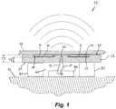
- FIG. 1is a side sectional elevation, taken along section line I-I of FIG. 4 , of a portion of a raised floor system incorporating surface-mounted resonators for wireless electrical power transmission in accordance with the present invention
- FIG. 2is an exploded side sectional elevation of the raised floor system and surface-mounted resonators of FIG. 1 ;
- FIG. 3is a perspective view of a substrate panel including rectangular recessed regions for receiving surface-mounted resonators for wireless electrical power transmission;
- FIG. 4is another perspective view of the substrate panel of FIG. 3 , shown with E-field resonators mounted in the recessed regions of the panel;
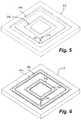
- FIG. 5is a perspective view of a substrate panel including two recessed regions in the shapes of squares having common centers, for receiving surface-mounted resonators for wireless electrical power transmission;
- FIG. 6is another perspective view of the substrate panel of FIG. 5 , shown with E-field resonators mounted in the recessed regions of the panel;
- FIG. 7is a perspective view of a substrate panel including two recessed regions in the shapes of concentric circles, for receiving surface-mounted resonators for wireless electrical power transmission;
- FIG. 8is a top plan view of the substrate panel of FIG. 7 , shown with E-field resonators mounted in the recessed regions of the panel;
- FIGS. 9A-9Care perspective views of other exemplary substrate panels with recessed regions for receiving surface-mounted resonators for wireless electrical power transmission.
- a wireless electrical power transmission system 10includes a panel 12 defining one or more recessed areas 14 , such as shown in FIGS. 1 and 2 .
- Wireless power transmitters or resonators 16are positioned in respective recessed areas 14 , and are electrically coupled to wiring 18 that passes through an opening or bore 20 formed in panel 12 .
- Panel 12has a first outer surface 22 and a second outer surface 24 located opposite the first outer surface 22 , and has a first thickness T 1 defined between the first and second outer surfaces 22 , 24 , and a second thickness T 2 defined between base surfaces 26 of recessed areas 14 ( FIGS. 2, 3, 5 and 7 ) and second outer surface 24 .
- the thickness of wireless power transmitters 16may be equal to the depth of recessed areas 14 (which depth may be calculated as second thickness T 2 subtracted from first thickness T 1 ), or may be less than the depth of recessed areas 14 , as shown. Where the thickness of wireless power transmitters 16 is less than the depth of recessed areas 14 , the remaining space above power transmitters 16 may be at least partially filled by protective panels or sheets 28 ( FIG. 2 ), thereby reducing the risk of damage to transmitters 16 , such as may be caused by dropped objects, heavy furniture or rolling carts, and the like, particularly in flooring applications.
- panel 12is a structural substrate that forms the upper structural layer of a raised flooring system, which includes structural support elements or spacers 30 that may form part of a framework resting on a substantially solid base surface 32 .
- panel 12 and the associated wireless electrical power transmission system 10may be adapted for use in raised floor systems like those described in commonly-owned U.S. Pat. Nos. 7,878,845 and 7,183,504, which are both hereby incorporated herein by reference in their entireties.
- Panel 12may be manufactured by various materials, including ferrous metal, non-ferrous metal such as aluminum, wood or composite wood products (including medium density fiberboard or ‘MDF’), ceramic, concrete or composite concrete products (including concrete mixed with fibrous materials), and the like.
- MDFmedium density fiberboard
- Recessed areas 14may be molded directly into panel 12 during manufacturing, or may be formed or established in panel 12 after manufacturing, such as using a stamping or milling process.
- recessed area 14is formed as two generally rectangular recessed areas 14 a , 14 b that are joined at their respective bases by an intermediate recessed area or pass-through 14 c that forms a bight region of the overall U-shaped recessed area 14 , as best shown in FIGS. 3 and 4 .
- Wire opening 20extends through base surface 26 at intermediate recessed area 14 c , and through second outer surface 24 , so that wiring 18 can pass through panel 12 and into a chamber 34 that is partially bounded by second outer surface 24 , such as shown in FIGS. 1 and 2 .
- an alternative wire opening or borecould be arranged through the panel to exit somewhere other than through the second outer surface 24 , such as through a side edge of the panel or even though another location along the first outer surface 22 or base surface 26 .
- FIGS. 5, 6 and 9Couter square recessed areas 114 a surround inner square recessed areas 114 b , with an intermediate recess or pass-through 114 c formed between two adjacent corners, where a wire opening 120 is established.
- FIGS. 5, 6 and 9Couter square recessed areas 114 a surround inner square recessed areas 114 b , with an intermediate recess or pass-through 114 c formed between two adjacent corners, where a wire opening 120 is established.
- outer circular recessed areas 214 asurround inner circular recessed areas 214 b , with an intermediate recess or pass-through 214 c formed between the two areas where a wire opening 220 is established.
- Circular recessed areas 214 a , 214 bmay be concentric as shown, and square recessed areas 114 a , 114 b may share a common center as shown, but it will be appreciated that the recessed areas may be shaped and positioned to accommodate different shapes of wireless power transmitters (including square wireless power transmitters 116 a , 116 b and circular wireless power transmitters 216 a , 216 b ) and/or to concentrate wireless power transmission in desired areas of a given panel 12 , 112 , 212 .
- a power driver circuit 36is positioned in the hollow chamber 34 and is in electrical communication with the wiring 18 and with an electrical power source (such as a high voltage AC power circuit of a building).
- Power driver circuit 36is operable to receive high voltage AC power from the electrical power source and convert the high voltage AC power to a voltage and type that is suitable for use by the wireless power transmitter(s) 16 .
- Suitable power driver circuits and wireless power transmittersare available, for example, from Solace Power Inc. of St. Johns, Newfoundland, Canada (www.solace.ca).
- wireless electrical power transmission systemis primarily described herein as being for electric field (‘E-field’) resonant capacitive coupling power transmission, it will be appreciated that the principles of the present invention may be practiced using inductive coils or other wireless power transmission technologies.
- E-fieldelectric field
- wireless electrical power transmission system 10may further include one or more protective panels 28 configured for insertion into recessed area 14 above each wireless power transmitter 16 .
- Protective panels 28are preferably made of a non-ferrous material, such as non-ferrous metal, resinous plastic sheet material, molded resinous plastic, cardboard or MDF, wood or plywood, ceramic, a fiber-reinforced (e.g., Kevlar) resinous plastic, or the like, and are intended to resist damage to the wireless power transmitters 16 , such as from abrasion or from impacts and point pressures caused by heavy furniture, rolling carts, dropped objects, etc.
- a non-ferrous materialsuch as non-ferrous metal, resinous plastic sheet material, molded resinous plastic, cardboard or MDF, wood or plywood, ceramic, a fiber-reinforced (e.g., Kevlar) resinous plastic, or the like
- protective panels 28are sized and shaped for insertion into at least an upper region of recessed area 14 .
- protective panelsmay be sized to cover a substantial portion of the first outer surface 22 , or a substantial portion thereof.
- protective panels 28may be sufficiently thick so as to contact upper surfaces of wireless power transmitters 16 while being substantially flush with first outer surface 22 .
- adhesivesmay be applied to protective panels 28 to aid in securing them in place, and also to secure an aesthetic cover 38 , which may be a vinyl or synthetic tile, a carpet tile or carpet section, wood or composite wood product, concrete or ceramic or composite concrete panel or tile, gypsum board, or wallpaper, for example.
- the material and finished appearance of aesthetic cover 38may be chosen according to application, e.g., floor, wall (including repositionable room dividers), ceiling, or work surface such as a desktop or tabletop.
- the wireless electrical power transmission system of the present inventionallows for wireless electrical power transmitters to be used in combination with ferrous metals while limiting or substantially preventing shielding or blocking the wireless transmission of electrical power by ferrous metals.
- Other components of the systemsuch as a power driver circuit, may be positioned remotely from the transmitters and connected via wiring that passes through the substrate or panel in which the wireless transmitters are mounted.
- the systemmay be incorporated into floor structures, including raised flooring systems, or into walls, ceilings, work surfaces, and the like, while presenting a desired aesthetic appearance and having minimal aesthetic impact in an area, or none at all, as desired.
- work surfacesis not intended to be limiting, and such surfaces can range from tables or desks to countertops in homes or businesses, cabinets or cabinet shelves, fixed or portable shelves including book shelves, and the like.
Landscapes
- Engineering & Computer Science (AREA)
- Architecture (AREA)
- Civil Engineering (AREA)
- Structural Engineering (AREA)
- Power Engineering (AREA)
- Computer Networks & Wireless Communication (AREA)
- General Engineering & Computer Science (AREA)
- Floor Finish (AREA)
- Transmitters (AREA)
- Life Sciences & Earth Sciences (AREA)
- Wood Science & Technology (AREA)
- Chemical & Material Sciences (AREA)
- Ceramic Engineering (AREA)
Abstract
Description
Claims (18)
Priority Applications (1)
| Application Number | Priority Date | Filing Date | Title |
|---|---|---|---|
| US15/612,605US10988940B2 (en) | 2016-06-03 | 2017-06-02 | Surface-mounted resonators for wireless power |
Applications Claiming Priority (2)
| Application Number | Priority Date | Filing Date | Title |
|---|---|---|---|
| US201662345415P | 2016-06-03 | 2016-06-03 | |
| US15/612,605US10988940B2 (en) | 2016-06-03 | 2017-06-02 | Surface-mounted resonators for wireless power |
Publications (2)
| Publication Number | Publication Date |
|---|---|
| US20170350136A1 US20170350136A1 (en) | 2017-12-07 |
| US10988940B2true US10988940B2 (en) | 2021-04-27 |
Family
ID=60483031
Family Applications (1)
| Application Number | Title | Priority Date | Filing Date |
|---|---|---|---|
| US15/612,605Active2039-12-10US10988940B2 (en) | 2016-06-03 | 2017-06-02 | Surface-mounted resonators for wireless power |
Country Status (3)
| Country | Link |
|---|---|
| US (1) | US10988940B2 (en) |
| CA (1) | CA2969439C (en) |
| MX (1) | MX393718B (en) |
Cited By (2)
| Publication number | Priority date | Publication date | Assignee | Title |
|---|---|---|---|---|
| WO2023033536A1 (en)* | 2021-09-01 | 2023-03-09 | 네이버랩스 주식회사 | Access floor equipped with system for wireless charging of robot and building including same |
| US11631995B2 (en)* | 2019-03-07 | 2023-04-18 | Hubbell Incorporated | Inductive power transfer |
Families Citing this family (3)
| Publication number | Priority date | Publication date | Assignee | Title |
|---|---|---|---|---|
| US10594095B2 (en) | 2013-03-15 | 2020-03-17 | Legrand Sa | Modular low profile raceway to provide power and/or data connectivity |
| WO2018041907A1 (en)* | 2016-08-31 | 2018-03-08 | Tarkett Gdl | Surface covering element for integrating an electrically powered electronic device into a surface covering of a building |
| DE102017119425A1 (en)* | 2017-02-01 | 2018-08-02 | <BARIT>(R) - Kunstharz-BELAGSTECHNIK GmbH | Floor covering with at least one electrical component and electrical component for a floor covering |
Citations (148)
| Publication number | Priority date | Publication date | Assignee | Title |
|---|---|---|---|---|
| US4372629A (en) | 1980-11-10 | 1983-02-08 | Stow/Davis Furniture Company | Combination wire enclosure and wire |
| US4551577A (en) | 1983-07-25 | 1985-11-05 | Byrne Norman R | Retractable power center |
| US4747788A (en) | 1987-01-28 | 1988-05-31 | Byrne Norman R | Manually operable retractable power center |
| US4984982A (en) | 1989-07-28 | 1991-01-15 | Amp Incorporated | Retractable access flooring module |
| US5171159A (en) | 1990-08-22 | 1992-12-15 | Byrne Norman R | Electrical interconnection assembly |
| US5575668A (en) | 1995-10-06 | 1996-11-19 | Timmerman; Paul | Temporary power/data tap |
| US5709156A (en) | 1995-06-07 | 1998-01-20 | Krueger International, Inc. | Flip-up electrical and communications device for use in combination with a worksurface |
| US5959433A (en) | 1997-08-22 | 1999-09-28 | Centurion Intl., Inc. | Universal inductive battery charger system |
| US5980279A (en) | 1997-09-25 | 1999-11-09 | Nienkamper Furniture & Accessories Inc. | Recessed electrical receptacle and work surface |
| US6028267A (en) | 1997-04-15 | 2000-02-22 | Byrne; Norman R. | Rotatable power center system |
| US6028413A (en) | 1997-09-19 | 2000-02-22 | Perdix Oy | Charging device for batteries in a mobile electrical device |
| US6036516A (en) | 1995-12-11 | 2000-03-14 | Byrne; Norman R. | Electrical interconnection assembly with additional outlet receptacles |
| US6046405A (en) | 1996-07-30 | 2000-04-04 | Obermann; Richard | Pop-up electrical receptacle assembly |
| US6290518B1 (en) | 1999-09-14 | 2001-09-18 | Norman R. Byrne | Rotatable power and data center with storage area |
| US6379182B1 (en) | 1998-11-27 | 2002-04-30 | Norman R. Byrne | Energy center with interchangeable support bases |
| US6436299B1 (en) | 1999-06-21 | 2002-08-20 | Amway Corporation | Water treatment system with an inductively coupled ballast |
| US20020171335A1 (en) | 2001-05-17 | 2002-11-21 | Wolfgang Held | Furniture drawer |
| US20030048254A1 (en) | 2001-09-07 | 2003-03-13 | Shih-Sheng Huang | Wireless peripherals charged by electromagnetic induction |
| US20030202317A1 (en) | 2002-03-25 | 2003-10-30 | Ben Jans | Desk housing upgradable and expandable computer, network and multimedia systems |
| US20040026998A1 (en) | 2002-07-24 | 2004-02-12 | Henriott Jay M. | Low voltage electrified furniture unit |
| US6756697B2 (en) | 2001-04-26 | 2004-06-29 | Denso Corporation | Mounting structure including communication system for transmitting multiplex control signal to vehicle electrical devices |
| US20040150934A1 (en) | 2003-02-04 | 2004-08-05 | Baarman David W. | Adapter |
| US20040189246A1 (en) | 2002-12-23 | 2004-09-30 | Claudiu Bulai | System and method for inductive charging a wireless mouse |
| US6803744B1 (en) | 1999-11-01 | 2004-10-12 | Anthony Sabo | Alignment independent and self aligning inductive power transfer system |
| US20050068019A1 (en) | 2003-09-30 | 2005-03-31 | Sharp Kabushiki Kaisha | Power supply system |
| US6967462B1 (en) | 2003-06-05 | 2005-11-22 | Nasa Glenn Research Center | Charging of devices by microwave power beaming |
| US6979209B2 (en) | 2003-01-29 | 2005-12-27 | Krueger International, Inc. | Biased utility receptacle assembly |
| US7183504B2 (en) | 2001-02-06 | 2007-02-27 | Byrne Norman R | Electrical floor access module system |
| US7212414B2 (en) | 1999-06-21 | 2007-05-01 | Access Business Group International, Llc | Adaptive inductive power supply |
| US7222031B2 (en) | 2001-03-13 | 2007-05-22 | British Telecommunications Public Limited Company | Power supply for tetherless workstations |
| US7233222B2 (en) | 1999-06-21 | 2007-06-19 | Access Business Group International Llc | Inductively powered apparatus |
| US20070182367A1 (en) | 2006-01-31 | 2007-08-09 | Afshin Partovi | Inductive power source and charging system |
| US7262700B2 (en) | 2005-03-10 | 2007-08-28 | Microsoft Corporation | Inductive powering surface for powering portable devices |
| US20070279002A1 (en) | 2006-06-01 | 2007-12-06 | Afshin Partovi | Power source, charging system, and inductive receiver for mobile devices |
| US20080001572A9 (en) | 1999-06-21 | 2008-01-03 | Baarman David W | Vehicle interface |
| US20080079392A1 (en) | 2006-09-29 | 2008-04-03 | Access Business Group International Llc | System and method for inductively charging a battery |
| US7355150B2 (en) | 2006-03-23 | 2008-04-08 | Access Business Group International Llc | Food preparation system with inductive power |
| US20080121147A1 (en) | 2006-11-29 | 2008-05-29 | Doug Mockett & Company, Inc. | Power and data station |
| US7392068B2 (en) | 2002-03-01 | 2008-06-24 | Mobilewise | Alternative wirefree mobile device power supply method and system with free positioning |
| US20080166965A1 (en) | 2007-01-04 | 2008-07-10 | Powercast Corporation | Wirelessly powered specialty lighting, motion, sound |
| US7399202B2 (en) | 2002-03-01 | 2008-07-15 | Tal Dayan | Wirefree mobile device power supply method & system with free positioning |
| US20080169910A1 (en) | 2007-01-05 | 2008-07-17 | Powercast Corporation | Implementation of a wireless power transmitter and method |
| US20080200050A1 (en) | 2005-06-13 | 2008-08-21 | Byrne Norman R | One Touch Pivoting Expandable Power and Data Center |
| US7443057B2 (en) | 2004-11-29 | 2008-10-28 | Patrick Nunally | Remote power charging of electronic devices |
| US7465178B2 (en) | 2005-05-04 | 2008-12-16 | Byrne Norman R | Raceway with multi-positionable receptacle blocks |
| US20090045772A1 (en) | 2007-06-11 | 2009-02-19 | Nigelpower, Llc | Wireless Power System and Proximity Effects |
| US20090096413A1 (en) | 2006-01-31 | 2009-04-16 | Mojo Mobility, Inc. | System and method for inductive charging of portable devices |
| US20090212638A1 (en) | 2008-02-25 | 2009-08-27 | L & P Property Management Company | Inductively coupled work surfaces |
| US20090212636A1 (en) | 2008-01-10 | 2009-08-27 | Nigel Power Llc | Wireless desktop IT environment |
| US20090230777A1 (en) | 2008-03-13 | 2009-09-17 | Access Business Group International Llc | Inductive power supply system with multiple coil primary |
| US20090271048A1 (en) | 2008-04-28 | 2009-10-29 | Masataka Wakamatsu | Power Transmitting Apparatus, Power Transmission Method, Program, and Power Transmission System |
| US20090278494A1 (en) | 2008-03-03 | 2009-11-12 | Mitch Randall | Universal electrical interface for providing power to mobile devices |
| US7633263B2 (en) | 2006-08-11 | 2009-12-15 | Sanyo Electric Co., Ltd. | Battery charger |
| US20100007307A1 (en) | 2008-07-09 | 2010-01-14 | Access Business Group International Llc | Wireless charging system |
| US20100038970A1 (en) | 2008-04-21 | 2010-02-18 | Nigel Power, Llc | Short Range Efficient Wireless Power Transfer |
| US20100052431A1 (en) | 2008-09-02 | 2010-03-04 | Sony Corporation | Non-contact power transmission device |
| US7674119B1 (en) | 1997-10-16 | 2010-03-09 | Mccarthy David G | Retractable receptacle for furniture |
| US20100127660A1 (en) | 2008-08-19 | 2010-05-27 | Qualcomm Incorporated | Wireless power transmission for portable wireless power charging |
| US7736178B2 (en) | 2005-06-13 | 2010-06-15 | Byrne Norman R | Expandable power and data center adapted for use with multiple mounts |
| US20100187913A1 (en) | 2008-08-20 | 2010-07-29 | Smith Joshua R | Wireless power transfer apparatus and method thereof |
| US20100201201A1 (en) | 2009-02-10 | 2010-08-12 | Qualcomm Incorporated | Wireless power transfer in public places |
| US20100244584A1 (en) | 2007-10-09 | 2010-09-30 | Powermat Ltd. | Inductive power providing system having moving outlets |
| US20100290215A1 (en) | 2009-05-12 | 2010-11-18 | Kimball International, Inc. | Furniture with wireless power |
| US20100308665A1 (en) | 2007-09-18 | 2010-12-09 | Powerkiss Oy | Energy transfer arrangement and method |
| US20100321939A1 (en) | 2007-04-20 | 2010-12-23 | Bharat Patel | Lamp base with upgradeable recharging port and method |
| US7863861B2 (en) | 2002-05-13 | 2011-01-04 | Access Business Group International Llc | Contact-less power transfer |
| US20110006611A1 (en)* | 2009-01-06 | 2011-01-13 | Access Business Group International Llc | Inductive power supply |
| US7878845B2 (en) | 2005-05-03 | 2011-02-01 | Byrne Norman R | Electrical floor access module system |
| US7887113B2 (en) | 2007-07-11 | 2011-02-15 | Stryker Corporation | Powered patient support and fastening system with inductive based power system |
| US20110062789A1 (en) | 2009-09-16 | 2011-03-17 | L & P Property Management Company | Inductively coupled power module and circuit |
| US20110121660A1 (en) | 2008-06-02 | 2011-05-26 | Powermat Ltd. | Appliance mounted power outlets |
| USD639244S1 (en) | 2005-04-26 | 2011-06-07 | Byrne Norman R | One touch and expandable power and data center |
| US20110175544A1 (en) | 2010-01-15 | 2011-07-21 | Jung-Chang Jong | Multifunctional Illuminating Lamp |
| US20110193417A1 (en) | 2010-02-05 | 2011-08-11 | Sony Corporation | Wireless power transmission apparatus |
| US20110241607A1 (en) | 2010-04-06 | 2011-10-06 | Garmin Ltd. | Electronic device with integral inductive charging station |
| US20110241614A1 (en) | 2010-03-30 | 2011-10-06 | Winharbor Technology Co., Ltd. | Notebook capable of wireless charging |
| US20110248575A1 (en) | 2010-04-08 | 2011-10-13 | Samsung Electronics Co., Ltd. | Television system with wireless power transmission function, television set, and set-top box |
| US20110260548A1 (en) | 2009-10-30 | 2011-10-27 | Tdk Corporation | Wireless power feeder, wireless power transmission system, and table and table lamp using the same |
| US20110305056A1 (en) | 2004-10-01 | 2011-12-15 | Tseng-Lu Chien | Desk top item with led means has usb-unit(s) or usb-module to charge other electric or digital data device(s) |
| US8106539B2 (en) | 2008-09-27 | 2012-01-31 | Witricity Corporation | Wireless energy transfer for refrigerator application |
| US20120113645A1 (en) | 2010-11-05 | 2012-05-10 | Wen-Yung Liao | Charging device and associated electrical appliances |
| US20120113576A1 (en) | 2010-11-05 | 2012-05-10 | Emily Cooper | Extendable wireless power delivery for small devices |
| US20120117730A1 (en) | 2006-06-28 | 2012-05-17 | Stryker Corporation | Patient support with wireless data and/or energy transfer |
| US20120153731A9 (en) | 2008-05-13 | 2012-06-21 | Qualcomm Incorporated | Wireless power transfer for furnishings and building elements |
| US20120170292A1 (en) | 2010-12-30 | 2012-07-05 | Leviton Manufacturing Company, Inc | Illuminated receptacle |
| US20120206097A1 (en) | 2007-12-21 | 2012-08-16 | Cynetic Designs Ltd. | Inductively coupled power and data transmission system |
| US20120228953A1 (en) | 2008-09-27 | 2012-09-13 | Kesler Morris P | Tunable wireless energy transfer for furniture applications |
| US20120235474A1 (en) | 2010-09-14 | 2012-09-20 | Joseph Mannino | Windshield embedded power coil for wireless charging |
| US8287292B2 (en) | 2005-06-13 | 2012-10-16 | Byrne Norman R | One touch pivoting expandable power and data center |
| US20120261998A1 (en) | 2011-04-14 | 2012-10-18 | Sony Corporation | Power control apparatus, power control method, and program |
| US8295036B2 (en) | 2007-06-11 | 2012-10-23 | Byrne Norman R | Expandable power and data center with latching mechanism |
| CN202552802U (en) | 2012-04-21 | 2012-11-28 | 林海 | Multifunctional dining table |
| US20120299539A1 (en) | 2011-05-25 | 2012-11-29 | Neil Jones | Light with integrated inductive charger base station |
| US20120312196A1 (en) | 2011-06-08 | 2012-12-13 | Newkirk David C | Overbed table with wireless power transfer |
| US20130049482A1 (en) | 2009-09-28 | 2013-02-28 | Powermat Ltd. | System and method for regulating inductive power transmission |
| US20130057203A1 (en) | 2011-03-01 | 2013-03-07 | Neil Jones | Assembly for mounting an inductive charger base station to a furniture work surface |
| US8395353B2 (en) | 2011-01-04 | 2013-03-12 | Primax Electronics, Ltd. | Wireless charging transmitter for portable electronic device |
| US20130062964A1 (en) | 2011-09-13 | 2013-03-14 | Samsung Electronics Co., Ltd. | Wireless electromagnetic receiver and wireless power transfer system |
| US20130062965A1 (en) | 2011-09-13 | 2013-03-14 | Samsung Electronics Co., Ltd., | Wireless electromagnetic receiver and wireless power transfer system |
| US8398408B1 (en) | 2009-02-25 | 2013-03-19 | Sonosite, Inc. | Charging station for cordless ultrasound cart |
| US20130119777A1 (en)* | 2011-11-03 | 2013-05-16 | Shaw Industries Group | Wireless energy transfer systems |
| US8444432B2 (en) | 2009-06-15 | 2013-05-21 | Norman R. Byrne | Power and data adapter assembly |
| US8456038B2 (en) | 2007-09-25 | 2013-06-04 | Powermat Technologies, Ltd | Adjustable inductive power transmission platform |
| US20130141038A1 (en) | 2011-12-01 | 2013-06-06 | James J. Papa | Energy distribution device for distributing an energy signal within a home |
| US8480429B2 (en) | 2005-06-13 | 2013-07-09 | Norman R. Byrne | Power data housing |
| US20130175986A1 (en) | 2010-10-06 | 2013-07-11 | Hewlett-Packard Development Company ,L.P. | Wireless electronic device docking system |
| US8497601B2 (en) | 2008-09-27 | 2013-07-30 | Witricity Corporation | Wireless energy transfer converters |
| WO2013112185A2 (en) | 2011-03-03 | 2013-08-01 | Kimball International, Inc. | Wirelessly powered furniture |
| US20130200717A1 (en) | 2012-02-07 | 2013-08-08 | Jordan T. Bourilkov | Wireless Power Transfer Using Separately Tunable Resonators |
| US20130207478A1 (en) | 2009-05-12 | 2013-08-15 | Kimball International, Inc. | Furniture with wireless power |
| US8559172B2 (en) | 2008-05-02 | 2013-10-15 | Norman R. Byrne | Docking station |
| US8558661B2 (en) | 2007-06-14 | 2013-10-15 | Omnilectric, Inc. | Wireless power transmission system |
| US20130285606A1 (en) | 2011-01-10 | 2013-10-31 | Powermat Technologies Ltd. | System for transferring power inductively to items within a container |
| US8581444B2 (en) | 2009-10-30 | 2013-11-12 | Tdk Corporation | Wireless power feeder, wireless power transmission system, and table and table lamp using the same |
| US8616921B2 (en) | 2011-06-13 | 2013-12-31 | Norman R. Byrne | Floor runner with electrical outlets |
| US20140021798A1 (en)* | 2012-07-17 | 2014-01-23 | Witricity Corporation | Wireless energy transfer with repeater resonators |
| US8690590B2 (en) | 2007-06-11 | 2014-04-08 | Norman R. Byrne | Power and data component mounted on a movable carriage and a movable cover with a damper |
| US8721124B2 (en) | 2011-06-12 | 2014-05-13 | Norman R. Byrne | Retractable light assembly |
| US20140197755A1 (en)* | 2011-08-16 | 2014-07-17 | Koninklijke Philips N.V. | An acoustic ceiling for a capacitive power transfer system |
| US20140361633A1 (en) | 2011-09-21 | 2014-12-11 | Panasonic Corporation | Non-contact power supply system |
| US8937407B2 (en) | 2009-09-24 | 2015-01-20 | Norman R. Byrne | Worksurface power transfer |
| US8944266B2 (en) | 2008-09-23 | 2015-02-03 | Dirtt Environmental Solutions Ltd. | Floor-mount service container and lid |
| US8951054B2 (en) | 2010-06-11 | 2015-02-10 | Norman R. Byrne | Retractable power tap with low voltage cordless capability |
| US20150048687A1 (en)* | 2013-07-19 | 2015-02-19 | Coremate Technical Co., Ltd. | Multi-function wireless power induction mousepad |
| US20150091389A1 (en)* | 2013-09-30 | 2015-04-02 | Norman R. Byrne | Wireless power for portable articles |
| US20150249343A1 (en) | 2014-03-03 | 2015-09-03 | The Wiremold Company | Wireless power stations |
| US9148006B2 (en) | 2013-05-03 | 2015-09-29 | Norman R. Byrne | Interchangeable base system |
| US20160025316A1 (en) | 2004-10-01 | 2016-01-28 | Tseng-Lu Chien | Multifunctional desktop system |
| US20160022030A1 (en) | 2014-07-28 | 2016-01-28 | Group Dekko, Inc. | Desktop receptacle with flip cover |
| US9312673B2 (en) | 2013-06-03 | 2016-04-12 | Norman R. Byrne | Low voltage power receptacle |
| US20160153650A1 (en) | 2010-11-19 | 2016-06-02 | Tseng-Lu Chien | Led desk light having more than one function |
| US20160233711A1 (en) | 2013-03-20 | 2016-08-11 | Halo International SEZC Ltd. | Power charging kit with wireless and direct charging connectivity |
| US9438070B2 (en) | 2013-09-30 | 2016-09-06 | Norman R. Byrne | Articles with electrical charging surfaces |
| US20170085130A1 (en)* | 2015-09-23 | 2017-03-23 | Qualcomm Incorporated | Multifilament transmitter coupler with current sharing |
| US9605455B2 (en) | 2013-04-24 | 2017-03-28 | Compx International Inc. | Combination slam latch and cam lock adapter |
| US9653948B2 (en) | 2011-09-07 | 2017-05-16 | Solace Power Inc. | Wireless resonant electric field power transfer system and method using high Q-factor coils |
| US20170156490A1 (en) | 2015-12-04 | 2017-06-08 | Group Dekko, Inc. | Desktop receptacle with rigid support |
| US20170177031A1 (en) | 2015-06-12 | 2017-06-22 | Scott LESIZZA | Drawer, drawer insert and workstation with electronic panel for charging and synching |
| US20170224103A1 (en) | 2016-02-08 | 2017-08-10 | Group Dekko, Inc. | Desktop receptacle with hinged cover |
| US20170237295A1 (en)* | 2014-08-20 | 2017-08-17 | Toyota Jidosha Kabushiki Kaisha | Power transmission device, method for manufacturing the same, power reception device and method for manufacturing the same |
| US20170258246A1 (en) | 2014-09-03 | 2017-09-14 | Apple Inc. | Table display system |
| US20170317458A1 (en) | 2016-05-02 | 2017-11-02 | Norman R. Byrne | Electrical power unit with wireless charging |
| US20170317533A1 (en) | 2016-05-02 | 2017-11-02 | Norman R. Byrne | Worksurface-mounted wireless charging grommet |
| US9979206B2 (en) | 2012-09-07 | 2018-05-22 | Solace Power Inc. | Wireless electric field power transfer system, method, transmitter and receiver therefor |
| US20180191178A1 (en) | 2017-01-05 | 2018-07-05 | Norman R. Byrne | Furniture with embedded wireless power transmission |
| US10033225B2 (en) | 2012-09-07 | 2018-07-24 | Solace Power Inc. | Wireless electric field power transmission system, transmitter and receiver therefor and method of wirelessly transferring power |
| US10116094B2 (en) | 2016-08-12 | 2018-10-30 | Norman R. Byrne | Data-secure connector with indicator |
| US20190140480A1 (en) | 2017-11-06 | 2019-05-09 | Solace Power Inc. | Wireless power transfer systems, methods and transmitters therefor |
- 2017
- 2017-06-02USUS15/612,605patent/US10988940B2/enactiveActive
- 2017-06-02CACA2969439Apatent/CA2969439C/enactiveActive
- 2017-06-05MXMX2017007151Apatent/MX393718B/enunknown
Patent Citations (162)
| Publication number | Priority date | Publication date | Assignee | Title |
|---|---|---|---|---|
| US4372629A (en) | 1980-11-10 | 1983-02-08 | Stow/Davis Furniture Company | Combination wire enclosure and wire |
| US4551577A (en) | 1983-07-25 | 1985-11-05 | Byrne Norman R | Retractable power center |
| US4747788A (en) | 1987-01-28 | 1988-05-31 | Byrne Norman R | Manually operable retractable power center |
| US4984982A (en) | 1989-07-28 | 1991-01-15 | Amp Incorporated | Retractable access flooring module |
| US5171159A (en) | 1990-08-22 | 1992-12-15 | Byrne Norman R | Electrical interconnection assembly |
| US5709156A (en) | 1995-06-07 | 1998-01-20 | Krueger International, Inc. | Flip-up electrical and communications device for use in combination with a worksurface |
| US5575668A (en) | 1995-10-06 | 1996-11-19 | Timmerman; Paul | Temporary power/data tap |
| US6036516A (en) | 1995-12-11 | 2000-03-14 | Byrne; Norman R. | Electrical interconnection assembly with additional outlet receptacles |
| US6046405A (en) | 1996-07-30 | 2000-04-04 | Obermann; Richard | Pop-up electrical receptacle assembly |
| US6028267A (en) | 1997-04-15 | 2000-02-22 | Byrne; Norman R. | Rotatable power center system |
| US5959433A (en) | 1997-08-22 | 1999-09-28 | Centurion Intl., Inc. | Universal inductive battery charger system |
| US6028413A (en) | 1997-09-19 | 2000-02-22 | Perdix Oy | Charging device for batteries in a mobile electrical device |
| US5980279A (en) | 1997-09-25 | 1999-11-09 | Nienkamper Furniture & Accessories Inc. | Recessed electrical receptacle and work surface |
| US7674119B1 (en) | 1997-10-16 | 2010-03-09 | Mccarthy David G | Retractable receptacle for furniture |
| US6379182B1 (en) | 1998-11-27 | 2002-04-30 | Norman R. Byrne | Energy center with interchangeable support bases |
| US7233222B2 (en) | 1999-06-21 | 2007-06-19 | Access Business Group International Llc | Inductively powered apparatus |
| US20080001572A9 (en) | 1999-06-21 | 2008-01-03 | Baarman David W | Vehicle interface |
| US6436299B1 (en) | 1999-06-21 | 2002-08-20 | Amway Corporation | Water treatment system with an inductively coupled ballast |
| US7212414B2 (en) | 1999-06-21 | 2007-05-01 | Access Business Group International, Llc | Adaptive inductive power supply |
| US6290518B1 (en) | 1999-09-14 | 2001-09-18 | Norman R. Byrne | Rotatable power and data center with storage area |
| US6803744B1 (en) | 1999-11-01 | 2004-10-12 | Anthony Sabo | Alignment independent and self aligning inductive power transfer system |
| US7183504B2 (en) | 2001-02-06 | 2007-02-27 | Byrne Norman R | Electrical floor access module system |
| US7222031B2 (en) | 2001-03-13 | 2007-05-22 | British Telecommunications Public Limited Company | Power supply for tetherless workstations |
| US6756697B2 (en) | 2001-04-26 | 2004-06-29 | Denso Corporation | Mounting structure including communication system for transmitting multiplex control signal to vehicle electrical devices |
| US20020171335A1 (en) | 2001-05-17 | 2002-11-21 | Wolfgang Held | Furniture drawer |
| US20030048254A1 (en) | 2001-09-07 | 2003-03-13 | Shih-Sheng Huang | Wireless peripherals charged by electromagnetic induction |
| US7399202B2 (en) | 2002-03-01 | 2008-07-15 | Tal Dayan | Wirefree mobile device power supply method & system with free positioning |
| US7392068B2 (en) | 2002-03-01 | 2008-06-24 | Mobilewise | Alternative wirefree mobile device power supply method and system with free positioning |
| US20030202317A1 (en) | 2002-03-25 | 2003-10-30 | Ben Jans | Desk housing upgradable and expandable computer, network and multimedia systems |
| US7863861B2 (en) | 2002-05-13 | 2011-01-04 | Access Business Group International Llc | Contact-less power transfer |
| US20040026998A1 (en) | 2002-07-24 | 2004-02-12 | Henriott Jay M. | Low voltage electrified furniture unit |
| US20040189246A1 (en) | 2002-12-23 | 2004-09-30 | Claudiu Bulai | System and method for inductive charging a wireless mouse |
| US6979209B2 (en) | 2003-01-29 | 2005-12-27 | Krueger International, Inc. | Biased utility receptacle assembly |
| US20040150934A1 (en) | 2003-02-04 | 2004-08-05 | Baarman David W. | Adapter |
| US6967462B1 (en) | 2003-06-05 | 2005-11-22 | Nasa Glenn Research Center | Charging of devices by microwave power beaming |
| US20050068019A1 (en) | 2003-09-30 | 2005-03-31 | Sharp Kabushiki Kaisha | Power supply system |
| US20110305056A1 (en) | 2004-10-01 | 2011-12-15 | Tseng-Lu Chien | Desk top item with led means has usb-unit(s) or usb-module to charge other electric or digital data device(s) |
| US20160025316A1 (en) | 2004-10-01 | 2016-01-28 | Tseng-Lu Chien | Multifunctional desktop system |
| US7443057B2 (en) | 2004-11-29 | 2008-10-28 | Patrick Nunally | Remote power charging of electronic devices |
| US7262700B2 (en) | 2005-03-10 | 2007-08-28 | Microsoft Corporation | Inductive powering surface for powering portable devices |
| USD639244S1 (en) | 2005-04-26 | 2011-06-07 | Byrne Norman R | One touch and expandable power and data center |
| US7878845B2 (en) | 2005-05-03 | 2011-02-01 | Byrne Norman R | Electrical floor access module system |
| US7465178B2 (en) | 2005-05-04 | 2008-12-16 | Byrne Norman R | Raceway with multi-positionable receptacle blocks |
| US20080200050A1 (en) | 2005-06-13 | 2008-08-21 | Byrne Norman R | One Touch Pivoting Expandable Power and Data Center |
| US7736178B2 (en) | 2005-06-13 | 2010-06-15 | Byrne Norman R | Expandable power and data center adapted for use with multiple mounts |
| US8480429B2 (en) | 2005-06-13 | 2013-07-09 | Norman R. Byrne | Power data housing |
| US8287292B2 (en) | 2005-06-13 | 2012-10-16 | Byrne Norman R | One touch pivoting expandable power and data center |
| US20070182367A1 (en) | 2006-01-31 | 2007-08-09 | Afshin Partovi | Inductive power source and charging system |
| US20090096413A1 (en) | 2006-01-31 | 2009-04-16 | Mojo Mobility, Inc. | System and method for inductive charging of portable devices |
| US7355150B2 (en) | 2006-03-23 | 2008-04-08 | Access Business Group International Llc | Food preparation system with inductive power |
| US20070279002A1 (en) | 2006-06-01 | 2007-12-06 | Afshin Partovi | Power source, charging system, and inductive receiver for mobile devices |
| US20120117730A1 (en) | 2006-06-28 | 2012-05-17 | Stryker Corporation | Patient support with wireless data and/or energy transfer |
| US7633263B2 (en) | 2006-08-11 | 2009-12-15 | Sanyo Electric Co., Ltd. | Battery charger |
| US20080079392A1 (en) | 2006-09-29 | 2008-04-03 | Access Business Group International Llc | System and method for inductively charging a battery |
| US20080121147A1 (en) | 2006-11-29 | 2008-05-29 | Doug Mockett & Company, Inc. | Power and data station |
| US20080166965A1 (en) | 2007-01-04 | 2008-07-10 | Powercast Corporation | Wirelessly powered specialty lighting, motion, sound |
| US20080169910A1 (en) | 2007-01-05 | 2008-07-17 | Powercast Corporation | Implementation of a wireless power transmitter and method |
| US20100321939A1 (en) | 2007-04-20 | 2010-12-23 | Bharat Patel | Lamp base with upgradeable recharging port and method |
| US8690590B2 (en) | 2007-06-11 | 2014-04-08 | Norman R. Byrne | Power and data component mounted on a movable carriage and a movable cover with a damper |
| US20090045772A1 (en) | 2007-06-11 | 2009-02-19 | Nigelpower, Llc | Wireless Power System and Proximity Effects |
| US8295036B2 (en) | 2007-06-11 | 2012-10-23 | Byrne Norman R | Expandable power and data center with latching mechanism |
| US8558661B2 (en) | 2007-06-14 | 2013-10-15 | Omnilectric, Inc. | Wireless power transmission system |
| US7887113B2 (en) | 2007-07-11 | 2011-02-15 | Stryker Corporation | Powered patient support and fastening system with inductive based power system |
| US20100308665A1 (en) | 2007-09-18 | 2010-12-09 | Powerkiss Oy | Energy transfer arrangement and method |
| US8456038B2 (en) | 2007-09-25 | 2013-06-04 | Powermat Technologies, Ltd | Adjustable inductive power transmission platform |
| US20100259401A1 (en) | 2007-10-09 | 2010-10-14 | Powermat Ltd. | System and method for inductive power provision over an extended surface |
| US20100244584A1 (en) | 2007-10-09 | 2010-09-30 | Powermat Ltd. | Inductive power providing system having moving outlets |
| US8283812B2 (en) | 2007-10-09 | 2012-10-09 | Powermat Technologies, Ltd. | Inductive power providing system having moving outlets |
| US8624750B2 (en) | 2007-10-09 | 2014-01-07 | Powermat Technologies, Ltd. | System and method for inductive power provision over an extended surface |
| US20120206097A1 (en) | 2007-12-21 | 2012-08-16 | Cynetic Designs Ltd. | Inductively coupled power and data transmission system |
| US20090212636A1 (en) | 2008-01-10 | 2009-08-27 | Nigel Power Llc | Wireless desktop IT environment |
| US20130234481A1 (en) | 2008-02-25 | 2013-09-12 | L & P Property Management Company | Inductively coupled consoles |
| US20090212638A1 (en) | 2008-02-25 | 2009-08-27 | L & P Property Management Company | Inductively coupled work surfaces |
| US8421407B2 (en) | 2008-02-25 | 2013-04-16 | L & P Property Management Company | Inductively coupled work surfaces |
| US20090278494A1 (en) | 2008-03-03 | 2009-11-12 | Mitch Randall | Universal electrical interface for providing power to mobile devices |
| US20090230777A1 (en) | 2008-03-13 | 2009-09-17 | Access Business Group International Llc | Inductive power supply system with multiple coil primary |
| US20100038970A1 (en) | 2008-04-21 | 2010-02-18 | Nigel Power, Llc | Short Range Efficient Wireless Power Transfer |
| US20090271048A1 (en) | 2008-04-28 | 2009-10-29 | Masataka Wakamatsu | Power Transmitting Apparatus, Power Transmission Method, Program, and Power Transmission System |
| US8559172B2 (en) | 2008-05-02 | 2013-10-15 | Norman R. Byrne | Docking station |
| US8487478B2 (en) | 2008-05-13 | 2013-07-16 | Qualcomm Incorporated | Wireless power transfer for appliances and equipments |
| US20120153731A9 (en) | 2008-05-13 | 2012-06-21 | Qualcomm Incorporated | Wireless power transfer for furnishings and building elements |
| US20110121660A1 (en) | 2008-06-02 | 2011-05-26 | Powermat Ltd. | Appliance mounted power outlets |
| US8618695B2 (en) | 2008-06-02 | 2013-12-31 | Powermat Technologies, Ltd | Appliance mounted power outlets |
| US20100007307A1 (en) | 2008-07-09 | 2010-01-14 | Access Business Group International Llc | Wireless charging system |
| US20100127660A1 (en) | 2008-08-19 | 2010-05-27 | Qualcomm Incorporated | Wireless power transmission for portable wireless power charging |
| US20100187913A1 (en) | 2008-08-20 | 2010-07-29 | Smith Joshua R | Wireless power transfer apparatus and method thereof |
| US20100052431A1 (en) | 2008-09-02 | 2010-03-04 | Sony Corporation | Non-contact power transmission device |
| US8944266B2 (en) | 2008-09-23 | 2015-02-03 | Dirtt Environmental Solutions Ltd. | Floor-mount service container and lid |
| US8106539B2 (en) | 2008-09-27 | 2012-01-31 | Witricity Corporation | Wireless energy transfer for refrigerator application |
| US20120228953A1 (en) | 2008-09-27 | 2012-09-13 | Kesler Morris P | Tunable wireless energy transfer for furniture applications |
| US8497601B2 (en) | 2008-09-27 | 2013-07-30 | Witricity Corporation | Wireless energy transfer converters |
| US20110006611A1 (en)* | 2009-01-06 | 2011-01-13 | Access Business Group International Llc | Inductive power supply |
| US20100201201A1 (en) | 2009-02-10 | 2010-08-12 | Qualcomm Incorporated | Wireless power transfer in public places |
| US8398408B1 (en) | 2009-02-25 | 2013-03-19 | Sonosite, Inc. | Charging station for cordless ultrasound cart |
| US8262244B2 (en) | 2009-05-12 | 2012-09-11 | Kimball International, Inc. | Furniture with wireless power |
| US20100290215A1 (en) | 2009-05-12 | 2010-11-18 | Kimball International, Inc. | Furniture with wireless power |
| US20130207478A1 (en) | 2009-05-12 | 2013-08-15 | Kimball International, Inc. | Furniture with wireless power |
| US8061864B2 (en) | 2009-05-12 | 2011-11-22 | Kimball International, Inc. | Furniture with wireless power |
| US8444432B2 (en) | 2009-06-15 | 2013-05-21 | Norman R. Byrne | Power and data adapter assembly |
| US20110062789A1 (en) | 2009-09-16 | 2011-03-17 | L & P Property Management Company | Inductively coupled power module and circuit |
| US8482160B2 (en) | 2009-09-16 | 2013-07-09 | L & P Property Management Company | Inductively coupled power module and circuit |
| US8937407B2 (en) | 2009-09-24 | 2015-01-20 | Norman R. Byrne | Worksurface power transfer |
| US20130049482A1 (en) | 2009-09-28 | 2013-02-28 | Powermat Ltd. | System and method for regulating inductive power transmission |
| US8581444B2 (en) | 2009-10-30 | 2013-11-12 | Tdk Corporation | Wireless power feeder, wireless power transmission system, and table and table lamp using the same |
| US20110260548A1 (en) | 2009-10-30 | 2011-10-27 | Tdk Corporation | Wireless power feeder, wireless power transmission system, and table and table lamp using the same |
| US20110175544A1 (en) | 2010-01-15 | 2011-07-21 | Jung-Chang Jong | Multifunctional Illuminating Lamp |
| US20110193417A1 (en) | 2010-02-05 | 2011-08-11 | Sony Corporation | Wireless power transmission apparatus |
| US20110241614A1 (en) | 2010-03-30 | 2011-10-06 | Winharbor Technology Co., Ltd. | Notebook capable of wireless charging |
| US20110241607A1 (en) | 2010-04-06 | 2011-10-06 | Garmin Ltd. | Electronic device with integral inductive charging station |
| US20110248575A1 (en) | 2010-04-08 | 2011-10-13 | Samsung Electronics Co., Ltd. | Television system with wireless power transmission function, television set, and set-top box |
| US8951054B2 (en) | 2010-06-11 | 2015-02-10 | Norman R. Byrne | Retractable power tap with low voltage cordless capability |
| US20120235474A1 (en) | 2010-09-14 | 2012-09-20 | Joseph Mannino | Windshield embedded power coil for wireless charging |
| US20130175986A1 (en) | 2010-10-06 | 2013-07-11 | Hewlett-Packard Development Company ,L.P. | Wireless electronic device docking system |
| US20120113645A1 (en) | 2010-11-05 | 2012-05-10 | Wen-Yung Liao | Charging device and associated electrical appliances |
| US20120113576A1 (en) | 2010-11-05 | 2012-05-10 | Emily Cooper | Extendable wireless power delivery for small devices |
| US20160153650A1 (en) | 2010-11-19 | 2016-06-02 | Tseng-Lu Chien | Led desk light having more than one function |
| US20120170292A1 (en) | 2010-12-30 | 2012-07-05 | Leviton Manufacturing Company, Inc | Illuminated receptacle |
| US8395353B2 (en) | 2011-01-04 | 2013-03-12 | Primax Electronics, Ltd. | Wireless charging transmitter for portable electronic device |
| US20130285606A1 (en) | 2011-01-10 | 2013-10-31 | Powermat Technologies Ltd. | System for transferring power inductively to items within a container |
| US20130057203A1 (en) | 2011-03-01 | 2013-03-07 | Neil Jones | Assembly for mounting an inductive charger base station to a furniture work surface |
| WO2013112185A2 (en) | 2011-03-03 | 2013-08-01 | Kimball International, Inc. | Wirelessly powered furniture |
| US20120261998A1 (en) | 2011-04-14 | 2012-10-18 | Sony Corporation | Power control apparatus, power control method, and program |
| US20120299539A1 (en) | 2011-05-25 | 2012-11-29 | Neil Jones | Light with integrated inductive charger base station |
| US20120312196A1 (en) | 2011-06-08 | 2012-12-13 | Newkirk David C | Overbed table with wireless power transfer |
| US8721124B2 (en) | 2011-06-12 | 2014-05-13 | Norman R. Byrne | Retractable light assembly |
| US8616921B2 (en) | 2011-06-13 | 2013-12-31 | Norman R. Byrne | Floor runner with electrical outlets |
| US20140197755A1 (en)* | 2011-08-16 | 2014-07-17 | Koninklijke Philips N.V. | An acoustic ceiling for a capacitive power transfer system |
| US20190165612A1 (en) | 2011-09-07 | 2019-05-30 | Solace Power Inc. | Wireless electric field power transfer system, method, transmitter and receiver therefor |
| US9653948B2 (en) | 2011-09-07 | 2017-05-16 | Solace Power Inc. | Wireless resonant electric field power transfer system and method using high Q-factor coils |
| US20130062965A1 (en) | 2011-09-13 | 2013-03-14 | Samsung Electronics Co., Ltd., | Wireless electromagnetic receiver and wireless power transfer system |
| US20130062964A1 (en) | 2011-09-13 | 2013-03-14 | Samsung Electronics Co., Ltd. | Wireless electromagnetic receiver and wireless power transfer system |
| US20140361633A1 (en) | 2011-09-21 | 2014-12-11 | Panasonic Corporation | Non-contact power supply system |
| US20130119777A1 (en)* | 2011-11-03 | 2013-05-16 | Shaw Industries Group | Wireless energy transfer systems |
| US20130141038A1 (en) | 2011-12-01 | 2013-06-06 | James J. Papa | Energy distribution device for distributing an energy signal within a home |
| US20130200717A1 (en) | 2012-02-07 | 2013-08-08 | Jordan T. Bourilkov | Wireless Power Transfer Using Separately Tunable Resonators |
| CN202552802U (en) | 2012-04-21 | 2012-11-28 | 林海 | Multifunctional dining table |
| US20140021798A1 (en)* | 2012-07-17 | 2014-01-23 | Witricity Corporation | Wireless energy transfer with repeater resonators |
| US9979206B2 (en) | 2012-09-07 | 2018-05-22 | Solace Power Inc. | Wireless electric field power transfer system, method, transmitter and receiver therefor |
| US10033225B2 (en) | 2012-09-07 | 2018-07-24 | Solace Power Inc. | Wireless electric field power transmission system, transmitter and receiver therefor and method of wirelessly transferring power |
| US20160233711A1 (en) | 2013-03-20 | 2016-08-11 | Halo International SEZC Ltd. | Power charging kit with wireless and direct charging connectivity |
| US9605455B2 (en) | 2013-04-24 | 2017-03-28 | Compx International Inc. | Combination slam latch and cam lock adapter |
| US9148006B2 (en) | 2013-05-03 | 2015-09-29 | Norman R. Byrne | Interchangeable base system |
| US9312673B2 (en) | 2013-06-03 | 2016-04-12 | Norman R. Byrne | Low voltage power receptacle |
| US20150048687A1 (en)* | 2013-07-19 | 2015-02-19 | Coremate Technical Co., Ltd. | Multi-function wireless power induction mousepad |
| US9484751B2 (en) | 2013-09-30 | 2016-11-01 | Norman R. Byrne | Wireless power for portable articles |
| US9438070B2 (en) | 2013-09-30 | 2016-09-06 | Norman R. Byrne | Articles with electrical charging surfaces |
| US10050473B2 (en) | 2013-09-30 | 2018-08-14 | Norman R. Byrne | Articles with electrical charging surfaces |
| US20150091389A1 (en)* | 2013-09-30 | 2015-04-02 | Norman R. Byrne | Wireless power for portable articles |
| US20150249343A1 (en) | 2014-03-03 | 2015-09-03 | The Wiremold Company | Wireless power stations |
| US20160022030A1 (en) | 2014-07-28 | 2016-01-28 | Group Dekko, Inc. | Desktop receptacle with flip cover |
| US20170237295A1 (en)* | 2014-08-20 | 2017-08-17 | Toyota Jidosha Kabushiki Kaisha | Power transmission device, method for manufacturing the same, power reception device and method for manufacturing the same |
| US20170258246A1 (en) | 2014-09-03 | 2017-09-14 | Apple Inc. | Table display system |
| US10424942B2 (en) | 2014-09-05 | 2019-09-24 | Solace Power Inc. | Wireless electric field power transfer system, method, transmitter and receiver therefor |
| US20170177031A1 (en) | 2015-06-12 | 2017-06-22 | Scott LESIZZA | Drawer, drawer insert and workstation with electronic panel for charging and synching |
| US20170085130A1 (en)* | 2015-09-23 | 2017-03-23 | Qualcomm Incorporated | Multifilament transmitter coupler with current sharing |
| US20170156490A1 (en) | 2015-12-04 | 2017-06-08 | Group Dekko, Inc. | Desktop receptacle with rigid support |
| US20170224103A1 (en) | 2016-02-08 | 2017-08-10 | Group Dekko, Inc. | Desktop receptacle with hinged cover |
| US20170317533A1 (en) | 2016-05-02 | 2017-11-02 | Norman R. Byrne | Worksurface-mounted wireless charging grommet |
| US20170317458A1 (en) | 2016-05-02 | 2017-11-02 | Norman R. Byrne | Electrical power unit with wireless charging |
| US10116094B2 (en) | 2016-08-12 | 2018-10-30 | Norman R. Byrne | Data-secure connector with indicator |
| US20180191178A1 (en) | 2017-01-05 | 2018-07-05 | Norman R. Byrne | Furniture with embedded wireless power transmission |
| US20190140480A1 (en) | 2017-11-06 | 2019-05-09 | Solace Power Inc. | Wireless power transfer systems, methods and transmitters therefor |
Cited By (4)
| Publication number | Priority date | Publication date | Assignee | Title |
|---|---|---|---|---|
| US11631995B2 (en)* | 2019-03-07 | 2023-04-18 | Hubbell Incorporated | Inductive power transfer |
| US12255466B2 (en) | 2019-03-07 | 2025-03-18 | Hubbell Incorporated | Inductive power transfer |
| WO2023033536A1 (en)* | 2021-09-01 | 2023-03-09 | 네이버랩스 주식회사 | Access floor equipped with system for wireless charging of robot and building including same |
| US20240198829A1 (en)* | 2021-09-01 | 2024-06-20 | Naver Labs Corporation | Access floor equipped with a system for wireless charging of a robot and a building including same |
Also Published As
| Publication number | Publication date |
|---|---|
| CA2969439C (en) | 2022-11-01 |
| CA2969439A1 (en) | 2017-12-03 |
| MX2017007151A (en) | 2018-08-29 |
| US20170350136A1 (en) | 2017-12-07 |
| MX393718B (en) | 2025-03-24 |
Similar Documents
| Publication | Publication Date | Title |
|---|---|---|
| US10988940B2 (en) | Surface-mounted resonators for wireless power | |
| US7469512B2 (en) | Fabricated wall system | |
| US3352615A (en) | Connecting structure | |
| AU2010237606B2 (en) | A noise attenuating and vibration dampening pedestal for an access floor assembly | |
| US20170226749A1 (en) | Cork-based tile for privacy apparatuses and method of making and using the same | |
| WO2005076798A3 (en) | Sill plate | |
| US8281542B2 (en) | Mechanisms for locking and removing flush mounted inserts | |
| EP1887910B1 (en) | Assembly between a side member and a rear panel of a piece of furniture | |
| WO2010090828A2 (en) | Flush mounting apparatus and methods using component cover | |
| WO2012166720A1 (en) | Recessed reveal wall panel system | |
| US6676231B1 (en) | Modular furniture system | |
| US11264165B2 (en) | Decorative panel comprising an inductive coil | |
| US20090064627A1 (en) | Flush Mount Panels With Interconnects | |
| US8667645B2 (en) | Attachment glider | |
| CA2751353A1 (en) | Metal top computer room access floor panel | |
| US6840591B2 (en) | Metallic toe kick for wooden cabinets | |
| US20210186210A1 (en) | Modular casework constructions using solid-surface materials | |
| US7412801B2 (en) | Sound absorbing panel | |
| US2477466A (en) | Table top | |
| EP1273732B1 (en) | A composite panel including a wood surface for making furniture pieces, walls, doors and the like | |
| US20220338632A1 (en) | Construction panel with modular lattice/composite design | |
| AU2013286809B2 (en) | A stone worktop system, a composite stone board, and a method of manufacturing a composite stone board | |
| EP1795338A1 (en) | Composite material coated panel for use in the building and furnishing sector | |
| CN209825860U (en) | Cabinet | |
| ITUD20130017A1 (en) | MULTIFUNCTION TABLE |
Legal Events
| Date | Code | Title | Description |
|---|---|---|---|
| AS | Assignment | Owner name:BYRNE, NORMAN R., MICHIGAN Free format text:ASSIGNMENT OF ASSIGNORS INTEREST;ASSIGNOR:BYRNE ELECTRICAL SPECIALISTS, INC.;REEL/FRAME:043144/0538 Effective date:20170707 Owner name:BYRNE ELECTRICAL SPECIALISTS, INC., MICHIGAN Free format text:ASSIGNMENT OF ASSIGNORS INTEREST;ASSIGNORS:BYRNE, NORMAN R.;MAHER, PETER J.;WARWICK, TIMOTHY J.;AND OTHERS;SIGNING DATES FROM 20170606 TO 20170707;REEL/FRAME:043144/0502 | |
| STPP | Information on status: patent application and granting procedure in general | Free format text:DOCKETED NEW CASE - READY FOR EXAMINATION | |
| STPP | Information on status: patent application and granting procedure in general | Free format text:NON FINAL ACTION MAILED | |
| STPP | Information on status: patent application and granting procedure in general | Free format text:RESPONSE TO NON-FINAL OFFICE ACTION ENTERED AND FORWARDED TO EXAMINER | |
| STPP | Information on status: patent application and granting procedure in general | Free format text:RESPONSE AFTER FINAL ACTION FORWARDED TO EXAMINER | |
| STPP | Information on status: patent application and granting procedure in general | Free format text:NOTICE OF ALLOWANCE MAILED -- APPLICATION RECEIVED IN OFFICE OF PUBLICATIONS | |
| STPP | Information on status: patent application and granting procedure in general | Free format text:NOTICE OF ALLOWANCE MAILED -- APPLICATION RECEIVED IN OFFICE OF PUBLICATIONS | |
| STPP | Information on status: patent application and granting procedure in general | Free format text:PUBLICATIONS -- ISSUE FEE PAYMENT RECEIVED | |
| STPP | Information on status: patent application and granting procedure in general | Free format text:PUBLICATIONS -- ISSUE FEE PAYMENT VERIFIED | |
| STCF | Information on status: patent grant | Free format text:PATENTED CASE | |
| MAFP | Maintenance fee payment | Free format text:PAYMENT OF MAINTENANCE FEE, 4TH YEAR, LARGE ENTITY (ORIGINAL EVENT CODE: M1551); ENTITY STATUS OF PATENT OWNER: LARGE ENTITY Year of fee payment:4 |