US10988939B2 - Floor panel and method for manufacturing a floor panel - Google Patents
Floor panel and method for manufacturing a floor panelDownload PDFInfo
- Publication number
- US10988939B2 US10988939B2US16/345,855US201716345855AUS10988939B2US 10988939 B2US10988939 B2US 10988939B2US 201716345855 AUS201716345855 AUS 201716345855AUS 10988939 B2US10988939 B2US 10988939B2
- Authority
- US
- United States
- Prior art keywords
- substrate layer
- floor panel
- layer
- glass fiber
- rigid substrate
- Prior art date
- Legal status (The legal status is an assumption and is not a legal conclusion. Google has not performed a legal analysis and makes no representation as to the accuracy of the status listed.)
- Active
Links
Images


Classifications
- E—FIXED CONSTRUCTIONS
- E04—BUILDING
- E04F—FINISHING WORK ON BUILDINGS, e.g. STAIRS, FLOORS
- E04F15/00—Flooring
- E04F15/02—Flooring or floor layers composed of a number of similar elements
- E04F15/02038—Flooring or floor layers composed of a number of similar elements characterised by tongue and groove connections between neighbouring flooring elements
- B—PERFORMING OPERATIONS; TRANSPORTING
- B29—WORKING OF PLASTICS; WORKING OF SUBSTANCES IN A PLASTIC STATE IN GENERAL
- B29C—SHAPING OR JOINING OF PLASTICS; SHAPING OF MATERIAL IN A PLASTIC STATE, NOT OTHERWISE PROVIDED FOR; AFTER-TREATMENT OF THE SHAPED PRODUCTS, e.g. REPAIRING
- B29C70/00—Shaping composites, i.e. plastics material comprising reinforcements, fillers or preformed parts, e.g. inserts
- B29C70/04—Shaping composites, i.e. plastics material comprising reinforcements, fillers or preformed parts, e.g. inserts comprising reinforcements only, e.g. self-reinforcing plastics
- B29C70/06—Fibrous reinforcements only
- B29C70/08—Fibrous reinforcements only comprising combinations of different forms of fibrous reinforcements incorporated in matrix material, forming one or more layers, and with or without non-reinforced layers
- B29C70/086—Fibrous reinforcements only comprising combinations of different forms of fibrous reinforcements incorporated in matrix material, forming one or more layers, and with or without non-reinforced layers and with one or more layers of pure plastics material, e.g. foam layers
- B—PERFORMING OPERATIONS; TRANSPORTING
- B29—WORKING OF PLASTICS; WORKING OF SUBSTANCES IN A PLASTIC STATE IN GENERAL
- B29D—PRODUCING PARTICULAR ARTICLES FROM PLASTICS OR FROM SUBSTANCES IN A PLASTIC STATE
- B29D99/00—Subject matter not provided for in other groups of this subclass
- B29D99/0057—Producing floor coverings
- B—PERFORMING OPERATIONS; TRANSPORTING
- B32—LAYERED PRODUCTS
- B32B—LAYERED PRODUCTS, i.e. PRODUCTS BUILT-UP OF STRATA OF FLAT OR NON-FLAT, e.g. CELLULAR OR HONEYCOMB, FORM
- B32B17/00—Layered products essentially comprising sheet glass, or glass, slag, or like fibres
- B32B17/02—Layered products essentially comprising sheet glass, or glass, slag, or like fibres in the form of fibres or filaments
- B—PERFORMING OPERATIONS; TRANSPORTING
- B32—LAYERED PRODUCTS
- B32B—LAYERED PRODUCTS, i.e. PRODUCTS BUILT-UP OF STRATA OF FLAT OR NON-FLAT, e.g. CELLULAR OR HONEYCOMB, FORM
- B32B25/00—Layered products comprising a layer of natural or synthetic rubber
- B32B25/04—Layered products comprising a layer of natural or synthetic rubber comprising rubber as the main or only constituent of a layer, which is next to another layer of the same or of a different material
- B32B25/08—Layered products comprising a layer of natural or synthetic rubber comprising rubber as the main or only constituent of a layer, which is next to another layer of the same or of a different material of synthetic resin
- B—PERFORMING OPERATIONS; TRANSPORTING
- B32—LAYERED PRODUCTS
- B32B—LAYERED PRODUCTS, i.e. PRODUCTS BUILT-UP OF STRATA OF FLAT OR NON-FLAT, e.g. CELLULAR OR HONEYCOMB, FORM
- B32B27/00—Layered products comprising a layer of synthetic resin
- B32B27/06—Layered products comprising a layer of synthetic resin as the main or only constituent of a layer, which is next to another layer of the same or of a different material
- B32B27/065—Layered products comprising a layer of synthetic resin as the main or only constituent of a layer, which is next to another layer of the same or of a different material of foam
- B—PERFORMING OPERATIONS; TRANSPORTING
- B32—LAYERED PRODUCTS
- B32B—LAYERED PRODUCTS, i.e. PRODUCTS BUILT-UP OF STRATA OF FLAT OR NON-FLAT, e.g. CELLULAR OR HONEYCOMB, FORM
- B32B27/00—Layered products comprising a layer of synthetic resin
- B32B27/06—Layered products comprising a layer of synthetic resin as the main or only constituent of a layer, which is next to another layer of the same or of a different material
- B32B27/08—Layered products comprising a layer of synthetic resin as the main or only constituent of a layer, which is next to another layer of the same or of a different material of synthetic resin
- B—PERFORMING OPERATIONS; TRANSPORTING
- B32—LAYERED PRODUCTS
- B32B—LAYERED PRODUCTS, i.e. PRODUCTS BUILT-UP OF STRATA OF FLAT OR NON-FLAT, e.g. CELLULAR OR HONEYCOMB, FORM
- B32B27/00—Layered products comprising a layer of synthetic resin
- B32B27/12—Layered products comprising a layer of synthetic resin next to a fibrous or filamentary layer
- B—PERFORMING OPERATIONS; TRANSPORTING
- B32—LAYERED PRODUCTS
- B32B—LAYERED PRODUCTS, i.e. PRODUCTS BUILT-UP OF STRATA OF FLAT OR NON-FLAT, e.g. CELLULAR OR HONEYCOMB, FORM
- B32B27/00—Layered products comprising a layer of synthetic resin
- B32B27/18—Layered products comprising a layer of synthetic resin characterised by the use of special additives
- B32B27/20—Layered products comprising a layer of synthetic resin characterised by the use of special additives using fillers, pigments, thixotroping agents
- B—PERFORMING OPERATIONS; TRANSPORTING
- B32—LAYERED PRODUCTS
- B32B—LAYERED PRODUCTS, i.e. PRODUCTS BUILT-UP OF STRATA OF FLAT OR NON-FLAT, e.g. CELLULAR OR HONEYCOMB, FORM
- B32B27/00—Layered products comprising a layer of synthetic resin
- B32B27/18—Layered products comprising a layer of synthetic resin characterised by the use of special additives
- B32B27/22—Layered products comprising a layer of synthetic resin characterised by the use of special additives using plasticisers
- B—PERFORMING OPERATIONS; TRANSPORTING
- B32—LAYERED PRODUCTS
- B32B—LAYERED PRODUCTS, i.e. PRODUCTS BUILT-UP OF STRATA OF FLAT OR NON-FLAT, e.g. CELLULAR OR HONEYCOMB, FORM
- B32B27/00—Layered products comprising a layer of synthetic resin
- B32B27/30—Layered products comprising a layer of synthetic resin comprising vinyl (co)polymers; comprising acrylic (co)polymers
- B32B27/304—Layered products comprising a layer of synthetic resin comprising vinyl (co)polymers; comprising acrylic (co)polymers comprising vinyl halide (co)polymers, e.g. PVC, PVDC, PVF, PVDF
- B—PERFORMING OPERATIONS; TRANSPORTING
- B32—LAYERED PRODUCTS
- B32B—LAYERED PRODUCTS, i.e. PRODUCTS BUILT-UP OF STRATA OF FLAT OR NON-FLAT, e.g. CELLULAR OR HONEYCOMB, FORM
- B32B27/00—Layered products comprising a layer of synthetic resin
- B32B27/32—Layered products comprising a layer of synthetic resin comprising polyolefins
- B—PERFORMING OPERATIONS; TRANSPORTING
- B32—LAYERED PRODUCTS
- B32B—LAYERED PRODUCTS, i.e. PRODUCTS BUILT-UP OF STRATA OF FLAT OR NON-FLAT, e.g. CELLULAR OR HONEYCOMB, FORM
- B32B27/00—Layered products comprising a layer of synthetic resin
- B32B27/36—Layered products comprising a layer of synthetic resin comprising polyesters
- B—PERFORMING OPERATIONS; TRANSPORTING
- B32—LAYERED PRODUCTS
- B32B—LAYERED PRODUCTS, i.e. PRODUCTS BUILT-UP OF STRATA OF FLAT OR NON-FLAT, e.g. CELLULAR OR HONEYCOMB, FORM
- B32B27/00—Layered products comprising a layer of synthetic resin
- B32B27/40—Layered products comprising a layer of synthetic resin comprising polyurethanes
- B—PERFORMING OPERATIONS; TRANSPORTING
- B32—LAYERED PRODUCTS
- B32B—LAYERED PRODUCTS, i.e. PRODUCTS BUILT-UP OF STRATA OF FLAT OR NON-FLAT, e.g. CELLULAR OR HONEYCOMB, FORM
- B32B29/00—Layered products comprising a layer of paper or cardboard
- B32B29/002—Layered products comprising a layer of paper or cardboard as the main or only constituent of a layer, which is next to another layer of the same or of a different material
- B32B29/005—Layered products comprising a layer of paper or cardboard as the main or only constituent of a layer, which is next to another layer of the same or of a different material next to another layer of paper or cardboard layer
- B—PERFORMING OPERATIONS; TRANSPORTING
- B32—LAYERED PRODUCTS
- B32B—LAYERED PRODUCTS, i.e. PRODUCTS BUILT-UP OF STRATA OF FLAT OR NON-FLAT, e.g. CELLULAR OR HONEYCOMB, FORM
- B32B3/00—Layered products comprising a layer with external or internal discontinuities or unevennesses, or a layer of non-planar shape; Layered products comprising a layer having particular features of form
- B32B3/02—Layered products comprising a layer with external or internal discontinuities or unevennesses, or a layer of non-planar shape; Layered products comprising a layer having particular features of form characterised by features of form at particular places, e.g. in edge regions
- B32B3/06—Layered products comprising a layer with external or internal discontinuities or unevennesses, or a layer of non-planar shape; Layered products comprising a layer having particular features of form characterised by features of form at particular places, e.g. in edge regions for securing layers together; for attaching the product to another member, e.g. to a support, or to another product, e.g. groove/tongue, interlocking
- B—PERFORMING OPERATIONS; TRANSPORTING
- B32—LAYERED PRODUCTS
- B32B—LAYERED PRODUCTS, i.e. PRODUCTS BUILT-UP OF STRATA OF FLAT OR NON-FLAT, e.g. CELLULAR OR HONEYCOMB, FORM
- B32B5/00—Layered products characterised by the non- homogeneity or physical structure, i.e. comprising a fibrous, filamentary, particulate or foam layer; Layered products characterised by having a layer differing constitutionally or physically in different parts
- B32B5/02—Layered products characterised by the non- homogeneity or physical structure, i.e. comprising a fibrous, filamentary, particulate or foam layer; Layered products characterised by having a layer differing constitutionally or physically in different parts characterised by structural features of a fibrous or filamentary layer
- B32B5/022—Non-woven fabric
- B—PERFORMING OPERATIONS; TRANSPORTING
- B32—LAYERED PRODUCTS
- B32B—LAYERED PRODUCTS, i.e. PRODUCTS BUILT-UP OF STRATA OF FLAT OR NON-FLAT, e.g. CELLULAR OR HONEYCOMB, FORM
- B32B5/00—Layered products characterised by the non- homogeneity or physical structure, i.e. comprising a fibrous, filamentary, particulate or foam layer; Layered products characterised by having a layer differing constitutionally or physically in different parts
- B32B5/02—Layered products characterised by the non- homogeneity or physical structure, i.e. comprising a fibrous, filamentary, particulate or foam layer; Layered products characterised by having a layer differing constitutionally or physically in different parts characterised by structural features of a fibrous or filamentary layer
- B32B5/024—Woven fabric
- B—PERFORMING OPERATIONS; TRANSPORTING
- B32—LAYERED PRODUCTS
- B32B—LAYERED PRODUCTS, i.e. PRODUCTS BUILT-UP OF STRATA OF FLAT OR NON-FLAT, e.g. CELLULAR OR HONEYCOMB, FORM
- B32B5/00—Layered products characterised by the non- homogeneity or physical structure, i.e. comprising a fibrous, filamentary, particulate or foam layer; Layered products characterised by having a layer differing constitutionally or physically in different parts
- B32B5/02—Layered products characterised by the non- homogeneity or physical structure, i.e. comprising a fibrous, filamentary, particulate or foam layer; Layered products characterised by having a layer differing constitutionally or physically in different parts characterised by structural features of a fibrous or filamentary layer
- B32B5/028—Net structure, e.g. spaced apart filaments bonded at the crossing points
- B—PERFORMING OPERATIONS; TRANSPORTING
- B32—LAYERED PRODUCTS
- B32B—LAYERED PRODUCTS, i.e. PRODUCTS BUILT-UP OF STRATA OF FLAT OR NON-FLAT, e.g. CELLULAR OR HONEYCOMB, FORM
- B32B5/00—Layered products characterised by the non- homogeneity or physical structure, i.e. comprising a fibrous, filamentary, particulate or foam layer; Layered products characterised by having a layer differing constitutionally or physically in different parts
- B32B5/16—Layered products characterised by the non- homogeneity or physical structure, i.e. comprising a fibrous, filamentary, particulate or foam layer; Layered products characterised by having a layer differing constitutionally or physically in different parts characterised by features of a layer formed of particles, e.g. chips, powder or granules
- B—PERFORMING OPERATIONS; TRANSPORTING
- B32—LAYERED PRODUCTS
- B32B—LAYERED PRODUCTS, i.e. PRODUCTS BUILT-UP OF STRATA OF FLAT OR NON-FLAT, e.g. CELLULAR OR HONEYCOMB, FORM
- B32B5/00—Layered products characterised by the non- homogeneity or physical structure, i.e. comprising a fibrous, filamentary, particulate or foam layer; Layered products characterised by having a layer differing constitutionally or physically in different parts
- B32B5/18—Layered products characterised by the non- homogeneity or physical structure, i.e. comprising a fibrous, filamentary, particulate or foam layer; Layered products characterised by having a layer differing constitutionally or physically in different parts characterised by features of a layer of foamed material
- B—PERFORMING OPERATIONS; TRANSPORTING
- B32—LAYERED PRODUCTS
- B32B—LAYERED PRODUCTS, i.e. PRODUCTS BUILT-UP OF STRATA OF FLAT OR NON-FLAT, e.g. CELLULAR OR HONEYCOMB, FORM
- B32B5/00—Layered products characterised by the non- homogeneity or physical structure, i.e. comprising a fibrous, filamentary, particulate or foam layer; Layered products characterised by having a layer differing constitutionally or physically in different parts
- B32B5/22—Layered products characterised by the non- homogeneity or physical structure, i.e. comprising a fibrous, filamentary, particulate or foam layer; Layered products characterised by having a layer differing constitutionally or physically in different parts characterised by the presence of two or more layers which are next to each other and are fibrous, filamentary, formed of particles or foamed
- B32B5/24—Layered products characterised by the non- homogeneity or physical structure, i.e. comprising a fibrous, filamentary, particulate or foam layer; Layered products characterised by having a layer differing constitutionally or physically in different parts characterised by the presence of two or more layers which are next to each other and are fibrous, filamentary, formed of particles or foamed one layer being a fibrous or filamentary layer
- B32B5/245—Layered products characterised by the non- homogeneity or physical structure, i.e. comprising a fibrous, filamentary, particulate or foam layer; Layered products characterised by having a layer differing constitutionally or physically in different parts characterised by the presence of two or more layers which are next to each other and are fibrous, filamentary, formed of particles or foamed one layer being a fibrous or filamentary layer another layer next to it being a foam layer
- B—PERFORMING OPERATIONS; TRANSPORTING
- B32—LAYERED PRODUCTS
- B32B—LAYERED PRODUCTS, i.e. PRODUCTS BUILT-UP OF STRATA OF FLAT OR NON-FLAT, e.g. CELLULAR OR HONEYCOMB, FORM
- B32B7/00—Layered products characterised by the relation between layers; Layered products characterised by the relative orientation of features between layers, or by the relative values of a measurable parameter between layers, i.e. products comprising layers having different physical, chemical or physicochemical properties; Layered products characterised by the interconnection of layers
- B32B7/04—Interconnection of layers
- B32B7/12—Interconnection of layers using interposed adhesives or interposed materials with bonding properties
- B—PERFORMING OPERATIONS; TRANSPORTING
- B32—LAYERED PRODUCTS
- B32B—LAYERED PRODUCTS, i.e. PRODUCTS BUILT-UP OF STRATA OF FLAT OR NON-FLAT, e.g. CELLULAR OR HONEYCOMB, FORM
- B32B9/00—Layered products comprising a layer of a particular substance not covered by groups B32B11/00 - B32B29/00
- B32B9/02—Layered products comprising a layer of a particular substance not covered by groups B32B11/00 - B32B29/00 comprising animal or vegetable substances, e.g. cork, bamboo, starch
- B—PERFORMING OPERATIONS; TRANSPORTING
- B32—LAYERED PRODUCTS
- B32B—LAYERED PRODUCTS, i.e. PRODUCTS BUILT-UP OF STRATA OF FLAT OR NON-FLAT, e.g. CELLULAR OR HONEYCOMB, FORM
- B32B9/00—Layered products comprising a layer of a particular substance not covered by groups B32B11/00 - B32B29/00
- B32B9/04—Layered products comprising a layer of a particular substance not covered by groups B32B11/00 - B32B29/00 comprising such particular substance as the main or only constituent of a layer, which is next to another layer of the same or of a different material
- B32B9/045—Layered products comprising a layer of a particular substance not covered by groups B32B11/00 - B32B29/00 comprising such particular substance as the main or only constituent of a layer, which is next to another layer of the same or of a different material of synthetic resin
- B—PERFORMING OPERATIONS; TRANSPORTING
- B44—DECORATIVE ARTS
- B44C—PRODUCING DECORATIVE EFFECTS; MOSAICS; TARSIA WORK; PAPERHANGING
- B44C5/00—Processes for producing special ornamental bodies
- B44C5/04—Ornamental plaques, e.g. decorative panels, decorative veneers
- B44C5/0407—Ornamental plaques, e.g. decorative panels, decorative veneers containing glass elements
- E—FIXED CONSTRUCTIONS
- E04—BUILDING
- E04F—FINISHING WORK ON BUILDINGS, e.g. STAIRS, FLOORS
- E04F15/00—Flooring
- E04F15/02—Flooring or floor layers composed of a number of similar elements
- E04F15/10—Flooring or floor layers composed of a number of similar elements of other materials, e.g. fibrous or chipped materials, organic plastics, magnesite tiles, hardboard, or with a top layer of other materials
- E04F15/105—Flooring or floor layers composed of a number of similar elements of other materials, e.g. fibrous or chipped materials, organic plastics, magnesite tiles, hardboard, or with a top layer of other materials of organic plastics with or without reinforcements or filling materials
- E—FIXED CONSTRUCTIONS
- E04—BUILDING
- E04F—FINISHING WORK ON BUILDINGS, e.g. STAIRS, FLOORS
- E04F15/00—Flooring
- E04F15/02—Flooring or floor layers composed of a number of similar elements
- E04F15/10—Flooring or floor layers composed of a number of similar elements of other materials, e.g. fibrous or chipped materials, organic plastics, magnesite tiles, hardboard, or with a top layer of other materials
- E04F15/107—Flooring or floor layers composed of a number of similar elements of other materials, e.g. fibrous or chipped materials, organic plastics, magnesite tiles, hardboard, or with a top layer of other materials composed of several layers, e.g. sandwich panels
- B—PERFORMING OPERATIONS; TRANSPORTING
- B29—WORKING OF PLASTICS; WORKING OF SUBSTANCES IN A PLASTIC STATE IN GENERAL
- B29K—INDEXING SCHEME ASSOCIATED WITH SUBCLASSES B29B, B29C OR B29D, RELATING TO MOULDING MATERIALS OR TO MATERIALS FOR MOULDS, REINFORCEMENTS, FILLERS OR PREFORMED PARTS, e.g. INSERTS
- B29K2027/00—Use of polyvinylhalogenides or derivatives thereof as moulding material
- B29K2027/06—PVC, i.e. polyvinylchloride
- B—PERFORMING OPERATIONS; TRANSPORTING
- B29—WORKING OF PLASTICS; WORKING OF SUBSTANCES IN A PLASTIC STATE IN GENERAL
- B29K—INDEXING SCHEME ASSOCIATED WITH SUBCLASSES B29B, B29C OR B29D, RELATING TO MOULDING MATERIALS OR TO MATERIALS FOR MOULDS, REINFORCEMENTS, FILLERS OR PREFORMED PARTS, e.g. INSERTS
- B29K2105/00—Condition, form or state of moulded material or of the material to be shaped
- B29K2105/04—Condition, form or state of moulded material or of the material to be shaped cellular or porous
- B—PERFORMING OPERATIONS; TRANSPORTING
- B29—WORKING OF PLASTICS; WORKING OF SUBSTANCES IN A PLASTIC STATE IN GENERAL
- B29K—INDEXING SCHEME ASSOCIATED WITH SUBCLASSES B29B, B29C OR B29D, RELATING TO MOULDING MATERIALS OR TO MATERIALS FOR MOULDS, REINFORCEMENTS, FILLERS OR PREFORMED PARTS, e.g. INSERTS
- B29K2309/00—Use of inorganic materials not provided for in groups B29K2303/00 - B29K2307/00, as reinforcement
- B29K2309/08—Glass
- B—PERFORMING OPERATIONS; TRANSPORTING
- B29—WORKING OF PLASTICS; WORKING OF SUBSTANCES IN A PLASTIC STATE IN GENERAL
- B29L—INDEXING SCHEME ASSOCIATED WITH SUBCLASS B29C, RELATING TO PARTICULAR ARTICLES
- B29L2031/00—Other particular articles
- B29L2031/732—Floor coverings
- B—PERFORMING OPERATIONS; TRANSPORTING
- B32—LAYERED PRODUCTS
- B32B—LAYERED PRODUCTS, i.e. PRODUCTS BUILT-UP OF STRATA OF FLAT OR NON-FLAT, e.g. CELLULAR OR HONEYCOMB, FORM
- B32B2255/00—Coating on the layer surface
- B32B2255/10—Coating on the layer surface on synthetic resin layer or on natural or synthetic rubber layer
- B—PERFORMING OPERATIONS; TRANSPORTING
- B32—LAYERED PRODUCTS
- B32B—LAYERED PRODUCTS, i.e. PRODUCTS BUILT-UP OF STRATA OF FLAT OR NON-FLAT, e.g. CELLULAR OR HONEYCOMB, FORM
- B32B2260/00—Layered product comprising an impregnated, embedded, or bonded layer wherein the layer comprises an impregnation, embedding, or binder material
- B32B2260/02—Composition of the impregnated, bonded or embedded layer
- B32B2260/021—Fibrous or filamentary layer
- B—PERFORMING OPERATIONS; TRANSPORTING
- B32—LAYERED PRODUCTS
- B32B—LAYERED PRODUCTS, i.e. PRODUCTS BUILT-UP OF STRATA OF FLAT OR NON-FLAT, e.g. CELLULAR OR HONEYCOMB, FORM
- B32B2260/00—Layered product comprising an impregnated, embedded, or bonded layer wherein the layer comprises an impregnation, embedding, or binder material
- B32B2260/02—Composition of the impregnated, bonded or embedded layer
- B32B2260/028—Paper layer
- B—PERFORMING OPERATIONS; TRANSPORTING
- B32—LAYERED PRODUCTS
- B32B—LAYERED PRODUCTS, i.e. PRODUCTS BUILT-UP OF STRATA OF FLAT OR NON-FLAT, e.g. CELLULAR OR HONEYCOMB, FORM
- B32B2260/00—Layered product comprising an impregnated, embedded, or bonded layer wherein the layer comprises an impregnation, embedding, or binder material
- B32B2260/04—Impregnation, embedding, or binder material
- B32B2260/046—Synthetic resin
- B—PERFORMING OPERATIONS; TRANSPORTING
- B32—LAYERED PRODUCTS
- B32B—LAYERED PRODUCTS, i.e. PRODUCTS BUILT-UP OF STRATA OF FLAT OR NON-FLAT, e.g. CELLULAR OR HONEYCOMB, FORM
- B32B2262/00—Composition or structural features of fibres which form a fibrous or filamentary layer or are present as additives
- B32B2262/10—Inorganic fibres
- B32B2262/101—Glass fibres
- B—PERFORMING OPERATIONS; TRANSPORTING
- B32—LAYERED PRODUCTS
- B32B—LAYERED PRODUCTS, i.e. PRODUCTS BUILT-UP OF STRATA OF FLAT OR NON-FLAT, e.g. CELLULAR OR HONEYCOMB, FORM
- B32B2264/00—Composition or properties of particles which form a particulate layer or are present as additives
- B32B2264/02—Synthetic macromolecular particles
- B32B2264/0214—Particles made of materials belonging to B32B27/00
- B32B2264/0228—Vinyl resin particles, e.g. polyvinyl acetate, polyvinyl alcohol polymers or ethylene-vinyl acetate copolymers
- B32B2264/0242—Vinyl halide, e.g. PVC, PVDC, PVF or PVDF (co)polymers
- B—PERFORMING OPERATIONS; TRANSPORTING
- B32—LAYERED PRODUCTS
- B32B—LAYERED PRODUCTS, i.e. PRODUCTS BUILT-UP OF STRATA OF FLAT OR NON-FLAT, e.g. CELLULAR OR HONEYCOMB, FORM
- B32B2264/00—Composition or properties of particles which form a particulate layer or are present as additives
- B32B2264/06—Vegetal particles
- B32B2264/062—Cellulose particles, e.g. cotton
- B32B2264/067—Wood particles
- B—PERFORMING OPERATIONS; TRANSPORTING
- B32—LAYERED PRODUCTS
- B32B—LAYERED PRODUCTS, i.e. PRODUCTS BUILT-UP OF STRATA OF FLAT OR NON-FLAT, e.g. CELLULAR OR HONEYCOMB, FORM
- B32B2264/00—Composition or properties of particles which form a particulate layer or are present as additives
- B32B2264/10—Inorganic particles
- B32B2264/102—Oxide or hydroxide
- B—PERFORMING OPERATIONS; TRANSPORTING
- B32—LAYERED PRODUCTS
- B32B—LAYERED PRODUCTS, i.e. PRODUCTS BUILT-UP OF STRATA OF FLAT OR NON-FLAT, e.g. CELLULAR OR HONEYCOMB, FORM
- B32B2264/00—Composition or properties of particles which form a particulate layer or are present as additives
- B32B2264/10—Inorganic particles
- B32B2264/107—Ceramic
- B32B2264/108—Carbon, e.g. graphite particles
- B—PERFORMING OPERATIONS; TRANSPORTING
- B32—LAYERED PRODUCTS
- B32B—LAYERED PRODUCTS, i.e. PRODUCTS BUILT-UP OF STRATA OF FLAT OR NON-FLAT, e.g. CELLULAR OR HONEYCOMB, FORM
- B32B2266/00—Composition of foam
- B32B2266/02—Organic
- B32B2266/0214—Materials belonging to B32B27/00
- B32B2266/0221—Vinyl resin
- B32B2266/0235—Vinyl halide, e.g. PVC, PVDC, PVF, PVDF
- B—PERFORMING OPERATIONS; TRANSPORTING
- B32—LAYERED PRODUCTS
- B32B—LAYERED PRODUCTS, i.e. PRODUCTS BUILT-UP OF STRATA OF FLAT OR NON-FLAT, e.g. CELLULAR OR HONEYCOMB, FORM
- B32B2266/00—Composition of foam
- B32B2266/02—Organic
- B32B2266/0214—Materials belonging to B32B27/00
- B32B2266/025—Polyolefin
- B—PERFORMING OPERATIONS; TRANSPORTING
- B32—LAYERED PRODUCTS
- B32B—LAYERED PRODUCTS, i.e. PRODUCTS BUILT-UP OF STRATA OF FLAT OR NON-FLAT, e.g. CELLULAR OR HONEYCOMB, FORM
- B32B2307/00—Properties of the layers or laminate
- B32B2307/10—Properties of the layers or laminate having particular acoustical properties
- B32B2307/102—Insulating
- B—PERFORMING OPERATIONS; TRANSPORTING
- B32—LAYERED PRODUCTS
- B32B—LAYERED PRODUCTS, i.e. PRODUCTS BUILT-UP OF STRATA OF FLAT OR NON-FLAT, e.g. CELLULAR OR HONEYCOMB, FORM
- B32B2307/00—Properties of the layers or laminate
- B32B2307/40—Properties of the layers or laminate having particular optical properties
- B32B2307/412—Transparent
- B—PERFORMING OPERATIONS; TRANSPORTING
- B32—LAYERED PRODUCTS
- B32B—LAYERED PRODUCTS, i.e. PRODUCTS BUILT-UP OF STRATA OF FLAT OR NON-FLAT, e.g. CELLULAR OR HONEYCOMB, FORM
- B32B2307/00—Properties of the layers or laminate
- B32B2307/50—Properties of the layers or laminate having particular mechanical properties
- B32B2307/51—Elastic
- B—PERFORMING OPERATIONS; TRANSPORTING
- B32—LAYERED PRODUCTS
- B32B—LAYERED PRODUCTS, i.e. PRODUCTS BUILT-UP OF STRATA OF FLAT OR NON-FLAT, e.g. CELLULAR OR HONEYCOMB, FORM
- B32B2307/00—Properties of the layers or laminate
- B32B2307/50—Properties of the layers or laminate having particular mechanical properties
- B32B2307/546—Flexural strength; Flexion stiffness
- B—PERFORMING OPERATIONS; TRANSPORTING
- B32—LAYERED PRODUCTS
- B32B—LAYERED PRODUCTS, i.e. PRODUCTS BUILT-UP OF STRATA OF FLAT OR NON-FLAT, e.g. CELLULAR OR HONEYCOMB, FORM
- B32B2307/00—Properties of the layers or laminate
- B32B2307/50—Properties of the layers or laminate having particular mechanical properties
- B32B2307/554—Wear resistance
- B—PERFORMING OPERATIONS; TRANSPORTING
- B32—LAYERED PRODUCTS
- B32B—LAYERED PRODUCTS, i.e. PRODUCTS BUILT-UP OF STRATA OF FLAT OR NON-FLAT, e.g. CELLULAR OR HONEYCOMB, FORM
- B32B2307/00—Properties of the layers or laminate
- B32B2307/70—Other properties
- B32B2307/718—Weight, e.g. weight per square meter
- B—PERFORMING OPERATIONS; TRANSPORTING
- B32—LAYERED PRODUCTS
- B32B—LAYERED PRODUCTS, i.e. PRODUCTS BUILT-UP OF STRATA OF FLAT OR NON-FLAT, e.g. CELLULAR OR HONEYCOMB, FORM
- B32B2307/00—Properties of the layers or laminate
- B32B2307/70—Other properties
- B32B2307/72—Density
- B—PERFORMING OPERATIONS; TRANSPORTING
- B32—LAYERED PRODUCTS
- B32B—LAYERED PRODUCTS, i.e. PRODUCTS BUILT-UP OF STRATA OF FLAT OR NON-FLAT, e.g. CELLULAR OR HONEYCOMB, FORM
- B32B2419/00—Buildings or parts thereof
- B32B2419/04—Tiles for floors or walls
- B—PERFORMING OPERATIONS; TRANSPORTING
- B32—LAYERED PRODUCTS
- B32B—LAYERED PRODUCTS, i.e. PRODUCTS BUILT-UP OF STRATA OF FLAT OR NON-FLAT, e.g. CELLULAR OR HONEYCOMB, FORM
- B32B2471/00—Floor coverings
- B—PERFORMING OPERATIONS; TRANSPORTING
- B32—LAYERED PRODUCTS
- B32B—LAYERED PRODUCTS, i.e. PRODUCTS BUILT-UP OF STRATA OF FLAT OR NON-FLAT, e.g. CELLULAR OR HONEYCOMB, FORM
- B32B2607/00—Walls, panels
- E—FIXED CONSTRUCTIONS
- E04—BUILDING
- E04F—FINISHING WORK ON BUILDINGS, e.g. STAIRS, FLOORS
- E04F2201/00—Joining sheets or plates or panels
- E04F2201/01—Joining sheets, plates or panels with edges in abutting relationship
- E04F2201/0138—Joining sheets, plates or panels with edges in abutting relationship by moving the sheets, plates or panels perpendicular to the main plane
- E04F2201/0146—Joining sheets, plates or panels with edges in abutting relationship by moving the sheets, plates or panels perpendicular to the main plane with snap action of the edge connectors
- E—FIXED CONSTRUCTIONS
- E04—BUILDING
- E04F—FINISHING WORK ON BUILDINGS, e.g. STAIRS, FLOORS
- E04F2201/00—Joining sheets or plates or panels
- E04F2201/01—Joining sheets, plates or panels with edges in abutting relationship
- E04F2201/0153—Joining sheets, plates or panels with edges in abutting relationship by rotating the sheets, plates or panels around an axis which is parallel to the abutting edges, possibly combined with a sliding movement
- E—FIXED CONSTRUCTIONS
- E04—BUILDING
- E04F—FINISHING WORK ON BUILDINGS, e.g. STAIRS, FLOORS
- E04F2201/00—Joining sheets or plates or panels
- E04F2201/02—Non-undercut connections, e.g. tongue and groove connections
- E04F2201/023—Non-undercut connections, e.g. tongue and groove connections with a continuous tongue or groove
- E—FIXED CONSTRUCTIONS
- E04—BUILDING
- E04F—FINISHING WORK ON BUILDINGS, e.g. STAIRS, FLOORS
- E04F2201/00—Joining sheets or plates or panels
- E04F2201/02—Non-undercut connections, e.g. tongue and groove connections
- E04F2201/027—Non-undercut connections, e.g. tongue and groove connections connected by tongues and grooves, the centerline of the connection being inclined to the top surface
- E—FIXED CONSTRUCTIONS
- E04—BUILDING
- E04F—FINISHING WORK ON BUILDINGS, e.g. STAIRS, FLOORS
- E04F2201/00—Joining sheets or plates or panels
- E04F2201/05—Separate connectors or inserts, e.g. pegs, pins, keys or strips
- E04F2201/0523—Separate tongues; Interlocking keys, e.g. joining mouldings of circular, square or rectangular shape
- E04F2201/0552—Separate tongues; Interlocking keys, e.g. joining mouldings of circular, square or rectangular shape adapted to be rotated around an axis parallel to the joint edge
- E—FIXED CONSTRUCTIONS
- E04—BUILDING
- E04F—FINISHING WORK ON BUILDINGS, e.g. STAIRS, FLOORS
- E04F2290/00—Specially adapted covering, lining or flooring elements not otherwise provided for
- E04F2290/04—Specially adapted covering, lining or flooring elements not otherwise provided for for insulation or surface protection, e.g. against noise, impact or fire
- E04F2290/041—Specially adapted covering, lining or flooring elements not otherwise provided for for insulation or surface protection, e.g. against noise, impact or fire against noise
- E04F2290/042—Specially adapted covering, lining or flooring elements not otherwise provided for for insulation or surface protection, e.g. against noise, impact or fire against noise with a facing or top layer for sound insulation
Definitions
- This inventionrelates to a floor panel and to a method for manufacturing a floor panel. More particularly, the invention relates to a floor panel of the type which comprises a substrate comprising thermoplastic material, and a decor provided thereon, as well as, on at least one pair of opposite edges, coupling parts realized at least partially from the substrate, said coupling parts allowing to effect a mechanical locking, i.e. without using glue or the like, between two of such floor panels.
- This type of floor panelsallows forming a waterproof floor covering in a smooth and user-friendly manner. Such floor covering may also be applied without any problems in humid rooms, such as bathrooms, contrary to wood-based laminate floor panels with, for example, a MDF or HDF substrate, which are less suitable for such applications.
- the use of a glass fiber layermay increase the dimensional stability of the floor panel, this often still has proven insufficient in order to avoid the last-mentioned problems.
- the panelsare relatively flexible and bendable, due to which the installation thereof cannot always performed equally smooth.
- the lacquer layer present on the upper side of the panelmostly scores insufficient in the field of wear resistance, scratch resistance, stain resistance and the like.
- the floor panelwhich is known from document WO 2014/006593 already tackles a number of the mentioned problems. It has a rigid substrate layer formed by means of extrusion, which comprises, on the one hand, high-density polyethylene, abbreviated HDPE, or PVC and, on the other hand, powder of bamboo, wood and/or cork. This substrate layer is glued together with a veneer layer, such as a decorative vinyl layer.
- This floor panelalready offers a considerably higher resistance against telegraphy effects. Due to the rigidity thereof, it is also easier to install. However, it also has disadvantages. So, the flatness of the floor panel cannot be guaranteed. There is a considerable risk that it will warp. Moreover, the floor panel seems to be sensitive for the forming of indentations in the upper side thereof, for example, when table or chair legs are standing thereupon. Further, delamination problems may occur, wherein the veneer layer becomes detached from the substrate layer.
- the inventionhas the aim of offering a solution to one or more of the aforementioned and/or other problems.
- the inventionrelates to a floor panel of the aforementioned type, with the characteristic that the substrate comprises a rigid substrate layer of thermoplastic material and a glass fiber layer is present in the floor panel.
- the inventorhas found that applying a glass fiber layer with a rigid substrate layer is extremely advantageous. It provides for a reduced risk of warping of the panels. Moreover, there is a less high risk of pushed-up edges and/or gap formation when installing the panels in a veranda or the like. The expansion/shrink is still there, however, this seems to lead less to the last-mentioned disadvantageous effects.
- the expansion as suchdoes not pose a problem, as this can be counteracted by providing the necessary expansion spaces.
- substratereference is made to that portion of the floor panel which is situated underneath the decor or the possible decor carrier.
- the rigidity of the substrate layerpreferably is obtained by making the thermoplastic material thereof rigid. This is possibly by using an appropriate amount of plasticizer or no plasticizers at all. If plasticizers are used, this preferably is in an amount of less than 15 phr, less than 10 phr or less than 5 phr. It is noted that an amount of plasticizers of less than 15 phr means that per 100 parts of thermoplastic synthetic material less than 15 parts of plasticizers are present.
- plasticizerswhich can be applied are phthalate-based plasticizers, such as di-isononyl phthalate, abbreviated DINP, or di-octyl phthalate, abbreviated DOP or DnOP, or, as an alternative for phthalate-based plasticizers, di-octyl terephthalate, abbreviated DOTP, or di-isononyl-1, 2-cyclohexane dicarboxylate, abbreviated DINCH.
- phthalate-based plasticizerssuch as di-isononyl phthalate, abbreviated DINP, or di-octyl phthalate, abbreviated DOP or DnOP
- DOTPdi-octyl terephthalate
- DOTPdi-isononyl-1, 2-cyclohexane dicarboxylate
- the thermoplastic material of the rigid substrate layerpreferably comprises one or more of the following thermoplastic synthetic materials: PVC, polyethylene, HDPE, polypropylene, polyester, polyethylene terephthalate, abbreviated PET, polyurethane and/or elastomer.
- the most preferred synthetic materialis PVC.
- the thermoplastic material of the rigid substrate layerpreferably comprises an amount of filler. Fillers promote the stiffness of the panels. Various kinds of fillers may be applied, whether or not in combination:
- the filler talcis particularly advantageous. Namely, it has shown that this filler has a positive effect on the dimensional stability of the panel.
- the percentage of fillerpreferably is situated between 30 and 70 percent by weight or between 45 and 65 percent by weight.
- the percentage by weightis considered in respect to the total weight of thermoplastic material in the substrate layer.
- the proportion of fillerpreferably is at least 40 percent by weight, more preferably at least 50 percent by weight and still more preferably at least 60 or at least 70 percent by weight. It has shown that such rather high proportion of filler increases the dimensional stability of the substrate layer.
- the thermoplastic material of the rigid substrate layermay comprise an impact modifier, a stabilizer, such as a Ca/Zn stabilizer, and/or a color pigment, such as carbon black.
- thermoplastic material of the substrate layermay or may not be recycled material.
- the rigid substrate layeris not or almost not foamed.
- the inventorhas found that such substrate layer does not only offer a better resistance against telegraphy effects than foamed layers, but also against indentation. It is also noted that almost not foamed means that the density of the unfoamed thermoplastic material by foaming is reduced by maximum 10% and preferably by maximum 5% or by maximum 2%.
- the density of the not or almost not foamed substrate layerpreferably is situated between 1300 and 2000 kg per cubic meter or between 1500 and 2000 kg per cubic meter.
- the rigid substrate layeris foamed.
- foaminghas a positive influence on the dimensional stability.
- the density reductionis more than 10%. This means that the density of the unfoamed thermoplastic material is reduced by more than 10% by foaming.
- the rigid substrate layercan be formed by means of various techniques, such as strewing, extrusion or calendering processes.
- the strewing processwhich as such is known from documents WO 2013/179261 and BE 2015/5572, is preferred. In fact, the flatness of the substrate layer can be guaranteed better by such process.
- the glass fiber layermay relate, for example, to a glass fiber fleece, a glass fiber cloth or a glass fiber net.
- the glass fiber layerpreferably adjoins the rigid substrate layer. In this position, the glass fiber layer may best counteract the possible warping or dimensional deformation of the substrate layer.
- the glass fiber layerpreferably is at least partially impregnated with a thermoplastic material of the rigid substrate layer. This provides for a good embedding of the glass fiber layer, due to which the working thereof is more effective. The risk of delamination is reduced as well.
- the glass fiber layerpreferably relates to a glass fiber fleece.
- Such type of glass fiber layeris bonding better to the substrate layer. A better impregnation is possible as well.
- the substratemay comprise a second rigid substrate layer of thermoplastic material. This substrate layer may show one or more of the characteristics of the first-mentioned substrate layer.
- the glass fiber layeris adjacent to the first-mentioned as well as to the second substrate layer.
- the glass fiber layeris situated between the two substrate layers. This can be obtained in different manners.
- the two rigid substrate layersare provided by means of a strewing treatment.
- the one substrate layercan be strewn
- the glass fiber layercan be provided thereon and the other substrate layer can be strewn on this complex. Subsequently, the whole can be consolidated.
- Such processis known as such from document WO 2013/179261. It offers the advantage that the glass fiber layer can be embedded very well between the two substrate layers.
- the one substrate layeris provided by means of a strewing treatment, the glass fiber layer is provided thereon, this complex is consolidated and the other substrate layer only then is provided on this consolidated complex.
- a strewing treatmentthe glass fiber layer is provided thereon, this complex is consolidated and the other substrate layer only then is provided on this consolidated complex.
- Such processis known from document WO 2016/079225. It offers the advantage that the risk of deformation and/or damage of the glass fiber layer can be minimized, as a press element of the possibly employed press device can be directly brought into direct with the glass fiber layer.
- the other substrate layermay be provided, for example, by means of a calendering technique.
- the two rigid substrate layersby means of extrusion.
- the extruded substrate layers and the glass fiber layercan be stacked on top of each other and subsequently can be bonded to each other.
- the mutual bondingcan be performed in a press device, for example, in a single-daylight or multi-daylight press.
- Another optionis forming the one substrate layer by means of extrusion, transporting this extruded substrate layer and providing the glass fiber layer during said transport on said extruded substrate layer.
- An advantage of this process in respect to the preceding oneis that it can be performed continuously.
- the one substrate layercan be transported along guide rollers and the glass fiber layer can be supplied along with the substrate layer between these guide rollers.
- the other substrate layercan be provided afterwards on the glass fiber layer. Or it is possible to provide this substrate layer together with the glass fiber layer on the one substrate layer during the transport thereof.
- the glass fiber layercan be untreated. However, it is also possible that the glass fiber layer is pretreated. This latter may provide for a better connection with the substrate layer or layers to which the glass fiber layer is adjacent.
- the pretreatmentcan include that a coating is provided on the glass fiber layer or that the glass fiber layer is impregnated.
- the coating or the impregnation materialmay relate to a plastisol, preferably a PVC plastisol.
- the pretreatmentcan take place in an offline step.
- the weight of the glass fiber layercan be situated between 30 and 100 grams per square meter. However, preferably this weight is lower than 65 grams per square meter. This offers the advantage that the glass fiber layer can be embedded easier and faster into the substrate. Moreover, such more light-weight glass fiber results in only a slight to no reduction of the dimensional stability, at least not as the one applied with rigid substrate layers, as the inventor, rather unexpectedly, has found.
- a second glass fiber layeris present.
- the use of more than one glass fiber layerhas proven more effective than the use of a single glass fiber layer.
- the second glass fiber layermay show one or more of the characteristics of the first-mentioned glass fiber layer.
- the first as well as the second glass fiber layerhave a weight lower than 65 or at most 50 grams per square meter. This has a positive influence on the processing speed and practically no detrimental influence on the dimensional stability, at least not in the application with rigid substrate layers.
- the two glass fiber layerspreferably are situated offset from the center of the floor panel. In this manner, their effect is better distributed over the floor panel.
- the one glass fiber layeris situated in the lower half of the floor panel, while the other glass fiber layer is situated in the upper half.
- the two glass fiber layerspreferably are situated at a vertical distance from each other of at least 1 ⁇ 5 times or at least 1 ⁇ 4 times the thickness of the floor panels. This provides for a good distribution of the effect of the glass fiber panels over the overall thickness of the floor panel. Most preferably, they are situated at a vertical distance from each other of approximately 1 ⁇ 3 the thickness of the floor panel.
- the two glass fiber layersenclose the first substrate layer.
- the upper side thereofis bordered by the one glass fiber layer, and the lower side thereof by the other glass fiber layer.
- the thickness of the first substrate layer in this casepreferably is at least 1 ⁇ 5, at least 1 ⁇ 4 or approximately 1 ⁇ 3 times the overall thickness of the floor panel.
- the two glass fiber layerspreferably are situated offset from the center of the floor panel, such that the center line of the floor panel in this case runs through the first substrate layer.
- the one glass fiber layerpreferably is enclosed between the first substrate layer and a second rigid substrate layer of thermoplastic material, while the other substrate layer preferably is enclosed between the first substrate layer and a third rigid substrate layer of thermoplastic material.
- the second and the third substrate layercan show one or more of the characteristics of the first substrate layer.
- the first substrate layerpreferably is situated centrally, i.e. the center line of the floor panel passes therethrough, whereas the second and third substrate layer preferably are situated in the center, with the second substrate layer in the upper half and the third substrate layer in the lower half of the floor panel.
- the second and the third substrate layerpreferably are made thinner than the first substrate layer, however, preferably the thickness thereof is at least 1 ⁇ 5 or at least 1 ⁇ 4 of the thickness of the first substrate layer.
- the third substrate layerpreferably is made thicker than the second substrate layer, however, maximum 2.5 or maximum 2 times as thick.
- the one or more rigid substrate layers of thermoplastic materialform a rigid part of the floor panel.
- This rigid partpreferably has an overall thickness of at least 2 mm. Namely, the inventor has found that as from such thickness the resistance against telegraphy effects and the bending stiffness is very good. Still better the overall thickness of the rigid part is at least 2.5 mm or at least 3 mm.
- the overall thickness of the rigid partpreferably is maximum 8 mm, maximum 6 mm or maximum 4 mm. In this manner, the weight of the panels can remain limited.
- the overall thickness of the rigid partpreferably is situated between 2 and 8 mm, between 2 and 6 mm or between 2 and 4 mm.
- the overall thickness of the rigid partpreferably is at least 50%, at least 60% or at least 65% of the overall thickness of the floor panel.
- the substratepreferably comprises a substrate layer which is more flexible or compressible than the first rigid substrate layer.
- This more flexible substrate layeroffers the advantage that the sound, which is created when the installed floor panels are walked upon, can be damped.
- this flexible substrate layeris situated between the first substrate layer and the decor.
- this more flexible substrate layeris situated directly underneath the decor or the possible decor carrier on which the decor is provided. In that case, it also assists in efficiently obtaining deep relief structures in the upper side of the floor panel. For this purpose, it is indeed desirable to deform the material underneath the decor, which is easier when this material is relatively flexible.
- the more flexible substrate layerpreferably is constructed of thermoplastic material, wherein PVC best is used as the thermoplastic synthetic material, however, wherein the use of other synthetic materials, such as polyethylene, polypropylene, polyester, such as PET, polyurethane and/or elastomer, is not excluded.
- the flexibility of this substrate layerpreferably is obtained by realizing the thermoplastic material thereof as soft or semi-rigid. This is possible by using an appropriate amount of plasticizers, certainly in the case that PVC is applied as the thermoplastic synthetic material.
- the amount of plasticizers in the more flexible substrate layerpreferably is at least 15 phr and still better at least 20 phr. Examples of plasticizers which can be used, certainly in the case of PVC, are phthalate-based plasticizers, such as DINP or DOP, or, as an alternative for phthalate-based plasticizers, DOTP or DINCH.
- an extrusion, calendering or strewing techniquecan be applied.
- the more flexible substrate layeris connected to the first or the possible second rigid substrate layer via thermal lamination, which, compared to the use of glue or the like, restricts the risk of delamination.
- thisis performed by a calendering process, for example, by means of a calendering device consisting of more than two calendering rollers.
- the more flexible substrate layeris composed of another material than thermoplastic material.
- this substrate layerrelates to a carpet layer, or a textile layer in general, or is made of rubber or cork.
- the respective substrate layeris connected to the first or possible second rigid substrate layer by means of glue or the like, preferably a waterproof glue, such as hot-melt glue.
- glue or the likepreferably a waterproof glue, such as hot-melt glue.
- the decoractually is comprised in this carpet layer.
- the thickness of the more flexible substrate layerpreferably is situated between 0.5 and 3 mm, still better between 0.5 and 2 mm and best between 0.5 and 1 mm, or between limits included, as with these thicknesses the herein above-described advantages will show particularly well.
- the substratemay comprise a substrate layer at its lower side, which layer preferably is more flexible or more compressible than the first rigid substrate layer.
- This substrate layercan be composed of thermoplastic material, wherein the use of synthetic materials, such as PVC, polyethylene, polypropylene, polyester, such as PET, polyurethane and/or elastomer, is possible.
- the respective substrate layerpreferably is foamed, considering that this can improve the sound-absorbing features thereof.
- a preferred embodiment of such substrate layeris one that comprises XPE or cross-linked polyethylene foam.
- an extrusion, calendering or strewing techniquecan be used.
- this substrate layeris connected to the first or possible third rigid substrate layer by thermal lamination, which, compared to the use of glue or the like, restricts the risk of delamination.
- the respective substrate layeris connected to the first or possible third substrate layer in another manner, such as with glue or the like, in which case preferably a waterproof glue, such as hot-melt glue, is used.
- the backing layeris composed of another material than thermoplastic material.
- the backing layerrelates to a textile layer or is composed of cork or rubber.
- the backing layeris connected to the core by means of glue or the like, preferably a waterproof glue, such as hot-melt glue.
- the thickness of said substrate layer located at the lower side of the substratepreferably is situated between 1 and 4 mm, still better between 1 and 3 mm and best between 1 and 2 mm, limits included, wherein a thickness of approximately 1.5 mm has proven ideal.
- the decorpreferably relates to an imprinted or printed decor, wherein this imprinted or printed decor best depicts a natural product, such as wood or stone.
- the decorcan depict, for example, wood nerves and/or wood pores.
- any of the following techniquescan be used: offset printing, rotogravure printing and a digital printing technique, wherein, for example, a digital printer or inkjet printer is employed.
- the decorcan be imprinted or printed on a decor carrier. Or the decor can be imprinted or printed directly on the substrate, in which case this relates to a so-called “direct print”.
- the substrateis provided with a base coat or primer, possibly a plurality of base coats or primers, prior to imprinting or printing thereon.
- a foil or filmwhich can be thermoplastic.
- Thismay relate, for example, to a foil or film of PVC, polyethylene, polypropylene, polyurethane, or polyester, such as PET.
- the decor carrierrelates to a cellulose-based layer, preferably impregnated with a resin.
- the cellulose-based layerrelates to paper, such as standard paper or a kraft paper.
- the resinpreferably comprises melamine resin and/or a phenolic resin.
- the decor carrierrelates to a cellulose-based layer
- one or more cellulose-based layerssuch as paper
- these one or more additional cellulose-based layerspreferably are impregnated with resin, such as melamine and/or phenolic resin.
- a veneer of wood or stonecan be provided on the substrate, which then forms the decor.
- the possible wood veneeris treated, such that it is waterproof or largely waterproof.
- the floor panelcomprises a wear and/or lacquer layer provided on the decor for protecting the decor and for preventing it from wear.
- these layersare transparent or translucent, such that the decor remains visible.
- the wear layerpreferably relates to a foil or film, which best is thermoplastic.
- Thismay relate, for example, to a foil or film of PVC, polyethylene, polypropylene, polyurethane or polyester, such as PET.
- the thickness of such foil or filmpreferably is situated between 250 and 750 micrometers, limits included.
- This type of wear layerpreferably is applied in the case that the decor is imprinted or printed on a foil or film.
- the wear layerrelates to a cellulose-based layer, preferably impregnated with a resin.
- the cellulose-based wear layerrelates to paper, such as standard paper or a kraft paper.
- the resinpreferably comprises melamine resin and/or a phenolic resin.
- the cellulose-based wear layercomprises wear-resistant particles, such as ceramic particles or corundum. This type of wear layer preferably is applied in the case that the decor is imprinted or printed on a cellulose-based layer.
- the lacquer layerpreferably is realized on the basis of urethane acrylates, polyester acrylates and/or epoxide acrylates.
- thisrelates to a lacquer layer which can be hardened by means of UV radiation or excimer radiation.
- the lacquer layercan comprise ceramic particles, such as aluminum oxide and/or silica.
- the lacquer layercan be provided prior or after forming the possible relief in the upper side of the floor panel.
- a rather deep relieffor example, relief reaching deeper than 100 or 250 microns, it is advantageous to provide the lacquer layer prior to forming the relief, such as known from document BE 2016/5732, considering that this helps preventing interruptions in the lacquer layer.
- Thiscertainly proves its usefulness when applying high-gloss wear layers, such as wear layers of PVC, as in this manner the occurrence of blinking spots resulting from such wear layers can be avoided, such as described in document BE 2016/5732.
- a plurality of lacquer layerscan be present above the decor. This is particularly advantageous in the case that a relief is provided in the upper side of the floor panel.
- a first lacquer layercan be provided prior to forming the relief, in order to provide for that these lacquer layer does not show any interruptions and to prevent the occurrence of blinking spots, and a second after the relief has been formed, wherein for this second lacquer layer a harder lacquer can be applied, which principle is known as such from BE 2016/5732.
- the inventionallows applying stiffer lacquers. This is because of the presence of the rigid substrate layer. In fact, this substrate layer can counteract the crimp to which the lacquer is subject, without the panel thereby warping or deforming.
- stiffer lacquersoffers the advantage that they are more effective and provide for a better mechanical and chemical resistance.
- the upper side of the floor panelcan show a relief simulating the texture of a natural product, such as wood, stone or ceramics.
- a natural productsuch as wood, stone or ceramics.
- the reliefmay simulate, amongst others, wood nerves and/or wood pores.
- Possible bevels on one or more of the edges of the upper side of the floor paneldo not belong to such relief and are not considered as forming part of the relief, in view of the fact that they are not directed to simulating a natural texture, but rather to achieving a plank effect.
- the reliefcan be provided by means of mechanical and/or chemical embossing.
- the reliefpreferably has a maximum relief depth which is larger than 100 microns and still better is larger than 200 or 250 microns.
- Such deep reliefprovides for that the floor panel will look and feel very natural. With such deep relief, it is particularly advantageous when a more flexible substrate layer, as described herein above, is applied. In fact, such substrate layer can be easily deformed or impressed in order to form the deep relief.
- a wear layeris present in which the relief extends. It is possible that the relief, certainly with a deep relief, extends in the wear layer, however, up into the substrate, preferably up into the possible more flexible substrate layer.
- the reliefmay or may not be performed in register with the decor. Performing in register entrains the advantage that a more naturally looking and feeling floor panel is obtained.
- Various techniquesare known in order to realize such “in register” embodiment, in particular from the following documents: EP 2 636 524, EP 2 447 063 and EP 2 447 064.
- the upper side of the floor panelautomatically is given a relief with the texture of wood or stone, respectively.
- the upper side of the floor panelcan comprise a bevel on one or more edges thereof.
- Thismay relate to a bevel which does not reach deeper than the possible wear layer. However, it is possible that the bevel reaches deeper than the wear layer, for example, up into the substrate, in which case the bevel preferably is decorated.
- Thisis possible by providing a separate decoration on the bevel, i.e., a decoration separate from the decor, such as a lacquer, paint or transfer foil. Or the decor may extend uninterruptedly over the bevel. In that case, this may relate to a so-called “pressed bevel”, wherein the bevel is formed by impressing the upper side of the floor panel, including the decor, in the proximity of an edge thereof.
- the bendingcan be measured by fixedly clamping the floor panel on one extremity thereof and measuring the bending of the remaining free portion.
- the fixedly clamped extremitymay concern, for example, one of the longitudinal extremities.
- the modulus of elasticityhas to be understood as the one at a room temperature of 25 degrees Celsius.
- the overall thickness of the floor panelpreferably is situated between 3 and 10 mm, or between 3 and 8 mm, or between 3.5 and 8 mm, or between 3.5 and 6 mm, or between 4 and 6 mm, limits included, wherein an ideal thickness is about 4.5 mm.
- the mechanical locking effected by the coupling parts in the coupled condition of two of such floor panelscan be operative at least or exclusively in the horizontal direction, i.e., the direction in the plane of the coupled floor panels which is perpendicular to the coupled edges.
- This horizontal lockingcan be realized by cooperating locking surfaces.
- the zone in which these locking surfaces cooperatepreferably is situated at least partially or entirely in the first, the possible second or the possible third rigid substrate layer, which offers the advantage that a strong locking can be provided and the formation of gaps can be minimized. It is also a possibility to situate the glass fiber layer at the height of this zone, which improves the strength of the locking.
- the mechanical locking effected by the coupling parts in the coupled condition of two of such floor panelscan be operative at least or exclusively in the vertical direction, i.e. the direction perpendicular to the plane of the coupled floor panels.
- This vertical lockingcan be realized by cooperating locking surfaces, wherein the zone in which these locking surfaces cooperate, preferably is situated at least partially or entirely in the first, the possible second or the possible third rigid substrate layer, which offers the advantage that a strong locking can be provided and the formation of gaps can be minimized. It is also a possibility to situate the glass fiber layer at the height of this zone, which improves the strength of the locking.
- both a horizontal and a vertical lockingare present, best realized by cooperating locking surfaces, wherein the zone or zones in which the locking surfaces cooperate preferably are situated at least partially in the first, the possible second or the possible third rigid substrate layer.
- the glass fiber layercan be situated at the height of a zone in which locking surfaces cooperate. In the case that there are a plurality of zones in which locking surfaces cooperate, these glass fiber layers, when using a plurality of glass fiber layers, or at least a part of these glass fiber layers, may be situated at the height of the aforementioned zones.
- the coupling partscan be realized as a tongue and groove connection, the groove being bordered by an upper and a lower lip.
- This connectionpreferably comprises locking elements, for example, in the form of a protrusion at the lower side of the tongue and a recess in the upper side of the lower lip, which, in the coupled condition, counteract the moving apart of the tongue and the groove in the horizontal direction.
- this tongue and groove connectionshows one or more of the following characteristics, as far as they are not contradictory, which characteristics all increase the stability and strength of the locking:
- the coupling parts realized as a tongue and groove connectionpreferably are selected from the following types:
- tongue and groove connectionin the case that the floor panel is square or oblong rectangular, can be applied at each of the pair of opposite edges of the floor panel.
- the coupling partscan be realized in the form of hook-shaped parts, consisting of, on the one hand, an upward-directed hook-shaped locking part with a lip and an upward-directed locking element and, on the other hand, a downward-directed hook-shaped part with a lip and a downward-directed hook-shaped part, which locking elements, in the coupled condition of two of such floor panels, counteract the moving apart of the hook-shaped parts in the horizontal direction.
- the mechanical locking effected by these hook-shaped partspreferably also is operative in vertical direction, and to this end they may be provided with vertically active locking elements.
- the hook-shaped partsshow one or more of the following characteristics, which characteristics all improve the stability and strength of the locking:
- the vertically active locking elementsmay or may not comprise a separate insert, preferably an elastically deformable and/or movable insert, which as such is known from, amongst others, the documents WO 2006/043893, WO 2008/068245 and WO 2009/066153.
- the insertoffers the advantage that the strength of the vertical locking is largely independent of the material of the floor panel itself and that mostly a stronger vertical locking can be provided compared to locking elements which are realized from the material of the floor panel itself. Certainly in respect to reduction of the risk of the formation of gaps between the mutually coupled floor panels, such insert thus is useful.
- the insertpreferably is provided in a recess in the upward-directed or the downward-directed hook-shaped part. This recess preferably is situated at least partially in the first rigid substrate layer.
- the vertically active locking elementspreferably are realized from the material of the floor panel itself and still better from the material of the first, the possible second or the possible third rigid substrate layer.
- the rigid character of this substrate layersprovides for that these locking elements, too, provide for a strong vertical locking.
- the hook-shaped partspreferably can be hooked into each other by means of a substantially linear movement perpendicular to the plane of the coupled floor panels or to the plane of the floor covering.
- hook-shaped partsin the case that the floor panel is square or oblong rectangular, can be applied at each of the pair of edges of the floor panel.
- the floor panelis square or oblong rectangular and can be coupled to adjacent floor panels by means of the fold-down technique.
- this floor panelcomprises, on the one hand, on one pair of opposite edges, coupling parts which are realized in the form of a tongue and groove connection and which are of the type allowing to couple this floor panel to an already installed, similar floor panel, which is situated in a preceding row, by means of a turning movement, and, on the other hand, on the other pair of edges, coupling parts which are realized in the form of hook-shaped parts and which allow to couple the respective floor panel, in one and the same turning movement, to an already installed, similar floor panel situated in the same row. It has shown that this fold-down technique is excellently suited for installing the floor panel according to the invention.
- any reinforcement layercan be applied.
- the inventionrelates to a floor panel of the aforementioned type, with the characteristic that the substrate comprises a rigid, non-foamed substrate layer of thermoplastic material.
- the floor panelcompared to floor panels with foamed substrate layers, is less sensitive to indentation effects, for example, under the influence of chair and/or table legs.
- this advantagealso shows in the case that the rigid substrate is hardly foamed, i.e., in the case that due to the foaming the rigid substrate layer shows a density reduction of maximum 10%.
- the inventionrelates to a floor panel of the aforementioned type, with the characteristic that the substrate comprises a substrate layer of thermoplastic material, which, by thermal lamination, is connected to a more flexible substrate layer which is situated between the decor and the rigid substrate layer.
- the risk of delaminationis reduced.
- the inventionrelates to a floor panel of the aforementioned type, with the characteristic that in the floor panel at least two glass fiber layers are present, each having a weight of less than 65 g per square meter or even at most 50 g per square meter.
- each of the second to fourth aspectscan be combined with one or more of the characteristics of the first aspect without necessitating that the floor panel must show the characteristic of this first aspect.
- the inventionrelates to a method for manufacturing a floor panel with a substrate, comprising thermoplastic material, and a decor provided thereon, wherein the method comprises the following steps:
- the particularity of the methodis that the rigid substrate layers are consolidated and only then the more flexible substrate layer is provided thereon. This allows regulating the consolidation parameters, such as pressure and/or temperature, in an optimum manner in function of the features of the thermoplastic material of the rigid substrate layers, which are different from those of the more flexible substrate layer, considering the difference in rigidity/flexibility.
- the thermoplastic material of the first and/or second substrate layermay be strewn in the form of grains or powder.
- this material, or at least a part thereofis strewn in granulate form, however, it may be advantageous to strew it as a dry blend, certainly in the case that this material, or a part thereof, must be foamed.
- Such dry blendin fact guarantees the features of the foaming agents added to the material, as described in document BE 2015/5572, in a better manner.
- the consolidationmay be performed in a press device, preferably a double-belt press device.
- This press devicemay comprise an S-roller, which can provide for a calibration of the strewn material.
- the more flexible substrate layeris provided on the second substrate layer by means of a calendering device.
- the calendering devicepreferably comprises more than two calendering rollers.
- the methodalso can comprise providing the decor and possible wear and/or lacquer layers.
- the aforementioned layerspreferably form a continuous material web, which finally is divided into individual pieces, for example, by means of cutting treatments, for forming the floor panels.
- the floor panelsAfter dividing into individual pieces, the floor panels, along one or more edges, can be provided with coupling parts which allow effecting a mechanical coupling between two of such floor panels.
- Providing these coupling partspreferably is performed by means of cutting tools, such as milling tools.
- the floor panel which is obtained according to the inventionfurther may show one or more of the characteristics of the floor panel according to said first, second, third and/or fourth aspects.
- the present inventionis not applicable with floor panels only. It can be applied in an advantageous manner with any type of panels, such as wall panels, ceiling panels or door panels.
- the inventioncan also be applied more broadly than with panels only. It can be advantageously applied with any type of floor, wall, ceiling or door elements. Examples thereof are floor elements on roll or wall-to-wall floor elements, such as wall-to-wall vinyl.
- FIG. 1represents a floor panel according to the invention
- FIG. 2represents a cross-section according to line II-II in FIG. 1 ;
- FIGS. 3 and 4represent how the edges of FIG. 2 can be coupled
- FIG. 5at a larger scale, represents what is indicated by F 5 in FIG. 2 ;
- FIGS. 6 to 13represent variants of FIG. 2 ;
- FIGS. 14 and 15represent how floor panels can be coupled according to the fold-down technique
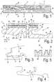
- FIG. 16represents coupling parts which can be applied with such fold-down floor panels
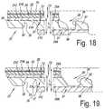
- FIGS. 17 to 19represent variants to FIG. 16 ;
- FIG. 20represents a method according to the invention.
- FIGS. 21 and 22represent variants.
- FIG. 1represents a floor panel 1 according to the invention.
- the represented floor panel 1comprises a decor 2 , which relates to printed wood decor.
- Thisrelates to an oblong rectangular floor panel 1 , which as a result has a pair of long edges 3 - 4 and a pair of short edges 5 - 6 .
- Each pair of edgesis provided with coupling parts, which are indicated by the reference numbers 7 - 8 and 9 - 10 , respectively.
- the shape of the coupling parts 7 - 8is evident from FIG. 2 .
- Thisrelates to a tongue and groove connection comprising a tongue 11 and a groove 12 , the groove being bordered by an upper lip 13 and a lower lip 14 .
- the lower lip 14protrudes to beyond the upper lip 13 .
- the connectioncomprises locking elements 15 - 16 , in the form of a protrusion 15 on the lower side of the tongue 11 and an upward-directed locking element 16 in the portion of the lower lip 14 that protrudes beyond the upper lip 13 , which, by cooperating locking surfaces 17 - 18 , counteract the moving apart of the tongue 11 and the groove 12 in the horizontal direction H.
- the upper side 19 of the tongue 11cooperates with the lower side 20 of the upper lip 13 in order to counteract the separation in the vertical direction V.
- FIGS. 3 and 4show how the coupling parts 7 - 8 can be coupled by means of a turning movement ( FIG. 3 ) as well as a substantially horizontal snap movement ( FIG. 4 ).
- FIG. 2also shows the construction of the floor panel 1 . It is constructed of a substrate 21 , a decor carrier 22 with decor 2 , a wear layer 23 and a lacquer layer 24 .
- the substrate 21consists of two substrate layers 21 A and 21 B realized on the basis of PVC.
- the substrate layer 21 Ais rigid. For this purpose, no plasticizers are present in this layer 21 A, or plasticizers are present in an amount of less than 15 phr only. Examples of plasticizers which can be used have already been mentioned. Also, the substrate layer 21 A comprises a proportion of filler situated between 30 and 70 percent by weight. Preferably, chalk, talc and/or lime is used, possibly supplemented with wood, bamboo and/or cork particles. Further, the substrate layer 21 A can comprise an impact modifier, a stabilizer, such as a Ca/Zn stabilizer, and/or a color pigment, such as carbon black.
- the thickness T 1 of the substrate 21 Ais at least 2 mm. The result is that the substrate layer 21 A has a high bending stiffness. This is advantageous, considering that the risk of warping of the floor panel 1 and of forming pushed-up edges under incident sunlight already is counteracted to a certain extent.
- the glass fiber fleece 25is enclosed between the substrate layer 21 A and 21 B. In this manner, it can perform its function at its best. Possibly, the glass fiber fleece 25 is at least partially impregnated with thermoplastic material of the substrate layers 21 A and/or 21 B. This provides for a strong embedding in the substrate 21 , such that it can perform its function even better.
- the position of the glass fiber layer 25provides for that it extends uninterruptedly in both coupling parts 7 - 8 . This is positive for the effectivity thereof, certainly at the respective edges 3 - 4 of the panel 1 .
- the rigid substrate layer 21 Ais obtained by means of a strewing process.
- a very good connection with the glass fleece 25can be obtained.
- the glass fleece 25can also have a support function.
- the glass fleece 25can also form a separation between the strewn layer 21 A and the layer 21 B in case the latter also would be strewn. This is certainly useful prior to consolidating, as this prevents a mutual mixing of the strewn material among the layers.
- the substrate layer 21 Ais not foamed. In comparison with foamed layers, hereby a better resistance against telegraphy and indentation effects is offered.
- the density of the layer 21 Ais situated between 1300 and 2000 kg per cubic meter.
- the zone where the upper side 19 of the tongue and the lower side 20 of the upper lip cooperateis situated entirely in the rigid substrate layer 21 A, just like the zone where the locking elements 15 - 16 cooperate. This provides for that a strong mechanical coupling can be effected, wherein gap formation will arise less easily.
- the upper lip 13is partially realized from the layer 17 A, and the lower lip 14 even entirely. This provides for a reduced risk of breaking of one or both of the lips 13 - 14 . Certainly with the lower lip 14 , this is advantageous as this lip 14 may not break as a result of the possible bending it is subjected to during the coupling of the edges 3 - 4 . Otherwise, the coupling will be lost.
- the substrate layer 21 Bis more flexible than the layer 21 A. To this aim, in this layer 21 B more plasticizers are present, namely at least 15 phr.
- This flexible layer 21 Bprovides for that, regardless of the relatively stiff panel 1 , no ticking sound is created when this panel 1 is walked upon. Thus, due to the soft character, it has sound-absorbing properties. Moreover, such layer 21 B is easier to deform in order to create a deep relief in the upper side of the panel 1 .
- the proportion of filler in this layer 21 Bis situated between 30 and 70 percent by weight.
- the substrate layer 21 Bcan comprise an impact modifier, a stabilizer, such as a Ca/Zn stabilizer, and/or a color pigment, such as carbon black.
- the thickness T 2 of the substrate layer 21 Bis situated between 0.5 and 1 mm.
- the layers 17 A and 17 Bare connected to each other by means of thermal lamination. In this manner, a reduced risk of delamination is obtained in comparison with the use of glue or the like.
- the decor carrier 22 on which the decor is printedrelates to a PVC film or foil.
- the transparent wear layer 23relates to a PVC layer with a thickness situated between 250 and 750 micrometer.
- the overall thickness T of the floor panel 1is situated between 3.5 and 6 mm.
- FIG. 5better shows the lacquer 24 which is provided on the wear layer 23 .
- Thisrelates to a lacquer realized on the basis of urethane acrylate.
- the relief 26 provided in the upper side of the panel 1is visible, too.
- FIG. 6shows coupling parts 7 - 8 similar to those from FIG. 2 , however, the substrate 21 is constructed differently.
- the layer 21 Ais constructed similar to the layer 21 A of FIG. 2 , however, thinner.
- a second rigid substrate layer 21 Cis present in the substrate 21 as well, which also is made of PVC.
- the substrate layer 21 Ccontains no plasticizers, or plasticizers in an amount of less than 15 phr only.
- the substrate layer 21 Calso comprises a proportion of filler situated between 30 and 70 percent by weight.
- the substrate layer 21 Ccan comprise an impact modifier, a stabilizer, such as a Ca/Zn stabilizer, and/or a color pigment, such as carbon black.
- the overall thickness T 1 of the substrate layers 21 A and 21 Cis at least 2 mm.
- both substrate layers 21 A and 21 Cgives a high bending stiffness to the panel 1 , which even is increased by the enclosed glass fleece 25 .
- the position of the glass fleece 25is such that it extends uninterruptedly through both coupling parts 7 - 8 . And it is positioned at the height of the center line of the tongue 11 and goes through the most inwardly located point of the groove 12 . Thus, at those locations additional support is given, which is beneficial for the strength of the tongue 11 and groove 12 .
- the rigid layers 21 A and 21 Care formed by means of a strewing process which is known as such from WO 213/179261. It offers the advantage that the glass fleece 25 can be embedded very well into the rigid whole, with a particularly stable sandwich as a result.
- the rigid layer 21 Calso is not foamed.
- FIG. 7shows coupling parts 7 - 8 similar to those from FIG. 6 , however, the substrate 21 is constructed differently.
- the substrate layers 21 A and 21 Care constructed similar to the layers 21 A and 21 C of FIG. 6 .
- the substrate layer 21 Dcontains no plasticizers, or plasticizers in an amount of less than 15 phr only.
- the substrate layer 21 Dcomprise a proportion of filler situated between 30 and 70 percent by weight.
- the substrate layer 21 Dcan comprise an impact modifier, a stabilizer, such as a Ca/Zn stabilizer, and/or a color pigment, such as carbon black.
- the overall thickness T 1 of the substrate layers 21 A, 21 C and 21 Dis at least 2 mm.
- the resultis that the whole of the substrate layers 21 A, 21 C and 21 D gives a high bending stiffness to the panel 1 , which even is increased by the presence of two enclosed glass fleeces 25 A and 25 B.
- the two glass fleeces 25 A and 25 Bare located off the center of the panel 1 at a distance D from each other of at least 1 ⁇ 5 the thickness T of the panel 1 .
- the substrate layers 21 C and 21 Dare realized thinner than the center layer 21 A, however, have a thickness of at least 1 ⁇ 5 the thickness of the center layer 21 A.
- the resultis a particularly balanced and stable sandwich construction.
- the substrate layers 21 A, 21 C and/or 21 D as suchmay comprise a plurality of substrate layers and thus be multi-layered.
- the substrate layer 21 Amay comprise a plurality of substrate layers which may or may not have a mutually differing composition, such as a mutually differing proportion of filler or plasticizer. The same is applicable to the layers 21 C and 21 D and more generally to all substrate layers mentioned in this document.
- the two glass fleeces 25 A and 25 Bhave a weight smaller than 65 gram per square meter. This has a positive influence on the process speed and practically no detrimental influence on the dimensional stability, at least not in the application with rigid substrate layers.
- FIG. 8shows a variant of FIG. 7 , wherein the substrate 21 at the lower side comprises a sound-absorbing substrate layer 21 E of XPE foam.
- the thickness of this layer 21 Eis situated between 1 and 2 mm.
- FIG. 9shows a variant of FIG. 7 , wherein the glass fleeces 25 A- 25 B are positioned somewhat differently.
- the glass fleece 25 Agoes centrally through the zone where the upper side 19 of the tongue 11 cooperates with the lower side 20 of the upper lip 13 , whereas the glass fleece 25 goes centrally through the zone where the locking elements 15 - 16 cooperate. This provides for an excellent horizontal and vertical locking.
- FIG. 10shows a variant of FIG. 9 .
- the glass fleece 25 Ais positioned similarly, however, the glass fleece 25 B extends uninterruptedly in the coupling part 8 . It extends continuously through the lower lip 14 . This is beneficial for the strength of this lip 14 .
- FIG. 11shows a similar construction of the substrate 21 as in FIG. 10 , however, the coupling parts 7 - 8 have another configuration.
- the lower side of the tongue 11is convex, while the upper side of the lower lip 14 is concave.
- FIGS. 12 and 13show two more variants, where the lower side of the tongue 11 and the upper side of the lower lip 14 comprise a flat part.
- FIGS. 14 and 15represent how floor panels 1 can be coupled to each other by means of the fold-down technique.
- the short pair of edges 5 - 6 of the panel 1is provided with the coupling parts 9 - 10 shown in FIG. 16 .
- Thoseare realized in the form of a downward-directed hook 27 and an upward-directed hook 28 .
- the downward hook 27has a lip 29 with a downward-directed locking element 30
- the upward hook 28has a lip 31 with an upward-directed locking element 32 .
- the locking elements 30 and 32cooperate, via locking surfaces 33 - 34 , in order to counteract the moving apart of the hooks 27 - 28 in horizontal direction.
- the hooks 27 - 28are also provided with vertically active locking elements 35 - 36 .
- the vertically active locking element 35is made as a separate insert, which is provided in a recess 37 in the downward hook 27 . This recess is situated partially in the rigid layers 21 A and 21 C. it is also possible to provide the insert 35 in the upward hook 28 .
- the lip 29is formed partially from the rigid layers 21 A and 21 C.
- the lip 31is formed entirely from the rigid layers 21 A and 21 D.
- the zone where the locking elements 30 and 32 cooperateis situated entirely in the rigid layer 21 a . All these measures are advantageous for the strength of the locking.
- the zone where the insert 35 cooperates with the locking element 36is situated in the more flexible layer 21 B. However, it is not excluded that this last zone is situated at least partially or entirely in the rigid layers 21 A and/or 21 C.
- the glass fiber layer 25 Ais situated at the height of the recess 37 . This provides for additional stability there, where the floor panel, due to the recess 37 , is somewhat weaker.
- the glass fiber layer 25 Aextends continuously in the lip 31 of the upward-directed hook 28 .
- FIG. 17shows a variant of FIG. 16 .
- the insert 36is provided in a recess 37 in the upward hook 28 .
- the zone where the insert 36 cooperates with the locking element 35indeed is situated in a rigid substrate layer, namely in the rigid layer 21 A. This provides for a very good vertical locking.
- FIG. 18shows a variant of FIGS. 16 and 17 , wherein the vertically active locking elements are realized from the material of the panel 1 .
- the vertically active locking elementsare realized from the material of the panel 1 .
- the locking elements 35 - 36are present, namely the locking elements 35 - 36 as well as the locking surfaces 33 - 34 , which provide for the horizontal as well as the vertical locking.
- All the vertical locking elementsare made from the rigid layers 21 A and 21 C.
- the glass fleeceis situated at the height of the zone where the locking elements 35 - 36 cooperate.
- the glass fleece 25 Bextends continuously through the lip 31 .
- FIG. 19shows a variant of FIG. 18 , wherein the vertically active locking elements 35 - 36 are situated at the end of the lip 31 .
- the glass fleece 25 Bgoes therethrough.
- FIG. 20represents a method according to the fifth aspect of the invention. This method can be used in order to obtain the substrate construction of the panels 1 of, for example, FIG. 7 .
- This methodcan be used in order to obtain the substrate construction of the panels 1 of, for example, FIG. 7 .
- the rigid substrate layers 21 D, 21 A and 21 Care provided.
- the rigid thermoplastic material thereofis strewn onto a transport belt 39 by means of strewing devices 38 .
- On the strewn layers 21 D and 21 Aa glass fleece 25 B and a glass fleece 25 A, respectively, is provided.
- the glass fleeces 25 A and 25 Bare unrolled from rollers 40 and provided on the respective substrate layers 21 D and 21 A.
- the formed complexsubsequently is transported to a double-belt press 41 , in which it is consolidated under the influence of pressure and/or heat.
- the press device 41comprises, in transport direction, heating elements 42 , an S-roller 43 and cooling elements 44 .
- the heating elements 42heat the complex brought into the press device 41 , as a result of which the individual layers can be connected to each other more easily and better.
- the use of the S-roller 43is advantageous as it provides for a calibration of the respective layers.
- the cooling elements 44finally cool the consolidated complex, such that it can be processed more rapidly.
- the more flexible substrate layer 21 Bis provided on the consolidated whole, by means of a calendering device 45 which consists of more than one calendering roller 46 .
- FIG. 21shows a variant of FIG. 20 .
- the glass fleece 25is brought into contact with a press element in the press device 43 . This is different to FIG. 20 , where each glass fleece is enclosed between rigid substrate layers.
- FIG. 22shows another alternative manner of providing a glass fleece 25 on a rigid substrate layer.
- Reference number 47indicates an extrusion device with which the rigid substrate layer 21 A is manufactured. This substrate layer 21 subsequently is transported between guide rollers 48 .
- the glass fleece 25is wound off a roll 49 and provided, between two of such guide rollers, on the substrate layer 21 A. It is clear that this whole can be processed further and possibly can be supplemented with subsequent substrate layers and/or glass fleeces. It is also noted that this technique and be applied in an advantageous manner with any type of substrate layer of thermoplastic material, independently of whether this relates to a rigid, semi-rigid or flexible substrate layer.
- the rigid substrate layer ( 21 A)comprises plasticizers in an amount of less than 15 phr, less than 10 phr or less than 5 phr, or does not comprise any plasticizers.
- thermoplastic material of the rigid substrate layer ( 21 A)comprises PVC.
- thermoplastic material of the rigid substrate layer ( 21 A)comprises a proportion of filler, which proportion preferably is situated between 30 and 70 percent by weight or between 45 and 65 percent by weight.
- the proportion of fillercomprises an inorganic filler, such as chalk, lime and/or talc, and/or an organic filler, such as wood, bamboo and/or cork.
- the substratecomprises a second rigid substrate layer ( 21 C) of thermoplastic material, which preferably is not foamed.
- the substratebetween the decor and the rigid substrate layer ( 21 A), comprises a substrate layer ( 21 B) of thermoplastic material which is more flexible or more compressible than the rigid substrate layer ( 21 A).
- the floor panel ( 1 )comprises a wear and/or lacquer layer ( 23 and/or 24 ) provided above the decor ( 2 ).
- the coupling parts ( 7 - 8 , 9 - 10 )are realized as a tongue and groove connection, the groove ( 12 ) being bordered by an upper ( 13 ) and a lower lip ( 14 ), and wherein this connection comprises locking elements ( 15 - 16 ).
- Method 38Method according to any of the paragraphs 35 to 37, wherein the method also comprises providing the decor ( 2 ) and a possible wear and/or lacquer layer ( 23 and/or 24 ).
Landscapes
- Engineering & Computer Science (AREA)
- Architecture (AREA)
- Civil Engineering (AREA)
- Structural Engineering (AREA)
- Mechanical Engineering (AREA)
- Composite Materials (AREA)
- Chemical & Material Sciences (AREA)
- Textile Engineering (AREA)
- Ceramic Engineering (AREA)
- Life Sciences & Earth Sciences (AREA)
- Wood Science & Technology (AREA)
- Floor Finish (AREA)
- Laminated Bodies (AREA)
Abstract
Description
- an inorganic filler, such as chalk, lime and/or talc;
- an organic filler, such as wood, bamboo and/or cork; and/or
- a mineral filler.
- the floor panel bends under the own weight thereof less than 10 cm per meter and still better less than 5 cm per meter; and/or
- the floor panel shows a modulus of elasticity or Young's modulus of at least 2000 N per square millimeter, at least 3000 N per square millimeter or at last 3500 N per square millimeter.
- the upper lip is at least partially realized from the first or the possible second rigid substrate layer;
- the lower lip is at least partially realized from the first or the possible third rigid substrate layer;
- the center line through the tongue is situated in the first rigid substrate layer;
- the most inwardly located point of the groove is situated in the first rigid substrate layer;
- the zone where the upper side of the tongue cooperates with the lower side of the upper lip is situated at least partially or entirely in the first or the possible second rigid substrate layer;
- the zone where the possible locking elements cooperate is situated at least partially or entirely in the first or the possible third rigid substrate layer;
- the glass fiber layer is situated at the height of the zone where the upper side of the tongue cooperates with the lower side of the upper lip;
- the glass fiber layer is situated at the height of the zone where the possible locking elements cooperate;
- the glass fiber layer is situated on the center line through the tongue;
- the glass fiber layer is situated at the height of the most inwardly located point of the groove;
- in the case that the zone where the upper side of the tongue cooperates with the lower side of the upper lip is situated at another location than the zone where the possible locking elements cooperate, preferably at least two glass fiber layers are present, wherein it is preferably valid that the one glass fiber layer is situated at the height of the zone where the upper side of the tongue cooperates with the lower side of the upper lip, and the other is situated at the height of the zone where the possible locking elements cooperate;
- the glass fiber layer extends uninterruptedly or continuously through the lower lip or the upper lip; and/or
- the glass fiber layer extends uninterruptedly or continuously in at least one of the coupling parts.
- the type wherein the coupling parts are configured such that they allow coupling two of such floor panels at the respective edges by means of a turning movement, wherein the floor panel with the tongue, from an inclined position in which the tongue already is partially situated in the groove, is turned downward in order to bring the tongue completely into the groove and couple the respective edges to each other;
- the type wherein the coupling parts are configured such that they allow coupling two of such floor panels at the respective edges by means of a substantially linear movement in the plane of the floor panels and substantially perpendicular to the respective edges, preferably with the performance of a snap action;
- the type wherein the coupling parts are configured such that they allow coupling two of such floor panels at the respective edges both by means of a turning movement as described herein above and by means of a substantially linear movement in the plane of the floor panels and substantially perpendicular to the respective edges, preferably with the performance of a snap action.
- the lip of the downward-directed hook-shaped part is at least partially realized from the first or the possible second rigid substrate layer;
- the lip of the upward-directed hook-shaped part is at least partially realized from the first or the possible third rigid substrate layer;
- the zone where the upward-directed locking element cooperates with the downward-directed locking element in order to effect the horizontal locking, is situated at least partially or entirely in the first or the possible third rigid substrate layer;
- the zone or zones where the possible vertically active locking elements cooperate, are situated at least partially or entirely in the first, the possible second or the possible third rigid substrate layer;
- the glass fiber layer is situated at the height of the zone where the upward-directed locking element cooperates with the downward-directed locking element in order to effect the horizontal locking;
- the glass fiber layer is situated at the height of the zone or zones where the possible vertical locking elements cooperate;
- in the case that the zone, where the upward-directed locking element cooperates with the downward-directed locking element in order to effect the horizontal locking, is situated at another location than a zone where the possible vertically active locking elements cooperate, preferably at least two glass fiber layers are present, wherein it is preferably valid that the one glass fiber layer is situated at the height of the zone where the upward-directed locking element cooperates with the downward-directed locking element in order to effect the horizontal locking, and the other is situated at the height of the zone where the possible vertically active locking elements cooperate;
- the glass fiber layer extends uninterruptedly or continuously in the lip of the downward-directed hook-shaped part or in the lip of the upward-directed hook-shaped part; and/or
- the glass fiber layer extends uninterruptedly or continuously in at least one of the hook-shaped parts.
- providing a first rigid substrate layer of thermoplastic material by means of a first strewing treatment;
- providing a glass fiber layer on the strewn substrate layer;
- providing a second rigid substrate layer of thermoplastic material on the glass fiber layer, by means of a second strewing treatment;
- consolidating the strewn substrate layers and the glass fiber layer under the influence of pressure and/or heat;
- providing, on the consolidated second substrate layer, a more flexible or more compressible substrate layer of thermoplastic material by applying this thermoplastic material in liquid condition.
- the upper lip (13) is at least partially realized from the first (21A) and/or the possible second rigid substrate layer (21C);
- the lower lip (14) is at least partially or entirely realized from the first (21A) or the possible third rigid substrate layer (21D);
- the center line through the tongue (11) is situated in the first rigid substrate layer (21A);
- the most inwardly located point of the groove (12) is situated in the first rigid substrate layer (21A);
- the zone where the upper side of the tongue (11) cooperates with the lower side of the upper lip (13) is situated at least partially or entirely in the first (21A) or the possible second rigid substrate layer (21C);
- the zone where the locking elements (15-16) cooperate is situated at least partially or entirely in the first (21A) and/or the possible third rigid substrate layer (21D);
- the glass fiber layer (25) is situated at the height of the zone where the upper side of the tongue (11) cooperates with the lower side of the upper lip (13);
- the glass fiber layer (25) is situated at the height of the zone where the locking elements (15-16) cooperate;
- the glass fiber layer (25) is situated on the center line through the tongue (11);
- the glass fiber layer (25) is situated at the height of the most inwardly located point of the groove (12);
- in the case that the zone where the upper side of the tongue (11) cooperates with the lower side of the upper lip (13) is situated at another location than the zone where the locking elements (15-16) cooperate, preferably at least two glass fiber layers (25A-25B) are present, wherein it is preferably valid that the one glass fiber layer (25A) is situated at the height of the zone where the upper side of the tongue (11) cooperates with the lower side of the upper lip (13), and the other is situated at the height of the zone where the locking elements (15-16) cooperate;
- the glass fiber layer extends uninterruptedly or continuously in the lower lip or in the upper lip; and/or
- the glass fiber layer (25) extends uninterruptedly or continuously in at least one of the coupling parts (7-8,9-10).
- providing a first rigid substrate layer (21A) of thermoplastic material by means of a first strewing treatment;
- providing a glass fiber layer (25) on the strewn substrate layer (21A);
- providing a second rigid substrate layer (21C) of thermoplastic material on the glass fiber layer (25), by means of a second strewing treatment;
- consolidating the strewn substrate layers (21A-21C) and the glass fiber layer (25) under the influence of pressure and/or heat;
- providing, on the consolidated second substrate layer (21C), a more flexible or more compressible substrate layer (21B) of thermoplastic material by applying this thermoplastic material in liquid condition.
Claims (19)
Priority Applications (1)
| Application Number | Priority Date | Filing Date | Title |
|---|---|---|---|
| US16/345,855US10988939B2 (en) | 2016-11-10 | 2017-11-03 | Floor panel and method for manufacturing a floor panel |
Applications Claiming Priority (5)
| Application Number | Priority Date | Filing Date | Title |
|---|---|---|---|
| US201662420094P | 2016-11-10 | 2016-11-10 | |
| BE2016/5868 | 2016-11-22 | ||
| BE20165868ABE1024723B1 (en) | 2016-11-10 | 2016-11-22 | Floor panel and method for manufacturing a floor panel. |
| US16/345,855US10988939B2 (en) | 2016-11-10 | 2017-11-03 | Floor panel and method for manufacturing a floor panel |
| PCT/IB2017/056855WO2018087637A1 (en) | 2016-11-10 | 2017-11-03 | Floor panel and method for manufacturing a floor panel |
Related Parent Applications (1)
| Application Number | Title | Priority Date | Filing Date |
|---|---|---|---|
| PCT/IB2017/056855A-371-Of-InternationalWO2018087637A1 (en) | 2016-11-10 | 2017-11-03 | Floor panel and method for manufacturing a floor panel |
Related Child Applications (1)
| Application Number | Title | Priority Date | Filing Date |
|---|---|---|---|
| US17/205,475ContinuationUS11993939B2 (en) | 2016-11-10 | 2021-03-18 | Floor panel |
Publications (2)
| Publication Number | Publication Date |
|---|---|
| US20190292793A1 US20190292793A1 (en) | 2019-09-26 |
| US10988939B2true US10988939B2 (en) | 2021-04-27 |
Family
ID=57442403
Family Applications (17)
| Application Number | Title | Priority Date | Filing Date |
|---|---|---|---|
| US16/345,855ActiveUS10988939B2 (en) | 2016-11-10 | 2017-11-03 | Floor panel and method for manufacturing a floor panel |
| US16/345,865ActiveUS11091919B2 (en) | 2016-11-10 | 2017-11-03 | Floor panel and method for manufacturing a floor panel |
| US17/205,475ActiveUS11993939B2 (en) | 2016-11-10 | 2021-03-18 | Floor panel |
| US17/361,895Active2037-11-13US11668105B2 (en) | 2016-11-10 | 2021-06-29 | Floor panel and method for manufacturing a floor panel |
| US17/701,434ActiveUS12116785B2 (en) | 2016-11-10 | 2022-03-22 | Floor panel |
| US17/701,440ActiveUS12116786B2 (en) | 2016-11-10 | 2022-03-22 | Floor panel |
| US17/701,432ActiveUS12006702B2 (en) | 2016-11-10 | 2022-03-22 | Floor panel |
| US18/300,600Active2038-02-16US12410619B2 (en) | 2016-11-10 | 2023-04-14 | Floor panel |
| US18/673,759PendingUS20240309652A1 (en) | 2016-11-10 | 2024-05-24 | Floor panel |
| US18/830,756PendingUS20250003233A1 (en) | 2016-11-10 | 2024-09-11 | Floor panel and method for manufacturing a floor panel |
| US18/830,746PendingUS20250003232A1 (en) | 2016-11-10 | 2024-09-11 | Floor panel |
| US18/830,741PendingUS20250003230A1 (en) | 2016-11-10 | 2024-09-11 | Floor panel |
| US18/830,751PendingUS20240426113A1 (en) | 2016-11-10 | 2024-09-11 | Floor panel and method for manufacturing a floor panel |
| US18/830,727PendingUS20250003228A1 (en) | 2016-11-10 | 2024-09-11 | Floor panel |
| US18/830,734PendingUS20250003229A1 (en) | 2016-11-10 | 2024-09-11 | Floor panel |
| US18/830,723PendingUS20250003227A1 (en) | 2016-11-10 | 2024-09-11 | Floor panel |
| US18/830,744PendingUS20250003231A1 (en) | 2016-11-10 | 2024-09-11 | Floor panel |
Family Applications After (16)
| Application Number | Title | Priority Date | Filing Date |
|---|---|---|---|
| US16/345,865ActiveUS11091919B2 (en) | 2016-11-10 | 2017-11-03 | Floor panel and method for manufacturing a floor panel |
| US17/205,475ActiveUS11993939B2 (en) | 2016-11-10 | 2021-03-18 | Floor panel |
| US17/361,895Active2037-11-13US11668105B2 (en) | 2016-11-10 | 2021-06-29 | Floor panel and method for manufacturing a floor panel |
| US17/701,434ActiveUS12116785B2 (en) | 2016-11-10 | 2022-03-22 | Floor panel |
| US17/701,440ActiveUS12116786B2 (en) | 2016-11-10 | 2022-03-22 | Floor panel |
| US17/701,432ActiveUS12006702B2 (en) | 2016-11-10 | 2022-03-22 | Floor panel |
| US18/300,600Active2038-02-16US12410619B2 (en) | 2016-11-10 | 2023-04-14 | Floor panel |
| US18/673,759PendingUS20240309652A1 (en) | 2016-11-10 | 2024-05-24 | Floor panel |
| US18/830,756PendingUS20250003233A1 (en) | 2016-11-10 | 2024-09-11 | Floor panel and method for manufacturing a floor panel |
| US18/830,746PendingUS20250003232A1 (en) | 2016-11-10 | 2024-09-11 | Floor panel |
| US18/830,741PendingUS20250003230A1 (en) | 2016-11-10 | 2024-09-11 | Floor panel |
| US18/830,751PendingUS20240426113A1 (en) | 2016-11-10 | 2024-09-11 | Floor panel and method for manufacturing a floor panel |
| US18/830,727PendingUS20250003228A1 (en) | 2016-11-10 | 2024-09-11 | Floor panel |
| US18/830,734PendingUS20250003229A1 (en) | 2016-11-10 | 2024-09-11 | Floor panel |
| US18/830,723PendingUS20250003227A1 (en) | 2016-11-10 | 2024-09-11 | Floor panel |
| US18/830,744PendingUS20250003231A1 (en) | 2016-11-10 | 2024-09-11 | Floor panel |
Country Status (10)
| Country | Link |
|---|---|
| US (17) | US10988939B2 (en) |
| EP (7) | EP4458565A3 (en) |
| KR (5) | KR102478410B1 (en) |
| CN (5) | CN110036161A (en) |
| BE (2) | BE1024723B1 (en) |
| BR (1) | BR112019009389B1 (en) |
| CA (2) | CA3040811A1 (en) |
| CO (2) | CO2019007200A2 (en) |
| EA (3) | EA201991148A1 (en) |
| WO (2) | WO2018087638A1 (en) |
Cited By (8)
| Publication number | Priority date | Publication date | Assignee | Title |
|---|---|---|---|---|
| US20220136238A1 (en)* | 2019-02-26 | 2022-05-05 | Colin Christopher Felton | Interlocking Composite Construction Block |
| US11565501B2 (en)* | 2018-06-06 | 2023-01-31 | Flooring Industries Limited, Sarl | Floor panel and method for manufacturing a floor panel |
| US11975526B2 (en) | 2019-09-25 | 2024-05-07 | Unilin, Bv | On-line synchronous registering co-extrusion SPC floor and production process therefor |
| US11993939B2 (en) | 2016-11-10 | 2024-05-28 | Unilin, Bv | Floor panel |
| US12134900B2 (en) | 2019-02-04 | 2024-11-05 | Unilin Bv | Floor panel and method for manufacturing the same |
| US12203275B1 (en)* | 2023-12-28 | 2025-01-21 | I4F Licensing Nv | Floor board and method for manufacturing such floor boards |
| US12234655B2 (en) | 2014-07-04 | 2025-02-25 | Unilin Bv | Floor panel and method for manufacturing floor panels |
| US12442196B2 (en) | 2016-11-22 | 2025-10-14 | Unilin, Bv | Floor panel |
Families Citing this family (61)
| Publication number | Priority date | Publication date | Assignee | Title |
|---|---|---|---|---|
| PL4092213T3 (en) | 2010-01-11 | 2024-03-25 | Välinge Innovation AB | Floor covering with interlocking design |
| BE1020722A3 (en)* | 2012-06-01 | 2014-04-01 | Unilin Bvba | PANEL FOR FORMING A FLOOR COVERING AND METHOD FOR MANUFACTURING SUCH PANELS. |
| EP3943687B1 (en)* | 2015-01-16 | 2025-03-05 | Unilin, BV | Floor covering system |
| EP3526422B1 (en)* | 2016-10-17 | 2023-07-26 | Novalis Holdings Limited | A dimensionally stable floor panel |
| BE1024909B1 (en) | 2017-01-11 | 2018-08-16 | Ivc Bvba | Method for manufacturing a substrate for a floor panel |
| BE1025188B1 (en)* | 2017-04-24 | 2018-12-03 | Kreafin Group Sa | METHOD FOR FORMING A VOLTAGE-FREE MULTI-LAYER PVC PLATE MATERIAL |
| ES2902394T3 (en)* | 2017-05-15 | 2022-03-28 | Flooring Ind Ltd Sarl | A floor element for forming a floor covering and a floor covering |
| CN108442642A (en)* | 2018-04-12 | 2018-08-24 | 安徽森泰木塑集团股份有限公司 | A kind of outdoor flooring and its preparation process |
| US11752661B2 (en)* | 2018-05-21 | 2023-09-12 | 5R Technologies Sdn. Bhd. | Natural effect panel and method of fabricating the same |
| NL2020972B1 (en)* | 2018-05-23 | 2019-12-02 | Innovations4Flooring Holding N V | Multi-purpose tile system, tile covering, and tile |
| BE1026356B1 (en)* | 2018-06-06 | 2020-01-17 | Ivc Bvba | FLOOR PANELS |
| PT3581731T (en)* | 2018-06-15 | 2023-03-03 | Akzenta Paneele Profile Gmbh | Panel |
| EP3590709B1 (en) | 2018-07-02 | 2022-09-07 | Flooring Industries Limited, SARL | Methods to provide a pvc floor covering |
| MX2021004663A (en) | 2018-10-23 | 2021-05-28 | Carlisle Construction Mat Llc | Insulation board with improved performance. |
| NL2021887B1 (en) | 2018-10-26 | 2020-05-13 | I4F Licensing Nv | Multi-purpose tile system, tile covering, and tile |
| NL2022369B9 (en) | 2019-01-10 | 2020-09-17 | Champion Link Int Corp | Panel suitable for assembling a floor covering |
| KR102824603B1 (en) | 2019-03-05 | 2025-06-23 | 세라록 이노베이션 에이비 | Method for forming a home in a board element and associated panels |
| US11377855B2 (en) | 2019-03-25 | 2022-07-05 | Ceraloc Innovation Ab | Mineral-based panel comprising grooves and a method for forming grooves |
| CN113874206A (en)* | 2019-05-20 | 2021-12-31 | 肖氏工业集团公司 | Cellulose-based composite board |
| CN110626027B (en) | 2019-08-16 | 2021-03-16 | 浙江永裕家居股份有限公司 | Co-extrusion SPC foamed floor and preparation method thereof |
| US20220403670A1 (en) | 2019-10-10 | 2022-12-22 | Flooring Industries Limited, Sarl | Floor covering and set of components for such a floor covering |
| WO2021094625A1 (en)* | 2019-11-15 | 2021-05-20 | Beaulieu International Group Nv | Multilayer floor panel based on a pvc plastisol |
| EP4100249A1 (en) | 2019-12-10 | 2022-12-14 | Flooring Industries Limited, SARL | Floor element |
| BE1027841B1 (en) | 2019-12-10 | 2021-07-08 | Unilin Bv | FLOOR ELEMENT |
| BE1027843B1 (en)* | 2019-12-10 | 2021-07-08 | Ivc Bv | Floor element |
| EP3835027A1 (en)* | 2019-12-11 | 2021-06-16 | Akzenta Paneele + Profile GmbH | Method and apparatus for producing a decorated wall or floor panel |
| BE1027894B1 (en)* | 2019-12-19 | 2021-07-28 | Ivc Bv | FLOOR ELEMENT |
| CN114829126B (en) | 2019-12-27 | 2024-10-29 | 塞拉洛克创新股份有限公司 | Thermoplastic-based building panel comprising a balancing layer |
| CN111572161B (en)* | 2019-12-30 | 2022-06-03 | 绿城装饰工程集团有限公司 | Angle-foldable PVC rigid-flexible composite board and preparation method thereof |
| US11927020B2 (en) | 2020-01-31 | 2024-03-12 | Champion Link International Corporation | Floor panel and method of manufacturing a floor panel |
| US11391049B2 (en)* | 2020-01-31 | 2022-07-19 | Champion Link International Corporation | Panel and method of producing such a panel |
| US11718565B2 (en) | 2020-01-31 | 2023-08-08 | Champion Link International Corporation | Panel for forming a floor covering and such floor covering |
| NL2025684B1 (en) | 2020-05-26 | 2021-12-14 | Champion Link Int Corp | Panel and method for producing a panel |
| US11724537B2 (en) | 2020-05-26 | 2023-08-15 | Champion Link International Corporation | Panel and method for producing a panel |
| BE1028395B1 (en)* | 2020-06-12 | 2022-01-17 | Flooring Ind Ltd Sarl | Decorative panel with antimicrobial properties |
| BE1028427B1 (en)* | 2020-06-24 | 2022-02-01 | Flooring Ind Ltd Sarl | Floor panels and method for manufacturing floor panels and cutting tools used herein |
| US11326356B2 (en) | 2020-07-15 | 2022-05-10 | Champion Link International Corporation | Floor or wall panel |
| US11530536B2 (en) | 2020-07-15 | 2022-12-20 | Champion Link International Corporation | Panel |
| US20230287690A1 (en)* | 2020-07-17 | 2023-09-14 | Flooring Industries Limited, Sarl | Coated panel |
| BE1028493B1 (en)* | 2020-07-17 | 2022-02-15 | Unilin | Clad panel, method for its manufacture and milling tool used |
| EP4232655A4 (en)* | 2020-10-23 | 2024-10-16 | Välinge Innovation AB | BUILDING PLATE WITH FIRST AND SECOND LOCKING SYSTEM |
| US12180702B2 (en)* | 2020-11-04 | 2024-12-31 | ROM Development Corp. | Fire-resistant composite structural building panels |
| PL4001546T3 (en)* | 2020-11-18 | 2024-12-16 | Unilin, Bv | FLOOR PANEL |
| WO2022139664A1 (en)* | 2020-12-21 | 2022-06-30 | Ceraloc Innovation Ab | Underlay element for flooring and floor assembly |
| CN113322683B (en)* | 2021-04-25 | 2022-11-22 | 佛山市高明尚昂科技有限公司 | Hard composite artificial leather capable of being embossed and preparation method thereof |
| EP4086408B1 (en)* | 2021-05-05 | 2024-10-16 | Bart Oerlemans BV | Panel |
| BE1030080B1 (en) | 2021-12-23 | 2023-07-24 | Flooring Ind Ltd Sarl | Panel |
| BE1030234B1 (en)* | 2022-01-31 | 2023-08-29 | Kreafin Group Sa | METHOD FOR FORMING A MULTI-LAYER PVC SHEET MATERIAL WITH A FOAMED BACKING |
| LU501429B1 (en) | 2022-02-09 | 2023-08-09 | Tarkett Gdl Sa | Hybrid acoustic floor panel |
| CN114770975B (en)* | 2022-04-20 | 2023-04-11 | 航天特种材料及工艺技术研究所 | Bionic composite material airfoil and manufacturing method thereof |
| EP4519521A1 (en) | 2022-05-05 | 2025-03-12 | Unilin, BV | Panel and method for manufacturing a panel |
| EP4565758A1 (en) | 2022-08-05 | 2025-06-11 | Unilin, BV | Decorative panel and method for manufacturing decorative panels |
| KR20250067139A (en)* | 2022-09-07 | 2025-05-14 | 뵈린게 이노베이션 에이비이 | Slopes on building panels and methods for manufacturing such building panels |
| EP4360874A1 (en) | 2022-10-25 | 2024-05-01 | Unilin, BV | Decorative panel and method for manufacturing such panel |
| WO2024089516A1 (en) | 2022-10-25 | 2024-05-02 | Unilin, Bv | Decorative panel and method for manufacturing such panel. |
| WO2024127269A1 (en) | 2022-12-14 | 2024-06-20 | Unilin, Bv | Decorative panel and method for manufacturing such panel |
| WO2024127294A1 (en) | 2022-12-16 | 2024-06-20 | Unilin, Bv | Method for manufacturing panels; and panels obtained by this method |
| EP4431274A1 (en)* | 2023-03-14 | 2024-09-18 | Unilin, BV | Decorative panel and method for manufacturing decorative panels |
| US20250263935A1 (en)* | 2023-03-27 | 2025-08-21 | Shaw Industries Group, Inc. | Decorative Article with Multilayered Porosity Base |
| WO2025111062A1 (en)* | 2023-11-22 | 2025-05-30 | Shaw Industries Group, Inc. | Decorative article with multilayered porosity base |
| WO2025151059A1 (en)* | 2024-01-10 | 2025-07-17 | Välinge Innovation AB | A method to produce a board element and a panel |
Citations (60)
| Publication number | Priority date | Publication date | Assignee | Title |
|---|---|---|---|---|
| US2944622A (en)* | 1957-01-28 | 1960-07-12 | Fenestra Inc | Sound absorbing structure |
| US3230375A (en)* | 1961-12-04 | 1966-01-18 | Mark B Van Wagoner | Laminated radiation resistant panels |
| US3360422A (en)* | 1965-10-19 | 1967-12-26 | Armstrong Cork Co | Reinforced cellular floor covering |
| US3712846A (en)* | 1971-06-23 | 1973-01-23 | Carpenter L & Co | Acoustical panel |
| US4018957A (en)* | 1975-04-01 | 1977-04-19 | Gaf Corporation | Coated fabric sheet-type material having resilient backing and process for making same |
| US4068030A (en)* | 1972-07-18 | 1978-01-10 | Armstrong Cork Company | Multilevel embossing by printing with a reactive monomer |
| US4710415A (en)* | 1986-09-11 | 1987-12-01 | Compo Industries, Inc. | Reinforced foam anti-fatigue floor tile module and method of making same |
| US5271200A (en)* | 1990-11-05 | 1993-12-21 | Permagrain Products, Inc. | Title display system |
| US5830549A (en)* | 1995-11-03 | 1998-11-03 | Triangle Pacific Corporation | Glue-down prefinished flooring product |
| US5925211A (en)* | 1997-04-21 | 1999-07-20 | International Paper Company | Low pressure melamine/veneer panel and method of making the same |
| US6271156B1 (en)* | 1998-09-22 | 2001-08-07 | Lydall, Inc. | Fire-resistant core for a combustible fire-rated panel |
| US6324809B1 (en)* | 1997-11-25 | 2001-12-04 | Premark Rwp Holdings, Inc. | Article with interlocking edges and covering product prepared therefrom |
| US6440538B1 (en)* | 2000-04-03 | 2002-08-27 | Lg Chem Ltd. | Abrasion resistant laminate |
| US6715239B2 (en)* | 2001-02-09 | 2004-04-06 | Precetti S.P.A. | Appropriate fitting-out structures for moist rooms and their installation procedure |
| WO2006043893A1 (en) | 2004-10-22 | 2006-04-27 | Välinge Innovation AB | Mechanical locking of floor panels with a flexible tongue |
| US20060099405A1 (en)* | 2004-11-08 | 2006-05-11 | Cerainteed Corporation | Polymer-fiber composite building material with bulk and aesthetically functional fillers |
| DE102005021662A1 (en) | 2005-05-06 | 2006-11-16 | Johannes Schulte | Floor tile has insulating layer located between backing plate and wear layer and formed by heavy foil |
| WO2008068245A1 (en) | 2006-12-06 | 2008-06-12 | Akzenta Paneele + Profile Gmbh | Panel and floor covering |
| US7386963B2 (en)* | 1998-06-03 | 2008-06-17 | Valinge Innovation Ab | Locking system and flooring board |
| US7449231B2 (en)* | 2004-09-21 | 2008-11-11 | Lg Chem, Ltd. | Wood flooring laminated with high pressure veneer and impregnated low weight printing paper |
| WO2009066153A2 (en) | 2007-11-23 | 2009-05-28 | Flooring Industries Limited, Sarl | Floor panel |
| US20090183457A1 (en)* | 2005-01-13 | 2009-07-23 | Berry Finance Nv | Floor panel |
| US7596920B2 (en)* | 2002-12-31 | 2009-10-06 | Barlinek, S.A. | Floor panel |
| US7802415B2 (en)* | 2001-07-27 | 2010-09-28 | Valinge Innovation Ab | Floor panel with sealing means |
| US20100326011A1 (en)* | 2007-07-25 | 2010-12-30 | Perennial Brazilcomercio De Madeiras Ltda | Multi-ply platforms and panels using such a platform |
| WO2012001109A1 (en)* | 2010-06-30 | 2012-01-05 | Spanolux N.V.- Div. Balterio | A panel comprising a polymeric composite layer and a method of manufacturing such panel |
| WO2012004701A2 (en)* | 2010-07-09 | 2012-01-12 | Flooring Industries Limited, Sarl | Floor panel |
| EP2447064A1 (en) | 2010-10-26 | 2012-05-02 | Rodolfo Comerio S.r.l. | Method and apparatus for registered embossing of a laminate |
| US8245477B2 (en)* | 2002-04-08 | 2012-08-21 | Välinge Innovation AB | Floorboards for floorings |
| WO2013026559A2 (en) | 2011-08-20 | 2013-02-28 | Ulrich Windmöller Consulting GmbH | Floor panel |
| US8495849B2 (en)* | 2004-01-13 | 2013-07-30 | Valinge Innovation Ab | Floor covering and locking systems |
| US8495851B2 (en)* | 2004-09-10 | 2013-07-30 | Serious Energy, Inc. | Acoustical sound proofing material and methods for manufacturing same |
| EP2636524A1 (en) | 2012-03-05 | 2013-09-11 | Rodolfo Comerio S.r.l. | Process and apparatus for registered embossing of extensible printed film or of a laminate comprising an extensible printed film |
| US8549807B2 (en)* | 2010-05-10 | 2013-10-08 | Flooring Industries Limited, Sarl | Floor panel and methods for manufacturing floor panels |
| CN103403280A (en) | 2011-03-03 | 2013-11-20 | 托维尔伊普克有限公司 | Floorboards with cork backing |
| WO2013179261A1 (en) | 2012-06-01 | 2013-12-05 | Unilin, Bvba | Panel for forming a floor covering and method for manufacturing such panels. |
| WO2014006593A1 (en) | 2012-07-06 | 2014-01-09 | Anest Iwata Europe S.R.L. | Paint-spray gun |
| US8640824B2 (en)* | 2012-05-10 | 2014-02-04 | Michael Freedman & Associates, Inc. | Acoustical vinyl flooring and methods of manufacture |
| US8689513B2 (en)* | 2011-10-28 | 2014-04-08 | Ulrich Windmöller Consulting GmbH | Floor covering |
| WO2015170274A1 (en) | 2014-05-07 | 2015-11-12 | Berryalloc Nv | Panel and method for manufacturing panels |
| US9217251B2 (en)* | 2010-06-15 | 2015-12-22 | Joseph D. D'Agostino | Articles and methods for laying ceramic tile floor |
| WO2016001859A1 (en) | 2014-07-04 | 2016-01-07 | Unilin, Bvba | Floor panel and method for manufacturing floor panels |
| WO2016016864A1 (en) | 2014-07-31 | 2016-02-04 | Unilin, Bvba | Method and installation for manufacturing a floor covering product and floor covering product obtained hereby |
| WO2016079225A1 (en) | 2014-11-20 | 2016-05-26 | Ivc N.V. | A method for manufacturing a panel including a reinforcement sheet, and a floor panel |
| KR101626470B1 (en) | 2015-09-16 | 2016-06-01 | (주)계림건축사사무소 | Non-foam type materials for reducing noise and floor system comprising the same |
| WO2016113377A1 (en) | 2015-01-16 | 2016-07-21 | Beaulieu International Group Nv | Covering panel and process of producing covering panels |
| US9399308B2 (en)* | 2006-03-27 | 2016-07-26 | Tarkett Ab | Method of making a floorboard |
| CN105908946A (en) | 2016-06-01 | 2016-08-31 | 惠州伟康新型建材有限公司 | Co-extruded composite stone-plastic polyvinyl chloride (PVC) floor |
| US9593493B2 (en)* | 2014-05-20 | 2017-03-14 | Euro Trade Flooring, S.L. | Multilayer lining plate for horizontal support surfaces and method of manufacturing same |
| US9598866B2 (en)* | 2012-04-02 | 2017-03-21 | Kronoplus Technical Ag | PVC-plastic panel |
| BE1023446A1 (en) | 2015-09-14 | 2017-03-22 | Ivc N V | Method for manufacturing floor panels and floor panel for forming a floor covering |
| US9611659B2 (en)* | 2014-06-20 | 2017-04-04 | Champion Link International Corporation | Panel suitable for assembling a waterproof floor or wall covering, method of producing a panel |
| US9695600B2 (en)* | 2011-10-03 | 2017-07-04 | Unilin Bvba | Panel and method for manufacturing panels |
| US9744753B2 (en)* | 2014-02-12 | 2017-08-29 | Wabash National, L.P. | Composite wood flooring and method of making the same |
| US9833974B2 (en)* | 2009-09-23 | 2017-12-05 | Lg Hausys, Ltd | Flooring material and fabrication method thereof |
| BE1024617A1 (en) | 2016-10-03 | 2018-04-26 | Ivc Bvba | Floor panel and method for manufacturing a floor panel. |
| US10094124B2 (en)* | 2016-05-04 | 2018-10-09 | Wellmade Floor Covering Int'l Inc. | Engineered plank material having waterproofed veneer and its manufacturing method |
| US10189236B2 (en)* | 2015-03-27 | 2019-01-29 | Golconda Holdings, Llc | System, method, and apparatus for magnetic surface coverings |
| US10343381B2 (en)* | 2016-06-28 | 2019-07-09 | John B. Troendle | Method of producing a glueless dustless composite flooring material system |
| US10544595B2 (en)* | 2016-08-26 | 2020-01-28 | Quickstyle Industries Inc. | Tile with protected imitation grout line |
Family Cites Families (224)
| Publication number | Priority date | Publication date | Assignee | Title |
|---|---|---|---|---|
| US360422A (en) | 1887-04-05 | Beer-pumping or air-pressure apparatus | ||
| US213740A (en) | 1879-04-01 | Improvement in wooden roofs | ||
| US1615096A (en) | 1925-09-21 | 1927-01-18 | Joseph J R Meyers | Floor and ceiling construction |
| US1778069A (en) | 1928-03-07 | 1930-10-14 | Bruce E L Co | Wood-block flooring |
| US1943663A (en) | 1929-10-30 | 1934-01-16 | United States Gypsum Co | Tile board and method of manufacturing same |
| US2111113A (en) | 1931-01-20 | 1938-03-15 | Albert C Fischer | Sponged sheet material |
| US2269926A (en) | 1939-01-06 | 1942-01-13 | Kenneth E Crooks | Composite board flooring |
| US2694025A (en) | 1951-06-27 | 1954-11-09 | Owens Corning Fiberglass Corp | Structural panel |
| US2811906A (en) | 1955-02-21 | 1957-11-05 | Clifford P Chappell | Method of forming a floor or surface covering |
| US3215225A (en) | 1961-11-29 | 1965-11-02 | Korfund Dynamics Corp | Laminated acoustic panels with outer metal layers, fibrous core and viscoelastic damping layer |
| US3139371A (en)* | 1963-05-24 | 1964-06-30 | John M Sisko | Core block construction |
| US3284980A (en) | 1964-07-15 | 1966-11-15 | Paul E Dinkel | Hydraulic cement panel with low density core and fiber reinforced high density surface layers |
| US3373072A (en)* | 1965-12-16 | 1968-03-12 | Armstrong Cork Co | Chemical embossing method and product |
| GB1248060A (en)* | 1968-12-18 | 1971-09-29 | Ici Ltd | Reinforced thermoplastic materials |
| US3988098A (en) | 1968-12-30 | 1976-10-26 | Mitsubishi Rayon Co., Ltd. | Apparatus for continuously casting a sheet and the like |
| US3849174A (en)* | 1969-07-07 | 1974-11-19 | Union Carbide Corp | Calendering of laminated polymeric materials |
| US3616112A (en)* | 1969-08-29 | 1971-10-26 | Balsa Dev Corp | Balsa wood core in a laminated structural sandwich |
| DE2108141A1 (en) | 1970-02-20 | 1971-09-30 | Bruun & Soerensen A/S, Aarhus (Dänemark) | Floor construction |
| US3694983A (en) | 1970-05-19 | 1972-10-03 | Pierre Jean Couquet | Pile or plastic tiles for flooring and like applications |
| US3806567A (en)* | 1971-03-12 | 1974-04-23 | R Sitler | Method for producing reinforced, cellular slabs by extrusion |
| US3936391A (en) | 1971-06-16 | 1976-02-03 | Drackett Company | Hydrated polyglycerol ester composition |
| IT987642B (en) | 1972-06-01 | 1975-03-20 | Kahr Clof | COMPONENT PART OF LAMI NATO PANEL AND MANUFACTURING PROCESS OF THIS COMPONENT PART |
| US4195713A (en) | 1974-05-29 | 1980-04-01 | Reduc Acoustics Ab | Sandwich structures with partial damping layers |
| FR2286305A1 (en) | 1974-09-27 | 1976-04-23 | Technigaz | METHOD FOR ASSEMBLING A COMPOSITE WALL STRUCTURE AND CORRESPONDING COMPOSITE WALL STRUCTURE |
| US4113487A (en)* | 1975-10-31 | 1978-09-12 | Toppan Printing Co., Ltd. | Method for manufacture of expanded articles having an embossed surface |
| US4292364A (en) | 1977-04-27 | 1981-09-29 | Heidelberger Zement Aktiengesellschaft | Multi-layer board |
| US4198456A (en)* | 1978-07-19 | 1980-04-15 | Armstrong Cork Company | Multi-level embossed cellular surface covering and process for producing same |
| IT1119928B (en)* | 1978-09-25 | 1986-03-19 | Ugine Kuhlmann | COMPOSITE MATERIAL OF VINYLIDENE POLYFLUORIDE AND INCOMPATIBLE THERMOPLASTIC POLYMER AND PROCEDURE FOR ITS MANUFACTURE |
| US4230521A (en)* | 1979-04-26 | 1980-10-28 | Composite Technology Corporation | Foam impregnating apparatus |
| US4283457A (en) | 1979-11-05 | 1981-08-11 | Huyck Corporation | Laminate structures for acoustical applications and method of making them |
| US4546024A (en)* | 1980-03-18 | 1985-10-08 | Brown J Gale | Modular-accessible-tiles providing accessibility to conductors and piping with improved sound isolation |
| US4273819A (en) | 1980-07-10 | 1981-06-16 | Congoleum Corporation | Differential gloss products and methods of making the same |
| US4504538A (en)* | 1983-07-05 | 1985-03-12 | No-Muv Corporation, Inc. | Rug underlay of fibers needled into mesh |
| DE3560797D1 (en)* | 1984-03-26 | 1987-11-26 | Gilbert O Rousseau | Decorative panel |
| US4844849A (en) | 1985-02-21 | 1989-07-04 | Congoleum Corporation | Method of making embossed decorative sheets |
| DE3546215A1 (en) | 1985-12-27 | 1987-07-02 | Dynamit Nobel Ag | METHOD FOR PRODUCING COLORED HOMOGENEOUS SURFACES FROM THERMOPLASTIC PLASTICS |
| JPH0652006B2 (en)* | 1988-07-12 | 1994-07-06 | 日東紡績株式会社 | Floor tiles |
| US5073425A (en) | 1988-10-07 | 1991-12-17 | Armstrong World Industries, Inc. | Polyvinyl chloride surface covering compositions having reduced electrical resistivities |
| US5643677A (en)* | 1989-09-15 | 1997-07-01 | Armstrong World Industries, Inc. | Aminoplast/polyurethane wear layer for PVC support surface |
| ATE155076T1 (en)* | 1989-10-19 | 1997-07-15 | Avery Dennison Corp | METHOD FOR PRODUCING PLASTIC PANELS WITH OUTER WEATHERPROOF EMBOSSED AND OUTER WEATHERPROOF PLASTIC PANELS |
| US5169704A (en) | 1990-12-27 | 1992-12-08 | Tarkett Inc. | Decorative inlaid sheet materials having multiple printed layers |
| US5589243A (en)* | 1992-05-04 | 1996-12-31 | Webcore Technologies, Inc. | Reinforced foam cores and method and apparatus of production |
| ATE143448T1 (en) | 1992-05-26 | 1996-10-15 | Guenter Tesch | CORK COVERING, ESPECIALLY CORK FLOOR COVERING |
| US5501895A (en) | 1992-07-23 | 1996-03-26 | Finley; Brenda L. | Floor covering underlayment |
| US5318832A (en)* | 1992-11-02 | 1994-06-07 | Gencorp Inc. | Anti-fracture, water-resistant, masonry-bondable membrane |
| JPH08508687A (en)* | 1993-01-21 | 1996-09-17 | ユナイテッド・テクノロジー・コーポレーション | Pressure resistant fuel tank panel |
| US5344704A (en)* | 1993-04-07 | 1994-09-06 | Nevamar Corporation | Abrasion-resistant, aesthetic surface layer laminate |
| AU686205B2 (en)* | 1993-06-28 | 1998-02-05 | Thomas C. Hudson Jr. | Mechanical transfer ceramic panel |
| JPH06100003B2 (en)* | 1993-09-01 | 1994-12-12 | 鐘淵化学工業株式会社 | Base panel manufacturing method |
| CA2113667A1 (en) | 1993-12-30 | 1995-07-01 | Rudolf Frisch | Multi-level, expanded resinous product |
| US5512233A (en)* | 1994-10-26 | 1996-04-30 | Davidson Textron Inc. | Method of making a panel with a spray formed skin |
| US5780147A (en) | 1995-03-14 | 1998-07-14 | Daiso Co., Ltd. | Laminate having improved dimensional stability and heat resistance |
| US5755068A (en) | 1995-11-17 | 1998-05-26 | Ormiston; Fred I. | Veneer panels and method of making |
| BE1010487A6 (en)* | 1996-06-11 | 1998-10-06 | Unilin Beheer Bv | FLOOR COATING CONSISTING OF HARD FLOOR PANELS AND METHOD FOR MANUFACTURING SUCH FLOOR PANELS. |
| US5776582A (en)* | 1996-08-05 | 1998-07-07 | Polyplus, Inc. | Load-bearing structures with interlockable edges |
| US6455127B1 (en)* | 1996-10-18 | 2002-09-24 | Variform Oy | Protective structure |
| US5836128A (en) | 1996-11-21 | 1998-11-17 | Crane Plastics Company Limited Partnership | Deck plank |
| US6228463B1 (en)* | 1997-02-20 | 2001-05-08 | Mannington Mills, Inc. | Contrasting gloss surface coverings optionally containing dispersed wear-resistant particles and methods of making the same |
| US6114008A (en) | 1997-02-20 | 2000-09-05 | Mannington Mills, Inc. | Surface coverings having a natural appearance and methods to make a surface covering having a natural appearance |
| AT405560B (en)* | 1997-06-18 | 1999-09-27 | Kaindl M | ARRANGEMENT OF COMPONENTS AND COMPONENTS |
| US6345481B1 (en) | 1997-11-25 | 2002-02-12 | Premark Rwp Holdings, Inc. | Article with interlocking edges and covering product prepared therefrom |
| US6344268B1 (en) | 1998-04-03 | 2002-02-05 | Certainteed Corporation | Foamed polymer-fiber composite |
| BR9909585A (en)* | 1998-05-12 | 2001-01-30 | Rieter Automotive Int Ag | Acoustic insulation component for vehicles |
| BE1012141A6 (en) | 1998-07-24 | 2000-05-02 | Unilin Beheer Bv | FLOOR COVERING, FLOOR PANEL THEREFOR AND METHOD for the realization of such floor panel. |
| DE19851200C1 (en)* | 1998-11-06 | 2000-03-30 | Kronotex Gmbh Holz Und Kunstha | Floor panel has a tongue and groove joint between panels with additional projections and recesses at the underside of the tongue and the lower leg of the groove for a sealed joint with easy laying |
| SE517478C2 (en)* | 1999-04-30 | 2002-06-11 | Valinge Aluminium Ab | Locking system for mechanical hoisting of floorboards, floorboard provided with the locking system and method for producing mechanically foldable floorboards |
| TR200103546T2 (en)* | 1999-06-18 | 2002-05-21 | Henkel Kgaa | Use of a film with fasteners for mechanical fastening |
| KR100409016B1 (en) | 1999-06-26 | 2003-12-11 | 주식회사 엘지화학 | Decorative flooring with polyester film as surface layer and method of preparing the same |
| EP1243721A3 (en)* | 1999-06-30 | 2003-07-09 | Akzenta Paneele + Profile GmbH | Floor covering, panel and panel fastening system |
| US6182413B1 (en) | 1999-07-27 | 2001-02-06 | Award Hardwood Floors, L.L.P. | Engineered hardwood flooring system having acoustic attenuation characteristics |
| US6641926B1 (en) | 1999-08-13 | 2003-11-04 | Premark Rwp Holdings, Inc. | Liquid resistant laminate with strong backer |
| CN1248848C (en)* | 1999-10-08 | 2006-04-05 | 密尔沃基合成物公司 | Panels utilizing precured reinforced core and method of manufacturing the same |
| US7169460B1 (en) | 1999-12-14 | 2007-01-30 | Mannington Mills, Inc. | Thermoplastic planks and methods for making the same |
| SE522860C2 (en) | 2000-03-10 | 2004-03-09 | Pergo Europ Ab | Vertically joined floor elements comprising a combination of different floor elements |
| US6586066B1 (en) | 2000-03-21 | 2003-07-01 | Awi Licensing Company | Preglued underlayment composite and associated flooring installation system |
| JP2001295454A (en) | 2000-04-07 | 2001-10-26 | Three M Innovative Properties Co | Adhesive sheet and floor surface covering structure |
| BE1013569A3 (en) | 2000-06-20 | 2002-04-02 | Unilin Beheer Bv | Floor covering. |
| DE10046877A1 (en) | 2000-09-22 | 2002-04-11 | Basell Polypropylen Gmbh | Layered composite material with different resin layers |
| JP4061014B2 (en)* | 2000-09-28 | 2008-03-12 | 大日本印刷株式会社 | Cosmetic material |
| SE520926C2 (en) | 2000-12-11 | 2003-09-16 | Pergo Ab | Process for making a decorative laminate with sound-absorbing elastomeric layer |
| DE10101912C1 (en) | 2001-01-16 | 2002-03-14 | Johannes Schulte | Rectangular floor panel laying method uses fitting wedge for movement of floor panel in longitudinal and transverse directions for interlocking with adjacent floor panel and previous floor panel row |
| DE10103505B4 (en)* | 2001-01-26 | 2008-06-26 | Pergo (Europe) Ab | Floor or wall panel |
| US20020100231A1 (en) | 2001-01-26 | 2002-08-01 | Miller Robert J. | Textured laminate flooring |
| EP1233453A3 (en) | 2001-02-19 | 2005-03-23 | Kawasaki Microelectronics, Inc. | Semiconductor integrated circuit having anti-fuse, method of fabricating, and method of writing data in the same |
| DE20108668U1 (en) | 2001-05-22 | 2001-08-16 | Kronospan Technical Co. Ltd., Nikosia | Laminate flooring with two-layer impact sound absorption |
| US20020189183A1 (en) | 2001-06-19 | 2002-12-19 | Ricciardelli Thomas E. | Decorative interlocking tile |
| BE1014345A3 (en) | 2001-08-14 | 2003-09-02 | Unilin Beheer Bv | Floor panel and method for manufacturing it. |
| US6759096B2 (en)* | 2001-09-24 | 2004-07-06 | Congoleum Corporation | Method for making differential gloss coverings |
| DE10151614C1 (en)* | 2001-10-23 | 2003-04-24 | Kaindl Wals M | Floor panel has a sound-improving layer provided on its bottom side which is attached by means of an amino plastic material |
| CA2369602A1 (en) | 2002-01-29 | 2003-07-29 | Levanna Schwartz | Floor panel for finished floors |
| US20030203152A1 (en) | 2002-04-08 | 2003-10-30 | Higgins Kenneth B. | Flooring systems and methods |
| US8850769B2 (en) | 2002-04-15 | 2014-10-07 | Valinge Innovation Ab | Floorboards for floating floors |
| US6855402B2 (en) | 2002-05-07 | 2005-02-15 | Polyone Corporation | Weather resistant plastic composites capped with polyethylene terephthalate glycol (PETG) for outdoor exposures |
| US6818282B2 (en)* | 2002-05-14 | 2004-11-16 | Awi Licensing Company | Resilient flooring structure with encapsulated fabric |
| US20040055705A1 (en)* | 2002-09-20 | 2004-03-25 | Shutic Jeffrey R. | Hybrid spray booth for powder coating systems |
| DE10301675A1 (en)* | 2003-01-17 | 2004-07-29 | Crompton Vinyl Additives Gmbh | Stabilizer mixtures for chloropolymer, e.g. PVC, e.g. for flooring, vehicle part, foil, pipe, molding, wire covering or profile, contain alkanolamine or reaction product with epoxide and amino(thio)uracil or cyanoacetyl(thio)urea |
| DE10302727B4 (en)* | 2003-01-23 | 2005-04-14 | E.F.P. Floor Products Fussböden GmbH | Panel, in particular floor panel |
| US20040206036A1 (en)* | 2003-02-24 | 2004-10-21 | Valinge Aluminium Ab | Floorboard and method for manufacturing thereof |
| US7507464B2 (en)* | 2003-07-01 | 2009-03-24 | Certainteed Corporation | Extruded variegated plastic siding panels |
| EP1512807B9 (en) | 2003-09-05 | 2008-09-10 | tilo GmbH | Element with thin middle layer for floor covering |
| US20050136276A1 (en)* | 2003-12-23 | 2005-06-23 | Dynea Overlays, Inc. | Synthetic crossband |
| US20060032175A1 (en)* | 2004-07-30 | 2006-02-16 | Mannington Mills, Inc. | Flooring products and methods of making the same |
| US20060024465A1 (en)* | 2004-07-30 | 2006-02-02 | Jean Briere | Laminate flooring members |
| BE1016216A5 (en)* | 2004-09-24 | 2006-05-02 | Flooring Ind Ltd | FLOOR PANEL AND FLOOR COVERING COMPOSED OF SUCH FLOOR PANELS. |
| US7841144B2 (en) | 2005-03-30 | 2010-11-30 | Valinge Innovation Ab | Mechanical locking system for panels and method of installing same |
| US8201377B2 (en)* | 2004-11-05 | 2012-06-19 | Faus Group, Inc. | Flooring system having multiple alignment points |
| BE1016394A3 (en)* | 2004-12-23 | 2006-10-03 | Flooring Ind Ltd | FLOOR PANEL, AND METHOD, DEVICE AND ACCESSORIES FOR MANUFACTURING SUCH FLOOR PANEL. |
| US7849648B2 (en) | 2004-12-30 | 2010-12-14 | United States Gypsum Company | Non-combustible reinforced cementitious lightweight panels and metal frame system for flooring |
| BE1016938A6 (en)* | 2005-03-31 | 2007-10-02 | Flooring Ind Ltd | Floor panel manufacturing method, involves providing panels at lower side with guiding groove and providing two opposite sides with profiled edge regions that comprise coupling parts |
| DE102005023661B4 (en) | 2005-05-23 | 2024-05-23 | Pergo (Europe) Ab | Floor panel |
| EP1734202A1 (en)* | 2005-06-14 | 2006-12-20 | Tarkett SAS | Panel provided with a repositionable adhesive, in particular to cover floors, walls or ceilings |
| US20090162651A1 (en)* | 2005-08-02 | 2009-06-25 | World Properties, Inc. | Silicone compositions, methods of manufacture, and articles formed therefrom |
| CN2793206Y (en) | 2005-08-31 | 2006-07-05 | 森阳木业(天津)有限公司 | Composite wooden sandwich floor |
| US7504159B1 (en) | 2005-11-04 | 2009-03-17 | 3Form, Inc. | Resin-based panels having thin or brittle veneer layers and methods of making same |
| US20120073225A1 (en)* | 2005-11-24 | 2012-03-29 | James Edward Douglass | Planks and/or boards |
| KR100881006B1 (en) | 2006-03-30 | 2009-02-03 | 다이니폰 인사츠 가부시키가이샤 | Method of manufacturing a cosmetic sheet for flooring |
| US20070260006A1 (en)* | 2006-05-03 | 2007-11-08 | Whitson Russell L | Rigid polyvinyl chloride polymer compositions having improved impact properties |
| BE1017157A3 (en) | 2006-06-02 | 2008-03-04 | Flooring Ind Ltd | FLOOR COVERING, FLOOR ELEMENT AND METHOD FOR MANUFACTURING FLOOR ELEMENTS. |
| EP2066854B1 (en)* | 2006-09-11 | 2017-04-12 | Spanolux N.V.- DIV. Balterio | Apparatus and method of making a covering panel with bevelled edges having varying cross-section |
| ES2325425T3 (en) | 2006-10-12 | 2009-09-03 | Flooring Technologies Ltd. | PROCEDURE FOR MANUFACTURING A CONSTRUCTION PLATE AND CONSTRUCTION PLATE MANUFACTURED ACCORDING TO IT. |
| BE1017403A5 (en)* | 2006-12-21 | 2008-08-05 | Flooring Ind Ltd | FLOOR ELEMENT, LOCKING SYSTEM FOR FLOOR ELEMENTS, FLOOR COVERING AND METHOD FOR COMPOSING SUCH FLOOR ELEMENTS TO A FLOOR COVERING. |
| US7726088B2 (en)* | 2007-07-20 | 2010-06-01 | Moritz Andre Muehlebach | Flooring system |
| JP4858544B2 (en)* | 2007-09-11 | 2012-01-18 | 東レ株式会社 | Composite molded article and manufacturing method thereof |
| US9783996B2 (en) | 2007-11-19 | 2017-10-10 | Valinge Innovation Ab | Fibre based panels with a wear resistance surface |
| PL3072653T3 (en) | 2007-11-19 | 2022-08-22 | Välinge Innovation AB | Method of manufacturing a building panel |
| DK2072713T3 (en) | 2007-12-20 | 2016-03-29 | Deceuninck Nv | FLOOR PANEL |
| AR070957A1 (en) | 2008-01-11 | 2010-05-19 | Nova Chem Inc | METHOD FOR PRODUCING THERMOPLASTIC COMPOUND MATERIALS OF A COPOLYMER CONTAINING LOADED ANHYDRID WITH CELLULOSICAL MATERIALS |
| US20090226662A1 (en) | 2008-03-06 | 2009-09-10 | Mannington Mills, Inc. | Surface Coverings Containing Reclaimed VCT Material, and Methods and Systems For Making and Using Them |
| KR20110018887A (en) | 2008-04-30 | 2011-02-24 | 암스트롱 월드 인더스트리이즈, 인코포레이티드 | Bio based elastic floor tile |
| CN101294439B (en)* | 2008-06-16 | 2011-12-21 | 吴绍元 | Multifunctional energy-saving decorative board |
| FR2934601B1 (en) | 2008-07-29 | 2010-10-22 | Gerflor | METHOD FOR VERNING FLOORING OF SOILS AND SOFT PVC WALLS |
| KR101069501B1 (en)* | 2008-10-14 | 2011-09-30 | (주)엘지하우시스 | Energy-saving flooring and manufacturing method |
| BE1018382A3 (en)* | 2008-12-22 | 2010-09-07 | Wybo Carlos | UPHOLSTERY PANEL. |
| DE102009009646A1 (en) | 2009-02-19 | 2010-09-30 | SÜDDEKOR GmbH | A decorative product, a method for producing a decorative product and use of a decorative product for producing a decorated support surface |
| BE1018728A3 (en)* | 2009-04-22 | 2011-07-05 | Flooring Ind Ltd Sarl | FLOOR PANEL. |
| DE102009035275A1 (en)* | 2009-06-08 | 2010-12-09 | Fritz Egger Gmbh & Co. | Panel of a floor system |
| PT2339092T (en) | 2009-12-22 | 2019-07-19 | Flooring Ind Ltd Sarl | Method for producing covering panels |
| CN101881076B (en) | 2010-06-09 | 2014-07-09 | 黄焕文 | Combined floor capable of being paved conveniently |
| PL4092213T3 (en)* | 2010-01-11 | 2024-03-25 | Välinge Innovation AB | Floor covering with interlocking design |
| JP2011236733A (en)* | 2010-04-30 | 2011-11-24 | Shaw Industries Group Inc | Non-vinyl elastic floor product and manufacturing method thereof |
| US8925275B2 (en)* | 2010-05-10 | 2015-01-06 | Flooring Industries Limited, Sarl | Floor panel |
| EP2402155A1 (en) | 2010-06-30 | 2012-01-04 | Spanolux N.V. Div. Balterio | A panel comprising a polymeric composite layer and a reinforcement layer |
| CA3117806A1 (en)* | 2010-07-09 | 2012-01-12 | Flooring Industries Limited, Sarl | Floor panel with a substrate and a top layer |
| US20120128967A1 (en)* | 2010-11-18 | 2012-05-24 | Viking Polymers, Llc | Pvc and styrenic alloy decking with reduced surface stress accumulation |
| KR101320265B1 (en)* | 2010-12-24 | 2013-10-29 | (주)엘지하우시스 | Composite board including polylacticacid cover |
| DE102011002131A1 (en)* | 2011-04-18 | 2012-10-18 | Guido Schulte | floor element |
| US8631622B2 (en)* | 2011-07-07 | 2014-01-21 | Chinafloors Holding Limited | Non-squeaking wood flooring systems and methods |
| EP2812510B1 (en) | 2012-02-07 | 2018-03-07 | Flooring Industries Limited, SARL | Floor panel for forming a floor covering, floor covering formed from such floor panels and method for manufacturing such floor panels |
| US9057193B2 (en)* | 2012-03-05 | 2015-06-16 | Victor Amend | Subfloor component and method of manufacturing same |
| CN104334268B (en) | 2012-05-30 | 2017-03-01 | 阿克佐诺贝尔化学国际公司 | Microspheres |
| CN103072346B (en) | 2012-06-19 | 2015-06-03 | 厦门朝富人造革有限公司 | Thermoplastic foaming polyurethane fiber board, production method and uses thereof |
| US9140010B2 (en) | 2012-07-02 | 2015-09-22 | Valinge Flooring Technology Ab | Panel forming |
| US9295748B2 (en) | 2012-07-31 | 2016-03-29 | Exos Llc | Foam core sandwich splint |
| US8993049B2 (en) | 2012-08-09 | 2015-03-31 | Valinge Flooring Technology Ab | Single layer scattering of powder surfaces |
| US9572505B2 (en) | 2012-10-11 | 2017-02-21 | Medtronic, Inc. | Determining onsets and offsets of cardiac depolarization and repolarization waves |
| US9156233B2 (en) | 2012-10-22 | 2015-10-13 | Us Floors, Inc. | Engineered waterproof flooring and wall covering planks |
| GB2508812A (en)* | 2012-11-23 | 2014-06-18 | James Halstead Plc | Manufacture of sound attenuating floor covering |
| US9409382B2 (en)* | 2012-11-28 | 2016-08-09 | Valinge Innovation Ab | Method of producing a building panel |
| MX2015009766A (en) | 2013-01-28 | 2015-10-29 | Armstrong World Ind Inc | Flooring underlayment and apparatus, flooring system and floor installation method using the same. |
| EP2969564B1 (en) | 2013-03-15 | 2019-06-19 | Arkema France | Multilayer composite |
| KR20150133216A (en) | 2013-03-22 | 2015-11-27 | 스미또모 베이크라이트 가부시키가이샤 | Melamine resin metal decorative plate and method for manufacturing melamine resin metal decorative plate |
| US9133626B2 (en) | 2013-05-02 | 2015-09-15 | Tower Ipco Company Limited | Multi-purpose tile |
| US9643377B2 (en)* | 2013-05-02 | 2017-05-09 | Tower Ipco Company Limited | Floor plank with foam core |
| PL226409B1 (en) | 2013-05-15 | 2017-07-31 | Ap Plast Spółka Z Ograniczoną Odpowiedzialnością | Composite molding board |
| BR202013014633Y8 (en) | 2013-06-12 | 2022-05-17 | Plaslatina Ind Plastica Ltda Me | Thermoplastic tile board for architectural coating |
| US9744707B2 (en) | 2013-10-18 | 2017-08-29 | Eastman Chemical Company | Extrusion-coated structural members having extruded profile members |
| EP3060400B1 (en)* | 2013-10-23 | 2020-03-11 | Ceraloc Innovation AB | Method of forming a decorative wear resistant layer |
| CA2861259C (en) | 2013-11-01 | 2016-06-14 | Groupe Isolofoam Inc. | Rigid insulating panel and rigid insulation panel assembly |
| WO2015070890A1 (en)* | 2013-11-12 | 2015-05-21 | Grigorij Wagner | Flooring component |
| US9303354B2 (en) | 2013-12-31 | 2016-04-05 | Awi Licensing Company | Linoleum flooring |
| WO2015130169A1 (en) | 2014-02-26 | 2015-09-03 | Innovations 4 Flooring Holding N.V. | Panel interconnectable with similar panels for forming a covering |
| DE102014108885A1 (en) | 2014-03-07 | 2015-09-10 | Hamberger Industriewerke Gmbh | Wear layer for a panel, panel and method of making a wear layer and a panel |
| CN105064658B (en)* | 2014-03-21 | 2017-08-25 | 浙江天振竹木开发有限公司 | A kind of mute floor board |
| CN106103096B (en)* | 2014-03-31 | 2018-08-24 | 塞拉洛克创新股份有限公司 | Composite panels and panels |
| PT3169532T (en) | 2014-07-16 | 2023-10-27 | Vaelinge Innovation Ab | Method to produce a thermoplastic wear resistant foil |
| EP3194684B1 (en) | 2014-09-18 | 2021-11-10 | Tarkett G.D.L. S.a. | Thin decorative surface covering |
| NL2013486B1 (en)* | 2014-09-18 | 2016-09-28 | Champion Link Int Corp | Panel suitable for assembling a waterproof floor or wall covering, method of producing a panel. |
| KR102014555B1 (en)* | 2014-09-19 | 2019-08-27 | (주)엘지하우시스 | Cushion flooing sheet and manufacturing method thereof |
| US20160129299A1 (en)* | 2014-11-11 | 2016-05-12 | Howard Hancock Newman | Hinged interlocking tiles |
| US9249582B1 (en) | 2014-11-14 | 2016-02-02 | Awi Licensing Company | Interlocking floor panels with high performance locking profiles |
| BR112017012681B1 (en)* | 2014-12-22 | 2022-05-03 | Ceraloc Innovation Ab | Set of essentially identical floor panels |
| US9567755B2 (en)* | 2014-12-23 | 2017-02-14 | Afi Licensing Llc | Sound-absorbing interlocking floor panels and system |
| US9650792B2 (en)* | 2014-12-23 | 2017-05-16 | Afi Licensing Llc | Interlocking floor panels and floor system |
| US20160288447A1 (en) | 2015-01-05 | 2016-10-06 | Eurico Januario Cordeiro | Waterproof composite core |
| ES2769238T3 (en)* | 2015-01-15 | 2020-06-25 | Flooring Ind Ltd Sarl | Floor panel to form a ground cover |
| ES2826556T3 (en) | 2015-01-15 | 2021-05-18 | Flooring Ind Ltd Sarl | Floor panel to form a floor covering |
| CN107206758A (en)* | 2015-01-16 | 2017-09-26 | 博优国际集团公司 | Mulch and method for making mulch |
| US10309113B2 (en)* | 2015-01-16 | 2019-06-04 | Flooring Industries Limited, Sarl | Floor panel for forming a floor covering |
| US10480120B2 (en)* | 2015-01-16 | 2019-11-19 | Beaulieu International Group Nv | Covering for floors, walls or ceilings, and method for obtaining a covering |
| US9861220B2 (en)* | 2015-03-04 | 2018-01-09 | John Charles BURKHALTER | Slidable anti-fatigue mat |
| KR20160109549A (en)* | 2015-03-12 | 2016-09-21 | (주)엘지하우시스 | A flame retarding flooring materials and the manufacturing method thereof |
| DE202016009050U1 (en)* | 2015-05-12 | 2021-10-07 | Aladdin Manufacturing Corporation | Floor board |
| CN106280060A (en) | 2015-05-22 | 2017-01-04 | 江苏森茂竹木业有限公司 | Plastics composite, the composite floor board including this plastics composite and preparation method thereof |
| BE1023310B1 (en)* | 2015-07-02 | 2017-01-31 | Unilin, Bvba | Floor panel and method for manufacturing floor panels. |
| CA2994247C (en)* | 2015-07-31 | 2023-09-05 | Hanwha Azdel, Inc. | Thermoplastic sheets and articles with variable lofting capacity |
| US20170044778A1 (en)* | 2015-08-12 | 2017-02-16 | Armstrong World Industries, Inc. | Impact resistant wear layer |
| CN105133818A (en) | 2015-09-25 | 2015-12-09 | 江苏贝尔装饰材料有限公司 | High-strength PVC sheet floor and manufacturing method thereof |
| US10974488B2 (en)* | 2015-11-17 | 2021-04-13 | Wellmade Floor Covering Int'l Inc. | Engineered plank and its manufacturing method |
| US20170138062A1 (en) | 2015-11-17 | 2017-05-18 | Wellmade Floor Covering Int'l Inc. | Flooring Plank Fasteners |
| CN105587103A (en)* | 2015-11-20 | 2016-05-18 | 大块建材开发(江苏)有限公司 | Hard board plastic floor and making method thereof |
| CN108431343A (en)* | 2015-12-23 | 2018-08-21 | 克诺那普雷斯技术股份公司 | Floor with discharge protrusion |
| BE1023817B1 (en)* | 2016-01-15 | 2017-08-01 | Unilin Bvba | Floor panel for forming a floor covering, and substrate for a panel |
| BE1023818B1 (en)* | 2016-01-15 | 2017-08-01 | Flooring Industries Limited Sarl | Floor panel for forming a floor covering |
| WO2017132477A1 (en)* | 2016-01-28 | 2017-08-03 | American Aquawood, Inc. | Floor and wall covering assembly |
| US9677284B1 (en) | 2016-02-02 | 2017-06-13 | Barrett Aerospace Technologies, LLC | Thermally adaptive wall covering |
| NL2016223B1 (en) | 2016-02-04 | 2017-08-14 | Champion Link Int Corp | Panel suitable for constructing a waterproof floor or wall covering, process for producing a panel, panel obtainable by said process. |
| US11248380B2 (en)* | 2016-06-28 | 2022-02-15 | Sunrise Spc Technology, Llc | Glueless dustless composite flooring material system |
| US10889040B2 (en) | 2016-06-28 | 2021-01-12 | John B. Troendle | Method of producing a glueless dustless composite flooring material system |
| US10220599B2 (en) | 2016-06-28 | 2019-03-05 | John B. Troendle | Glueless dustless composite flooring material system |
| WO2018007932A2 (en) | 2016-07-07 | 2018-01-11 | Unilin, Bvba | Floor panel |
| WO2018030705A1 (en)* | 2016-08-10 | 2018-02-15 | 주식회사 녹수 | High-strength multilayered tile and manufacturing method therefor |
| US10132088B2 (en)* | 2016-08-26 | 2018-11-20 | Quickstyle Industries Inc. | Stone plastic composite (SPC) tile with imitation grout line |
| US10233656B2 (en) | 2016-08-26 | 2019-03-19 | Quickstyle Industries Inc. | Densified foam core (DFC) tile with imitation grout line |
| US20190316363A1 (en)* | 2016-08-26 | 2019-10-17 | Stephen Courey | Tile with imitation grout line |
| US10266303B1 (en)* | 2016-09-06 | 2019-04-23 | Charles D. Kownacki | Light-weight structural panel construction |
| EP3526422B1 (en) | 2016-10-17 | 2023-07-26 | Novalis Holdings Limited | A dimensionally stable floor panel |
| BE1024723B1 (en) | 2016-11-10 | 2018-06-11 | Ivc Bvba | Floor panel and method for manufacturing a floor panel. |
| CN106587720B (en) | 2016-12-02 | 2019-10-15 | 江苏贝尔装饰材料有限公司 | A kind of stone plastic floor and preparation method thereof |
| CN113356508A (en)* | 2017-03-21 | 2021-09-07 | 地板工业有限公司 | Panel panel |
| US20180283014A1 (en)* | 2017-04-03 | 2018-10-04 | Columbia Insurance Company | Rigid composite board floor coverings |
| BE1025188B1 (en) | 2017-04-24 | 2018-12-03 | Kreafin Group Sa | METHOD FOR FORMING A VOLTAGE-FREE MULTI-LAYER PVC PLATE MATERIAL |
| EP3617266B1 (en)* | 2017-07-17 | 2021-03-17 | Qingdao Sanyi Plastic Machinery Co., Ltd | Composition for producing sheet material foam layer, sheet material including composition, and production method for sheet material |
| US11149446B2 (en)* | 2018-09-10 | 2021-10-19 | Champion Link International Corporation | Floor panel comprising a ceramic material or a natural stone |
| US11939762B2 (en)* | 2021-04-27 | 2024-03-26 | Ge Infrastructure Technology Llc | System and method for manufacturing a tower structure |
- 2016
- 2016-11-22BEBE20165868Apatent/BE1024723B1/enactiveIP Right Grant
- 2016-11-22BEBE20165869Apatent/BE1024734B1/enactiveIP Right Grant
- 2017
- 2017-11-03CNCN201780069726.2Apatent/CN110036161A/enactivePending
- 2017-11-03CACA3040811Apatent/CA3040811A1/enactivePending
- 2017-11-03WOPCT/IB2017/056856patent/WO2018087638A1/ennot_activeCeased
- 2017-11-03WOPCT/IB2017/056855patent/WO2018087637A1/ennot_activeCeased
- 2017-11-03EPEP24200858.9Apatent/EP4458565A3/enactivePending
- 2017-11-03KRKR1020197016130Apatent/KR102478410B1/enactiveActive
- 2017-11-03CNCN202210304095.0Apatent/CN114575551B/enactiveActive
- 2017-11-03EAEA201991148Apatent/EA201991148A1/enunknown
- 2017-11-03EPEP17805266.8Apatent/EP3538720B1/enactiveActive
- 2017-11-03KRKR1020247010400Apatent/KR20240046299A/enactivePending
- 2017-11-03EPEP17805267.6Apatent/EP3538721B1/enactiveActive
- 2017-11-03EPEP22166945.0Apatent/EP4043664B1/enactiveActive
- 2017-11-03BRBR112019009389-3Apatent/BR112019009389B1/enactiveIP Right Grant
- 2017-11-03USUS16/345,855patent/US10988939B2/enactiveActive
- 2017-11-03KRKR1020197016129Apatent/KR20190085007A/ennot_activeCeased
- 2017-11-03EPEP22166950.0Apatent/EP4043665A1/enactivePending
- 2017-11-03CNCN202210304104.6Apatent/CN114482454B/enactiveActive
- 2017-11-03CNCN201780069578.4Apatent/CN110023573B/enactiveActive
- 2017-11-03CNCN202210304127.7Apatent/CN114482455B/enactiveActive
- 2017-11-03CACA3040624Apatent/CA3040624A1/enactivePending
- 2017-11-03EAEA202190239Apatent/EA202190239A3/enunknown
- 2017-11-03EPEP25198327.6Apatent/EP4631704A2/enactivePending
- 2017-11-03EPEP22166973.2Apatent/EP4043666A1/enactivePending
- 2017-11-03USUS16/345,865patent/US11091919B2/enactiveActive
- 2017-11-03EAEA201991159Apatent/EA037589B1/enunknown
- 2017-11-03KRKR1020247010399Apatent/KR20240046624A/enactivePending
- 2017-11-03KRKR1020237000618Apatent/KR102770537B1/enactiveActive
- 2019
- 2019-07-03COCONC2019/0007200Apatent/CO2019007200A2/enunknown
- 2019-07-03COCONC2019/0007196Apatent/CO2019007196A2/enunknown
- 2021
- 2021-03-18USUS17/205,475patent/US11993939B2/enactiveActive
- 2021-06-29USUS17/361,895patent/US11668105B2/enactiveActive
- 2022
- 2022-03-22USUS17/701,434patent/US12116785B2/enactiveActive
- 2022-03-22USUS17/701,440patent/US12116786B2/enactiveActive
- 2022-03-22USUS17/701,432patent/US12006702B2/enactiveActive
- 2023
- 2023-04-14USUS18/300,600patent/US12410619B2/enactiveActive
- 2024
- 2024-05-24USUS18/673,759patent/US20240309652A1/enactivePending
- 2024-09-11USUS18/830,756patent/US20250003233A1/enactivePending
- 2024-09-11USUS18/830,746patent/US20250003232A1/enactivePending
- 2024-09-11USUS18/830,741patent/US20250003230A1/enactivePending
- 2024-09-11USUS18/830,751patent/US20240426113A1/enactivePending
- 2024-09-11USUS18/830,727patent/US20250003228A1/enactivePending
- 2024-09-11USUS18/830,734patent/US20250003229A1/enactivePending
- 2024-09-11USUS18/830,723patent/US20250003227A1/enactivePending
- 2024-09-11USUS18/830,744patent/US20250003231A1/enactivePending
Patent Citations (68)
| Publication number | Priority date | Publication date | Assignee | Title |
|---|---|---|---|---|
| US2944622A (en)* | 1957-01-28 | 1960-07-12 | Fenestra Inc | Sound absorbing structure |
| US3230375A (en)* | 1961-12-04 | 1966-01-18 | Mark B Van Wagoner | Laminated radiation resistant panels |
| US3360422A (en)* | 1965-10-19 | 1967-12-26 | Armstrong Cork Co | Reinforced cellular floor covering |
| US3712846A (en)* | 1971-06-23 | 1973-01-23 | Carpenter L & Co | Acoustical panel |
| US4068030A (en)* | 1972-07-18 | 1978-01-10 | Armstrong Cork Company | Multilevel embossing by printing with a reactive monomer |
| US4018957A (en)* | 1975-04-01 | 1977-04-19 | Gaf Corporation | Coated fabric sheet-type material having resilient backing and process for making same |
| US4710415A (en)* | 1986-09-11 | 1987-12-01 | Compo Industries, Inc. | Reinforced foam anti-fatigue floor tile module and method of making same |
| US5271200A (en)* | 1990-11-05 | 1993-12-21 | Permagrain Products, Inc. | Title display system |
| US5830549A (en)* | 1995-11-03 | 1998-11-03 | Triangle Pacific Corporation | Glue-down prefinished flooring product |
| US5925211A (en)* | 1997-04-21 | 1999-07-20 | International Paper Company | Low pressure melamine/veneer panel and method of making the same |
| US6324809B1 (en)* | 1997-11-25 | 2001-12-04 | Premark Rwp Holdings, Inc. | Article with interlocking edges and covering product prepared therefrom |
| US7386963B2 (en)* | 1998-06-03 | 2008-06-17 | Valinge Innovation Ab | Locking system and flooring board |
| US6271156B1 (en)* | 1998-09-22 | 2001-08-07 | Lydall, Inc. | Fire-resistant core for a combustible fire-rated panel |
| US6440538B1 (en)* | 2000-04-03 | 2002-08-27 | Lg Chem Ltd. | Abrasion resistant laminate |
| US6715239B2 (en)* | 2001-02-09 | 2004-04-06 | Precetti S.P.A. | Appropriate fitting-out structures for moist rooms and their installation procedure |
| US7802415B2 (en)* | 2001-07-27 | 2010-09-28 | Valinge Innovation Ab | Floor panel with sealing means |
| US8245477B2 (en)* | 2002-04-08 | 2012-08-21 | Välinge Innovation AB | Floorboards for floorings |
| US7596920B2 (en)* | 2002-12-31 | 2009-10-06 | Barlinek, S.A. | Floor panel |
| US8495849B2 (en)* | 2004-01-13 | 2013-07-30 | Valinge Innovation Ab | Floor covering and locking systems |
| US8495851B2 (en)* | 2004-09-10 | 2013-07-30 | Serious Energy, Inc. | Acoustical sound proofing material and methods for manufacturing same |
| US7449231B2 (en)* | 2004-09-21 | 2008-11-11 | Lg Chem, Ltd. | Wood flooring laminated with high pressure veneer and impregnated low weight printing paper |
| WO2006043893A1 (en) | 2004-10-22 | 2006-04-27 | Välinge Innovation AB | Mechanical locking of floor panels with a flexible tongue |
| WO2006052845A2 (en) | 2004-11-08 | 2006-05-18 | Certainteed Corporation | Polymer-fiber composite building material with bulk and aesthetically functional filler |
| US20060099405A1 (en)* | 2004-11-08 | 2006-05-11 | Cerainteed Corporation | Polymer-fiber composite building material with bulk and aesthetically functional fillers |
| US20090183457A1 (en)* | 2005-01-13 | 2009-07-23 | Berry Finance Nv | Floor panel |
| DE102005021662A1 (en) | 2005-05-06 | 2006-11-16 | Johannes Schulte | Floor tile has insulating layer located between backing plate and wear layer and formed by heavy foil |
| US9399308B2 (en)* | 2006-03-27 | 2016-07-26 | Tarkett Ab | Method of making a floorboard |
| WO2008068245A1 (en) | 2006-12-06 | 2008-06-12 | Akzenta Paneele + Profile Gmbh | Panel and floor covering |
| US8728603B2 (en)* | 2006-12-11 | 2014-05-20 | Ulrich Windmöller Consulting GmbH | Floor panel |
| US20100326011A1 (en)* | 2007-07-25 | 2010-12-30 | Perennial Brazilcomercio De Madeiras Ltda | Multi-ply platforms and panels using such a platform |
| WO2009066153A2 (en) | 2007-11-23 | 2009-05-28 | Flooring Industries Limited, Sarl | Floor panel |
| US9833974B2 (en)* | 2009-09-23 | 2017-12-05 | Lg Hausys, Ltd | Flooring material and fabrication method thereof |
| US8549807B2 (en)* | 2010-05-10 | 2013-10-08 | Flooring Industries Limited, Sarl | Floor panel and methods for manufacturing floor panels |
| US9217251B2 (en)* | 2010-06-15 | 2015-12-22 | Joseph D. D'Agostino | Articles and methods for laying ceramic tile floor |
| WO2012001109A1 (en)* | 2010-06-30 | 2012-01-05 | Spanolux N.V.- Div. Balterio | A panel comprising a polymeric composite layer and a method of manufacturing such panel |
| WO2012004701A2 (en)* | 2010-07-09 | 2012-01-12 | Flooring Industries Limited, Sarl | Floor panel |
| EP2447064A1 (en) | 2010-10-26 | 2012-05-02 | Rodolfo Comerio S.r.l. | Method and apparatus for registered embossing of a laminate |
| EP2447063A1 (en) | 2010-10-26 | 2012-05-02 | Rodolfo Comerio S.r.l. | Method and apparatus for registered embossing of a laminate |
| CN103403280A (en) | 2011-03-03 | 2013-11-20 | 托维尔伊普克有限公司 | Floorboards with cork backing |
| WO2013026559A2 (en) | 2011-08-20 | 2013-02-28 | Ulrich Windmöller Consulting GmbH | Floor panel |
| US9695600B2 (en)* | 2011-10-03 | 2017-07-04 | Unilin Bvba | Panel and method for manufacturing panels |
| US8689513B2 (en)* | 2011-10-28 | 2014-04-08 | Ulrich Windmöller Consulting GmbH | Floor covering |
| EP2636524A1 (en) | 2012-03-05 | 2013-09-11 | Rodolfo Comerio S.r.l. | Process and apparatus for registered embossing of extensible printed film or of a laminate comprising an extensible printed film |
| US9598866B2 (en)* | 2012-04-02 | 2017-03-21 | Kronoplus Technical Ag | PVC-plastic panel |
| US8640824B2 (en)* | 2012-05-10 | 2014-02-04 | Michael Freedman & Associates, Inc. | Acoustical vinyl flooring and methods of manufacture |
| EP3351703A1 (en) | 2012-06-01 | 2018-07-25 | Unilin, BVBA | Panel for forming a floor covering |
| US9758973B2 (en)* | 2012-06-01 | 2017-09-12 | Unilin, Bvba | Panel for forming a floor covering, method for manufacturing such panels and granulate applied herewith |
| WO2013179261A1 (en) | 2012-06-01 | 2013-12-05 | Unilin, Bvba | Panel for forming a floor covering and method for manufacturing such panels. |
| CN104619936A (en) | 2012-06-01 | 2015-05-13 | 尤尼林有限公司 | Panel for forming a floor covering and method for manufacturing such a panel |
| WO2014006593A1 (en) | 2012-07-06 | 2014-01-09 | Anest Iwata Europe S.R.L. | Paint-spray gun |
| US9744753B2 (en)* | 2014-02-12 | 2017-08-29 | Wabash National, L.P. | Composite wood flooring and method of making the same |
| US10392813B2 (en)* | 2014-05-07 | 2019-08-27 | Berry Alloc NV | Panel and method for manufacturing panels |
| WO2015170274A1 (en) | 2014-05-07 | 2015-11-12 | Berryalloc Nv | Panel and method for manufacturing panels |
| US9593493B2 (en)* | 2014-05-20 | 2017-03-14 | Euro Trade Flooring, S.L. | Multilayer lining plate for horizontal support surfaces and method of manufacturing same |
| US9611659B2 (en)* | 2014-06-20 | 2017-04-04 | Champion Link International Corporation | Panel suitable for assembling a waterproof floor or wall covering, method of producing a panel |
| WO2016001859A1 (en) | 2014-07-04 | 2016-01-07 | Unilin, Bvba | Floor panel and method for manufacturing floor panels |
| WO2016016864A1 (en) | 2014-07-31 | 2016-02-04 | Unilin, Bvba | Method and installation for manufacturing a floor covering product and floor covering product obtained hereby |
| WO2016079225A1 (en) | 2014-11-20 | 2016-05-26 | Ivc N.V. | A method for manufacturing a panel including a reinforcement sheet, and a floor panel |
| WO2016113377A1 (en) | 2015-01-16 | 2016-07-21 | Beaulieu International Group Nv | Covering panel and process of producing covering panels |
| US10189236B2 (en)* | 2015-03-27 | 2019-01-29 | Golconda Holdings, Llc | System, method, and apparatus for magnetic surface coverings |
| BE1023446A1 (en) | 2015-09-14 | 2017-03-22 | Ivc N V | Method for manufacturing floor panels and floor panel for forming a floor covering |
| KR101626470B1 (en) | 2015-09-16 | 2016-06-01 | (주)계림건축사사무소 | Non-foam type materials for reducing noise and floor system comprising the same |
| US10094124B2 (en)* | 2016-05-04 | 2018-10-09 | Wellmade Floor Covering Int'l Inc. | Engineered plank material having waterproofed veneer and its manufacturing method |
| CN105908946A (en) | 2016-06-01 | 2016-08-31 | 惠州伟康新型建材有限公司 | Co-extruded composite stone-plastic polyvinyl chloride (PVC) floor |
| CN105908946B (en) | 2016-06-01 | 2018-07-24 | 惠州伟康新型建材有限公司 | Coextru-lamination stone moulds PVC floor |
| US10343381B2 (en)* | 2016-06-28 | 2019-07-09 | John B. Troendle | Method of producing a glueless dustless composite flooring material system |
| US10544595B2 (en)* | 2016-08-26 | 2020-01-28 | Quickstyle Industries Inc. | Tile with protected imitation grout line |
| BE1024617A1 (en) | 2016-10-03 | 2018-04-26 | Ivc Bvba | Floor panel and method for manufacturing a floor panel. |
Non-Patent Citations (3)
| Title |
|---|
| Belgium Search report in related BE Application No. 201605868 dated Jun. 28, 2017. |
| International Search Report in related PCT Application No. PCT/IB2017/056855, dated Feb. 26, 2018. |
| Written Opinion in related PCT Application No. PCT/IB2017/056855, dated Feb. 26, 2018. |
Cited By (13)
| Publication number | Priority date | Publication date | Assignee | Title |
|---|---|---|---|---|
| US12234655B2 (en) | 2014-07-04 | 2025-02-25 | Unilin Bv | Floor panel and method for manufacturing floor panels |
| US11993939B2 (en) | 2016-11-10 | 2024-05-28 | Unilin, Bv | Floor panel |
| US12006702B2 (en) | 2016-11-10 | 2024-06-11 | Unilin Bv | Floor panel |
| US12116785B2 (en) | 2016-11-10 | 2024-10-15 | Unilin Bv | Floor panel |
| US12116786B2 (en) | 2016-11-10 | 2024-10-15 | Unilin Bv | Floor panel |
| US12442196B2 (en) | 2016-11-22 | 2025-10-14 | Unilin, Bv | Floor panel |
| US12365161B2 (en) | 2018-06-06 | 2025-07-22 | Unilin, Bv | Floor panel and method for manufacturing a floor panel |
| US11565501B2 (en)* | 2018-06-06 | 2023-01-31 | Flooring Industries Limited, Sarl | Floor panel and method for manufacturing a floor panel |
| US11975523B2 (en) | 2018-06-06 | 2024-05-07 | Unilin Bv | Floor panel and method for manufacturing a floor panel |
| US12134900B2 (en) | 2019-02-04 | 2024-11-05 | Unilin Bv | Floor panel and method for manufacturing the same |
| US20220136238A1 (en)* | 2019-02-26 | 2022-05-05 | Colin Christopher Felton | Interlocking Composite Construction Block |
| US11975526B2 (en) | 2019-09-25 | 2024-05-07 | Unilin, Bv | On-line synchronous registering co-extrusion SPC floor and production process therefor |
| US12203275B1 (en)* | 2023-12-28 | 2025-01-21 | I4F Licensing Nv | Floor board and method for manufacturing such floor boards |
Also Published As
Similar Documents
| Publication | Publication Date | Title |
|---|---|---|
| US12116785B2 (en) | Floor panel | |
| US20240218676A1 (en) | Floor panel and method for manufacturing a floor panel | |
| US12442196B2 (en) | Floor panel | |
| EA041189B1 (en) | FLOOR PANEL AND METHOD FOR MANUFACTURING A FLOOR PANEL | |
| EA045442B1 (en) | FLOOR PANEL AND METHOD FOR MANUFACTURING THE FLOOR PANEL |
Legal Events
| Date | Code | Title | Description |
|---|---|---|---|
| FEPP | Fee payment procedure | Free format text:ENTITY STATUS SET TO UNDISCOUNTED (ORIGINAL EVENT CODE: BIG.); ENTITY STATUS OF PATENT OWNER: LARGE ENTITY | |
| AS | Assignment | Owner name:IVC BVBA, BELGIUM Free format text:ASSIGNMENT OF ASSIGNORS INTEREST;ASSIGNORS:VAN VLASSENRODE, KRISTOF;BRUSSEEL, PAUL;VANHULLE, NICK;AND OTHERS;SIGNING DATES FROM 20190430 TO 20190520;REEL/FRAME:049393/0058 | |
| STPP | Information on status: patent application and granting procedure in general | Free format text:DOCKETED NEW CASE - READY FOR EXAMINATION | |
| STPP | Information on status: patent application and granting procedure in general | Free format text:NON FINAL ACTION MAILED | |
| STPP | Information on status: patent application and granting procedure in general | Free format text:RESPONSE TO NON-FINAL OFFICE ACTION ENTERED AND FORWARDED TO EXAMINER | |
| STPP | Information on status: patent application and granting procedure in general | Free format text:DOCKETED NEW CASE - READY FOR EXAMINATION | |
| AS | Assignment | Owner name:IVC BV, BELGIUM Free format text:CHANGE OF NAME;ASSIGNOR:IVC BVBA;REEL/FRAME:054073/0166 Effective date:20191219 | |
| STPP | Information on status: patent application and granting procedure in general | Free format text:NOTICE OF ALLOWANCE MAILED -- APPLICATION RECEIVED IN OFFICE OF PUBLICATIONS | |
| STPP | Information on status: patent application and granting procedure in general | Free format text:PUBLICATIONS -- ISSUE FEE PAYMENT RECEIVED | |
| STPP | Information on status: patent application and granting procedure in general | Free format text:PUBLICATIONS -- ISSUE FEE PAYMENT VERIFIED | |
| STCF | Information on status: patent grant | Free format text:PATENTED CASE | |
| AS | Assignment | Owner name:FLOORING INDUSTRIES LIMITED, SARL, LUXEMBOURG Free format text:NUNC PRO TUNC ASSIGNMENT;ASSIGNOR:IVC, BV;REEL/FRAME:056450/0245 Effective date:20201101 | |
| AS | Assignment | Owner name:FLOORING INDUSTRIES LIMITED, SARL, LUXEMBOURG Free format text:CORRECTIVE ASSIGNMENT TO CORRECT THE RECEIVING PARTY DATA PREVIOUSLY RECORDED AT REEL: 056450 FRAME: 0245. ASSIGNOR(S) HEREBY CONFIRMS THE NUNC PRO TUNC ASSIGNMENT;ASSIGNOR:IVC, BV;REEL/FRAME:057182/0458 Effective date:20210720 | |
| AS | Assignment | Owner name:UNILIN BV, BELGIUM Free format text:NUNC PRO TUNC ASSIGNMENT;ASSIGNOR:FLOORING INDUSTRIES LIMITED, SARL;REEL/FRAME:066805/0445 Effective date:20240318 | |
| MAFP | Maintenance fee payment | Free format text:PAYMENT OF MAINTENANCE FEE, 4TH YEAR, LARGE ENTITY (ORIGINAL EVENT CODE: M1551); ENTITY STATUS OF PATENT OWNER: LARGE ENTITY Year of fee payment:4 |