US10987226B2 - Pre-operatively planned humeral implant and planning method - Google Patents
Pre-operatively planned humeral implant and planning methodDownload PDFInfo
- Publication number
- US10987226B2 US10987226B2US16/164,555US201816164555AUS10987226B2US 10987226 B2US10987226 B2US 10987226B2US 201816164555 AUS201816164555 AUS 201816164555AUS 10987226 B2US10987226 B2US 10987226B2
- Authority
- US
- United States
- Prior art keywords
- humeral
- adapter
- cup
- stem
- implant
- Prior art date
- Legal status (The legal status is an assumption and is not a legal conclusion. Google has not performed a legal analysis and makes no representation as to the accuracy of the status listed.)
- Active, expires
Links
Images


Classifications
- A—HUMAN NECESSITIES
- A61—MEDICAL OR VETERINARY SCIENCE; HYGIENE
- A61F—FILTERS IMPLANTABLE INTO BLOOD VESSELS; PROSTHESES; DEVICES PROVIDING PATENCY TO, OR PREVENTING COLLAPSING OF, TUBULAR STRUCTURES OF THE BODY, e.g. STENTS; ORTHOPAEDIC, NURSING OR CONTRACEPTIVE DEVICES; FOMENTATION; TREATMENT OR PROTECTION OF EYES OR EARS; BANDAGES, DRESSINGS OR ABSORBENT PADS; FIRST-AID KITS
- A61F2/00—Filters implantable into blood vessels; Prostheses, i.e. artificial substitutes or replacements for parts of the body; Appliances for connecting them with the body; Devices providing patency to, or preventing collapsing of, tubular structures of the body, e.g. stents
- A61F2/02—Prostheses implantable into the body
- A61F2/30—Joints
- A61F2/40—Joints for shoulders
- A61F2/4014—Humeral heads or necks; Connections of endoprosthetic heads or necks to endoprosthetic humeral shafts
- A—HUMAN NECESSITIES
- A61—MEDICAL OR VETERINARY SCIENCE; HYGIENE
- A61B—DIAGNOSIS; SURGERY; IDENTIFICATION
- A61B34/00—Computer-aided surgery; Manipulators or robots specially adapted for use in surgery
- A61B34/10—Computer-aided planning, simulation or modelling of surgical operations
- A—HUMAN NECESSITIES
- A61—MEDICAL OR VETERINARY SCIENCE; HYGIENE
- A61F—FILTERS IMPLANTABLE INTO BLOOD VESSELS; PROSTHESES; DEVICES PROVIDING PATENCY TO, OR PREVENTING COLLAPSING OF, TUBULAR STRUCTURES OF THE BODY, e.g. STENTS; ORTHOPAEDIC, NURSING OR CONTRACEPTIVE DEVICES; FOMENTATION; TREATMENT OR PROTECTION OF EYES OR EARS; BANDAGES, DRESSINGS OR ABSORBENT PADS; FIRST-AID KITS
- A61F2/00—Filters implantable into blood vessels; Prostheses, i.e. artificial substitutes or replacements for parts of the body; Appliances for connecting them with the body; Devices providing patency to, or preventing collapsing of, tubular structures of the body, e.g. stents
- A61F2/02—Prostheses implantable into the body
- A61F2/30—Joints
- A61F2/40—Joints for shoulders
- A61F2/4003—Replacing only the epiphyseal or metaphyseal parts of the humerus, i.e. endoprosthesis not comprising an entire humeral shaft
- B—PERFORMING OPERATIONS; TRANSPORTING
- B33—ADDITIVE MANUFACTURING TECHNOLOGY
- B33Y—ADDITIVE MANUFACTURING, i.e. MANUFACTURING OF THREE-DIMENSIONAL [3-D] OBJECTS BY ADDITIVE DEPOSITION, ADDITIVE AGGLOMERATION OR ADDITIVE LAYERING, e.g. BY 3-D PRINTING, STEREOLITHOGRAPHY OR SELECTIVE LASER SINTERING
- B33Y80/00—Products made by additive manufacturing
- A—HUMAN NECESSITIES
- A61—MEDICAL OR VETERINARY SCIENCE; HYGIENE
- A61F—FILTERS IMPLANTABLE INTO BLOOD VESSELS; PROSTHESES; DEVICES PROVIDING PATENCY TO, OR PREVENTING COLLAPSING OF, TUBULAR STRUCTURES OF THE BODY, e.g. STENTS; ORTHOPAEDIC, NURSING OR CONTRACEPTIVE DEVICES; FOMENTATION; TREATMENT OR PROTECTION OF EYES OR EARS; BANDAGES, DRESSINGS OR ABSORBENT PADS; FIRST-AID KITS
- A61F2/00—Filters implantable into blood vessels; Prostheses, i.e. artificial substitutes or replacements for parts of the body; Appliances for connecting them with the body; Devices providing patency to, or preventing collapsing of, tubular structures of the body, e.g. stents
- A61F2/02—Prostheses implantable into the body
- A61F2/30—Joints
- A61F2002/30001—Additional features of subject-matter classified in A61F2/28, A61F2/30 and subgroups thereof
- A61F2002/30316—The prosthesis having different structural features at different locations within the same prosthesis; Connections between prosthetic parts; Special structural features of bone or joint prostheses not otherwise provided for
- A61F2002/30329—Connections or couplings between prosthetic parts, e.g. between modular parts; Connecting elements
- A61F2002/30331—Connections or couplings between prosthetic parts, e.g. between modular parts; Connecting elements made by longitudinally pushing a protrusion into a complementarily-shaped recess, e.g. held by friction fit
- A61F2002/30332—Conically- or frustoconically-shaped protrusion and recess
- A—HUMAN NECESSITIES
- A61—MEDICAL OR VETERINARY SCIENCE; HYGIENE
- A61F—FILTERS IMPLANTABLE INTO BLOOD VESSELS; PROSTHESES; DEVICES PROVIDING PATENCY TO, OR PREVENTING COLLAPSING OF, TUBULAR STRUCTURES OF THE BODY, e.g. STENTS; ORTHOPAEDIC, NURSING OR CONTRACEPTIVE DEVICES; FOMENTATION; TREATMENT OR PROTECTION OF EYES OR EARS; BANDAGES, DRESSINGS OR ABSORBENT PADS; FIRST-AID KITS
- A61F2/00—Filters implantable into blood vessels; Prostheses, i.e. artificial substitutes or replacements for parts of the body; Appliances for connecting them with the body; Devices providing patency to, or preventing collapsing of, tubular structures of the body, e.g. stents
- A61F2/02—Prostheses implantable into the body
- A61F2/30—Joints
- A61F2002/30001—Additional features of subject-matter classified in A61F2/28, A61F2/30 and subgroups thereof
- A61F2002/30316—The prosthesis having different structural features at different locations within the same prosthesis; Connections between prosthetic parts; Special structural features of bone or joint prostheses not otherwise provided for
- A61F2002/30329—Connections or couplings between prosthetic parts, e.g. between modular parts; Connecting elements
- A61F2002/30476—Connections or couplings between prosthetic parts, e.g. between modular parts; Connecting elements locked by an additional locking mechanism
- A61F2002/30477—Connections or couplings between prosthetic parts, e.g. between modular parts; Connecting elements locked by an additional locking mechanism using sharp protrusions, e.g. spikes, for anchoring into connecting prosthetic part
- A—HUMAN NECESSITIES
- A61—MEDICAL OR VETERINARY SCIENCE; HYGIENE
- A61F—FILTERS IMPLANTABLE INTO BLOOD VESSELS; PROSTHESES; DEVICES PROVIDING PATENCY TO, OR PREVENTING COLLAPSING OF, TUBULAR STRUCTURES OF THE BODY, e.g. STENTS; ORTHOPAEDIC, NURSING OR CONTRACEPTIVE DEVICES; FOMENTATION; TREATMENT OR PROTECTION OF EYES OR EARS; BANDAGES, DRESSINGS OR ABSORBENT PADS; FIRST-AID KITS
- A61F2/00—Filters implantable into blood vessels; Prostheses, i.e. artificial substitutes or replacements for parts of the body; Appliances for connecting them with the body; Devices providing patency to, or preventing collapsing of, tubular structures of the body, e.g. stents
- A61F2/02—Prostheses implantable into the body
- A61F2/30—Joints
- A61F2002/30001—Additional features of subject-matter classified in A61F2/28, A61F2/30 and subgroups thereof
- A61F2002/30316—The prosthesis having different structural features at different locations within the same prosthesis; Connections between prosthetic parts; Special structural features of bone or joint prostheses not otherwise provided for
- A61F2002/30535—Special structural features of bone or joint prostheses not otherwise provided for
- A61F2002/30604—Special structural features of bone or joint prostheses not otherwise provided for modular
- A61F2002/30607—Kits of prosthetic parts to be assembled in various combinations for forming different prostheses
- A—HUMAN NECESSITIES
- A61—MEDICAL OR VETERINARY SCIENCE; HYGIENE
- A61F—FILTERS IMPLANTABLE INTO BLOOD VESSELS; PROSTHESES; DEVICES PROVIDING PATENCY TO, OR PREVENTING COLLAPSING OF, TUBULAR STRUCTURES OF THE BODY, e.g. STENTS; ORTHOPAEDIC, NURSING OR CONTRACEPTIVE DEVICES; FOMENTATION; TREATMENT OR PROTECTION OF EYES OR EARS; BANDAGES, DRESSINGS OR ABSORBENT PADS; FIRST-AID KITS
- A61F2/00—Filters implantable into blood vessels; Prostheses, i.e. artificial substitutes or replacements for parts of the body; Appliances for connecting them with the body; Devices providing patency to, or preventing collapsing of, tubular structures of the body, e.g. stents
- A61F2/02—Prostheses implantable into the body
- A61F2/30—Joints
- A61F2/40—Joints for shoulders
- A61F2/4014—Humeral heads or necks; Connections of endoprosthetic heads or necks to endoprosthetic humeral shafts
- A61F2002/4018—Heads or epiphyseal parts of humerus
- A61F2002/4022—Heads or epiphyseal parts of humerus having a concave shape, e.g. hemispherical cups
- A—HUMAN NECESSITIES
- A61—MEDICAL OR VETERINARY SCIENCE; HYGIENE
- A61F—FILTERS IMPLANTABLE INTO BLOOD VESSELS; PROSTHESES; DEVICES PROVIDING PATENCY TO, OR PREVENTING COLLAPSING OF, TUBULAR STRUCTURES OF THE BODY, e.g. STENTS; ORTHOPAEDIC, NURSING OR CONTRACEPTIVE DEVICES; FOMENTATION; TREATMENT OR PROTECTION OF EYES OR EARS; BANDAGES, DRESSINGS OR ABSORBENT PADS; FIRST-AID KITS
- A61F2/00—Filters implantable into blood vessels; Prostheses, i.e. artificial substitutes or replacements for parts of the body; Appliances for connecting them with the body; Devices providing patency to, or preventing collapsing of, tubular structures of the body, e.g. stents
- A61F2/02—Prostheses implantable into the body
- A61F2/30—Joints
- A61F2/40—Joints for shoulders
- A61F2/4059—Humeral shafts
- A61F2002/4062—Proximal or metaphyseal parts of shafts
- A—HUMAN NECESSITIES
- A61—MEDICAL OR VETERINARY SCIENCE; HYGIENE
- A61F—FILTERS IMPLANTABLE INTO BLOOD VESSELS; PROSTHESES; DEVICES PROVIDING PATENCY TO, OR PREVENTING COLLAPSING OF, TUBULAR STRUCTURES OF THE BODY, e.g. STENTS; ORTHOPAEDIC, NURSING OR CONTRACEPTIVE DEVICES; FOMENTATION; TREATMENT OR PROTECTION OF EYES OR EARS; BANDAGES, DRESSINGS OR ABSORBENT PADS; FIRST-AID KITS
- A61F2/00—Filters implantable into blood vessels; Prostheses, i.e. artificial substitutes or replacements for parts of the body; Appliances for connecting them with the body; Devices providing patency to, or preventing collapsing of, tubular structures of the body, e.g. stents
- A61F2/02—Prostheses implantable into the body
- A61F2/30—Joints
- A61F2/46—Special tools for implanting artificial joints
- A61F2/4657—Measuring instruments used for implanting artificial joints
- A61F2002/4668—Measuring instruments used for implanting artificial joints for measuring angles
- A—HUMAN NECESSITIES
- A61—MEDICAL OR VETERINARY SCIENCE; HYGIENE
- A61F—FILTERS IMPLANTABLE INTO BLOOD VESSELS; PROSTHESES; DEVICES PROVIDING PATENCY TO, OR PREVENTING COLLAPSING OF, TUBULAR STRUCTURES OF THE BODY, e.g. STENTS; ORTHOPAEDIC, NURSING OR CONTRACEPTIVE DEVICES; FOMENTATION; TREATMENT OR PROTECTION OF EYES OR EARS; BANDAGES, DRESSINGS OR ABSORBENT PADS; FIRST-AID KITS
- A61F2310/00—Prostheses classified in A61F2/28 or A61F2/30 - A61F2/44 being constructed from or coated with a particular material
- A61F2310/00389—The prosthesis being coated or covered with a particular material
- A61F2310/00395—Coating or prosthesis-covering structure made of metals or of alloys
- A61F2310/00401—Coating made of iron, of stainless steel or of other Fe-based alloys
- A—HUMAN NECESSITIES
- A61—MEDICAL OR VETERINARY SCIENCE; HYGIENE
- A61F—FILTERS IMPLANTABLE INTO BLOOD VESSELS; PROSTHESES; DEVICES PROVIDING PATENCY TO, OR PREVENTING COLLAPSING OF, TUBULAR STRUCTURES OF THE BODY, e.g. STENTS; ORTHOPAEDIC, NURSING OR CONTRACEPTIVE DEVICES; FOMENTATION; TREATMENT OR PROTECTION OF EYES OR EARS; BANDAGES, DRESSINGS OR ABSORBENT PADS; FIRST-AID KITS
- A61F2310/00—Prostheses classified in A61F2/28 or A61F2/30 - A61F2/44 being constructed from or coated with a particular material
- A61F2310/00389—The prosthesis being coated or covered with a particular material
- A61F2310/00395—Coating or prosthesis-covering structure made of metals or of alloys
- A61F2310/00407—Coating made of titanium or of Ti-based alloys
- A—HUMAN NECESSITIES
- A61—MEDICAL OR VETERINARY SCIENCE; HYGIENE
- A61F—FILTERS IMPLANTABLE INTO BLOOD VESSELS; PROSTHESES; DEVICES PROVIDING PATENCY TO, OR PREVENTING COLLAPSING OF, TUBULAR STRUCTURES OF THE BODY, e.g. STENTS; ORTHOPAEDIC, NURSING OR CONTRACEPTIVE DEVICES; FOMENTATION; TREATMENT OR PROTECTION OF EYES OR EARS; BANDAGES, DRESSINGS OR ABSORBENT PADS; FIRST-AID KITS
- A61F2310/00—Prostheses classified in A61F2/28 or A61F2/30 - A61F2/44 being constructed from or coated with a particular material
- A61F2310/00389—The prosthesis being coated or covered with a particular material
- A61F2310/00395—Coating or prosthesis-covering structure made of metals or of alloys
- A61F2310/00413—Coating made of cobalt or of Co-based alloys
Definitions
- the present inventionrelates generally to general surgery and orthopaedic implants for replacing an articulation surface in a joint. More specifically, but not exclusively, the present invention relates to implants and methods for shoulder replacement surgery.
- one or more of the bones of the shoulderare not only arthritic, but have also had previous conditions that have caused bone to wear away. In such cases, there may not be sufficient bone to adequately affix a prosthetic implant to the bone, or the bones may have been worn such that the orientation of a joint replacement cannot not be satisfactorily determined to ensure a positive patient outcome.
- the glenoid boneis subject to increased wear due to bone arthritic conditions of the joint, and due to alteration of normal soft tissue envelope surrounding the joint.
- the orientation of the face of the glenoid portion of the scapula bonemay be altered so that the humeral bone is no longer appropriately apposed to the glenoid surface.
- the glenoidis severely worn, there are two risks a surgeon must balance in an attempt to improve shoulder function and pain relief.
- the patientmay experience more operative complications related to subluxation or dislocation of the replaced shoulder joint. This can occur either due to passive inputs to the shoulder (e.g., leaning against it, or lying in bed), or due to active firing of surrounding soft tissue which is not able to be constrained by the replaced joint surfaces.
- the fixation of the replacement prosthesis to the native patient bonecan be problematic.
- separation forces between the implant and the bonecan increase, which in turn can increase the potential for loosening of the joint prosthesis in the bone.
- Implant looseningcan be related to accelerated implant wear, bone erosion, increased tissue inflammation, joint synovitis, and pain.
- shoulder kinematicsIn patients that have undergone shoulder replacement surgery, range of motion and strength are dependent on shoulder kinematics, which are in turn dependent on a host of factors. Such factors can include for example implant size, implant position, the design of implant shape, the joint line and soft tissue tension. In some cases it can be difficult to predict optimal implant size and position/orientation using currently available guides and implants. Often times a surgeon finds that there are too many variables to manage at one time. Moreover, the size choices of implants can be limited to the lowest number of practically functional groups to reduce economic burden to health care system.
- the optimal positioning of the shoulder implants during replacement surgerycan affect the optimal positioning of the shoulder implants during replacement surgery.
- factorscan include the patient size, relative bone wear, soft tissue strength and condition, six degrees-of-freedom positioning of the glenoid and/or the humeral prosthesis, selected implant size, preoperative patient activity and strength levels, post-operative treatment protocols, size and density of patient bone.
- Additional factorsmay include patient smoking status, concomitant handicaps or patient problems. It can be quite difficult for a surgeon to understand and balance these factors simultaneously. In addition, only a few of these factors are able to be controlled by the surgeon.
- each factordoes not necessarily have an equally weighted impact on patient outcome. Nevertheless, it is considered that the implant size, position, orientation and bone preparation of the glenoid and the humerus have a significant impact on the surgical outcomes.
- a challenge commonly faced by surgeons attempting to optimally position the proximal articulating portion of the humeral implantis that the offset between the diaphyseal portion of the bone and the metaphyseal portion of the bone is not well accommodated for in the prosthesis design.
- implantsare provided such that for a given size implant, there is a limited offset available based on the diaphysis axis, even though it is widely known that the offset between the diaphysis and metaphysis varies from patient to patient. This causes a problem in that the interaction of the stem in the diaphysis can overcome the positioning of the implant such that the articular portion of the implant is not perfectly positioned.
- What is neededis a device that can be configured through the following method, which includes analysis of patient anatomy and condition; determination of best size and position of articular surface in the glenoid and the humerus; determination of the best fixation component to position articular surface where needed according to the determined best size and position; assessment of diaphyseal size and position in relationship to the metaphysis; selection of optimal size and position of stem component for optimal fixation, irrespective of articular surface component position; determination of positional relationship between two components; conception of patient specific adapter component that would affix the stem and articular surface components together in their desired positions; and manufacture of patient specific adapter component.
- aspects of the present inventionprovide implants and methods for replacing a shoulder joint.
- a humeral prosthetic implantin one aspect, includes a proximal cup portion and a distal stem portion, wherein the proximal cup portion is joined to the distal stem portion at at least one of an offset and an angle relative to a longitudinal axis of the distal stem portion.
- a humeral prosthetic implantin one another aspect, includes a proximal cup portion and a distal stem portion, wherein the proximal cup portion is joined to the distal stem portion at a desired offset and/or angle configured based on an analysis of the humeral diaphysis and/or metaphysis offset in a patient.
- a humeral prosthetic implantin another aspect, includes a proximal cup component with a distal engagement feature and a stem component with a proximal engagement feature.
- the distal engagement feature of the proximal cup and the proximal engagement feature of the stemare configured to join the stemless cup component to the stem component at a desired offset and/or angle.
- a humeral prosthetic implantin yet another aspect, includes a proximal cup component, a stem component, and an adapter configured to join the proximal cup component with the stem component, wherein the adapter is configured to join the stem component to the stemless cup at a desired offset and/or angle.
- a pre-operative planning method for designing a humeral prosthetic implantincludes analyzing of one or more of humerus stem size, length, head diameter, head height, head offset, rotation (axial), humeral diaphysis and/or metaphysis offset of a patient to be treated.
- a method of treating a patientincludes providing a patient to be treated, completing pre-operative planning for designing a humeral prosthetic implant device, creating a humeral prosthetic implant based upon pre-operative planning, and treating the patient using and/or surgically implanting the humeral prosthetic implant.
- kitsin yet another aspect, provided herein is a pre-operative planning and shoulder surgery kit.
- the kitincludes a set of instructions for performing measurements for creating a humeral prosthetic implant device and one or more humeral prosthetic implant devices.
- the humeral prosthetic implant devicesinclude a proximal cup component, a stem component, and a dual taper adapter configured to join the stemless cup component with the stem component.
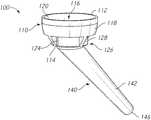
- FIG. 1is a top perspective view of an embodiment of a reverse humeral prosthesis or implant, in accordance with an aspect of the present invention
- FIG. 2is a bottom perspective view of the implant of FIG. 1 , in accordance with an aspect of the present invention
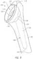
- FIG. 3is a front view of the implant of FIG. 1 , in accordance with an aspect of the present invention.
- FIG. 4is a side view of the implant of FIG. 1 , in accordance with an aspect of the present invention.
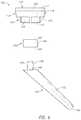
- FIG. 5is an exploded bottom perspective view of the implant of FIG. 1 , in accordance with an aspect of the present invention
- FIG. 6is an exploded side view of the implant of FIG. 1 , in accordance with an aspect of the present invention.
- FIG. 7is an exploded top perspective view of the implant of FIG. 1 , in accordance with an aspect of the present invention.
- FIG. 8is a side view of the implant of FIG. 1 inserted into a portion of a humerus in a first position, in accordance with an aspect of the present invention
- FIG. 9is a side perspective view of the implant of FIG. 1 inserted into a portion of a humerus in a second position, in accordance with an aspect of the present invention.
- FIG. 10is a side view of the implant of FIG. 1 inserted into a portion of a humerus in the second position, in accordance with an aspect of the present invention
- FIG. 11is a cross-sectional side view of another embodiment of a reverse humeral prosthesis or implant, in accordance with an aspect of the present invention.
- FIG. 12is a cross-sectional side view of yet another embodiment of a reverse humeral prosthesis or implant, in accordance with an aspect of the present invention.
- FIG. 13is a side view of another embodiment of a reverse humeral prosthesis or implant, in accordance with an aspect of the present invention.
- FIG. 14is a front view of the implant of FIG. 13 , in accordance with an aspect of the present invention.
- FIG. 15is a back view of the implant of FIG. 13 , in accordance with an aspect of the present invention.
- FIG. 16is a top view of the implant of FIG. 13 , in accordance with an aspect of the present invention.
- FIG. 17is an exploded side view of the implant of FIG. 13 , in accordance with an aspect of the present invention.
- FIG. 18is an exploded front view of the implant of FIG. 13 , in accordance with an aspect of the present invention.
- FIG. 19is an exploded back view of the implant of FIG. 13 , in accordance with an aspect of the present invention.
- FIG. 20is a front view of an adapter of the implant of FIG. 13 , in accordance with an aspect of the present invention.
- FIG. 21is a side view of the adapter of FIG. 20 , in accordance with an aspect of the present invention.
- FIG. 22is a top view of the adapter of FIG. 20 , in accordance with an aspect of the present invention.
- FIG. 23is a bottom view of the adapter of FIG. 20 , in accordance with an aspect of the present invention.
- FIG. 24is a bottom perspective view of the adapter of FIG. 20 , in accordance with an aspect of the present invention.
- FIG. 25is a side view of another adapter of the implant of FIG. 13 , in accordance with an aspect of the present invention.
- FIG. 26is a back view of the adapter of FIG. 25 , in accordance with an aspect of the present invention.
- FIG. 27is a front view of the adapter of FIG. 25 , in accordance with an aspect of the present invention.
- FIG. 28is a top view of the adapter of FIG. 25 , in accordance with an aspect of the present invention.
- FIG. 29is a bottom view of the adapter of FIG. 25 , in accordance with an aspect of the present invention.
- FIG. 30is a bottom perspective view of the adapter of FIG. 25 , in accordance with an aspect of the present invention.
- Methods, systems and devicesfor pre-operatively planned shoulder surgery guides and implants.
- Methods, systems and devicesare provided for the replacement of the shoulder joint wherein the conditions of the humeral and soft tissue envelop is taken into consideration. More specifically, what is considered is that the shape and position of the glenoid and/or humeral implants is not based solely on what can be seen and measured on the scapula, but can be chosen, designed, planned and placed with incorporation of the same information related to the humerus.
- the shoulderis a two part joint, wherein both parts work in conjunction with one another, and the factors that affect performance of the device include factors from both sides of the joint.
- proximal, distal, anterior, posterior, medial, lateral, superior and inferiorare defined by their standard usage for indicating a particular part or portion of a bone or implant according to the relative disposition of the natural bone or directional terms of reference.
- proximalmeans the portion of a device or implant nearest the torso
- distalindicates the portion of the device or implant farthest from the torso.
- anterioris a direction towards the front side of the body
- posteriormeans a direction towards the back side of the body
- medialmeans towards the midline of the body
- lateralis a direction towards the sides or away from the midline of the body
- superiormeans a direction above and “inferior” means a direction below another object or structure.
- positions or directionsmay be used herein with reference to anatomical structures or surfaces.
- the bones of the shoulder and upper armmay be used to describe the surfaces, positions, directions or orientations of the implants and methods.
- the implants and methods, and the aspects, components, features and the like thereof, disclosed hereinare described with respect to one side of the body for brevity purposes.
- the implants and methods, and the aspects, components, features and the like thereof, described and/or illustrated hereinmay be changed, varied, modified, reconfigured or otherwise altered for use or association with another side of the body for a same or similar purpose without departing from the spirit and scope of the invention.
- the implants and methods, and the aspects, components, features and the like thereof, described herein with respect to the right shouldermay be mirrored so that they likewise function with the left shoulder and vice versa.
- the implants and methods, and the aspects, components, features and the like thereof, disclosed hereinare described with respect to the shoulder for brevity purposes, but it should be understood that the implants and methods may be used with other bones of the body having similar structures.
- FIGS. 1-30there are illustrated exemplary embodiments of reverse humeral prostheses or implants 100 , 200 , 300 , 400 .
- Insertion of the implant 100 , 200 , 300 , 400may be optimized using a preoperative plan.
- the preoperative planmay provide the ability to design and surgically implant a reverse humeral prosthesis 100 , 200 , 300 , 400 that is configured or sized and shaped to have a predetermined, neck angle and/or offset.
- a reverse humeral prosthesis 100 , 200 , 300 , 400that is configured or sized and shaped to have a predetermined, neck angle and/or offset.
- neck angle and/or offsetIn order to achieve optimal articular positioning, there must be recognition of and accommodation for the humeral diaphysis and metaphysis offset.
- Appropriate sizing, placement and orientation of the prosthesis 100 , 200 , 300 , 400is crucial to successful outcomes, because misaligned, oversized or “overstuffed” replacement shoulders are more likely to dislocate, loosen, be painful, and/or have decreased range of motion.
- replaced joints where the orientation of the prostheses 100 , 200 , 300 , 400 is improperincreases the likelihood of implant dislocation and loosening.
- the reverse humeral implants 100 , 200 , 300 , 400may also be designed and manufactured to specifically match a patient's anatomy, including humeral and/or glenoid implant size and shape customized to the given patient.
- the customized implants 100 , 200 , 300 , 400may be designed and manufactured taking into account one or more of the following factors: (1) assessment of the reverse humeral implant fit to the humeral bone; (2) relative hardness of the patient bone preoperatively; (3) height and diameter of the reverse humeral cup; (4) orientation, or “offset” of the reverse humeral cup; and (5) optimal bone removal for preservation of soft tissue insertion and attachment.
- the implants 100 , 200 , 300 , 400may be, for example, adaptable reverse humeral implant systems or kits, which may include a stemless reverse cup 110 , 210 , 310 , 410 , a stem 140 , 230 , 330 , 440 , and an intermediate adapter 160 , 250 , 350 , 460 configured or sized and shaped to join or align the stemless reverse cup 110 , 210 , 310 , 410 with the stem 140 , 230 , 330 , 440 .
- the stem 140 , 230 , 330 , 440may be, for example, a relatively short stem as described in greater detail below.
- the adapter 160 , 250 , 350 , 460may be, for example, configured or sized and shaped to achieve a desired offset or angle between the cup 110 , 210 , 310 , 410 and stem 140 , 230 , 330 , 440 .
- the adapter 160 , 250 , 350 , 460may also, for example, be a dual taper adapter that is configured or sized and shaped to provide for angle customization and/or offset customization.
- the angle and/or offset customizationmay take into account, for example, patient anatomy, humeral size, humeral diaphysis, and metaphysis offset.
- the adapter 160 , 250 , 350 , 460may be configured or sized and shaped based on the following: (1) position the metaphysis; (2) assess the diaphysis; (3) determine the optimal humeral implant; (4) conceive the adapter based on these assessments; and (5) confirm constraints are met.
- the adapter 160 , 250 , 350 , 460may also be configured or sized and shaped based on the measurements for improved fixation strength and/or overall construct range of motion.
- the implant 100includes a stemless reverse cup 110 for implantation in the proximal part of a humerus 190 , a stem 140 , and an adapter 160 to couple the cup 110 and the stem 140 .
- a reverse humeral implantprovides a concave surface on the humeral head configured or sized and shaped to articulate with a convex head attached to the glenoid region of the scapula.
- the stemless reverse cup 110may have a first end 112 and a second end 114 .
- the terms “stemless reverse cup,” “proximal reverse cup,” “proximal cup,” “proximal cup portion,” “proximal cup component” and “cup”may be used interchangeably herein as they each refer to the portion of a shoulder implant that engages the glenoid or glenoid replacement.
- the cup 110may include a generally cup-shaped housing 116 with an outer cylindrical wall 118 defining a recess 122 on an upper surface 120 and a base portion 126 extending away from a bottom surface, lower surface or backside 124 of the cup-shaped housing 116 , as shown in FIG. 7 .
- the recess 122may extend into the housing 116 from the first end 112 toward the second end 114 of the cup 110 .
- the base portion 126may extend out from the second end 114 of the cup 110 .
- the recess 122may be configured or sized and shaped to receive and securely hold, for example, a cup liner (not shown) made of polyethylene or another material as known by one of skill in the art.
- the cup liner (not shown)may be configured or sized and shaped to snap fit into the recess 122 .
- the cup liner (not shown)may also have a concave articular surface to allow for the cup liner (not shown) to articulate with a convex head attached to, for example, the glenoid part of the scapula.
- the stemless reverse cup 110may also include, for example, ribs, fins, or projections 128 extending away from the bottom surface 124 .
- the ribs 128may include a surface or rib-like structure projecting from the outer cylindrical wall 118 of the reverse cup 110 .
- the ribs 128may project from the surface of the outer cylindrical wall 118 in, for example, a generally perpendicular orientation.
- the ribs 128may also be configured or sized and shaped to provide rotational control under a torsional load, i.e., resist or prevent twisting or turning of the reverse cup 110 within the implant site after implantation.
- the stemless reverse cup 110may optionally be made of a metallic material, such as for example, stainless steel, cobalt-chromium, titanium alloy, or any other like material as known by one of ordinary skill in the art. It is also contemplated that the stemless reverse cup 110 may include a metallic and/or biological porous coating to enhance bony integration.
- the biological porous coatingmay be, for example, pure HA, pure TCP, or a mix of HA/TCP.
- the stemless reverse cup 110may be formed through additive manufacturing of a monolithic component.
- the monolithic componentmay include an internal plain wall partially covered on the external surfaces with a porous metallic structure. Each of the porous structure sections may include an annular plain surface distally helping the surgeon to drive the implant 100 into the bone.
- the stemless reverse cup 110may also be a monolithic component with a concave, spherical articular surface on an upper surface 120 of the reverse cup 110 .
- the concave, spherical articular surfacemay articulate with a convex spherical head attached to the glenoid part of the scapula and on a base portion a surface enhanced for bony integration.
- the monolithic cup 110may be made of, for example, a polymer, such as, PEEK, polyethylene, polyurethane, and the like as known by one of skill in the art.
- the monolithic cup 110may also include, for example, a metallic coating on the bony facing surface.
- the recess 122may also be configured or sized and shaped to receive and securely hold a universal adapter (not shown) which may be configured or sized and shaped to snap fit into the recess 122 .
- the universal adapter(not shown) may have a convex surface which articulates against a concave surface of a glenoid or which articulates with a concave surface attached to the glenoid part of the scapula.
- the universal adapter (not shown)may also include a means for engaging another component that has a convex surface.
- the lower portion or backside 124 of the stemless reverse cup 110may also include an opening 130 .
- the opening 130may be configured to or sized and shaped to receive an adapter 160 .
- the opening 130may include, for example, a receiving portion 132 built into the lower portion of the cup 110 , as shown in FIG. 7 .
- the receiving portion 132may be, for example, substantially cylindrical.
- the opening 130may have an inner wall with, for example, a tapered diameter (not shown) and may be configured to receive a similarly tapered adapter 160 , as shown in FIG. 6 .
- the implant 100may include a connection means (not shown) between the adapter 160 and the cup 110 .
- the connection meansmay include, for example, a screw, a press fit configuration without a taper, a press fit configuration with a taper, and/or a snap ring.
- the reverse humeral implant 100may also include the stem 140 .
- the terms “stem,” “distal stem,” “distal stem portion,” “stem portion,” “distal stem component,” “stem component”may be used interchangeably herein as they each refer to the portion of the shoulder implant that is inserted into at least a portion of the humeral canal.
- the stem 140may be configured to be implanted within the humerus 190 , for example, extending into the epiphysis and diaphysis of the humerus 190 , as shown in FIGS. 8-10 .
- the stem 140may be, for example, a relatively short stem compared to the stems used in existing traditional prosthetic devices.
- the short stem 140may be, for example, less than about 80 mm, whereas a typical stem is about 80 mm to about 120 mm, and a long stem is about 120 mm or more.
- the stem 140 of the reverse humeral implant 100may include a shaft portion 142 with a first end 144 configured or sized and shaped to adjoin the adapter 160 and a second terminal end 146 .
- the first end 144may include, for example, a joining member 148 configured or sized and shaped to press fit or otherwise adjoin with the adapter 160 .
- the joining member 148may include a substantially cylindrical structure 150 projecting from the first end 144 of the stem 140 .
- the cylindrical structure 150 of the joining member 148may have, for example, a tapered outer diameter and be configured or sized and shaped to engage a similarly cylindrical and tapered opening 168 in the adapter 160 . As shown in FIGS. 1-10 , the joining member 148 may also project from the first end 144 of the stem 140 at a desired angle to orient the stem 140 in a desired position with respect to the adapter 160 and the cup 110 . It is also contemplated that the joining member 148 may be, for example, a female joining member configured or sized and shaped to engage a similarly male structure projecting from the distal end of the adapter, such as shown in FIG. 12 and described in greater detail below.
- the adapter 160 of the reverse humeral implant 100may include an intermediate dual taper.
- the intermediate dual tapered adapter 160may be configured or sized and shaped to join or align the stemless reverse cup 110 with the stem 140 .
- the outer diameter of the cylindrical member 166 of the adapter 160may be tapered.
- the lower portion or backside 124 of the stemless reverse cup 110may include an opening 130 configured or sized and shaped to receive the first end 162 of the adapter 160 .
- the opening 130may include an inner wall 134 with, for example, a tapered diameter that has a taper similar to the taper of the outer diameter of the cylindrical member 166 .
- the tapered outer diameter of the adapter 160 and the tapered inner diameter of the backside 124 of the cup 110allow for the adapter 160 to be press fitted or otherwise forced into the opening 130 of the reverse cup 110 to securely engage the adapter 160 with the cup 110 during implantation of the prosthetic device 100 .
- the adapter 160may also include a substantially cylindrical member 166 with an opening 168 at one end of the cylinder 166 .
- the opening 168may, for example, extend into only a portion of the adapter 160 or, alternatively, the opening 168 may extend through the entire length of the cylinder 166 .
- the opening 168may be configured or sized and shaped to receive a joining member 148 , for example, a male joining member, of the stem 140 .
- the opening 168 of the adapter 160may include a cylindrical opening with a diameter that is tapered.
- the tapered opening 168may be configured or sized and shaped to receive a similarly tapered joining member 148 of the stem 140 .
- the tapered inner diameter of the adapter 160may be, for example, press fit with the tapered joining member 148 of the stem 140 .
- the tapered outer diameter and tapered inner diameter of the adapter 160may be referred to as a dual-tapered design.
- Each taper of the dual-tapered designmay be, for example, infinitely dialable or adjustable.
- engagement of at least one of the tapers of the dual-tapered designmay be restricted to a discrete number of angular positions.
- the adapter 160may be configured to achieve a desired offset or angle between the cup 110 and stem 140 .
- the dual taper adapter 160may be configured or sized and shaped to provide angle customization and/or offset customization.
- the angle customization and/or offset customizationmay take into account one or more of, for example, the patient anatomy, humeral size, humeral diaphysis, and metaphysis offset.
- the adapter 160may also be, for example, configured to achieve a desired offset or angle between the cup 110 and stem 140 .
- the opening 168may be positioned offset from a center point or central axis of the adapter 160 .
- the exterior size and shape of the adaptermay provide the angulation of the cup 110 with respect to the stem 140 .
- the cup 110may be offset or angled with respect to a central axis of the joining member 148 of the stem 140 .
- the opening 168may be positioned at an angle to the central axis of the adapter 160 .
- the reverse humeral implant 200may include a stemless reverse cup 210 , a stem 230 , and an adapter 250 for coupling the cup 210 and the stem 230 .
- the terms “stemless reverse cup,” “proximal reverse cup,” “proximal cup,” “proximal cup portion,” “proximal cup component” and “cup”may be used interchangeably herein as they each refer to the portion of a shoulder implant that engages the glenoid or glenoid replacement.
- the terms “stem,” “distal stem,” “distal stem portion,” “stem portion,” “distal stem component,” “stem component”may be used interchangeably herein as they each refer to the portion of the shoulder implant that is inserted into at least a portion of the humeral canal.
- the cup 210may include a first end 212 and a second end 214 .
- the cup 210may also include a recess or interior surface 216 and a backside, exterior surface or outer surface 218 .
- the interior surface 216may be positioned at and extend into the first end 212 of the cup 210 .
- the interior surface 216may be a concave surface on the humeral head configured or sized and shaped to receive and articulate with a convex head attached to the glenoid region of the scapula.
- the backside 218may extend from the first end 212 to the second end 214 on the exterior of the cup 210 and may be configured or sized and shaped to be received within the head of a humerus.
- the cup 210may also include a base portion 220 at the second end 214 of the cup 210 . The base portion 220 may extend away from the backside 218 of the cup 210 .
- the base portion 220may include a flange 222 and a recess or opening 224 extending into the cup 210 inside of the flange portion 222 .
- the flange 222may be, for example, a circumferential flange extending around at least a portion of the backside 218 of the cup 210 .
- the stem 230may have a first end 232 and a second end 234 .
- the stem 230may include a base portion 236 extending from the second end 234 toward the first end 232 and a joining member 238 at the first end 232 .
- the joining member 238may be, for example, a male joining member 238 as shown in FIG. 11 .
- the joining member 238may include an outer diameter 240 , for example, smaller than the outer diameter of the base portion 236 .
- the outer diameter 240 of the joining member 238may, for example, taper as it extends away from the base portion 236 .
- the adapter 250may have a first end 252 and a second end 254 , as shown in FIG. 11 .
- the first end 252may be configured or sized and shaped to couple to the cup 210 and the second end 254 may be configured or sized and shaped to couple to the stem 230 .
- the adapter 250may include a receiving portion 256 with a groove 258 inset into the first end 252 of the adapter 250 .
- the groove 258may be, for example, a circumferential groove inset into a portion of the adapter 250 .
- the groove 258may be, for example, designed or sized and shaped to mate with the flange 222 of the cup 210 .
- the adapter 250may also include an opening 260 extending into at least a portion of the adapter from the second end 254 . As shown in FIG. 11 , the opening 260 may pass through the entire length of the adapter.
- the opening 260may be configured or sized and shaped to receive the joining member 238 of the stem 230 .
- the opening 260may be, for example, a cylindrical opening with a diameter that is tapered.
- the tapered opening 260may be, for example, configured or sized and shaped to receive a similarly tapered joining member 238 of the stem 230 by press fitting the adapter 250 and stem 230 together.
- the adapter 250may also be, for example, configured to achieve a desired offset or angle between the cup 210 and the stem 230 .
- the opening 260may be positioned offset from a center point or central axis of the adapter 250 .
- the exterior size and shape of the adapter 250may provide the angulation of the cup 210 with respect to the stem 230 .
- the opening 260may be positioned at an angle to the central axis of the adapter 250 .
- the adaptermay be configured for angle customization and/or offset customization based on, for example, patient anatomy, humeral size, humeral diaphysis, and metaphysis offset.
- the adapter 250may offset or angle the cup 210 relative to the longitudinal axis of the joining member 238 of the stem 230 .
- the implant 300may include a stemless reverse cup 310 , a stem 330 , and an adapter 350 .
- the terms “stemless reverse cup,” “proximal reverse cup,” “proximal cup,” “proximal cup portion,” “proximal cup component” and “cup”may be used interchangeably herein as they each refer to the portion of a shoulder implant that engages the glenoid or glenoid replacement.
- the terms “stem,” “distal stem,” “distal stem portion,” “stem portion,” “distal stem component,” “stem component”may be used interchangeably herein as they each refer to the portion of the shoulder implant that is inserted into at least a portion of the humeral canal.
- the cup 310may include a first end 312 and a second end 314 .
- the cup 310may also include a recess or interior surface 316 and a backside, exterior surface or outer surface 318 .
- the interior surface 316may be positioned at and extend into the first end 312 of the cup 310 .
- the interior surface 316may be a concave surface on the humeral head configured or sized and shaped to receive and articulate with a convex head attached to the glenoid region of the scapula.
- the backside 318may extend from the first end 312 to the second end 314 on the exterior of the cup 310 and may be configured or sized and shaped to be received within the head of a humerus.
- the cup 310may also include a base portion 320 at the second end 314 of the cup 310 .
- the base portion 320may extend away from the backside 318 of the cup 310 .
- the base portion 320may include at least one tongue, projection, or flange 322 and a recess or opening 324 positioned between the at least one projection 322 .
- the at least one projection 322may be, for example, a circumferential flange extending around at least a portion of the backside 318 of the cup 310 .
- the stem 330may have a first end 332 and a second end 334 .
- the stem 330may include a base portion 336 extending from the second end 334 toward the first end 332 and a joining member 338 at the first end 332 .
- the joining member 338may be, for example, a female joining member 338 forming an opening 340 , as shown in FIG. 12 , for receiving a portion of the adapter 350 .
- the opening 340may include an interior or inner surface 342 with a diameter, for example, smaller than the outer diameter of the base portion 336 .
- the walls of the interior surface 342 of the opening 340may, for example, taper as they extend into the base portion 336 .
- the adapter 350may have a first end 352 and a second end 354 , as shown in FIG. 12 .
- the first end 352may be configured or sized and shaped to couple to the cup 310 and the second end 354 may be configured or sized and shaped to couple to the stem 330 .
- the adapter 350may include a receiving portion 356 with at least one recess or groove 358 inset into the first end 352 of the adapter 350 .
- the at least one groove 358may be, for example, a circumferential groove inset into a portion of the adapter 350 .
- the groove 358may be, for example, designed or sized and shaped to mate with the at least one projection 322 extending from the lower portion or backside 318 of the stemless reverse cup 310 .
- the adapter 350may also include a joining member 360 , for example, a male joining member or tongue 360 extending away from the second end 354 of the adapter 350 .
- the joining member 360may be configured or sized and shaped to fit into the joining member or at least one groove 338 in an upper end 332 of the stem 230 .
- the joining member 360may be, for example, a cylindrical projection 360 with a diameter that is tapered as it extends away from the second end 354 of the adapter 350 .
- the tapered joining member 360may be, for example, configured or sized and shaped to receive a similarly tapered opening 340 in the stem 330 by press fitting the adapter 350 and stem 330 together.
- the adapter 350may also be, for example, configured to achieve a desired offset or angle between the cup 310 and stem 330 .
- the joining member 360may be positioned offset from a center point or central axis of the adapter 350 .
- the exterior size and shape of the adaptermay provide the angulation of the cup 310 with respect to the stem 330 .
- the joining member 360may be positioned at an angle to the central axis of the adapter 350 .
- the adapter 350may be configured for angle customization and/or offset customization based on, for example, patient anatomy, humeral size, humeral diaphysis, and metaphysis offset.
- the reverse humeral implant 400may include a stemless reverse cup 410 , a stem 440 , an adapter 460 for coupling the cup 410 and the stem 440 , and an articulating cup liner 480 .
- the terms “stemless reverse cup,” “proximal reverse cup,” “proximal cup,” “proximal cup portion,” “proximal cup component” and “cup”may be used interchangeably herein as they each refer to the portion of a shoulder implant that engages the glenoid or glenoid replacement.
- stemdistal stem
- distal stem portiondistal stem portion
- distal stem componentdistal stem component
- the cup 410may include a first end 412 and a second end 414 .
- the cup 410may also include a recess or interior surface 416 and a backside, exterior surface or outer surface 418 .
- the interior surface 416may be positioned at and extend into the first end 412 of the cup 410 .
- the interior surface 416may be configured or sized and shaped to receive an articulating liner 480 which can receive a convex head attached to the glenoid region of the scapula.
- the backside 418may extend from the first end 412 to the second end 414 on the exterior of the cup 410 and may be configured or sized and shaped to be received within the head of a humerus.
- the cup 410may include an upper interior surface 420 with a recess 422 extending into the cup 410 for receiving a snap ring 490 .
- the recess 422may be configured or sized and shaped to receive and securely hold, for example, a liner 480 made of polyethylene or another material as known by one of skill in the art.
- the liner 480may be configured or sized and shaped to snap fit into the recess 422 .
- the liner 480may also have a concave articular surface 486 to allow for the liner 480 to articulate with a convex head attached to, for example, the glenoid part of the scapula.
- the cup 410may also include at least one protrusion 424 extending away from the first end 412 of the cup 410 .
- the at least one protrusion 424aligns with and engages a corresponding recess 488 in the liner 480 .
- the cup 410may also include, for example, a base portion 426 with at least one fin, rib, or projection 428 extending away from the base portion 426 .
- the ribs 428may include a surface or rib-like structure projecting from the base portion 426 of the reverse cup 410 .
- the ribs 428may project from the surface of the base portion 426 in, for example, a generally perpendicular orientation.
- the ribs 428may also be configured or sized and shaped to provide rotational control under a torsional load, i.e., resist or prevent twisting or turning of the reverse cup 410 within the implant site after implantation.
- the stemless reverse cup 410may optionally be made of a metallic material, such as for example, stainless steel, cobalt-chromium, titanium alloy, or any other like material as known by one of ordinary skill in the art. It is also contemplated that the stemless reverse cup 410 may include a metallic and/or biological porous coating to enhance bony integration.
- the biological porous coatingmay be, for example, pure HA, pure TCP, or a mix of HA/TCP.
- the stem 440may have a first end 442 and a second end 444 .
- the stem 440may include a base portion 446 extending from the second end 444 toward the first end 442 and a joining member 448 at the first end 442 .
- the joining member 448may be, for example, a male joining member 448 , as shown in FIGS. 17-19 .
- the joining member 448may include an outer diameter 450 , for example, smaller than the outer diameter of the base portion 446 .
- the outer diameter 450 of the joining member 448may, for example, taper as it extends away from the base portion 446 .
- the adapter 460may have a first end 462 and a second end 464 .
- the first end 462may be configured or sized and shaped to couple to the cup 410 and the second end 464 may be configured or sized and shaped to couple to the stem 440 .
- the adapter 460may include at least one hole 466 inset into the first end 462 of the adapter 460 .
- the at least one hole 466may be, for example, designed or sized and shaped to secure the cup 410 to the adapter 460 .
- the adapter 460may also include an opening 468 extending into at least a portion of the adapter 460 from the second end 464 . As shown in FIGS.
- the opening 468may pass through the entire length of the adapter 460 .
- the opening 468may be configured or sized and shaped to receive the joining member 448 of the stem 440 .
- the opening 468may be, for example, a cylindrical opening with a diameter that is tapered.
- the tapered opening 468may be, for example, configured or sized and shaped to receive a similarly tapered joining member 448 of the stem 440 by press fitting the adapter 460 and stem 440 together.
- the opening 468may extend through the adapter 460 , for example, along the central axis of the adapter 460 , as shown in FIGS.
- the opening 468may be offset from the center point or central axis of the adapter 460 , such as shown in FIGS. 28-30 .
- the position of the opening 468may be selected to achieve a desired offset between the cup 410 and stem 440 , along a longitudinal axis of the joining member 448 of the stem 440 .
- the adapter 460 , 460 ′may include a first set of feet, protrusions, or projections 472 , 472 ′ and a second set of feet, protrusions, or projections 474 , 474 ′.
- each of the feet 472 , 474may, for example, have the same width and extend away from the second end 464 of the adapter 460 the same distance.
- FIGS. 20-24each of the feet 472 , 474 may, for example, have the same width and extend away from the second end 464 of the adapter 460 the same distance.
- the first feet 472 ′may, for example, have a first width and extend away from the second end 464 ′ a first distance and the second feet 474 ′ may, for example, have a second width and extend away from the second end 464 ′ a second distance.
- the first distancemay be, for example, smaller than the second distance.
- the first widthmay be smaller than the second width.
- the varying width of the first feet 472 ′ compared to the second feet 474 ′allows for the adapter to provide angulation of the cup 410 with respect to a longitudinal axis of the joining member 448 of the stem 440 .
- the adapter 460may be configured for angle customization and/or offset customization based on, for example, patient anatomy, humeral size, humeral diaphysis, and metaphysis offset.
- the articulating cup liner 480may include a first end 482 and a second end 484 .
- the liner 480may include an articulating surface 486 at the first end 482 .
- the liner 480may include grooves 488 around the exterior surface of the liner 480 at the first end 482 and the grooves 488 may open toward the second end 484 .
- the grooves 488may be sized and shaped to receive the protrusions 424 on the cup 410 to assist with aligning and coupling the liner 480 to the cup 410 .
- the liner 480may further include a groove or recess 489 extending around a portion of the liner 480 near the second end 484 for receiving a snap ring 490 , as shown in FIGS. 17 and 19 .
- a portion of the snap ring 490may be inserted into the groove 489 in the liner 480 and a portion of the snap ring 490 may fit into the recess 422 in the cup 410 to secure the liner 480 to the cup 410 .
- one or more of the components of the prosthetic devices and systems 100 , 200 , 300 , 400 disclosed hereincan be customized or patient specific.
- the below methods, analyses and optimizations, including associated computer readable medium and 3D printing devicescan be used to develop and create patient specific shoulder implant devices 100 , 200 , 300 , 400 , including the disclosed prosthetic including an inlay stemless reverse cup 110 , 210 , 310 , 410 , a stem 140 , 230 , 330 , 440 , and an intermediate dual taper adapter 160 , 250 , 350 , 460 .
- a patient specific or customized intermediate dual taper adapter 160 , 250 , 350 , 460may include a desired angle and/or offset based on the methods of analysis and optimization disclosed herein.
- the angle and/or offset of the stem 140 , 230 , 330 , 440 when connected to the cup 110 , 210 , 310 , 410 by way of the adapter 160 , 250 , 350 , 460may be calculated based on an analysis of a patient's humeral diaphysis and metaphysis offset, among other things, using one or more pre-operative planning approaches disclosed herein.
- a humeral implant 100 , 200 , 300 , 400including, for example, a cup 110 , 210 , 310 , 410 , an adapter 160 , 250 , 350 , 460 and a stem 140 , 230 , 330 , 640 may be customized based on pre-operative planning. At least one of the cup 110 , 210 , 310 , 410 , the adapter 160 , 250 , 350 , 460 , and the stem 140 , 230 , 330 , 440 may be customized. If only some of the components are customized, then, the remaining components may be at least one of “off-the-shelf” and standardized.
- the cup 110 , 210 , 310 , 410 and stem 140 , 230 , 330 , 430may be standardized, or come in an array of standardized shapes and sizes for selection as appropriate to the patient, while the adapter 160 , 250 , 350 , 460 can be customized for each patient.
- the cups 110 , 210 , 310 , 410 , adapters 160 , 250 , 350 , 460 , and stems 140 , 230 , 330 , 430 whether customized or standardizedmay be, for example, 3D printed.
- Pre-operative planning methods and systemsare also provided for selecting and/or designing a shoulder implant, including for example the prosthetic devices 100 , 200 , 300 , 400 and systems disclosed herein.
- Such pre-operative planningmay in some aspects take into consideration a plurality of factors and assessments, including, for example, one or more of the following, the combination and order of which may vary:
- analyzing the joint lineincluding comparing the premorbid joint line and the pathologic joint line and the new joint line, with the new joint line being as similar to a joint line defined based on several factors including the difference between the premorbid joint line and the pathologic joint line;
- determining the best fit size of implantfrom a range of sizes (length of stem, diameter of stem, diameter of stemless cup, height of stemless cup, height of humeral liner, diameter of humeral liner, offset and angle of adapter, diameter of adapter, height of adapter, radius of curvature of the articular surface);
- range of motion analysisincluding virtually positioning implants through extreme ranges of motion to measure impact locations and compensate for necessary functional range of motion, wherein range of motion analysis can comprise optimization of adduction and/or abduction, elevation, flexion, extension, external and internal rotation range, and complex compound movements;
- conducting soft tissue analysiscomprising determining key soft tissue insertion points, measuring distances in three dimensions for comparison to pre-operative conditions, and assessing lengths at extreme ranges of motion, such that total soft tissue length change or contraction is substantially maintained within anatomical ranges in order to substantially achieve most common activities of daily living;
- a graftfor example, graft thickness
- analyzing the joint linemay include comparing the premorbid joint line, the pathologic joint line and the new joint line and analyzing the humeral lateralization.
- Humeral lateralizationmay be determined by the distance the humeral shaft is moved laterally relative to the scapula after the implants are placed.
- the above method of creating a shoulder surgery guide based on pre-operative planningmay further include one or more of the below optimization limitations.
- optimization limitationmay include, for example, the identification of procedural risks based on measurements of whether: the glenoid face coverage is maximized; the overhang of the glenoid face is minimized; the bone removal on the glenoid face is minimized, such as for example less than about 2 mm of depth; the glenoid retroversion is less than about 5 degrees; the “seating” of the glenoid implant is greater than about 80%, i.e.
- any glenoid implant augment featureis as minimal as possible; there is less than about 1 mm of difference between the premorbid or the pathologic joint line and the new joint line with implants; there is minimized penetration of the glenoid cortical wall medially; there is maximized bone thickness behind glenoid, preferably greater than 3 mm; the orientation offset between the native glenoid and implant superior/inferior axis is minimized, preferably less than 5 degrees; the superior or inferior tilt versus anatomy is minimized, preferably less than 5 degrees; there is less than about 5% change in soft tissue length at extreme ranges of motion; there is an absence of a humeral cortical wall penetration by any portion of the humeral implant; there is minimal difference in diameter in the cut plane between the humeral stemless cup and the internal diameter of the humeral cortical wall, for example, less than 3 mm; there is greater tuberosity to medial head
- the above methodmay further include recommending implants and placement positions, with recommended adjustments in glenoid implant size, augmentation depth, augment position, positioning in six degrees of freedom, fixation type, fixation size, reaming depth, reaming diameter, and reaming angle(s), seating ratio, wherein the reaming angles may include retroversion and inclination.
- the above methodmay further include recommending implants and placement positions, with recommended adjustments in humerus stem size, length, head diameter, head height, head offset, rotation (axial), humeral diaphysis and metaphysis offset.
- the method of creating a patient specific adapter for the disclosed humeral implantincludes: utilizing one or more of the above limitations, analyses, optimizations and recommendations to create an adaptable humeral offset prosthesis.
- Such prosthetic creationmay include automated design and creation of a three dimensional model of a glenoid and/or humeral guide reflecting one or more optimized parameters determined during pre-operative planning based on the above described method.
- the subject matter described hereinmay be implemented in software in combination with hardware and/or firmware.
- the subject matter described hereinmay be implemented in software executed by a processor.
- the subject matter described hereinmay be implemented using a computer readable medium having stored thereon computer executable instructions that when executed by the processor of a computer control the computer to perform steps.
- Exemplary computer readable media suitable for implementing the subject matter described hereininclude non-transitory devices, such as disk memory devices, chip memory devices, programmable logic devices, and application specific integrated circuits.
- a computer readable medium that implements the subject matter described hereinmay be located on a single device or computing platform or may be distributed across multiple devices or computing platforms.
- noderefers to a physical computing platform including one or more processors and memory.
- the terms “function” or “module”refer to hardware, firmware, or software in combination with hardware and/or firmware for implementing features described herein.
- a computer readable mediumhaving stored thereon executable instructions that when executed by the processor of a computer, control the computer to perform steps including generating a virtual three dimensional model of a glenoid and/or humeral guide reflecting one or more optimized parameters determined during pre-operative planning based on the above described method.
- a computer readable mediumis provided, having stored thereon executable instructions that when executed by the processor of a computer control a 3D printing device in communication with the computer, whereby the 3D printing device prints a humeral prosthesis or component thereof, e.g. adapter, for use in shoulder replacement surgery in a patient for which the optimization analysis was conducted.
- methods of treating a patient, and/or surgical methodsare provided, wherein one or more of the disclosed methods of analysis and optimization are performed on a patient in need of shoulder or other joint surgery.
- the methods of treating a patientmay include performing analysis and optimization, designing and creating an optimized prosthesis, or selecting from an array.
- the method of treating a patientmay also include utilizing the pre-operative planning to design and optimize one or more glenoid and/or humeral implants and surgically implanting the one or more glenoid and/or humeral prosthetic devices.
- kitsmay also be provided, wherein the kit may include a set of instructions for performing the disclosed pre-operative planning methods and analyses.
- a kitmay further include one or more glenoid and/or humeral prosthetic devices, wherein the devices are customizable or modular in design such that the prosthetic device can be optimized for the patient based on the pre-operative planning analysis.
- the kitmay further have a guide for placing a prosthetic device during shoulder surgery, wherein the guide can be optimized for the patient based on the pre-operative planning analysis.
- the kitmay also use a 3-D printing device for producing a guide and/or one or more glenoid and/or humeral prosthetic devices.
- the kitmay include a computer-readable medium (software) for use in conducting the pre-operative planning, and designing a guide, glenoid implant and/or humeral implant based on input parameters gathered during the disclosed methods of analysis.
- the patientmay be a mammalian subject.
- the patientmay be a human subject, including an adult, adolescent or child.
- a method or device that “comprises,” “has,” “includes,” or “contains” one or more steps or elementspossesses those one or more steps or elements, but is not limited to possessing only those one or more steps or elements.
- a step of a method or an element of a device that “comprises,” “has,” “includes,” or “contains” one or more featurespossesses those one or more features, but is not limited to possessing only those one or more features.
- a device or structure that is configured in a certain wayis configured in at least that way, but may also be configured in ways that are not listed.
Landscapes
- Health & Medical Sciences (AREA)
- Engineering & Computer Science (AREA)
- Life Sciences & Earth Sciences (AREA)
- Public Health (AREA)
- Biomedical Technology (AREA)
- Veterinary Medicine (AREA)
- General Health & Medical Sciences (AREA)
- Animal Behavior & Ethology (AREA)
- Heart & Thoracic Surgery (AREA)
- Transplantation (AREA)
- Orthopedic Medicine & Surgery (AREA)
- Vascular Medicine (AREA)
- Cardiology (AREA)
- Oral & Maxillofacial Surgery (AREA)
- Surgery (AREA)
- Manufacturing & Machinery (AREA)
- Chemical & Material Sciences (AREA)
- Materials Engineering (AREA)
- Nuclear Medicine, Radiotherapy & Molecular Imaging (AREA)
- Robotics (AREA)
- Medical Informatics (AREA)
- Molecular Biology (AREA)
- Prostheses (AREA)
Abstract
Description
Claims (18)
Priority Applications (3)
| Application Number | Priority Date | Filing Date | Title |
|---|---|---|---|
| US16/164,555US10987226B2 (en) | 2016-04-19 | 2018-10-18 | Pre-operatively planned humeral implant and planning method |
| US17/215,242US12109120B2 (en) | 2016-04-19 | 2021-03-29 | Pre-operatively planned humeral implant and planning method |
| US18/826,767US20240423808A1 (en) | 2016-04-19 | 2024-09-06 | Pre-operatively planned humeral implant and planning method |
Applications Claiming Priority (3)
| Application Number | Priority Date | Filing Date | Title |
|---|---|---|---|
| US201662324372P | 2016-04-19 | 2016-04-19 | |
| PCT/US2017/028470WO2017184792A1 (en) | 2016-04-19 | 2017-04-19 | Pre-operatively planned humeral implant and planning method |
| US16/164,555US10987226B2 (en) | 2016-04-19 | 2018-10-18 | Pre-operatively planned humeral implant and planning method |
Related Parent Applications (1)
| Application Number | Title | Priority Date | Filing Date |
|---|---|---|---|
| PCT/US2017/028470ContinuationWO2017184792A1 (en) | 2016-04-19 | 2017-04-19 | Pre-operatively planned humeral implant and planning method |
Related Child Applications (1)
| Application Number | Title | Priority Date | Filing Date |
|---|---|---|---|
| US17/215,242ContinuationUS12109120B2 (en) | 2016-04-19 | 2021-03-29 | Pre-operatively planned humeral implant and planning method |
Publications (2)
| Publication Number | Publication Date |
|---|---|
| US20190046326A1 US20190046326A1 (en) | 2019-02-14 |
| US10987226B2true US10987226B2 (en) | 2021-04-27 |
Family
ID=58672709
Family Applications (3)
| Application Number | Title | Priority Date | Filing Date |
|---|---|---|---|
| US16/164,555Active2038-01-12US10987226B2 (en) | 2016-04-19 | 2018-10-18 | Pre-operatively planned humeral implant and planning method |
| US17/215,242Active2038-11-14US12109120B2 (en) | 2016-04-19 | 2021-03-29 | Pre-operatively planned humeral implant and planning method |
| US18/826,767PendingUS20240423808A1 (en) | 2016-04-19 | 2024-09-06 | Pre-operatively planned humeral implant and planning method |
Family Applications After (2)
| Application Number | Title | Priority Date | Filing Date |
|---|---|---|---|
| US17/215,242Active2038-11-14US12109120B2 (en) | 2016-04-19 | 2021-03-29 | Pre-operatively planned humeral implant and planning method |
| US18/826,767PendingUS20240423808A1 (en) | 2016-04-19 | 2024-09-06 | Pre-operatively planned humeral implant and planning method |
Country Status (5)
| Country | Link |
|---|---|
| US (3) | US10987226B2 (en) |
| EP (1) | EP3445292B1 (en) |
| AU (2) | AU2017253113B2 (en) |
| CA (1) | CA3059036A1 (en) |
| WO (1) | WO2017184792A1 (en) |
Cited By (3)
| Publication number | Priority date | Publication date | Assignee | Title |
|---|---|---|---|---|
| US20230145329A1 (en)* | 2021-11-11 | 2023-05-11 | Arthrex, Inc. | Arthroplasty implant systems with stemless implants |
| US12109120B2 (en) | 2016-04-19 | 2024-10-08 | Stryker European Operations Limited | Pre-operatively planned humeral implant and planning method |
| US12268610B2 (en) | 2020-05-07 | 2025-04-08 | Howmedica Osteonics Corp. | Stemless metaphyseal humeral implant |
Families Citing this family (44)
| Publication number | Priority date | Publication date | Assignee | Title |
|---|---|---|---|---|
| US20230080207A1 (en) | 2005-02-25 | 2023-03-16 | Shoulder Innovations, Inc. | Methods and devices for less invasive glenoid replacement |
| US8778028B2 (en) | 2005-02-25 | 2014-07-15 | Shoulder Innovations, Inc. | Methods and devices for less invasive glenoid replacement |
| WO2007109340A2 (en) | 2006-03-21 | 2007-09-27 | Axiom Orthopaedics, Inc. | Femoral and humeral stem geometry and implantation method for orthopedic joint reconstruction |
| FR2932674B1 (en) | 2008-06-20 | 2011-11-18 | Tornier Sa | METHOD FOR MODELING A GLENOIDAL SURFACE OF AN OMOPLATE, DEVICE FOR IMPLANTING A GLENOIDAL COMPONENT OF A SHOULDER PROSTHESIS, AND METHOD FOR MANUFACTURING SUCH COMPOUND |
| USD685474S1 (en) | 2010-07-06 | 2013-07-02 | Tornier, Inc. | Prosthesis anchor |
| FR2978912A1 (en) | 2011-08-10 | 2013-02-15 | Tornier Inc | ANCILLARY EXTRACTION OF A PROSTHESIS |
| EP2586387A1 (en) | 2011-10-31 | 2013-05-01 | Tornier Orthopedics Ireland Ltd. | Bone reamer |
| BR112015007174A8 (en) | 2012-10-29 | 2018-04-24 | Tornier Orthopedics Ireland Ltd | Modular reverse shoulder prosthesis and respective systems |
| EP3057524B1 (en) | 2013-10-10 | 2019-11-20 | Imascap | Method for designing and producing a shoulder surgery guide |
| EP3925574A1 (en) | 2013-11-08 | 2021-12-22 | Imascap | Pre-operatively planned adaptive glenoid implants and method for planning its design |
| US10405993B2 (en) | 2013-11-13 | 2019-09-10 | Tornier Sas | Shoulder patient specific instrument |
| US12023253B2 (en) | 2014-01-24 | 2024-07-02 | Howmedica Osteonics Corp. | Humeral implant anchor system |
| US10456264B2 (en) | 2014-01-24 | 2019-10-29 | Tornier, Inc. | Humeral implant anchor system |
| FR3029769A1 (en) | 2014-12-10 | 2016-06-17 | Tornier Sa | KIT FOR A PROSTHESIS OF SHOULDER |
| EP3389513A1 (en) | 2015-12-16 | 2018-10-24 | Tornier, Inc. | Patient specific instruments and methods for joint prosthesis |
| US11833055B2 (en) | 2016-02-28 | 2023-12-05 | Integrated Shoulder Collaboration, Inc. | Shoulder arthroplasty implant system |
| JP6703144B2 (en) | 2016-02-28 | 2020-06-03 | コンソーシアム オブ フォーカスド オーソペディスツ, エルエルシー | Shoulder arthroplasty implant system |
| US10463499B2 (en) | 2016-03-25 | 2019-11-05 | Tornier, Inc. | Stemless shoulder implant with fixation components |
| US11129724B2 (en) | 2016-07-28 | 2021-09-28 | Howmedica Osteonics Corp. | Stemless prosthesis anchor component |
| EP4520302A3 (en) | 2017-04-14 | 2025-04-16 | Shoulder Innovations, Inc. | Total shoulder prosthesis having inset glenoid implant convertible from anatomic to reverse |
| US10959742B2 (en) | 2017-07-11 | 2021-03-30 | Tornier, Inc. | Patient specific humeral cutting guides |
| EP3651664A1 (en) | 2017-07-11 | 2020-05-20 | Tornier, Inc. | Guides and instruments for improving accuracy of glenoid implant placement |
| MX2020003194A (en) | 2017-09-25 | 2020-12-09 | Howmedica Osteonics Corp | Patient specific stemless prosthesis anchor components. |
| FR3074038B1 (en) | 2017-11-28 | 2022-06-17 | Shoulder Friends Inst | MODULAR HUMERAL IMPLANT FOR REVERSED SHOULDER PROSTHESIS |
| US11399948B2 (en) | 2017-12-11 | 2022-08-02 | Howmedica Osteonics Corp. | Stemless prosthesis anchor components and kits |
| CA3087066A1 (en) | 2017-12-29 | 2019-07-04 | Tornier, Inc. | Patient specific humeral implant components |
| AU2019234645A1 (en)* | 2018-03-12 | 2020-10-29 | Shoulder Innovations, Inc. | Convertible total shoulder prosthesis |
| US12138172B2 (en) | 2018-04-30 | 2024-11-12 | Shoulder Innovations, Inc. | Inset/onlay glenoid, porous coated convertible glenoid, and humeral heads with textured undersides |
| US10813769B2 (en) | 2018-07-24 | 2020-10-27 | DePuy Synthes Products, Inc. | Baseplate of a modular shoulder joint prosthesis and related methods for implanting the same |
| US11931264B2 (en) | 2018-10-02 | 2024-03-19 | Howmedica Osteonics Corp. | Modular humeral head |
| EP4257090A3 (en)* | 2018-10-02 | 2023-12-13 | Howmedica Osteonics Corp. | Shoulder prosthesis components and assemblies |
| AU2020237088B2 (en) | 2019-03-11 | 2025-09-04 | Shoulder Innovations, Inc. | Total reverse shoulder systems and methods |
| US11571310B2 (en)* | 2019-04-03 | 2023-02-07 | Catalyst Orthoscience Inc. | Stemmed implant |
| USD951449S1 (en) | 2019-10-01 | 2022-05-10 | Howmedica Osteonics Corp. | Humeral implant |
| USD938590S1 (en) | 2019-10-01 | 2021-12-14 | Howmedica Osteonics Corp. | Humeral implant |
| EP4527357A3 (en) | 2019-10-01 | 2025-06-04 | Howmedica Osteonics Corporation | Shoulder prosthesis components and assemblies |
| WO2021168081A2 (en)* | 2020-02-18 | 2021-08-26 | Howmedica Osteonics Corp. | Computerized prediction of humeral prosthesis for shoulder surgery |
| USD938591S1 (en)* | 2020-08-01 | 2021-12-14 | Senthil Nathan Sambandam | Humeral stem |
| US11890058B2 (en) | 2021-01-21 | 2024-02-06 | Arthrex, Inc. | Orthopaedic planning systems and methods of repair |
| IT202100005858A1 (en) | 2021-03-12 | 2022-09-12 | Limacorporate Spa | MODULAR REVERSE SHOULDER PROSTHESIS |
| US12178515B2 (en) | 2021-04-26 | 2024-12-31 | Arthrex, Inc. | Systems and methods for density calibration |
| US11759216B2 (en) | 2021-09-22 | 2023-09-19 | Arthrex, Inc. | Orthopaedic fusion planning systems and methods of repair |
| AU2023240964A1 (en)* | 2022-03-21 | 2024-10-03 | Shoulder Innovations, Inc. | Stemless, convertible, humeral shoulder prosthesis |
| WO2024258699A1 (en)* | 2023-06-13 | 2024-12-19 | Smith & Nephew, Inc. | Tapered protrusions on arthroplasty implant stem |
Citations (123)
| Publication number | Priority date | Publication date | Assignee | Title |
|---|---|---|---|---|
| GB1504055A (en) | 1975-06-02 | 1978-03-15 | English T | Femoral prosthesis |
| US4310931A (en) | 1979-10-11 | 1982-01-19 | Gebruder Sulzer A.G. | Hip joint prosthesis |
| FR2652498A1 (en) | 1989-10-04 | 1991-04-05 | Medinov | Modular assembly for a shoulder prosthesis |
| US5108451A (en) | 1991-01-31 | 1992-04-28 | Forte Mark R | Femoral component of a hip joint prosthesis |
| WO1993009733A1 (en) | 1991-11-18 | 1993-05-27 | Depuy Inc. | Modular prosthesis |
| WO1996017553A1 (en) | 1994-12-05 | 1996-06-13 | Wright Medical Technology, Inc. | A modular humeral prosthesis, and modular instrumentation for preparing a humerus for same, and a method for implanting same |
| EP0790044A2 (en) | 1996-02-13 | 1997-08-20 | Howmedica Inc. | Polyetheretherketone (peek) retaining ring for an acetabular cup assembly |
| FR2758256A1 (en) | 1997-01-16 | 1998-07-17 | Aesculap Sa | Humeral prosthesis for orthopaedic rehabilitation |
| EP0898946A1 (en) | 1997-08-29 | 1999-03-03 | Stratec Medical S.A. | Humeral head prosthesis |
| US5910171A (en) | 1993-03-12 | 1999-06-08 | Hospital For Joint Diseases | Components for a modular shoulder and hip prosthesis |
| FR2773469A1 (en) | 1998-01-09 | 1999-07-16 | Alain Leonard | SURGICAL EQUIPMENT FOR THE IMPLANTATION OF A TOTAL SHOULDER PROSTHESIS, AND TOTAL SHOULDER PROSTHESIS |
| EP1048274A2 (en) | 1999-01-29 | 2000-11-02 | Depuy Orthopaedics, Inc. | Shoulder prothesis with humeral fracture stem |
| WO2000074554A2 (en) | 1999-06-04 | 2000-12-14 | Depuy Orthopaedics, Inc. | Cartilage repair unit |
| US6165224A (en) | 1997-10-01 | 2000-12-26 | Tornier Sa | Prosthesis intended to be anchored in a long bone |
| US6187012B1 (en) | 1999-07-08 | 2001-02-13 | Medidea, Llc | Prosthetic element removal apparatus and methods |
| US6197062B1 (en) | 1999-01-11 | 2001-03-06 | Howmedica Osteonics, Corp. | Modular shoulder prosthesis system |
| EP1093777A2 (en) | 1999-10-22 | 2001-04-25 | Keramed Medizintechnik GmbH | Shoulder-endoprosthesis |
| US6228119B1 (en) | 1998-06-09 | 2001-05-08 | Depuy Orthopaedics, Inc. | Modular glenoid assembly |
| US20010011193A1 (en) | 2000-01-28 | 2001-08-02 | Cremascoli Ortho S.A. | Shoulder endoprosthesis for fractures of the upper end of the humerus |
| US6334874B1 (en) | 1999-06-09 | 2002-01-01 | Tornier Sa | Humeral prosthesis |
| US6398812B1 (en) | 2000-02-10 | 2002-06-04 | Medidea, Llc | Shoulder prosthesis with anatomic reattachment features |
| US6436147B1 (en) | 1999-06-23 | 2002-08-20 | Plus Endoprothetik Ag | Hip-joint endoprosthesis system |
| US20030028253A1 (en) | 2001-07-11 | 2003-02-06 | Stone Kevin T. | Shoulder prosthesis |
| US20030097183A1 (en) | 2001-11-21 | 2003-05-22 | Markus Rauscher | Shoulder joint prosthesis |
| US6648894B2 (en) | 2000-12-21 | 2003-11-18 | Stryker Spine | Bone graft forming guide and method of forming bone grafts |
| US6673114B2 (en) | 2000-05-03 | 2004-01-06 | Smith & Nephew, Inc. | Multi modular trialing system and instrumentation |
| US6702854B1 (en) | 1999-06-01 | 2004-03-09 | Apex Surgical, Llc | Implantable joint prosthesis |
| EP1402854A2 (en) | 2002-09-30 | 2004-03-31 | Depuy Products, Inc. | Reverse-type humeral prosthesis |
| US6719799B1 (en) | 1998-09-11 | 2004-04-13 | Argomedical Ag | Implantable prosthesis having at least two sections which can be displaced in relation to one another, and the use of displaceable sections |
| EP1415621A2 (en) | 2002-08-21 | 2004-05-06 | Centerpulse Orthopedics Ltd. | Shoulder prosthesis |
| DE10250390A1 (en) | 2002-10-29 | 2004-05-13 | Plus Endoprothetik Ag | Hip joint cup handling involves spreader cone of axi-slots dividing wall sectors expanded radially onto cup inner wall by central expander for handling all cup types. |
| US6746487B2 (en) | 2002-03-06 | 2004-06-08 | Smith & Nephew, Inc. | Intramedullary trial fixation device |
| WO2004080331A2 (en) | 2003-03-10 | 2004-09-23 | Implants Industrie | Total shoulder prosthesis kit |
| EP1472999A1 (en) | 2003-04-30 | 2004-11-03 | LIMA Lto SpA | Prosthesis for the articulation of the shoulder |
| US20040230311A1 (en) | 2003-05-16 | 2004-11-18 | Jean-Maxwell Cyprien | Composite shoulder prosthesis |
| US20050071014A1 (en) | 2003-09-30 | 2005-03-31 | Barnett Gary D. | Modular long bone prosthesis for partial or total bone replacement |
| EP1520562A2 (en) | 2003-10-01 | 2005-04-06 | Biomet Deutschland GmbH | Device for mixing and delivering of liquid and powdery substances for medical use. |
| US20060020344A1 (en) | 2002-07-10 | 2006-01-26 | Biomet Manufacturing Corp. | Shoulder implant assembly |
| US7001389B1 (en) | 2002-07-05 | 2006-02-21 | Navarro Richard R | Fixed and variable locking fixation assembly |
| US20060069445A1 (en) | 2004-09-27 | 2006-03-30 | Ondrla Jeffrey M | Extended articulation prosthesis adaptor and associated method |
| DE102005003097A1 (en) | 2005-01-22 | 2006-07-27 | Aesculap Ag & Co. Kg | Coupling for dimensionally stable connection of a prosthesis part with a holding element |
| EP1520560B1 (en) | 2003-10-01 | 2006-10-04 | Biomet France | Humeral implant for a shoulder prosthesis |
| WO2006126238A2 (en) | 2005-05-27 | 2006-11-30 | Enrico Russo | Improved osteosynthesis modular prosthesis, particularly for humerus osteosynthesis |
| US7166132B2 (en) | 2001-02-27 | 2007-01-23 | Incumed, Inc. | Adjustable bone prostheses and related methods |
| US7175663B1 (en) | 2003-10-08 | 2007-02-13 | Biomet Manufacturing Corp. | Shoulder implant assembly |
| US20070162140A1 (en) | 2001-02-27 | 2007-07-12 | Mcdevitt Dennis M | Method and apparatus for reconstructing a joint |
| WO2007084939A2 (en) | 2006-01-20 | 2007-07-26 | Zimmer Technology, Inc. | Shoulder arthroplasty system |
| WO2007082925A2 (en) | 2006-01-20 | 2007-07-26 | Zimmer Gmbh | Humeral component |
| US20070179624A1 (en) | 2006-02-02 | 2007-08-02 | Biomet Manufacturing Corp | Method and apparatus for performing a shoulder implant procedure |
| US20070225821A1 (en) | 2006-03-21 | 2007-09-27 | Axiom Orthopaedics, Inc. | Femoral and humeral stem geometry and implantation method for orthopedic joint reconstruction |
| US20070244565A1 (en) | 2006-04-17 | 2007-10-18 | Stchur Robert P | Prosthetic humeral device and method |
| US7309360B2 (en) | 2004-06-15 | 2007-12-18 | Tornier | Set of humeral components for total shoulder prosthesis |
| WO2008000928A2 (en) | 2006-06-28 | 2008-01-03 | Trois S Ortho | Shoulder prosthesis and set of instruments for the implantation thereof |
| WO2008050091A1 (en) | 2006-10-23 | 2008-05-02 | Biomet Uk Limited | Shoulder prosthesis |
| US20080183297A1 (en) | 2007-01-30 | 2008-07-31 | Tornier | Method and apparatus for fitting a shoulder prosthesis |
| WO2008109751A1 (en) | 2007-03-06 | 2008-09-12 | The Cleveland Clinic Foundation | Method and apparatus for preparing for a surgical procedure |
| US20080228281A1 (en) | 2005-09-16 | 2008-09-18 | Zimmer Gmbh | Insert and Shell of a Joint Ball Receptacle |
| US7445638B2 (en) | 2005-03-03 | 2008-11-04 | Biomet France | Humeral implant for shoulder prosthesis |
| DE102008010478A1 (en) | 2008-02-21 | 2009-08-27 | Smith & Nephew Orthopaedics Ag | Shoulder joint prosthesis, in particular inverse shoulder joint prosthesis |
| US20090265010A1 (en) | 2004-02-05 | 2009-10-22 | Laurent Angibaud | Shoulder prosthesis with humeral fracture stem |
| FR2932678A1 (en) | 2008-06-24 | 2009-12-25 | Tornier Sa | Prosthesis e.g. reverse shoulder prosthesis, gripping device for use in e.g. femur during articular fracture treatment, has handle with deformation units permitting reversible passage of grip unit between grip and detached configurations |
| US20100049327A1 (en) | 2007-03-07 | 2010-02-25 | Biomet Manufacturing Corp. | Method and Apparatus for Removing a Bearing |
| US20100114326A1 (en) | 2008-10-30 | 2010-05-06 | Biomet Manufacturing Corp. | Modular implant for joint prosthesis |
| US7758650B2 (en) | 1998-04-03 | 2010-07-20 | Smith & Nephew, Inc. | Modular humeral prosthesis and method |
| US7802503B2 (en) | 2006-07-14 | 2010-09-28 | Couvillion Roy J | Method and apparatus for preparing bone grafts, including grafts for lumbar/thoracic interbody fusion |
| US20100268232A1 (en) | 2009-02-12 | 2010-10-21 | Osteotech, Inc. | Delivery systems, tools, and methods of use |
| US20100288421A1 (en) | 2004-06-24 | 2010-11-18 | Boston Scientific Scimed, Inc. | Implantable prosthesis having reinforced attachment sites |
| US20110029089A1 (en) | 2006-08-03 | 2011-02-03 | Plustek S.R.L. | Shoulder Prosthesis |
| US20110125285A1 (en) | 2003-09-18 | 2011-05-26 | Mariasal Investment N.V. | Set of mobile necks for inserting into the stem of a hip prosthesis |
| US7998217B1 (en) | 2005-02-02 | 2011-08-16 | Biomet Manufacturing Corp. | Modular offset stem implants |
| US20120143204A1 (en) | 2010-12-07 | 2012-06-07 | Zimmer, Inc. | Prosthetic inserter |
| US8231684B2 (en) | 2007-03-20 | 2012-07-31 | Tornier, Inc. | Humeral head augment device and method for use in a shoulder prosthesis |
| US8257363B2 (en) | 2007-10-12 | 2012-09-04 | Howmedica Osteonics Corp. | Expandable reverse shoulder trial |
| US20120253467A1 (en) | 2011-02-13 | 2012-10-04 | Mark Frankle | Shoulder Arthroplasty Systems and Configurations for Components Thereof |
| US20120253350A1 (en) | 2011-03-31 | 2012-10-04 | Depuy Products, Inc. | Bone graft shaper |
| US20130090736A1 (en) | 2011-10-05 | 2013-04-11 | Biomet Manufacturing Corp. | Multiple Bearing Humeral Prosthesis |
| WO2013064569A1 (en) | 2011-10-31 | 2013-05-10 | Tornier Orthopedics Ireland Ltd. | Systems and methods for shoulder prostheses |
| EP2604227A1 (en) | 2011-12-15 | 2013-06-19 | FX Solutions | Bone anchoring base and set of elements including said base |
| US20130197652A1 (en) | 2010-05-07 | 2013-08-01 | Depuy (Ireland) | Rotatable collar for a prosthesis |
| US8512410B2 (en) | 2011-01-11 | 2013-08-20 | Arthex, Inc. | Stemless shoulder implant |
| US8545504B2 (en) | 2003-10-17 | 2013-10-01 | Zimmer, Inc. | Method and instruments for positioning humeral component during shoulder arthroplasty |
| US20130289738A1 (en) | 2012-04-26 | 2013-10-31 | Optimus Orthopedic Designs LLC | Prosthesis Having a Metaphyseal Element and Methods for Achieving a Press-Fit and Removal of the Prosthesis |
| US20130325134A1 (en) | 2012-05-31 | 2013-12-05 | Howmedica Osteonics Corp. | Lateral entry insert for cup trial |
| US8623092B2 (en) | 2009-10-10 | 2014-01-07 | Simplicity Orthopedics, Inc. | Method and apparatus for restoring a joint, including the provision and use of a longitudinally-adjustable and rotationally-adjustable joint prosthesis |
| US8647387B2 (en) | 2005-03-09 | 2014-02-11 | Biomet Manufacturing, Llc | Method and apparatus for trialing a modular humeral head |
| US8663334B2 (en) | 2012-05-31 | 2014-03-04 | Howmedica Osteonics Corp. | Lateral entry insert for cup trial |
| US8663333B2 (en) | 2011-01-11 | 2014-03-04 | Arthrex, Inc. | Method of shoulder arthroplasty with adjustable angle of inclination |
| US20140121709A1 (en) | 2011-10-27 | 2014-05-01 | Eduardo Gonzalez-Hernandez | System and method for fracture replacement of comminuted bone fractures or portions thereof adjacent bone joints |
| WO2014067961A1 (en) | 2012-10-29 | 2014-05-08 | Tornier Orthopedics Ireland Ltd. | System for reverse shoulder implants |
| US8764846B2 (en) | 2009-04-20 | 2014-07-01 | Guido Grappiolo | Hip prosthesis |
| US8764845B2 (en) | 2007-03-28 | 2014-07-01 | Depuy International Limited | Head component of an orthopaedic joint prosthesis |
| WO2014178706A1 (en) | 2013-04-30 | 2014-11-06 | Universiti Malaya | A method for manufacturing a customized implant |
| US8888855B2 (en) | 2012-05-31 | 2014-11-18 | Exactech, Inc. | Reverse shoulder humeral adapter trays |
| US20150190237A1 (en) | 2012-07-03 | 2015-07-09 | Smith & Nephew, Inc | Orthopedic prosthesis with suture anchor features |
| WO2015112307A1 (en) | 2014-01-24 | 2015-07-30 | Tornier Inc. | Stemless humeral anchor |
| US20150238324A1 (en) | 2008-08-13 | 2015-08-27 | Smed-Ta/Td, Llc | Orthopaedic implant with porous structural member |
| US20150245912A1 (en) | 2012-09-21 | 2015-09-03 | Waldemar Link Gmbh & Co. Kg | Joint Implant |
| FR3025089A1 (en) | 2014-08-29 | 2016-03-04 | Jean Marc Chaudruc | PROSTHESIS ROD FOR SHOULDER |
| WO2016094739A1 (en) | 2014-12-10 | 2016-06-16 | Tornier Sas | Convertible stem / fracture stem |
| US9566162B2 (en) | 2015-03-03 | 2017-02-14 | Biomet Manufacturing, Llc | Adjustable humeral tray for shoulder arthroplasty |
| US20170043052A1 (en) | 2015-08-12 | 2017-02-16 | Howmedica Osteonics Corp. | Methods for forming scaffolds |
| US20170056187A1 (en) | 2015-08-27 | 2017-03-02 | Zimmer, Inc. | Directional locking reverse shoulder prostheses and systems |
| US9597190B2 (en) | 2015-01-15 | 2017-03-21 | DePuy Synthes Products, Inc. | Modular reverse shoulder orthopaedic implant and method of implanting the same |
| US9603712B2 (en) | 2013-11-14 | 2017-03-28 | Arthrex, Inc. | Shoulder implant with stem |
| US9610165B2 (en) | 2005-10-01 | 2017-04-04 | Cecile Nerot | Humeral component of a shoulder joint prosthesis |
| US9622869B2 (en) | 2004-10-25 | 2017-04-18 | Cecile Nerot | Modular humeral prosthesis for an inverted shoulder prosthesis |
| WO2017184792A1 (en) | 2016-04-19 | 2017-10-26 | Imascap Sas | Pre-operatively planned humeral implant and planning method |
| US20180000598A1 (en) | 2015-01-13 | 2018-01-04 | Imperial Innovations Limited | Hip stem |
| US9867710B2 (en) | 2013-06-06 | 2018-01-16 | Limacorporate S.P.A. | Modular humeral prosthesis |
| US9925047B2 (en) | 2004-12-29 | 2018-03-27 | DePuy Synthes Products, Inc. | Method of implanting joint prosthesis with infinitely positionable head |
| US9956083B2 (en) | 2013-12-30 | 2018-05-01 | Deltoid, Llc | Instruments and techniques for orienting prosthesis components for joint prostheses |
| US20180280152A1 (en) | 2017-03-31 | 2018-10-04 | Tornier, Inc. | Modular humeral head |
| US20180333265A1 (en) | 2017-05-22 | 2018-11-22 | Hip Innovation Technology, LLC | Reconfigurable hip prosthesis, method of use and kit |
| US10143559B2 (en) | 2010-11-30 | 2018-12-04 | Shoulder Innovations, Llc | Stem for use in joint arthroplasty |
| US10172714B2 (en) | 2016-02-28 | 2019-01-08 | Consortium Of Focused Orthopedists, Llc | Shoulder arthroplasty implant system |
| US10226349B2 (en) | 2013-03-08 | 2019-03-12 | Mayo Foundation For Medical Education And Research | Shoulder prosthesis with variable inclination humeral head component |
| WO2019053576A1 (en) | 2017-09-12 | 2019-03-21 | Permedica S.P.A. | Perfected total shoulder prosthesis |
| US20190105169A1 (en) | 2017-03-24 | 2019-04-11 | Mayo Foundation For Medical Education And Research | Method for Modeling Humeral Anatomy and Optimization of Component Design |
| WO2019106276A1 (en) | 2017-11-28 | 2019-06-06 | Shoulder Friends Institute | Humoral stem for a shoulder prosthesis humoral implant |
| WO2019106277A1 (en) | 2017-11-28 | 2019-06-06 | Shoulder Friends Institute | Modular humeral implant for an inverted shoulder prosthesis |
| US20190231540A1 (en) | 2016-10-19 | 2019-08-01 | Kcis Co., Ltd. | Artificial hip joint stem and stem providing method |
| WO2019178104A1 (en) | 2018-03-12 | 2019-09-19 | Shoulder Innovations, Llc | Convertible total shoulder prosthesis |
| US10765524B2 (en) | 2018-01-31 | 2020-09-08 | Tornier | Prosthesis for a fractured long bone |
Family Cites Families (47)
| Publication number | Priority date | Publication date | Assignee | Title |
|---|---|---|---|---|
| CA211538A (en) | 1921-05-17 | Milton Grill Henry | Clutch | |
| CA211535A (en) | 1921-05-17 | Graf Alexander | Electric switch | |
| US3314420A (en) | 1961-10-23 | 1967-04-18 | Haeger Potteries Inc | Prosthetic parts and methods of making the same |
| USD243286S (en) | 1975-06-02 | 1977-02-01 | William Minor Deyerle | Femoral hip prosthesis component for total and sub-total hip replacement systems |
| US5324293A (en) | 1992-11-13 | 1994-06-28 | U.S. Medical Products, Inc. | Surgical broach and broach holder |
| US5961555A (en) | 1998-03-17 | 1999-10-05 | Huebner; Randall J. | Modular shoulder prosthesis |
| US5665118A (en) | 1994-02-18 | 1997-09-09 | Johnson & Johnson Professional, Inc. | Bone prostheses with direct cast macrotextured surface regions and method for manufacturing the same |
| US5800555A (en) | 1997-04-24 | 1998-09-01 | Depuy Orthopaedics, Inc. | Acetabular cup bearing liner |
| US5849015A (en) | 1997-09-11 | 1998-12-15 | Bristol-Myers Squibb Company | Orthopaedic stem inserter with quick release lever and ratchet |
| US6162256A (en) | 1997-12-29 | 2000-12-19 | Depuy Orthopaedics, Inc. | Acetabular prosthesis |
| US6589282B2 (en) | 1999-12-31 | 2003-07-08 | Implex Corporation | Modular shoulder prostheses |
| USD443685S1 (en) | 2000-03-16 | 2001-06-12 | Friedrich Grohe Ag & Co. Kg | Wall mount for a hand shower |
| WO2001070136A2 (en) | 2000-03-22 | 2001-09-27 | Synthes (U.S.A) | Plugs for filling bony defects |
| US6530957B1 (en) | 2001-08-23 | 2003-03-11 | Howmedica Osteonics Corp. | Modular joint prosthesis with multiple offset humeral head component and method |
| US6679916B1 (en) | 2002-04-29 | 2004-01-20 | Mark A. Frankle | Shoulder prosthesis system |
| US6989034B2 (en) | 2002-05-31 | 2006-01-24 | Ethicon, Inc. | Attachment of absorbable tissue scaffolds to fixation devices |
| US6736851B2 (en) | 2002-06-28 | 2004-05-18 | Depuy Orthopaedics, Inc. | Modular shoulder prosthesis |
| US7338528B2 (en) | 2003-02-04 | 2008-03-04 | Biomet Manufacturing Corp. | Humeral stem with anatomical location of taper access for fixation of humeral head |
| FR2855743B1 (en) | 2003-06-06 | 2006-02-10 | Biotechni | COTYLOID IMPLANT CUP INSERT FOR JOINT PROSTHESIS, COTYLOID IMPLANT AND ARTICULAR PROSTHESIS |
| US8187336B2 (en) | 2003-06-16 | 2012-05-29 | Jamali Amir A | Device and method for reconstruction of osseous skeletal defects |
| US7135044B2 (en) | 2004-03-09 | 2006-11-14 | Howmedics Osteonics Corp. | Modular prosthesis kits |
| CH697839B1 (en) | 2005-01-28 | 2009-02-27 | Gen East Licence Kft | Set of rasp and introducer-extractor device. |
| US20070244562A1 (en) | 2005-08-26 | 2007-10-18 | Magellan Spine Technologies, Inc. | Spinal implants and methods of providing dynamic stability to the spine |
| US7976549B2 (en) | 2006-03-23 | 2011-07-12 | Theken Spine, Llc | Instruments for delivering spinal implants |
| US7976550B2 (en) | 2006-08-10 | 2011-07-12 | Pioneer Surgical Technology | Insertion instrument for artificial discs |
| US8409213B2 (en) | 2006-08-10 | 2013-04-02 | Pioneer Surgical Technology, Inc. | Insertion instrument for artificial discs |
| ES2354757T3 (en) | 2006-11-29 | 2011-03-17 | Ascension Orthopedics, Inc. | IMPLANT OF SHOULDER JOINT. |
| GB0700940D0 (en)* | 2007-01-18 | 2007-02-28 | Univ Newcastle | Reverse shoulder prosthesis |
| CA2781407A1 (en) | 2008-01-14 | 2009-07-23 | Michael P. Brenzel | Apparatus and methods for fracture repair |
| US8197487B2 (en) | 2008-04-28 | 2012-06-12 | Depuy (Ireland) Ltd. | Reaming guide alignment instrument |
| US20110046625A1 (en) | 2008-05-07 | 2011-02-24 | Tornier | Surgical technique and apparatus for proximal humeral fracture repair |
| WO2010045116A1 (en) | 2008-10-14 | 2010-04-22 | Zimmer, Inc. | Modular intramedullary nail |
| GB2471290A (en) | 2009-06-23 | 2010-12-29 | Keith Borowsky | Joint repair apparatus |
| US8246687B2 (en) | 2009-11-18 | 2012-08-21 | Biomet Manufacturing Corp. | Shoulder prosthetic |
| JP2014504161A (en)* | 2010-09-01 | 2014-02-20 | メイヨ フォンデーシヨン フォー メディカル エジュケーション アンド リサーチ | Method for optimizing arthroplasty component design |
| WO2012112694A2 (en)* | 2011-02-15 | 2012-08-23 | Conformis, Inc. | Medeling, analyzing and using anatomical data for patient-adapted implants. designs, tools and surgical procedures |
| WO2012134841A1 (en) | 2011-03-25 | 2012-10-04 | Orthopaedic International, Inc. | Bone compactor |
| US20130304228A1 (en) | 2012-05-08 | 2013-11-14 | Zimmer, Inc. | Bone joint prosthesis and method |
| JP6064043B2 (en) | 2012-07-05 | 2017-01-18 | リマコルポラテ エッセピアRimacorporate Spa | Humeral implant for shoulder prosthesis |
| USD757252S1 (en) | 2013-04-12 | 2016-05-24 | Resmed Limited | Patient interface |
| USD744612S1 (en) | 2014-06-13 | 2015-12-01 | Water Pik, Inc. | Handheld showerhead |
| CN107106071B (en)* | 2014-07-10 | 2021-09-07 | 穆罕默德·R·马赫福兹 | Bone Reconstruction and Orthopedic Implants |
| US12011198B2 (en) | 2015-04-24 | 2024-06-18 | Biomet Manufacturing, Llc | Humeral nail |
| US10120328B2 (en) | 2015-07-30 | 2018-11-06 | Ricoh Company, Ltd. | Drive device and image forming apparatus incorporating the drive device |
| US10463499B2 (en) | 2016-03-25 | 2019-11-05 | Tornier, Inc. | Stemless shoulder implant with fixation components |
| CN209808650U (en) | 2018-12-06 | 2019-12-20 | 张弘 | A humeral stem prosthesis with locking function |
| USD938590S1 (en) | 2019-10-01 | 2021-12-14 | Howmedica Osteonics Corp. | Humeral implant |
- 2017
- 2017-04-19EPEP17722238.7Apatent/EP3445292B1/enactiveActive
- 2017-04-19AUAU2017253113Apatent/AU2017253113B2/enactiveActive
- 2017-04-19CACA3059036Apatent/CA3059036A1/enactivePending
- 2017-04-19WOPCT/US2017/028470patent/WO2017184792A1/ennot_activeCeased
- 2018
- 2018-10-18USUS16/164,555patent/US10987226B2/enactiveActive
- 2021
- 2021-03-29USUS17/215,242patent/US12109120B2/enactiveActive
- 2021-12-24AUAU2021290367Apatent/AU2021290367B2/enactiveActive
- 2024
- 2024-09-06USUS18/826,767patent/US20240423808A1/enactivePending
Patent Citations (159)
| Publication number | Priority date | Publication date | Assignee | Title |
|---|---|---|---|---|
| GB1504055A (en) | 1975-06-02 | 1978-03-15 | English T | Femoral prosthesis |
| US4310931A (en) | 1979-10-11 | 1982-01-19 | Gebruder Sulzer A.G. | Hip joint prosthesis |
| FR2652498A1 (en) | 1989-10-04 | 1991-04-05 | Medinov | Modular assembly for a shoulder prosthesis |
| US5108451A (en) | 1991-01-31 | 1992-04-28 | Forte Mark R | Femoral component of a hip joint prosthesis |
| WO1993009733A1 (en) | 1991-11-18 | 1993-05-27 | Depuy Inc. | Modular prosthesis |
| US5910171A (en) | 1993-03-12 | 1999-06-08 | Hospital For Joint Diseases | Components for a modular shoulder and hip prosthesis |
| WO1996017553A1 (en) | 1994-12-05 | 1996-06-13 | Wright Medical Technology, Inc. | A modular humeral prosthesis, and modular instrumentation for preparing a humerus for same, and a method for implanting same |
| EP0790044A2 (en) | 1996-02-13 | 1997-08-20 | Howmedica Inc. | Polyetheretherketone (peek) retaining ring for an acetabular cup assembly |
| FR2758256A1 (en) | 1997-01-16 | 1998-07-17 | Aesculap Sa | Humeral prosthesis for orthopaedic rehabilitation |
| EP0898946A1 (en) | 1997-08-29 | 1999-03-03 | Stratec Medical S.A. | Humeral head prosthesis |
| US6165224A (en) | 1997-10-01 | 2000-12-26 | Tornier Sa | Prosthesis intended to be anchored in a long bone |
| FR2773469A1 (en) | 1998-01-09 | 1999-07-16 | Alain Leonard | SURGICAL EQUIPMENT FOR THE IMPLANTATION OF A TOTAL SHOULDER PROSTHESIS, AND TOTAL SHOULDER PROSTHESIS |
| US7758650B2 (en) | 1998-04-03 | 2010-07-20 | Smith & Nephew, Inc. | Modular humeral prosthesis and method |
| US6228119B1 (en) | 1998-06-09 | 2001-05-08 | Depuy Orthopaedics, Inc. | Modular glenoid assembly |
| US6719799B1 (en) | 1998-09-11 | 2004-04-13 | Argomedical Ag | Implantable prosthesis having at least two sections which can be displaced in relation to one another, and the use of displaceable sections |
| US6197062B1 (en) | 1999-01-11 | 2001-03-06 | Howmedica Osteonics, Corp. | Modular shoulder prosthesis system |
| US6558425B2 (en) | 1999-01-29 | 2003-05-06 | Depuy Orthopaedics, Inc. | Shoulder prosthesis with humeral fracture stem |
| EP1048274A2 (en) | 1999-01-29 | 2000-11-02 | Depuy Orthopaedics, Inc. | Shoulder prothesis with humeral fracture stem |
| US6283999B1 (en) | 1999-01-29 | 2001-09-04 | Depuy Orthopaedics, Inc. | Shoulder prothesis with humeral fracture stem |
| US6702854B1 (en) | 1999-06-01 | 2004-03-09 | Apex Surgical, Llc | Implantable joint prosthesis |
| WO2000074554A2 (en) | 1999-06-04 | 2000-12-14 | Depuy Orthopaedics, Inc. | Cartilage repair unit |
| US20010010023A1 (en) | 1999-06-04 | 2001-07-26 | Schwartz Robert E. | Cartilage repair unit |
| US6334874B1 (en) | 1999-06-09 | 2002-01-01 | Tornier Sa | Humeral prosthesis |
| US6436147B1 (en) | 1999-06-23 | 2002-08-20 | Plus Endoprothetik Ag | Hip-joint endoprosthesis system |
| US6187012B1 (en) | 1999-07-08 | 2001-02-13 | Medidea, Llc | Prosthetic element removal apparatus and methods |
| EP1093777A2 (en) | 1999-10-22 | 2001-04-25 | Keramed Medizintechnik GmbH | Shoulder-endoprosthesis |
| US6520994B2 (en) | 2000-01-28 | 2003-02-18 | Cremascoli Ortho S.A. | Shoulder endoprosthesis for fractures of the upper end of the humerus |
| US20010011193A1 (en) | 2000-01-28 | 2001-08-02 | Cremascoli Ortho S.A. | Shoulder endoprosthesis for fractures of the upper end of the humerus |
| US6398812B1 (en) | 2000-02-10 | 2002-06-04 | Medidea, Llc | Shoulder prosthesis with anatomic reattachment features |
| US6673114B2 (en) | 2000-05-03 | 2004-01-06 | Smith & Nephew, Inc. | Multi modular trialing system and instrumentation |
| US6648894B2 (en) | 2000-12-21 | 2003-11-18 | Stryker Spine | Bone graft forming guide and method of forming bone grafts |
| US7166132B2 (en) | 2001-02-27 | 2007-01-23 | Incumed, Inc. | Adjustable bone prostheses and related methods |
| US20070162140A1 (en) | 2001-02-27 | 2007-07-12 | Mcdevitt Dennis M | Method and apparatus for reconstructing a joint |
| US9700423B2 (en) | 2001-07-11 | 2017-07-11 | Biomet Manufacturing, Llc | Shoulder prosthesis |
| US20030028253A1 (en) | 2001-07-11 | 2003-02-06 | Stone Kevin T. | Shoulder prosthesis |
| US6887277B2 (en) | 2001-11-21 | 2005-05-03 | Centerpulse Orthopedics Ltd. | Shoulder joint prosthesis |
| US20030097183A1 (en) | 2001-11-21 | 2003-05-22 | Markus Rauscher | Shoulder joint prosthesis |
| US6746487B2 (en) | 2002-03-06 | 2004-06-08 | Smith & Nephew, Inc. | Intramedullary trial fixation device |
| US7001389B1 (en) | 2002-07-05 | 2006-02-21 | Navarro Richard R | Fixed and variable locking fixation assembly |
| US20060020344A1 (en) | 2002-07-10 | 2006-01-26 | Biomet Manufacturing Corp. | Shoulder implant assembly |
| US6899736B1 (en) | 2002-08-21 | 2005-05-31 | Centerpulse Orthopedics, Ltd. | Shoulder joint prosthesis |
| EP1415621A2 (en) | 2002-08-21 | 2004-05-06 | Centerpulse Orthopedics Ltd. | Shoulder prosthesis |
| US7011686B2 (en) | 2002-09-30 | 2006-03-14 | Depuy Products, Inc. | Reverse-type humeral prosthesis |
| JP2004121850A (en) | 2002-09-30 | 2004-04-22 | Depuy Products Inc | Inverted type humerus prosthesis |
| US20040064190A1 (en) | 2002-09-30 | 2004-04-01 | Ball Robert J. | Reverse-type humeral prosthesis |
| EP1402854A2 (en) | 2002-09-30 | 2004-03-31 | Depuy Products, Inc. | Reverse-type humeral prosthesis |
| DE10250390A1 (en) | 2002-10-29 | 2004-05-13 | Plus Endoprothetik Ag | Hip joint cup handling involves spreader cone of axi-slots dividing wall sectors expanded radially onto cup inner wall by central expander for handling all cup types. |
| WO2004080331A2 (en) | 2003-03-10 | 2004-09-23 | Implants Industrie | Total shoulder prosthesis kit |
| EP1472999A1 (en) | 2003-04-30 | 2004-11-03 | LIMA Lto SpA | Prosthesis for the articulation of the shoulder |
| US20040230311A1 (en) | 2003-05-16 | 2004-11-18 | Jean-Maxwell Cyprien | Composite shoulder prosthesis |
| US8357204B2 (en) | 2003-09-18 | 2013-01-22 | Adler Ortho S.R.L. | Set of mobile necks for inserting into the stem of a hip prosthesis |
| US20110125285A1 (en) | 2003-09-18 | 2011-05-26 | Mariasal Investment N.V. | Set of mobile necks for inserting into the stem of a hip prosthesis |
| US20050071014A1 (en) | 2003-09-30 | 2005-03-31 | Barnett Gary D. | Modular long bone prosthesis for partial or total bone replacement |
| EP1520562A2 (en) | 2003-10-01 | 2005-04-06 | Biomet Deutschland GmbH | Device for mixing and delivering of liquid and powdery substances for medical use. |
| EP1520560B1 (en) | 2003-10-01 | 2006-10-04 | Biomet France | Humeral implant for a shoulder prosthesis |
| US7175663B1 (en) | 2003-10-08 | 2007-02-13 | Biomet Manufacturing Corp. | Shoulder implant assembly |
| US8545504B2 (en) | 2003-10-17 | 2013-10-01 | Zimmer, Inc. | Method and instruments for positioning humeral component during shoulder arthroplasty |
| US8529629B2 (en) | 2004-02-05 | 2013-09-10 | Exactech, Inc. | Shoulder prosthesis with humeral fracture stem |
| US20090265010A1 (en) | 2004-02-05 | 2009-10-22 | Laurent Angibaud | Shoulder prosthesis with humeral fracture stem |
| US7309360B2 (en) | 2004-06-15 | 2007-12-18 | Tornier | Set of humeral components for total shoulder prosthesis |
| US20100288421A1 (en) | 2004-06-24 | 2010-11-18 | Boston Scientific Scimed, Inc. | Implantable prosthesis having reinforced attachment sites |
| US20060069445A1 (en) | 2004-09-27 | 2006-03-30 | Ondrla Jeffrey M | Extended articulation prosthesis adaptor and associated method |
| JP2006095300A (en) | 2004-09-27 | 2006-04-13 | Depuy Products Inc | Extended articulation prosthesis adapter and associated method |
| US9622869B2 (en) | 2004-10-25 | 2017-04-18 | Cecile Nerot | Modular humeral prosthesis for an inverted shoulder prosthesis |
| US9925047B2 (en) | 2004-12-29 | 2018-03-27 | DePuy Synthes Products, Inc. | Method of implanting joint prosthesis with infinitely positionable head |
| DE102005003097A1 (en) | 2005-01-22 | 2006-07-27 | Aesculap Ag & Co. Kg | Coupling for dimensionally stable connection of a prosthesis part with a holding element |
| US7998217B1 (en) | 2005-02-02 | 2011-08-16 | Biomet Manufacturing Corp. | Modular offset stem implants |
| US7445638B2 (en) | 2005-03-03 | 2008-11-04 | Biomet France | Humeral implant for shoulder prosthesis |
| US8647387B2 (en) | 2005-03-09 | 2014-02-11 | Biomet Manufacturing, Llc | Method and apparatus for trialing a modular humeral head |
| WO2006126238A2 (en) | 2005-05-27 | 2006-11-30 | Enrico Russo | Improved osteosynthesis modular prosthesis, particularly for humerus osteosynthesis |
| US20080228281A1 (en) | 2005-09-16 | 2008-09-18 | Zimmer Gmbh | Insert and Shell of a Joint Ball Receptacle |
| US8608805B2 (en) | 2005-09-16 | 2013-12-17 | Zimmer Gmbh | Insert and shell of a joint ball receptacle |
| US9610165B2 (en) | 2005-10-01 | 2017-04-04 | Cecile Nerot | Humeral component of a shoulder joint prosthesis |
| US9770334B2 (en) | 2006-01-20 | 2017-09-26 | Zimmer, Inc. | Shoulder arthroplasty system |
| WO2007082925A2 (en) | 2006-01-20 | 2007-07-26 | Zimmer Gmbh | Humeral component |
| US20070173945A1 (en) | 2006-01-20 | 2007-07-26 | Zimmer Technology, Inc. | Shoulder arthroplasty system |
| WO2007084939A2 (en) | 2006-01-20 | 2007-07-26 | Zimmer Technology, Inc. | Shoulder arthroplasty system |
| US20070179624A1 (en) | 2006-02-02 | 2007-08-02 | Biomet Manufacturing Corp | Method and apparatus for performing a shoulder implant procedure |
| US20160361173A1 (en) | 2006-03-21 | 2016-12-15 | Tornier, Inc. | Femoral and humeral stem geometry and implantation method for orthopedic joint reconstruction |
| US20070225821A1 (en) | 2006-03-21 | 2007-09-27 | Axiom Orthopaedics, Inc. | Femoral and humeral stem geometry and implantation method for orthopedic joint reconstruction |
| US20070244565A1 (en) | 2006-04-17 | 2007-10-18 | Stchur Robert P | Prosthetic humeral device and method |
| US20090281630A1 (en) | 2006-06-28 | 2009-11-12 | Trois S Ortho | Shoulder prosthesis and set of instruments for the implantation thereof |
| WO2008000928A2 (en) | 2006-06-28 | 2008-01-03 | Trois S Ortho | Shoulder prosthesis and set of instruments for the implantation thereof |
| US7802503B2 (en) | 2006-07-14 | 2010-09-28 | Couvillion Roy J | Method and apparatus for preparing bone grafts, including grafts for lumbar/thoracic interbody fusion |
| US20110029089A1 (en) | 2006-08-03 | 2011-02-03 | Plustek S.R.L. | Shoulder Prosthesis |
| WO2008050091A1 (en) | 2006-10-23 | 2008-05-02 | Biomet Uk Limited | Shoulder prosthesis |
| US20080183297A1 (en) | 2007-01-30 | 2008-07-31 | Tornier | Method and apparatus for fitting a shoulder prosthesis |
| WO2008109751A1 (en) | 2007-03-06 | 2008-09-12 | The Cleveland Clinic Foundation | Method and apparatus for preparing for a surgical procedure |
| US20100049327A1 (en) | 2007-03-07 | 2010-02-25 | Biomet Manufacturing Corp. | Method and Apparatus for Removing a Bearing |
| US8231684B2 (en) | 2007-03-20 | 2012-07-31 | Tornier, Inc. | Humeral head augment device and method for use in a shoulder prosthesis |
| US8764845B2 (en) | 2007-03-28 | 2014-07-01 | Depuy International Limited | Head component of an orthopaedic joint prosthesis |
| US8257363B2 (en) | 2007-10-12 | 2012-09-04 | Howmedica Osteonics Corp. | Expandable reverse shoulder trial |
| DE102008010478A1 (en) | 2008-02-21 | 2009-08-27 | Smith & Nephew Orthopaedics Ag | Shoulder joint prosthesis, in particular inverse shoulder joint prosthesis |
| US20110060417A1 (en) | 2008-02-21 | 2011-03-10 | Smith & Nephew Orthopaedics Ag | Shoulder joint prosthesis, especially reverse shoulder joint prosthesis |
| FR2932678A1 (en) | 2008-06-24 | 2009-12-25 | Tornier Sa | Prosthesis e.g. reverse shoulder prosthesis, gripping device for use in e.g. femur during articular fracture treatment, has handle with deformation units permitting reversible passage of grip unit between grip and detached configurations |
| US20150238324A1 (en) | 2008-08-13 | 2015-08-27 | Smed-Ta/Td, Llc | Orthopaedic implant with porous structural member |
| US20100114326A1 (en) | 2008-10-30 | 2010-05-06 | Biomet Manufacturing Corp. | Modular implant for joint prosthesis |
| US20100268232A1 (en) | 2009-02-12 | 2010-10-21 | Osteotech, Inc. | Delivery systems, tools, and methods of use |
| US8764846B2 (en) | 2009-04-20 | 2014-07-01 | Guido Grappiolo | Hip prosthesis |
| US8623092B2 (en) | 2009-10-10 | 2014-01-07 | Simplicity Orthopedics, Inc. | Method and apparatus for restoring a joint, including the provision and use of a longitudinally-adjustable and rotationally-adjustable joint prosthesis |
| US9474618B2 (en) | 2009-10-10 | 2016-10-25 | Simplicity Orthopedics, Inc. | Method and apparatus for restoring a joint, including the provision and use of a longitudinally-adjustable and rotationally-adjustable joint prosthesis |
| US20130197652A1 (en) | 2010-05-07 | 2013-08-01 | Depuy (Ireland) | Rotatable collar for a prosthesis |
| US10383734B2 (en) | 2010-05-07 | 2019-08-20 | Depuy Ireland Unlimited Company | Rotatable collar for a prosthesis |
| US10143559B2 (en) | 2010-11-30 | 2018-12-04 | Shoulder Innovations, Llc | Stem for use in joint arthroplasty |
| US20120143204A1 (en) | 2010-12-07 | 2012-06-07 | Zimmer, Inc. | Prosthetic inserter |
| US8512410B2 (en) | 2011-01-11 | 2013-08-20 | Arthex, Inc. | Stemless shoulder implant |
| US9421105B2 (en) | 2011-01-11 | 2016-08-23 | Arthrex, Inc. | Humeral component of a shoulder prosthesis |
| US8663333B2 (en) | 2011-01-11 | 2014-03-04 | Arthrex, Inc. | Method of shoulder arthroplasty with adjustable angle of inclination |
| US10143558B2 (en) | 2011-02-13 | 2018-12-04 | Encore Medical, Lp | Shoulder arthroplasty systems and configurations for components thereof |
| US20120253467A1 (en) | 2011-02-13 | 2012-10-04 | Mark Frankle | Shoulder Arthroplasty Systems and Configurations for Components Thereof |
| US20120253350A1 (en) | 2011-03-31 | 2012-10-04 | Depuy Products, Inc. | Bone graft shaper |
| US20130090736A1 (en) | 2011-10-05 | 2013-04-11 | Biomet Manufacturing Corp. | Multiple Bearing Humeral Prosthesis |
| US9844439B2 (en) | 2011-10-05 | 2017-12-19 | Biomet Manufacturing, Llc | Multiple bearing humeral prosthesis |
| US20140121709A1 (en) | 2011-10-27 | 2014-05-01 | Eduardo Gonzalez-Hernandez | System and method for fracture replacement of comminuted bone fractures or portions thereof adjacent bone joints |
| US9498344B2 (en) | 2011-10-31 | 2016-11-22 | Tornier Orthopedics Ireland, Ltd. | Modular reverse shoulder prostheses |
| US20200214847A1 (en) | 2011-10-31 | 2020-07-09 | Tornier Orthopedics Ireland, Ltd. | Systems and methods for shoulder prostheses |
| EP2604225A1 (en) | 2011-10-31 | 2013-06-19 | Tornier Orthopedics Ireland Ltd. | Modular reverse shoulder prosthesis |
| WO2013064569A1 (en) | 2011-10-31 | 2013-05-10 | Tornier Orthopedics Ireland Ltd. | Systems and methods for shoulder prostheses |
| US20170049573A1 (en) | 2011-10-31 | 2017-02-23 | Tornier Orthopedics Ireland Ltd. | Systems and methods for shoulder prostheses |
| US10548737B2 (en) | 2011-10-31 | 2020-02-04 | Tornier Orthopedics Ireland Ltd. | Reverse shoulder prostheses with anti-rotation features |
| EP2604227A1 (en) | 2011-12-15 | 2013-06-19 | FX Solutions | Bone anchoring base and set of elements including said base |
| US8945234B2 (en) | 2012-04-26 | 2015-02-03 | Optimus Orthopedic Designs LLC | Prosthesis having a metaphyseal element |
| US20130289738A1 (en) | 2012-04-26 | 2013-10-31 | Optimus Orthopedic Designs LLC | Prosthesis Having a Metaphyseal Element and Methods for Achieving a Press-Fit and Removal of the Prosthesis |
| US8888855B2 (en) | 2012-05-31 | 2014-11-18 | Exactech, Inc. | Reverse shoulder humeral adapter trays |
| US20130325134A1 (en) | 2012-05-31 | 2013-12-05 | Howmedica Osteonics Corp. | Lateral entry insert for cup trial |
| US8663334B2 (en) | 2012-05-31 | 2014-03-04 | Howmedica Osteonics Corp. | Lateral entry insert for cup trial |
| US20150190237A1 (en) | 2012-07-03 | 2015-07-09 | Smith & Nephew, Inc | Orthopedic prosthesis with suture anchor features |
| US20150245912A1 (en) | 2012-09-21 | 2015-09-03 | Waldemar Link Gmbh & Co. Kg | Joint Implant |
| US20180325687A1 (en) | 2012-10-29 | 2018-11-15 | Tornier Orthopedics Ireland, Ltd. | Systems for reverse shoulder implants |
| US10034759B2 (en) | 2012-10-29 | 2018-07-31 | Tornier Orthopedics Ireland Ltd. | Reverse shoulder implants |
| WO2014067961A1 (en) | 2012-10-29 | 2014-05-08 | Tornier Orthopedics Ireland Ltd. | System for reverse shoulder implants |
| US20150265411A1 (en) | 2012-10-29 | 2015-09-24 | Tornier Orthopedics Ireland Ltd. | Systems for reverse shoulder implants |
| US10226349B2 (en) | 2013-03-08 | 2019-03-12 | Mayo Foundation For Medical Education And Research | Shoulder prosthesis with variable inclination humeral head component |
| WO2014178706A1 (en) | 2013-04-30 | 2014-11-06 | Universiti Malaya | A method for manufacturing a customized implant |
| US9867710B2 (en) | 2013-06-06 | 2018-01-16 | Limacorporate S.P.A. | Modular humeral prosthesis |
| US9603712B2 (en) | 2013-11-14 | 2017-03-28 | Arthrex, Inc. | Shoulder implant with stem |
| US9956083B2 (en) | 2013-12-30 | 2018-05-01 | Deltoid, Llc | Instruments and techniques for orienting prosthesis components for joint prostheses |
| WO2015112307A1 (en) | 2014-01-24 | 2015-07-30 | Tornier Inc. | Stemless humeral anchor |
| FR3025089A1 (en) | 2014-08-29 | 2016-03-04 | Jean Marc Chaudruc | PROSTHESIS ROD FOR SHOULDER |
| US20170340449A1 (en) | 2014-12-10 | 2017-11-30 | Tornier Sas | Convertible stem / fracture stem |
| US10433967B2 (en) | 2014-12-10 | 2019-10-08 | Tornier | Convertible stem / fracture stem |
| US20190380839A1 (en) | 2014-12-10 | 2019-12-19 | Tornier | Convertible stem / fracture stem |
| WO2016094739A1 (en) | 2014-12-10 | 2016-06-16 | Tornier Sas | Convertible stem / fracture stem |
| US20180000598A1 (en) | 2015-01-13 | 2018-01-04 | Imperial Innovations Limited | Hip stem |
| US9597190B2 (en) | 2015-01-15 | 2017-03-21 | DePuy Synthes Products, Inc. | Modular reverse shoulder orthopaedic implant and method of implanting the same |
| US9566162B2 (en) | 2015-03-03 | 2017-02-14 | Biomet Manufacturing, Llc | Adjustable humeral tray for shoulder arthroplasty |
| US20170043052A1 (en) | 2015-08-12 | 2017-02-16 | Howmedica Osteonics Corp. | Methods for forming scaffolds |
| US20170056187A1 (en) | 2015-08-27 | 2017-03-02 | Zimmer, Inc. | Directional locking reverse shoulder prostheses and systems |
| US10172714B2 (en) | 2016-02-28 | 2019-01-08 | Consortium Of Focused Orthopedists, Llc | Shoulder arthroplasty implant system |
| WO2017184792A1 (en) | 2016-04-19 | 2017-10-26 | Imascap Sas | Pre-operatively planned humeral implant and planning method |
| US20190231540A1 (en) | 2016-10-19 | 2019-08-01 | Kcis Co., Ltd. | Artificial hip joint stem and stem providing method |
| US20190105169A1 (en) | 2017-03-24 | 2019-04-11 | Mayo Foundation For Medical Education And Research | Method for Modeling Humeral Anatomy and Optimization of Component Design |
| US20180280152A1 (en) | 2017-03-31 | 2018-10-04 | Tornier, Inc. | Modular humeral head |
| US20180333265A1 (en) | 2017-05-22 | 2018-11-22 | Hip Innovation Technology, LLC | Reconfigurable hip prosthesis, method of use and kit |
| WO2019053576A1 (en) | 2017-09-12 | 2019-03-21 | Permedica S.P.A. | Perfected total shoulder prosthesis |
| WO2019106277A1 (en) | 2017-11-28 | 2019-06-06 | Shoulder Friends Institute | Modular humeral implant for an inverted shoulder prosthesis |
| WO2019106276A1 (en) | 2017-11-28 | 2019-06-06 | Shoulder Friends Institute | Humoral stem for a shoulder prosthesis humoral implant |
| US10765524B2 (en) | 2018-01-31 | 2020-09-08 | Tornier | Prosthesis for a fractured long bone |
| WO2019178104A1 (en) | 2018-03-12 | 2019-09-19 | Shoulder Innovations, Llc | Convertible total shoulder prosthesis |
Non-Patent Citations (21)
Cited By (3)
| Publication number | Priority date | Publication date | Assignee | Title |
|---|---|---|---|---|
| US12109120B2 (en) | 2016-04-19 | 2024-10-08 | Stryker European Operations Limited | Pre-operatively planned humeral implant and planning method |
| US12268610B2 (en) | 2020-05-07 | 2025-04-08 | Howmedica Osteonics Corp. | Stemless metaphyseal humeral implant |
| US20230145329A1 (en)* | 2021-11-11 | 2023-05-11 | Arthrex, Inc. | Arthroplasty implant systems with stemless implants |
Also Published As
| Publication number | Publication date |
|---|---|
| US20190046326A1 (en) | 2019-02-14 |
| US12109120B2 (en) | 2024-10-08 |
| AU2021290367B2 (en) | 2023-05-25 |
| AU2017253113A1 (en) | 2018-12-06 |
| CA3059036A1 (en) | 2017-10-26 |
| US20210212837A1 (en) | 2021-07-15 |
| WO2017184792A1 (en) | 2017-10-26 |
| EP3445292B1 (en) | 2022-12-21 |
| AU2021290367A1 (en) | 2022-02-03 |
| EP3445292A1 (en) | 2019-02-27 |
| AU2017253113B2 (en) | 2021-10-07 |
| US20240423808A1 (en) | 2024-12-26 |
Similar Documents
| Publication | Publication Date | Title |
|---|---|---|
| US12109120B2 (en) | Pre-operatively planned humeral implant and planning method | |
| US11857427B2 (en) | Implants, systems and methods of using the same | |
| US20250090330A1 (en) | Patient specific humeral implant components | |
| EP1402854B1 (en) | Reverse-type humeral prosthesis | |
| US8361163B2 (en) | Prosthetic device and system for preparing a bone to receive a prosthetic device | |
| US6126694A (en) | Universal distal broach and stem trial | |
| US20110054628A1 (en) | Reflex fixation geometry revision and reconstruction system reverse articulation | |
| AU2012231298A1 (en) | Device and method for retroversion correction for shoulder arthroplasty | |
| US20190209332A1 (en) | Modular femoral prosthesis system for hip arthroplasty | |
| US20170086981A1 (en) | Femoral hip stem | |
| US20230145329A1 (en) | Arthroplasty implant systems with stemless implants |
Legal Events
| Date | Code | Title | Description |
|---|---|---|---|
| FEPP | Fee payment procedure | Free format text:ENTITY STATUS SET TO UNDISCOUNTED (ORIGINAL EVENT CODE: BIG.); ENTITY STATUS OF PATENT OWNER: LARGE ENTITY | |
| AS | Assignment | Owner name:IMASCAP SAS, FRANCE Free format text:ASSIGNMENT OF ASSIGNORS INTEREST;ASSIGNOR:BALL, ROBERT;REEL/FRAME:047342/0924 Effective date:20170725 | |
| STPP | Information on status: patent application and granting procedure in general | Free format text:DOCKETED NEW CASE - READY FOR EXAMINATION | |
| STPP | Information on status: patent application and granting procedure in general | Free format text:NON FINAL ACTION MAILED | |
| STPP | Information on status: patent application and granting procedure in general | Free format text:RESPONSE TO NON-FINAL OFFICE ACTION ENTERED AND FORWARDED TO EXAMINER | |
| STPP | Information on status: patent application and granting procedure in general | Free format text:NOTICE OF ALLOWANCE MAILED -- APPLICATION RECEIVED IN OFFICE OF PUBLICATIONS | |
| STPP | Information on status: patent application and granting procedure in general | Free format text:NOTICE OF ALLOWANCE MAILED -- APPLICATION RECEIVED IN OFFICE OF PUBLICATIONS | |
| STPP | Information on status: patent application and granting procedure in general | Free format text:PUBLICATIONS -- ISSUE FEE PAYMENT RECEIVED | |
| STPP | Information on status: patent application and granting procedure in general | Free format text:PUBLICATIONS -- ISSUE FEE PAYMENT VERIFIED | |
| STCF | Information on status: patent grant | Free format text:PATENTED CASE | |
| AS | Assignment | Owner name:STRYKER EUROPEAN OPERATIONS LIMITED, IRELAND Free format text:NUNC PRO TUNC ASSIGNMENT;ASSIGNOR:IMASCAP SAS;REEL/FRAME:063409/0403 Effective date:20230327 | |
| MAFP | Maintenance fee payment | Free format text:PAYMENT OF MAINTENANCE FEE, 4TH YEAR, LARGE ENTITY (ORIGINAL EVENT CODE: M1551); ENTITY STATUS OF PATENT OWNER: LARGE ENTITY Year of fee payment:4 |