US10987095B2 - Suture methods for forming locking loops stitches - Google Patents
Suture methods for forming locking loops stitchesDownload PDFInfo
- Publication number
- US10987095B2 US10987095B2US15/853,531US201715853531AUS10987095B2US 10987095 B2US10987095 B2US 10987095B2US 201715853531 AUS201715853531 AUS 201715853531AUS 10987095 B2US10987095 B2US 10987095B2
- Authority
- US
- United States
- Prior art keywords
- suture
- region
- tissue
- meniscus
- jaw
- Prior art date
- Legal status (The legal status is an assumption and is not a legal conclusion. Google has not performed a legal analysis and makes no representation as to the accuracy of the status listed.)
- Active, expires
Links
- 0C*C(CIC)NCChemical compoundC*C(CIC)NC0.000description2
Images


Classifications
- A—HUMAN NECESSITIES
- A61—MEDICAL OR VETERINARY SCIENCE; HYGIENE
- A61B—DIAGNOSIS; SURGERY; IDENTIFICATION
- A61B17/00—Surgical instruments, devices or methods
- A61B17/04—Surgical instruments, devices or methods for suturing wounds; Holders or packages for needles or suture materials
- A61B17/0401—Suture anchors, buttons or pledgets, i.e. means for attaching sutures to bone, cartilage or soft tissue; Instruments for applying or removing suture anchors
- A—HUMAN NECESSITIES
- A61—MEDICAL OR VETERINARY SCIENCE; HYGIENE
- A61B—DIAGNOSIS; SURGERY; IDENTIFICATION
- A61B17/00—Surgical instruments, devices or methods
- A61B17/04—Surgical instruments, devices or methods for suturing wounds; Holders or packages for needles or suture materials
- A61B17/06—Needles ; Sutures; Needle-suture combinations; Holders or packages for needles or suture materials
- A61B17/062—Needle manipulators
- A61B17/0625—Needle manipulators the needle being specially adapted to interact with the manipulator, e.g. being ridged to snap fit in a hole of the manipulator
- A—HUMAN NECESSITIES
- A61—MEDICAL OR VETERINARY SCIENCE; HYGIENE
- A61B—DIAGNOSIS; SURGERY; IDENTIFICATION
- A61B17/00—Surgical instruments, devices or methods
- A61B17/04—Surgical instruments, devices or methods for suturing wounds; Holders or packages for needles or suture materials
- A61B17/0482—Needle or suture guides
- A—HUMAN NECESSITIES
- A61—MEDICAL OR VETERINARY SCIENCE; HYGIENE
- A61B—DIAGNOSIS; SURGERY; IDENTIFICATION
- A61B17/00—Surgical instruments, devices or methods
- A61B17/04—Surgical instruments, devices or methods for suturing wounds; Holders or packages for needles or suture materials
- A61B17/0401—Suture anchors, buttons or pledgets, i.e. means for attaching sutures to bone, cartilage or soft tissue; Instruments for applying or removing suture anchors
- A61B2017/0412—Suture anchors, buttons or pledgets, i.e. means for attaching sutures to bone, cartilage or soft tissue; Instruments for applying or removing suture anchors having anchoring barbs or pins extending outwardly from suture anchor body
- A—HUMAN NECESSITIES
- A61—MEDICAL OR VETERINARY SCIENCE; HYGIENE
- A61B—DIAGNOSIS; SURGERY; IDENTIFICATION
- A61B17/00—Surgical instruments, devices or methods
- A61B17/04—Surgical instruments, devices or methods for suturing wounds; Holders or packages for needles or suture materials
- A61B17/0401—Suture anchors, buttons or pledgets, i.e. means for attaching sutures to bone, cartilage or soft tissue; Instruments for applying or removing suture anchors
- A61B2017/0414—Suture anchors, buttons or pledgets, i.e. means for attaching sutures to bone, cartilage or soft tissue; Instruments for applying or removing suture anchors having a suture-receiving opening, e.g. lateral opening
- A—HUMAN NECESSITIES
- A61—MEDICAL OR VETERINARY SCIENCE; HYGIENE
- A61B—DIAGNOSIS; SURGERY; IDENTIFICATION
- A61B17/00—Surgical instruments, devices or methods
- A61B17/04—Surgical instruments, devices or methods for suturing wounds; Holders or packages for needles or suture materials
- A61B17/0401—Suture anchors, buttons or pledgets, i.e. means for attaching sutures to bone, cartilage or soft tissue; Instruments for applying or removing suture anchors
- A61B2017/044—Suture anchors, buttons or pledgets, i.e. means for attaching sutures to bone, cartilage or soft tissue; Instruments for applying or removing suture anchors with a threaded shaft, e.g. screws
- A—HUMAN NECESSITIES
- A61—MEDICAL OR VETERINARY SCIENCE; HYGIENE
- A61B—DIAGNOSIS; SURGERY; IDENTIFICATION
- A61B17/00—Surgical instruments, devices or methods
- A61B17/04—Surgical instruments, devices or methods for suturing wounds; Holders or packages for needles or suture materials
- A61B17/06—Needles ; Sutures; Needle-suture combinations; Holders or packages for needles or suture materials
- A61B17/06004—Means for attaching suture to needle
- A61B2017/06042—Means for attaching suture to needle located close to needle tip
- A—HUMAN NECESSITIES
- A61—MEDICAL OR VETERINARY SCIENCE; HYGIENE
- A61B—DIAGNOSIS; SURGERY; IDENTIFICATION
- A61B17/00—Surgical instruments, devices or methods
- A61B17/04—Surgical instruments, devices or methods for suturing wounds; Holders or packages for needles or suture materials
- A61B17/06—Needles ; Sutures; Needle-suture combinations; Holders or packages for needles or suture materials
- A61B17/06066—Needles, e.g. needle tip configurations
- A61B2017/06095—Needles, e.g. needle tip configurations pliable
Definitions
- the methods, devices and systems described hereinmay be used to suture tissue, particularly in difficult to access regions.
- described hereinare suture methods and suture passers for performing them.
- Suturing instruments(“suture passers” or “suturing devices”) have been developed to assist in accessing and treating internal body regions, and to generally assist a physician in repairing tissue. Although many such devices are available for endoscopic and/or percutaneous use, these devices suffer from a variety of problems, including limited ability to navigate and be operated within the tight confines of the body, risk of injury to adjacent structures, problems controlling the position and/or condition of the tissue before, during, and after passing the suture, as well as problems with the reliable functioning of the suture passer.
- some surgical instruments used in endoscopic proceduresare limited by the manner in which they access the areas of the human body in need of repair.
- the instrumentsmay not be able to access tissue or organs located deep within the body or that are in some way obstructed.
- many of the instrumentsare limited by the way they grasp tissue, apply a suture, or recapture the needle and suture.
- many of the instrumentsare complicated and expensive to use due to the numerous parts and/or subassemblies required to make them function properly. Suturing remains a delicate and time-consuming aspect of most surgeries, including those performed endoscopically.
- suture passerssuch as those described in U.S. Pat. No. 7,377,926 to Taylor, have opposing jaws that open and close over tissue.
- tissuesincludes the meniscus of the knee, the tendons and ligaments of the shoulder (e.g., rotator cuff), and non-bony spinal tissues (including the disc annulus). Any such structures may benefit from the devices and methods described herein.
- the meniscusis a C-shaped piece of fibrocartilage which is located at the peripheral aspect of the joint (e.g., the knee) between the condyles of the femur and the tibia on the lateral and medial sides of the knee.
- the central two-thirds of the meniscushas a limited blood supply while the peripheral one third typically has an excellent blood supply.
- a torn piece of meniscusmay move in an abnormal fashion inside the joint, which may lead to pain and loss of function of the joint.
- Early arthritiscan also occur due to these tears as abnormal mechanical movement of torn meniscal tissue and the loss of the shock absorbing properties of the meniscus lead to destruction of the surrounding articular cartilage.
- it is possible to repair a torn meniscusWhile this may be done arthroscopically, surgical repair using a suture has proven difficult to perform because of the hard-to-reach nature of the region and the difficulty in placing sutures in a way that compresses and secures the torn surfaces.
- Arthroscopytypically involves inserting a fiberoptic telescope that is about the size of a pencil into the joint through an incision that is approximately 1 ⁇ 8 inch long. Fluid may then be inserted into the joint to distend the joint and to allow for visualization of the structures within that joint. Then, using miniature instruments which may be as small as 1/10 of an inch, the structures are examined and the surgery is performed.
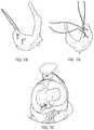
- FIGS. 1A, 1B and 2illustrate the anatomy of the meniscus in the context of a knee joint.
- the capsule region(the outer edge region of the meniscus) is vascularized. Blood enters the meniscus from the menisculocapsular region 211 lateral to the meniscus.
- a typical meniscushas a flattened bottom (inferior surface or side) and a concave top (superior surface or side), and the outer cross-sectional shape is somewhat triangular.
- the outer edge of the meniscustransitions into the capsule.
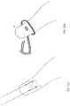
- FIG. 3illustrates the various fibers forming a meniscus. As illustrated in FIG.
- circumferential fibersthere are circumferential fibers extending along the curved length of the meniscus, as well as radial fibers, and more randomly distributed mesh network fibers. Because of the relative orientations and structures of these fibers, and the predominance of circumferential fibers, it may be beneficial to repair the meniscus by suturing radially (vertically) rather than longitudinally or horizontally, depending on the type of repair being performed.
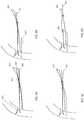
- FIGS. 4A-4Fillustrate various tear patterns or injuries to a meniscus. Tears may be vertical/longitudinal ( FIG. 4A ), oblique ( FIG. 4B ), degenerative ( FIG. 4C ), including radially degenerative, transverse or radial ( FIG. 4D ) and horizontal ( FIG. 4E ).
- Most prior art devices for suturing or repairing the meniscusare only capable of reliably repairing vertical/longitudinal tears. Such devices are not typically useful for repairing radial or horizontal tears.
- prior art device mechanismshave a high inherent risk for iatrogenic injury to surrounding neurovascular structures and chondral surfaces.
- the present inventionrelates to devices, systems and methods for suturing tissue, including a torn meniscus.
- methods for repairing tissue using a suture passer to form a locking loop suture pattern to repair the tissueare described herein.
- described hereinare methods of arthroscopically repairing difficult to access tissues such as the meniscus (including a torn meniscal root), the ACL and the rotator cuff by forming one or more locking loops of suture.
- the suture passers described hereinmay be configured so that a tissue penetrating element (tissue penetrator, needle, etc.) is configured to travel in an approximately sigmoidal pathway when passing a suture.
- a tissue penetrating elementtissue penetrator, needle, etc.
- the suture passermay be configured so that the tissue penetrator extends first distally within a first jaw member of the suture passer, then deflects from this distal direction to travel nearly perpendicular to the distal direction and across the mouth of the suture passer (and through a tissue held in the mouth of the suture passer); the tissue penetrator is then deflected to continue to extend distally within a second jaw member and eventually extend out of a distal opening in the second jaw member.
- the suture passers described hereinmay readily access and be positioned around tissue to be sutured in ways not possible with more traditional suture passers.
- these suture passersmay be positioned within the tissue by adjusting the angle of the first jaw member to help avoid non-target tissue as the device is advanced so that the first jaw member is adjacent to the target tissue.
- the second jaw membermay then be extended distally from the proximal position (e.g., by sliding axially, by swinging distally, etc.) so that the tissue is held between the first and second jaw members in a distal-facing jaw opening.
- the tissue to be suturedmay then be clamped securely between the first and second jaw members (e.g., by adjusting the angle of the first jaw member), and a loop (e.g., “bight”) of suture may be passed between the two by extending a tissue penetrator from within one of the first or second jaw members, across the opening and through the tissue, to either drop off or pick up a suture at the opposite jaw member.
- the tissue penetratorcan then be retracted back into the jaw member that houses it.
- Knee tissuemay be the meniscus (e.g., a torn meniscus, the root of the meniscus, etc.), a knee ligament (e.g., the ACL, etc.) or the like.
- Non-knee tissuesmay also be repaired as described herein.
- the methodmay include: arthroscopically passing a first loop of the loop region of the suture through the tissue with a suture passer, from a first side of the tissue to a second side of the tissue; moving the distal limb region of the suture from the first side of the tissue to the second side of the tissue; moving the distal limb region though the first loop; and cinching the first loop region closed.
- the methodmay also include forming a passage through bone to anchor the distal and/or proximal end regions of the suture.
- the methodmay include forming a passage through either the tibia or the femur; and pulling the first and second limb regions through the passage after cinching the first loop region closed.
- the tissuemay be meniscus.
- arthroscopically passing the first loopmay comprise passing the first loop of the loop region of the suture from an inferior to a superior surface of a meniscus with the suture passer.
- the tissueis anterior cruciate ligament (ACL).
- arthroscopically passing the first loopmay comprise passing the first loop of the loop region of the suture from a first side of an anterior cruciate ligament to a second side of the anterior cruciate ligament.
- the proceduremay include positioning the suture passer device around the target tissue as described in greater detail below, including any of the associated steps relevant to this positioning.
- the methodmay include arthroscopically positioning the suture passer with a first jaw on one side of the tissue and a second jaw on an opposite side of the tissue.
- the distal and proximal limbsmay be passed through the tissue, like the loop region, using the suture passer.
- the proximal or distal limb region of the suturemay be moved from one region of the tissue to another by passing the distal limb region of the suture with the suture passer through the tissue.
- the distal ends of the suturemay be moved without passing through the tissue, e.g., around the tissue.
- a methodmay also include moving the proximal limb region of the suture from the first side of the tissue to the second side of the tissue; the method may also include moving the proximal limb region though the first loop.
- Arthroscopically passing the first loopmay be performed before moving the distal limb region of the suture from the first side of the tissue to the second side of the tissue.
- a method of arthroscopically repairing a knee tissue with a length of suture having a distal limb region, a proximal limb region and a central loop region there betweenmay include: passing a first loop of the loop region of the suture from an inferior to a superior surface of a meniscus with a suture passer; passing the distal limb region of the suture from the inferior to the superior surface of the meniscus with the suture passer; passing the distal limb region though the first loop; and cinching the first loop region closed.
- the methodsmay also include passing the proximal limb region of the suture from the inferior to the superior surface of the meniscus with the suture passer, and/or passing the proximal limb region though the first loop. Passing the first loop may be performed before passing the distal limb region of the suture from the inferior to the superior surface of the meniscus with the suture passer.
- Passing the distal limb region of the suture from the inferior to the superior surface of the meniscus with the suture passermay be performed before passing the first loop.
- the methodsmay be performed primarily or entirely arthroscopically, including arthroscopically positioning the suture passer with a first jaw between the superior surface of the meniscus and the femur and a second jaw between the inferior surface and the tibia.
- a method of arthroscopically repairing a knee tissue with a length of suture having a distal limb region, a proximal limb region and a central loop region there betweenmay include: passing a first loop of the loop region of the suture from an inferior to a superior surface of a meniscus with a suture passer; passing the proximal limb region of the suture from the inferior to the superior surface of the meniscus with the suture passer; passing the distal limb region of the suture from the inferior to the superior surface of the meniscus with the suture passer; passing the distal limb region though the first loop; and cinching the first loop region closed.
- any of these methods for repairing the meniscusmay include anchoring the distal limb region and the proximal limb region to the tibia, including securing to a channel or anchoring.
- the methodmay include forming a channel in the tibia to anchor the suture.
- Any of the methodsmay include passing a second loop of the loop region of the suture from an inferior to a superior surface of the meniscus with the suture passer; and passing the proximal limb region through the second loop; and cinching the second loop region closed.
- ACLAnterior Cruciate Ligament
- FIGS. 1A and 1Billustrate the anatomy of the meniscus of the knee.
- FIG. 2illustrates the anatomy of the meniscus, including the capsule and associated vascular tissue.
- FIG. 3illustrates the structure of a meniscus.
- FIGS. 4A-4Fillustrate various tear patterns that may be repaired as described herein.
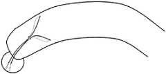
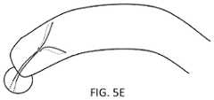
- FIGS. 5A-5Eshow one variation of meniscal root repair using a double locking loop stitch.
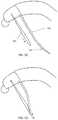
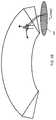
- FIGS. 6A-6Eshow another variation of a meniscal root repair.
- FIGS. 7A-7Cillustrate a meniscus repaired by a method similar to that shown in FIGS. 5A-5E and 6A-6E .
- FIGS. 8A-8Jillustrate one variation of a method to repair radial tears in a meniscus using a locking loop suture pattern as described herein.
- FIGS. 9A-9Billustrate the superior and inferior sides of an exemplary meniscus, sutured as shown in FIGS. 8A-8J .
- FIGS. 9C-9Jillustrate another variation of a method for repair of knee tissue (e.g., radio tears in the meniscus of the knee) using a pair of locking loop structures.
- knee tissuee.g., radio tears in the meniscus of the knee
- FIGS. 10A-10Hillustrate one variation of a method to repair a torn rotator cuff using a locking loop suture pattern formed by a suture passer.
- FIGS. 11A-11E and 12A-12Cillustrate variations of locking loops used as part of an ACL repair.
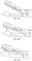
- FIG. 13shows one variation of a dual deployment suture passer as described herein.
- FIGS. 14A-14Dillustrate actuation of the first jaw member, second jaw member and tissue penetrator for one variation of a suture passer.
- FIG. 15is a side view of the suture passer shown in FIG. 13 .
- FIG. 16is a front perspective view of the suture passer shown in FIG. 15 in which the first jaw member is positioned at an angle relative to the longitudinal axis of the elongate body of the device, and the second jaw member is extended fully distally relative to the elongate body to form a distal-facing jaw opening.
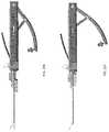
- FIG. 17Ais a side perspective view of the suture passer variation shown in FIG. 16 with the second jaw member retracted proximally.
- FIG. 17Bshows the suture passer of FIG. 17A with the second jaw extended distally
- FIG. 17Cshows FIG. 17B with the outer region of the elongate body removed.
- FIG. 18Ashows a top perspective view of the suture passer shown in FIG. 17A .
- FIG. 18Bshows a bottom perspective view of the suture passer of FIG. 17B .
- FIG. 18Cshows a bottom perspective view of the suture passer of FIG. 17C .
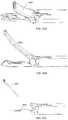
- FIG. 19Ashows a side view of one variation of a tissue penetrator.
- FIG. 19Bshows a side perspective view of the tissue penetrator of FIG. 19A .
- FIG. 20shows the perspective view of FIG. 16 with a tissue penetrator partially extended between the first and second jaw members, and with a suture loaded in the first jaw member.
- FIGS. 21A-21Cillustrate actuation of a suture passer such as the one shown in FIG. 20 to pass a suture from the upper jaw to the lower jaw.
- FIG. 22Ashows a side view of one variation of the distal end region of a suture passer, showing a first and second jaw member extended in to form a distal facing opening.
- FIG. 22Bshows another variation of the distal end region of a suture passer with the first and second jaw member extended in to form a distal facing opening.
- FIG. 23Ashows one variation of a proximal handle with controls for controlling action of a dual deployment suture passer.
- FIG. 23Bshows another variation of a proximal handle with controls for controlling action of a dual deployment suture passer.
- FIGS. 24A-24Cshow another variation of a suture passer as described.
- FIGS. 25A-25Fillustrate operation of one variation of dual deployment suture passer.
- FIGS. 26A-26Cillustrate another variation of a dual deployment suture passer configured so that the distal end of the tissue penetrator extends distally from the first jaw.
- FIGS. 27A-27Cillustrate a generic variation of a suture passer including a tissue penetrator traveling in a sigmoidal path in which the distal end of the tissue penetrator extends distally from the upper jaw.
- FIG. 28Ais another variation of a suture passer having a tissue penetrator that extends distally from the upper jaw;
- FIG. 28Billustrates the motion of the upper and lower jaw of the suture passer of FIG. 28A .
- FIG. 28Cis another variation of a suture passer having a tissue penetrator that extends distally from the upper jaw;
- FIG. 28Dillustrates the motion of the upper jaw of the suture passer of FIG. 28C .
- FIG. 28Eis another variation of a suture passer having a tissue penetrator that extends distally from the upper jaw;
- FIG. 28Fillustrates the motion of the lower jaw of the suture passer of FIG. 28A .
- FIG. 29Aillustrates different paths for a tissue penetrator in a suture passer having an upper jaw member that pivots.
- FIGS. 29B-29Eillustrate sigmoidal paths that may be taken by a tissue penetrator as described herein.
- FIGS. 30A and 30Bshow top and side views, respectively of one variation of a tissue penetrator.
- FIGS. 31A-31Eillustrate operation of one variation of a suture passer having a tissue penetrator that extends distally from the upper jaw and travels in a sigmoidal path.
- FIGS. 32A and 32Bshow side perspective views of one variation of an upper jaw member for a suture passer such as the suture passer shown in FIG. 31A .
- FIGS. 33A and 33Bshow side perspective views of another variation of an upper jaw member for a suture passer including a suture stripper.
- FIGS. 34A-34Cshow another variation of a suture passer.
- FIGS. 35A, 35B, and 35Dshow top and two side perspective views, respectively of the distal end of the suture passer shown in FIG. 34A .
- FIG. 35Cillustrates the arrangement of the tissue penetrator and suture stripper in the distal end region of the suture passer of FIG. 34A .
- FIGS. 36A-36Cshow a suture stripper including a stripper plate ( FIG. 36B ) and base ( FIG. 36C ).
- FIGS. 37A and 37Bshow side perspective views of the distal end region of a jaw member including a suture stripper.
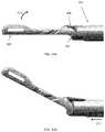
- FIGS. 38A and 38Billustrate another example of a suture that may be formed arthroscopically (“hay bale stitch”) to repair a torn meniscus having a horizontal cleavage tear.
- FIG. 38Ashows a side sectional view and
- FIG. 38Bshows a top perspective view.
- FIGS. 39A and 39Billustrate another example of a suture that may be formed arthroscopically (“cleavage stitch”) to repair a torn meniscus having a horizontal cleavage tear.
- FIG. 39Ashows a side sectional view and
- FIG. 39Bshows a top perspective view.
- FIG. 39Cillustrate another example of a cleavage suture, similar to the one shown in FIG. 39A , above, that may be formed arthroscopically to repair a torn meniscus having a horizontal cleavage tear.
- a locking loop of sutureis a loop of suture that is passed through a tissue from a first side to a second side of the tissue; one or more of the legs extending from the second side of the tissue are then passed through the loop of tissue eon the first side of the tissue, and cinched to tighten the loop closed over the one or more legs.
- one or both legsmay be passed through the tissue (e.g., an adjacent region of the tissue) so that one or both legs of the loop of suture also extend from the first side of the tissue near the loop, before they are passed through the loop and locked down by tightening the loop.
- the loopmay be tightened by pulling on the one or more legs to cinch it closed.
- these methodsmay be performed by a single suture passer such as the suture passers described herein which are adapted for passing a loop of suture through tissue, using the pair of distal-facing jaws in which one or the jaws may bend relative to the long axis of the suture passer, while the other jaw may slide proximally-to-distally in the direction of the long axis, and the suture passer (needle) can push or pull the loop of suture between this distal opening by being deflected from out of one of the jaws to extend across the distal opening, and then (in some variations) being deflected a second time to extend distally from the opposite jaw member.
- the methods of using a suture passer to for a locking loop of suturemay be used for meniscal root repair. It is well-known in the art that repair of the meniscal root is both desirable and highly difficult. For any patient, even “ideal” young and highly active candidates, meniscal repair continues to represent a significant challenge. It is undisputed that vertical tears greater than 1 cm in the peripheral-third of the meniscus should be repaired, however, there has been new attention on repairing posterior root tears. With these root tear repairs, an inside-out repair is not feasible due to the posterior midline placement of the needles and the passage of the suture.
- Both the medial and lateral meniscihave a stout attachment at their very posterior aspects, which is called the root attachment.
- the root of the meniscusis the region where the meniscus attaches to the central tibial plateau. This root attachment is important because it holds the meniscus in place, provides stability to the circumferential hoop fibers of the meniscus, and prevents meniscal extrusion.
- a tear of the meniscal rootit has been demonstrated on biomechanical testing that it is equivalent to having the whole meniscus removed. Thus, a tear of the meniscal root is considered a very serious condition.
- An example of a meniscal root repairis shown in FIG. 4F .
- Meniscal tears within the body of the meniscus or at the meniscocapsular junctionrepresent a well-understood and manageable condition encountered in clinical practice.
- meniscal root tearsMRTs
- MRTsmeniscal root tears
- the root attachments of the posterior horns of the medial and lateral meniscusare very important for joint health. When these are torn, the loading of the joint is equivalent to having no meniscus on the affected side.
- these patientscan often have early onset arthritis, the development of bony edema, insufficiency fractures, and the failure of concurrent cruciate ligament reconstruction grafts. For this reason, much research has gone in to meniscal root repairs over the last several years.
- meniscal repair techniquesthat suture the meniscus from the “outside” (e.g., though the capsule) may not properly restore the anatomy, for example, anchoring the meniscus to the posterior capsule, rather than the tibia.
- FIGS. 5A-5E and 6A-6FA superior method of repairing a meniscal root is described below and two variations are illustrated in FIGS. 5A-5E and 6A-6F
- FIGS. 5A-5Eshow one variation of meniscal root repair using a double locking loop stitch.
- the root of the meniscusmay be arthroscopically repaired using any of the suture passers capable of minimally invasively (e.g., arthroscopically) and being positioned on both the superior and inferior sides of the meniscus and passing a suture between the superior and inferior sides. Examples of these suture passers are described below.
- the legs of a loop of sutureare each passed between the superior and inferior sides (e.g., from the inferior to the superior side) and then the middle region between the two is passed to form a loop on the superior side.
- the legs of the suturethus extend from the superior side in two different locations (e.g., radially and/or longitudinally spaced locations) and are pulled though the loop on the superior surface side then the loop is cinched (e.g., by pulling on one or both legs) to tighten it over the legs.
- the legsmay then be secured to the tibia (e.g., into a tibial tunnel).
- the legsmay be passed after the loop (the region of the suture length between the legs) is passed, or the first (e.g., distal) leg may be passed, then the loop (the region of the suture length proximal to the first leg) then the second (e.g., proximal) leg may be passed.
- the order in which the two legs and the loop region between them are passed between the first and second sides of the tissuemay be varied in any of the methods described herein, unless otherwise specified.
- the suture passermay pass a distal “bight” (or loop) of suture by pushing or pulling it through the meniscus once the distal-facing mouth formed by the two jaws of the suture passer have been positioned (e.g., arthroscopically) around the meniscus.
- the suture passermay arthroscopically access the meniscus of the knee with a first jaw retracted proximally (relative to the proximal-to-distal long axis of the shaft of the device); the second jaw may be bent or bendable (e.g., pivotable) at the distal end region of the shaft of the device.
- the second jawmay be positioned adjacent to the superior surface either before or concurrently with sliding the first jaw distally to extend it relative to the elongate shaft so that it is extended adjacent to the inferior surface of the meniscus, positioning the meniscus between the distal-facing jaws.
- the tissue penetratore.g., needle
- the tissue penetratormay then push or pull the distal end region of the suture length through meniscus, e.g., from the inferior to the superior surface. If the suture is passed as a loop (e.g., bight) of suture, the distal most end of the suture may be drawn through the tissue until just a single-stranded length of the suture (corresponding to the first leg) passes through the tissue.
- the second leg (e.g., the proximal end region) of the suturehas been passed through a radially offset region of the meniscus from the inferior to the superior side as shown in FIG. 5B .
- the proximal end region or length 507 of suturemay be loaded on to the suture passer (or it may have been pre-loaded onto the suture passer) and it is extended (e.g., as a bight or loop) though the meniscus from the inferior to the superior surface.
- the proximal endextended completely out of the meniscus so that both the first leg (the distal length of the suture) and the second leg (the proximal length of the suture) extend out of the superior side.
- the region between the first and second legs, the middle region,is located on the inferior side and may extend out of the patient, e.g., the access port for arthroscopically accessing the tissue.
- This central regionmay then be passed (as a loop or bight) by the same suture passer from the inferior to the superior surface of the meniscus, so that a loop 509 of the central region of the length of suture also extends from the superior surface of the meniscus, as shown in FIG. 5C .
- the loopmay be passed in a radially intermediate region (between the first and second legs) transversely though the meniscus, as shown.
- the passage through the meniscus of the loop (and any of the legs)may also be laterally offset relative to the legs.
- the first and second legs of the suturemay be passed through the loop on the superior surface, as shown in FIG. 5D .
- Thismay be performed after withdrawing the suture passer, e.g., by a suture grasping instrument, hook, etc.
- the loopmay then be cinched down over the legs of the suture, as illustrated in FIG. 5E , and the legs secured to the tibia. This may be done concurrently or separately.
- the loopmay be cinched down, and the resulting double locking loop stitch may hold the end of the meniscus so that it can both be repositioned and secured relative to the tibial plateau. Additional sutures (including additional locking loop stitches) may be used.
- FIGS. 6A-6EAnother variation of a meniscal root repair is shown in FIGS. 6A-6E .
- the perspective viewshows the top/superior surface of the meniscus as well as the bottom/inferior surface of the meniscus.
- An access region through the tibiahas been formed (tunnel 605 ) that may be used to secure the meniscus to the tibial plateau after forming the appropriate locking loop.
- a suture passerthat is configured so that it can arthroscopically be positioned with a first jaw adjacent the superior surface and a second jaw adjacent the inferior surface and pass a length of suture between the superior and inferior surface may be used, and positioned as described above.
- the middle region of the length of suture to form the locking loopis passed first, as shown in FIG. 6B .
- the suture passeris not illustrated, but it operated as described below.
- a loop of the middle region 609extends from the superior surface as shown.
- the suture lengthincludes a distal region that will form a first leg and a proximal region that will form a second leg and a central region between the two forming the loop.
- the distal and proximal lengthsremain outside of the subject, e.g., extending from the arthroscopic access port in the knee used by the suture passer.
- the suture passermay be configured so that it releases the loop on the inferior side, allowing it to be repositioned to pass the first and second legs, while leaving the loop on the superior surface.
- the first (e.g., distal) leg of the length of suturehas been passed through the meniscus from the inferior to superior side, so that it extends from the superior side.
- the lengthmay be longer.
- the figuredoes not show the adjacent bone regions (e.g., femur head and tibial plateau) that constrain the access to the meniscus, however, however they are typically present.
- the free ends of the first and second legare shown extending away from the meniscus for convenience, in practice, they may be positioned between the superior surface of the meniscus and the femur head.
- FIG. 6Dshows the second leg after it has been passed by the suture passer from the inferior to the superior side of the meniscus.
- FIG. 6Ethe ends of the first and second leg have been pulled through the loop and into the tibial tunnel 605 , so that they can be used to cinch the loop and secured to hold the meniscus in place. Additional sutures (including additional locking loops) may be used.
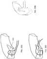
- FIGS. 7A and 7Billustrate the inferior and superior sides of a meniscus that has been removed from the body after forming two locking loops as discussed above. The resulting stitches have a chevron-like pattern on the superior and inferior surfaces of the meniscus.
- FIG. 7Cshows a model of the knee, with the femur removed, in which a meniscal root has been repaired by this method.
- the method of forming a locking loop of suturemay also be used to repair other tears and regions of the meniscus, including, but not limited to radial tears. This is illustrated in FIGS. 8A-J .
- two locking loop suturesare used, one securing each side of the tear 801 , and then the two may be connected or bridged to pull the sides together.
- Having a loop of suture on each side of the tearmay provide additional strength to hold the sides of the tear in apposition without placing too much strain on the side regions of the meniscus, forming a very strong suture.
- FIG. 8Athe radial tear 801 is shown.
- a percutaneous access port 802is used to access the knee and the “inside” of the central region between the meniscuses.
- the same suture passer described abovemay be used.
- This locking loop suture patternmay be formed by a suture passer that can be positioned arthroscopically in the knee so that a first jaw is positioned between the superior surfaced and the femur head, a second jaw if positioned between the inferior surface and the tibial plateau, and a tissue penetrator can push or pull a suture bight between the superior and inferior surfaces. Examples of such suture passers are provided below.
- such a suture passerhas been used to pass a loop of suture 803 from the inferior to the superior side of the meniscus and back out of the knee, as shown.
- the first 805 and second 807 legsalso extend from the knee.
- the first leghas been passed (using the same suture passer, e.g., by reloading with the first leg length of suture) from the inferior to the superior side of the meniscus, and the first leg is drawn back out of the knee, as shown in FIG. 8C .
- the first leg 805may then be passed through the loop 803 .
- the loopmay then be cinched, by pulling the first leg, as shown in FIGS. 8D and 8E .
- a loop 809 formed of the second leg or length of suturemay be passed, using the suture passer, through the meniscus on the opposite side of the tear from the inferior to the superior side, as shown in FIG. 8F .
- This loopmay be formed of a region intermediate between the cinched loop 805 and the distal end of the second leg 807 .
- the second legmay then be loaded on to the suture passer and passed from the inferior to the superior side, and withdrawn from the knee, as shown in FIG. 8G .
- the method illustrated aboveinclude the steps of removing the passed suture lengths (loop, first and second leg) out of the knee, this is not necessary, though it may be helpful for managing the many lengths and loops of suture.
- FIG. 8Hthe proximal end of the second leg 807 of suture is then passed through the second loop 809 , and the second loop is cinched by pulling on the second leg, as shown in FIG. 8 i , leaving the first and second legs extending out from the superior side of the meniscus. These ends may then be knotted, and the knot tightened to bring the torn sides of the meniscus in apposition and secured together, as illustrated in FIG. 8J .
- FIGS. 9A and 9Billustrate the superior and inferior sides of an exemplary meniscus, sutured as described above.
- FIGS. 9C to 9Jillustrate another method of using a pair of loops formed in a single loop region of a length of meniscus to repair a radial tear in the meniscus.
- Any of the suture passers described and incorporated by reference hereinmay be used to (e.g., arthroscopically) repair the torn meniscus as illustrated.
- a single suturethat includes a central loop region between a proximal leg region and a distal leg region (e.g., proximal end region and distal end region) is used to initially pass a first loop 901 on one side of the radial tear and a second loop 903 on the opposite side of the radial tear.
- a suture passer pre-loaded with suturemay be used to pass the first loop (length) from the inferior to the superior side of the meniscus, so that the loop project from the superior side, as shown in FIG. 9C .
- the distal and proximal end regions of the suturemay then be passed lateral to the loops, as shown in FIG. 9D .
- the suture passermay be re-loaded with the proximal end/leg region 905 and passed, e.g., initially as a loop, so that the proximal end of the suture can be completely pulled through the tissue so that the proximal end is on the superior side of the meniscus as shown; this procedure may then be repeated with the distal end/leg of the suture 907 on the opposite side of the tear, lateral (and slightly radially) offset from the second loop, as shown.
- the proximal and distal ends of the suturemay then be pulled through the first and second loops, respectively. These ends may then be pulled to cinch the loops and pull the tissue together, as shown in FIG. 9F .
- the proximal and distal legsmaybe tied together over the superior surface of the meniscus, across the radial tear, as shown in FIG. 9G .
- the endsmay be cut, as illustrated in FIG. 9H . This procedure may then be repeated across a second, radially offset, region of the radial tear, as summarized in FIGS. 9I and 9J .
- only a single length of suturee.g., stopping at the step shown in FIG. 9H
- additional length of suture(not shown) may be used.
- FIGS. 38A-38Billustrate a “hay bale” stich that may be used to repair a torn meniscus, and in particular a meniscus that has a horizontal cleavage tear 3800 .
- the meniscusIn a horizontal cleavage tear, the meniscus is divided up into two layers, an inferior (“bottom”) region and a superior (“upper”) region. The inferior portion extends radially further than the superior region because of the angle of the superior surface.
- a single length of sutureis passed through the meniscus a single time through both the inferior and superior regions, as shown in the sectional view of FIG. 38A .
- the suturemay then be cinched so that the resulting loop of suture passes has a single length of suture that passes through the meniscus and the rest of the loop extends outside, around the apex of the meniscus.
- the un-tied loopis shown in FIG. 38B .
- the suture passersuch as the ones described herein may be positioned with a lower jaw adjacent to the inferior surface and the upper jaw adjacent to the superior surface, and the suture may be passed (e.g., from the bottom to the top or from the top to the bottom) between the superior and inferior surfaces, then one end of the suture pulled out so that both ends of the suture length may be knotted together to form the complete loop.
- FIGS. 39A, 39B and 39CAnother variation of a suture that may be used to repair a horizontal cleavage tear is shown in FIGS. 39A, 39B and 39C .
- the meniscusincludes a horizontal cleavage tear 3900 that is repaired by forming a loop of suture in which two portions are passed through the inferior portion of the meniscus (the lower portion) formed by the tear and a single portion of the suture loop passes through the superior portion (upper) of the meniscus.
- the stitch shown in FIG. 39Amay be knotted, e.g., with a knot pusher, by knotting the two ends of the suture together for form the complete loop.
- FIG. 39Bshows a top view of this stitch (unknotted). This stitch may be referred to as a cleavage stitch.
- the stitch shown in FIGS. 39A and 39Bmay be formed by passing a first bight (e.g., loop) of suture from the inferior surface, e.g., by positioning the lower jaw against the inferior surface and the upper jaw against the superior surface) to the superior surface, then pulling the distal end of the suture all the way through, leaving the suture spanning the thickness of both the inferior and superior regions through the horizontal cleavage tear.
- the distal end of the suture(exiting the superior side of the meniscus) may then be passed from the superior side just through the inferior portion, and pulled through the inferior side, so that both ends of the suture extend from the inferior side of the meniscus, as shown in FIGS. 39A and 39B .
- a suture passer that passes from a lower jaw to an upper jawmay be used to pass the first length of suture from the inferior to the superior side, and then the suture passer may be flipped over and used to pass the distal end of the suture extending from the superior side through the inferior portion (only) of the torn meniscus.
- the free ends of the sutureextend from the inferior side and may be knotted so that the knot is on the inferior side.
- FIG. 39Cshows another example of a cleavage stitch in which the suture is passed from the inferior to the superior surface of the meniscus, through the horizontal cleavage tear, and the proximal end of the suture is then re-loaded and passed from the inferior to the superior surface to form the stitch shown in FIG. 39C .
- this stitchmay then be completed by knotting the two ends (proximal and distal) of the suture to form a loop in which the inferior portion has two lengths of suture passing through it while the superior portion has only a single length of suture.
- the knotmay be formed on the superior side of the meniscus.
- a method of forming a locking loop of suture as described hereinmay also be used to repair the rotator cuff.
- the basic premise of repairing tissues such as the ACL and the rotator cuff using a suture passer to form the suture patterns (e.g., locking loop, double locking loop) described hereinis same.
- a central portion of a length of sutureis arthroscopically passed through a tissue, and then one or both terminal ends (arms, limbs, etc.) is arthroscopically passed through and/or around the tissue and through the previously passed loop, and the loop is cinched down.
- a locking suture patternthrough a tissue by: passing a non-terminal portion of the length of suture through the tissue, passing a terminal portion of the suture through a different location on the tissue, and passing the terminal portion of the suture through the loop so that a locking pattern is achieved.
- FIGS. 10B-10 iillustrate rotator one method of repairing a torn rotator cuff using a suture passer to form a locking loop, in conjunction with a suture anchor.
- FIG. 10Ashows an intact shoulder region in which the supraspinatus is attached to the humeral head.
- FIG. 10Bthis tendon is shown torn from the humeral head.
- the suture passers described hereinmay be used to repair the tissue arthroscopically by passing the suture to form a locking loop, even despite the space restrictions of the shoulder region.
- FIG. 10Ashows an intact shoulder region in
- an anchorhas been secured to the humeral head; in practice, the anchor may be attached before or after the tendon has been sutured, so that it may be connected by the suture to the anchor and therefore the humeral head.
- a suture anchorhas been secured to the humeral head and a length of suture is attached. This length of suture may be used to form the locked look by the suture passer.
- the suture passercan be loaded with the pre-attached suture to pass the suture through the tendon, as shown in FIG. 10D .
- a distal end of the suture extending from the anchoris passed through the torn tendon from a first side of the tendon to a second side of the tendon.
- the same suture passermay be used to pass a loop region of the same suture (proximal to this distal end region) through in the same direction, from the first side to the second side of the tendon.
- the free distal end of the suturemay then be passed through the loop, and the loop may be “locked” by drawing on the distal end of the suture to cinch the loop closed, as shown in FIGS. 10F and 10G .
- the locked loopmay then be secured (e.g., tied) to the anchor, as shown in FIG. 10H .
- the free end of the locked loopmay be tied off to the free end of the anchor, pulling the tendon in position and securing it to the humeral head, as illustrated.
- the loose ends of suturemay then be removed.
- the locking or locked loop formedmay be freely cinchable; the loop is locked relative to the tissue, so that it does not pull out or come off of the tissue. However, the portions of the suture forming the locking loop may slide relative to each other.
- any appropriate anchormay be used with any of the method described herein when suturing tissue with a locking loop as described.
- a knotless anchormay be used, or a traditional anchor.
- FIGS. 10C-10Hillustrate a traditional anchor, where only one end if the suture is passed (the other end may be used to tension the repair to the bone).
- FIGS. 11A-12Cillustrate variations of locking loops used as part of an ACL repair.
- a dual locking loophas been passed through the torn end region of the ligament.
- Both legs and a loop region of the suturehave been passed forming a triangle between the two, with the two leg regions passed through the loop before cinching it down, similar to the dual locking loop illustrated above in FIGS. 5A-6E .
- FIG. 11Bis another example of a method of repairing the ACL in which to separated locking loops have been passed; both sets of free suture legs may be secured to the femoral head in this example.
- FIG. 11Cillustrates another variation of a suture that may be formed with the suture passers described herein, having an extremely low delivery profile, yet able to be attached around the target (e.g., ACL) tissue.
- the targete.g., ACL
- FIGS. 11D and 11Eshow other variations of locking loop patterns that may be used.
- FIGS. 12A-12Cillustrate another variation of a locking loop suture pattern in which a central loop of suture (as shown in FIG. 12A ) is first passed through the ACL, and the legs of the suture (first and second legs) are wrapped around the tissue (in FIG. 12B ) before being passed through the loop and drawn to tighten the loop as shown in FIG. 12C .
- multiple loops of the length of suturemay be passed, and one or both proximal and distal ends (distal leg region/proximal leg regions) may be passed through these loops to form more complex locking patterns, as suggested by FIG. 11E .
- the suture passers described hereinmay be used as a low-profile suture passer that can be arthroscopically inserted into a very tight (e.g., congested) region and positioned around a target tissue to pass a suture from one side of the tissue to another side, as illustrated above.
- the suture passer devices described hereinmay be referred to as suture passers and/or suturing devices.
- Different variations of the devices described hereinmay also be referred to as snake-tongue, sigmoidal, dual deployment suture passers, and/or clamping/sliding suture passers.
- the suture passers described hereininclude a first jaw member and second jaw member that extend from the end of an elongate body region to form a distal-facing mouth into which tissue to be sutured fits.
- one or both jaws forming the mouthmay be independently moved.
- FIG. 13illustrates one variation of a dual deployment suture passer 100 .
- the devicehas a first (upper) jaw member 103 extending distally from the distal end of a more proximal elongate member 101 .
- a second jaw member 105is shown extended distally beneath the first jaw member 103 .
- a handle 107is located at the proximal end of the device and includes multiple controls for independently controlling the movements of the first jaw member, second jaw member, and tissue penetrator.
- the handle in this examplealso includes a second jaw member lock for locking/unlocking the movement of the second jaw member.
- the suture passer shown in FIG. 13is positioned with the first jaw member held at an angle relative to the long axis of the proximal elongate member.
- the first jaw member in this exampleis shown having a hinge region 113 about which the first jaw member may be angled relative to the elongate member.
- this hinge regionis a pinned hinge; non-pinned (e.g., living hinges) regions may be used. Any appropriate articulating region that allows the first jaw member to move at an angle relative to the proximal portion of the device (e.g., the elongate member) may be used.
- this first jaw memberis referred to as an upper jaw member, but alternative variations (in which the first jaw member is a lower jaw member) are also possible.
- the first jaw membermay be actuated by any appropriate mechanism, including a tendon member (e.g., push rod, pull rod, or the like), and may be held (locked) at any angle (e.g., between about 0° and 90°, between about 0° and 60°, etc.).
- a tendon membere.g., push rod, pull rod, or the like
- any anglee.g., between about 0° and 90°, between about 0° and 60°, etc.
- the devicehas a neutral position during which no force is applied to the controller to move the first jaw member, so that the first jaw member is angled “open” (e.g., at 30°, 45°, 50°, 90° or at any angle between about 15° and about 90°) relative to the elongate body; actuating the control on the handle results in the first jaw member moving towards the “closed” position (e.g., reducing the angle with respect to a line extending from the distal end of the elongate body).
- the jaw memberis in the neutral position when angled with 0°/180° relative to the elongate body.
- the first jaw member shown in FIG. 13also includes a suture retainer region near the distal end (described in greater detail below).
- This suture retainer regionmay hold the suture or be configured to hold a suture.
- the suture retainerincludes a channel or guide for holding the suture in a preferred position.
- the suture retainerincludes a pair of graspers, or deflectable members into which the suture may be pushed and held (e.g., handed off from the tissue penetrator).
- a suture retainergenerally holds the suture so that it can be either removed by the tissue penetrator, or so that a suture can be passed into the suture retainer from the tissue penetrator.
- the suture retaineris a channel across which the suture extends so that it can be reliably engaged and pulled down by the tissue penetrator as described in more detail below.
- the second jaw memberincludes a suture retainer, rather than the first jaw member.
- the second jaw memberis shown in FIG. 13 as a lower jaw member.
- the lower jaw memberis configured to slide proximally towards and into the proximal elongate body of the device.
- the second jaw membertypically moves axially, in the direction of the proximal-distal axis of the suture passer.
- the second jaw membermoves axially completely past the distal end of the elongate body; alternatively, the second jaw member slides axially in the proximal direction only partially (e.g. to align with the hinge region of the first jaw member).
- the second jaw member shown in FIG. 13retracts completely into, and extends out of, the lower portion of the elongate body.
- the second jaw membermoves axially in parallel with the lower jaw member, or only a portion of the lower jaw member extends into the elongate body.
- a tissue penetrator(not shown in FIG. 13 ) may be housed within either the first or second jaw member.
- the tissue penetratormay be configured as a needle, wire, knife, blade, or other element that is configured to extend from within either the first or second jaw members and across the opening between the jaw members to engage a suture retainer and either drop off or pick up a suture therefrom.
- the tissue penetratormay be configured to completely retract into the jaw member housing. It may be extended across the opening between the jaws by actuating a member in the handle to push or otherwise drive it across the opening, and though any tissue held between the jaws.
- the second jaw member 105 shown in FIG. 13completely houses the tissue penetrator and includes a deflection region that drives the tissue penetrator up and out of the second jaw member by deflecting it across the opening between the two.
- the elongate body 101 shown in FIG. 13is illustrated as a relatively straight cylindrical body, though other shapes may be used.
- the elongate bodymay be curved, bent, or angled.
- the elongate bodyis configured to be bent, curved or angled dynamically (e.g. by changing the bend or curve).
- the elongate bodymay be any appropriate length.
- the elongate bodymay be between about 6 and about 24 inches long, e.g., 6 inches long, 8 inches long, 10 inches long, 12 inches long, etc.
- the suture passers described hereinmay be used for arthroscopic surgeries and therefore may be dimensioned for use as such.
- the diameter of the devicemay be configured to be small enough for insertion into a cannula, tube or the like for insertion into the body.
- FIGS. 14A-14Dillustrate one variation of the distal end region of a dual deployment suture passer forming a distal-facing opening and extending a tissue penetrator across the distal opening.
- the distal end of the deviceis shown with the first jaw member 201 (shown here as an upper jaw member) extended distally at 0° relative to a line extending from the distal end of the elongate body 203 .
- This “straight” configurationmay be helpful for inserting and/or removing the distal end of the device into the tissue (e.g., through a cannula).
- the first jaw membercan then be bent, or allowed to bend in some variations, at an angle relative to a line extending from the distal end of the elongate body.
- the first jaw memberpivots around a hinge point 205 , and is controlled by a pulling member 208 that pushes and/or pulls proximally and/or distally to control the bend of the first jaw member.
- the pulling membermay include a shaft, wire, tendon, tube, cannula, or the like, and may extend to the proximal end of the device where it can be controlled.
- the arrow 211 in FIG. 14Aillustrates the plane and direction of motion of the first jaw member.
- FIG. 14Bthe first jaw member has been moved (or allowed to move) so that it forms an angle of approximately 30° with a line extending from the distal end of the elongate body.
- the arrow 215 in FIG. 14Billustrates the direction of axial motion that the lower jaw (not yet visible in FIG. 14B ) will be moved.
- FIG. 14Cillustrates the direction of axial motion that the lower jaw (not yet visible in FIG. 14B ) will be moved.
- FIG. 14Cin which the lower jaw member 207 has been extended distally from the proximal region of the device.
- the second jaw member 207is shown fully extended distally relative to the elongate body region 203 .
- this exampleshows the second jaw member extending from completely within the elongate body region (as in FIG.
- the lower jaw memberin some variations is held outside of the elongate body region, or only partially within the elongate body region. In some variations the second jaw member is completely retracted proximally so that much (or all) of the second jaw member is held proximal to the distal end of the elongate body region 203 .
- the tissue penetratormay be sent across the distal-facing opening 222 as shown in FIG. 14D .
- the distal end of the tissue penetratormay be configured to extend distally from an opening in a jaw member
- the tissue penetratormay be prevented from exiting the opposite side of the jaw member.
- the tissue penetratormay be prevented from extending distally beyond the jaw member by a limiter (e.g., a travel limiter and/or a movement limiter).
- a limitere.g., a travel limiter and/or a movement limiter
- the first jaw memberincludes a cage or shield region 232 that prevents the tip of the tissue penetrator from extending out of the first jaw member where it may cut or damage the non-target tissue.
- the devicemay also include a movement limiter, which limits the movement of the tissue penetrator so that it can only extend to just couple with the opposite jaw member (and pass or grab a suture held therein). Since the jaws may be open to varying positions, a movement limiter may help prevent the tissue penetrator from overextending even when the first jaw member is only slightly angled with respect to a line extending from the distal end of the elongate body.
- the tissue penetratormay be prevented from extending across the opening between the first and second jaw members unless the second (axial moving) jaw member is extended distally relative to the elongate body. This may allow the tissue penetrator to mate properly with the suture engagement region on the first jaw member.
- a lock or other mechanismmay be used to prevent the tissue penetrator from engaging with a control at the proximal end of the device until the second jaw member is fully extended.
- FIG. 15A side view of the device shown in FIGS. 13-14D is provided in FIG. 15 .
- FIG. 16shows a front perspective view of the distal end region of the device of FIGS. 13-15 with the second jaw member extended fully distally and the first jaw member angled slightly (e.g., approximately 30° relative to a line extending distally from the longitudinal axis of the elongate body).
- the lower jaw member 403may be configured to fit within the upper jaw member 401 when the two jaw members are closed down on one another (not shown).
- the first jaw member in this examplealso includes optional side windows 402 .
- the first jaw membermay also include a suture engagement region; in FIG.
- this suture engagement regionincludes a channel 409 through the midline (extending proximally to distally) and a first 415 and second 417 notch or protrusion cut into the first jaw member.
- a suturemay be wrapped around the first jaw member by passing from the proximal end of the device, under the proximal notch 417 and along the bottom (e.g., the side of the first jaw facing the extended second jaw) around the distal end of the first jaw member and along the top (e.g., the side of the first jaw facing away from the second jaw) and, under the distal notch 415 and back up out of the proximal notch 417 so that the suture may extend distally.
- This loop of suture held by the suture engagement region of the jaw membermay be held under sufficient tension so that the suture may be engaged by the suture engagement region of the tissue penetrator (e.g., hook, grasper, etc.).
- a tensioning membermay be included in the suture engagement region.
- the suturemay be contained within the elongate body of the device. Alternatively, the suture may be kept outside of the device. In some variations the suture may be loaded by the user. For example, a user may load a suture on the device by placing a loop of suture over the first jaw member. In some variations the suture holder may be placed along the length of the device to hold or manage the suture so that it doesn't interfere with the operation of the device or get tangled.
- FIGS. 17A-17C and 18A-18Cillustrate different views of the first and second jaw members in one variation.
- the first jaw memberis shown with the second jaw member retracted proximally.
- FIG. 18Ashows a top perspective view of the same first jaw member shown in FIG. 17A .
- the first jaw memberincludes a channel 605 extending along the longitudinal length of the first jaw member; this channel may form part of the suture engagement region. The channel may hold the suture so that it extends along the midline of the first jaw member on the underside of the first jaw member.
- the notches 607 , 609 in the first jaw member near the proximal endextend toward the midline of the first jaw member and allow the suture to pass from the top of the first jaw member to the bottom and back out, as discussed above.
- the suturemay be held close to the elongate body of the device even when the first jaw is open to various angles.
- FIG. 18Billustrates the underside or bottom of the first jaw member shown in FIG. 18A .
- the suture management regionis the entire opening formed at the distal end.
- This cavity 613is surrounded by the inside of the first jaw member, and (as mentioned above) may act as a limiter to limit the tip of the tissue penetrator from extending outside of the first jaw member.
- FIG. 18Cshows the same view as in FIG. 18B , but with the second jaw member axially extended distally.
- FIG. 17Ba side view of the distal end of one variation of a suture passer is shown with the second jaw member extended distally.
- FIG. 17Cshows the same view as in FIG. 17B but with the outer cannula covering for the elongate member removed, showing the connection between the second jaw member and the pushing/pulling element (rod 505 ).
- the pushing/pulling elementmay be a wire, shaft, tendon, or the like, allowing the second jaw member 503 to be controllably slid distally and proximally.
- the tissue penetratoris not visible in FIGS. 17A-18C.
- FIG. 19Ashows one variation of a tissue penetrator 700 as described herein.
- the tissue penetratorincludes a sharp, pointed distal tip 701 and just proximal to the distal tip is a suture engagement region configured as a hooked cut-out region 703 .
- the proximal end of the tissue penetratorincludes a coupling region for coupling the tissue penetrator with a pusher/puller mechanism, such as a shaft, rod, wire, tendon, or the like.
- FIG. 20shows the same perspective view of FIG. 16 , but with the tissue penetrator 805 partially extended across the distal-facing opening formed between the first jaw member 801 and the second jaw member 803 .
- a suture 808is looped around the first jaw member 801 . Both ends of the suture pass into the notched region and are held close to the elongate body, allowing the loop of suture to be held in tension within the suture engagement region.
- FIGS. 21A-21Cillustrate the variation of the device described above passing a suture from the first jaw member to the second jaw member.
- the distal end of the second jaw member for the dual deployment suture passerhas been extended fully.
- the upper jawis held at an angle relative to the elongate body region of the device proximal to the joint (e.g., hinge, bend region, etc.) of the first jaw member.
- a suturehas been loaded into the suture engagement region, and extends along the length of the midline of the first jaw member.
- the first jaw memberhas been moved slightly (decreasing the angle between the first jaw and the fully extended lower jaw member). This may be typical of situations in which tissue is held between the first and second jaw members.
- tissue penetratorClamping the tissue to be sutured in this manner allows the tissue to be secured within the jaws, preventing it from moving undesirably, and helping the tissue penetrator to penetrate through the tissue.
- FIG. 21Bthe tissue penetrator has been extended from the lower second jaw member across the distal-facing opening, towards the first jaw member and the suture retained therein. Once the tissue penetrator contacts the suture, it may be grabbed or otherwise engaged by the suture engagement member of the tissue penetrator. Thereafter, the suture can be pulled back down with the tissue penetrator as it retracts back into the second jaw member. In this variation, the loop of suture is pulled back through the tissue.
- FIGS. 22A and 22Billustrate two variations of the upper jaw member.
- FIG. 22Bshows a variation in which the straight jaw member of the first jaw member is instead a curved jaw member; the curve may allow a greater thickness of tissue to be placed between the jaws and may also be useful for navigating certain tissue regions, such as the labrum and ACL.
- first jaw memberin many of the variations described herein may be dynamically angled with respect to the elongate body of the device.
- the first jaw membermay be connected to and extend from the distal end of the elongate body, or may be connected to an intermediate region between the elongate body and the first jaw member.
- FIG. 23Ais an enlarged view of the handle region of the suture device discussed above in FIGS. 13-15 .
- the handleincludes a control to control the motion of the first jaw member (which may also be referred to herein as a clamp trigger), a second jaw member control 1605 (or lower jaw handle), and a tissue penetrator control 1607 (or needle trigger). Additional controls may include a lower jaw screw lock to lock the position of the lower jaw member. The operation of this handle variation in controlling a dual deployment suture passer is described below with respect to FIGS. 25A-25F .
- FIG. 23Billustrates another variation of a handle for a dual deployment suture passer.
- the handle controlsare triggers/handles.
- the proximal trigger 1705is a squeeze handle that controls the angle of the first jaw member relative to the elongate body.
- the control and handleare configured with a bias element (spring 1707 ) that tends to keep the first jaw member at an angle with respect to the elongate member; in this example, the angle is about 30° relative to a line extending distally from the long axis of the elongate body region of the device.
- a second grip control 1709controls the extension of the second (lower) jaw member (not visible in FIG. 25B ).
- a second biasing element (spring) 1711tends to hold the control so that the second jaw element is retracted proximally and, in this example, into the elongate member.
- a third trigger control 1715controls the extension of the tissue penetrator.
- This controlis arranged to include a lock that prevents the control from engaging with the tissue penetrator until the second jaw member is completely extended.
- the controlalso includes a travel limiter 1721 that limits how far the tissue penetrator may be extended from within the second jaw element based on how angled the first jaw member is, preventing the tissue penetrator from trying to extend beyond the first jaw element.
- the controlsmay be handles or triggers (as illustrated in FIGS. 23A and 23B ) or other controls, such as dials, buttons, sliders, switches, or the like.
- the suture passer devicesinclude the dual deployment suture passers described above
- the tissue penetratorlimits the travel of the tissue penetrator to prevent it from extending beyond the opposite jaw member from where it is housed when not extended
- the tissue penetratoris deflected within the opposite jaw member and allowed to extend distally out of the opposite jaw member some amount (e.g., less than 5 mm, about 5 mm, less than 4 mm, about 4 mm as shown in FIG. 26B , less than 3 mm, about 3 mm, etc.).
- the tissue penetratormay be housed in the second jaw member and may be deployed across the distal-facing opening formed when the first and second jaw members are extended fully distally.
- the tissue penetratoris shown partially extended from the second jaw member in FIG. 26A , however it should be understood that the tissue penetrator (including the tip of the tissue penetrator) may be fully retraced or retractable into the second jaw member.
- the jaw membersare shown close together, e.g., with only a little space between the first and second jaw members; the jaws may be more opened, for example, by moving the first (upper) jaw member at an angle with respect to the more proximal region of the device.
- the tissue penetrator 1622extends from within the second jaw and across the distal-facing opening to pass into an opening on the opposite (first or upper) jaw member.
- the tip of the needleis pointed in this example, and a side region of the needle proximal to the pointed distal tip is recessed to form a suture engagement region that is hook-shaped. Extending the needle into and partially out of the first jaw member as shown in FIG. 26B allows the suture engagement region on the tissue penetrator to engage the suture held by the first jaw member, as shown.
- the tissue penetrator in this exampleextends out of the distal end of the first jaw member distally (not laterally) and is limited to extending just a finite amount (e.g., less than 4 mm) from the distal tip of the first jaw member.
- a finite amounte.g., less than 4 mm
- the variation of the suture passer illustrated in FIGS. 26A-26C in which the tip of the tissue penetrator extends distallyhas various features or advantages including simplifying the coordination between the various parts. For example, less coordination is required to limit the needle motion (e.g., stopping it before it crashes into the first or upper jaw). This may allow greater tolerances, and the parts may require less precision. Also, extending the tissue penetrator distally may allow for “over travel” of the tissue penetrator and provide for more reliable engagement (hooking) of the suture by the suture engagement region.
- the distal end of the first jaw membermay include sufficient space for the tissue penetrator to over-travel the suture so that the hook (suture engagement feature) on the tissue penetrator can grab the suture on its way back to the lower (second) jaw member.
- the height of the first jaw membercan be compressed sizably, and the over-travel necessary to pick up the suture is directed in a manner that doesn't require additional height.
- the additional over-travel opportunity offered by this configurationmay allow use of a symmetric distal tip region for the suture penetrator, e.g., having a point in the middle of the tissue penetrator distal tip region.
- Asymmetric tissue penetratorsmay also be used (e.g., having a point on one side of the tissue penetrator).
- Other examples of suture passers (including dual deployment suture passers) having tissue penetrators configured to extend beyond the distal end of a jaw memberare described and illustrated below, including in FIGS. 27A to 37B .
- FIGS. 24A-24Cillustrate another variation of a suture passer.
- the second jaw memberis not retracted proximally, and the first and second jaw members are clamped together.
- the first jaw membermay be opened as shown in FIG. 24B , and the tissue penetrator may be extended across the distal-facing opening, as shown in FIG. 24C .
- the suture passer devices described hereinmay be used to suture any appropriate tissue. These devices are particularly well suited for passing a suture in a minimally invasive procedure to reach difficult to access regions. Examples of the use of these devices are provided below, and illustrated in FIGS. 25A to 25F .
- FIGS. 25A-25FThe general operation of one variation of a dual deployment suture passer is illustrated in FIGS. 25A-25F .
- the clamping/sliding suture passer illustrated in FIG. 25Aincludes a handle such as the one shown in FIG. 23A , above.
- a suturemay be loaded on the first jaw member of the device.
- a loop of suturemay be loaded onto the first jaw member.
- the free ends of the suturemay be coupled to a suture control element such as a tensioning screw, as shown in FIG. 25A .
- the two free endsmay be cinched onto a tensioner screw.
- the suture passermay be loaded outside of the body by the user, or it may be pre-loaded.
- the suture passermay be inserted into the body near the target tissue.
- the devicemay be inserted into the body through a cannula.
- the second (lower) jaw membermay be fully retracted proximally, and the upper jaw may be clamped down fully so that it is in-line with (straight) relative to the elongate member; the first jaw member may be locked in this position for insertion, or it may be moved or dynamically adjusted as it is inserted.
- the devicemay be positioned relative to the target tissue.
- the first jaw membermay be positioned adjacent to the target tissue.
- the devicemay then be positioned and the clamp trigger adjusted or released.
- the second jaw membermay be extended to surround a target tissue, as shown in FIG. 25C .
- the control for the second jaw member(the lower jaw lock) may be actuated to slide the lower jaw member distally, forming the distal-facing opening, and surrounding (at least partially) the target tissue to be sutured. As shown in FIG. 25C , this may be achieved by sliding in and locking the lower jaw with the lower jaw handle by releasing the lower jaw screw lock and sliding the lower jaw into position. The lower (second) jaw may then be locked in a fully extended position.
- the upper (first) jaw membermay be adjusted to clamp or hold the target tissue securely between the upper and lower (first and second) jaw members, as illustrated in FIG. 25D .
- the tissue penetratormay be actuated (e.g., by squeezing the needle trigger) to extend from within the lower jaw member, through the tissue between the first and second lower jaw members, and across to the upper jaw.
- the tissue penetratormay then pick up the suture from the upper jaw and pull it back down through the tissue, as shown in FIGS. 25D and 25E .
- the tissue penetratormay be retraced back into the second jaw member (in this example), as shown in FIG. 25F , and the lower jaw member may be retraced proximally, in the reverse to the process described above, so that the suture passer, which having passed the suture successfully, may be withdrawn from the patient.
- a tissue penetratorincludes a mouth that opens in a distal-facing direction.
- the mouthis formed from a first jaw (e.g., upper jaw) and a second jaw (e.g., lower jaw); the tissue penetrator may extend between the first and second jaw in an approximately sigmoidal pathway. This is illustrated in FIGS. 27A-27C .
- FIGS. 27A-27Cshow a schematic of one variation of a tissue penetrator having a distal-facing mouth 3201 .
- the tissue suture passerhas been made semi-transparent to show the tissue penetrator 3203 within the lower jaw member in FIG. 27A .
- the suture passeris configured so that the tissue penetrator may be extended distally first (in FIG. 27A ) through the lower jaw member 3205 until it is deflected out of the lower jaw and across the distal facing mouth 3201 .
- the lower jawincludes a deflector 3213 that redirects the tissue penetrator out of the lower jaw and towards the upper jaw, as shown in FIG. 27B .
- the tissue penetratormay pass through any tissue held within the open mouth 3201 , and eventually meet the upper jaw member 3207 . Once within the upper jaw member 3207 , the tissue penetrator may then be deflected so that it extends distally within the upper jaw member. As shown in FIG. 27C , the tissue penetrator 3203 may be deflected distally by an internal deflector 3209 within the upper jaw member 3207 . The tissue penetrator 3203 may extend distally out of a distal opening 3211 at the distal end of the upper jaw member 3207 .
- suture passer variationsconfigured for sigmoidal movement of the tissue penetrator, in which the tissue penetrator extends distally from a jaw member, may be configured as dual deployment suture passers (e.g., in which the two jaw members move independently with different types of motion), suture passers with fixed jaws or suture passers in which only one jaw moves relative to the suture passer may be used.
- FIGS. 28A-28Fshow three different variations of suture passers having a distally extending tissue penetrator that travels in an approximately sigmoidal path.
- the upper and lower (first and second) jaws forming the distal-facing mouth of the suture passerare both movable, as described above for the dual deployment configuration.
- the tissue penetrator 3304is shown extending from the lower jaw member 3303 , across the distal-facing opening, and into the upper jaw member 3306 , where it then extends distally slightly beyond the distal end of the upper jaw 3306 .
- the suture passer of FIG. 28Ais also shown in FIG. 28B , illustrating the movement of the upper and lower jaw members.
- the upper jaw 3306can pivot 3315 around a hinge point 3311 at the distal end region of the elongate member 3308 .
- the lower jaw member 3303can move axially (proximally and distally) 3317 relative to the elongate member 3308 .
- FIGS. 28C and 28Donly one of the jaw members (the upper jaw member) may move; the opposite jaw member is fixed.
- the tissue penetratorextends distally from the upper jaw member 3306 out of a distal opening (not shown), along a sigmoidal path.
- the upper jawincludes a hinge point 3311 so that it can be controllable pivoted 3327 (using a proximal control) to form an angle with respect to the distal end region of the elongate shaft.
- the upper jawis shown as fixed (e.g., in a pre-formed bend or angle relative to the distal end of the elongate member) and the lower jaw may be moved axially distally/proximally 3337 .
- the path taken by the tissue penetratormay be approximately sigmoidal, as illustrated in FIGS. 29A-29E .
- FIG. 29Aillustrates the different paths for a tissue penetrator in a suture passer having an upper jaw member that pivots. In any of the angled positions shown the suture passer may take an approximately sigmoidal path.
- FIGS. 29B-29Eillustrate different sigmoidal paths for the tissue penetrator. In general the term sigmoidal path should be understood to be approximately sigmoidal when viewed in profile, as shown in FIGS. 29B-29E .
- FIGS. 30A and 30Bshow one variation of a tissue penetrator from a top ( FIG. 30A ) and side ( FIG. 30B ) view.
- the distal end region of the tissue penetratorincludes a suture retainer region 3505 configured as a hook.
- the needle widthmay be between 0.1′′ and 0.02′′.
- the needleis approximately 0.058′′ in width.
- the needlemay be relatively thin, e.g., having a thickness between about 0.02′′ and about 0.005′′.
- the needleis approximately 0.0115′′ thick.
- the needlehas a thickness of about 0.008′′.
- the needles described hereinhave sufficient column strength to push through the tissue, and can be bent or deflected with sufficiently low force to accomplish the sigmoidal bend described herein; these needles may also have sufficient fatigue life to withstand multiple (e.g., 5 ⁇ , 10 ⁇ , 20 ⁇ ) extensions and withdrawals between the upper and lower jaw members and out of the distal opening in the upper jaw member.
- FIGS. 31A-31Eillustrate another variation of a dual deployment suture passer having a tissue penetrator that is configured to travel in a sigmoidal path and extend distally from a distal opening in the distal end of the device.
- the upper jawmay pivot and the lower jaw extends distally/proximally in the axial direction.
- a suture(not shown) may be loaded in the upper jaw so that it may be captured by the suture passer and pulled back through the tissue down to the second (lower) jaw member, as described in FIGS. 26A-26C , above.
- the suture passeris shown in an undeployed state, with the pivoting upper jaw member 3601 at a 45° angle relative to the long axis of the elongate body 3603 .
- the devicemay be easily inserted into the tissue and adjacent to the target tissue, and the angle of the upper jaw member may be adjusted to help position the device.
- the upper jawis relatively flat (e.g., has a narrow profile).
- FIG. 31Bthe lower jaw 3605 has been extended distally from the distal end of the elongate body.
- the upper jaw memberhas been pivoted downward (“clamping” down) so that the angle relative to the long axis of the elongate body is approximately 30°, and the tissue penetrator 3607 is being extended from the lower jaw 3605 and across the distal-facing mouth to the upper jaw, as also shown in FIG. 31D .
- the tissue penetratorfinally extends distally from the opening 3611 at the distal end of the upper jaw 3601 as shown in FIG. 31E .
- FIGS. 32A and 32Bshow side and top perspective views, respectively, of one variation of such an upper jaw member. This variation is similar to that shown in FIGS. 31A-31E , and allows loading of a suture on the upper jaw member as previously shown in FIG. 26A-26C .
- the upper jaw memberincludes a deflection surface 3703 and a distal opening 3705 out of which the tissue penetrator (not shown) may exit distally.
- the upper jaw shown in FIGS. 32A to 32Balso includes a suture loading region 3711 into which one or more sutures may be threaded and/or preloaded so that they may be engaged by the tissue penetrator and pulled from the upper jaw to the lower jaw.
- the suture loading regionis a channel that is adjacent to the deflection surface 3703 .
- a tensioning element(not shown) may be used to hold the suture in the loading region.
- the tensioning elementmay be on the upper jaw member, or it may be located more proximally, including on the proximal handle.
- the tensioning elementmay be configured to pinch or bind the suture to hold it in position (and in tension) so that it can be engaged by the suture retainer region on the tissue penetrator.
- FIGS. 33A and 33Billustrate another variation of the upper jaw member of a suture passer, in which the upper jaw member includes a suture stripper for removing (stripping) the suture off of the suture retainer region of the tissue penetrator and holding the suture (or a loop or bight of suture) in the upper jaw.
- the upper jaw member 3801includes a deflector region 3803 that is formed, in part, from the suture stripper 3805 .
- the stripperis formed of a flexible material (e.g., a metal, polymer, or other material, including shape memory alloys) that can be resiliently deflected to allow the tissue penetrator to pass and extend distally from the distal opening 3809 , while stripping the suture off of the tissue penetrator and holding the suture in the upper jaw. This is described in more detail below.
- a flexible materiale.g., a metal, polymer, or other material, including shape memory alloys
- the suture stripperis configured as a leaf-spring structure that is secured to the upper jaw member at the proximal end and the opposite end is free and held in tension against a distal surface of distal opening at the distal end of the device; the tissue penetrator may push against the stripper and past it, forcing a suture held in the tissue penetrator's retainer region against the stripper. As the tissue penetrator is withdrawn, the suture may be pinched against the stripper and the upper jaw, holding it in place while allowing the tissue penetrator to be withdrawn.
- the end of the stripper and/or the distal openingincludes an edge (e.g., having serrations, teeth, etc.) to hold the suture as the tissue penetrator is withdrawn.
- FIGS. 34A-34Cillustrate one variation of a suture passer having a tissue penetrator that extends distally from a distal opening in the upper jaw.
- the tissue penetratortravels in a sigmoidal path from the lower to upper jaw.
- two lengths of a suturecan be loaded into the lower jaw and sequentially passed from the lower jaw, through different regions of the tissue and retained in the upper jaw, to pass a loop of suture through the tissue.
- the suture passershow in FIGS.
- the proximal handleincludes a plurality of controls for controlling the pivoting of the upper jaw member, the axial sliding of the lower jaw member, and the extension/retraction of the tissue penetrator from the lower jaw member.
- FIG. 34Bshows the device of FIG. 34A with the outer housing of the proximal handle 3901 removed, revealing some of the connections between the controls and the device.
- the proximal handleis configured as a trigger or lever that controls the motion of the upper jaw member (“upper jaw control”).
- the upper jaw controlmay be pulled to reduce the angle of the upper jaw relative to the long axis of the elongate member 3907 .
- the upper jaw controlis pinned and allowed to drive a tendon in the elongate member distally when compressed to drive the upper jaw down (reducing the angle between the upper jaw and the long axis of the elongate member).
- This pivoting motionmay also be referred to as scissoring (scissoring motion).
- a distal control 3913is also configured as a lever or trigger, and may be squeezed or otherwise actuated to extend and/or retract the lower jaw to form a distal-facing mouth with the upper jaw, as shown in FIGS. 34A-34B .
- the controlis further configured to control deployment of the tissue penetrator in the sigmoidal path. For example, in some variations squeezing the distal control after completely extending the lower jaw may deploy the tissue penetrator from the lower to the upper jaw so that the distal end of the tissue penetrator extends out of the upper jaw. As it extends between the upper and lower jaw, the tissue penetrator may carry a first length (bight) of suture through the tissue.
- the suturemay be removed from the tissue penetrator and held (e.g., by a stripper) in the upper jaw.
- the tissue penetratormay withdraw back into the lower jaw.
- Actuating (e.g., squeezing) the distal control 3913 againmay result in the extending the tissue penetrator (along with any second length of suture) back through the tissue from the lower jaw to the upper jaw, where the second length of suture can be retained.
- the controlse.g., to control motion of the upper and/or lower jaw
- Additional controlsmay also be included in the proximal handle, include a suture loading control (e.g., switch, toggle, etc.) for loading and/or tensioning the suture within the lower jaw member.
- FIGS. 35A-35Dshow an enlarged view of the distal end of the device of FIGS. 34A-34C .
- the upper jaw 4003is thin and slightly radiused (e.g., curved), and is hinged to the elongate shaft region of the device.
- the upper jawis also connected to a control (handle, etc.) on the proximal handle by a push/pull member (tendon, wire, rod, etc.), allowing adjustment of the angle of the upper jaw member relative to the elongate member.
- FIG. 35Cthe upper and lower jaw members have been removed from the distal end of the device shown in FIG. 35B , revealing the tissue penetrator 4007 within the lower jaw and the stripper 4009 in the upper jaw.
- FIG. 35Dshows the distal end of the device of FIG. 35B after the tissue penetrator has been extended across the distal-facing mouth.
- FIGS. 37A and 37Billustrate one variation of an upper jaw region having a suture stripper.
- the suture stripperis visible from the distal opening at the distal end of the jaw member.
- the stripperincludes a stripper plate 4203 with a sawtooth edge 4205 .
- the jaw memberalso includes a receiver region for the stripper plate having a sawtooth edge 4207 .
- FIGS. 36A-36Cshow greater detail on one variation of a suture stripper that may be used. This variation is the same as the variation shown in FIGS. 37A and 37B .
- a suture strippermay be present on the lower jaw member (e.g., where the tissue penetrator is configured to pass a length of suture from the upper jaw to the lower jaw).
- the stripperincludes a flexible plate 4101 that is fixed at the proximal end (e.g. to the upper jaw member), and pressed against a receiving plate 4103 at the distal end 4105 .
- both the suture stripper plate 4101 and the receiver 4103may include an edge that is adapted to catch the suture.
- both the plate 4101 and receiver 4103include edges having teeth 4105 and 4107 .
- the teethare saw-tooth structures that are adjacent (or abutting) in the upper jaw member.
- the tissue penetratormay pass between the plate 4101 and the receiver 4103 by deflecting the plate 4101 ; as the end of the tissue penetrator passes the edges 4105 and 4107 , a length of suture held by the tissue penetrator may be caught by the stripper and held between the plate and receiver as the tissue penetrator is withdrawn.
- the devicee.g., in FIG. 34C
- the lower jaw in this exampleis straight.
- the lower jawmay be recessed into the shaft, and may slide proximal-to-distal in order to slide under the meniscus along the tibial plateau after the upper jaw is in place along the superior surface of the meniscus.
- the lower jawcontains a flexible needle, which moves vertically from the lower to upper jaw.
- references to a structure or feature that is disposed “adjacent” another featuremay have portions that overlap or underlie the adjacent feature.
- spatially relative termssuch as “under”, “below”, “lower”, “over”, “upper” and the like, may be used herein for ease of description to describe one element or feature's relationship to another element(s) or feature(s) as illustrated in the figures. It will be understood that the spatially relative terms are intended to encompass different orientations of the device in use or operation in addition to the orientation depicted in the figures. For example, if a device in the figures is inverted, elements described as “under” or “beneath” other elements or features would then be oriented “over” the other elements or features. Thus, the exemplary term “under” can encompass both an orientation of over and under.
- the devicemay be otherwise oriented (rotated 90 degrees or at other orientations) and the spatially relative descriptors used herein interpreted accordingly.
- the terms “upwardly”, “downwardly”, “vertical”, “horizontal” and the likeare used herein for the purpose of explanation only unless specifically indicated otherwise.
- first and secondmay be used herein to describe various features/elements, these features/elements should not be limited by these terms, unless the context indicates otherwise. These terms may be used to distinguish one feature/element from another feature/element. Thus, a first feature/element discussed below could be termed a second feature/element, and similarly, a second feature/element discussed below could be termed a first feature/element without departing from the teachings of the present invention.
- a numeric valuemay have a value that is +/ ⁇ 0.1% of the stated value (or range of values), +/ ⁇ 1% of the stated value (or range of values), +/ ⁇ 2% of the stated value (or range of values), +/ ⁇ 5% of the stated value (or range of values), +/ ⁇ 10% of the stated value (or range of values), etc. Any numerical range recited herein is intended to include all sub-ranges subsumed therein.
Landscapes
- Health & Medical Sciences (AREA)
- Surgery (AREA)
- Life Sciences & Earth Sciences (AREA)
- Biomedical Technology (AREA)
- Nuclear Medicine, Radiotherapy & Molecular Imaging (AREA)
- Engineering & Computer Science (AREA)
- Heart & Thoracic Surgery (AREA)
- Medical Informatics (AREA)
- Molecular Biology (AREA)
- Animal Behavior & Ethology (AREA)
- General Health & Medical Sciences (AREA)
- Public Health (AREA)
- Veterinary Medicine (AREA)
- Rheumatology (AREA)
- Surgical Instruments (AREA)
Abstract
Description
Claims (19)
Priority Applications (3)
| Application Number | Priority Date | Filing Date | Title |
|---|---|---|---|
| US15/853,531US10987095B2 (en) | 2011-01-10 | 2017-12-22 | Suture methods for forming locking loops stitches |
| US16/017,902US11744575B2 (en) | 2009-11-09 | 2018-06-25 | Suture passer devices and methods |
| US18/458,715US20230404569A1 (en) | 2009-11-09 | 2023-08-30 | Suture passer devices and methods |
Applications Claiming Priority (6)
| Application Number | Priority Date | Filing Date | Title |
|---|---|---|---|
| US201161431293P | 2011-01-10 | 2011-01-10 | |
| US13/347,184US8500809B2 (en) | 2011-01-10 | 2012-01-10 | Implant and method for repair of the anterior cruciate ligament |
| US13/893,209US8888848B2 (en) | 2011-01-10 | 2013-05-13 | Implant and method for repair of the anterior cruciate ligament |
| US201361829169P | 2013-05-30 | 2013-05-30 | |
| US14/292,695US9848868B2 (en) | 2011-01-10 | 2014-05-30 | Suture methods for forming locking loops stitches |
| US15/853,531US10987095B2 (en) | 2011-01-10 | 2017-12-22 | Suture methods for forming locking loops stitches |
Related Parent Applications (1)
| Application Number | Title | Priority Date | Filing Date |
|---|---|---|---|
| US14/292,695ContinuationUS9848868B2 (en) | 2009-11-09 | 2014-05-30 | Suture methods for forming locking loops stitches |
Related Child Applications (2)
| Application Number | Title | Priority Date | Filing Date |
|---|---|---|---|
| US13/323,391Continuation-In-PartUS9700299B2 (en) | 2007-07-03 | 2011-12-12 | Suture passer devices and methods |
| US16/017,902Continuation-In-PartUS11744575B2 (en) | 2009-11-09 | 2018-06-25 | Suture passer devices and methods |
Publications (2)
| Publication Number | Publication Date |
|---|---|
| US20180116651A1 US20180116651A1 (en) | 2018-05-03 |
| US10987095B2true US10987095B2 (en) | 2021-04-27 |
Family
ID=51531032
Family Applications (2)
| Application Number | Title | Priority Date | Filing Date |
|---|---|---|---|
| US14/292,695Active2032-07-24US9848868B2 (en) | 2009-11-09 | 2014-05-30 | Suture methods for forming locking loops stitches |
| US15/853,531Active2033-04-29US10987095B2 (en) | 2009-11-09 | 2017-12-22 | Suture methods for forming locking loops stitches |
Family Applications Before (1)
| Application Number | Title | Priority Date | Filing Date |
|---|---|---|---|
| US14/292,695Active2032-07-24US9848868B2 (en) | 2009-11-09 | 2014-05-30 | Suture methods for forming locking loops stitches |
Country Status (1)
| Country | Link |
|---|---|
| US (2) | US9848868B2 (en) |
Families Citing this family (28)
| Publication number | Priority date | Publication date | Assignee | Title |
|---|---|---|---|---|
| US8128640B2 (en) | 2005-02-07 | 2012-03-06 | Ivy Sports Medicine LLC | System and method for all-inside suture fixation for implant attachment and soft tissue repair |
| JP5030797B2 (en) | 2005-02-07 | 2012-09-19 | アイビー スポーツ メディシン、エルエルシー | System and method for fully internal suture fixation of implant placement and soft tissue repair |
| US8821542B2 (en) | 2006-10-31 | 2014-09-02 | Depuy Mitek, Llc | Suture management system |
| US9861354B2 (en) | 2011-05-06 | 2018-01-09 | Ceterix Orthopaedics, Inc. | Meniscus repair |
| US10441273B2 (en) | 2007-07-03 | 2019-10-15 | Ceterix Orthopaedics, Inc. | Pre-tied surgical knots for use with suture passers |
| US8465505B2 (en) | 2011-05-06 | 2013-06-18 | Ceterix Orthopaedics, Inc. | Suture passer devices and methods |
| US11744575B2 (en) | 2009-11-09 | 2023-09-05 | Ceterix Orthopaedics, Inc. | Suture passer devices and methods |
| US9848868B2 (en) | 2011-01-10 | 2017-12-26 | Ceterix Orthopaedics, Inc. | Suture methods for forming locking loops stitches |
| US9011454B2 (en) | 2009-11-09 | 2015-04-21 | Ceterix Orthopaedics, Inc. | Suture passer with radiused upper jaw |
| WO2011126765A2 (en) | 2010-03-28 | 2011-10-13 | Frank Joshua B | Soft tissue fixation using a looped suture construct |
| US9913638B2 (en) | 2011-01-10 | 2018-03-13 | Ceterix Orthopaedics, Inc. | Transosteal anchoring methods for tissue repair |
| EP2704640B1 (en) | 2011-05-06 | 2021-07-07 | Linvatec Corporation | Soft anchor made from suture filament and suture tape |
| US10524778B2 (en) | 2011-09-28 | 2020-01-07 | Ceterix Orthopaedics | Suture passers adapted for use in constrained regions |
| US9492162B2 (en) | 2013-12-16 | 2016-11-15 | Ceterix Orthopaedics, Inc. | Automatically reloading suture passer devices and methods |
| US9247935B2 (en) | 2013-09-23 | 2016-02-02 | Ceterix Orthopaedics, Inc. | Arthroscopic knot pusher and suture cutter |
| CN204951031U (en) | 2014-04-08 | 2016-01-13 | 赛特里克斯整形公司 | Ware device is worn to draw by suture |
| US10226245B2 (en) | 2015-07-21 | 2019-03-12 | Ceterix Orthopaedics, Inc. | Automatically reloading suture passer devices that prevent entanglement |
| US10080562B2 (en)* | 2015-08-06 | 2018-09-25 | DePuy Synthes Products, Inc. | Methods, systems, and devices for surgical suturing |
| US10405853B2 (en) | 2015-10-02 | 2019-09-10 | Ceterix Orthpaedics, Inc. | Knot tying accessory |
| US10932769B2 (en) | 2016-05-26 | 2021-03-02 | Ivy Sports Medicine, Llc | System and method for all-inside suture fixation for implant attachment and soft tissue repair |
| US12059148B2 (en) | 2017-06-05 | 2024-08-13 | Conmed Corporation | Suture system and related methods for connecting and creating suspension between at least two bodies |
| US11911019B2 (en) | 2017-07-13 | 2024-02-27 | Conmed Corporation | All-suture anchor |
| KR102590796B1 (en) | 2018-05-09 | 2023-10-17 | 콘메드 코포레이션 | Molded suture pass and drill |
| US11712233B2 (en) | 2020-06-03 | 2023-08-01 | Arthrex, Inc. | Soft surgical construct and method of use for tissue repair |
| RU2760280C1 (en)* | 2020-08-05 | 2021-11-23 | федеральное государственное автономное образовательное учреждение высшего образования "Российский университет дружбы народов" (РУДН) | Method for repairing damage to the meniscal root |
| WO2022094434A1 (en) | 2020-10-30 | 2022-05-05 | Anderson M D Christian | Dynamic ligament repair device |
| EP4472524A4 (en)* | 2022-01-31 | 2025-10-01 | William H Simon | SURGICAL DEVICES AND METHODS FOR ACHILLES TENDON REPAIR |
| US12433583B1 (en)* | 2024-05-31 | 2025-10-07 | Integrity Medical Services Inc. | Suture passer devices, systems, and methods |
Citations (349)
| Publication number | Priority date | Publication date | Assignee | Title |
|---|---|---|---|---|
| US1037864A (en) | 1911-04-20 | 1912-09-10 | John C Carlson | Surgical-needle holder. |
| US2738790A (en) | 1954-08-12 | 1956-03-20 | George P Pilling & Son Company | Suturing instrument |
| US2748773A (en) | 1954-06-24 | 1956-06-05 | Jr Edward Vacheresse | Ligating hemostat |
| US3470875A (en) | 1966-10-06 | 1969-10-07 | Alfred A Johnson | Surgical clamping and suturing instrument |
| US3580256A (en) | 1969-06-30 | 1971-05-25 | Jack E Wilkinson | Pre-tied suture and method of suturing |
| SU376089A1 (en) | 1970-09-09 | 1973-04-05 | ||
| US3807407A (en) | 1971-06-07 | 1974-04-30 | E Schweizer | Suture applicator |
| US3842840A (en) | 1973-05-07 | 1974-10-22 | E Schweizer | Suture applicator |
| US3901244A (en) | 1973-05-07 | 1975-08-26 | Edward E Schweizer | Suture cartridge |
| US4021896A (en) | 1975-09-11 | 1977-05-10 | Societe Alsacienne De Constructions Mecaniques De Mulhouse | Devices for tying a layer of threads or slivers |
| US4109658A (en) | 1977-02-04 | 1978-08-29 | Hughes Joe L | Needle holding device with pick-up means |
| US4164225A (en) | 1977-12-28 | 1979-08-14 | Johnson & Lorenz, Inc. | Surgical suturing instrument |
| SU728848A1 (en) | 1977-05-24 | 1980-04-25 | Всесоюзный научно-исследовательский и испытательный институт медицинской техники | Surgical suturing arrangement |
| US4236470A (en) | 1979-01-17 | 1980-12-02 | Stenson Thomas K | Portable stitching device |
| US4345601A (en) | 1980-04-07 | 1982-08-24 | Mamoru Fukuda | Continuous suturing device |
| US4440171A (en) | 1981-04-13 | 1984-04-03 | Janome Sewing Machine Co., Ltd. | Suturing instrument and a method of holding a shuttle |
| US4553543A (en) | 1984-03-05 | 1985-11-19 | Amarasinghe Disamodha C | Suturing assembly and method |
| US4605002A (en) | 1983-03-11 | 1986-08-12 | Carlo Rebuffat | Purse-string instrument |
| US4706666A (en) | 1987-03-03 | 1987-11-17 | Sheets John H | Positioning implement for intraocular lens |
| US4836205A (en) | 1988-03-21 | 1989-06-06 | Barrett Gene R | Grasper-stitcher device for arthroscopic anterior cruciate ligament repair |
| US4957498A (en) | 1987-11-05 | 1990-09-18 | Concept, Inc. | Suturing instrument |
| US4981149A (en) | 1989-05-16 | 1991-01-01 | Inbae Yoon | Method for suturing with a bioabsorbable needle |
| US5002561A (en) | 1989-08-17 | 1991-03-26 | Fisher Frank E | Protective hand forceps |
| US5011491A (en) | 1989-02-27 | 1991-04-30 | Boenko Sergei K | Surgical forceps |
| US5037433A (en) | 1990-05-17 | 1991-08-06 | Wilk Peter J | Endoscopic suturing device and related method and suture |
| US5059206A (en) | 1989-04-12 | 1991-10-22 | Winters Thomas F | Method and apparatus for repairing a tear in a knee meniscus |
| US5059201A (en) | 1989-11-03 | 1991-10-22 | Asnis Stanley E | Suture threading, stitching and wrapping device for use in open and closed surgical procedures |
| SU1725847A1 (en) | 1990-04-05 | 1992-04-15 | Московский медицинский стоматологический институт им.Н.А.Семашко | Device for sewing tissues with a ligature |
| WO1992005828A1 (en) | 1990-10-09 | 1992-04-16 | Raychem Corporation | Device or apparatus for manipulating matter |
| US5112344A (en) | 1988-10-04 | 1992-05-12 | Petros Peter E | Surgical instrument and method of utilization of such |
| US5129912A (en) | 1991-01-07 | 1992-07-14 | Laparomed Corporation | Device and method for applying suture |
| US5139520A (en) | 1990-01-31 | 1992-08-18 | American Cyanamid Company | Method for acl reconstruction |
| US5156608A (en) | 1990-07-30 | 1992-10-20 | Hans Troidl | Clip applicator for ligature clips |
| US5193473A (en) | 1990-10-29 | 1993-03-16 | Juki Corporation | Needle receiving and transferring apparatus for sewing machine |
| US5219358A (en) | 1991-08-29 | 1993-06-15 | Ethicon, Inc. | Shape memory effect surgical needles |
| US5222962A (en) | 1992-04-23 | 1993-06-29 | Burkhart Stephen S | Endoscopic surgical instrument for releasably grasping a curved needle |
| US5250053A (en) | 1992-05-29 | 1993-10-05 | Linvatec Corporation | Suture shuttle device |
| US5250055A (en) | 1992-06-08 | 1993-10-05 | Orthopedic Systems Inc. | Method and apparatus for tying suture to bone |
| US5281237A (en) | 1992-09-25 | 1994-01-25 | Gimpelson Richard J | Surgical stitching device and method of use |
| US5312422A (en) | 1992-07-16 | 1994-05-17 | Linvatec Corporation | Endoscopic suturing needle |
| US5320633A (en) | 1992-12-10 | 1994-06-14 | William C. Allen | Method and system for repairing a tear in the meniscus |
| US5330488A (en) | 1993-03-23 | 1994-07-19 | Goldrath Milton H | Verres needle suturing kit |
| US5336229A (en) | 1993-02-09 | 1994-08-09 | Laparomed Corporation | Dual ligating and dividing apparatus |
| US5342389A (en) | 1992-04-28 | 1994-08-30 | Habley Medical Technology Corporation | Tissue manipulator |
| US5364410A (en) | 1993-05-28 | 1994-11-15 | Ethicon, Inc. | Percutaneous suture externalizer |
| US5368601A (en) | 1992-04-30 | 1994-11-29 | Lasersurge, Inc. | Trocar wound closure device |
| US5383877A (en) | 1991-05-01 | 1995-01-24 | Clarke; Henry C. | Instruments and method for suturing and ligation |
| US5389103A (en) | 1991-07-23 | 1995-02-14 | Kernforschungszentrum Karlsruhe Gmbh | Surgical stitching apparatus |
| US5391174A (en) | 1991-11-29 | 1995-02-21 | Weston; Peter V. | Endoscopic needle holders |
| US5397325A (en) | 1993-11-09 | 1995-03-14 | Badiaco, Inc. | Laparoscopic suturing device |
| US5403328A (en) | 1992-04-22 | 1995-04-04 | United States Surgical Corporation | Surgical apparatus and method for suturing body tissue |
| US5405532A (en) | 1988-05-05 | 1995-04-11 | Sandoz Ltd. | Process for the purification of industrial waste-waters |
| US5405352A (en) | 1991-04-09 | 1995-04-11 | Weston; Peter V. | Suture knot, method for its formation and use, and knot forming apparatus |
| EP0647431A2 (en) | 1993-10-08 | 1995-04-12 | United States Surgical Corporation | Surgical suturing apparatus with loading mechanism |
| WO1995013021A1 (en) | 1993-11-08 | 1995-05-18 | Perclose, Inc. | Device and method for suturing puncture sites |
| US5431666A (en) | 1994-02-24 | 1995-07-11 | Lasersurge, Inc. | Surgical suture instrument |
| US5431669A (en) | 1993-07-16 | 1995-07-11 | Origin Medsystems, Inc. | Surgical clip applier with distal hook |
| US5437681A (en) | 1994-01-13 | 1995-08-01 | Suturtek Inc. | Suturing instrument with thread management |
| US5454823A (en) | 1991-09-30 | 1995-10-03 | Richardson; Philip | Suturing apparatus |
| US5454834A (en) | 1992-03-12 | 1995-10-03 | Richard Wolf Gmbh | Surgical suture material |
| US5468251A (en) | 1993-10-12 | 1995-11-21 | Advanced Surgical, Inc. | Surgical suturing device |
| US5474057A (en) | 1993-02-22 | 1995-12-12 | Valleylab Inc. | Laparoscopic dissection tension retractor device and method |
| US5478344A (en) | 1993-10-08 | 1995-12-26 | United States Surgical Corporation | Surgical suturing apparatus with loading mechanism |
| US5478345A (en) | 1994-08-19 | 1995-12-26 | United States Surgical Corporation | Mechanism for endoscopic suturing device |
| US5480406A (en) | 1994-10-07 | 1996-01-02 | United States Surgical Corporation | Method of employing surgical suturing apparatus to tie knots |
| US5496335A (en) | 1993-08-25 | 1996-03-05 | Inlet Medical, Inc. | Insertable suture passing grasping probe and methodology for using same |
| US5499991A (en) | 1994-12-19 | 1996-03-19 | Linvatec Corporation | Endoscopic needle with suture retriever |
| US5507756A (en) | 1994-10-21 | 1996-04-16 | Hasson; Harrith M. | Apparatus for cinching a knot on a surgical suture |
| US5520702A (en) | 1994-02-24 | 1996-05-28 | United States Surgical Corporation | Method and apparatus for applying a cinch member to the ends of a suture |
| US5540704A (en) | 1992-09-04 | 1996-07-30 | Laurus Medical Corporation | Endoscopic suture system |
| US5540705A (en) | 1995-05-19 | 1996-07-30 | Suturtek, Inc. | Suturing instrument with thread management |
| US5562686A (en) | 1995-04-19 | 1996-10-08 | United States Surgical Corporation | Apparaus and method for suturing body tissue |
| US5569301A (en) | 1993-10-08 | 1996-10-29 | United States Surgical Corporation | Surgical incision members for endoscopic suturing apparatus |
| US5571090A (en) | 1994-10-07 | 1996-11-05 | United States Surgical Corporation | Vascular suturing apparatus |
| US5571119A (en) | 1993-10-25 | 1996-11-05 | Children's Medical Center Corporation | Retractable suture needle with self-contained driver |
| US5575800A (en) | 1992-09-04 | 1996-11-19 | Laurus Medical Corporation | Endoscopic suture system |
| US5578044A (en) | 1992-09-04 | 1996-11-26 | Laurus Medical Corporation | Endoscopic suture system |
| JP3032847U (en) | 1996-06-25 | 1997-01-17 | 株式会社八光電機製作所 | Endoscopic needle control forceps |
| US5601576A (en) | 1994-08-10 | 1997-02-11 | Heartport Inc. | Surgical knot pusher and method of use |
| US5616131A (en) | 1992-09-23 | 1997-04-01 | Lasersurge, Inc. | Apparatus and method for anchoring surgical instrumentation |
| US5618290A (en) | 1993-10-19 | 1997-04-08 | W.L. Gore & Associates, Inc. | Endoscopic suture passer and method |
| US5632751A (en) | 1995-07-28 | 1997-05-27 | Piraka; Hadi A. | Surgical suturing device |
| US5632748A (en) | 1993-06-14 | 1997-05-27 | Linvatec Corporation | Endosteal anchoring device for urging a ligament against a bone surface |
| US5643289A (en) | 1994-02-24 | 1997-07-01 | Lasersurge, Inc. | Surgical crimping device and method of use |
| US5645552A (en) | 1995-01-11 | 1997-07-08 | United States Surgical Corporation | Surgical apparatus for suturing body tissue |
| US5653716A (en) | 1994-12-29 | 1997-08-05 | Acufex Microsurgical, Inc. | Suture manipulating instrument with grasping members |
| US5665096A (en) | 1995-03-07 | 1997-09-09 | Yoon; Inbae | Needle driving apparatus and methods of suturing tissue |
| US5674230A (en) | 1993-10-08 | 1997-10-07 | United States Surgical Corporation | Surgical suturing apparatus with locking mechanisms |
| US5681331A (en) | 1993-06-02 | 1997-10-28 | De La Torre; Roger A. | Surgical instrument for tying a knot in a length of suture at a remote location |
| US5690652A (en) | 1994-07-07 | 1997-11-25 | Forschungezentrum Karlsruhe Gmbh | Surgical suturing device |
| US5713910A (en) | 1992-09-04 | 1998-02-03 | Laurus Medical Corporation | Needle guidance system for endoscopic suture device |
| US5728113A (en) | 1994-10-07 | 1998-03-17 | United States Surgical Corporation | Endoscopic vascular suturing apparatus |
| US5730747A (en) | 1995-06-07 | 1998-03-24 | Smith & Nephew, Inc. | Suture passing forceps |
| WO1998011825A1 (en) | 1994-01-18 | 1998-03-26 | Coral Medical, Inc. | Knot tying method and apparatus |
| US5741278A (en) | 1994-08-17 | 1998-04-21 | Tahoe Surgical Instruments | Endoscopic suture placement tool |
| US5749879A (en) | 1989-08-16 | 1998-05-12 | Medtronic, Inc. | Device or apparatus for manipulating matter |
| US5755728A (en) | 1996-03-07 | 1998-05-26 | Maki; Neil J. | Suture apparatus with loop end portions |
| US5759188A (en) | 1996-11-27 | 1998-06-02 | Yoon; Inbae | Suturing instrument with rotatably mounted needle driver and catcher |
| US5766183A (en) | 1996-10-21 | 1998-06-16 | Lasersurge, Inc. | Vascular hole closure |
| WO1998031288A1 (en) | 1997-01-21 | 1998-07-23 | Regen Biologics, Inc. | Device and method for driving a needle and meniscal repair |
| US5792153A (en) | 1994-03-23 | 1998-08-11 | University College London | Sewing device |
| US5797958A (en) | 1989-12-05 | 1998-08-25 | Yoon; Inbae | Endoscopic grasping instrument with scissors |
| US5800445A (en) | 1995-10-20 | 1998-09-01 | United States Surgical Corporation | Tissue tagging device |
| US5814069A (en) | 1997-04-08 | 1998-09-29 | Ethicon Endo-Surgery, Inc. | Load assist device for a suture cartridge |
| US5814054A (en) | 1996-09-23 | 1998-09-29 | Symbiosis Corporation | Automatic needle-passer suturing instrument |
| US5824009A (en) | 1995-12-06 | 1998-10-20 | Kabushiki Kaisha Matsutani Seisakusho | Guide instrument for a medical needle with thread |
| US5827300A (en) | 1994-02-25 | 1998-10-27 | Fleega; Basim A. | Set of medical instruments for placing and shifting knots during surgery |
| US5843126A (en) | 1997-08-15 | 1998-12-01 | Jameel; Irfan M. | Multiple surgical suture application |
| US5865836A (en) | 1996-09-20 | 1999-02-02 | United States Surgical Corporation | Needle-suture combination |
| US5871490A (en) | 1997-04-08 | 1999-02-16 | Ethicon Endo-Surgery, Inc. | Suture cartridge assembly for a surgical knot |
| US5876411A (en) | 1997-03-11 | 1999-03-02 | X-Site L.L.C. | Device and method for locating and sealing a blood vessel |
| US5876412A (en) | 1997-06-06 | 1999-03-02 | Piraka; Hadi A. | Surgical suturing device |
| US5895393A (en) | 1997-09-23 | 1999-04-20 | Pagedas; Anthony C. | Suture lock holder |
| US5895395A (en) | 1997-07-17 | 1999-04-20 | Yeung; Teresa T. | Partial to full thickness suture device & method for endoscopic surgeries |
| US5897563A (en) | 1997-10-08 | 1999-04-27 | Ethicon Endo-Surgery, Inc. | Method for using a needle holder to assist in suturing |
| US5899911A (en) | 1993-08-25 | 1999-05-04 | Inlet Medical, Inc. | Method of using needle-point suture passer to retract and reinforce ligaments |
| US5906630A (en) | 1998-06-30 | 1999-05-25 | Boston Scientific Limited | Eccentric surgical forceps |
| US5908428A (en) | 1997-05-27 | 1999-06-01 | United States Surgical Corporation | Stitching devices for heart valve replacement surgery |
| US5910148A (en) | 1997-08-06 | 1999-06-08 | Mitek Surgical Products, Inc. | Suture retrograder |
| WO1999034744A1 (en) | 1998-01-09 | 1999-07-15 | Ethicon, Inc. | Suture buttress |
| US5935138A (en) | 1997-09-24 | 1999-08-10 | Ethicon, Inc. | Spiral needle for endoscopic surgery |
| US5938668A (en) | 1994-10-07 | 1999-08-17 | United States Surgical | Surgical suturing apparatus |
| WO1999042036A1 (en) | 1998-02-20 | 1999-08-26 | General Surgical Innovations, Inc. | Bendable, reusable medical instruments with improved fatigue life |
| US5944739A (en) | 1998-03-12 | 1999-08-31 | Surgical Dynamics, Inc. | Suture anchor installation system |
| US5947982A (en) | 1997-04-02 | 1999-09-07 | Smith & Nephew, Inc. | Suture-passing forceps |
| WO1999047050A2 (en) | 1998-03-20 | 1999-09-23 | Scimed Life Systems, Inc. | Endoscopic suture systems |
| US5980538A (en) | 1997-09-09 | 1999-11-09 | Werner Fuchs | Surgical suturing instrument |
| US5993466A (en) | 1997-06-17 | 1999-11-30 | Yoon; Inbae | Suturing instrument with multiple rotatably mounted spreadable needle holders |
| US5997554A (en) | 1995-06-14 | 1999-12-07 | Medworks Corporation | Surgical template and surgical method employing same |
| US6039753A (en) | 1998-07-16 | 2000-03-21 | Meislin; Robert | Single unit surgical fastener and method |
| US6048351A (en) | 1992-09-04 | 2000-04-11 | Scimed Life Systems, Inc. | Transvaginal suturing system |
| US6051006A (en) | 1999-04-12 | 2000-04-18 | Smith & Nephew, Inc. | Suture-passing forceps |
| US6053933A (en) | 1996-08-10 | 2000-04-25 | Deutsches Zentrum Fur Luft- Und Raumfahrt E.V. | Gripping unit for application in minimally invasive surgery |
| US6056771A (en) | 1995-06-02 | 2000-05-02 | United States Surgical Corporation | Radiused tip surgical needles and surgical incision members |
| US6071289A (en) | 1999-03-15 | 2000-06-06 | Ethicon Endo-Surgery, Inc. | Surgical device for suturing tissue |
| US6077276A (en) | 1997-10-29 | 2000-06-20 | X-Site L.L.C. | Device and method for suturing blood vessels and the like |
| US6099568A (en) | 1998-03-03 | 2000-08-08 | Linvatec Corporation | ACL graft fixation device and method |
| US6099550A (en) | 1989-12-05 | 2000-08-08 | Yoon; Inbae | Surgical instrument having jaws and an operating channel and method for use thereof |
| US6113610A (en) | 1995-06-07 | 2000-09-05 | Medtronic, Inc. | Device and method for suturing wound |
| US6126666A (en) | 1997-04-14 | 2000-10-03 | Forschungszcutrum Karlsruhe Gmbh | Device for inserting a surgical suture needle into an endoscopic suture apparatus |
| US6129741A (en) | 1995-06-10 | 2000-10-10 | Forschungszentrum Karlsruhe Gmbh | Surgical suturing needle |
| US6152934A (en) | 1999-06-14 | 2000-11-28 | Ethicon Endo-Surgery, Inc. | Surgical knot tying instrument |
| US6159224A (en) | 1996-11-27 | 2000-12-12 | Yoon; Inbae | Multiple needle suturing instrument and method |
| US6190396B1 (en) | 1999-09-14 | 2001-02-20 | Perclose, Inc. | Device and method for deploying and organizing sutures for anastomotic and other attachments |
| US6221085B1 (en) | 1999-01-18 | 2001-04-24 | Zarija Djurovic | Djurovic suturing device |
| US6231606B1 (en) | 1996-02-16 | 2001-05-15 | Smith & Nephew, Inc. | Graft anchor |
| US6238414B1 (en) | 2000-01-20 | 2001-05-29 | Jerry R. Griffiths | Laparoscopic instrument with parallel actuated jaws |
| US6264694B1 (en) | 1999-02-11 | 2001-07-24 | Linvatec Corporation | Soft tissue graft fixation device and method |
| US6277132B1 (en) | 1997-10-24 | 2001-08-21 | Forschungszentrum Karlsruhe, Gmbh | Needle inserter with a needle protection device |
| US20010041938A1 (en) | 1999-12-15 | 2001-11-15 | Dietmar Hein | Graft suspension device |
| US6322570B1 (en) | 1998-02-04 | 2001-11-27 | Mani, Inc. | Needle holder for guiding needle with suture |
| US6325808B1 (en) | 1998-12-08 | 2001-12-04 | Advanced Realtime Control Systems, Inc. | Robotic system, docking station, and surgical tool for collaborative control in minimally invasive surgery |
| WO2002007607A1 (en) | 2000-07-25 | 2002-01-31 | Kevin Jon Lawson | Surgical tool and method for passing pilot-line sutures through spinal vertebrae |
| US6355050B1 (en) | 1992-12-10 | 2002-03-12 | Abbott Laboratories | Device and method for suturing tissue |
| US6368343B1 (en) | 2000-03-13 | 2002-04-09 | Peter M. Bonutti | Method of using ultrasonic vibration to secure body tissue |
| US6443963B1 (en) | 2000-07-26 | 2002-09-03 | Orthopaedic Biosystems, Ltd. | Apparatus and method for repairing or reattaching soft tissue |
| US20020169477A1 (en) | 2000-02-07 | 2002-11-14 | Omeros Medical Systems, Inc. | Soft tissue repair system |
| WO2002096296A1 (en) | 2001-05-30 | 2002-12-05 | Ams Research Corporation | Surgical suture passer |
| US6511487B1 (en) | 2000-11-28 | 2003-01-28 | T. A. G. Medical Products Ltd. | Suturing instrument and method |
| US6533796B1 (en) | 2000-10-11 | 2003-03-18 | Lsi Solutions, Inc. | Loader for surgical suturing instrument |
| US6533795B1 (en) | 2000-04-11 | 2003-03-18 | Opus Medical, Inc | Dual function suturing apparatus and method |
| US20030065336A1 (en) | 2001-09-28 | 2003-04-03 | Xiao Jia Hua | Needle array suturing/sewing anastomosis device and method for anastomosis |
| US20030065337A1 (en) | 2001-10-01 | 2003-04-03 | Brad Topper | Suturing apparatus and method |
| US6551330B1 (en) | 2000-09-21 | 2003-04-22 | Opus Medical, Inc. | Linear suturing apparatus and methods |
| US20030078617A1 (en) | 2001-07-16 | 2003-04-24 | Schwartz Herbert E. | Unitary surgical device and method |
| US20030078599A1 (en) | 2001-10-23 | 2003-04-24 | O'quinn Philip S. | Endoscopic capsular suture plication instrument and method |
| US6585744B1 (en) | 1998-08-19 | 2003-07-01 | Griffith Textile Machines, Ltd. | Surgical sewing device |
| US6605096B1 (en) | 2001-07-20 | 2003-08-12 | Opus Medical Inc, | Percutaneous suturing apparatus and method |
| US20030181926A1 (en) | 2001-12-07 | 2003-09-25 | Michael Dana | Suture trimmer |
| WO2003077771A1 (en) | 2002-03-15 | 2003-09-25 | Angus Everett Strover | Suturing apparatus and method |
| US6626917B1 (en) | 1999-10-26 | 2003-09-30 | H. Randall Craig | Helical suture instrument |
| US6626929B1 (en) | 1999-04-15 | 2003-09-30 | Classic Wire Cut | Surgical instrument with locking ratchet apparatus and method |
| US6638283B2 (en) | 2001-01-26 | 2003-10-28 | Raymond Thal | Surgical suture passer |
| US6638286B1 (en) | 2000-11-16 | 2003-10-28 | Vascular Control Systems, Inc. | Doppler directed suture ligation device and method |
| US20030204194A1 (en) | 2002-04-26 | 2003-10-30 | Bittar Edward S. | Meniscus and soft tissue repair device and method of use |
| US6641592B1 (en) | 1999-11-19 | 2003-11-04 | Lsi Solutions, Inc. | System for wound closure |
| US20030216755A1 (en) | 2001-10-22 | 2003-11-20 | Oleg Shikhman | Wound suturing device |
| US20030233106A1 (en) | 2002-05-15 | 2003-12-18 | Dreyfuss Peter J. | Suture passing instrument |
| US6719765B2 (en) | 2001-12-03 | 2004-04-13 | Bonutti 2003 Trust-A | Magnetic suturing system and method |
| US6723107B1 (en) | 1999-04-19 | 2004-04-20 | Orthopaedic Biosystems Ltd. | Method and apparatus for suturing |
| US20040117014A1 (en) | 2002-11-21 | 2004-06-17 | Julian Bryant | Prosthetic implant assembly |
| US6770084B1 (en) | 2002-06-26 | 2004-08-03 | Opus Medical, Inc. | Suture capture device |
| US20040249392A1 (en) | 2003-06-06 | 2004-12-09 | Olympus Corporation | Anastomosing instrument |
| US20040249394A1 (en) | 2001-08-06 | 2004-12-09 | Arthrex, Inc. | Compact suture punch with malleable needle |
| US6833005B1 (en) | 2001-02-02 | 2004-12-21 | John P. Mantas | Ligament graft system and method |
| US20040267304A1 (en) | 2003-06-30 | 2004-12-30 | Zannis Anthony D. | Instrument for delivery of implant |
| US20050033319A1 (en) | 2003-05-16 | 2005-02-10 | Gambale Richard A. | Single intubation, multi-stitch endoscopic suturing system |
| US20050033365A1 (en) | 2003-07-10 | 2005-02-10 | Olivier Courage | Cannulated instrument with curved shaft for passing suture through tissue |
| US20050043746A1 (en) | 2003-08-21 | 2005-02-24 | Pollak Stanley B. | Methods and instruments for closing laparoscopic trocar puncture wounds |
| US20050080434A1 (en) | 2003-10-08 | 2005-04-14 | Cedars-Sinai Medical Center | Laparoscopic retractable dissector and suture and needle passer |
| US20050090837A1 (en) | 2003-03-25 | 2005-04-28 | Sixto Robert Jr. | Endoscopic surgical instrument having a force limiting actuator |
| US20050090840A1 (en) | 2001-12-04 | 2005-04-28 | The Children's Medical Center Corporation | Tissue repair |
| US6896686B2 (en) | 2001-03-23 | 2005-05-24 | Arthrex, Inc. | Arthroscopic suture passing instrument |
| US20050154403A1 (en) | 2004-01-14 | 2005-07-14 | Lsi Solutions, Inc. | Running stitch suturing device |
| US6921408B2 (en) | 2002-03-12 | 2005-07-26 | Lsi Solutions, Inc. | Apparatus for sewing tissue and method of use |
| US6923806B2 (en) | 2000-04-27 | 2005-08-02 | Atricure Inc. | Transmural ablation device with spring loaded jaws |
| US6923819B2 (en) | 2001-06-14 | 2005-08-02 | Suturtek Incorporated | Apparatus and method for surgical suturing with thread management |
| US6936054B2 (en) | 2002-07-22 | 2005-08-30 | Boston Scientific Scimed, Inc. | Placing sutures |
| US20050228406A1 (en) | 2002-07-03 | 2005-10-13 | Bose Ganendra C | Formation of knots |
| US6972027B2 (en) | 2002-06-26 | 2005-12-06 | Stryker Endoscopy | Soft tissue repair system |
| US20050288690A1 (en) | 2004-06-16 | 2005-12-29 | Bourque Bernard J | Suture passing |
| WO2006001040A1 (en) | 2004-06-28 | 2006-01-05 | Elenor S.R.L. | Surgical forceps for forming purse string sutures |
| US6984237B2 (en) | 2002-05-22 | 2006-01-10 | Orthopaedic Biosystems Ltd., Inc. | Suture passing surgical instrument |
| US20060020272A1 (en) | 2004-06-24 | 2006-01-26 | Gildenberg Philip L | Semi-robotic suturing device |
| US6991635B2 (en) | 2001-10-01 | 2006-01-31 | Nipro Corporation | Intracardiac suture device |
| US6997932B2 (en) | 2001-05-21 | 2006-02-14 | Boston Scientific Scimed, Inc. | Suture passer |
| US6997931B2 (en) | 2001-02-02 | 2006-02-14 | Lsi Solutions, Inc. | System for endoscopic suturing |
| US7004951B2 (en) | 2001-10-04 | 2006-02-28 | Gibbens Group Llc | Cycling suturing and knot-tying device |
| US20060047289A1 (en) | 2004-08-27 | 2006-03-02 | Roberto Fogel | Endoscopic tissue apposition device and method of use |
| US7029480B2 (en) | 2001-01-24 | 2006-04-18 | Abott Laboratories | Device and method for suturing of internal puncture sites |
| US7029481B1 (en) | 2000-11-06 | 2006-04-18 | Abbott Laboratories | Systems, devices and methods for suturing patient tissue |
| WO2006040562A1 (en) | 2004-10-13 | 2006-04-20 | John Dalton Griffith | Laparoscopic sewing device |
| US20060084974A1 (en) | 2004-10-20 | 2006-04-20 | Salvatore Privitera | Surgical clamp |
| US7041111B2 (en) | 2002-08-02 | 2006-05-09 | Boston Scientific Scimed, Inc. | Placing sutures |
| US7063710B2 (en) | 2002-04-15 | 2006-06-20 | Nipro Corporation | Intracardiac suture device |
| US7087060B2 (en) | 2001-07-20 | 2006-08-08 | Trustees Of The University Of Pennsylvania | Methods for obtaining hemostasis of percutaneous wounds |
| US20060178680A1 (en) | 2005-02-07 | 2006-08-10 | Regen Biologics, Inc. | System and method for all-inside suture fixation for implant attachment and soft tissue repair |
| US7112208B2 (en) | 2001-08-06 | 2006-09-26 | Morris John K | Compact suture punch with malleable needle |
| US7118583B2 (en) | 2001-10-23 | 2006-10-10 | Arthrex, Inc. | Meniscal suturing instrument and method |
| US7131978B2 (en) | 2001-12-11 | 2006-11-07 | Dvl Acquisition Sub, Inc. | Surgical suturing instrument and method of use |
| US20060282098A1 (en) | 2005-06-13 | 2006-12-14 | Shelton Frederick E Iv | Surgical suturing apparatus with detachable handle |
| US7153312B1 (en) | 1999-12-02 | 2006-12-26 | Smith & Nephew Inc. | Closure device and method for tissue repair |
| US7166116B2 (en) | 2003-06-23 | 2007-01-23 | Ethicon, Inc. | Tissue grasper/suture passer instrument |
| US20070032799A1 (en) | 2005-08-08 | 2007-02-08 | Pantages Anthony J | Vascular suturing device |
| US7175636B2 (en) | 2001-08-31 | 2007-02-13 | Tetsuya Yamamoto | Endoscopic suturing instrument |
| US20070038230A1 (en) | 2005-08-11 | 2007-02-15 | Arthrotek, Inc. | Steerable suture passing device |
| US7232448B2 (en) | 2004-06-17 | 2007-06-19 | Ethicon, Inc. - Usa | Minimally invasive stitching device |
| US7235086B2 (en) | 2001-02-02 | 2007-06-26 | Lsi Solutions, Inc. | Crimping instrument with motion limiting feature |
| US20070156174A1 (en) | 2006-01-03 | 2007-07-05 | Arthrotek, Inc. | Method and apparatus for repairing a meniscus |
| US20070185532A1 (en) | 2006-02-03 | 2007-08-09 | Arthrotek, Inc. | Soft tissue repair assembly and associated method |
| US20070219571A1 (en) | 2005-10-03 | 2007-09-20 | Balbierz Daniel J | Endoscopic plication devices and methods |
| US20070250118A1 (en) | 2006-04-20 | 2007-10-25 | Masini Michael A | Compression tissue repair apparatus and methods |
| US20070260260A1 (en) | 2006-03-29 | 2007-11-08 | Hahn Michael R | Sizing instrument for a bodily joint such as an intervertebral disc space |
| US20070260278A1 (en) | 2006-05-03 | 2007-11-08 | Raptor Ridge, Llc | Systems and methods of tissue closure |
| US7311715B2 (en) | 2001-11-27 | 2007-12-25 | Karl Storz Gmbh & Co. Kg | Suturing set for medical use |
| US7344545B2 (en) | 2002-01-30 | 2008-03-18 | Olympus Corporation | Endoscopic suturing system |
| US20080086147A1 (en) | 2006-10-05 | 2008-04-10 | Knapp Thomas P | Shape memory filament for suture management |
| US20080091219A1 (en) | 2006-05-22 | 2008-04-17 | Peter Marshall | Method and apparatus for meniscal repair |
| US20080097482A1 (en) | 2006-10-24 | 2008-04-24 | Gregory Bain | Suture device having selective needle actuation and related method |
| US20080097489A1 (en) | 1999-04-09 | 2008-04-24 | Evalve, Inc. | Fixation devices, systems and methods for engaging tissue |
| US20080140091A1 (en) | 2006-12-12 | 2008-06-12 | Dedeyne Patrick G | Minimally invasive suture-based repair of soft tissue |
| US20080140094A1 (en) | 2006-12-11 | 2008-06-12 | Schwartz Herbert E | Unitary surgical device and method |
| US7390328B2 (en) | 2003-12-19 | 2008-06-24 | Abbott Laboratories | Device and method for suturing of internal puncture sites |
| US20080228204A1 (en) | 2007-03-15 | 2008-09-18 | Rhaphis Medical, Inc. | Limited Access Suturing Devices, System, and Methods |
| US20080234725A1 (en) | 2007-03-20 | 2008-09-25 | Symmetry Medical Tnco | End effector mechanism for a surgical instrument |
| US20080269783A1 (en) | 2007-04-27 | 2008-10-30 | Griffith David B | Curved needle suturing tool |
| US20080275553A1 (en) | 2006-11-09 | 2008-11-06 | Wolf Alan W | External bullet anchor apparatus and method for use in surgical repair of ligament or tendon |
| US20080294256A1 (en) | 2004-05-13 | 2008-11-27 | Hagan Cary P | Methods and Materials for Connective Tissue Repair |
| US20090012538A1 (en) | 2007-07-03 | 2009-01-08 | Justin Saliman | Methods and devices for continuous suture passing |
| US20090012520A1 (en) | 2006-01-24 | 2009-01-08 | Tyco Healthcare Group Lp | Vessel Sealer and Divider for Large Tissue Structures |
| US20090018554A1 (en) | 2007-07-12 | 2009-01-15 | Marc Thorne | Suture passing and retrieval device |
| US7481826B2 (en) | 2003-09-30 | 2009-01-27 | Ethicon, Inc. | Fluid emitting suture needle |
| US7481817B2 (en) | 2003-02-13 | 2009-01-27 | Lsi Soultions, Inc. | Instrument for surgically cutting tissue and method of use |
| US7491212B2 (en) | 2003-02-19 | 2009-02-17 | Smith & Nephew, Inc. | Transmitting an actuating force along a curved instrument |
| EP2030575A1 (en) | 2007-08-27 | 2009-03-04 | Arthrex Inc. | Suturing instrument with dual needles |
| US20090062819A1 (en) | 2007-08-27 | 2009-03-05 | Burkhart Stephen S | In-line suture passer and method of passing suture |
| US20090105729A1 (en) | 2007-10-18 | 2009-04-23 | John Zentgraf | Minimally invasive repair of a valve leaflet in a beating heart |
| US20090112232A1 (en) | 2007-10-31 | 2009-04-30 | Lawrence Crainich | Method for Deploying A Device For Gastric Volume Reduction |
| US20090131956A1 (en) | 2007-11-08 | 2009-05-21 | Jonathan Dewey | Method and apparatus for passing suture through the labrum of a hip joint in order to secure the labrum to the acetabulum |
| CN201263696Y (en) | 2008-10-17 | 2009-07-01 | 尚希福 | Meniscus suture needle below arthroscope |
| US20090209998A1 (en) | 2006-03-17 | 2009-08-20 | Heinrich Widmann | Surgical Instrument |
| US20090216268A1 (en) | 2008-02-21 | 2009-08-27 | Panter Gideon G | Suture and suturing technique for facilitating knotting |
| US20090228041A1 (en) | 2008-03-04 | 2009-09-10 | Cayenne Medical, Inc. | Arthroscopic meniscal repair systems and methods |
| US7588583B2 (en) | 2005-09-14 | 2009-09-15 | Rhaphis Medical, Inc. | Suturing device, system and method |
| US7594922B1 (en) | 2005-04-07 | 2009-09-29 | Medicine Lodge, Inc | System and method for meniscal repair through a meniscal capsular tunnel |
| US20090259233A1 (en) | 2008-04-11 | 2009-10-15 | Michael Bogart | Deployment System For Surgical Suture |
| US20090281619A1 (en) | 2008-05-09 | 2009-11-12 | Edwards Lifesciences Corporation | Low Profile Delivery System for Transcatheter Heart Valve |
| US20090306684A1 (en) | 2006-03-21 | 2009-12-10 | Biomet Sports Medicine, Llc | Method and Apparatus for Passing a Suture |
| US20090306776A1 (en) | 2006-01-25 | 2009-12-10 | Children's Medical Center Corporation | Methods and procedures for ligament repair |
| US7632284B2 (en) | 2004-07-06 | 2009-12-15 | Tyco Healthcare Group Lp | Instrument kit and method for performing meniscal repair |
| US20100057109A1 (en) | 2008-08-28 | 2010-03-04 | Claude Clerc | Endoscopic suturing device |
| US7674276B2 (en) | 2006-10-06 | 2010-03-09 | Biomet Sports Medicine, Llc | Rotational securing of a suture |
| US20100106169A1 (en) | 2008-10-21 | 2010-04-29 | Cayenne Medical, Inc. | Meniscal repair systems and methods |
| US20100114137A1 (en) | 1993-04-30 | 2010-05-06 | Tyco Healthcare Group Lp | Surgical instrument having an articulated jaw structure and a detachable knife |
| EP2184015A2 (en) | 2008-11-07 | 2010-05-12 | Arthrex, Inc. | Suturing instrument for passing multiple sutures |
| US7717927B2 (en) | 2006-03-08 | 2010-05-18 | Karl Storz Gmbh & Co. Kg | Medical knot pusher |
| US7722630B1 (en) | 2004-11-09 | 2010-05-25 | Biomet Sports Medicine, Llc | Method and apparatus for passing a suture through tissue |
| US20100130990A1 (en) | 2007-07-03 | 2010-05-27 | Saliman Justin D | Methods of suturing and repairing tissue using a continuous suture passer device |
| US7731727B2 (en) | 2006-04-26 | 2010-06-08 | Lsi Solutions, Inc. | Medical instrument to place a pursestring suture, open a hole and pass a guidewire |
| US20100145364A1 (en) | 2004-05-21 | 2010-06-10 | Neatstitch Ltd. | Suture Device |
| US7736372B2 (en) | 2003-11-13 | 2010-06-15 | Usgi Medical, Inc. | Apparatus and methods for endoscopic suturing |
| US7749236B2 (en) | 2005-04-06 | 2010-07-06 | Karl Storz Gmbh & Co. Kg | Device for guiding surgical sewing material to a needle |
| US20100185232A1 (en) | 2004-10-20 | 2010-07-22 | Hughett Sr James David | Surgical clamp |
| US20100198235A1 (en) | 2008-09-29 | 2010-08-05 | Javin Cedric Pierce | Surgical suture passer and method for passing suture |
| US20100217286A1 (en) | 2009-02-24 | 2010-08-26 | Christian Gerber | Medical Instrument For Grasping Surgical Suture Material |
| US20100228271A1 (en) | 2006-05-22 | 2010-09-09 | Peter Marshall | Meniscal repair device |
| US20100241142A1 (en) | 2009-03-23 | 2010-09-23 | Linvatec Corporation | Suture passing apparatus and method |
| US20100249809A1 (en) | 2009-03-11 | 2010-09-30 | Synthes Usa, Llc | Threadable knot soft tissue defect repair system |
| US20100280530A1 (en) | 2009-05-01 | 2010-11-04 | Wilson-Cook Medical Inc. | Medical systems, devices and methods for suturing perforations |
| US7842050B2 (en) | 2001-02-26 | 2010-11-30 | Diduch David R | Suture passing devices |
| US20100305583A1 (en) | 2009-05-01 | 2010-12-02 | Cayenne Medical, Inc. | Meniscal repair systems and methods |
| US20100305581A1 (en) | 2009-05-28 | 2010-12-02 | Rickey Hart | Suture Passing Instrument |
| WO2010141695A1 (en) | 2009-06-03 | 2010-12-09 | Herron Daniel M | Interrupted tissue apposition devices, interrupted suture elements, and methods of use |
| US20110022061A1 (en) | 2009-07-24 | 2011-01-27 | Depuy Mitek, Inc. | Apparatus and method for repairing tissue |
| US20110022063A1 (en) | 2009-07-22 | 2011-01-27 | Coloplast A/S | Suturing system and assembly |
| US7879046B2 (en) | 2001-10-01 | 2011-02-01 | Depuy Mitek, Inc. | Suturing apparatus and method |
| US20110028998A1 (en) | 2009-01-26 | 2011-02-03 | Synthes Usa, Llc | Bi-directional suture passer |
| US7883519B2 (en) | 2004-07-06 | 2011-02-08 | Ran Oren | Suture manipulating instrument particularly useful with endoscopes |
| US20110060350A1 (en) | 2009-09-04 | 2011-03-10 | Cost Containment, Inc. | Suture passer device and suture needle |
| US20110071563A1 (en) | 2008-05-19 | 2011-03-24 | Vincenzo Magliani | Laminectomy forceps |
| US20110100173A1 (en) | 2004-06-23 | 2011-05-05 | Biomet Sports Medicine, Llc | Method and Apparatus for Sizing a Material |
| US20110112555A1 (en) | 2009-04-28 | 2011-05-12 | Tom Overes | Bi-directional suture passer |
| WO2011057245A2 (en) | 2009-11-09 | 2011-05-12 | Suturepro Technologies, Inc. | Devices, systems and methods for meniscus repair |
| US20110118760A1 (en) | 2009-11-16 | 2011-05-19 | David Gregoire | Suture passer |
| US7951159B2 (en) | 2007-04-04 | 2011-05-31 | Ethicon Endo-Surgery, Inc. | Method for plicating and fastening gastric tissue |
| US20110130773A1 (en) | 2007-07-03 | 2011-06-02 | Saliman Justin D | Methods for continuous suture passing |
| US20110152892A1 (en) | 2007-11-05 | 2011-06-23 | Saliman Justin D | Suture passing instrument and method |
| US7972344B2 (en) | 2007-02-13 | 2011-07-05 | Arthrex, Inc. | Suture passing instrument and method of passing suture |
| US20110190815A1 (en) | 2008-09-08 | 2011-08-04 | Saliman Justin D | Knotless suture anchors |
| US20110251626A1 (en) | 2010-01-20 | 2011-10-13 | Howmedica Osteonics Corp. | Suture passer assembly |
| US20110270306A1 (en) | 2004-11-05 | 2011-11-03 | Biomet Sports Medicine, Llc | Method and Apparatus for Coupling Soft Tissue to Bone |
| US20120101524A1 (en) | 2010-10-26 | 2012-04-26 | Bennett William F | Surgical Suture System |
| US8298230B2 (en) | 2005-03-24 | 2012-10-30 | Sutter Medizintechnik Gmbh | Coagulation forceps with a hollow shaft |
| US20120303046A1 (en) | 2011-05-24 | 2012-11-29 | Biomet Sports Medicine, Llc | Method and Apparatus for Passing a Suture |
| US8394112B2 (en) | 2008-10-22 | 2013-03-12 | Cayenne Medical, Inc. | Arthroscopic suture passing devices and methods |
| US8398673B2 (en) | 2008-02-15 | 2013-03-19 | Surgical Innovations V.O.F. | Surgical instrument for grasping and cutting tissue |
| US20130072948A1 (en) | 2011-09-19 | 2013-03-21 | Cost Containment, Inc. | Suture passer device and suture needle |
| US20130085512A1 (en) | 2011-10-03 | 2013-04-04 | Smith & Nephew Inc. | Meniscal root attachment repair |
| US8465505B2 (en) | 2011-05-06 | 2013-06-18 | Ceterix Orthopaedics, Inc. | Suture passer devices and methods |
| US8500809B2 (en) | 2011-01-10 | 2013-08-06 | Ceterix Orthopaedics, Inc. | Implant and method for repair of the anterior cruciate ligament |
| CN103298503A (en) | 2010-09-10 | 2013-09-11 | 皮沃特医疗公司 | Method and apparatus for passing suture through tissue |
| US20130253536A1 (en) | 2012-03-21 | 2013-09-26 | Ethicon Endo-Surgery, Inc. | Methods and devices for creating tissue plications |
| US8632563B2 (en) | 2003-05-08 | 2014-01-21 | Olympus Corporation | Surgical instrument |
| US8647354B2 (en) | 2006-09-05 | 2014-02-11 | Cayenne Medical, Inc. | Arthroscopic soft tissue plication systems and methods |
| US8663253B2 (en) | 2007-07-03 | 2014-03-04 | Ceterix Orthopaedics, Inc. | Methods of meniscus repair |
| CN103717149A (en) | 2011-04-25 | 2014-04-09 | 史密夫和内修有限公司 | Advance suture passer |
| US8702731B2 (en) | 2007-07-03 | 2014-04-22 | Ceterix Orthopaedics, Inc. | Suturing and repairing tissue using in vivo suture loading |
| US20140188136A1 (en) | 2012-12-31 | 2014-07-03 | Depuy Mitek, Llc | Methods for passing multiple sutures through tissue |
| US20140222034A1 (en) | 2013-02-04 | 2014-08-07 | Justin D. Saliman | Suture passers |
| US8911456B2 (en) | 2007-07-03 | 2014-12-16 | Ceterix Orthopaedics, Inc. | Methods and devices for preventing tissue bridging while suturing |
| US20150034694A1 (en) | 2007-08-31 | 2015-02-05 | Covidien Lp | Surgical instrument |
| EP2081481B1 (en) | 2006-10-05 | 2015-03-11 | Covidien LP | Flexible endoscopic stitching devices |
| US20150073442A1 (en) | 2013-02-04 | 2015-03-12 | Justin D. Saliman | Suture passer and method for hip labrum repair |
| US9011454B2 (en) | 2009-11-09 | 2015-04-21 | Ceterix Orthopaedics, Inc. | Suture passer with radiused upper jaw |
| US20150157317A1 (en) | 2013-12-09 | 2015-06-11 | Teleflex Medical Incorporated | Sliding suture grasper |
| US20150173743A1 (en) | 2013-12-20 | 2015-06-25 | Biomet Sports Medicine, Llc | Suture Passer With Tissue Reinforcement Positioner |
| US20150257756A1 (en) | 2014-03-13 | 2015-09-17 | Lsi Solutions, Inc. | Surgical clamping device and methods thereof |
| US20150297215A1 (en) | 2014-04-08 | 2015-10-22 | Michael J. Hendricksen | Suture passers adapted for use in constrained regions |
| US20150313589A1 (en) | 2011-09-28 | 2015-11-05 | Michael J. Hendricksen | Suture passers adapted for use in constrained regions |
| US9211119B2 (en) | 2007-07-03 | 2015-12-15 | Ceterix Orthopaedics, Inc. | Suture passers and methods of passing suture |
| US9247935B2 (en) | 2013-09-23 | 2016-02-02 | Ceterix Orthopaedics, Inc. | Arthroscopic knot pusher and suture cutter |
| US9314234B2 (en) | 2007-07-03 | 2016-04-19 | Ceterix Orthopaedics, Inc. | Pre-tied surgical knots for use with suture passers |
| US20160302789A1 (en) | 2007-07-03 | 2016-10-20 | Mark Y. Hirotsuka | Pre-tied surgical knots for use with suture passers |
| US9492162B2 (en) | 2013-12-16 | 2016-11-15 | Ceterix Orthopaedics, Inc. | Automatically reloading suture passer devices and methods |
| US20170020512A1 (en) | 2015-07-21 | 2017-01-26 | Michael Murillo | Automatically reloading suture passer devices that prevent entanglement |
| US20170119372A1 (en) | 2015-10-02 | 2017-05-04 | Stephen J. Peter | Knot tying accessory |
| US9700299B2 (en) | 2011-05-06 | 2017-07-11 | Ceterix Orthopaedics, Inc. | Suture passer devices and methods |
| US9848868B2 (en) | 2011-01-10 | 2017-12-26 | Ceterix Orthopaedics, Inc. | Suture methods for forming locking loops stitches |
| US9913638B2 (en) | 2011-01-10 | 2018-03-13 | Ceterix Orthopaedics, Inc. | Transosteal anchoring methods for tissue repair |
Family Cites Families (1)
| Publication number | Priority date | Publication date | Assignee | Title |
|---|---|---|---|---|
| JPH0728746Y2 (en) | 1989-07-31 | 1995-06-28 | 太陽誘電株式会社 | Data line filter |
- 2014
- 2014-05-30USUS14/292,695patent/US9848868B2/enactiveActive
- 2017
- 2017-12-22USUS15/853,531patent/US10987095B2/enactiveActive
Patent Citations (383)
| Publication number | Priority date | Publication date | Assignee | Title |
|---|---|---|---|---|
| US1037864A (en) | 1911-04-20 | 1912-09-10 | John C Carlson | Surgical-needle holder. |
| US2748773A (en) | 1954-06-24 | 1956-06-05 | Jr Edward Vacheresse | Ligating hemostat |
| US2738790A (en) | 1954-08-12 | 1956-03-20 | George P Pilling & Son Company | Suturing instrument |
| US3470875A (en) | 1966-10-06 | 1969-10-07 | Alfred A Johnson | Surgical clamping and suturing instrument |
| US3580256A (en) | 1969-06-30 | 1971-05-25 | Jack E Wilkinson | Pre-tied suture and method of suturing |
| SU376089A1 (en) | 1970-09-09 | 1973-04-05 | ||
| US3807407A (en) | 1971-06-07 | 1974-04-30 | E Schweizer | Suture applicator |
| US3901244A (en) | 1973-05-07 | 1975-08-26 | Edward E Schweizer | Suture cartridge |
| US3842840A (en) | 1973-05-07 | 1974-10-22 | E Schweizer | Suture applicator |
| US4021896A (en) | 1975-09-11 | 1977-05-10 | Societe Alsacienne De Constructions Mecaniques De Mulhouse | Devices for tying a layer of threads or slivers |
| US4109658A (en) | 1977-02-04 | 1978-08-29 | Hughes Joe L | Needle holding device with pick-up means |
| SU728848A1 (en) | 1977-05-24 | 1980-04-25 | Всесоюзный научно-исследовательский и испытательный институт медицинской техники | Surgical suturing arrangement |
| US4164225A (en) | 1977-12-28 | 1979-08-14 | Johnson & Lorenz, Inc. | Surgical suturing instrument |
| US4236470A (en) | 1979-01-17 | 1980-12-02 | Stenson Thomas K | Portable stitching device |
| US4345601A (en) | 1980-04-07 | 1982-08-24 | Mamoru Fukuda | Continuous suturing device |
| US4440171A (en) | 1981-04-13 | 1984-04-03 | Janome Sewing Machine Co., Ltd. | Suturing instrument and a method of holding a shuttle |
| US4605002A (en) | 1983-03-11 | 1986-08-12 | Carlo Rebuffat | Purse-string instrument |
| US4553543A (en) | 1984-03-05 | 1985-11-19 | Amarasinghe Disamodha C | Suturing assembly and method |
| US4706666A (en) | 1987-03-03 | 1987-11-17 | Sheets John H | Positioning implement for intraocular lens |
| US4957498A (en) | 1987-11-05 | 1990-09-18 | Concept, Inc. | Suturing instrument |
| US4836205A (en) | 1988-03-21 | 1989-06-06 | Barrett Gene R | Grasper-stitcher device for arthroscopic anterior cruciate ligament repair |
| US5405532A (en) | 1988-05-05 | 1995-04-11 | Sandoz Ltd. | Process for the purification of industrial waste-waters |
| US5112344A (en) | 1988-10-04 | 1992-05-12 | Petros Peter E | Surgical instrument and method of utilization of such |
| US5011491A (en) | 1989-02-27 | 1991-04-30 | Boenko Sergei K | Surgical forceps |
| US5059206A (en) | 1989-04-12 | 1991-10-22 | Winters Thomas F | Method and apparatus for repairing a tear in a knee meniscus |
| US4981149A (en) | 1989-05-16 | 1991-01-01 | Inbae Yoon | Method for suturing with a bioabsorbable needle |
| US5749879A (en) | 1989-08-16 | 1998-05-12 | Medtronic, Inc. | Device or apparatus for manipulating matter |
| US5002561A (en) | 1989-08-17 | 1991-03-26 | Fisher Frank E | Protective hand forceps |
| US5059201A (en) | 1989-11-03 | 1991-10-22 | Asnis Stanley E | Suture threading, stitching and wrapping device for use in open and closed surgical procedures |
| US5797958A (en) | 1989-12-05 | 1998-08-25 | Yoon; Inbae | Endoscopic grasping instrument with scissors |
| US6099550A (en) | 1989-12-05 | 2000-08-08 | Yoon; Inbae | Surgical instrument having jaws and an operating channel and method for use thereof |
| US5139520A (en) | 1990-01-31 | 1992-08-18 | American Cyanamid Company | Method for acl reconstruction |
| SU1725847A1 (en) | 1990-04-05 | 1992-04-15 | Московский медицинский стоматологический институт им.Н.А.Семашко | Device for sewing tissues with a ligature |
| US5037433A (en) | 1990-05-17 | 1991-08-06 | Wilk Peter J | Endoscopic suturing device and related method and suture |
| US5156608A (en) | 1990-07-30 | 1992-10-20 | Hans Troidl | Clip applicator for ligature clips |
| WO1992005828A1 (en) | 1990-10-09 | 1992-04-16 | Raychem Corporation | Device or apparatus for manipulating matter |
| US5193473A (en) | 1990-10-29 | 1993-03-16 | Juki Corporation | Needle receiving and transferring apparatus for sewing machine |
| US5129912B1 (en) | 1991-01-07 | 1999-11-09 | Urohealth Systems Inc | Device and method for applying suture |
| US5129912A (en) | 1991-01-07 | 1992-07-14 | Laparomed Corporation | Device and method for applying suture |
| US5129912B2 (en) | 1991-01-07 | 2000-01-11 | Urohealth Systems Inc | Device and method for applying suture |
| US5405352A (en) | 1991-04-09 | 1995-04-11 | Weston; Peter V. | Suture knot, method for its formation and use, and knot forming apparatus |
| US5383877A (en) | 1991-05-01 | 1995-01-24 | Clarke; Henry C. | Instruments and method for suturing and ligation |
| US5389103A (en) | 1991-07-23 | 1995-02-14 | Kernforschungszentrum Karlsruhe Gmbh | Surgical stitching apparatus |
| US5219358A (en) | 1991-08-29 | 1993-06-15 | Ethicon, Inc. | Shape memory effect surgical needles |
| US5454823A (en) | 1991-09-30 | 1995-10-03 | Richardson; Philip | Suturing apparatus |
| US5391174A (en) | 1991-11-29 | 1995-02-21 | Weston; Peter V. | Endoscopic needle holders |
| US5454834A (en) | 1992-03-12 | 1995-10-03 | Richard Wolf Gmbh | Surgical suture material |
| US5403328A (en) | 1992-04-22 | 1995-04-04 | United States Surgical Corporation | Surgical apparatus and method for suturing body tissue |
| US5222962A (en) | 1992-04-23 | 1993-06-29 | Burkhart Stephen S | Endoscopic surgical instrument for releasably grasping a curved needle |
| US5342389A (en) | 1992-04-28 | 1994-08-30 | Habley Medical Technology Corporation | Tissue manipulator |
| US5368601A (en) | 1992-04-30 | 1994-11-29 | Lasersurge, Inc. | Trocar wound closure device |
| US5626588A (en) | 1992-04-30 | 1997-05-06 | Lasersurge, Inc. | Trocar wound closure device |
| US5507757A (en) | 1992-04-30 | 1996-04-16 | Lasersurge, Inc. | Method of closing puncture wounds |
| US5250053A (en) | 1992-05-29 | 1993-10-05 | Linvatec Corporation | Suture shuttle device |
| US5250055A (en) | 1992-06-08 | 1993-10-05 | Orthopedic Systems Inc. | Method and apparatus for tying suture to bone |
| US5312422A (en) | 1992-07-16 | 1994-05-17 | Linvatec Corporation | Endoscopic suturing needle |
| US6048351A (en) | 1992-09-04 | 2000-04-11 | Scimed Life Systems, Inc. | Transvaginal suturing system |
| US5713910A (en) | 1992-09-04 | 1998-02-03 | Laurus Medical Corporation | Needle guidance system for endoscopic suture device |
| US5578044A (en) | 1992-09-04 | 1996-11-26 | Laurus Medical Corporation | Endoscopic suture system |
| US5575800A (en) | 1992-09-04 | 1996-11-19 | Laurus Medical Corporation | Endoscopic suture system |
| US5540704A (en) | 1992-09-04 | 1996-07-30 | Laurus Medical Corporation | Endoscopic suture system |
| US5616131A (en) | 1992-09-23 | 1997-04-01 | Lasersurge, Inc. | Apparatus and method for anchoring surgical instrumentation |
| US5281237A (en) | 1992-09-25 | 1994-01-25 | Gimpelson Richard J | Surgical stitching device and method of use |
| US6355050B1 (en) | 1992-12-10 | 2002-03-12 | Abbott Laboratories | Device and method for suturing tissue |
| US5320633A (en) | 1992-12-10 | 1994-06-14 | William C. Allen | Method and system for repairing a tear in the meniscus |
| US5336229A (en) | 1993-02-09 | 1994-08-09 | Laparomed Corporation | Dual ligating and dividing apparatus |
| US5474057A (en) | 1993-02-22 | 1995-12-12 | Valleylab Inc. | Laparoscopic dissection tension retractor device and method |
| US5330488A (en) | 1993-03-23 | 1994-07-19 | Goldrath Milton H | Verres needle suturing kit |
| US20100114137A1 (en) | 1993-04-30 | 2010-05-06 | Tyco Healthcare Group Lp | Surgical instrument having an articulated jaw structure and a detachable knife |
| US5364410A (en) | 1993-05-28 | 1994-11-15 | Ethicon, Inc. | Percutaneous suture externalizer |
| US5681331A (en) | 1993-06-02 | 1997-10-28 | De La Torre; Roger A. | Surgical instrument for tying a knot in a length of suture at a remote location |
| US5632748A (en) | 1993-06-14 | 1997-05-27 | Linvatec Corporation | Endosteal anchoring device for urging a ligament against a bone surface |
| US5431669A (en) | 1993-07-16 | 1995-07-11 | Origin Medsystems, Inc. | Surgical clip applier with distal hook |
| US5899911A (en) | 1993-08-25 | 1999-05-04 | Inlet Medical, Inc. | Method of using needle-point suture passer to retract and reinforce ligaments |
| US5496335A (en) | 1993-08-25 | 1996-03-05 | Inlet Medical, Inc. | Insertable suture passing grasping probe and methodology for using same |
| US5569301A (en) | 1993-10-08 | 1996-10-29 | United States Surgical Corporation | Surgical incision members for endoscopic suturing apparatus |
| US5728107A (en) | 1993-10-08 | 1998-03-17 | United States Surgical Corporation | Surgical suturing apparatus with loading mechanism |
| EP0647431A2 (en) | 1993-10-08 | 1995-04-12 | United States Surgical Corporation | Surgical suturing apparatus with loading mechanism |
| US5674230A (en) | 1993-10-08 | 1997-10-07 | United States Surgical Corporation | Surgical suturing apparatus with locking mechanisms |
| US5478344A (en) | 1993-10-08 | 1995-12-26 | United States Surgical Corporation | Surgical suturing apparatus with loading mechanism |
| US5674229A (en) | 1993-10-08 | 1997-10-07 | United States Surgical Corporation | Surgical suturing apparatus with loading mechanism |
| US5468251A (en) | 1993-10-12 | 1995-11-21 | Advanced Surgical, Inc. | Surgical suturing device |
| US5618290A (en) | 1993-10-19 | 1997-04-08 | W.L. Gore & Associates, Inc. | Endoscopic suture passer and method |
| US5571119A (en) | 1993-10-25 | 1996-11-05 | Children's Medical Center Corporation | Retractable suture needle with self-contained driver |
| WO1995013021A1 (en) | 1993-11-08 | 1995-05-18 | Perclose, Inc. | Device and method for suturing puncture sites |
| US5397325A (en) | 1993-11-09 | 1995-03-14 | Badiaco, Inc. | Laparoscopic suturing device |
| US5437681A (en) | 1994-01-13 | 1995-08-01 | Suturtek Inc. | Suturing instrument with thread management |
| WO1998011825A1 (en) | 1994-01-18 | 1998-03-26 | Coral Medical, Inc. | Knot tying method and apparatus |
| US5669917A (en) | 1994-02-24 | 1997-09-23 | Lasersurge, Inc. | Surgical crimping device and method of use |
| US5431666A (en) | 1994-02-24 | 1995-07-11 | Lasersurge, Inc. | Surgical suture instrument |
| US5520702A (en) | 1994-02-24 | 1996-05-28 | United States Surgical Corporation | Method and apparatus for applying a cinch member to the ends of a suture |
| US5643289A (en) | 1994-02-24 | 1997-07-01 | Lasersurge, Inc. | Surgical crimping device and method of use |
| US5827300A (en) | 1994-02-25 | 1998-10-27 | Fleega; Basim A. | Set of medical instruments for placing and shifting knots during surgery |
| US5792153A (en) | 1994-03-23 | 1998-08-11 | University College London | Sewing device |
| US5690652A (en) | 1994-07-07 | 1997-11-25 | Forschungezentrum Karlsruhe Gmbh | Surgical suturing device |
| US5601576A (en) | 1994-08-10 | 1997-02-11 | Heartport Inc. | Surgical knot pusher and method of use |
| US5741278A (en) | 1994-08-17 | 1998-04-21 | Tahoe Surgical Instruments | Endoscopic suture placement tool |
| US5478345A (en) | 1994-08-19 | 1995-12-26 | United States Surgical Corporation | Mechanism for endoscopic suturing device |
| US5571090A (en) | 1994-10-07 | 1996-11-05 | United States Surgical Corporation | Vascular suturing apparatus |
| US5480406A (en) | 1994-10-07 | 1996-01-02 | United States Surgical Corporation | Method of employing surgical suturing apparatus to tie knots |
| US5938668A (en) | 1994-10-07 | 1999-08-17 | United States Surgical | Surgical suturing apparatus |
| US5728113A (en) | 1994-10-07 | 1998-03-17 | United States Surgical Corporation | Endoscopic vascular suturing apparatus |
| US5507756A (en) | 1994-10-21 | 1996-04-16 | Hasson; Harrith M. | Apparatus for cinching a knot on a surgical suture |
| US5499991A (en) | 1994-12-19 | 1996-03-19 | Linvatec Corporation | Endoscopic needle with suture retriever |
| US5653716A (en) | 1994-12-29 | 1997-08-05 | Acufex Microsurgical, Inc. | Suture manipulating instrument with grasping members |
| US5645552A (en) | 1995-01-11 | 1997-07-08 | United States Surgical Corporation | Surgical apparatus for suturing body tissue |
| US5665096A (en) | 1995-03-07 | 1997-09-09 | Yoon; Inbae | Needle driving apparatus and methods of suturing tissue |
| US5562686A (en) | 1995-04-19 | 1996-10-08 | United States Surgical Corporation | Apparaus and method for suturing body tissue |
| US5540705A (en) | 1995-05-19 | 1996-07-30 | Suturtek, Inc. | Suturing instrument with thread management |
| US6056771A (en) | 1995-06-02 | 2000-05-02 | United States Surgical Corporation | Radiused tip surgical needles and surgical incision members |
| US6113610A (en) | 1995-06-07 | 2000-09-05 | Medtronic, Inc. | Device and method for suturing wound |
| US5730747A (en) | 1995-06-07 | 1998-03-24 | Smith & Nephew, Inc. | Suture passing forceps |
| US6129741A (en) | 1995-06-10 | 2000-10-10 | Forschungszentrum Karlsruhe Gmbh | Surgical suturing needle |
| US5997554A (en) | 1995-06-14 | 1999-12-07 | Medworks Corporation | Surgical template and surgical method employing same |
| US5632751A (en) | 1995-07-28 | 1997-05-27 | Piraka; Hadi A. | Surgical suturing device |
| US5800445A (en) | 1995-10-20 | 1998-09-01 | United States Surgical Corporation | Tissue tagging device |
| US5824009A (en) | 1995-12-06 | 1998-10-20 | Kabushiki Kaisha Matsutani Seisakusho | Guide instrument for a medical needle with thread |
| US6231606B1 (en) | 1996-02-16 | 2001-05-15 | Smith & Nephew, Inc. | Graft anchor |
| US5755728A (en) | 1996-03-07 | 1998-05-26 | Maki; Neil J. | Suture apparatus with loop end portions |
| JP3032847U (en) | 1996-06-25 | 1997-01-17 | 株式会社八光電機製作所 | Endoscopic needle control forceps |
| US6053933A (en) | 1996-08-10 | 2000-04-25 | Deutsches Zentrum Fur Luft- Und Raumfahrt E.V. | Gripping unit for application in minimally invasive surgery |
| US5865836A (en) | 1996-09-20 | 1999-02-02 | United States Surgical Corporation | Needle-suture combination |
| US5814054A (en) | 1996-09-23 | 1998-09-29 | Symbiosis Corporation | Automatic needle-passer suturing instrument |
| US5766183A (en) | 1996-10-21 | 1998-06-16 | Lasersurge, Inc. | Vascular hole closure |
| US6368334B1 (en) | 1996-10-21 | 2002-04-09 | Lasersurge, Inc. | Vascular hole closure |
| US6159224A (en) | 1996-11-27 | 2000-12-12 | Yoon; Inbae | Multiple needle suturing instrument and method |
| US5759188A (en) | 1996-11-27 | 1998-06-02 | Yoon; Inbae | Suturing instrument with rotatably mounted needle driver and catcher |
| WO1998031288A1 (en) | 1997-01-21 | 1998-07-23 | Regen Biologics, Inc. | Device and method for driving a needle and meniscal repair |
| US5876411A (en) | 1997-03-11 | 1999-03-02 | X-Site L.L.C. | Device and method for locating and sealing a blood vessel |
| US5947982A (en) | 1997-04-02 | 1999-09-07 | Smith & Nephew, Inc. | Suture-passing forceps |
| US5814069A (en) | 1997-04-08 | 1998-09-29 | Ethicon Endo-Surgery, Inc. | Load assist device for a suture cartridge |
| US5871490A (en) | 1997-04-08 | 1999-02-16 | Ethicon Endo-Surgery, Inc. | Suture cartridge assembly for a surgical knot |
| US6126666A (en) | 1997-04-14 | 2000-10-03 | Forschungszcutrum Karlsruhe Gmbh | Device for inserting a surgical suture needle into an endoscopic suture apparatus |
| US5908428A (en) | 1997-05-27 | 1999-06-01 | United States Surgical Corporation | Stitching devices for heart valve replacement surgery |
| US5876412A (en) | 1997-06-06 | 1999-03-02 | Piraka; Hadi A. | Surgical suturing device |
| US5993466A (en) | 1997-06-17 | 1999-11-30 | Yoon; Inbae | Suturing instrument with multiple rotatably mounted spreadable needle holders |
| US5895395A (en) | 1997-07-17 | 1999-04-20 | Yeung; Teresa T. | Partial to full thickness suture device & method for endoscopic surgeries |
| US5910148A (en) | 1997-08-06 | 1999-06-08 | Mitek Surgical Products, Inc. | Suture retrograder |
| US5843126A (en) | 1997-08-15 | 1998-12-01 | Jameel; Irfan M. | Multiple surgical suture application |
| US5980538A (en) | 1997-09-09 | 1999-11-09 | Werner Fuchs | Surgical suturing instrument |
| US5895393A (en) | 1997-09-23 | 1999-04-20 | Pagedas; Anthony C. | Suture lock holder |
| US5935138A (en) | 1997-09-24 | 1999-08-10 | Ethicon, Inc. | Spiral needle for endoscopic surgery |
| US5897563A (en) | 1997-10-08 | 1999-04-27 | Ethicon Endo-Surgery, Inc. | Method for using a needle holder to assist in suturing |
| US6277132B1 (en) | 1997-10-24 | 2001-08-21 | Forschungszentrum Karlsruhe, Gmbh | Needle inserter with a needle protection device |
| US6139556A (en) | 1997-10-29 | 2000-10-31 | X-Site, L.L.C. | Device and method for suturing blood vessels and the like |
| US6077276A (en) | 1997-10-29 | 2000-06-20 | X-Site L.L.C. | Device and method for suturing blood vessels and the like |
| WO1999034744A1 (en) | 1998-01-09 | 1999-07-15 | Ethicon, Inc. | Suture buttress |
| US6322570B1 (en) | 1998-02-04 | 2001-11-27 | Mani, Inc. | Needle holder for guiding needle with suture |
| WO1999042036A1 (en) | 1998-02-20 | 1999-08-26 | General Surgical Innovations, Inc. | Bendable, reusable medical instruments with improved fatigue life |
| US6099568A (en) | 1998-03-03 | 2000-08-08 | Linvatec Corporation | ACL graft fixation device and method |
| US5944739A (en) | 1998-03-12 | 1999-08-31 | Surgical Dynamics, Inc. | Suture anchor installation system |
| WO1999047050A2 (en) | 1998-03-20 | 1999-09-23 | Scimed Life Systems, Inc. | Endoscopic suture systems |
| US5906630A (en) | 1998-06-30 | 1999-05-25 | Boston Scientific Limited | Eccentric surgical forceps |
| US6039753A (en) | 1998-07-16 | 2000-03-21 | Meislin; Robert | Single unit surgical fastener and method |
| US6585744B1 (en) | 1998-08-19 | 2003-07-01 | Griffith Textile Machines, Ltd. | Surgical sewing device |
| US6325808B1 (en) | 1998-12-08 | 2001-12-04 | Advanced Realtime Control Systems, Inc. | Robotic system, docking station, and surgical tool for collaborative control in minimally invasive surgery |
| US6221085B1 (en) | 1999-01-18 | 2001-04-24 | Zarija Djurovic | Djurovic suturing device |
| US6264694B1 (en) | 1999-02-11 | 2001-07-24 | Linvatec Corporation | Soft tissue graft fixation device and method |
| US6071289A (en) | 1999-03-15 | 2000-06-06 | Ethicon Endo-Surgery, Inc. | Surgical device for suturing tissue |
| US20080097489A1 (en) | 1999-04-09 | 2008-04-24 | Evalve, Inc. | Fixation devices, systems and methods for engaging tissue |
| US6051006A (en) | 1999-04-12 | 2000-04-18 | Smith & Nephew, Inc. | Suture-passing forceps |
| US6626929B1 (en) | 1999-04-15 | 2003-09-30 | Classic Wire Cut | Surgical instrument with locking ratchet apparatus and method |
| US6723107B1 (en) | 1999-04-19 | 2004-04-20 | Orthopaedic Biosystems Ltd. | Method and apparatus for suturing |
| US6152934A (en) | 1999-06-14 | 2000-11-28 | Ethicon Endo-Surgery, Inc. | Surgical knot tying instrument |
| US6190396B1 (en) | 1999-09-14 | 2001-02-20 | Perclose, Inc. | Device and method for deploying and organizing sutures for anastomotic and other attachments |
| US6626917B1 (en) | 1999-10-26 | 2003-09-30 | H. Randall Craig | Helical suture instrument |
| US6641592B1 (en) | 1999-11-19 | 2003-11-04 | Lsi Solutions, Inc. | System for wound closure |
| US7153312B1 (en) | 1999-12-02 | 2006-12-26 | Smith & Nephew Inc. | Closure device and method for tissue repair |
| US20010041938A1 (en) | 1999-12-15 | 2001-11-15 | Dietmar Hein | Graft suspension device |
| US6238414B1 (en) | 2000-01-20 | 2001-05-29 | Jerry R. Griffiths | Laparoscopic instrument with parallel actuated jaws |
| US20020169477A1 (en) | 2000-02-07 | 2002-11-14 | Omeros Medical Systems, Inc. | Soft tissue repair system |
| US6368343B1 (en) | 2000-03-13 | 2002-04-09 | Peter M. Bonutti | Method of using ultrasonic vibration to secure body tissue |
| US6533795B1 (en) | 2000-04-11 | 2003-03-18 | Opus Medical, Inc | Dual function suturing apparatus and method |
| US6923806B2 (en) | 2000-04-27 | 2005-08-02 | Atricure Inc. | Transmural ablation device with spring loaded jaws |
| WO2002007607A1 (en) | 2000-07-25 | 2002-01-31 | Kevin Jon Lawson | Surgical tool and method for passing pilot-line sutures through spinal vertebrae |
| US6443963B1 (en) | 2000-07-26 | 2002-09-03 | Orthopaedic Biosystems, Ltd. | Apparatus and method for repairing or reattaching soft tissue |
| US6551330B1 (en) | 2000-09-21 | 2003-04-22 | Opus Medical, Inc. | Linear suturing apparatus and methods |
| US6533796B1 (en) | 2000-10-11 | 2003-03-18 | Lsi Solutions, Inc. | Loader for surgical suturing instrument |
| US7029481B1 (en) | 2000-11-06 | 2006-04-18 | Abbott Laboratories | Systems, devices and methods for suturing patient tissue |
| US6638286B1 (en) | 2000-11-16 | 2003-10-28 | Vascular Control Systems, Inc. | Doppler directed suture ligation device and method |
| US6511487B1 (en) | 2000-11-28 | 2003-01-28 | T. A. G. Medical Products Ltd. | Suturing instrument and method |
| US7029480B2 (en) | 2001-01-24 | 2006-04-18 | Abott Laboratories | Device and method for suturing of internal puncture sites |
| US6638283B2 (en) | 2001-01-26 | 2003-10-28 | Raymond Thal | Surgical suture passer |
| US6833005B1 (en) | 2001-02-02 | 2004-12-21 | John P. Mantas | Ligament graft system and method |
| US7235086B2 (en) | 2001-02-02 | 2007-06-26 | Lsi Solutions, Inc. | Crimping instrument with motion limiting feature |
| US6997931B2 (en) | 2001-02-02 | 2006-02-14 | Lsi Solutions, Inc. | System for endoscopic suturing |
| US7842050B2 (en) | 2001-02-26 | 2010-11-30 | Diduch David R | Suture passing devices |
| US6896686B2 (en) | 2001-03-23 | 2005-05-24 | Arthrex, Inc. | Arthroscopic suture passing instrument |
| US6997932B2 (en) | 2001-05-21 | 2006-02-14 | Boston Scientific Scimed, Inc. | Suture passer |
| US20030023250A1 (en) | 2001-05-30 | 2003-01-30 | Watschke Brian P. | Surgical suture passers and methods |
| WO2002096296A1 (en) | 2001-05-30 | 2002-12-05 | Ams Research Corporation | Surgical suture passer |
| US6923819B2 (en) | 2001-06-14 | 2005-08-02 | Suturtek Incorporated | Apparatus and method for surgical suturing with thread management |
| US20030078617A1 (en) | 2001-07-16 | 2003-04-24 | Schwartz Herbert E. | Unitary surgical device and method |
| US6605096B1 (en) | 2001-07-20 | 2003-08-12 | Opus Medical Inc, | Percutaneous suturing apparatus and method |
| US7087060B2 (en) | 2001-07-20 | 2006-08-08 | Trustees Of The University Of Pennsylvania | Methods for obtaining hemostasis of percutaneous wounds |
| US20040249394A1 (en) | 2001-08-06 | 2004-12-09 | Arthrex, Inc. | Compact suture punch with malleable needle |
| US7112208B2 (en) | 2001-08-06 | 2006-09-26 | Morris John K | Compact suture punch with malleable needle |
| US7175636B2 (en) | 2001-08-31 | 2007-02-13 | Tetsuya Yamamoto | Endoscopic suturing instrument |
| US20030065336A1 (en) | 2001-09-28 | 2003-04-03 | Xiao Jia Hua | Needle array suturing/sewing anastomosis device and method for anastomosis |
| US7879046B2 (en) | 2001-10-01 | 2011-02-01 | Depuy Mitek, Inc. | Suturing apparatus and method |
| US20030065337A1 (en) | 2001-10-01 | 2003-04-03 | Brad Topper | Suturing apparatus and method |
| US6991635B2 (en) | 2001-10-01 | 2006-01-31 | Nipro Corporation | Intracardiac suture device |
| US7004951B2 (en) | 2001-10-04 | 2006-02-28 | Gibbens Group Llc | Cycling suturing and knot-tying device |
| US20030216755A1 (en) | 2001-10-22 | 2003-11-20 | Oleg Shikhman | Wound suturing device |
| US20030078599A1 (en) | 2001-10-23 | 2003-04-24 | O'quinn Philip S. | Endoscopic capsular suture plication instrument and method |
| US7118583B2 (en) | 2001-10-23 | 2006-10-10 | Arthrex, Inc. | Meniscal suturing instrument and method |
| US7311715B2 (en) | 2001-11-27 | 2007-12-25 | Karl Storz Gmbh & Co. Kg | Suturing set for medical use |
| US6719765B2 (en) | 2001-12-03 | 2004-04-13 | Bonutti 2003 Trust-A | Magnetic suturing system and method |
| US20050090840A1 (en) | 2001-12-04 | 2005-04-28 | The Children's Medical Center Corporation | Tissue repair |
| US20030181926A1 (en) | 2001-12-07 | 2003-09-25 | Michael Dana | Suture trimmer |
| US7131978B2 (en) | 2001-12-11 | 2006-11-07 | Dvl Acquisition Sub, Inc. | Surgical suturing instrument and method of use |
| US7344545B2 (en) | 2002-01-30 | 2008-03-18 | Olympus Corporation | Endoscopic suturing system |
| US6921408B2 (en) | 2002-03-12 | 2005-07-26 | Lsi Solutions, Inc. | Apparatus for sewing tissue and method of use |
| WO2003077771A1 (en) | 2002-03-15 | 2003-09-25 | Angus Everett Strover | Suturing apparatus and method |
| US7063710B2 (en) | 2002-04-15 | 2006-06-20 | Nipro Corporation | Intracardiac suture device |
| US20030204194A1 (en) | 2002-04-26 | 2003-10-30 | Bittar Edward S. | Meniscus and soft tissue repair device and method of use |
| US20030233106A1 (en) | 2002-05-15 | 2003-12-18 | Dreyfuss Peter J. | Suture passing instrument |
| US6984237B2 (en) | 2002-05-22 | 2006-01-10 | Orthopaedic Biosystems Ltd., Inc. | Suture passing surgical instrument |
| US6770084B1 (en) | 2002-06-26 | 2004-08-03 | Opus Medical, Inc. | Suture capture device |
| US6972027B2 (en) | 2002-06-26 | 2005-12-06 | Stryker Endoscopy | Soft tissue repair system |
| US20050228406A1 (en) | 2002-07-03 | 2005-10-13 | Bose Ganendra C | Formation of knots |
| US6936054B2 (en) | 2002-07-22 | 2005-08-30 | Boston Scientific Scimed, Inc. | Placing sutures |
| US7041111B2 (en) | 2002-08-02 | 2006-05-09 | Boston Scientific Scimed, Inc. | Placing sutures |
| US20040117014A1 (en) | 2002-11-21 | 2004-06-17 | Julian Bryant | Prosthetic implant assembly |
| US7481817B2 (en) | 2003-02-13 | 2009-01-27 | Lsi Soultions, Inc. | Instrument for surgically cutting tissue and method of use |
| US7491212B2 (en) | 2003-02-19 | 2009-02-17 | Smith & Nephew, Inc. | Transmitting an actuating force along a curved instrument |
| US20050090837A1 (en) | 2003-03-25 | 2005-04-28 | Sixto Robert Jr. | Endoscopic surgical instrument having a force limiting actuator |
| US8632563B2 (en) | 2003-05-08 | 2014-01-21 | Olympus Corporation | Surgical instrument |
| US20050033319A1 (en) | 2003-05-16 | 2005-02-10 | Gambale Richard A. | Single intubation, multi-stitch endoscopic suturing system |
| US20040249392A1 (en) | 2003-06-06 | 2004-12-09 | Olympus Corporation | Anastomosing instrument |
| US7166116B2 (en) | 2003-06-23 | 2007-01-23 | Ethicon, Inc. | Tissue grasper/suture passer instrument |
| US20040267304A1 (en) | 2003-06-30 | 2004-12-30 | Zannis Anthony D. | Instrument for delivery of implant |
| US20050033365A1 (en) | 2003-07-10 | 2005-02-10 | Olivier Courage | Cannulated instrument with curved shaft for passing suture through tissue |
| US20050043746A1 (en) | 2003-08-21 | 2005-02-24 | Pollak Stanley B. | Methods and instruments for closing laparoscopic trocar puncture wounds |
| US7481826B2 (en) | 2003-09-30 | 2009-01-27 | Ethicon, Inc. | Fluid emitting suture needle |
| US20050080434A1 (en) | 2003-10-08 | 2005-04-14 | Cedars-Sinai Medical Center | Laparoscopic retractable dissector and suture and needle passer |
| US7736372B2 (en) | 2003-11-13 | 2010-06-15 | Usgi Medical, Inc. | Apparatus and methods for endoscopic suturing |
| US7390328B2 (en) | 2003-12-19 | 2008-06-24 | Abbott Laboratories | Device and method for suturing of internal puncture sites |
| US7211093B2 (en) | 2004-01-14 | 2007-05-01 | Lsi Solutions, Inc. | Sew-right running stitch instrument |
| US20050154403A1 (en) | 2004-01-14 | 2005-07-14 | Lsi Solutions, Inc. | Running stitch suturing device |
| US20080294256A1 (en) | 2004-05-13 | 2008-11-27 | Hagan Cary P | Methods and Materials for Connective Tissue Repair |
| US20100145364A1 (en) | 2004-05-21 | 2010-06-10 | Neatstitch Ltd. | Suture Device |
| US20050288690A1 (en) | 2004-06-16 | 2005-12-29 | Bourque Bernard J | Suture passing |
| US7232448B2 (en) | 2004-06-17 | 2007-06-19 | Ethicon, Inc. - Usa | Minimally invasive stitching device |
| US20110100173A1 (en) | 2004-06-23 | 2011-05-05 | Biomet Sports Medicine, Llc | Method and Apparatus for Sizing a Material |
| US20060020272A1 (en) | 2004-06-24 | 2006-01-26 | Gildenberg Philip L | Semi-robotic suturing device |
| WO2006001040A1 (en) | 2004-06-28 | 2006-01-05 | Elenor S.R.L. | Surgical forceps for forming purse string sutures |
| US7883519B2 (en) | 2004-07-06 | 2011-02-08 | Ran Oren | Suture manipulating instrument particularly useful with endoscopes |
| US7632284B2 (en) | 2004-07-06 | 2009-12-15 | Tyco Healthcare Group Lp | Instrument kit and method for performing meniscal repair |
| US20060047289A1 (en) | 2004-08-27 | 2006-03-02 | Roberto Fogel | Endoscopic tissue apposition device and method of use |
| WO2006040562A1 (en) | 2004-10-13 | 2006-04-20 | John Dalton Griffith | Laparoscopic sewing device |
| US20100185232A1 (en) | 2004-10-20 | 2010-07-22 | Hughett Sr James David | Surgical clamp |
| US7951147B2 (en) | 2004-10-20 | 2011-05-31 | Atricure, Inc. | Surgical clamp |
| US20060084974A1 (en) | 2004-10-20 | 2006-04-20 | Salvatore Privitera | Surgical clamp |
| US20110270306A1 (en) | 2004-11-05 | 2011-11-03 | Biomet Sports Medicine, Llc | Method and Apparatus for Coupling Soft Tissue to Bone |
| US7722630B1 (en) | 2004-11-09 | 2010-05-25 | Biomet Sports Medicine, Llc | Method and apparatus for passing a suture through tissue |
| US20060178680A1 (en) | 2005-02-07 | 2006-08-10 | Regen Biologics, Inc. | System and method for all-inside suture fixation for implant attachment and soft tissue repair |
| US8298230B2 (en) | 2005-03-24 | 2012-10-30 | Sutter Medizintechnik Gmbh | Coagulation forceps with a hollow shaft |
| US7749236B2 (en) | 2005-04-06 | 2010-07-06 | Karl Storz Gmbh & Co. Kg | Device for guiding surgical sewing material to a needle |
| US7594922B1 (en) | 2005-04-07 | 2009-09-29 | Medicine Lodge, Inc | System and method for meniscal repair through a meniscal capsular tunnel |
| US20060282098A1 (en) | 2005-06-13 | 2006-12-14 | Shelton Frederick E Iv | Surgical suturing apparatus with detachable handle |
| US20070032799A1 (en) | 2005-08-08 | 2007-02-08 | Pantages Anthony J | Vascular suturing device |
| US20070038230A1 (en) | 2005-08-11 | 2007-02-15 | Arthrotek, Inc. | Steerable suture passing device |
| US7588583B2 (en) | 2005-09-14 | 2009-09-15 | Rhaphis Medical, Inc. | Suturing device, system and method |
| US20070219571A1 (en) | 2005-10-03 | 2007-09-20 | Balbierz Daniel J | Endoscopic plication devices and methods |
| US20070156174A1 (en) | 2006-01-03 | 2007-07-05 | Arthrotek, Inc. | Method and apparatus for repairing a meniscus |
| US20090012520A1 (en) | 2006-01-24 | 2009-01-08 | Tyco Healthcare Group Lp | Vessel Sealer and Divider for Large Tissue Structures |
| US20090306776A1 (en) | 2006-01-25 | 2009-12-10 | Children's Medical Center Corporation | Methods and procedures for ligament repair |
| US20070185532A1 (en) | 2006-02-03 | 2007-08-09 | Arthrotek, Inc. | Soft tissue repair assembly and associated method |
| US7717927B2 (en) | 2006-03-08 | 2010-05-18 | Karl Storz Gmbh & Co. Kg | Medical knot pusher |
| US20090209998A1 (en) | 2006-03-17 | 2009-08-20 | Heinrich Widmann | Surgical Instrument |
| US20090306684A1 (en) | 2006-03-21 | 2009-12-10 | Biomet Sports Medicine, Llc | Method and Apparatus for Passing a Suture |
| US20070260260A1 (en) | 2006-03-29 | 2007-11-08 | Hahn Michael R | Sizing instrument for a bodily joint such as an intervertebral disc space |
| US20070250118A1 (en) | 2006-04-20 | 2007-10-25 | Masini Michael A | Compression tissue repair apparatus and methods |
| US7731727B2 (en) | 2006-04-26 | 2010-06-08 | Lsi Solutions, Inc. | Medical instrument to place a pursestring suture, open a hole and pass a guidewire |
| US20070260278A1 (en) | 2006-05-03 | 2007-11-08 | Raptor Ridge, Llc | Systems and methods of tissue closure |
| US20080091219A1 (en) | 2006-05-22 | 2008-04-17 | Peter Marshall | Method and apparatus for meniscal repair |
| US20100228271A1 (en) | 2006-05-22 | 2010-09-09 | Peter Marshall | Meniscal repair device |
| US8647354B2 (en) | 2006-09-05 | 2014-02-11 | Cayenne Medical, Inc. | Arthroscopic soft tissue plication systems and methods |
| US20080086147A1 (en) | 2006-10-05 | 2008-04-10 | Knapp Thomas P | Shape memory filament for suture management |
| EP2081481B1 (en) | 2006-10-05 | 2015-03-11 | Covidien LP | Flexible endoscopic stitching devices |
| US7674276B2 (en) | 2006-10-06 | 2010-03-09 | Biomet Sports Medicine, Llc | Rotational securing of a suture |
| US20080097482A1 (en) | 2006-10-24 | 2008-04-24 | Gregory Bain | Suture device having selective needle actuation and related method |
| US20080275553A1 (en) | 2006-11-09 | 2008-11-06 | Wolf Alan W | External bullet anchor apparatus and method for use in surgical repair of ligament or tendon |
| US20080140094A1 (en) | 2006-12-11 | 2008-06-12 | Schwartz Herbert E | Unitary surgical device and method |
| US20080140091A1 (en) | 2006-12-12 | 2008-06-12 | Dedeyne Patrick G | Minimally invasive suture-based repair of soft tissue |
| US7972344B2 (en) | 2007-02-13 | 2011-07-05 | Arthrex, Inc. | Suture passing instrument and method of passing suture |
| US20080228204A1 (en) | 2007-03-15 | 2008-09-18 | Rhaphis Medical, Inc. | Limited Access Suturing Devices, System, and Methods |
| US20080243147A1 (en) | 2007-03-15 | 2008-10-02 | Rhaphis Medical, Inc. | Replaceable Tip Suturing Devices, System, and Methods for Use with Differing Needles |
| US20080234725A1 (en) | 2007-03-20 | 2008-09-25 | Symmetry Medical Tnco | End effector mechanism for a surgical instrument |
| US7951159B2 (en) | 2007-04-04 | 2011-05-31 | Ethicon Endo-Surgery, Inc. | Method for plicating and fastening gastric tissue |
| US20080269783A1 (en) | 2007-04-27 | 2008-10-30 | Griffith David B | Curved needle suturing tool |
| US20110087246A1 (en) | 2007-07-03 | 2011-04-14 | Saliman Justin D | Methods and devices for continuous suture passing |
| US20110130773A1 (en) | 2007-07-03 | 2011-06-02 | Saliman Justin D | Methods for continuous suture passing |
| US9211119B2 (en) | 2007-07-03 | 2015-12-15 | Ceterix Orthopaedics, Inc. | Suture passers and methods of passing suture |
| US9314234B2 (en) | 2007-07-03 | 2016-04-19 | Ceterix Orthopaedics, Inc. | Pre-tied surgical knots for use with suture passers |
| US8663253B2 (en) | 2007-07-03 | 2014-03-04 | Ceterix Orthopaedics, Inc. | Methods of meniscus repair |
| US20160302789A1 (en) | 2007-07-03 | 2016-10-20 | Mark Y. Hirotsuka | Pre-tied surgical knots for use with suture passers |
| US8911456B2 (en) | 2007-07-03 | 2014-12-16 | Ceterix Orthopaedics, Inc. | Methods and devices for preventing tissue bridging while suturing |
| US8702731B2 (en) | 2007-07-03 | 2014-04-22 | Ceterix Orthopaedics, Inc. | Suturing and repairing tissue using in vivo suture loading |
| US20090012538A1 (en) | 2007-07-03 | 2009-01-08 | Justin Saliman | Methods and devices for continuous suture passing |
| US8920441B2 (en) | 2007-07-03 | 2014-12-30 | Ceterix Orthopaedics, Inc. | Methods of meniscus repair |
| US20100130990A1 (en) | 2007-07-03 | 2010-05-27 | Saliman Justin D | Methods of suturing and repairing tissue using a continuous suture passer device |
| US20090018554A1 (en) | 2007-07-12 | 2009-01-15 | Marc Thorne | Suture passing and retrieval device |
| EP2030575A1 (en) | 2007-08-27 | 2009-03-04 | Arthrex Inc. | Suturing instrument with dual needles |
| US20090062816A1 (en) | 2007-08-27 | 2009-03-05 | Arthrex, Inc. | Suturing instrument with dual needles and method of passing suture |
| US20090062819A1 (en) | 2007-08-27 | 2009-03-05 | Burkhart Stephen S | In-line suture passer and method of passing suture |
| US20150034694A1 (en) | 2007-08-31 | 2015-02-05 | Covidien Lp | Surgical instrument |
| US20090105751A1 (en) | 2007-10-18 | 2009-04-23 | John Zentgraf | Minimally invasive repair of a valve leaflet in a beating heart |
| US20090105729A1 (en) | 2007-10-18 | 2009-04-23 | John Zentgraf | Minimally invasive repair of a valve leaflet in a beating heart |
| US20090112232A1 (en) | 2007-10-31 | 2009-04-30 | Lawrence Crainich | Method for Deploying A Device For Gastric Volume Reduction |
| US20110152892A1 (en) | 2007-11-05 | 2011-06-23 | Saliman Justin D | Suture passing instrument and method |
| US8821518B2 (en) | 2007-11-05 | 2014-09-02 | Ceterix Orthopaedics, Inc. | Suture passing instrument and method |
| US20090131956A1 (en) | 2007-11-08 | 2009-05-21 | Jonathan Dewey | Method and apparatus for passing suture through the labrum of a hip joint in order to secure the labrum to the acetabulum |
| US8398673B2 (en) | 2008-02-15 | 2013-03-19 | Surgical Innovations V.O.F. | Surgical instrument for grasping and cutting tissue |
| US20090216268A1 (en) | 2008-02-21 | 2009-08-27 | Panter Gideon G | Suture and suturing technique for facilitating knotting |
| US20090228041A1 (en) | 2008-03-04 | 2009-09-10 | Cayenne Medical, Inc. | Arthroscopic meniscal repair systems and methods |
| US20090259233A1 (en) | 2008-04-11 | 2009-10-15 | Michael Bogart | Deployment System For Surgical Suture |
| US20090281619A1 (en) | 2008-05-09 | 2009-11-12 | Edwards Lifesciences Corporation | Low Profile Delivery System for Transcatheter Heart Valve |
| US20110071563A1 (en) | 2008-05-19 | 2011-03-24 | Vincenzo Magliani | Laminectomy forceps |
| US20100057109A1 (en) | 2008-08-28 | 2010-03-04 | Claude Clerc | Endoscopic suturing device |
| US20110190815A1 (en) | 2008-09-08 | 2011-08-04 | Saliman Justin D | Knotless suture anchors |
| US20100198235A1 (en) | 2008-09-29 | 2010-08-05 | Javin Cedric Pierce | Surgical suture passer and method for passing suture |
| CN201263696Y (en) | 2008-10-17 | 2009-07-01 | 尚希福 | Meniscus suture needle below arthroscope |
| US20100106169A1 (en) | 2008-10-21 | 2010-04-29 | Cayenne Medical, Inc. | Meniscal repair systems and methods |
| US8394112B2 (en) | 2008-10-22 | 2013-03-12 | Cayenne Medical, Inc. | Arthroscopic suture passing devices and methods |
| US20100121352A1 (en) | 2008-11-07 | 2010-05-13 | Murray R Pepper | Suturing instrument and method for passing multiple sutures |
| EP2184015A2 (en) | 2008-11-07 | 2010-05-12 | Arthrex, Inc. | Suturing instrument for passing multiple sutures |
| US20110028998A1 (en) | 2009-01-26 | 2011-02-03 | Synthes Usa, Llc | Bi-directional suture passer |
| US20100217286A1 (en) | 2009-02-24 | 2010-08-26 | Christian Gerber | Medical Instrument For Grasping Surgical Suture Material |
| US20100249809A1 (en) | 2009-03-11 | 2010-09-30 | Synthes Usa, Llc | Threadable knot soft tissue defect repair system |
| US20100241142A1 (en) | 2009-03-23 | 2010-09-23 | Linvatec Corporation | Suture passing apparatus and method |
| US20110112555A1 (en) | 2009-04-28 | 2011-05-12 | Tom Overes | Bi-directional suture passer |
| US20100305583A1 (en) | 2009-05-01 | 2010-12-02 | Cayenne Medical, Inc. | Meniscal repair systems and methods |
| US20100280530A1 (en) | 2009-05-01 | 2010-11-04 | Wilson-Cook Medical Inc. | Medical systems, devices and methods for suturing perforations |
| US20100305581A1 (en) | 2009-05-28 | 2010-12-02 | Rickey Hart | Suture Passing Instrument |
| WO2010141695A1 (en) | 2009-06-03 | 2010-12-09 | Herron Daniel M | Interrupted tissue apposition devices, interrupted suture elements, and methods of use |
| US20110022063A1 (en) | 2009-07-22 | 2011-01-27 | Coloplast A/S | Suturing system and assembly |
| US20110022061A1 (en) | 2009-07-24 | 2011-01-27 | Depuy Mitek, Inc. | Apparatus and method for repairing tissue |
| CN101961256A (en) | 2009-07-24 | 2011-02-02 | 德普伊米特克公司 | Devices and methods for repairing tissue |
| US20110060350A1 (en) | 2009-09-04 | 2011-03-10 | Cost Containment, Inc. | Suture passer device and suture needle |
| US20160192926A1 (en) | 2009-11-09 | 2016-07-07 | Michael J. Hendricksen | Suture passer with radiused upper jaw |
| US9011454B2 (en) | 2009-11-09 | 2015-04-21 | Ceterix Orthopaedics, Inc. | Suture passer with radiused upper jaw |
| US8562631B2 (en) | 2009-11-09 | 2013-10-22 | Ceterix Orthopaedics, Inc. | Devices, systems and methods for meniscus repair |
| US20150209029A1 (en) | 2009-11-09 | 2015-07-30 | Michael J. Hendricksen | Suture passer with radiused upper jaw |
| US8808299B2 (en) | 2009-11-09 | 2014-08-19 | Ceterix Orthopaedics, Inc. | Devices, systems and methods for meniscus repair |
| US8449533B2 (en) | 2009-11-09 | 2013-05-28 | Ceterix Orthopaedics, Inc. | Devices, systems and methods for meniscus repair |
| WO2011057245A2 (en) | 2009-11-09 | 2011-05-12 | Suturepro Technologies, Inc. | Devices, systems and methods for meniscus repair |
| US20110118760A1 (en) | 2009-11-16 | 2011-05-19 | David Gregoire | Suture passer |
| US20110251626A1 (en) | 2010-01-20 | 2011-10-13 | Howmedica Osteonics Corp. | Suture passer assembly |
| CN103298503A (en) | 2010-09-10 | 2013-09-11 | 皮沃特医疗公司 | Method and apparatus for passing suture through tissue |
| US20120101524A1 (en) | 2010-10-26 | 2012-04-26 | Bennett William F | Surgical Suture System |
| US9913638B2 (en) | 2011-01-10 | 2018-03-13 | Ceterix Orthopaedics, Inc. | Transosteal anchoring methods for tissue repair |
| US8888848B2 (en) | 2011-01-10 | 2014-11-18 | Ceterix Orthopaedics, Inc. | Implant and method for repair of the anterior cruciate ligament |
| US9848868B2 (en) | 2011-01-10 | 2017-12-26 | Ceterix Orthopaedics, Inc. | Suture methods for forming locking loops stitches |
| US8500809B2 (en) | 2011-01-10 | 2013-08-06 | Ceterix Orthopaedics, Inc. | Implant and method for repair of the anterior cruciate ligament |
| CN103717149A (en) | 2011-04-25 | 2014-04-09 | 史密夫和内修有限公司 | Advance suture passer |
| US20180125479A1 (en) | 2011-05-06 | 2018-05-10 | Justin D. Saliman | Meniscus repair |
| US9861354B2 (en) | 2011-05-06 | 2018-01-09 | Ceterix Orthopaedics, Inc. | Meniscus repair |
| US9700299B2 (en) | 2011-05-06 | 2017-07-11 | Ceterix Orthopaedics, Inc. | Suture passer devices and methods |
| US20160220244A1 (en) | 2011-05-06 | 2016-08-04 | Michael Murillo | Suture passer devices and methods |
| US8465505B2 (en) | 2011-05-06 | 2013-06-18 | Ceterix Orthopaedics, Inc. | Suture passer devices and methods |
| US9247934B2 (en) | 2011-05-06 | 2016-02-02 | Ceterix Orthopaedics, Inc. | Suture passer devices and methods |
| US20120303046A1 (en) | 2011-05-24 | 2012-11-29 | Biomet Sports Medicine, Llc | Method and Apparatus for Passing a Suture |
| US20130072948A1 (en) | 2011-09-19 | 2013-03-21 | Cost Containment, Inc. | Suture passer device and suture needle |
| US20150313589A1 (en) | 2011-09-28 | 2015-11-05 | Michael J. Hendricksen | Suture passers adapted for use in constrained regions |
| US20130085512A1 (en) | 2011-10-03 | 2013-04-04 | Smith & Nephew Inc. | Meniscal root attachment repair |
| US20130253536A1 (en) | 2012-03-21 | 2013-09-26 | Ethicon Endo-Surgery, Inc. | Methods and devices for creating tissue plications |
| US20140188136A1 (en) | 2012-12-31 | 2014-07-03 | Depuy Mitek, Llc | Methods for passing multiple sutures through tissue |
| US20150073442A1 (en) | 2013-02-04 | 2015-03-12 | Justin D. Saliman | Suture passer and method for hip labrum repair |
| US20140222034A1 (en) | 2013-02-04 | 2014-08-07 | Justin D. Saliman | Suture passers |
| US20160242765A1 (en) | 2013-09-23 | 2016-08-25 | William R. George | Arthroscopic knot pusher and suture cutter |
| US9332980B2 (en) | 2013-09-23 | 2016-05-10 | Ceterix Orthopaedics, Inc. | Arthroscopic knot pusher and suture cutter |
| US9247935B2 (en) | 2013-09-23 | 2016-02-02 | Ceterix Orthopaedics, Inc. | Arthroscopic knot pusher and suture cutter |
| US20150157317A1 (en) | 2013-12-09 | 2015-06-11 | Teleflex Medical Incorporated | Sliding suture grasper |
| US9492162B2 (en) | 2013-12-16 | 2016-11-15 | Ceterix Orthopaedics, Inc. | Automatically reloading suture passer devices and methods |
| US20170027558A1 (en) | 2013-12-16 | 2017-02-02 | Michael Murillo | Automatically reloading suture passer devices and methods |
| US20150173743A1 (en) | 2013-12-20 | 2015-06-25 | Biomet Sports Medicine, Llc | Suture Passer With Tissue Reinforcement Positioner |
| US20150173742A1 (en) | 2013-12-20 | 2015-06-25 | Biomet Sports Medicine, Llc | Suture Passer With Tissue Reinforcement Positioner |
| US20150257756A1 (en) | 2014-03-13 | 2015-09-17 | Lsi Solutions, Inc. | Surgical clamping device and methods thereof |
| US20150297215A1 (en) | 2014-04-08 | 2015-10-22 | Michael J. Hendricksen | Suture passers adapted for use in constrained regions |
| US20170020512A1 (en) | 2015-07-21 | 2017-01-26 | Michael Murillo | Automatically reloading suture passer devices that prevent entanglement |
| US20170119372A1 (en) | 2015-10-02 | 2017-05-04 | Stephen J. Peter | Knot tying accessory |
Non-Patent Citations (24)
| Title |
|---|
| Arthrex®, Arthrex, Inc., "The Next Generation in Shoulder Repair Technology," Product Brochure from Arthrex, Inc; Naples, Florida, (year of pub. sufficiently earlier than effective US filing date and any foreign priority date) 2007, 22 pages. |
| ArthroCare® Sportsmedicine, Sunnyvale, CA, SmartStitch® Suture Passing System with the PerfectPasserTM, Product brochure, (year of pub. sufficiently earlier than effective US filing date and any foreign priority date) 2006, 4 pages. |
| Asik et al.; Failure strength of repair devices versus meniscus suturing techniques; Knee Surg, Sports Traumatol, Arthrosc; vol. 10; No. 1; pp. 25-29; Jan. 2002. |
| Asik et al.; Strength of different meniscus suturing techniques; Knee Sur, Sports Traumotol, Arthroscopy; vol. 5; No. 2; pp. 80-83; (year of publication is sufficiently earlier than the effective U.S. filing date and any foreign priority date) 1997. |
| BiPass(TM) Suture Punch, Biomet® Sports Medicine, Inc., accessed Feb. 29, 2008 at <http://www.arthrotek.com/prodpage.cfm?c=0A05&p=090706> 2 pages. |
| Boenisch et al.; Pull-out strength and stiffness of meniscal repair using absorbable arrows or Ti-Cron vertical and horizontal loop sutures; Amer. J. of Sports Med.; vol. 27; No. 5 pp. 626-631; Sep.-Oct. 1999. |
| Cayenne Medical; CrossFix® II System (product webpage); 4 pgs.; downloaded Nov. 21, 2011 (www.cayennemedical.com/products/crossfix/). |
| Ceterix; Novocut suture manager; retrieved from the internet (https://web.archive.org/web/20150314071511/http://www.ceterix.com:80/im-a-physician/products/) on Oct. 11, 2017; 1 page; Mar. 12, 2015. |
| Ceterix; Novocut suture manager; retrieved from the internet (https://www.youtube.com/watch?v=6txqBJxvnuA) on Oct. 11, 2017; 1 page; Mar. 5, 2015. |
| Covidien Surgical; Endo Stitch 10 mm Suturing Device; accessed Dec. 4, 2012 at <http://www.autosuture.com/autosuture/pagebuilder.aspx?topicID=7407&breadcrumbs=0:63659,30691:0,309:0> 2 pgs. |
| Depuy Mitek, Inc; Raynham, MA, "Versalok Surgical Technique for Rotator Cuff Repair: The next generation in rotator cuff repair," Product brochure, (year of pub. sufficiently earlier than effective US filing date and any foreign priority date) 2007, 18 pages. |
| dictionary.com; Adjacent (definition); 5 pgs.; retrieved from the internet (http://www.dictionary.com/browse/adjacent) on Apr. 5, 2016. |
| Duerig, T. et al., "An overview of nitinol medical applications" Materials Science and Engineering A273-275, pp. 149-160; May 1999. |
| Linvatec Conmed Company, Largo, Florida, Product descriptions B17-19, B21; Tissue Repair Systems, Tissue Repair Accessories, and Master Arthroscopy Shoulder Instrument Set, (printed on or before Aug. 2007), 4 pages. |
| Ma et al; "Biomechanical Evaluation of Arthroscopic Rotator Cuff Stitches," J Bone Joint Surg Am, Jun. 2004; vol. 86(6):1211-1216. |
| Medsfera; Suturing devices; accessed Dec. 4, 2012 at <http://www.medsfera.ru/shiv.html> 13 pages. |
| Nho et al; "Biomechanical fixation in Arthroscopic Rotator Cuff Repair," Arthroscopy: J of Arthroscop and Related Surg; vol. 23. No. 1, Jan. 2007: pp. 94-102. |
| Nord et al.; Posterior lateral meniscal root tears and meniscal repair; Orthopedics Today; 5 pgs; Nov. 2010; retrieved from the internet on Aug. 21, 2014 (http://www.healio.com/orthopedics/arthroscopy/news/print/orthopedics-today/%7B1b52a700-e986-4524-ac7d-6043c9799e15%7D/posterior-lateral-meniscal-root-tears-and-meniscal-repair). |
| Rimmer et al.; Failure Strength of Different Meniscal Suturing Techniques; Arthroscopy: The Journal of Arthroscopic and Related Surgery; vol. 11; No. 2; pp. 146-150; Apr. 1995. |
| Schneeberger, et al; "Mechanical Strength of Arthroscopic Rotator Cuff Repair Techniques: An in Vitro Study," J Bone Joint Surg Am., Dec. 2002; 84:2152-2160. |
| Smith&Nephew; Fast-Fix Meniscal Repair System (product webpage); 4 pgs.; downloaded Nov. 21, 2011 (http://endo.smith-nephew.com/fr/node.asp?NodeId=3562). |
| Strobel; Manual of Arthroscopic Surgery (1st Edition); Springer Verlag, Hiedelberg © 2002; pp. 127-129; Dec. 15, 2001. |
| USS SportsMedicine ArthoSewTM Single Use Automated Suturing Device with 8.6 mm ArthroPort Cannula Set, Instructions for Use, <http:www.uss-sportsmed.com/imageServer.aspx?contentID=5020&contenttype=application/pdf> accessed Apr. 25, 2007, 2 pages. |
| USS SportsMedicine ArthroSewTM Suturing Device, <http://www.uss-sportsmed.com/SportsMedicine/pageBuilder.aspx?webPageID=0&topicID=7141&xsl=xsl/productPagePrint.xsl>, product description, accessed Apr. 25, 2007, 3 pages. |
Also Published As
| Publication number | Publication date |
|---|---|
| US20140276987A1 (en) | 2014-09-18 |
| US20180116651A1 (en) | 2018-05-03 |
| US9848868B2 (en) | 2017-12-26 |
Similar Documents
| Publication | Publication Date | Title |
|---|---|---|
| US10987095B2 (en) | Suture methods for forming locking loops stitches | |
| US11369365B2 (en) | Suture passer devices and methods | |
| US11766253B2 (en) | Automatically reloading suture passer devices and methods | |
| US9700299B2 (en) | Suture passer devices and methods | |
| US9314234B2 (en) | Pre-tied surgical knots for use with suture passers | |
| US20230404569A1 (en) | Suture passer devices and methods | |
| US8702731B2 (en) | Suturing and repairing tissue using in vivo suture loading | |
| EP2967548B1 (en) | Suture passer devices | |
| US8663251B2 (en) | In-line suture passer and method of passing suture | |
| US8911456B2 (en) | Methods and devices for preventing tissue bridging while suturing | |
| US20140222034A1 (en) | Suture passers | |
| US20170020512A1 (en) | Automatically reloading suture passer devices that prevent entanglement | |
| US20240032911A1 (en) | Automatically reloading suture passer devices and methods | |
| HK1179495B (en) | Suture passer devices and methods | |
| HK1179495A (en) | Suture passer devices and methods | |
| HK1214748B (en) | Suture passer devices |
Legal Events
| Date | Code | Title | Description |
|---|---|---|---|
| FEPP | Fee payment procedure | Free format text:ENTITY STATUS SET TO UNDISCOUNTED (ORIGINAL EVENT CODE: BIG.); ENTITY STATUS OF PATENT OWNER: LARGE ENTITY | |
| FEPP | Fee payment procedure | Free format text:ENTITY STATUS SET TO SMALL (ORIGINAL EVENT CODE: SMAL); ENTITY STATUS OF PATENT OWNER: LARGE ENTITY | |
| AS | Assignment | Owner name:CETERIX ORTHOPAEDICS, INC., CALIFORNIA Free format text:ASSIGNMENT OF ASSIGNORS INTEREST;ASSIGNOR:SALIMAN, JUSTIN D.;REEL/FRAME:045956/0778 Effective date:20140815 | |
| STPP | Information on status: patent application and granting procedure in general | Free format text:DOCKETED NEW CASE - READY FOR EXAMINATION | |
| FEPP | Fee payment procedure | Free format text:ENTITY STATUS SET TO UNDISCOUNTED (ORIGINAL EVENT CODE: BIG.); ENTITY STATUS OF PATENT OWNER: LARGE ENTITY | |
| STPP | Information on status: patent application and granting procedure in general | Free format text:NON FINAL ACTION MAILED | |
| STPP | Information on status: patent application and granting procedure in general | Free format text:RESPONSE TO NON-FINAL OFFICE ACTION ENTERED AND FORWARDED TO EXAMINER | |
| STPP | Information on status: patent application and granting procedure in general | Free format text:NOTICE OF ALLOWANCE MAILED -- APPLICATION RECEIVED IN OFFICE OF PUBLICATIONS | |
| STPP | Information on status: patent application and granting procedure in general | Free format text:PUBLICATIONS -- ISSUE FEE PAYMENT VERIFIED | |
| STCF | Information on status: patent grant | Free format text:PATENTED CASE | |
| MAFP | Maintenance fee payment | Free format text:PAYMENT OF MAINTENANCE FEE, 4TH YEAR, LARGE ENTITY (ORIGINAL EVENT CODE: M1551); ENTITY STATUS OF PATENT OWNER: LARGE ENTITY Year of fee payment:4 |