US10987091B2 - System and method for catheter connections - Google Patents
System and method for catheter connectionsDownload PDFInfo
- Publication number
- US10987091B2 US10987091B2US15/157,150US201615157150AUS10987091B2US 10987091 B2US10987091 B2US 10987091B2US 201615157150 AUS201615157150 AUS 201615157150AUS 10987091 B2US10987091 B2US 10987091B2
- Authority
- US
- United States
- Prior art keywords
- console
- indicators
- equipment
- procedure
- indicator
- Prior art date
- Legal status (The legal status is an assumption and is not a legal conclusion. Google has not performed a legal analysis and makes no representation as to the accuracy of the status listed.)
- Active
Links
- 238000000034methodMethods0.000titleclaimsabstractdescription71
- 230000008878couplingEffects0.000claimsabstractdescription6
- 238000010168coupling processMethods0.000claimsabstractdescription6
- 238000005859coupling reactionMethods0.000claimsabstractdescription6
- 230000000007visual effectEffects0.000claimsdescription13
- 230000011664signalingEffects0.000claimsdescription6
- 230000004044responseEffects0.000claimsdescription3
- 230000003213activating effectEffects0.000claims1
- 238000002679ablationMethods0.000description7
- 238000013507mappingMethods0.000description5
- 230000000694effectsEffects0.000description4
- 230000006870functionEffects0.000description4
- 230000004913activationEffects0.000description3
- 210000005003heart tissueAnatomy0.000description3
- 239000000463materialSubstances0.000description3
- 238000012545processingMethods0.000description3
- 206010003119arrhythmiaDiseases0.000description2
- 230000000747cardiac effectEffects0.000description2
- 238000010586diagramMethods0.000description2
- 230000002262irrigationEffects0.000description2
- 238000003973irrigationMethods0.000description2
- 230000003902lesionEffects0.000description2
- 210000001519tissueAnatomy0.000description2
- 230000002792vascularEffects0.000description2
- 206010003658Atrial FibrillationDiseases0.000description1
- 230000001594aberrant effectEffects0.000description1
- 230000002159abnormal effectEffects0.000description1
- 230000004075alterationEffects0.000description1
- 210000003484anatomyAnatomy0.000description1
- 230000006793arrhythmiaEffects0.000description1
- 230000015572biosynthetic processEffects0.000description1
- 239000013065commercial productSubstances0.000description1
- 238000012937correctionMethods0.000description1
- 229910003460diamondInorganic materials0.000description1
- 239000010432diamondSubstances0.000description1
- 238000005516engineering processMethods0.000description1
- 239000012530fluidSubstances0.000description1
- 238000003384imaging methodMethods0.000description1
- 239000004973liquid crystal related substanceSubstances0.000description1
- 230000037361pathwayEffects0.000description1
- 238000002604ultrasonographyMethods0.000description1
- 238000012285ultrasound imagingMethods0.000description1
Images


Classifications
- A—HUMAN NECESSITIES
- A61—MEDICAL OR VETERINARY SCIENCE; HYGIENE
- A61B—DIAGNOSIS; SURGERY; IDENTIFICATION
- A61B18/00—Surgical instruments, devices or methods for transferring non-mechanical forms of energy to or from the body
- A61B18/04—Surgical instruments, devices or methods for transferring non-mechanical forms of energy to or from the body by heating
- A61B18/12—Surgical instruments, devices or methods for transferring non-mechanical forms of energy to or from the body by heating by passing a current through the tissue to be heated, e.g. high-frequency current
- A—HUMAN NECESSITIES
- A61—MEDICAL OR VETERINARY SCIENCE; HYGIENE
- A61B—DIAGNOSIS; SURGERY; IDENTIFICATION
- A61B17/00—Surgical instruments, devices or methods
- A—HUMAN NECESSITIES
- A61—MEDICAL OR VETERINARY SCIENCE; HYGIENE
- A61B—DIAGNOSIS; SURGERY; IDENTIFICATION
- A61B18/00—Surgical instruments, devices or methods for transferring non-mechanical forms of energy to or from the body
- A61B18/04—Surgical instruments, devices or methods for transferring non-mechanical forms of energy to or from the body by heating
- A61B18/12—Surgical instruments, devices or methods for transferring non-mechanical forms of energy to or from the body by heating by passing a current through the tissue to be heated, e.g. high-frequency current
- A61B18/14—Probes or electrodes therefor
- A61B18/1492—Probes or electrodes therefor having a flexible, catheter-like structure, e.g. for heart ablation
- A61B5/042—
- A—HUMAN NECESSITIES
- A61—MEDICAL OR VETERINARY SCIENCE; HYGIENE
- A61B—DIAGNOSIS; SURGERY; IDENTIFICATION
- A61B5/00—Measuring for diagnostic purposes; Identification of persons
- A61B5/24—Detecting, measuring or recording bioelectric or biomagnetic signals of the body or parts thereof
- A—HUMAN NECESSITIES
- A61—MEDICAL OR VETERINARY SCIENCE; HYGIENE
- A61B—DIAGNOSIS; SURGERY; IDENTIFICATION
- A61B5/00—Measuring for diagnostic purposes; Identification of persons
- A61B5/24—Detecting, measuring or recording bioelectric or biomagnetic signals of the body or parts thereof
- A61B5/25—Bioelectric electrodes therefor
- A61B5/279—Bioelectric electrodes therefor specially adapted for particular uses
- A61B5/28—Bioelectric electrodes therefor specially adapted for particular uses for electrocardiography [ECG]
- A61B5/283—Invasive
- A—HUMAN NECESSITIES
- A61—MEDICAL OR VETERINARY SCIENCE; HYGIENE
- A61B—DIAGNOSIS; SURGERY; IDENTIFICATION
- A61B5/00—Measuring for diagnostic purposes; Identification of persons
- A61B5/68—Arrangements of detecting, measuring or recording means, e.g. sensors, in relation to patient
- A61B5/6846—Arrangements of detecting, measuring or recording means, e.g. sensors, in relation to patient specially adapted to be brought in contact with an internal body part, i.e. invasive
- A61B5/6847—Arrangements of detecting, measuring or recording means, e.g. sensors, in relation to patient specially adapted to be brought in contact with an internal body part, i.e. invasive mounted on an invasive device
- A61B5/6852—Catheters
- A—HUMAN NECESSITIES
- A61—MEDICAL OR VETERINARY SCIENCE; HYGIENE
- A61B—DIAGNOSIS; SURGERY; IDENTIFICATION
- A61B90/00—Instruments, implements or accessories specially adapted for surgery or diagnosis and not covered by any of the groups A61B1/00 - A61B50/00, e.g. for luxation treatment or for protecting wound edges
- A61B90/30—Devices for illuminating a surgical field, the devices having an interrelation with other surgical devices or with a surgical procedure
- A—HUMAN NECESSITIES
- A61—MEDICAL OR VETERINARY SCIENCE; HYGIENE
- A61B—DIAGNOSIS; SURGERY; IDENTIFICATION
- A61B90/00—Instruments, implements or accessories specially adapted for surgery or diagnosis and not covered by any of the groups A61B1/00 - A61B50/00, e.g. for luxation treatment or for protecting wound edges
- A61B90/36—Image-producing devices or illumination devices not otherwise provided for
- A61B90/37—Surgical systems with images on a monitor during operation
- G—PHYSICS
- G08—SIGNALLING
- G08B—SIGNALLING OR CALLING SYSTEMS; ORDER TELEGRAPHS; ALARM SYSTEMS
- G08B5/00—Visible signalling systems, e.g. personal calling systems, remote indication of seats occupied
- G08B5/02—Visible signalling systems, e.g. personal calling systems, remote indication of seats occupied using only mechanical transmission
- G—PHYSICS
- G08—SIGNALLING
- G08B—SIGNALLING OR CALLING SYSTEMS; ORDER TELEGRAPHS; ALARM SYSTEMS
- G08B5/00—Visible signalling systems, e.g. personal calling systems, remote indication of seats occupied
- G08B5/22—Visible signalling systems, e.g. personal calling systems, remote indication of seats occupied using electric transmission; using electromagnetic transmission
- G08B5/36—Visible signalling systems, e.g. personal calling systems, remote indication of seats occupied using electric transmission; using electromagnetic transmission using visible light sources
- H—ELECTRICITY
- H01—ELECTRIC ELEMENTS
- H01R—ELECTRICALLY-CONDUCTIVE CONNECTIONS; STRUCTURAL ASSOCIATIONS OF A PLURALITY OF MUTUALLY-INSULATED ELECTRICAL CONNECTING ELEMENTS; COUPLING DEVICES; CURRENT COLLECTORS
- H01R13/00—Details of coupling devices of the kinds covered by groups H01R12/70 or H01R24/00 - H01R33/00
- H01R13/66—Structural association with built-in electrical component
- H01R13/717—Structural association with built-in electrical component with built-in light source
- H01R13/7175—Light emitting diodes (LEDs)
- A—HUMAN NECESSITIES
- A61—MEDICAL OR VETERINARY SCIENCE; HYGIENE
- A61B—DIAGNOSIS; SURGERY; IDENTIFICATION
- A61B17/00—Surgical instruments, devices or methods
- A61B2017/00017—Electrical control of surgical instruments
- A61B2017/00199—Electrical control of surgical instruments with a console, e.g. a control panel with a display
- A—HUMAN NECESSITIES
- A61—MEDICAL OR VETERINARY SCIENCE; HYGIENE
- A61B—DIAGNOSIS; SURGERY; IDENTIFICATION
- A61B18/00—Surgical instruments, devices or methods for transferring non-mechanical forms of energy to or from the body
- A61B2018/00315—Surgical instruments, devices or methods for transferring non-mechanical forms of energy to or from the body for treatment of particular body parts
- A61B2018/00345—Vascular system
- A61B2018/00351—Heart
- A—HUMAN NECESSITIES
- A61—MEDICAL OR VETERINARY SCIENCE; HYGIENE
- A61B—DIAGNOSIS; SURGERY; IDENTIFICATION
- A61B18/00—Surgical instruments, devices or methods for transferring non-mechanical forms of energy to or from the body
- A61B2018/00571—Surgical instruments, devices or methods for transferring non-mechanical forms of energy to or from the body for achieving a particular surgical effect
- A61B2018/00589—Coagulation
- A—HUMAN NECESSITIES
- A61—MEDICAL OR VETERINARY SCIENCE; HYGIENE
- A61B—DIAGNOSIS; SURGERY; IDENTIFICATION
- A61B18/00—Surgical instruments, devices or methods for transferring non-mechanical forms of energy to or from the body
- A61B2018/00636—Sensing and controlling the application of energy
- A61B2018/00773—Sensed parameters
- A61B2018/00791—Temperature
- A—HUMAN NECESSITIES
- A61—MEDICAL OR VETERINARY SCIENCE; HYGIENE
- A61B—DIAGNOSIS; SURGERY; IDENTIFICATION
- A61B18/00—Surgical instruments, devices or methods for transferring non-mechanical forms of energy to or from the body
- A61B2018/00636—Sensing and controlling the application of energy
- A61B2018/00773—Sensed parameters
- A61B2018/00839—Bioelectrical parameters, e.g. ECG, EEG
- A—HUMAN NECESSITIES
- A61—MEDICAL OR VETERINARY SCIENCE; HYGIENE
- A61B—DIAGNOSIS; SURGERY; IDENTIFICATION
- A61B18/00—Surgical instruments, devices or methods for transferring non-mechanical forms of energy to or from the body
- A61B2018/00636—Sensing and controlling the application of energy
- A61B2018/00773—Sensed parameters
- A61B2018/00875—Resistance or impedance
- A—HUMAN NECESSITIES
- A61—MEDICAL OR VETERINARY SCIENCE; HYGIENE
- A61B—DIAGNOSIS; SURGERY; IDENTIFICATION
- A61B34/00—Computer-aided surgery; Manipulators or robots specially adapted for use in surgery
- A61B34/25—User interfaces for surgical systems
- A61B2034/252—User interfaces for surgical systems indicating steps of a surgical procedure
- A—HUMAN NECESSITIES
- A61—MEDICAL OR VETERINARY SCIENCE; HYGIENE
- A61B—DIAGNOSIS; SURGERY; IDENTIFICATION
- A61B2562/00—Details of sensors; Constructional details of sensor housings or probes; Accessories for sensors
- A61B2562/22—Arrangements of medical sensors with cables or leads; Connectors or couplings specifically adapted for medical sensors
- A61B2562/225—Connectors or couplings
- A61B2562/226—Connectors or couplings comprising means for identifying the connector, e.g. to prevent incorrect connection to socket
- A—HUMAN NECESSITIES
- A61—MEDICAL OR VETERINARY SCIENCE; HYGIENE
- A61B—DIAGNOSIS; SURGERY; IDENTIFICATION
- A61B2562/00—Details of sensors; Constructional details of sensor housings or probes; Accessories for sensors
- A61B2562/22—Arrangements of medical sensors with cables or leads; Connectors or couplings specifically adapted for medical sensors
- A61B2562/225—Connectors or couplings
- A61B2562/227—Sensors with electrical connectors
- A61B5/0402—
- A—HUMAN NECESSITIES
- A61—MEDICAL OR VETERINARY SCIENCE; HYGIENE
- A61B—DIAGNOSIS; SURGERY; IDENTIFICATION
- A61B5/00—Measuring for diagnostic purposes; Identification of persons
- A61B5/24—Detecting, measuring or recording bioelectric or biomagnetic signals of the body or parts thereof
- A61B5/316—Modalities, i.e. specific diagnostic methods
- A61B5/318—Heart-related electrical modalities, e.g. electrocardiography [ECG]
- A—HUMAN NECESSITIES
- A61—MEDICAL OR VETERINARY SCIENCE; HYGIENE
- A61M—DEVICES FOR INTRODUCING MEDIA INTO, OR ONTO, THE BODY; DEVICES FOR TRANSDUCING BODY MEDIA OR FOR TAKING MEDIA FROM THE BODY; DEVICES FOR PRODUCING OR ENDING SLEEP OR STUPOR
- A61M25/00—Catheters; Hollow probes
- A61M25/01—Introducing, guiding, advancing, emplacing or holding catheters
- A61M25/0105—Steering means as part of the catheter or advancing means; Markers for positioning
- A61M2025/0166—Sensors, electrodes or the like for guiding the catheter to a target zone, e.g. image guided or magnetically guided
- H—ELECTRICITY
- H01—ELECTRIC ELEMENTS
- H01R—ELECTRICALLY-CONDUCTIVE CONNECTIONS; STRUCTURAL ASSOCIATIONS OF A PLURALITY OF MUTUALLY-INSULATED ELECTRICAL CONNECTING ELEMENTS; COUPLING DEVICES; CURRENT COLLECTORS
- H01R2201/00—Connectors or connections adapted for particular applications
- H01R2201/12—Connectors or connections adapted for particular applications for medicine and surgery
Definitions
- This inventionrelates to electrophysiologic (EP) catheters for mapping and/or ablation in the heart, in particular, to the connections between such catheters and the console used for controlling the delivery of ablation energy, diagnosing detected signals and/or imaging the patient's anatomy.
- EPelectrophysiologic
- cardiac arrhythmias including atrial fibrillationmay be diagnosed as well as treated by employing a variety of catheters to access the patient's heart in a minimally invasive manner. Diagnosing such conditions may involve mapping the cardiac tissue to locate aberrant electrical pathways and currents within the heart, as well as to determine mechanical and other aspects of cardiac activity.
- mapping the heartSuch methods and devices are described, for example, in U.S. Pat. Nos. 5,471,982, 5,391,199 and 5,718,241 and in PCT patent publications WO94/06349, WO96/05768 and WO97/24981.
- These techniquesmay employ catheters having electrodes for sensing cardiac electrical activity and as well as sensors for determining the position of the catheter relative to an externally-applied magnetic field.
- a three dimensional (3D) map including the sampled pointsmay be produced.
- treatment of arrhythmiamay rely on such maps to identify areas for treatment, which may include selectively ablating cardiac tissue by application of energy, e.g., radiofrequency energy via a catheter.
- energye.g., radiofrequency energy via a catheter.
- the formation of nonconductive lesionsmay block or modify the propagation of unwanted electrical signals from their origin to help restore more normal function.
- a consolemay be provided with processing capabilities to receive and transmit signals associated with mapping or treatment.
- One or more cathetersmay be connected to the console to supply or deliver electrical signals as warranted depending on the procedure being performed.
- a mapping cathetermay employ one or more diagnostic electrodes to sample electrical activity.
- many designsemploy an electrode array, such as in a basket configuration, to record the signals at multiple locations simultaneously.
- an ablation cathetermay be configured to deliver energy to one or more locations, to perform focal ablation or linear ablation, respectively. Both types of catheters may employ position sensors to determine the position and orientation of the electrodes.
- a cathetermay have any number of other sensors, such as temperature sensors and/or contact sensors, as well as other components that may require electrical connection to the console.
- sensorssuch as temperature sensors and/or contact sensors, as well as other components that may require electrical connection to the console.
- other equipmentincluding external positioning sensors, irrigation pumps, ultrasound transducers, electrocardiogram leads and others may also require connection to the console.
- the consolemust offer a relatively large number of ports or other types of connectors in order to perform its intended role in coordinating and enabling different procedures using different equipment, yet only a subset of the ports may in use during a given procedure. Accordingly, a user must match multiple cables with the appropriate ports and one or more ports may remain unconnected. In light the current trend of increasing numbers and types of catheters or other equipment that may be in potential use, the console connections will likely become yet more complicated.
- the present disclosureis directed to a console for performing a medical procedure having a plurality of connection ports for electrically coupling a corresponding plurality of pieces of equipment, wherein at least one of the plurality of connection ports is configured to electrically couple a catheter that has at least one electrode.
- a plurality of indicatorsare provided, such that each indicator is associated with one of the plurality of connection ports and is configured to signal whether a piece of equipment should be connected to the associated connection port.
- At least one of the indicatorsmay be a visual indicator.
- the visual indicatormay be an illuminable light.
- At least one of the indicatorsmay be a mechanical indicator.
- the mechanical indicatormay be a sliding shield that covers the associated connection port.
- the mechanical indicatormay be an extending connector of the associated connection port.
- the consolemay have a processor to control the plurality of indicators.
- the consolemay also have a memory for storing a database of procedures and equipment required for each procedure, such that the processor may control the plurality of indicators based at least in part on which procedure is being performed.
- the consolemay also include a user input for specifying which procedure is being performed.
- This disclosureis also directed to a method for connecting equipment to a console for performing a medical procedure.
- the methodmay involve providing a console having a plurality of connection ports for electrically coupling a corresponding plurality of pieces of equipment and a plurality of indicators, wherein each indicator is associated with one of the plurality of connection ports, and signaling with each indicator whether a piece of equipment should be connected to the associated connection port.
- a catheter having at least one electrodemay be electrically coupled to the console in response to the signal.
- signaling with at least one of the indicatorsmay involve providing a visual indication.
- Providing the visual indicationmay involve illuminating a light.
- signaling with at least one of the indicatorsmay involve providing a physical indication.
- Providing the physical indicationmay involve selectively exposing the associated connection port with a sliding shield.
- providing the physical indicationmay involve selectively extending a connector of the associated connection port from a recessed position.
- a subset of the indicatorsmay be selectively activated.
- the subset of indicators that are selectively activatedmay be based at least in part on a procedure being performed with the console. For example, the procedure being performed with the console may be specified.
- FIG. 1is a schematic pictorial illustration of a system for performing a medical procedure in the heart, according to one embodiment.
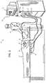
- FIG. 2is a perspective view of a console for performing a medical procedure having connection ports with indicators, according to one embodiment.
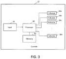
- FIG. 3is a schematic diagram of a console having connection ports with indicators, according to one embodiment.
- FIG. 2is a pictorial illustration of a system 10 for performing exemplary catheterization procedures on a heart 12 of a patient.
- a console 12has multiple ports 14 to allow for connection with equipment that may be required depending on the procedure being performed.
- the ports 14have associated indicators 16 for signaling whether each individual port should be connected to a corresponding piece of equipment. As will be described below, the indicators 16 may be selectively activated to convey whether equipment should be connected to the respective ports according to the procedure being performed.
- a processor in the console 12may receive electrical signals from equipment connected to ports 14 from which electrical activation maps, anatomic positional information, i.e., of the distal portion of the catheter, and other functional images may be prepared, such as according to the methods disclosed in U.S. Pat. Nos. 6,226,542, and 6,301,496, and 6,892,091, whose disclosures are herein incorporated by reference.
- the processor in console 12may also control a radiofrequency generator to deliver energy to one or more locations within the patient depending on the procedure, as well as control and/or receive signals from various other equipment that may be used during the procedure.
- One commercial product embodying elements of the system 10is available as the CARTO® 3 System, available from Biosense Webster, Inc. (Diamond Bar, Calif.), which is capable of producing electroanatomic maps of the heart as required. This system may be modified by those skilled in the art to embody the principles of the invention described herein.
- system 10may include a catheter 18 , which is percutaneously inserted by an operator 20 through the vascular system of a patient 22 into a chamber or vascular structure of the heart 24 .
- the catheter 18typically comprises a handle 26 , having suitable controls on the handle to enable the operator 20 to steer, position and orient the distal end of the catheter as desired.
- the distal portion of the catheter 18may contain position sensors (not shown) that provide signals to the processor of console 12 through a connection at one of the ports 14 , so that the position, orientation and/or shape of the catheter 18 within the patient 22 may be sensed.
- the connectionmay also couple one or more electrodes on the catheter 18 , as well as other sensors, such as temperature and/or contact sensors, or other components depending on the application.
- diagnostic electrodesmay be used to measure electrical characteristics of the cardiac tissue and ablation electrodes may deliver energy to form lesions.
- one electrodemay be employed to perform both functions.
- areasmay be determined to be abnormal, for example by obtaining electrical activation maps using electrodes on the catheter 18 , and then may be ablated by application of thermal energy, e.g., by passage of energy radiofrequency electrical current from the radiofrequency generator through wires to one or more electrodes on the catheter 18 .
- magnetic field generator coils 28may be driven by the console 12 through a connection at one of the ports 14 .
- the projected magnetic fieldinduces electrical signals in the coils of the position that may be indicative of their position and orientation in the magnetic fields. These signals are conveyed to the processer of the console 12 for analysis through the connection at one of the ports 14 .
- the position sensorsmay be driven in order to be sensed by coils 28 .
- the catheter 18may also be configured to provide position information through techniques such as impedance sensing.
- the console 12may be coupled through yet another of the ports 14 to body surface electrodes 30 . Tissue impedance may be measured using any suitable technique, such as those taught in U.S. Pat. Nos. 7,536,218 and 7,756,576, which are hereby incorporated by reference.
- the console 12may also include a display 32 , which may be used to provide a graphical representation 34 of the relationship of the catheter 18 to the patient's heart. Further, the console 12 may have one or more input devices, such as a keypad 36 , that may be used by the operator to specify the procedure being performed and any associated parameters, as well as other relevant information.
- a display 32which may be used to provide a graphical representation 34 of the relationship of the catheter 18 to the patient's heart.
- the console 12may have one or more input devices, such as a keypad 36 , that may be used by the operator to specify the procedure being performed and any associated parameters, as well as other relevant information.
- the system 10may also include other equipment that is connected to and controlled by the console 12 via the ports 14 , not shown in this embodiment for the sake of simplicity.
- an ECG monitormay receive signals from one or more body surface electrodes, so as to provide an ECG synchronization signal, as well as other sensors used to measure characteristics of the patient.
- the systemmay also include a reference position sensor, on an externally-applied reference patch attached to the exterior of the subject's body or on an internally-placed catheter inserted into heart 24 and maintained in a fixed position relative to the heart, either of which may be connected to the console 12 by one or more of the ports 14 . By comparing the position of catheter 18 to that of the reference catheter or patch, its coordinates may be accurately determined relative to the heart, irrespective of heart motion.
- Other illustrative examples of equipment that may be connected to the console 12 through the ports 14include, without limitation, an irrigation pump used to supply fluid to manage the heat generated by tissue ablation, an ultrasound imaging transducer, and others.
- each portmay be associated with an indicator as shown in greater detail in FIG. 2 .
- each of the indicatorsmay be configured to provide a positive indication of whether a piece of equipment should be connected to the port for the procedure being performed.
- port 14 ais equipped with a visual indicator in the form of a light 40 a , schematically shown as being illuminated or otherwise activated to convey that a piece of equipment should be coupled to a connector 42 a of port 14 a .
- the indicator light 40 b of port 14 bis schematically shown to be off so that it may be understood that no equipment should be connected to port 14 b .
- any other suitable visual displaymay be used, either illuminated or not.
- a liquid crystal display or the likemay be used to designate positively or negatively whether equipment should be connected to the port.
- any suitable passive indicatormay be used to visually communicate the connection information.
- a second example of indicator 16is a mechanical indicator, such that ports 14 c and 14 d are equipped with a sliding shield 40 , which may be actuated to selectively expose or conceal the port.
- the shieldhas been activated and withdrawn for port 14 c and therefore is not visible.
- Exposure of connector 42 cindicates that a connection should be made.
- shield 44covers the connector (which correspondingly is not visible in this illustration) of port 14 d , preventing a user from connecting equipment to the port.
- this embodimentprovides a physical indication as well as a visual indication of the connection information, as the user can see whether the shield is deployed in addition to the connection being mechanically obstructed.
- a third exampleis another mechanical indicator and is shown in the context of ports 14 e and 14 f .
- connectors 42 e and 42 fare configured to extend or retract to indicate whether equipment should be coupled. As shown, connector 42 e is extended, indicating that equipment should be connected. Conversely, connector 42 f is retracted and in a recessed position to indicate that equipment should not be connected.
- This configurationalso provides both physical and visual indication of the connection status of a port.
- any suitable mechanical actuationmay be employed either to make a connector available, thus indicating that equipment should be connected, or unavailable, indicating that equipment should not be connected.
- console 12provides one embodiment for implementing ports with indicators according to the techniques of this disclosure. Relevant components of console 12 are depicted with high level schematic blocks representing their functions. As shown, console 12 include a processor 50 as described above for signal processing as well as controlling the various pieces of equipment that may be coupled to console 12 via the ports 14 . Although depicted as a single processor, any number of processors or equivalent computing resources may be employed as desired. Processor 50 may be coupled by an appropriate bus to memory 52 , which may store algorithms, routines or other instructions as warranted by the functional requirements of console 12 . In the context of this disclosure, memory 52 may store a database of procedures that may be facilitated by console 12 , along with the required combination of equipment for each procedure. Processor 50 may also receive information from user input, such as keypad 36 described above, but any suitable user interface may be employed. A manual mode may also be provided to enable the user to specify which equipment will be used for a given procedure.
- user inputsuch as keypad 36 described above, but any suitable user interface may be employed.
- a manual mode
- processor 50may control indicators 16 a - 16 n to convey with equipment should be connected to the respective ports 14 .
- a subset of the indicatorsmay selectively be activated to convey that equipment should be connected to the associated ports, while the remainder of the indicators are not activated and correspondingly convey that equipment should not be connected.
- a characteristic pattern of which indicators are activated and which are deactivatedmay be associated with different procedures.
- any number n of indicatorsmay be employed and, in general, an indicator may be provided for each port as desired.
- control of indicators 16may be tailored to the type of indicator being used.
- processor 50may simply control whether they are illuminated. For other types of visual indicators, processor 50 may control the display as necessary to convey whether equipment should be attached to the corresponding port. Likewise, for shield 44 or extendable connectors 42 e and 42 f , processor 50 may control mechanical actuators to achieve the desired port configuration to indicate whether equipment should be connected. In general, the indicator may be considered activated when it signals that a piece of equipment should be connected to the associated port and may be considered deactivated when it signals that a piece of equipment should not be connected to the associated port.
- each port 14 having an indicator 16may selectively inform the user whether equipment should be connected. As such, confusion associated with connecting catheters and other equipment to console 12 may be reduced by utilizing the techniques of this disclosure.
- Activation of the indicatorsprovides a positive indication of which ports should be in use for the procedure being performed. Further, since it is readily apparent when an indicator has been activated, the operator may immediately determine when a piece of equipment needed for a procedure has not been connected, given that the associated port will have an activated indicator and nothing coupled to the port.
Landscapes
- Health & Medical Sciences (AREA)
- Life Sciences & Earth Sciences (AREA)
- Surgery (AREA)
- Engineering & Computer Science (AREA)
- Physics & Mathematics (AREA)
- Veterinary Medicine (AREA)
- Biomedical Technology (AREA)
- Public Health (AREA)
- General Health & Medical Sciences (AREA)
- Animal Behavior & Ethology (AREA)
- Molecular Biology (AREA)
- Medical Informatics (AREA)
- Heart & Thoracic Surgery (AREA)
- Nuclear Medicine, Radiotherapy & Molecular Imaging (AREA)
- Pathology (AREA)
- General Physics & Mathematics (AREA)
- Oral & Maxillofacial Surgery (AREA)
- Otolaryngology (AREA)
- Cardiology (AREA)
- Plasma & Fusion (AREA)
- Microelectronics & Electronic Packaging (AREA)
- Optics & Photonics (AREA)
- Biophysics (AREA)
- Electromagnetism (AREA)
- Radiology & Medical Imaging (AREA)
- Gynecology & Obstetrics (AREA)
- Surgical Instruments (AREA)
- Media Introduction/Drainage Providing Device (AREA)
- Electrotherapy Devices (AREA)
Abstract
Description
Claims (19)
Priority Applications (8)
| Application Number | Priority Date | Filing Date | Title |
|---|---|---|---|
| US15/157,150US10987091B2 (en) | 2016-05-17 | 2016-05-17 | System and method for catheter connections |
| AU2017202722AAU2017202722A1 (en) | 2016-05-17 | 2017-04-26 | System and method for catheter connections |
| IL252213AIL252213B (en) | 2016-05-17 | 2017-05-10 | System and method for catheter connections |
| CA2966381ACA2966381A1 (en) | 2016-05-17 | 2017-05-10 | System and method for catheter connections |
| EP17171218.5AEP3247002A1 (en) | 2016-05-17 | 2017-05-16 | System and method for catheter connections |
| JP2017097026AJP6965020B2 (en) | 2016-05-17 | 2017-05-16 | Systems and methods for catheter connection |
| RU2017116967ARU2017116967A (en) | 2016-05-17 | 2017-05-16 | System and method for catheter connections |
| CN201710350104.9ACN107374721A (en) | 2016-05-17 | 2017-05-17 | System and method for conduit connection |
Applications Claiming Priority (1)
| Application Number | Priority Date | Filing Date | Title |
|---|---|---|---|
| US15/157,150US10987091B2 (en) | 2016-05-17 | 2016-05-17 | System and method for catheter connections |
Publications (2)
| Publication Number | Publication Date |
|---|---|
| US20170333013A1 US20170333013A1 (en) | 2017-11-23 |
| US10987091B2true US10987091B2 (en) | 2021-04-27 |
Family
ID=58745042
Family Applications (1)
| Application Number | Title | Priority Date | Filing Date |
|---|---|---|---|
| US15/157,150ActiveUS10987091B2 (en) | 2016-05-17 | 2016-05-17 | System and method for catheter connections |
Country Status (8)
| Country | Link |
|---|---|
| US (1) | US10987091B2 (en) |
| EP (1) | EP3247002A1 (en) |
| JP (1) | JP6965020B2 (en) |
| CN (1) | CN107374721A (en) |
| AU (1) | AU2017202722A1 (en) |
| CA (1) | CA2966381A1 (en) |
| IL (1) | IL252213B (en) |
| RU (1) | RU2017116967A (en) |
Families Citing this family (1)
| Publication number | Priority date | Publication date | Assignee | Title |
|---|---|---|---|---|
| US12336823B2 (en)* | 2021-12-06 | 2025-06-24 | Biosense Webster (Israel) Ltd. | Catheter connection configuration system |
Citations (34)
| Publication number | Priority date | Publication date | Assignee | Title |
|---|---|---|---|---|
| US5391199A (en) | 1993-07-20 | 1995-02-21 | Biosense, Inc. | Apparatus and method for treating cardiac arrhythmias |
| US5471982A (en) | 1992-09-29 | 1995-12-05 | Ep Technologies, Inc. | Cardiac mapping and ablation systems |
| WO1996006349A1 (en) | 1994-08-23 | 1996-02-29 | California Analytical Instruments, Inc. | Improved flame ionization detector |
| WO1996005768A1 (en) | 1994-08-19 | 1996-02-29 | Biosense, Inc. | Medical diagnosis, treatment and imaging systems |
| WO1997024981A2 (en) | 1996-01-08 | 1997-07-17 | Biosense Inc. | Cardiac electro-mechanics |
| US5718241A (en) | 1995-06-07 | 1998-02-17 | Biosense, Inc. | Apparatus and method for treating cardiac arrhythmias with no discrete target |
| WO2001022536A1 (en) | 1999-09-21 | 2001-03-29 | La Mont, Llc | Electrical jackbox apparatus and method |
| US6226542B1 (en) | 1998-07-24 | 2001-05-01 | Biosense, Inc. | Three-dimensional reconstruction of intrabody organs |
| US6301496B1 (en) | 1998-07-24 | 2001-10-09 | Biosense, Inc. | Vector mapping of three-dimensionally reconstructed intrabody organs and method of display |
| US20030125780A1 (en)* | 2001-12-28 | 2003-07-03 | Belden Elisabeth L. | Connection system for a multi-polar lead |
| US6835082B2 (en) | 2002-11-18 | 2004-12-28 | Conmed Corporation | Monopolar electrosurgical multi-plug connector device and method which accepts multiple different connector plugs |
| US6892091B1 (en) | 2000-02-18 | 2005-05-10 | Biosense, Inc. | Catheter, method and apparatus for generating an electrical map of a chamber of the heart |
| US20050124980A1 (en)* | 2003-12-03 | 2005-06-09 | Sanders Scott W. | Port stem marking for catheter placement |
| US20050182466A1 (en)* | 2003-10-10 | 2005-08-18 | Atul Mahajan | Catheter and cable inspection system and method |
| US20070016007A1 (en) | 2005-07-15 | 2007-01-18 | Assaf Govari | Hybrid magnetic-based and impedance-based position sensing |
| US20070208338A1 (en)* | 2006-03-03 | 2007-09-06 | Intact Medical Corporation | Apparatus for retrieving a tissue volume with improved positioning precursor assembly |
| US20080248685A1 (en)* | 2003-11-20 | 2008-10-09 | Joe Don Sartor | Connector Systems for Electrosurgical Generator |
| US20090062786A1 (en)* | 2007-08-30 | 2009-03-05 | Garito Jon C | Tri-frequency electrosurgical instrument |
| US20090099552A1 (en) | 2007-10-12 | 2009-04-16 | Maureen Levy | Drug delivery route-based connector system and method |
| US7756576B2 (en) | 2005-08-26 | 2010-07-13 | Biosense Webster, Inc. | Position sensing and detection of skin impedance |
| US20110003516A1 (en) | 2009-07-04 | 2011-01-06 | Andreas Stihl Ag & Co. Kg | Connector system |
| US20110045680A1 (en)* | 2007-12-20 | 2011-02-24 | Beller Juergenl | Plug system for surgical devices |
| US20110270065A1 (en)* | 2010-04-29 | 2011-11-03 | Ternes David J | Implantable medical device configuration based on port usage |
| US20120278144A1 (en)* | 2009-12-21 | 2012-11-01 | Koninklijke Philips Electronics N.V. | Imaging apparatus electronic assistant |
| US20120317287A1 (en)* | 2011-06-10 | 2012-12-13 | Ofer Amitai | System and method for management of devices accessing a network infrastructure via unmanaged network elements |
| US20130036962A1 (en) | 2010-04-16 | 2013-02-14 | Wartsila Finland Oy | Mounting method of thruster |
| US20130144227A1 (en) | 2011-11-23 | 2013-06-06 | Christopher Brian Locke | Reduced-pressure systems, methods, and devices for simultaneously treating a plurality of tissue sites |
| US8473074B2 (en) | 2011-08-31 | 2013-06-25 | Greatbatch Ltd. | Lead identification system |
| US20140125482A1 (en)* | 2012-11-05 | 2014-05-08 | Depuy Spine, Inc. | Systems and Methods for Tagging and Tracking Surgical Devices and Surgical Accessories Using Radio Frequency Identification Tags |
| US8721539B2 (en) | 2010-01-20 | 2014-05-13 | EON Surgical Ltd. | Rapid laparoscopy exchange system and method of use thereof |
| US8870812B2 (en) | 2007-02-15 | 2014-10-28 | Baxter International Inc. | Dialysis system having video display with ambient light adjustment |
| US20140350655A1 (en) | 2011-08-31 | 2014-11-27 | Greatbatch Ltd. | Lead identification system |
| US8909320B2 (en) | 2009-02-20 | 2014-12-09 | MRI Interventions, Inc. | Cable management systems for MRI systems and related methods |
| US20170172675A1 (en)* | 2014-03-19 | 2017-06-22 | Intuitive Surgical Operations, Inc. | Medical devices, systems, and methods using eye gaze tracking |
Family Cites Families (7)
| Publication number | Priority date | Publication date | Assignee | Title |
|---|---|---|---|---|
| CA2678625A1 (en) | 1992-09-23 | 1994-03-31 | St. Jude Medical, Atrial Fibrillation Division, Inc. | Endocardial mapping system |
| WO2006053308A2 (en)* | 2004-11-12 | 2006-05-18 | Asthmatx, Inc. | Improved energy delivery devices and methods |
| US7869865B2 (en)* | 2005-01-07 | 2011-01-11 | Biosense Webster, Inc. | Current-based position sensing |
| EP2468351B1 (en)* | 2005-11-21 | 2019-01-09 | ACIST Medical Systems, Inc. | Medical fluid injection system |
| US20080104275A1 (en)* | 2006-10-31 | 2008-05-01 | Jason Robert Almeida | Visual guidance and verification for interconnecting nodes |
| WO2011052390A1 (en)* | 2009-10-28 | 2011-05-05 | オリンパスメディカルシステムズ株式会社 | Medical device |
| US10092742B2 (en)* | 2014-09-22 | 2018-10-09 | Ekos Corporation | Catheter system |
- 2016
- 2016-05-17USUS15/157,150patent/US10987091B2/enactiveActive
- 2017
- 2017-04-26AUAU2017202722Apatent/AU2017202722A1/ennot_activeAbandoned
- 2017-05-10CACA2966381Apatent/CA2966381A1/ennot_activeAbandoned
- 2017-05-10ILIL252213Apatent/IL252213B/enunknown
- 2017-05-16JPJP2017097026Apatent/JP6965020B2/enactiveActive
- 2017-05-16EPEP17171218.5Apatent/EP3247002A1/enactivePending
- 2017-05-16RURU2017116967Apatent/RU2017116967A/ennot_activeApplication Discontinuation
- 2017-05-17CNCN201710350104.9Apatent/CN107374721A/enactivePending
Patent Citations (38)
| Publication number | Priority date | Publication date | Assignee | Title |
|---|---|---|---|---|
| US5471982A (en) | 1992-09-29 | 1995-12-05 | Ep Technologies, Inc. | Cardiac mapping and ablation systems |
| US5391199A (en) | 1993-07-20 | 1995-02-21 | Biosense, Inc. | Apparatus and method for treating cardiac arrhythmias |
| WO1996005768A1 (en) | 1994-08-19 | 1996-02-29 | Biosense, Inc. | Medical diagnosis, treatment and imaging systems |
| WO1996006349A1 (en) | 1994-08-23 | 1996-02-29 | California Analytical Instruments, Inc. | Improved flame ionization detector |
| US5718241A (en) | 1995-06-07 | 1998-02-17 | Biosense, Inc. | Apparatus and method for treating cardiac arrhythmias with no discrete target |
| WO1997024981A2 (en) | 1996-01-08 | 1997-07-17 | Biosense Inc. | Cardiac electro-mechanics |
| US6226542B1 (en) | 1998-07-24 | 2001-05-01 | Biosense, Inc. | Three-dimensional reconstruction of intrabody organs |
| US6301496B1 (en) | 1998-07-24 | 2001-10-09 | Biosense, Inc. | Vector mapping of three-dimensionally reconstructed intrabody organs and method of display |
| WO2001022536A1 (en) | 1999-09-21 | 2001-03-29 | La Mont, Llc | Electrical jackbox apparatus and method |
| US6892091B1 (en) | 2000-02-18 | 2005-05-10 | Biosense, Inc. | Catheter, method and apparatus for generating an electrical map of a chamber of the heart |
| US20030125780A1 (en)* | 2001-12-28 | 2003-07-03 | Belden Elisabeth L. | Connection system for a multi-polar lead |
| US6835082B2 (en) | 2002-11-18 | 2004-12-28 | Conmed Corporation | Monopolar electrosurgical multi-plug connector device and method which accepts multiple different connector plugs |
| US20050182466A1 (en)* | 2003-10-10 | 2005-08-18 | Atul Mahajan | Catheter and cable inspection system and method |
| US20080248685A1 (en)* | 2003-11-20 | 2008-10-09 | Joe Don Sartor | Connector Systems for Electrosurgical Generator |
| US7766693B2 (en) | 2003-11-20 | 2010-08-03 | Covidien Ag | Connector systems for electrosurgical generator |
| US20050124980A1 (en)* | 2003-12-03 | 2005-06-09 | Sanders Scott W. | Port stem marking for catheter placement |
| US20070016007A1 (en) | 2005-07-15 | 2007-01-18 | Assaf Govari | Hybrid magnetic-based and impedance-based position sensing |
| US7536218B2 (en) | 2005-07-15 | 2009-05-19 | Biosense Webster, Inc. | Hybrid magnetic-based and impedance-based position sensing |
| US7756576B2 (en) | 2005-08-26 | 2010-07-13 | Biosense Webster, Inc. | Position sensing and detection of skin impedance |
| US20070208338A1 (en)* | 2006-03-03 | 2007-09-06 | Intact Medical Corporation | Apparatus for retrieving a tissue volume with improved positioning precursor assembly |
| US8870812B2 (en) | 2007-02-15 | 2014-10-28 | Baxter International Inc. | Dialysis system having video display with ambient light adjustment |
| US20090062786A1 (en)* | 2007-08-30 | 2009-03-05 | Garito Jon C | Tri-frequency electrosurgical instrument |
| US20090099552A1 (en) | 2007-10-12 | 2009-04-16 | Maureen Levy | Drug delivery route-based connector system and method |
| US20110045680A1 (en)* | 2007-12-20 | 2011-02-24 | Beller Juergenl | Plug system for surgical devices |
| US8449318B2 (en) | 2007-12-20 | 2013-05-28 | Erbe Elektromedizin Gmbh | Plug system for surgical devices |
| US8909320B2 (en) | 2009-02-20 | 2014-12-09 | MRI Interventions, Inc. | Cable management systems for MRI systems and related methods |
| US20110003516A1 (en) | 2009-07-04 | 2011-01-06 | Andreas Stihl Ag & Co. Kg | Connector system |
| US20120278144A1 (en)* | 2009-12-21 | 2012-11-01 | Koninklijke Philips Electronics N.V. | Imaging apparatus electronic assistant |
| US8721539B2 (en) | 2010-01-20 | 2014-05-13 | EON Surgical Ltd. | Rapid laparoscopy exchange system and method of use thereof |
| US20130036962A1 (en) | 2010-04-16 | 2013-02-14 | Wartsila Finland Oy | Mounting method of thruster |
| US20110270065A1 (en)* | 2010-04-29 | 2011-11-03 | Ternes David J | Implantable medical device configuration based on port usage |
| US8731679B2 (en) | 2010-04-29 | 2014-05-20 | Cardiac Pacemakers, Inc. | Implantable medical device configuration based on port usage |
| US20120317287A1 (en)* | 2011-06-10 | 2012-12-13 | Ofer Amitai | System and method for management of devices accessing a network infrastructure via unmanaged network elements |
| US8473074B2 (en) | 2011-08-31 | 2013-06-25 | Greatbatch Ltd. | Lead identification system |
| US20140350655A1 (en) | 2011-08-31 | 2014-11-27 | Greatbatch Ltd. | Lead identification system |
| US20130144227A1 (en) | 2011-11-23 | 2013-06-06 | Christopher Brian Locke | Reduced-pressure systems, methods, and devices for simultaneously treating a plurality of tissue sites |
| US20140125482A1 (en)* | 2012-11-05 | 2014-05-08 | Depuy Spine, Inc. | Systems and Methods for Tagging and Tracking Surgical Devices and Surgical Accessories Using Radio Frequency Identification Tags |
| US20170172675A1 (en)* | 2014-03-19 | 2017-06-22 | Intuitive Surgical Operations, Inc. | Medical devices, systems, and methods using eye gaze tracking |
Non-Patent Citations (2)
| Title |
|---|
| European Examination Report for EP Appln. No. 17171218.5; dated Feb. 6, 2019. |
| European Search Report and Written Opinion for European Application No. 17171218.5, dated Oct. 9, 2017. |
Also Published As
| Publication number | Publication date |
|---|---|
| JP6965020B2 (en) | 2021-11-10 |
| AU2017202722A1 (en) | 2017-12-07 |
| JP2017205517A (en) | 2017-11-24 |
| EP3247002A1 (en) | 2017-11-22 |
| IL252213B (en) | 2022-08-01 |
| RU2017116967A (en) | 2018-11-16 |
| CN107374721A (en) | 2017-11-24 |
| IL252213A0 (en) | 2017-07-31 |
| US20170333013A1 (en) | 2017-11-23 |
| CA2966381A1 (en) | 2017-11-17 |
Similar Documents
| Publication | Publication Date | Title |
|---|---|---|
| JP7047016B2 (en) | Alignment map using intracardiac signal | |
| JP7622162B2 (en) | Automatic display of the earliest LAT | |
| US12285258B2 (en) | 3D intracardiac activity presentation | |
| US10765371B2 (en) | Method to project a two dimensional image/photo onto a 3D reconstruction, such as an epicardial view of heart | |
| EP1962689B1 (en) | System for visualizing heart morphology during electrophysiology mapping and treatment | |
| US20090177111A1 (en) | System and method for displaying contact between a catheter and tissue | |
| AU2018203282A1 (en) | System and method for glass state view in real-time three-dimensional (3d) cardiac imaging | |
| EP2839776B1 (en) | Graphical user interface for medical imaging system | |
| EP3021744B1 (en) | System for generating electrophysiology maps | |
| US9706937B2 (en) | Ventricular electrical activity indicator | |
| CN110267586A (en) | Method and system for determining the prevalence of cardiac phenomena | |
| US10987091B2 (en) | System and method for catheter connections | |
| US20230309853A1 (en) | Noise in electro-anatomic signals | |
| CN108366825B (en) | System and method for representation and visualization of catheter applied forces and powers | |
| US11419537B2 (en) | Methods and systems for resolving catheter rendering issues | |
| CN115670635A (en) | Accurate tissue proximity | |
| US20240050017A1 (en) | Visualizing and Clustering Multiple Electrodes of a High-Definition Catheter Projected on Tissue Surface | |
| US20230263452A1 (en) | Automatic storage and display of ecg signals indicative of atrial fibrillation |
Legal Events
| Date | Code | Title | Description |
|---|---|---|---|
| AS | Assignment | Owner name:BIOSENSE WEBSTER (ISRAEL) LTD., ISRAEL Free format text:ASSIGNMENT OF ASSIGNORS INTEREST;ASSIGNORS:SHAH, KRUTI;CONTRERAS, ADRIAN;JIMENEZ, EDUARDO;AND OTHERS;SIGNING DATES FROM 20160602 TO 20160817;REEL/FRAME:039479/0154 | |
| STPP | Information on status: patent application and granting procedure in general | Free format text:NON FINAL ACTION MAILED | |
| STPP | Information on status: patent application and granting procedure in general | Free format text:RESPONSE TO NON-FINAL OFFICE ACTION ENTERED AND FORWARDED TO EXAMINER | |
| STPP | Information on status: patent application and granting procedure in general | Free format text:FINAL REJECTION MAILED | |
| STPP | Information on status: patent application and granting procedure in general | Free format text:NON FINAL ACTION MAILED | |
| STPP | Information on status: patent application and granting procedure in general | Free format text:NOTICE OF ALLOWANCE MAILED -- APPLICATION RECEIVED IN OFFICE OF PUBLICATIONS | |
| STPP | Information on status: patent application and granting procedure in general | Free format text:PUBLICATIONS -- ISSUE FEE PAYMENT RECEIVED | |
| STPP | Information on status: patent application and granting procedure in general | Free format text:PUBLICATIONS -- ISSUE FEE PAYMENT VERIFIED | |
| STCF | Information on status: patent grant | Free format text:PATENTED CASE | |
| MAFP | Maintenance fee payment | Free format text:PAYMENT OF MAINTENANCE FEE, 4TH YEAR, LARGE ENTITY (ORIGINAL EVENT CODE: M1551); ENTITY STATUS OF PATENT OWNER: LARGE ENTITY Year of fee payment:4 |