US10984253B2 - Traffic enforcement system with time tracking and integrated video capture - Google Patents
Traffic enforcement system with time tracking and integrated video captureDownload PDFInfo
- Publication number
- US10984253B2 US10984253B2US14/298,670US201414298670AUS10984253B2US 10984253 B2US10984253 B2US 10984253B2US 201414298670 AUS201414298670 AUS 201414298670AUS 10984253 B2US10984253 B2US 10984253B2
- Authority
- US
- United States
- Prior art keywords
- target vehicle
- speed
- camera
- target
- tes
- Prior art date
- Legal status (The legal status is an assumption and is not a legal conclusion. Google has not performed a legal analysis and makes no representation as to the accuracy of the status listed.)
- Active, expires
Links
Images


Classifications
- G—PHYSICS
- G06—COMPUTING OR CALCULATING; COUNTING
- G06V—IMAGE OR VIDEO RECOGNITION OR UNDERSTANDING
- G06V20/00—Scenes; Scene-specific elements
- G06V20/50—Context or environment of the image
- G06V20/52—Surveillance or monitoring of activities, e.g. for recognising suspicious objects
- G06V20/54—Surveillance or monitoring of activities, e.g. for recognising suspicious objects of traffic, e.g. cars on the road, trains or boats
- G—PHYSICS
- G02—OPTICS
- G02B—OPTICAL ELEMENTS, SYSTEMS OR APPARATUS
- G02B7/00—Mountings, adjusting means, or light-tight connections, for optical elements
- G02B7/28—Systems for automatic generation of focusing signals
- G02B7/30—Systems for automatic generation of focusing signals using parallactic triangle with a base line
- G02B7/32—Systems for automatic generation of focusing signals using parallactic triangle with a base line using active means, e.g. light emitter
- G06K9/00785—
- G—PHYSICS
- G01—MEASURING; TESTING
- G01S—RADIO DIRECTION-FINDING; RADIO NAVIGATION; DETERMINING DISTANCE OR VELOCITY BY USE OF RADIO WAVES; LOCATING OR PRESENCE-DETECTING BY USE OF THE REFLECTION OR RERADIATION OF RADIO WAVES; ANALOGOUS ARRANGEMENTS USING OTHER WAVES
- G01S13/00—Systems using the reflection or reradiation of radio waves, e.g. radar systems; Analogous systems using reflection or reradiation of waves whose nature or wavelength is irrelevant or unspecified
- G01S13/88—Radar or analogous systems specially adapted for specific applications
- G01S13/91—Radar or analogous systems specially adapted for specific applications for traffic control
- G01S13/92—Radar or analogous systems specially adapted for specific applications for traffic control for velocity measurement
- G—PHYSICS
- G01—MEASURING; TESTING
- G01S—RADIO DIRECTION-FINDING; RADIO NAVIGATION; DETERMINING DISTANCE OR VELOCITY BY USE OF RADIO WAVES; LOCATING OR PRESENCE-DETECTING BY USE OF THE REFLECTION OR RERADIATION OF RADIO WAVES; ANALOGOUS ARRANGEMENTS USING OTHER WAVES
- G01S17/00—Systems using the reflection or reradiation of electromagnetic waves other than radio waves, e.g. lidar systems
- G01S17/88—Lidar systems specially adapted for specific applications
- G—PHYSICS
- G06—COMPUTING OR CALCULATING; COUNTING
- G06T—IMAGE DATA PROCESSING OR GENERATION, IN GENERAL
- G06T7/00—Image analysis
- G06T7/20—Analysis of motion
- G—PHYSICS
- G06—COMPUTING OR CALCULATING; COUNTING
- G06V—IMAGE OR VIDEO RECOGNITION OR UNDERSTANDING
- G06V10/00—Arrangements for image or video recognition or understanding
- G06V10/20—Image preprocessing
- G06V10/24—Aligning, centring, orientation detection or correction of the image
- G—PHYSICS
- G08—SIGNALLING
- G08G—TRAFFIC CONTROL SYSTEMS
- G08G1/00—Traffic control systems for road vehicles
- G08G1/01—Detecting movement of traffic to be counted or controlled
- G08G1/017—Detecting movement of traffic to be counted or controlled identifying vehicles
- G08G1/0175—Detecting movement of traffic to be counted or controlled identifying vehicles by photographing vehicles, e.g. when violating traffic rules
- G—PHYSICS
- G08—SIGNALLING
- G08G—TRAFFIC CONTROL SYSTEMS
- G08G1/00—Traffic control systems for road vehicles
- G08G1/01—Detecting movement of traffic to be counted or controlled
- G08G1/052—Detecting movement of traffic to be counted or controlled with provision for determining speed or overspeed
- G08G1/054—Detecting movement of traffic to be counted or controlled with provision for determining speed or overspeed photographing overspeeding vehicles
- H—ELECTRICITY
- H04—ELECTRIC COMMUNICATION TECHNIQUE
- H04N—PICTORIAL COMMUNICATION, e.g. TELEVISION
- H04N23/00—Cameras or camera modules comprising electronic image sensors; Control thereof
- H04N23/60—Control of cameras or camera modules
- H04N23/62—Control of parameters via user interfaces
- H—ELECTRICITY
- H04—ELECTRIC COMMUNICATION TECHNIQUE
- H04N—PICTORIAL COMMUNICATION, e.g. TELEVISION
- H04N23/00—Cameras or camera modules comprising electronic image sensors; Control thereof
- H04N23/60—Control of cameras or camera modules
- H04N23/63—Control of cameras or camera modules by using electronic viewfinders
- H04N23/631—Graphical user interfaces [GUI] specially adapted for controlling image capture or setting capture parameters
- H04N23/632—Graphical user interfaces [GUI] specially adapted for controlling image capture or setting capture parameters for displaying or modifying preview images prior to image capturing, e.g. variety of image resolutions or capturing parameters
- H—ELECTRICITY
- H04—ELECTRIC COMMUNICATION TECHNIQUE
- H04N—PICTORIAL COMMUNICATION, e.g. TELEVISION
- H04N23/00—Cameras or camera modules comprising electronic image sensors; Control thereof
- H04N23/60—Control of cameras or camera modules
- H04N23/63—Control of cameras or camera modules by using electronic viewfinders
- H04N23/633—Control of cameras or camera modules by using electronic viewfinders for displaying additional information relating to control or operation of the camera
- H04N23/635—Region indicators; Field of view indicators
- H—ELECTRICITY
- H04—ELECTRIC COMMUNICATION TECHNIQUE
- H04N—PICTORIAL COMMUNICATION, e.g. TELEVISION
- H04N23/00—Cameras or camera modules comprising electronic image sensors; Control thereof
- H04N23/60—Control of cameras or camera modules
- H04N23/67—Focus control based on electronic image sensor signals
- H—ELECTRICITY
- H04—ELECTRIC COMMUNICATION TECHNIQUE
- H04N—PICTORIAL COMMUNICATION, e.g. TELEVISION
- H04N23/00—Cameras or camera modules comprising electronic image sensors; Control thereof
- H04N23/60—Control of cameras or camera modules
- H04N23/69—Control of means for changing angle of the field of view, e.g. optical zoom objectives or electronic zooming
- H04N5/23212—
- H04N5/23216—
- H04N5/23293—
- H04N5/232935—
- H04N5/232945—
- H04N5/23296—
- G06K2209/15—
- G—PHYSICS
- G06—COMPUTING OR CALCULATING; COUNTING
- G06T—IMAGE DATA PROCESSING OR GENERATION, IN GENERAL
- G06T2207/00—Indexing scheme for image analysis or image enhancement
- G06T2207/10—Image acquisition modality
- G06T2207/10016—Video; Image sequence
- G—PHYSICS
- G06—COMPUTING OR CALCULATING; COUNTING
- G06T—IMAGE DATA PROCESSING OR GENERATION, IN GENERAL
- G06T2207/00—Indexing scheme for image analysis or image enhancement
- G06T2207/30—Subject of image; Context of image processing
- G06T2207/30236—Traffic on road, railway or crossing
- G—PHYSICS
- G06—COMPUTING OR CALCULATING; COUNTING
- G06V—IMAGE OR VIDEO RECOGNITION OR UNDERSTANDING
- G06V20/00—Scenes; Scene-specific elements
- G06V20/60—Type of objects
- G06V20/62—Text, e.g. of license plates, overlay texts or captions on TV images
- G06V20/625—License plates
Definitions
- the present inventionrelates unit to traffic enforcement systems for law enforcement and related applications and, more particularly, to traffic enforcement systems in which practicing target tracking history and/or periodic certification is suggested or required.
- TESvehicle mounted traffic enforcement systems
- the emitted electromagnetic radiationmay also be employed to determine the range or distance of a targeted object from the emitter or TES unit.
- This range datamay be employed to inform a focal distance or zoom distance of a camera associated with the TES unit.
- U.S. Pat. No. 5,939,717 to Dunne et al.discloses a speed detection and image capture system for moving vehicles that uses a laser to determine the range to the vehicle and then focuses a video camera based on the range for capture of a still image.
- U.S. Pat. No. 7,920,251 to Chungdiscloses a speed measurement system in which a laser rangefinder is employed to trigger capture of a still image of a vehicle when the vehicle enters a predetermined range.
- Traffic enforcement system (TES) unitsutilizing radar and laser technologies have been in use for a number of years. It is typical for the law enforcement agencies utilizing these systems to require their officers to practice established tracking history procedures. In addition to the tracking history procedures, some agencies require the officers to track the target speed for a set minimum time before taking any enforcement action. Knowing the minimum tracking time period and ensuring that the minimum tracking time was observed is the responsibility of the law enforcement officer operating the TES unit.
- TESTraffic enforcement system
- TES devicesIt would be advantageous in the design of the TES devices to allow for a method of warning the operator when the date for recertification is near. This warning, for example, could be accomplished by displaying the recertification date on the device during TES device power up sequence.
- An electromagnetic signalmay be used to determine a distance to a moving target vehicle.
- a video cameraemploys the distance measurement to focus and/or zoom a field of view of the camera on the target vehicle such that the target vehicle substantially fills the field of view of the video camera.
- the distanceis continuously or periodically updated and is used to adjust the zoom and/or focus of the video camera to maintain target vehicle in the field of view of the camera of a predetermined range of distances.
- the speed or rate of travel of the target vehicleis determined continuously, periodically, or at a desired point in time or distance using the laser and the measured speed is displayed on or in association with the video image. Accordingly, a video image depicting the target vehicle in a readily visible manner along with the speed of travel thereof is captured and may be stored or transmitted to another device.
- a target range of distances within which to capture the video image and speedmay be designated.
- the target rangeis identified by determining a distance to a pair of landmarks to indicate the range between the landmarks as the target range.
- a geographic positioning system (GPS) and compass headingare useable to designate the target range and may be used to identify a posted legal speed limit associated with the target range location.
- an apparatusin the form of a handheld or vehicle mountable TES unit.
- the TES unitincludes an inclinometer that is useable to sense a non-use orientation of the TES unit, e.g., an orientation of the TES unit when laid down on a surface.
- a control module in the TES unitmay thus initiate a power conservation mode when the non-use orientation is sensed.
- the TES unitmay also include a touch sensitive display and/or other control surfaces that may receive gesture commands.
- the one gesture commandmay be used to cause transmission of a frame of the video image to a printing device for printing thereof. Other gesture commands may be used to control viewing of select images or video captures.
- This alertmay be accomplished by presenting a symbol or icon on the display of the TES unit when the minimum tracking time period has been met.
- Another example of the alertmay be to sound a beep or tone from the speaker or piezo of the TES unit when the minimum tracking time period has been met.
- the aforesaidmay be addressed by providing a method for entering the current time and date into the TES device at the time of certification or recertification.
- the methodmay also include entry of a date that the certification date expires at the time of certification or recertification.
- the methodmay include setting a warning period before the expiration date for providing a warning or reminder to the TES device operator. The method may also disable the TES if the certification expires.
- the TES devicemay include the hardware circuitry of a real time clock (RTC), GPS circuitry, or some other method of tracking the current time and date. These additional time-keeping circuits may allow the TES device to alert the operator as to the date recertification is required, the number of days remaining before certification expires, or that certification has already expired.
- RTCreal time clock
- An additional aspect of including the time-keeping circuitrymay allow the operator to set the local time and date into the traffic safety device. Allowing the operator to manipulate the time and date of the device would be optional based on the end agency requirements.
- Another improvement of the inventionmay be to allow the agency to choose the value of the minimum tracking time period to meet their requirements.
- One example of setting the agency's choice of minimum tracking time periodmay be to set a parameter into the TES unit by the manufacturer prior to the system shipping to the end enforcement agency.
- Another method of setting the minimum tracking time periodmay be to allow this parameter value to be entered into the TES unit in a service or maintenance mode.
- Yet another improvement of the inventionmay be to prohibit the TES unit from locking or storing the target data if the required minimum tracking time period was not met.
- FIG. 1is a block diagram of a traffic enforcement system (TES) unit and associated components depicted in accordance with an embodiment of the invention
- FIG. 2is a schematic block diagram illustrating hardware components of a TES unit depicted in accordance with an embodiment of the invention
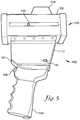
- FIG. 3is a perspective front side view of a TES unit depicted in accordance with an embodiment of the invention.
- FIG. 4is a perspective rear view of the TES unit of FIG. 3 ;
- FIG. 5is a perspective side view of the TES unit of FIG. 3 ;
- FIG. 6is a perspective front view of the TES unit of FIG. 3 ;
- FIG. 7is a perspective rear view of the TES unit of FIG. 3 ;
- FIG. 8is an illustration of an exemplary display that may be presented on a rear display of a TES unit in accordance with an embodiment of the invention.
- FIG. 9is a flow diagram of a method for capturing video of a vehicle during detecting of the speed of travel thereof depicted in accordance with an embodiment of the invention.
- FIG. 10is a flow diagram of another method for capturing video of a vehicle during detecting of the speed of travel thereof depicted in accordance with an embodiment of the invention.
- FIG. 11is flow diagram of a method for determining a range for monitoring target vehicles depicted in accordance with an embodiment of the invention.
- FIG. 12is an illustration of target vehicles traveling through a monitoring range depicted in accordance with an embodiment of the invention.
- FIG. 13is a flow diagram of a method for determining a range for monitoring target vehicles using a GPS system depicted in accordance with an embodiment
- FIG. 14is a flow diagram of an energy conservation process useable by a TES unit and depicted in accordance with an embodiment of the invention.
- FIG. 15is a block diagram of target tracking history process
- FIG. 16is a display of a minimum target tracking time alert
- FIG. 17is a block diagram example of a certification process
- FIG. 18is a diagram a host device interfaced to a traffic enforcement system
- FIG. 19is a diagram of a certification utility application
- FIG. 20is a simplified diagram of a TES with time tracking added.
- FIG. 21illustrates examples of certification display screens.
- Embodiments of the inventioninclude methods and systems that are substantially carried out and/or disposed in a handheld or vehicle mounted speed-detection and video-capture apparatus or Traffic Enforcement System (TES) unit 10 , as depicted in FIGS. 3-7 .
- TESTraffic Enforcement System
- FIGS. 3-7Traffic Enforcement System
- various components or processes of the TES unit 10might be disposed or carried out remotely from the TES unit 10 .
- the TES unit 10might be embodied in a different form, such as, for example and not limitation, components of the TES unit 10 might be integrated into a vehicle. All such configurations are within the scope of embodiments of the invention described herein.
- the TES unit 10is but one example of a suitable speed-detection and video-capture apparatus and is not intended to suggest any limitation as to the scope of use or functionality of embodiments of the invention.
- Embodiments of the inventionmay be described in the general context of computer code or machine-useable instructions, including computer-executable instructions such as program modules, being executed by a control module comprising a computer, processor, or other machine.
- program modulesincluding routines, programs, objects, components, data structures, etc., refer to code that perform particular tasks or implement particular abstract data types.
- Embodiments of the inventionmay be practiced in a variety of system configurations, including hand-held devices, consumer electronics, general-purpose computers, more specialty computing devices, etc.
- Embodiments of the inventionmay also be practiced in distributed computing environments where tasks are performed by remote-processing devices 14 that are linked directly or through a communications network 16 using wireless or wired connections.
- the TES unit 10includes one or more buses 18 that directly or indirectly couple a memory 20 , a control module 22 including one or more processors, one or more display components 24 , one or more input/output ports 26 , an illustrative power supply 28 , a video camera 30 , and an object-ranging and speed-detection module 32 .
- the TES unit 10may also include a geographic positioning system (GPS) unit 34 , a compass 36 , and an inclinometer 38 , among other components.
- the bus 18represents what may be one or more busses (such as an address bus, data bus, or combination thereof).
- the memory 20 of the TES unit 10typically includes a variety of computer-readable media integrated with the TES unit 10 or as remotely accessible external memory 40 .
- Computer-readable mediainclude computer-storage media and computer-storage devices and are mutually exclusive of communication media, e.g., carrier waves, signals, and the like.
- computer-readable mediamay comprise random access memory (RAM); read-only memory (ROM); electronically erasable programmable read-only memory (EEPROM); flash memory or other memory technologies; compact disc read-only memory (CDROM), digital versatile disks (DVD) or other optical or holographic media; magnetic cassettes unit, magnetic tape, magnetic disk storage or other magnetic storage devices, cloud based storage or remote memory accessible via wired or wireless connections or any other medium that may be used to encode desired information and be accessed by the control module 22 of the TES unit 10 .
- the memory 20can comprise one or more secure digital (SD) cards.
- SDsecure digital
- the memory 20 and the external memory 40include computer-storage media in the form of volatile and/or nonvolatile memory.
- the memories 20 , 40may be removable, non-removable, or a combination thereof.
- Exemplary hardware devicesinclude solid-state memory, hard drives, optical-disc drives, flash drives, cloud storage, etc.
- the control module 22includes one or more processors that read data from various entities such as the memories 20 , 40 or I/O components, like the video camera 30 or GPS unit 34 and carries out processes as directed received inputs or by code stored in the memories 20 , 40 .
- the display components 24present data indications to a user or other device.
- the display components 24may include a video display screen that presents a video image captured by the video camera 30 to a user, as described more fully below.
- the video display screenmay be configured as a touch interface to receive inputs from the user.
- a head-up-displaymay also be provided to present a variety of data to a user and to aid the user in aiming the TES unit 10 at a desired target.
- the I/O ports 26allow the TES unit 10 to be logically coupled to other devices or components, some of which may be built in.
- Illustrative componentsinclude a printer 42 , microphone 43 , a keyboard 45 , keypads 46 , a buzzer 58 , speaker or other audio component, a wireless device, a phone, a tablet, a personal computer, or other computing devices, etc.
- at least one I/O port 26comprises a universal serial bus (USB) port 47 or micro-USB port.
- USBuniversal serial bus
- the power supply 28is any source of electrical power sufficient to operate the TES unit 10 .
- the power supply 28may comprise an integrated battery 48 and/or removable rechargeable battery 50 , as depicted in FIG. 2 .
- the TES unit 10might also be connected to the electrical system of a vehicle in which the TES unit 10 is disposed or associated with.
- the video camera 30comprises a video camera technology available in the art now or later developed that is configured to capture a video image of a moving target object such as a vehicle.
- a video imagecomprises a plurality of still frames or images or portions thereof that are displayed successively to provide the appearance of a moving image as is known in the art.
- the camera 30may include capabilities to autofocus on the target object and to zoom in/out, e.g., magnify an image of the target object. Zooming functions may be carried out optically or via software algorithms, e.g., digitally.
- the video camera 30captures a high definition (HD) video image, e.g., a video image having greater than 480 horizontal scan lines.
- the video camera 30 and/or the control module 22may also be configured to select and store an indication of a single or multiple frames from the video image as still images.
- the object ranging and speed-detection module 32employs one or more of radar and laser technologies to emit an electromagnetic signal directed toward a target object and receiving at least a portion of the signal that is reflected by the target object.
- the object ranging and speed-detection module 32is a light detection and ranging (LIDAR) unit.
- LIDARlight detection and ranging
- the object ranging and speed-detection module 32may determine the distance to the target object based on the time between emitting and receiving the signal and may calculate the speed of travel of the vehicle based on differences in the distance measurements over time.
- the ranging and speed detection processes employed by the module 32use known methods and are thus not described in detail herein.
- the TES unit 10may include the GPS unit 34 , compass 36 , and inclinometer 38 to provide location and state information of the TES unit 10 .
- the GPS unit 34is configured to provide a geographic location of the TES unit 10 and compass 36 is useable to provide the direction or heading at which the object ranging and speed detection module 32 is directed to emit laser or radar signals.
- a GPS database 44may be included in the GPS unit 34 or accessible remotely to provide geographic information associated with the geographic location determined by the GPS unit 34 .
- the GPS database 44may include locations of roadways and legal speed limits therefor, among other data.
- the inclinometer 38measures a degree of tilt of the TES unit 10 away from vertical in one or more directions, e.g., the inclinometer 38 may detect when the TES unit 10 is laid down on a surface or is pointed toward the ground.
- the TES unit 10includes cellular or wireless communication module 52 , such as a general packet radio service (GPRS) module or another wireless communications system.
- GPRSgeneral packet radio service
- a subscriber identity module or SIM card 54can also be provided to enable access to wireless networks by conventional methods.
- the communication module 52enables wireless communication of voice or data from the TES unit 10 to disparate systems using available cellular networks.
- the TES unit 10may also include a wireless local area network (WLAN) and/or BLUETOOTH communications modules 56 to enable short range communications with other devices or networks.
- WLANwireless local area network
- BLUETOOTH communications modules 56to enable short range communications with other devices or networks.
- the TES unit 100includes a body 102 having a handle portion 104 and an upper housing 106 .
- the handle portion 104is configured similar to a pistol grip to provide a natural and comfortable grip for a user while operating the TES unit 10 .
- a trigger 108is provided near an upper end of the handle portion 104 that is operable by a user's finger to initiate target vehicle ranging and speed-detection processes as described more fully below.
- a rear display 110 , a main keyboard 112 , a head-up-display (HUD) 114 , a transmitter lens 116 , a receiver lens 118 , and a video camera 120are disposed in the upper housing 106 .
- the rear display 110is configured to present a video image captured by the video camera 120 and/or from a stored memory file.
- the rear display 110is touch sensitive and may receive touch inputs from a user.
- the touch inputsmay comprise any form of touch input, such as a tap or click on a displayed icon, a click-and-drag, a swipe, or any other gesture input.
- FIG. 8An exemplary display image 122 provided by the rear display 110 is depicted in FIG. 8 .
- the display image 122includes a video display window 124 in which a video image may be displayed.
- the window 124may include a cross-hairs, aiming reticle 126 , or other aiming indicia is superimposed thereon to aid a user in aiming the TES unit 100 at a desired target 128 .
- a control area 130is provided in the image 122 and includes a plurality of icons 132 that may be selected to provide commands, settings, or the like.
- a variety of data display regions 134may also be provided in which data such as time, date, serial number of the TES unit 10 , record number, GPS coordinates, number of GPS satellites detected, user identification, operation mode, camera settings, range to target, speed of target, speed limit, laser diameter at target, battery life, or the like may be presented.
- the main keyboard 112is disposed adjacent to the rear display 110 and provides a plurality of buttons 136 or other control surfaces that are useable to provide commands, selections, or the like. In an embodiment, one or more of the buttons 136 are redundant with respect to those of the control area 130 in the rear display 110 .
- One or more additional keyboards or control surfacesmay be provided on surfaces of the TES unit 110 , like a zoom control panel 138 , to provide quick or direct access to one or more control functions.
- the HUD 114is located on an upper surface of the upper housing 106 and includes a transparent or translucent lens through which a user may view a target to aim the TES unit 110 thereat.
- An aiming reticlemay be displayed or projected onto the lens along with the speed and/or range of the target, among other information.
- the transmitter lens 116 and receiver lens 118are located on a front surface of the upper housing 106 opposite the rear display 110 .
- the transmitter lens 116 and receiver lens 118form parts of an object ranging and speed-detection system of the TES unit 100 , like for example the object ranging and speed-detection module 32 of the TES unit 10 .
- the transmitter lens 116directs an emitted laser or light beam in a desired direction while the receiver lens 118 receives at least a portion of the emitted light that is reflected back off of a target.
- the TES unit 100also employs radar technology for one or more of object detection, vectoring, ranging, Doppler, across the road radar, and/or speed detection.
- Such embodimentsinclude radar transmitters, receivers, and/or transceivers configured to carry out such processes, as well as video analytics or other speed sensors.
- the video camera 120is also disposed in the upper housing 106 and is directed generally parallel to the transmitter and receiver lenses 116 , 118 to capture a video image of a target at which the TES unit 100 is aimed.
- the video camera 120includes optical and/or digital zoom capability that may be adjusted to provide a video image of the target in which the target encompasses a majority of a field of view of the video image and/or identifying features of the target, e.g., a license plate number, are discernable.
- the video camera 120may also include autofocus features that automatically adjust a focal plane of the video camera 120 to focus on the target with respect to a distance thereto and a level of zoom or magnification thereof.
- the video camera 120may also be operated in manual focus mode.
- the TES unit 100may include an input/output port 140 , such as a mini-B USB port, disposed on a surface thereof.
- the I/O port 140may enable coupling of the TES unit 100 to a computing system, printer, battery charger, or the like to provide data communication or charging of the battery.
- a mounting hole 142may also be provided for mounting of the TES unit 100 on a tripod, in a vehicle, or the like.
- a microphone 144may be provided adjacent the rear display 110 or at another location on the TES unit 10 .
- the microphone 144may enable use of voice commands for operation of the TES unit 10 , recording of audio data, such as notes from a user or a conversation between the user and a motorists being ticketed for speeding, among other audio data.
- a method 200 for capturing video of a vehicle during detecting of the speed of travel thereofis described in accordance with an embodiment of the invention.
- a law enforcement official or other usertypically sets up at a location near or alongside a roadway on which potential target vehicles travel.
- the TES unit 100is aimed at a target vehicle using one or both of the HUD 114 and the rear display 110 by placing the vehicle within the respective field of view or by locating an aiming reticle 126 or crosshairs on the target vehicle 128 as depicted in FIG. 8 .
- the video camera 120is first activated and focused manually or automatically on the target vehicle 128 .
- the distance to the target vehicleis detected using the object ranging and speed-detection systems, e.g., a LIDAR system, of the TES unit 100 as indicated at step 202 .
- the trigger 108is depressed to initiate the detection of the distance to the target.
- the zoom level or magnification of the video camera 120is set based on the distance to the target detected by the object ranging and speed-detection system.
- the zoom levelis set with respect to the distance to the target vehicle such that the target vehicle occupies a majority of the field of view of the video image captured by the video camera 120 .
- the target vehiclesubstantially fills the field of view, e.g., the surfaces of the vehicle lie in close proximity to the borders of the field of view of the video image.
- the zoom levelis set such that an identifying characteristic of the target vehicle like a make, model, color, or the like as well as an identifying marking, such as a license number or license plate, on the target vehicle are discernable in the video image.
- the zoom levelmay also be set to allow capture of at least a portion of the vehicle's surroundings in the video image.
- the zoom level of the display imageis sufficiently set to enable identification of a make, model, and color of the vehicle as well as viewing of a the license plate number on the target vehicle 128 .
- the location of the target vehiclemight also be identifiable based on the vehicle's surroundings captured in the video image.
- the intensity of zoomingmay be tailored to provide a desired size of the target vehicle in the video image, e.g., the zoom intensity may be tailored to substantially fill the field of view of the video image or to fill a lesser portion of the field of view and to provide a display a greater amount of the surroundings of the vehicle.
- the zoom intensityis tailored or adjusted using the zoom control panel 138 on the TES unit 100 or a redundant control provided on the rear display 110 or main keyboard 112 .
- a video image of the target vehicleis captured using the video camera 120 .
- the video imagemay be displayed on the rear display 110 in real-time and/or stored in a memory, such as the memory 20 .
- the video imagemay also be transmitted wirelessly or through a hard connection to an external memory location, like the external memory 40 , located in a vehicle of the user or at a remote location.
- video captureis initiated by the user depressing the trigger 108 .
- video captureis continuously active while the TES unit 100 is powered on, but storage of the video image is not initiated until receipt of a command to do so from the user, such as by depressing the trigger 108 .
- the videomight also be stored in a memory buffer for a predetermined duration and then committed to a storage memory when the trigger 108 is depressed.
- a buffermay allow capture of the video image of the target vehicle for a period prior to depression of the trigger 108 by the user and after the trigger is released and may account for a delayed reaction of the user and provide additional context for the recording of the desired event.
- the zoom level of the video camera 120is one of continuously, periodically, or intermittently adjusted based on movement of the target vehicle as detected by distance measurements performed by the object ranging and speed-detection systems as depicted in step 208 .
- the TES unit 100detects the distance to the target vehicle continuously, periodically, or intermittently.
- One or more of these distance measurementsare thus usable by the TES unit 100 , or more specifically the video camera 120 , to adjust the zoom level thereof to generally maintain the appearance of the target vehicle in the video image, e.g., the ratio of the size of the target vehicle with respect to the field of view of the video image is generally maintained.
- the distance measurementsmay also be used to adjust the focus of the video camera 120 or the camera's internal focus mechanisms may be employed.
- the speed of travel of the target vehicleis detected.
- the speedis detected by methods known in the art including comparison of distance measurements over a period of time to determine a distance traveled by the target vehicle over that period of time and thus the rate of travel of the target vehicle.
- the speed of the target vehiclemay be continuously, periodically, or intermittently, detected during use of the TES unit 100 or may only be detected upon depression of the trigger 108 .
- An indication of the speed of the target vehiclemay be displayed on or in association with the video image on the rear display 110 and/or on the HUD 114 .
- An indication of the speed of the target vehicle as well as any other data associated with the TES unit 100may also be stored with the video image, such as in metadata associated with the video image.
- a method 300 for capturing video of a vehicle during detecting of the speed of travel thereofis described in accordance with another embodiment of the invention (see FIG. 10 ).
- a range within which to monitor target vehiclesis received.
- the rangegenerally comprises a range of distances from the TES unit 100 with which to monitor target vehicles and may be provided in a variety of ways. For example, a user might simply provide a range of distances via the touch interface of the rear display 110 or keyboard 112 .
- the rangemay be provided by detecting a distance to a first landmark 502 , as depicted by step 402 in FIG. 11 .
- the landmarkmay comprise any object, such as a road sign, fire hydrant, tree, utility pole, a vehicle, or the like.
- a distance to a second landmark 504is detected at step 404 .
- the first and second landmarks 502 , 504thus define a range 506 within which target vehicles 508 are to be monitored when it is determined that the target vehicle 508 is within the range as depicted at step 406 .
- the rangemight also be selected using GPS, as shown in FIG. 13 .
- the location of the TES unit 100is determined using a GPS unit integrated in the TES unit 100 or associated therewith.
- a database of GPS informationmay be consulted based on the location of the TES unit 100 to identify roadways and associated speed limits thereof.
- a usermight select a portion of a roadway using the touch interface of the rear display 110 and/or keyboard 112 .
- locations of a pair of landmarksmight be determined based on the location of the TES unit 100 , a distance to the landmarks, and a compass heading of the TES unit 100 when aimed at each of the landmarks. These locations may then be employed in association with the GPS information to identify a portion of a roadway within which to monitor target vehicles.
- a compass heading of the TES unit 100 when aimed at a target vehicleis determined at a step 604 .
- the location of the target vehicleis determined base on the location of the TES unit 100 , the distance of the target vehicle form the TES unit 100 , and the compass heading therebetween as depicted in step 606 .
- a legal speed limit for the roadway at the location of the target vehiclemay be identified from the GPS data at step 608 .
- a target vehicleis monitored and is determined to have traveled outside of the range as depicted at step 304 .
- the zoom level of the video camera 120is set to a predetermined level as indicated at step 306 .
- the predetermined zoom levelcomprises any desired zoom level and may be a zoom level associated with target vehicles at a closest or furthest distance of the range (such as a closest distance 510 or furthest distance 512 of the range 508 depicted in FIG. 12 ) or may be a minimum or maximum zoom of the video camera 120 , among others.
- the predetermined zoom levelmay be selected to enable quick and/or easy zooming or focusing of the video camera 120 on a target vehicle entering a closest or furthest boundary of the range.
- the predetermined zoom levelmay be a zoom level associated with capturing video images of target vehicles at the furthest distance of the range.
- the video camera 120may be preset to a desired zoom level to immediately capture a desired video image of a target vehicle when it enters the range without requiring adjustment of the zoom level.
- the zoom levelmay be adjusted to the predetermined zoom level in preparation for monitoring a next vehicle to enter the range.
- a second target vehicleis detected as having entered the range.
- the zoom level of the video camera 120is adjusted from the predetermined zoom level based on the distance to the second target vehicle, if necessary, as depicted at step 310 .
- a video image of the second target vehicleis captured, such as in response to depression of the trigger 108 by the user, at step 312 .
- the zoom levelis adjusted to maintain the desired video image of the second target vehicle based on changing distances thereto as the second vehicle moves within the range at step 314 .
- the speed of the second target vehicleis detected as indicated at step 316 .
- the speed of the second target vehiclemay be detected continuously, periodically, intermittently, or singly as the second target vehicle is monitored.
- the capture of the video imageis initiated by detection of a speed of a target vehicle that exceeds a legal limit as defined by data associated with a geographic location of the target vehicle or as provided by a user of the TES unit 100 .
- the vehiclemight also be required to be within the set range prior to initiation capturing the video image. The detection of the speed of the target vehicle may thus precede the capturing of the video image.
- a video image of a target vehiclemay be captured throughout all or a portion of a range and the speed of the target vehicle may be simultaneously captured and displayed in association with the video image.
- the zoom level of the video camera 120is adjusted during capture of the video image based on the distance measurements of the TES unit 100 so as to track movement of the target vehicle and to enable positive identification of the target vehicle in the video image.
- the displayed detected speedmay be updated continuously, periodically, or intermittently throughout the video image so as to depict the speed of the target vehicle at a plurality of points in the video image and the range.
- the TES unit 100thus provides substantial evidence of behaviors of target vehicles, or more correctly, motorists driving the target vehicles, that may be used as proof of infractions committed by such motorists.
- the TES unit 100is in communication with a printer, such as the printer 42 , via a wireless or hard connection.
- a usermay thus provide an input to the TES unit 100 , like, for example, a swipe or other gesture on the touch interface of the rear display 110 to cause a frame of the video image to be printed on the printer.
- the printed imagemay include one or more data elements associated with the monitoring of the target vehicle, such as the detected speed thereof.
- Such a printermay be installed in a user's vehicle. The printed image may thus be provided to a motorist that has been stopped by the user as proof of the motorist's commission of an infraction.
- monitoring history of the TES unit 100 and data associated therewithmay be recorded.
- the recorded datamay be correlated with associated GPS data to display indications of the monitoring history on a map.
- target vehicle speeds monitored by the TES unit 100 or a plurality of TES units 100might be plotted on a map to depict roadways that show a propensity for speed infractions or to depict average monitored speeds on those roadways, among a variety of other possible data displays.
- the TES unit 100may also include an inclinometer that is configured to measure an angle of inclination or tilt of the TES unit 100 (see FIG. 14 ). The angle may be used by the TES unit 100 or a control module therein to determine that the TES unit 100 is not in use or at least is not in an orientation in which a target vehicle may be monitored, e.g., the TES unit 100 has been laid down on a surface like a dash board or seat of a user's vehicle or a user is holding the TES unit 100 down at their side.
- An angle indicative of such a non-use orientationmight be an angle of greater than about 90° from vertical, or more preferably greater than about 70° from vertical, however any desired angle may be employed.
- the TES unit 100is in an active state in which normal operation for monitoring target vehicles may be completed as indicated by block 702 .
- the control module of the TES unit 100initiates a timer or counter as depicted by block 706 .
- a first period of time(block 708 )
- the TES unit 100is placed in a minor energy saving state (block 710 ) in which components such as the rear display 110 , the HUD 114 , and the GPS unit, among others are powered down or turned off.
- the TES unit 100When the TES unit 100 remains in a non-use orientation (block 712 ) for a second period of time (block 714 ), such as about two minutes, the TES unit 100 is placed in a major energy conservation state as indicated by block 716 . In the major energy conservation state, components such as the video camera 120 and the object ranging and speed-detection module 32 are powered down.
- TES unit 100When the TES unit 100 remains in a non-use orientation (block 718 ) for a third period of time (block 720 ), such as about an additional eight minutes, all components and operations of the TES unit 100 are shut down as depicted by block 722 .
- the inclinometermay remain continuously or periodically active in the shut down state such that when a non-use orientation is not detected, e.g., the TES unit 100 is returned to a use orientation, e.g., the TES unit 100 is again fully powered on to resume the active state.
- the TES unit 100may also be returned to the active at any point in the power conservation process when a use orientation is detected.
- the TES unit 100thus may be powered down over a period of time to conserve battery power. By delaying full shut down of the TES unit 100 , the TES unit 100 may be laid down momentarily and then picked up again to resume use thereof without encountering delays resulting from restarting the various components or processes of the TES unit 100 that might be encountered if the TES unit 100 were immediately fully shut down.
- the energy conservation processalso allows the TES unit 100 to be automatically shut down when placed in a non-use orientation to avoid depleting batter power when the TES unit 100 is not in use.
- FIG. 15a block diagram of a typical Target Tracking History Process, indicated by reference numeral 800 , as may be performed by an officer operating the TES unit 100 is described in accordance with an embodiment of the invention.
- the officerobserves the target vehicle and how that vehicle relates to the surrounding traffic. Traffic enforcement officers often receive detailed training in estimating the speed of vehicles. This type of estimate of the target vehicle is made in block 804 .
- the officetargets the vehicle by aiming the laser beam or microwave beam from the TES unit 100 at the target vehicle.
- the radar systemwill present the Doppler return audio that is related to the speed of the target.
- the laser systemwill sound a piezo tone or other audible signal related to the quality of the laser return.
- Block 812is the block most concerning to the aspects of the invention.
- the officerobserves the speed-reading as displayed by the TES unit 100 .
- the value of the speedshould remain relatively stable and it should closely match his estimate from block 104 .
- the speed reading from the TES unit 100is valid he may proceed to block 814 to lock or store the data from the target reading. This data may contain the target's speed, direction of travel, distance to the target, time, date, etc. Having the data locked or stored may be helpful if the officer determines to proceed to take enforcement action as depicted by block 816 .
- the inventionwould provide a method for the period of the minimum tracking time to be set into the TES unit 100 at the manufacturers prior to shipping to the end law enforcement agency.
- the TES unit 100may be loaded with a set of parameters. These parameters determine the operational behavior of the TES unit 100 .
- the parameter valuesare determined by the individual requirements of the agency purchasing the TES unit 100 .
- the integer value loaded in the ‘HudTimeTrak’ parametersets the number of tenths of seconds required for the minimum target tracking time period. For example, an individual agency may require their officers to observe the target vehicle's speed reading for a minimum of two (2) seconds.
- the TES unit 100may allow the parameter values to be loaded in the service or maintenance mode. This method allows the target tracking time feature to be enabled and the minimum tracking time period to be set at the factory or at a service center.
- an individual agencymay require their officers to observe the target vehicle's speed reading for a minimum of two seconds. Previously the officer was responsible for estimating the time period that he has tracked the target, which must be for a minimum tracking time period.
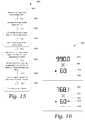
- exemplary displays that may be presented by the HUD 114are depicted in an illustration 900 in accordance with embodiments of the invention to aid description of a method to alert the officer when the target had been tracked for the minimum target tracking time.
- the example givenis for a TES unit 100 with the tracking time set to 2.5 seconds and looking through the HUD 114 .
- the top half of the illustrationdepicts the HUD 114 displayed when the officer first acquires the target readings.
- An indicia 902indicates the target distance is 990.0 feet from the TES unit 100 .
- a laser aiming reticleis depicted by 904 .
- a value indicia 906indicates the target is traveling 60 miles-per-hour (mph).
- the ‘+’ symbol 908is to indicate the target direction of travel is approaching the TES unit 100 .
- the lower half of illustration 900shows the same HUD 114 after the officer has continued to track the target for 2.5 seconds.
- the indicia 910now shows the distance to the target is 768.1 feet.
- Reference numeral 912still depicts the Laser aiming reticle.
- a value indicia 916shows the target is still traveling 60 mph and the ‘+’ 918 shows the target is still approaching the TES unit 100 . But the TES unit 100 has now displayed a symbol 916 to alert the officer the minimum target tracking time period requirement has been met.
- An audible tone or beepmay be sounded to alert the officer that the minimum target tracking time period requirement has been met. This method of audible alert may be used instead of the visible alert or in combination with the visible alert.
- the option to not allow target data to be locked or stored if the minimum target tracking time parameter was not metmay be coded in the firmware or software of the TES unit 100 .
- FIG. 17a block diagram of a certification process 1100 that may be performed at a testing laboratory for a radar or laser based TES unit is described in accordance with an embodiment of the invention.
- the certificate example shown in FIG. 17is for a radar based device.
- Blocks 1102 through 1122show the process steps the laboratory technician may take to complete the certification.
- the technicianfirst enters the device information, such as device model and serial number into a laboratory log as depicted at block 1102 .
- the technicianthen performs a tuning fork test 1104 , typically using two different tuning forks of different frequencies representing two different target speeds.
- the tuning fork testmay include the steps of: 1) placing the radar in stationary mode of operation; 2) placing the range control in maximum position; 3) placing the antenna in the transmit mode by releasing the hold switch or putting the radar unit in run mode; 4) lightly striking a lower speed fork on a hard non-metallic surface and holding the tuning fork approximately one inch in front of the antenna; 5) verifying that the target speed displays the same as the speed stamped on the tuning fork+/ ⁇ 1 mph; 6) repeating steps 4 and 5 using the higher speed tuning fork; 7) placing the radar in a moving mode of operation; 8) using the lower speed fork, perform step 4 and verifying that the patrol speed displays the same as the speed stamped on the tuning fork+/ ⁇ 1 mph; 9) while continuing to hold the lower speed fork in front of the radar, perform step 4 on the higher speed fork, holding it in front of the radar as well; and 10) with both forks now vibrating simultaneously in front of the radar antenna, verifying that the PATROL speed reads the lower speed fork
- a transmission frequency stability test 1106is performed.
- the transmitted frequencyis required to stay within a designated frequency band for a supply voltage to the device within a range of +/ ⁇ 20% of the standard supply voltage.
- a power density test 1108is performed.
- the technicianmeasures the near-field power density of the antenna at a predetermined distance in front of the antenna.
- the power density of the antennamay not exceed a maximum signal strength, such as 5 mW/cm 2 .
- a low-voltage test 1110is performed.
- the tuning fork test 1104 described aboveis performed while the supply voltage to the device is lowered to 20% of the standard supply voltage, or to a predetermined minimum voltage. As the voltage is lowered, the speed displayed should be consistent and accurate at the minimum voltage.
- the Doppler audio test 1112includes utilizing a speed simulator and listening for a tone corresponding the speed reading of an approaching vehicle at a particular speed, and a tone corresponding to the speed reading of a receding vehicle at a particular speed.
- an internal circuit test 1114is performed.
- the internal circuit test 1114is performed in accordance with the instructions of the device manufacturer.
- a directional sensing test 1116is performed.
- the directional sensing test 1116is performed utilizing a speed simulator and verifying correct display of the speed reading of an approaching vehicle at a particular speed, and correct display of the speed reading of a receding vehicle at a particular speed.
- the low and high speed display test 1118verifies that the device accurately displays a minimum speed, such as 20 mph, and a maximum speed, such as 199 mph, for example.
- the RFI test 1120is performed.
- the RFI test 1120subjects the device to various electromagnetic frequencies and wave forms and verifies that the device consistently and accurately displays the simulated speed of a vehicle.
- the unitpasses the RFI test 1120 , the unit is certified by the technician 1122 .
- Other testsmay be performed as required by the manufacturer, certifying agency, or state law.
- the inventionwould provide a certification utility application to the certifying facility.
- the radar or laser traffic devicemay be connected to an intelligent device running the certification utility application.
- the host device 1202may be a PC, tablet, smart phone, or any intelligent device capable of running the certification utility application.
- Host device 1202is connected to the TES unit or traffic enforcement system (TES) 1206 , via a communication link 1204 .
- This communication link 1204may be cable connection such as serial communications port, universal serial bus (USB), or it may be a wireless link such as Bluetooth or WiFi.
- an example screen display of the certification utility application of the preferred embodiment, running on the host deviceis generally indicated by reference numeral 1300 .
- a technicianmay establish a communication between the host device and the TES 1206 by pressing a connect button 1302 .
- Informationmay now be shared between the host device and the TES 1206 .
- the technicianmay want to update the Time/Date in the TES 1206 to the current Time/Date in the host device by pressing the Set Time/Date button 1304 .
- the technicianmay then set the date on which the current certification was completed. This may be done by clicking a date in the calendar view 1306 or by clicking today's date box 1308 .
- the certification start datewill then be displayed in the text box 1310 .
- the technicianmay then set the date on which the current certification will expire. This may be done by clicking a date in the calendar view 1312 or by selecting a preset period for the certification period 1314 . The next certification due date will be displayed in the text box 1316 . At this time, a notification period may be selected 1318 . This parameter is the number of days prior to the expiration of the certification 1316 to have the TES 1206 start warning the operator the certification renewal is near. Several presets may be available from the drop down box 1318 or the technician may just enter a number of days in box 1318 . Check box 1320 may be selected by the technician to enable or disable the certification checking by the TES 1206 .
- Check box 1322may be used to control how the TES 1206 behaves if the certification is allowed to expire. If the box is checked the TES 1206 will not operate if the certification has expired. If left unchecked, the TES 1206 will warn the operator the certification has expired and the operator must press a button to bypass the warning. Once the above settings are made, the technician may press the Certify button 1324 and the certification information is sent to the TES 1206 . Optionally, pressing the Certify button 1324 may also update the Time/Date in the TES 1206 to the current Time/Date in the host device.
- an electronics circuit, firmware, or software to track the current time and datemay be added to the TES 1206 unit to track when the system is required to be recertified by a test facility.
- the TES as depicted in FIG. 20 reference 1400is an example of the system with the time tracking circuitry added.
- Block 1402depicts the display and user interface. In the preferred embodiment, the invention shows the status of the systems certification on this display 1402 .
- the system's electronics board containing microprocessorssuch as a micro controller unit (MCU), or a digital signal processor (DSP), or both is indicated by reference numeral 1404 .
- the certification informationmay be processed and stored by the processors in block 1404 .
- Block 1406depicts the added time tracking circuit (real time clock, GPS module, etc.) that communicates with the processors in block 1404 .
- An example of the time tracking circuitry used in a TES unitmay include the PCF2129AT integrated circuit (IC) provided by NXP semiconductors.
- the firmware loaded in the TES unit electronics processing board 1404may display information about the systems certification to the operator via the system display 1402 .
- FIG. 21shows examples of the certification information provided to the operator as illustrated on a radar system 1500 .
- the date of the required recertificationis displayed 1502 . If the days remaining prior to the required recertification has fallen to within the notification period as set by the certifying technician, screen 1504 will be displayed, notifying the operator of the number of days before the certification expires. This screen may remain on the display until the operator acknowledges the message by pressing one of the front panel switches. Screen 1506 will be displayed if the certification date has elapsed. This notifies the operator the system is no longer in certification. Depending on the option set by the certification technician, the operator may acknowledge this message by pressing a front panel switch and continue to operate or the system firmware would set the unit inoperable until the Certification Utility was use to reset the certification of the system.
Landscapes
- Engineering & Computer Science (AREA)
- Physics & Mathematics (AREA)
- General Physics & Mathematics (AREA)
- Multimedia (AREA)
- Radar, Positioning & Navigation (AREA)
- Remote Sensing (AREA)
- Signal Processing (AREA)
- Electromagnetism (AREA)
- Computer Networks & Wireless Communication (AREA)
- Theoretical Computer Science (AREA)
- Human Computer Interaction (AREA)
- Computer Vision & Pattern Recognition (AREA)
- Optics & Photonics (AREA)
- Traffic Control Systems (AREA)
- Closed-Circuit Television Systems (AREA)
Abstract
Description
Claims (16)
Priority Applications (3)
| Application Number | Priority Date | Filing Date | Title |
|---|---|---|---|
| US14/298,670US10984253B2 (en) | 2013-06-06 | 2014-06-06 | Traffic enforcement system with time tracking and integrated video capture |
| US15/728,734US20180032820A1 (en) | 2013-06-06 | 2017-10-10 | Traffic enforcement system with time tracking and integrated video capture |
| US17/234,367US20210240999A1 (en) | 2013-06-06 | 2021-04-19 | Traffic enforcement system with time tracking and integrated video capture |
Applications Claiming Priority (2)
| Application Number | Priority Date | Filing Date | Title |
|---|---|---|---|
| US201361831971P | 2013-06-06 | 2013-06-06 | |
| US14/298,670US10984253B2 (en) | 2013-06-06 | 2014-06-06 | Traffic enforcement system with time tracking and integrated video capture |
Related Child Applications (2)
| Application Number | Title | Priority Date | Filing Date |
|---|---|---|---|
| US15/728,734ContinuationUS20180032820A1 (en) | 2013-06-06 | 2017-10-10 | Traffic enforcement system with time tracking and integrated video capture |
| US17/234,367DivisionUS20210240999A1 (en) | 2013-06-06 | 2021-04-19 | Traffic enforcement system with time tracking and integrated video capture |
Publications (2)
| Publication Number | Publication Date |
|---|---|
| US20140362231A1 US20140362231A1 (en) | 2014-12-11 |
| US10984253B2true US10984253B2 (en) | 2021-04-20 |
Family
ID=52005167
Family Applications (3)
| Application Number | Title | Priority Date | Filing Date |
|---|---|---|---|
| US14/298,670Active2036-10-31US10984253B2 (en) | 2013-06-06 | 2014-06-06 | Traffic enforcement system with time tracking and integrated video capture |
| US15/728,734AbandonedUS20180032820A1 (en) | 2013-06-06 | 2017-10-10 | Traffic enforcement system with time tracking and integrated video capture |
| US17/234,367AbandonedUS20210240999A1 (en) | 2013-06-06 | 2021-04-19 | Traffic enforcement system with time tracking and integrated video capture |
Family Applications After (2)
| Application Number | Title | Priority Date | Filing Date |
|---|---|---|---|
| US15/728,734AbandonedUS20180032820A1 (en) | 2013-06-06 | 2017-10-10 | Traffic enforcement system with time tracking and integrated video capture |
| US17/234,367AbandonedUS20210240999A1 (en) | 2013-06-06 | 2021-04-19 | Traffic enforcement system with time tracking and integrated video capture |
Country Status (9)
| Country | Link |
|---|---|
| US (3) | US10984253B2 (en) |
| EP (1) | EP3005197A4 (en) |
| AU (2) | AU2014274669A1 (en) |
| BR (1) | BR112015030439A2 (en) |
| CA (1) | CA2914345A1 (en) |
| GB (2) | GB2529368B (en) |
| NZ (1) | NZ752940A (en) |
| SG (1) | SG11201509969RA (en) |
| WO (1) | WO2014197858A1 (en) |
Families Citing this family (15)
| Publication number | Priority date | Publication date | Assignee | Title |
|---|---|---|---|---|
| US10162051B2 (en)* | 2014-03-13 | 2018-12-25 | Kustom Signals, Inc. | USB/Wireless based traffic radar system |
| US9710629B2 (en) | 2014-05-13 | 2017-07-18 | Google Technology Holdings LLC | Electronic device with method for controlling access to same |
| KR20160024143A (en)* | 2014-08-25 | 2016-03-04 | 삼성전자주식회사 | Method and Electronic Device for image processing |
| US20170343651A1 (en)* | 2014-10-03 | 2017-11-30 | Kustom Signals, Inc. | Traffic Radar System with Automated Tuning Fork Test Feature |
| US10146103B2 (en)* | 2016-03-31 | 2018-12-04 | Laser Technology, Inc. | Camera module and folded optical system for laser-based speed gun |
| US10282074B2 (en)* | 2017-03-10 | 2019-05-07 | GM Global Technology Operations LLC | Method and apparatus for enhancing top view image |
| CN109670366A (en)* | 2017-10-13 | 2019-04-23 | 神讯电脑(昆山)有限公司 | The license plate identifying approach and automobile-used photographic device of automobile-used photographic device |
| JP6984448B2 (en)* | 2018-01-30 | 2021-12-22 | 住友電気工業株式会社 | Sight, radio sensor and adjustment method |
| CN108600620B (en)* | 2018-04-13 | 2021-02-23 | 上海大学 | Target tracking method of mobile robot based on electro-hydraulic adjustable-focus lens |
| US12379500B2 (en) | 2018-11-20 | 2025-08-05 | Laser Technology, Inc. | Laser ranging and speed measurement device incorporating on-board data storage with GPS, compass, excessive panning detection and voice recognition technology |
| US11663910B2 (en) | 2018-11-20 | 2023-05-30 | Laser Technology, Inc. | Handheld laser-based vehicle speed measurement device incorporating an automatic number plate recognition (ANPR) function |
| CN112927517B (en)* | 2021-01-24 | 2022-09-13 | 成笑笑 | Overload monitoring equipment closed in idle time |
| GB2612118B (en)* | 2021-10-22 | 2024-10-02 | Milestone Systems As | Computer-implemented method and computer program for generating a thumbnail from a video stream or file, and video surveillance system |
| US12412107B2 (en) | 2021-12-29 | 2025-09-09 | Insight Direct Usa, Inc. | Blockchain recordation and validation of video data |
| US20240040115A1 (en)* | 2022-07-26 | 2024-02-01 | Insight Direct Usa, Inc. | Scheduled scene modification for extraction, preprocessing, and publishing of streaming video data |
Citations (79)
| Publication number | Priority date | Publication date | Assignee | Title |
|---|---|---|---|---|
| US3631486A (en) | 1969-06-24 | 1971-12-28 | Westinghouse Electric Corp | Processing method and commutation system for pulse doppler radar |
| US4214243A (en) | 1978-09-18 | 1980-07-22 | M. P. H. Industries, Inc. | Harmonic detector for traffic radar |
| US4236140A (en) | 1978-04-14 | 1980-11-25 | Kustom Electronics, Inc. | Traffic radar device |
| US4335382A (en) | 1980-03-10 | 1982-06-15 | Decatur Electronics, Inc. | Traffic radar system |
| US4335383A (en) | 1979-02-12 | 1982-06-15 | Kustom Electronics, Inc. | Method and apparatus for digitally determining the speed of a target vehicle while the radar platform vehicle is in motion |
| US4988994A (en) | 1987-08-26 | 1991-01-29 | Robot Foto Und Electronic Gmbh U. Co. Kg | Traffic monitoring device |
| US5005213A (en) | 1986-07-10 | 1991-04-02 | Varo, Inc. | Head mounted video display and remote camera system |
| US5111291A (en)* | 1990-07-06 | 1992-05-05 | Commonwealth Edison Company | Auto freeze frame display for intrusion monitoring system |
| US5111289A (en) | 1990-04-27 | 1992-05-05 | Lucas Gary L | Vehicular mounted surveillance and recording system |
| US5365462A (en)* | 1992-11-25 | 1994-11-15 | Mcbean Sr Ronald V | Instrumentation system with multiple sensor modules providing calibration date information |
| US5381155A (en)* | 1993-12-08 | 1995-01-10 | Gerber; Eliot S. | Vehicle speeding detection and identification |
| US5408330A (en) | 1991-03-25 | 1995-04-18 | Crimtec Corporation | Video incident capture system |
| US5497419A (en) | 1994-04-19 | 1996-03-05 | Prima Facie, Inc. | Method and apparatus for recording sensor data |
| US5508737A (en)* | 1994-07-06 | 1996-04-16 | Sony Corporation | Remote video viewing and recording system for remotely occurring events |
| US5508736A (en) | 1993-05-14 | 1996-04-16 | Cooper; Roger D. | Video signal processing apparatus for producing a composite signal for simultaneous display of data and video information |
| US5525996A (en) | 1995-02-10 | 1996-06-11 | Applied Concepts, Inc. | Police traffic radar for calculating and simultaneously displaying fastest target speed |
| US5528246A (en) | 1994-06-30 | 1996-06-18 | Kustom Signals, Inc. | Traffic radar with digital signal processing |
| US5528245A (en) | 1995-02-10 | 1996-06-18 | Applied Concepts, Inc. | Police traffic radar using double balanced mixer for even order harmonic suppression |
| US5563603A (en) | 1995-02-10 | 1996-10-08 | Aker; John L. | Police traffic radar using digital data transfer between antenna and counting unit |
| US5565871A (en) | 1995-02-10 | 1996-10-15 | Applied Concepts Inc. | Police traffic radar for allowing manual rejection of incorrect patrol speed display |
| US5570127A (en) | 1994-10-28 | 1996-10-29 | Schmidt; William P. | Video recording system for passenger vehicle |
| US5570093A (en) | 1995-02-10 | 1996-10-29 | Applied Concepts, Inc. | Police traffic radar using absolute signal strength information to improve target signal processing accuracy |
| US5574662A (en) | 1992-09-21 | 1996-11-12 | Tektronix, Inc. | Disk-based digital video recorder |
| WO1997033262A1 (en) | 1996-03-04 | 1997-09-12 | Laser Technology, Inc. | A speed detection and image capture system for moving vehicles |
| US5680178A (en) | 1988-07-13 | 1997-10-21 | Seiko Epson Corporation | Video multiplexing system for superimposition of scalable video data streams upon a background video data stream |
| US5689442A (en) | 1995-03-22 | 1997-11-18 | Witness Systems, Inc. | Event surveillance system |
| US5734337A (en)* | 1995-11-01 | 1998-03-31 | Kupersmit; Carl | Vehicle speed monitoring system |
| US5777575A (en) | 1996-10-09 | 1998-07-07 | Kustom Signals, Inc. | Radar switching system |
| US5790188A (en) | 1995-09-07 | 1998-08-04 | Flight Landata, Inc. | Computer controlled, 3-CCD camera, airborne, variable interference filter imaging spectrometer system |
| US5815092A (en) | 1997-04-22 | 1998-09-29 | Gregg, Iii; Eugene Stuart | Combined speed measuring device detector, speed measuring device and printer for verifying vehicle speed |
| US5864481A (en) | 1996-01-22 | 1999-01-26 | Raytheon Company | Integrated, reconfigurable man-portable modular system |
| US5912822A (en) | 1994-06-01 | 1999-06-15 | American Traffic Systems, Inc. | Frequency domain processing of Doppler signals in a traffic monitoring system |
| US5920348A (en)* | 1992-02-18 | 1999-07-06 | Nikon Corporation | Electronic camera with adjustable image readout area |
| US5935190A (en) | 1994-06-01 | 1999-08-10 | American Traffic Systems, Inc. | Traffic monitoring system |
| US6008752A (en) | 1998-09-16 | 1999-12-28 | Mph Industries, Inc. | Doppler-based traffic radar system |
| US6023236A (en) | 1998-11-30 | 2000-02-08 | Kustom Signals, Inc. | Speedometer assisted patrol speed search for DSP traffic radar |
| US6028528A (en) | 1997-10-24 | 2000-02-22 | Mobile-Vision, Inc. | Apparatus and methods for managing transfers of video recording media used for surveillance from vehicles |
| US6037977A (en) | 1994-12-23 | 2000-03-14 | Peterson; Roger | Vehicle surveillance system incorporating remote video and data input |
| US6046696A (en) | 1998-10-26 | 2000-04-04 | Db Design Llc | Apparatus and process for remote certification of doppler radar speed measuring devices |
| US6088635A (en) | 1998-09-28 | 2000-07-11 | Roadtrac, Llc | Railroad vehicle accident video recorder |
| US6278834B1 (en) | 1997-12-15 | 2001-08-21 | Matsushita Electric Industrial Co., Ltd. | Optical disc reproducing apparatus, and optical disc reproducing method for reproducing audio streams |
| US6389340B1 (en) | 1998-02-09 | 2002-05-14 | Gary A. Rayner | Vehicle data recorder |
| US6411874B2 (en)* | 1997-08-18 | 2002-06-25 | Texas A&M University Systems | Advanced law enforcement and response technology |
| US6417796B1 (en) | 1998-09-16 | 2002-07-09 | Mph Industries, Inc. | Doppler-based traffic radar system |
| US20020186297A1 (en) | 2001-06-05 | 2002-12-12 | Bakewell Charles Adams | Mobile enforcement platform and aimable violation detection and documentation system for multiple types of traffic violations across all lanes in moving traffic supporting immediate or delayed citation generation as well as homeland security monitoring activities |
| US20020186148A1 (en) | 2001-06-12 | 2002-12-12 | Koninklijke Philips Electronics N.V. | Combined laser/radar-video speed violation detector for law enforcement |
| US6501418B1 (en) | 2002-04-09 | 2002-12-31 | Applied Concepts, Inc. | Patrol speed acquisition in police Doppler radar |
| US6518881B2 (en) | 1999-02-25 | 2003-02-11 | David A. Monroe | Digital communication system for law enforcement use |
| US20030080878A1 (en) | 2001-10-30 | 2003-05-01 | Kirmuss Charles Bruno | Event-based vehicle image capture |
| US20030081121A1 (en) | 2001-10-30 | 2003-05-01 | Kirmuss Charles Bruno | Mobile digital video monitoring with pre-event recording |
| US20030081128A1 (en) | 2001-10-30 | 2003-05-01 | Kirmuss Charles Bruno | Heating and cooling of a mobile video recorder |
| US20030081127A1 (en) | 2001-10-30 | 2003-05-01 | Kirmuss Charles Bruno | Mobile digital video recording with pre-event recording |
| US20030081942A1 (en) | 2001-10-29 | 2003-05-01 | Visteon Global Technologies, Inc. | Video recorder for an automobile |
| US20030095688A1 (en) | 2001-10-30 | 2003-05-22 | Kirmuss Charles Bruno | Mobile motor vehicle identification |
| US6580386B1 (en) | 2001-08-16 | 2003-06-17 | Applied Concepts, Inc. | System and method for processing radar data |
| US6580373B1 (en) | 1998-11-30 | 2003-06-17 | Tuner Corporation | Car-mounted image record system |
| US6624611B2 (en) | 2001-10-30 | 2003-09-23 | Taw Security Concepts, Inc. | Sensing vehicle battery charging and/or engine block heating to trigger pre-heating of a mobile electronic device |
| US6630884B1 (en) | 2000-06-12 | 2003-10-07 | Lucent Technologies Inc. | Surveillance system for vehicles that captures visual or audio data |
| US20030197804A1 (en)* | 2002-04-22 | 2003-10-23 | Takeyoshi Ito | Digital camera with automatic focusing adequate for a still picture and a movie and an automatic focusing method for the same |
| US6744379B1 (en) | 2001-08-16 | 2004-06-01 | Applied Concepts, Inc. | System and method for displaying radar data |
| US20040189831A1 (en) | 2003-03-25 | 2004-09-30 | Minolta Co., Ltd. | Monitor device for moving body |
| US6831556B1 (en) | 2001-05-16 | 2004-12-14 | Digital Safety Technologies, Inc. | Composite mobile digital information system |
| US20050062642A1 (en) | 2001-08-16 | 2005-03-24 | Aker John L. | System and method for determining patrol speed |
| US20050253749A1 (en) | 2004-05-14 | 2005-11-17 | Shelton Maurice E | Traffic radar system with improved patrol speed capture |
| US6970183B1 (en) | 2000-06-14 | 2005-11-29 | E-Watch, Inc. | Multimedia surveillance and monitoring system including network configuration |
| US7068212B2 (en) | 1998-07-21 | 2006-06-27 | Applied Concepts, Inc. | Doppler complex FFT police radar with direction sensing capability |
| US7190882B2 (en) | 2001-03-19 | 2007-03-13 | Applied Concepts, Inc. | In-car digital video recording with MPEG-4 compression for police cruisers and other vehicles |
| US20070146484A1 (en)* | 2005-11-16 | 2007-06-28 | Joshua Horton | Automated video system for context-appropriate object tracking |
| US20090079960A1 (en) | 2007-09-24 | 2009-03-26 | Laser Technology, Inc. | Integrated still image, motion video and speed measurement system |
| US20100042350A1 (en) | 2008-08-12 | 2010-02-18 | Certrite Llc | Doppler radar gun certification system |
| US7676372B1 (en)* | 1999-02-16 | 2010-03-09 | Yugen Kaisha Gm&M | Prosthetic hearing device that transforms a detected speech into a speech of a speech form assistive in understanding the semantic meaning in the detected speech |
| US20100201829A1 (en) | 2009-02-09 | 2010-08-12 | Andrzej Skoskiewicz | Camera aiming using an electronic positioning system for the target |
| US20120078356A1 (en) | 2010-09-23 | 2012-03-29 | Colibri Heart Valve Llc | Percutaneously deliverable heart or blood vessel valve with frame having abluminally situated tissue membrane |
| US20120140080A1 (en)* | 2000-03-02 | 2012-06-07 | Donnelly Corporation | Vehicular video mirror system |
| US20120194357A1 (en) | 2003-05-05 | 2012-08-02 | American Traffic Solutions, Inc. | Traffic violation detection, recording, and evidence processing systems and methods |
| US20120209472A1 (en) | 2003-10-14 | 2012-08-16 | Donnelly Corporation | Vehicle vision system with night vision function |
| US8348996B2 (en) | 2006-09-19 | 2013-01-08 | Medtronic Ventor Technologies Ltd. | Valve prosthesis implantation techniques |
| US8401240B2 (en)* | 2006-11-09 | 2013-03-19 | University Of Florida Research Foundation, Inc. | Passive single camera imaging system for determining motor vehicle speed |
| US20130304200A1 (en) | 2011-10-19 | 2013-11-14 | Foundry Newco Xii, Inc. | Prosthetic heart valve devices, prosthetic mitral valves and associated systems and methods |
Family Cites Families (23)
| Publication number | Priority date | Publication date | Assignee | Title |
|---|---|---|---|---|
| JPS589928B2 (en)* | 1977-09-30 | 1983-02-23 | ミノルタ株式会社 | Steel camera with automatic and manual focus adjustment |
| EP0207162B1 (en)* | 1984-12-04 | 1993-01-20 | Konica Corporation | Automatic focus regulating method and camera with automatic focus regulator |
| US5521696A (en)* | 1989-03-27 | 1996-05-28 | Laser Technology, Inc. | Laser-based speed measuring device |
| EP0843188A3 (en)* | 1996-11-19 | 1998-12-09 | Walter Neudert | Film camera |
| WO1999040554A2 (en)* | 1998-02-06 | 1999-08-12 | Laser Technology, Inc. | Portable motor vehicle speed awareness and surveillance system |
| US6392564B1 (en)* | 1999-10-05 | 2002-05-21 | John J. Mackey | Aggressive driver monitoring and reporting system |
| KR20020018514A (en)* | 2000-09-02 | 2002-03-08 | 김성헌 | Apparatus for controling a zoom up/down function of camera system using laser distance measurement and method therefor |
| US20020117340A1 (en)* | 2001-01-31 | 2002-08-29 | Roger Stettner | Laser radar based collision avoidance system for stationary or moving vehicles, automobiles, boats and aircraft |
| US20060053075A1 (en)* | 2001-11-26 | 2006-03-09 | Aaron Roth | System and method for tracking asset usage and performance |
| US6714857B2 (en)* | 2002-02-26 | 2004-03-30 | Nnt, Inc. | System for remote monitoring of a vehicle and method of determining vehicle mileage, jurisdiction crossing and fuel consumption |
| US7840812B1 (en)* | 2002-05-24 | 2010-11-23 | Access Systems Americas, Inc. | Authentication of digital certificates used by portable computing devices |
| US20040046938A1 (en)* | 2002-09-05 | 2004-03-11 | Gary Gero | Automatic and manual lens focusing system with visual matching for motion picture camera |
| WO2007101275A1 (en)* | 2006-03-03 | 2007-09-07 | Honeywell International, Inc. | Camera with auto-focus capability |
| US20100228517A1 (en)* | 2009-03-09 | 2010-09-09 | Lasercraft, Inc. | Lidar devices with reflective optics |
| JP2011118482A (en)* | 2009-11-30 | 2011-06-16 | Fujitsu Ten Ltd | In-vehicle device and recognition support system |
| US20120235855A1 (en)* | 2011-03-18 | 2012-09-20 | University Of Florida Research Foundation Inc. | Advanced low power personnel/vehicle detecting radar |
| US9052329B2 (en)* | 2012-05-03 | 2015-06-09 | Xerox Corporation | Tire detection for accurate vehicle speed estimation |
| US8549284B1 (en)* | 2012-05-09 | 2013-10-01 | GM Global Technology Operations LLC | Tunable schemes and evaluation for certificate validity check in vehicle-to-entity communications |
| US20130322697A1 (en)* | 2012-05-31 | 2013-12-05 | Hexagon Technology Center Gmbh | Speed Calculation of a Moving Object based on Image Data |
| JP6015228B2 (en)* | 2012-08-10 | 2016-10-26 | アイシン・エィ・ダブリュ株式会社 | Intersection guidance system, method and program |
| JP5967822B2 (en)* | 2012-10-12 | 2016-08-10 | ルネサスエレクトロニクス株式会社 | In-vehicle communication system and apparatus |
| WO2014060786A1 (en)* | 2012-10-15 | 2014-04-24 | Freescale Semiconductor, Inc. | Method and apparatus for reporting traffic information |
| US20150002674A1 (en)* | 2013-06-26 | 2015-01-01 | Ford Global Technologies, Llc | Integrated vehicle traffic camera |
- 2014
- 2014-06-06CACA2914345Apatent/CA2914345A1/enactivePending
- 2014-06-06WOPCT/US2014/041404patent/WO2014197858A1/enactiveApplication Filing
- 2014-06-06EPEP14807281.2Apatent/EP3005197A4/ennot_activeWithdrawn
- 2014-06-06SGSG11201509969RApatent/SG11201509969RA/enunknown
- 2014-06-06GBGB1522210.2Apatent/GB2529368B/enactiveActive
- 2014-06-06AUAU2014274669Apatent/AU2014274669A1/ennot_activeAbandoned
- 2014-06-06NZNZ752940Apatent/NZ752940A/enunknown
- 2014-06-06GBGB1914908.7Apatent/GB2575577B/enactiveActive
- 2014-06-06BRBR112015030439Apatent/BR112015030439A2/ennot_activeIP Right Cessation
- 2014-06-06USUS14/298,670patent/US10984253B2/enactiveActive
- 2017
- 2017-10-10USUS15/728,734patent/US20180032820A1/ennot_activeAbandoned
- 2019
- 2019-07-18AUAU2019206079Apatent/AU2019206079B2/enactiveActive
- 2021
- 2021-04-19USUS17/234,367patent/US20210240999A1/ennot_activeAbandoned
Patent Citations (86)
| Publication number | Priority date | Publication date | Assignee | Title |
|---|---|---|---|---|
| US3631486A (en) | 1969-06-24 | 1971-12-28 | Westinghouse Electric Corp | Processing method and commutation system for pulse doppler radar |
| US4236140A (en) | 1978-04-14 | 1980-11-25 | Kustom Electronics, Inc. | Traffic radar device |
| US4214243A (en) | 1978-09-18 | 1980-07-22 | M. P. H. Industries, Inc. | Harmonic detector for traffic radar |
| US4335383A (en) | 1979-02-12 | 1982-06-15 | Kustom Electronics, Inc. | Method and apparatus for digitally determining the speed of a target vehicle while the radar platform vehicle is in motion |
| US4335382A (en) | 1980-03-10 | 1982-06-15 | Decatur Electronics, Inc. | Traffic radar system |
| US5005213A (en) | 1986-07-10 | 1991-04-02 | Varo, Inc. | Head mounted video display and remote camera system |
| US4988994A (en) | 1987-08-26 | 1991-01-29 | Robot Foto Und Electronic Gmbh U. Co. Kg | Traffic monitoring device |
| US5680178A (en) | 1988-07-13 | 1997-10-21 | Seiko Epson Corporation | Video multiplexing system for superimposition of scalable video data streams upon a background video data stream |
| US5111289A (en) | 1990-04-27 | 1992-05-05 | Lucas Gary L | Vehicular mounted surveillance and recording system |
| US5111291A (en)* | 1990-07-06 | 1992-05-05 | Commonwealth Edison Company | Auto freeze frame display for intrusion monitoring system |
| US5111291B1 (en)* | 1990-07-06 | 1999-09-28 | Commw Edison Co | Auto freeze frame display for intrusion monitoring system |
| US5408330A (en) | 1991-03-25 | 1995-04-18 | Crimtec Corporation | Video incident capture system |
| US5920348A (en)* | 1992-02-18 | 1999-07-06 | Nikon Corporation | Electronic camera with adjustable image readout area |
| US5574662A (en) | 1992-09-21 | 1996-11-12 | Tektronix, Inc. | Disk-based digital video recorder |
| US5365462A (en)* | 1992-11-25 | 1994-11-15 | Mcbean Sr Ronald V | Instrumentation system with multiple sensor modules providing calibration date information |
| US5508736A (en) | 1993-05-14 | 1996-04-16 | Cooper; Roger D. | Video signal processing apparatus for producing a composite signal for simultaneous display of data and video information |
| US5381155A (en)* | 1993-12-08 | 1995-01-10 | Gerber; Eliot S. | Vehicle speeding detection and identification |
| US5497419A (en) | 1994-04-19 | 1996-03-05 | Prima Facie, Inc. | Method and apparatus for recording sensor data |
| US5935190A (en) | 1994-06-01 | 1999-08-10 | American Traffic Systems, Inc. | Traffic monitoring system |
| US5912822A (en) | 1994-06-01 | 1999-06-15 | American Traffic Systems, Inc. | Frequency domain processing of Doppler signals in a traffic monitoring system |
| US5528246A (en) | 1994-06-30 | 1996-06-18 | Kustom Signals, Inc. | Traffic radar with digital signal processing |
| US5508737A (en)* | 1994-07-06 | 1996-04-16 | Sony Corporation | Remote video viewing and recording system for remotely occurring events |
| US5570127A (en) | 1994-10-28 | 1996-10-29 | Schmidt; William P. | Video recording system for passenger vehicle |
| US6037977A (en) | 1994-12-23 | 2000-03-14 | Peterson; Roger | Vehicle surveillance system incorporating remote video and data input |
| US5570093A (en) | 1995-02-10 | 1996-10-29 | Applied Concepts, Inc. | Police traffic radar using absolute signal strength information to improve target signal processing accuracy |
| US5691724A (en) | 1995-02-10 | 1997-11-25 | Aker; John L. | Police traffic radar using FFT processing to find fastest target |
| US5565871A (en) | 1995-02-10 | 1996-10-15 | Applied Concepts Inc. | Police traffic radar for allowing manual rejection of incorrect patrol speed display |
| US5563603A (en) | 1995-02-10 | 1996-10-08 | Aker; John L. | Police traffic radar using digital data transfer between antenna and counting unit |
| US5528245A (en) | 1995-02-10 | 1996-06-18 | Applied Concepts, Inc. | Police traffic radar using double balanced mixer for even order harmonic suppression |
| US5525996A (en) | 1995-02-10 | 1996-06-11 | Applied Concepts, Inc. | Police traffic radar for calculating and simultaneously displaying fastest target speed |
| US5689442A (en) | 1995-03-22 | 1997-11-18 | Witness Systems, Inc. | Event surveillance system |
| US5790188A (en) | 1995-09-07 | 1998-08-04 | Flight Landata, Inc. | Computer controlled, 3-CCD camera, airborne, variable interference filter imaging spectrometer system |
| US5734337A (en)* | 1995-11-01 | 1998-03-31 | Kupersmit; Carl | Vehicle speed monitoring system |
| US5864481A (en) | 1996-01-22 | 1999-01-26 | Raytheon Company | Integrated, reconfigurable man-portable modular system |
| WO1997033262A1 (en) | 1996-03-04 | 1997-09-12 | Laser Technology, Inc. | A speed detection and image capture system for moving vehicles |
| US5938717A (en) | 1996-03-04 | 1999-08-17 | Laser Technology, Inc. | Speed detection and image capture system for moving vehicles |
| US5777575A (en) | 1996-10-09 | 1998-07-07 | Kustom Signals, Inc. | Radar switching system |
| US5815092A (en) | 1997-04-22 | 1998-09-29 | Gregg, Iii; Eugene Stuart | Combined speed measuring device detector, speed measuring device and printer for verifying vehicle speed |
| US6411874B2 (en)* | 1997-08-18 | 2002-06-25 | Texas A&M University Systems | Advanced law enforcement and response technology |
| US6028528A (en) | 1997-10-24 | 2000-02-22 | Mobile-Vision, Inc. | Apparatus and methods for managing transfers of video recording media used for surveillance from vehicles |
| US6278834B1 (en) | 1997-12-15 | 2001-08-21 | Matsushita Electric Industrial Co., Ltd. | Optical disc reproducing apparatus, and optical disc reproducing method for reproducing audio streams |
| US6389340B1 (en) | 1998-02-09 | 2002-05-14 | Gary A. Rayner | Vehicle data recorder |
| US7068212B2 (en) | 1998-07-21 | 2006-06-27 | Applied Concepts, Inc. | Doppler complex FFT police radar with direction sensing capability |
| US6417796B1 (en) | 1998-09-16 | 2002-07-09 | Mph Industries, Inc. | Doppler-based traffic radar system |
| US6008752A (en) | 1998-09-16 | 1999-12-28 | Mph Industries, Inc. | Doppler-based traffic radar system |
| US6088635A (en) | 1998-09-28 | 2000-07-11 | Roadtrac, Llc | Railroad vehicle accident video recorder |
| US6046696A (en) | 1998-10-26 | 2000-04-04 | Db Design Llc | Apparatus and process for remote certification of doppler radar speed measuring devices |
| US6580373B1 (en) | 1998-11-30 | 2003-06-17 | Tuner Corporation | Car-mounted image record system |
| US6023236A (en) | 1998-11-30 | 2000-02-08 | Kustom Signals, Inc. | Speedometer assisted patrol speed search for DSP traffic radar |
| US7676372B1 (en)* | 1999-02-16 | 2010-03-09 | Yugen Kaisha Gm&M | Prosthetic hearing device that transforms a detected speech into a speech of a speech form assistive in understanding the semantic meaning in the detected speech |
| US6518881B2 (en) | 1999-02-25 | 2003-02-11 | David A. Monroe | Digital communication system for law enforcement use |
| US20120140080A1 (en)* | 2000-03-02 | 2012-06-07 | Donnelly Corporation | Vehicular video mirror system |
| US6630884B1 (en) | 2000-06-12 | 2003-10-07 | Lucent Technologies Inc. | Surveillance system for vehicles that captures visual or audio data |
| US6970183B1 (en) | 2000-06-14 | 2005-11-29 | E-Watch, Inc. | Multimedia surveillance and monitoring system including network configuration |
| US7190882B2 (en) | 2001-03-19 | 2007-03-13 | Applied Concepts, Inc. | In-car digital video recording with MPEG-4 compression for police cruisers and other vehicles |
| US6831556B1 (en) | 2001-05-16 | 2004-12-14 | Digital Safety Technologies, Inc. | Composite mobile digital information system |
| US20020186297A1 (en) | 2001-06-05 | 2002-12-12 | Bakewell Charles Adams | Mobile enforcement platform and aimable violation detection and documentation system for multiple types of traffic violations across all lanes in moving traffic supporting immediate or delayed citation generation as well as homeland security monitoring activities |
| US6894717B2 (en) | 2001-06-05 | 2005-05-17 | Charles Adams Bakewell | Mobile enforcement platform and aimable violation detection and documentation system for multiple types of traffic violations across all lanes in moving traffic supporting immediate or delayed citation generation as well as homeland security monitoring activities |
| US20020186148A1 (en) | 2001-06-12 | 2002-12-12 | Koninklijke Philips Electronics N.V. | Combined laser/radar-video speed violation detector for law enforcement |
| US6831593B2 (en) | 2001-08-16 | 2004-12-14 | Applied Concepts, Inc. | System and method for processing radar data |
| US6580386B1 (en) | 2001-08-16 | 2003-06-17 | Applied Concepts, Inc. | System and method for processing radar data |
| US20050062642A1 (en) | 2001-08-16 | 2005-03-24 | Aker John L. | System and method for determining patrol speed |
| US6744379B1 (en) | 2001-08-16 | 2004-06-01 | Applied Concepts, Inc. | System and method for displaying radar data |
| US6853314B1 (en) | 2001-08-16 | 2005-02-08 | Applied Concepts, Inc. | System and method for display radar data |
| US20030081942A1 (en) | 2001-10-29 | 2003-05-01 | Visteon Global Technologies, Inc. | Video recorder for an automobile |
| US20030095688A1 (en) | 2001-10-30 | 2003-05-22 | Kirmuss Charles Bruno | Mobile motor vehicle identification |
| US20030080878A1 (en) | 2001-10-30 | 2003-05-01 | Kirmuss Charles Bruno | Event-based vehicle image capture |
| US6624611B2 (en) | 2001-10-30 | 2003-09-23 | Taw Security Concepts, Inc. | Sensing vehicle battery charging and/or engine block heating to trigger pre-heating of a mobile electronic device |
| US20030081127A1 (en) | 2001-10-30 | 2003-05-01 | Kirmuss Charles Bruno | Mobile digital video recording with pre-event recording |
| US20030081128A1 (en) | 2001-10-30 | 2003-05-01 | Kirmuss Charles Bruno | Heating and cooling of a mobile video recorder |
| US20030081121A1 (en) | 2001-10-30 | 2003-05-01 | Kirmuss Charles Bruno | Mobile digital video monitoring with pre-event recording |
| US6501418B1 (en) | 2002-04-09 | 2002-12-31 | Applied Concepts, Inc. | Patrol speed acquisition in police Doppler radar |
| US20030197804A1 (en)* | 2002-04-22 | 2003-10-23 | Takeyoshi Ito | Digital camera with automatic focusing adequate for a still picture and a movie and an automatic focusing method for the same |
| US20040189831A1 (en) | 2003-03-25 | 2004-09-30 | Minolta Co., Ltd. | Monitor device for moving body |
| US20120194357A1 (en) | 2003-05-05 | 2012-08-02 | American Traffic Solutions, Inc. | Traffic violation detection, recording, and evidence processing systems and methods |
| US20120209472A1 (en) | 2003-10-14 | 2012-08-16 | Donnelly Corporation | Vehicle vision system with night vision function |
| US7091901B2 (en) | 2004-05-14 | 2006-08-15 | Kustom Signals, Inc. | Traffic radar system with improved patrol speed capture |
| US20050253749A1 (en) | 2004-05-14 | 2005-11-17 | Shelton Maurice E | Traffic radar system with improved patrol speed capture |
| US20070146484A1 (en)* | 2005-11-16 | 2007-06-28 | Joshua Horton | Automated video system for context-appropriate object tracking |
| US8348996B2 (en) | 2006-09-19 | 2013-01-08 | Medtronic Ventor Technologies Ltd. | Valve prosthesis implantation techniques |
| US8401240B2 (en)* | 2006-11-09 | 2013-03-19 | University Of Florida Research Foundation, Inc. | Passive single camera imaging system for determining motor vehicle speed |
| US20090079960A1 (en) | 2007-09-24 | 2009-03-26 | Laser Technology, Inc. | Integrated still image, motion video and speed measurement system |
| US20100042350A1 (en) | 2008-08-12 | 2010-02-18 | Certrite Llc | Doppler radar gun certification system |
| US20100201829A1 (en) | 2009-02-09 | 2010-08-12 | Andrzej Skoskiewicz | Camera aiming using an electronic positioning system for the target |
| US20120078356A1 (en) | 2010-09-23 | 2012-03-29 | Colibri Heart Valve Llc | Percutaneously deliverable heart or blood vessel valve with frame having abluminally situated tissue membrane |
| US20130304200A1 (en) | 2011-10-19 | 2013-11-14 | Foundry Newco Xii, Inc. | Prosthetic heart valve devices, prosthetic mitral valves and associated systems and methods |
Also Published As
| Publication number | Publication date |
|---|---|
| US20140362231A1 (en) | 2014-12-11 |
| CA2914345A1 (en) | 2014-12-11 |
| NZ752940A (en) | 2020-05-29 |
| SG11201509969RA (en) | 2016-01-28 |
| GB201522210D0 (en) | 2016-01-27 |
| EP3005197A4 (en) | 2017-03-01 |
| GB2575577B (en) | 2020-04-15 |
| AU2019206079B2 (en) | 2021-04-08 |
| AU2014274669A1 (en) | 2016-01-07 |
| GB2529368B (en) | 2020-03-04 |
| GB201914908D0 (en) | 2019-11-27 |
| GB2529368A (en) | 2016-02-17 |
| BR112015030439A2 (en) | 2017-07-25 |
| US20210240999A1 (en) | 2021-08-05 |
| US20180032820A1 (en) | 2018-02-01 |
| GB2575577A (en) | 2020-01-15 |
| EP3005197A1 (en) | 2016-04-13 |
| AU2019206079A1 (en) | 2019-08-08 |
| WO2014197858A1 (en) | 2014-12-11 |
Similar Documents
| Publication | Publication Date | Title |
|---|---|---|
| US20210240999A1 (en) | Traffic enforcement system with time tracking and integrated video capture | |
| US11994592B2 (en) | Lidar-based unmanned vehicle testing method and apparatus | |
| US20160140404A1 (en) | Method and apparatus for automatically detecting use of a mobile phone | |
| CN103702029A (en) | Method and device for prompting focusing during shooting | |
| US11378384B2 (en) | Distance measurement apparatus and control method therefor | |
| CN110979318B (en) | Lane information acquisition method and device, automatic driving vehicle and storage medium | |
| KR20160127706A (en) | Navigation method and device | |
| CN110288163A (en) | Method, apparatus, equipment and the storage medium of information processing | |
| CN110706371A (en) | Block chain-based driving safety management method, system and storage medium | |
| CN112991439A (en) | Method, apparatus, electronic device, and medium for positioning target object | |
| EP3462424B1 (en) | Method and device for mobile illumination, and storage medium | |
| KR101733553B1 (en) | Apparatus and method for caring eye | |
| JP6078760B2 (en) | Driving support system, posting terminal, notification terminal, server program, posting program, and notification program | |
| JP6643606B2 (en) | Driving support system, posting terminal, notification terminal, server program, posting program, and notification program | |
| KR20130106554A (en) | System and method for providing safe drive route | |
| JP2012034216A (en) | Image providing system, image display device, and image display program | |
| US20180164435A1 (en) | Dual lense lidar and video recording assembly | |
| JP6340524B2 (en) | Driving support system, posting terminal, notification terminal, server program, posting program, and notification program | |
| CN117734723B (en) | Autopilot system, autopilot vehicle and cloud device | |
| GB2553414A (en) | Apparatus for detecting speeding vehicles | |
| CN112712678B (en) | Electronic device and photographing safety detection method | |
| CN112815961B (en) | Method and device for verifying calibration parameters of combined application sensors | |
| JP4732141B2 (en) | Infrared transmitter and infrared transmission range display method | |
| KR101885513B1 (en) | Apparatus and method for caring eye | |
| KR101822853B1 (en) | Apparatus and method for caring eye |
Legal Events
| Date | Code | Title | Description |
|---|---|---|---|
| AS | Assignment | Owner name:KUSTOM SIGNALS, INC., KANSAS Free format text:ASSIGNMENT OF ASSIGNORS INTEREST;ASSIGNOR:TELIX D.O.O.;REEL/FRAME:033156/0723 Effective date:20140608 Owner name:TELIX D.O.O., SERBIA Free format text:ASSIGNMENT OF ASSIGNORS INTEREST;ASSIGNORS:KOVACEVIC, MILOS;KOVACEVIC, ZORAN;REEL/FRAME:033156/0669 Effective date:20140608 | |
| AS | Assignment | Owner name:PNC BANK, NATIONAL ASSOCIATION, PENNSYLVANIA Free format text:SECURITY INTEREST;ASSIGNOR:KUSTOM SIGNALS, INC.;REEL/FRAME:046656/0448 Effective date:20180725 | |
| STPP | Information on status: patent application and granting procedure in general | Free format text:FINAL REJECTION MAILED | |
| FEPP | Fee payment procedure | Free format text:ENTITY STATUS SET TO SMALL (ORIGINAL EVENT CODE: SMAL); ENTITY STATUS OF PATENT OWNER: SMALL ENTITY | |
| STCV | Information on status: appeal procedure | Free format text:NOTICE OF APPEAL FILED | |
| STCV | Information on status: appeal procedure | Free format text:APPEAL BRIEF (OR SUPPLEMENTAL BRIEF) ENTERED AND FORWARDED TO EXAMINER | |
| STCV | Information on status: appeal procedure | Free format text:EXAMINER'S ANSWER TO APPEAL BRIEF MAILED | |
| STCV | Information on status: appeal procedure | Free format text:ON APPEAL -- AWAITING DECISION BY THE BOARD OF APPEALS | |
| STPP | Information on status: patent application and granting procedure in general | Free format text:NOTICE OF ALLOWANCE MAILED -- APPLICATION RECEIVED IN OFFICE OF PUBLICATIONS | |
| STPP | Information on status: patent application and granting procedure in general | Free format text:PUBLICATIONS -- ISSUE FEE PAYMENT RECEIVED | |
| STPP | Information on status: patent application and granting procedure in general | Free format text:PUBLICATIONS -- ISSUE FEE PAYMENT VERIFIED | |
| STCF | Information on status: patent grant | Free format text:PATENTED CASE | |
| MAFP | Maintenance fee payment | Free format text:PAYMENT OF MAINTENANCE FEE, 4TH YR, SMALL ENTITY (ORIGINAL EVENT CODE: M2551); ENTITY STATUS OF PATENT OWNER: SMALL ENTITY Year of fee payment:4 |