US10983661B2 - Interface for positioning an object in three-dimensional graphical space - Google Patents
Interface for positioning an object in three-dimensional graphical spaceDownload PDFInfo
- Publication number
- US10983661B2 US10983661B2US15/428,874US201715428874AUS10983661B2US 10983661 B2US10983661 B2US 10983661B2US 201715428874 AUS201715428874 AUS 201715428874AUS 10983661 B2US10983661 B2US 10983661B2
- Authority
- US
- United States
- Prior art keywords
- graphical object
- translation control
- drawing space
- user
- control
- Prior art date
- Legal status (The legal status is an assumption and is not a legal conclusion. Google has not performed a legal analysis and makes no representation as to the accuracy of the status listed.)
- Active, expires
Links
Images


Classifications
- G—PHYSICS
- G06—COMPUTING OR CALCULATING; COUNTING
- G06F—ELECTRIC DIGITAL DATA PROCESSING
- G06F3/00—Input arrangements for transferring data to be processed into a form capable of being handled by the computer; Output arrangements for transferring data from processing unit to output unit, e.g. interface arrangements
- G06F3/01—Input arrangements or combined input and output arrangements for interaction between user and computer
- G06F3/048—Interaction techniques based on graphical user interfaces [GUI]
- G06F3/0481—Interaction techniques based on graphical user interfaces [GUI] based on specific properties of the displayed interaction object or a metaphor-based environment, e.g. interaction with desktop elements like windows or icons, or assisted by a cursor's changing behaviour or appearance
- G06F3/04815—Interaction with a metaphor-based environment or interaction object displayed as three-dimensional, e.g. changing the user viewpoint with respect to the environment or object
- G—PHYSICS
- G06—COMPUTING OR CALCULATING; COUNTING
- G06F—ELECTRIC DIGITAL DATA PROCESSING
- G06F3/00—Input arrangements for transferring data to be processed into a form capable of being handled by the computer; Output arrangements for transferring data from processing unit to output unit, e.g. interface arrangements
- G06F3/01—Input arrangements or combined input and output arrangements for interaction between user and computer
- G06F3/048—Interaction techniques based on graphical user interfaces [GUI]
- G06F3/0484—Interaction techniques based on graphical user interfaces [GUI] for the control of specific functions or operations, e.g. selecting or manipulating an object, an image or a displayed text element, setting a parameter value or selecting a range
- G06F3/04845—Interaction techniques based on graphical user interfaces [GUI] for the control of specific functions or operations, e.g. selecting or manipulating an object, an image or a displayed text element, setting a parameter value or selecting a range for image manipulation, e.g. dragging, rotation, expansion or change of colour
- G—PHYSICS
- G06—COMPUTING OR CALCULATING; COUNTING
- G06T—IMAGE DATA PROCESSING OR GENERATION, IN GENERAL
- G06T19/00—Manipulating 3D models or images for computer graphics
- G06T19/20—Editing of 3D images, e.g. changing shapes or colours, aligning objects or positioning parts
- G—PHYSICS
- G06—COMPUTING OR CALCULATING; COUNTING
- G06T—IMAGE DATA PROCESSING OR GENERATION, IN GENERAL
- G06T2200/00—Indexing scheme for image data processing or generation, in general
- G06T2200/24—Indexing scheme for image data processing or generation, in general involving graphical user interfaces [GUIs]
- G—PHYSICS
- G06—COMPUTING OR CALCULATING; COUNTING
- G06T—IMAGE DATA PROCESSING OR GENERATION, IN GENERAL
- G06T2219/00—Indexing scheme for manipulating 3D models or images for computer graphics
- G06T2219/20—Indexing scheme for editing of 3D models
- G06T2219/2016—Rotation, translation, scaling
Definitions
- aspects of the technology described hereinprovide a control interface for manipulating a 3-D graphical object within a virtual drawing space.
- the controlcan be activated by selecting a graphical object or group of objects. When multiple objects are selected, the manipulations can occur as a group. In one aspect, the manipulations occur around the centroid of the 3-D graphical object, or groups of objects.
- the manipulationscan include rotation, size adjustment, and positional adjustment within the virtual drawing space.
- Selecting the z-translation controlcan cause the camera view of the drawing space to change to give the user a better perspective of the z-location of the objects.
- the new viewcan be from above, below, or to a side.
- the objectcan be moved forward towards the view or backwards away from the view using a control to the side of the screen.
- a translucent meshis displayed in the x-y coordinate plane that intersects the object upon activation of the z-translation control.
- the planecan intersect the centroid of the object.
- the planecan move as the object moves to help the user compare the depth of the object to the depth of other objects in the virtual drawing space.
- controlcomprises a visible bounding box that surrounds the selected object or objects.
- the bounding boxcomprise bars that can resize the object uniformly or non-uniformly in the X, Y, or Z dimension.
- the control interfacealso comprises controls that rotate the object around an x-axis, an y-axis, or an z-axis.
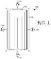
- FIG. 1shows a view of the control interface just after selection of an object, in accordance with aspects of the present disclosure
- FIG. 2shows a camera view for positioning objects within the three-dimensional graphics space, in accordance with aspects of the present disclosure
- FIG. 3shows a camera view for positioning objects within the three-dimensional graphics space relative to other objects, in accordance with aspects of the present disclosure
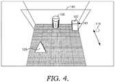
- FIG. 4shows a camera view for positioning objects within the three-dimensional graphics space relative to other objects, in accordance with aspects of the present disclosure
- FIG. 5shows a camera view for positioning objects within the three-dimensional graphics space relative to other objects, in accordance with aspects of the present disclosure
- FIG. 6shows a flow diagram for a method of positioning an object in 3D graphic space, in accordance with aspects of the present disclosure.
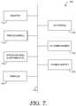
- FIG. 7is a block diagram of an exemplary computing environment suitable for use in implementing an aspect of the present disclosure.
- aspects of the technology described hereinprovide a control interface for manipulating a 3-D graphical object within a virtual drawing space.
- the controlcan be activated by selecting a graphical object or objects.
- the manipulationscan occur as a group.
- the manipulationsoccur around the centroid of the 3-D graphical object, or group of objects.
- the manipulationscan include rotation, size adjustment, and positional adjustment within the virtual drawing space.
- Selecting the z-translation controlcan cause the camera view of the drawing space to change to give the user better perspective on the z-location (or depth) of the objects.
- the new viewcan be from above, below, or to a side, instead of aligned with the z-axis.
- the objectcan be moved forward towards the viewer or backwards away from the viewer using a control to the side of the screen.
- a translucent meshis displayed in the x-y coordinate plane and intersects the object upon activation of the z-translation control.
- the planecan intersect the centroid of the object. The plane can move as the object moves to help the user compare the depth of the object to the depth of other objects in the virtual drawing space.
- controlcomprises a visible bounding box that surrounds the selected object or objects.
- the bounding boxcomprise bars that can resize the object uniformly or non-uniformly in the X, Y, or Z dimension.
- the control interfacealso comprises controls that rotate the object around an x-axis, an y-axis, or an z-axis. The rotation can be about an object-centric axis, world axis, or some other axis.
- an object-centric axisintersects the centroid of the object, but is otherwise directionally aligned with the corresponding x, y, or z world-centric axes.
- the object-centric axesare independent of the x, y, and z world axes within the virtual drawing space.
- the control interface 100includes a bounding box 102 .
- the control interface 100also includes a z-axis manipulator control 110 , an x-axis manipulator control 112 , a z-axis manipulator control 114 , and a z-translation control 116 .
- a usercan rotate the cylinder 105 about the z-axis using the z-axis manipulator control 110 .
- selecting a right side of the z-axis manipulator control 110will rotate the top of the cylinder 105 to the right from the viewer's perspective.
- selecting the left side of the z-axis manipulator control 110will rotate the top of the cylinder 105 to the left.
- the z-axis manipulator control 110can rotate the object around the z-axis in only one direction.
- the z-axis manipulator control 110can be depicted as an arrow.
- the x-axis manipulator control 112can be used to rotate the cylinder 105 about the x-axis. In an aspect, selecting one portion of the x-axis manipulator control 112 will rotate the top of the cylinder 105 towards the viewer. In an aspect, selecting the opposite side of the x-axis manipulator control 112 will rotate the top of the cylinder 105 away from the viewer. Alternatively, the x-axis manipulator control 112 can rotate the object around the x-axis in only one direction.
- the y-axis manipulator control 114can be used to rotate the cylinder 105 about the y-axis. In an aspect, selecting one portion of the y-axis manipulator control 114 will rotate the cylinder 105 a first direction. In an aspect, selecting the opposite side of the y-axis manipulator control 114 will rotate the cylinder 105 in the opposite direction. Alternatively, the y-axis manipulator control 114 can rotate the object around the y-axis in only one direction.
- the z-translation controller 116can change an object's positional depth within the virtual drawing space.
- the depth of an objectcorresponds to the z-value of the object's centroid. Increasing the z value of the centroid can be described as moving the object forward towards the viewer. Decreasing the z-value of the centroid can be described as moving the object backwards away from the viewer.
- the camera viewchanges to improve the user's perspective of the object's position along the z-axis.
- the camera viewcould move upward, downward or off to a side to improve the user's perspective.
- a track oriented in parallel to the z-axiscan appear below the control 116 and the user can change the depth of the cylinder 105 by sliding the control towards the viewer or away from the viewer along the track.
- a translucent mesh in the x-y coordinate plane that intersects the cylinder 105is displayed upon activation of the control 116 .
- the planecan intersect the centroid of the cylinder 105 .
- the planecan move as the cylinder 105 moves to help the user compare the depth of the cylinder 105 to the depth of other objects in the virtual drawing space.
- FIG. 2a positioning view for positioning objects within the three-dimensional graphics space is shown.
- the positioning viewcan be generated in response the selection of the z-translation control 116 .
- the viewis generated by moving the camera above a y-z plane that runs through the object.
- the y-z planeis relative to world space.
- the camerais viewing the scene from above the cylinder 105 at about a 45° angle from in front of the cylinder 105 .
- the positioning viewcan include a visible and translucent mesh 140 in an x-y plane that intersects the centroid of a selected object, such as the cylinder 105 .
- the visible mesh 140could take the form of any visible indication.
- the mesh planeis projected throughout the virtual drawing space.
- the objectcan be moved by sliding the z-translation control 116 forward or backwards. As the object moves, the visible mesh 140 also moves. The appearance of objects that intersect the mesh can change to indicate an intersection has occurred.
- the meshcan be transparent so that objects behind the mesh are still visible.
- the z-translation control 116is off to the side, in this example the right side, of the scene. Locating the control 116 off to the side allows the objects to be moved without occlusion by the user's hand or stylus (especially on a touchscreen device). In other words, the user's hand does not occlude the objects shown on the screen when the user is touching the control, since the control is located away from the object(s) being moved.
- the control 116is located on the left side of the screen. The location of controller may be configurable by the user. In another aspect the right or left handedness of the user is detected automatically. The control can be then located on the same side as the user's dominant hand.
- FIG. 3the positioning view is shown with the addition of a cube 107 and a pyramid 109 .
- each of the three objectsis located at different depths and the mesh 140 only intersects the cylinder 105 .
- the cube 107is visible through the transparent mesh 140 .
- the cylinder 105moves forward or backward with the mesh 140 .
- an intersection line 141appears at the point of intersection between the mesh 140 and the cube 107 .
- the cylinder 105moves backwards along with the mesh 140 .
- An intersection line 142can be seen where the mesh 140 intersects with the pyramid 109 .
- Method 600could be performed by a computing device, such as computing device 700 .
- the computing devicecan take the form of a laptop computer, a personal computer with detached display, a tablet computer, a smart phone, a holographic display, a virtual reality headset, an augmented reality headset, or some combination of the above or similar devices.
- the virtual 3D drawing space comprising the 3D objectis output for display.
- the virtual 3-D drawing spacecan be displayed in 3-D, using stereoscopic technology, or other techniques that provide a three-dimensional appearance to the display.
- the virtual 3-D drawing spacecan also be displayed in 2-D with various camera angles used to depict the 3-D space.
- a user selection of the 3D objectis received.
- the user selectioncan occur when the user contacts the 3-D object with a cursor.
- the cursorcan be controlled by a mouse, touchscreen input (e.g., stylus, finger), trackball, gaze detection, head movement, voice control, gestures, or other input techniques.
- the user selectionoccurs when the cursor contacts the 3-D object and a second input, such as a mouse click, is provided.
- a cursorobjects could be selected via voice control, keyboard, or other mechanism.
- a control around the 3D objectis displayed in response to the selection.
- the controlis a two-dimensional control.
- the controlcomprises an x-axis rotation control, an y-axis rotation control, and an z-axis rotation control.
- the controlcan also include a bounding box that enables uniform and/or non-uniform scaling of the object.
- the x-axis rotation controlis located outside of the bounding box on, or adjacent to, the x-axis.
- the y-axis rotation controlis located outside of the bounding box on, or adjacent to, the y-axis.
- the z-axis rotation controlis located outside of the bounding box on, or adjacent to, the z-axis on the side opposite the x or y-axis control.
- the z-translation controlcan be located on a side of the box without one of the other controls.
- step 607an input is received through the z-translation control.
- a camera view for the sceneis changed to be above a y-z plane that runs through the 3D object.
- the camera viewis not directly above the objects, but at an angle such as a 45° angle or 30° angle to the x-y plane.
- a visible and translucent meshis displayed in an x-y plane that passes through the object.
- the meshcan pass through the centroid of the object.
- an instruction to move the 3D objectis received.
- the instructionis received by the user dragging a control forward or backwards.
- the controlcan be located off to one side of the screen.
- the movement of the controlcan be directly proportional to the corresponding movement caused in the object.
- the ratiocould be set up to cause the object to move less than the control movement.
- the movement ratio between the controller and the objectchanges as the zoom on the scene changes. The closer the camera is to the object; the less movement is caused by moving the controller. This can give the user more granular control of the object at a close zoom.
- the object and the translucent meshare positioned according to the instruction. In other words, both the object and the mesh move together.
- computing device 700an exemplary computing device is provided and referred to generally as computing device 700 .
- the computing device 700is but one example of a suitable computing environment and is not intended to suggest any limitation as to the scope of use or functionality of aspects of the disclosure. Neither should the computing device 700 be interpreted as having any dependency or requirement relating to any one or combination of components illustrated.
- aspects of the disclosuremay be described in the general context of computer code or machine-useable instructions, including computer-useable or computer-executable instructions, such as program modules, being executed by a computer or other machine, such as a personal data assistant, a smartphone, a tablet PC, or other handheld device.
- program modulesincluding routines, programs, objects, components, data structures, and the like, refer to code that performs particular tasks or implements particular abstract data types.
- aspects of the disclosuremay be practiced in a variety of system configurations, including handheld devices, consumer electronics, general-purpose computers, more specialty computing devices, etc.
- aspects of the disclosuremay also be practiced in distributed computing environments where tasks are performed by remote-processing devices that are linked through a communications network.
- program modulesmay be located in both local and remote computer storage media including memory storage devices.
- computing device 700includes a bus 710 that directly or indirectly couples the following devices: memory 712 , one or more processors 714 , one or more presentation components 716 , one or more input/output (I/O) ports 718 , one or more I/O components 720 , and an illustrative power supply 722 .
- Bus 710represents what may be one or more busses (such as an address bus, data bus, or combination thereof).
- I/Oinput/output
- FIG. 7represents what may be one or more busses (such as an address bus, data bus, or combination thereof).
- FIG. 7is merely illustrative of an exemplary computing device that can be used in connection with one or more aspects of the present disclosure. Distinction is not made between such categories as “workstation,” “server,” “laptop,” “handheld device,” etc., as all are contemplated within the scope of FIG. 7 and with reference to “computing device.”
- Computer-readable mediacan be any available media that can be accessed by computing device 700 and includes both volatile and nonvolatile media, removable and non-removable media.
- Computer-readable mediamay comprise computer storage media and communication media.
- Computer storage mediaincludes both volatile and nonvolatile, removable and non-removable media implemented in any method or technology for storage of information such as computer-readable instructions, data structures, program modules, or other data.
- Computer storage mediaincludes, but is not limited to, RAM, ROM, EEPROM, flash memory or other memory technology, CD-ROM, digital versatile disks (DVDs) or other optical disk storage, magnetic cassettes, magnetic tape, magnetic disk storage or other magnetic storage devices, or any other medium which can be used to store the desired information and which can be accessed by computing device 700 .
- Computer storage mediadoes not comprise signals per se.
- Communication mediatypically embodies computer-readable instructions, data structures, program modules, or other data in a modulated data signal such as a carrier wave or other transport mechanism and includes any information delivery media.
- modulated data signalmeans a signal that has one or more of its characteristics set or changed in such a manner as to encode information in the signal.
- communication mediaincludes wired media, such as a wired network or direct-wired connection, and wireless media, such as acoustic, RF, infrared, and other wireless media. Combinations of any of the above should also be included within the scope of computer-readable media.
- Memory 712includes computer storage media in the form of volatile and/or nonvolatile memory.
- the memorymay be removable, non-removable, or a combination thereof.
- Exemplary hardware devicesinclude solid-state memory, hard drives, optical-disc drives, etc.
- Computing device 700includes one or more processors 714 that read data from various entities such as memory 712 or I/O components 720 .
- Presentation component(s) 716presents data indications to a user or other device.
- Exemplary presentation componentsinclude a display device, speaker, printing component, vibrating component, and the like.
- the I/O ports 718allow computing device 700 to be logically coupled to other devices, including I/O components 720 , some of which may be built in. Illustrative components include a microphone, joystick, game pad, satellite dish, scanner, printer, wireless device, etc.
- the I/O components 720may provide a natural user interface (NUI) that processes air gestures, voice, or other physiological inputs generated by a user. In some instances, inputs may be transmitted to an appropriate network element for further processing.
- NUImay implement any combination of speech recognition, touch and stylus recognition, facial recognition, biometric recognition, gesture recognition both on screen and adjacent to the screen, air gestures, head and eye tracking, and touch recognition associated with displays on the computing device 700 .
- the computing device 700may be equipped with depth cameras, such as stereoscopic camera systems, infrared camera systems, RGB camera systems, and combinations of these, for gesture detection and recognition. Additionally, the computing device 700 may be equipped with accelerometers or gyroscopes that enable detection of motion. The output of the accelerometers or gyroscopes may be provided to the display of the computing device 700 to render immersive augmented reality or virtual reality.
- computing device 700may include one or more radio(s) 724 (or similar wireless communication components).
- the radio 724transmits and receives radio or wireless communications.
- the computing device 700may be a wireless terminal adapted to receive communications and media over various wireless networks.
- Computing device 700may communicate via wireless protocols, such as code division multiple access (“CDMA”), global system for mobiles (“GSM”), or time division multiple access (“TDMA”), as well as others, to communicate with other devices.
- CDMAcode division multiple access
- GSMglobal system for mobiles
- TDMAtime division multiple access
- the radio communicationsmay be a short-range connection, a long-range connection, or a combination of both a short-range and a long-range wireless telecommunications connection.
- a short-range connectionmay include, by way of example and not limitation, a Wi-Fi® connection to a device (e.g., mobile hotspot) that provides access to a wireless communications network, such as a WLAN connection using the 802.11 protocol; a Bluetooth connection to another computing device is a second example of a short-range connection, or a near-field communication connection.
- a long-range connectionmay include a connection using, by way of example and not limitation, one or more of CDMA, GPRS, GSM, TDMA, and 802.16 protocols.
Landscapes
- Engineering & Computer Science (AREA)
- General Engineering & Computer Science (AREA)
- Theoretical Computer Science (AREA)
- Physics & Mathematics (AREA)
- General Physics & Mathematics (AREA)
- Human Computer Interaction (AREA)
- Architecture (AREA)
- Computer Graphics (AREA)
- Computer Hardware Design (AREA)
- Software Systems (AREA)
- Processing Or Creating Images (AREA)
- User Interface Of Digital Computer (AREA)
Abstract
Description
Claims (20)
Priority Applications (1)
| Application Number | Priority Date | Filing Date | Title |
|---|---|---|---|
| US15/428,874US10983661B2 (en) | 2016-10-24 | 2017-02-09 | Interface for positioning an object in three-dimensional graphical space |
Applications Claiming Priority (2)
| Application Number | Priority Date | Filing Date | Title |
|---|---|---|---|
| US201662411983P | 2016-10-24 | 2016-10-24 | |
| US15/428,874US10983661B2 (en) | 2016-10-24 | 2017-02-09 | Interface for positioning an object in three-dimensional graphical space |
Publications (2)
| Publication Number | Publication Date |
|---|---|
| US20180113596A1 US20180113596A1 (en) | 2018-04-26 |
| US10983661B2true US10983661B2 (en) | 2021-04-20 |
Family
ID=61971443
Family Applications (1)
| Application Number | Title | Priority Date | Filing Date |
|---|---|---|---|
| US15/428,874Active2038-10-08US10983661B2 (en) | 2016-10-24 | 2017-02-09 | Interface for positioning an object in three-dimensional graphical space |
Country Status (1)
| Country | Link |
|---|---|
| US (1) | US10983661B2 (en) |
Families Citing this family (10)
| Publication number | Priority date | Publication date | Assignee | Title |
|---|---|---|---|---|
| US10748345B2 (en)* | 2017-07-07 | 2020-08-18 | Adobe Inc. | 3D object composition as part of a 2D digital image through use of a visual guide |
| US10831333B2 (en)* | 2017-07-26 | 2020-11-10 | Adobe Inc. | Manipulating a camera perspective within a three-dimensional space |
| US11164395B2 (en) | 2019-05-15 | 2021-11-02 | Microsoft Technology Licensing, Llc | Structure switching in a three-dimensional environment |
| US11287947B2 (en) | 2019-05-15 | 2022-03-29 | Microsoft Technology Licensing, Llc | Contextual input in a three-dimensional environment |
| US11087560B2 (en)* | 2019-05-15 | 2021-08-10 | Microsoft Technology Licensing, Llc | Normalization of objects for a 3D environment within an authoring application |
| US11039061B2 (en) | 2019-05-15 | 2021-06-15 | Microsoft Technology Licensing, Llc | Content assistance in a three-dimensional environment |
| CN118981271A (en) | 2019-06-01 | 2024-11-19 | 苹果公司 | Device, method and graphical user interface for manipulating 3D objects on a 2D screen |
| US12153773B1 (en)* | 2020-04-27 | 2024-11-26 | Apple Inc. | Techniques for manipulating computer-generated objects |
| US12307077B1 (en) | 2020-06-16 | 2025-05-20 | Apple Inc. | Techniques for manipulating computer-generated objects in a computer graphics editor or environment |
| US12322035B2 (en)* | 2022-10-11 | 2025-06-03 | Scale AI, Inc. | Three-dimensional perspective correction |
Citations (30)
| Publication number | Priority date | Publication date | Assignee | Title |
|---|---|---|---|---|
| US6130673A (en)* | 1997-04-18 | 2000-10-10 | Silicon Graphics, Inc. | Editing a surface |
| US6448964B1 (en)* | 1999-03-15 | 2002-09-10 | Computer Associates Think, Inc. | Graphic object manipulating tool |
| US20020175948A1 (en)* | 2001-05-23 | 2002-11-28 | Nielsen Eric W. | Graphical user interface method and apparatus for interaction with finite element analysis applications |
| US20030179230A1 (en)* | 2002-03-25 | 2003-09-25 | Gerry Seidman | Method and apparatus for providing remote peer-to-peer collaborative user interfaces |
| US20050149877A1 (en)* | 1999-11-15 | 2005-07-07 | Xenogen Corporation | Graphical user interface for 3-D in-vivo imaging |
| US6918087B1 (en) | 1999-12-16 | 2005-07-12 | Autodesk, Inc. | Visual clues to navigate three-dimensional space in a computer-implemented graphics system |
| US20070247455A1 (en)* | 2006-04-21 | 2007-10-25 | Samsung Electronics Co., Ltd. | Method and apparatus for generating on-screen display using 3D graphics |
| US20080036776A1 (en) | 2004-04-16 | 2008-02-14 | Apple Inc. | User interface for controlling three-dimensional animation of an object |
| US20080291217A1 (en)* | 2007-05-25 | 2008-11-27 | Google Inc. | Viewing and navigating within panoramic images, and applications thereof |
| US20090083678A1 (en) | 2007-09-26 | 2009-03-26 | Autodesk, Inc. | Navigation system for a 3D virtual scene |
| US20090100366A1 (en)* | 2007-09-26 | 2009-04-16 | Autodesk, Inc. | Navigation system for a 3d virtual scene |
| US20100245352A1 (en) | 2009-03-26 | 2010-09-30 | Tathagata Chakraborty | Method and system for 3d object positioning in 3d virtual environments |
| US20100268457A1 (en) | 2009-04-16 | 2010-10-21 | Mccrae James | Multiscale three-dimensional navigation |
| US20120032958A1 (en) | 2010-08-06 | 2012-02-09 | Intergraph Technologies Company | 3-D Model View Manipulation Apparatus |
| US20120131498A1 (en)* | 2010-11-24 | 2012-05-24 | General Electric Company | Systems and methods for applying series level operations and comparing images using a thumbnail navigator |
| US20130135305A1 (en)* | 2010-08-05 | 2013-05-30 | Koninklijke Philips Electronics N.V. | In-plane and interactive surface mesh adaptation |
| US8477154B2 (en)* | 2006-03-20 | 2013-07-02 | Siemens Energy, Inc. | Method and system for interactive virtual inspection of modeled objects |
| US20130249912A1 (en)* | 2012-03-20 | 2013-09-26 | Ryan Michael SCHMIDT | Resolution-adaptive mesh smoothing brush |
| US20130293686A1 (en)* | 2012-05-03 | 2013-11-07 | Qualcomm Incorporated | 3d reconstruction of human subject using a mobile device |
| US20130322702A1 (en)* | 2012-06-05 | 2013-12-05 | Apple Inc. | Rendering Maps |
| US20140062998A1 (en)* | 2012-09-04 | 2014-03-06 | Google Inc. | User Interface for Orienting a Camera View Toward Surfaces in a 3D Map and Devices Incorporating the User Interface |
| US20140129990A1 (en)* | 2010-10-01 | 2014-05-08 | Smart Technologies Ulc | Interactive input system having a 3d input space |
| US20140136153A1 (en)* | 2012-11-15 | 2014-05-15 | Futurewei Technologies, Co. | Compact Scalable Three Dimensional Model Generation |
| US20140229871A1 (en) | 2011-10-27 | 2014-08-14 | The Hong Kong University Of Science And Technology | System and Method for Constrained Manipulations of 3D Objects by Multitouch Inputs |
| US20150346981A1 (en)* | 2014-05-30 | 2015-12-03 | Apple Inc. | Slider controlling visibility of objects in a 3d space |
| US9207756B2 (en) | 2011-12-30 | 2015-12-08 | Samsung Electronics Co., Ltd. | Apparatus and method for controlling 3D image |
| US9244590B1 (en)* | 2013-12-13 | 2016-01-26 | Amazon Technologies, Inc. | Three-dimensional navigation using a two-dimensional surface |
| US20170287230A1 (en)* | 2016-03-29 | 2017-10-05 | Mental Canvas LLC | Touch gestures for navigation and interacting with content in a three-dimensional space |
| US10382287B2 (en)* | 2012-02-23 | 2019-08-13 | Ajay JADHAV | Persistent node framework |
| US10558770B1 (en)* | 2015-06-12 | 2020-02-11 | Msc.Software Corporation | Finite element based direct modeling |
- 2017
- 2017-02-09USUS15/428,874patent/US10983661B2/enactiveActive
Patent Citations (31)
| Publication number | Priority date | Publication date | Assignee | Title |
|---|---|---|---|---|
| US6130673A (en)* | 1997-04-18 | 2000-10-10 | Silicon Graphics, Inc. | Editing a surface |
| US6448964B1 (en)* | 1999-03-15 | 2002-09-10 | Computer Associates Think, Inc. | Graphic object manipulating tool |
| US20050149877A1 (en)* | 1999-11-15 | 2005-07-07 | Xenogen Corporation | Graphical user interface for 3-D in-vivo imaging |
| US6918087B1 (en) | 1999-12-16 | 2005-07-12 | Autodesk, Inc. | Visual clues to navigate three-dimensional space in a computer-implemented graphics system |
| US20020175948A1 (en)* | 2001-05-23 | 2002-11-28 | Nielsen Eric W. | Graphical user interface method and apparatus for interaction with finite element analysis applications |
| US20030179230A1 (en)* | 2002-03-25 | 2003-09-25 | Gerry Seidman | Method and apparatus for providing remote peer-to-peer collaborative user interfaces |
| US20080036776A1 (en) | 2004-04-16 | 2008-02-14 | Apple Inc. | User interface for controlling three-dimensional animation of an object |
| US8477154B2 (en)* | 2006-03-20 | 2013-07-02 | Siemens Energy, Inc. | Method and system for interactive virtual inspection of modeled objects |
| US20070247455A1 (en)* | 2006-04-21 | 2007-10-25 | Samsung Electronics Co., Ltd. | Method and apparatus for generating on-screen display using 3D graphics |
| US20080291217A1 (en)* | 2007-05-25 | 2008-11-27 | Google Inc. | Viewing and navigating within panoramic images, and applications thereof |
| US20090083673A1 (en)* | 2007-09-26 | 2009-03-26 | Autodesk, Inc. | Navigation system for a 3d virtual scene |
| US20090100366A1 (en)* | 2007-09-26 | 2009-04-16 | Autodesk, Inc. | Navigation system for a 3d virtual scene |
| US20090083678A1 (en) | 2007-09-26 | 2009-03-26 | Autodesk, Inc. | Navigation system for a 3D virtual scene |
| US20100245352A1 (en) | 2009-03-26 | 2010-09-30 | Tathagata Chakraborty | Method and system for 3d object positioning in 3d virtual environments |
| US20100268457A1 (en) | 2009-04-16 | 2010-10-21 | Mccrae James | Multiscale three-dimensional navigation |
| US20130135305A1 (en)* | 2010-08-05 | 2013-05-30 | Koninklijke Philips Electronics N.V. | In-plane and interactive surface mesh adaptation |
| US20120032958A1 (en) | 2010-08-06 | 2012-02-09 | Intergraph Technologies Company | 3-D Model View Manipulation Apparatus |
| US20140129990A1 (en)* | 2010-10-01 | 2014-05-08 | Smart Technologies Ulc | Interactive input system having a 3d input space |
| US20120131498A1 (en)* | 2010-11-24 | 2012-05-24 | General Electric Company | Systems and methods for applying series level operations and comparing images using a thumbnail navigator |
| US20140229871A1 (en) | 2011-10-27 | 2014-08-14 | The Hong Kong University Of Science And Technology | System and Method for Constrained Manipulations of 3D Objects by Multitouch Inputs |
| US9207756B2 (en) | 2011-12-30 | 2015-12-08 | Samsung Electronics Co., Ltd. | Apparatus and method for controlling 3D image |
| US10382287B2 (en)* | 2012-02-23 | 2019-08-13 | Ajay JADHAV | Persistent node framework |
| US20130249912A1 (en)* | 2012-03-20 | 2013-09-26 | Ryan Michael SCHMIDT | Resolution-adaptive mesh smoothing brush |
| US20130293686A1 (en)* | 2012-05-03 | 2013-11-07 | Qualcomm Incorporated | 3d reconstruction of human subject using a mobile device |
| US20130322702A1 (en)* | 2012-06-05 | 2013-12-05 | Apple Inc. | Rendering Maps |
| US20140062998A1 (en)* | 2012-09-04 | 2014-03-06 | Google Inc. | User Interface for Orienting a Camera View Toward Surfaces in a 3D Map and Devices Incorporating the User Interface |
| US20140136153A1 (en)* | 2012-11-15 | 2014-05-15 | Futurewei Technologies, Co. | Compact Scalable Three Dimensional Model Generation |
| US9244590B1 (en)* | 2013-12-13 | 2016-01-26 | Amazon Technologies, Inc. | Three-dimensional navigation using a two-dimensional surface |
| US20150346981A1 (en)* | 2014-05-30 | 2015-12-03 | Apple Inc. | Slider controlling visibility of objects in a 3d space |
| US10558770B1 (en)* | 2015-06-12 | 2020-02-11 | Msc.Software Corporation | Finite element based direct modeling |
| US20170287230A1 (en)* | 2016-03-29 | 2017-10-05 | Mental Canvas LLC | Touch gestures for navigation and interacting with content in a three-dimensional space |
Non-Patent Citations (4)
| Title |
|---|
| "Displaying 3D models in PDFs", http://web.archive.org/web/20140419064357/http:/helpx.adobe.com/acrobat/using/displaying-3d-models-pdfs.html, Published on: Apr. 19, 2014, 10 pages. |
| Fitzmaurice, et al., "Safe 3D Navigation", In Proceedings of the symposium on Interactive 3D graphics and games, Feb. 15, 2008, pp. 7-15. |
| Khan, et al., "ViewCube: a 3D orientation indicator and controller", In Proceedings of the symposium on Interactive 3D graphics and games, Feb. 15, 2008, pp. 17-25. |
| Phillips, et al., "Automatic Viewing Control for 3D Direct Manipulation", In Proceedings of the symposium on Interactive 3D graphics, Jun. 1, 1992, pp. 71-74. |
Also Published As
| Publication number | Publication date |
|---|---|
| US20180113596A1 (en) | 2018-04-26 |
Similar Documents
| Publication | Publication Date | Title |
|---|---|---|
| US10983661B2 (en) | Interface for positioning an object in three-dimensional graphical space | |
| US10649615B2 (en) | Control interface for a three-dimensional graphical object | |
| CN110603509B (en) | Joint of direct and indirect interactions in a computer-mediated reality environment | |
| US10692287B2 (en) | Multi-step placement of virtual objects | |
| KR102098316B1 (en) | Teleportation in an augmented and/or virtual reality environment | |
| US9886102B2 (en) | Three dimensional display system and use | |
| CN107810465B (en) | System and method for generating a drawing surface | |
| US10649616B2 (en) | Volumetric multi-selection interface for selecting multiple objects in 3D space | |
| US11641460B1 (en) | Generating a volumetric representation of a capture region | |
| EP3384366B1 (en) | Methods and apparatus to navigate within virtual-reality environments | |
| US10713853B2 (en) | Automatically grouping objects in three-dimensional graphical space | |
| CN111161396B (en) | Virtual content control method, device, terminal equipment and storage medium | |
| US10614633B2 (en) | Projecting a two-dimensional image onto a three-dimensional graphical object | |
| US11961195B2 (en) | Method and device for sketch-based placement of virtual objects | |
| EP3850468B1 (en) | Snapping range for augmented reality objects | |
| JP6357412B2 (en) | Information processing apparatus, information processing system, information processing method, and program | |
| EP3702008A1 (en) | Displaying a viewport of a virtual space | |
| US20250004622A1 (en) | Object Manipulation in Graphical Environment | |
| US10529146B2 (en) | Positioning objects in three-dimensional graphical space | |
| US11087528B1 (en) | 3D object generation | |
| KR20250004534A (en) | System for sharing graphic object and operation method between multiple terminal devices and hologram devices | |
| KR20250059253A (en) | Target score provision method and system | |
| CN113934290A (en) | Virtual content display method, device and equipment |
Legal Events
| Date | Code | Title | Description |
|---|---|---|---|
| STPP | Information on status: patent application and granting procedure in general | Free format text:DOCKETED NEW CASE - READY FOR EXAMINATION | |
| AS | Assignment | Owner name:MICROSOFT TECHNOLOGY LICENSING, LLC, WASHINGTON Free format text:ASSIGNMENT OF ASSIGNORS INTEREST;ASSIGNORS:PTAK, BARRY JOHN;MONDELORE, DAVID;CULLUM, ALEXANDER CHARLES;SIGNING DATES FROM 20170207 TO 20170209;REEL/FRAME:041788/0278 | |
| STPP | Information on status: patent application and granting procedure in general | Free format text:NON FINAL ACTION MAILED | |
| STPP | Information on status: patent application and granting procedure in general | Free format text:RESPONSE TO NON-FINAL OFFICE ACTION ENTERED AND FORWARDED TO EXAMINER | |
| STPP | Information on status: patent application and granting procedure in general | Free format text:FINAL REJECTION MAILED | |
| STPP | Information on status: patent application and granting procedure in general | Free format text:RESPONSE AFTER FINAL ACTION FORWARDED TO EXAMINER | |
| STPP | Information on status: patent application and granting procedure in general | Free format text:NON FINAL ACTION MAILED | |
| STPP | Information on status: patent application and granting procedure in general | Free format text:NOTICE OF ALLOWANCE MAILED -- APPLICATION RECEIVED IN OFFICE OF PUBLICATIONS | |
| STPP | Information on status: patent application and granting procedure in general | Free format text:PUBLICATIONS -- ISSUE FEE PAYMENT RECEIVED | |
| STPP | Information on status: patent application and granting procedure in general | Free format text:PUBLICATIONS -- ISSUE FEE PAYMENT VERIFIED | |
| STCF | Information on status: patent grant | Free format text:PATENTED CASE | |
| MAFP | Maintenance fee payment | Free format text:PAYMENT OF MAINTENANCE FEE, 4TH YEAR, LARGE ENTITY (ORIGINAL EVENT CODE: M1551); ENTITY STATUS OF PATENT OWNER: LARGE ENTITY Year of fee payment:4 |