US10983511B2 - Automation control system - Google Patents
Automation control systemDownload PDFInfo
- Publication number
- US10983511B2 US10983511B2US15/879,683US201815879683AUS10983511B2US 10983511 B2US10983511 B2US 10983511B2US 201815879683 AUS201815879683 AUS 201815879683AUS 10983511 B2US10983511 B2US 10983511B2
- Authority
- US
- United States
- Prior art keywords
- automation
- computing device
- computer code
- broadcast parameters
- code
- Prior art date
- Legal status (The legal status is an assumption and is not a legal conclusion. Google has not performed a legal analysis and makes no representation as to the accuracy of the status listed.)
- Active, expires
Links
Images


Classifications
- G—PHYSICS
- G05—CONTROLLING; REGULATING
- G05B—CONTROL OR REGULATING SYSTEMS IN GENERAL; FUNCTIONAL ELEMENTS OF SUCH SYSTEMS; MONITORING OR TESTING ARRANGEMENTS FOR SUCH SYSTEMS OR ELEMENTS
- G05B19/00—Programme-control systems
- G05B19/02—Programme-control systems electric
- G05B19/418—Total factory control, i.e. centrally controlling a plurality of machines, e.g. direct or distributed numerical control [DNC], flexible manufacturing systems [FMS], integrated manufacturing systems [IMS] or computer integrated manufacturing [CIM]
- G05B19/41885—Total factory control, i.e. centrally controlling a plurality of machines, e.g. direct or distributed numerical control [DNC], flexible manufacturing systems [FMS], integrated manufacturing systems [IMS] or computer integrated manufacturing [CIM] characterised by modeling, simulation of the manufacturing system
- G—PHYSICS
- G05—CONTROLLING; REGULATING
- G05B—CONTROL OR REGULATING SYSTEMS IN GENERAL; FUNCTIONAL ELEMENTS OF SUCH SYSTEMS; MONITORING OR TESTING ARRANGEMENTS FOR SUCH SYSTEMS OR ELEMENTS
- G05B19/00—Programme-control systems
- G05B19/02—Programme-control systems electric
- G05B19/04—Programme control other than numerical control, i.e. in sequence controllers or logic controllers
- G05B19/042—Programme control other than numerical control, i.e. in sequence controllers or logic controllers using digital processors
- G05B19/0426—Programming the control sequence
- G—PHYSICS
- G06—COMPUTING OR CALCULATING; COUNTING
- G06F—ELECTRIC DIGITAL DATA PROCESSING
- G06F3/00—Input arrangements for transferring data to be processed into a form capable of being handled by the computer; Output arrangements for transferring data from processing unit to output unit, e.g. interface arrangements
- G06F3/01—Input arrangements or combined input and output arrangements for interaction between user and computer
- G06F3/048—Interaction techniques based on graphical user interfaces [GUI]
- H—ELECTRICITY
- H04—ELECTRIC COMMUNICATION TECHNIQUE
- H04L—TRANSMISSION OF DIGITAL INFORMATION, e.g. TELEGRAPHIC COMMUNICATION
- H04L12/00—Data switching networks
- H04L12/28—Data switching networks characterised by path configuration, e.g. LAN [Local Area Networks] or WAN [Wide Area Networks]
- H04L12/2803—Home automation networks
- H04L12/2816—Controlling appliance services of a home automation network by calling their functionalities
- H—ELECTRICITY
- H04—ELECTRIC COMMUNICATION TECHNIQUE
- H04W—WIRELESS COMMUNICATION NETWORKS
- H04W4/00—Services specially adapted for wireless communication networks; Facilities therefor
- H04W4/70—Services for machine-to-machine communication [M2M] or machine type communication [MTC]
- G—PHYSICS
- G05—CONTROLLING; REGULATING
- G05B—CONTROL OR REGULATING SYSTEMS IN GENERAL; FUNCTIONAL ELEMENTS OF SUCH SYSTEMS; MONITORING OR TESTING ARRANGEMENTS FOR SUCH SYSTEMS OR ELEMENTS
- G05B2219/00—Program-control systems
- G05B2219/20—Pc systems
- G05B2219/23—Pc programming
- G05B2219/23275—Use of parser
- G—PHYSICS
- G05—CONTROLLING; REGULATING
- G05B—CONTROL OR REGULATING SYSTEMS IN GENERAL; FUNCTIONAL ELEMENTS OF SUCH SYSTEMS; MONITORING OR TESTING ARRANGEMENTS FOR SUCH SYSTEMS OR ELEMENTS
- G05B2219/00—Program-control systems
- G05B2219/20—Pc systems
- G05B2219/23—Pc programming
- G05B2219/23293—Automated assembly of machine control software, reusable software components
- H—ELECTRICITY
- H04—ELECTRIC COMMUNICATION TECHNIQUE
- H04W—WIRELESS COMMUNICATION NETWORKS
- H04W4/00—Services specially adapted for wireless communication networks; Facilities therefor
- H04W4/06—Selective distribution of broadcast services, e.g. multimedia broadcast multicast service [MBMS]; Services to user groups; One-way selective calling services
- H—ELECTRICITY
- H04—ELECTRIC COMMUNICATION TECHNIQUE
- H04W—WIRELESS COMMUNICATION NETWORKS
- H04W4/00—Services specially adapted for wireless communication networks; Facilities therefor
- H04W4/30—Services specially adapted for particular environments, situations or purposes
- H04W4/38—Services specially adapted for particular environments, situations or purposes for collecting sensor information
- Y—GENERAL TAGGING OF NEW TECHNOLOGICAL DEVELOPMENTS; GENERAL TAGGING OF CROSS-SECTIONAL TECHNOLOGIES SPANNING OVER SEVERAL SECTIONS OF THE IPC; TECHNICAL SUBJECTS COVERED BY FORMER USPC CROSS-REFERENCE ART COLLECTIONS [XRACs] AND DIGESTS
- Y02—TECHNOLOGIES OR APPLICATIONS FOR MITIGATION OR ADAPTATION AGAINST CLIMATE CHANGE
- Y02P—CLIMATE CHANGE MITIGATION TECHNOLOGIES IN THE PRODUCTION OR PROCESSING OF GOODS
- Y02P90/00—Enabling technologies with a potential contribution to greenhouse gas [GHG] emissions mitigation
- Y02P90/02—Total factory control, e.g. smart factories, flexible manufacturing systems [FMS] or integrated manufacturing systems [IMS]
Definitions
- a systemcan provide automation, in accordance with assorted embodiments, by inputting an automation model into a computing device via a graphical user interface of the computing device.
- a controller of the computing deviceconverts the automation model to computer code that is reduced by a parser module of the computing device to create broadcast parameters.
- the broadcast parametersare transmitted to an automation device where they are translated into an automation process with a de-parser module of the automation device.
- the automation processis then executed with the automation device to physically enact the automation model with the automation device.
- FIG. 1displays a block representation of an example automation system in which various embodiments may be practiced.
- FIG. 2is a representation of an example automated device capable of being utilized in the automation system of FIG. 1
- FIG. 3conveys an example computing device that may be employed in the automation system of FIG. 1 in accordance with assorted embodiments.
- FIG. 4shows an example timeline for operation of an example automation system in accordance with various embodiments.
- FIG. 5illustrates an example automation system operated in accordance with some embodiments.
- FIG. 6conveys a flowchart of an example automation routine that can be carried out by the automation system of FIG. 1 in accordance with some embodiments.
- various embodiments of the present disclosureinvolve methods and associated apparatus that efficiently correlate computer models into executed automation actions.
- automation controlscan be quickly and easily transmitted and executed by an automation device.
- the ability to utilize the processing power of the computing device to model various automation aspectsgenerate computer code that represents the modeled automation, parse the computer code into parameters that can be easily understood and executed by a connected automation device, and transmit the parameters to the automation device allows the automation device to utilize minimal onboard processing power to execute the parsed automation parameters as a physical representation of the modeled automation.
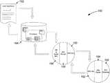
- FIG. 1displays a block representation of an example automation system 100 that can operate in accordance with assorted embodiments to optimize the development and testing of automation control.
- the automation system 100can utilize any number of automated devices 102 independently or concurrently to carry out a diverse variety of tasks, such as manufacturing, construction, down-hole exploration, and testing. It is contemplated that the system 100 may have multiple different automated devices 102 that may be physically separated, or interconnected, to carry out one or more tasks.
- An automated device 102may be any assembly of parts capable of translating computer readable code into motion without direct physical or logical manipulation by a user. Hence, the automated device 102 is configured to operate autonomously as directed by pre-programmed instructions without involvement by a user.
- each automated device 102can be connected to a computing device 104 via a wired or wireless connection.
- the computing device 104can be stationary, such as a desktop computer, or mobile, such as a laptop, tablet computer, or smartphone.
- the computing device 104can conduct a variety of different computing activities, such as data generation, manipulation, storage, and transmission, via one or more local processing components.
- the computing device 104can receive physical input from a user, process the input into computer readable code, such as machine code, and transmit that code to the automated device(s) 102 .
- the computing device 104can utilize a wired or wireless network 106 connection to engage one or more remote hosts 108 and 110 .
- the remote hosts 108 and 110can provide additional processing, data storage, and connectivity that can concurrently or independently complement the capabilities of the computing device 104 to make control of the automated device(s) 102 more efficient.
- the first host 108may be a remote server that provides additional data storage capacity while the second host 110 is a network node that can utilize additional computing capabilities from one or more devices physically separated from the computing device 104 .
- FIG. 2conveys an example automated device 120 that can be constructed and operated as part of the automation system 100 of FIG. 1 in accordance with some embodiments.
- An automated device 120may have one or more means for motion that can concurrently, or independently, induce activity in at least one component of the device 120 .
- a motor and solenoidmay concurrently articulate an arm while an engine supplies hydraulic and/or pneumatic pressure to be used by the arm at a later time.
- the automated device 120can have any number of components that move, spin, and grasp as orchestrated by a predetermined choreographed automation process and carried out by the means for motion that can be physically located on, or separated from, the automated device 120 itself.
- the automated device 120is adapted to provide computing capabilities with at least one local controller 122 , such as a microprocessor or application specific integrated circuit (ASIC), that is physically located on/in the automated device 120 .
- the controller 122can direct data into, and out of, a local memory 124 , which may be a volatile or non-volatile memory, such as a hard disk drive, solid-state memory array, or hybrid data storage device.
- the temporary, or permanent, storage of data in the local memory 124allows the automated device 120 to conduct various operations without being connected to a control device, such as the computing device 104 of FIG. 1 .
- the automated device 120can employ one or more sensors 126 that can continuously, routinely, or sporadically activate to monitor operational and environmental conditions in and around various portions of the automated device 120 .
- a temperature sensorcan operate continuously while a proximity sensor is sporadically activated when a portion of the automated device 120 is within a predetermined physical tolerance with an object.
- datacan be locally stored in the memory 124 and processed by the controller 122 , which allows increased autonomy compared to devices that do not have local computing capabilities.
- the automated device 120can generate, store, and process data locally, various embodiments connect the device 120 with at least one remote host, such as the computing device 104 or hosts 108 / 110 of FIG. 1 , via a communication module 128 .
- the communication module 128can utilize one or more different types of communication means to transfer data, such as cellular, wireless local network, and wired connection protocol. It is contemplated that the automated device 120 employs redundant communication means via the communication module 128 to ensure the device 120 is in constant communication with a remote host.
- the automated device 120may employ a de-parser module 130 to convert parsed automation information into automation code that corresponds with the automation process desired by a user.
- the de-parser module 130can utilize the controller 122 and non-volatile memory 124 to store and process received broadcast parameters into automation code that results in an automation process being executed by the device 120 .
- the ability to de-parse transmitted communications locally in the automated device 120instead of at the computing device 102 where an automation process was created, allows the broadcast parameters to be logically smaller and more efficiently transmitted compared to if the entire automation process computer code was transmitted.
- FIG. 3shows a block representation of an example computing device 140 that can be incorporated in the automation system 100 in accordance with assorted embodiments.
- the computing device 140can be used continuously, but in some embodiments is utilized during design, testing, and implementation of an automation process that is stored locally in one or more automated devices.
- the computing device 140has at least one local controller 142 that directs data processing entered by a user via a graphical user interface (GUI) 144 .
- GUIgraphical user interface
- a useris to be understood as a human operator that engages the GUI 144 to generate, or manipulate, data that is temporarily and permanently stored locally in a memory 146 .
- Various embodimentshave software stored in the local memory 146 that can be utilized to model and program an automation process as directed by the user.
- the local controller 142may provide a graphical representation of an automation process via the GUI 144 .
- the computing device 140allows a user to visually model an automation process without manually inserting lines of computer or machine code. That is, the computing power and capabilities of the computing device 140 can allow existing, or future, movement, actions, and processes of one or more automated devices 120 to be visually generated and manipulated without the user actually typing lines of code.
- Such visual modeling capabilitycan be highly efficient as the computing power of the computing device 140 converts visual models from the GUI 144 into lines of computer/machine code via a code module 148 .
- the code module 148may operate as part of a database of code that has been predetermined. However, the code module 148 may also generate new code that is inserted into the database, or updates existing code stored in the database.
- a parser module 150 of the computing device 140can condense or translate portions of code into parameters that are essential for transmission to an automated device 120 .
- parsing of an automation processwas limited to parameters that conform to communication protocol dictated by a third party.
- the full range of capabilities of an automated device 120may not be able to be utilized.
- development of open source communication protocolsuch as open platform communications-unified architecture (OPC-UA) has allowed machine code to be transmitted between computing 140 and automated 120 devices via a communication module 152 as dictated by the computing device 140 .
- OPC-UAopen platform communications-unified architecture
- open source communication protocolto transmit machine code and/or automation process parameters allows a diverse variety of automation control to be sent to an automated device 120 .
- the increased control provided by the open source communication protocolhas corresponded with larger development and testing schedules that are expensive in terms of time and resources.
- various embodimentsconfigure the parser module 150 to efficiently transition between a visual model present on the GUI 144 to condense machine code from a local database that forms an automation process into broadcast parameters that can efficiently be transmitted to, processed by, and executed by the automated device 120 .
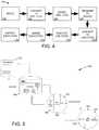
- FIG. 4depicts a logical flow for an example automation system 160 that utilizes the computing device 140 of FIG. 3 to optimize the transition from modeled and coded automation process to executed device activity.
- an automation processbegins with a model in step 162 , which may be created or manipulated completely by a human user on a computing device 140 .
- the computing device 140automatically converts the modeled automation process into a plurality of computer code (line code) as part of a database in step 164 .
- the computer codeis then parsed in step 166 by a parser module into broadcast parameters that are logically smaller than the entire coded automation process and are more quickly transmitted to one or more automated devices in step 168 .
- the broadcast parametersreplace the entirety of the computer coded automation process with a more lightweight package that can be transmitted to the automation device(s) more efficiently.
- the broadcast parametersalso are more efficiently processed back into the computer code by a de-parser module of the automated device 120 in step 170 compared to if the entirety of the code was transmitted or if a non-open source communication protocol limited the broadcast parameters.
- the processis executed in step 172 as part of a choreographed routine.
- the executionmay be sensed in step 174 by one or more sensors in and around the automated device to verify the accurate and complete performance of the automation process.
- the sensed conditionsare subsequently reported in 176 to a remote host, such as the computing device 140 .
- a remote hostsuch as the computing device 140 .
- FIG. 5is an example automation system 180 that can utilize the various aspects of FIGS. 1-4 to provide optimized device automation in accordance with some embodiments.
- a user interface 182is employed by a user to create a complete automation process that is then converted to a database 184 of code, which may be multiple lines of computer and/or machine code.
- a code module 186translates the database code into a readable format, such as XML code.
- a parser module 188proceeds to compile the XML code into a group of broadcast parameters that are transmitted to an automated device via a communication module 190 as an open source protocol (OPC-UA).
- a communication module 192 of the automated devicereceives the broadcast parameters as part of the open source protocol and then de-parses the broadcast parameters into XML code. It is noted that the XML code from the de-parser module of the automated device matches the XML code from the code module 186 and fully represents the automation process modeled in the user interface 182 . Next, the XML code is executed via an electronic gateway, such as a PLC gateway.
- FIG. 6provides a flowchart of an example automation routine 200 that can be carried out by the automation system and components of FIGS. 1-5 in accordance with assorted embodiments.
- the routine 200may begin by wirelessly, and or via a wired pathway, connecting at least one automated device to a computing device.
- a usermodels an automation process with a GUI of the computing device.
- the modeling of step 202may be code-based, visual-based, or a combination of the two.
- the modeled automation processis then compiled by a code module of the computing device in step 204 into a computer code, which can be characterized as synonymous with machine code.
- the computer/machine codecan be locally stored or referenced with a database to previous automation code, but such is not required.
- a parser module of the computing deviceproceeds to parse the computer code into broadcast parameters in step 206 .
- the broadcast parametersmay consist of any number and type of data that conforms to an open source communication protocol, such as OPC-UA. It is contemplated that the broadcast parameters are logically smaller and contain less data than the automation process as a whole, or the computer code compiled in step 204 .
- the parsing of the computer/machine code into previously defined broadcast parameters conforming to open source communication protocolallows efficient transmission to one or more automation devices in step 208 and conversion into automation code in step 210 by each automation device. If the parser module did not intelligently condense the computer code into broadcast parameters, the transmission and conversion to automation code would be sub-optimal and may hamper the development and testing of the automation process modeled in step 202 .
- the automation codemay be different than the computer code, such as by being a different type of machine code, but the result of execution of either the computer code, in its entirety by a computer, or the automation code by the automated device in step 212 will be the same.
- the execution of the automation code to perform the modeled automation processcycles routine 200 back to step 202 while other embodiments proceeds to sense the executed automation process activity in step 214 either during or after step 212 .
- Step 214may activate one or more different types of sensors to determine if the automation process has been, or is being, executed correctly, which is evaluated in decision 216 . If the sensed execution is correct, step 218 triggers the next activity to be performed, such as a subsequent event, motion, or series of actions called for by the automation process. That is, an automation process may be broken up into phases or activities that can be executed and sensed as correct in decision 216 prior to proceeding.
Landscapes
- Engineering & Computer Science (AREA)
- Physics & Mathematics (AREA)
- General Physics & Mathematics (AREA)
- Automation & Control Theory (AREA)
- General Engineering & Computer Science (AREA)
- Computer Networks & Wireless Communication (AREA)
- Signal Processing (AREA)
- Manufacturing & Machinery (AREA)
- Theoretical Computer Science (AREA)
- Quality & Reliability (AREA)
- Human Computer Interaction (AREA)
- Programmable Controllers (AREA)
Abstract
Description
Claims (20)
Priority Applications (4)
| Application Number | Priority Date | Filing Date | Title |
|---|---|---|---|
| US15/879,683US10983511B2 (en) | 2017-02-14 | 2018-01-25 | Automation control system |
| EP19744192.6AEP3743817A4 (en) | 2017-02-14 | 2019-01-18 | AUTOMATION CONTROL SYSTEM |
| PCT/US2019/014186WO2019147491A1 (en) | 2017-02-14 | 2019-01-18 | Automation control system |
| CN201980013802.7ACN112204531B (en) | 2017-02-14 | 2019-01-18 | Automation control system |
Applications Claiming Priority (2)
| Application Number | Priority Date | Filing Date | Title |
|---|---|---|---|
| US201762458852P | 2017-02-14 | 2017-02-14 | |
| US15/879,683US10983511B2 (en) | 2017-02-14 | 2018-01-25 | Automation control system |
Publications (2)
| Publication Number | Publication Date |
|---|---|
| US20180231963A1 US20180231963A1 (en) | 2018-08-16 |
| US10983511B2true US10983511B2 (en) | 2021-04-20 |
Family
ID=63106316
Family Applications (1)
| Application Number | Title | Priority Date | Filing Date |
|---|---|---|---|
| US15/879,683Active2038-06-13US10983511B2 (en) | 2017-02-14 | 2018-01-25 | Automation control system |
Country Status (4)
| Country | Link |
|---|---|
| US (1) | US10983511B2 (en) |
| EP (1) | EP3743817A4 (en) |
| CN (1) | CN112204531B (en) |
| WO (1) | WO2019147491A1 (en) |
Citations (14)
| Publication number | Priority date | Publication date | Assignee | Title |
|---|---|---|---|---|
| US6668354B1 (en) | 1999-01-05 | 2003-12-23 | International Business Machines Corporation | Automatic display script and style sheet generation |
| US20050188351A1 (en) | 2002-04-02 | 2005-08-25 | Siemens Aktiengesellschaft | Device and method for automatically generating automation software |
| US7313564B2 (en) | 2002-12-03 | 2007-12-25 | Symbioware, Inc. | Web-interactive software testing management method and computer system including an integrated test case authoring tool |
| US20090210814A1 (en)* | 2007-10-01 | 2009-08-20 | Agrusa Russell L | Visualization of process control data |
| US7706895B2 (en) | 2005-02-25 | 2010-04-27 | Rockwell Automation Technologies, Inc. | Reliable messaging instruction |
| US20110022192A1 (en)* | 2006-09-29 | 2011-01-27 | Rockwell Automation Technologies, Inc. | Management and development of an industrial environment |
| US20110093800A1 (en) | 2006-06-29 | 2011-04-21 | Rockwell Automation Technologies, Inc. | Hmi framework for extensible automation system engineering platforms |
| US20120158165A1 (en)* | 2009-08-31 | 2012-06-21 | Siemens Aktiengesellschaft | Workflow Centered Mechatronic Objects |
| US8244774B2 (en) | 2004-05-21 | 2012-08-14 | Ca, Inc. | Automated creation of web GUI for XML servers |
| US8402434B2 (en) | 2003-12-29 | 2013-03-19 | International Business Machines Corporation | Graphical user interface (GUI) script generation and documentation |
| US20130231787A1 (en)* | 2012-03-02 | 2013-09-05 | Clinton D. Chapman | Dynamic phase machine automation of oil & gas processes |
| US8751629B2 (en) | 2008-06-18 | 2014-06-10 | Camber Defense Security And Systems Solutions, Inc. | Systems and methods for automated building of a simulated network environment |
| US20160055140A1 (en)* | 2014-08-25 | 2016-02-25 | Purple Robot Software, Inc. | Peer to peer spreadsheet processing |
| US9348564B2 (en) | 2009-07-23 | 2016-05-24 | Rockwell Automation Technologies, Inc. | Intelligent device framework |
Family Cites Families (5)
| Publication number | Priority date | Publication date | Assignee | Title |
|---|---|---|---|---|
| CN101208660A (en)* | 2005-06-27 | 2008-06-25 | 奎朴兹有限公司 | Transcoding |
| CN102246108B (en)* | 2009-04-17 | 2015-04-22 | 西门子公司 | Monitoring an automation system |
| US20140286406A1 (en)* | 2011-11-08 | 2014-09-25 | Samsung Electronics Co., Ltd. | Method for determining quantization parameters on basis of size of conversion block, and device for same |
| CN104484166B (en)* | 2014-12-04 | 2017-07-28 | 山东科技大学 | A kind of automatization test system mathematics library device and method |
| CN107835964B (en)* | 2015-06-24 | 2020-09-11 | 西门子公司 | Control contextualization and reasoning about controls |
- 2018
- 2018-01-25USUS15/879,683patent/US10983511B2/enactiveActive
- 2019
- 2019-01-18WOPCT/US2019/014186patent/WO2019147491A1/ennot_activeCeased
- 2019-01-18CNCN201980013802.7Apatent/CN112204531B/enactiveActive
- 2019-01-18EPEP19744192.6Apatent/EP3743817A4/ennot_activeCeased
Patent Citations (14)
| Publication number | Priority date | Publication date | Assignee | Title |
|---|---|---|---|---|
| US6668354B1 (en) | 1999-01-05 | 2003-12-23 | International Business Machines Corporation | Automatic display script and style sheet generation |
| US20050188351A1 (en) | 2002-04-02 | 2005-08-25 | Siemens Aktiengesellschaft | Device and method for automatically generating automation software |
| US7313564B2 (en) | 2002-12-03 | 2007-12-25 | Symbioware, Inc. | Web-interactive software testing management method and computer system including an integrated test case authoring tool |
| US8402434B2 (en) | 2003-12-29 | 2013-03-19 | International Business Machines Corporation | Graphical user interface (GUI) script generation and documentation |
| US8244774B2 (en) | 2004-05-21 | 2012-08-14 | Ca, Inc. | Automated creation of web GUI for XML servers |
| US7706895B2 (en) | 2005-02-25 | 2010-04-27 | Rockwell Automation Technologies, Inc. | Reliable messaging instruction |
| US20110093800A1 (en) | 2006-06-29 | 2011-04-21 | Rockwell Automation Technologies, Inc. | Hmi framework for extensible automation system engineering platforms |
| US20110022192A1 (en)* | 2006-09-29 | 2011-01-27 | Rockwell Automation Technologies, Inc. | Management and development of an industrial environment |
| US20090210814A1 (en)* | 2007-10-01 | 2009-08-20 | Agrusa Russell L | Visualization of process control data |
| US8751629B2 (en) | 2008-06-18 | 2014-06-10 | Camber Defense Security And Systems Solutions, Inc. | Systems and methods for automated building of a simulated network environment |
| US9348564B2 (en) | 2009-07-23 | 2016-05-24 | Rockwell Automation Technologies, Inc. | Intelligent device framework |
| US20120158165A1 (en)* | 2009-08-31 | 2012-06-21 | Siemens Aktiengesellschaft | Workflow Centered Mechatronic Objects |
| US20130231787A1 (en)* | 2012-03-02 | 2013-09-05 | Clinton D. Chapman | Dynamic phase machine automation of oil & gas processes |
| US20160055140A1 (en)* | 2014-08-25 | 2016-02-25 | Purple Robot Software, Inc. | Peer to peer spreadsheet processing |
Also Published As
| Publication number | Publication date |
|---|---|
| CN112204531A (en) | 2021-01-08 |
| EP3743817A4 (en) | 2021-09-22 |
| US20180231963A1 (en) | 2018-08-16 |
| EP3743817A1 (en) | 2020-12-02 |
| CN112204531B (en) | 2024-12-20 |
| WO2019147491A1 (en) | 2019-08-01 |
Similar Documents
| Publication | Publication Date | Title |
|---|---|---|
| CN107168754B (en) | System and method relating to multi-module compilation | |
| US9124999B2 (en) | Method and apparatus for wireless communications in a process control or monitoring environment | |
| CN114787838A (en) | Software defined manufacturing/assembly system | |
| US20180178380A1 (en) | Method for extending end user programming of an industrial robot with third party contributions | |
| US8543370B2 (en) | Multiple PLC simulation system | |
| US8862251B2 (en) | Controller for machine tool and machining-related data processing system provided therewith | |
| CN106104467A (en) | A kind of Automation arranging method and terminal | |
| EP2466404A1 (en) | Method for controlling industrial robots in a work area | |
| KR20180118474A (en) | Flexible assembly system for multi-product production and method of reconstructing a production line | |
| WO2008075631A1 (en) | Plc dispersion control system | |
| CN204287908U (en) | Flow computer | |
| US20250155856A1 (en) | Industrial control code generation utilizing functional design specifications | |
| CN113454551A (en) | Automated code generator for interoperability between industrial ecosystems | |
| KR101323937B1 (en) | A simulation system of communication between HMI simulator and PLC simulator | |
| US10983511B2 (en) | Automation control system | |
| US10605570B2 (en) | Method and apparatus for launch control packet processing | |
| KR20170093562A (en) | Smart factory connection module and operating method thereof | |
| CN104331024B (en) | Autocontrol method and the digital control system in open type based on PC | |
| US11218360B2 (en) | Automation system with edge computing | |
| CN105227407A (en) | A kind of protocol debugging method, Apparatus and system | |
| KR20230118302A (en) | Method and Apparatus for Virtual Environment Creating of Smart Factory | |
| JP7044086B2 (en) | Control systems, control methods, and control programs | |
| KR102302303B1 (en) | Method for control of multiple transfer units | |
| KR101888792B1 (en) | Method for data communication and system comprising the same | |
| Makris | An Approach for Validating the Behavior of Autonomous Robots in a Virtual Environment |
Legal Events
| Date | Code | Title | Description |
|---|---|---|---|
| AS | Assignment | Owner name:QUEST AUTOMATED SERVICES, LLC, OKLAHOMA Free format text:ASSIGNMENT OF ASSIGNORS INTEREST;ASSIGNORS:DA SILVA, HANZ;MARTELL, EDWARD;SIGNING DATES FROM 20180112 TO 20180122;REEL/FRAME:044727/0028 | |
| FEPP | Fee payment procedure | Free format text:ENTITY STATUS SET TO UNDISCOUNTED (ORIGINAL EVENT CODE: BIG.); ENTITY STATUS OF PATENT OWNER: SMALL ENTITY | |
| FEPP | Fee payment procedure | Free format text:ENTITY STATUS SET TO SMALL (ORIGINAL EVENT CODE: SMAL); ENTITY STATUS OF PATENT OWNER: SMALL ENTITY | |
| STPP | Information on status: patent application and granting procedure in general | Free format text:DOCKETED NEW CASE - READY FOR EXAMINATION | |
| STPP | Information on status: patent application and granting procedure in general | Free format text:NON FINAL ACTION MAILED | |
| STPP | Information on status: patent application and granting procedure in general | Free format text:FINAL REJECTION MAILED | |
| STPP | Information on status: patent application and granting procedure in general | Free format text:NON FINAL ACTION MAILED | |
| AS | Assignment | Owner name:ERNEST W. MOODY REVOCABLE TRUST, NEVADA Free format text:SECURITY INTEREST;ASSIGNOR:QUEST AUTOMATED SERVICES, LLC;REEL/FRAME:054671/0882 Effective date:20201216 | |
| STPP | Information on status: patent application and granting procedure in general | Free format text:NOTICE OF ALLOWANCE MAILED -- APPLICATION RECEIVED IN OFFICE OF PUBLICATIONS | |
| STPP | Information on status: patent application and granting procedure in general | Free format text:PUBLICATIONS -- ISSUE FEE PAYMENT RECEIVED | |
| STPP | Information on status: patent application and granting procedure in general | Free format text:PUBLICATIONS -- ISSUE FEE PAYMENT VERIFIED | |
| STCF | Information on status: patent grant | Free format text:PATENTED CASE | |
| MAFP | Maintenance fee payment | Free format text:PAYMENT OF MAINTENANCE FEE, 4TH YR, SMALL ENTITY (ORIGINAL EVENT CODE: M2551); ENTITY STATUS OF PATENT OWNER: SMALL ENTITY Year of fee payment:4 |