US10982439B2 - Dry floor liquid disposal system - Google Patents
Dry floor liquid disposal systemDownload PDFInfo
- Publication number
- US10982439B2 US10982439B2US16/175,337US201816175337AUS10982439B2US 10982439 B2US10982439 B2US 10982439B2US 201816175337 AUS201816175337 AUS 201816175337AUS 10982439 B2US10982439 B2US 10982439B2
- Authority
- US
- United States
- Prior art keywords
- grid
- pan
- openings
- members
- floor assembly
- Prior art date
- Legal status (The legal status is an assumption and is not a legal conclusion. Google has not performed a legal analysis and makes no representation as to the accuracy of the status listed.)
- Active, expires
Links
- 239000007788liquidSubstances0.000titleclaimsabstractdescription55
- 230000002745absorbentEffects0.000claimsdescription27
- 239000002250absorbentSubstances0.000claimsdescription27
- 238000000034methodMethods0.000claimsdescription24
- 239000000463materialSubstances0.000claimsdescription14
- 239000012530fluidSubstances0.000claimsdescription8
- 239000007769metal materialSubstances0.000claimsdescription8
- 239000011248coating agentSubstances0.000claimsdescription6
- 238000000576coating methodMethods0.000claimsdescription6
- 230000002209hydrophobic effectEffects0.000claimsdescription5
- 238000004891communicationMethods0.000claimsdescription4
- 238000005266castingMethods0.000claims1
- 239000011152fibreglassSubstances0.000description11
- 230000000712assemblyEffects0.000description7
- 238000000429assemblyMethods0.000description7
- 239000001913celluloseSubstances0.000description4
- 229920002678cellulosePolymers0.000description4
- 230000010006flightEffects0.000description4
- 238000007688edgingMethods0.000description3
- 239000007787solidSubstances0.000description3
- XLYOFNOQVPJJNP-UHFFFAOYSA-NwaterSubstancesOXLYOFNOQVPJJNP-UHFFFAOYSA-N0.000description3
- OKTJSMMVPCPJKN-UHFFFAOYSA-NCarbonChemical compound[C]OKTJSMMVPCPJKN-UHFFFAOYSA-N0.000description2
- 239000000853adhesiveSubstances0.000description2
- 230000001070adhesive effectEffects0.000description2
- 238000004140cleaningMethods0.000description2
- 239000010439graphiteSubstances0.000description2
- 229910002804graphiteInorganic materials0.000description2
- 238000012423maintenanceMethods0.000description2
- 239000003381stabilizerSubstances0.000description2
- 230000007704transitionEffects0.000description2
- JOYRKODLDBILNP-UHFFFAOYSA-NEthyl urethaneChemical compoundCCOC(N)=OJOYRKODLDBILNP-UHFFFAOYSA-N0.000description1
- 229910000831SteelInorganic materials0.000description1
- 238000009825accumulationMethods0.000description1
- 230000001010compromised effectEffects0.000description1
- 230000000694effectsEffects0.000description1
- 238000009408flooringMethods0.000description1
- 230000006870functionEffects0.000description1
- 238000009413insulationMethods0.000description1
- 230000003137locomotive effectEffects0.000description1
- 238000012986modificationMethods0.000description1
- 230000004048modificationEffects0.000description1
- 230000037361pathwayEffects0.000description1
- 238000011176poolingMethods0.000description1
- 239000001488sodium phosphateSubstances0.000description1
- 229910000162sodium phosphateInorganic materials0.000description1
- 239000010959steelSubstances0.000description1
- 230000000153supplemental effectEffects0.000description1
- 239000004634thermosetting polymerSubstances0.000description1
- RYFMWSXOAZQYPI-UHFFFAOYSA-Ktrisodium phosphateChemical compound[Na+].[Na+].[Na+].[O-]P([O-])([O-])=ORYFMWSXOAZQYPI-UHFFFAOYSA-K0.000description1
- 239000011800void materialSubstances0.000description1
Images


Classifications
- E—FIXED CONSTRUCTIONS
- E04—BUILDING
- E04B—GENERAL BUILDING CONSTRUCTIONS; WALLS, e.g. PARTITIONS; ROOFS; FLOORS; CEILINGS; INSULATION OR OTHER PROTECTION OF BUILDINGS
- E04B5/00—Floors; Floor construction with regard to insulation; Connections specially adapted therefor
- E04B5/48—Special adaptations of floors for incorporating ducts, e.g. for heating or ventilating
- B—PERFORMING OPERATIONS; TRANSPORTING
- B64—AIRCRAFT; AVIATION; COSMONAUTICS
- B64C—AEROPLANES; HELICOPTERS
- B64C1/00—Fuselages; Constructional features common to fuselages, wings, stabilising surfaces or the like
- B64C1/18—Floors
- E—FIXED CONSTRUCTIONS
- E04—BUILDING
- E04F—FINISHING WORK ON BUILDINGS, e.g. STAIRS, FLOORS
- E04F15/00—Flooring
- E04F15/02—Flooring or floor layers composed of a number of similar elements
- E04F15/02172—Floor elements with an anti-skid main surface, other than with grooves
- A—HUMAN NECESSITIES
- A47—FURNITURE; DOMESTIC ARTICLES OR APPLIANCES; COFFEE MILLS; SPICE MILLS; SUCTION CLEANERS IN GENERAL
- A47G—HOUSEHOLD OR TABLE EQUIPMENT
- A47G27/00—Floor fabrics; Fastenings therefor
- A47G27/02—Carpets; Stair runners; Bedside rugs; Foot mats
- A47G27/0212—Carpets; Stair runners; Bedside rugs; Foot mats to support or cushion
- A47G27/0225—Carpets; Stair runners; Bedside rugs; Foot mats to support or cushion for bathrooms
- B—PERFORMING OPERATIONS; TRANSPORTING
- B32—LAYERED PRODUCTS
- B32B—LAYERED PRODUCTS, i.e. PRODUCTS BUILT-UP OF STRATA OF FLAT OR NON-FLAT, e.g. CELLULAR OR HONEYCOMB, FORM
- B32B17/00—Layered products essentially comprising sheet glass, or glass, slag, or like fibres
- B32B17/06—Layered products essentially comprising sheet glass, or glass, slag, or like fibres comprising glass as the main or only constituent of a layer, next to another layer of a specific material
- B—PERFORMING OPERATIONS; TRANSPORTING
- B32—LAYERED PRODUCTS
- B32B—LAYERED PRODUCTS, i.e. PRODUCTS BUILT-UP OF STRATA OF FLAT OR NON-FLAT, e.g. CELLULAR OR HONEYCOMB, FORM
- B32B5/00—Layered products characterised by the non- homogeneity or physical structure, i.e. comprising a fibrous, filamentary, particulate or foam layer; Layered products characterised by having a layer differing constitutionally or physically in different parts
- B32B5/02—Layered products characterised by the non- homogeneity or physical structure, i.e. comprising a fibrous, filamentary, particulate or foam layer; Layered products characterised by having a layer differing constitutionally or physically in different parts characterised by structural features of a fibrous or filamentary layer
- B—PERFORMING OPERATIONS; TRANSPORTING
- B64—AIRCRAFT; AVIATION; COSMONAUTICS
- B64D—EQUIPMENT FOR FITTING IN OR TO AIRCRAFT; FLIGHT SUITS; PARACHUTES; ARRANGEMENT OR MOUNTING OF POWER PLANTS OR PROPULSION TRANSMISSIONS IN AIRCRAFT
- B64D11/00—Passenger or crew accommodation; Flight-deck installations not otherwise provided for
- B64D11/02—Toilet fittings
- E—FIXED CONSTRUCTIONS
- E04—BUILDING
- E04F—FINISHING WORK ON BUILDINGS, e.g. STAIRS, FLOORS
- E04F15/00—Flooring
- E04F15/18—Separately-laid insulating layers; Other additional insulating measures; Floating floors
- B—PERFORMING OPERATIONS; TRANSPORTING
- B32—LAYERED PRODUCTS
- B32B—LAYERED PRODUCTS, i.e. PRODUCTS BUILT-UP OF STRATA OF FLAT OR NON-FLAT, e.g. CELLULAR OR HONEYCOMB, FORM
- B32B2307/00—Properties of the layers or laminate
- B32B2307/70—Other properties
- B32B2307/726—Permeability to liquids, absorption
- B—PERFORMING OPERATIONS; TRANSPORTING
- B64—AIRCRAFT; AVIATION; COSMONAUTICS
- B64C—AEROPLANES; HELICOPTERS
- B64C2211/00—Modular constructions of airplanes or helicopters
Definitions
- Embodiments of the present disclosuregenerally relate to systems and methods for providing a floor for collection and/or removal of liquid, such as a lavatory floor within a commercial aircraft.
- floorsmay be subject to spillage or leakage of liquids. It may not be possible or practical to manually remove the liquid from the floor in as short a time as may be desired.
- commercial aircraftare used to transport passengers between various locations. During a flight—particularly a trans-oceanic or other long haul flight—passengers are typically confined within certain areas (for example, cabins) of an aircraft.
- Various individuals(such as passengers, pilots, flight attendants, and the like) use certain internal portions of an aircraft during a flight. For example, numerous individuals may use a lavatory within an internal cabin during a flight. Liquid (e.g., from the sink) may be spilled to the lavatory floor.
- An aircraft lavatoryis generally cleaned between flights. For example, maintenance or cleaning personnel board the aircraft on the ground before and/or after a flight to clean the lavatory.
- the lavatoryis typically not cleaned, despite the fact that numerous individuals may use the lavatory during the flight. While flight attendants may be able to clean the lavatory, they are usually preoccupied with other duties during the flight. As such, cleaning the lavatory may not be a top priority for flight attendants during a flight or even between flights. Consequently, the dryness of lavatory floors onboard an aircraft may be compromised, particularly during flights. As such, a flight experience for individuals onboard the aircraft may be negatively impacted.
- the dry floor assemblyis configured to form or be positioned on a floor of an enclosed space.
- the dry floor assemblyincludes a grid, a pan, and a wicking layer.
- the gridhas an array of openings configured to allow passage of liquid.
- the gridhas members that extend from a base to an upper surface, with the upper surface configured to be walked upon. The members have a cross-section that tapers from the base to the upper surface.
- the panis disposed beneath the grid, and defines a cavity.
- the wicking layeris interposed between the pan and the grid, and is configured to wick liquid that passes through the openings toward the pan.
- Certain embodiments of the present disclosureprovide a method for providing a dry floor assembly that is configured to form or be positioned on a floor of an enclosed space.
- the methodincludes providing a grid having an array of openings configured to allow passage of liquid.
- the gridhas members extending from a base to an upper surface, with the upper surface configured to be walked upon.
- the membershave a cross-section that tapers from the base to the upper surface.
- the methodalso includes disposing a pan beneath the grid.
- the pandefines a cavity.
- the methodincludes providing a wicking layer interposed between the pan and the grid. The wicking layer is configured to wick liquid that passes through the openings of the grid toward the pan.
- an absorbent pad(e.g., for use with a dry floor assembly).
- the absorbent padincludes an absorbent core portion, a wicking portion, and a fiberglass outer play.
- the wicking portionsurrounds the absorbent core.
- the fiberglass outerply surrounds the wicking portion and defines an exterior of the absorbent pad.
- FIG. 1illustrates a perspective top view of an aircraft, according to an embodiment of the present disclosure.
- FIG. 2Aillustrates a top plan view of an internal cabin of an aircraft, according to an embodiment of the present disclosure.
- FIG. 2Billustrates a top plan view of an internal cabin of an aircraft, according to an embodiment of the present disclosure.
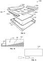
- FIG. 3illustrates an exploded side sectional view of a dry floor assembly, according to an embodiment of the present disclosure.
- FIG. 4provides a plan view of s grid 110 of the dry floor assembly of FIG. 3 .
- FIG. 5provides a cross-section of a member of the grid of FIG. 4 .
- FIG. 6provides an exploded side view of an example wicking layer, according to an embodiment of the present disclosure.
- FIG. 7provides a plan view of the example wicking layer of FIG. 6 .
- FIG. 8provides a plan view of a support layer of the assembly of FIG. 3 .
- FIG. 9illustrates an exploded perspective view of a system that includes surround members, according to an embodiment of the present disclosure.
- FIG. 10provides a side view of a pan with a reservoir, according to an embodiment of the present disclosure.
- FIG. 11provides a side view of a pan with an articulable reservoir, according to an embodiment of the present disclosure.
- FIG. 12provides a schematic view of an absorbent pad, according to an embodiment of the present disclosure.
- FIG. 13illustrates a flow chart of a method for providing a dry floor assembly, according to an embodiment of the present disclosure.
- Embodiments of the present disclosureprovide systems, methods, and assemblies for providing a dry floor, such as a lavatory floor.
- the systems, methods, and assembliesmay be used in various settings, such as within a lavatory of a vehicle, a public washroom in a building, a laboratory, and/or the like.
- Examples of vehicles for various embodimentsinclude aircraft, ships, or ground-based vehicles such as buses or trains.
- Various embodiments of the present disclosureprovide a dry floor assembly for removing liquids from a floor or walking surface.
- Various embodimentsprovide a multilayer system to reduce or eliminate liquid pooling, with the top layer staying dry to the touch, and a lower layer pulling liquid from the top layer.
- Various embodimentsprovide for the removal of liquids from a floor. Further, various embodiments provide easily replaceable components that are seamlessly interfaced to existing infrastructure (e.g., aircraft infrastructure).
- existing infrastructuree.g., aircraft infrastructure
- FIG. 1illustrates a perspective top view of an aircraft 10 , according to an embodiment of the present disclosure.
- the aircraft 10may include a propulsion system 12 that may include two turbofan engines 14 , for example.
- the propulsion system 12may include more engines 14 than shown.
- the engines 14are carried by wings 16 of the aircraft 10 .
- the engines 14may be carried by a fuselage 18 and/or an empennage 20 .
- the empennage 20may also support horizontal stabilizers 22 and a vertical stabilizer 24 . While various embodiments are discussed in connection with aircraft, it may be again noted that other embodiments may be utilized in connection with, for example, other vehicle, such as ships, or ground-based vehicles such as buses or trains.
- the fuselage 18 of the aircraft 10defines an internal cabin, which may include a cockpit, one or more work sections (for example, galleys, personnel carry-on baggage areas, and the like), one or more passenger sections (for example, first class, business class, and coach sections), and an aft section in which an aft rest area assembly may be positioned.
- Each of the sectionsmay be separated by a cabin transition area, which may include one or more class divider assemblies.
- Overhead stowage bin assembliesmay be positioned throughout the internal cabin.
- the internal cabinincludes one or more lavatories, for example.
- Embodiments of the present disclosureprovide systems and methods that are configured to automatically dry floors within the lavatories.
- embodiments of the present disclosuremay be used with various other vehicles, such as automobiles, buses, locomotives and train cars, watercraft, spacecraft, and the like. Further, embodiments of the present disclosure may be used with respect to fixed structures, such as commercial and residential buildings. As an example, embodiments of the present disclosure may be used to automatically dry floors of lavatories, whether or not the lavatories are within vehicles.
- FIG. 2Aillustrates a top plan view of an internal cabin 30 of an aircraft, according to an embodiment of the present disclosure.
- the internal cabin 30may be within a fuselage 32 of the aircraft.
- one or more fuselage wallsmay define the internal cabin 30 .
- the internal cabin 30includes multiple sections, including a front section 33 , a first class section 34 (or first class suites, cabins, for example), a business class section 36 , a front galley station 38 , an expanded economy or coach section 40 , a standard economy or coach section 42 , and an aft section 44 , which may include multiple lavatories and galley stations.
- the internal cabin 30may include more or less sections than shown.
- the internal cabin 30may not include a first class section, and may include more or less galley stations than shown.
- Each of the sectionsmay be separated by a cabin transition area 46 , which may include class divider assemblies between aisles 48 .
- the internal cabin 30includes two aisles 50 and 52 that lead to the aft section 44 .
- the internal cabin 30may have less or more aisles than shown.
- the internal cabin 30may include a single aisle that extends through the center of the internal cabin 30 that leads to the aft section 44 .
- the lavatories 99may be located within the internal cabin 30 .
- the lavatories 99may include dry floor assemblies as discussed herein, which may be secured within a portion of the fuselage.
- the dry floor assembliesare configured to reduce or eliminate an amount of visible liquid on an exposed top surface.
- FIG. 2Billustrates a top plan view of an internal cabin 80 of an aircraft, according to an embodiment of the present disclosure.
- the internal cabin 80may be within a fuselage 81 of the aircraft.
- one or more fuselage wallsmay define the internal cabin 80 .
- the internal cabin 80includes multiple sections, including a main cabin 82 having passenger seats 83 , and an aft section 85 behind the main cabin 82 . It is to be understood that the internal cabin 80 may include more or less sections than shown.
- the internal cabin 80may include a single aisle 84 that leads to the aft section 85 .
- the single aisle 84may extend through the center of the internal cabin 80 that leads to the aft section 85 .
- the single aisle 84may be coaxially aligned with a central longitudinal plane of the internal cabin 80 .
- a dry floor assemblymay be located within a lavatory 99 of the main cabin 82 at a fore section 87 proximate to a cockpit area 89 . Additional lavatories 99 may be located throughout the main cabin 82 .
- FIG. 3illustrates an exploded side sectional view of a dry floor assembly 100 .
- the dry floor assembly 100 of the illustrated exampleincludes a grid 110 , a pan 130 , a wicking layer 140 , a support layer 150 , and an absorbent pad 180 .
- the dry floor assembly 100is configured to form a portion of a floor in an enclosed space (e.g., aircraft lavatory, ship lavatory, or lavatory of ground-based vehicles such as buses or trains), or to be positioned on or in a floor of an enclosed space.
- the grid 110provides a surface to be walked upon, and has openings through which liquid spilled on the walking surface passes.
- the wicking layer 140helps direct the liquid that has passed through the grid 110 toward the pan 130 .
- the pan 130is used to collect, store, and/or direct the liquid for disposal.
- the absorbent pad 180is disposed beneath the wicking layer 140 (e.g., within the pan 130 ) and used to absorb liquid passing through the grid 110 .
- the absorbent pad 180may be replaced after it has absorbed a predetermined amount of liquid and/or at a predetermined time interval.
- liquidmay be stored in the pan 130 and later removed (e.g., by vacuuming the pan 130 ).
- the pan 130may be used to direct liquid to a separate reservoir.
- the separate reservoirmay then collect the liquid for later removal, or alternatively an absorbent pad may be disposed in the separate reservoir. Accordingly, the water is directed away from the walking surface and toward a storage and collection area for subsequent removal, providing a clean, safe walking surface.
- various embodiments hereinare discussed in connection with use in commercial aircraft (e.g., in an aircraft lavatory). However, it may be noted that alternative embodiments may be used in other applications.
- FIG. 4provides a plan view of the grid 110
- FIG. 5provides a cross-section of a member of the grid 110
- the grid 110has an array 112 of openings 114 configured to allow passage of liquid.
- the grid 110has members 120 that extend from a base 122 to an upper surface 124 .
- the members 120have a cross-section 126 that tapers from the base 122 to the upper surface 124 .
- the taperingprovides a sloped surface that helps direct water away from the upper surface 124 and toward the base 122 (and pan 130 ).
- the members 120maintain the tapered shape at intersection points of the members 120 , helping to prevent beading or other accumulation of liquid at the intersection points of the members 120 .
- the gridmay be easily removable and replaced as necessary (e.g., due to wear).
- the members 120cross each other to define the openings 114 .
- the openings 114are sized to be smaller than a stiletto heel base to provide a safe, convenient walking surface while still allowing for drainage from the upper surface 124 .
- the members 120 of the illustrated embodimentsare substantially identical to each other dimensionally and in cross-section, however differently shaped members may be used in various embodiments.
- the grid 110 of the illustrated exampleprovides a uniformly spaced rectangular grid; however, other shapes or spacings may be used in other embodiments.
- the depicted exampleincludes a strip 116 that extends around a perimeter 117 of the grid 110 .
- the strip 116is bonded to the grid 110 . Additionally or alternatively, the strip 116 is bonded to the wicking layer 140 and/or the support layer 150 .
- the strip 116provides support to the grid 110 and may be used for mounting and/or positioning the grid 110 .
- the depicted pan 130includes a ledge 134 .
- the strip 116is made of a metallic material (e.g., steel), and may be secured to the ledge 134 (e.g., held in place on the ledge 134 ) via magnets 118 .
- the strip 116 and/or ledge 134 and associated magnetsmay also be used to mount additional structures (e.g., on top of the dry floor assembly 100 .
- additional structurese.g., on top of the dry floor assembly 100 .
- at least one surround member 160may be secured to the strip 116 via magnets.
- FIG. 9illustrates an exploded perspective view of a system 900 that includes the dry floor assembly 100 (e.g., pan 130 and grid 110 ). It may be noted that the support layer 150 and wicking layer 140 are not shown in FIG. 9 ; however, one or both may be utilized in various embodiments in connection with the aspects discussed in connection with FIG. 9 . As seen in FIG.
- the pan 130 and grid 110are configured to be placed in a floor pan 910 (e.g., a floor pan of a commercial aircraft).
- Various surround members 160are utilized, including an assist wall edging 160 a , a threshold edge 160 b , a sing wall edging 160 c , and a toilet edging 160 d .
- Each surround member 160includes one or more magnets 119 that are used to secure the corresponding surround member 160 to the strip 116 via magnetic attraction between the magnets 119 and the strip 116 and/or the magnets 119 of the surround member 160 and the magnets 118 of the ledge 134 of the pan 130 (e.g., the magnets 119 and magnets 118 may be aligned with each other and positioned with respective north and south poles oriented toward each other).
- the surround membersmay be used to allow use of a standardized grid size, with the surround members accommodating variations from the grid size in different environments (e.g., differently sized lavatories).
- the grid 110is formed of a non-flammable material.
- a non-flammable materialis a material that satisfies commercial aircraft non-flammability standards or regulations.
- the grid 110may be cast using a thermoset resin. As one example, 892 urethane may be used for forming the grid 110 .
- the grid 110in various embodiments has a hydrophobic coating, helping to urge water away from the grid 110 and toward the wicking layer 140 and pan 130 .
- the cross-section 126 of the members 120 of the grid 110defines an isosceles triangle 127 that tapers to a point 128 at the upper surface 124 .
- other shapesmay be employed in other embodiments.
- the illustrated exampleis symmetrical about a vertical axis passing through the point 128
- other embodimentsmay be asymmetrical about a vertical axis passing through the point 128 .
- the point 128may be at a lateral edge of the cross-section 126 instead of being centrally located as in the illustrated embodiment.
- all members 120have the same cross-section 126 ; however, in other embodiments at least some members 120 may utilize different cross-sections from others.
- the wicking layer 140is disposed beneath the grid 110 and interposed between the grid 110 and the pan 130 . It may be noted that, in the illustrated embodiment, the support layer 150 is interposed directly between the wicking layer 140 and the pan 130 . Generally, the wicking layer 140 is configured to wick liquid that passes through the openings 114 of the grid 110 toward the pan 130 . In various embodiments (e.g., for use in commercial aircraft) the wicking layer 140 may be made of one or more non-flammable materials. In some embodiments, a graphite veil (or felt) may be used in the wicking layer. Additionally or alternatively, fiberglass may be used in the wicking layer.
- the wicking layer 140may include two or more sub-layers.
- FIG. 6provides an exploded side view of an example wicking layer 140 with plural sublayers
- FIG. 7provides a plan view of the example wicking layer 140 .
- the depicted wicking layerincludes 4 sublayers 142 a , 142 b , 142 c , 142 d .
- the use of multiple relatively thin wicking layersprovides improved wicking from the grid 110 to the pan 130 .
- the wicking sub-layersmay be made of the same material, while in other embodiments the wicking sub-layers may be made of different materials from each other to provide a desired color and/or desired wicking performance.
- the sublayers 142 a , 142 bmay be made of a graphite veil while the sublayers 142 c , 142 d may be made of fiberglass.
- the wicking sub-layers in the illustrated embodimentare bonded (e.g., using adhesive) at discrete points to at least one of an adjacent sub-layer or the grid 110 .
- the uppermost sub-layeris bonded on one side to the base 122 of the grid 110 , and on the other side to the second uppermost sub-layer.
- the lower most sub-layeris bonded on its lowermost side to the support layer 150 , and on the other side to the second lower most sub-layer.
- the bondingis provided at discrete points 702 .
- the points 702may be arranged in an array 704 configured to align the points 702 with solid portions (e.g., the members 120 or intersection points of the members 120 ) of the grid 110 and solid portions of the support layer 150 .
- a tool or templatemay be used to apply adhesive at the points 702 to help insure accurate placement.
- Use of intermittent bonding points in various embodimentshelps the wicking sublayers to maintain uniform or near-uniform contact to help spread wicking ability for localized spills.
- the support layer 150 of the illustrated embodimentis disposed beneath the wicking layer 140 , and between the wicking layer 140 and the pan 130 .
- the support layer 150helps provide support or rigidity to the wicking layer 140 and grid 110 to help support loads exerted on the upper surface 124 of the grid 110 .
- the support layer 150in various embodiments may be made of a metallic material.
- FIG. 8provides a plan view of the support layer 150 . As seen in FIG. 8 , the support layer 150 includes support openings 152 that are smaller than the openings 114 of the array 112 of the grid 110 .
- the support layer 152has solid portions immediately beneath the members 120 to provide support to forces applied to the members 120 (e.g., by a person walking and/or standing on the upper surface 124 of the grid 110 .
- the depicted pan 130is disposed beneath the grid 110 and defines a cavity 132 .
- the cavity 132is configured to collect and/or redirect liquid that passes through the grid 110 .
- the absorbent pad 180is disposed within the cavity 132 . Liquid passing through the grid 110 and wicking layer 140 is absorbed by the absorbent pad 180 for subsequent removal. In other embodiments, no absorbent pad 180 may be used, and liquid may be allowed to accumulate in the pan 130 . Then, at a later, convenient time (e.g., between flights and/or during a scheduled maintenance period) the liquid may be removed from the pan 130 (e.g., via vacuuming).
- the pan 130may be separate from the flooring with which it is associated (e.g., configured as a plug-in replacement that may be retrofitted to an existing location), or, in other embodiments, may be an integral part of a room's floor system.
- the pan 130may be used to redirect liquid to an additional or supplemental reservoir.
- FIG. 10illustrates a side sectional view of a pan 130 formed in accordance with various embodiments.
- the depicted example dry floor assembly 100includes a reservoir 170 that is in fluid communication with the pan 130 .
- the pan 130includes a sloped floor 136 that is configured to direct fluid to a reservoir 170 .
- the reservoir 170may be disposed off to a side of the pan 130 , and may provide a more convenient location for removing liquid from the dry floor assembly 100 . It may be noted that a single sloped surface is shown in FIG. 10 for ease and clarity of illustration.
- multiple sloped sections and/or gutters or other pathwaysmay be used to direct liquid to the reservoir 170 .
- the reservoir 170may be used to collect and store liquid, or, additionally or alternatively, may be used to hold an absorbent pad for the collection of liquid.
- the reservoir 170may be slidable or otherwise movable with respect to the pan 130 .
- FIG. 11provides a side view of a pan 1100 with an articulable reservoir 1170 .
- the reservoir 1170is articulable (e.g., slidable) between a collection position (shown in solid lines) and a liquid removal position (shown in phantom lines).
- the liquid removal positionprovides a convenient location for removing accumulated liquid and/or an absorbent pad from the reservoir 1170 .
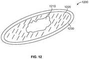
- FIG. 12provides a schematic view of an absorbent pad 1200 .
- the depicted absorbent pad 1200includes an absorbent core portion 1210 , a wicking portion 1220 , and a fiberglass outer ply 1230 .
- the absorbent core portion 1210is configured to absorb liquid, and may be made of, for example, sodium phosphate.
- the wicking portion 1220surrounds the absorbent core 1210 , and is configured to wick liquid toward the absorbent core 1210 .
- the fiberglass outer ply 1230surrounds the wicking portion and defines an exterior 1232 of the absorbent pad 1200 .
- the fiberglass outer play 1230is made of a non-flammable fiberglass to help reduce or eliminate any risk of fire and to help satisfy any applicable safety standards.
- the wicking portion 1220may be made of cellulose. Even though cellulose may be flammable, the cellulose may burn at a low enough temperature so that the fiberglass outer play 1230 may contain or reduce any flame resulting from the cellulose.
- the wicking portion 1220may be made of a non-flammable material.
- the wicking portion 1220is made of a fiberglass material, such as fiberglass batting insulation.
- FIG. 13illustrates a flowchart of a method 1300 for providing a dry floor assembly (e.g., assembly 100 ) that is configured to form or be positioned on a floor of an enclosed space (e.g., aircraft lavatory).
- the method 1300may employ structures or aspects of various embodiments (e.g., systems and/or methods) discussed herein.
- certain steps (or operations)may be omitted or added, certain steps may be combined, certain steps may be performed simultaneously, certain steps may be performed concurrently, certain steps may be split into multiple steps, certain steps may be performed in a different order, or certain steps or series of steps may be re-performed in an iterative fashion.
- a grid(e.g., grid 110 is provided).
- the gridis configured to provide a support surface for walking or standing, and also to provide openings for the drainage or removal of liquid from the walking surface.
- the gridhas an array of openings configured to allow passage of liquid, and includes members extending from a base to an upper surface configured to be walked upon, with the members having a cross-section that tapers from the base to the upper surface.
- the gridmay be cast or molded.
- the gridis cast using a non-flammable material.
- the gridis coated with a hydrophobic coating.
- a stripe.g., strip 116
- the stripin various embodiments is made of a metallic material and extends around a perimeter of the grid.
- a pan(e.g., pan 130 ) is disposed beneath the grid.
- the pandefines a cavity, and is configured to collect and/or direct the flow of liquid passing through the grid.
- a wicking layer(e.g., wicking layer 140 ) is provided.
- the wicking layeris configured to be interposed between the pan and the grid, and is configured to wick liquid that passes through the openings of the grid toward the pan.
- the wicking layerincludes plural sub-layers. For example, in the illustrated example, at 1314 plural sub-layers are provided, and at 1316 , each sub-layer is bonded at discrete points to at least one of an adjacent sub-layer or the grid.
- a support layer(e.g., support layer 150 ) is provided.
- the support layeris interposed between the wicking layer and the pan.
- the support layermay be bonded to the bottom of the wicking layer.
- the support layerincludes support openings that are smaller than the openings of the grid.
- the gridmay be joined to the pan (e.g., via the strip).
- the strip(which is made of a metallic material) is secured to a ledge of the pan via magnets.
- magnetsmay be distributed about the ledge of the pan and aligned with the strip.
- the ledgemay be made of a metallic material and the strip may have magnets attached thereto. Further alternatively, both the strip and the ledge may have magnets.
- a reservoir(e.g., reservoir 170 , reservoir 1170 ) is provided in fluid communication with the pan.
- the panhas a sloped floor configured to direct fluid to the reservoir. It may be noted that in some embodiments a reservoir may not be provided, and liquid allowed to accumulate in the pan. Further additionally or alternatively, an absorbent pad (e.g., absorbent pad 180 , absorbent pad 1200 ) may be provided in a cavity of the pan, or in a separate reservoir.
- At 1324 of the illustrated embodiment, at least one surround member(e.g., 160 a , 160 b , 160 c , 160 d of FIG. 9 ) is secured to the strip.
- the panmay be disposed in the floor of a lavatory, and the surround members placed on top of the strip, with the surround members secured to the strip (e.g., via the magnets of the ledge and/or additional magnets disposed on the surround member).
- a structure, limitation, or element that is “configured to” perform a task or operationis particularly structurally formed, constructed, or adapted in a manner corresponding to the task or operation.
- an object that is merely capable of being modified to perform the task or operationis not “configured to” perform the task or operation as used herein.
Landscapes
- Engineering & Computer Science (AREA)
- Architecture (AREA)
- Aviation & Aerospace Engineering (AREA)
- Civil Engineering (AREA)
- Structural Engineering (AREA)
- Mechanical Engineering (AREA)
- Physics & Mathematics (AREA)
- Electromagnetism (AREA)
- Floor Finish (AREA)
- Sink And Installation For Waste Water (AREA)
- Drying Of Solid Materials (AREA)
- Building Environments (AREA)
Abstract
Description
Claims (21)
Priority Applications (5)
| Application Number | Priority Date | Filing Date | Title |
|---|---|---|---|
| US16/175,337US10982439B2 (en) | 2018-07-13 | 2018-10-30 | Dry floor liquid disposal system |
| EP19170026.9AEP3594104B1 (en) | 2018-07-13 | 2019-04-18 | Dry floor liquid disposal system |
| JP2019080950AJP7364354B2 (en) | 2018-07-13 | 2019-04-22 | dry bed liquid disposal system |
| CN201910504763.2ACN110712739B (en) | 2018-07-13 | 2019-06-12 | Dry floor liquid treatment system |
| BR102019014345-2ABR102019014345B1 (en) | 2018-07-13 | 2019-07-11 | DRY FLOOR ASSEMBLY AND METHOD FOR PROVIDING DRY FLOOR ASSEMBLY |
Applications Claiming Priority (2)
| Application Number | Priority Date | Filing Date | Title |
|---|---|---|---|
| US201862697727P | 2018-07-13 | 2018-07-13 | |
| US16/175,337US10982439B2 (en) | 2018-07-13 | 2018-10-30 | Dry floor liquid disposal system |
Publications (2)
| Publication Number | Publication Date |
|---|---|
| US20200018065A1 US20200018065A1 (en) | 2020-01-16 |
| US10982439B2true US10982439B2 (en) | 2021-04-20 |
Family
ID=66239782
Family Applications (1)
| Application Number | Title | Priority Date | Filing Date |
|---|---|---|---|
| US16/175,337Active2038-11-21US10982439B2 (en) | 2018-07-13 | 2018-10-30 | Dry floor liquid disposal system |
Country Status (4)
| Country | Link |
|---|---|
| US (1) | US10982439B2 (en) |
| EP (1) | EP3594104B1 (en) |
| JP (1) | JP7364354B2 (en) |
| CN (1) | CN110712739B (en) |
Cited By (7)
| Publication number | Priority date | Publication date | Assignee | Title |
|---|---|---|---|---|
| US20210214085A1 (en)* | 2018-05-31 | 2021-07-15 | The Yokohama Rubber Co., Ltd. | Floor structure for aircraft lavatory unit |
| US11377194B2 (en) | 2018-10-01 | 2022-07-05 | Techno-Coatings, Inc. | Floating floor attachment system |
| US11479335B2 (en)* | 2019-01-28 | 2022-10-25 | Techno-Coatings, Inc. | Magnetic perimeter attachment for an aircraft flooring section |
| US11518492B2 (en) | 2019-01-28 | 2022-12-06 | Techno-Coatings, Inc. | Aircraft flooring architecture |
| EP4147971A1 (en) | 2021-09-08 | 2023-03-15 | The Boeing Company | Methods of forming a dry floor assembly |
| US12286083B2 (en) | 2022-10-27 | 2025-04-29 | The Boeing Company | Systems and methods for cleaning a floor of a lavatory within an internal cabin of a vehicle |
| US12297636B2 (en) | 2022-10-27 | 2025-05-13 | The Boeing Company | Systems and methods for cleaning a floor of a lavatory within an internal cabin of a vehicle |
Families Citing this family (3)
| Publication number | Priority date | Publication date | Assignee | Title |
|---|---|---|---|---|
| JP6777234B2 (en)* | 2018-05-31 | 2020-10-28 | 横浜ゴム株式会社 | Floor structure of aircraft dressing room unit |
| US11384535B2 (en) | 2020-06-08 | 2022-07-12 | The Boeing Company | Floor assemblies and methods |
| EP4001113B1 (en)* | 2020-11-18 | 2023-11-01 | The Boeing Company | Dry floor hardened grid |
Citations (42)
| Publication number | Priority date | Publication date | Assignee | Title |
|---|---|---|---|---|
| US456085A (en)* | 1891-07-14 | Door-mat | ||
| US543999A (en)* | 1895-08-06 | Combined mat and scraper | ||
| US3605166A (en)* | 1969-02-20 | 1971-09-20 | John W Chen | Floor mat construction |
| US3995328A (en) | 1974-12-13 | 1976-12-07 | The Boeing Company | Vacuum toilet system |
| US4420180A (en)* | 1982-02-11 | 1983-12-13 | Creations 2000, Inc. | Automobile floor mat with moisture collecting feature |
| US4533352A (en) | 1983-03-07 | 1985-08-06 | Pmt Inc. | Microsurgical flexible suction mat |
| US4819276A (en) | 1987-03-26 | 1989-04-11 | Stevens Robert B | Germicidal toilet seat |
| US5020638A (en)* | 1989-12-06 | 1991-06-04 | Smith Pok N | Vehicle liquid drip catching system |
| US5176667A (en) | 1992-04-27 | 1993-01-05 | Debring Donald L | Liquid collection apparatus |
| US5199457A (en)* | 1992-02-25 | 1993-04-06 | Miller David R | Leak detecting surface protector |
| US5349965A (en) | 1991-12-16 | 1994-09-27 | Kimberly-Clark Corporation | Surgical fluid evacuation system |
| US5827246A (en) | 1996-02-28 | 1998-10-27 | Tecnol Medical Products, Inc. | Vacuum pad for collecting potentially hazardous fluids |
| US6102073A (en)* | 1998-07-13 | 2000-08-15 | Williams; Kevin M. | Fluid-collecting receptacle |
| US6290685B1 (en) | 1998-06-18 | 2001-09-18 | 3M Innovative Properties Company | Microchanneled active fluid transport devices |
| US20020092110A1 (en)* | 1999-05-04 | 2002-07-18 | Blum Ronald D. | Floor mat support and drainage structure |
| US6470512B1 (en) | 1999-11-25 | 2002-10-29 | Airbus Deutschland Gmbh | Optimized shower arrangement for high volume use |
| US20030177572A1 (en) | 2002-03-22 | 2003-09-25 | Jeanne Guerin | Aircraft passenger cleansing system |
| US20030211291A1 (en) | 2002-05-13 | 2003-11-13 | 3M Innovative Properties Company | Fluid transport assemblies with flame retardant properties |
| US20040019993A1 (en)* | 1999-05-04 | 2004-02-05 | Blum Ronald D. | Floor mat with thermoformed insert area |
| WO2005012085A1 (en) | 2003-07-18 | 2005-02-10 | Telair International Gmbh | Floor for an aircraft cargo compartment an a method for the assembly thereof |
| US20060041238A1 (en)* | 2004-08-23 | 2006-02-23 | Bowen Michael L | Fluid collection system and method |
| US7051748B2 (en) | 2003-03-04 | 2006-05-30 | Vanbasten Willem F | Roll-up pool for a decontamination system |
| US7131965B1 (en) | 2001-12-20 | 2006-11-07 | Hemotrans, Inc. | Medical fluid collection and removal device |
| EP1808546A1 (en) | 2006-01-13 | 2007-07-18 | Wyco G.C.V. | Deck or floor panel and system comprising such panels |
| US7316834B2 (en)* | 2004-06-24 | 2008-01-08 | Roberto Hernandez | Drip mat |
| US7363936B1 (en)* | 2005-03-09 | 2008-04-29 | Logical Products, Inc. | Leakage catch basin and configurable storage unit |
| US20090241442A1 (en)* | 2002-10-29 | 2009-10-01 | Maclean James G | Self-cleaning flooring system |
| US8372506B2 (en)* | 2009-05-15 | 2013-02-12 | Leonid Vainshtein | Protective mat |
| US20130099055A1 (en) | 2011-10-24 | 2013-04-25 | Schneller, Inc. | Integrated lavatory pan for commercial aircraft |
| WO2014036217A2 (en) | 2012-08-29 | 2014-03-06 | Mag Aerospace Industries, Inc. | Aircraft galley and lavatory disinfection |
| US20140115764A1 (en) | 2012-10-25 | 2014-05-01 | Ying Chang Cheng | The sanitization mechanism of the toilet seat |
| US20140230185A1 (en)* | 2011-07-28 | 2014-08-21 | Maxime Pierrick François Burea | Collector of liquid |
| US8839812B2 (en)* | 2013-01-17 | 2014-09-23 | Deroyal Industries, Inc. | Surgical suction floor mat |
| US20150061380A1 (en)* | 2013-08-30 | 2015-03-05 | Airbus Operations Gmbh | Floor system for a vehicle and a vehicle having a cabin and a floor made by such a floor system |
| US20150298440A1 (en)* | 2013-02-21 | 2015-10-22 | Cocoon, Inc. | Thermal/acoustical liner |
| US20150322656A1 (en) | 2014-05-06 | 2015-11-12 | Mag Aerospace Industries, Llc | Modular lavatory wall with quiet flush plenum |
| US9623133B2 (en) | 2015-01-30 | 2017-04-18 | The Boeing Company | Lavatory disinfection system |
| EP3225549A1 (en) | 2016-03-31 | 2017-10-04 | The Boeing Company | Systems and methods for cleaning a lavatory floor |
| CN107232944A (en) | 2017-07-16 | 2017-10-10 | 佛山市米原信息系统科技有限公司 | It is a kind of from drainage type anti-slip carpet |
| US20180015862A1 (en)* | 2016-07-14 | 2018-01-18 | GM Global Technology Operations LLC | Debris and liquid retaining floor and cargo mats |
| WO2018077118A1 (en) | 2016-10-26 | 2018-05-03 | 董海舟 | Floor mat and production equipment and production method therefor |
| US10520241B1 (en)* | 2017-08-29 | 2019-12-31 | John Nelson | Drip tray for a snow blower |
Family Cites Families (15)
| Publication number | Priority date | Publication date | Assignee | Title |
|---|---|---|---|---|
| GB2066061A (en)* | 1979-12-21 | 1981-07-08 | Airomat Corp | Floor mat having anchoring elements and method of installing same |
| JPS63118872U (en)* | 1986-09-19 | 1988-08-01 | ||
| JPH09249062A (en)* | 1996-03-15 | 1997-09-22 | Daiko Seishi Kk | Water absorption and evaporation type floor mat |
| US6233776B1 (en) | 1999-05-04 | 2001-05-22 | Tech Mats, L.L.C | Advanced floor mat |
| US20060048469A1 (en) | 2002-10-29 | 2006-03-09 | Maclean James G | Self-cleaning flooring system |
| US20040109977A1 (en)* | 2002-12-09 | 2004-06-10 | Wildstein Arthur Samuel | Dual purpose floor mat |
| CA2485802A1 (en)* | 2004-10-22 | 2006-04-22 | James Sanderson | Cell mat |
| US20080280095A1 (en)* | 2006-06-13 | 2008-11-13 | Wright Rickie J | Surface protection mat |
| US20080166521A1 (en)* | 2007-01-05 | 2008-07-10 | R&L Marketing & Sales, Inc. | Self-contained mat assembly |
| US20090098031A1 (en)* | 2007-10-10 | 2009-04-16 | Tc Enterprise | Method and apparatus for sanitizing shoe soles |
| FR2952906B1 (en)* | 2009-11-23 | 2011-12-16 | European Aeronautic Defence & Space Co Eads France | AIRCRAFT FLOOR STRUCTURE AND METHOD FOR MANUFACTURING THE SAME |
| FR3007413B1 (en)* | 2013-06-20 | 2020-11-27 | Les Stratifies | PROCESS FOR EDGING COMPOSITE PANELS, TAPE FOR IMPLEMENTING THE PROCESS, PANEL OBTAINED BY THE PROCESS AND MACHINE FOR IMPLEMENTING THE PROCESS. |
| US10190688B2 (en)* | 2013-09-12 | 2019-01-29 | The Patent Well LLC | Elastomeric gel body gasket having a substantially incompressible skeleton, a method of making and using the same |
| US9737045B1 (en)* | 2014-03-17 | 2017-08-22 | Equipt4 LLC | Pet waste station and training device |
| CA2960113C (en)* | 2016-03-31 | 2021-07-20 | The Boeing Company | Systems and methods for automatically cleaning a lavatory floor |
- 2018
- 2018-10-30USUS16/175,337patent/US10982439B2/enactiveActive
- 2019
- 2019-04-18EPEP19170026.9Apatent/EP3594104B1/enactiveActive
- 2019-04-22JPJP2019080950Apatent/JP7364354B2/enactiveActive
- 2019-06-12CNCN201910504763.2Apatent/CN110712739B/enactiveActive
Patent Citations (45)
| Publication number | Priority date | Publication date | Assignee | Title |
|---|---|---|---|---|
| US456085A (en)* | 1891-07-14 | Door-mat | ||
| US543999A (en)* | 1895-08-06 | Combined mat and scraper | ||
| US3605166A (en)* | 1969-02-20 | 1971-09-20 | John W Chen | Floor mat construction |
| US3995328A (en) | 1974-12-13 | 1976-12-07 | The Boeing Company | Vacuum toilet system |
| US4063315A (en) | 1974-12-13 | 1977-12-20 | The Boeing Company | Vacuum toilet system |
| US4420180A (en)* | 1982-02-11 | 1983-12-13 | Creations 2000, Inc. | Automobile floor mat with moisture collecting feature |
| US4533352A (en) | 1983-03-07 | 1985-08-06 | Pmt Inc. | Microsurgical flexible suction mat |
| US4819276A (en) | 1987-03-26 | 1989-04-11 | Stevens Robert B | Germicidal toilet seat |
| US5020638A (en)* | 1989-12-06 | 1991-06-04 | Smith Pok N | Vehicle liquid drip catching system |
| US5349965A (en) | 1991-12-16 | 1994-09-27 | Kimberly-Clark Corporation | Surgical fluid evacuation system |
| US5199457A (en)* | 1992-02-25 | 1993-04-06 | Miller David R | Leak detecting surface protector |
| US5176667A (en) | 1992-04-27 | 1993-01-05 | Debring Donald L | Liquid collection apparatus |
| US5827246A (en) | 1996-02-28 | 1998-10-27 | Tecnol Medical Products, Inc. | Vacuum pad for collecting potentially hazardous fluids |
| US6290685B1 (en) | 1998-06-18 | 2001-09-18 | 3M Innovative Properties Company | Microchanneled active fluid transport devices |
| US6102073A (en)* | 1998-07-13 | 2000-08-15 | Williams; Kevin M. | Fluid-collecting receptacle |
| US20020092110A1 (en)* | 1999-05-04 | 2002-07-18 | Blum Ronald D. | Floor mat support and drainage structure |
| US20040019993A1 (en)* | 1999-05-04 | 2004-02-05 | Blum Ronald D. | Floor mat with thermoformed insert area |
| US6470512B1 (en) | 1999-11-25 | 2002-10-29 | Airbus Deutschland Gmbh | Optimized shower arrangement for high volume use |
| US7131965B1 (en) | 2001-12-20 | 2006-11-07 | Hemotrans, Inc. | Medical fluid collection and removal device |
| US20030177572A1 (en) | 2002-03-22 | 2003-09-25 | Jeanne Guerin | Aircraft passenger cleansing system |
| US20030211291A1 (en) | 2002-05-13 | 2003-11-13 | 3M Innovative Properties Company | Fluid transport assemblies with flame retardant properties |
| US20090241442A1 (en)* | 2002-10-29 | 2009-10-01 | Maclean James G | Self-cleaning flooring system |
| US7051748B2 (en) | 2003-03-04 | 2006-05-30 | Vanbasten Willem F | Roll-up pool for a decontamination system |
| WO2005012085A1 (en) | 2003-07-18 | 2005-02-10 | Telair International Gmbh | Floor for an aircraft cargo compartment an a method for the assembly thereof |
| US7316834B2 (en)* | 2004-06-24 | 2008-01-08 | Roberto Hernandez | Drip mat |
| US20060041238A1 (en)* | 2004-08-23 | 2006-02-23 | Bowen Michael L | Fluid collection system and method |
| US7363936B1 (en)* | 2005-03-09 | 2008-04-29 | Logical Products, Inc. | Leakage catch basin and configurable storage unit |
| EP1808546A1 (en) | 2006-01-13 | 2007-07-18 | Wyco G.C.V. | Deck or floor panel and system comprising such panels |
| US8372506B2 (en)* | 2009-05-15 | 2013-02-12 | Leonid Vainshtein | Protective mat |
| US20140230185A1 (en)* | 2011-07-28 | 2014-08-21 | Maxime Pierrick François Burea | Collector of liquid |
| US20130099055A1 (en) | 2011-10-24 | 2013-04-25 | Schneller, Inc. | Integrated lavatory pan for commercial aircraft |
| WO2014036217A2 (en) | 2012-08-29 | 2014-03-06 | Mag Aerospace Industries, Inc. | Aircraft galley and lavatory disinfection |
| US20140115764A1 (en) | 2012-10-25 | 2014-05-01 | Ying Chang Cheng | The sanitization mechanism of the toilet seat |
| US8839812B2 (en)* | 2013-01-17 | 2014-09-23 | Deroyal Industries, Inc. | Surgical suction floor mat |
| US20150298440A1 (en)* | 2013-02-21 | 2015-10-22 | Cocoon, Inc. | Thermal/acoustical liner |
| US20150061380A1 (en)* | 2013-08-30 | 2015-03-05 | Airbus Operations Gmbh | Floor system for a vehicle and a vehicle having a cabin and a floor made by such a floor system |
| US20150322656A1 (en) | 2014-05-06 | 2015-11-12 | Mag Aerospace Industries, Llc | Modular lavatory wall with quiet flush plenum |
| US9623133B2 (en) | 2015-01-30 | 2017-04-18 | The Boeing Company | Lavatory disinfection system |
| EP3225549A1 (en) | 2016-03-31 | 2017-10-04 | The Boeing Company | Systems and methods for cleaning a lavatory floor |
| US20170283062A1 (en) | 2016-03-31 | 2017-10-05 | The Boeing Company | Systems and methods for cleaning a lavatory floor |
| US10065740B2 (en) | 2016-03-31 | 2018-09-04 | The Boeing Company | Systems and methods for cleaning a lavatory floor |
| US20180015862A1 (en)* | 2016-07-14 | 2018-01-18 | GM Global Technology Operations LLC | Debris and liquid retaining floor and cargo mats |
| WO2018077118A1 (en) | 2016-10-26 | 2018-05-03 | 董海舟 | Floor mat and production equipment and production method therefor |
| CN107232944A (en) | 2017-07-16 | 2017-10-10 | 佛山市米原信息系统科技有限公司 | It is a kind of from drainage type anti-slip carpet |
| US10520241B1 (en)* | 2017-08-29 | 2019-12-31 | John Nelson | Drip tray for a snow blower |
Non-Patent Citations (1)
| Title |
|---|
| Extended European Sear Report dated Oct. 2, 2019 for corresponding EP Application No. 19170026.9-1010. |
Cited By (8)
| Publication number | Priority date | Publication date | Assignee | Title |
|---|---|---|---|---|
| US20210214085A1 (en)* | 2018-05-31 | 2021-07-15 | The Yokohama Rubber Co., Ltd. | Floor structure for aircraft lavatory unit |
| US11377194B2 (en) | 2018-10-01 | 2022-07-05 | Techno-Coatings, Inc. | Floating floor attachment system |
| US11479335B2 (en)* | 2019-01-28 | 2022-10-25 | Techno-Coatings, Inc. | Magnetic perimeter attachment for an aircraft flooring section |
| US11518492B2 (en) | 2019-01-28 | 2022-12-06 | Techno-Coatings, Inc. | Aircraft flooring architecture |
| EP4147971A1 (en) | 2021-09-08 | 2023-03-15 | The Boeing Company | Methods of forming a dry floor assembly |
| US11987035B2 (en) | 2021-09-08 | 2024-05-21 | The Boeing Company | Methods of forming a dry floor assembly |
| US12286083B2 (en) | 2022-10-27 | 2025-04-29 | The Boeing Company | Systems and methods for cleaning a floor of a lavatory within an internal cabin of a vehicle |
| US12297636B2 (en) | 2022-10-27 | 2025-05-13 | The Boeing Company | Systems and methods for cleaning a floor of a lavatory within an internal cabin of a vehicle |
Also Published As
| Publication number | Publication date |
|---|---|
| BR102019014345A2 (en) | 2020-02-04 |
| JP7364354B2 (en) | 2023-10-18 |
| EP3594104A1 (en) | 2020-01-15 |
| JP2020011710A (en) | 2020-01-23 |
| EP3594104B1 (en) | 2021-09-08 |
| CN110712739A (en) | 2020-01-21 |
| CN110712739B (en) | 2024-09-27 |
| US20200018065A1 (en) | 2020-01-16 |
Similar Documents
| Publication | Publication Date | Title |
|---|---|---|
| US10982439B2 (en) | Dry floor liquid disposal system | |
| EP3170741B1 (en) | Aircraft bay blankets that provide enhanced drainage features | |
| EP1735209B1 (en) | Adaptable payload enabling architecture | |
| US9545998B2 (en) | Bunk assembly and method of manufacturing thereof | |
| CA2870249A1 (en) | Dehumidification system for use in a vehicle and method of assembling thereof | |
| US20250304254A1 (en) | Emergency oxygen systems for internal cabins of aircraft | |
| US7954760B2 (en) | Cargo floor, system, and method | |
| US9815544B2 (en) | Modular replaceable slip joint intercostal | |
| US11885126B2 (en) | Floor assemblies and methods | |
| US11745846B2 (en) | Dry floor hardened grid | |
| US12275520B2 (en) | Liquid-diverting panel assemblies | |
| CN107054614B (en) | Device and method for discharging moisture for an aircraft | |
| EP4122815A1 (en) | Seat track assembly for use in an air vehicle | |
| BR102019014345B1 (en) | DRY FLOOR ASSEMBLY AND METHOD FOR PROVIDING DRY FLOOR ASSEMBLY | |
| US11260619B2 (en) | Composite panel systems and methods | |
| EP4400410A1 (en) | Interchangeable air distribution coupling interface for an internal cabin of a vehicle | |
| US20230116351A1 (en) | Fuel tank systems and methods for vehicles | |
| US11427328B2 (en) | Seat indexing systems and methods | |
| US20200130804A1 (en) | Alternative aircraft configurations for flight crew areas |
Legal Events
| Date | Code | Title | Description |
|---|---|---|---|
| AS | Assignment | Owner name:THE BOEING COMPANY, ILLINOIS Free format text:ASSIGNMENT OF ASSIGNORS INTEREST;ASSIGNOR:CHILDRESS, JAMES JOHNATHAN;REEL/FRAME:047360/0048 Effective date:20181029 | |
| FEPP | Fee payment procedure | Free format text:ENTITY STATUS SET TO UNDISCOUNTED (ORIGINAL EVENT CODE: BIG.); ENTITY STATUS OF PATENT OWNER: LARGE ENTITY | |
| STPP | Information on status: patent application and granting procedure in general | Free format text:RESPONSE TO NON-FINAL OFFICE ACTION ENTERED AND FORWARDED TO EXAMINER | |
| STPP | Information on status: patent application and granting procedure in general | Free format text:NON FINAL ACTION MAILED | |
| STPP | Information on status: patent application and granting procedure in general | Free format text:FINAL REJECTION MAILED | |
| STPP | Information on status: patent application and granting procedure in general | Free format text:ADVISORY ACTION MAILED | |
| STPP | Information on status: patent application and granting procedure in general | Free format text:DOCKETED NEW CASE - READY FOR EXAMINATION | |
| STPP | Information on status: patent application and granting procedure in general | Free format text:NOTICE OF ALLOWANCE MAILED -- APPLICATION RECEIVED IN OFFICE OF PUBLICATIONS | |
| STPP | Information on status: patent application and granting procedure in general | Free format text:PUBLICATIONS -- ISSUE FEE PAYMENT RECEIVED | |
| STPP | Information on status: patent application and granting procedure in general | Free format text:PUBLICATIONS -- ISSUE FEE PAYMENT VERIFIED | |
| STCF | Information on status: patent grant | Free format text:PATENTED CASE | |
| MAFP | Maintenance fee payment | Free format text:PAYMENT OF MAINTENANCE FEE, 4TH YEAR, LARGE ENTITY (ORIGINAL EVENT CODE: M1551); ENTITY STATUS OF PATENT OWNER: LARGE ENTITY Year of fee payment:4 |