US10980968B2 - Micro-cutting systems for forming cuts in products - Google Patents
Micro-cutting systems for forming cuts in productsDownload PDFInfo
- Publication number
- US10980968B2 US10980968B2US16/212,425US201816212425AUS10980968B2US 10980968 B2US10980968 B2US 10980968B2US 201816212425 AUS201816212425 AUS 201816212425AUS 10980968 B2US10980968 B2US 10980968B2
- Authority
- US
- United States
- Prior art keywords
- stock material
- cut
- cutting
- longitudinal axis
- cutting blade
- Prior art date
- Legal status (The legal status is an assumption and is not a legal conclusion. Google has not performed a legal analysis and makes no representation as to the accuracy of the status listed.)
- Active
Links
Images


Classifications
- A—HUMAN NECESSITIES
- A61—MEDICAL OR VETERINARY SCIENCE; HYGIENE
- A61M—DEVICES FOR INTRODUCING MEDIA INTO, OR ONTO, THE BODY; DEVICES FOR TRANSDUCING BODY MEDIA OR FOR TAKING MEDIA FROM THE BODY; DEVICES FOR PRODUCING OR ENDING SLEEP OR STUPOR
- A61M25/00—Catheters; Hollow probes
- A61M25/0009—Making of catheters or other medical or surgical tubes
- A61M25/0015—Making lateral openings in a catheter tube, e.g. holes, slits, ports, piercings of guidewire ports; Methods for processing the holes, e.g. smoothing the edges
- A—HUMAN NECESSITIES
- A61—MEDICAL OR VETERINARY SCIENCE; HYGIENE
- A61M—DEVICES FOR INTRODUCING MEDIA INTO, OR ONTO, THE BODY; DEVICES FOR TRANSDUCING BODY MEDIA OR FOR TAKING MEDIA FROM THE BODY; DEVICES FOR PRODUCING OR ENDING SLEEP OR STUPOR
- A61M25/00—Catheters; Hollow probes
- A61M25/01—Introducing, guiding, advancing, emplacing or holding catheters
- A61M25/09—Guide wires
- B—PERFORMING OPERATIONS; TRANSPORTING
- B26—HAND CUTTING TOOLS; CUTTING; SEVERING
- B26D—CUTTING; DETAILS COMMON TO MACHINES FOR PERFORATING, PUNCHING, CUTTING-OUT, STAMPING-OUT OR SEVERING
- B26D1/00—Cutting through work characterised by the nature or movement of the cutting member or particular materials not otherwise provided for; Apparatus or machines therefor; Cutting members therefor
- B26D1/01—Cutting through work characterised by the nature or movement of the cutting member or particular materials not otherwise provided for; Apparatus or machines therefor; Cutting members therefor involving a cutting member which does not travel with the work
- B26D1/12—Cutting through work characterised by the nature or movement of the cutting member or particular materials not otherwise provided for; Apparatus or machines therefor; Cutting members therefor involving a cutting member which does not travel with the work having a cutting member moving about an axis
- B26D1/14—Cutting through work characterised by the nature or movement of the cutting member or particular materials not otherwise provided for; Apparatus or machines therefor; Cutting members therefor involving a cutting member which does not travel with the work having a cutting member moving about an axis with a circular cutting member, e.g. disc cutter
- B26D1/24—Cutting through work characterised by the nature or movement of the cutting member or particular materials not otherwise provided for; Apparatus or machines therefor; Cutting members therefor involving a cutting member which does not travel with the work having a cutting member moving about an axis with a circular cutting member, e.g. disc cutter coacting with another disc cutter
- B—PERFORMING OPERATIONS; TRANSPORTING
- B26—HAND CUTTING TOOLS; CUTTING; SEVERING
- B26D—CUTTING; DETAILS COMMON TO MACHINES FOR PERFORATING, PUNCHING, CUTTING-OUT, STAMPING-OUT OR SEVERING
- B26D5/00—Arrangements for operating and controlling machines or devices for cutting, cutting-out, stamping-out, punching, perforating, or severing by means other than cutting
- B26D5/007—Control means comprising cameras, vision or image processing systems
- B—PERFORMING OPERATIONS; TRANSPORTING
- B26—HAND CUTTING TOOLS; CUTTING; SEVERING
- B26D—CUTTING; DETAILS COMMON TO MACHINES FOR PERFORATING, PUNCHING, CUTTING-OUT, STAMPING-OUT OR SEVERING
- B26D5/00—Arrangements for operating and controlling machines or devices for cutting, cutting-out, stamping-out, punching, perforating, or severing by means other than cutting
- B26D5/20—Arrangements for operating and controlling machines or devices for cutting, cutting-out, stamping-out, punching, perforating, or severing by means other than cutting with interrelated action between the cutting member and work feed
- B26D5/30—Arrangements for operating and controlling machines or devices for cutting, cutting-out, stamping-out, punching, perforating, or severing by means other than cutting with interrelated action between the cutting member and work feed having the cutting member controlled by scanning a record carrier
- B26D5/34—Arrangements for operating and controlling machines or devices for cutting, cutting-out, stamping-out, punching, perforating, or severing by means other than cutting with interrelated action between the cutting member and work feed having the cutting member controlled by scanning a record carrier scanning being effected by a photosensitive device
- B—PERFORMING OPERATIONS; TRANSPORTING
- B26—HAND CUTTING TOOLS; CUTTING; SEVERING
- B26D—CUTTING; DETAILS COMMON TO MACHINES FOR PERFORATING, PUNCHING, CUTTING-OUT, STAMPING-OUT OR SEVERING
- B26D7/00—Details of apparatus for cutting, cutting-out, stamping-out, punching, perforating, or severing by means other than cutting
- B26D7/06—Arrangements for feeding or delivering work of other than sheet, web, or filamentary form
- B26D7/0683—Arrangements for feeding or delivering work of other than sheet, web, or filamentary form specially adapted for elongated articles
- B—PERFORMING OPERATIONS; TRANSPORTING
- B26—HAND CUTTING TOOLS; CUTTING; SEVERING
- B26F—PERFORATING; PUNCHING; CUTTING-OUT; STAMPING-OUT; SEVERING BY MEANS OTHER THAN CUTTING
- B26F1/00—Perforating; Punching; Cutting-out; Stamping-out; Apparatus therefor
- B26F1/0015—Perforating; Punching; Cutting-out; Stamping-out; Apparatus therefor specially adapted for perforating tubes
- B26F1/0053—Perforating; Punching; Cutting-out; Stamping-out; Apparatus therefor specially adapted for perforating tubes by machining, e.g. cutting, grinding, projections on the tube wall
- B—PERFORMING OPERATIONS; TRANSPORTING
- B26—HAND CUTTING TOOLS; CUTTING; SEVERING
- B26F—PERFORATING; PUNCHING; CUTTING-OUT; STAMPING-OUT; SEVERING BY MEANS OTHER THAN CUTTING
- B26F1/00—Perforating; Punching; Cutting-out; Stamping-out; Apparatus therefor
- B26F1/0015—Perforating; Punching; Cutting-out; Stamping-out; Apparatus therefor specially adapted for perforating tubes
- B26F1/0061—Perforating; Punching; Cutting-out; Stamping-out; Apparatus therefor specially adapted for perforating tubes whereby the tube moves axially or radially
- B26F1/0076—Perforating; Punching; Cutting-out; Stamping-out; Apparatus therefor specially adapted for perforating tubes whereby the tube moves axially or radially and the tool rotates
- A—HUMAN NECESSITIES
- A61—MEDICAL OR VETERINARY SCIENCE; HYGIENE
- A61M—DEVICES FOR INTRODUCING MEDIA INTO, OR ONTO, THE BODY; DEVICES FOR TRANSDUCING BODY MEDIA OR FOR TAKING MEDIA FROM THE BODY; DEVICES FOR PRODUCING OR ENDING SLEEP OR STUPOR
- A61M25/00—Catheters; Hollow probes
- A61M25/01—Introducing, guiding, advancing, emplacing or holding catheters
- A61M25/09—Guide wires
- A61M2025/09108—Methods for making a guide wire
- Y—GENERAL TAGGING OF NEW TECHNOLOGICAL DEVELOPMENTS; GENERAL TAGGING OF CROSS-SECTIONAL TECHNOLOGIES SPANNING OVER SEVERAL SECTIONS OF THE IPC; TECHNICAL SUBJECTS COVERED BY FORMER USPC CROSS-REFERENCE ART COLLECTIONS [XRACs] AND DIGESTS
- Y10—TECHNICAL SUBJECTS COVERED BY FORMER USPC
- Y10T—TECHNICAL SUBJECTS COVERED BY FORMER US CLASSIFICATION
- Y10T83/00—Cutting
- Y10T83/04—Processes
- Y10T83/0448—With subsequent handling [i.e., of product]
- Y—GENERAL TAGGING OF NEW TECHNOLOGICAL DEVELOPMENTS; GENERAL TAGGING OF CROSS-SECTIONAL TECHNOLOGIES SPANNING OVER SEVERAL SECTIONS OF THE IPC; TECHNICAL SUBJECTS COVERED BY FORMER USPC CROSS-REFERENCE ART COLLECTIONS [XRACs] AND DIGESTS
- Y10—TECHNICAL SUBJECTS COVERED BY FORMER USPC
- Y10T—TECHNICAL SUBJECTS COVERED BY FORMER US CLASSIFICATION
- Y10T83/00—Cutting
- Y10T83/04—Processes
- Y10T83/0505—With reorientation of work between cuts
- Y10T83/051—Relative to same tool
- Y—GENERAL TAGGING OF NEW TECHNOLOGICAL DEVELOPMENTS; GENERAL TAGGING OF CROSS-SECTIONAL TECHNOLOGIES SPANNING OVER SEVERAL SECTIONS OF THE IPC; TECHNICAL SUBJECTS COVERED BY FORMER USPC CROSS-REFERENCE ART COLLECTIONS [XRACs] AND DIGESTS
- Y10—TECHNICAL SUBJECTS COVERED BY FORMER USPC
- Y10T—TECHNICAL SUBJECTS COVERED BY FORMER US CLASSIFICATION
- Y10T83/00—Cutting
- Y10T83/141—With means to monitor and control operation [e.g., self-regulating means]
- Y10T83/145—Including means to monitor product
- Y—GENERAL TAGGING OF NEW TECHNOLOGICAL DEVELOPMENTS; GENERAL TAGGING OF CROSS-SECTIONAL TECHNOLOGIES SPANNING OVER SEVERAL SECTIONS OF THE IPC; TECHNICAL SUBJECTS COVERED BY FORMER USPC CROSS-REFERENCE ART COLLECTIONS [XRACs] AND DIGESTS
- Y10—TECHNICAL SUBJECTS COVERED BY FORMER USPC
- Y10T—TECHNICAL SUBJECTS COVERED BY FORMER US CLASSIFICATION
- Y10T83/00—Cutting
- Y10T83/162—With control means responsive to replaceable or selectable information program
- Y10T83/173—Arithmetically determined program
- Y—GENERAL TAGGING OF NEW TECHNOLOGICAL DEVELOPMENTS; GENERAL TAGGING OF CROSS-SECTIONAL TECHNOLOGIES SPANNING OVER SEVERAL SECTIONS OF THE IPC; TECHNICAL SUBJECTS COVERED BY FORMER USPC CROSS-REFERENCE ART COLLECTIONS [XRACs] AND DIGESTS
- Y10—TECHNICAL SUBJECTS COVERED BY FORMER USPC
- Y10T—TECHNICAL SUBJECTS COVERED BY FORMER US CLASSIFICATION
- Y10T83/00—Cutting
- Y10T83/444—Tool engages work during dwell of intermittent workfeed
- Y10T83/4458—Work-sensing means to control work-moving or work-stopping means
- Y—GENERAL TAGGING OF NEW TECHNOLOGICAL DEVELOPMENTS; GENERAL TAGGING OF CROSS-SECTIONAL TECHNOLOGIES SPANNING OVER SEVERAL SECTIONS OF THE IPC; TECHNICAL SUBJECTS COVERED BY FORMER USPC CROSS-REFERENCE ART COLLECTIONS [XRACs] AND DIGESTS
- Y10—TECHNICAL SUBJECTS COVERED BY FORMER USPC
- Y10T—TECHNICAL SUBJECTS COVERED BY FORMER US CLASSIFICATION
- Y10T83/00—Cutting
- Y10T83/444—Tool engages work during dwell of intermittent workfeed
- Y10T83/4463—Work-sensing means to initiate tool feed
- Y—GENERAL TAGGING OF NEW TECHNOLOGICAL DEVELOPMENTS; GENERAL TAGGING OF CROSS-SECTIONAL TECHNOLOGIES SPANNING OVER SEVERAL SECTIONS OF THE IPC; TECHNICAL SUBJECTS COVERED BY FORMER USPC CROSS-REFERENCE ART COLLECTIONS [XRACs] AND DIGESTS
- Y10—TECHNICAL SUBJECTS COVERED BY FORMER USPC
- Y10T—TECHNICAL SUBJECTS COVERED BY FORMER US CLASSIFICATION
- Y10T83/00—Cutting
- Y10T83/828—With illuminating or viewing means for work
- Y—GENERAL TAGGING OF NEW TECHNOLOGICAL DEVELOPMENTS; GENERAL TAGGING OF CROSS-SECTIONAL TECHNOLOGIES SPANNING OVER SEVERAL SECTIONS OF THE IPC; TECHNICAL SUBJECTS COVERED BY FORMER USPC CROSS-REFERENCE ART COLLECTIONS [XRACs] AND DIGESTS
- Y10—TECHNICAL SUBJECTS COVERED BY FORMER USPC
- Y10T—TECHNICAL SUBJECTS COVERED BY FORMER US CLASSIFICATION
- Y10T83/00—Cutting
- Y10T83/869—Means to drive or to guide tool
- Y10T83/8878—Guide
Definitions
- the medical fieldutilizes highly flexible and torquable catheters and guidewires to perform delicate procedures deep inside the human body.
- Endovascular procedurestypically start at the groin where a catheter and guidewire are inserted into the femoral artery and navigated up to the heart, brain, or other anatomy as required. Once in place, the guidewire is removed so the catheter can be used for the delivery of drugs, stents, embolic devices to treat a variety of conditions, or other devices or agents.
- the cathetermay be a balloon catheter used for therapy directly, either by itself or with a balloon expandable stent pre-loaded on it.
- a radiopaque dyeis often injected into the catheter so that the vessels can be viewed intraprocedurally or in the case of a diagnostic procedure, the dye may be the primary or only agent delivered through the catheter.
- Intravascular procedureswork in and with delicate anatomy, namely the vessels themselves, which are often also compromised by disease. Damage to the vessels is particularly critical to avoid. If blood in the vessels is allowed to “leak,” direct damage can be caused to any tissue outside of the normal capillary approach contacted by the blood, and/or may result in a deadly problem of exsanguination or “bleed out”.
- the control of the catheter tipis especially important.
- An aneurysmis a very fragile ballooned vessel wall which can easily be punctured if the guidewire or catheter is not precisely controlled.
- Each cut made by the blade into the stockis based on the location of the electromagnetically sensed surface of the stock and the pre-programmed depth of the desired cut. Once a cut is made, the stock piece is rotated 180 degrees, the surface is sensed again, and another pre-programmed cut is made to a desired depth. As the cutting machine is incapable of determining the precise diameter (at the location of the cut) of the stock material being cut, each cut is made according to a preprogrammed depth regardless of that diameter. This is a problem because stock material is not always of a uniform shape and diameter—there are often imperfections along the length of stock that can affect both the roundness of the stock material and the diameter of the stock material at any particular location.
- a small beam of remaining materialis formed by the sequential, opposing cuts. This beam is referred to as a resultant beam. If the diameter of the stock is thicker than anticipated at the location of the cuts, then the resultant beam will be thicker and therefore less flexible than desired. If the diameter of the stock is thinner than anticipated at the location of the cuts, then the resultant beam will be thinner and therefore weaker than desired.
- the critical dimension that governs both strength (safety) and flexibility (performance)is the width of the resultant beam, which in current micro-cutting machines is not controlled directly and is instead the result of two imprecise measurements—the measure of the relative distance between the blade and the stock material for the first cut and the measure of the relative distance between the blade and the stock material for the second cut. Any imperfection in the surface of the stock material, or inconsistency in the diameter of such material, is directly translated to the resultant beam. This is problematic in terms of both safety and performance of the final product, whether it is a guidewire, catheter or other device.
- micro-cutting machinefor machining catheters, guidewires and other devices that utilizes two blades to cut both sides simultaneously, that is able to directly control the width of resultant beams, and that is capable of micro-cutting non-conductive material, such as plastic.
- Such a machinewould be faster, more predictable, and more versatile than current micro-cutting machines.
- Micro-cutting machines for forming cuts in catheters, guidewires, and similar productsare disclosed, including a dual blade micro-cutting machine that can directly control the dimensions of the resultant beams being cut into the products, that can capture images of each cut for feedback control and accuracy verification, and that generally can cut any material (such as plastic) independent of the conductivity of the material.
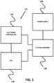
- FIG. 1illustrates a general overview of a micro-cutting machine in an embodiment
- FIG. 2Aillustrates a partially cut-away, plan view of a cutting assembly of the micro-cutting machine of FIG. 1 in an embodiment
- FIG. 2Billustrates a cross-sectional view of a piece of cylindrical stock material resting within a feed trough of the cutting assembly of FIG. 2A in an embodiment
- FIG. 3illustrates a desktop image generated by the imaging system and CPU of FIG. 1 depicting the stock material once it has been cut by the cutting assembly;
- FIG. 4illustrates the imaging system of the cutting assembly of FIG. 1 ;
- FIGS. 5A, 5B and 5Cillustrate different views of a product cut in accordance with an embodiment
- FIGS. 6A and 6Billustrate cross-sectional views of pieces of cylindrical stock material cut to form different products in accordance with an embodiment.
- the herein disclosed micro-cutting machineutilizes a pair of micro-cutting blades or other cutting members to precisely cut into opposing sides of a cylindrical stock material. By cutting both sides simultaneously while tightly controlling the distance between the blades or cutting members, the disclosed micro-cutting machine is capable of producing high performance catheters, guidewires and related products for interventional medical procedures, as well as other devices for a variety of additional uses. While an embodiment has been designed primarily for cutting stock material into flexible and torquable medical guidewires and catheters, the disclosed micro-cutting machine can certainly be used for other applications, and may be appropriate for making precise micro-cuts into a wide variety of cylindrical materials or perhaps even other extruded stock materials which may have non-circular cross-sectional shapes. The micro-cutting machine will mostly be described in regard to cutting guidewires and catheters, but those skilled in the art will recognize the broader applicability of the embodiment.
- FIG. 1illustrates a general layout of the micro-cutting machine in accordance with an embodiment.
- Micro-cutting machine 101includes cutting assembly 140 , which generally has at least a pair of blades or cutting members and two or more stock material controllers, including feed and rotate motors, for precisely advancing and controlling the angle of the cylindrical stock material as it is cut and then preparing for a next cut.
- Cutting assembly 140will be explained in much more detail below.
- Electronic controllers 110which may be one or more electronic controllers, which are referred to as an electronic controller unit) for providing precise control signals to the cutting assembly 140 to control the position and speed of the blades and the position and angle of the stock material.
- the electronic controllerscan also control the lights and a camera (an imaging system) for imaging the stock material before and after cuts and collecting data generated by the imaging system.
- a central processing unit 130(such as a personal computer that includes a display, input and output systems, a storage system, etc., or some other type of CPU) receives user input, controls the electronic controllers 110 and the cutting assembly 140 , and processes data generated by the imaging system to adjust the relative gap distance between the two blades. Alternatively, the CPU 130 could communicate directly with the imaging system and by-pass the electronic controllers 110 .
- a power supply 120supplies power to at least the cutting assembly 140 , and possibly other components of the micro-cutting machine 101 .
- FIG. 2Aillustrates a plan view of an embodiment of cutting assembly 140 , which is mounted on a stationary frame assembly 200 .
- the stock material 202is fed into the cutting assembly 140 by the feed motor assembly 204 , which can hold the stock material in a fixed position relative to the X-axis (shown in FIG. 2A as axis 240 ), the direction parallel to the spindle 206 , and which can move the stock material along the X-axis by very small, controlled increments, so as to appropriately feed the stock material 202 into the cutting assembly 140 , as further discussed below.
- the feed motor assembly 204may comprise two feed motors (not separately shown), one for gripping the stock material 202 while it is being cut, as further described below, and one for moving the stock material 202 along the X-axis when the stock material 202 has been released by the first feed motor.
- the stock material 202 shown in FIG. 2Ais not illustrated as its actual size.
- the outer diameter of the stock material 202can be 0.030 inches or less, or about 3 French on the French catheter scale, where a French is equal to three times the outer diameter of the stock material 202 measured in millimeters. Converting to inches, 3 French is equal to 0.039 inches, 4 French is equal to 0.053 inches, 5 French is equal to 0.066 inches, 6 French is equal to 0.079 inches, etc. Accordingly, based on the relative size of the cutting assembly shown in FIG. 2A , even a length of 6 French stock material 202 would be so small as to be almost impossible to see clearly, so the stock material 202 illustrated in FIG. 2A is much larger than its actual size for purposes of this illustration only.
- the feed motor assembly 204is mounted on a spindle 206 that is supported within the bearings of a bracket 208 mounted to the stationary frame assembly 200 .
- a pulley 210 mounted to the spindle 206is driven by a belt (not shown) that is, in turn, connected to another pulley (not shown) below the pulley 210 , which is connected to a rotational motor (not shown) mounted within the stationary frame assembly 200 .
- the rotational motoris a stepper motor, or the like, that is capable of extremely precise computer controlled movement.
- the rotational motorcan be programmed to cause the pulley 210 to rotate a specified number of degrees, so as to rotate the spindle 206 and feed motor 204 by the same specified number of degrees.
- the entire feed motor assembly 204rotates, along with any gripped stock material 202 when the pulley 210 and spindle 206 are rotated by the rotational motor.
- Alternative embodimentscould include different arrangements of the feed motor assembly 204 and the rotational motor, such as a feed motor assembly that only moves the stock material 202 along the X-axis and a rotational motor that grips and turns the stock material 202 when it is not being fed along the X-axis.
- the stock material 202is shown exiting the feed motor assembly 204 supported by an elongated feed trough 212 , which extends from the feed motor assembly 204 to one side of the cutting area (where the stock material 202 is cut by the blades 214 , as further described below), and then extends from the other side of the cutting area to an output area 216 .
- the length of the feed trough 212 between the feed motor assembly 204 and the cutting areawould be relatively short. This enables the feed motor assembly 204 to be much closer to the cutting area, such that the stock material 202 would be cut almost immediately upon exiting the feed motor assembly 204 .
- Keeping the length of the stock material 202 short between the feed motor assembly 204 and the cutting areahelps to better control the stock material 202 while it is being cut, i.e., preventing the stock material 202 from moving along the Y-axis (shown in FIGS. 2A and 2B as axis 242 ), the direction perpendicular to the spindle 206 , or rotating while the stock material 202 is being cut.
- the stock material 202is likely to be substantially rounded in shape, although other shapes could also be used.
- the stock material 202has both width and height, giving it a Y-axis and Z-axis (shown in FIG. 2B as axis 244 ) position, where the Z-axis is vertical to a plane including the X-axis and Y-axis.
- the feed trough 212is intended to passively guide the stock material 202 as it is moved along the x-axis, which it could do in many different ways, such as through the utilization of precisely located guide posts or elongated members or a guide path that maintains the stock material 202 in a desired position relative to the Y-axis and Z-axis.
- the guide path of the feed trough 212 for rounded stock material 202is preferably V-shaped, as illustrated by the cross section shown in FIG. 2B , wherein the stock material 202 lies in the bottom of the point formed by the V-shaped guide path within the feed trough 212 .
- the cutting areais defined by a small gap between the two sections (prior to and after the cutting area) of the feed trough 212 where a pair of opposing blades 214 cut the stock material 202 .
- the two blades 214can be either semiconductor dicing blades or standard “tooth” type blades formed of a carbide material, such as tungsten carbide, to improve wear resistance.
- the submicron grain size of tungsten carbide and similar compositesworks well because they are less brittle, extremely hard, and can maintain their sharpness even at very small blade thicknesses.
- additional different types of cutting instruments and systemscould be utilized in place of the blades 214 , such as water jet cutting systems, flame or oxyfuel cutting systems, plasma (arc) cutting system, electric discharge machining (EDM), etc., although not all of these systems are appropriate for use when cutting non-metal stock material or even certain types of metal stock materials, such as softer metals and less conductive metals.
- a “dual blade” systemit is to be understood that any type of alternative cutting member or cutting system could also be used, depending on the application involved.
- An embodiment for cutting plasticutilizes a tooth type blade with approximately 56 teeth.
- a blade thickness of approximately 0.006 and 0.008 inchesworks well.
- a diamond semiconductor dicing blade with a thickness of approximately 0.002 inchesworks well. Given such thickness, the size of the open cutting area between the two sections of feed trough 212 represented in FIG. 2A is not to scale and is exaggerated in size in order to more clearly illustrate the opening of the cutting area.
- the embodimentdoes not require the stock material 202 to be of a metallic composition so its location can be electromagnetically sensed by the blades 214 before a cut can be made.
- the embodimentcan be used to cut any type of material, whether metallic or non-metallic, such as PEEK, a semi-crystalline, high temperature thermoplastic that is ideal for use in catheters due its high modulus of elasticity resulting in torqueability and the ability to hold a shape.
- PEEKa semi-crystalline, high temperature thermoplastic that is ideal for use in catheters due its high modulus of elasticity resulting in torqueability and the ability to hold a shape.
- the blades 214are located within a blade enclosure 218 (shown without its top in FIG. 2A so the interior can be viewed) through which air can be pumped to cool the blades 214 and the stock material 202 , and through which debris cut from the stock material 202 can be removed.
- the hoses 220 of the air handling systemcan be used for pumping air and/or vacuuming air from the blade enclosure 218 .
- the blades 214can also be water cooled, as is known in the art.
- each of the blades 214is attached to a spindle 222 , that is oriented parallel to the X-axis.
- Each of the spindles 222is driven by a belt 224 that is rotated by a pulley attached to the spindle motor 226 .
- the spindle motor 226is program controlled through the electronic controllers 110 and the CPU 130 .
- the blades 214are driven indirectly in this manner so as to achieve greater rotational speeds than would be possible or practical with a direct drive arrangement.
- the spindle motor 226is capable of running at approximately 4,000 revolutions per minute (rpm) over an extended period of time without stressing the spindle motor 226 or any of the bearings supporting the pulley.
- the aspect ratio between the pulley and the spindle 222is approximately 6:1, so the slower rotating spindle motor 226 is capable of rotating the spindle at approximately 24,000 rpm, the desired speed for cutting PEEK and other materials.
- a direct drive motor capable of operating at 24,000 rpmwould be significantly more expensive, require different bearing assemblies, and likely have a significantly higher failure rate.
- each cutting assemblyis attached to a blade stepper motor 228 that controls the Y-axis location of each blade 214 .
- the stepper motors 228are mounted on a movable frame assembly 230 , as further described below.
- Each of the stepper motors 228are program controlled through the electronic controllers 110 and the CPU 130 , or can be manually adjusted through the control knobs 232 .
- each of the stepper motors 228are adjusted to a predetermined location such that the blades 214 are close but not touching, and a cut is made in the uncut stock material 202 with both blades at the same time.
- the manner in which both blades cut the stock material 202 simultaneouslyis further described below.
- the resultant beamis measured to determine if it is of the desired dimension.
- the stepper motors 228are then adjusted along the Y-axis to move the cutting assemblies inward toward each other or outward away from each other, and another cut is made to the uncut stock material 202 . This process is continued until the desired resultant beam dimension is achieved, at which point a series of cuts in the uncut stock material 202 is carried out.
- each blade 214By mounting the cutting assemblies on the stepper motors 228 , it is possible to precisely control the Y-axis location of each blade 214 and to accommodate a larger variety of different stock materials 202 , such as raw wire, tubing, and other shapes and sizes of cylindrical stock materials 202 .
- the stepper motors 228can move the cutting assemblies apart to accommodate the larger than normal stock material.
- the stepper motors 228can be precisely controlled by electronic controllers 110 and processor 130 to position the blades 214 to make cuts resulting in the desired resultant beam width, whether that be 0.002 inches, 0.0025 inches, 0.003 inches, 0.004 inches, etc.
- the desired resultant beam widthcan be precisely controlled by electronic controllers 110 and processor 130 to position the blades 214 to make cuts resulting in the desired resultant beam width, whether that be 0.002 inches, 0.0025 inches, 0.003 inches, 0.004 inches, etc.
- almost any desired dimensioncan be machined at any specified location.
- Both of the cutting assemblies and the stepper motors 228are in turn mounted on the movable frame assembly 230 , which is moved up and down along the Z-axis by a Z-axis motor (not shown) located within the movable frame assembly 230 and mounted on a non-visible portion of the stationary frame assembly 200 .
- a Z-axis motor(not shown) located within the movable frame assembly 230 and mounted on a non-visible portion of the stationary frame assembly 200 .
- the blade enclosure 218can be designed to be mounted to the movable frame assembly 230 , such that the blade enclosure 218 moves along with the blades 214 , or blade enclosure 218 could include two slots within which the spindles 222 could move up and down apart from the blade enclosure 218 . So as to better seal the interior of the blade enclosure, it is preferable to have the blade enclosure 218 move with the blades 214 .
- the camera 234could be any of a number of commercially available high-speed digital video cameras as long as it is capable of capturing high quality pixilated video image data.
- the camerais a model AM-413T digital microscope camera, manufactured by SunriseDino of New Hyde Park, N.Y.
- the more interesting aspects of the imaging systemare the manner in which the stock material 202 is backlit and illuminated in order to increase contrast around the edges of the cut stock material 202 and how the digital image processing is capable of precisely measuring both cuts and the resultant beams.
- FIG. 3is an illustration of a desktop image 300 generated on the display of the CPU 130 .
- the desktop image 300includes an imaging window 302 and a control window 304 .
- the imaging window 302displays digital video images of the stock material 202 as it is being cut and as it is being measured by the imaging system.
- the area 306shows the stock material 202 just after it has been cut by the blades 214 and the blades 214 have moved beyond the focused view of the camera 234 .
- the stock material 202 being cut in the example illustrated in FIG. 3is a tube used to make a catheter that is being rotated ninety degrees) (90.degree.) after each cut.
- holes 308are formed in the walls of the stock material 202 that become visible as the stock material 202 is turned in order to make the next cut.
- the stock material 202advances along the X-axis of the cutting assembly, the stock material 202 passes in front of a backlight, illustrated by the circle 310 .
- the backlight 410is held in place below the cutting area by an anvil that is affixed to the stationary frame assembly 200 and is positioned to illuminate the stock material 202 just after it has been cut, although the stock material 202 can also be seen in imaging window 302 just as it is being cut.
- Camera 234is communicatively coupled to processor 130 (not shown in FIG. 4 ) in order to provide feedback while the stock material 202 is being cut, and in order to store one or more images of one or more resultant beams 314 .
- a set of one or more green and blue LEDs 430can be positioned above the stock material 202 and around the camera 234 to provide additional lighting 440 for a user to see the top side of the stock material for manual inspection purposes.
- the combination of a red backlight 410 and the green and blue LEDs 430was selected because the camera 234 provides three color image channels of image data (red, green and blue) and the separately colored lighting enables the image data to be easily separated.
- the CPU 130 (and the software it operates) receiving the image datauses the red image channel for edge detection because it provides a high-contrast back lit image of the cut with no front side reflections that would confuse the measurement software being utilized by the CPU 130 to measure each cut.
- the green and blue image data created by the green and blue LEDs 430 and the camera 234are transmitted through the green image channel and the blue image channel, respectively.
- the camera 234could theoretically capture an image of every single cut made to the stock material 202 , doing so would generate an excessive amount of data that could not be competently reviewed at a reasonable cost by human operators. Instead, so as to provide adequate quality control, images are captured and recorded on a periodic or random (randomized test sampling protocol) basis, as further described below. While an image of the stock material 202 is being captured, as illustrated in FIG. 3 , two visual overlays 312 are applied by the imaging system to the image data within the back lit area 310 to determine the length of each cut and the resultant beam 314 , which is referred to as the “web” in FIG. 3 . The overlays 312 measure across the stock material 202 at two or more different points, including at least the width or thickness of the stock material 202 and the width of the web or resultant beam 308 .
- the measurements taken by the overlays 312are then analyzed by the CPU 130 and utilized to determine the length of the left cut, the right cut and the resultant beam or web 314 .
- the measurements taken by the overlays 312are then analyzed by the CPU 130 and utilized to determine the length of the left cut, the right cut and the resultant beam or web 314 .
- the CPU 130uses real-time image processing software operated by the CPU 130 to determine accurate measurements from the image data alone, without having to make use of mechanical measuring means. For example, if it is known that a piece of stock material 202 to be cut should have a width of 0.039 inches and the image data has a pixilation of 500 pixels per 0.05 inches, then approximately 390 pixels correspond to the width of the stock material 202 .
- the resultant beam 314will still be within an acceptable range of its normal size because the position of the blades 214 relative to the stock material 202 is largely based on the centered position of the stock material 202 , versus the known technique of basing each cut on the relative difference of the separate blades to the side of the stock material each blade is responsible for cutting.
- thicker stock material 202is cut, more stock material is cut away and when thinner stock material 202 is cut, less stock material is cut away, but in each case leaving a resultant beam of the desired size, versus generating thicker or thinner desired resultant beams, as is common in the art.
- the control window 304displays each measurement in a log section 318 of the control window that can be scrolled.
- the CPU 130has been programmed to instruct the imaging system to capture an image and measure the left cut, the right cut and the web on a periodic basis.
- the first cut shownwas grind 995 that resulted in a left cut (CUTL) of 0.0018 inches, a right cut (CUTR) of 0.0013 inches, and resulted in a web of 0.0359 inches, as noted above.
- the measurements and image file for grind 995is then stored in a data file labeled A.sub.—133.JPG.
- the grinds being recordeddo not necessarily correspond to the same number of cuts that have been made, as more or less cuts may be made than are imaged, measured and recorded. Hence the steps illustrated as part of the log section 318 may correspond to a separate programmed process that keeps track of the number of cuts that have been made.
- the control window 304also includes selectable buttons 320 that allow an operator to stop or pause a job or start and stop the cutting process.
- the operatoralso has the option of assigning a title to each cutting job and to store the data associated with that cutting job in a particular folder on the CPU 130 .
- the CPU 130provides programmed control of the electronic controllers 110 , the rotational motor and the feed motor assembly 204 to control the movement of the feed stock 202 into the cutting assembly 140 along the X-axis.
- the CPU 130would instruct the rotational motor either to leave the stock material 202 at its current orientation or to rotate it by some degree specified by the CPU 130 .
- the feed motor assembly 204would advance the stock material 202 by some specified amount along the X-axis to position it for the next cut and grip the stock material 202 .
- the rotational motorwould then rotate the feed motor assembly 204 and the stock material 202 would be cut again. This process would then be repeated until all of the stock material 202 has been cut as desired.
- the cutting assembly 140can generate a cut stock material 202 with resultant beams 314 that are not all aligned in the same orientation along the length of the micro-machined product.
- the stock material 202could be turned ninety degrees from its angle at the time of the last cut, or many variations thereof, such as turned five or more degrees short of ninety degrees (i.e., 85 degrees) from the angle of the last cut, or even cut at random angles relative to the angle of the last cut.
- An additional feature of the embodimentis the ability to measure the stock material 202 prior to being cut and using the resultant measurement to guide the depth of cuts. If stock material 202 was assumed to be 0.039 inches in diameter and it was desired to create a resultant beam 314 having a thickness of about 0.008 inches, then each cut would need to be 0.0155 inches deep. If the imaging system determined that the stock material 202 was only 0.032 inches in diameter instead of 0.039 inches, then the cutting machine would know that it needed to reduce the depth of each cut to 0.012 inches so as to leave the desired resultant beam 314 of 0.008 inches.
- the blades 214may be desirable to operate in an “offset cut” mode, wherein the blades 214 are not aligned in the same plane and deeper cuts are made.
- the cutsappear as independent cuts from each side (although cut simultaneously). The depth would then be important as each resultant beam, and the flexibility and stability of this type of structure, would be determined by the distance from the end of the cut to the opposing side of the tube.
- the embodimentpresently relies upon a quality control technique that measures only some of the cuts after they have been made instead of every cut.
- Thisenables the system to monitor the quality of the stock material 202 and other aspects of the system, but does not necessitate changing how the system is operating from cut to cut.
- stock material 202was out of specification, it is not likely that its diameter would only vary at a single isolated point. Rather, if stock material 202 was out of specification at one point, it would likely be out of specification along of a length of the material or be out of specification at multiple individual points, one or more of which would be detected through the quality control technique. Large variations in the diameter of the stock material 202 may make the stock material undesirable for certain applications, so if this was determined, the cutting assembly 140 could be stopped and the product discarded once detected.
- a main purpose of the micro-cutting machineis to make pairs of cuts (but not necessarily opposing) on cylindrical stock material to form flexible and torquable products, such as guidewires, catheters and other similar types of devices, all referred to herein as “products”. While it is known in the art to create a flexible and torquable guidewire and catheter by making a single cut with a blade into a side of a cylindrical piece of stock material (metal wire and/or tubing), and then rotating the material and making an opposing cut on the opposite side of the stock material with the same blade.
- the diameter of the stock materialis reduced in numerous places, which increases the flexibility of the resulting product, but since the product retains the same overall outside diameter, the resulting product is able to retain much of its torquability.
- the stock material cut in this fashionis usually cylindrical, since the cuts are made from opposing sides or nearly opposing sides toward the middle, it is helpful to think of the stock material as having a first side and a second side, even though in reality the stock material is substantially round and has only a single side.
- FIG. 5Aillustrates the resulting beams that are generated by circular blades that cut from a first side and then a second side, a resulting beam that can also be generated through utilization of the embodiment.
- FIGS. 5B and 5Cillustrate resulting beams that can only be generated through utilization of the embodiment.
- a cross-sectional view of solid stock material 202is shown in FIGS. 5A, 5B and 5C . Based on existing technology, when the solid stock material 202 has been cut on the first and second sides (either all at once, as is presently disclosed, or on the first side and then on the second side, as is known in the art), a resultant beam 510 would remain.
- This type of resultant beam 510is known in the art as a radius cut beam because it tapers from the circumference to the center point.
- Existing technologycuts the solid stock material 202 by advancing toward the solid stock material 202 along the Y-axis described above. As a result, the circular blade cuts the stock material 202 further in the central area than it can on the outer areas, always resulting in the radius cut beam 510 .
- a radius cut beam 510is appropriate for some uses, it is not ideal from a torquability and safety perspective.
- the reduced thickness of the central area of the radius cut beam 510enables stress to build up in that area as the product is twisted, which can result in breakage of the product. Given that products are often used in intravascular procedures, any breakage is highly undesirable. Likewise, if there is any irregularity in the diameter of the product, which irregularity cannot be sensed by the cutting machine, the cutting machine will make a cut in the product based on its programming alone.
- each cutwould need to be 0.0155 inches deep. If the guidewire, however was only 0.032 inches in diameter and the cutting machine used electromagnetic sensing, instead of real-time imaging, then each side would still be cut by 0.0155 inches, leaving a resultant beam of 0.001 inches, which would also likely result in breakage when inserted into a simple curve.
- the presently disclosed cutting machineoperates by moving the dual blades 214 along both the Y-axis and the Z-axis and is capable of creating a variety of differently shaped resultant beams, including the radius cut beam of FIG. 5A , as well as the straight cut beam of FIG. 5B and the convex cut beam of FIG. 5C .
- the cutting assembliesare moved above the stock material 202 along the Z-axis and adjusted along the Y-axis to create a distance between the blades, or other cutting member being used, sufficient to create a resultant beam of a desired thickness, then the cutting assemblies are brought down along the Z-axis and across the stock material 202 .
- a cutcan be made, the resultant beam measured, and the cutting assemblies can be further adjusted along the Y-axis until a resultant beam of the desired width has been created.
- a reference stock of a known widthcan be placed between the blades/cutting members until both blades/members touch the reference stock.
- a radius cut beam 510 or a convex cut beam 530could be created by the herein disclosed micro-cutting machine by moving the cutting assemblies inward and outward along the Y-axis as each cut is being made. It would also be possible to make a variety of other types of cuts and resultant beams by varying combinations of elements at the same time, such as rotating the stock material 202 with the rotation motor as a cut is being made, or rotating the stock material 202 and moving the cutting assemblies along the Y-axis at the same time. For example, a spiral cut could be made by leaving the cutting assemblies at a set Y-axis position while the stock material 202 is rotated by the rotational motor.
- the automated feedback and control process carried out by the imaging system 400 and the processor 130can account for slight variances in cutting blade variations or in variations or imperfections of the stock material itself.
- the resultant beamis the critical dimension and could be affected by even a single blade variation (such as a single blade tooth being too long) or by a variation of the diameter of the stock material throughout its length. All these factors are of course integrated into and manifest themselves in the resultant beam dimension.
- the precise measurement and adjustment capabilities of the embodimentresult in unprecedented precision.
- the processor 130can make adjustments to bring all parameters into alignment to create precise resultant beam widths.
- This processcan be executed at the beginning of manufacture, as a set-up process, as one or more cuts are being made, as a periodic check, or as each and every cut is being made.
- the software run on processor 130can be used to validate the repeatability of the micro-cutting machine, possibly reducing the number of measurements necessary while cutting a piece, or rendering continuous measurements unnecessary.
- the micro-cutting machine of the embodimentis capable of micro-cutting a wide variety of stock materials.
- Traditional single-blade micro-cutting machinesmake use of electromagnetic sensing of the precise location of the stock material relative to the single blade, thereby requiring the use of stock material that is conductive. This condition rules out the use of plastic tubing stock material or any other non-conductive or minimally conductive material (referred to herein as “non-conductive” even if the material has some relatively low conductivity that is insufficient to be cut by prior machines).
- the high definition images and measuring capabilities of the imaging system and the precise positioning of the cutting assemblies of the embodimentare much more accurate than relying upon sensing a surface of the stock material because the stock material itself can have an imperfect or inconsistent diameter. Therefore, the herein disclosed micro-cutting machine is much more accurate and can therefore cut finer dimension resultant beams with greater reliability.
- the physical arrangement of the components of the cutting assembly 140 and the stock material 202make it possible to cut harder materials with less natural flexibility, like stainless steel, because the resultant beams can be cut very narrow while retaining precision.
- the dual blade micro-cutting machine of the embodimentis therefore fully capable of cutting stainless steel catheters and guidewires (greatly desired by surgeons for its ability to hold a shape—allowing the surgeon to personally shape the tip of a stainless steel guidewire to match the patient's endovascular system just prior to use), plastic catheters and guidewires (desirable for their great flexibility at relatively wider diameters), and other non-magnetic stock materials for all types of products.
- Flexible yet torquable productsare formed by repeating micro-cuts throughout either the entire length of a piece of stock material, or along one or more portions of the piece of stock material.
- the pairs of cuts(a pair of cuts refers to one pass by the dual blades even though the cuts may not be opposite) are ideally made in a rotating pattern along the longitudinal axis of the cylindrical stock material.
- a rotating patternis preferred because making all cuts at the same angle creates a product that is biased toward flexing in one direction—perpendicular to the resultant beam.
- Feed motor 210grips the stock material 202 as the rotational motor rotates the stock material 202 along the X-axis (the longitudinal axis of the stock material 202 ), according to directions received by electronic controllers 110 and determined by processor 130 .
- the rotation between pairs of cutsis referred to as a variance, and is measured in the degree of rotation about the longitudinal axis of the stock material.
- FIGS. 6A and 6Billustrate two examples of a rotating pattern of pairs of cuts and resultant beams.
- FIG. 6Aillustrates a ninety degree variance guidewire 601 that was micro-cut using the dual blade micro-cutting machine of the embodiment.
- Cross-sectional view 620illustrates the two different angles at which pairs of cuts are made when the stock material is rotated ninety degrees between cuts.
- Plane view 630illustrates how such a guidewire 601 appears along its length.
- FIG. 6Billustrates a forty-five degree variance guidewire 602 that was micro-cut using the dual blade micro-cutting machine of the embodiment.
- Cross-sectional view 640illustrates the four angles at which pairs of cuts are made when the stock material is rotated forty-five degrees between cuts.
- Plane view 650illustrates how such a guidewire 602 appears along its length.
- an exemplary embodimentmay utilize an uneven variance between cuts, such as ninety-five degrees, or forty degrees, so that the pairs of cuts, and therefore the resultant beams, truly spiral around the longitudinal axis—completely eliminating flexing bias in any one direction.
- the variance used in cutting a productcan be even more complex. For example, advantageous results can be achieved by using a ninety degree variance between a first cut and a second cut, and then rotating the stock material slightly, such as by five degrees, before making a third cut and a fourth cut, the third cut and the fourth cut again using a ninety degree variance.
- An additional feature of the dual blade micro-cutting machine of the embodimentis an ability to cut a serial number using the blades 234 or cutting member as controlled by the cutting assembly 140 , electronic controllers 110 and CPU 130 into the stock material 202 , so that the final product can be individually identified.
- the serial number or other form of identificationcould be formed by creating a series of cuts in the stock material 202 (possibly circumferentially so they can be read regardless of the rotation of the stock material 202 ) of varying width and/or varying spacing that could be read in a manner similar to a bar code.
- micro-cutting machinehas been described as utilizing a pair of cutting blades cutting simultaneously, it also may be possible to configure a micro-cutting machine utilizing two or more pairs of cutting blades or members operating concurrently. In this way, it may be possible to operate a plurality of resultant beams all at one time.
- the pairs of cutting memberswould all be communicatively connected to electronic controllers 110 and processor 130 , so that they can each be adjusted in unison to machine a product meeting the desired resultant beam parameters.
Landscapes
- Life Sciences & Earth Sciences (AREA)
- Engineering & Computer Science (AREA)
- Forests & Forestry (AREA)
- Mechanical Engineering (AREA)
- Health & Medical Sciences (AREA)
- General Health & Medical Sciences (AREA)
- Veterinary Medicine (AREA)
- Anesthesiology (AREA)
- Biomedical Technology (AREA)
- Heart & Thoracic Surgery (AREA)
- Hematology (AREA)
- Animal Behavior & Ethology (AREA)
- Biophysics (AREA)
- Public Health (AREA)
- Pulmonology (AREA)
- Computer Vision & Pattern Recognition (AREA)
- Milling Processes (AREA)
- Media Introduction/Drainage Providing Device (AREA)
- Machine Tool Sensing Apparatuses (AREA)
- Treatment Of Fiber Materials (AREA)
- Laser Beam Processing (AREA)
- Meat, Egg Or Seafood Products (AREA)
- Preliminary Treatment Of Fibers (AREA)
- Perforating, Stamping-Out Or Severing By Means Other Than Cutting (AREA)
Abstract
Description
Claims (22)
Priority Applications (4)
| Application Number | Priority Date | Filing Date | Title |
|---|---|---|---|
| US16/212,425US10980968B2 (en) | 2008-12-08 | 2018-12-06 | Micro-cutting systems for forming cuts in products |
| US17/216,127US20210213241A1 (en) | 2008-12-08 | 2021-03-29 | Micro-cutting systems for forming cuts in products and micro-fabricated devices made thereby |
| US17/836,863US12220538B2 (en) | 2008-12-08 | 2022-06-09 | Micro-fabricated intravascular devices having varying diameters |
| US19/015,254US20250144364A1 (en) | 2008-12-08 | 2025-01-09 | Micro-fabricated intravascular devices having varying diameters |
Applications Claiming Priority (6)
| Application Number | Priority Date | Filing Date | Title |
|---|---|---|---|
| US12070308P | 2008-12-08 | 2008-12-08 | |
| US16648009P | 2009-04-03 | 2009-04-03 | |
| US12/633,727US8468919B2 (en) | 2008-12-08 | 2009-12-08 | Micro-cutting machine for forming cuts in products |
| US13/901,375US9662798B2 (en) | 2008-12-08 | 2013-05-23 | Micro-cutting systems for forming cuts in products |
| US15/465,399US10232141B2 (en) | 2008-12-08 | 2017-03-21 | Micro-cutting systems for forming cuts in products |
| US16/212,425US10980968B2 (en) | 2008-12-08 | 2018-12-06 | Micro-cutting systems for forming cuts in products |
Related Parent Applications (1)
| Application Number | Title | Priority Date | Filing Date |
|---|---|---|---|
| US15/465,399ContinuationUS10232141B2 (en) | 2008-12-08 | 2017-03-21 | Micro-cutting systems for forming cuts in products |
Related Child Applications (3)
| Application Number | Title | Priority Date | Filing Date |
|---|---|---|---|
| US12/633,727Continuation-In-PartUS8468919B2 (en) | 2008-12-08 | 2009-12-08 | Micro-cutting machine for forming cuts in products |
| US16/439,894Continuation-In-PartUS11406791B2 (en) | 2008-12-08 | 2019-06-13 | Micro-fabricated guidewire devices having varying diameters |
| US17/216,127Continuation-In-PartUS20210213241A1 (en) | 2008-12-08 | 2021-03-29 | Micro-cutting systems for forming cuts in products and micro-fabricated devices made thereby |
Publications (2)
| Publication Number | Publication Date |
|---|---|
| US20190105463A1 US20190105463A1 (en) | 2019-04-11 |
| US10980968B2true US10980968B2 (en) | 2021-04-20 |
Family
ID=42229600
Family Applications (4)
| Application Number | Title | Priority Date | Filing Date |
|---|---|---|---|
| US12/633,727Active2031-07-06US8468919B2 (en) | 2008-12-08 | 2009-12-08 | Micro-cutting machine for forming cuts in products |
| US13/901,375Active2031-05-30US9662798B2 (en) | 2008-12-08 | 2013-05-23 | Micro-cutting systems for forming cuts in products |
| US15/465,399ActiveUS10232141B2 (en) | 2008-12-08 | 2017-03-21 | Micro-cutting systems for forming cuts in products |
| US16/212,425ActiveUS10980968B2 (en) | 2008-12-08 | 2018-12-06 | Micro-cutting systems for forming cuts in products |
Family Applications Before (3)
| Application Number | Title | Priority Date | Filing Date |
|---|---|---|---|
| US12/633,727Active2031-07-06US8468919B2 (en) | 2008-12-08 | 2009-12-08 | Micro-cutting machine for forming cuts in products |
| US13/901,375Active2031-05-30US9662798B2 (en) | 2008-12-08 | 2013-05-23 | Micro-cutting systems for forming cuts in products |
| US15/465,399ActiveUS10232141B2 (en) | 2008-12-08 | 2017-03-21 | Micro-cutting systems for forming cuts in products |
Country Status (7)
| Country | Link |
|---|---|
| US (4) | US8468919B2 (en) |
| EP (2) | EP2370237B1 (en) |
| JP (3) | JP5751709B2 (en) |
| CN (2) | CN105459189B (en) |
| AU (1) | AU2009333459B2 (en) |
| CA (1) | CA2745662C (en) |
| WO (1) | WO2010077692A2 (en) |
Cited By (3)
| Publication number | Priority date | Publication date | Assignee | Title |
|---|---|---|---|---|
| US12171917B1 (en) | 2024-01-08 | 2024-12-24 | Imperative Care, Inc. | Devices for blood capture and reintroduction during aspiration procedure |
| US12343479B2 (en) | 2016-02-24 | 2025-07-01 | Incept, Llc | Neurovascular catheter |
| US12350443B2 (en) | 2019-03-29 | 2025-07-08 | Incept, Llc | Enhanced flexibility neurovascular catheter |
Families Citing this family (59)
| Publication number | Priority date | Publication date | Assignee | Title |
|---|---|---|---|---|
| EP2633823B1 (en) | 2008-04-21 | 2016-06-01 | Covidien LP | Braid-ball embolic devices and delivery systems |
| WO2009140437A1 (en) | 2008-05-13 | 2009-11-19 | Nfocus Neuromedical, Inc. | Braid implant delivery systems |
| US8006594B2 (en)* | 2008-08-11 | 2011-08-30 | Cardiac Dimensions, Inc. | Catheter cutting tool |
| US10363389B2 (en)* | 2009-04-03 | 2019-07-30 | Scientia Vascular, Llc | Micro-fabricated guidewire devices having varying diameters |
| US12220538B2 (en) | 2008-12-08 | 2025-02-11 | Scientia Vascular, Inc. | Micro-fabricated intravascular devices having varying diameters |
| WO2010077692A2 (en) | 2008-12-08 | 2010-07-08 | Scientia Vascular Llc | Micro-cutting machine for forming cuts in products |
| US11406791B2 (en) | 2009-04-03 | 2022-08-09 | Scientia Vascular, Inc. | Micro-fabricated guidewire devices having varying diameters |
| US20100256604A1 (en)* | 2009-04-03 | 2010-10-07 | Scientia Vascular, Llc | Micro-fabricated Catheter Devices Formed Having Elastomeric Compositions |
| US9067332B2 (en) | 2009-04-03 | 2015-06-30 | Scientia Vascular, Llc | Micro-fabricated catheter devices formed with hybrid materials |
| US9616195B2 (en) | 2009-04-03 | 2017-04-11 | Scientia Vascular, Llc | Micro-fabricated catheter devices having varying diameters |
| US9067333B2 (en)* | 2009-04-03 | 2015-06-30 | Scientia Vascular, Llc | Micro-fabricated guidewire devices having elastomeric fill compositions |
| US9950137B2 (en) | 2009-04-03 | 2018-04-24 | Scientia Vascular, Llc | Micro-fabricated guidewire devices formed with hybrid materials |
| US20100256603A1 (en)* | 2009-04-03 | 2010-10-07 | Scientia Vascular, Llc | Micro-fabricated Catheter Devices Formed Having Elastomeric Fill Compositions |
| US8998947B2 (en) | 2010-09-10 | 2015-04-07 | Medina Medical, Inc. | Devices and methods for the treatment of vascular defects |
| CA2812012C (en) | 2010-09-10 | 2018-01-02 | Medina Medical, Inc. | Devices and methods for the treatment of vascular defects |
| US10327781B2 (en) | 2012-11-13 | 2019-06-25 | Covidien Lp | Occlusive devices |
| US9848882B2 (en) | 2013-03-08 | 2017-12-26 | Scientia Vascular, Llc | Micro-fabricated embolic devices |
| US10835183B2 (en) | 2013-07-01 | 2020-11-17 | Zurich Medical Corporation | Apparatus and method for intravascular measurements |
| JP5976983B1 (en) | 2013-07-01 | 2016-08-24 | ズーリック・メディカル・コーポレイションZurich Medical Corporation | Apparatus and method for intravascular measurement |
| US20160126707A1 (en)* | 2014-11-03 | 2016-05-05 | Asahi Seiki Co., Ltd. | Cover-layer cutting apparatus |
| US11020017B2 (en) | 2015-02-16 | 2021-06-01 | Biosense Webster (Israel) Ltd. | Angioplasty guidewire |
| US9375333B1 (en) | 2015-03-06 | 2016-06-28 | Covidien Lp | Implantable device detachment systems and associated devices and methods |
| US10905458B2 (en) | 2015-06-08 | 2021-02-02 | Covidien Lp | Tissue-removing catheter, tissue-removing element, and method of making same |
| US10905459B2 (en) | 2015-06-08 | 2021-02-02 | Covidien Lp | Tissue-removing catheter, tissue-removing element, and method of making same |
| US10631894B2 (en) | 2015-07-15 | 2020-04-28 | Covidien Lp | Tissue-removing catheter, tissue-removing element, and method of making same |
| US10507036B2 (en) | 2016-01-13 | 2019-12-17 | Covidien LLP | Tissue-removing catheter, tissue-removing element, and method of making same |
| US10252024B2 (en) | 2016-04-05 | 2019-04-09 | Stryker Corporation | Medical devices and methods of manufacturing same |
| US11207502B2 (en) | 2016-07-18 | 2021-12-28 | Scientia Vascular, Llc | Guidewire devices having shapeable tips and bypass cuts |
| US11052228B2 (en) | 2016-07-18 | 2021-07-06 | Scientia Vascular, Llc | Guidewire devices having shapeable tips and bypass cuts |
| US10646689B2 (en) | 2016-07-29 | 2020-05-12 | Cephea Valve Technologies, Inc. | Mechanical interlock for catheters |
| US10478195B2 (en) | 2016-08-04 | 2019-11-19 | Covidien Lp | Devices, systems, and methods for the treatment of vascular defects |
| US10821268B2 (en)* | 2016-09-14 | 2020-11-03 | Scientia Vascular, Llc | Integrated coil vascular devices |
| US10576099B2 (en) | 2016-10-21 | 2020-03-03 | Covidien Lp | Injectable scaffold for treatment of intracranial aneurysms and related technology |
| US11452541B2 (en) | 2016-12-22 | 2022-09-27 | Scientia Vascular, Inc. | Intravascular device having a selectively deflectable tip |
| CN108466302B (en)* | 2017-02-23 | 2020-06-19 | 南京溧水高新创业投资管理有限公司 | Roller bearing mar machine |
| ES2966345T3 (en) | 2017-05-26 | 2024-04-22 | Scientia Vascular Inc | Microfabricated medical device with a non-helical cutting arrangement |
| IT201700069802A1 (en)* | 2017-06-22 | 2018-12-22 | Colines Spa | TRANSVERSAL CUTTING SYSTEM SUITABLE TO BE USED IN A PLASTIC FILM PRODUCTION MACHINE |
| EP3655175B1 (en)* | 2017-07-18 | 2023-08-30 | Christian Donhauser | Method for operating a processing installation with a movable punch |
| US10675036B2 (en) | 2017-08-22 | 2020-06-09 | Covidien Lp | Devices, systems, and methods for the treatment of vascular defects |
| US11305095B2 (en) | 2018-02-22 | 2022-04-19 | Scientia Vascular, Llc | Microfabricated catheter having an intermediate preferred bending section |
| CN108645868A (en)* | 2018-08-10 | 2018-10-12 | 北京妙想科技有限公司 | A kind of Xiao Zhang's tin graphed sheet dual sided quality detection device |
| JP7313805B2 (en)* | 2018-08-15 | 2023-07-25 | 株式会社ディスコ | cutting equipment |
| US11730485B2 (en) | 2018-12-17 | 2023-08-22 | Covidien Lp | Devices, systems, and methods for the treatment of vascular defects |
| US12011555B2 (en) | 2019-01-15 | 2024-06-18 | Scientia Vascular, Inc. | Guidewire with core centering mechanism |
| JP7278841B2 (en)* | 2019-04-09 | 2023-05-22 | ローランドディー.ジー.株式会社 | cutter and printer |
| US20200345975A1 (en)* | 2019-05-02 | 2020-11-05 | Scientia Vascular, Llc | Intravascular device with enhanced one-beam cut pattern |
| CN110239142B (en)* | 2019-06-13 | 2021-04-27 | 安徽世品佳工业产品设计有限公司 | Paperboard notching method |
| CN110202830B (en)* | 2019-06-13 | 2021-04-27 | 安徽世品佳工业产品设计有限公司 | Paperboard notching device |
| WO2021092618A1 (en) | 2019-11-04 | 2021-05-14 | Covidien Lp | Devices, systems, and methods for treatment of intracranial aneurysms |
| CN110859672B (en)* | 2019-11-07 | 2021-05-25 | 北京唯迈医疗设备有限公司 | Automatic alternate clamping and loosening guide wire device of interventional operation robot |
| US12343485B2 (en) | 2020-01-23 | 2025-07-01 | Scientia Vascular, Inc. | High torque guidewire device |
| US12178975B2 (en) | 2020-01-23 | 2024-12-31 | Scientia Vascular, Inc. | Guidewire having enlarged, micro-fabricated distal section |
| US11931041B2 (en) | 2020-05-12 | 2024-03-19 | Covidien Lp | Devices, systems, and methods for the treatment of vascular defects |
| CN111761120B (en)* | 2020-06-12 | 2021-08-06 | 镇安芯木田科技有限公司 | Double-sealing-cutter equipment for forming and processing probe pipe orifice |
| US20210402633A1 (en)* | 2020-06-30 | 2021-12-30 | Syneo, LLC | Axially Rotating Cutting System and Method for Cutting Medical Tubing |
| US12296112B2 (en) | 2020-10-05 | 2025-05-13 | Scientia Vascular, Inc. | Microfabricated catheter devices with high axial strength |
| CN112847620B (en)* | 2020-12-31 | 2022-12-06 | 杭州堃博生物科技有限公司 | Transverse punching control method for guide pipe, storage medium, terminal and punching device |
| CN115570613B (en)* | 2022-11-01 | 2023-08-22 | 江苏康程新材料科技有限公司 | Cutting device with edge notching mechanism for modular interior wall trim panels |
| USD1083086S1 (en) | 2022-12-20 | 2025-07-08 | Hollister Incorporated | Intermittent urinary catheter |
Citations (307)
| Publication number | Priority date | Publication date | Assignee | Title |
|---|---|---|---|---|
| US2022065A (en) | 1932-07-07 | 1935-11-26 | Frederick C Wappler | Therapeutic applicator device |
| US2187299A (en) | 1935-08-13 | 1940-01-16 | Burkhardt Otto Wilhelm | Dressing of individual blocks of stone |
| US3183702A (en)* | 1960-11-21 | 1965-05-18 | Rca Corp | Method of and apparatus for cutting and deburring tubes |
| US3572334A (en) | 1968-11-27 | 1971-03-23 | Johnson & Johnson | Intravenous catheter placement unit |
| US3612058A (en) | 1968-04-17 | 1971-10-12 | Electro Catheter Corp | Catheter stylets |
| US3709271A (en) | 1971-07-01 | 1973-01-09 | Mc Farland L Co | Method and apparatus for deep incising poles |
| JPS485208Y1 (en) | 1970-07-28 | 1973-02-09 | ||
| JPS4845313Y1 (en) | 1969-08-06 | 1973-12-26 | ||
| US3920058A (en) | 1971-02-22 | 1975-11-18 | Willard H Walker | Method of sawing logs |
| US4163406A (en) | 1977-12-15 | 1979-08-07 | Genevieve I. Hanscom | Centering device for feeding articles to a food slicer |
| US4239069A (en) | 1979-08-10 | 1980-12-16 | Zimmerman Edwin H | Automatic cant production machine |
| US4416312A (en) | 1980-07-03 | 1983-11-22 | Kockums Industri A.B. | Guiding mechanism for timber cutting machines |
| JPS59102509A (en) | 1983-11-21 | 1984-06-13 | Fujikawa Seikou Kk | Double-acting multihead type drilling and slotting device |
| US4688540A (en)* | 1984-12-27 | 1987-08-25 | Disco Abrasive Systems, Ltd. | Semiconductor wafer dicing machine |
| US4719924A (en) | 1986-09-09 | 1988-01-19 | C. R. Bard, Inc. | Small diameter steerable guidewire with adjustable tip |
| US4846186A (en) | 1988-01-12 | 1989-07-11 | Cordis Corporation | Flexible guidewire |
| US4895168A (en) | 1988-01-21 | 1990-01-23 | Schneider (Usa) Inc., A Pfizer Company | Guidewire with movable core and external tubular safety cover |
| US4989608A (en) | 1987-07-02 | 1991-02-05 | Ratner Adam V | Device construction and method facilitating magnetic resonance imaging of foreign objects in a body |
| US5047045A (en) | 1989-04-13 | 1991-09-10 | Scimed Life Systems, Inc. | Multi-section coaxial angioplasty catheter |
| US5069217A (en) | 1990-07-09 | 1991-12-03 | Lake Region Manufacturing Co., Inc. | Steerable guide wire |
| US5084022A (en) | 1989-10-04 | 1992-01-28 | Lake Region Manufacturing Company, Inc. | Graduated guidewire |
| US5095915A (en) | 1990-03-19 | 1992-03-17 | Target Therapeutics | Guidewire with flexible distal tip |
| US5102390A (en) | 1985-05-02 | 1992-04-07 | C. R. Bard, Inc. | Microdilatation probe and system for performing angioplasty in highly stenosed blood vessels |
| US5147317A (en) | 1990-06-04 | 1992-09-15 | C.R. Bard, Inc. | Low friction varied radiopacity guidewire |
| US5154725A (en) | 1991-06-07 | 1992-10-13 | Advanced Cardiovascular Systems, Inc. | Easily exchangeable catheter system |
| US5174302A (en) | 1990-12-04 | 1992-12-29 | Cordis Corporation | Variable radiopacity guidewire with spaced highly radiopaque regions |
| WO1994006503A1 (en) | 1992-09-22 | 1994-03-31 | Target Therapeutics, Inc. | Detachable embolic coil assembly |
| US5315996A (en) | 1991-02-15 | 1994-05-31 | Lundquist Ingemar H | Torquable catheter and method |
| US5326374A (en) | 1992-12-01 | 1994-07-05 | Michael N. Ilbawi | Body-implantable device for controlling the size of a fluid passageway |
| WO1994019039A1 (en) | 1993-02-18 | 1994-09-01 | Scimed Life Systems, Inc. | Vascular access catheter and methods for manufacture |
| US5345945A (en) | 1990-08-29 | 1994-09-13 | Baxter International Inc. | Dual coil guidewire with radiopaque distal tip |
| US5372587A (en) | 1989-01-09 | 1994-12-13 | Pilot Cariovascular Systems, Inc. | Steerable medical device |
| JPH078560A (en) | 1993-06-29 | 1995-01-13 | Terumo Corp | Blood-vessel catheter |
| US5382259A (en) | 1992-10-26 | 1995-01-17 | Target Therapeutics, Inc. | Vasoocclusion coil with attached tubular woven or braided fibrous covering |
| US5385152A (en) | 1990-11-09 | 1995-01-31 | Boston Scientific Corporation | Guidewire for crossing occlusions in blood vessels |
| US5437288A (en) | 1992-09-04 | 1995-08-01 | Mayo Foundation For Medical Education And Research | Flexible catheter guidewire |
| US5441483A (en) | 1992-11-16 | 1995-08-15 | Avitall; Boaz | Catheter deflection control |
| US5506682A (en) | 1982-02-16 | 1996-04-09 | Sensor Adaptive Machines Inc. | Robot vision using targets |
| US5507751A (en) | 1988-11-09 | 1996-04-16 | Cook Pacemaker Corporation | Locally flexible dilator sheath |
| US5551444A (en) | 1995-05-31 | 1996-09-03 | Radius Medical Technologies, Inc. | Flexible guidewire with radiopaque outer coil and non-radiopaque inner coil |
| US5554114A (en) | 1994-10-20 | 1996-09-10 | Micro Therapeutics, Inc. | Infusion device with preformed shape |
| US5569218A (en) | 1994-02-14 | 1996-10-29 | Scimed Life Systems, Inc. | Elastic guide catheter transition element |
| US5573867A (en) | 1996-01-31 | 1996-11-12 | Westinghouse Electric Corporation | Purge gas protected transportable pressurized fuel cell modules and their operation in a power plant |
| US5573520A (en) | 1991-09-05 | 1996-11-12 | Mayo Foundation For Medical Education And Research | Flexible tubular device for use in medical applications |
| JPH08308934A (en) | 1995-05-22 | 1996-11-26 | Piolax Inc | Medical tube |
| US5659205A (en) | 1996-01-11 | 1997-08-19 | Ebara International Corporation | Hydraulic turbine power generator incorporating axial thrust equalization means |
| US5673707A (en) | 1994-09-23 | 1997-10-07 | Boston Scientific Corporation | Enhanced performance guidewire |
| US5676659A (en) | 1993-11-12 | 1997-10-14 | Medtronic, Inc. | Small diameter, high torque catheter |
| US5685568A (en) | 1996-11-04 | 1997-11-11 | Pirrello; Roberta | Protective holder and display apparatus for business cards |
| US5685868A (en) | 1991-02-15 | 1997-11-11 | Lundquist; Ingemar H. | Torquable tubular assembly and torquable catheter utilizing the same |
| US5690120A (en) | 1996-05-24 | 1997-11-25 | Sarcos, Inc. | Hybrid catheter guide wire apparatus |
| CA2255781A1 (en) | 1996-05-24 | 1997-11-27 | Sarcos, Inc. | Hybrid tubular guide wire for catheters |
| US5706826A (en) | 1995-03-02 | 1998-01-13 | Schneider (Europe) A.G. | Guide wire with helical coil |
| CA2266685A1 (en) | 1996-09-16 | 1998-03-19 | Sarcos, Inc. | Method and apparatus for forming cuts in catheters, guidewires and the like |
| US5741429A (en) | 1991-09-05 | 1998-04-21 | Cardia Catheter Company | Flexible tubular device for use in medical applications |
| US5746701A (en) | 1995-09-14 | 1998-05-05 | Medtronic, Inc. | Guidewire with non-tapered tip |
| US5792154A (en) | 1996-04-10 | 1998-08-11 | Target Therapeutics, Inc. | Soft-ended fibered micro vaso-occlusive devices |
| US5800454A (en) | 1997-03-17 | 1998-09-01 | Sarcos, Inc. | Catheter deliverable coiled wire thromboginic apparatus and method |
| US5833632A (en) | 1995-12-07 | 1998-11-10 | Sarcos, Inc. | Hollow guide wire apparatus catheters |
| US5833631A (en) | 1996-06-28 | 1998-11-10 | Target Therapeutics, Inc. | Fiber tip guidewire |
| US5842461A (en)* | 1996-08-13 | 1998-12-01 | Tokyo Seimitsu Co., Ltd. | Dicing machine |
| US5860963A (en) | 1993-12-10 | 1999-01-19 | Schneider (Usa) Inc | Guiding catheter |
| WO1999004847A1 (en) | 1997-07-24 | 1999-02-04 | Micro Therapeutics, Inc. | Medical infusion wire |
| US5876356A (en) | 1997-04-02 | 1999-03-02 | Cordis Corporation | Superelastic guidewire with a shapeable tip |
| US5911715A (en) | 1994-02-14 | 1999-06-15 | Scimed Life Systems, Inc. | Guide catheter having selected flexural modulus segments |
| US5911717A (en) | 1997-03-17 | 1999-06-15 | Precision Vascular Systems, Inc. | Catheter deliverable thrombogenic apparatus and method |
| US5916194A (en) | 1996-05-24 | 1999-06-29 | Sarcos, Inc. | Catheter/guide wire steering apparatus and method |
| US5931830A (en) | 1995-12-07 | 1999-08-03 | Sarcos L.C. | Hollow coil guide wire apparatus for catheters |
| US5954672A (en) | 1997-05-21 | 1999-09-21 | Schneider (Europe) Gmbh | Controlled gap guidewire |
| JPH11294497A (en) | 1998-04-10 | 1999-10-26 | Nsk Warner Kk | Elastic tube type brake band |
| WO1999053824A2 (en) | 1998-04-23 | 1999-10-28 | Advanced Cardiovascular Systems, Inc. | Proximally tapered guidewire tip coil |
| US6004279A (en) | 1996-01-16 | 1999-12-21 | Boston Scientific Corporation | Medical guidewire |
| US6022343A (en) | 1998-09-03 | 2000-02-08 | Intratherapeutics, Inc. | Bridged coil catheter support structure |
| US6022369A (en) | 1998-02-13 | 2000-02-08 | Precision Vascular Systems, Inc. | Wire device with detachable end |
| US6027863A (en) | 1991-09-05 | 2000-02-22 | Intratherapeutics, Inc. | Method for manufacturing a tubular medical device |
| US6033288A (en) | 1998-10-29 | 2000-03-07 | Kulicke & Soffa Investments, Inc. | Monitoring system for dicing saws |
| US6033394A (en) | 1997-12-05 | 2000-03-07 | Intratherapeutics, Inc. | Catheter support structure |
| JP2000116787A (en) | 1998-10-16 | 2000-04-25 | Piolax Inc | Tube for medical treatment |
| US6056702A (en) | 1998-10-02 | 2000-05-02 | Cordis Corporation | Guidewire with outer sheath |
| US6063101A (en) | 1998-11-20 | 2000-05-16 | Precision Vascular Systems, Inc. | Stent apparatus and method |
| US6110164A (en) | 1997-12-05 | 2000-08-29 | Intratherapeutics, Inc. | Guideless catheter segment |
| US6139511A (en) | 1998-06-29 | 2000-10-31 | Advanced Cardiovascular Systems, Inc. | Guidewire with variable coil configuration |
| JP2000343313A (en) | 1999-05-29 | 2000-12-12 | Isao Yoshida | Grooving machine for plate material |
| US6168570B1 (en) | 1997-12-05 | 2001-01-02 | Micrus Corporation | Micro-strand cable with enhanced radiopacity |
| US6179828B1 (en) | 1999-03-19 | 2001-01-30 | Merit Medical Systems, Inc. | Infusion system with fixed occluding wire |
| US6183420B1 (en) | 1997-06-20 | 2001-02-06 | Medtronic Ave, Inc. | Variable stiffness angioplasty guide wire |
| US6183410B1 (en) | 1999-05-06 | 2001-02-06 | Precision Vascular Systems, Inc. | Radiation exposure device for blood vessels, body cavities and the like |
| US6214042B1 (en) | 1998-11-10 | 2001-04-10 | Precision Vascular Systems, Inc. | Micro-machined stent for vessels, body ducts and the like |
| US6228073B1 (en) | 1998-12-15 | 2001-05-08 | Medtronic, Inc. | Angiography luer hub having wings proximal to the plurality of grips and strain relief |
| US6245030B1 (en) | 1998-03-04 | 2001-06-12 | C. R. Bard, Inc. | Flexible kink resistant, low friction guidewire with formable tip, and method for making same |
| US6251086B1 (en) | 1999-07-27 | 2001-06-26 | Scimed Life Systems, Inc. | Guide wire with hydrophilically coated tip |
| CA2395149A1 (en) | 1999-12-22 | 2001-06-28 | Stephen C. Jacobsen | Torquable guiding member system |
| US6261246B1 (en) | 1997-09-29 | 2001-07-17 | Scimed Life Systems, Inc. | Intravascular imaging guidewire |
| US20010009980A1 (en) | 1998-12-30 | 2001-07-26 | Edward J. Lynch | Guidewire with multiple polymer jackets over distal and intermediate core sections |
| US6273881B1 (en) | 1994-12-15 | 2001-08-14 | Ferdinand Kiemeneij | Catheter for percutaneous transradial approach |
| US6302870B1 (en) | 1999-04-29 | 2001-10-16 | Precision Vascular Systems, Inc. | Apparatus for injecting fluids into the walls of blood vessels, body cavities, and the like |
| US6306105B1 (en) | 1998-05-14 | 2001-10-23 | Scimed Life Systems, Inc. | High performance coil wire |
| US20020013540A1 (en) | 1999-12-22 | 2002-01-31 | Jacobsen Stephen C. | Coronary guidewire system |
| US6346091B1 (en) | 1998-02-13 | 2002-02-12 | Stephen C. Jacobsen | Detachable coil for aneurysm therapy |
| US6356791B1 (en) | 1998-06-12 | 2002-03-12 | Cardiac Pacemakers, Inc. | Modified guidewire for left ventricular access lead |
| US20020049392A1 (en) | 2000-10-20 | 2002-04-25 | Demello Richard M. | Composite guidewire |
| US20020062524A1 (en) | 1999-11-29 | 2002-05-30 | Vogland James H. | Mattress and sheet attachment assembly |
| US20020078808A1 (en) | 1996-09-16 | 2002-06-27 | Jacobsen Stephen C. | Micromachining system |
| US20020082524A1 (en) | 2000-12-21 | 2002-06-27 | Advanced Cardiovascular Systems, Inc. | Guidewire with tapered distal coil |
| US6436056B1 (en) | 1996-02-28 | 2002-08-20 | Boston Scientific Corporation | Polymeric implements for torque transmission |
| US6440088B1 (en) | 1996-05-24 | 2002-08-27 | Precision Vascular Systems, Inc. | Hybrid catheter guide wire apparatus and method |
| US6458867B1 (en) | 1999-09-28 | 2002-10-01 | Scimed Life Systems, Inc. | Hydrophilic lubricant coatings for medical devices |
| US6464651B1 (en) | 1999-11-22 | 2002-10-15 | Nipro Corporation | Guide wire |
| US6492615B1 (en) | 2000-10-12 | 2002-12-10 | Scimed Life Systems, Inc. | Laser polishing of medical devices |
| US6494894B2 (en) | 2000-03-16 | 2002-12-17 | Scimed Life Systems, Inc. | Coated wire |
| US20030009208A1 (en) | 2001-07-05 | 2003-01-09 | Precision Vascular Systems, Inc. | Torqueable soft tip medical device and method of usage |
| JP2003011117A (en) | 2001-07-05 | 2003-01-15 | Canon Inc | Columnar base material cutting method, columnar base material cutting device, ingot cutting method using light, ingot cutting device using light, and wafer manufacturing method |
| US20030023190A1 (en) | 2001-06-20 | 2003-01-30 | Micro Vention, Inc. | Medical devices having full or partial polymer coatings and their methods of manufacture |
| US6527732B1 (en) | 2000-10-17 | 2003-03-04 | Micro Therapeutics, Inc. | Torsionally compensated guidewire |
| US6527746B1 (en) | 2000-08-03 | 2003-03-04 | Ev3, Inc. | Back-loading catheter |
| US20030069522A1 (en) | 1995-12-07 | 2003-04-10 | Jacobsen Stephen J. | Slotted medical device |
| US6554820B1 (en) | 2000-03-08 | 2003-04-29 | Scimed Life Systems, Inc. | Composite flexible tube for medical applications |
| US6558355B1 (en) | 2000-12-29 | 2003-05-06 | Ethicon, Inc. | Flushable guidewire device |
| US20030093059A1 (en) | 2001-11-09 | 2003-05-15 | Scimed Life Systems, Inc. | Intravascular microcatheter having hypotube proximal shaft with transition |
| CN1422673A (en) | 2001-12-03 | 2003-06-11 | 朝日印帝克股份有限公司 | Medical guiding thread |
| US6602207B1 (en) | 2000-07-19 | 2003-08-05 | Scimed Life Systems, Inc. | Guide wire stiffness transition element |
| US6606985B2 (en) | 2001-02-07 | 2003-08-19 | Disco Corporation | Dual-cutting method devoid of useless strokes |
| US6610046B1 (en) | 1999-04-30 | 2003-08-26 | Usaminanotechnology Inc. | Catheter and guide wire |
| JP2004025340A (en) | 2002-06-25 | 2004-01-29 | Toshiba Corp | Surface processing method and device |
| WO2004011076A2 (en) | 2002-07-25 | 2004-02-05 | Boston Scientific Limited | Medical device for navigation through anatomy and method of making same |
| US20040054349A1 (en) | 2002-09-12 | 2004-03-18 | Jerry Brightbill | Reinforced catheter and methods of making |
| US20040087933A1 (en) | 2002-09-18 | 2004-05-06 | Lee Jeong S. | Stiff guiding catheter liner material |
| US20040093060A1 (en) | 1999-11-17 | 2004-05-13 | Jacques Seguin | Prosthetic valve for transluminal delivery |
| US20040102719A1 (en) | 2002-11-22 | 2004-05-27 | Velocimed, L.L.C. | Guide wire control catheters for crossing occlusions and related methods of use |
| US20040167440A1 (en) | 2003-02-26 | 2004-08-26 | Sharrow James S. | Multiple diameter guidewire |
| US20040186485A1 (en) | 2003-03-19 | 2004-09-23 | Jason Kear | Device for manipulating material in a tissue |
| US20040193140A1 (en) | 2003-03-27 | 2004-09-30 | Scimed Life Systems,Inc. | Medical device |
| US6805676B2 (en) | 2000-10-03 | 2004-10-19 | Cook Incorporated | Manoeuverable guide wire and method of using same |
| JP2004329552A (en) | 2003-05-07 | 2004-11-25 | Vayu:Kk | Liquid medicine administering catheter |
| US20040254450A1 (en) | 2003-05-27 | 2004-12-16 | Scimed Life Systems, Inc. | Medical device having segmented construction |
| US20050054953A1 (en) | 2003-09-05 | 2005-03-10 | Vance Products Incoporated D/B/A Cook Urological Incorporated | Double ended wire guide |
| US20050124976A1 (en) | 2003-12-04 | 2005-06-09 | Devens Douglas A.Jr. | Medical devices |
| US20050216049A1 (en) | 2004-03-29 | 2005-09-29 | Jones Donald K | Vascular occlusive device with elastomeric bioresorbable coating |
| US20050274384A1 (en) | 2004-06-10 | 2005-12-15 | Quang Tran | Medical devices and methods of making and using such devices |
| US20060041186A1 (en) | 2004-08-17 | 2006-02-23 | Vancaillie Thierry G | Continuous flow single sheath for endoscope |
| WO2006025931A1 (en) | 2004-08-31 | 2006-03-09 | Advanced Cardiovascular Systems, Inc. | Apparatus and method for joining stainless steel guide wire portion to nitinol portion, without a hypotube |
| USRE39018E1 (en) | 1997-12-01 | 2006-03-21 | Tokyo Seimitsu Co., Ltd. | High speed method of aligning cutting lines of a workplace using patterns |
| US20060074442A1 (en) | 2000-04-06 | 2006-04-06 | Revascular Therapeutics, Inc. | Guidewire for crossing occlusions or stenoses |
| US7024885B2 (en) | 2003-10-29 | 2006-04-11 | Consultoria Ss-Soluciones Sociedad Anonima | System and method for storing gases at low temperature using a cold recovery system |
| US20060089618A1 (en) | 2004-10-21 | 2006-04-27 | Mcferran Sean | Catheter with a pre-shaped distal tip |
| US20060112802A1 (en) | 2004-11-30 | 2006-06-01 | Disco Corporation | Cutting machine |
| US20060121218A1 (en) | 2004-11-24 | 2006-06-08 | Obara Robert Z | Medical devices with highly flexible coated hypotube |
| CN1787684A (en) | 2004-12-10 | 2006-06-14 | 大唐移动通信设备有限公司 | Method for dynamic regulating resource based on group service |
| US7097624B2 (en) | 2000-10-05 | 2006-08-29 | Scimed Life Systems, Inc. | Multi-layer and multi-section coils for guide wire |
| US7110910B1 (en) | 2005-06-13 | 2006-09-19 | The Timken Company | Method and apparatus for determining the straightness of tubes and bars |
| US20060241519A1 (en) | 2002-03-22 | 2006-10-26 | Hikmat Hojeibane | Guidewire with deflectable tip |
| WO2006113863A2 (en) | 2005-04-20 | 2006-10-26 | Cook Incorporated | Medical apparatus for rapid insertion |
| US20060262474A1 (en) | 2005-05-23 | 2006-11-23 | Chih-Yi Chen | Thermal monitoring and response apparatus and method for computer unit |
| US20070010786A1 (en) | 2001-04-17 | 2007-01-11 | Salviac Limited | Catheter |
| US7182735B2 (en) | 2003-02-26 | 2007-02-27 | Scimed Life Systems, Inc. | Elongated intracorporal medical device |
| US20070100285A1 (en) | 2005-10-27 | 2007-05-03 | Boston Scientific Scimed, Inc. | Elongate medical device with continuous reinforcement member |
| US20070112331A1 (en) | 2005-11-16 | 2007-05-17 | Jan Weber | Variable stiffness shaft |
| US20070135763A1 (en) | 2005-12-12 | 2007-06-14 | Musbach Frank A | Micromachined medical devices |
| US20070142893A1 (en) | 2005-12-19 | 2007-06-21 | Buiser Marcia S | Embolic coils |
| CN101001660A (en) | 2004-08-05 | 2007-07-18 | 导管治疗有限公司 | steerable catheter |
| US20070167876A1 (en) | 2006-01-17 | 2007-07-19 | Euteneuer Charles L | Occluding guidewire and methods |
| US20070185415A1 (en) | 2005-07-07 | 2007-08-09 | Ressemann Thomas V | Steerable guide wire with torsionally stable tip |
| US20070221230A1 (en) | 2006-03-13 | 2007-09-27 | David Thompson | Minimally invasive lung volume reduction device and method |
| US7276062B2 (en) | 2003-03-12 | 2007-10-02 | Biosence Webster, Inc. | Deflectable catheter with hinge |
| US20070233039A1 (en) | 2006-03-29 | 2007-10-04 | Vladimir Mitelberg | Joined metal tubing and method of manufacture |
| US20070250036A1 (en) | 2006-04-25 | 2007-10-25 | Boston Scientific Scimed, Inc. | Variable stiffness catheter assembly |
| US20070287955A1 (en) | 2002-07-25 | 2007-12-13 | Boston Scientific Scimed, Inc. | Tubular member having tapered transition for use in a medical device |
| US20080064989A1 (en) | 2006-09-13 | 2008-03-13 | Boston Scientific Scimed, Inc. | Crossing guidewire |
| US20080077049A1 (en) | 2006-08-24 | 2008-03-27 | Boston Scientific Scimed, Inc. | Elongate medical device including deformable distal end |
| US20080086854A1 (en) | 2002-12-10 | 2008-04-17 | Boyd Robert R | Articulated Elements And Methods For Use |
| US20080097246A1 (en) | 2006-09-10 | 2008-04-24 | Abbott Diabetes Care, Inc | Method and System for Providing An Integrated Analyte Sensor Insertion Device and Data Processing Unit |
| US20080097248A1 (en) | 2006-08-16 | 2008-04-24 | Boston Scientific Scimed, Inc. | Mechanical honing of metallic tubing for soldering in a medical device construction |
| US20080097247A1 (en) | 2006-09-06 | 2008-04-24 | Boston Scientific Scimed, Inc. | Medical device including structure for crossing an occlusion in a vessel |
| US20080119869A1 (en) | 2006-11-21 | 2008-05-22 | Boston Scientific Scimed, Inc. | Medical retrieval devices |
| US20080125674A1 (en) | 2004-06-11 | 2008-05-29 | Deniz Bilecen | Catheter Guide Wire, in Particular for Cardiovascular interventions |
| US20080122226A1 (en) | 2006-11-29 | 2008-05-29 | Ebara International Corporation | Compact assemblies for high efficiency performance of cryogenic liquefied gas expanders and pumps |
| US20080147170A1 (en) | 2006-12-15 | 2008-06-19 | Boston Scientific Scimed, Inc. | Medical device including structure for crossing an occlusion in a vessel |
| CN101209365A (en) | 2006-12-28 | 2008-07-02 | 朝日印帝克股份有限公司 | A medical guide wire |
| US20080188928A1 (en) | 2005-09-16 | 2008-08-07 | Amr Salahieh | Medical device delivery sheath |
| US20080200839A1 (en) | 2007-02-15 | 2008-08-21 | Vance Products Inc., D/B/A Cook Urological | Dual stiffness wire guide |
| US7421929B2 (en) | 2001-10-11 | 2008-09-09 | Andrew French | Drive apparatus |
| US20080262474A1 (en) | 2007-04-20 | 2008-10-23 | Boston Scientific Scimed, Inc. | Medical device |
| US20080269641A1 (en) | 2007-04-25 | 2008-10-30 | Medtronic Vascular, Inc. | Method of using a guidewire with stiffened distal section |
| AU2008229892A1 (en) | 1998-07-08 | 2008-10-30 | Bayer Essure, Inc. | Occluding device and method of use |
| CN101304778A (en) | 2005-09-16 | 2008-11-12 | 韦伯斯特生物官能公司 | Catheter with flexible pre-shaped tip section |
| US20080319525A1 (en) | 2007-06-25 | 2008-12-25 | Microvention, Inc. | Self-Expanding Prosthesis |
| US20090036833A1 (en) | 2007-08-02 | 2009-02-05 | Boston Scientific Scimed, Inc. | Composite elongate medical device including distal tubular member |
| WO2009020962A1 (en) | 2007-08-07 | 2009-02-12 | Boston Scientific Limited Inc. | Microfabricated catheter with improved bonding structure |
| WO2009020691A2 (en) | 2007-06-13 | 2009-02-12 | Scientific-Atlanta, Inc. | Frequency modulated burst mode optical system |
| US20090043372A1 (en) | 2007-08-06 | 2009-02-12 | Boston Scientific Scimed, Inc. | Alternative micromachined structures |
| US7494474B2 (en) | 1997-06-04 | 2009-02-24 | Advanced Cardiovascular Systems, Inc. | Polymer coated guidewire |
| US20090118675A1 (en) | 2007-11-02 | 2009-05-07 | Boston Scientific Scimed, Inc. | Elongate medical device with a shapeable tip |
| US20090177119A1 (en) | 2008-01-03 | 2009-07-09 | Boston Scientific Scimed, Inc. | Articulating intracorporeal medical device |
| US20090254000A1 (en) | 2008-04-07 | 2009-10-08 | Boston Scientific Scimed, Inc. | Micromachined composite guidewire structure with anisotropic bending properties |
| US20090292225A1 (en) | 2008-05-21 | 2009-11-26 | Boston Scientific Scimed, Inc. | Medical device including a braid for crossing an occlusion in a vessel |
| US20090318892A1 (en) | 2008-06-20 | 2009-12-24 | Maria Aboytes | Removable Core Implant Delivery Catheter |
| US7637875B2 (en) | 2006-12-28 | 2009-12-29 | Terumo Kabushiki Kaisha | Guide wire |
| US7641622B2 (en) | 2007-02-09 | 2010-01-05 | Terumo Kabushiki Kaisha | Guide wire |
| US7670302B2 (en) | 2001-12-18 | 2010-03-02 | Boston Scientific Scimed, Inc. | Super elastic guidewire with shape retention tip |
| US20100063479A1 (en) | 2008-09-10 | 2010-03-11 | Boston Scientific Scimed, Inc. | Small profile, tubular component design and method of manufacture |
| US7699792B2 (en) | 2004-05-10 | 2010-04-20 | Biotronik Vi Patent Ag | Catheter guide wire especially for percutaneous transluminal coronary angioplasty |
| US20100114302A1 (en) | 2006-07-24 | 2010-05-06 | Abraham Tzafriri | Endovascular devices with axial perturbations |
| US20100114017A1 (en) | 2002-07-23 | 2010-05-06 | Reverse Medical Corporation | Systems and methods for removing obstructive matter from body lumens and treating vascular defects |
| US7722552B2 (en) | 2003-07-17 | 2010-05-25 | Terumo Kabushiki Kaisha | Guide wire |
| US7722545B2 (en) | 2002-03-21 | 2010-05-25 | Biotronik Mess- Und Therapiegeraete Gmbh & Co. | Surface structure for a catheter sliding surface |
| US20100139465A1 (en) | 2008-12-08 | 2010-06-10 | Next Vascular, Llc | Micro-Cutting Machine for Forming Cuts in Products |
| US7747314B2 (en) | 2003-12-30 | 2010-06-29 | Boston Scientific Scimed, Inc. | Distal assembly for a medical device |
| US7744545B2 (en) | 2006-12-28 | 2010-06-29 | Terumo Kabushiki Kaisha | Guide wire |
| US7753859B2 (en) | 2007-05-11 | 2010-07-13 | Terumo Kabushiki Kaisha | Guide wire |
| US7769839B2 (en) | 2002-06-21 | 2010-08-03 | International Business Machines Corporation | Method and structure for autoconfiguration of overlay networks by automatic selection of a network designated router |
| US7785273B2 (en) | 2003-09-22 | 2010-08-31 | Boston Scientific Scimed, Inc. | Guidewire with reinforcing member |
| US7789839B2 (en) | 2003-08-07 | 2010-09-07 | Brivant Research & Development Limited | Guide wire for use with a catheter |
| US20100228150A1 (en) | 2009-03-05 | 2010-09-09 | Lake Region Medical, Inc. | Neuro guidewire |
| US7806837B2 (en) | 2007-11-07 | 2010-10-05 | William Cook Europe Aps | Guide wire for catheter |
| US20100256603A1 (en) | 2009-04-03 | 2010-10-07 | Scientia Vascular, Llc | Micro-fabricated Catheter Devices Formed Having Elastomeric Fill Compositions |
| US20100256528A1 (en) | 2009-04-03 | 2010-10-07 | Scientia Vascular, Llc | Micro-fabricated Guidewire Devices Having Varying Diameters |
| US20100256601A1 (en) | 2009-04-03 | 2010-10-07 | Scientia Vascular, Llc | Micro-fabricated Catheter Devices Having Varying Diameters |
| US20100256527A1 (en) | 2009-04-03 | 2010-10-07 | Scientia Vascular, Llc | Micro-fabricated Guidewire Devices Formed Having Elastomeric Compositions |
| US20100256602A1 (en) | 2009-04-03 | 2010-10-07 | Scientia Vascular, Llc | Micro-fabricated Guidewire Devices Formed With Hybrid Materials |
| US20100256606A1 (en) | 2009-04-03 | 2010-10-07 | Scientia Vascular, Llc | Micro-fabricated Guidewire Devices Formed Having Elastomeric Fill Compositions |
| WO2010115163A1 (en) | 2009-04-03 | 2010-10-07 | Scientia Vascular, Llc | Micro-fabricated catheter and guidewire devices |
| US20100256604A1 (en) | 2009-04-03 | 2010-10-07 | Scientia Vascular, Llc | Micro-fabricated Catheter Devices Formed Having Elastomeric Compositions |
| US20100318066A1 (en) | 2009-06-16 | 2010-12-16 | Asahi Intecc Co., Ltd. | Medical guidewire |
| US20110011226A1 (en)* | 2009-07-15 | 2011-01-20 | Sanoh Industrial Co., Ltd. | Method for exposing resin-coated metal pipe |
| US20110022003A1 (en) | 2009-07-21 | 2011-01-27 | Cook Incorporated | Detachable embolization coil |
| US7883474B1 (en) | 1993-05-11 | 2011-02-08 | Target Therapeutics, Inc. | Composite braided guidewire |
| CN102049085A (en) | 2009-10-27 | 2011-05-11 | 加藤富久 | A medical guide wire, a method of making the same, an assembly of microcatheter and guiding catheter combined with the medical guide wire |
| US7942832B2 (en) | 2004-11-01 | 2011-05-17 | Terumo Kabushiki Kaisha | Medical guide wire |
| CN102107041A (en) | 2009-12-25 | 2011-06-29 | 朝日英达科株式会社 | Guidewire |
| US20110160680A1 (en) | 2009-12-29 | 2011-06-30 | Cook Incorporated | Wire guide with cannula |
| US8043314B2 (en) | 2000-04-06 | 2011-10-25 | Revascular Therapeutics Inc. | Guidewire for crossing occlusions or stenoses |
| US8105246B2 (en) | 2007-08-03 | 2012-01-31 | Boston Scientific Scimed, Inc. | Elongate medical device having enhanced torque and methods thereof |
| US8128580B2 (en) | 2007-03-29 | 2012-03-06 | Terumo Kabushiki Kaisha | Guide wire |
| US8128579B2 (en) | 2007-11-02 | 2012-03-06 | Boston Scientific Scimed, Inc. | Guidewires with improved fatigue life and methods of making the same |
| US20120065623A1 (en) | 2010-09-14 | 2012-03-15 | Abbott Cardiovascular Systems Inc. | Guide wire with soldered multilayer coil member |
| US8137293B2 (en) | 2009-11-17 | 2012-03-20 | Boston Scientific Scimed, Inc. | Guidewires including a porous nickel-titanium alloy |
| US20120158034A1 (en) | 2010-12-16 | 2012-06-21 | Wilson Thomas S | Expandable Implant and Implant System |
| US20120209073A1 (en) | 2004-03-23 | 2012-08-16 | Boston Scientific Scimed, Inc. | In-vivo visualization system |
| US20120239074A1 (en) | 2010-09-10 | 2012-09-20 | Maria Aboytes | Devices and methods for the treatment of vascular defects |
| US8292828B2 (en) | 2005-05-12 | 2012-10-23 | Epflex Feinwerktechnik Gmbh | Guide wire for a medical instrument |
| US20120271397A1 (en) | 2011-04-25 | 2012-10-25 | Medtronic Vascular, Inc. | Guidewire with Two Flexible End Portions and Method of Accessing a Branch Vessel Therewith |
| CN102824681A (en) | 2011-06-15 | 2012-12-19 | 朝日英达科株式会社 | Guidewire |
| US20130018359A1 (en) | 2011-07-14 | 2013-01-17 | Med Works Limited | Guide Wire Incorporating a Handle |
| US8357140B2 (en) | 2010-01-29 | 2013-01-22 | Cordis Corporation | Highly flexible tubular device with high initial torque response for medical use |
| US8377056B2 (en) | 2005-12-29 | 2013-02-19 | Boston Scientific Scimed, Inc. | Method of treating tissue with radio frequency vascular electrode array |
| US20130096553A1 (en) | 2011-10-18 | 2013-04-18 | Boston Scientific Scimed, Inc. | Deflectable medical devices |
| US20130110000A1 (en) | 2011-10-31 | 2013-05-02 | Terumo Medical Corporation | Dual Diameter Introducer Guide Wire |
| US8444577B2 (en) | 2009-01-05 | 2013-05-21 | Cook Medical Technologies Llc | Medical guide wire |
| US8454535B2 (en) | 2010-01-29 | 2013-06-04 | Cordis Corporation | Highly flexible tubular device for medical use |
| US8460213B2 (en) | 2008-01-03 | 2013-06-11 | Boston Scientific Scimed, Inc. | Cut tubular members for a medical device and methods for making and using the same |
| US8500658B2 (en) | 2010-10-28 | 2013-08-06 | Abbott Cardiovascular Systems Inc. | Nickel-titanium core guide wire |
| US8517959B2 (en) | 2009-04-14 | 2013-08-27 | Terumo Kabushiki Kaisha | Guide wire for medical treatment |
| US20130226033A1 (en) | 2012-02-28 | 2013-08-29 | Tyco Healthcare Group Lp | Intravascular guidewire |
| US8535243B2 (en) | 2008-09-10 | 2013-09-17 | Boston Scientific Scimed, Inc. | Medical devices and tapered tubular members for use in medical devices |
| US8540648B2 (en) | 2008-03-11 | 2013-09-24 | Epflex Feinwerktechnik Gmbh | Guide wire with marking pattern |
| US8551021B2 (en) | 2010-03-31 | 2013-10-08 | Boston Scientific Scimed, Inc. | Guidewire with an improved flexural rigidity profile |
| US8622933B2 (en) | 2010-01-21 | 2014-01-07 | Asahi Intecc Co., Ltd. | Medical guidewire |
| US8622931B2 (en) | 2007-02-09 | 2014-01-07 | Boston Scientific Scimed, Inc. | Extruded guidewires and methods of making |
| US20140094787A1 (en) | 2012-09-28 | 2014-04-03 | Boston Scientific Scimed, Inc. | Flexible renal nerve modulation device |
| WO2014066104A1 (en) | 2012-10-25 | 2014-05-01 | Boston Scientific Scimed, Inc. | Dual function medical devices |
| US8758269B2 (en) | 2011-01-28 | 2014-06-24 | Asahi Intecc Co., Ltd. | Guidewire |
| US20140187983A1 (en) | 2012-12-27 | 2014-07-03 | Volcano Corporation | Intravascular Guidewire with Hyper Flexible Distal End Portion |
| US8795202B2 (en) | 2011-02-04 | 2014-08-05 | Boston Scientific Scimed, Inc. | Guidewires and methods for making and using the same |
| US8795254B2 (en) | 2008-12-10 | 2014-08-05 | Boston Scientific Scimed, Inc. | Medical devices with a slotted tubular member having improved stress distribution |
| US20140257363A1 (en) | 2013-03-08 | 2014-09-11 | John Lippert | Micro-fabricated embolic devices |
| US20140276787A1 (en) | 2013-03-13 | 2014-09-18 | Boston Scientific Scimed, Inc. | Deflectable medical devices |
| US20140276109A1 (en) | 2013-03-15 | 2014-09-18 | Boston Scientific Scimed, Inc. | Pressure sensing guidewire |
| CN104271035A (en) | 2012-05-07 | 2015-01-07 | 圣犹达医疗用品电生理部门有限公司 | Medical device guidewire with helical cutout and coating |
| US20150011964A1 (en) | 2013-07-03 | 2015-01-08 | Boston Scientific Scimed, Inc. | Guidewire |
| US8956310B2 (en) | 2009-06-16 | 2015-02-17 | Asahi Intecc Co., Ltd. | Medical guidewire |
| US9072874B2 (en) | 2011-05-13 | 2015-07-07 | Boston Scientific Scimed, Inc. | Medical devices with a heat transfer region and a heat sink region and methods for manufacturing medical devices |
| US20150190614A1 (en) | 2012-08-20 | 2015-07-09 | FPFLEX fEINWERKTECHNIK GmbH | MR-Capable or RF-Capable Medical Guide Wire |
| US20150238734A1 (en) | 2014-02-24 | 2015-08-27 | Asahi Intecc Co., Ltd. | Guide wire |
| US20150290432A1 (en) | 2012-11-21 | 2015-10-15 | Concert Medical, Llc | Preformed guidewire |
| US20150297863A1 (en) | 2012-11-14 | 2015-10-22 | Hollister Incorporated | Urinary Catheters Having Varying Flexibility |
| US20150305710A1 (en) | 2014-04-28 | 2015-10-29 | Koninklijke Philips N.V. | Pre-doped solid substrate for intravascular devices |
| US20150306355A1 (en) | 2014-04-28 | 2015-10-29 | Mark Edman Idstrom | Guidewires with variable rigidity |
| US20160008585A1 (en) | 2013-04-01 | 2016-01-14 | Terumo Kabushiki Kaisha | Guide wire |
| US20160045101A1 (en) | 2013-03-25 | 2016-02-18 | Fujikura Ltd. | Guidewire |
| US20160089128A1 (en) | 2011-11-15 | 2016-03-31 | Boston Scientific Scimed, Inc. | Vessel protection membrane |
| WO2016047499A1 (en) | 2014-09-26 | 2016-03-31 | テルモ株式会社 | Guide wire |
| US20160113793A1 (en) | 2014-10-22 | 2016-04-28 | Asahi Intecc Co., Ltd. | Guide wire |
| US20160135827A1 (en) | 2014-11-13 | 2016-05-19 | Cook Medical Technologies Llc | Subintimal crossing wire guide |
| US9364589B2 (en) | 2009-03-13 | 2016-06-14 | Cook Medical Technologies Llc | Method of making a coated wire guide |
| US20160199620A1 (en) | 2015-01-09 | 2016-07-14 | Mivi Neuroscience Inc. | Medical guidewires for tortuous vessels |
| WO2016117238A1 (en) | 2015-01-23 | 2016-07-28 | テルモ株式会社 | Guide wire |
| US20160235337A1 (en) | 2015-02-16 | 2016-08-18 | Cordis Corporation | Angioplasty guidewire |
| WO2016136609A1 (en) | 2015-02-27 | 2016-09-01 | 二プロ株式会社 | Guide wire |
| WO2016152194A1 (en) | 2015-03-20 | 2016-09-29 | テルモ株式会社 | Guide wire |
| WO2016158671A1 (en) | 2015-03-31 | 2016-10-06 | 東レ・メディカル株式会社 | Catheter guide wire |
| US20160361520A1 (en) | 2014-02-26 | 2016-12-15 | Symedrix Gmbh | Guide wire for medical devices |
| US20160367788A1 (en) | 2012-11-14 | 2016-12-22 | Biosense Webster (Israel) Ltd. | Catheter with flat beam deflection in tip |
| US20160375226A1 (en) | 2014-03-19 | 2016-12-29 | Terumo Kabushiki Kaisha | Guidewire |
| US9550013B2 (en) | 2009-03-19 | 2017-01-24 | Japan Lifeline Co., Ltd. | Medical guide wire |
| US9623212B2 (en) | 2012-02-07 | 2017-04-18 | Terumo Kabushiki Kaisha | Guide wire |
| US9700702B2 (en) | 2011-12-28 | 2017-07-11 | Terumo Kabushiki Kaisha | Guide wire |
| US20170281909A1 (en) | 2016-04-05 | 2017-10-05 | Stryker Corporation | Medical devices and methods of manufacturing same |
| US20180015262A1 (en) | 2016-07-18 | 2018-01-18 | Scientia Vascular | Guidewire devices having distally extending coils and shapeable tips |
| US20180028177A1 (en) | 2016-07-29 | 2018-02-01 | Randolf van Oepen | Systems and methods for delivering an intravascular device to the mitral annulus |
| US20180071496A1 (en) | 2016-09-14 | 2018-03-15 | Scientia Vascular, Llc | Integrated coil vascular devices |
| US20180177517A1 (en) | 2016-12-22 | 2018-06-28 | Scientia Vascular | Intravascular device having a selectively deflectable tip |
| US20180185619A1 (en) | 2012-08-08 | 2018-07-05 | Cook Medical Technologies Llc | Wire guide with multiple tips |
| US20180193607A1 (en) | 2016-07-18 | 2018-07-12 | Scientia Vascular, Llc | Guidewire devices having shapeable tips and bypass cuts |
| WO2018218216A1 (en) | 2017-05-26 | 2018-11-29 | Scientia Vascular, Llc | Micro-fabricated medical device having a non-helical cut arrangement |
| US10639456B2 (en) | 2015-09-28 | 2020-05-05 | Microvention, Inc. | Guidewire with torque transmission element |
| US20200222672A1 (en) | 2019-01-15 | 2020-07-16 | Scientia Vascular | Guidewire with core centering mechanism |
| US20200345975A1 (en) | 2019-05-02 | 2020-11-05 | Scientia Vascular, Llc | Intravascular device with enhanced one-beam cut pattern |
Family Cites Families (1)
| Publication number | Priority date | Publication date | Assignee | Title |
|---|---|---|---|---|
| JP3287789B2 (en)* | 1997-07-01 | 2002-06-04 | 住友電装株式会社 | Inspection device for insulated wire with cap |
- 2009
- 2009-12-08WOPCT/US2009/067217patent/WO2010077692A2/enactiveApplication Filing
- 2009-12-08CNCN201510524880.7Apatent/CN105459189B/enactiveActive
- 2009-12-08USUS12/633,727patent/US8468919B2/enactiveActive
- 2009-12-08AUAU2009333459Apatent/AU2009333459B2/enactiveActive
- 2009-12-08CNCN200980149278.2Apatent/CN102639303B/enactiveActive
- 2009-12-08EPEP09836735.2Apatent/EP2370237B1/enactiveActive
- 2009-12-08JPJP2011539800Apatent/JP5751709B2/enactiveActive
- 2009-12-08CACA2745662Apatent/CA2745662C/enactiveActive
- 2009-12-08EPEP15197042.3Apatent/EP3020443B1/enactiveActive
- 2013
- 2013-05-23USUS13/901,375patent/US9662798B2/enactiveActive
- 2015
- 2015-05-15JPJP2015100442Apatent/JP6138193B2/enactiveActive
- 2017
- 2017-03-21USUS15/465,399patent/US10232141B2/enactiveActive
- 2017-04-24JPJP2017085710Apatent/JP6424252B2/enactiveActive
- 2018
- 2018-12-06USUS16/212,425patent/US10980968B2/enactiveActive
Patent Citations (398)
| Publication number | Priority date | Publication date | Assignee | Title |
|---|---|---|---|---|
| US2022065A (en) | 1932-07-07 | 1935-11-26 | Frederick C Wappler | Therapeutic applicator device |
| US2187299A (en) | 1935-08-13 | 1940-01-16 | Burkhardt Otto Wilhelm | Dressing of individual blocks of stone |
| US3183702A (en)* | 1960-11-21 | 1965-05-18 | Rca Corp | Method of and apparatus for cutting and deburring tubes |
| US3612058A (en) | 1968-04-17 | 1971-10-12 | Electro Catheter Corp | Catheter stylets |
| US3572334A (en) | 1968-11-27 | 1971-03-23 | Johnson & Johnson | Intravenous catheter placement unit |
| JPS4845313Y1 (en) | 1969-08-06 | 1973-12-26 | ||
| JPS485208Y1 (en) | 1970-07-28 | 1973-02-09 | ||
| US3920058A (en) | 1971-02-22 | 1975-11-18 | Willard H Walker | Method of sawing logs |
| US3709271A (en) | 1971-07-01 | 1973-01-09 | Mc Farland L Co | Method and apparatus for deep incising poles |
| US4163406A (en) | 1977-12-15 | 1979-08-07 | Genevieve I. Hanscom | Centering device for feeding articles to a food slicer |
| US4239069A (en) | 1979-08-10 | 1980-12-16 | Zimmerman Edwin H | Automatic cant production machine |
| US4416312A (en) | 1980-07-03 | 1983-11-22 | Kockums Industri A.B. | Guiding mechanism for timber cutting machines |
| US5506682A (en) | 1982-02-16 | 1996-04-09 | Sensor Adaptive Machines Inc. | Robot vision using targets |
| JPS59102509A (en) | 1983-11-21 | 1984-06-13 | Fujikawa Seikou Kk | Double-acting multihead type drilling and slotting device |
| US4688540A (en)* | 1984-12-27 | 1987-08-25 | Disco Abrasive Systems, Ltd. | Semiconductor wafer dicing machine |
| US5102390A (en) | 1985-05-02 | 1992-04-07 | C. R. Bard, Inc. | Microdilatation probe and system for performing angioplasty in highly stenosed blood vessels |
| US4719924A (en) | 1986-09-09 | 1988-01-19 | C. R. Bard, Inc. | Small diameter steerable guidewire with adjustable tip |
| US4989608A (en) | 1987-07-02 | 1991-02-05 | Ratner Adam V | Device construction and method facilitating magnetic resonance imaging of foreign objects in a body |
| US4846186A (en) | 1988-01-12 | 1989-07-11 | Cordis Corporation | Flexible guidewire |
| US4895168A (en) | 1988-01-21 | 1990-01-23 | Schneider (Usa) Inc., A Pfizer Company | Guidewire with movable core and external tubular safety cover |
| US5507751A (en) | 1988-11-09 | 1996-04-16 | Cook Pacemaker Corporation | Locally flexible dilator sheath |
| US5372587A (en) | 1989-01-09 | 1994-12-13 | Pilot Cariovascular Systems, Inc. | Steerable medical device |
| US5047045A (en) | 1989-04-13 | 1991-09-10 | Scimed Life Systems, Inc. | Multi-section coaxial angioplasty catheter |
| US5084022A (en) | 1989-10-04 | 1992-01-28 | Lake Region Manufacturing Company, Inc. | Graduated guidewire |
| US5095915A (en) | 1990-03-19 | 1992-03-17 | Target Therapeutics | Guidewire with flexible distal tip |
| US5147317A (en) | 1990-06-04 | 1992-09-15 | C.R. Bard, Inc. | Low friction varied radiopacity guidewire |
| US5069217A (en) | 1990-07-09 | 1991-12-03 | Lake Region Manufacturing Co., Inc. | Steerable guide wire |
| US5345945A (en) | 1990-08-29 | 1994-09-13 | Baxter International Inc. | Dual coil guidewire with radiopaque distal tip |
| US5385152A (en) | 1990-11-09 | 1995-01-31 | Boston Scientific Corporation | Guidewire for crossing occlusions in blood vessels |
| US5174302A (en) | 1990-12-04 | 1992-12-29 | Cordis Corporation | Variable radiopacity guidewire with spaced highly radiopaque regions |
| US5685868A (en) | 1991-02-15 | 1997-11-11 | Lundquist; Ingemar H. | Torquable tubular assembly and torquable catheter utilizing the same |
| US5315996A (en) | 1991-02-15 | 1994-05-31 | Lundquist Ingemar H | Torquable catheter and method |
| US5154725A (en) | 1991-06-07 | 1992-10-13 | Advanced Cardiovascular Systems, Inc. | Easily exchangeable catheter system |
| US5573520A (en) | 1991-09-05 | 1996-11-12 | Mayo Foundation For Medical Education And Research | Flexible tubular device for use in medical applications |
| US5741429A (en) | 1991-09-05 | 1998-04-21 | Cardia Catheter Company | Flexible tubular device for use in medical applications |
| US6027863A (en) | 1991-09-05 | 2000-02-22 | Intratherapeutics, Inc. | Method for manufacturing a tubular medical device |
| US5437288A (en) | 1992-09-04 | 1995-08-01 | Mayo Foundation For Medical Education And Research | Flexible catheter guidewire |
| WO1994006503A1 (en) | 1992-09-22 | 1994-03-31 | Target Therapeutics, Inc. | Detachable embolic coil assembly |
| US5382259A (en) | 1992-10-26 | 1995-01-17 | Target Therapeutics, Inc. | Vasoocclusion coil with attached tubular woven or braided fibrous covering |
| US5441483A (en) | 1992-11-16 | 1995-08-15 | Avitall; Boaz | Catheter deflection control |
| US5326374A (en) | 1992-12-01 | 1994-07-05 | Michael N. Ilbawi | Body-implantable device for controlling the size of a fluid passageway |
| WO1994019039A1 (en) | 1993-02-18 | 1994-09-01 | Scimed Life Systems, Inc. | Vascular access catheter and methods for manufacture |
| US7883474B1 (en) | 1993-05-11 | 2011-02-08 | Target Therapeutics, Inc. | Composite braided guidewire |
| JPH078560A (en) | 1993-06-29 | 1995-01-13 | Terumo Corp | Blood-vessel catheter |
| US5676659A (en) | 1993-11-12 | 1997-10-14 | Medtronic, Inc. | Small diameter, high torque catheter |
| US5860963A (en) | 1993-12-10 | 1999-01-19 | Schneider (Usa) Inc | Guiding catheter |
| US5911715A (en) | 1994-02-14 | 1999-06-15 | Scimed Life Systems, Inc. | Guide catheter having selected flexural modulus segments |
| US5569218A (en) | 1994-02-14 | 1996-10-29 | Scimed Life Systems, Inc. | Elastic guide catheter transition element |
| US5673707A (en) | 1994-09-23 | 1997-10-07 | Boston Scientific Corporation | Enhanced performance guidewire |
| US5554114A (en) | 1994-10-20 | 1996-09-10 | Micro Therapeutics, Inc. | Infusion device with preformed shape |
| US6273881B1 (en) | 1994-12-15 | 2001-08-14 | Ferdinand Kiemeneij | Catheter for percutaneous transradial approach |
| US5706826A (en) | 1995-03-02 | 1998-01-13 | Schneider (Europe) A.G. | Guide wire with helical coil |
| JPH08308934A (en) | 1995-05-22 | 1996-11-26 | Piolax Inc | Medical tube |
| US5551444A (en) | 1995-05-31 | 1996-09-03 | Radius Medical Technologies, Inc. | Flexible guidewire with radiopaque outer coil and non-radiopaque inner coil |
| US5746701A (en) | 1995-09-14 | 1998-05-05 | Medtronic, Inc. | Guidewire with non-tapered tip |
| US20060189896A1 (en) | 1995-12-07 | 2006-08-24 | Davis Clark C | Medical device with collapse-resistant liner and mehtod of making same |
| US5833632A (en) | 1995-12-07 | 1998-11-10 | Sarcos, Inc. | Hollow guide wire apparatus catheters |
| US20030069522A1 (en) | 1995-12-07 | 2003-04-10 | Jacobsen Stephen J. | Slotted medical device |
| US5931830A (en) | 1995-12-07 | 1999-08-03 | Sarcos L.C. | Hollow coil guide wire apparatus for catheters |
| US6428489B1 (en) | 1995-12-07 | 2002-08-06 | Precision Vascular Systems, Inc. | Guidewire system |
| US5659205A (en) | 1996-01-11 | 1997-08-19 | Ebara International Corporation | Hydraulic turbine power generator incorporating axial thrust equalization means |
| US6004279A (en) | 1996-01-16 | 1999-12-21 | Boston Scientific Corporation | Medical guidewire |
| US5573867A (en) | 1996-01-31 | 1996-11-12 | Westinghouse Electric Corporation | Purge gas protected transportable pressurized fuel cell modules and their operation in a power plant |
| US6436056B1 (en) | 1996-02-28 | 2002-08-20 | Boston Scientific Corporation | Polymeric implements for torque transmission |
| US5792154A (en) | 1996-04-10 | 1998-08-11 | Target Therapeutics, Inc. | Soft-ended fibered micro vaso-occlusive devices |
| EP0921754A1 (en) | 1996-05-24 | 1999-06-16 | Sarcos, Inc. | Hybrid tubular guide wire for catheters |
| US5690120A (en) | 1996-05-24 | 1997-11-25 | Sarcos, Inc. | Hybrid catheter guide wire apparatus |
| US5916194A (en) | 1996-05-24 | 1999-06-29 | Sarcos, Inc. | Catheter/guide wire steering apparatus and method |
| JP2004136121A (en) | 1996-05-24 | 2004-05-13 | Precision Vascular Syst Inc | Hybrid tubular guidewire for catheters |
| JP2000511094A (en) | 1996-05-24 | 2000-08-29 | サーコス,インコーポレイテッド | Hybrid tubular guidewire for catheters |
| AU723040B2 (en) | 1996-05-24 | 2000-08-17 | Precision Vascular Systems, Inc. | Hybrid tubular guide wire for catheters |
| ES2293660T3 (en) | 1996-05-24 | 2008-03-16 | Precision Vascular Systems, Inc. | HYBRID TUBULAR GUIDE CABLE FOR CATHETERS. |
| KR20000015896A (en) | 1996-05-24 | 2000-03-15 | 스테판 씨. 자콥슨 | Hybrid tubular guide wire for catheters |
| CA2255781A1 (en) | 1996-05-24 | 1997-11-27 | Sarcos, Inc. | Hybrid tubular guide wire for catheters |
| US6440088B1 (en) | 1996-05-24 | 2002-08-27 | Precision Vascular Systems, Inc. | Hybrid catheter guide wire apparatus and method |
| BR9709363A (en) | 1996-05-24 | 2000-01-11 | Sarcos Inc | Hydraulic tubular guidewire for catheters |
| US6017319A (en) | 1996-05-24 | 2000-01-25 | Precision Vascular Systems, Inc. | Hybrid tubular guide wire for catheters |
| DE69738235T2 (en) | 1996-05-24 | 2008-07-24 | Precision Vascular Systems, Inc., Salt Lake City | HYBRID, TUBULAR CATHETER GUIDE WIRE |
| US5833631A (en) | 1996-06-28 | 1998-11-10 | Target Therapeutics, Inc. | Fiber tip guidewire |
| US5842461A (en)* | 1996-08-13 | 1998-12-01 | Tokyo Seimitsu Co., Ltd. | Dicing machine |
| JP2007313638A (en) | 1996-09-16 | 2007-12-06 | Sarcos Inc | System for forming a cut in a catheter or guide wire |
| AU733966B2 (en) | 1996-09-16 | 2001-05-31 | Sarcos Lc | Method and apparatus for forming cuts in catheters, guidewires and the like |
| US20020078808A1 (en) | 1996-09-16 | 2002-06-27 | Jacobsen Stephen C. | Micromachining system |
| US6766720B1 (en) | 1996-09-16 | 2004-07-27 | Sarcos Lc | Method and apparatus for forming cuts in catheters, guidewires and the like |
| US6431039B1 (en) | 1996-09-16 | 2002-08-13 | Sarcos Lc | Method and apparatus for forming cuts in catheters, guide wires, and the like |
| JP4805208B2 (en) | 1996-09-16 | 2011-11-02 | ボストン サイエンティフィック リミテッド | System for forming a cut in a catheter or guide wire |
| CN1230914A (en) | 1996-09-16 | 1999-10-06 | 萨考斯公司 | Method and apparatus for forming cuts in catheters, guidewires and the like |
| CA2266685A1 (en) | 1996-09-16 | 1998-03-19 | Sarcos, Inc. | Method and apparatus for forming cuts in catheters, guidewires and the like |
| US6014919A (en) | 1996-09-16 | 2000-01-18 | Precision Vascular Systems, Inc. | Method and apparatus for forming cuts in catheters, guidewires, and the like |
| BR9712829A (en) | 1996-09-16 | 2000-01-18 | Sarcos Inc | Process and apparatus for forming cuts in catheters, guide wires and the like |
| JP2001500808A (en) | 1996-09-16 | 2001-01-23 | サーコス,インコーポレイテッド | Method and apparatus for forming a cut in a catheter, guide wire, etc. |
| US6260458B1 (en) | 1996-09-16 | 2001-07-17 | Sarcos L.C. | Method and apparatus for forming cuts in catheters, guide wires, and the like |
| EP0934141A2 (en) | 1996-09-16 | 1999-08-11 | Sarcos, Inc. | Method and apparatus for forming cuts in catheters, guidewires and the like |
| KR20000036139A (en) | 1996-09-16 | 2000-06-26 | 자콥슨 스테판 씨. | Method and apparatus for forming cuts in catheters, guidewires and the like |
| US6553880B2 (en) | 1996-09-16 | 2003-04-29 | Sarcos, Lc | Micromachining system |
| TW412468B (en) | 1996-09-16 | 2000-11-21 | Sarcos Inc | Method and apparatus for forming cuts in catheters, guidewires and the like |
| US5685568A (en) | 1996-11-04 | 1997-11-11 | Pirrello; Roberta | Protective holder and display apparatus for business cards |
| US5911717A (en) | 1997-03-17 | 1999-06-15 | Precision Vascular Systems, Inc. | Catheter deliverable thrombogenic apparatus and method |
| US5800454A (en) | 1997-03-17 | 1998-09-01 | Sarcos, Inc. | Catheter deliverable coiled wire thromboginic apparatus and method |
| US5876356A (en) | 1997-04-02 | 1999-03-02 | Cordis Corporation | Superelastic guidewire with a shapeable tip |
| US5954672A (en) | 1997-05-21 | 1999-09-21 | Schneider (Europe) Gmbh | Controlled gap guidewire |
| US7494474B2 (en) | 1997-06-04 | 2009-02-24 | Advanced Cardiovascular Systems, Inc. | Polymer coated guidewire |
| US6183420B1 (en) | 1997-06-20 | 2001-02-06 | Medtronic Ave, Inc. | Variable stiffness angioplasty guide wire |
| WO1999004847A1 (en) | 1997-07-24 | 1999-02-04 | Micro Therapeutics, Inc. | Medical infusion wire |
| EP0998323A1 (en) | 1997-07-24 | 2000-05-10 | Micro Therapeutics, Inc. | Medical infusion wire |
| US6261246B1 (en) | 1997-09-29 | 2001-07-17 | Scimed Life Systems, Inc. | Intravascular imaging guidewire |
| USRE39018E1 (en) | 1997-12-01 | 2006-03-21 | Tokyo Seimitsu Co., Ltd. | High speed method of aligning cutting lines of a workplace using patterns |
| US6033394A (en) | 1997-12-05 | 2000-03-07 | Intratherapeutics, Inc. | Catheter support structure |
| US6168570B1 (en) | 1997-12-05 | 2001-01-02 | Micrus Corporation | Micro-strand cable with enhanced radiopacity |
| US6110164A (en) | 1997-12-05 | 2000-08-29 | Intratherapeutics, Inc. | Guideless catheter segment |
| US6346091B1 (en) | 1998-02-13 | 2002-02-12 | Stephen C. Jacobsen | Detachable coil for aneurysm therapy |
| US6022369A (en) | 1998-02-13 | 2000-02-08 | Precision Vascular Systems, Inc. | Wire device with detachable end |
| US6245030B1 (en) | 1998-03-04 | 2001-06-12 | C. R. Bard, Inc. | Flexible kink resistant, low friction guidewire with formable tip, and method for making same |
| JPH11294497A (en) | 1998-04-10 | 1999-10-26 | Nsk Warner Kk | Elastic tube type brake band |
| WO1999053824A2 (en) | 1998-04-23 | 1999-10-28 | Advanced Cardiovascular Systems, Inc. | Proximally tapered guidewire tip coil |
| US6132389A (en) | 1998-04-23 | 2000-10-17 | Advanced Cardiovascular Systems, Inc. | Proximally tapered guidewire tip coil |
| US6306105B1 (en) | 1998-05-14 | 2001-10-23 | Scimed Life Systems, Inc. | High performance coil wire |
| US20020019599A1 (en) | 1998-05-14 | 2002-02-14 | Maura Rooney | High performance coil wire |
| US6356791B1 (en) | 1998-06-12 | 2002-03-12 | Cardiac Pacemakers, Inc. | Modified guidewire for left ventricular access lead |
| US6671560B2 (en) | 1998-06-12 | 2003-12-30 | Cardiac Pacemakers, Inc. | Modified guidewire for left ventricular access lead |
| US6139511A (en) | 1998-06-29 | 2000-10-31 | Advanced Cardiovascular Systems, Inc. | Guidewire with variable coil configuration |
| AU2008229892A1 (en) | 1998-07-08 | 2008-10-30 | Bayer Essure, Inc. | Occluding device and method of use |
| US6022343A (en) | 1998-09-03 | 2000-02-08 | Intratherapeutics, Inc. | Bridged coil catheter support structure |
| US6056702A (en) | 1998-10-02 | 2000-05-02 | Cordis Corporation | Guidewire with outer sheath |
| JP2000116787A (en) | 1998-10-16 | 2000-04-25 | Piolax Inc | Tube for medical treatment |
| CN1324285A (en) | 1998-10-29 | 2001-11-28 | 库利克-索法投资公司 | Monitoring system for dicing saws |
| US6033288A (en) | 1998-10-29 | 2000-03-07 | Kulicke & Soffa Investments, Inc. | Monitoring system for dicing saws |
| US6214042B1 (en) | 1998-11-10 | 2001-04-10 | Precision Vascular Systems, Inc. | Micro-machined stent for vessels, body ducts and the like |
| US6063101A (en) | 1998-11-20 | 2000-05-16 | Precision Vascular Systems, Inc. | Stent apparatus and method |
| US6228073B1 (en) | 1998-12-15 | 2001-05-08 | Medtronic, Inc. | Angiography luer hub having wings proximal to the plurality of grips and strain relief |
| US20010009980A1 (en) | 1998-12-30 | 2001-07-26 | Edward J. Lynch | Guidewire with multiple polymer jackets over distal and intermediate core sections |
| US6402706B2 (en) | 1998-12-30 | 2002-06-11 | Advanced Cardiovascular Systems, Inc. | Guide wire with multiple polymer jackets over distal and intermediate core sections |
| US6179828B1 (en) | 1999-03-19 | 2001-01-30 | Merit Medical Systems, Inc. | Infusion system with fixed occluding wire |
| US6302870B1 (en) | 1999-04-29 | 2001-10-16 | Precision Vascular Systems, Inc. | Apparatus for injecting fluids into the walls of blood vessels, body cavities, and the like |
| US6610046B1 (en) | 1999-04-30 | 2003-08-26 | Usaminanotechnology Inc. | Catheter and guide wire |
| US6183410B1 (en) | 1999-05-06 | 2001-02-06 | Precision Vascular Systems, Inc. | Radiation exposure device for blood vessels, body cavities and the like |
| JP2002543896A (en) | 1999-05-06 | 2002-12-24 | プレシジョン ヴァスキュラー システムズ インコーポレーテッド | Radiation irradiation equipment for blood vessels, body cavities, etc. |
| JP2000343313A (en) | 1999-05-29 | 2000-12-12 | Isao Yoshida | Grooving machine for plate material |
| US6251086B1 (en) | 1999-07-27 | 2001-06-26 | Scimed Life Systems, Inc. | Guide wire with hydrophilically coated tip |
| US6458867B1 (en) | 1999-09-28 | 2002-10-01 | Scimed Life Systems, Inc. | Hydrophilic lubricant coatings for medical devices |
| US20040093060A1 (en) | 1999-11-17 | 2004-05-13 | Jacques Seguin | Prosthetic valve for transluminal delivery |
| US6464651B1 (en) | 1999-11-22 | 2002-10-15 | Nipro Corporation | Guide wire |
| US20020062524A1 (en) | 1999-11-29 | 2002-05-30 | Vogland James H. | Mattress and sheet attachment assembly |
| EP1239901A1 (en) | 1999-12-22 | 2002-09-18 | Precision Vascular Systems, Inc. | Torquable guiding member system |
| US6579246B2 (en) | 1999-12-22 | 2003-06-17 | Sarcos, Lc | Coronary guidewire system |
| CA2395149A1 (en) | 1999-12-22 | 2001-06-28 | Stephen C. Jacobsen | Torquable guiding member system |
| DE60036882T2 (en) | 1999-12-22 | 2008-07-31 | Precision Vascular Systems, Inc., West Valley City | TORQUE-TRANSMITTING GUIDE ELEMENT SYSTEM |
| AU774559B2 (en) | 1999-12-22 | 2004-07-01 | Precision Vascular Systems, Inc. | Torquable guiding member system |
| JP4845313B2 (en) | 1999-12-22 | 2011-12-28 | プリシジョン ヴァスキュラー システムズ インコーポレーテッド | Torque guide member system |
| US20020013540A1 (en) | 1999-12-22 | 2002-01-31 | Jacobsen Stephen C. | Coronary guidewire system |
| US6554820B1 (en) | 2000-03-08 | 2003-04-29 | Scimed Life Systems, Inc. | Composite flexible tube for medical applications |
| US6494894B2 (en) | 2000-03-16 | 2002-12-17 | Scimed Life Systems, Inc. | Coated wire |
| US8043314B2 (en) | 2000-04-06 | 2011-10-25 | Revascular Therapeutics Inc. | Guidewire for crossing occlusions or stenoses |
| US20060074442A1 (en) | 2000-04-06 | 2006-04-06 | Revascular Therapeutics, Inc. | Guidewire for crossing occlusions or stenoses |
| US6602207B1 (en) | 2000-07-19 | 2003-08-05 | Scimed Life Systems, Inc. | Guide wire stiffness transition element |
| US6527746B1 (en) | 2000-08-03 | 2003-03-04 | Ev3, Inc. | Back-loading catheter |
| US6805676B2 (en) | 2000-10-03 | 2004-10-19 | Cook Incorporated | Manoeuverable guide wire and method of using same |
| US7097624B2 (en) | 2000-10-05 | 2006-08-29 | Scimed Life Systems, Inc. | Multi-layer and multi-section coils for guide wire |
| US6492615B1 (en) | 2000-10-12 | 2002-12-10 | Scimed Life Systems, Inc. | Laser polishing of medical devices |
| US6527732B1 (en) | 2000-10-17 | 2003-03-04 | Micro Therapeutics, Inc. | Torsionally compensated guidewire |
| US20020049392A1 (en) | 2000-10-20 | 2002-04-25 | Demello Richard M. | Composite guidewire |
| US20020082524A1 (en) | 2000-12-21 | 2002-06-27 | Advanced Cardiovascular Systems, Inc. | Guidewire with tapered distal coil |
| US6558355B1 (en) | 2000-12-29 | 2003-05-06 | Ethicon, Inc. | Flushable guidewire device |
| US6606985B2 (en) | 2001-02-07 | 2003-08-19 | Disco Corporation | Dual-cutting method devoid of useless strokes |
| US20070010786A1 (en) | 2001-04-17 | 2007-01-11 | Salviac Limited | Catheter |
| JP2004535233A (en) | 2001-06-20 | 2004-11-25 | マイクロ ベンション インコーポレイテッド | Medical device having polymer coating in whole or in part and method of making same |
| US20030023190A1 (en) | 2001-06-20 | 2003-01-30 | Micro Vention, Inc. | Medical devices having full or partial polymer coatings and their methods of manufacture |
| CN1518428A (en) | 2001-06-20 | 2004-08-04 | 微温森公司 | Medical devices having full or partial polymer coatings and their methods of manufacture |
| JP2003011117A (en) | 2001-07-05 | 2003-01-15 | Canon Inc | Columnar base material cutting method, columnar base material cutting device, ingot cutting method using light, ingot cutting device using light, and wafer manufacturing method |
| US20030009208A1 (en) | 2001-07-05 | 2003-01-09 | Precision Vascular Systems, Inc. | Torqueable soft tip medical device and method of usage |
| US7421929B2 (en) | 2001-10-11 | 2008-09-09 | Andrew French | Drive apparatus |
| US6652508B2 (en) | 2001-11-09 | 2003-11-25 | Scimed Life Systems, Inc. | Intravascular microcatheter having hypotube proximal shaft with transition |
| US20030093059A1 (en) | 2001-11-09 | 2003-05-15 | Scimed Life Systems, Inc. | Intravascular microcatheter having hypotube proximal shaft with transition |
| CN1422673A (en) | 2001-12-03 | 2003-06-11 | 朝日印帝克股份有限公司 | Medical guiding thread |
| US7670302B2 (en) | 2001-12-18 | 2010-03-02 | Boston Scientific Scimed, Inc. | Super elastic guidewire with shape retention tip |
| US7722545B2 (en) | 2002-03-21 | 2010-05-25 | Biotronik Mess- Und Therapiegeraete Gmbh & Co. | Surface structure for a catheter sliding surface |
| US20060241519A1 (en) | 2002-03-22 | 2006-10-26 | Hikmat Hojeibane | Guidewire with deflectable tip |
| US7769839B2 (en) | 2002-06-21 | 2010-08-03 | International Business Machines Corporation | Method and structure for autoconfiguration of overlay networks by automatic selection of a network designated router |
| JP2004025340A (en) | 2002-06-25 | 2004-01-29 | Toshiba Corp | Surface processing method and device |
| US20100114017A1 (en) | 2002-07-23 | 2010-05-06 | Reverse Medical Corporation | Systems and methods for removing obstructive matter from body lumens and treating vascular defects |
| JP2005533594A (en) | 2002-07-25 | 2005-11-10 | ボストン サイエンティフィック リミテッド | Medical device that progresses in human body structure and manufacturing method thereof |
| US20080021401A1 (en) | 2002-07-25 | 2008-01-24 | Precision Vascular Systems, Inc. | Medical device for navigation through anatomy and method of making same |
| US20040181174A2 (en) | 2002-07-25 | 2004-09-16 | Precision Vascular Systems, Inc. | Medical device for navigation through anatomy and method of making same |
| US20080021404A1 (en) | 2002-07-25 | 2008-01-24 | Precision Vascular Systems, Inc. | Medical device for navigation through anatomy and method of making same |
| US20040111044A1 (en) | 2002-07-25 | 2004-06-10 | Precision Vascular Systems, Inc. | Medical device for navigation through anatomy and method of making same |
| US8870790B2 (en) | 2002-07-25 | 2014-10-28 | Boston Scientific Scimed, Inc. | Medical device for navigation through anatomy and method of making same |
| US8048004B2 (en) | 2002-07-25 | 2011-11-01 | Precision Vascular Systems, Inc. | Medical device for navigation through anatomy and method of making same |
| US8257279B2 (en) | 2002-07-25 | 2012-09-04 | Boston Scientific Scimed, Inc. | Medical device for navigation through anatomy and method of making same |
| US20080021347A1 (en) | 2002-07-25 | 2008-01-24 | Precision Vascular Systems, Inc. | Medical device for navigation through anatomy and method of making same |
| US7914467B2 (en) | 2002-07-25 | 2011-03-29 | Boston Scientific Scimed, Inc. | Tubular member having tapered transition for use in a medical device |
| US7878984B2 (en) | 2002-07-25 | 2011-02-01 | Boston Scientific Scimed, Inc. | Medical device for navigation through anatomy and method of making same |
| WO2004011076A2 (en) | 2002-07-25 | 2004-02-05 | Boston Scientific Limited | Medical device for navigation through anatomy and method of making same |
| US8939916B2 (en) | 2002-07-25 | 2015-01-27 | Precision Vascular Systems, Inc. | Medical device for navigation through anatomy and method of making same |
| US8936558B2 (en) | 2002-07-25 | 2015-01-20 | Precision Vascular Systems, Inc. | Medical device for navigation through anatomy and method of making same |
| US8932235B2 (en) | 2002-07-25 | 2015-01-13 | Precision Vascular Systems, Inc. | Medical device for navigation through anatomy and method of making same |
| US8915865B2 (en) | 2002-07-25 | 2014-12-23 | Precision Vascular Systems, Inc. | Medical device for navigation through anatomy and method of making same |
| US8900163B2 (en) | 2002-07-25 | 2014-12-02 | Precision Vascular Systems, Inc. | Medical device for navigation through anatomy and method of making same |
| US20070287955A1 (en) | 2002-07-25 | 2007-12-13 | Boston Scientific Scimed, Inc. | Tubular member having tapered transition for use in a medical device |
| US20040054349A1 (en) | 2002-09-12 | 2004-03-18 | Jerry Brightbill | Reinforced catheter and methods of making |
| US20040087933A1 (en) | 2002-09-18 | 2004-05-06 | Lee Jeong S. | Stiff guiding catheter liner material |
| US20040102719A1 (en) | 2002-11-22 | 2004-05-27 | Velocimed, L.L.C. | Guide wire control catheters for crossing occlusions and related methods of use |
| US20080086854A1 (en) | 2002-12-10 | 2008-04-17 | Boyd Robert R | Articulated Elements And Methods For Use |
| US8167821B2 (en) | 2003-02-26 | 2012-05-01 | Boston Scientific Scimed, Inc. | Multiple diameter guidewire |
| US20040167440A1 (en) | 2003-02-26 | 2004-08-26 | Sharrow James S. | Multiple diameter guidewire |
| US7182735B2 (en) | 2003-02-26 | 2007-02-27 | Scimed Life Systems, Inc. | Elongated intracorporal medical device |
| US7276062B2 (en) | 2003-03-12 | 2007-10-02 | Biosence Webster, Inc. | Deflectable catheter with hinge |
| US20040186485A1 (en) | 2003-03-19 | 2004-09-23 | Jason Kear | Device for manipulating material in a tissue |
| US20040193140A1 (en) | 2003-03-27 | 2004-09-30 | Scimed Life Systems,Inc. | Medical device |
| JP2004329552A (en) | 2003-05-07 | 2004-11-25 | Vayu:Kk | Liquid medicine administering catheter |
| US20040254450A1 (en) | 2003-05-27 | 2004-12-16 | Scimed Life Systems, Inc. | Medical device having segmented construction |
| US7722552B2 (en) | 2003-07-17 | 2010-05-25 | Terumo Kabushiki Kaisha | Guide wire |
| US7789839B2 (en) | 2003-08-07 | 2010-09-07 | Brivant Research & Development Limited | Guide wire for use with a catheter |
| US7621880B2 (en) | 2003-09-05 | 2009-11-24 | Vance Products Incorporated | Double ended wire guide |
| US20050054953A1 (en) | 2003-09-05 | 2005-03-10 | Vance Products Incoporated D/B/A Cook Urological Incorporated | Double ended wire guide |
| US7785273B2 (en) | 2003-09-22 | 2010-08-31 | Boston Scientific Scimed, Inc. | Guidewire with reinforcing member |
| US7024885B2 (en) | 2003-10-29 | 2006-04-11 | Consultoria Ss-Soluciones Sociedad Anonima | System and method for storing gases at low temperature using a cold recovery system |
| US20050124976A1 (en) | 2003-12-04 | 2005-06-09 | Devens Douglas A.Jr. | Medical devices |
| US7747314B2 (en) | 2003-12-30 | 2010-06-29 | Boston Scientific Scimed, Inc. | Distal assembly for a medical device |
| US20120209073A1 (en) | 2004-03-23 | 2012-08-16 | Boston Scientific Scimed, Inc. | In-vivo visualization system |
| US20050216049A1 (en) | 2004-03-29 | 2005-09-29 | Jones Donald K | Vascular occlusive device with elastomeric bioresorbable coating |
| US7699792B2 (en) | 2004-05-10 | 2010-04-20 | Biotronik Vi Patent Ag | Catheter guide wire especially for percutaneous transluminal coronary angioplasty |
| US20050274384A1 (en) | 2004-06-10 | 2005-12-15 | Quang Tran | Medical devices and methods of making and using such devices |
| US20080125674A1 (en) | 2004-06-11 | 2008-05-29 | Deniz Bilecen | Catheter Guide Wire, in Particular for Cardiovascular interventions |
| CN101001660A (en) | 2004-08-05 | 2007-07-18 | 导管治疗有限公司 | steerable catheter |
| US20060041186A1 (en) | 2004-08-17 | 2006-02-23 | Vancaillie Thierry G | Continuous flow single sheath for endoscope |
| WO2006025931A1 (en) | 2004-08-31 | 2006-03-09 | Advanced Cardiovascular Systems, Inc. | Apparatus and method for joining stainless steel guide wire portion to nitinol portion, without a hypotube |
| US20060089618A1 (en) | 2004-10-21 | 2006-04-27 | Mcferran Sean | Catheter with a pre-shaped distal tip |
| US7942832B2 (en) | 2004-11-01 | 2011-05-17 | Terumo Kabushiki Kaisha | Medical guide wire |
| US7989042B2 (en) | 2004-11-24 | 2011-08-02 | Boston Scientific Scimed, Inc. | Medical devices with highly flexible coated hypotube |
| US20060121218A1 (en) | 2004-11-24 | 2006-06-08 | Obara Robert Z | Medical devices with highly flexible coated hypotube |
| US7338345B2 (en)* | 2004-11-30 | 2008-03-04 | Disco Corporation | Cutting machine |
| US20060112802A1 (en) | 2004-11-30 | 2006-06-01 | Disco Corporation | Cutting machine |
| CN1787684A (en) | 2004-12-10 | 2006-06-14 | 大唐移动通信设备有限公司 | Method for dynamic regulating resource based on group service |
| JP2008536639A (en) | 2005-04-20 | 2008-09-11 | クック インコーポレイテッド | Rapid introduction medical device |
| WO2006113863A2 (en) | 2005-04-20 | 2006-10-26 | Cook Incorporated | Medical apparatus for rapid insertion |
| US8292828B2 (en) | 2005-05-12 | 2012-10-23 | Epflex Feinwerktechnik Gmbh | Guide wire for a medical instrument |
| US20060262474A1 (en) | 2005-05-23 | 2006-11-23 | Chih-Yi Chen | Thermal monitoring and response apparatus and method for computer unit |
| US7110910B1 (en) | 2005-06-13 | 2006-09-19 | The Timken Company | Method and apparatus for determining the straightness of tubes and bars |
| US20070185415A1 (en) | 2005-07-07 | 2007-08-09 | Ressemann Thomas V | Steerable guide wire with torsionally stable tip |
| US20080188928A1 (en) | 2005-09-16 | 2008-08-07 | Amr Salahieh | Medical device delivery sheath |
| CN101304778A (en) | 2005-09-16 | 2008-11-12 | 韦伯斯特生物官能公司 | Catheter with flexible pre-shaped tip section |
| EP1940498A1 (en) | 2005-10-27 | 2008-07-09 | Boston Scientific Limited | Elongate medical device with continuous reinforcement member |
| WO2007050718A1 (en) | 2005-10-27 | 2007-05-03 | Boston Scientific Limited | Elongate medical device with continuous reinforcement member |
| US20070100285A1 (en) | 2005-10-27 | 2007-05-03 | Boston Scientific Scimed, Inc. | Elongate medical device with continuous reinforcement member |
| US20070112331A1 (en) | 2005-11-16 | 2007-05-17 | Jan Weber | Variable stiffness shaft |
| US20070135763A1 (en) | 2005-12-12 | 2007-06-14 | Musbach Frank A | Micromachined medical devices |
| US20070142893A1 (en) | 2005-12-19 | 2007-06-21 | Buiser Marcia S | Embolic coils |
| US8377056B2 (en) | 2005-12-29 | 2013-02-19 | Boston Scientific Scimed, Inc. | Method of treating tissue with radio frequency vascular electrode array |
| US20070167876A1 (en) | 2006-01-17 | 2007-07-19 | Euteneuer Charles L | Occluding guidewire and methods |
| US20070221230A1 (en) | 2006-03-13 | 2007-09-27 | David Thompson | Minimally invasive lung volume reduction device and method |
| US20070233039A1 (en) | 2006-03-29 | 2007-10-04 | Vladimir Mitelberg | Joined metal tubing and method of manufacture |
| US7766896B2 (en) | 2006-04-25 | 2010-08-03 | Boston Scientific Scimed, Inc. | Variable stiffness catheter assembly |
| US20070250036A1 (en) | 2006-04-25 | 2007-10-25 | Boston Scientific Scimed, Inc. | Variable stiffness catheter assembly |
| US20100114302A1 (en) | 2006-07-24 | 2010-05-06 | Abraham Tzafriri | Endovascular devices with axial perturbations |
| US20080097248A1 (en) | 2006-08-16 | 2008-04-24 | Boston Scientific Scimed, Inc. | Mechanical honing of metallic tubing for soldering in a medical device construction |
| US20080077049A1 (en) | 2006-08-24 | 2008-03-27 | Boston Scientific Scimed, Inc. | Elongate medical device including deformable distal end |
| US20080097247A1 (en) | 2006-09-06 | 2008-04-24 | Boston Scientific Scimed, Inc. | Medical device including structure for crossing an occlusion in a vessel |
| US20080097246A1 (en) | 2006-09-10 | 2008-04-24 | Abbott Diabetes Care, Inc | Method and System for Providing An Integrated Analyte Sensor Insertion Device and Data Processing Unit |
| US20080064989A1 (en) | 2006-09-13 | 2008-03-13 | Boston Scientific Scimed, Inc. | Crossing guidewire |
| US8551020B2 (en) | 2006-09-13 | 2013-10-08 | Boston Scientific Scimed, Inc. | Crossing guidewire |
| US20080119869A1 (en) | 2006-11-21 | 2008-05-22 | Boston Scientific Scimed, Inc. | Medical retrieval devices |
| US20080122226A1 (en) | 2006-11-29 | 2008-05-29 | Ebara International Corporation | Compact assemblies for high efficiency performance of cryogenic liquefied gas expanders and pumps |
| US20080147170A1 (en) | 2006-12-15 | 2008-06-19 | Boston Scientific Scimed, Inc. | Medical device including structure for crossing an occlusion in a vessel |
| US7637875B2 (en) | 2006-12-28 | 2009-12-29 | Terumo Kabushiki Kaisha | Guide wire |
| US7744545B2 (en) | 2006-12-28 | 2010-06-29 | Terumo Kabushiki Kaisha | Guide wire |
| CN101209365A (en) | 2006-12-28 | 2008-07-02 | 朝日印帝克股份有限公司 | A medical guide wire |
| US8622931B2 (en) | 2007-02-09 | 2014-01-07 | Boston Scientific Scimed, Inc. | Extruded guidewires and methods of making |
| US7641622B2 (en) | 2007-02-09 | 2010-01-05 | Terumo Kabushiki Kaisha | Guide wire |
| US20080200839A1 (en) | 2007-02-15 | 2008-08-21 | Vance Products Inc., D/B/A Cook Urological | Dual stiffness wire guide |
| US8128580B2 (en) | 2007-03-29 | 2012-03-06 | Terumo Kabushiki Kaisha | Guide wire |
| US20080262474A1 (en) | 2007-04-20 | 2008-10-23 | Boston Scientific Scimed, Inc. | Medical device |
| US20080269641A1 (en) | 2007-04-25 | 2008-10-30 | Medtronic Vascular, Inc. | Method of using a guidewire with stiffened distal section |
| US7753859B2 (en) | 2007-05-11 | 2010-07-13 | Terumo Kabushiki Kaisha | Guide wire |
| WO2009020691A2 (en) | 2007-06-13 | 2009-02-12 | Scientific-Atlanta, Inc. | Frequency modulated burst mode optical system |
| US20080319525A1 (en) | 2007-06-25 | 2008-12-25 | Microvention, Inc. | Self-Expanding Prosthesis |
| US8409114B2 (en) | 2007-08-02 | 2013-04-02 | Boston Scientific Scimed, Inc. | Composite elongate medical device including distal tubular member |
| US20090036833A1 (en) | 2007-08-02 | 2009-02-05 | Boston Scientific Scimed, Inc. | Composite elongate medical device including distal tubular member |
| US8105246B2 (en) | 2007-08-03 | 2012-01-31 | Boston Scientific Scimed, Inc. | Elongate medical device having enhanced torque and methods thereof |
| US8821477B2 (en) | 2007-08-06 | 2014-09-02 | Boston Scientific Scimed, Inc. | Alternative micromachined structures |
| WO2009020961A1 (en) | 2007-08-06 | 2009-02-12 | Boston Scientific Limited | Alternative micromachined structures |
| US20090043372A1 (en) | 2007-08-06 | 2009-02-12 | Boston Scientific Scimed, Inc. | Alternative micromachined structures |
| WO2009020962A1 (en) | 2007-08-07 | 2009-02-12 | Boston Scientific Limited Inc. | Microfabricated catheter with improved bonding structure |
| US20090043283A1 (en) | 2007-08-07 | 2009-02-12 | Boston Scientific Scimed, Inc. | Microfabricated catheter with improved bonding structure |
| JP2010535588A (en) | 2007-08-07 | 2010-11-25 | ボストン サイエンティフィック リミテッド | Micromachined catheter with improved joint structure |
| US8128579B2 (en) | 2007-11-02 | 2012-03-06 | Boston Scientific Scimed, Inc. | Guidewires with improved fatigue life and methods of making the same |
| US20090118675A1 (en) | 2007-11-02 | 2009-05-07 | Boston Scientific Scimed, Inc. | Elongate medical device with a shapeable tip |
| US7806837B2 (en) | 2007-11-07 | 2010-10-05 | William Cook Europe Aps | Guide wire for catheter |
| US20090177119A1 (en) | 2008-01-03 | 2009-07-09 | Boston Scientific Scimed, Inc. | Articulating intracorporeal medical device |
| US8460213B2 (en) | 2008-01-03 | 2013-06-11 | Boston Scientific Scimed, Inc. | Cut tubular members for a medical device and methods for making and using the same |
| US8540648B2 (en) | 2008-03-11 | 2013-09-24 | Epflex Feinwerktechnik Gmbh | Guide wire with marking pattern |
| US8376961B2 (en) | 2008-04-07 | 2013-02-19 | Boston Scientific Scimed, Inc. | Micromachined composite guidewire structure with anisotropic bending properties |
| US20090254000A1 (en) | 2008-04-07 | 2009-10-08 | Boston Scientific Scimed, Inc. | Micromachined composite guidewire structure with anisotropic bending properties |
| US20090292225A1 (en) | 2008-05-21 | 2009-11-26 | Boston Scientific Scimed, Inc. | Medical device including a braid for crossing an occlusion in a vessel |
| US20090318892A1 (en) | 2008-06-20 | 2009-12-24 | Maria Aboytes | Removable Core Implant Delivery Catheter |
| US8535243B2 (en) | 2008-09-10 | 2013-09-17 | Boston Scientific Scimed, Inc. | Medical devices and tapered tubular members for use in medical devices |
| US20100063479A1 (en) | 2008-09-10 | 2010-03-11 | Boston Scientific Scimed, Inc. | Small profile, tubular component design and method of manufacture |
| US20170189643A1 (en) | 2008-12-08 | 2017-07-06 | Scientia Vascular, Llc | Micro-cutting systems for forming cuts in products |
| US20100139465A1 (en) | 2008-12-08 | 2010-06-10 | Next Vascular, Llc | Micro-Cutting Machine for Forming Cuts in Products |
| US20130255456A1 (en) | 2008-12-08 | 2013-10-03 | Jeff Christian | Micro-cutting systems for forming cuts in products |
| WO2010077692A2 (en) | 2008-12-08 | 2010-07-08 | Scientia Vascular Llc | Micro-cutting machine for forming cuts in products |
| US8468919B2 (en) | 2008-12-08 | 2013-06-25 | Next Vascular, Llc | Micro-cutting machine for forming cuts in products |
| US9662798B2 (en) | 2008-12-08 | 2017-05-30 | Scientia Vascular Llc | Micro-cutting systems for forming cuts in products |
| US8795254B2 (en) | 2008-12-10 | 2014-08-05 | Boston Scientific Scimed, Inc. | Medical devices with a slotted tubular member having improved stress distribution |
| US20140336620A1 (en) | 2008-12-10 | 2014-11-13 | Boston Scientific Scimed, Inc. | Medical devices with a slotted tubular member having improved stress distribution |
| US8444577B2 (en) | 2009-01-05 | 2013-05-21 | Cook Medical Technologies Llc | Medical guide wire |
| US20100228150A1 (en) | 2009-03-05 | 2010-09-09 | Lake Region Medical, Inc. | Neuro guidewire |
| US9364589B2 (en) | 2009-03-13 | 2016-06-14 | Cook Medical Technologies Llc | Method of making a coated wire guide |
| US9550013B2 (en) | 2009-03-19 | 2017-01-24 | Japan Lifeline Co., Ltd. | Medical guide wire |
| US9067333B2 (en) | 2009-04-03 | 2015-06-30 | Scientia Vascular, Llc | Micro-fabricated guidewire devices having elastomeric fill compositions |
| US20100256605A1 (en) | 2009-04-03 | 2010-10-07 | Scientia Vascular, Llc | Micro-fabricated Catheter Devices Formed With Hybrid Materials |
| US9616195B2 (en) | 2009-04-03 | 2017-04-11 | Scientia Vascular, Llc | Micro-fabricated catheter devices having varying diameters |
| US20100256527A1 (en) | 2009-04-03 | 2010-10-07 | Scientia Vascular, Llc | Micro-fabricated Guidewire Devices Formed Having Elastomeric Compositions |
| US20100256602A1 (en) | 2009-04-03 | 2010-10-07 | Scientia Vascular, Llc | Micro-fabricated Guidewire Devices Formed With Hybrid Materials |
| US20100256606A1 (en) | 2009-04-03 | 2010-10-07 | Scientia Vascular, Llc | Micro-fabricated Guidewire Devices Formed Having Elastomeric Fill Compositions |
| US20100256601A1 (en) | 2009-04-03 | 2010-10-07 | Scientia Vascular, Llc | Micro-fabricated Catheter Devices Having Varying Diameters |
| US9950137B2 (en) | 2009-04-03 | 2018-04-24 | Scientia Vascular, Llc | Micro-fabricated guidewire devices formed with hybrid materials |
| WO2010115163A1 (en) | 2009-04-03 | 2010-10-07 | Scientia Vascular, Llc | Micro-fabricated catheter and guidewire devices |
| US9072873B2 (en) | 2009-04-03 | 2015-07-07 | Scientia Vascular, Llc | Micro-fabricated guidewire devices having elastomeric compositions |
| US20100256604A1 (en) | 2009-04-03 | 2010-10-07 | Scientia Vascular, Llc | Micro-fabricated Catheter Devices Formed Having Elastomeric Compositions |
| US20100256603A1 (en) | 2009-04-03 | 2010-10-07 | Scientia Vascular, Llc | Micro-fabricated Catheter Devices Formed Having Elastomeric Fill Compositions |
| US20100256528A1 (en) | 2009-04-03 | 2010-10-07 | Scientia Vascular, Llc | Micro-fabricated Guidewire Devices Having Varying Diameters |
| US9067332B2 (en) | 2009-04-03 | 2015-06-30 | Scientia Vascular, Llc | Micro-fabricated catheter devices formed with hybrid materials |
| US10363389B2 (en) | 2009-04-03 | 2019-07-30 | Scientia Vascular, Llc | Micro-fabricated guidewire devices having varying diameters |
| US8517959B2 (en) | 2009-04-14 | 2013-08-27 | Terumo Kabushiki Kaisha | Guide wire for medical treatment |
| US20100318066A1 (en) | 2009-06-16 | 2010-12-16 | Asahi Intecc Co., Ltd. | Medical guidewire |
| US8956310B2 (en) | 2009-06-16 | 2015-02-17 | Asahi Intecc Co., Ltd. | Medical guidewire |
| US20110011226A1 (en)* | 2009-07-15 | 2011-01-20 | Sanoh Industrial Co., Ltd. | Method for exposing resin-coated metal pipe |
| US20110022003A1 (en) | 2009-07-21 | 2011-01-27 | Cook Incorporated | Detachable embolization coil |
| CN102049085A (en) | 2009-10-27 | 2011-05-11 | 加藤富久 | A medical guide wire, a method of making the same, an assembly of microcatheter and guiding catheter combined with the medical guide wire |
| US8137293B2 (en) | 2009-11-17 | 2012-03-20 | Boston Scientific Scimed, Inc. | Guidewires including a porous nickel-titanium alloy |
| CN102107041A (en) | 2009-12-25 | 2011-06-29 | 朝日英达科株式会社 | Guidewire |
| US20110160680A1 (en) | 2009-12-29 | 2011-06-30 | Cook Incorporated | Wire guide with cannula |
| US8622933B2 (en) | 2010-01-21 | 2014-01-07 | Asahi Intecc Co., Ltd. | Medical guidewire |
| US8454535B2 (en) | 2010-01-29 | 2013-06-04 | Cordis Corporation | Highly flexible tubular device for medical use |
| US8357140B2 (en) | 2010-01-29 | 2013-01-22 | Cordis Corporation | Highly flexible tubular device with high initial torque response for medical use |
| US8551021B2 (en) | 2010-03-31 | 2013-10-08 | Boston Scientific Scimed, Inc. | Guidewire with an improved flexural rigidity profile |
| US20120239074A1 (en) | 2010-09-10 | 2012-09-20 | Maria Aboytes | Devices and methods for the treatment of vascular defects |
| US20120065623A1 (en) | 2010-09-14 | 2012-03-15 | Abbott Cardiovascular Systems Inc. | Guide wire with soldered multilayer coil member |
| US8500658B2 (en) | 2010-10-28 | 2013-08-06 | Abbott Cardiovascular Systems Inc. | Nickel-titanium core guide wire |
| US20120158034A1 (en) | 2010-12-16 | 2012-06-21 | Wilson Thomas S | Expandable Implant and Implant System |
| US8758269B2 (en) | 2011-01-28 | 2014-06-24 | Asahi Intecc Co., Ltd. | Guidewire |
| US8795202B2 (en) | 2011-02-04 | 2014-08-05 | Boston Scientific Scimed, Inc. | Guidewires and methods for making and using the same |
| US20120271397A1 (en) | 2011-04-25 | 2012-10-25 | Medtronic Vascular, Inc. | Guidewire with Two Flexible End Portions and Method of Accessing a Branch Vessel Therewith |
| US9072874B2 (en) | 2011-05-13 | 2015-07-07 | Boston Scientific Scimed, Inc. | Medical devices with a heat transfer region and a heat sink region and methods for manufacturing medical devices |
| CN102824681A (en) | 2011-06-15 | 2012-12-19 | 朝日英达科株式会社 | Guidewire |
| US20130018359A1 (en) | 2011-07-14 | 2013-01-17 | Med Works Limited | Guide Wire Incorporating a Handle |
| US20130096553A1 (en) | 2011-10-18 | 2013-04-18 | Boston Scientific Scimed, Inc. | Deflectable medical devices |
| US20130110000A1 (en) | 2011-10-31 | 2013-05-02 | Terumo Medical Corporation | Dual Diameter Introducer Guide Wire |
| US20160089128A1 (en) | 2011-11-15 | 2016-03-31 | Boston Scientific Scimed, Inc. | Vessel protection membrane |
| US9700702B2 (en) | 2011-12-28 | 2017-07-11 | Terumo Kabushiki Kaisha | Guide wire |
| US9623212B2 (en) | 2012-02-07 | 2017-04-18 | Terumo Kabushiki Kaisha | Guide wire |
| US20130226033A1 (en) | 2012-02-28 | 2013-08-29 | Tyco Healthcare Group Lp | Intravascular guidewire |
| CN104271035A (en) | 2012-05-07 | 2015-01-07 | 圣犹达医疗用品电生理部门有限公司 | Medical device guidewire with helical cutout and coating |
| US20180185619A1 (en) | 2012-08-08 | 2018-07-05 | Cook Medical Technologies Llc | Wire guide with multiple tips |
| US20150190614A1 (en) | 2012-08-20 | 2015-07-09 | FPFLEX fEINWERKTECHNIK GmbH | MR-Capable or RF-Capable Medical Guide Wire |
| US20140094787A1 (en) | 2012-09-28 | 2014-04-03 | Boston Scientific Scimed, Inc. | Flexible renal nerve modulation device |
| WO2014066104A1 (en) | 2012-10-25 | 2014-05-01 | Boston Scientific Scimed, Inc. | Dual function medical devices |
| US20150297863A1 (en) | 2012-11-14 | 2015-10-22 | Hollister Incorporated | Urinary Catheters Having Varying Flexibility |
| US20160367788A1 (en) | 2012-11-14 | 2016-12-22 | Biosense Webster (Israel) Ltd. | Catheter with flat beam deflection in tip |
| US20150290432A1 (en) | 2012-11-21 | 2015-10-15 | Concert Medical, Llc | Preformed guidewire |
| US20140187983A1 (en) | 2012-12-27 | 2014-07-03 | Volcano Corporation | Intravascular Guidewire with Hyper Flexible Distal End Portion |
| US9848882B2 (en) | 2013-03-08 | 2017-12-26 | Scientia Vascular, Llc | Micro-fabricated embolic devices |
| US20140257363A1 (en) | 2013-03-08 | 2014-09-11 | John Lippert | Micro-fabricated embolic devices |
| WO2014138580A2 (en) | 2013-03-08 | 2014-09-12 | John Lippert | Micro-fabricated embolic devices |
| EP2964305A2 (en) | 2013-03-08 | 2016-01-13 | Scientia Vascular, LLC | Micro-fabricated embolic devices |
| US20140276787A1 (en) | 2013-03-13 | 2014-09-18 | Boston Scientific Scimed, Inc. | Deflectable medical devices |
| US20140276109A1 (en) | 2013-03-15 | 2014-09-18 | Boston Scientific Scimed, Inc. | Pressure sensing guidewire |
| CN105209102A (en) | 2013-03-15 | 2015-12-30 | 波士顿科学国际有限公司 | Pressure sensing guidewire |
| US20160045101A1 (en) | 2013-03-25 | 2016-02-18 | Fujikura Ltd. | Guidewire |
| US20160008585A1 (en) | 2013-04-01 | 2016-01-14 | Terumo Kabushiki Kaisha | Guide wire |
| US20150011964A1 (en) | 2013-07-03 | 2015-01-08 | Boston Scientific Scimed, Inc. | Guidewire |
| US20150238734A1 (en) | 2014-02-24 | 2015-08-27 | Asahi Intecc Co., Ltd. | Guide wire |
| US20160361520A1 (en) | 2014-02-26 | 2016-12-15 | Symedrix Gmbh | Guide wire for medical devices |
| US20160375226A1 (en) | 2014-03-19 | 2016-12-29 | Terumo Kabushiki Kaisha | Guidewire |
| US20150306355A1 (en) | 2014-04-28 | 2015-10-29 | Mark Edman Idstrom | Guidewires with variable rigidity |
| US20150305710A1 (en) | 2014-04-28 | 2015-10-29 | Koninklijke Philips N.V. | Pre-doped solid substrate for intravascular devices |
| WO2016047499A1 (en) | 2014-09-26 | 2016-03-31 | テルモ株式会社 | Guide wire |
| US20160113793A1 (en) | 2014-10-22 | 2016-04-28 | Asahi Intecc Co., Ltd. | Guide wire |
| US20160135827A1 (en) | 2014-11-13 | 2016-05-19 | Cook Medical Technologies Llc | Subintimal crossing wire guide |
| US20160199620A1 (en) | 2015-01-09 | 2016-07-14 | Mivi Neuroscience Inc. | Medical guidewires for tortuous vessels |
| WO2016117238A1 (en) | 2015-01-23 | 2016-07-28 | テルモ株式会社 | Guide wire |
| US20160235337A1 (en) | 2015-02-16 | 2016-08-18 | Cordis Corporation | Angioplasty guidewire |
| WO2016136609A1 (en) | 2015-02-27 | 2016-09-01 | 二プロ株式会社 | Guide wire |
| WO2016152194A1 (en) | 2015-03-20 | 2016-09-29 | テルモ株式会社 | Guide wire |
| WO2016158671A1 (en) | 2015-03-31 | 2016-10-06 | 東レ・メディカル株式会社 | Catheter guide wire |
| US10639456B2 (en) | 2015-09-28 | 2020-05-05 | Microvention, Inc. | Guidewire with torque transmission element |
| US10252024B2 (en) | 2016-04-05 | 2019-04-09 | Stryker Corporation | Medical devices and methods of manufacturing same |
| US20170281909A1 (en) | 2016-04-05 | 2017-10-05 | Stryker Corporation | Medical devices and methods of manufacturing same |
| US20180015263A1 (en) | 2016-07-18 | 2018-01-18 | Scientia Vascular, Llc | Guidewire devices having shapeable polymer tips |
| US20180015262A1 (en) | 2016-07-18 | 2018-01-18 | Scientia Vascular | Guidewire devices having distally extending coils and shapeable tips |
| US20180193607A1 (en) | 2016-07-18 | 2018-07-12 | Scientia Vascular, Llc | Guidewire devices having shapeable tips and bypass cuts |
| US20180015261A1 (en) | 2016-07-18 | 2018-01-18 | Scientia Vascular, Llc | Guidewire devices having shapeable tips and bypass cuts |
| US20180028177A1 (en) | 2016-07-29 | 2018-02-01 | Randolf van Oepen | Systems and methods for delivering an intravascular device to the mitral annulus |
| US20180071496A1 (en) | 2016-09-14 | 2018-03-15 | Scientia Vascular, Llc | Integrated coil vascular devices |
| US20180177517A1 (en) | 2016-12-22 | 2018-06-28 | Scientia Vascular | Intravascular device having a selectively deflectable tip |
| WO2018218216A1 (en) | 2017-05-26 | 2018-11-29 | Scientia Vascular, Llc | Micro-fabricated medical device having a non-helical cut arrangement |
| US20200222672A1 (en) | 2019-01-15 | 2020-07-16 | Scientia Vascular | Guidewire with core centering mechanism |
| US20200345975A1 (en) | 2019-05-02 | 2020-11-05 | Scientia Vascular, Llc | Intravascular device with enhanced one-beam cut pattern |
Non-Patent Citations (104)
| Title |
|---|
| Canadian Office Action for CA2757655 dated Jan. 2, 2018. |
| EP10759515.9 Supplementary European Search Report dated Sep. 25, 2012. |
| European Search Report for application No. 17184064.8 dated Jan. 5, 2018. |
| European Search Report for EP09836735 dated Nov. 7, 2012. |
| European Search Report for EP15197042.3 dated Apr. 11, 2016. |
| Final Office Action received for U.S. Appl. No. 15/848,878, dated Aug. 27, 2020, 13 pages. |
| Final Rejection received for U.S. Appl. No. 15/606,607, dated Dec. 15, 2020, 24 pages. |
| International Search Report and Written Opinion for Application PCT/US2017/050602 dated Nov. 7, 2017. |
| International Search Report and Written Opinion for application PCT/US2017/050802 dated Nov. 7, 2017. |
| International Search Report and Written Opinion for PCT/US2009/067217 dated Dec. 16, 2010. |
| International Search Report and Written Opinion for PCT/US2010/029867 dated Jun. 1, 2010. |
| International Search Report and Written Opinion for PCT/US2014/021742 dated Aug. 27, 2014. |
| International Search Report and Written Opinion for PCT/US2017/041299 dated Oct. 2, 2017. |
| International Search Report and Written Opinion for PCT/US2017/041301 dated Oct. 2, 2017. |
| International Search Report and Written Opinion for PCT/US2017/041305 dated Oct. 2, 2017. |
| International Search Report and Written Opinion for PCT/US2017/068056 dated Feb. 26, 2018. |
| International Search Report and Written Opinion for PCT/US2018/034723 dated Sep. 5, 2018. |
| International Search Report and Written Opinion for PCT/US2018/034756 dated Aug. 14, 2018. |
| International Search Report and Written Opinion for PCT/US2019/019046 dated May 17, 2019. |
| International Search Report and Written Opinion for PCT/US2019/021031 dated Jun. 18, 2019. |
| International Search Report and Written Opinion received for PCT Patent Application No. PCT/US2020/030589, dated Jul. 17, 2020, 7 pages. |
| International Search Report and Written Opinion, PCT App. No. PCT/US2020/013754, dated Jun. 9, 2020, 11 pages. |
| Non-Final Office Action received for U.S. Appl. No. 15/606,607, dated Jun. 10, 2020, 26 pages. |
| Non-Final Office Action received for U.S. Appl. No. 15/917,255, dated Aug. 17, 2020, 12 pages. |
| Non-Final Office Action received for U.S. Appl. No. 16/281,046, dated Oct. 29, 2020, 18 pages. |
| Supplementary Partial European Search Report for EP14760849 dated Oct. 11, 2016. |
| U.S. Appl. No. 12/633,727, dated Feb. 28, 2013, Notice of Allowance. |
| U.S. Appl. No. 12/633,727, dated Oct. 16, 2012, Office Action. |
| U.S. Appl. No. 12/753,831, dated Apr. 14, 2015, Notice of Allowance. |
| U.S. Appl. No. 12/753,831, dated Aug. 29, 2014, Final Office Action. |
| U.S. Appl. No. 12/753,831, dated Feb. 1, 2012, Office Action. |
| U.S. Appl. No. 12/753,831, dated Mar. 21, 2014, Office Action. |
| U.S. Appl. No. 12/753,831, dated May 31, 2012, Final Office Action. |
| U.S. Appl. No. 12/753,836, dated Dec. 23, 2016 Office Action. |
| U.S. Appl. No. 12/753,836, dated Dec. 9, 2011, Office Action. |
| U.S. Appl. No. 12/753,836, dated Feb. 17, 2016, Final Office Action. |
| U.S. Appl. No. 12/753,836, dated Jan. 9, 2015, Final Office Action. |
| U.S. Appl. No. 12/753,836, dated Jul. 14, 2017, Final Office Action. |
| U.S. Appl. No. 12/753,836, dated Jul. 31, 2014, Office Action. |
| U.S. Appl. No. 12/753,836, dated Jun. 26, 2015, Office Action. |
| U.S. Appl. No. 12/753,836, dated May 1, 2012, Final Office Action. |
| U.S. Appl. No. 12/753,836, dated Nov. 24, 2017, Notice of Allowance. |
| U.S. Appl. No. 12/753,839, dated Feb. 7, 2012, Office Action. |
| U.S. Appl. No. 12/753,839, dated May 31, 2012, Final Office Action. |
| U.S. Appl. No. 12/753,839, dated May 5, 2014, Office Action. |
| U.S. Appl. No. 12/753,842, dated Aug. 1, 2012, Office Action. |
| U.S. Appl. No. 12/753,842, dated Dec. 29, 2014, Notice of Allowance. |
| U.S. Appl. No. 12/753,842, dated Jan. 29, 2014, Office Action. |
| U.S. Appl. No. 12/753,842, dated Jan. 9, 2013, Final Office Action. |
| U.S. Appl. No. 12/753,842, dated Mar. 5, 2015, Notice of Allowance. |
| U.S. Appl. No. 12/753,842, dated Sep. 4, 2014, Final Office Action. |
| U.S. Appl. No. 12/753,849, dated Apr. 30, 2015, Notice of Allowance. |
| U.S. Appl. No. 12/753,849, dated Feb. 2,-2015, Notice of Allowance. |
| U.S. Appl. No. 12/753,849, dated Jan. 3, 2013, Office Action. |
| U.S. Appl. No. 12/753,849, dated Jun. 6, 2012, Final Office Action. |
| U.S. Appl. No. 12/753,849, dated May 10, 2011, Office Action. |
| U.S. Appl. No. 12/753,849, dated May 27, 2014, Office Action. |
| U.S. Appl. No. 12/753,849, dated Nov. 5, 2014, Interview Summary. |
| U.S. Appl. No. 12/753,849, dated Oct. 18, 2011, Office Action. |
| U.S. Appl. No. 12/753,849, dated Oct. 9, 2013, Final Office Action. |
| U.S. Appl. No. 12/753,855, dated Apr. 18, 2012, Final Office Action. |
| U.S. Appl. No. 12/753,855, dated Feb. 28, 2014, Office Action. |
| U.S. Appl. No. 12/753,855, dated Ja. 13, 2015, Final Office Action. |
| U.S. Appl. No. 12/753,855, dated May 21, 2015, Office Action. |
| U.S. Appl. No. 12/753,855, dated May 5, 2016, Office Action. |
| U.S. Appl. No. 12/753,855, dated Nov. 30, 2016, Notice of Allowance. |
| U.S. Appl. No. 12/753,855, dated Sep. 15, 2011, Office Action. |
| U.S. Appl. No. 12/753,858, dated Dec. 30, 2015, Office Action. |
| U.S. Appl. No. 12/753,858, dated Feb. 3, 2012, Office Action. |
| U.S. Appl. No. 12/753,858, dated Jan. 17, 2014, Final Office Action. |
| U.S. Appl. No. 12/753,858, dated Jul. 18, 2012, Final Office Action. |
| U.S. Appl. No. 12/753,858, dated Mar. 13, 2018, Office Action. |
| U.S. Appl. No. 12/753,858, dated Mar. 14, 2019, Notice of Allowance. |
| U.S. Appl. No. 12/753,858, dated Mar. 27, 2017, Office Action. |
| U.S. Appl. No. 12/753,858, dated Mar. 29, 2013, Office Action. |
| U.S. Appl. No. 12/753,858, dated May 10, 2011, Office Action. |
| U.S. Appl. No. 12/753,858, dated May 28, 2015, Final Office Action. |
| U.S. Appl. No. 12/753,858, dated Nov. 14, 2018, Final Office Action. |
| U.S. Appl. No. 12/753,858, dated Nov. 4, 2014, Interview Summary. |
| U.S. Appl. No. 12/753,858, dated Oct. 19, 2011, Final Office Action. |
| U.S. Appl. No. 12/753,858, dated Oct. 20, 2017, Final Office Action. |
| U.S. Appl. No. 12/753,858, dated Oct. 24, 2016, Office Action. |
| U.S. Appl. No. 12/753,858, dated Sep. 4, 2014, Office Action. |
| U.S. Appl. No. 13/901,375, dated Aug. 1, 2016, Office Action. |
| U.S. Appl. No. 13/901,375, dated Dec. 10, 2015, Office Action. |
| U.S. Appl. No. 13/901,375, dated Dec. 27, 2016, Notice of Allowance. |
| U.S. Appl. No. 14/199,675, dated May 18, 2017, Final Office Action. |
| U.S. Appl. No. 14/199,675, dated Nov. 3, 2016, Office Action. |
| U.S. Appl. No. 14/199,675, dated Sep. 6, 2017, Notice of Allowance. |
| U.S. Appl. No. 15/465,399, dated Apr. 23, 2018, Office Action. |
| U.S. Appl. No. 15/465,399, dated Sep. 10, 2018, Notice of Allowance. |
| U.S. Appl. No. 15/606,607, dated May 14, 2019, Office Action. |
| U.S. Appl. No. 15/606,607, dated Nov. 19, 2019, Final Office Action. |
| U.S. Appl. No. 15/611,328, dated Mar. 27, 2019, Office Action. |
| U.S. Appl. No. 15/611,328, dated Sep. 24, 2019, Final Office Action. |
| U.S. Appl. No. 15/611,344, dated Mar. 26, 2019, Office Action. |
| U.S. Appl. No. 15/611,344, dated May 21, 2020, Office Action. |
| U.S. Appl. No. 15/611,344, dated Nov. 12, 2019, Final Office Action. |
| U.S. Appl. No. 15/698,553, dated May 15, 2020, Notice of Allowance. |
| U.S. Appl. No. 15/698,553, dated Nov. 27, 2019, Office Action. |
| U.S. Appl. No. 15/848,878, dated Feb. 5, 2020, Office Action. |
| U.S. Appl. No. 15/848,878, dated Oct. 29, 2019, Office Action. |
| U.S. Appl. No. 16/281,046, filed Feb. 20, 2019, Snyder. |
| U.S. Appl. No. 16/439,894, filed Jun. 13, 2019, Lippert. |
Cited By (3)
| Publication number | Priority date | Publication date | Assignee | Title |
|---|---|---|---|---|
| US12343479B2 (en) | 2016-02-24 | 2025-07-01 | Incept, Llc | Neurovascular catheter |
| US12350443B2 (en) | 2019-03-29 | 2025-07-08 | Incept, Llc | Enhanced flexibility neurovascular catheter |
| US12171917B1 (en) | 2024-01-08 | 2024-12-24 | Imperative Care, Inc. | Devices for blood capture and reintroduction during aspiration procedure |
Also Published As
| Publication number | Publication date |
|---|---|
| JP6424252B2 (en) | 2018-11-14 |
| EP3020443B1 (en) | 2020-07-22 |
| JP2015171758A (en) | 2015-10-01 |
| HK1162400A1 (en) | 2012-08-31 |
| US20190105463A1 (en) | 2019-04-11 |
| JP5751709B2 (en) | 2015-07-22 |
| AU2009333459B2 (en) | 2014-06-12 |
| JP2017148935A (en) | 2017-08-31 |
| WO2010077692A2 (en) | 2010-07-08 |
| US9662798B2 (en) | 2017-05-30 |
| EP2370237A2 (en) | 2011-10-05 |
| US20100139465A1 (en) | 2010-06-10 |
| CA2745662C (en) | 2014-07-08 |
| CN105459189A (en) | 2016-04-06 |
| EP2370237A4 (en) | 2012-12-19 |
| WO2010077692A3 (en) | 2011-02-24 |
| EP3020443A1 (en) | 2016-05-18 |
| US8468919B2 (en) | 2013-06-25 |
| AU2009333459A1 (en) | 2011-06-30 |
| US10232141B2 (en) | 2019-03-19 |
| CN102639303A (en) | 2012-08-15 |
| CN102639303B (en) | 2015-09-30 |
| JP6138193B2 (en) | 2017-05-31 |
| JP2012512750A (en) | 2012-06-07 |
| US20130255456A1 (en) | 2013-10-03 |
| EP2370237B1 (en) | 2015-12-02 |
| CA2745662A1 (en) | 2010-07-08 |
| US20170189643A1 (en) | 2017-07-06 |
| CN105459189B (en) | 2018-05-08 |
Similar Documents
| Publication | Publication Date | Title |
|---|---|---|
| US10980968B2 (en) | Micro-cutting systems for forming cuts in products | |
| US11406791B2 (en) | Micro-fabricated guidewire devices having varying diameters | |
| US12220538B2 (en) | Micro-fabricated intravascular devices having varying diameters | |
| US9616195B2 (en) | Micro-fabricated catheter devices having varying diameters | |
| US9072873B2 (en) | Micro-fabricated guidewire devices having elastomeric compositions | |
| US9950137B2 (en) | Micro-fabricated guidewire devices formed with hybrid materials | |
| US10363389B2 (en) | Micro-fabricated guidewire devices having varying diameters | |
| CA2757655C (en) | Guidewires and catheters for use in surgical procedures | |
| US20100256603A1 (en) | Micro-fabricated Catheter Devices Formed Having Elastomeric Fill Compositions | |
| US20100256604A1 (en) | Micro-fabricated Catheter Devices Formed Having Elastomeric Compositions | |
| US6766720B1 (en) | Method and apparatus for forming cuts in catheters, guidewires and the like | |
| US6553880B2 (en) | Micromachining system | |
| HK1162400B (en) | Micro-cutting machine for forming cuts in products |
Legal Events
| Date | Code | Title | Description |
|---|---|---|---|
| FEPP | Fee payment procedure | Free format text:ENTITY STATUS SET TO UNDISCOUNTED (ORIGINAL EVENT CODE: BIG.); ENTITY STATUS OF PATENT OWNER: SMALL ENTITY | |
| FEPP | Fee payment procedure | Free format text:ENTITY STATUS SET TO SMALL (ORIGINAL EVENT CODE: SMAL); ENTITY STATUS OF PATENT OWNER: SMALL ENTITY | |
| STPP | Information on status: patent application and granting procedure in general | Free format text:DOCKETED NEW CASE - READY FOR EXAMINATION | |
| AS | Assignment | Owner name:SCIENTIA VASCULAR, LLC, UTAH Free format text:ASSIGNMENT OF ASSIGNORS INTEREST;ASSIGNORS:CHRISTIAN, JEFF;CHRISTIAN, RYAN;GASBARRO, JAMES A.;AND OTHERS;SIGNING DATES FROM 20130626 TO 20130826;REEL/FRAME:049142/0538 | |
| STPP | Information on status: patent application and granting procedure in general | Free format text:RESPONSE TO NON-FINAL OFFICE ACTION ENTERED AND FORWARDED TO EXAMINER | |
| STPP | Information on status: patent application and granting procedure in general | Free format text:NOTICE OF ALLOWANCE MAILED -- APPLICATION RECEIVED IN OFFICE OF PUBLICATIONS | |
| STPP | Information on status: patent application and granting procedure in general | Free format text:NOTICE OF ALLOWANCE MAILED -- APPLICATION RECEIVED IN OFFICE OF PUBLICATIONS | |
| STPP | Information on status: patent application and granting procedure in general | Free format text:PUBLICATIONS -- ISSUE FEE PAYMENT RECEIVED | |
| STPP | Information on status: patent application and granting procedure in general | Free format text:PUBLICATIONS -- ISSUE FEE PAYMENT VERIFIED | |
| STCF | Information on status: patent grant | Free format text:PATENTED CASE | |
| AS | Assignment | Owner name:SCIENTIA VASCULAR, LLC, UTAH Free format text:CERTIFICATE OF CONVERSION FROM A NON-DELAWARE LIMITED LIABILITY COMPANY TO A DELAWARE LIMITED LIABILITY COMPANY (CHANGE OF JURISDICTION);ASSIGNOR:SCIENTIA VASCULAR, LLC;REEL/FRAME:059806/0181 Effective date:20210519 | |
| AS | Assignment | Owner name:SCIENTIA VASCULAR, INC., UTAH Free format text:CERTIFICATE OF CONVERSION FROM A DELAWARE LLC TO A DELAWARE CORPORATION;ASSIGNOR:SCIENTIA VASCULAR, LLC;REEL/FRAME:059912/0135 Effective date:20211006 | |
| MAFP | Maintenance fee payment | Free format text:PAYMENT OF MAINTENANCE FEE, 4TH YR, SMALL ENTITY (ORIGINAL EVENT CODE: M2551); ENTITY STATUS OF PATENT OWNER: SMALL ENTITY Year of fee payment:4 | |
| AS | Assignment | Owner name:SCIENTIA VASCULAR, INC., UTAH Free format text:ASSIGNMENT OF ASSIGNORS INTEREST;ASSIGNORS:LIPPERT, JOHN;SNYDER, EDWARD J.;REEL/FRAME:069774/0386 Effective date:20241218 |