US10980924B2 - Reduced-pressure canisters having hydrophobic pores - Google Patents
Reduced-pressure canisters having hydrophobic poresDownload PDFInfo
- Publication number
- US10980924B2 US10980924B2US15/085,544US201615085544AUS10980924B2US 10980924 B2US10980924 B2US 10980924B2US 201615085544 AUS201615085544 AUS 201615085544AUS 10980924 B2US10980924 B2US 10980924B2
- Authority
- US
- United States
- Prior art keywords
- pores
- applying
- reduced
- pressure
- canister
- Prior art date
- Legal status (The legal status is an assumption and is not a legal conclusion. Google has not performed a legal analysis and makes no representation as to the accuracy of the status listed.)
- Active, expires
Links
Images


Classifications
- A61M1/0001—
- A—HUMAN NECESSITIES
- A61—MEDICAL OR VETERINARY SCIENCE; HYGIENE
- A61M—DEVICES FOR INTRODUCING MEDIA INTO, OR ONTO, THE BODY; DEVICES FOR TRANSDUCING BODY MEDIA OR FOR TAKING MEDIA FROM THE BODY; DEVICES FOR PRODUCING OR ENDING SLEEP OR STUPOR
- A61M1/00—Suction or pumping devices for medical purposes; Devices for carrying-off, for treatment of, or for carrying-over, body-liquids; Drainage systems
- A61M1/71—Suction drainage systems
- A61M1/78—Means for preventing overflow or contamination of the pumping systems
- A61M1/0049—
- A61M1/0052—
- A61M1/0096—
- A—HUMAN NECESSITIES
- A61—MEDICAL OR VETERINARY SCIENCE; HYGIENE
- A61M—DEVICES FOR INTRODUCING MEDIA INTO, OR ONTO, THE BODY; DEVICES FOR TRANSDUCING BODY MEDIA OR FOR TAKING MEDIA FROM THE BODY; DEVICES FOR PRODUCING OR ENDING SLEEP OR STUPOR
- A61M1/00—Suction or pumping devices for medical purposes; Devices for carrying-off, for treatment of, or for carrying-over, body-liquids; Drainage systems
- A61M1/60—Containers for suction drainage, adapted to be used with an external suction source
- A—HUMAN NECESSITIES
- A61—MEDICAL OR VETERINARY SCIENCE; HYGIENE
- A61M—DEVICES FOR INTRODUCING MEDIA INTO, OR ONTO, THE BODY; DEVICES FOR TRANSDUCING BODY MEDIA OR FOR TAKING MEDIA FROM THE BODY; DEVICES FOR PRODUCING OR ENDING SLEEP OR STUPOR
- A61M1/00—Suction or pumping devices for medical purposes; Devices for carrying-off, for treatment of, or for carrying-over, body-liquids; Drainage systems
- A61M1/71—Suction drainage systems
- A61M1/78—Means for preventing overflow or contamination of the pumping systems
- A61M1/784—Means for preventing overflow or contamination of the pumping systems by filtering, sterilising or disinfecting the exhaust air, e.g. swellable filter valves
- A—HUMAN NECESSITIES
- A61—MEDICAL OR VETERINARY SCIENCE; HYGIENE
- A61M—DEVICES FOR INTRODUCING MEDIA INTO, OR ONTO, THE BODY; DEVICES FOR TRANSDUCING BODY MEDIA OR FOR TAKING MEDIA FROM THE BODY; DEVICES FOR PRODUCING OR ENDING SLEEP OR STUPOR
- A61M1/00—Suction or pumping devices for medical purposes; Devices for carrying-off, for treatment of, or for carrying-over, body-liquids; Drainage systems
- A61M1/88—Draining devices having means for processing the drained fluid, e.g. an absorber
- A61M1/882—Draining devices provided with means for releasing antimicrobial or gelation agents in the drained fluid
- A—HUMAN NECESSITIES
- A61—MEDICAL OR VETERINARY SCIENCE; HYGIENE
- A61M—DEVICES FOR INTRODUCING MEDIA INTO, OR ONTO, THE BODY; DEVICES FOR TRANSDUCING BODY MEDIA OR FOR TAKING MEDIA FROM THE BODY; DEVICES FOR PRODUCING OR ENDING SLEEP OR STUPOR
- A61M27/00—Drainage appliance for wounds or the like, i.e. wound drains, implanted drains
- B—PERFORMING OPERATIONS; TRANSPORTING
- B05—SPRAYING OR ATOMISING IN GENERAL; APPLYING FLUENT MATERIALS TO SURFACES, IN GENERAL
- B05D—PROCESSES FOR APPLYING FLUENT MATERIALS TO SURFACES, IN GENERAL
- B05D5/00—Processes for applying liquids or other fluent materials to surfaces to obtain special surface effects, finishes or structures
- B05D5/08—Processes for applying liquids or other fluent materials to surfaces to obtain special surface effects, finishes or structures to obtain an anti-friction or anti-adhesive surface
- B—PERFORMING OPERATIONS; TRANSPORTING
- B05—SPRAYING OR ATOMISING IN GENERAL; APPLYING FLUENT MATERIALS TO SURFACES, IN GENERAL
- B05D—PROCESSES FOR APPLYING FLUENT MATERIALS TO SURFACES, IN GENERAL
- B05D7/00—Processes, other than flocking, specially adapted for applying liquids or other fluent materials to particular surfaces or for applying particular liquids or other fluent materials
- B05D7/02—Processes, other than flocking, specially adapted for applying liquids or other fluent materials to particular surfaces or for applying particular liquids or other fluent materials to macromolecular substances, e.g. rubber
- B—PERFORMING OPERATIONS; TRANSPORTING
- B05—SPRAYING OR ATOMISING IN GENERAL; APPLYING FLUENT MATERIALS TO SURFACES, IN GENERAL
- B05D—PROCESSES FOR APPLYING FLUENT MATERIALS TO SURFACES, IN GENERAL
- B05D7/00—Processes, other than flocking, specially adapted for applying liquids or other fluent materials to particular surfaces or for applying particular liquids or other fluent materials
- B05D7/50—Multilayers
- B05D7/52—Two layers
- B05D7/54—No clear coat specified
- B—PERFORMING OPERATIONS; TRANSPORTING
- B05—SPRAYING OR ATOMISING IN GENERAL; APPLYING FLUENT MATERIALS TO SURFACES, IN GENERAL
- B05D—PROCESSES FOR APPLYING FLUENT MATERIALS TO SURFACES, IN GENERAL
- B05D7/00—Processes, other than flocking, specially adapted for applying liquids or other fluent materials to particular surfaces or for applying particular liquids or other fluent materials
- B05D7/50—Multilayers
- B05D7/56—Three layers or more
- B05D7/58—No clear coat specified
- A61M1/0088—
- A—HUMAN NECESSITIES
- A61—MEDICAL OR VETERINARY SCIENCE; HYGIENE
- A61M—DEVICES FOR INTRODUCING MEDIA INTO, OR ONTO, THE BODY; DEVICES FOR TRANSDUCING BODY MEDIA OR FOR TAKING MEDIA FROM THE BODY; DEVICES FOR PRODUCING OR ENDING SLEEP OR STUPOR
- A61M1/00—Suction or pumping devices for medical purposes; Devices for carrying-off, for treatment of, or for carrying-over, body-liquids; Drainage systems
- A61M1/90—Negative pressure wound therapy devices, i.e. devices for applying suction to a wound to promote healing, e.g. including a vacuum dressing
- A61M1/98—Containers specifically adapted for negative pressure wound therapy
- A—HUMAN NECESSITIES
- A61—MEDICAL OR VETERINARY SCIENCE; HYGIENE
- A61M—DEVICES FOR INTRODUCING MEDIA INTO, OR ONTO, THE BODY; DEVICES FOR TRANSDUCING BODY MEDIA OR FOR TAKING MEDIA FROM THE BODY; DEVICES FOR PRODUCING OR ENDING SLEEP OR STUPOR
- A61M2205/00—General characteristics of the apparatus
- A61M2205/75—General characteristics of the apparatus with filters
- A61M2205/7536—General characteristics of the apparatus with filters allowing gas passage, but preventing liquid passage, e.g. liquophobic, hydrophobic, water-repellent membranes
- A—HUMAN NECESSITIES
- A61—MEDICAL OR VETERINARY SCIENCE; HYGIENE
- A61M—DEVICES FOR INTRODUCING MEDIA INTO, OR ONTO, THE BODY; DEVICES FOR TRANSDUCING BODY MEDIA OR FOR TAKING MEDIA FROM THE BODY; DEVICES FOR PRODUCING OR ENDING SLEEP OR STUPOR
- A61M2205/00—General characteristics of the apparatus
- A61M2205/75—General characteristics of the apparatus with filters
- A61M2205/7563—General characteristics of the apparatus with filters with means preventing clogging of filters
- A—HUMAN NECESSITIES
- A61—MEDICAL OR VETERINARY SCIENCE; HYGIENE
- A61M—DEVICES FOR INTRODUCING MEDIA INTO, OR ONTO, THE BODY; DEVICES FOR TRANSDUCING BODY MEDIA OR FOR TAKING MEDIA FROM THE BODY; DEVICES FOR PRODUCING OR ENDING SLEEP OR STUPOR
- A61M2207/00—Methods of manufacture, assembly or production
- Y—GENERAL TAGGING OF NEW TECHNOLOGICAL DEVELOPMENTS; GENERAL TAGGING OF CROSS-SECTIONAL TECHNOLOGIES SPANNING OVER SEVERAL SECTIONS OF THE IPC; TECHNICAL SUBJECTS COVERED BY FORMER USPC CROSS-REFERENCE ART COLLECTIONS [XRACs] AND DIGESTS
- Y10—TECHNICAL SUBJECTS COVERED BY FORMER USPC
- Y10T—TECHNICAL SUBJECTS COVERED BY FORMER US CLASSIFICATION
- Y10T29/00—Metal working
- Y10T29/49—Method of mechanical manufacture
- Y10T29/49826—Assembling or joining
- Y10T29/49888—Subsequently coating
Definitions
- the present disclosurerelates generally to medical treatment systems and, more particularly, but not by way of limitation, to reduced-pressure canisters having hydrophobic pores.
- reduced pressureis applied to tissue through a porous pad or other manifold device.
- the porous padcontains cells or pores or pathways that are capable of distributing reduced pressure to the tissue and channeling fluids that are drawn from the tissue. Reduced pressure may also be used for draining fluids or other applications. The fluids removed are typically delivered to a canister.
- a reduced-pressure treatment systemincludes a reduced-pressure canister.
- the reduced-pressure canisterincludes a canister body that forms a fluid reservoir and an inlet for receiving fluids from a patient.
- the reduced-pressure canisteralso includes a vent portion that has a plurality of pores and a hydrophobic coating over the plurality of pores.
- a reduced-pressure sourceis fluidly coupled to the reduced-pressure canister.
- the reduced-pressure treatment systemalso includes a reduced-pressure delivery conduit fluidly coupled to the inlet for delivering fluids from the patient to the reduced-pressure canister.
- a method of manufacturing a reduced-pressure canisterincludes the steps of forming a canister body with a fluid reservoir and an inlet for receiving fluids from a patient. The method also includes forming a vent portion in the canister body. The step of forming the vent portion includes forming a plurality of pores in a boundary area of the canister body and applying a hydrophobic coating over the plurality of pores.
- a reduced-pressure canisterincludes a canister body having a fluid reservoir.
- the reduced-pressure canisterhas an inlet for receiving fluids from a patient and an integral hydrophobic filter formed within a side or top portion of the canister body.
- the integral hydrophobic filterincludes a plurality of pores and a hydrophobic coating applied to the plurality of pores.
- a method of forming a hydrophobic vent on a reduced-pressure canisterincludes the steps of forming a plurality of apertures on a canister body and applying a hydrophobic coating to the plurality of apertures.
- the step of applying a hydrophobic coatingincludes applying a fluorocarbon coating in a plasma treatment process.
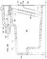
- FIG. 1is a schematic, perspective view, with a portion shown in cross section, of a reduced-pressure treatment system having a reduced-pressure canister according to an illustrative embodiment
- FIG. 2is a schematic, exploded, perspective view of the reduced-pressure canister of FIG. 1 ;
- FIG. 3Ais a schematic, side perspective view of the reduced-pressure canister of FIGS. 1-2 ;
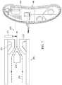
- FIG. 3Bis a schematic, side view of a portion of the of the reduced-pressure canister of FIG. 1-3A in cross section taken along line 3 B- 3 B of FIG. 3A ;
- FIG. 4is a schematic, side (interior) perspective view of a lid portion of the reduced-pressure canister of FIG. 1 ;
- FIG. 5Ais a schematic, detail view of a portion of a vent of a reduced-pressure canister
- FIG. 5Bis an alternative schematic, detail view of a portion of a vent of a reduced-pressure canister
- FIG. 5Cis an alternative schematic, detail view of a portion of a vent of a reduced-pressure canister
- FIG. 6Ais a schematic, partially-exploded, perspective view (interior facing) of a lid portion of a reduced-pressure canister having a grate member
- FIG. 6Bis a schematic detail of FIG. 6A ;
- FIG. 6Cis a schematic detail of FIG. 6A ;
- FIG. 7is a schematic diagram, with a portion shown as a perspective view, of a plasma treatment process for applying a hydrophobic coating to a vent portion of a reduced-pressure canister.
- tissue site 114 of a patientincludes a reduced-pressure delivery conduit 112 in fluid communication with a tissue site 114 of a patient.
- the tissue sitemay be a wound or defect located on or within any tissue, including but not limited to, bone tissue, adipose tissue, muscle tissue, neural tissue, dermal tissue, vascular tissue, connective tissue, cartilage, tendons, or ligaments.
- the tissue sitemay also be an area of any tissue, including wounded or defective as well as areas in which it is desired to add or promote the growth of additional tissue.
- the reduced-pressure treatment system 110may be used in certain tissue areas to grow additional tissue that may be harvested and transplanted to another tissue location.
- the reduced-pressure delivery conduit 112may fluidly communicate with the tissue site 114 through a tubing adapter 118 and a distribution manifold 122 .
- the distribution manifold 122may be any material, either bioabsorbable or non-bioabsorbable, if the material is capable of manifolding a reduced pressure to the tissue site 114 .
- the distribution manifold 122may be an open-cell, reticulated polyurethane foam.
- a drape 128may be placed over the distribution manifold 122 and sealed around a perimeter of the tissue site 114 to maintain reduced pressure at the tissue site 114 .
- a couplingprovides fluid communication between the reduced-pressure delivery conduit 112 and a reduced-pressure source 134 .
- the reduced-pressure source 134may be a reduced pressure or vacuum pump driven by a motor.
- the reduced-pressure sourcemay be a manually-actuated pump such as a compressible bellows pump.
- the reduced-pressure source 134may be a wall suction port such as are available in hospitals and other medical facilities.
- the reduced-pressure source 134may be housed within a reduced-pressure treatment unit 136 , which may also contain sensors, processing units, alarm indicators, memory, databases, software, display units, and user interfaces that further facilitate the application of reduced pressure treatment to the tissue site 114 .
- a sensor(not shown) may be disposed at or near the reduced-pressure source 134 to determine a source pressure generated by the reduced-pressure source 134 .
- the sensormay communicate with a processing unit that monitors and controls the reduced pressure delivered by the reduced-pressure source 134 .
- Delivery of reduced pressure to the tissue siteencourages new tissue growth by maintaining drainage of exudate from the tissue site, increasing blood flow to tissues surrounding the tissue site, and by compressing the distribution manifold into the tissue site, thereby creating microstrain at the tissue site which stimulates new tissue growth.
- a canister 137 having a canister body 142is fluidly coupled between the reduced-pressure source 134 and the tissue site 114 to collect exudate and other fluids drawn from the tissue site 114 .
- the canister 137may couple a reduced-pressure source 134 to a reduced-pressure manifold 122 at a tissue site 114 , and collect fluids from a wound at the tissue site 114 .
- the canister 137may be referred to as a reduced-pressure canister.
- the canister body 142includes a basin portion 144 and a lid portion 146 .
- the lid portion 146may be formed by a substantially planar exit wall 148 that is capable of mating with the basin portion 144 .
- a basin wall 150forms the basin portion 144 and includes curved contours to create a crescent shape.
- the basin portion 144 and lid portion 146may instead form a canister body that is cylindrical, cubical, rectangular cubical, or any other shape.
- the canister body 142may not include separate basin and lip portions, but rather may be formed from a substantially unitary housing.
- the canister body 142includes an inlet 152 fluidly coupled to the reduced-pressure delivery conduit 112 , and an outlet, or vent portion 160 .
- the reduced-pressure treatment system 110may include a canister filter or other in-line protection filter to prevent fluid from entering the reduced-pressure source 134 .
- the vent portion 160 of the canister body 142comprises a hydrophobic filter to prevent liquid from exiting the canister body 142 through the vent portion 160 .
- the inlet 152may be positioned on a wall 178 disposed in a recessed region 180 of the basin portion 144 .
- the hydrophobic filter of vent portion 160prevents liquid egress from the canister body 142 while allowing gases or vapor to exit.
- a hydrophobic filtermay be a hydrophobic membrane welded to the canister body 142 in a window or opening.
- a plurality of pores 162are formed in the canister body 142 and covered with a hydrophobic coating (e.g., hydrophobic coating 271 of FIG. 7 ) to form a weld-free hydrophobic filter.
- the vent portion 160includes the integral hydrophobic filter formed within the exit wall 148 . Integrating the vent portion 160 , which includes or otherwise functions as a hydrophobic filter, into the exit wall 148 may be beneficial for a number of reasons.
- An integral hydrophobic filterremoves the need to weld or fix a filter in place as a separate manufacturing step, thereby mitigating concerns related to welding a filter in place, using mechanical fasters, or using adhesives. Such concerns may include localized stresses, weaknesses associated with the weld(s), and material constraints associated with welded materials.
- an integral filtermay reduce the overall cost of the reduced-pressure canister because fewer parts and less labor are needed to assemble a canister body 142 for use in a reduced-pressure treatment system 110 or other medical system requiring a reduced-pressure canister.
- the vent portion 160allows fluid communication between the canister body 142 and the reduced-pressure source 134 such that a collection chamber or reservoir portion 166 formed by the canister body 142 can maintain a reduced pressure.
- This reduced pressuremay be transmitted to the tissue site (or other location for a medical application) through the inlet 152 .
- the inlet 152delivers the reduced pressure to the reduced-pressure delivery conduit 112 , the tubing adapter 118 , and the distribution manifold 122 .
- the reduced pressuredraws exudate and other fluids from the tissue site 114 into the canister body 142 .
- the hydrophobic filterprevents liquids that that are drawn into the canister body 142 from exiting the canister body 142 through the vent portion 160 and contaminating the reduced-pressure source 134 .
- the vent portion 160is formed with the plurality of pores 162 , or apertures, formed within the exit wall 148 , and a hydrophobic coating.
- the hydrophobic coatingmay be applied to the plurality of pores 162 to form the hydrophobic filter, which is integral to (i.e., formed within) the vent portion 160 and exit wall 148 . No welds are required.
- the integral hydrophobic filterenables the vent portion 160 to function as a liquid-air separator and prevent liquids from passing through the exit wall 148 to the reduced-pressure source 134 .
- the canister body 142includes the collection chamber 166 or fluid reservoir for collecting fluid within the canister body 142 .
- An entry chamber 170is positioned above the collection chamber 166 .
- An aperture 190allows fluid communication between the entry chamber 170 and the collection chamber 166 .
- the inlet 152may be disposed in the wall 178 such that a primary lumen of the reduced-pressure delivery conduit 112 facilitates communication between the tissue site 114 and the entry chamber 170 .
- the entry chamber 170further includes a floor 186 that at least partially separates the entry chamber 170 from the collection chamber 166 .
- the aperture 190may be a slot, hole, channel, or any other aperture that allows communication between the entry chamber 170 and the collection chamber 166 .
- the positions and shapes of the inlet 152 , vent portion 160 , and entry chamber 170may vary depending on the shape and configuration of the canister. As such, the positions and shapes of the inlet 152 , vent portion 160 , and entry chamber 170 may differ from the positioning, shapes, and general configurations described above and shown in the related FIGS. 1-7 .
- a baffle 156may be provided to reduce the formation of protein bubbles, burst protein bubbles that have formed, and minimize the premature blocking of the vent portion 160 .
- the baffle 156may have a surfactant coating to reduce the surface energy of the bubbles.
- FIG. 3Bshows the path of fluid entering the canister body 142 .
- Line 192schematically depicts the fluid path.
- the fluidpasses through the inlet 152 and into the entry chamber 170 . Fluid leaving the entry chamber 170 is directed downward (for the orientation shown) through the aperture 190 at an end of the entry chamber 170 .
- the fluidpasses into collection chamber 166 .
- gravitypulls any liquid in the fluid stream downward to collect in a bottom (for the orientation shown) portion of the collection chamber 166 . Gases in the fluid stream may be pulled upward around the baffle 156 to exit the canister body 142 at the vent portion 160 .
- the baffle 156creates a tortuous pathway (as illustrated, for example, by line 192 ) for fluid entering and traveling through the canister body 142 . This tortuous pathway minimizes the risk of premature blocking of the hydrophobic filter by liquid entering the canister body 142 . Additionally, the baffle 156 serves to prevent protein bubbles in the liquid exudate from forming or to block bubbles that have formed from reaching the vent portion 160 . The baffle 156 also prevents or substantially reduces line-of-sight between the entry chamber 170 and the vent portion 160 .
- a porous, reticulated foamsuch as a polyurethane foam may be positioned within the entry chamber 170 .
- the reticulated nature of the foamminimizes bubble formation near the open end of the entry chamber 170 , which limits protein deposition on the vent portion 160 .
- other foams or materialsmay be placed within the entry chamber 170 or between the entry chamber 170 and the vent portion 160 to prevent premature blocking of the hydrophobic filter.
- a porous foammay be placed anywhere in the canister to prevent or reduce protein deposition on the vent portion 160 .
- FIG. 4shows a vent portion 160 that may be formed on the inner surface of a lid portion 146 (or a wall) in a number of ways, as detailed in FIGS. 5A-5C .
- a plurality of pores 162are formed in a portion of the exit wall 148 of the lid portion 146 .
- the plurality of pores 162may be micro-drilled, and as such may be generally circular in shape.
- the exit wall 148is a part of the lid portion 146 of the canister body 142 and may be formed in an injection molding process.
- the exit wall 148is a flat area of accurate constant wall thickness where a filter can be located.
- vent portions 160include or form an integral hydrophobic filter, i.e., a hydrophobic filter formed within the exit wall 148 .
- the vent portion 160is formed from a plurality of pores 162 that are micro-holes formed in the exit wall 148 .
- the pores 162may be formed with an excimer laser or any other suitable manufacturing technique.
- the pores 162may also be formed by photo or chemical etching.
- the diameter (D) of each of the plurality of pores 162may be between 0.25 and 1 micron, or any other suitable size, and the quantity of pores 162 may be varied so that the cumulative flow rate through the pores 162 is sufficient for the flow of the system.
- the pores 162may be formed in a pattern or randomly.
- the pores 162may be sized to function as a barrier to bacteria or viruses.
- the plurality of pores 162may have a diameter of, for example, 0.5 to 1 microns.
- the plurality of pores 162may have a smaller diameter of, for example, 0.25 micron.
- the size of the poresmay even be adjusted to provide protection against specific types of bacteria. Generally, holes of 1 micron in diameter, arranged in a tortuous path, are sufficiently small to prevent the passage of some bacteria and fluid through a hydrophobic filter operated at low level differential pressures.
- FIG. 5Bpresents another illustrative embodiment in which the vent portion 160 is formed from a plurality of micro-slits 262 formed in the exit wall 148 instead of holes.
- the micro-slits 262are sized with a lateral gap such that the micro-slits 262 function analogously to pores 162 .
- the micro-slits 262may be formed using any technique mentioned herein for the pores or machining.
- FIG. 5Cpresents another illustrative embodiment that includes a separate grate member 364 that includes a second set of micro-slits 362 , also shown in FIG. 6 .
- the grate member 364may be formed separately from the exit wall 148 and affixed to the exit wall 148 such that the micro-slits 362 of the grate member 364 substantially overlie and are perpendicular to the micro-slits 262 of the exit wall 148 grate. In such a configuration, the intersections of the micro-slits 262 and 362 will create a set of micro-holes 363 that allow gases to pass through the vent portion 160 of the exit wall 148 .
- the micro-holes 363function analogously to the pores 162 .
- the entire vent portion 160may be formed in a grate member 364 that may be sealably coupled to an open area in an end wall 148 of a canister body 142 .
- Desired hydrophobic propertiesmay be given to the vent portion 160 by applying a surface treatment process to the vent portion 160 of the reduced-pressure canister over the apertures, e.g., pores 162 , micro-slits 262 , or micro-holes 363 .
- a surface treatment processis shown in FIG. 7 below.
- an illustrative lid portion 146 of a canister 137is presented with a plurality of micro-slits 262 formed in the exit wall 148 on a vent portion 160 .
- a grate member 364which has a plurality of micro-slits 362 as shown in FIG. 6C , is coupled to exit wall 148 over the micro-slits 262 to form a plurality of micro-holes analogous to micro-holes 363 of FIG. 5C .
- the plurality of holesmay be covered with a hydrophobic coating.
- a lid portion 146 of a reduced-pressure canisteris presented being treated in a plasma treatment chamber (not explicitly shown).
- a plasma coating unit 270receives a gas 272 and passes the gas 272 between a nozzle that includes a cathode 274 and anode 273 .
- An arc between the cathode 274 and anode 273ionizes the gas and causes the gas to dissociate and form a plasma stream 275 , into which the coating material 271 is injected.
- the plasma streamheats the coating material to a workable or depositable state.
- Other processes for delivering the hydrophobic coatingmay be used.
- the item to be coatedmay be placed within a chamber into which the treatment chemical is introduced and ionized.
- the heated plasma stream 275cools as the plasma stream 275 moves away from the plasma coating unit 270 .
- the work piecee.g., the canister lid portion 146
- the work piecee.g., the canister lid portion 146
- the coatingmay be a fluorocarbon, heptadecafluorodecylacylate, acrylates containing haloalkyl (e.g., fluoroalkyl) or perhaloalkyl (e.g.
- the hydrophobic coatingchemically bonds to the substrate, i.e., to the exit wall 148 of the lid portion 146 of the canister, to resist mobility or removal of the hydrophobic coating from the substrate.
- the reduced-pressure treatment unit 136may include a pressure sensor that monitors the pressure of the reduced-pressure treatment unit 136 .
- the hydrophobic filterprevents liquid from passing through the exit wall until the pressure differential between the fluid reservoir of the canister body 142 and the reduced-pressure treatment unit 136 reaches the breakthrough pressure of the filter, “P(b).”
- the reduced-pressure unitmay monitor the pressure differential between the canister body 142 and the reduced-pressure treatment unit 136 . Before the pressure differential reaches the breakthrough pressure, P(b), of the hydrophobic filter, the reduced-pressure treatment unit 136 may deactivate the reduced-pressure source, thereby preventing fluid from entering the reduced-pressure treatment unit 136 .
- the breakthrough pressure, P(b), of a hydrophobic filter resulting from the plasma treatment processis a function of the size of the holes that form the filter, the surface tension of the liquid, and the contact angle of the surface.
- the contact angle of the surfaceis a measure of the hydrophobicity of the surface.
- the hydrophobic filterhas a “water breakthrough pressure” of approximately 500 mm Hg.
- the deposited hydrophobic coatingmay advantageously show higher water repellence than more traditional PTFE based filters that provide an effective oleo-phobic or hydrophobic coating.
- Neutralizing odorsmay also be a concern when collecting fluids from a wound in a reduced-pressure treatment system.
- a charcoal filtermay be welded in place above the plurality of pores 162 on the internal face of the lid portion 146 of the canister body 142 . Use of the charcoal filter helps to ensure that air moved through the holes does not cause odor.
- a charcoal filtermay also be welded into the same location on the external sealing face of the canister body 142 .
- a charcoal coatingmay be applied to or included in a portion of the canister body 142 , which may include the vent portion, using a plasma surface treatment similar to the process described with regard to FIG. 7 .
- the canister body 142primarily collects exudate from the tissue site 114 or functions to collect liquid in other medical applications. Exudates from a small percentage of patients have unique chemical and physical properties. These properties promote bubble formation and foaming as fluid enters the canister, and the fluid may contain proteins that can adhere to many hydrophobic filter membranes. Under normal conditions, the protein film builds up gradually but protein film build-up may be exacerbated by the presence of foaming that causes the exudate to bubble. The presence of “exudate bubbles” maximizes the rate of protein adherence by atomizing minute droplets of protein-containing exudate when the bubbles pop. The small size of these droplets limits the liquid-shedding effects of the hydrophobic filter, and encourages their rapid evaporation.
- the vent portion 160may be coated with a protease during the plasma treatment process.
- the protease coatinghas the effects of an enzyme and may cause protein breakdown in the area of the filter to prevent build up and blockage of the filter.
- Such a coatingmay act as an anti-fouling layer in addition to preventing proteins from clogging the filter.
- an integral hydrophobic filteras an aspect of the vent portion 160
- other coatingsmay be applied to other portions of the canister body 142 by applying alternate coatings.
- other portions of the canister body 142may be coated with solidifying agents to stabilize or change the state of liquids that are collected in the canister body 142 .
- Such a coatingmay reduce the need for a super-absorbent pouch in some reduced-pressure treatment systems.
- the inside of a canister body 142may be coated with a bactericide that would kill or render bacteria inactive and reduce or eliminate odors.
- a charcoal coatingmay also be applied to reduce the need for the charcoal filter to eliminate odors.
- the reduced-pressure conduitmay be treated using a plasma treatment process so that fluids entering the conduit and canister body experience less drag when entering the canister.
- This type of coatingmay increase the efficiency of the tube and in turn increase the ability of the reduced-pressure treatment unit to function more accurately and efficiently.
- a hydrophobic filter that is integral to the canister body 142may have other beneficial attributes as compared to a welded filter or a filter assembled to the canister body using another manufacturing process. For example, a wider selection of materials may be available to form the filter because the material will not need to be welded. Further, the filter can be formed on surfaces that are less conducive to welding, allowing a filter to be easily formed within a curved canister wall. In the case of a welded filter, the weld may also present a point of weakness in the canister and a bad filter weld can result in the ingress of liquids to the reduced-pressure treatment unit.
- a plasma treatment process coatingmay also be “gamma stable,” i.e., able to withstand gamma radiation without being destabilized.
- Some materials used to create hydrophobic coatings, such as PTFEmay not be able to sustain gamma radiation without undergoing undesirable changes in their polymer structure.
- materials other than PTFEmay be more easily applied.
- heptadecafluorodecylacylatea more gamma stable polymer, may be applied using the plasma treatment process.
- a hydrophobic filter elementcan be made that withstands sterilization using gamma radiation without breaking down.
- the plasma coated solutionhas the beneficial attribute of being immobile once deposited.
- the applied coatingwill bond and coat the entire surface of the vent portion 160 , including the internal surfaces of micro-holes or other apertures that have been formed in the lid portion 146 (e.g., pores 162 ).
- the coated pores 162may provide an even greater repellence to liquid entry because the pores 162 will have a nominally smaller diameter, thereby increasing the breakthrough pressure, P(b), of the filter.
- P(b)breakthrough pressure
- the plasma treatment processcan be used to apply multiple coatings to apply different chemical groups, offering a plurality of functionality. As such, hydrophobic, hydrophilic, anti-protein, and anti-bacterial coatings may be applied.
- a method for forming a hydrophobic filter within a reduced-pressure canister bodyincludes forming a canister body 142 with a designated area to serve as a vent portion 160 .
- the methodalso includes perforating the designated area to populate the area with very small apertures, for example pores 162 having a diameter of between 0.25 and 1 microns.
- the methodinvolves applying a hydrophobic coating to the designated area as previously described.
- the hydrophobic coatingis a fluorocarbon, such as heptadecafluorodecylacylate.
- the integral hydrophobic filter of the canister bodyfunctions as both a fluid outlet and a liquid-air separator that allows gases to flow out of the canister but retains liquids within the canister.
- the methodmay include minimizing the susceptibility of the filter to occlusion resulting from the deposition of proteins from the wound exudate on the vent portion 160 .
- Minimization or prevention of protein depositionmay occur in several different ways, including by providing a baffle or porous foam, or by depositing a protease with the hydrophobic coating of the canister. In this way, protein deposition may further be minimized or prevented by preventing proteins from reaching the hydrophobic filter or by enzymatically breaking down any proteins that reach the filter.
- the illustrative embodiments described hereinmay be used with reduced-pressure treatment systems of any type, shape, or size and similarly with canisters of any type, shape, or size.
- the location of the inlet, outlet, and vent portion with an integral hydrophobic filtermay also vary depending upon the particular reduced-pressure canister design.
- the geometry of the vent portion and hydrophobic filtermay be modified as necessary to conform to the contours or configuration of the reduced-pressure canister.
- the vent portion and hydrophobic filterare not limited to use with a reduced-pressure treatment system.
- the vent portion and hydrophobic filtermay also be used with other medical collection canisters that include liquid-air separators.
Landscapes
- Health & Medical Sciences (AREA)
- Heart & Thoracic Surgery (AREA)
- Life Sciences & Earth Sciences (AREA)
- Engineering & Computer Science (AREA)
- Animal Behavior & Ethology (AREA)
- Biomedical Technology (AREA)
- Hematology (AREA)
- Anesthesiology (AREA)
- General Health & Medical Sciences (AREA)
- Public Health (AREA)
- Veterinary Medicine (AREA)
- Vascular Medicine (AREA)
- Wood Science & Technology (AREA)
- Otolaryngology (AREA)
- Media Introduction/Drainage Providing Device (AREA)
- External Artificial Organs (AREA)
Abstract
Description
Claims (17)
Priority Applications (1)
| Application Number | Priority Date | Filing Date | Title |
|---|---|---|---|
| US15/085,544US10980924B2 (en) | 2011-09-13 | 2016-03-30 | Reduced-pressure canisters having hydrophobic pores |
Applications Claiming Priority (3)
| Application Number | Priority Date | Filing Date | Title |
|---|---|---|---|
| US201161534232P | 2011-09-13 | 2011-09-13 | |
| US13/571,838US9327063B2 (en) | 2011-09-13 | 2012-08-10 | Reduced-pressure canisters having hydrophobic pores |
| US15/085,544US10980924B2 (en) | 2011-09-13 | 2016-03-30 | Reduced-pressure canisters having hydrophobic pores |
Related Parent Applications (1)
| Application Number | Title | Priority Date | Filing Date |
|---|---|---|---|
| US13/571,838DivisionUS9327063B2 (en) | 2011-09-13 | 2012-08-10 | Reduced-pressure canisters having hydrophobic pores |
Publications (2)
| Publication Number | Publication Date |
|---|---|
| US20160213822A1 US20160213822A1 (en) | 2016-07-28 |
| US10980924B2true US10980924B2 (en) | 2021-04-20 |
Family
ID=46727617
Family Applications (2)
| Application Number | Title | Priority Date | Filing Date |
|---|---|---|---|
| US13/571,838Active2033-05-18US9327063B2 (en) | 2011-09-13 | 2012-08-10 | Reduced-pressure canisters having hydrophobic pores |
| US15/085,544Active2033-09-03US10980924B2 (en) | 2011-09-13 | 2016-03-30 | Reduced-pressure canisters having hydrophobic pores |
Family Applications Before (1)
| Application Number | Title | Priority Date | Filing Date |
|---|---|---|---|
| US13/571,838Active2033-05-18US9327063B2 (en) | 2011-09-13 | 2012-08-10 | Reduced-pressure canisters having hydrophobic pores |
Country Status (7)
| Country | Link |
|---|---|
| US (2) | US9327063B2 (en) |
| EP (2) | EP3053609B1 (en) |
| JP (1) | JP6189845B2 (en) |
| CN (2) | CN103796692B (en) |
| AU (1) | AU2012309115B2 (en) |
| CA (1) | CA2844480C (en) |
| WO (1) | WO2013039623A1 (en) |
Families Citing this family (58)
| Publication number | Priority date | Publication date | Assignee | Title |
|---|---|---|---|---|
| US9526920B2 (en) | 2010-10-12 | 2016-12-27 | Smith & Nephew, Inc. | Medical device |
| WO2013066426A2 (en) | 2011-06-24 | 2013-05-10 | Kci Licensing, Inc. | Reduced-pressure dressings employing tissue-fixation elements |
| CN103796692B (en)* | 2011-09-13 | 2016-06-22 | 凯希特许有限公司 | Pressure Relief Tanks with Hydrophobic Pores |
| JP6250571B2 (en) | 2012-03-12 | 2017-12-20 | スミス アンド ネフュー ピーエルシーSmith & Nephew Public Limited Company | Pressure reducing apparatus and method |
| JP2016517318A (en) | 2013-03-14 | 2016-06-16 | スミス アンド ネフュー インコーポレーテッド | System and method for administering decompression therapy |
| US9737649B2 (en) | 2013-03-14 | 2017-08-22 | Smith & Nephew, Inc. | Systems and methods for applying reduced pressure therapy |
| USD764654S1 (en) | 2014-03-13 | 2016-08-23 | Smith & Nephew, Inc. | Canister for collecting wound exudate |
| WO2015023515A1 (en) | 2013-08-13 | 2015-02-19 | Smith & Nephew, Inc. | Systems and methods for applying reduced pressure therapy |
| US20150107603A1 (en)* | 2013-10-07 | 2015-04-23 | Apnicure, Inc. | Reservoir antechamber for reducing foaming during saliva collection |
| USD725768S1 (en)* | 2013-11-14 | 2015-03-31 | Human Design Medical, Llc | Flow generator |
| AU359280S (en)* | 2014-04-30 | 2014-12-08 | Talley Group Ltd | Negative pressure wound therapy pump |
| USD764047S1 (en) | 2014-05-28 | 2016-08-16 | Smith & Nephew, Inc. | Therapy unit assembly |
| USD764653S1 (en) | 2014-05-28 | 2016-08-23 | Smith & Nephew, Inc. | Canister for collecting wound exudate |
| USD764048S1 (en) | 2014-05-28 | 2016-08-16 | Smith & Nephew, Inc. | Device for applying negative pressure to a wound |
| USD770173S1 (en) | 2014-06-02 | 2016-11-01 | Smith & Nephew, Inc. | Bag |
| USD765830S1 (en) | 2014-06-02 | 2016-09-06 | Smith & Nephew, Inc. | Therapy unit assembly |
| CA3179001A1 (en) | 2014-07-31 | 2016-02-04 | Smith & Nephew, Inc. | Systems and methods for applying reduced pressure therapy |
| US12133789B2 (en) | 2014-07-31 | 2024-11-05 | Smith & Nephew, Inc. | Reduced pressure therapy apparatus construction and control |
| DK3288508T3 (en) | 2015-04-27 | 2020-03-09 | Smith & Nephew | REDUCED PRESSURE DEVICES |
| EP3297697B1 (en) | 2015-05-18 | 2022-05-11 | Smith & Nephew plc | Negative pressure wound therapy apparatus |
| AU2016305091B2 (en) | 2015-08-13 | 2021-06-10 | Smith & Nephew, Inc. | Systems and methods for applying reduced pressure therapy |
| EP3426206B1 (en) | 2016-03-07 | 2023-05-10 | Smith & Nephew plc | Wound treatment apparatuses and methods with negative pressure source integrated into wound dressing |
| CA3022184A1 (en) | 2016-04-26 | 2017-11-02 | Smith & Nephew Plc | Wound dressings and methods of use with integrated negative pressure source having a fluid ingress inhibition component |
| US11096831B2 (en) | 2016-05-03 | 2021-08-24 | Smith & Nephew Plc | Negative pressure wound therapy device activation and control |
| CA3038206A1 (en) | 2016-05-03 | 2017-11-09 | Smith & Nephew Plc | Optimizing power transfer to negative pressure sources in negative pressure therapy systems |
| WO2017191158A1 (en) | 2016-05-03 | 2017-11-09 | Smith & Nephew Plc | Systems and methods for driving negative pressure sources in negative pressure therapy systems |
| US11185624B2 (en)* | 2016-06-03 | 2021-11-30 | Kci Licensing, Inc. | Negative-pressure therapy with disposable instillation pump chamber |
| MX2019000232A (en) | 2016-07-08 | 2019-11-12 | Convatec Technologies Inc | Fluid flow sensing. |
| EP3481348A4 (en)* | 2016-07-08 | 2020-02-26 | ConvaTec Technologies Inc. | Fluid collection apparatus |
| DE102016115836A1 (en)* | 2016-08-25 | 2018-03-01 | Paul Hartmann Ag | Apparatus for the negative pressure treatment of wounds on the human body |
| WO2018037075A1 (en) | 2016-08-25 | 2018-03-01 | Smith & Nephew Plc | Absorbent negative pressure wound therapy dressing |
| EP3519001B1 (en) | 2016-09-30 | 2025-05-21 | Smith & Nephew plc | Negative pressure wound treatment apparatuses and methods with integrated electronics |
| EP3551244A1 (en) | 2016-12-12 | 2019-10-16 | Smith & Nephew PLC | Pressure wound therapy status indication via external device |
| US11395870B2 (en) | 2017-02-15 | 2022-07-26 | Smith & Nephew Asia Pacific Pte. Limited | Negative pressure wound therapy apparatuses and methods for using the same |
| EP3592312B1 (en) | 2017-03-08 | 2024-01-10 | Smith & Nephew plc | Negative pressure wound therapy device control in presence of fault condition |
| WO2018195101A1 (en) | 2017-04-19 | 2018-10-25 | Smith & Nephew, Inc. | Negative pressure wound therapy canisters |
| JP7121050B2 (en) | 2017-05-09 | 2022-08-17 | スミス アンド ネフュー ピーエルシー | Redundant control of negative pressure wound therapy systems |
| GB201718070D0 (en) | 2017-11-01 | 2017-12-13 | Smith & Nephew | Negative pressure wound treatment apparatuses and methods with integrated electronics |
| CA3074780A1 (en) | 2017-09-13 | 2019-03-21 | Smith & Nephew Plc | Negative pressure wound treatment apparatuses and methods with integrated electronics |
| EP3687592B1 (en) | 2017-09-29 | 2025-09-03 | T.J. Smith & Nephew, Limited | Negative pressure wound therapy apparatus with removable panels |
| GB201718054D0 (en) | 2017-11-01 | 2017-12-13 | Smith & Nephew | Sterilization of integrated negative pressure wound treatment apparatuses and sterilization methods |
| US11497653B2 (en) | 2017-11-01 | 2022-11-15 | Smith & Nephew Plc | Negative pressure wound treatment apparatuses and methods with integrated electronics |
| GB201718072D0 (en) | 2017-11-01 | 2017-12-13 | Smith & Nephew | Negative pressure wound treatment apparatuses and methods with integrated electronics |
| CN111836655A (en)* | 2017-11-16 | 2020-10-27 | 康沃特克有限公司 | fluid collection equipment |
| GB201813282D0 (en) | 2018-08-15 | 2018-09-26 | Smith & Nephew | System for medical device activation and opertion |
| GB201804347D0 (en) | 2018-03-19 | 2018-05-02 | Smith & Nephew Inc | Securing control of settings of negative pressure wound therapy apparatuses and methods for using the same |
| GB201806988D0 (en) | 2018-04-30 | 2018-06-13 | Quintanar Felix Clarence | Power source charging for negative pressure wound therapy apparatus |
| WO2019211731A1 (en) | 2018-04-30 | 2019-11-07 | Smith & Nephew Pte. Limited | Systems and methods for controlling dual mode negative pressure wound therapy apparatus |
| USD888225S1 (en) | 2018-04-30 | 2020-06-23 | Smith & Nephew Asia Pacific Pte. Limited | Pump and canister assembly for negative pressure wound therapy |
| GB201808438D0 (en) | 2018-05-23 | 2018-07-11 | Smith & Nephew | Systems and methods for determining blockages in a negative pressure wound therapy system |
| USD898925S1 (en) | 2018-09-13 | 2020-10-13 | Smith & Nephew Plc | Medical dressing |
| WO2020163313A1 (en)* | 2019-02-08 | 2020-08-13 | Kci Licensing, Inc. | Printed absorbent for use in wound fluid collection canisters |
| GB201903774D0 (en) | 2019-03-20 | 2019-05-01 | Smith & Nephew | Negative pressure wound treatment apparatuses and methods with integrated electronics |
| GB201907716D0 (en) | 2019-05-31 | 2019-07-17 | Smith & Nephew | Systems and methods for extending operational time of negative pressure wound treatment apparatuses |
| GB201914283D0 (en) | 2019-10-03 | 2019-11-20 | Smith & Nephew | Apparatuses and methods for negative pressure wound therapy |
| USD935033S1 (en) | 2020-03-05 | 2021-11-02 | Deroyal Industries, Inc. | Negative pressure wound therapy canister |
| USD935034S1 (en) | 2020-03-05 | 2021-11-02 | Deroyal Industries, Inc. | Negative pressure wound therapy canister |
| USD935035S1 (en) | 2020-03-05 | 2021-11-02 | Deroyal Industries, Inc. | Negative pressure wound therapy canister |
Citations (166)
| Publication number | Priority date | Publication date | Assignee | Title |
|---|---|---|---|---|
| US1355846A (en) | 1920-02-06 | 1920-10-19 | David A Rannells | Medical appliance |
| US2547758A (en) | 1949-01-05 | 1951-04-03 | Wilmer B Keeling | Instrument for treating the male urethra |
| US2632443A (en) | 1949-04-18 | 1953-03-24 | Eleanor P Lesher | Surgical dressing |
| GB692578A (en) | 1949-09-13 | 1953-06-10 | Minnesota Mining & Mfg | Improvements in or relating to drape sheets for surgical use |
| US2682873A (en) | 1952-07-30 | 1954-07-06 | Johnson & Johnson | General purpose protective dressing |
| US2910763A (en) | 1955-08-17 | 1959-11-03 | Du Pont | Felt-like products |
| US2969057A (en) | 1957-11-04 | 1961-01-24 | Brady Co W H | Nematodic swab |
| US3066672A (en) | 1960-09-27 | 1962-12-04 | Jr William H Crosby | Method and apparatus for serial sampling of intestinal juice |
| US3367332A (en) | 1965-08-27 | 1968-02-06 | Gen Electric | Product and process for establishing a sterile area of skin |
| US3520300A (en) | 1967-03-15 | 1970-07-14 | Amp Inc | Surgical sponge and suction device |
| US3568675A (en) | 1968-08-30 | 1971-03-09 | Clyde B Harvey | Fistula and penetrating wound dressing |
| US3648692A (en) | 1970-12-07 | 1972-03-14 | Parke Davis & Co | Medical-surgical dressing for burns and the like |
| US3682180A (en) | 1970-06-08 | 1972-08-08 | Coilform Co Inc | Drain clip for surgical drain |
| US3826254A (en) | 1973-02-26 | 1974-07-30 | Verco Ind | Needle or catheter retaining appliance |
| DE2640413A1 (en) | 1976-09-08 | 1978-03-09 | Wolf Gmbh Richard | CATHETER MONITORING DEVICE |
| US4080970A (en) | 1976-11-17 | 1978-03-28 | Miller Thomas J | Post-operative combination dressing and internal drain tube with external shield and tube connector |
| US4096853A (en) | 1975-06-21 | 1978-06-27 | Hoechst Aktiengesellschaft | Device for the introduction of contrast medium into an anus praeter |
| US4139004A (en) | 1977-02-17 | 1979-02-13 | Gonzalez Jr Harry | Bandage apparatus for treating burns |
| US4165748A (en) | 1977-11-07 | 1979-08-28 | Johnson Melissa C | Catheter tube holder |
| US4184510A (en) | 1977-03-15 | 1980-01-22 | Fibra-Sonics, Inc. | Valued device for controlling vacuum in surgery |
| WO1980002182A1 (en) | 1979-04-06 | 1980-10-16 | J Moss | Portable suction device for collecting fluids from a closed wound |
| US4233969A (en) | 1976-11-11 | 1980-11-18 | Lock Peter M | Wound dressing materials |
| US4245630A (en) | 1976-10-08 | 1981-01-20 | T. J. Smith & Nephew, Ltd. | Tearable composite strip of materials |
| US4256109A (en) | 1978-07-10 | 1981-03-17 | Nichols Robert L | Shut off valve for medical suction apparatus |
| US4261363A (en) | 1979-11-09 | 1981-04-14 | C. R. Bard, Inc. | Retention clips for body fluid drains |
| US4275721A (en) | 1978-11-28 | 1981-06-30 | Landstingens Inkopscentral Lic, Ekonomisk Forening | Vein catheter bandage |
| US4284079A (en) | 1979-06-28 | 1981-08-18 | Adair Edwin Lloyd | Method for applying a male incontinence device |
| US4297995A (en) | 1980-06-03 | 1981-11-03 | Key Pharmaceuticals, Inc. | Bandage containing attachment post |
| US4333468A (en) | 1980-08-18 | 1982-06-08 | Geist Robert W | Mesentery tube holder apparatus |
| US4373519A (en) | 1981-06-26 | 1983-02-15 | Minnesota Mining And Manufacturing Company | Composite wound dressing |
| US4382441A (en) | 1978-12-06 | 1983-05-10 | Svedman Paul | Device for treating tissues, for example skin |
| US4392858A (en) | 1981-07-16 | 1983-07-12 | Sherwood Medical Company | Wound drainage device |
| US4392853A (en) | 1981-03-16 | 1983-07-12 | Rudolph Muto | Sterile assembly for protecting and fastening an indwelling device |
| US4419097A (en) | 1981-07-31 | 1983-12-06 | Rexar Industries, Inc. | Attachment for catheter tube |
| EP0100148A1 (en) | 1982-07-06 | 1984-02-08 | Dow Corning Limited | Medical-surgical dressing and a process for the production thereof |
| US4465485A (en) | 1981-03-06 | 1984-08-14 | Becton, Dickinson And Company | Suction canister with unitary shut-off valve and filter features |
| EP0117632A2 (en) | 1983-01-27 | 1984-09-05 | Johnson & Johnson Products Inc. | Adhesive film dressing |
| US4475909A (en) | 1982-05-06 | 1984-10-09 | Eisenberg Melvin I | Male urinary device and method for applying the device |
| US4480638A (en) | 1980-03-11 | 1984-11-06 | Eduard Schmid | Cushion for holding an element of grafted skin |
| US4525374A (en) | 1984-02-27 | 1985-06-25 | Manresa, Inc. | Treating hydrophobic filters to render them hydrophilic |
| US4525166A (en) | 1981-11-21 | 1985-06-25 | Intermedicat Gmbh | Rolled flexible medical suction drainage device |
| US4540412A (en) | 1983-07-14 | 1985-09-10 | The Kendall Company | Device for moist heat therapy |
| US4543100A (en) | 1983-11-01 | 1985-09-24 | Brodsky Stuart A | Catheter and drain tube retainer |
| US4548202A (en) | 1983-06-20 | 1985-10-22 | Ethicon, Inc. | Mesh tissue fasteners |
| US4551139A (en) | 1982-02-08 | 1985-11-05 | Marion Laboratories, Inc. | Method and apparatus for burn wound treatment |
| EP0161865A2 (en) | 1984-05-03 | 1985-11-21 | Smith and Nephew Associated Companies p.l.c. | Adhesive wound dressing |
| US4569348A (en) | 1980-02-22 | 1986-02-11 | Velcro Usa Inc. | Catheter tube holder strap |
| AU550575B2 (en) | 1981-08-07 | 1986-03-27 | Richard Christian Wright | Wound drainage device |
| US4605399A (en) | 1984-12-04 | 1986-08-12 | Complex, Inc. | Transdermal infusion device |
| US4608041A (en) | 1981-10-14 | 1986-08-26 | Frese Nielsen | Device for treatment of wounds in body tissue of patients by exposure to jets of gas |
| US4640688A (en) | 1985-08-23 | 1987-02-03 | Mentor Corporation | Urine collection catheter |
| US4655754A (en) | 1984-11-09 | 1987-04-07 | Stryker Corporation | Vacuum wound drainage system and lipids baffle therefor |
| US4664662A (en) | 1984-08-02 | 1987-05-12 | Smith And Nephew Associated Companies Plc | Wound dressing |
| WO1987004626A1 (en) | 1986-01-31 | 1987-08-13 | Osmond, Roger, L., W. | Suction system for wound and gastro-intestinal drainage |
| US4710165A (en) | 1985-09-16 | 1987-12-01 | Mcneil Charles B | Wearable, variable rate suction/collection device |
| US4733659A (en) | 1986-01-17 | 1988-03-29 | Seton Company | Foam bandage |
| GB2195255A (en) | 1986-09-30 | 1988-04-07 | Vacutec Uk Limited | Method and apparatus for vacuum treatment of an epidermal surface |
| US4743232A (en) | 1986-10-06 | 1988-05-10 | The Clinipad Corporation | Package assembly for plastic film bandage |
| GB2197789A (en) | 1986-11-28 | 1988-06-02 | Smiths Industries Plc | Anti-foaming disinfectants used in surgical suction apparatus |
| US4758220A (en) | 1985-09-26 | 1988-07-19 | Alcon Laboratories, Inc. | Surgical cassette proximity sensing and latching apparatus |
| US4787888A (en) | 1987-06-01 | 1988-11-29 | University Of Connecticut | Disposable piezoelectric polymer bandage for percutaneous delivery of drugs and method for such percutaneous delivery (a) |
| US4826494A (en) | 1984-11-09 | 1989-05-02 | Stryker Corporation | Vacuum wound drainage system |
| US4838883A (en) | 1986-03-07 | 1989-06-13 | Nissho Corporation | Urine-collecting device |
| US4840187A (en) | 1986-09-11 | 1989-06-20 | Bard Limited | Sheath applicator |
| US4863449A (en) | 1987-07-06 | 1989-09-05 | Hollister Incorporated | Adhesive-lined elastic condom cathether |
| US4872450A (en) | 1984-08-17 | 1989-10-10 | Austad Eric D | Wound dressing and method of forming same |
| US4878901A (en) | 1986-10-10 | 1989-11-07 | Sachse Hans Ernst | Condom catheter, a urethral catheter for the prevention of ascending infections |
| GB2220357A (en) | 1988-05-28 | 1990-01-10 | Smiths Industries Plc | Medico-surgical containers |
| US4897081A (en) | 1984-05-25 | 1990-01-30 | Thermedics Inc. | Percutaneous access device |
| US4906240A (en) | 1988-02-01 | 1990-03-06 | Matrix Medica, Inc. | Adhesive-faced porous absorbent sheet and method of making same |
| US4906233A (en) | 1986-05-29 | 1990-03-06 | Terumo Kabushiki Kaisha | Method of securing a catheter body to a human skin surface |
| US4919654A (en) | 1988-08-03 | 1990-04-24 | Kalt Medical Corporation | IV clamp with membrane |
| US4930997A (en)* | 1987-08-19 | 1990-06-05 | Bennett Alan N | Portable medical suction device |
| CA2005436A1 (en) | 1988-12-13 | 1990-06-13 | Glenda G. Kalt | Transparent tracheostomy tube dressing |
| US4941882A (en) | 1987-03-14 | 1990-07-17 | Smith And Nephew Associated Companies, P.L.C. | Adhesive dressing for retaining a cannula on the skin |
| US4953565A (en) | 1986-11-26 | 1990-09-04 | Shunro Tachibana | Endermic application kits for external medicines |
| WO1990010424A1 (en) | 1989-03-16 | 1990-09-20 | Smith & Nephew Plc | Absorbent devices and precursors therefor |
| US4969880A (en) | 1989-04-03 | 1990-11-13 | Zamierowski David S | Wound dressing and treatment method |
| US4985019A (en) | 1988-03-11 | 1991-01-15 | Michelson Gary K | X-ray marker |
| GB2235877A (en) | 1989-09-18 | 1991-03-20 | Antonio Talluri | Closed wound suction apparatus |
| US5037397A (en) | 1985-05-03 | 1991-08-06 | Medical Distributors, Inc. | Universal clamp |
| US5086170A (en) | 1989-01-16 | 1992-02-04 | Roussel Uclaf | Process for the preparation of azabicyclo compounds |
| US5086764A (en)* | 1989-04-13 | 1992-02-11 | Thomas Gilman | Absorbent dressing |
| US5092858A (en) | 1990-03-20 | 1992-03-03 | Becton, Dickinson And Company | Liquid gelling agent distributor device |
| US5100396A (en) | 1989-04-03 | 1992-03-31 | Zamierowski David S | Fluidic connection system and method |
| US5134994A (en) | 1990-02-12 | 1992-08-04 | Say Sam L | Field aspirator in a soft pack with externally mounted container |
| US5149331A (en) | 1991-05-03 | 1992-09-22 | Ariel Ferdman | Method and device for wound closure |
| US5167613A (en) | 1992-03-23 | 1992-12-01 | The Kendall Company | Composite vented wound dressing |
| US5176663A (en) | 1987-12-02 | 1993-01-05 | Pal Svedman | Dressing having pad with compressibility limiting elements |
| WO1993009727A1 (en) | 1991-11-14 | 1993-05-27 | Wake Forest University | Method and apparatus for treating tissue damage |
| US5215522A (en) | 1984-07-23 | 1993-06-01 | Ballard Medical Products | Single use medical aspirating device and method |
| US5232453A (en) | 1989-07-14 | 1993-08-03 | E. R. Squibb & Sons, Inc. | Catheter holder |
| US5261893A (en) | 1989-04-03 | 1993-11-16 | Zamierowski David S | Fastening system and method |
| US5278100A (en) | 1991-11-08 | 1994-01-11 | Micron Technology, Inc. | Chemical vapor deposition technique for depositing titanium silicide on semiconductor wafers |
| US5279550A (en) | 1991-12-19 | 1994-01-18 | Gish Biomedical, Inc. | Orthopedic autotransfusion system |
| US5298015A (en) | 1989-07-11 | 1994-03-29 | Nippon Zeon Co., Ltd. | Wound dressing having a porous structure |
| US5342376A (en) | 1993-05-03 | 1994-08-30 | Dermagraphics, Inc. | Inserting device for a barbed tissue connector |
| US5344415A (en) | 1993-06-15 | 1994-09-06 | Deroyal Industries, Inc. | Sterile system for dressing vascular access site |
| DE4306478A1 (en) | 1993-03-02 | 1994-09-08 | Wolfgang Dr Wagner | Drainage device, in particular pleural drainage device, and drainage method |
| WO1994020041A1 (en) | 1993-03-09 | 1994-09-15 | Wake Forest University | Wound treatment employing reduced pressure |
| US5358494A (en) | 1989-07-11 | 1994-10-25 | Svedman Paul | Irrigation dressing |
| US5437622A (en) | 1992-04-29 | 1995-08-01 | Laboratoire Hydrex (Sa) | Transparent adhesive dressing with reinforced starter cuts |
| US5437651A (en) | 1993-09-01 | 1995-08-01 | Research Medical, Inc. | Medical suction apparatus |
| DE29504378U1 (en) | 1995-03-15 | 1995-09-14 | MTG Medizinisch, technische Gerätebau GmbH, 66299 Friedrichsthal | Electronically controlled low-vacuum pump for chest and wound drainage |
| US5466229A (en)* | 1993-08-06 | 1995-11-14 | Davstar, Inc. | Fluid collection system |
| WO1996005873A1 (en) | 1994-08-22 | 1996-02-29 | Kinetic Concepts Inc. | Wound drainage equipment |
| US5527293A (en) | 1989-04-03 | 1996-06-18 | Kinetic Concepts, Inc. | Fastening system and method |
| US5549584A (en) | 1994-02-14 | 1996-08-27 | The Kendall Company | Apparatus for removing fluid from a wound |
| US5556375A (en) | 1994-06-16 | 1996-09-17 | Hercules Incorporated | Wound dressing having a fenestrated base layer |
| US5607388A (en) | 1994-06-16 | 1997-03-04 | Hercules Incorporated | Multi-purpose wound dressing |
| WO1997018007A1 (en) | 1995-11-14 | 1997-05-22 | Kci Medical Limited | Portable wound treatment apparatus |
| GB2329127A (en) | 1997-09-12 | 1999-03-17 | Kci Medical Ltd | Suction head and drape wound treatment assembly |
| US6071267A (en) | 1998-02-06 | 2000-06-06 | Kinetic Concepts, Inc. | Medical patient fluid management interface system and method |
| US6135116A (en) | 1997-07-28 | 2000-10-24 | Kci Licensing, Inc. | Therapeutic method for treating ulcers |
| US6241747B1 (en) | 1993-05-03 | 2001-06-05 | Quill Medical, Inc. | Barbed Bodily tissue connector |
| US6287316B1 (en) | 1999-03-26 | 2001-09-11 | Ethicon, Inc. | Knitted surgical mesh |
| US20020077661A1 (en) | 2000-12-20 | 2002-06-20 | Vahid Saadat | Multi-barbed device for retaining tissue in apposition and methods of use |
| US20020115951A1 (en) | 2001-02-22 | 2002-08-22 | Core Products International, Inc. | Ankle brace providing upper and lower ankle adjustment |
| US20020120185A1 (en) | 2000-05-26 | 2002-08-29 | Kci Licensing, Inc. | System for combined transcutaneous blood gas monitoring and vacuum assisted wound closure |
| US20020143286A1 (en) | 2001-03-05 | 2002-10-03 | Kci Licensing, Inc. | Vacuum assisted wound treatment apparatus and infection identification system and method |
| US6488643B1 (en) | 1998-10-08 | 2002-12-03 | Kci Licensing, Inc. | Wound healing foot wrap |
| US6493568B1 (en) | 1994-07-19 | 2002-12-10 | Kci Licensing, Inc. | Patient interface system |
| AU755496B2 (en) | 1997-09-12 | 2002-12-12 | Kci Licensing, Inc. | Surgical drape and suction head for wound treatment |
| US20030153860A1 (en)* | 2000-07-18 | 2003-08-14 | Nielsen John Stern | Dressing |
| US6648862B2 (en)* | 2001-11-20 | 2003-11-18 | Spheric Products, Ltd. | Personally portable vacuum desiccator |
| US20040102743A1 (en)* | 1995-04-10 | 2004-05-27 | Walker Kenneth Gordon | System for disposal of fluids |
| JP2005131137A (en) | 2003-10-30 | 2005-05-26 | Toshiba Tec Corp | Electric vacuum cleaner |
| US7063688B2 (en)* | 2002-02-28 | 2006-06-20 | Say Family Trust | Portable battery operated aspirator |
| US7160273B2 (en)* | 2000-08-28 | 2007-01-09 | Medela Ag | Suction pump |
| US20070179460A1 (en)* | 2006-02-01 | 2007-08-02 | Carmeli Adahan | Suctioning system, method and kit |
| US20070202342A1 (en)* | 2005-12-12 | 2007-08-30 | Whiteford Jeffery A | Methods and systems for coating an oral surface |
| US20070272606A1 (en)* | 2006-05-25 | 2007-11-29 | Freese Donald T | Multi-functional coatings on microporous substrates |
| US20080082061A1 (en)* | 2006-09-28 | 2008-04-03 | Fei Pan | Draining Body Fluid from a Patient |
| US20080110822A1 (en)* | 2000-09-05 | 2008-05-15 | Donaldson Company, Inc. | Fine fiber media layer |
| JP4129536B2 (en) | 2000-02-24 | 2008-08-06 | ヴェネテック インターナショナル,インコーポレイテッド | Highly compatible catheter anchoring system |
| WO2009004291A2 (en) | 2007-07-02 | 2009-01-08 | Smith & Nephew Plc | Measuring pressure |
| WO2009004288A2 (en)* | 2007-07-02 | 2009-01-08 | Smith & Nephew Plc | Pressure control |
| WO2009019420A1 (en)* | 2007-08-06 | 2009-02-12 | Smith & Nephew Plc | Pump pressure control |
| WO2009019496A2 (en)* | 2007-08-06 | 2009-02-12 | Smith & Nephew Plc | Wound treatment apparatus able to distinguish between the fault conditions 'canister full' and 'aspirant conduit blocked' |
| US20090202739A1 (en)* | 2004-10-26 | 2009-08-13 | Dow Corning Ireland Ltd. | Method For Coating A Substrate Using Plasma |
| US20090221990A1 (en)* | 2008-02-29 | 2009-09-03 | Jonathan Paul Jaeb | System and method for collecting exudates |
| US20090254054A1 (en)* | 2002-10-28 | 2009-10-08 | Smith & Nephew Plc | Apparatus for aspirating, irrigating and cleansing wounds |
| US20100016767A1 (en)* | 2006-08-30 | 2010-01-21 | Jones Curtis E | Methods, Compositions and Apparatuses to Treat Wounds with Pressures Altered from Atmospheric |
| US20100063483A1 (en)* | 2007-05-07 | 2010-03-11 | Carmeli Adahan | Suction system |
| US7722582B2 (en)* | 1999-04-09 | 2010-05-25 | Kci Licensing, Inc. | Wound therapy device |
| US7722584B2 (en)* | 2006-06-28 | 2010-05-25 | Hitachi, Ltd. | Automatic urine collection apparatus |
| US20100305523A1 (en) | 2009-05-27 | 2010-12-02 | Tyco Healthcare Group Lp | Active Exudate Control System |
| US7846141B2 (en) | 2002-09-03 | 2010-12-07 | Bluesky Medical Group Incorporated | Reduced pressure treatment system |
| US7857806B2 (en)* | 2005-07-14 | 2010-12-28 | Boehringer Technologies, L.P. | Pump system for negative pressure wound therapy |
| US20110106027A1 (en) | 2009-11-05 | 2011-05-05 | Tyco Healthcare Group Lp | Chemically Coated Screen for Use with Hydrophobic Filters |
| US20110152799A1 (en) | 2009-12-23 | 2011-06-23 | Bendele Kevin | Reduced-pressure, multi-orientation, liquid-collection canister |
| US20110238004A1 (en)* | 2009-03-06 | 2011-09-29 | Bioquell Uk Limited | Improvements in or relating to wound treatment apparatus |
| US20110313373A1 (en)* | 2004-11-02 | 2011-12-22 | Birgit Riesinger | Device for the treatment of wounds using a vacuum |
| US8105295B2 (en)* | 2004-04-28 | 2012-01-31 | Smith & Nephew Plc | Dressing and apparatus for cleansing the wounds |
| US8216198B2 (en) | 2009-01-09 | 2012-07-10 | Tyco Healthcare Group Lp | Canister for receiving wound exudate in a negative pressure therapy system |
| US8240470B2 (en)* | 2007-07-02 | 2012-08-14 | Smith & Nephew Plc | Carrying bag |
| US8251979B2 (en) | 2009-05-11 | 2012-08-28 | Tyco Healthcare Group Lp | Orientation independent canister for a negative pressure wound therapy device |
| US8257327B2 (en) | 2003-10-28 | 2012-09-04 | Smith & Nephew Plc | Wound cleansing apparatus with actives |
| US8348910B2 (en)* | 2004-04-28 | 2013-01-08 | Smith & Nephew Plc | Apparatus for cleansing wounds with means for supply of thermal energy to the therapy fluid |
| US20130066301A1 (en)* | 2011-09-13 | 2013-03-14 | Christopher Brian Locke | Reduced-pressure canisters having hydrophobic pores |
| US8449509B2 (en) | 2004-04-05 | 2013-05-28 | Bluesky Medical Group Incorporated | Flexible reduced pressure treatment appliance |
| US8529548B2 (en) | 2004-04-27 | 2013-09-10 | Smith & Nephew Plc | Wound treatment apparatus and method |
| US8551060B2 (en) | 2008-07-17 | 2013-10-08 | Smith & Nephew, Inc. | Subatmospheric pressure mechanism for wound therapy system and related methods therefor |
| US8622981B2 (en)* | 2007-07-02 | 2014-01-07 | Smith & Nephew Plc | Modular wound treatment apparatus with releasable clip connection |
| US8926592B2 (en) | 2003-10-28 | 2015-01-06 | Smith & Nephew Plc | Wound cleansing apparatus with heat |
| US9017302B2 (en) | 2008-07-21 | 2015-04-28 | Smith & Nephew, Inc. | Thin film wound dressing |
Family Cites Families (6)
| Publication number | Priority date | Publication date | Assignee | Title |
|---|---|---|---|---|
| JP2001116334A (en)* | 1999-10-20 | 2001-04-27 | Ohbayashi Corp | Air outlet duct |
| US7004915B2 (en)* | 2001-08-24 | 2006-02-28 | Kci Licensing, Inc. | Negative pressure assisted tissue treatment system |
| AU2008219034B2 (en)* | 2007-02-20 | 2012-01-19 | Solventum Intellectual Properties Company | System and method for distinguishing leaks from a disengaged canister condition in a reduced pressure treatment system |
| EP2214612B1 (en) | 2007-11-21 | 2019-05-01 | Smith & Nephew PLC | Wound dressing |
| ES2715605T3 (en) | 2007-11-21 | 2019-06-05 | Smith & Nephew | Wound dressing |
| CA2984749C (en) | 2008-06-04 | 2020-06-23 | Kci Licensing, Inc. | Reduced-pressure, liquid-collection canister with multi-orientation filter |
- 2012
- 2012-08-10CNCN201280043930.4Apatent/CN103796692B/ennot_activeExpired - Fee Related
- 2012-08-10CNCN201610377561.2Apatent/CN106110411B/ennot_activeExpired - Fee Related
- 2012-08-10AUAU2012309115Apatent/AU2012309115B2/ennot_activeCeased
- 2012-08-10JPJP2014529726Apatent/JP6189845B2/ennot_activeExpired - Fee Related
- 2012-08-10USUS13/571,838patent/US9327063B2/enactiveActive
- 2012-08-10CACA2844480Apatent/CA2844480C/ennot_activeExpired - Fee Related
- 2012-08-10WOPCT/US2012/050369patent/WO2013039623A1/enactiveApplication Filing
- 2012-08-10EPEP16163004.1Apatent/EP3053609B1/ennot_activeRevoked
- 2012-08-10EPEP12750944.6Apatent/EP2755696B1/enactiveActive
- 2016
- 2016-03-30USUS15/085,544patent/US10980924B2/enactiveActive
Patent Citations (202)
| Publication number | Priority date | Publication date | Assignee | Title |
|---|---|---|---|---|
| US1355846A (en) | 1920-02-06 | 1920-10-19 | David A Rannells | Medical appliance |
| US2547758A (en) | 1949-01-05 | 1951-04-03 | Wilmer B Keeling | Instrument for treating the male urethra |
| US2632443A (en) | 1949-04-18 | 1953-03-24 | Eleanor P Lesher | Surgical dressing |
| GB692578A (en) | 1949-09-13 | 1953-06-10 | Minnesota Mining & Mfg | Improvements in or relating to drape sheets for surgical use |
| US2682873A (en) | 1952-07-30 | 1954-07-06 | Johnson & Johnson | General purpose protective dressing |
| US2910763A (en) | 1955-08-17 | 1959-11-03 | Du Pont | Felt-like products |
| US2969057A (en) | 1957-11-04 | 1961-01-24 | Brady Co W H | Nematodic swab |
| US3066672A (en) | 1960-09-27 | 1962-12-04 | Jr William H Crosby | Method and apparatus for serial sampling of intestinal juice |
| US3367332A (en) | 1965-08-27 | 1968-02-06 | Gen Electric | Product and process for establishing a sterile area of skin |
| US3520300A (en) | 1967-03-15 | 1970-07-14 | Amp Inc | Surgical sponge and suction device |
| US3568675A (en) | 1968-08-30 | 1971-03-09 | Clyde B Harvey | Fistula and penetrating wound dressing |
| US3682180A (en) | 1970-06-08 | 1972-08-08 | Coilform Co Inc | Drain clip for surgical drain |
| US3648692A (en) | 1970-12-07 | 1972-03-14 | Parke Davis & Co | Medical-surgical dressing for burns and the like |
| US3826254A (en) | 1973-02-26 | 1974-07-30 | Verco Ind | Needle or catheter retaining appliance |
| US4096853A (en) | 1975-06-21 | 1978-06-27 | Hoechst Aktiengesellschaft | Device for the introduction of contrast medium into an anus praeter |
| DE2640413A1 (en) | 1976-09-08 | 1978-03-09 | Wolf Gmbh Richard | CATHETER MONITORING DEVICE |
| US4245630A (en) | 1976-10-08 | 1981-01-20 | T. J. Smith & Nephew, Ltd. | Tearable composite strip of materials |
| US4233969A (en) | 1976-11-11 | 1980-11-18 | Lock Peter M | Wound dressing materials |
| US4080970A (en) | 1976-11-17 | 1978-03-28 | Miller Thomas J | Post-operative combination dressing and internal drain tube with external shield and tube connector |
| US4139004A (en) | 1977-02-17 | 1979-02-13 | Gonzalez Jr Harry | Bandage apparatus for treating burns |
| US4184510A (en) | 1977-03-15 | 1980-01-22 | Fibra-Sonics, Inc. | Valued device for controlling vacuum in surgery |
| US4165748A (en) | 1977-11-07 | 1979-08-28 | Johnson Melissa C | Catheter tube holder |
| US4256109A (en) | 1978-07-10 | 1981-03-17 | Nichols Robert L | Shut off valve for medical suction apparatus |
| US4275721A (en) | 1978-11-28 | 1981-06-30 | Landstingens Inkopscentral Lic, Ekonomisk Forening | Vein catheter bandage |
| US4382441A (en) | 1978-12-06 | 1983-05-10 | Svedman Paul | Device for treating tissues, for example skin |
| WO1980002182A1 (en) | 1979-04-06 | 1980-10-16 | J Moss | Portable suction device for collecting fluids from a closed wound |
| US4284079A (en) | 1979-06-28 | 1981-08-18 | Adair Edwin Lloyd | Method for applying a male incontinence device |
| US4261363A (en) | 1979-11-09 | 1981-04-14 | C. R. Bard, Inc. | Retention clips for body fluid drains |
| US4569348A (en) | 1980-02-22 | 1986-02-11 | Velcro Usa Inc. | Catheter tube holder strap |
| US4480638A (en) | 1980-03-11 | 1984-11-06 | Eduard Schmid | Cushion for holding an element of grafted skin |
| US4297995A (en) | 1980-06-03 | 1981-11-03 | Key Pharmaceuticals, Inc. | Bandage containing attachment post |
| US4333468A (en) | 1980-08-18 | 1982-06-08 | Geist Robert W | Mesentery tube holder apparatus |
| US4465485A (en) | 1981-03-06 | 1984-08-14 | Becton, Dickinson And Company | Suction canister with unitary shut-off valve and filter features |
| US4392853A (en) | 1981-03-16 | 1983-07-12 | Rudolph Muto | Sterile assembly for protecting and fastening an indwelling device |
| US4373519A (en) | 1981-06-26 | 1983-02-15 | Minnesota Mining And Manufacturing Company | Composite wound dressing |
| US4392858A (en) | 1981-07-16 | 1983-07-12 | Sherwood Medical Company | Wound drainage device |
| US4419097A (en) | 1981-07-31 | 1983-12-06 | Rexar Industries, Inc. | Attachment for catheter tube |
| AU550575B2 (en) | 1981-08-07 | 1986-03-27 | Richard Christian Wright | Wound drainage device |
| US4608041A (en) | 1981-10-14 | 1986-08-26 | Frese Nielsen | Device for treatment of wounds in body tissue of patients by exposure to jets of gas |
| US4525166A (en) | 1981-11-21 | 1985-06-25 | Intermedicat Gmbh | Rolled flexible medical suction drainage device |
| US4551139A (en) | 1982-02-08 | 1985-11-05 | Marion Laboratories, Inc. | Method and apparatus for burn wound treatment |
| US4475909A (en) | 1982-05-06 | 1984-10-09 | Eisenberg Melvin I | Male urinary device and method for applying the device |
| EP0100148A1 (en) | 1982-07-06 | 1984-02-08 | Dow Corning Limited | Medical-surgical dressing and a process for the production thereof |
| EP0117632A2 (en) | 1983-01-27 | 1984-09-05 | Johnson & Johnson Products Inc. | Adhesive film dressing |
| US4548202A (en) | 1983-06-20 | 1985-10-22 | Ethicon, Inc. | Mesh tissue fasteners |
| US4540412A (en) | 1983-07-14 | 1985-09-10 | The Kendall Company | Device for moist heat therapy |
| US4543100A (en) | 1983-11-01 | 1985-09-24 | Brodsky Stuart A | Catheter and drain tube retainer |
| US4525374A (en) | 1984-02-27 | 1985-06-25 | Manresa, Inc. | Treating hydrophobic filters to render them hydrophilic |
| EP0161865A2 (en) | 1984-05-03 | 1985-11-21 | Smith and Nephew Associated Companies p.l.c. | Adhesive wound dressing |
| US4897081A (en) | 1984-05-25 | 1990-01-30 | Thermedics Inc. | Percutaneous access device |
| US5215522A (en) | 1984-07-23 | 1993-06-01 | Ballard Medical Products | Single use medical aspirating device and method |
| US4664662A (en) | 1984-08-02 | 1987-05-12 | Smith And Nephew Associated Companies Plc | Wound dressing |
| US4872450A (en) | 1984-08-17 | 1989-10-10 | Austad Eric D | Wound dressing and method of forming same |
| US4655754A (en) | 1984-11-09 | 1987-04-07 | Stryker Corporation | Vacuum wound drainage system and lipids baffle therefor |
| US4826494A (en) | 1984-11-09 | 1989-05-02 | Stryker Corporation | Vacuum wound drainage system |
| US4605399A (en) | 1984-12-04 | 1986-08-12 | Complex, Inc. | Transdermal infusion device |
| US5037397A (en) | 1985-05-03 | 1991-08-06 | Medical Distributors, Inc. | Universal clamp |
| US4640688A (en) | 1985-08-23 | 1987-02-03 | Mentor Corporation | Urine collection catheter |
| US4710165A (en) | 1985-09-16 | 1987-12-01 | Mcneil Charles B | Wearable, variable rate suction/collection device |
| US4758220A (en) | 1985-09-26 | 1988-07-19 | Alcon Laboratories, Inc. | Surgical cassette proximity sensing and latching apparatus |
| US4733659A (en) | 1986-01-17 | 1988-03-29 | Seton Company | Foam bandage |
| WO1987004626A1 (en) | 1986-01-31 | 1987-08-13 | Osmond, Roger, L., W. | Suction system for wound and gastro-intestinal drainage |
| US4838883A (en) | 1986-03-07 | 1989-06-13 | Nissho Corporation | Urine-collecting device |
| US4906233A (en) | 1986-05-29 | 1990-03-06 | Terumo Kabushiki Kaisha | Method of securing a catheter body to a human skin surface |
| US4840187A (en) | 1986-09-11 | 1989-06-20 | Bard Limited | Sheath applicator |
| GB2195255A (en) | 1986-09-30 | 1988-04-07 | Vacutec Uk Limited | Method and apparatus for vacuum treatment of an epidermal surface |
| US4743232A (en) | 1986-10-06 | 1988-05-10 | The Clinipad Corporation | Package assembly for plastic film bandage |
| US4878901A (en) | 1986-10-10 | 1989-11-07 | Sachse Hans Ernst | Condom catheter, a urethral catheter for the prevention of ascending infections |
| US4953565A (en) | 1986-11-26 | 1990-09-04 | Shunro Tachibana | Endermic application kits for external medicines |
| GB2197789A (en) | 1986-11-28 | 1988-06-02 | Smiths Industries Plc | Anti-foaming disinfectants used in surgical suction apparatus |
| US4941882A (en) | 1987-03-14 | 1990-07-17 | Smith And Nephew Associated Companies, P.L.C. | Adhesive dressing for retaining a cannula on the skin |
| US4787888A (en) | 1987-06-01 | 1988-11-29 | University Of Connecticut | Disposable piezoelectric polymer bandage for percutaneous delivery of drugs and method for such percutaneous delivery (a) |
| US4863449A (en) | 1987-07-06 | 1989-09-05 | Hollister Incorporated | Adhesive-lined elastic condom cathether |
| US4930997A (en)* | 1987-08-19 | 1990-06-05 | Bennett Alan N | Portable medical suction device |
| US5176663A (en) | 1987-12-02 | 1993-01-05 | Pal Svedman | Dressing having pad with compressibility limiting elements |
| US4906240A (en) | 1988-02-01 | 1990-03-06 | Matrix Medica, Inc. | Adhesive-faced porous absorbent sheet and method of making same |
| US4985019A (en) | 1988-03-11 | 1991-01-15 | Michelson Gary K | X-ray marker |
| EP0358302A2 (en) | 1988-05-28 | 1990-03-14 | Smiths Industries Public Limited Company | Medico-surgical suction container |
| GB2220357A (en) | 1988-05-28 | 1990-01-10 | Smiths Industries Plc | Medico-surgical containers |
| US4919654A (en) | 1988-08-03 | 1990-04-24 | Kalt Medical Corporation | IV clamp with membrane |
| CA2005436A1 (en) | 1988-12-13 | 1990-06-13 | Glenda G. Kalt | Transparent tracheostomy tube dressing |
| US5086170A (en) | 1989-01-16 | 1992-02-04 | Roussel Uclaf | Process for the preparation of azabicyclo compounds |
| WO1990010424A1 (en) | 1989-03-16 | 1990-09-20 | Smith & Nephew Plc | Absorbent devices and precursors therefor |
| US4969880A (en) | 1989-04-03 | 1990-11-13 | Zamierowski David S | Wound dressing and treatment method |
| US5261893A (en) | 1989-04-03 | 1993-11-16 | Zamierowski David S | Fastening system and method |
| US5100396A (en) | 1989-04-03 | 1992-03-31 | Zamierowski David S | Fluidic connection system and method |
| US5527293A (en) | 1989-04-03 | 1996-06-18 | Kinetic Concepts, Inc. | Fastening system and method |
| US5086764A (en)* | 1989-04-13 | 1992-02-11 | Thomas Gilman | Absorbent dressing |
| US5358494A (en) | 1989-07-11 | 1994-10-25 | Svedman Paul | Irrigation dressing |
| US5298015A (en) | 1989-07-11 | 1994-03-29 | Nippon Zeon Co., Ltd. | Wound dressing having a porous structure |
| US5232453A (en) | 1989-07-14 | 1993-08-03 | E. R. Squibb & Sons, Inc. | Catheter holder |
| GB2235877A (en) | 1989-09-18 | 1991-03-20 | Antonio Talluri | Closed wound suction apparatus |
| US5134994A (en) | 1990-02-12 | 1992-08-04 | Say Sam L | Field aspirator in a soft pack with externally mounted container |
| US5092858A (en) | 1990-03-20 | 1992-03-03 | Becton, Dickinson And Company | Liquid gelling agent distributor device |
| US5149331A (en) | 1991-05-03 | 1992-09-22 | Ariel Ferdman | Method and device for wound closure |
| US5278100A (en) | 1991-11-08 | 1994-01-11 | Micron Technology, Inc. | Chemical vapor deposition technique for depositing titanium silicide on semiconductor wafers |
| WO1993009727A1 (en) | 1991-11-14 | 1993-05-27 | Wake Forest University | Method and apparatus for treating tissue damage |
| US5645081A (en) | 1991-11-14 | 1997-07-08 | Wake Forest University | Method of treating tissue damage and apparatus for same |
| US5636643A (en) | 1991-11-14 | 1997-06-10 | Wake Forest University | Wound treatment employing reduced pressure |
| US5279550A (en) | 1991-12-19 | 1994-01-18 | Gish Biomedical, Inc. | Orthopedic autotransfusion system |
| US5167613A (en) | 1992-03-23 | 1992-12-01 | The Kendall Company | Composite vented wound dressing |
| US5437622A (en) | 1992-04-29 | 1995-08-01 | Laboratoire Hydrex (Sa) | Transparent adhesive dressing with reinforced starter cuts |
| DE4306478A1 (en) | 1993-03-02 | 1994-09-08 | Wolfgang Dr Wagner | Drainage device, in particular pleural drainage device, and drainage method |
| WO1994020041A1 (en) | 1993-03-09 | 1994-09-15 | Wake Forest University | Wound treatment employing reduced pressure |
| US6241747B1 (en) | 1993-05-03 | 2001-06-05 | Quill Medical, Inc. | Barbed Bodily tissue connector |
| US5342376A (en) | 1993-05-03 | 1994-08-30 | Dermagraphics, Inc. | Inserting device for a barbed tissue connector |
| US5344415A (en) | 1993-06-15 | 1994-09-06 | Deroyal Industries, Inc. | Sterile system for dressing vascular access site |
| US5466229A (en)* | 1993-08-06 | 1995-11-14 | Davstar, Inc. | Fluid collection system |
| US5437651A (en) | 1993-09-01 | 1995-08-01 | Research Medical, Inc. | Medical suction apparatus |
| US5549584A (en) | 1994-02-14 | 1996-08-27 | The Kendall Company | Apparatus for removing fluid from a wound |
| US5607388A (en) | 1994-06-16 | 1997-03-04 | Hercules Incorporated | Multi-purpose wound dressing |
| US5556375A (en) | 1994-06-16 | 1996-09-17 | Hercules Incorporated | Wound dressing having a fenestrated base layer |
| US6493568B1 (en) | 1994-07-19 | 2002-12-10 | Kci Licensing, Inc. | Patient interface system |
| WO1996005873A1 (en) | 1994-08-22 | 1996-02-29 | Kinetic Concepts Inc. | Wound drainage equipment |
| US7611500B1 (en)* | 1994-08-22 | 2009-11-03 | Kci Licensing, Inc. | Wound therapy device and related methods |
| DE29504378U1 (en) | 1995-03-15 | 1995-09-14 | MTG Medizinisch, technische Gerätebau GmbH, 66299 Friedrichsthal | Electronically controlled low-vacuum pump for chest and wound drainage |
| US20080281283A1 (en) | 1995-04-10 | 2008-11-13 | Kenneth Gordon Walker | System for disposal of fluids |
| US20040102743A1 (en)* | 1995-04-10 | 2004-05-27 | Walker Kenneth Gordon | System for disposal of fluids |
| US7670323B2 (en) | 1995-11-14 | 2010-03-02 | Kci Licensing, Inc. | Portable wound treatment apparatus having pressure feedback capabilities |
| US7316672B1 (en) | 1995-11-14 | 2008-01-08 | Kci Licensing, Inc. | Portable wound treatment apparatus |
| US20070167927A1 (en) | 1995-11-14 | 2007-07-19 | Kci Licensing, Inc. | Portable wound treatment apparatus having pressure feedback capabilities |
| WO1997018007A1 (en) | 1995-11-14 | 1997-05-22 | Kci Medical Limited | Portable wound treatment apparatus |
| US6142982A (en)* | 1995-11-14 | 2000-11-07 | Kci Medical Limited | Portable wound treatment apparatus |
| US6135116A (en) | 1997-07-28 | 2000-10-24 | Kci Licensing, Inc. | Therapeutic method for treating ulcers |
| US6814079B2 (en) | 1997-09-12 | 2004-11-09 | Kci Licensing, Inc. | Surgical drape and suction head for wound treatment |
| EP1018967A1 (en) | 1997-09-12 | 2000-07-19 | KCI Medical Ltd. | Surgical drape and suction head for wound treatment |
| GB2329127A (en) | 1997-09-12 | 1999-03-17 | Kci Medical Ltd | Suction head and drape wound treatment assembly |
| WO1999013793A1 (en) | 1997-09-12 | 1999-03-25 | Kci Medical Limited | Surgical drape and suction head for wound treatment |
| GB2333965A (en) | 1997-09-12 | 1999-08-11 | Kci Medical Ltd | Surgical drape |
| US6345623B1 (en) | 1997-09-12 | 2002-02-12 | Keith Patrick Heaton | Surgical drape and suction head for wound treatment |
| AU745271B2 (en) | 1997-09-12 | 2002-03-14 | Kci Licensing, Inc. | Surgical drape and suction head for wound treatment |
| AU755496B2 (en) | 1997-09-12 | 2002-12-12 | Kci Licensing, Inc. | Surgical drape and suction head for wound treatment |
| US6553998B2 (en) | 1997-09-12 | 2003-04-29 | Kci Licensing, Inc. | Surgical drape and suction head for wound treatment |
| US6071267A (en) | 1998-02-06 | 2000-06-06 | Kinetic Concepts, Inc. | Medical patient fluid management interface system and method |
| US6488643B1 (en) | 1998-10-08 | 2002-12-03 | Kci Licensing, Inc. | Wound healing foot wrap |
| US6287316B1 (en) | 1999-03-26 | 2001-09-11 | Ethicon, Inc. | Knitted surgical mesh |
| US7758554B2 (en) | 1999-04-09 | 2010-07-20 | Kci Licensing, Inc. | Reduced pressure treatment system having a dual porosity pad |
| US7722582B2 (en)* | 1999-04-09 | 2010-05-25 | Kci Licensing, Inc. | Wound therapy device |
| JP4129536B2 (en) | 2000-02-24 | 2008-08-06 | ヴェネテック インターナショナル,インコーポレイテッド | Highly compatible catheter anchoring system |
| US20020120185A1 (en) | 2000-05-26 | 2002-08-29 | Kci Licensing, Inc. | System for combined transcutaneous blood gas monitoring and vacuum assisted wound closure |
| US20030153860A1 (en)* | 2000-07-18 | 2003-08-14 | Nielsen John Stern | Dressing |
| US7619130B2 (en) | 2000-07-18 | 2009-11-17 | Coloplast A/S | Multi-layer wound dressing formed as a single unit |
| US7160273B2 (en)* | 2000-08-28 | 2007-01-09 | Medela Ag | Suction pump |
| US20080110822A1 (en)* | 2000-09-05 | 2008-05-15 | Donaldson Company, Inc. | Fine fiber media layer |
| US20020077661A1 (en) | 2000-12-20 | 2002-06-20 | Vahid Saadat | Multi-barbed device for retaining tissue in apposition and methods of use |
| US20020115951A1 (en) | 2001-02-22 | 2002-08-22 | Core Products International, Inc. | Ankle brace providing upper and lower ankle adjustment |
| US20020143286A1 (en) | 2001-03-05 | 2002-10-03 | Kci Licensing, Inc. | Vacuum assisted wound treatment apparatus and infection identification system and method |
| USRE42834E1 (en) | 2001-11-20 | 2011-10-11 | Kci Licensing Inc. | Personally portable vacuum desiccator |
| US6648862B2 (en)* | 2001-11-20 | 2003-11-18 | Spheric Products, Ltd. | Personally portable vacuum desiccator |
| US7063688B2 (en)* | 2002-02-28 | 2006-06-20 | Say Family Trust | Portable battery operated aspirator |
| US8062273B2 (en) | 2002-09-03 | 2011-11-22 | Bluesky Medical Group Incorporated | Reduced pressure treatment system |
| US9211365B2 (en) | 2002-09-03 | 2015-12-15 | Bluesky Medical Group, Inc. | Reduced pressure treatment system |
| US7846141B2 (en) | 2002-09-03 | 2010-12-07 | Bluesky Medical Group Incorporated | Reduced pressure treatment system |
| US8398614B2 (en) | 2002-10-28 | 2013-03-19 | Smith & Nephew Plc | Apparatus for aspirating, irrigating and cleansing wounds |
| US20090254054A1 (en)* | 2002-10-28 | 2009-10-08 | Smith & Nephew Plc | Apparatus for aspirating, irrigating and cleansing wounds |
| US8535296B2 (en) | 2002-10-28 | 2013-09-17 | Smith & Nephew Plc | Apparatus for aspirating, irrigating and cleansing wounds |
| US8834451B2 (en) | 2002-10-28 | 2014-09-16 | Smith & Nephew Plc | In-situ wound cleansing apparatus |
| US8926592B2 (en) | 2003-10-28 | 2015-01-06 | Smith & Nephew Plc | Wound cleansing apparatus with heat |
| US9289542B2 (en) | 2003-10-28 | 2016-03-22 | Smith & Nephew Plc | Wound cleansing apparatus |
| US8257327B2 (en) | 2003-10-28 | 2012-09-04 | Smith & Nephew Plc | Wound cleansing apparatus with actives |
| JP2005131137A (en) | 2003-10-30 | 2005-05-26 | Toshiba Tec Corp | Electric vacuum cleaner |
| US9198801B2 (en) | 2004-04-05 | 2015-12-01 | Bluesky Medical Group, Inc. | Flexible reduced pressure treatment appliance |
| US8449509B2 (en) | 2004-04-05 | 2013-05-28 | Bluesky Medical Group Incorporated | Flexible reduced pressure treatment appliance |
| US20150080788A1 (en) | 2004-04-27 | 2015-03-19 | Smith & Nephew Plc | Wound treatment apparatus and method |
| US8529548B2 (en) | 2004-04-27 | 2013-09-10 | Smith & Nephew Plc | Wound treatment apparatus and method |
| US8348910B2 (en)* | 2004-04-28 | 2013-01-08 | Smith & Nephew Plc | Apparatus for cleansing wounds with means for supply of thermal energy to the therapy fluid |
| US8105295B2 (en)* | 2004-04-28 | 2012-01-31 | Smith & Nephew Plc | Dressing and apparatus for cleansing the wounds |
| US20090202739A1 (en)* | 2004-10-26 | 2009-08-13 | Dow Corning Ireland Ltd. | Method For Coating A Substrate Using Plasma |
| US20110313373A1 (en)* | 2004-11-02 | 2011-12-22 | Birgit Riesinger | Device for the treatment of wounds using a vacuum |
| US7857806B2 (en)* | 2005-07-14 | 2010-12-28 | Boehringer Technologies, L.P. | Pump system for negative pressure wound therapy |
| US20070202342A1 (en)* | 2005-12-12 | 2007-08-30 | Whiteford Jeffery A | Methods and systems for coating an oral surface |
| US20080020127A1 (en)* | 2005-12-12 | 2008-01-24 | Allaccem, Inc. | Methods and systems for coating a medical device |
| US8235972B2 (en) | 2006-02-01 | 2012-08-07 | Carmeli Adahan | Suctioning system, method and kit |
| US20070179460A1 (en)* | 2006-02-01 | 2007-08-02 | Carmeli Adahan | Suctioning system, method and kit |
| US7503910B2 (en) | 2006-02-01 | 2009-03-17 | Carmeli Adahan | Suctioning system, method and kit |
| US20090198201A1 (en) | 2006-02-01 | 2009-08-06 | Carmeli Adahan | Suctioning system, method and kit |
| US20070272606A1 (en)* | 2006-05-25 | 2007-11-29 | Freese Donald T | Multi-functional coatings on microporous substrates |
| US7722584B2 (en)* | 2006-06-28 | 2010-05-25 | Hitachi, Ltd. | Automatic urine collection apparatus |
| US20100016767A1 (en)* | 2006-08-30 | 2010-01-21 | Jones Curtis E | Methods, Compositions and Apparatuses to Treat Wounds with Pressures Altered from Atmospheric |
| US20080082061A1 (en)* | 2006-09-28 | 2008-04-03 | Fei Pan | Draining Body Fluid from a Patient |
| US8317774B2 (en) | 2007-05-07 | 2012-11-27 | Carmeli Adahan | Suction system |
| US20100063483A1 (en)* | 2007-05-07 | 2010-03-11 | Carmeli Adahan | Suction system |
| US8240470B2 (en)* | 2007-07-02 | 2012-08-14 | Smith & Nephew Plc | Carrying bag |
| US20110008179A1 (en)* | 2007-07-02 | 2011-01-13 | Smith & Nephew Plc | Pressure control |
| WO2009004288A2 (en)* | 2007-07-02 | 2009-01-08 | Smith & Nephew Plc | Pressure control |
| US8622981B2 (en)* | 2007-07-02 | 2014-01-07 | Smith & Nephew Plc | Modular wound treatment apparatus with releasable clip connection |
| WO2009004291A2 (en) | 2007-07-02 | 2009-01-08 | Smith & Nephew Plc | Measuring pressure |
| WO2009019496A2 (en)* | 2007-08-06 | 2009-02-12 | Smith & Nephew Plc | Wound treatment apparatus able to distinguish between the fault conditions 'canister full' and 'aspirant conduit blocked' |
| WO2009019420A1 (en)* | 2007-08-06 | 2009-02-12 | Smith & Nephew Plc | Pump pressure control |
| US20090221990A1 (en)* | 2008-02-29 | 2009-09-03 | Jonathan Paul Jaeb | System and method for collecting exudates |
| US8551060B2 (en) | 2008-07-17 | 2013-10-08 | Smith & Nephew, Inc. | Subatmospheric pressure mechanism for wound therapy system and related methods therefor |
| US20140163491A1 (en) | 2008-07-17 | 2014-06-12 | Smith & Nephew, Inc. | Subatmospheric pressure mechanism for wound therapy system and related methods therefor |
| US9017302B2 (en) | 2008-07-21 | 2015-04-28 | Smith & Nephew, Inc. | Thin film wound dressing |
| US8679081B2 (en) | 2009-01-09 | 2014-03-25 | Smith & Nephew, Inc. | Canister for receiving wound exudate in a negative pressure therapy system |
| US8216198B2 (en) | 2009-01-09 | 2012-07-10 | Tyco Healthcare Group Lp | Canister for receiving wound exudate in a negative pressure therapy system |
| US20110238004A1 (en)* | 2009-03-06 | 2011-09-29 | Bioquell Uk Limited | Improvements in or relating to wound treatment apparatus |
| US8568386B2 (en) | 2009-05-11 | 2013-10-29 | Smith & Nephew, Inc. | Orientation independent canister for a negative pressure wound therapy device |
| US8251979B2 (en) | 2009-05-11 | 2012-08-28 | Tyco Healthcare Group Lp | Orientation independent canister for a negative pressure wound therapy device |
| US20100305523A1 (en) | 2009-05-27 | 2010-12-02 | Tyco Healthcare Group Lp | Active Exudate Control System |
| US20110106027A1 (en) | 2009-11-05 | 2011-05-05 | Tyco Healthcare Group Lp | Chemically Coated Screen for Use with Hydrophobic Filters |
| US20110152799A1 (en) | 2009-12-23 | 2011-06-23 | Bendele Kevin | Reduced-pressure, multi-orientation, liquid-collection canister |
| US20130066301A1 (en)* | 2011-09-13 | 2013-03-14 | Christopher Brian Locke | Reduced-pressure canisters having hydrophobic pores |
Non-Patent Citations (42)
| Title |
|---|
| A.A. Safronov, Dissertation Abstract, Vacuum Therapy of Trophic Ulcers of the Lower Leg with Simultaneous Autoplasty of the Skin (Central Scientific Research Institute of Traumatology and Orthopedics, Moscow, U.S.S.R. 1967) (copy and certified translation). |
| Arnljots, Björn et al.: "Irrigation Treatment in Split-Thickness Skin Grafting of Intractable Leg Ulcers", Scand J. Plast Reconstr. Surg., No. 19, 1985, pp. 211-213. |
| C.E. Tennants, "The Use of Hypermia in the Postoperative Treatment of Lesions of the Extremities and Thorax," Journal of the American Medical Association 64 (1915), pp. 1548-1549. |
| Chariker, Mark E., M.D., et al; "Effective Management of incisional and cutaneous fistulae with closed suction wound drainage"; Contemporary Surgery, vol. 34, Jun. 1989, pp. 59-63. |
| Chinn, Steven D. et al: "Closed Wound Suction Drainage", The Journal of Foot Surgery, vol. 24, No. 1, 1985, pp. 76-81. |
| D.E. Tribble, An Improved Sump Drain-Irrigation Device of Simple Construction, Archives of Surgery 105 (1972) pp. 511-513. |
| Dattilo, Philip P., Jr., et al; "Medical Textiles: Application of an Absorbable Barbed Bi-directional Surgical Suture"; Journal of Textile and Apparel, Technology and Management, vol. 2, Issue 2, Spring 2002, pp. 1-5. |
| Davydov, Yu. A., et al; "Vacuum Therapy in the Treatment of Purulent Lactation Mastitis"; Vestnik Khirurgi, May 14, 1986, pp. 66-70, and 9 page English translation thereof. |
| Davydov, Yu.A., et al; "Bacteriological and Cytological Assessment of Vacuum Therapy for Purulent Wounds"; Vestnik Khirugi, Oct. 1988, pp: 48-52, and 8 page English translation thereof. |
| Davydov, Yu.A., et al; "Concepts for the Clinical-Biological Management of the Wound Process in the Treatment of Purulent Wounds by Means of Vacuum Therapy"; Vestnik Khirurgi, Jul. 7, 1980, pp. 132-136, and 8 page English translation thereof. |
| Egnell Minor, Instruction Book, First Edition, 300 7502, Feb. 1975, pp. 24. |
| Egnell Minor: Addition to the Users Manual Concerning Overflow Protection—Concerns all Egnell Pumps, Feb. 3, 1983, pp. 2. |
| European Search Report corresponding to EP161630041, dated Jul. 15, 2016. |
| F.E. Johnson, "An Improved Technique for Skin Graft Placement Using a Suction Drain," Surgery, Gynecology, and Obstetrics 159 (1984), pp. 584-585. |
| G. {hacek over (Z)}ivadinovi?, V. ?uki?, {hacek over (Z)}. Maksimovi?, ?. Radak, and P. Pe{hacek over (s)}ka, "Vacuum Therapy in the Treatment of Peripheral Blood Vessels," Timok Medical Journal 11 (1986), pp. 161-164 (copy and certified translation). |
| George V. Letsou, MD., et al; "Stimulation of Adenylate Cyclase Activity in Cultured Endothelial Cells Subjected to Cyclic Stretch"; Journal of Cardiovascular Surgery, 31, 1990, pp. 634-639. |
| International Search Report and Written Opinion for corresponding PCT/US2012/050369, dated Nov. 27, 2012. |
| International Search Report for PCT International Application PCT/GB95/01983; dated Nov. 23, 1995. |
| James H. Blackburn II, MD et al.: Negative-Pressure Dressings as a Bolster for Skin Grafts; Annals of Plastic Surgery, vol. 40, No. 5, May 1998, pp. 453-457; Lippincott Williams & Wilkins, Inc., Philidelphia, PA, USA. |
| John Masters; "Reliable, Inexpensive and Simple Suction Dressings"; Letter to the Editor, British Journal of Plastic Surgery, 198, vol. 51 (3), p. 267; Elsevier Science/The British Association of Plastic Surgeons, UK. |
| K.F. Jeter, T.E. Tintle, and M. Chariker, "Managing Draining Wounds and Fistulae: New and Established Methods," Chronic Wound Care, edited by D. Krasner (Health Management Publications, Inc., King of Prussia, PA 1990), pp. 240-246. |
| Kostyuchenok, B.M., et al; "Vacuum Treatment in the Surgical Management of Purulent Wounds"; Vestnik Khirurgi, Sep. 1986, pp. 18-21 and 6 page English translation thereof. |
| Louis C. Argenta, MD and Michael J. Morykwas, PHD; Vacuum-Assisted Closure: A New Method for Wound Control and Treatment: Clinical Experience; Annals of Plastic Surgery. |
| M. Schein, R. Saadia, J.R. Jamieson, and G.A.G. Decker, "The ‘Sandwich Technique’ in the Management of the Open Abdomen," British Journal of Surgery 73 (1986), pp. 369-370. |
| M.J. Morykwas, L.C. Argenta, E.I. Shelton-Brown, and W. McGuirt, "Vacuum-Assisted Closure: A New Method for Wound Control and Treatment: Animal Studies and Basic Foundation," Annals of Plastic Surgery 38 (1997), pp. 553-562 (Morykwas I). |
| N.A. Bagautdinov, "Variant of External Vacuum Aspiration in the Treatment of Purulent Diseases of Soft Tissues," Current Problems in Modern Clinical Surgery: Interdepartmental Collection, edited by V. Ye Volkov et al. (Chuvashia State University, Cheboksary, U.S.S.R. 1986); pp. 94-96 (copy and certified translation). |
| Orringer, Jay, et al; "Management of Wounds in Patients with Complex Enterocutaneous Fistulas"; Surgery, Gynecology & Obstetrics, Jul. 1987, vol. 165, pp. 79-80. |
| PCT International Examination and Search Report, PCT International Application PCT/GB96/02802; dated Jan. 15, 1998 & Apr. 29, 1997. |
| PCT International Search Report for PCT International Application PCT/GB98/02713; dated Jan. 8, 1999. |
| PCT Written Opinion, PCT International Application PCT/GB96/02802; dated Sep. 3, 1997. |
| PCT Written Opinion; PCT International Application PCT/GB98/02713; dated Jun. 8, 1999. |
| S.E. Greer, et al. "The Use of Subatmospheric Pressure Dressing Therapy to Close Lymphocutaneous Fistulas of the Groin" British Journal of Plastic Surgery (2000), 53, pp. 484-487. |
| Selections from W. Meyer and V. Schmieden, Bier's Hyperemic Treatment in Surgery, Medicine, and the Specialties: A Manual of Its Practical Application, (W.B. Saunders Co., Philadelphia, PA 1909), pp. 17-25, 44-64, 90-96, 167-170, and 210-211. |
| Susan Mendez-Eatmen, RN; "When wounds Won't Heal" RN Jan. 1998, vol. 61 (1); Medical Economics Company, Inc., Montvale, NJ, USA; pp. 20-24. |
| Svedman, P. et al: "A Dressing System Providing Fluid Supply and Suction Drainage Used for Continuous of Intermittent Irrigation", Annals of Plastic Surgery, vol. 17, No. 2, Aug. 1986, pp. 125-133. |
| Svedman, P.: "A Dressing Allowing Continuous Treatment of a Biosurface", IRCS Medical Science: Biomedical Technology, Clinical Medicine, Surgery and Transplantation, vol. 7, 1979, p. 221. |
| Svedman, P.: "Irrigation Treatment of Leg Ulcers", The Lancet, Sep. 3, 1983, pp. 532-534. |
| V.A. Kuznetsov & N.a. Bagautdinov, "Vacuum and Vacuum-Sorption Treatment of Open Septic Wounds," in II All-Union Conference on Wounds and Wound Infections: Presentation Abstracts, edited by B.M. Kostyuchenok et al. (Moscow, U.S.S.R. Oct. 28-29, 1986) pp. 91-92 ("Bagautdinov II"). |
| V.A. Solovev et al., Guidelines, The Method of Treatment of Immature External Fistulas in the Upper Gastrointestinal Tract, editor-in-chief Prov. V.I. Parahonyak (S.M. Kirov Gorky State Medical Institute, Gorky, U.S.S.R. 1987) ("Solovev Guidelines"). |
| V.A. Solovev, Dissertation Abstract, Treatment and Prevention of Suture Failures after Gastric Resection (S.M. Kirov Gorky State Medical Institute, Gorky, U.S.S.R. 1988) ("Solovev Abstract"). |
| V.A.C. ® Therapy Clinical Guidelines: A Reference Source for Clinicians; Jul. 2007. |
| Yusupov. Yu.N., et al; "Active Wound Drainage", Vestnki Khirurgi, vol. 138, Issue 4, 1987, and 7 page English translation thereof. |
Also Published As
| Publication number | Publication date |
|---|---|
| CN106110411B (en) | 2018-11-06 |
| EP3053609B1 (en) | 2019-03-06 |
| US9327063B2 (en) | 2016-05-03 |
| AU2012309115A1 (en) | 2014-02-20 |
| CN103796692B (en) | 2016-06-22 |
| CA2844480A1 (en) | 2013-03-21 |
| US20130066301A1 (en) | 2013-03-14 |
| CN106110411A (en) | 2016-11-16 |
| JP2014526309A (en) | 2014-10-06 |
| EP3053609A1 (en) | 2016-08-10 |
| EP2755696B1 (en) | 2016-04-06 |
| CN103796692A (en) | 2014-05-14 |
| EP2755696A1 (en) | 2014-07-23 |
| WO2013039623A1 (en) | 2013-03-21 |
| JP6189845B2 (en) | 2017-08-30 |
| US20160213822A1 (en) | 2016-07-28 |
| AU2012309115B2 (en) | 2016-10-13 |
| CA2844480C (en) | 2020-10-13 |
Similar Documents
| Publication | Publication Date | Title |
|---|---|---|
| US10980924B2 (en) | Reduced-pressure canisters having hydrophobic pores | |
| US20200147278A1 (en) | System and method for collecting exudates | |
| AU2012201896B2 (en) | A system and method for collecting exudates | |
| AU2017203555B2 (en) | A system and method for collecting exudates | |
| HK1145998B (en) | A system and method for collecting exudates |
Legal Events
| Date | Code | Title | Description |
|---|---|---|---|
| AS | Assignment | Owner name:KCI LICENSING, INC., TEXAS Free format text:ASSIGNMENT OF ASSIGNORS INTEREST;ASSIGNORS:LOCKE, CHRISTOPHER BRIAN;ROBINSON, TIMOTHY MARK;COULTHARD, RICHARD DANIEL JOHN;AND OTHERS;SIGNING DATES FROM 20120910 TO 20130514;REEL/FRAME:038142/0755 | |
| AS | Assignment | Owner name:WILMINGTON TRUST, NATIONAL ASSOCIATION, AS COLLATERAL AGENT, MINNESOTA Free format text:SECOND LIEN SECURITY AGREEMENT;ASSIGNORS:KCI USA, INC.;LIFECELL CORPORATION;KCI LICENSING, INC.;REEL/FRAME:040098/0268 Effective date:20160920 Owner name:WILMINGTON TRUST, NATIONAL ASSOCIATION, AS COLLATE Free format text:SECOND LIEN SECURITY AGREEMENT;ASSIGNORS:KCI USA, INC.;LIFECELL CORPORATION;KCI LICENSING, INC.;REEL/FRAME:040098/0268 Effective date:20160920 | |
| AS | Assignment | Owner name:WILMINGTON TRUST, NATIONAL ASSOCIATION, AS COLLATERAL AGENT, MINNESOTA Free format text:LIMITED THIRD LIEN INTELLECTUAL PROPERTY SECURITY AGREEMENT;ASSIGNORS:KCI USA, INC.;LIFECELL CORPORATION;KCI LICENSING, INC.;REEL/FRAME:040291/0237 Effective date:20161006 Owner name:WILMINGTON TRUST, NATIONAL ASSOCIATION, AS COLLATE Free format text:LIMITED THIRD LIEN INTELLECTUAL PROPERTY SECURITY AGREEMENT;ASSIGNORS:KCI USA, INC.;LIFECELL CORPORATION;KCI LICENSING, INC.;REEL/FRAME:040291/0237 Effective date:20161006 | |
| AS | Assignment | Owner name:KCI USA, INC., TEXAS Free format text:RELEASE OF SECURITY INTEREST REEL/FRAME 040098/0268;ASSIGNOR:WILMINGTON TRUST;REEL/FRAME:041666/0320 Effective date:20170203 | |
| STPP | Information on status: patent application and granting procedure in general | Free format text:NON FINAL ACTION MAILED | |
| STPP | Information on status: patent application and granting procedure in general | Free format text:RESPONSE TO NON-FINAL OFFICE ACTION ENTERED AND FORWARDED TO EXAMINER | |
| STPP | Information on status: patent application and granting procedure in general | Free format text:FINAL REJECTION MAILED | |
| STPP | Information on status: patent application and granting procedure in general | Free format text:RESPONSE AFTER FINAL ACTION FORWARDED TO EXAMINER | |
| AS | Assignment | Owner name:KCI USA, INC., TEXAS Free format text:RELEASE OF SECURITY INTEREST IN PATENTS;ASSIGNOR:WILMINGTON TRUST, NATIONAL ASSOCIATION;REEL/FRAME:050966/0547 Effective date:20191011 Owner name:KCI LICENSING, INC., TEXAS Free format text:RELEASE OF SECURITY INTEREST IN PATENTS;ASSIGNOR:WILMINGTON TRUST, NATIONAL ASSOCIATION;REEL/FRAME:050966/0547 Effective date:20191011 | |
| STPP | Information on status: patent application and granting procedure in general | Free format text:DOCKETED NEW CASE - READY FOR EXAMINATION | |
| STPP | Information on status: patent application and granting procedure in general | Free format text:NON FINAL ACTION MAILED | |
| STPP | Information on status: patent application and granting procedure in general | Free format text:RESPONSE TO NON-FINAL OFFICE ACTION ENTERED AND FORWARDED TO EXAMINER | |
| STPP | Information on status: patent application and granting procedure in general | Free format text:FINAL REJECTION MAILED | |
| STPP | Information on status: patent application and granting procedure in general | Free format text:ADVISORY ACTION MAILED | |
| STPP | Information on status: patent application and granting procedure in general | Free format text:NON FINAL ACTION MAILED | |
| STPP | Information on status: patent application and granting procedure in general | Free format text:NOTICE OF ALLOWANCE MAILED -- APPLICATION RECEIVED IN OFFICE OF PUBLICATIONS | |
| STPP | Information on status: patent application and granting procedure in general | Free format text:PUBLICATIONS -- ISSUE FEE PAYMENT VERIFIED | |
| STCF | Information on status: patent grant | Free format text:PATENTED CASE | |
| AS | Assignment | Owner name:3M INNOVATIVE PROPERTIES COMPANY, MINNESOTA Free format text:ASSIGNMENT OF ASSIGNORS INTEREST;ASSIGNOR:KCI LICENSING, INC.;REEL/FRAME:064718/0544 Effective date:20230824 | |
| AS | Assignment | Owner name:SOLVENTUM INTELLECTUAL PROPERTIES COMPANY, MINNESOTA Free format text:ASSIGNMENT OF ASSIGNORS INTEREST;ASSIGNOR:3M INNOVATIVE PROPERTIES COMPANY;REEL/FRAME:066445/0336 Effective date:20240201 | |
| MAFP | Maintenance fee payment | Free format text:PAYMENT OF MAINTENANCE FEE, 4TH YEAR, LARGE ENTITY (ORIGINAL EVENT CODE: M1551); ENTITY STATUS OF PATENT OWNER: LARGE ENTITY Year of fee payment:4 |