US10980581B2 - Floating locking insert - Google Patents
Floating locking insertDownload PDFInfo
- Publication number
- US10980581B2 US10980581B2US16/284,520US201916284520AUS10980581B2US 10980581 B2US10980581 B2US 10980581B2US 201916284520 AUS201916284520 AUS 201916284520AUS 10980581 B2US10980581 B2US 10980581B2
- Authority
- US
- United States
- Prior art keywords
- insert
- plate
- wall
- collar
- longitudinal axis
- Prior art date
- Legal status (The legal status is an assumption and is not a legal conclusion. Google has not performed a legal analysis and makes no representation as to the accuracy of the status listed.)
- Active, expires
Links
Images


Classifications
- A—HUMAN NECESSITIES
- A61—MEDICAL OR VETERINARY SCIENCE; HYGIENE
- A61B—DIAGNOSIS; SURGERY; IDENTIFICATION
- A61B17/00—Surgical instruments, devices or methods
- A61B17/56—Surgical instruments or methods for treatment of bones or joints; Devices specially adapted therefor
- A61B17/58—Surgical instruments or methods for treatment of bones or joints; Devices specially adapted therefor for osteosynthesis, e.g. bone plates, screws or setting implements
- A61B17/68—Internal fixation devices, including fasteners and spinal fixators, even if a part thereof projects from the skin
- A61B17/80—Cortical plates, i.e. bone plates; Instruments for holding or positioning cortical plates, or for compressing bones attached to cortical plates
- A61B17/8033—Cortical plates, i.e. bone plates; Instruments for holding or positioning cortical plates, or for compressing bones attached to cortical plates having indirect contact with screw heads, or having contact with screw heads maintained with the aid of additional components, e.g. nuts, wedges or head covers
- A61B17/8047—Cortical plates, i.e. bone plates; Instruments for holding or positioning cortical plates, or for compressing bones attached to cortical plates having indirect contact with screw heads, or having contact with screw heads maintained with the aid of additional components, e.g. nuts, wedges or head covers wherein the additional element surrounds the screw head in the plate hole
- A—HUMAN NECESSITIES
- A61—MEDICAL OR VETERINARY SCIENCE; HYGIENE
- A61B—DIAGNOSIS; SURGERY; IDENTIFICATION
- A61B17/00—Surgical instruments, devices or methods
- A61B17/56—Surgical instruments or methods for treatment of bones or joints; Devices specially adapted therefor
- A61B17/58—Surgical instruments or methods for treatment of bones or joints; Devices specially adapted therefor for osteosynthesis, e.g. bone plates, screws or setting implements
- A61B17/68—Internal fixation devices, including fasteners and spinal fixators, even if a part thereof projects from the skin
- A61B17/70—Spinal positioners or stabilisers, e.g. stabilisers comprising fluid filler in an implant
- A61B17/7059—Cortical plates
- A—HUMAN NECESSITIES
- A61—MEDICAL OR VETERINARY SCIENCE; HYGIENE
- A61B—DIAGNOSIS; SURGERY; IDENTIFICATION
- A61B17/00—Surgical instruments, devices or methods
- A61B17/56—Surgical instruments or methods for treatment of bones or joints; Devices specially adapted therefor
- A61B17/58—Surgical instruments or methods for treatment of bones or joints; Devices specially adapted therefor for osteosynthesis, e.g. bone plates, screws or setting implements
- A61B17/68—Internal fixation devices, including fasteners and spinal fixators, even if a part thereof projects from the skin
- A61B17/80—Cortical plates, i.e. bone plates; Instruments for holding or positioning cortical plates, or for compressing bones attached to cortical plates
- A61B17/8052—Cortical plates, i.e. bone plates; Instruments for holding or positioning cortical plates, or for compressing bones attached to cortical plates immobilised relative to screws by interlocking form of the heads and plate holes, e.g. conical or threaded
- A61B17/8057—Cortical plates, i.e. bone plates; Instruments for holding or positioning cortical plates, or for compressing bones attached to cortical plates immobilised relative to screws by interlocking form of the heads and plate holes, e.g. conical or threaded the interlocking form comprising a thread
- A—HUMAN NECESSITIES
- A61—MEDICAL OR VETERINARY SCIENCE; HYGIENE
- A61B—DIAGNOSIS; SURGERY; IDENTIFICATION
- A61B17/00—Surgical instruments, devices or methods
- A61B17/56—Surgical instruments or methods for treatment of bones or joints; Devices specially adapted therefor
- A61B17/58—Surgical instruments or methods for treatment of bones or joints; Devices specially adapted therefor for osteosynthesis, e.g. bone plates, screws or setting implements
- A61B17/68—Internal fixation devices, including fasteners and spinal fixators, even if a part thereof projects from the skin
- A61B17/84—Fasteners therefor or fasteners being internal fixation devices
- A61B17/86—Pins or screws or threaded wires; nuts therefor
- A61B17/8695—Washers
Definitions
- the present inventionrelates generally to attachment devices for connecting a plate to a support, such as a bone mass, and in particular relates to such devices that use polyaxial locking fasteners for fixation.
- Plates for osteosynthesis or arthrodesisare often fixed to bone substantially parallel to a longitudinal bone axis using screws or other fixation elements. Such plates are firmly fixed to a plurality of bone parts or fragments to prevent their movement relative to each other.
- Spherical-head screws cooperating with radiused apertures in plateshave been used to bring the plate into compression onto a bone until the friction of the plate on the bone stabilizes the assembly.
- These assembliesallow screws to be implanted during a surgical operation within the plate aperture at multiple angles relative to the plate to compress separated bone parts or fragments.
- the shortcoming of these systemsis their low resistance to compression stresses exerted parallel to a plane generally defined by the plate.
- a second generation of assembled screw-and-plate systemscalled monoaxial-locking and polyaxial-locking systems have relied on a threaded engagement of a screwhead with a plate aperture such that the strength of the assembly no longer depends on the compression of the plate against the bone. These systems allow for the assembly to take place away from the bone section being repaired and, in some instances, the possibility of selecting an angle of screw implantation during an operation while achieving strength sufficient for postoperative stresses.
- Insertshave been added to monoaxial or polyaxial screw-and-plate systems in which the insert has a threaded engagement with any of the plate and the screw.
- a screwhas been threaded into an insert to lock the insert, by way of friction, to a plate at an angle corresponding to a desired angle of implantation for the screw.
- an outer surface of insertshas been given radial offsets. Such offsets have extended along an entire arcuate surface within a plane through a longitudinal axis defined by the inserts which creates friction that diminishes the control of the insert when attempting to set the desired insertion angle.
- an insertmay include a body and a collar.
- the insertmay be received within a plate aperture which may have an inner wall along at least a portion of the plate aperture.
- the bodymay have inner and outer surfaces.
- the inner surfacemay define an insert aperture which may have a longitudinal axis.
- the collarmay extend from a portion of the outer surface of the body in a first radial direction perpendicular to the longitudinal axis.
- the collaralso may extend along only a portion of the outer surface of the body in a second radial direction transverse to the first radial direction and the longitudinal axis.
- the collarmay define a first radial distance from the longitudinal axis at a first position of the collar and a second radial distance from the longitudinal axis at a second position of the collar that differs from the first radial distance.
- the collarmay be a plurality of collars.
- the collarmay include a plurality of sections.
- the plurality of sectionsmay be spaced apart around the circumference of the body.
- an outer edge of each of the sectionsmay define a respective first radial distance from the longitudinal axis at a first position of the respective outer edge and a respective second radial distance from the longitudinal axis at a second position of the respective outer edge that differs from the respective first radial distance.
- each of the plurality of sectionsmay include three collar segments.
- An outer edge of a first collar segmentmay have a first radius along the outer edge of the first collar segment.
- a first end of an outer edge of a second collar segmentmay intersect the outer edge of the first collar segment.
- the outer edge of the second collar segmentmay have a second radius along the outer edge of the second collar segment.
- An outer edge of a third collar segmentmay intersect a second end of the outer edge of the second collar segment opposite the first end of the outer edge of the second collar segment.
- the outer edge of the third collar segmentmay have a third radius along the outer edge of the third collar segment.
- the third radiusmay be greater than the second radius.
- the second radiusmay be greater than the first radius.
- the collarmay define a substantially non-circular shape with rounded corners.
- the collarmay have a maximum length defined by a first linear distance in a direction perpendicular to the longitudinal axis from the outer surface of the body to an edge of the collar.
- the collaralso may have a maximum width defined by a second linear distance in a direction parallel to the longitudinal axis.
- the first linear distancemay be less than the second linear distance.
- the collarmay have a maximum length defined by a first linear distance in a direction perpendicular to the longitudinal axis from the outer surface of the body to an edge of the collar.
- the collaralso may have a maximum width defined by a second linear distance in a direction parallel to the longitudinal axis. The first linear distance may be greater than the second linear distance.
- the collarmay have opposing upper and lower stopper surfaces.
- the upper and lower stopper surfacesmay be configured for contacting corresponding upper and lower stopper surfaces of the plate.
- the upper and lower stopper surfaces of the collarmay intersect. In this manner, the upper and lower stopper surfaces may define an edge. The edge may be configured for contacting the inner wall.
- each of the upper and lower stopper surfaces of the collarmay intersect an edge surface to define opposing upper and lower edges.
- the upper and lower edgesmay be configured for contacting the inner wall.
- the edge surfacemay be concave.
- the insert aperturemay be threaded for receipt of a threaded fastener.
- the inner surfacemay include at least one relief section. Any of the relief sections may define a plurality of separated thread sections.
- the bodymay include a slot that may extend through the inner and outer surfaces.
- the bodymay be compressible between rest and compressed conditions such that the slot may have a greater width in the rest condition than the slot has in the compressed condition.
- the bodymay include a plurality of notches that may extend into a thickness of the body defined by the inner and outer surfaces.
- the plurality of notchesmay be configured for receiving tines of an instrument.
- At least first and second notches of the plurality of notchesmay be positioned on opposite sides of the slot and may be moveable relative to each other. In this manner, when the first and second notches are moved in a direction toward each other, the body may be compressed and the slot width may be become smaller.
- a fixation systemmay include a plate and an insert.
- the platemay have at least one plate aperture which may have an inner wall along at least a portion of the plate aperture.
- the insertmay include a body and a collar.
- the bodymay have inner and outer surfaces.
- the inner surfacemay define an insert aperture which may have a longitudinal axis.
- the collarmay extend from a portion of the outer surface of the body in a first radial direction perpendicular to the longitudinal axis.
- the collaralso may extend along only a portion of the outer surface of the body in a second radial direction transverse to the first radial direction and the longitudinal axis.
- the collarmay define a first radial distance from the longitudinal axis at a first position of the collar and a second radial distance from the longitudinal axis at a second position of the collar that differs from the first radial distance.
- the insertmay be receivable within the plate aperture of the plate. In this manner, the collar may contact and may be slideable along the inner wall of the plate.
- the collarmay be a plurality of collars.
- the inner wallmay define a longitudinal axis.
- the insertmay be rotatable about the longitudinal axis of the inner wall and may be translatable along the longitudinal axis of the inner wall.
- a fixation systemmay include a plate and an insert.
- the platemay have at least one plate aperture which may have an inner wall defining an inner wall longitudinal axis and may have a guidance surface that may extend from the inner wall.
- the inner wallmay define a wall aperture defined by a first radius, and the guidance surface may be defined by a second radius smaller than the first radius defining the wall aperture.
- the insertmay be receivable in the inner wall of the plate and may be rotatable about rotational axes perpendicular to the inner wall longitudinal axis.
- An outer surface of the insertmay be curved such that the insert may be slideable along the guidance surface during rotation of the insert about the rotational axes.
- the guidance surfacemay be a plurality of guidance surfaces.
- the insertmay define a longitudinal axis and may include a collar.
- the collarmay extend from a portion of the outer surface of the insert in a first radial direction perpendicular to the insert longitudinal axis and may extend along only a portion of the outer surface of the insert in a second radial direction transverse to the first radial direction and the insert longitudinal axis.
- the collarmay define a first radial distance from the insert longitudinal axis at a first position of the collar and a second radial distance from the insert longitudinal axis at a second position of the collar that differs from the first radial distance.
- the collarmay be slideable along the inner wall during rotation of the insert about the rotational axes.
- the collarmay be a plurality of collars.
- a fixation systemmay include a plate and an insert.
- the platemay have at least one plate aperture which may have an inner wall defining an inner wall longitudinal axis and may have upper and lower plate end surfaces extending from the inner wall.
- the insertmay be receivable in the inner wall of the plate and may be rotatable about rotational axes perpendicular to the inner wall longitudinal axis.
- the insertmay define a longitudinal axis and may include a collar.
- the collarmay extend from a portion of the outer surface of the insert in a first radial direction perpendicular to the insert longitudinal axis and may extend along only a portion of the outer surface of the insert in a second radial direction transverse to the first radial direction and the insert longitudinal axis.
- the collarmay have opposing upper and lower stopper surfaces. In this manner, the upper plate end surface of the plate may prevent rotation of the upper stopper surface of the collar, and the lower plate end surface of the plate may prevent rotation of the lower stopper surface of the collar.
- a platemay be fixed to a bone by a process.
- an insertmay be received in a plate aperture of a plate defining a plate longitudinal axis.
- the insertmay include a body and a collar.
- the bodymay have inner and outer surfaces.
- the inner surface of the bodymay define a body aperture through the inner surface defining an insert longitudinal axis.
- the collarmay extend from the body in a first radial direction perpendicular to the insert longitudinal axis and may extend along only a portion of the body in a second radial direction transverse to the first radial direction and the insert longitudinal axis.
- the collarmay define a first radial distance from the insert longitudinal axis at a first position of the collar and a second radial distance from the insert longitudinal axis at a second position of the collar that differs from the first radial distance.
- a fastenermay be threaded into the inner surface of the insert at a predetermined angle relative to the plate longitudinal axis. The insert may be rotated to compress the insert to lock the fastener at the predetermined angle.
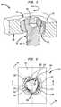
- FIG. 1is a perspective cross-sectional view of a fixation system in accordance with an embodiment
- FIG. 2is a plan view of a section of a plate and an insert of the fixation system of FIG. 1 ;
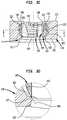
- FIG. 3Ais an elevation view of a cross-section taken at 3 A- 3 A of a portion of the plate and the insert of FIG. 2 ;
- FIG. 3Bis an exploded view taken at region X of FIG. 3A ;
- FIG. 3Cis an elevation view of a cross-section taken at 3 C- 3 C of a portion of the plate and the insert of FIG. 2 ;
- FIG. 3Dis an exploded view taken at region Y of FIG. 3C ;
- FIG. 4is a plan view of a cross-section taken at 4 - 4 of FIG. 3A ;
- FIG. 5is an elevation cross-sectional view of portions of a plate and an insert in accordance with another embodiment.
- FIG. 6is an elevation cross-sectional view of portions of a plate and an insert in accordance with another embodiment.
- fixation system 100generally includes plate 110 , insert 140 , and fastener 95 .
- Plate 110may be but is not limited to being a bone fixation plate, such as may be used for the treatment of proximal humeral, radial, elbow, or clavicle fractures.
- Plate 110may be but is not limited to being made of biocompatible materials such as titanium and its alloys, cobalt and its alloys including cobalt-chromium, and stainless steel.
- Insert 140may be dimensioned and may be flexible such that the insert may be received for polyaxial movement within and frictional locking with aperture 112 of plate 110 .
- Insert 140may be but is not limited to being made of biocompatible materials such as titanium and its alloys, cobalt and its alloys including cobalt-chromium, and stainless steel.
- Fastener 95may be a locking screw having a fully threaded shank 96 , which may be received into a patient's bone or other tissue, as well as threaded head 97 which may include bore 98 for receipt of a turning tool such as a hex-head or TORX screwdriver. As shown, head 97 of fastener 95 may be tapered such that a perimeter of the head adjacent shank 96 may be smaller than a perimeter of the head surrounding bore 98 .
- plate aperture 112 of plate 110may pass through a thickness of plate 110 and may be generally in a square form with the exception of two grooves 113 A, 113 B at opposing corners at a top end of the aperture.
- Upper chamfer 114may extend around plate aperture 112 and between the plate aperture and top surface 115 of plate 110 . Grooves 113 A, 113 B and upper chamfer 114 ease the assembly of insert 140 into plate 110 .
- plate aperture 112may include inner wall 120 as well as opposing upper and lower plate end surfaces 122 , 123 intersecting and extending transversely to opposing ends of inner wall 120 to provide opposing abutments.
- inner wall 120which may have a substantially smooth surface, may extend along a majority of plate aperture 112 .
- Inner wall 120may have a cross-section defined by any given plane through a longitudinal axis of aperture 112 that is substantially in the form of a truncated ellipse.
- Plate aperture 112may include upper guidance surface 126 intersecting upper plate end surface 122 on one end and chamfer 114 on an opposite end of the upper guidance surface to form an upper bearing surface for insert 140 as well as lower guidance surface 127 intersecting lower plate end surface 123 on one end and lower chamfer 116 , which extends to bottom surface 125 of plate 110 , on an opposite end to form a lower bearing surface for insert 140 .
- insert 140may include a body or inner body 142 and collar 162 .
- Inner body 142may include inner surface 144 and outer surface 146 separated by a thickness of the inner body.
- Inner and outer surfaces 144 , 146 of insert 140may extend between top surface 148 and bottom surface 149 of the inner body.
- outer surface 146may be substantially smooth and generally may be in the form of a truncated hollow ellipsoid such that cross-sections of the outer surface taken through the longitudinal axis of aperture 112 define truncated ellipses.
- outer surface 146is in the form of a truncated hollow sphere.
- Inner surface 144may include threads 145 extending along a majority of the length of the inner surface. Inner surface 144 may be tapered such that a portion of the inner surface intersecting top surface 148 may have a larger perimeter than a portion of the inner surface intersecting bottom surface 149 . In this manner, inner surface 144 may be threadably engaged with head 97 of fastener 95 .
- inner surface 144may include first and second recesses 151 , 152 situated generally opposite a slot defined by opposing insert ends 153 , 154 and extending through the thickness of inner body 142 in which first recess 151 is closer to the slot.
- insert 140may be compressed from a rest condition in which the slot and the insert have preset rest widths to a compressed condition in which the slot and the insert have widths smaller than their respective preset rest widths.
- opposing insert ends 153 , 154 of insert 140may be aligned such that when insert 140 is compressed sufficiently, opposing insert ends 153 , 154 may abut each other.
- inner body 142may include notches 156 , 157 adjacent to insert ends 153 , 154 .
- Notches 156 , 157may be dimensioned to receive tines of tongs, a snap ring insertion tool, or other suitable instrument which may be used to urge insert ends 153 , 154 toward each other to reduce the width of insert 140 for placement into plate aperture 112 of plate 110 .
- collar 162extends along the entire perimeter of outer surface 146 of inner body 142 and covers a generally central portion of the outer surface of the inner body.
- a section of collar 162 adjacent to the slot defined by insert ends 153 , 154may be generally the shortest distance from a longitudinal axis through a centroid of the insert relative to the rest of the collar.
- plate aperture 112 and plate grooves 113 A, 113 Bmay be dimensioned such that collar 162 and thus insert 140 must be oriented such that the slot defined by insert ends 153 , 154 is within a region of plate 110 between plate grooves 113 A, 113 B during insertion of the insert into the plate.
- the insertmay be removed only when the insert is oriented about the longitudinal axis of aperture 112 in which the slot defined by insert ends 153 , 154 is situated between plate grooves 113 A, 113 B.
- collar 162includes opposing upper stopper surface 163 and lower stopper surface 164 .
- Upper and lower stopper surfaces 163 , 164extend from inner body 142 such that, during rotation of insert 140 within a plane passing through the longitudinal axis of plate aperture 112 , i.e., during vertical rotation of the insert, when the insert is within the plate, the upper and lower stopper surfaces may abut either or both of corresponding upper and lower plate end surfaces 122 , 123 . In this manner, upper and lower plate end surfaces 122 , 123 restrict vertical rotation of the insert within the plate and aid in preventing disassembly of the insert from the plate.
- insert 140may be moveable in a vertical direction along the longitudinal axis of plate aperture 112 when upper and lower stopper surfaces 163 , 164 are between upper and lower plate end surfaces 122 , 123 .
- Upper and lower plate end surfaces 122 , 123are located along plate aperture 112 such that insert 140 may be rotatable up to 15 degrees in clockwise and counterclockwise directions in which maximum travel is possible when collar 162 is centered in the vertical direction along inner wall 120 of plate 110 .
- Upper and lower stopper surfaces 163 , 164may intersect to define edge 165 .
- edge 165may be in contact with inner wall 120 in the cross-section shown in FIG. 3A and may be in contact with only one side of the inner wall in the cross-section shown in FIG. 3C .
- radii defining the cross-section of outer surface 146 of inner body 142 shown in FIG. 3Amay be different than radii defining the cross-section of inner wall 120 such that the cross-section of outer surface 146 shown curves away from the cross-section of inner wall 120 shown and inwardly towards the longitudinal axis of aperture 112 of plate 110 .
- 3Aare further from inner wall 120 than portions of outer surface 146 further away from the top and bottom surfaces of the inner body in the cross-section shown in FIG. 3A .
- radii defining the cross-section of outer surface 146 of inner body 142 shown in FIG. 3Cmay be different than radii defining the cross-section of inner wall 120 such that the cross-section of outer surface 146 shown curves only slightly inwardly towards the longitudinal axis of aperture 112 of plate 110 .
- portions of outer surface 146 nearest top and bottom surfaces 148 , 149 of inner body 142 in the cross-section shown in FIG. 3Care further from inner wall 120 than portions of outer surface 146 further away from the top and bottom surfaces of the inner body in the cross-section shown in FIG. 3C .
- the cross-section of outer surface 146 shown in FIG. 3C near the intersections of the outer surface with each of top and bottom surfaces 148 , 149may abut the respective upper and lower guidance surfaces 126 , 127 of plate aperture 112 of plate 110 on the side opposite where edge 165 of the insert contacts inner wall 120 in the cross-section shown in FIG. 3C .
- the cross-section of outer surface 146 shown in FIG. 3C near the intersection of the outer surface with the top surface 148may abut the upper guidance surface 126 of aperture 112 of plate 110 on the same side that edge 165 of the insert contacts inner wall 120 in the cross-section shown in FIG. 3C .
- contact between upper and lower guidance surfaces 126 , 127 of plate aperture 112 of plate 110 and outer surface 146 of insert 140may be substantially a point contact.
- contact between inner wall 120 and edge 165 of collar 162 of insert 140may be substantially a point or line contact. In this manner, friction between plate 110 and insert 140 may be minimized during rotation of the insert about the longitudinal axis of plate aperture 112 of the plate and during rotation of the insert within planes passing through the longitudinal axis of aperture 112 .
- inner wall 120 of the plate aperturemay be in the form of a square having rounded corners 128 .
- the insertmay be substantially in the form of a square having collar sections 166 in the form of rounded corners defined by edge 165 of collar 162 in which the rounded corners of the insert generally correspond to the rounded corners of the plate when the insert is placed into the plate.
- one of collar sections 166 of collar 162may be divided by the slot defined by insert ends 153 , 154 .
- Each of collar sections 166may be separated by recesses 167 of collar 162 which, when insert 140 is fully inserted into plate 110 , do not contact aperture 112 of the plate. In this manner, when fastener 95 is inserted, such as by threading, into insert 140 , the interface of collar sections 166 of the insert with respective rounded corners 128 may provide fixation of the insert to the plate and thus fixation of the fastener relative to the plate. Collar recesses 167 may also provide for greater flexibility of insert 140 due to the decrease in thickness of the insert at the locations of these recesses.
- Each of collar sections 166 of collar 162 of insert 140may include a plurality of collar segments, such as first collar segment 168 A, second collar segment 168 B having an end intersecting an end of the first collar segment, and third collar segment 168 C intersecting an end of the second collar segment opposite the end of the second collar segment 168 B intersecting the first collar segment. As demonstrated in the example shown in FIG.
- the points along the length of first collar segment 168 Amay be set at a distance from a longitudinal axis of insert 140 that is less than the distance that the points along the length of collar segment 168 B are set at a distance from the longitudinal axis of the insert, and the points along the length of collar segment 168 B may be set at a distance from the longitudinal axis of the insert that is less than the distance that the points along the length of collar segment 168 C are set at a distance from the longitudinal axis of the insert.
- collar 162 of insert 140may be made of a material that is as hard or harder than the material of aperture 112 of plate 110 such that the collar does not deform upon locking within the plate aperture. In arrangements in which aperture 112 of plate 110 has a similar hardness collar 162 of insert 140 , plate aperture 112 also may not deform during vertical movement of collar 162 along the plate aperture.
- collar 162 of insert 140may be made of a harder material than aperture 112 of plate 110 such that the collar may carve or otherwise deform the plate to create rigid fixation between the insert and the plate.
- the section of collar 162 adjacent to the slot defined by insert ends 153 , 154may be generally the shortest distance from the longitudinal axis through the centroid of the insert relative to the rest of the collar.
- head 97 of fastener 95may be locked with insert 140 at the same time the insert is locked with plate aperture 112 , or as in the example shown, continued rotation of the fastener may lock the fastener head.
- head 97 of fastener 95may be inserted into inner surface 144 of insert 140
- shank 96 of fastener 95may be inserted into a bone, at a predetermined angle relative to the longitudinal axis of aperture 112 of plate 110 . In this manner, upon locking of insert 140 within plate aperture 112 and locking of fastener 95 with inner surface 144 of the insert, the insert and the fastener may be locked at the predetermined angle relative to the longitudinal axis of the plate aperture of plate 110 .
- a physician, or other qualified medical professionalmay determine that a set of bone fragments or bone parts require repair by way of an osteosynthesis or arthrodesis procedure using plate 110 .
- Plate 110may be placed onto each of the bone fragments or bone parts such that at least one plate aperture 112 lies on each of the bone fragments or bone parts.
- Insert 140may be inserted into inner wall 120 of a plate aperture 112 selected by the medical professional.
- the medical professionalmay determine an appropriate insertion angle for insertion of fastener 95 into a bone fragment or bone part to achieve sufficient, and preferably optimal, postoperative stresses.
- Shank 96 of fastener 95may be inserted through inner surface 144 of insert 140 to orient the insert.
- Fastener shank 96then may be threaded, such as by a TORX or a hex head screwdriver, into the bone fragment or bone part at the predetermined insertion angle.
- fastener head 97may be threaded into threads 145 of inner surface 144 of insert 140 causing rotation of the insert within plate 110 until the insert becomes locked within plate aperture 112 .
- fastener 95may be locked with insert 140 and locked relative to plate aperture 112 of plate 110 , at the predetermined angle.
- fastener 95may be unthreaded from the bone fragment or bone part, preferably prior to threading of head 97 with insert 140 , and a new insertion angle for the fastener may be selected. Fastener 95 then may be inserted into the bone fragment or bone part at the newly selected orientation and locked relative to plate 110 as described previously herein.
- fixation system 200may be the same as fixation system 100 with the exception that fixation system 200 may include plate 210 including plate aperture 212 having inner wall 220 in place of plate aperture 112 and inner wall 120 , respectively, of plate 110 and insert 240 having collar 262 in place of collar 162 of insert 140 .
- Insert 240may be the same as insert 140 with the exception that at least collar 262 of insert 240 , and in some arrangements all of insert 240 , is made of a softer material than plate 210 .
- insert 240may be made of but is not limited to being made of any of cobalt-chromium alloys, titanium alloys, steel and its alloys, medical grade polymers, and ceramic when plate 210 is made of a relatively harder material. As such, vertical movement of collar 262 against inner wall 220 deforms the inner wall. In this manner, insert 240 is maintained in plate aperture 212 by both the deformed surface of inner wall 220 and the compression of the insert against the inner wall upon receipt of a fastener into the insert.
- fixation system 300may be the same as fixation system 100 with the exception that fixation system 300 may include insert 340 having collar 362 in place of collar 162 of insert 140 .
- Collar 362may be the same as collar 162 with the exception that collar 362 may include upper and lower stopper surfaces 363 , 364 in place of upper and lower stopper surfaces 163 , 164 and may include edge surface 365 which intersects upper and lower stopper surfaces 363 , 364 to define edges 358 , 359 .
- edge surface 365may be concave such that upper edge 358 and lower edge 359 contact inner wall 120 of plate 110 during rotation and vertical movement of insert 340 within plate aperture 112 .
- the relative distances of any of the collar segmentsmay be in any mixed order and, in some arrangements, may be the same distance such that there are only two segments in any collar section of an insert.
- the plate aperture and the insertmay be in different corresponding non-circular forms at their central cross-sections along the longitudinal axis, such as but not limited to a triangular or an elliptical form, rather than in the square forms of plate 110 and insert 140 .
Landscapes
- Health & Medical Sciences (AREA)
- Orthopedic Medicine & Surgery (AREA)
- Life Sciences & Earth Sciences (AREA)
- Surgery (AREA)
- Neurology (AREA)
- Heart & Thoracic Surgery (AREA)
- Engineering & Computer Science (AREA)
- Biomedical Technology (AREA)
- Nuclear Medicine, Radiotherapy & Molecular Imaging (AREA)
- Medical Informatics (AREA)
- Molecular Biology (AREA)
- Animal Behavior & Ethology (AREA)
- General Health & Medical Sciences (AREA)
- Public Health (AREA)
- Veterinary Medicine (AREA)
- Surgical Instruments (AREA)
Abstract
Description
Claims (20)
Priority Applications (3)
| Application Number | Priority Date | Filing Date | Title |
|---|---|---|---|
| US16/284,520US10980581B2 (en) | 2016-03-17 | 2019-02-25 | Floating locking insert |
| US17/201,688US12193716B2 (en) | 2016-03-17 | 2021-03-15 | Floating locking insert |
| US18/974,893US20250099146A1 (en) | 2016-03-17 | 2024-12-10 | Floating Locking Insert |
Applications Claiming Priority (2)
| Application Number | Priority Date | Filing Date | Title |
|---|---|---|---|
| US15/073,235US10251685B2 (en) | 2016-03-17 | 2016-03-17 | Floating locking insert |
| US16/284,520US10980581B2 (en) | 2016-03-17 | 2019-02-25 | Floating locking insert |
Related Parent Applications (1)
| Application Number | Title | Priority Date | Filing Date |
|---|---|---|---|
| US15/073,235ContinuationUS10251685B2 (en) | 2016-03-17 | 2016-03-17 | Floating locking insert |
Related Child Applications (1)
| Application Number | Title | Priority Date | Filing Date |
|---|---|---|---|
| US17/201,688ContinuationUS12193716B2 (en) | 2016-03-17 | 2021-03-15 | Floating locking insert |
Publications (2)
| Publication Number | Publication Date |
|---|---|
| US20190183548A1 US20190183548A1 (en) | 2019-06-20 |
| US10980581B2true US10980581B2 (en) | 2021-04-20 |
Family
ID=57944246
Family Applications (4)
| Application Number | Title | Priority Date | Filing Date |
|---|---|---|---|
| US15/073,235Active2037-02-12US10251685B2 (en) | 2016-03-17 | 2016-03-17 | Floating locking insert |
| US16/284,520Active2036-05-22US10980581B2 (en) | 2016-03-17 | 2019-02-25 | Floating locking insert |
| US17/201,688Active2037-01-25US12193716B2 (en) | 2016-03-17 | 2021-03-15 | Floating locking insert |
| US18/974,893PendingUS20250099146A1 (en) | 2016-03-17 | 2024-12-10 | Floating Locking Insert |
Family Applications Before (1)
| Application Number | Title | Priority Date | Filing Date |
|---|---|---|---|
| US15/073,235Active2037-02-12US10251685B2 (en) | 2016-03-17 | 2016-03-17 | Floating locking insert |
Family Applications After (2)
| Application Number | Title | Priority Date | Filing Date |
|---|---|---|---|
| US17/201,688Active2037-01-25US12193716B2 (en) | 2016-03-17 | 2021-03-15 | Floating locking insert |
| US18/974,893PendingUS20250099146A1 (en) | 2016-03-17 | 2024-12-10 | Floating Locking Insert |
Country Status (2)
| Country | Link |
|---|---|
| US (4) | US10251685B2 (en) |
| EP (1) | EP3219269B1 (en) |
Families Citing this family (4)
| Publication number | Priority date | Publication date | Assignee | Title |
|---|---|---|---|---|
| US10786289B2 (en)* | 2014-07-16 | 2020-09-29 | The Regents Of The University Of Colorado A Body Corporate | System and methods for positioning of two or more interacting elements |
| EP3629960B1 (en) | 2017-05-22 | 2024-10-09 | McGinley Engineered Solutions, LLC | Variable angle orthopedic fasteners for fixation of an orthopedic implant |
| US10743922B1 (en) | 2019-09-27 | 2020-08-18 | Trilliant Surgical Llc | Variable angle locking construct for orthopedic applications |
| USD949341S1 (en) | 2020-09-29 | 2022-04-19 | Trilliant Surgical Llc | Bone fixation plate |
Citations (114)
| Publication number | Priority date | Publication date | Assignee | Title |
|---|---|---|---|---|
| WO1982001645A1 (en) | 1980-11-14 | 1982-05-27 | Rahmanzadeh Rahim | Device for holding the parts of the joint of a human shoulder |
| US4388921A (en) | 1980-05-28 | 1983-06-21 | Institut Straumann Ag | Device comprising a plate and screws for fastening a plate to a bone |
| SU1130332A1 (en) | 1983-01-26 | 1984-12-23 | Киевский Медицинский Институт Им.Акад.А.А.Богомольца | Apparatus for compression osteosynthesis |
| SU1223901A1 (en) | 1983-10-19 | 1986-04-15 | Новокузнецкий Государственный Ордена Трудового Красного Знамени Институт Усовершенствования Врачей | Apparatus for osteosynthesis |
| US4973332A (en) | 1988-09-12 | 1990-11-27 | Hospital For Joint Diseases | Attachment for femur sliding screw plate |
| US5015248A (en) | 1990-06-11 | 1991-05-14 | New York Society For The Relief Of The Ruptured & Crippled, Maintaining The Hospital For Special Surgery | Bone fracture fixation device |
| US5053036A (en) | 1987-11-03 | 1991-10-01 | Synthes (U.S.A.) | Point contact bone compression plate |
| US5066296A (en) | 1989-02-02 | 1991-11-19 | Pfizer Hopsital Products Group, Inc. | Apparatus for treating a fracture |
| FR2674118A1 (en) | 1991-03-19 | 1992-09-25 | Benoit Girard Cie Sa | Device for spinal osteosynthesis |
| US5151103A (en) | 1987-11-03 | 1992-09-29 | Synthes (U.S.A.) | Point contact bone compression plate |
| DE9308944U1 (en) | 1993-06-16 | 1993-08-12 | Eska Medical GmbH & Co, 23556 Lübeck | Fixation hook |
| WO1994007040A1 (en) | 1992-09-18 | 1994-03-31 | Kuehl Hans | Device for joining at least two elements |
| US5486176A (en) | 1991-03-27 | 1996-01-23 | Smith & Nephew Richards, Inc. | Angled bone fixation apparatus |
| US5531554A (en) | 1993-11-05 | 1996-07-02 | Jbs S.A. | Self-retaining means for fasteners particularly screws |
| US5531745A (en) | 1993-03-11 | 1996-07-02 | Danek Medical, Inc. | System for stabilizing the spine and reducing spondylolisthesis |
| FR2739151A1 (en) | 1995-09-22 | 1997-03-28 | Numedic | Fixing screw for bone implants |
| FR2744011A1 (en) | 1996-01-25 | 1997-08-01 | Richard Rossin | Spinal osteosynthesis device |
| US5681313A (en) | 1995-02-06 | 1997-10-28 | Karl Leibinger Medizintechnik Gmbh & Co. Kg | Device for the extension of bones |
| WO1999009903A1 (en) | 1997-08-27 | 1999-03-04 | Synthes Ag Chur | Locking ring with bayonet for plate osteosynthesis |
| US5951558A (en) | 1998-04-22 | 1999-09-14 | Fiz; Daniel | Bone fixation device |
| US5954722A (en) | 1997-07-29 | 1999-09-21 | Depuy Acromed, Inc. | Polyaxial locking plate |
| US5976141A (en) | 1995-02-23 | 1999-11-02 | Synthes (U.S.A.) | Threaded insert for bone plate screw hole |
| US6017345A (en) | 1997-05-09 | 2000-01-25 | Spinal Innovations, L.L.C. | Spinal fixation plate |
| FR2790198A1 (en) | 1999-02-26 | 2000-09-01 | Numedic | Osteosynthesis plate anchor for bone has sleeve fitting around screw thread to adjustably fit in opening in plate |
| US6129728A (en) | 1998-02-18 | 2000-10-10 | Walter Lorenz Surgical, Inc. | Method and apparatus for mandibular osteosynthesis |
| FR2792185A1 (en) | 1999-04-19 | 2000-10-20 | Numedic | Bone fixation plate fixing screw has rounded head on screw and rounded recess in bone fixing plate to accommodate angular fixing of screw |
| US6193721B1 (en) | 1997-02-11 | 2001-02-27 | Gary K. Michelson | Multi-lock anterior cervical plating system |
| USD440311S1 (en) | 1997-02-11 | 2001-04-10 | Gary K. Michelson | Anterior cervical plate |
| US6221073B1 (en) | 1999-08-20 | 2001-04-24 | Kinetikos Medical, Inc. | Wrist fusion apparatus and method |
| US6235033B1 (en) | 2000-04-19 | 2001-05-22 | Synthes (Usa) | Bone fixation assembly |
| US6235003B1 (en) | 1999-10-12 | 2001-05-22 | Edward D. Dysarz | Inclined plane latching device for a spring needle cannula and a spring needle |
| US6258089B1 (en) | 1998-05-19 | 2001-07-10 | Alphatec Manufacturing, Inc. | Anterior cervical plate and fixation system |
| DE10039767A1 (en) | 2000-01-20 | 2001-07-26 | Impag Gmbh Medizintechnik | Fastening system for mounting shelf on support comprises sleeve around head of screw, outer surfaces of sleeve and bore in component being shaped like part of surface of and screw being inserted at angle and then tipped to compress sleeve |
| US6331179B1 (en) | 2000-01-06 | 2001-12-18 | Spinal Concepts, Inc. | System and method for stabilizing the human spine with a bone plate |
| US20020058939A1 (en) | 1997-08-04 | 2002-05-16 | Spinal Concepts, Inc. | System and method for stabilizing the human spine with a bone plate |
| US6503250B2 (en) | 2000-11-28 | 2003-01-07 | Kamaljit S. Paul | Bone support assembly |
| US6520965B2 (en) | 2001-05-23 | 2003-02-18 | Alan Chervitz | Apparatus and method for orthopedic fixation |
| US6533786B1 (en) | 1999-10-13 | 2003-03-18 | Sdgi Holdings, Inc. | Anterior cervical plating system |
| US6533789B1 (en) | 2000-04-04 | 2003-03-18 | Synthes (Usa) | Device for rotational stabilization of bone segments |
| US6572622B1 (en) | 1999-10-18 | 2003-06-03 | Bernd Schäfer | Bone plate |
| US6602256B1 (en) | 1999-10-11 | 2003-08-05 | Cross Medical Products, Inc. | Bone stabilization plate with a secured-locking mechanism for cervical fixation |
| US20030187440A1 (en) | 2002-03-12 | 2003-10-02 | Marc Richelsoph | Bone plate and screw retaining mechanism |
| US6645209B2 (en) | 2000-04-04 | 2003-11-11 | Synthes (Usa) | Device for rotational stabilization of bone segments |
| US6652525B1 (en) | 1998-04-30 | 2003-11-25 | Sofamor S.N.C. | Anterior implant for the spine |
| US6652530B2 (en) | 2001-09-19 | 2003-11-25 | The University Of Hong Kong | Fixation device |
| US6663632B1 (en) | 1998-05-19 | 2003-12-16 | Synthes (U.S.A.) | Osteosynthetic implant with an embedded hinge joint |
| US6669700B1 (en) | 1997-05-15 | 2003-12-30 | Sdgi Holdings, Inc. | Anterior cervical plating system |
| US6679883B2 (en) | 2001-10-31 | 2004-01-20 | Ortho Development Corporation | Cervical plate for stabilizing the human spine |
| US20040030339A1 (en) | 2001-04-20 | 2004-02-12 | Wack Michael A. | Dual locking plate and associated method |
| FR2844702A1 (en) | 2002-09-24 | 2004-03-26 | Numedic | Device for fixing synthetic bone plate on bone comprises threaded rod passing through non-circular hole housing plate collar to be screwed into bone, constricted collar having non-circular external profile engaging hole |
| US6730091B1 (en) | 1999-05-03 | 2004-05-04 | Medartis Ag | Blockable bone plate |
| US20040102776A1 (en) | 2002-11-19 | 2004-05-27 | Huebner Randall J. | Bone plates with reference marks |
| US6755831B2 (en) | 2001-11-30 | 2004-06-29 | Regents Of The University Of Minnesota | Wrist surgery devices and techniques |
| US20040127896A1 (en) | 2002-10-28 | 2004-07-01 | Alan Lombardo | Bone plate assembly provided with screw locking mechanisms |
| US20040254579A1 (en) | 2003-03-20 | 2004-12-16 | Stryker Trauma S.A. | Bone connection device |
| US20040267261A1 (en) | 2001-11-22 | 2004-12-30 | Guillaume Derouet | Orthopedic implant consisting of a support structure provided with at least an orifice for passing through a fixing screw associated with a nut |
| US20050015131A1 (en)* | 2003-06-16 | 2005-01-20 | Fourcault Eric Stephane | Device destined to be coupled to at least one support, and in particular a surgical implant destined to be coupled to a bone |
| US20050027296A1 (en) | 2002-06-24 | 2005-02-03 | Jeffrey Thramann | Cervical plate with backout protection |
| US20050043736A1 (en) | 2001-12-24 | 2005-02-24 | Claude Mathieu | Device for osteosynthesis |
| US20050049594A1 (en) | 2001-04-20 | 2005-03-03 | Wack Michael A. | Dual locking plate and associated method |
| US6890335B2 (en) | 2001-08-24 | 2005-05-10 | Zimmer Spine, Inc. | Bone fixation device |
| US20050154392A1 (en) | 2004-01-08 | 2005-07-14 | Medoff Robert J. | Fracture fixation system |
| US6929646B2 (en) | 2001-04-04 | 2005-08-16 | Integra Signature Technologies, Inc. | Implantable bone fracture reduction apparatus having a polymeric applicator |
| US20050240187A1 (en) | 2004-04-22 | 2005-10-27 | Huebner Randall J | Expanded fixation of bones |
| US6984234B2 (en) | 2003-04-21 | 2006-01-10 | Rsb Spine Llc | Bone plate stabilization system and method for its use |
| US7001388B2 (en) | 2004-01-23 | 2006-02-21 | Hand Innovations, Llc | System for stabilization of fractures of convex articular bone surfaces including subchondral support structure |
| US20070043366A1 (en) | 2003-04-03 | 2007-02-22 | Medartis Ag | Housing for a locking element and locking element |
| US20070123879A1 (en) | 2003-02-05 | 2007-05-31 | Pioneer Laboratories, Inc. | Bone plate system |
| US7229443B2 (en) | 1998-07-20 | 2007-06-12 | Biedermann Motech Gmbh | Fastening assembly with improved handling properties |
| US7303564B2 (en) | 2002-02-01 | 2007-12-04 | Spinal Concepts, Inc. | Spinal plate extender system and method |
| US20080103501A1 (en) | 2006-08-11 | 2008-05-01 | Ralph Christopher R | Angled Washer Polyaxial Connection for Dynamic Spine Prosthesis |
| US20080306550A1 (en) | 2007-06-07 | 2008-12-11 | Matityahu Amir M | Spine repair assembly |
| US20090076554A1 (en) | 2007-07-19 | 2009-03-19 | Acumed Llc | Insertion tool for bone plates |
| US20090088807A1 (en) | 2007-09-27 | 2009-04-02 | Castaneda Javier E | Locking Screw System With Relatively Hard Spiked Polyaxial Bushing |
| US20090192549A1 (en) | 2008-01-30 | 2009-07-30 | Ebi, Llc | Bone plating system |
| US20090248087A1 (en) | 2008-03-03 | 2009-10-01 | Orthohelix Surgical Designs, Inc. | Variable axis locking mechanism for use in orthopedic implants |
| US20090275987A1 (en) | 2008-05-02 | 2009-11-05 | Thomas James Graham | Bone plate extender and extension system for bone restoration and methods of use thereof |
| US7758620B2 (en) | 2002-09-24 | 2010-07-20 | Stryker Trauma Sa | Device for connecting a screw to a support plate |
| US7771458B2 (en) | 2001-10-23 | 2010-08-10 | Biedermann Motech Gmbh | Bone fixing device |
| US7780710B2 (en) | 2004-01-23 | 2010-08-24 | Depuy Products, Inc. | System for stabilization of fractures of convex articular bone surfaces including subchondral support structure |
| US20100256686A1 (en) | 2009-04-06 | 2010-10-07 | Lanx, Inc. | Bone plate assemblies with backout protection and visual indicator |
| US20100262194A1 (en) | 2007-11-13 | 2010-10-14 | Synthes Gmbh | Periprosthetic Fracture Repair |
| US7833254B2 (en) | 2005-03-11 | 2010-11-16 | Orthofix International B.V. | Device for the ostheosynthesis of proximal humerus fractures |
| US7942913B2 (en) | 2004-04-08 | 2011-05-17 | Ebi, Llc | Bone fixation device |
| US8147530B2 (en) | 2006-03-07 | 2012-04-03 | Orthohelix Surgical Designs, Inc. | Variable axis locking mechanism for use in orthopedic implants |
| US8221421B2 (en) | 2001-02-23 | 2012-07-17 | Synthes Usa, Llc | Sternum fixation device |
| US20120226321A1 (en) | 2011-03-03 | 2012-09-06 | Eduardo Gonzalez-Hernandez | Modular and non-modular cortical buttress device |
| US8287575B2 (en) | 2006-11-09 | 2012-10-16 | Stryker Trauma Gmbh | Polyaxial locking mechanism |
| US20120303071A1 (en) | 2011-05-27 | 2012-11-29 | Michael Black | Securing Fasteners |
| US20130041375A1 (en) | 2011-03-04 | 2013-02-14 | Johann Fierlbeck | Modular Hook Plate Assembly |
| US20130060251A1 (en) | 2011-08-31 | 2013-03-07 | University Of Maryland, Baltimore | Proximal humerus greater tuberosity hook-arm clip |
| US8398636B2 (en) | 2007-04-19 | 2013-03-19 | Stryker Trauma Gmbh | Hip fracture device with barrel and end cap for load control |
| US8444680B2 (en) | 2009-11-09 | 2013-05-21 | Arthrex, Inc. | Polyaxial bushing for locking plate |
| US8486116B2 (en) | 2010-01-08 | 2013-07-16 | Biomet Manufacturing Ring Corporation | Variable angle locking screw |
| US20130211461A1 (en) | 2012-02-13 | 2013-08-15 | Stryker Trauma Sa | Attachment device for a bone plate |
| US8518042B2 (en) | 2010-10-19 | 2013-08-27 | Biomet Manufacturing, Llc | Orthopedic plate assembly for a distal radius having re-contouring features and method for using same |
| US8579898B2 (en) | 2010-03-08 | 2013-11-12 | Memometal Technologies | Adjustable-angle radius plate |
| US8668723B2 (en) | 2011-07-19 | 2014-03-11 | Neurostructures, Inc. | Anterior cervical plate |
| US8728129B2 (en) | 2011-01-07 | 2014-05-20 | Biomet Manufacturing, Llc | Variable angled locking screw |
| US8734494B2 (en) | 2007-04-19 | 2014-05-27 | Stryker Trauma Gmbh | Hip fracture device with static locking mechanism allowing compression |
| US8906070B2 (en) | 2005-10-25 | 2014-12-09 | Robert J. Medoff | Bone fixation device and method |
| US20140367268A1 (en) | 2011-12-07 | 2014-12-18 | C/O Showa Denko K.K. | Jig for manufacturing capacitor element and method for manufacturing capacitor element |
| US8961573B2 (en) | 2010-10-05 | 2015-02-24 | Toby Orthopaedics, Inc. | System and method for facilitating repair and reattachment of comminuted bone portions |
| US8998904B2 (en) | 2012-07-17 | 2015-04-07 | Fastforward Surgical Inc. | Winged tether plate and method of use for reducing angular bone deformity |
| US9084636B2 (en) | 2011-01-10 | 2015-07-21 | Spine Craft, LLC | Surgical plate system and method |
| USD735861S1 (en) | 2014-03-10 | 2015-08-04 | Embark Enterprises Inc. | Quadruped stifle stabilization assembly |
| US9131968B2 (en) | 2013-02-27 | 2015-09-15 | Biomet C.V. | Periprosthetic plating system including plate with system for retaining tension on a cable |
| US9138244B2 (en) | 2013-02-27 | 2015-09-22 | Biomet C.V. | Dynamic compression plate |
| US9138267B2 (en) | 2013-02-27 | 2015-09-22 | Biomet C.V. | Periprosthetic plating system with compressive plate and transverse bridge plate |
| US20150305877A1 (en) | 2014-01-03 | 2015-10-29 | Tornier, Inc. | Reverse shoulder systems and methods |
| US9254154B2 (en) | 2011-03-03 | 2016-02-09 | Toby Orthopaedic, Inc. | Anterior lesser tuberosity fixed angle fixation device and method of use associated therewith |
| US20160038199A1 (en) | 2014-08-08 | 2016-02-11 | Stryker European Holdings I, Llc | Cable plugs for bone plates |
| US9333014B2 (en) | 2013-03-15 | 2016-05-10 | Eduardo Gonzalez-Hernandez | Bone fixation and reduction apparatus and method for fixation and reduction of a distal bone fracture and malunion |
| US9522066B2 (en) | 2011-02-16 | 2016-12-20 | Genesis Medical Devices Llc | Periprosthetic fracture management enhancements |
Family Cites Families (11)
| Publication number | Priority date | Publication date | Assignee | Title |
|---|---|---|---|---|
| US5607428A (en)* | 1995-05-01 | 1997-03-04 | Lin; Kwan C. | Orthopedic fixation device having a double-threaded screw |
| GB2381197A (en)* | 2001-10-25 | 2003-04-30 | Corin Surgical Ltd | A surgical implant |
| DE20321551U1 (en)* | 2003-08-26 | 2007-12-27 | Synthes Gmbh | bone plate |
| US8556944B2 (en)* | 2007-07-31 | 2013-10-15 | Stryker Spine | System and method for vertebral body plating |
| WO2009132302A1 (en)* | 2008-04-25 | 2009-10-29 | Pioneer Surgical Technology, Inc. | Bone plate system |
| JP5759900B2 (en)* | 2008-12-05 | 2015-08-05 | ジンテス ゲゼルシャフト ミット ベシュレンクテル ハフツング | Anchor-in-anchor system for use in bone fixation |
| EP2248479B1 (en)* | 2009-05-06 | 2012-09-19 | Greatbatch Ltd. | Bone plate assembly |
| US20170348030A1 (en)* | 2011-12-09 | 2017-12-07 | Steve L. Haddad | Orthopedic plate, orthopedic device, method of coupling bone segments, and method of assembling an orthopedic plate |
| US9198769B2 (en)* | 2011-12-23 | 2015-12-01 | Pioneer Surgical Technology, Inc. | Bone anchor assembly, bone plate system, and method |
| US20140066998A1 (en)* | 2012-09-06 | 2014-03-06 | Jean-Jacques Martin | Assembly comprising an implantable part designed to be fastened to one or more bones or bone portions to be joined, and at least one screw for fastening the implantable part to said bone(s) |
| US10213237B2 (en)* | 2014-10-03 | 2019-02-26 | Stryker European Holdings I, Llc | Periprosthetic extension plate |
- 2016
- 2016-03-17USUS15/073,235patent/US10251685B2/enactiveActive
- 2017
- 2017-01-27EPEP17000134.1Apatent/EP3219269B1/enactiveActive
- 2019
- 2019-02-25USUS16/284,520patent/US10980581B2/enactiveActive
- 2021
- 2021-03-15USUS17/201,688patent/US12193716B2/enactiveActive
- 2024
- 2024-12-10USUS18/974,893patent/US20250099146A1/enactivePending
Patent Citations (176)
| Publication number | Priority date | Publication date | Assignee | Title |
|---|---|---|---|---|
| US4388921A (en) | 1980-05-28 | 1983-06-21 | Institut Straumann Ag | Device comprising a plate and screws for fastening a plate to a bone |
| WO1982001645A1 (en) | 1980-11-14 | 1982-05-27 | Rahmanzadeh Rahim | Device for holding the parts of the joint of a human shoulder |
| SU1130332A1 (en) | 1983-01-26 | 1984-12-23 | Киевский Медицинский Институт Им.Акад.А.А.Богомольца | Apparatus for compression osteosynthesis |
| SU1223901A1 (en) | 1983-10-19 | 1986-04-15 | Новокузнецкий Государственный Ордена Трудового Красного Знамени Институт Усовершенствования Врачей | Apparatus for osteosynthesis |
| US5151103A (en) | 1987-11-03 | 1992-09-29 | Synthes (U.S.A.) | Point contact bone compression plate |
| US5053036A (en) | 1987-11-03 | 1991-10-01 | Synthes (U.S.A.) | Point contact bone compression plate |
| US4973332A (en) | 1988-09-12 | 1990-11-27 | Hospital For Joint Diseases | Attachment for femur sliding screw plate |
| US5066296A (en) | 1989-02-02 | 1991-11-19 | Pfizer Hopsital Products Group, Inc. | Apparatus for treating a fracture |
| US5015248A (en) | 1990-06-11 | 1991-05-14 | New York Society For The Relief Of The Ruptured & Crippled, Maintaining The Hospital For Special Surgery | Bone fracture fixation device |
| FR2674118A1 (en) | 1991-03-19 | 1992-09-25 | Benoit Girard Cie Sa | Device for spinal osteosynthesis |
| US5486176A (en) | 1991-03-27 | 1996-01-23 | Smith & Nephew Richards, Inc. | Angled bone fixation apparatus |
| WO1994007040A1 (en) | 1992-09-18 | 1994-03-31 | Kuehl Hans | Device for joining at least two elements |
| US5531745A (en) | 1993-03-11 | 1996-07-02 | Danek Medical, Inc. | System for stabilizing the spine and reducing spondylolisthesis |
| DE9308944U1 (en) | 1993-06-16 | 1993-08-12 | Eska Medical GmbH & Co, 23556 Lübeck | Fixation hook |
| US5531554A (en) | 1993-11-05 | 1996-07-02 | Jbs S.A. | Self-retaining means for fasteners particularly screws |
| US5681313A (en) | 1995-02-06 | 1997-10-28 | Karl Leibinger Medizintechnik Gmbh & Co. Kg | Device for the extension of bones |
| US5976141A (en) | 1995-02-23 | 1999-11-02 | Synthes (U.S.A.) | Threaded insert for bone plate screw hole |
| FR2739151A1 (en) | 1995-09-22 | 1997-03-28 | Numedic | Fixing screw for bone implants |
| FR2744011A1 (en) | 1996-01-25 | 1997-08-01 | Richard Rossin | Spinal osteosynthesis device |
| US7074221B2 (en) | 1997-02-11 | 2006-07-11 | Sdgi Holdings, Inc. | Anterior cervical plate system |
| US6527776B1 (en) | 1997-02-11 | 2003-03-04 | Gary K. Michelson | Locking element for locking at least two bone screws to an orthopedic device |
| US6616666B1 (en) | 1997-02-11 | 2003-09-09 | Gary K. Michelson | Apparatus for compressing a spinal disc space disposed between two adjacent vertebral bodies of a cervical spine |
| US6592586B1 (en) | 1997-02-11 | 2003-07-15 | Gary K. Michelson | Single-lock anterior cervical plating system |
| US6712818B1 (en) | 1997-02-11 | 2004-03-30 | Gary K. Michelson | Method for connecting adjacent vertebral bodies of a human spine with a plating system |
| US6969390B2 (en) | 1997-02-11 | 2005-11-29 | Michelson Gary K | Anterior cervical plating system and bone screw |
| US6916320B2 (en) | 1997-02-11 | 2005-07-12 | Gary K. Michelson | Anterior cervical plate system |
| US6193721B1 (en) | 1997-02-11 | 2001-02-27 | Gary K. Michelson | Multi-lock anterior cervical plating system |
| USD440311S1 (en) | 1997-02-11 | 2001-04-10 | Gary K. Michelson | Anterior cervical plate |
| US6926718B1 (en) | 1997-02-11 | 2005-08-09 | Gary K. Michelson | Multilock anterior cervical plating system |
| US20050187552A1 (en) | 1997-02-11 | 2005-08-25 | Michelson Gary K. | Multilock anterior cervical plating system |
| US7137984B2 (en) | 1997-02-11 | 2006-11-21 | Warsaw Orthopedic, Inc. | Single-lock anterior cervical plate and method |
| US6936050B2 (en) | 1997-02-11 | 2005-08-30 | Gary K. Michelson | Multilock anterior cervical plating system |
| US7704255B2 (en) | 1997-02-11 | 2010-04-27 | Warsaw Orthopedic, Inc. | Threadless multi-lock anterior cervical plating system |
| US6936051B2 (en) | 1997-02-11 | 2005-08-30 | Gary K. Michelson | Multilock anterior cervical plating system |
| US6620163B1 (en) | 1997-02-11 | 2003-09-16 | Gary K. Michelson | Anterior cervical plating system and bone screw |
| US7625381B2 (en) | 1997-02-11 | 2009-12-01 | Warsaw Orthopedic, Inc. | System and method for stabilizing a portion of the spine |
| US20130204300A1 (en) | 1997-02-11 | 2013-08-08 | Warsaw Orthopedic, Inc. | Single-lock anterior cervical plate |
| US6398783B1 (en) | 1997-02-11 | 2002-06-04 | Sulzer Spine-Tech Inc. | Multi-lock anterior cervical plate |
| US6416528B1 (en) | 1997-02-11 | 2002-07-09 | Gary K. Michelson | Anterior cervical plating system, instrumentation, and method of installation |
| US6428542B1 (en) | 1997-02-11 | 2002-08-06 | Gary K. Michelson | Single-lock anterior cervical plate |
| US6454771B1 (en) | 1997-02-11 | 2002-09-24 | Gary K. Michelson | Anterior cervical plating system |
| US6273889B1 (en) | 1997-05-09 | 2001-08-14 | Spinal Innovations, Llc | Method of fixing a spine with a fixation plate |
| US6017345A (en) | 1997-05-09 | 2000-01-25 | Spinal Innovations, L.L.C. | Spinal fixation plate |
| US6669700B1 (en) | 1997-05-15 | 2003-12-30 | Sdgi Holdings, Inc. | Anterior cervical plating system |
| US5954722A (en) | 1997-07-29 | 1999-09-21 | Depuy Acromed, Inc. | Polyaxial locking plate |
| US6454769B2 (en) | 1997-08-04 | 2002-09-24 | Spinal Concepts, Inc. | System and method for stabilizing the human spine with a bone plate |
| US20020058939A1 (en) | 1997-08-04 | 2002-05-16 | Spinal Concepts, Inc. | System and method for stabilizing the human spine with a bone plate |
| WO1999009903A1 (en) | 1997-08-27 | 1999-03-04 | Synthes Ag Chur | Locking ring with bayonet for plate osteosynthesis |
| USD449692S1 (en) | 1998-02-11 | 2001-10-23 | Gary K. Michelson | Anterior cervical plate |
| US6129728A (en) | 1998-02-18 | 2000-10-10 | Walter Lorenz Surgical, Inc. | Method and apparatus for mandibular osteosynthesis |
| US5951558A (en) | 1998-04-22 | 1999-09-14 | Fiz; Daniel | Bone fixation device |
| US6652525B1 (en) | 1998-04-30 | 2003-11-25 | Sofamor S.N.C. | Anterior implant for the spine |
| US6626907B2 (en) | 1998-05-19 | 2003-09-30 | Alphatec Manufacturing, Inc. | Anterior cervical plate and fixation system |
| US6258089B1 (en) | 1998-05-19 | 2001-07-10 | Alphatec Manufacturing, Inc. | Anterior cervical plate and fixation system |
| US6663632B1 (en) | 1998-05-19 | 2003-12-16 | Synthes (U.S.A.) | Osteosynthetic implant with an embedded hinge joint |
| US7887569B2 (en) | 1998-05-19 | 2011-02-15 | Synthes Usa, Llc | Osteosynthetic implant with an embedded hinge joint |
| US20110112584A1 (en) | 1998-05-19 | 2011-05-12 | Robert Frigg | Osteosynthetic Implant With An Embedded Hinge Joint |
| US20160310181A1 (en) | 1998-05-19 | 2016-10-27 | DePuy Synthes Products, Inc. | Osteosynthetic Implant With An Embedded Hinge Joint |
| US7229443B2 (en) | 1998-07-20 | 2007-06-12 | Biedermann Motech Gmbh | Fastening assembly with improved handling properties |
| US8388665B2 (en) | 1998-07-20 | 2013-03-05 | Biedermann Technologies Gmbh & Co. Kg | Fastening assembly |
| FR2790198A1 (en) | 1999-02-26 | 2000-09-01 | Numedic | Osteosynthesis plate anchor for bone has sleeve fitting around screw thread to adjustably fit in opening in plate |
| FR2792185A1 (en) | 1999-04-19 | 2000-10-20 | Numedic | Bone fixation plate fixing screw has rounded head on screw and rounded recess in bone fixing plate to accommodate angular fixing of screw |
| US6730091B1 (en) | 1999-05-03 | 2004-05-04 | Medartis Ag | Blockable bone plate |
| US6221073B1 (en) | 1999-08-20 | 2001-04-24 | Kinetikos Medical, Inc. | Wrist fusion apparatus and method |
| US6602256B1 (en) | 1999-10-11 | 2003-08-05 | Cross Medical Products, Inc. | Bone stabilization plate with a secured-locking mechanism for cervical fixation |
| US6235003B1 (en) | 1999-10-12 | 2001-05-22 | Edward D. Dysarz | Inclined plane latching device for a spring needle cannula and a spring needle |
| US6533786B1 (en) | 1999-10-13 | 2003-03-18 | Sdgi Holdings, Inc. | Anterior cervical plating system |
| US6572622B1 (en) | 1999-10-18 | 2003-06-03 | Bernd Schäfer | Bone plate |
| US6331179B1 (en) | 2000-01-06 | 2001-12-18 | Spinal Concepts, Inc. | System and method for stabilizing the human spine with a bone plate |
| DE10039767A1 (en) | 2000-01-20 | 2001-07-26 | Impag Gmbh Medizintechnik | Fastening system for mounting shelf on support comprises sleeve around head of screw, outer surfaces of sleeve and bore in component being shaped like part of surface of and screw being inserted at angle and then tipped to compress sleeve |
| US6533789B1 (en) | 2000-04-04 | 2003-03-18 | Synthes (Usa) | Device for rotational stabilization of bone segments |
| US6645209B2 (en) | 2000-04-04 | 2003-11-11 | Synthes (Usa) | Device for rotational stabilization of bone segments |
| US6235033B1 (en) | 2000-04-19 | 2001-05-22 | Synthes (Usa) | Bone fixation assembly |
| US6575975B2 (en) | 2000-04-19 | 2003-06-10 | Synthes (U.S.A.) | Bone fixation method |
| US6890334B2 (en) | 2000-04-19 | 2005-05-10 | Synthes (U.S.A.) | Bone fixation assembly |
| US6503250B2 (en) | 2000-11-28 | 2003-01-07 | Kamaljit S. Paul | Bone support assembly |
| US8221421B2 (en) | 2001-02-23 | 2012-07-17 | Synthes Usa, Llc | Sternum fixation device |
| US6929646B2 (en) | 2001-04-04 | 2005-08-16 | Integra Signature Technologies, Inc. | Implantable bone fracture reduction apparatus having a polymeric applicator |
| US20040030339A1 (en) | 2001-04-20 | 2004-02-12 | Wack Michael A. | Dual locking plate and associated method |
| US20050049594A1 (en) | 2001-04-20 | 2005-03-03 | Wack Michael A. | Dual locking plate and associated method |
| US6520965B2 (en) | 2001-05-23 | 2003-02-18 | Alan Chervitz | Apparatus and method for orthopedic fixation |
| US6890335B2 (en) | 2001-08-24 | 2005-05-10 | Zimmer Spine, Inc. | Bone fixation device |
| US6652530B2 (en) | 2001-09-19 | 2003-11-25 | The University Of Hong Kong | Fixation device |
| US7771458B2 (en) | 2001-10-23 | 2010-08-10 | Biedermann Motech Gmbh | Bone fixing device |
| US6679883B2 (en) | 2001-10-31 | 2004-01-20 | Ortho Development Corporation | Cervical plate for stabilizing the human spine |
| US20040267261A1 (en) | 2001-11-22 | 2004-12-30 | Guillaume Derouet | Orthopedic implant consisting of a support structure provided with at least an orifice for passing through a fixing screw associated with a nut |
| US6755831B2 (en) | 2001-11-30 | 2004-06-29 | Regents Of The University Of Minnesota | Wrist surgery devices and techniques |
| US8226692B2 (en) | 2001-12-24 | 2012-07-24 | Synthes Usa, Llc | Device for osteosynthesis |
| US7682379B2 (en) | 2001-12-24 | 2010-03-23 | Synthes Usa, Llc | Device for osteosynthesis |
| US7794482B2 (en) | 2001-12-24 | 2010-09-14 | Synthes Usa, Llc | Device for osteosynthesis |
| US8216283B2 (en) | 2001-12-24 | 2012-07-10 | Synthes Usa, Llc | Device for osteosynthesis |
| US8486118B2 (en) | 2001-12-24 | 2013-07-16 | DePuy Synthes Products, LLC | Device for osteosynthesis |
| US20050043736A1 (en) | 2001-12-24 | 2005-02-24 | Claude Mathieu | Device for osteosynthesis |
| US20130274813A1 (en) | 2001-12-24 | 2013-10-17 | DePuy Synthes Products, LLC | Device for osteosynthesis |
| US7303564B2 (en) | 2002-02-01 | 2007-12-04 | Spinal Concepts, Inc. | Spinal plate extender system and method |
| US6695846B2 (en) | 2002-03-12 | 2004-02-24 | Spinal Innovations, Llc | Bone plate and screw retaining mechanism |
| US8500737B2 (en) | 2002-03-12 | 2013-08-06 | Aesculap Implant Systems, Llc | Bone plate and screw retaining mechanism |
| US7972366B2 (en) | 2002-03-12 | 2011-07-05 | Aesculap Implant Systems, Llc | Bone plate and screw retaining mechanism |
| US20040097935A1 (en) | 2002-03-12 | 2004-05-20 | Marc Richelsoph | Bone plate and screw retaining mechanism |
| US20030187440A1 (en) | 2002-03-12 | 2003-10-02 | Marc Richelsoph | Bone plate and screw retaining mechanism |
| US20050027296A1 (en) | 2002-06-24 | 2005-02-03 | Jeffrey Thramann | Cervical plate with backout protection |
| US7175623B2 (en) | 2002-06-24 | 2007-02-13 | Lanx, Llc | Cervical plate with backout protection |
| US9308033B2 (en) | 2002-07-22 | 2016-04-12 | Acumed Llc | Adjustable bone plates |
| US7758620B2 (en) | 2002-09-24 | 2010-07-20 | Stryker Trauma Sa | Device for connecting a screw to a support plate |
| FR2844702A1 (en) | 2002-09-24 | 2004-03-26 | Numedic | Device for fixing synthetic bone plate on bone comprises threaded rod passing through non-circular hole housing plate collar to be screwed into bone, constricted collar having non-circular external profile engaging hole |
| US9241749B2 (en) | 2002-10-28 | 2016-01-26 | Blackstone Medical, Inc. | Bone plate assembly provided with screw locking mechanisms |
| US20040127896A1 (en) | 2002-10-28 | 2004-07-01 | Alan Lombardo | Bone plate assembly provided with screw locking mechanisms |
| US7273481B2 (en) | 2002-10-28 | 2007-09-25 | Blackstone Medical, Inc. | Bone plate assembly provided with screw locking mechanisms |
| US8075602B2 (en) | 2002-10-28 | 2011-12-13 | Blackstone Medical, Inc. | Bone plate assembly provided with screw locking mechanisms |
| US8439957B2 (en) | 2002-10-28 | 2013-05-14 | Blackstone Medical, Inc. | Bone plate assembly provided with screw locking mechanisms |
| US20130345760A1 (en) | 2002-10-28 | 2013-12-26 | Blackstone Medical, Inc. | Bone plate assembly provided with screw locking mechanisms |
| US7704251B2 (en) | 2002-11-19 | 2010-04-27 | Acumed Llc | Adjustable bone plates |
| US7326212B2 (en) | 2002-11-19 | 2008-02-05 | Acumed Llc | Bone plates with reference marks |
| US7090676B2 (en) | 2002-11-19 | 2006-08-15 | Acumed Llc | Adjustable bone plates |
| US20040102776A1 (en) | 2002-11-19 | 2004-05-27 | Huebner Randall J. | Bone plates with reference marks |
| US8172885B2 (en) | 2003-02-05 | 2012-05-08 | Pioneer Surgical Technology, Inc. | Bone plate system |
| US20070123879A1 (en) | 2003-02-05 | 2007-05-31 | Pioneer Laboratories, Inc. | Bone plate system |
| US20040254579A1 (en) | 2003-03-20 | 2004-12-16 | Stryker Trauma S.A. | Bone connection device |
| US9155577B2 (en) | 2003-04-03 | 2015-10-13 | Medartis Ag | Housing for a locking element and locking element |
| US20070043366A1 (en) | 2003-04-03 | 2007-02-22 | Medartis Ag | Housing for a locking element and locking element |
| US6984234B2 (en) | 2003-04-21 | 2006-01-10 | Rsb Spine Llc | Bone plate stabilization system and method for its use |
| US20050015131A1 (en)* | 2003-06-16 | 2005-01-20 | Fourcault Eric Stephane | Device destined to be coupled to at least one support, and in particular a surgical implant destined to be coupled to a bone |
| US20050154392A1 (en) | 2004-01-08 | 2005-07-14 | Medoff Robert J. | Fracture fixation system |
| US7195633B2 (en) | 2004-01-08 | 2007-03-27 | Robert J. Medoff | Fracture fixation system |
| US7780710B2 (en) | 2004-01-23 | 2010-08-24 | Depuy Products, Inc. | System for stabilization of fractures of convex articular bone surfaces including subchondral support structure |
| US7001388B2 (en) | 2004-01-23 | 2006-02-21 | Hand Innovations, Llc | System for stabilization of fractures of convex articular bone surfaces including subchondral support structure |
| US8828064B2 (en) | 2004-04-08 | 2014-09-09 | Ebi, Llc | Bone fixation device |
| US20140228895A1 (en) | 2004-04-08 | 2014-08-14 | Ebi, Llc | Bone fixation device |
| US7942913B2 (en) | 2004-04-08 | 2011-05-17 | Ebi, Llc | Bone fixation device |
| US8177819B2 (en) | 2004-04-22 | 2012-05-15 | Acumed Llc | Expanded fixation of bones |
| US20050240187A1 (en) | 2004-04-22 | 2005-10-27 | Huebner Randall J | Expanded fixation of bones |
| US8337534B2 (en) | 2005-03-11 | 2012-12-25 | Orthofix S.R.L. | Device for the ostheosynthesis of proximal humerus fractures |
| US7833254B2 (en) | 2005-03-11 | 2010-11-16 | Orthofix International B.V. | Device for the ostheosynthesis of proximal humerus fractures |
| US8906070B2 (en) | 2005-10-25 | 2014-12-09 | Robert J. Medoff | Bone fixation device and method |
| US8147530B2 (en) | 2006-03-07 | 2012-04-03 | Orthohelix Surgical Designs, Inc. | Variable axis locking mechanism for use in orthopedic implants |
| US20080103501A1 (en) | 2006-08-11 | 2008-05-01 | Ralph Christopher R | Angled Washer Polyaxial Connection for Dynamic Spine Prosthesis |
| US8287575B2 (en) | 2006-11-09 | 2012-10-16 | Stryker Trauma Gmbh | Polyaxial locking mechanism |
| US20140148861A1 (en) | 2007-04-19 | 2014-05-29 | Stryker Trauma Gmbh | Hip fracture device with static locking mechanism allowing compression |
| US8734494B2 (en) | 2007-04-19 | 2014-05-27 | Stryker Trauma Gmbh | Hip fracture device with static locking mechanism allowing compression |
| US8398636B2 (en) | 2007-04-19 | 2013-03-19 | Stryker Trauma Gmbh | Hip fracture device with barrel and end cap for load control |
| US20080306550A1 (en) | 2007-06-07 | 2008-12-11 | Matityahu Amir M | Spine repair assembly |
| US20090076554A1 (en) | 2007-07-19 | 2009-03-19 | Acumed Llc | Insertion tool for bone plates |
| US20090088807A1 (en) | 2007-09-27 | 2009-04-02 | Castaneda Javier E | Locking Screw System With Relatively Hard Spiked Polyaxial Bushing |
| US20100262194A1 (en) | 2007-11-13 | 2010-10-14 | Synthes Gmbh | Periprosthetic Fracture Repair |
| US20090192549A1 (en) | 2008-01-30 | 2009-07-30 | Ebi, Llc | Bone plating system |
| US20090248087A1 (en) | 2008-03-03 | 2009-10-01 | Orthohelix Surgical Designs, Inc. | Variable axis locking mechanism for use in orthopedic implants |
| US8652179B2 (en) | 2008-05-02 | 2014-02-18 | The Cleveland Clinic Foundation | Bone plate extender and extension system for bone restoration and methods of use thereof |
| US20090275987A1 (en) | 2008-05-02 | 2009-11-05 | Thomas James Graham | Bone plate extender and extension system for bone restoration and methods of use thereof |
| US20100256686A1 (en) | 2009-04-06 | 2010-10-07 | Lanx, Inc. | Bone plate assemblies with backout protection and visual indicator |
| US8444680B2 (en) | 2009-11-09 | 2013-05-21 | Arthrex, Inc. | Polyaxial bushing for locking plate |
| US20130304132A1 (en) | 2010-01-08 | 2013-11-14 | Biomet Manufacturing, Llc | Variable angle locking screw |
| US8486116B2 (en) | 2010-01-08 | 2013-07-16 | Biomet Manufacturing Ring Corporation | Variable angle locking screw |
| US8579898B2 (en) | 2010-03-08 | 2013-11-12 | Memometal Technologies | Adjustable-angle radius plate |
| US8961573B2 (en) | 2010-10-05 | 2015-02-24 | Toby Orthopaedics, Inc. | System and method for facilitating repair and reattachment of comminuted bone portions |
| US8518042B2 (en) | 2010-10-19 | 2013-08-27 | Biomet Manufacturing, Llc | Orthopedic plate assembly for a distal radius having re-contouring features and method for using same |
| US8728129B2 (en) | 2011-01-07 | 2014-05-20 | Biomet Manufacturing, Llc | Variable angled locking screw |
| US20140222084A1 (en) | 2011-01-07 | 2014-08-07 | Biomet Manufacturing, Llc | Variable angled locking screw |
| US9084636B2 (en) | 2011-01-10 | 2015-07-21 | Spine Craft, LLC | Surgical plate system and method |
| US9522066B2 (en) | 2011-02-16 | 2016-12-20 | Genesis Medical Devices Llc | Periprosthetic fracture management enhancements |
| US9254154B2 (en) | 2011-03-03 | 2016-02-09 | Toby Orthopaedic, Inc. | Anterior lesser tuberosity fixed angle fixation device and method of use associated therewith |
| US20120226321A1 (en) | 2011-03-03 | 2012-09-06 | Eduardo Gonzalez-Hernandez | Modular and non-modular cortical buttress device |
| US20130041375A1 (en) | 2011-03-04 | 2013-02-14 | Johann Fierlbeck | Modular Hook Plate Assembly |
| US9072557B2 (en) | 2011-03-04 | 2015-07-07 | DePuy Synthes Products, Inc. | Modular hook plate assembly |
| US20120303071A1 (en) | 2011-05-27 | 2012-11-29 | Michael Black | Securing Fasteners |
| US8668723B2 (en) | 2011-07-19 | 2014-03-11 | Neurostructures, Inc. | Anterior cervical plate |
| US20130060251A1 (en) | 2011-08-31 | 2013-03-07 | University Of Maryland, Baltimore | Proximal humerus greater tuberosity hook-arm clip |
| US20140367268A1 (en) | 2011-12-07 | 2014-12-18 | C/O Showa Denko K.K. | Jig for manufacturing capacitor element and method for manufacturing capacitor element |
| US20130211461A1 (en) | 2012-02-13 | 2013-08-15 | Stryker Trauma Sa | Attachment device for a bone plate |
| US8998904B2 (en) | 2012-07-17 | 2015-04-07 | Fastforward Surgical Inc. | Winged tether plate and method of use for reducing angular bone deformity |
| US9131968B2 (en) | 2013-02-27 | 2015-09-15 | Biomet C.V. | Periprosthetic plating system including plate with system for retaining tension on a cable |
| US9138244B2 (en) | 2013-02-27 | 2015-09-22 | Biomet C.V. | Dynamic compression plate |
| US9138267B2 (en) | 2013-02-27 | 2015-09-22 | Biomet C.V. | Periprosthetic plating system with compressive plate and transverse bridge plate |
| US9333014B2 (en) | 2013-03-15 | 2016-05-10 | Eduardo Gonzalez-Hernandez | Bone fixation and reduction apparatus and method for fixation and reduction of a distal bone fracture and malunion |
| US20150305877A1 (en) | 2014-01-03 | 2015-10-29 | Tornier, Inc. | Reverse shoulder systems and methods |
| USD735861S1 (en) | 2014-03-10 | 2015-08-04 | Embark Enterprises Inc. | Quadruped stifle stabilization assembly |
| US20160038199A1 (en) | 2014-08-08 | 2016-02-11 | Stryker European Holdings I, Llc | Cable plugs for bone plates |
Non-Patent Citations (1)
| Title |
|---|
| Extended European Search Report for Application No. 17000134, dated Aug. 21, 2017. |
Also Published As
| Publication number | Publication date |
|---|---|
| US12193716B2 (en) | 2025-01-14 |
| US20190183548A1 (en) | 2019-06-20 |
| US20210196329A1 (en) | 2021-07-01 |
| US20170265914A1 (en) | 2017-09-21 |
| EP3219269A1 (en) | 2017-09-20 |
| US10251685B2 (en) | 2019-04-09 |
| US20250099146A1 (en) | 2025-03-27 |
| EP3219269B1 (en) | 2019-10-23 |
Similar Documents
| Publication | Publication Date | Title |
|---|---|---|
| US12193716B2 (en) | Floating locking insert | |
| US12295626B2 (en) | Stabilization systems | |
| US10932836B2 (en) | Bone fixation system | |
| US12295627B2 (en) | Stabilization systems | |
| EP3701894A1 (en) | Bone plates and associated screws | |
| US8172885B2 (en) | Bone plate system | |
| US20090192549A1 (en) | Bone plating system | |
| US20110015682A1 (en) | Variable axis locking mechanism for use in orthopedic implants | |
| WO2009042511A1 (en) | Locking screw system with relatively hard spiked polyaxial bushing | |
| US20060235399A1 (en) | Anti-backout mechanism for an implant fastener | |
| US20220257380A1 (en) | Systems and methods for fusion of anatomical joints | |
| EP3001966A1 (en) | Periprosthetic extension plate | |
| US10828076B2 (en) | Bone fixation assembly with enlarged angle of inclination for a bone anchor to a favored side | |
| US20240225705A1 (en) | Systems and methods for bone fixation anchor, plate, and spacer devices | |
| EP3620125A1 (en) | Systems bone fixation anchor, plate, and spacer devices |
Legal Events
| Date | Code | Title | Description |
|---|---|---|---|
| FEPP | Fee payment procedure | Free format text:ENTITY STATUS SET TO UNDISCOUNTED (ORIGINAL EVENT CODE: BIG.); ENTITY STATUS OF PATENT OWNER: LARGE ENTITY | |
| AS | Assignment | Owner name:STRYKER GMBH, SWITZERLAND Free format text:ASSIGNMENT OF ASSIGNORS INTEREST;ASSIGNOR:WIEDERKEHR, ANDREAS;REEL/FRAME:048544/0966 Effective date:20160425 Owner name:STRYKER EUROPEAN HOLDINGS I, LLC, MICHIGAN Free format text:ASSIGNMENT OF ASSIGNORS INTEREST;ASSIGNOR:STRYKER GMBH;REEL/FRAME:048545/0429 Effective date:20160428 | |
| STPP | Information on status: patent application and granting procedure in general | Free format text:DOCKETED NEW CASE - READY FOR EXAMINATION | |
| STPP | Information on status: patent application and granting procedure in general | Free format text:NON FINAL ACTION MAILED | |
| STPP | Information on status: patent application and granting procedure in general | Free format text:NOTICE OF ALLOWANCE MAILED -- APPLICATION RECEIVED IN OFFICE OF PUBLICATIONS | |
| STPP | Information on status: patent application and granting procedure in general | Free format text:PUBLICATIONS -- ISSUE FEE PAYMENT RECEIVED | |
| STPP | Information on status: patent application and granting procedure in general | Free format text:PUBLICATIONS -- ISSUE FEE PAYMENT VERIFIED | |
| STCF | Information on status: patent grant | Free format text:PATENTED CASE | |
| AS | Assignment | Owner name:STRYKER EUROPEAN HOLDINGS III, LLC, DELAWARE Free format text:NUNC PRO TUNC ASSIGNMENT;ASSIGNOR:STRYKER EUROPEAN HOLDINGS I, LLC;REEL/FRAME:056969/0771 Effective date:20210219 Owner name:STRYKER EUROPEAN OPERATIONS HOLDINGS LLC, MICHIGAN Free format text:CHANGE OF NAME;ASSIGNOR:STRYKER EUROPEAN HOLDINGS III, LLC;REEL/FRAME:056969/0893 Effective date:20190226 | |
| MAFP | Maintenance fee payment | Free format text:PAYMENT OF MAINTENANCE FEE, 4TH YEAR, LARGE ENTITY (ORIGINAL EVENT CODE: M1551); ENTITY STATUS OF PATENT OWNER: LARGE ENTITY Year of fee payment:4 | |
| AS | Assignment | Owner name:STRYKER EUROPEAN OPERATIONS HOLDINGS LLC, MICHIGAN Free format text:CHANGE OF ADDRESS;ASSIGNOR:STRYKER EUROPEAN OPERATIONS HOLDINGS LLC;REEL/FRAME:069730/0754 Effective date:20241217 |