US10980403B2 - Endoscopic tool for debriding and removing polyps - Google Patents
Endoscopic tool for debriding and removing polypsDownload PDFInfo
- Publication number
- US10980403B2 US10980403B2US15/804,884US201715804884AUS10980403B2US 10980403 B2US10980403 B2US 10980403B2US 201715804884 AUS201715804884 AUS 201715804884AUS 10980403 B2US10980403 B2US 10980403B2
- Authority
- US
- United States
- Prior art keywords
- tool
- debriding
- endoscope
- endoscopic tool
- conduit
- Prior art date
- Legal status (The legal status is an assumption and is not a legal conclusion. Google has not performed a legal analysis and makes no representation as to the accuracy of the status listed.)
- Active, expires
Links
Images


Classifications
- A—HUMAN NECESSITIES
- A61—MEDICAL OR VETERINARY SCIENCE; HYGIENE
- A61B—DIAGNOSIS; SURGERY; IDENTIFICATION
- A61B17/00—Surgical instruments, devices or methods
- A61B17/32—Surgical cutting instruments
- A61B17/320016—Endoscopic cutting instruments, e.g. arthroscopes, resectoscopes
- A61B17/32002—Endoscopic cutting instruments, e.g. arthroscopes, resectoscopes with continuously rotating, oscillating or reciprocating cutting instruments
- A—HUMAN NECESSITIES
- A61—MEDICAL OR VETERINARY SCIENCE; HYGIENE
- A61B—DIAGNOSIS; SURGERY; IDENTIFICATION
- A61B1/00—Instruments for performing medical examinations of the interior of cavities or tubes of the body by visual or photographical inspection, e.g. endoscopes; Illuminating arrangements therefor
- A61B1/012—Instruments for performing medical examinations of the interior of cavities or tubes of the body by visual or photographical inspection, e.g. endoscopes; Illuminating arrangements therefor characterised by internal passages or accessories therefor
- A61B1/018—Instruments for performing medical examinations of the interior of cavities or tubes of the body by visual or photographical inspection, e.g. endoscopes; Illuminating arrangements therefor characterised by internal passages or accessories therefor for receiving instruments
- A—HUMAN NECESSITIES
- A61—MEDICAL OR VETERINARY SCIENCE; HYGIENE
- A61B—DIAGNOSIS; SURGERY; IDENTIFICATION
- A61B1/00—Instruments for performing medical examinations of the interior of cavities or tubes of the body by visual or photographical inspection, e.g. endoscopes; Illuminating arrangements therefor
- A61B1/31—Instruments for performing medical examinations of the interior of cavities or tubes of the body by visual or photographical inspection, e.g. endoscopes; Illuminating arrangements therefor for the rectum, e.g. proctoscopes, sigmoidoscopes, colonoscopes
- A—HUMAN NECESSITIES
- A61—MEDICAL OR VETERINARY SCIENCE; HYGIENE
- A61B—DIAGNOSIS; SURGERY; IDENTIFICATION
- A61B10/00—Instruments for taking body samples for diagnostic purposes; Other methods or instruments for diagnosis, e.g. for vaccination diagnosis, sex determination or ovulation-period determination; Throat striking implements
- A61B10/02—Instruments for taking cell samples or for biopsy
- A61B10/04—Endoscopic instruments, e.g. catheter-type instruments
- A—HUMAN NECESSITIES
- A61—MEDICAL OR VETERINARY SCIENCE; HYGIENE
- A61B—DIAGNOSIS; SURGERY; IDENTIFICATION
- A61B10/00—Instruments for taking body samples for diagnostic purposes; Other methods or instruments for diagnosis, e.g. for vaccination diagnosis, sex determination or ovulation-period determination; Throat striking implements
- A61B10/02—Instruments for taking cell samples or for biopsy
- A61B2010/0225—Instruments for taking cell samples or for biopsy for taking multiple samples
- A—HUMAN NECESSITIES
- A61—MEDICAL OR VETERINARY SCIENCE; HYGIENE
- A61B—DIAGNOSIS; SURGERY; IDENTIFICATION
- A61B10/00—Instruments for taking body samples for diagnostic purposes; Other methods or instruments for diagnosis, e.g. for vaccination diagnosis, sex determination or ovulation-period determination; Throat striking implements
- A61B10/02—Instruments for taking cell samples or for biopsy
- A61B10/04—Endoscopic instruments, e.g. catheter-type instruments
- A61B2010/045—Needles
- A—HUMAN NECESSITIES
- A61—MEDICAL OR VETERINARY SCIENCE; HYGIENE
- A61B—DIAGNOSIS; SURGERY; IDENTIFICATION
- A61B17/00—Surgical instruments, devices or methods
- A61B2017/00017—Electrical control of surgical instruments
- A—HUMAN NECESSITIES
- A61—MEDICAL OR VETERINARY SCIENCE; HYGIENE
- A61B—DIAGNOSIS; SURGERY; IDENTIFICATION
- A61B17/00—Surgical instruments, devices or methods
- A61B2017/00367—Details of actuation of instruments, e.g. relations between pushing buttons, or the like, and activation of the tool, working tip, or the like
- A61B2017/00398—Details of actuation of instruments, e.g. relations between pushing buttons, or the like, and activation of the tool, working tip, or the like using powered actuators, e.g. stepper motors, solenoids
- A—HUMAN NECESSITIES
- A61—MEDICAL OR VETERINARY SCIENCE; HYGIENE
- A61B—DIAGNOSIS; SURGERY; IDENTIFICATION
- A61B17/00—Surgical instruments, devices or methods
- A61B2017/00535—Surgical instruments, devices or methods pneumatically or hydraulically operated
- A61B2017/00553—Surgical instruments, devices or methods pneumatically or hydraulically operated using a turbine
- A—HUMAN NECESSITIES
- A61—MEDICAL OR VETERINARY SCIENCE; HYGIENE
- A61B—DIAGNOSIS; SURGERY; IDENTIFICATION
- A61B17/00—Surgical instruments, devices or methods
- A61B2017/00743—Type of operation; Specification of treatment sites
- A61B2017/00818—Treatment of the gastro-intestinal system
- A—HUMAN NECESSITIES
- A61—MEDICAL OR VETERINARY SCIENCE; HYGIENE
- A61B—DIAGNOSIS; SURGERY; IDENTIFICATION
- A61B17/00—Surgical instruments, devices or methods
- A61B2017/00831—Material properties
- A61B2017/00862—Material properties elastic or resilient
- A—HUMAN NECESSITIES
- A61—MEDICAL OR VETERINARY SCIENCE; HYGIENE
- A61B—DIAGNOSIS; SURGERY; IDENTIFICATION
- A61B17/00—Surgical instruments, devices or methods
- A61B17/32—Surgical cutting instruments
- A61B17/320016—Endoscopic cutting instruments, e.g. arthroscopes, resectoscopes
- A61B17/32002—Endoscopic cutting instruments, e.g. arthroscopes, resectoscopes with continuously rotating, oscillating or reciprocating cutting instruments
- A61B2017/320032—Details of the rotating or oscillating shaft, e.g. using a flexible shaft
- A—HUMAN NECESSITIES
- A61—MEDICAL OR VETERINARY SCIENCE; HYGIENE
- A61B—DIAGNOSIS; SURGERY; IDENTIFICATION
- A61B2217/00—General characteristics of surgical instruments
- A61B2217/002—Auxiliary appliance
- A61B2217/005—Auxiliary appliance with suction drainage system
- A—HUMAN NECESSITIES
- A61—MEDICAL OR VETERINARY SCIENCE; HYGIENE
- A61B—DIAGNOSIS; SURGERY; IDENTIFICATION
- A61B2217/00—General characteristics of surgical instruments
- A61B2217/002—Auxiliary appliance
- A61B2217/007—Auxiliary appliance with irrigation system
Definitions
- Colon canceris the third leading cause of cancer in the United States but is the second leading cause of cancer-related deaths. Colon cancer arises from pre-existing colon polyps (adenomas) that occur in as many as 35% of the US population. Colon polyps can either be benign, precancerous or cancerous. Colonoscopy is widely regarded as an excellent screening tool for colon cancer that is increasing in incidence worldwide. According to the literature, a 1% increase in colonoscopy screening results in a 3% decrease in the incidence of colon cancer. The current demand for colonoscopy exceeds the ability of the medical system to provide adequate screening. Despite the increase in colon cancer screening the past few decades, only 55% of the eligible population is screened, falling far short of the recommended 80%, leaving 30 million patients at risk.
- colon polypsare removed using a snare that is introduced into the patient's body via a working channel defined within an endoscope.
- the tip of the snareis passed around the stalk of the polyp to cut the polyp from the colon wall. Once the cut has been made, the cut polyp lies on the intestinal wall of the patient until it is retrieved by the operator as a sample.
- the snareis first removed from the endoscope and a biopsy forceps is fed through the same channel of the endoscope to retrieve the sample.
- the limiting factor for patient access to colonoscopyis the amount of time required to complete procedures where patients have colon polyps.
- An improved endoscopic toolis provided that can easily and efficiently obtain samples of multiple polyps from a patient.
- the improved endoscopic toolis capable of debriding one or more polyps and retrieving the debrided polyps without having to alternate between using a separate cutting tool and a separate sample retrieving tool.
- the samplingcan be integrated with colonoscopy inspection.
- an endoscopic biopsy retrieval tooladapted for use with an endoscope a housing, a debriding component coupled to the housing, and a sample retrieval conduit disposed within the housing for retrieving debrided material that is debrided by the debriding component.
- an improved endoscopemay be configured with an integrated endoscopic biopsy retrieval tool that includes a debriding component and a sample retrieval conduit for retrieving debrided material that is debrided by the debriding component.
- a method of retrieving polyps from a patient's bodyincludes disposing an endoscopic tool within an instrumentation channel of an endoscope, inserting the endoscope in a patient's body, actuating a debriding component of the endoscopic tool to cut a polyp within the patient's body, and actuating a sample retrieval component of the endoscopic tool to remove the cut polyp from within the patient's body.
- An endoscopein yet another aspect, includes a first end and a second end separated by a flexible housing.
- An instrumentation channelextends from the first end to the second end and an endoscopic tool is coupled to the instrumentation channel at the first end of the endoscope.
- the endoscopic toolincludes a debriding component and a sample retrieval conduit partially disposed within the instrumentation channel.
- FIG. 1illustrates a perspective partial view of an endoscope according to embodiments of the present disclosure
- FIGS. 2A and 2Billustrate side perspective views of an endoscopic tool coupled with the endoscope shown in FIG. 1 according to embodiments of the present disclosure
- FIGS. 3A and 3Billustrate side perspective views of an alternate endoscopic tool coupled with the endoscope shown in FIG. 1 according to embodiments of the present disclosure
- FIG. 4Aillustrates an exploded view of the endoscopic tool that can be coupled with the endoscope according to embodiments of the present disclosure
- FIG. 4Billustrates a perspective view diagram of the endoscopic tool coupled to the endoscope illustrating the various conduits associated with the endoscopic tool
- FIG. 5illustrates a side perspective view of another alternate endoscopic tool coupled with the endoscope shown in FIG. 1 according to embodiments of the present disclosure
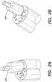
- FIG. 6illustrates an enlarged view of an alternate endoscopic tool according to embodiments of the present disclosure
- FIG. 7illustrates a perspective view of an outer blade of a cutting tool of the endoscopic tool shown in FIG. 6 according to embodiments of the present disclosure
- FIG. 8illustrates a perspective view of an inner blade of the cutting tool of the endoscopic tool shown in FIG. 6 according to embodiments of the present disclosure
- FIG. 9illustrates a perspective view of a rotor of the endoscopic tool shown in FIG. 6 according to embodiments of the present disclosure
- FIG. 10illustrates a perspective view of a casing of the endoscopic tool shown in FIG. 6 according to embodiments of the present disclosure
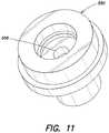
- FIG. 11illustrates a perspective view of a cap of the endoscopic tool shown in FIG. 6 according to embodiments of the present disclosure
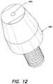
- FIG. 12illustrates a perspective view of a coupling member of the endoscopic tool shown in FIG. 6 according to embodiments of the present disclosure
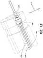
- FIG. 13illustrates a perspective view diagram of the endoscopic tool coupled to the endoscope illustrating the various conduits associated with the endoscopic tool
- FIG. 14illustrates another perspective view diagram of the endoscopic tool coupled to the endoscope illustrating the various conduits associated with the endoscopic tool
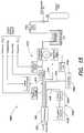
- FIG. 15is a conceptual system architecture diagram illustrating various components for operating the endoscopic tool according to embodiments of the present disclosure.
- the improved endoscopic toolis capable of debriding samples from one or more polyps and retrieving the debrided samples without having to remove the endoscopic tool from the treatment site within the patient's body.
- physicianstypically use a snare device that is capable of cutting polyps grown within the patient's body.
- the snare deviceis not capable of retrieving the cut polyps.
- the physicianin order for a physician to remove polyps from within a patient's body, the physician has to insert the snare device through the working channel of an endoscope, cut the polyps desired to be cut by the physician and leave the cut polyp at or around the surgical site within the patient's body and then remove the snare device from the working channel.
- the physicianthen inserts a sample retrieving device, such as forceps, and removes the cut polyps from the surgical site by grasping the cut polyp and removing the forceps from the working channel of the endoscope and releasing the cut polyp outside the patient's body.
- a sample retrieving devicesuch as forceps
- the physicianmay remove cut polyps one at a time. As one can imagine, this is a very inefficient and time consuming process, while at the same time, may not allow the physician to identify a particular location within the patient's body a particular retrieved polyp had grown. As a result, if any of the retrieved polyps is determined to be cancerous, the physician may not be able to determine the location from which the cancerous polyp was removed hence complicating treatment planning.
- FIG. 1illustrates a perspective partial view of an endoscope according to embodiments of the present disclosure.
- endoscopic toolsadapted for use with any type of endoscope
- teachings of the present disclosureare directed towards endoscopic tools used with a lower GI scope, such as a colonoscope.
- endoscopic tools used with a lower GI scopesuch as a colonoscope.
- the scope of the present disclosureis not limited to endoscopic tools for use with GI scopes, but extends to any type of endoscope, including but not limited to gastroscopes and laryngoscopes, or other medical devices that may be used to treat patients.
- a typical lower GI scope 100includes a flexible body portion that extends from a first end or head portion 102 to a second end or handle portion.
- the head portion 102may be configured to swivel so as to orient a tip 104 of the head portion 102 in any direction within a hemispherical space.
- the handle portion(not shown) has controls that allows the operator of the endoscope 100 to steer the colonoscope towards an area of interest within the colon and turn the corners between colon segments with two steering wheels.
- a series of instrumentsreside on the face 106 of the scope's tip 104 , including but not limited to, one or more water channels 108 A-N, generally referred to as water channels 108 , for irrigating the area with water, one or more light sources 110 A-N, generally referred to as light sources 110 , a camera lens 112 , and an instrument channel 120 through which an endoscopic tool can be passed through to conduct a number of operations.
- the instrumentation channel 120can vary in size based on the type of endoscope 100 being used. In various embodiments, the diameter of the instrumentation channel 120 can range from 3.2 mm to 4 mm.
- Some larger scopesmay have two instrumentation channels 120 so that two tools can be passed into the patient simultaneously. However, larger scopes may cause discomfort to the patient and may be too large to enter the patient's body through some of the smaller cavities.
- FIGS. 2A and 2B and 3A and 3Billustrate side perspective views of an endoscopic tool coupled with the endoscope shown in FIG. 1 according to embodiments of the present disclosure.
- the endoscopic tool 220is configured to be fed through the instrumentation channel 120 of the endoscope 100 .
- the endoscopic tool 220is capable of extending outside the tip 104 of the endoscope 100
- FIGS. 3A and 3Bshow that the endoscope tool 220 can be retracted within the endoscope such that no part of the endoscopic tool 220 is extending beyond the tip 104 of the endoscope 100 .
- the endoscopic tool 220is capable of cutting or debriding a polyp as well as obtaining the debrided polyp from the surgical site without having to remove the endoscopic tool 220 from the endoscope 100 .
- FIG. 4Aillustrates an exploded view of the endoscopic tool 220 adapted for use with the endoscope 100 according to embodiments of the present disclosure.
- the endoscopic tool 220includes a debriding component for debriding polyps grown in the patient's body, and a sample retrieval component for retrieving the debrided polyps from the surgical site.
- the endoscopic toolincludes a tubing 410 coupled to a cap 420 .
- the cap 420may be sealingly engaged with the tubing 410 .
- the capis coupled to a spindle 430 at a first portion of the spindle 430 .
- the spindle 430may be at least substantially hollow.
- the spindle 430is coupled to a rotor 440 , which is configured to rotate the spindle 430 .
- a second portion of the spindle 430includes an inner blade 450 that may be configured to interact with an outer blade 460 .
- the outer blade 460is separated from the inner blade by an irrigation channel (not shown).
- a casing 470is configured to encompass the cap 420 and the rotor 440 , as shown above with respect to FIGS. 2A and 3A . It should be appreciated that other components, such as washers, bearings, seals, and the like, may be included in the endoscopic tool 220 .
- FIG. 4Bis a schematic diagram of a full endoscope including the endoscopic tool or tube tool for insertion into an inspection area via body cavity investigation or endoscopic surgery channel showing good combination of viewing, lighting, the description of distal elements by proximal end adjustment, etc.
- the cap, connector, rotor and casingmay be made from injection molded plastic.
- the spindle and the cannulamay be made from surgical grade steel, and the tubing may be made from silicone.
- these materialsare merely examples of materials that can be used. Those skilled in the art will appreciate that alternate materials may be used instead of the ones described above.
- the tubing 410 in FIG. 4Amay be sized to pass through the instrumentation channel 120 of the endoscope 100 in FIGS. 4A and 4B .
- the tubing 410may include one or more pneumatic fluid entry conduits 412 , one or more pneumatic fluid exit conduits 414 , one or more irrigation conduits 416 , and one or more suction conduits 418 .
- the pneumatic fluid entry conduits 412are configured to supply pressurized air to pneumatically drive the rotor 440 , while the pneumatic fluid exit conduits 414 remove the air supplied by the pneumatic fluid entry conduits 412 to prevent a large amount of air from entering the patient's body.
- the irrigation conduits 416supply an irrigation fluid, such as water, between the inner blade 450 and the outer blade 460 to help lubricate the area between the inner blade 450 and the outer blade 460 .
- the irrigation fluidthen flows from the outside of the inner blade 450 to the inside portion of the inner blade 450 .
- the inside portion of the inner blade 450may be coupled to the suction conduit 418 of the tubing 410 via the cap 420 .
- the irrigation fluid that flows through the inside portion of the inner blade 450 and the suction conduit 418helps lubricate the suction conduit 418 , through which the debrided polyps and other waste from the patient's body are removed.
- the tubing 410is coupled to the cap 420 at a first end, but is coupled to one or more components at a second end (not shown).
- the pneumatic air entry conduits 412may be coupled to a compressed air source
- the irrigation fluid conduit 416may be coupled to a water supply source.
- the pneumatic fluid exit conduits 414may be coupled to the compressed air source or simply left exposed outside the patient's body for venting.
- the suction conduit 418may be coupled to a disposable cartridge that is configured to catch the cut polyps and store them for examination at a later time.
- the disposable cartridgemay include multiple collection bins. The operator may be capable of selecting the collection bin in which to collect a sample of a particular cut polyp. Upon selecting the collection bin, the suction conduit 418 supplies the collected material from within the patient's body to the particular collection bin. As such, the operator may be able to collect samples for each polyp in individual collection bins. In this way, the cancerous nature of individual polyps can be determined.
- the cap 420may be sized to fit within the first end of the tubing 410 .
- the first end of the tubing 410may include a connector that is configured to couple with the cap 420 .
- the cap 420may be press fitted into the connector of the tubing 410 .
- the cap 420may include corresponding conduits that match the conduits of the tubing 410 . Accordingly, compressed air from the compressed air source may be supplied through the pneumatic air entry conduits 412 of the tubing 410 and corresponding pneumatic air entry conduits of the cap 420 towards the rotor 440 .
- the rotor 440may include one or more rotor blades 442 on which the compressed air is impinged thereby causing the rotor 440 to rotate.
- the air impinging on the rotor blades 442may then exit through the corresponding pneumatic air exit conduits of the cap and the pneumatic air entry conduits 414 of the tubing 410 .
- the speed at which the rotor 440 can rotatedepends on the amount of air and the pressure at which the air is supplied to the rotor 440 . In various embodiments, the speed at which the rotor 440 rotates may be controlled by the operator of the endoscope 100 .
- pneumatic means for operating the rotoralternate embodiments may include hydraulic means for operating the rotor. In such embodiments, a fluid, such as water, may be supplied in lieu of compressed air, in the pneumatic air entry conduit 412 .
- the spindle 430is coupled to the rotor 440 , such that when the rotor 440 rotates, the spindle 430 also rotates.
- the first end of the spindle 430includes the inner blade 450 , which correspondingly, also rotates along with the rotor 440 .
- the inner blade 450may be sized to fit within the diameter of the outer blade 460 .
- irrigation fluid supplied from an irrigation fluid sourcemay be supplied through the irrigation fluid conduit 416 of the tubing 410 and the corresponding conduit of the cap 420 , along the space between the inner blade 450 and the outer blade 460 , and into the suction conduit 418 defined by the inner diameter of the inner blade 450 .
- the suction conduit 418is coupled to a vacuum source, fluids and other material may be suctioned through the suction conduit.
- the irrigation fluidis able to lubricate at least a substantial length of the suction conduit 418 , from the tip 452 of the inner blade 450 , through the spindle 430 , cap 420 , and tubing 410 into the disposable cartridge described above.
- the inner blade 450may rotate relative to the outer blade 460 such that the interaction between the inner blade 450 and the outer blade 460 causes polyps to he cut upon contact with the inner blade 450 .
- other mechanisms for cutting polypsmay be utilized, which may or may not include the use of a rotor 440 , inner blade 450 or outer blade 460 .
- the debriding componentmay generally be configured to debride a polyp.
- debridemay be defined herein to refer to any action involving detaching the polyp from a surface of the patient's body. Accordingly, actions, including but not limited to, cutting, snaring, shredding, slicing, shattering, either entirely or partially, are also considered to lie within the definition of the term debride. Accordingly, the debriding component may be a component that is capable of cutting, snaring, shredding, slicing, shattering, a polyp from a surface of the patient's body.
- the debriding componentmay be implemented as a forceps, scissor, knife, snare, shredder, or any other component that can debride a polyp.
- the debriding componentmay be manually actuated such that the debriding component may be operated through the translation of mechanical forces exerted by an operator or automatically actuated, using a turbine, electrical motor, or any other force generating component to actuate the debriding component.
- the debriding componentmay be actuated hydraulically, pneumatically, or electrically.
- a separate conduit passing through the tubing or a channel of the endoscopemay he configured to carry an electrical wire to provide power to the electrically powered actuator, such as an electrical motor.
- the debriding componentmay include a turbine assembly, which is made up of the rotor 440 , the rotor blades 442 , and the spindle 430 .
- the operatormay actuate the debriding component of the endoscopic tool by supplying compressed air to the turbine assembly.
- the operatorWhen the operator is ready to begin debriding the polyp, the operator actuates the turbine assembly causing the debriding component to be actuated.
- actuating the debriding componentmay constitute causing the inner blade 450 to rotate relative to the outer blade 460 .
- the operatormay bring the endoscopic tool 220 towards the polyp to be debrided causing the inner blade 450 to debride the polyp, causing portions of the debrided polyp to lie in the vicinity around the area where the polyp had grown.
- the operatormay then de-actuate the turbine assembly and actuate suction through the suction conduit 418 .
- the operatormay then bring the inner blade close to the cut polyp causing the cut polyp to be retrieved through the suction conduit 418 .
- the suction component of the endoscopic toolmay be actuated while the debriding component is actuated, thereby allowing any debrided material to be retrieved by the suction component.
- the debriding componentmay be manually operated or may utilize any other means of debriding a polyp such that the debrided polyps are capable of being retrieved from the surgical site via the suction conduit described above.
- examples of debriding componentsmay include, but are not limited to, snips, blades, saws, or any other sharp tools that may or may not be driven by a turbine assembly. It should be appreciated that using a debriding component that is able to cut a polyp into small enough pieces may be desirable such that the cut pieces may be retrieved via the suction conduit without having to remove the endoscopic tool from the endoscope.
- the geometry and assembly of the turbine assembly for rotating at least one of the cutting tool bladesmay be based on fluid dynamics. Bernoulli's equation can be used to explain the conversion between fluid pressure and the fluid velocity. According to this equation, the fluid velocity is related to the initial fluid pressure by the equation:
- V2 * P D where V is Velocity, P is Pressure, and D is Mass density.
- the fluidIn order for the fluid to reach the calculated velocity, the fluid can be developed at the point of exit such that the channel through which the fluid is flowing meets an empirically determined L/D ratio of 2, where ‘D’ is the wetted diameter of the flow and the ‘L’ is the length of the channel.
- ⁇ Fd dt ⁇ ( ⁇ ⁇ ⁇ Vp * dVol . ) + ⁇ ( m . ⁇ V ) out - ⁇ ( m . ⁇ V ) i ⁇ ⁇ n
- ⁇ dot over (m) ⁇is the mass flow of the impinging air jet
- Vis Volume
- V out and V inare the same in an impulse turbine, the momentum change being created by the changing direction of the fluid only.
- the mass flow ⁇ dot over (m) ⁇is defined by the pump that is to be specified.
- the actual numerical valuealso needs to account for the velocity of the rotor.
- ⁇ F⁇ dot over (m) ⁇ ( V jet ⁇ V rotor ) ⁇ ( V jet ⁇ V rotor )cos ⁇ )
- ⁇ F⁇ dot over (m) ⁇ ( V jet ⁇ V rotor )(1 ⁇ cos ⁇ ) where ‘ ⁇ ’ is the difference of the angle between the incoming air jet to that of the exiting air jet.
- ⁇ T( ⁇ dot over (m) ⁇ /r )( V jet ⁇ V rotor )(1 ⁇ cos ⁇ )
- a second force that must be consideredcomes from redirecting the air jet from the nozzle into the turbine wheel.
- the air jetmust he turned 90° into the direction of the blades from the direction of the air jet.
- FIG. 4Ba perspective view diagram of the endoscopic tool coupled to the endoscope illustrating the various conduits associated with the endoscopic tool is shown.
- the pneumatic air entry conduit 412is shown supplying pressurized air to the rotor assembly, while the pneumatic air exit conduit 412 (not shown in this view) removes the air from the rotor assembly to outside the endoscope 100 .
- the irrigation channel 416is shown to carry irrigation fluid into the endoscopic tool 220 , where the irrigation fluid enters into the suction conduit 418 , which carries material from within the patient's body to a collection component outside the endoscope. As shown in FIG. 4B , the irrigation fluid may enter the suction conduit 418 at an irrigation fluid entry opening 419 .
- irrigation fluid entry opening 419may be placed anywhere along the suction conduit. Due to the suction force being applied to the suction conduit, irrigation fluid may be forced into the suction conduit without the risk of the materials flowing in the suction conduit from flowing outside the suction conduit through the irrigation fluid entry opening 419 . Moreover, in some embodiments, the irrigation channel may only supply irrigation fluid to the endoscopic tool while suction is being applied to the suction conduit.
- FIG. 5illustrates a side perspective view of another alternate endoscopic tool coupled with the endoscope shown in FIG. 1 according to embodiments of the present disclosure.
- the add-on endoscopic tool 500is sized to couple with the walls defining the instrumentation channel 120 of the tip 104 of the endoscope 100 .
- the add-on endoscopic tool 500may be removably attached to the instrumentation channel 120 of the endoscope 100 at the tip 104 of the endoscope 104 by way of an interference fit or a press fit.
- the add-on endoscopic tool 500may be coupled to the endoscope 100 using other attachment means known to those skilled in the art.
- the add-on endoscopic toolincludes an outer blade or support member 510 , an inner blade 520 disposed within the outer blade 510 , a rotor 530 coupled to the inner blade 520 and encompassed by a casing 540 .
- the casingis coupled to a cap 550 , which is further coupled to a connector 560 .
- the connector 560may be sized to engage with the inner diameter of the instrumentation channel 120 of the endoscope 100 .
- any other component of the endoscopic toolmay be configured to engage with the endoscope 100 in such a manner as to secure the endoscopic tool to the instrumentation channel 120 .
- FIGS. 7-12illustrate perspective views of the individual components of the add-on endoscopic tool shown in FIG. 6 according to embodiments of the present disclosure.
- the add-on endoscopic tool 500may be adapted to fit within a first end of instrumentation channel 120 of the endoscope 100 .
- a second end of the instrumentation channel 120may be coupled to a vacuum source, which causes material to be suctioned through the instrumentation channel 120 .
- a suction conduitextends from the vacuum source through the instrumentation channel of the endoscope, and further through the connector 560 , the cap 550 , and the rotor 530 , to a first end of the inner blade 520 , which has an opening defined by the inner diameter of the inner blade 520 .
- the connector 560 , the cap 550 , the casing 540 , and the rotor 530have respective center bores 566 , 556 , 546 and 536 that are aligned such that materials arc allowed to flow from the opening of the inner blade 520 to the vacuum source via the second end of the instrumentation channel 120 .
- the casing 540 of the add-on endoscopic tool 500includes a pneumatic air entry port 542 and a pneumatic air exit port 544 as shown in FIG. 10 .
- the pneumatic air entry port 542may be adapted to receive compressed air from a compressed air source through a pneumatic air entry conduit that passes along the length of the endoscope 100 to outside the patient's body
- the pneumatic air exit port 544may be adapted to vent air that is impinged on the rotor 530 through a pneumatic air exit conduit that passes along the length of the endoscope 100 to outside the patient's body.
- the rotormay be actuated by supplying compressed air from the compressed air source, as described above with respect to FIGS. 1-4 .
- the rotor and associated components disclosed hereindescribe the use of pneumatic air
- the rotormay he driven hydraulically.
- the pneumatic air conduitsmay be configured to carry a liquid, such as water, to and from the area around the rotor.
- the pneumatic air entry and exit conduitsmay extend from the add-on endoscopic tool to a pneumatic air source through the instrumentation channel 120 of the endoscope 100 .
- a tubing that includes separate conduits for the pneumatic air entry and exit conduits and the suction conduitmay extend from outside the endoscope to the add-on endoscopic tool within the endoscope.
- the tubingmay be capable of being fed through the instrumentation channel of the endoscope and coupled to the add-on endoscopic tool 500 .
- the add-on endoscopic tool 500may be configured with an additional component that has predefined channels that couple the respective channels of the tubing with the associated with the pneumatic air entry and exit openings of the add-on endoscopic tool and the suction conduit formed within the add-on endoscopic tool.
- an irrigation fluid channelmay also be defined within the tubing such that irrigation fluid may be supplied to the add-on endoscopic tool 500 , from where the irrigation fluid is diverted into the suction conduit.
- the tip of the outer blade 510may be sharp and may cause discomfort to the patient while entering a cavity of the patient's body.
- a guard structure(not shown), such as a gel cap or other similar structure, may be attached to the outer blade prior to inserting the add-on endoscopic tool into the patient's body to prevent injuries from the outer blade contacting a surface of the patient's body. Once the endoscopic tool is inserted in the patient's body, the guard structure may be released from the outer blade 510 . In various embodiments, the guard structure may dissolve upon entering the patient's body.
- the improved endoscope 1400may be similar to conventional endoscopes in many aspects, but may differ in that the improved endoscope may include a built in polyp removal assembly 1440 within an instrumentation channel of the endoscope 1400 .
- the polyp removal assembly 1440may include a turbine assembly having a rotor 1442 with rotor blades sealed in a casing 1444 that has one or more inlet and outlet ports for allowing either pneumatic or hydraulic fluid to actuate the rotor 1442 .
- the inlet portsmay be designed such that the fluid may interact with the rotor blades at a suitable angle to ensure that the rotor can be driven at desired speeds.
- the polyp removal assembly 1440may be coupled to a connector 1420 , which is configured to couple the polyp removal assembly 1440 to a tubing 1470 .
- the tubing 1470may include a pneumatic air entry conduit 1412 , a pneumatic air exit conduit (not shown), an irrigation fluid conduit 1416 and a suction conduit 1418 that passes through the center of the turbine assembly.
- the tubing 1440may be sized such that the tubing 1440 can be securely coupled to the connector 1420 such that one or more of the conduits of the tubing 1440 are coupled to corresponding conduits within the connector 1440 .
- the connector 1420may be designed to include an irrigation fluid entry opening 419 , which allows irrigation fluid to pass into the suction conduit 1418 of the tubing 1440 when the tubing is coupled to the connector.
- the turbine assembly of the endoscope 1400may be configured to couple with a removable debriding assembly 1460 , which includes a spindle and a cannula, in a manner that causes the debriding assembly to be operational when the turbine assembly is operating.
- an endoscopemay be designed to facilitate debriding one or more polyps and removing the debrided material associated with the polyps in a single operation.
- the endoscopemay include one or more separate channels for removing debrided material, supplying irrigation fluid, and supplying and removing at least one of pneumatic or hydraulic fluids.
- the endoscopemay include a debriding component that may be fixedly or removably coupled to one end of the endoscope.
- a separate debriding component channelmay also be designed for the debriding component.
- the endoscopemay include a light and a camera.
- the endoscopemay utilize existing channels to supply pneumatic or hydraulic fluids to the actuator of the endoscopic tool for actuating the debriding component.
- the water channels 108 A-Nmay be modified to supply fluids to the actuator pneumatically or hydraulically.
- the endoscopic toolmay include a connector having a first end capable of being coupled to an opening associated with existing channels 108 of the endoscope, while another end of the connector is exposed to an opening at the actuator.
- the endoscopic toolmay further be configured to detect the presence of tissue or muscle. This may be useful for physicians to take extra precautions to prevent bowel perforations while debriding polyps.
- the endoscopic toolmay be equipped with an electrical sensor that can communicate with a sensor processing component outside the endoscope to determine if a particular region of the patient's body is made from tissue or muscle. The sensor may gather temperature information as well as density information and provide signals corresponding to such to the sensor processing unit, which can determine from the signals, if the particular region is made from tissue or muscle.
- the endoscopic toolmay be equipped with an injectable dye component through which a physician may mark a particular region within the patient's body.
- the physicianmay mark a particular region utilizing the debriding component, without the use of an injectable dye.
- an endoscopic toolincluding but not limited to a tool that may be attached to the tip of the endoscope, and a tool that may be fed through the length of the endoscope
- the scope of the present disclosureis not intended to be limited to such embodiments or to endoscopic tools in general. Rather, the scope of the present disclosure extends to any device that may debride and remove polyps from within a patient's body using a single tool.
- the scope of the present disclosureextends to improved endoscopes that may be built with some or all of the components of the endoscopic tools described herein. For instance, an improved endoscope with a built in turbine assembly and configured to be coupled to a debriding component is also disclosed herein.
- the endoscopemay also include predefined conduits that extend through the length of the endoscope such that only the suction conduit may be defined by a disposable tubing, while the air entry and exit conduits and the irrigation conduit are permanently defined within the improved endoscope.
- the suction conduitis also predefined but made such that the suction conduit may be cleaned and purified for use with multiple patients.
- the debriding componentmay also be a part of the endoscope, but also capable of being cleaned and purified for use with multiple patients.
- any or all of the components that constitute the endoscopic toolmay be built into an existing endoscope or into a newly designed endoscope for use in debriding and removing polyps from within the patients body.
- the endoscopic system 1500includes an endoscope 100 fitted with an endoscopic tool 220 , and which may be coupled to an air supply measurement system 1510 , an irrigation system 1530 and a polyp removal system 1540 .
- the tubing that extends within the endoscope 100may include one or more pneumatic air entry conduits 412 and one or more pneumatic air exit conduits 414 .
- the pneumatic air entry conduits 412are coupled to the air supply measurement system 1510 , which includes one or more sensors, gauges, valves, and other components to control the amount of gas, such as air, being supplied to the endoscope 100 to drive the rotor 440 .
- the amount of air being supplied to the rotor 440may be controlled using the air supply measurement system 1510 .
- delivery of the air to actuate the rotor 440may be manually controlled by the physician using the endoscope 100 .
- the physicianmay use a foot pedal or a hand-actuated lever to supply air to the rotor 440 .
- the pneumatic air exit conduit 414may not be coupled to any component. As a result, air exiting from the rotor 440 may simply exit the endoscope via the pneumatic air exit conduit 414 into the atmosphere. In alternate embodiments, the pneumatic air exit conduit 414 may be coupled to the air supply measurement system 1510 such that the air exiting the pneumatic air exit conduit 414 is supplied back to the rotor via the pneumatic air entry conduit 412 . It should be appreciated that a similar setup may be used for a hydraulically driven turbine system.
- the endoscope 100may also be coupled to the irrigation system 1530 via the irrigation fluid conduit 416 .
- the irrigation system 1530may include a flow meter 1534 coupled to an irrigation source 1532 for controlling the amount of fluid flowing from the irrigation source 1532 to the endoscope 100 .
- the endoscope 100may also include a suction conduit 418 for removing polyps from within the patient's body.
- the suction conduit 418may be coupled to the polyp removal system 1540 , which may be configured to store the polyps.
- the physicianmay be able to collect samples in one or more cartridges 1542 within the polyp removal system 1540 such that the removed polyps can be tested individually.
- an endoscopecomprises a first end and a second end separated by a flexible housing, an instrumentation channel extending from the first end to the second end, and an endoscopic tool comprising a debriding component and a sample retrieval conduit disposed within the instrumentation channel.
- the endoscopic toolmay further include a flexible tubing in which the sample retrieval conduit is partially disposed, the flexible tubing extending from the first end to the second end of the endoscope.
- the flexible tubingmay also include a pneumatic air entry conduit and a fluid irrigation conduit.
- the debriding componentmay include a turbine assembly and a cutting tool.
- the instrumentation channelmay have a diameter that is larger than the instrumentation channels of existing endoscopes. In this way, larger portions of debrided material may be suctioned from within the patient's body without clogging the suction conduit.
- an endoscopemay include a first end and a second end separated by a flexible housing; an instrumentation channel extending from the first end to the second end; and an endoscopic tool coupled to the instrumentation channel at the first end of the endoscope, the endoscopic tool comprising a debriding component and a sample retrieval conduit partially disposed within the instrumentation channel.
- the endoscopic toolmay be removably attached to the endoscopic tool.
- an endoscopic systemin other embodiments of the present disclosure, includes an endoscope comprising a first end and a second end separated by a flexible housing and an instrumentation channel extending from the first end to the second end and an endoscopic tool coupled to the instrumentation channel at the first end of the endoscope.
- the endoscopic toolmay include a debriding component and a flexible tubing having a length that is greater than the length of the endoscope.
- the flexible tubingmay include a sample retrieval conduit, an pneumatic air entry conduit, and a fluid irrigation conduit, a disposable cartridge configured to couple with the sample retrieval conduit proximal the second end of the endoscope, a pressurized air source configured to couple with the pneumatic air entry conduit proximal the second end of the endoscope, and a fluid irrigation source configured to couple with the fluid irrigation conduit proximal the second end of the endoscope.
- the endoscopemay also include at least one camera source and at least one light source.
- the pneumatic air entry conduitsupplies pressurized air to a turbine assembly of the debriding component proximal the first end of the endoscope and the fluid irrigation conduit supplies irrigation fluid to the sample retrieval conduit proximal the first end of the endoscope.
Landscapes
- Health & Medical Sciences (AREA)
- Life Sciences & Earth Sciences (AREA)
- Surgery (AREA)
- General Health & Medical Sciences (AREA)
- Public Health (AREA)
- Veterinary Medicine (AREA)
- Nuclear Medicine, Radiotherapy & Molecular Imaging (AREA)
- Animal Behavior & Ethology (AREA)
- Molecular Biology (AREA)
- Engineering & Computer Science (AREA)
- Biomedical Technology (AREA)
- Heart & Thoracic Surgery (AREA)
- Medical Informatics (AREA)
- Radiology & Medical Imaging (AREA)
- Pathology (AREA)
- Biophysics (AREA)
- Physics & Mathematics (AREA)
- Optics & Photonics (AREA)
- Orthopedic Medicine & Surgery (AREA)
- Endoscopes (AREA)
- Surgical Instruments (AREA)
- Instruments For Viewing The Inside Of Hollow Bodies (AREA)
- Sampling And Sample Adjustment (AREA)
Abstract
Description
where V is Velocity, P is Pressure, and D is Mass density.
where: {dot over (m)} is the mass flow of the impinging air jet, and V is Volume.
ΣF={dot over (m)}(Vout−Vin)
ΣF={dot over (m)}(Vjet−Vrotor)−(Vjet−Vrotor)cosθ)
ΣF={dot over (m)}(Vjet−Vrotor)(1−cosθ)
where ‘θ’ is the difference of the angle between the incoming air jet to that of the exiting air jet. Thought theoretically, the maximum amount of torque can be generated by a ‘θ’ value of 180°, but doing so will actually send the incoming jet onto the back of the following blade. Accordingly, the angle is best given a design value 15° to 20° below 180 to allow a fluid a clean exit. Finally, the force can be defined into a rotational torque:
ΣT=({dot over (m)}/r)(Vjet−Vrotor)(1−cosθ)
ΣF={dot over (m)}Vjet
Claims (15)
Priority Applications (3)
| Application Number | Priority Date | Filing Date | Title |
|---|---|---|---|
| US15/804,884US10980403B2 (en) | 2011-12-02 | 2017-11-06 | Endoscopic tool for debriding and removing polyps |
| US17/234,270US11812933B2 (en) | 2011-12-02 | 2021-04-19 | Endoscopic tool for deb riding and removing polyps |
| US18/504,253US12402784B2 (en) | 2011-12-02 | 2023-11-08 | Endoscopic tool for debriding and removing polyps |
Applications Claiming Priority (3)
| Application Number | Priority Date | Filing Date | Title |
|---|---|---|---|
| US201161566472P | 2011-12-02 | 2011-12-02 | |
| US13/336,491US9808146B2 (en) | 2011-12-02 | 2011-12-23 | Endoscopic tool for debriding and removing polyps |
| US15/804,884US10980403B2 (en) | 2011-12-02 | 2017-11-06 | Endoscopic tool for debriding and removing polyps |
Related Parent Applications (2)
| Application Number | Title | Priority Date | Filing Date |
|---|---|---|---|
| US13/336,491ContinuationUS9808146B2 (en) | 2011-12-02 | 2011-12-23 | Endoscopic tool for debriding and removing polyps |
| US13/336,491DivisionUS9808146B2 (en) | 2011-12-02 | 2011-12-23 | Endoscopic tool for debriding and removing polyps |
Related Child Applications (1)
| Application Number | Title | Priority Date | Filing Date |
|---|---|---|---|
| US17/234,270ContinuationUS11812933B2 (en) | 2011-12-02 | 2021-04-19 | Endoscopic tool for deb riding and removing polyps |
Publications (2)
| Publication Number | Publication Date |
|---|---|
| US20180064315A1 US20180064315A1 (en) | 2018-03-08 |
| US10980403B2true US10980403B2 (en) | 2021-04-20 |
Family
ID=48524503
Family Applications (4)
| Application Number | Title | Priority Date | Filing Date |
|---|---|---|---|
| US13/336,491Active2035-02-02US9808146B2 (en) | 2011-12-02 | 2011-12-23 | Endoscopic tool for debriding and removing polyps |
| US15/804,884Active2033-02-23US10980403B2 (en) | 2011-12-02 | 2017-11-06 | Endoscopic tool for debriding and removing polyps |
| US17/234,270Active2032-09-18US11812933B2 (en) | 2011-12-02 | 2021-04-19 | Endoscopic tool for deb riding and removing polyps |
| US18/504,253ActiveUS12402784B2 (en) | 2011-12-02 | 2023-11-08 | Endoscopic tool for debriding and removing polyps |
Family Applications Before (1)
| Application Number | Title | Priority Date | Filing Date |
|---|---|---|---|
| US13/336,491Active2035-02-02US9808146B2 (en) | 2011-12-02 | 2011-12-23 | Endoscopic tool for debriding and removing polyps |
Family Applications After (2)
| Application Number | Title | Priority Date | Filing Date |
|---|---|---|---|
| US17/234,270Active2032-09-18US11812933B2 (en) | 2011-12-02 | 2021-04-19 | Endoscopic tool for deb riding and removing polyps |
| US18/504,253ActiveUS12402784B2 (en) | 2011-12-02 | 2023-11-08 | Endoscopic tool for debriding and removing polyps |
Country Status (7)
| Country | Link |
|---|---|
| US (4) | US9808146B2 (en) |
| EP (2) | EP3305224B1 (en) |
| JP (1) | JP6165764B2 (en) |
| CN (2) | CN104220016B (en) |
| AU (4) | AU2012345609B2 (en) |
| CA (1) | CA2857671C (en) |
| WO (1) | WO2013082602A2 (en) |
Families Citing this family (24)
| Publication number | Priority date | Publication date | Assignee | Title |
|---|---|---|---|---|
| WO2013068017A1 (en) | 2011-11-09 | 2013-05-16 | Tomas Gundberg | Handheld tissue sample extraction device |
| US8882680B2 (en) | 2011-12-02 | 2014-11-11 | Interscope, Inc. | Insertable endoscopic instrument for tissue removal |
| US9808146B2 (en) | 2011-12-02 | 2017-11-07 | Interscope, Inc. | Endoscopic tool for debriding and removing polyps |
| WO2015077584A2 (en)* | 2013-11-22 | 2015-05-28 | Massachusetts Institute Of Technology | Steering techniques for surgical instruments |
| EP3200707A1 (en)* | 2014-09-30 | 2017-08-09 | Interscope Inc. | Endoscope including a torque generation component or torque delivery component disposed within an insertable portion of the endoscope and a surgical cutting assembly insertable within the endoscope |
| DE102015114044A1 (en)* | 2015-08-25 | 2017-03-02 | Acandis Gmbh & Co. Kg | Medical aspiration system |
| CN108135631B (en) | 2015-10-23 | 2021-09-24 | 波士顿科学国际有限公司 | Ultrasound Therapy Devices and Systems |
| US10695085B2 (en)* | 2016-08-11 | 2020-06-30 | Biosense Webster (Israel) Ltd. | Turbine-driven rotary sinuplasty cutter |
| JP6692440B2 (en)* | 2016-09-15 | 2020-05-13 | 富士フイルム株式会社 | Endoscope system |
| WO2018202267A1 (en) | 2017-05-02 | 2018-11-08 | Ambu A/S | An endoscope |
| CN110573057B (en) | 2017-05-02 | 2022-05-03 | 安布股份有限公司 | A sampling device for use with an endoscope |
| CN110662478B (en)* | 2017-05-02 | 2022-08-30 | 安布股份有限公司 | Endoscope system |
| US10758410B2 (en)* | 2017-10-13 | 2020-09-01 | Surgical Design Corporation | Surgical hand piece with ultrasonic knife |
| US11185345B2 (en) | 2018-01-31 | 2021-11-30 | Gyrus Acmi, Inc. | Debrider with external irrigation supply channel |
| EP3530298B1 (en) | 2018-02-21 | 2023-09-06 | Ambu A/S | A medical sampling device |
| US10682127B2 (en)* | 2018-04-26 | 2020-06-16 | Inmode Ltd. | Light source and fluid conduit assembly |
| US20210219994A1 (en)* | 2018-06-27 | 2021-07-22 | Wright Medical Technology, Inc. | Burr with irrigation and imaging |
| WO2020068899A1 (en)* | 2018-09-25 | 2020-04-02 | Yoojeong Kim | Multimodal endoscope and methods of use |
| US12419498B2 (en)* | 2020-07-24 | 2025-09-23 | Lockheed Martin Corporation | All-purpose foreign object debris detection and retrieval device |
| CN112155503B (en)* | 2020-10-14 | 2023-03-10 | 翟薇 | Clear away abluent multi-functional intestines and stomach mirror |
| CN112274193B (en)* | 2020-10-19 | 2022-08-26 | 苏州法兰克曼医疗器械有限公司 | Endoscope with specimen fetching function and using method thereof |
| JP7601656B2 (en)* | 2021-02-10 | 2024-12-17 | 株式会社ナカニシ | Surgical handpieces and surgical attachments |
| JP7689851B2 (en)* | 2021-03-29 | 2025-06-09 | 富士フイルム株式会社 | Endoscopy |
| CN118830799B (en)* | 2024-09-20 | 2025-02-07 | 湖南省华芯医疗器械有限公司 | Instrument tube, endoscope and sampling method |
Citations (157)
| Publication number | Priority date | Publication date | Assignee | Title |
|---|---|---|---|---|
| US3760810A (en) | 1970-12-11 | 1973-09-25 | Hoorn M Van | Surgical ligating instrument of the endoscope type |
| US3834392A (en) | 1973-02-01 | 1974-09-10 | Kli Inc | Laparoscopy system |
| US3911923A (en) | 1973-07-30 | 1975-10-14 | In Bae Yoon | Occlusion ring and method and device for its application |
| US4222380A (en) | 1977-12-02 | 1980-09-16 | Olympus Optical Co., Ltd. | Celiac injector |
| US4226239A (en) | 1978-01-31 | 1980-10-07 | Kli, Inc. | Surgical ligating instrument and method |
| US4257419A (en) | 1978-12-14 | 1981-03-24 | Mo Och Domsjo Aktiebolag | Suction-assisted hemorrhoid ligator |
| DE3339322A1 (en) | 1982-11-03 | 1984-05-03 | Georgios Prof. Dr. Athen Kollias | Resectoscope for transurethral resection |
| DE3320076A1 (en) | 1983-06-03 | 1984-12-13 | Werner Dr. med. 4330 Mülheim Schubert | Turbines for the operation of very small machinery at the front of medical probes, catheters or the like, and for forward movement |
| US4548201A (en) | 1982-04-20 | 1985-10-22 | Inbae Yoon | Elastic ligating ring clip |
| US4646738A (en) | 1985-12-05 | 1987-03-03 | Concept, Inc. | Rotary surgical tool |
| US4735605A (en) | 1986-09-15 | 1988-04-05 | Swartz Barry E | Lipectomy device having round cutting edges |
| US4756309A (en) | 1985-02-14 | 1988-07-12 | Sachse Hans Ernst | Endoscope for removal of tissue |
| US4763667A (en)* | 1986-09-19 | 1988-08-16 | Microvasive, Inc. | Tissue-penetrating catheter device |
| JPS6425833A (en) | 1986-09-16 | 1989-01-27 | Olympus Optical Co | Endoscopic apparatus |
| US4834729A (en)* | 1986-12-30 | 1989-05-30 | Dyonics, Inc. | Arthroscopic surgical instrument |
| US4850957A (en) | 1988-01-11 | 1989-07-25 | American Biomed, Inc. | Atherectomy catheter |
| US4950278A (en) | 1986-08-06 | 1990-08-21 | Sachse Hans E | Endoscope for removal of tissue |
| US4966162A (en)* | 1989-01-25 | 1990-10-30 | Wang Ko P | Flexible encoscope assembly |
| US5108381A (en) | 1991-03-11 | 1992-04-28 | Kolozsi William Z | Tissue sample collection trap |
| US5259366A (en) | 1992-11-03 | 1993-11-09 | Boris Reydel | Method of using a catheter-sleeve assembly for an endoscope |
| US5269789A (en) | 1992-10-09 | 1993-12-14 | Boston Scientific Corporation | Multiple ligating band dispenser for ligating instruments |
| US5287845A (en) | 1991-01-19 | 1994-02-22 | Olympus Winter & Ibe Gmbh | Endoscope for transurethral surgery |
| US5320630A (en) | 1993-02-23 | 1994-06-14 | Munir Ahmed | Endoscopic ligating instrument for applying elastic bands |
| US5320635A (en)* | 1990-10-19 | 1994-06-14 | Smith & Nephew Dyonics, Inc. | Surgical device with surgical element removably connected to drive element |
| EP0609084A2 (en) | 1993-01-29 | 1994-08-03 | SMITH & NEPHEW DYONICS, INC. | Powered rotatable curved instrument |
| US5349940A (en) | 1991-01-10 | 1994-09-27 | Olympus Optical Co., Ltd. | Endoscope system with a rotating treatment adapter at the end |
| US5417697A (en) | 1993-07-07 | 1995-05-23 | Wilk; Peter J. | Polyp retrieval assembly with cauterization loop and suction web |
| US5431645A (en)* | 1990-05-10 | 1995-07-11 | Symbiosis Corporation | Remotely activated endoscopic tools such as endoscopic biopsy forceps |
| US5462559A (en) | 1993-02-23 | 1995-10-31 | Ahmed; Munir | Endoscopic ligating instrument |
| WO1995030377A1 (en) | 1992-11-12 | 1995-11-16 | Christer Dahlstrand | A surgical instrument, particularly for operative treatment of the prostate gland |
| US5507797A (en) | 1993-08-20 | 1996-04-16 | Sumitomo Bakelite Company Limited | Slidable kit for endoscopic ligation |
| US5529580A (en)* | 1987-10-30 | 1996-06-25 | Olympus Optical Co., Ltd. | Surgical resecting tool |
| DE19522403A1 (en) | 1995-06-21 | 1997-01-09 | Admintec Gmbh | Device for in=vivo cleaning of veins and arteries - has milling head at end of body introduced into patients veins or arteries and supplied with pressurised driving medium and having suction system for debris. |
| US5620447A (en) | 1993-01-29 | 1997-04-15 | Smith & Nephew Dyonics Inc. | Surgical instrument |
| US5662671A (en) | 1996-07-17 | 1997-09-02 | Embol-X, Inc. | Atherectomy device having trapping and excising means for removal of plaque from the aorta and other arteries |
| US5690660A (en) | 1993-10-27 | 1997-11-25 | Stryker Corporation | Arthroscopic cutter having curved rotatable drive |
| US5695511A (en)* | 1994-11-29 | 1997-12-09 | Metamorphic Surgical Devices | Surgical instruments for minimally invasive procedures |
| US5782748A (en)* | 1996-07-10 | 1998-07-21 | Symbiosis Corporation | Endoscopic surgical instruments having detachable proximal and distal portions |
| US5871453A (en)* | 1994-02-08 | 1999-02-16 | Boston Scientific Corporation | Moveable sample tube multiple biopsy sampling device |
| WO1999011184A1 (en) | 1997-09-04 | 1999-03-11 | Mark Hans Emanuel | Surgical endoscopic cutting device and method for its use |
| US5906615A (en)* | 1997-03-31 | 1999-05-25 | Femrx, Inc. | Serpentine ablation/coagulation electrode |
| US5938680A (en)* | 1997-06-19 | 1999-08-17 | Cardiothoracic Systems, Inc. | Devices and methods for harvesting vascular conduits |
| US5961534A (en)* | 1994-02-08 | 1999-10-05 | Boston Scientific Corporation | Multi-motion side cutting biopsy sampling device |
| US6001112A (en) | 1998-04-10 | 1999-12-14 | Endicor Medical, Inc. | Rotational atherectomy device |
| US6010515A (en) | 1993-09-03 | 2000-01-04 | University College London | Device for use in tying knots |
| US6059719A (en) | 1997-08-06 | 2000-05-09 | Olympus Optical Co., Ltd. | Endoscope system |
| US6068603A (en)* | 1998-02-17 | 2000-05-30 | Olympus Optical Co., Ltd. | Medical instrument for use in combination with an endoscope |
| EP1031371A1 (en) | 1999-02-22 | 2000-08-30 | Nalge Nunc International Corporation | Filtering unit having separately attachable filter cassette and method of filtering |
| USD435653S (en) | 1999-06-17 | 2000-12-26 | Bracco Diagnostics, Inc. | Twist valve for a medical bag |
| US6165764A (en) | 1998-11-09 | 2000-12-26 | Smithkline Beecham Corporation | Polynucleotides encoding tRNA methyl transferases from Streptococcus pneumoniae |
| US6193672B1 (en)* | 1993-05-11 | 2001-02-27 | Mectra Labs, Inc. | Lavage |
| WO2001022889A1 (en) | 1999-09-24 | 2001-04-05 | Xomed Surgical Products, Inc. | Angled rotary tissue cutting instrument with flexible inner member |
| US6245011B1 (en) | 1997-11-04 | 2001-06-12 | Karl Storz Gmbh & Co. Kg | Endoscopic instrument with cutting tool |
| US20010013487A1 (en) | 2000-01-12 | 2001-08-16 | Holm Kaendler | Filter device |
| US6299763B1 (en) | 1999-04-09 | 2001-10-09 | Arthur Ashman | Autogenous bone and cell filter trap |
| US20020007190A1 (en)* | 2000-04-05 | 2002-01-17 | Wulfman Edward I. | Intralumenal material removal systems and methods |
| JP2002503132A (en) | 1997-06-11 | 2002-01-29 | エンディウス・インコーポレーテッド | Surgical instruments |
| US20020013570A1 (en) | 2000-05-16 | 2002-01-31 | Thomas Ruegg | Exchangeable tool assembly for an endoscopic treatment device and such treatment device |
| US6386663B1 (en) | 1996-05-30 | 2002-05-14 | Hewlett-Packard Company | Adaptive method for handling inkjet printing media |
| US20020058857A1 (en) | 1999-10-14 | 2002-05-16 | Kevin W. Smith | Endoscope and endoscopic instrument system having reduced backlash when moving the endoscopic instrument within a working channel of the endoscope |
| US6392982B1 (en) | 1998-09-29 | 2002-05-21 | Mitsubishi Denki Kabushiki Kaisha | Corner part reinforcing device of disc device chassis |
| US6397126B1 (en) | 1999-05-11 | 2002-05-28 | Kim Marie Nelson | Interfaced dispensing machines and remote automated payment and inventory management system |
| US6517560B1 (en) | 2000-11-27 | 2003-02-11 | Duke University | Hand-held surgical instruments employing magnetic couplings for simultaneous rotary and longitudinal oscillations of distal workpieces |
| US20030055315A1 (en) | 2001-09-14 | 2003-03-20 | Gatto Dominick L. | Method and apparatus for endoscope system |
| US20030097146A1 (en)* | 2001-11-19 | 2003-05-22 | Scimed Life Systems, Inc. | Endoscopic surgical instrument |
| US6572578B1 (en) | 2000-08-25 | 2003-06-03 | Patrick A. Blanchard | Fluid-jet catheter and its application to flexible endoscopy |
| US6585694B1 (en)* | 2000-09-07 | 2003-07-01 | Syntheon, Llc | Knob-controlled endoscopic needle device |
| WO2003079911A1 (en) | 2002-03-22 | 2003-10-02 | Gyrus Ent L.L.C. | Powered surgical apparatus, method of manufacturing powered surgical apparatus, and method of using powered surgical apparatus |
| US6632182B1 (en)* | 1998-10-23 | 2003-10-14 | The Trustees Of Columbia University In The City Of New York | Multiple bit, multiple specimen endoscopic biopsy forceps |
| US6645218B1 (en) | 2002-08-05 | 2003-11-11 | Endius Incorporated | Surgical instrument |
| US6666854B1 (en)* | 1999-06-25 | 2003-12-23 | La Precision | Endoscopic surgical instrument |
| US6689146B1 (en) | 1999-04-29 | 2004-02-10 | Stryker Corporation | Powered surgical handpiece with integrated irrigator and suction application |
| US6740030B2 (en) | 2002-01-04 | 2004-05-25 | Vision Sciences, Inc. | Endoscope assemblies having working channels with reduced bending and stretching resistance |
| US20040147934A1 (en)* | 2002-10-18 | 2004-07-29 | Kiester P. Douglas | Oscillating, steerable, surgical burring tool and method of using the same |
| US20040162572A1 (en)* | 2003-02-13 | 2004-08-19 | Sauer Jude S. | Instrument for surgically cutting tissue and method of use |
| US20050090848A1 (en) | 2003-10-22 | 2005-04-28 | Adams Kenneth M. | Angled tissue cutting instruments and method of fabricating angled tissue cutting instruments having flexible inner tubular members of tube and sleeve construction |
| US20050159767A1 (en) | 2004-01-21 | 2005-07-21 | Adams Kenneth M. | Angled tissue cutting instrument having variably positionable cutting window, indexing tool for use therewith and method of variably positioning a cutting window of an angled tissue cutting instrument |
| JP2005253892A (en) | 2004-03-15 | 2005-09-22 | Olympus Corp | Internal propelling device for endoscope |
| EP1586275A2 (en) | 2004-04-13 | 2005-10-19 | Olympus Corporation | Endoscope therapeutic device |
| US20050272976A1 (en) | 2004-03-15 | 2005-12-08 | Olympus Corporation | Endoscope insertion aiding device |
| US20060064113A1 (en) | 2004-09-17 | 2006-03-23 | Nakao Naomi L | Endoscopic mucosal resection method and associated instrument |
| US20060229646A1 (en) | 2005-04-12 | 2006-10-12 | Sparks Kurt D | Forward-directed atherectomy catheter |
| WO2006122279A2 (en) | 2005-05-11 | 2006-11-16 | Mayo Foundation For Medical Education And Research | Apparatus and methods for internal surgical procedures |
| USD536449S1 (en) | 2004-07-15 | 2007-02-06 | Olympus Corporation | Treatment apparatus for endoscope |
| US20070038022A1 (en)* | 2005-08-11 | 2007-02-15 | Granit Medical Innovation, Llc | Endoscopic instrument assembly with separable operative tip and associated medical method |
| US20070100362A1 (en)* | 2005-11-02 | 2007-05-03 | Wenjie Deng | Powered surgical handpiece with improved latch mechanism and rotary to oscillating output drive |
| US20070129705A1 (en) | 2005-12-01 | 2007-06-07 | Medrad, Inc. | Fluid delivery system, fluid path, and medical connector for use with the fluid delivery system and fluid path |
| US20070179535A1 (en)* | 2004-03-25 | 2007-08-02 | Anthony Morrissey | Apparatus for use in the prophylaxis or treatment of tissue |
| US20070197871A1 (en) | 2006-02-21 | 2007-08-23 | Boston Scientific Scimed, Inc. | Positioning system for manipulating a channel within a medical device |
| US20070203395A1 (en) | 2006-02-28 | 2007-08-30 | Takayasu Mikkaichi | Cap installable on distal end portion of endoscope |
| EP1875871A2 (en) | 2000-09-07 | 2008-01-09 | ev3 Endovascular, Inc. | Neuro thrombectomy catheter |
| US20080082021A1 (en)* | 2005-06-16 | 2008-04-03 | Hiroaki Ichikawa | Tissue capturing device, treatment tool for endoscope and endoscope |
| US20080183201A1 (en)* | 2007-01-31 | 2008-07-31 | Sascha Berberich | Medical Instrument For Cutting Tissue |
| US20080194910A1 (en) | 2007-02-08 | 2008-08-14 | Olympus Medical Systems Corp. | Treatment tool for endoscope |
| US20080234602A1 (en) | 2007-03-19 | 2008-09-25 | Oostman Clifford A | Biological unit removal tools with retention mechanism |
| US20080249553A1 (en)* | 2007-04-06 | 2008-10-09 | William Harwick Gruber | Method, system and device for tissue removal |
| US20080290040A1 (en) | 2007-05-23 | 2008-11-27 | Nypro Inc. | Methods and Apparatus for Foam Control in a Vacuum Filtration System |
| USD589618S1 (en) | 2006-12-26 | 2009-03-31 | Kai R&D Center Co., Ltd. | Replaceable blade for surgical knife |
| USD593679S1 (en) | 2007-09-17 | 2009-06-02 | Q Park Medical Limited | Proximal connector for an endoscope assembly |
| US20090234378A1 (en) | 2007-10-22 | 2009-09-17 | Atheromed, Inc. | Atherectomy devices and methods |
| US20090240261A1 (en) | 2008-03-18 | 2009-09-24 | Restoration Robotics, Inc. | Biological unit removal tools with movable retention member |
| US7625347B2 (en) | 1998-03-03 | 2009-12-01 | Senorx, Inc. | Electrosurgical biopsy device and method |
| US20100010525A1 (en) | 2008-06-23 | 2010-01-14 | Microfabrica Inc. | Miniature Shredding Tool for Use in Medical Applications and Methods for Making |
| US20100016757A1 (en)* | 2008-07-10 | 2010-01-21 | Superdimension, Ltd. | Integrated Multi-Functional Endoscopic Tool |
| US20100036375A1 (en) | 2008-01-31 | 2010-02-11 | Tyco Healthcare Group Lp | Polyp Removal Device and Method of Use |
| US20100049225A1 (en) | 2007-10-22 | 2010-02-25 | Atheromed, Inc. | Atherectomy devices and methods |
| US20100081874A1 (en) | 2008-09-02 | 2010-04-01 | Manabu Miyamoto | Medical treatment endoscope |
| US7691110B2 (en) | 2004-05-25 | 2010-04-06 | U.S. Endoscopy Group, Inc. | Snare injection device |
| US20100121141A1 (en) | 2008-11-12 | 2010-05-13 | Michael Rontal | Endoscopic cutting and debriding device mounted on a flexible and maneuverable tube employing a fluid-driven turbine |
| US20100145374A1 (en)* | 2008-12-08 | 2010-06-10 | Perkins James T | System for operating and controlling a pneumatically driven vitrectomy probe |
| US20100168512A1 (en) | 2006-05-03 | 2010-07-01 | Rahmani Emad Y | Methods and apparatus for reshaping the esophagus and other body lumens |
| USD620107S1 (en) | 2007-09-17 | 2010-07-20 | Q Park Medical Limited | Endoscope sheath assembly |
| US20100217245A1 (en)* | 2009-02-26 | 2010-08-26 | Prescott Anthony D | Surgical Instrument Having a Magnetically Driven Detachable Tool Assembly |
| US20100291536A1 (en) | 2009-05-14 | 2010-11-18 | Streck, Inc. | Sample processing cassette, system, and method |
| US20100298855A1 (en)* | 2009-05-19 | 2010-11-25 | Dierck Ryon J | Surgical tool arrangement and surgical cutting accessory for use therewith |
| US7857784B2 (en)* | 2002-09-20 | 2010-12-28 | Karl Storz Gmbh & Co. Kg | Medical instrument for suction and irrigation, and method for its production |
| USD635668S1 (en) | 2009-02-23 | 2011-04-05 | Q Park Medical Limited | Endoscope sheath assembly |
| US20110106029A1 (en) | 2009-11-02 | 2011-05-05 | Garren Mary L | Polyp trap |
| US20110112364A1 (en)* | 2009-11-06 | 2011-05-12 | Rone Rebecca J | Minimally Invasive Surgical Apparatus in the Form of a Cannula |
| US20110257477A1 (en) | 2010-04-19 | 2011-10-20 | Beacon Endoscopic Corporation | Endoscopic Mucosal Resection (EMR) Over-Sheath and Methods |
| US20110270126A1 (en)* | 2010-04-28 | 2011-11-03 | Gunday Erhan H | Pressure/Vacuum Actuated Catheter Forceps |
| CN202051784U (en) | 2011-01-18 | 2011-11-30 | 沈阳沈大内窥镜有限公司 | Double-tube cutting endoscope suction remover |
| US8070756B2 (en)* | 2005-04-15 | 2011-12-06 | U.S. Endoscopy Group, Inc. | Polypectomy device and method of use |
| US20110298209A1 (en) | 2008-10-13 | 2011-12-08 | Nguyen Nick N | Fluid connector for endoscope reprocessing system |
| US8123750B2 (en) | 2005-08-17 | 2012-02-28 | Corespine Technologies, Llc | Apparatus and methods for removal of intervertebral disc tissues |
| US20120109130A1 (en) | 2010-11-03 | 2012-05-03 | Gyrus Ent, L.L.C. | Surgical tool with sheath |
| WO2012075409A1 (en) | 2010-12-03 | 2012-06-07 | Barrostat Medical, Inc. | Methods and devices for metabolic surgery |
| US20120226103A1 (en) | 2011-03-01 | 2012-09-06 | Gunday Erhan H | Steerable Catheter |
| US20120226101A1 (en) | 2010-09-07 | 2012-09-06 | Brian Tinkham | Endoscopic Ultrasound Fine Needle Aspiration Device |
| US8277474B2 (en) | 2004-05-26 | 2012-10-02 | Medtronic, Inc. | Surgical cutting instrument |
| US8343047B2 (en) | 2008-01-22 | 2013-01-01 | Applied Medical Resources Corporation | Surgical instrument access device |
| US20130016316A1 (en) | 2011-07-12 | 2013-01-17 | Benq Materials Corporation | Optical compensation film and method for manufacturing the same |
| WO2013022525A1 (en) | 2011-08-08 | 2013-02-14 | Gyrus Ent, L.L.C. | Locking flexible surgical instruments |
| US20130046313A1 (en) | 2009-04-13 | 2013-02-21 | George John Lian | Systems and instrumentalities for use in removal of tibial prostheses of total ankle replacements |
| US20130046316A1 (en) | 2011-08-18 | 2013-02-21 | Hologic, Inc. | Tissue removal system |
| US20130103067A1 (en) | 2011-07-28 | 2013-04-25 | Myra I. L. Fabro | Discectomy devices and related methods |
| US8475484B2 (en) | 2000-04-05 | 2013-07-02 | Medrad, Inc. | Liquid seal assembly for a rotating torque tube |
| US8480689B2 (en) | 2008-09-02 | 2013-07-09 | Ethicon Endo-Surgery, Inc. | Suturing device |
| US20130190561A1 (en) | 2012-01-10 | 2013-07-25 | Boston Scientific Scimed, Inc. | Steerable medical device having an imaging system |
| US8506564B2 (en) | 2009-12-18 | 2013-08-13 | Ethicon Endo-Surgery, Inc. | Surgical instrument comprising an electrode |
| US8528563B2 (en) | 2007-04-06 | 2013-09-10 | Hologic, Inc. | Systems, methods and devices for performing gynecological procedures |
| US8574254B2 (en)* | 2011-01-25 | 2013-11-05 | Smith & Nephew, Inc. | Arthroscopic cutting blade |
| CN103648356A (en) | 2011-07-11 | 2014-03-19 | 奥林匹斯冬季和Ibe有限公司 | Contactless Magnetic Coupler for Endoscopes and Endoscopes |
| US20140100567A1 (en) | 2012-10-05 | 2014-04-10 | Gyrus Acmi, Inc., D.B.A. Olympus Surgical Technologies America | Surgical cutting instrument with electromechanical cutting |
| US8696621B2 (en) | 2008-11-12 | 2014-04-15 | Sanovas, Inc. | Resector balloon system |
| US20140155923A1 (en) | 2012-11-30 | 2014-06-05 | GYRUS ACMI, INC., d/b/a Olympus Surgical Technologies America | Replacable debrider blade module with latching mechanism |
| JP2014128465A (en) | 2012-12-28 | 2014-07-10 | Fujifilm Corp | Treatment instrument standing unit and endoscope |
| US20140236165A1 (en) | 2012-05-03 | 2014-08-21 | Joimax Gmbh | Surgical tool device |
| US20140249448A1 (en) | 2011-12-02 | 2014-09-04 | Interscope, Inc. | Insertable Endoscopic Instrument For Tissue Removal |
| USD720452S1 (en) | 2011-12-15 | 2014-12-30 | Mark Jordan | Syringe connection hub |
| US8939897B2 (en) | 2007-10-31 | 2015-01-27 | Ethicon Endo-Surgery, Inc. | Methods for closing a gastrotomy |
| US9005220B2 (en) | 2006-04-04 | 2015-04-14 | C.R. Bard, Inc. | Suturing devices and methods with energy emitting elements |
| US9095367B2 (en)* | 2012-10-22 | 2015-08-04 | Ethicon Endo-Surgery, Inc. | Flexible harmonic waveguides/blades for surgical instruments |
| CN104822331A (en) | 2013-05-17 | 2015-08-05 | 因特斯高普公司 | Insertable endoscopic instrument for tissue removal |
| USD780916S1 (en) | 2014-12-16 | 2017-03-07 | Fujifilm Corporation | Endoscope connector |
| USD784529S1 (en) | 2014-07-31 | 2017-04-18 | Nordson Corporation | Enteral feeding connector assembly |
| JP6392982B2 (en) | 2014-09-30 | 2018-09-19 | インタースコープ, インク.Interscope, Inc. | Endoscope including a torque generating element or torque delivery element disposed within an insertable portion of an endoscope and a surgical cutting assembly insertable into the endoscope |
Family Cites Families (48)
| Publication number | Priority date | Publication date | Assignee | Title |
|---|---|---|---|---|
| US3618611A (en) | 1969-03-05 | 1971-11-09 | Julius C Urban | Vacuum rotary dissector |
| US4368734A (en) | 1978-01-27 | 1983-01-18 | Surgical Design Corp. | Surgical instrument |
| US5007896A (en) | 1988-12-19 | 1991-04-16 | Surgical Systems & Instruments, Inc. | Rotary-catheter for atherectomy |
| JP2890475B2 (en) | 1989-05-31 | 1999-05-17 | セイコーエプソン株式会社 | Mask aligner |
| JPH0622332Y2 (en)* | 1989-05-31 | 1994-06-15 | オリンパス光学工業株式会社 | Surgical cutting instrument |
| US5217479A (en) | 1991-02-14 | 1993-06-08 | Linvatec Corporation | Surgical cutting instrument |
| US5217023A (en) | 1991-04-03 | 1993-06-08 | Langdon Medical, Inc. | Cytology collection device and method |
| JPH05220157A (en) | 1992-02-18 | 1993-08-31 | Olympus Optical Co Ltd | Excision device for medical treatment |
| US6905505B2 (en) | 1996-07-26 | 2005-06-14 | Kensey Nash Corporation | System and method of use for agent delivery and revascularizing of grafts and vessels |
| US5910150A (en) | 1996-12-02 | 1999-06-08 | Angiotrax, Inc. | Apparatus for performing surgery |
| US5921956A (en)* | 1997-09-24 | 1999-07-13 | Smith & Nephew, Inc. | Surgical instrument |
| US9254143B2 (en) | 1998-02-25 | 2016-02-09 | Revascular Therapeutics, Inc. | Guidewire for crossing occlusions or stenoses having a shapeable distal end |
| JP2000287985A (en)* | 1999-04-07 | 2000-10-17 | Olympus Optical Co Ltd | Abscission instrument for surgery |
| US6162187A (en) | 1999-08-02 | 2000-12-19 | Ethicon Endo-Surgery, Inc. | Fluid collection apparatus for a surgical device |
| US6511493B1 (en)* | 2000-01-10 | 2003-01-28 | Hydrocision, Inc. | Liquid jet-powered surgical instruments |
| US6984220B2 (en) | 2000-04-12 | 2006-01-10 | Wuchinich David G | Longitudinal-torsional ultrasonic tissue dissection |
| US6638289B1 (en) | 2000-10-16 | 2003-10-28 | Stryker Corporation | Elongated endoscopic cutting accessories |
| DE20219503U1 (en)* | 2002-12-17 | 2003-02-27 | Richard Wolf Gmbh, 75438 Knittlingen | Morcellator, comprising blade with row of holes facilitating constant flow of rinsing fluid |
| US8622997B2 (en) | 2005-03-23 | 2014-01-07 | Ronald D. Shippert | Tissue transfer method and apparatus |
| US20070005002A1 (en) | 2005-06-30 | 2007-01-04 | Intuitive Surgical Inc. | Robotic surgical instruments for irrigation, aspiration, and blowing |
| CN101495051A (en)* | 2006-07-19 | 2009-07-29 | 目标医学创新公司 | Endoscopic cutting instrument with axial and rotary motion |
| JP5602798B2 (en) | 2006-08-05 | 2014-10-08 | 学校法人産業医科大学 | Treatment instrument insertion tube, endoscope hood, and endoscope cap |
| US20080103412A1 (en)* | 2006-11-01 | 2008-05-01 | Yem Chin | Removing Tissue |
| EP1929963B1 (en)* | 2006-12-04 | 2010-02-17 | Ethicon Endo-Surgery, Inc. | Device for endoluminally or laparoscopically grasping and excising a tissue sample from areas in a patient's body |
| SE532203C2 (en) | 2006-12-22 | 2009-11-10 | Dynamic Rock Support As | A deformable rock bolt |
| USD598545S1 (en) | 2007-04-03 | 2009-08-18 | Welch Allyn, Inc. | Digital otoscope |
| JP2009172118A (en) | 2008-01-24 | 2009-08-06 | Fujifilm Corp | Optical probe and optical tomographic imaging apparatus for OCT |
| US9216031B2 (en) | 2008-12-16 | 2015-12-22 | Nico Corporation | Tissue removal device with adjustable fluid supply sleeve for neurosurgical and spinal surgery applications |
| CH701320B1 (en)* | 2009-06-16 | 2013-10-15 | Frii S A | A device for resection treatments / endoscopic tissue removal. |
| CH701321B1 (en)* | 2009-06-16 | 2013-10-15 | Frii S A | A device for resection treatments / endoscopic tissue removal. |
| US8632561B2 (en) | 2009-07-15 | 2014-01-21 | Pete Seipel | Surgical cutting device and method for performing surgery |
| KR20120057643A (en) | 2009-08-31 | 2012-06-05 | 스트리커 아일랜드 리미티드 | Surgical cutting accessory with flexible tube |
| EP2498668A4 (en) | 2009-11-13 | 2013-08-07 | Hologic Inc | Access system with removable outflow channel |
| JP5436266B2 (en) | 2010-02-26 | 2014-03-05 | 朝日インテック株式会社 | Medical coil structure, manufacturing method thereof, medical endoscope formed with medical coil structure, medical treatment instrument, ultrasonic diagnostic medical catheter, and optical interference diagnostic medical catheter |
| JP2011224031A (en)* | 2010-04-15 | 2011-11-10 | Fujifilm Corp | Anastomosis apparatus, endoscope system, and method of controlling anastomosis apparatus |
| CN103068327B (en) | 2010-06-30 | 2015-08-05 | 劳瑞弥徳有限责任公司 | For excising and withdraw from the apparatus and method of tissue |
| USD655002S1 (en) | 2010-11-11 | 2012-02-28 | Gauthier Biomedical, Inc. | Tool handle |
| CN102579111A (en)* | 2011-01-18 | 2012-07-18 | 沈阳沈大内窥镜有限公司 | Double-tube incision endoscope suction removing device |
| USD655413S1 (en) | 2011-02-12 | 2012-03-06 | Eca Medical Instruments | Undulated medical instrument handle |
| EP2714173B1 (en) | 2011-05-27 | 2020-05-27 | Conavi Medical Inc. | Medical probe with fluid rotary joint |
| US9808146B2 (en)* | 2011-12-02 | 2017-11-07 | Interscope, Inc. | Endoscopic tool for debriding and removing polyps |
| US9033864B2 (en) | 2011-12-02 | 2015-05-19 | Interscope, Inc. | Endoscope including a torque generation component or torque delivery component disposed within an insertable portion of the endoscope and a surgical cutting assembly insertable within the endoscope |
| US9028424B2 (en) | 2011-12-02 | 2015-05-12 | Interscope, Inc. | Endoscope including a torque generation component or torque delivery component disposed within an insertable portion of the endoscope and a surgical cutting assembly insertable within the endoscope |
| US9033895B2 (en) | 2011-12-02 | 2015-05-19 | Interscope, Inc. | Endoscope including an torque generation component or torque delivery component disposed within an insertable portion of the endoscope and a surgical cutting assembly insertable within the endoscope |
| USD855802S1 (en) | 2011-12-23 | 2019-08-06 | Interscope, Inc. | Disposable tool |
| WO2014050190A1 (en) | 2012-09-26 | 2014-04-03 | 富士フイルム株式会社 | Image processing device, imaging device, computer, and program |
| CN112842233A (en) | 2015-04-03 | 2021-05-28 | 席勒斯科技有限公司 | Surgical fluid management system |
| USD791941S1 (en) | 2015-12-09 | 2017-07-11 | Kyphon SÀRL | Probe handle |
- 2011
- 2011-12-23USUS13/336,491patent/US9808146B2/enactiveActive
- 2012
- 2012-12-03WOPCT/US2012/067614patent/WO2013082602A2/enactiveApplication Filing
- 2012-12-03EPEP17195661.8Apatent/EP3305224B1/enactiveActive
- 2012-12-03EPEP12809398.6Apatent/EP2785263B1/enactiveActive
- 2012-12-03CACA2857671Apatent/CA2857671C/enactiveActive
- 2012-12-03CNCN201280068003.8Apatent/CN104220016B/enactiveActive
- 2012-12-03JPJP2014544978Apatent/JP6165764B2/ennot_activeExpired - Fee Related
- 2012-12-03CNCN201810598894.7Apatent/CN108685598B/enactiveActive
- 2012-12-03AUAU2012345609Apatent/AU2012345609B2/ennot_activeCeased
- 2017
- 2017-10-13AUAU2017245419Apatent/AU2017245419B2/ennot_activeCeased
- 2017-11-06USUS15/804,884patent/US10980403B2/enactiveActive
- 2019
- 2019-11-27AUAU2019271956Apatent/AU2019271956A1/ennot_activeAbandoned
- 2021
- 2021-04-19USUS17/234,270patent/US11812933B2/enactiveActive
- 2021-05-08AUAU2021202926Apatent/AU2021202926B2/ennot_activeCeased
- 2023
- 2023-11-08USUS18/504,253patent/US12402784B2/enactiveActive
Patent Citations (172)
| Publication number | Priority date | Publication date | Assignee | Title |
|---|---|---|---|---|
| US3760810A (en) | 1970-12-11 | 1973-09-25 | Hoorn M Van | Surgical ligating instrument of the endoscope type |
| US3834392A (en) | 1973-02-01 | 1974-09-10 | Kli Inc | Laparoscopy system |
| US3911923A (en) | 1973-07-30 | 1975-10-14 | In Bae Yoon | Occlusion ring and method and device for its application |
| US4222380A (en) | 1977-12-02 | 1980-09-16 | Olympus Optical Co., Ltd. | Celiac injector |
| US4226239A (en) | 1978-01-31 | 1980-10-07 | Kli, Inc. | Surgical ligating instrument and method |
| US4257419A (en) | 1978-12-14 | 1981-03-24 | Mo Och Domsjo Aktiebolag | Suction-assisted hemorrhoid ligator |
| US4548201A (en) | 1982-04-20 | 1985-10-22 | Inbae Yoon | Elastic ligating ring clip |
| DE3339322A1 (en) | 1982-11-03 | 1984-05-03 | Georgios Prof. Dr. Athen Kollias | Resectoscope for transurethral resection |
| DE3320076A1 (en) | 1983-06-03 | 1984-12-13 | Werner Dr. med. 4330 Mülheim Schubert | Turbines for the operation of very small machinery at the front of medical probes, catheters or the like, and for forward movement |
| US4756309A (en) | 1985-02-14 | 1988-07-12 | Sachse Hans Ernst | Endoscope for removal of tissue |
| US4646738A (en) | 1985-12-05 | 1987-03-03 | Concept, Inc. | Rotary surgical tool |
| US4950278A (en) | 1986-08-06 | 1990-08-21 | Sachse Hans E | Endoscope for removal of tissue |
| US4735605A (en) | 1986-09-15 | 1988-04-05 | Swartz Barry E | Lipectomy device having round cutting edges |
| JPS6425833A (en) | 1986-09-16 | 1989-01-27 | Olympus Optical Co | Endoscopic apparatus |
| US4763667A (en)* | 1986-09-19 | 1988-08-16 | Microvasive, Inc. | Tissue-penetrating catheter device |
| US4834729A (en)* | 1986-12-30 | 1989-05-30 | Dyonics, Inc. | Arthroscopic surgical instrument |
| US5529580A (en)* | 1987-10-30 | 1996-06-25 | Olympus Optical Co., Ltd. | Surgical resecting tool |
| US4850957A (en) | 1988-01-11 | 1989-07-25 | American Biomed, Inc. | Atherectomy catheter |
| US4966162A (en)* | 1989-01-25 | 1990-10-30 | Wang Ko P | Flexible encoscope assembly |
| US5431645A (en)* | 1990-05-10 | 1995-07-11 | Symbiosis Corporation | Remotely activated endoscopic tools such as endoscopic biopsy forceps |
| US5320635A (en)* | 1990-10-19 | 1994-06-14 | Smith & Nephew Dyonics, Inc. | Surgical device with surgical element removably connected to drive element |
| US5349940A (en) | 1991-01-10 | 1994-09-27 | Olympus Optical Co., Ltd. | Endoscope system with a rotating treatment adapter at the end |
| US5287845A (en) | 1991-01-19 | 1994-02-22 | Olympus Winter & Ibe Gmbh | Endoscope for transurethral surgery |
| US5108381A (en) | 1991-03-11 | 1992-04-28 | Kolozsi William Z | Tissue sample collection trap |
| US5269789A (en) | 1992-10-09 | 1993-12-14 | Boston Scientific Corporation | Multiple ligating band dispenser for ligating instruments |
| US5259366A (en) | 1992-11-03 | 1993-11-09 | Boris Reydel | Method of using a catheter-sleeve assembly for an endoscope |
| WO1995030377A1 (en) | 1992-11-12 | 1995-11-16 | Christer Dahlstrand | A surgical instrument, particularly for operative treatment of the prostate gland |
| US5620447A (en) | 1993-01-29 | 1997-04-15 | Smith & Nephew Dyonics Inc. | Surgical instrument |
| EP0609084A2 (en) | 1993-01-29 | 1994-08-03 | SMITH & NEPHEW DYONICS, INC. | Powered rotatable curved instrument |
| US5423834A (en) | 1993-02-23 | 1995-06-13 | Ahmed; Munir | Endoscopic ligating instrument |
| US5320630A (en) | 1993-02-23 | 1994-06-14 | Munir Ahmed | Endoscopic ligating instrument for applying elastic bands |
| US5462559A (en) | 1993-02-23 | 1995-10-31 | Ahmed; Munir | Endoscopic ligating instrument |
| US6193672B1 (en)* | 1993-05-11 | 2001-02-27 | Mectra Labs, Inc. | Lavage |
| US5417697A (en) | 1993-07-07 | 1995-05-23 | Wilk; Peter J. | Polyp retrieval assembly with cauterization loop and suction web |
| US5507797A (en) | 1993-08-20 | 1996-04-16 | Sumitomo Bakelite Company Limited | Slidable kit for endoscopic ligation |
| US6010515A (en) | 1993-09-03 | 2000-01-04 | University College London | Device for use in tying knots |
| US5690660A (en) | 1993-10-27 | 1997-11-25 | Stryker Corporation | Arthroscopic cutter having curved rotatable drive |
| US5871453A (en)* | 1994-02-08 | 1999-02-16 | Boston Scientific Corporation | Moveable sample tube multiple biopsy sampling device |
| US5961534A (en)* | 1994-02-08 | 1999-10-05 | Boston Scientific Corporation | Multi-motion side cutting biopsy sampling device |
| US5695511A (en)* | 1994-11-29 | 1997-12-09 | Metamorphic Surgical Devices | Surgical instruments for minimally invasive procedures |
| DE19522403A1 (en) | 1995-06-21 | 1997-01-09 | Admintec Gmbh | Device for in=vivo cleaning of veins and arteries - has milling head at end of body introduced into patients veins or arteries and supplied with pressurised driving medium and having suction system for debris. |
| US6386663B1 (en) | 1996-05-30 | 2002-05-14 | Hewlett-Packard Company | Adaptive method for handling inkjet printing media |
| US5782748A (en)* | 1996-07-10 | 1998-07-21 | Symbiosis Corporation | Endoscopic surgical instruments having detachable proximal and distal portions |
| US5662671A (en) | 1996-07-17 | 1997-09-02 | Embol-X, Inc. | Atherectomy device having trapping and excising means for removal of plaque from the aorta and other arteries |
| US5906615A (en)* | 1997-03-31 | 1999-05-25 | Femrx, Inc. | Serpentine ablation/coagulation electrode |
| JP2002503132A (en) | 1997-06-11 | 2002-01-29 | エンディウス・インコーポレーテッド | Surgical instruments |
| US5938680A (en)* | 1997-06-19 | 1999-08-17 | Cardiothoracic Systems, Inc. | Devices and methods for harvesting vascular conduits |
| US6059719A (en) | 1997-08-06 | 2000-05-09 | Olympus Optical Co., Ltd. | Endoscope system |
| WO1999011184A1 (en) | 1997-09-04 | 1999-03-11 | Mark Hans Emanuel | Surgical endoscopic cutting device and method for its use |
| US6245011B1 (en) | 1997-11-04 | 2001-06-12 | Karl Storz Gmbh & Co. Kg | Endoscopic instrument with cutting tool |
| US6068603A (en)* | 1998-02-17 | 2000-05-30 | Olympus Optical Co., Ltd. | Medical instrument for use in combination with an endoscope |
| US7625347B2 (en) | 1998-03-03 | 2009-12-01 | Senorx, Inc. | Electrosurgical biopsy device and method |
| US6001112A (en) | 1998-04-10 | 1999-12-14 | Endicor Medical, Inc. | Rotational atherectomy device |
| US6392982B1 (en) | 1998-09-29 | 2002-05-21 | Mitsubishi Denki Kabushiki Kaisha | Corner part reinforcing device of disc device chassis |
| US6632182B1 (en)* | 1998-10-23 | 2003-10-14 | The Trustees Of Columbia University In The City Of New York | Multiple bit, multiple specimen endoscopic biopsy forceps |
| US6165764A (en) | 1998-11-09 | 2000-12-26 | Smithkline Beecham Corporation | Polynucleotides encoding tRNA methyl transferases from Streptococcus pneumoniae |
| EP1031371A1 (en) | 1999-02-22 | 2000-08-30 | Nalge Nunc International Corporation | Filtering unit having separately attachable filter cassette and method of filtering |
| US6299763B1 (en) | 1999-04-09 | 2001-10-09 | Arthur Ashman | Autogenous bone and cell filter trap |
| US6689146B1 (en) | 1999-04-29 | 2004-02-10 | Stryker Corporation | Powered surgical handpiece with integrated irrigator and suction application |
| US6397126B1 (en) | 1999-05-11 | 2002-05-28 | Kim Marie Nelson | Interfaced dispensing machines and remote automated payment and inventory management system |
| USD435653S (en) | 1999-06-17 | 2000-12-26 | Bracco Diagnostics, Inc. | Twist valve for a medical bag |
| US6666854B1 (en)* | 1999-06-25 | 2003-12-23 | La Precision | Endoscopic surgical instrument |
| JP2003524479A (en) | 1999-09-24 | 2003-08-19 | ゾームド・サージカル・プロダクツ・インコーポレイテッド | Angled rotary tissue dissector with flexible inner member |
| WO2001022889A1 (en) | 1999-09-24 | 2001-04-05 | Xomed Surgical Products, Inc. | Angled rotary tissue cutting instrument with flexible inner member |
| US20020058857A1 (en) | 1999-10-14 | 2002-05-16 | Kevin W. Smith | Endoscope and endoscopic instrument system having reduced backlash when moving the endoscopic instrument within a working channel of the endoscope |
| US20010013487A1 (en) | 2000-01-12 | 2001-08-16 | Holm Kaendler | Filter device |
| US8475484B2 (en) | 2000-04-05 | 2013-07-02 | Medrad, Inc. | Liquid seal assembly for a rotating torque tube |
| US20020007190A1 (en)* | 2000-04-05 | 2002-01-17 | Wulfman Edward I. | Intralumenal material removal systems and methods |
| US20020013570A1 (en) | 2000-05-16 | 2002-01-31 | Thomas Ruegg | Exchangeable tool assembly for an endoscopic treatment device and such treatment device |
| US6572578B1 (en) | 2000-08-25 | 2003-06-03 | Patrick A. Blanchard | Fluid-jet catheter and its application to flexible endoscopy |
| US6585694B1 (en)* | 2000-09-07 | 2003-07-01 | Syntheon, Llc | Knob-controlled endoscopic needle device |
| EP1875871A2 (en) | 2000-09-07 | 2008-01-09 | ev3 Endovascular, Inc. | Neuro thrombectomy catheter |
| US6517560B1 (en) | 2000-11-27 | 2003-02-11 | Duke University | Hand-held surgical instruments employing magnetic couplings for simultaneous rotary and longitudinal oscillations of distal workpieces |
| US20030055315A1 (en) | 2001-09-14 | 2003-03-20 | Gatto Dominick L. | Method and apparatus for endoscope system |
| US20030097146A1 (en)* | 2001-11-19 | 2003-05-22 | Scimed Life Systems, Inc. | Endoscopic surgical instrument |
| US6740030B2 (en) | 2002-01-04 | 2004-05-25 | Vision Sciences, Inc. | Endoscope assemblies having working channels with reduced bending and stretching resistance |
| WO2003079911A1 (en) | 2002-03-22 | 2003-10-02 | Gyrus Ent L.L.C. | Powered surgical apparatus, method of manufacturing powered surgical apparatus, and method of using powered surgical apparatus |
| US7247161B2 (en) | 2002-03-22 | 2007-07-24 | Gyrus Ent L.L.C. | Powered surgical apparatus, method of manufacturing powered surgical apparatus, and method of using powered surgical apparatus |
| US6645218B1 (en) | 2002-08-05 | 2003-11-11 | Endius Incorporated | Surgical instrument |
| US7857784B2 (en)* | 2002-09-20 | 2010-12-28 | Karl Storz Gmbh & Co. Kg | Medical instrument for suction and irrigation, and method for its production |
| US20040147934A1 (en)* | 2002-10-18 | 2004-07-29 | Kiester P. Douglas | Oscillating, steerable, surgical burring tool and method of using the same |
| US20040162572A1 (en)* | 2003-02-13 | 2004-08-19 | Sauer Jude S. | Instrument for surgically cutting tissue and method of use |
| US20050090848A1 (en) | 2003-10-22 | 2005-04-28 | Adams Kenneth M. | Angled tissue cutting instruments and method of fabricating angled tissue cutting instruments having flexible inner tubular members of tube and sleeve construction |
| US7276074B2 (en) | 2004-01-21 | 2007-10-02 | Medtronic Xomed, Inc. | Angled tissue cutting instrument having variably positionable cutting window, indexing tool for use therewith and method of variably positioning a cutting window of an angled tissue cutting instrument |
| US20050159767A1 (en) | 2004-01-21 | 2005-07-21 | Adams Kenneth M. | Angled tissue cutting instrument having variably positionable cutting window, indexing tool for use therewith and method of variably positioning a cutting window of an angled tissue cutting instrument |
| US20050272976A1 (en) | 2004-03-15 | 2005-12-08 | Olympus Corporation | Endoscope insertion aiding device |
| CN1933761A (en) | 2004-03-15 | 2007-03-21 | 奥林巴斯株式会社 | Endoscope insertion auxiliary device |
| JP2005253892A (en) | 2004-03-15 | 2005-09-22 | Olympus Corp | Internal propelling device for endoscope |
| US20070179535A1 (en)* | 2004-03-25 | 2007-08-02 | Anthony Morrissey | Apparatus for use in the prophylaxis or treatment of tissue |
| US20100048992A1 (en) | 2004-04-13 | 2010-02-25 | Olympus Corporation | Endoscope therapeutic device |
| JP2005296412A (en) | 2004-04-13 | 2005-10-27 | Olympus Corp | Endoscopic treatment apparatus |
| EP1586275A2 (en) | 2004-04-13 | 2005-10-19 | Olympus Corporation | Endoscope therapeutic device |
| US7691110B2 (en) | 2004-05-25 | 2010-04-06 | U.S. Endoscopy Group, Inc. | Snare injection device |
| US8277474B2 (en) | 2004-05-26 | 2012-10-02 | Medtronic, Inc. | Surgical cutting instrument |
| USD536449S1 (en) | 2004-07-15 | 2007-02-06 | Olympus Corporation | Treatment apparatus for endoscope |
| US20060064113A1 (en) | 2004-09-17 | 2006-03-23 | Nakao Naomi L | Endoscopic mucosal resection method and associated instrument |
| US20060229646A1 (en) | 2005-04-12 | 2006-10-12 | Sparks Kurt D | Forward-directed atherectomy catheter |
| US8070756B2 (en)* | 2005-04-15 | 2011-12-06 | U.S. Endoscopy Group, Inc. | Polypectomy device and method of use |
| WO2006122279A2 (en) | 2005-05-11 | 2006-11-16 | Mayo Foundation For Medical Education And Research | Apparatus and methods for internal surgical procedures |
| US20090069806A1 (en)* | 2005-05-11 | 2009-03-12 | Mayo Foundation For Medical And Research | Apparatus and methods for internal surgical procedures |
| US20080082021A1 (en)* | 2005-06-16 | 2008-04-03 | Hiroaki Ichikawa | Tissue capturing device, treatment tool for endoscope and endoscope |
| US20070038022A1 (en)* | 2005-08-11 | 2007-02-15 | Granit Medical Innovation, Llc | Endoscopic instrument assembly with separable operative tip and associated medical method |
| US8123750B2 (en) | 2005-08-17 | 2012-02-28 | Corespine Technologies, Llc | Apparatus and methods for removal of intervertebral disc tissues |
| US20070100362A1 (en)* | 2005-11-02 | 2007-05-03 | Wenjie Deng | Powered surgical handpiece with improved latch mechanism and rotary to oscillating output drive |
| US20070129705A1 (en) | 2005-12-01 | 2007-06-07 | Medrad, Inc. | Fluid delivery system, fluid path, and medical connector for use with the fluid delivery system and fluid path |
| US20070197871A1 (en) | 2006-02-21 | 2007-08-23 | Boston Scientific Scimed, Inc. | Positioning system for manipulating a channel within a medical device |
| US20070203395A1 (en) | 2006-02-28 | 2007-08-30 | Takayasu Mikkaichi | Cap installable on distal end portion of endoscope |
| US9005220B2 (en) | 2006-04-04 | 2015-04-14 | C.R. Bard, Inc. | Suturing devices and methods with energy emitting elements |
| US20100168512A1 (en) | 2006-05-03 | 2010-07-01 | Rahmani Emad Y | Methods and apparatus for reshaping the esophagus and other body lumens |
| USD589618S1 (en) | 2006-12-26 | 2009-03-31 | Kai R&D Center Co., Ltd. | Replaceable blade for surgical knife |
| US20080183201A1 (en)* | 2007-01-31 | 2008-07-31 | Sascha Berberich | Medical Instrument For Cutting Tissue |
| US20080194910A1 (en) | 2007-02-08 | 2008-08-14 | Olympus Medical Systems Corp. | Treatment tool for endoscope |
| US20080234602A1 (en) | 2007-03-19 | 2008-09-25 | Oostman Clifford A | Biological unit removal tools with retention mechanism |
| US8528563B2 (en) | 2007-04-06 | 2013-09-10 | Hologic, Inc. | Systems, methods and devices for performing gynecological procedures |
| US20080249553A1 (en)* | 2007-04-06 | 2008-10-09 | William Harwick Gruber | Method, system and device for tissue removal |
| US20080290040A1 (en) | 2007-05-23 | 2008-11-27 | Nypro Inc. | Methods and Apparatus for Foam Control in a Vacuum Filtration System |
| USD593679S1 (en) | 2007-09-17 | 2009-06-02 | Q Park Medical Limited | Proximal connector for an endoscope assembly |
| USD620107S1 (en) | 2007-09-17 | 2010-07-20 | Q Park Medical Limited | Endoscope sheath assembly |
| US20100049225A1 (en) | 2007-10-22 | 2010-02-25 | Atheromed, Inc. | Atherectomy devices and methods |
| US8070762B2 (en)* | 2007-10-22 | 2011-12-06 | Atheromed Inc. | Atherectomy devices and methods |
| US20090234378A1 (en) | 2007-10-22 | 2009-09-17 | Atheromed, Inc. | Atherectomy devices and methods |
| US8939897B2 (en) | 2007-10-31 | 2015-01-27 | Ethicon Endo-Surgery, Inc. | Methods for closing a gastrotomy |
| US8343047B2 (en) | 2008-01-22 | 2013-01-01 | Applied Medical Resources Corporation | Surgical instrument access device |
| US20100036375A1 (en) | 2008-01-31 | 2010-02-11 | Tyco Healthcare Group Lp | Polyp Removal Device and Method of Use |
| US20090240261A1 (en) | 2008-03-18 | 2009-09-24 | Restoration Robotics, Inc. | Biological unit removal tools with movable retention member |
| US20100010525A1 (en) | 2008-06-23 | 2010-01-14 | Microfabrica Inc. | Miniature Shredding Tool for Use in Medical Applications and Methods for Making |
| US20100016757A1 (en)* | 2008-07-10 | 2010-01-21 | Superdimension, Ltd. | Integrated Multi-Functional Endoscopic Tool |
| US8480689B2 (en) | 2008-09-02 | 2013-07-09 | Ethicon Endo-Surgery, Inc. | Suturing device |
| US20100081874A1 (en) | 2008-09-02 | 2010-04-01 | Manabu Miyamoto | Medical treatment endoscope |
| US20170172396A1 (en) | 2008-10-13 | 2017-06-22 | Ethicon, Inc. | Fluid connector for endoscope reprocessing system |
| US20110298209A1 (en) | 2008-10-13 | 2011-12-08 | Nguyen Nick N | Fluid connector for endoscope reprocessing system |
| US8696621B2 (en) | 2008-11-12 | 2014-04-15 | Sanovas, Inc. | Resector balloon system |
| US20100121141A1 (en) | 2008-11-12 | 2010-05-13 | Michael Rontal | Endoscopic cutting and debriding device mounted on a flexible and maneuverable tube employing a fluid-driven turbine |
| US20100145374A1 (en)* | 2008-12-08 | 2010-06-10 | Perkins James T | System for operating and controlling a pneumatically driven vitrectomy probe |
| USD635668S1 (en) | 2009-02-23 | 2011-04-05 | Q Park Medical Limited | Endoscope sheath assembly |
| US20100217245A1 (en)* | 2009-02-26 | 2010-08-26 | Prescott Anthony D | Surgical Instrument Having a Magnetically Driven Detachable Tool Assembly |
| US20130046313A1 (en) | 2009-04-13 | 2013-02-21 | George John Lian | Systems and instrumentalities for use in removal of tibial prostheses of total ankle replacements |
| US20100291536A1 (en) | 2009-05-14 | 2010-11-18 | Streck, Inc. | Sample processing cassette, system, and method |
| US20100298855A1 (en)* | 2009-05-19 | 2010-11-25 | Dierck Ryon J | Surgical tool arrangement and surgical cutting accessory for use therewith |
| US8435259B2 (en)* | 2009-05-19 | 2013-05-07 | Stryker Corporation | Surgical tool arrangement and surgical cutting accessory for use therewith with the tool arrangement including a toothed cutting edge and a generally straight cutting edge |
| US20110106029A1 (en) | 2009-11-02 | 2011-05-05 | Garren Mary L | Polyp trap |
| US20110112364A1 (en)* | 2009-11-06 | 2011-05-12 | Rone Rebecca J | Minimally Invasive Surgical Apparatus in the Form of a Cannula |
| US8506564B2 (en) | 2009-12-18 | 2013-08-13 | Ethicon Endo-Surgery, Inc. | Surgical instrument comprising an electrode |
| US20110257477A1 (en) | 2010-04-19 | 2011-10-20 | Beacon Endoscopic Corporation | Endoscopic Mucosal Resection (EMR) Over-Sheath and Methods |
| US20110270126A1 (en)* | 2010-04-28 | 2011-11-03 | Gunday Erhan H | Pressure/Vacuum Actuated Catheter Forceps |
| US20120226101A1 (en) | 2010-09-07 | 2012-09-06 | Brian Tinkham | Endoscopic Ultrasound Fine Needle Aspiration Device |
| US20120109130A1 (en) | 2010-11-03 | 2012-05-03 | Gyrus Ent, L.L.C. | Surgical tool with sheath |
| WO2012075409A1 (en) | 2010-12-03 | 2012-06-07 | Barrostat Medical, Inc. | Methods and devices for metabolic surgery |
| US20130317529A1 (en) | 2010-12-03 | 2013-11-28 | Steven S. Golden | Methods and devices for metabolic surgery |
| CN202051784U (en) | 2011-01-18 | 2011-11-30 | 沈阳沈大内窥镜有限公司 | Double-tube cutting endoscope suction remover |
| US8574254B2 (en)* | 2011-01-25 | 2013-11-05 | Smith & Nephew, Inc. | Arthroscopic cutting blade |
| US20120226103A1 (en) | 2011-03-01 | 2012-09-06 | Gunday Erhan H | Steerable Catheter |
| CN103648356A (en) | 2011-07-11 | 2014-03-19 | 奥林匹斯冬季和Ibe有限公司 | Contactless Magnetic Coupler for Endoscopes and Endoscopes |
| US20130016316A1 (en) | 2011-07-12 | 2013-01-17 | Benq Materials Corporation | Optical compensation film and method for manufacturing the same |
| US20130103067A1 (en) | 2011-07-28 | 2013-04-25 | Myra I. L. Fabro | Discectomy devices and related methods |
| WO2013022525A1 (en) | 2011-08-08 | 2013-02-14 | Gyrus Ent, L.L.C. | Locking flexible surgical instruments |
| US20130046316A1 (en) | 2011-08-18 | 2013-02-21 | Hologic, Inc. | Tissue removal system |
| US20140249448A1 (en) | 2011-12-02 | 2014-09-04 | Interscope, Inc. | Insertable Endoscopic Instrument For Tissue Removal |
| US9408593B2 (en) | 2011-12-02 | 2016-08-09 | Interscope, Inc. | Insertable endoscopic instrument for tissue removal |
| USD720452S1 (en) | 2011-12-15 | 2014-12-30 | Mark Jordan | Syringe connection hub |
| US20130190561A1 (en) | 2012-01-10 | 2013-07-25 | Boston Scientific Scimed, Inc. | Steerable medical device having an imaging system |
| US20140236165A1 (en) | 2012-05-03 | 2014-08-21 | Joimax Gmbh | Surgical tool device |
| US20140100567A1 (en) | 2012-10-05 | 2014-04-10 | Gyrus Acmi, Inc., D.B.A. Olympus Surgical Technologies America | Surgical cutting instrument with electromechanical cutting |
| US9095367B2 (en)* | 2012-10-22 | 2015-08-04 | Ethicon Endo-Surgery, Inc. | Flexible harmonic waveguides/blades for surgical instruments |
| US20140155923A1 (en) | 2012-11-30 | 2014-06-05 | GYRUS ACMI, INC., d/b/a Olympus Surgical Technologies America | Replacable debrider blade module with latching mechanism |
| JP2014128465A (en) | 2012-12-28 | 2014-07-10 | Fujifilm Corp | Treatment instrument standing unit and endoscope |
| CN104822331A (en) | 2013-05-17 | 2015-08-05 | 因特斯高普公司 | Insertable endoscopic instrument for tissue removal |
| JP5951919B1 (en) | 2013-05-17 | 2016-07-13 | インタースコープ, インク.Interscope, Inc. | Insertable endoscopic device for tissue removal |
| CN104822331B (en) | 2013-05-17 | 2017-05-24 | 因特斯高普公司 | Insertable endoscopic instrument for tissue removal |
| USD784529S1 (en) | 2014-07-31 | 2017-04-18 | Nordson Corporation | Enteral feeding connector assembly |
| JP6392982B2 (en) | 2014-09-30 | 2018-09-19 | インタースコープ, インク.Interscope, Inc. | Endoscope including a torque generating element or torque delivery element disposed within an insertable portion of an endoscope and a surgical cutting assembly insertable into the endoscope |
| USD780916S1 (en) | 2014-12-16 | 2017-03-07 | Fujifilm Corporation | Endoscope connector |
Non-Patent Citations (99)
| Title |
|---|
| Australian Examination Report for AU 2019271997 dated Sep. 14, 2020. |
| Australian Examination Report on AU 2017245419 dated Aug. 9, 2019. |
| Australian Examination Report on AU 2018214129 dated Jan. 8, 2020. |
| Australian Examination Report on AU 2019271956 dated May 11, 2020. |
| Canadian Examination Report on CA Application No. 2911545 dated Nov. 20, 2015. |
| Declaration of Non-Establishment of International Search Report dated Jan. 8, 2016 in PCT Application No. PCT/US2015/052980. |
| EPO Examination Report on Ep 17715304.6 dated Aug. 3, 2020. |
| European Search Report for application 17183220.7-1659 dated Nov. 3, 2017. |
| Examination Report for EP 12809398.6 dated Jul. 19, 2016. |
| Examination Report for EP 14731875.2 dated Aug. 17, 2016. |
| Examination Report No. 1 for Standard patent application for Application No. 2016201686, dated Mar. 1, 2017,4 pages. |
| Examination report No. 2 for Standard Patent Application for Application No. 2012345609 dated Jun. 4, 2017. |
| Extended Search Report for EP Application No. 17195661.8 dated Feb. 27, 2018. |
| Final Office Action on U.S. Appl. No. 14/792,369 dated Jun. 5, 2018. |
| Final Office Action on U.S. Appl. No. 14/961,425 dated Aug. 3, 2018. |
| Final Office Action on U.S. Appl. No. 15/231,399 dated Apr. 24, 2019. |
| Final Office Action on U.S. Appl. No. 15/459,870 dated Mar. 10, 2020. |
| Final Office Action on U.S. Appl. No. 16/386,692 dated Oct. 22, 2019. |
| First Canadian Exam Report on CA 2935859 dated Apr. 22, 2020. |
| First Office Action dated Feb. 3, 2016 in Chinese Patent Application No. 201280068003.8. |
| First Office Action for AU Appl. No. 2017248536, dated Sep. 12, 2018. |
| First Office Action for CA Appl. No. 2857671, dated Sep. 17, 2018. |
| First Office Action for CN Appl. No. 201580065244.0, dated Sep. 19, 2018. |
| First Office Action for CN Appl. No. 201710192152.X, dated Feb. 27, 2019. |
| First Office Action for European Patent Office Appl. No. 15778839.9, dated Feb. 1, 2019. |
| First Office Action for European Patent Office Appl. No. 15778840.7-1113, dated Feb. 1, 2019. |
| First Office Action for JP Appl. No. 2016-114249, dated Apr. 25, 2019. |
| First Office Action for JP Patent Office Appl. No. 2018-046515, dated Dec. 5, 2018. |
| First Office Action tor AU Appl. No. 2018214129, dated Jan. 16, 2019. |
| Foreign Action other than Search Report on JP 2019-90628 dated Jun. 30, 2020. |
| Fourth Office Action for CN Application No. 201250068003.8 dated Nov. 3, 2017. |
| Intention to Grant for EP Appl. No. 17183220.7, dated Aug. 10, 2018. |
| International Preliminary Report and Written Opinion of the International Searching Authority for application No. PCT/US2015/052977 dated Apr. 4, 2017. |
| International Preliminary Report on Patentability (Chapter 1 of the Patent Cooperation Treaty)and Written Opinion of the International Searching Authority for Application No. PCT/US2015/052978 dated Apr. 4, 2017. |
| International Preliminary Report on Patentability and Written Opinion of the International Searching Authority for Application No. PCT/US2015/052979 dated Apr. 4, 2017. |
| International Preliminary Report on Patentability dated Jun. 12, 2014 in PCT Application No. PCT/US2012/067614. |
| International Preliminary Report on Patentability dated Nov. 26, 2015 in PCT Application No. PCT/US2014/038443. |
| International Search Report and Written Opinion dated May 28, 2013 in PCT App. No. PCT/US2012/067614. |
| International Search Report and Written Opinion for International Patent Application No. PCT/US2014/038443 dated Sep. 1, 2014. |
| International Search Report and Written Opinion for PCT/US2017/022536 dated Aug. 10, 2017. |
| International Search Report and Written Opinion for PCT/US2017/022536 dated Sep. 18, 2018. |
| International Search Report and Written Opinion of the International Searching Authority for International Application No. PCT/US2015/052977 dated Dec. 18, 2015. |
| International Search Report and Written Opinion of the International Searching Authority for International Application No. PCT/US2015/052979 dated Dec. 17, 2015. |
| International Search Report and Written Opinion of the International Searching Authority on International Application No. PCT/US2015/052978 dated Dec. 17, 2015. |
| Japanese Office Action for application No. 2017-517005 dated Apr. 10, 2018. |
| Japanese Office Action for Patent App. No. 2017-517015 dated Apr. 3, 2018. |
| Japanese Office Action on JP 2017-517011 dated Apr. 9, 2019. |
| Japanese Office Action on JP 2017-517011 dated Jan. 14, 2020. |
| Japanese Office Action on JP 2018-161103 dated Aug. 13, 2019. |
| Non-Final Office Action on U.S. Appl. No. 15/231,399 dated Nov. 5, 2018. |
| Non-Final Office Action on U.S. Appl. No. 15/459,870 dated Sep. 25, 2019. |
| Non-Final Office Action on U.S. Appl. No. 16/386,692 dated Jul. 1, 2020. |
| Non-Final Office Action on U.S. Appl. No. 16/386,692 dated Jun. 3, 2019. |
| Non-Final Office Action on U.S. Appl. No. 29/545,290 dated Oct. 30, 2018. |
| Notice of Allowance on U.S. Appl. No. 14/792,369 dated Dec. 6, 2018. |
| Notice of Allowance on U.S. Appl. No. 14/961,425 dated Dec. 12, 2018. |
| Notice of Allowance on U.S. Appl. No. 15/231,399 dated Oct. 18, 2019. |
| Notice of Allowance on U.S. Appl. No. 29/545,289 dated Mar. 20, 2018. |
| Notice of Allowance on U.S. Appl. No. 29/545,290 dated Mar. 7, 2019. |
| Notification of Forthcoming Publication for EP Patent application No. 17183220.7 dated Jun. 26, 2019. |
| Notification of Reasons for Refusal for application 2017-517011 dated Apr. 3, 2018. |
| Office Action for CN2014800030452 dated Aug. 22, 2016. |
| Office Action for JP 2016-114249 dated Jun. 6, 2017. |
| Office Action for JP Application No. 2017-517005 dated Apr. 10, 2018. |
| Office Action for JP2008/0249553 dated Nov. 8, 2016. |
| Office Action for U.S. Appl. No. 14/792,369 dated Oct. 17, 2017. |
| Office Action in European Patent Application No. 14731875.2 dated Feb. 12, 2016. |
| Office Action on U.S. Appl. No. 13/336,491 dated Jan. 19, 2017. |
| Office Action on U.S. Appl. No. 13/336,491 dated Oct. 26, 2016. |
| Office Action on U.S. Appl. No. 14/961,425 dated Feb. 8, 2018. |
| Patent Examination Report for AU 2012345690 dated Jul. 22, 2016. |
| Search Report for CN2012800680038 dated Oct. 18, 2016. |
| Search Report for CN2014800030452 dated Aug. 22, 2016. |
| Second Office Action for CN2012800680038 dated Oct. 18, 2016. |
| Second Office Action on CN 201710192152.X dated Oct. 24, 2019. |
| The EndoRotor Mucosal Resection System Procedural Guide, 2017, Interscope, Inc.LAB-0002 REV. |
| The EndoRotor Mucosal Resection System Procedural Guide,LAB-0005 2017 Interscope, Inc., 6 pages. |
| Third Chinese Office Action on CN 201710192152.X dated May 11, 2020. |
| Third Office Action for Application No. 201280068003.8 dated Apr. 17, 2017, 6 pages. |
| U.S. Notice of Allowance for U.S. Appl. No. 14/280,202 dated Oct. 7, 2014. |
| U.S. Notice of Allowance for U.S. Appl. No. 14/501,865 dated Feb. 20, 2015. |
| U.S. Notice of Allowance for U.S. Appl. No. 14/501,942 dated Mar. 18, 2015. |
| U.S. Notice of Allowance for U.S. Appl. No. 14/537,362 dated May 26, 2015. |
| U.S. Notice of Allowance in U.S. Appl. No. 14/501,957 dated Oct. 21, 2015. |
| U.S. Notice of Allowance on U.S. Appl. No. 13/336,491 dated Aug. 7, 2017. |
| U.S. Notice of Allowance on U.S. Appl. No. 13/336,491 dated Jul. 6, 2017. |
| U.S. Notice of Allowance on U.S. Appl. No. 14/316,203 dated Jun. 23, 2016. |
| U.S. Office Action for U.S. Appl. No. 13/336,491 dated Mar. 2, 2016. |
| U.S. Office Action for U.S. Appl. No. 13/336,491 dated Sep. 18, 2015. |
| U.S. Office Action for U.S. Appl. No. 14/280,202 dated Aug. 20, 2014. |
| U.S. Office Action for U.S. Appl. No. 14/316,203 dated Mar. 15, 2016. |
| U.S. Office Action for U.S. Appl. No. 14/501,865 dated Dec. 4, 2014. |
| U.S. Office Action for U.S. Appl. No. 14/501,932 dated Nov. 26, 2014. |
| U.S. Office Action for U.S. Appl. No. 14/501,942 dated Dec. 15, 2014. |
| U.S. Office Action for U.S. Appl. No. 14/501,957 dated Mar. 19, 2015. |
| U.S. Office Action for U.S. Appl. No. 14/501,957 dated Nov. 14, 2014. |
| U.S. Office Action for U.S. Appl. No. 14/537,362 dated Feb. 11, 2015. |
| U.S. Office Action on U.S. Appl. No. 13/336,491 dated May 11, 2016. |
| U.S. Office Action on U.S. Appl. No. 29/545,289 dated Oct. 31, 2017. |
Also Published As
| Publication number | Publication date |
|---|---|
| WO2013082602A2 (en) | 2013-06-06 |
| US20240341578A1 (en) | 2024-10-17 |
| CN104220016B (en) | 2018-06-26 |
| JP2015500690A (en) | 2015-01-08 |
| EP3305224A1 (en) | 2018-04-11 |
| US9808146B2 (en) | 2017-11-07 |
| EP2785263B1 (en) | 2017-10-11 |
| US20130144186A1 (en) | 2013-06-06 |
| CN104220016A (en) | 2014-12-17 |
| CA2857671A1 (en) | 2013-06-06 |
| AU2017245419B2 (en) | 2019-08-29 |
| EP2785263A2 (en) | 2014-10-08 |
| CA2857671C (en) | 2020-01-07 |
| EP3305224B1 (en) | 2020-09-02 |
| AU2012345609A1 (en) | 2014-06-19 |
| US20180064315A1 (en) | 2018-03-08 |
| WO2013082602A3 (en) | 2013-07-25 |
| JP6165764B2 (en) | 2017-07-19 |
| AU2021202926A1 (en) | 2021-06-03 |
| AU2017245419A1 (en) | 2017-11-02 |
| US20210235975A1 (en) | 2021-08-05 |
| US11812933B2 (en) | 2023-11-14 |
| US12402784B2 (en) | 2025-09-02 |
| AU2019271956A1 (en) | 2019-12-19 |
| CN108685598A (en) | 2018-10-23 |
| CN108685598B (en) | 2021-12-03 |
| AU2021202926B2 (en) | 2023-02-16 |
| AU2012345609B2 (en) | 2017-07-13 |
Similar Documents
| Publication | Publication Date | Title |
|---|---|---|
| US12402784B2 (en) | Endoscopic tool for debriding and removing polyps | |
| US11350914B2 (en) | Insertable endoscopic instrument for tissue removal | |
| EP2884915B1 (en) | Insertable endoscopic instrument for tissue removal | |
| US20210361265A1 (en) | Surgical console, specimen receiver, and insertable endoscopic instrument for tissue removal |
Legal Events
| Date | Code | Title | Description |
|---|---|---|---|
| FEPP | Fee payment procedure | Free format text:ENTITY STATUS SET TO UNDISCOUNTED (ORIGINAL EVENT CODE: BIG.); ENTITY STATUS OF PATENT OWNER: SMALL ENTITY | |
| FEPP | Fee payment procedure | Free format text:ENTITY STATUS SET TO SMALL (ORIGINAL EVENT CODE: SMAL); ENTITY STATUS OF PATENT OWNER: SMALL ENTITY | |
| STPP | Information on status: patent application and granting procedure in general | Free format text:DOCKETED NEW CASE - READY FOR EXAMINATION | |
| AS | Assignment | Owner name:INTERSCOPE, INC., MASSACHUSETTS Free format text:ASSIGNMENT OF ASSIGNORS INTEREST;ASSIGNOR:FURLONG, COSME;REEL/FRAME:052760/0873 Effective date:20200304 | |
| STPP | Information on status: patent application and granting procedure in general | Free format text:RESPONSE TO NON-FINAL OFFICE ACTION ENTERED AND FORWARDED TO EXAMINER | |
| STPP | Information on status: patent application and granting procedure in general | Free format text:NOTICE OF ALLOWANCE MAILED -- APPLICATION RECEIVED IN OFFICE OF PUBLICATIONS | |
| STPP | Information on status: patent application and granting procedure in general | Free format text:PUBLICATIONS -- ISSUE FEE PAYMENT RECEIVED | |
| STPP | Information on status: patent application and granting procedure in general | Free format text:PUBLICATIONS -- ISSUE FEE PAYMENT VERIFIED | |
| STPP | Information on status: patent application and granting procedure in general | Free format text:AWAITING TC RESP, ISSUE FEE PAYMENT VERIFIED | |
| STPP | Information on status: patent application and granting procedure in general | Free format text:PUBLICATIONS -- ISSUE FEE PAYMENT VERIFIED | |
| STCF | Information on status: patent grant | Free format text:PATENTED CASE | |
| AS | Assignment | Owner name:PEIRCE SIBLEY HILL INVESTMENT ASSOCIATES, MASSACHUSETTS Free format text:SECURITY INTEREST;ASSIGNOR:INTERSCOPE, INC.;REEL/FRAME:069287/0136 Effective date:20241031 | |
| FEPP | Fee payment procedure | Free format text:MAINTENANCE FEE REMINDER MAILED (ORIGINAL EVENT CODE: REM.); ENTITY STATUS OF PATENT OWNER: SMALL ENTITY | |
| FEPP | Fee payment procedure | Free format text:SURCHARGE FOR LATE PAYMENT, SMALL ENTITY (ORIGINAL EVENT CODE: M2554); ENTITY STATUS OF PATENT OWNER: SMALL ENTITY | |
| MAFP | Maintenance fee payment | Free format text:PAYMENT OF MAINTENANCE FEE, 4TH YR, SMALL ENTITY (ORIGINAL EVENT CODE: M2551); ENTITY STATUS OF PATENT OWNER: SMALL ENTITY Year of fee payment:4 |