US10980391B2 - Appliance with acoustically insulated ductwork - Google Patents
Appliance with acoustically insulated ductworkDownload PDFInfo
- Publication number
- US10980391B2 US10980391B2US15/965,225US201815965225AUS10980391B2US 10980391 B2US10980391 B2US 10980391B2US 201815965225 AUS201815965225 AUS 201815965225AUS 10980391 B2US10980391 B2US 10980391B2
- Authority
- US
- United States
- Prior art keywords
- layer
- home appliance
- duct
- thickness
- inner layer
- Prior art date
- Legal status (The legal status is an assumption and is not a legal conclusion. Google has not performed a legal analysis and makes no representation as to the accuracy of the status listed.)
- Active, expires
Links
- 239000011358absorbing materialSubstances0.000claimsabstractdescription10
- 239000000463materialSubstances0.000claimsdescription66
- 238000005406washingMethods0.000claimsdescription37
- XLYOFNOQVPJJNP-UHFFFAOYSA-NwaterSubstancesOXLYOFNOQVPJJNP-UHFFFAOYSA-N0.000claimsdescription15
- 239000012530fluidSubstances0.000claimsdescription10
- 238000001035dryingMethods0.000claimsdescription8
- 239000000835fiberSubstances0.000claimsdescription6
- 239000002657fibrous materialSubstances0.000claimsdescription4
- 239000003365glass fiberSubstances0.000claimsdescription4
- 229920000642polymerPolymers0.000claimsdescription4
- 229920006254polymer filmPolymers0.000claimsdescription3
- 229920000139polyethylene terephthalatePolymers0.000description11
- 239000005020polyethylene terephthalateSubstances0.000description11
- -1polypropylenePolymers0.000description11
- 239000003599detergentSubstances0.000description10
- 239000010408filmSubstances0.000description10
- 239000004743PolypropyleneSubstances0.000description8
- 229920001155polypropylenePolymers0.000description8
- 229910052751metalInorganic materials0.000description7
- 239000002184metalSubstances0.000description7
- 229920000728polyesterPolymers0.000description7
- 230000005540biological transmissionEffects0.000description5
- 238000005260corrosionMethods0.000description4
- 230000007797corrosionEffects0.000description4
- 239000004033plasticSubstances0.000description4
- 229920003023plasticPolymers0.000description4
- 238000005299abrasionMethods0.000description3
- 239000007844bleaching agentSubstances0.000description3
- 238000010276constructionMethods0.000description3
- 238000010438heat treatmentMethods0.000description3
- 229910001220stainless steelInorganic materials0.000description3
- 239000010935stainless steelSubstances0.000description3
- 229920002799BoPETPolymers0.000description2
- 239000005041Mylar™Substances0.000description2
- 239000004809TeflonSubstances0.000description2
- 229920006362Teflon®Polymers0.000description2
- 229910052782aluminiumInorganic materials0.000description2
- XAGFODPZIPBFFR-UHFFFAOYSA-NaluminiumChemical compound[Al]XAGFODPZIPBFFR-UHFFFAOYSA-N0.000description2
- 230000004888barrier functionEffects0.000description2
- 230000008901benefitEffects0.000description2
- 239000011888foilSubstances0.000description2
- 150000002739metalsChemical class0.000description2
- 239000002861polymer materialSubstances0.000description2
- 239000011148porous materialSubstances0.000description2
- 229920001169thermoplasticPolymers0.000description2
- 239000010409thin filmSubstances0.000description2
- 229910000831SteelInorganic materials0.000description1
- 239000012459cleaning agentSubstances0.000description1
- 230000000295complement effectEffects0.000description1
- 238000013270controlled releaseMethods0.000description1
- 210000003298dental enamelAnatomy0.000description1
- 239000002979fabric softenerSubstances0.000description1
- 239000011152fibreglassSubstances0.000description1
- 239000004922lacquerSubstances0.000description1
- 239000007788liquidSubstances0.000description1
- 238000005259measurementMethods0.000description1
- 238000012986modificationMethods0.000description1
- 230000004048modificationEffects0.000description1
- 239000005060rubberSubstances0.000description1
- 239000010959steelSubstances0.000description1
Images


Classifications
- A—HUMAN NECESSITIES
- A47—FURNITURE; DOMESTIC ARTICLES OR APPLIANCES; COFFEE MILLS; SPICE MILLS; SUCTION CLEANERS IN GENERAL
- A47L—DOMESTIC WASHING OR CLEANING; SUCTION CLEANERS IN GENERAL
- A47L15/00—Washing or rinsing machines for crockery or tableware
- A47L15/42—Details
- A47L15/4209—Insulation arrangements, e.g. for sound damping or heat insulation
- A—HUMAN NECESSITIES
- A47—FURNITURE; DOMESTIC ARTICLES OR APPLIANCES; COFFEE MILLS; SPICE MILLS; SUCTION CLEANERS IN GENERAL
- A47L—DOMESTIC WASHING OR CLEANING; SUCTION CLEANERS IN GENERAL
- A47L15/00—Washing or rinsing machines for crockery or tableware
- A47L15/0018—Controlling processes, i.e. processes to control the operation of the machine characterised by the purpose or target of the control
- A47L15/0052—Noise reduction
- D—TEXTILES; PAPER
- D06—TREATMENT OF TEXTILES OR THE LIKE; LAUNDERING; FLEXIBLE MATERIALS NOT OTHERWISE PROVIDED FOR
- D06F—LAUNDERING, DRYING, IRONING, PRESSING OR FOLDING TEXTILE ARTICLES
- D06F39/00—Details of washing machines not specific to a single type of machines covered by groups D06F9/00 - D06F27/00
- D06F39/12—Casings; Tubs
- A—HUMAN NECESSITIES
- A47—FURNITURE; DOMESTIC ARTICLES OR APPLIANCES; COFFEE MILLS; SPICE MILLS; SUCTION CLEANERS IN GENERAL
- A47L—DOMESTIC WASHING OR CLEANING; SUCTION CLEANERS IN GENERAL
- A47L15/00—Washing or rinsing machines for crockery or tableware
- A47L15/42—Details
- A47L15/4246—Details of the tub
- D—TEXTILES; PAPER
- D06—TREATMENT OF TEXTILES OR THE LIKE; LAUNDERING; FLEXIBLE MATERIALS NOT OTHERWISE PROVIDED FOR
- D06F—LAUNDERING, DRYING, IRONING, PRESSING OR FOLDING TEXTILE ARTICLES
- D06F37/00—Details specific to washing machines covered by groups D06F21/00 - D06F25/00
- D06F37/42—Safety arrangements, e.g. for stopping rotation of the receptacle upon opening of the casing door
Definitions
- This inventionrelates in general to home appliances. More particularly, this invention pertains to home appliances having acoustically insulated ductwork.
- a residential dwellingexcessive noise may be generated by home appliances, such as clothes washing machines and dishwashers, which can be annoying to inhabitants of the dwelling.
- the unwanted sound from these machinescan be caused both by the mechanical operation of the motor or other mechanical components within the machine and by the vibration of the machine itself.
- the ductwork within the appliancecan be a factor in transmitting the unwanted noise.
- Some home appliancesmay have an inner compartment, such as the tub of a clothes washing machine or a dishwasher, that is connected to an area exterior to the appliance by a duct which allows air into or out of the tub. For example, due to the potential risk of a child being trapped inside the compartment, such appliances are required to have a safety air duct extending from the inner compartment to the exterior of the appliance.
- the safety air ductmust be an open (unobstructed) passage of a certain diameter or width.
- some dishwashers that include a drying cycleinclude a duct to vent warm, moist air from the inner compartment to the exterior of the appliance during the drying cycle. Unwanted noise can be transmitted through these ducts.
- a home appliance having acoustically insulated ductworkhas a housing, an internal compartment within the housing, and a first duct extending from the internal compartment to the housing.
- the first ductformed from at least one sound absorbing material.
- the home applianceis a washing machine having a housing, a basket rotatably mounted within the housing and configured to retain laundry items during the washing cycle, a detergent dispenser, and a first duct extending from the basket to an exterior of the housing or to the detergent dispenser.
- the first ductis formed from at least one sound absorbing material.
- FIG. 1is a schematic illustration of a front view of an exemplary embodiment of a washing machine
- FIG. 2is a schematic illustration of a top view of the washing machine of FIG. 1 ;
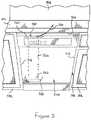
- FIG. 3is a cross section view of an exemplary embodiment of ductwork for the washing machine of FIG. 1 ;
- FIG. 4is a cross section view of another exemplary embodiment of ductwork for the washing machine of FIG. 1 ;
- FIG. 5is a front view of an exemplary embodiment of a dishwasher installed in a cabinet under a countertop;
- FIG. 6is a front view of the dishwasher of FIG. 5 with the front door open;
- FIG. 7is a cross section view of an exemplary embodiment of ductwork for the dishwasher of FIG. 5 .
- interconnectionmay be direct as between the components or may be indirect such as through the use of one or more intermediary components.
- reference to a “member,” “component,” or “portion”shall not be limited to a single structural member, component, or element but can include an assembly of components, members, or elements.
- the illustrated machine 100is front-loading washing machine.
- washing machineis defined to mean a machine designed to wash laundry items, such as clothing, towels, and sheets, that uses water as the primary cleaning agent.
- front-loadingis defined to mean that an internal basket configured to retain laundry items during the washing cycle is oriented in a forward facing direction and that the laundry items enter the basket from a front opening in the washing machine 100 .
- the acoustic ductwork disclosed by this applicationcan be used with any machine having a noise generating component.
- the machine 100may take a wide variety of different forms, such as a clothes washing machine, a dishwasher, an air conditioner, a refrigerator, a freezer, or any other household machine or appliance that makes noise.
- the illustrated washing machine 100includes a cabinet or housing 102 having a top surface 104 , a first side surface 106 , a second side surface 108 opposite the first side surface 106 , a front surface 110 extending between the first and second side surfaces 106 , 108 , and a back surface 112 opposite the front surface 110 .
- the cabinet 102is configured to provide an enclosure for the internal components of the washing machine 100 .
- the cabinet 102can take a variety of different forms.
- the cabinet 102can be made from a wide variety of different materials and/or combinations of materials. Examples of suitable materials for the cabinet 102 include, but are not limited to, plastic, fiberglass reinforced plastic, any type of sheet metal, etc.
- the cabinet 102may have any finish.
- the cabinet 102can be made from stainless steel sheet metal, and can have other desired finishes, such as for example a clear lacquer finish. In some exemplary embodiments, the cabinet 102 is made from sheet metal and covered with a finish such as an enamel based finish.
- the front surface 110 of the cabinetincludes an opening 114 . While the illustrated embodiment shows the cabinet 102 as having a generally rectangular cross-sectional shape, it should be appreciated that the cabinet can have other cross-sectional shapes.
- the washing machine 100includes a tub assembly 122 , a motor assembly 124 and a basket 126 .
- the tub assembly 122is suspended within the cabinet 102 and is configured to retain water used for washing the laundry items.
- the tub assembly 122can take a wide variety of different forms and can be made from a wide variety of different materials.
- the tub assembly 122may be generally cylindrical with a forward-facing opening 128 as shown, but may take a variety of different shapes.
- the tub assembly 122forms an internal compartment 127 the houses the basket 126 .
- the tub assembly 122may be made from plastic/polymeric materials, or metals, such as stainless steel and aluminum.
- the tub assembly 122is made from a material that is resistant to corrosion when exposed to water or at least the inside surface of the tub is coated with a material that is resistant to corrosion when exposed to water.
- the motor assembly 124is operatively connected to the basket 126 and configured to rotate the basket 126 (see FIG. 2 ).
- the motor assembly 124may take a wide variety of different forms and may be operatively coupled to the basket 126 in many different ways, such as for example, by a belt and pulley arrangement.
- the motor assembly 124is mounted onto the back of the tub assembly 122 and is directly coupled to the basket 126 . Operation of the motor assembly 124 , rotation of the basket 126 , and the vibration of the washing machine 100 may be viewed as noise generating sources.
- the basket 126is positioned within the compartment 127 of the tub assembly 122 and configured to retain the laundry items during the washing cycle.
- the basket 126can take a wide variety of different forms and can be made from a wide variety of different materials.
- the basket 126may be generally cylindrical with a forward facing opening as shown, but may take a variety of different shapes.
- the basket 126may be made from plastic/polymeric materials, or metals, such as steel, stainless steel, and aluminum.
- the basket 126is made from a material that is resistant to corrosion when exposed to water or is coated with a material that is resistant to corrosion when exposed to water.
- the washing machine 100may include a user interface 130 .
- the user interface 130may be configured in a variety of ways, including shape, size, orientation, and location on the washing machine 100 .
- the user interface 130is positioned on the front surface 110 in the top right corner.
- the user interface 130includes controls (not shown) to allow the user to operate the washing machine 100 .
- the washing machine 100may also include a detergent dispenser 132 , such as a detergent dispenser drawer.
- the detergent dispenser 132may be configured in a variety of ways, including shape, size, orientation, and location on the washing machine 100 .
- the detergent dispenser 130may include a drawer positioned on the front surface 110 in the top left corner.
- the detergent dispenser 130includes one or more inlets 134 and one or more receptacles 136 that allow a user to load the detergent dispenser 130 with laundry products, such as laundry detergent, bleach, fabric softener, etc., for the controlled release of these products into the basket 126 during a wash cycle.
- the detergent dispenser 130is in fluid communication with the basket 126 by a first duct 140 .
- the first duct 140is a passage that allows the laundry products to selectively flow, or be otherwise transported, into the basket 126 .
- the washing machine 100also includes a second duct 150 that functions as a safety air duct ( FIG. 2 ).
- the second duct 150creates an open (unobstructed) air path from the basket 126 to the exterior of the washing machine 100 .
- the second duct 150extends from the basket 126 to an opening 152 on the back surface 112 of the washing machine 100 .
- the first duct 140 and the second duct 150are illustrated in FIGS. 1-2 as being straight passages with a constant width or diameter.
- the first and second ducts 140 , 150may not be straight passages and may include changes in width or diameter along the length of the ducts.
- the first duct 140 and the second duct 150are made of a plastic or a rubber. This type of material and construction, however, may transmit or otherwise convey unwanted sound along the ducts and to the exterior of the washing machine.
- the first duct 140 and the second duct 150are formed by one or more materials that acoustically dampen or absorb sound from the machine, in particular sound that would typically resonate along the first and second ducts in a conventional washing machine.
- the material used in the first duct 140 and the second duct 150may be configured in a variety of ways. Any material or materials that reduce sound transmission through the ducts 140 , 150 may be used.
- the first duct 140 and the second duct 150include at least one sound absorbing material.
- the first duct 140 and the second duct 150may be made of the same material(s) or may be made of different materials.
- the first duct 140is formed from a multi-layered, waterproof, flexible, sound-absorbing blanket including a first layer 302 , a second layer 304 , and a third layer 306 .
- the first duct 140is illustrated in FIG. 3 as a cylindrical tube having an inner passage 308 with a constant diameter. In some embodiments, however, the first duct 140 may not be straight, may not be cylindrical, and/or may not have a constant diameter or width along its length.
- the first duct 140may include bends or curves, may have a width or diameter of the exterior and/or the inner passage that varies over the length of the first duct 140 , and may have a cross sectional shape that is non-circular and/or varies along the length of the first duct 140 .
- the first duct 140may be any suitable size, shape, orientation, or configuration. Since the first duct 140 may carry liquids from the dispenser 132 to the basket 126 , the first duct 140 will typically include one or more water-proof layers.
- the first layer 302forms an inner surface defining the inner passage 308 .
- the first layer 302may be configured in a variety of ways. Any layer that is water resistant, preferably waterproof, and allows noise energy to pass or transmit through it may be used. In some embodiments, the first layer 302 is both water resistant, or waterproof, and bleach resistant, or bleach proof. For example, in one exemplary embodiment, the first layer 302 is a thin, elastic, water-proof film that allows noise energy to be transmitted through the film to the second layer 304 . Any suitable materials may be used for the first layer 302 . Suitable material for the first layer may include, but not be limited to, polyester, such as Mylar, polypropylene, or other similar materials.
- the first layer 302has a thickness T 1 that is less than or equal to 1 mil.
- the relative thinness of the first layer 302aids in transmitting noise energy through the layer. In other embodiments, however, the thickness T 1 of the first layer may be greater than 1 mil.
- the second layer 304may be configured in a variety of ways.
- the second layer 304is a porous, sound absorbing layer that may be made from a wide variety of different materials.
- the second layer 304may be made from thermoplastic polymers, such as polyester, polyethylene terephthalate (PET), polypropylene, and the like.
- the second layer 304includes a fibrous material such as, for example, air-laid or spunbond polymer or glass fibers.
- the second layer 304includes a fine fiber PET material, such as a 2 denier fiber size PET material.
- the second layer 304may be formed with a variety of different densities and lofts, which can be selected to adjust the acoustic performance of the first duct 140 .
- the second layer 304has a density in the range of 8-150 grams per square foot and a thickness in the range of 3-38 mm. In other embodiments, however, the second layer may have a density greater than 150 grams per square foot or less than 8 grams per square foot and a thickness greater than 38 mm or less than 3 mm. Different combinations of materials, lofts, and densities for the second layer 304 may be selected or changed to achieve different acoustic performance characteristics.
- the first duct 140 and the second duct 150may be configured to attenuate sound energy at a variety of frequencies.
- the first duct 140 and the second duct 150are configured to attenuate low frequency sound energy.
- Low frequency sound energymay be sound energy in a frequency range of 100 to 800 Hz, a frequency range of 100 to 400 Hz, a frequency range of 100 to 200 Hz, a frequency range of 100 to 150 Hz, or a frequency range of 100 to 125 Hz.
- the first duct 140 and the second duct 150are configured to attenuate high frequency sound energy.
- High frequency sound energymay be sound energy at a frequency that is higher than 800 Hz.
- the third layer 306may be configured in a variety of ways.
- the materials used in the third layer 306may be selected to serve different functions in different embodiments, such as abrasion resistance and noise transmission or reflection.
- the third layer 306may be a breathable layer having a porosity and thickness configured to allow noise energy to be transmitted through the third layer 306 .
- the third layer 306may be selected to allow noise within only a certain frequency range to transmit through the third layer 306 .
- the third layer 306may be a noise reflective layer configured to reflect noise back into the second layer 304 .
- the material or materials used in the third layer 306may be any suitable material the performs the desired function. For example, if the third layer 306 is configured to reflect noise back into second layer 304 , any suitable noise reflecting material may be used. Similarly, if the third layer 306 is configured to allow noise to transmit through the third layer 306 , any suitable material that allows noise to transmit through the third layer 306 may be used. For example, the third layer 306 may be the same or similar material to the first layer 402 of the second duct 150 , described below.
- the third layer 306may be a polymer film, such as polyester or polypropylene, having a thickness T 3 .
- Thin filmssuch as films having a thickness at or below 2 mils, may be suitable for allowing some noise energy to be transmitted through the third layer 306 .
- the third layer 306has a thickness T 3 in the range of 0.5-2.0 mils, or 0.5-1.0 mils, or about 0.7 mils.
- Thicker filmssuch as films having a thickness greater than 2 mils, may be suitable for reflecting noise energy back into the second layer 304 .
- the third layer 306has a thickness T 3 greater than 2.0 mils, or greater than 3.0 mils, or greater than 5.0 mils.
- the third layer 306is an air barrier having an airflow resistance at or greater than about 3000 Rayls.
- the second duct 150is a multi-layered, breathable, flexible material including a first layer 402 , a second layer 404 , and an optional third layer 406 .
- the second duct 150is illustrated in FIG. 4 as a cylindrical tube having an inner passage 408 with a constant diameter. In some embodiments, however, the second duct 150 may not be straight, may not be cylindrical, and/or may not have a constant diameter.
- the second duct 150may include bends or curves, may have a width or diameter of the exterior and/or the inner passage 408 that varies over the length of the second duct 150 , and may have a cross sectional shape that is non-circular and/or varies along the length of the second duct 150 .
- the second duct 150may be any suitable size, shape, orientation, or configuration. Since the second duct 150 is a safety air vent for the basket 126 , the second duct 150 may include an air flow control layer.
- the first layer 402forms an inner surface defining the inner passage 408 .
- the first layer 402may be configured in a variety of ways.
- the first layer 402is a relatively permeable layer that allows noise and air to pass through the first layer 402 .
- the first layer 402may have an airflow resistance between about 600-1400 Rayls.
- the first layer 402may have an airflow resistance between 900-1400 Rayls.
- the first layer 402may be selected to have an airflow resistance of about 900 Rayls, about 1100 Rayls, or about 1400 Rayls. However, other airflow resistances can be selected.
- the first layer 402 in the embodiment illustrated by FIG. 4may have an airflow resistance of about 900, 1100, and/or 1400 Rayls.
- the first layer 402can be made from a wide variety of different materials and may have a variety of different thicknesses. For example, any material having the airflow resistance described above can be used.
- acceptable materials for the first layer 402include, but are not limited to polypropylene, PET, non-porous materials that are perforated to allow airflow, such as perforated metal foil, perforated polymer material, such as a Teflon sheet that has been perforated to allow airflow.
- acceptable materials for the first layer 402include, but are not limited to non-porous materials that are not perforated to allow airflow, such as metal foil, polymer material, such as a Teflon sheet.
- the first layer 402may have a wide variety of different densities and thicknesses. In an exemplary embodiment, the first layer 402 is much denser than the second layer 404 .
- the first layer 402may be a polypropylene, polyester, and/or PET (Polyethylene terephthalate) material, such as a spunbond/meltblown/spunbond sheet that is 50 grams per square meter (gsm).
- the first layer 402has a thickness T 4 that is at or below 2 mils, or in the range of 0.5-2.0 mils, or 0.5-1.0 mils, or at about 0.7 mils.
- the second layer 404may be configured m a variety of ways.
- the second layer 404may be the same sound absorbing material as the second layer 304 of the first duct 140 .
- the second layer 404has a thickness T 5 in the range of 3-38 mm.
- the third layer 406may be configured in a variety of ways.
- the third layer 406may be selected from a material described above in relation to the third layer 306 of the embodiment of FIG. 3 .
- the description of the third layer 306applies equally to the third layer 406 .
- the materials used in the third layer 406may be selected to serve different functions in different embodiments, such as abrasion resistance and noise transmission or reflection.
- the third layer 406may be a breathable layer having a porosity and thickness configured to allow noise energy to be transmitted through the third layer 406 .
- the third layer 406may be selected to allow noise within only a certain frequency range to transmit through the third layer 406 .
- the third layer 406may be a noise reflective layer configured to reflect noise back into the second layer 404 .
- the first duct 140is in fluid communication with the basket 126 such that laundry products may be directed into the basket 126 during a wash cycle.
- the second ductplaces the basket 126 into fluid communication with an area external to the washing machine to provide an open-air passage (i.e., child safety air vent).
- the construction of the first duct 140 and the second duct 150reduce or eliminate unwanted sound from the mechanical components of the washing machine and/or vibration of the machine, transmitted through the first and second duct 140 , 150 to the exterior area surrounding the machine.
- FIG. 5illustrates a dishwasher 500 installed between cabinets 502 and under a countertop 504 .
- a cavity 506 that the dishwasher 500 is installed inis bounded by the sides 512 of the cabinets 502 , by the bottom 514 of the countertop 504 , and by a wall 508 of the kitchen.
- the dishwasher 500includes a housing 518 and a front door 520 pivotably coupled to the housing 518 .
- the dishwasher 500may include an inner compartment or tub 522 defined by a plurality of inner side surfaces 524 associated with the housing 518 and an inner side surface 526 of the front door 520 .
- the inner compartment 522may include a heating element 528 .
- the dishwasher 500also includes an exhaust duct 550 .
- the exhaust duct 150allows gas, such as water vapor that forms when water is heated in the washing and drying cycles of the dishwasher, to exit the dishwasher 500 as indicated by arrow 560 .
- the exhaust duct 550may be configured in a variety of ways and can take a wide variety of different forms.
- the exhaust duct 550may be positioned through the front door 504 as illustrated in FIGS. 5-6 . In other embodiments, however, the exhaust duct 550 may be provided at other locations on the dishwasher 550 , such as through one or more of the inner side surfaces 524 of the housing 518 .
- dishwasherincludes an inlet 562 positioned at or near the bottom of the front door 520 and an outlet 564 positioned at or near the top of the front door 520 .
- the inlet 562 and the outlet 564are rectangular. In other embodiment, however the inlet 562 and the outlet 564 may be other than rectangular and can be any suitable shape(s).
- the exhaust duct 550defines a passage 566 (shown as dashed lines in FIGS. 5-6 ) extending upward within the front door 520 and in fluid communication with the inner compartment 522 via the inlet 562 , and in fluid communication with an area exterior of the housing 518 via the outlet 564 .
- the passage 566is illustrated as straight. In other embodiments, however, the passage 566 may include curved, corners, or other non-linear portions.
- the material used in the exhaust duct 550may be configured in a variety of ways. Any material or materials that reduce sound transmission through the exhaust duct 550 may be used.
- the exhaust duct 550includes at least one sound absorbing material.
- the exhaust duct 550may be configured the same as the first duct 140 or the second duct 150 . In other embodiments, however, the exhaust duct 550 may include one or more materials different than the first duct 140 or the second duct 150 .
- the exhaust duct 550is formed from a multi-layered, waterproof, flexible, sound-absorbing blanket including a first layer 702 , a second layer 704 , and a third layer 706 .
- the exhaust duct 550is illustrated in FIG. 7 as a cylindrical tube having with the passage 566 having a constant diameter. In some embodiments, however, the exhaust duct 550 may not be straight, may not be cylindrical, and/or may not have a constant diameter or width along its length.
- the exhaust duct 550may include bends or curves, may have a width or diameter of the exterior and/or the inner passage that varies over the length of the exhaust duct 550 , and may have a cross sectional shape that is non-circular and/or varies along the length of the exhaust duct 550 .
- the exhaust duct 550may be any suitable size, shape, orientation, or configuration.
- the exhaust duct 550is generally cylindrical, but, to fit within the front door 520 , the exhaust duct 550 is flattened, without obstructing the passage 566 , to a profile with a width greater than a thickness. Further, the exhaust duct 550 is sufficiently flexible to be shaped to complement the rectangle shape of the inlet 562 and the outlet 564 where the exhaust duct 550 meets up with the inlet 562 and the outlet 564 .
- the exhaust duct 550may carry moist air from inner compartment 522 , such as during the drying cycle, the exhaust duct 550 will typically include one or more water-proof layers.
- the first layer 702forms an inner surface defining the passage 566 .
- the first layer 702may be configured in a variety of ways. Any layer that is water resistant, preferably waterproof, and allows noise energy to pass or transmit through it may be used.
- the first layer 702is a thin, elastic, water-proof film that allows noise energy to be transmitted through the film to the second layer 704 . Any suitable materials may be used for the first layer 702 . Suitable material for the first layer 702 may include, but not be limited to, polyester, such as Mylar, polypropylene, or other similar materials.
- the first layer 702has a thickness T 1 that is less than or equal to 1 mil. The relative thinness of the first layer 702 aids in transmitting noise energy through the layer. In other embodiments, however, the thickness T 1 of the first layer 702 may be greater than 1 mil.
- the second layer 704may be configured in a variety of ways.
- the second layer 704is a porous, sound absorbing layer that may be made from a wide variety of different materials.
- the second layer 304may be made from thermoplastic polymers, such as polyester, polyethylene terephthalate (PET), polypropylene, and the like.
- the second layer 704includes a fibrous material such as, for example, air-laid or spunbond polymer or glass fibers.
- the second layer 704includes a fine fiber PET material, such as a 2 denier fiber size PET material.
- the second layer 704may be formed with a variety of different densities and lofts, which can be selected to adjust the acoustic performance of the exhaust duct 550 .
- the second layer 704has a density in the range of 8-150 grams per square foot and a thickness in the range of 3-38 mm. In other embodiments, however, the second layer 704 may have a density greater than 150 grams per square foot or less than 8 grams per square foot and a thickness greater than 38 mm or less than 3 mm.
- Different combinations of materials, lofts, and densities for the second layer 304may be selected or changed to achieve different acoustic performance characteristics.
- the exhaust duct 550may be configured to attenuate sound energy at a variety of frequencies.
- the exhaust duct 550is configured to attenuate low frequency sound energy.
- Low frequency sound energymay be sound energy in a frequency range of 100 to 800 Hz, a frequency range of 100 to 400 Hz, a frequency range of 100 to 200 Hz, a frequency range of 100 to 150 Hz, or a frequency range of 100 to 125 Hz.
- the exhaust duct 550is configured to attenuate high frequency sound energy.
- High frequency sound energymay be sound energy at a frequency that is higher than 800 Hz.
- the exhaust duct 550may be configured in a variety of ways.
- the materials used in the exhaust duct 550may be selected to serve different functions in different embodiments, such as abrasion resistance and noise transmission or reflection.
- the third layer 706may be a breathable layer having a porosity and thickness configured to allow noise energy to be transmitted through the third layer 706 .
- the third layer 706may be selected to allow noise within only a certain frequency range to transmit through the third layer 706 .
- the third layer 706may be a noise reflective layer configured to reflect noise back into the second layer 704 .
- the material or materials used in the third layer 706may be any suitable material the performs the desired function. For example, if the third layer 706 is configured to reflect noise back into second layer 704 , any suitable noise reflecting material may be used. Similarly, if the third layer 706 is configured to allow noise to transmit through the third layer 706 , any suitable material that allows noise to transmit through the third layer 706 may be used. For example, the third layer 706 may be the same or similar material to the first layer 402 of the second duct 150 .
- the third layer 706may be a polymer film, such as polyester or polypropylene, having a thickness T 3 .
- Thin filmssuch as films having a thickness at or below 2 mils, may be suitable for allowing some noise energy to be transmitted through the third layer 306 .
- the third layer 706has a thickness T 3 in the range of 0.5-2.0 mils, or 0.5-1.0 mils, or about 0.7 mils.
- Thicker filmssuch as films having a thickness greater than 2 mils, may be suitable for reflecting noise energy back into the second layer 704 .
- the third layer 306has a thickness T 3 greater than 2.0 mils, or greater than 3.0 mils, or greater than 5.0 mils.
- the third layer 706is an air barrier having an airflow resistance at or greater than about 3000 Rayls.
- the exhaust duct 550is in fluid communication with the inner compartment 522 and places the inner compartment 522 into fluid communication with an area external to the dishwasher 500 .
- the dishwasher 500may include a drying cycle at the end of a wash cycle.
- the heating element 528or another heating source, may also be utilized to heat the air inside the inner compartment 522 to assist in the drying of contents within the inner compartment 522 .
- Water vaporized by the heati.e., steam
- Some of the vaporized watermay also condense in the exhaust duct 550 and flow back into the inner compartment 522 and out of a drain at the bottom of the inner compartment 522 .
- the construction of the exhaust duct 550reduces or eliminates unwanted sound from the dishwasher that can be transmitted through the exhaust duct 550 to the exterior area surrounding the machine.
Landscapes
- Engineering & Computer Science (AREA)
- Textile Engineering (AREA)
- Detail Structures Of Washing Machines And Dryers (AREA)
Abstract
Description
Claims (20)
Priority Applications (1)
| Application Number | Priority Date | Filing Date | Title |
|---|---|---|---|
| US15/965,225US10980391B2 (en) | 2017-04-28 | 2018-04-27 | Appliance with acoustically insulated ductwork |
Applications Claiming Priority (2)
| Application Number | Priority Date | Filing Date | Title |
|---|---|---|---|
| US201762491575P | 2017-04-28 | 2017-04-28 | |
| US15/965,225US10980391B2 (en) | 2017-04-28 | 2018-04-27 | Appliance with acoustically insulated ductwork |
Publications (2)
| Publication Number | Publication Date |
|---|---|
| US20180310796A1 US20180310796A1 (en) | 2018-11-01 |
| US10980391B2true US10980391B2 (en) | 2021-04-20 |
Family
ID=63915767
Family Applications (1)
| Application Number | Title | Priority Date | Filing Date |
|---|---|---|---|
| US15/965,225Active2038-11-24US10980391B2 (en) | 2017-04-28 | 2018-04-27 | Appliance with acoustically insulated ductwork |
Country Status (1)
| Country | Link |
|---|---|
| US (1) | US10980391B2 (en) |
Families Citing this family (1)
| Publication number | Priority date | Publication date | Assignee | Title |
|---|---|---|---|---|
| US20190360144A1 (en)* | 2018-05-24 | 2019-11-28 | Haier Us Appliance Solutions, Inc. | Washing machine appliance having a selective ventilation damper |
Citations (75)
| Publication number | Priority date | Publication date | Assignee | Title |
|---|---|---|---|---|
| US1190292A (en) | 1915-08-27 | 1916-07-11 | Mechanical Rubber Co | Process of making hose. |
| US2089492A (en) | 1935-07-06 | 1937-08-10 | American Radiator Co | Duct |
| US2253310A (en) | 1938-12-14 | 1941-08-19 | Hoover Co | Suction cleaner |
| US2328236A (en) | 1939-12-07 | 1943-08-31 | Hoover Co | Suction cleaner |
| US2489048A (en) | 1947-12-03 | 1949-11-22 | Johns Manville | Insulated duct |
| US2534811A (en) | 1946-09-03 | 1950-12-19 | Corlett Turner Co | Silent stock tubing |
| US3000464A (en) | 1957-09-18 | 1961-09-19 | Bolt Beranek & Newman | Acoustic absorber |
| US3019850A (en) | 1958-04-08 | 1962-02-06 | John J March | Prefabricated insulated duct and sound trap |
| US3132717A (en) | 1955-05-27 | 1964-05-12 | Bolt Beranek & Newman | Acoustically absorbent conduit |
| US3175586A (en) | 1960-08-15 | 1965-03-30 | Tatsch Richard | Conduit and method of manufacture |
| US3374856A (en) | 1966-09-09 | 1968-03-26 | Garrett Corp | Flexible sound attenuating duct with foamed plastic lining |
| US3552445A (en) | 1969-04-18 | 1971-01-05 | Seefore Corp | Insulated pipe assembly |
| US3570545A (en) | 1967-09-29 | 1971-03-16 | Benteler Werke Ag | Insulated tube and method of making the same |
| US3768523A (en) | 1971-06-09 | 1973-10-30 | C Schroeder | Ducting |
| US3807420A (en) | 1972-05-15 | 1974-04-30 | Westinghouse Electric Corp | Dishwasher drying system |
| US3903928A (en) | 1972-08-15 | 1975-09-09 | Smiths Industries Ltd | Vehicle exhaust tubing |
| US4121686A (en) | 1977-06-09 | 1978-10-24 | Keller Jr Moreau A | Hollow sound-dampened structure |
| US4190131A (en) | 1977-02-16 | 1980-02-26 | Delta Materials Research Limited | Noise abatement techniques and systems |
| US4404992A (en) | 1980-09-09 | 1983-09-20 | Nippon Steel Corporation | Composite dual tubing |
| US4421202A (en) | 1981-03-20 | 1983-12-20 | Peabody Abc Corporation | Sound attenuator |
| US4442585A (en) | 1982-03-31 | 1984-04-17 | Mcgehee Sr Fred N | Method of construction for thermal and acoustic insulation blankets |
| US4508486A (en) | 1982-05-28 | 1985-04-02 | Peabody Abc Corporation | Ventilation fan with noise-attenuating housing |
| US4596921A (en) | 1984-05-22 | 1986-06-24 | Hersh Alan S | Low noise hand-held hairdryer |
| US4615411A (en) | 1982-05-27 | 1986-10-07 | Dynamit Nobel Ag | Sound-insulated flow duct and process for the manufacture thereof |
| US4752431A (en) | 1984-05-16 | 1988-06-21 | Knowles Albert H | Permanent conforming pipe for conducting fluids and the like and method for producing the same |
| US4788090A (en) | 1986-04-02 | 1988-11-29 | Shell Internationale Research Maatschappij B.V. | Fire resistant plastic pipe |
| GB2253035A (en) | 1991-02-18 | 1992-08-26 | Zanussi Elettrodomestici | Silenced tumble dryer |
| US5162622A (en) | 1988-06-15 | 1992-11-10 | Dorchester Enterprises Ltd. | Exhaust silencer |
| US5400830A (en) | 1992-11-12 | 1995-03-28 | Ford Motor Company | Composite automotive exhaust pipe |
| US5428973A (en) | 1992-11-13 | 1995-07-04 | Kabushiki Kaisha Toshiba | Refrigerator with meandering air duct for wire and tube condenser |
| US5487412A (en) | 1993-05-26 | 1996-01-30 | Schuller International, Inc. | Glass fiber airduct with coated interior surface containing a biocide |
| US5548093A (en) | 1993-08-20 | 1996-08-20 | Toyoda Gosei Co., Ltd. | Low noise hose |
| US5731557A (en) | 1995-12-20 | 1998-03-24 | Richard Norres | Fluid guiding element for blocking and damping noise propagating in main passages |
| US5795634A (en) | 1995-09-22 | 1998-08-18 | Totaku Industries, Inc. | Heat insulating noise reducing duct |
| US5801342A (en) | 1997-01-27 | 1998-09-01 | Lindab Ab | Double-walled structure and method and arrangement for producing the same |
| WO1999017047A1 (en) | 1997-09-29 | 1999-04-08 | Shishiai-Kabushikigaisha | Sound-proof pipe member |
| WO1999017048A1 (en) | 1997-10-01 | 1999-04-08 | Shishiai-Kabushikigaisha | Fire-resistant sound-proof pipe |
| US5918644A (en) | 1996-05-23 | 1999-07-06 | Haack; C. William | Air duct and method of making same |
| US5965851A (en) | 1997-01-28 | 1999-10-12 | Owens Corning Fiberglas Technology, Inc. | Acoustically insulated apparatus |
| US6062270A (en) | 1997-01-27 | 2000-05-16 | Lindab Ab | Double-walled structure in a ventilation duct system |
| US6179009B1 (en) | 1998-09-16 | 2001-01-30 | Totaku Industries, Inc. | Heat-insulating and noise reducing duct |
| US6202702B1 (en)* | 2000-01-06 | 2001-03-20 | Shishiai-Kabushikigaisha | Acoustic damping pipe cover |
| US6234211B1 (en) | 1997-04-30 | 2001-05-22 | Westaflex Automobile | Pipe for the ducting of gaseous fluids notably in cars |
| US6273144B1 (en) | 2001-05-16 | 2001-08-14 | Atlantic Richfield Company | Method for inhibiting external corrosion on an insulated pipeline |
| US20010015302A1 (en) | 2000-02-22 | 2001-08-23 | Lindab Ab | Double-walled structure and method of producing the same |
| US6305429B1 (en) | 1996-10-21 | 2001-10-23 | Corus Uk Limited | Double walled pipe structures |
| US6324720B1 (en) | 1998-03-10 | 2001-12-04 | The Toro Company | Portable blower tube noise reduction |
| US6425419B1 (en) | 2001-08-22 | 2002-07-30 | Sharon L. Attra | Flexible air ducting |
| US20020134615A1 (en)* | 2001-02-21 | 2002-09-26 | Herreman Kevin Michael | Noise reduction system for kitchen |
| US6543575B1 (en) | 2000-06-14 | 2003-04-08 | Lindab Ab | Double-walled structure and connection arrangement |
| US6782922B1 (en) | 2003-05-30 | 2004-08-31 | John Manville International, Inc. | Coated fibrous pipe insulation system |
| US20050092384A1 (en) | 2003-10-29 | 2005-05-05 | Superior Air Ducts | Semi-flexible air duct |
| US7028416B1 (en) | 2003-04-21 | 2006-04-18 | Darryl D Dobie | Noise attenuating drying apparatus for motor vehicles |
| US20060169341A1 (en) | 2005-02-01 | 2006-08-03 | Material Sciences Corporation | Internally damped laminated tube |
| US7159620B2 (en) | 2002-09-04 | 2007-01-09 | Knauf Insulation Gmbh | Pipe blanket to fit a variety of pipe diameters |
| US20080001431A1 (en)* | 2006-06-30 | 2008-01-03 | 3M Innovative Properties Company | Sound insulation constructions and methods of using the same |
| US20080196266A1 (en) | 2007-02-20 | 2008-08-21 | Han-Yong Jung | Ductless dryer |
| US20090269219A1 (en) | 2005-07-29 | 2009-10-29 | Bsh Bosch Und Siemens Hausgerate Gmbh | Domestic appliance with a sound damper |
| US20100071797A1 (en) | 2008-09-25 | 2010-03-25 | Jungers Jon W | Fire retardant air handling system ductwork component and method of manufacture |
| US7754122B2 (en) | 2001-09-28 | 2010-07-13 | Johns Manville | Equipment and duct liner insulation and method |
| US8015848B2 (en) | 2009-01-22 | 2011-09-13 | Electrolux Home Products, Inc. | Acoustic panel |
| WO2012097948A2 (en) | 2011-01-17 | 2012-07-26 | BSH Bosch und Siemens Hausgeräte GmbH | Refrigerator and method for producing a refrigerator |
| US8257812B2 (en) | 2009-11-26 | 2012-09-04 | Hyundai Motor Company | Low-noise plastic intercooler pipe having multi-layered structure |
| US8371338B2 (en) | 2008-09-23 | 2013-02-12 | Armacell Enterprise Gmbh | Foam insulation structure and method for insulating annular ducts |
| US8459407B2 (en) | 2008-10-01 | 2013-06-11 | General Electric Company | Sound attenuation systems and methods |
| US20130291990A1 (en) | 2012-05-02 | 2013-11-07 | Owens Corning Intellectual Capital, Llc | Duct insulation laminates and methods of manufacturing and installation |
| US20140060597A1 (en)* | 2012-09-05 | 2014-03-06 | Whirlpool Corporation | Dishwasher |
| US8739837B2 (en) | 2010-10-20 | 2014-06-03 | Isolite Gmbh | Insulating molded part |
| US8899377B2 (en) | 2009-12-14 | 2014-12-02 | Airbus Operations Gmbh | Acoustically optimized air conditioning components |
| US9145997B2 (en) | 2013-09-27 | 2015-09-29 | Hyundai Motor Company | Mold for making sound-absorbing duct and sound-absorbing duct using the same |
| US20160265797A1 (en) | 2015-02-19 | 2016-09-15 | Abd Creative Solutions, Llc | Appliance vent |
| US9714480B2 (en)* | 2011-05-24 | 2017-07-25 | Owens Corning Intellectual Capital, Llc | Acoustically insulated machine |
| US20170258291A1 (en) | 2016-03-09 | 2017-09-14 | Whirlpool Corporation | Dishwasher with sound attenuation toe kick panel |
| US20170258292A1 (en)* | 2016-03-09 | 2017-09-14 | Whirlpool Corporation | Dishwasher with a multi-layer acoustic material in a condensing drying system |
| US9784469B2 (en) | 2015-05-20 | 2017-10-10 | Rite-Hite Holding Corporation | Fabric silencers for air ducts |
- 2018
- 2018-04-27USUS15/965,225patent/US10980391B2/enactiveActive
Patent Citations (76)
| Publication number | Priority date | Publication date | Assignee | Title |
|---|---|---|---|---|
| US1190292A (en) | 1915-08-27 | 1916-07-11 | Mechanical Rubber Co | Process of making hose. |
| US2089492A (en) | 1935-07-06 | 1937-08-10 | American Radiator Co | Duct |
| US2253310A (en) | 1938-12-14 | 1941-08-19 | Hoover Co | Suction cleaner |
| US2328236A (en) | 1939-12-07 | 1943-08-31 | Hoover Co | Suction cleaner |
| US2534811A (en) | 1946-09-03 | 1950-12-19 | Corlett Turner Co | Silent stock tubing |
| US2489048A (en) | 1947-12-03 | 1949-11-22 | Johns Manville | Insulated duct |
| US3132717A (en) | 1955-05-27 | 1964-05-12 | Bolt Beranek & Newman | Acoustically absorbent conduit |
| US3000464A (en) | 1957-09-18 | 1961-09-19 | Bolt Beranek & Newman | Acoustic absorber |
| US3019850A (en) | 1958-04-08 | 1962-02-06 | John J March | Prefabricated insulated duct and sound trap |
| US3175586A (en) | 1960-08-15 | 1965-03-30 | Tatsch Richard | Conduit and method of manufacture |
| US3374856A (en) | 1966-09-09 | 1968-03-26 | Garrett Corp | Flexible sound attenuating duct with foamed plastic lining |
| US3570545A (en) | 1967-09-29 | 1971-03-16 | Benteler Werke Ag | Insulated tube and method of making the same |
| US3717527A (en) | 1967-09-29 | 1973-02-20 | Benteler Werke Ag | Method of making an insulated tube |
| US3552445A (en) | 1969-04-18 | 1971-01-05 | Seefore Corp | Insulated pipe assembly |
| US3768523A (en) | 1971-06-09 | 1973-10-30 | C Schroeder | Ducting |
| US3807420A (en) | 1972-05-15 | 1974-04-30 | Westinghouse Electric Corp | Dishwasher drying system |
| US3903928A (en) | 1972-08-15 | 1975-09-09 | Smiths Industries Ltd | Vehicle exhaust tubing |
| US4190131A (en) | 1977-02-16 | 1980-02-26 | Delta Materials Research Limited | Noise abatement techniques and systems |
| US4121686A (en) | 1977-06-09 | 1978-10-24 | Keller Jr Moreau A | Hollow sound-dampened structure |
| US4404992A (en) | 1980-09-09 | 1983-09-20 | Nippon Steel Corporation | Composite dual tubing |
| US4421202A (en) | 1981-03-20 | 1983-12-20 | Peabody Abc Corporation | Sound attenuator |
| US4442585A (en) | 1982-03-31 | 1984-04-17 | Mcgehee Sr Fred N | Method of construction for thermal and acoustic insulation blankets |
| US4615411A (en) | 1982-05-27 | 1986-10-07 | Dynamit Nobel Ag | Sound-insulated flow duct and process for the manufacture thereof |
| US4508486A (en) | 1982-05-28 | 1985-04-02 | Peabody Abc Corporation | Ventilation fan with noise-attenuating housing |
| US4752431A (en) | 1984-05-16 | 1988-06-21 | Knowles Albert H | Permanent conforming pipe for conducting fluids and the like and method for producing the same |
| US4596921A (en) | 1984-05-22 | 1986-06-24 | Hersh Alan S | Low noise hand-held hairdryer |
| US4788090A (en) | 1986-04-02 | 1988-11-29 | Shell Internationale Research Maatschappij B.V. | Fire resistant plastic pipe |
| US5162622A (en) | 1988-06-15 | 1992-11-10 | Dorchester Enterprises Ltd. | Exhaust silencer |
| GB2253035A (en) | 1991-02-18 | 1992-08-26 | Zanussi Elettrodomestici | Silenced tumble dryer |
| US5400830A (en) | 1992-11-12 | 1995-03-28 | Ford Motor Company | Composite automotive exhaust pipe |
| US5428973A (en) | 1992-11-13 | 1995-07-04 | Kabushiki Kaisha Toshiba | Refrigerator with meandering air duct for wire and tube condenser |
| US5487412A (en) | 1993-05-26 | 1996-01-30 | Schuller International, Inc. | Glass fiber airduct with coated interior surface containing a biocide |
| US5548093A (en) | 1993-08-20 | 1996-08-20 | Toyoda Gosei Co., Ltd. | Low noise hose |
| US5795634A (en) | 1995-09-22 | 1998-08-18 | Totaku Industries, Inc. | Heat insulating noise reducing duct |
| US5731557A (en) | 1995-12-20 | 1998-03-24 | Richard Norres | Fluid guiding element for blocking and damping noise propagating in main passages |
| US5918644A (en) | 1996-05-23 | 1999-07-06 | Haack; C. William | Air duct and method of making same |
| US6305429B1 (en) | 1996-10-21 | 2001-10-23 | Corus Uk Limited | Double walled pipe structures |
| US5801342A (en) | 1997-01-27 | 1998-09-01 | Lindab Ab | Double-walled structure and method and arrangement for producing the same |
| US6062270A (en) | 1997-01-27 | 2000-05-16 | Lindab Ab | Double-walled structure in a ventilation duct system |
| US5965851A (en) | 1997-01-28 | 1999-10-12 | Owens Corning Fiberglas Technology, Inc. | Acoustically insulated apparatus |
| US6234211B1 (en) | 1997-04-30 | 2001-05-22 | Westaflex Automobile | Pipe for the ducting of gaseous fluids notably in cars |
| WO1999017047A1 (en) | 1997-09-29 | 1999-04-08 | Shishiai-Kabushikigaisha | Sound-proof pipe member |
| WO1999017048A1 (en) | 1997-10-01 | 1999-04-08 | Shishiai-Kabushikigaisha | Fire-resistant sound-proof pipe |
| US6324720B1 (en) | 1998-03-10 | 2001-12-04 | The Toro Company | Portable blower tube noise reduction |
| US6179009B1 (en) | 1998-09-16 | 2001-01-30 | Totaku Industries, Inc. | Heat-insulating and noise reducing duct |
| US6202702B1 (en)* | 2000-01-06 | 2001-03-20 | Shishiai-Kabushikigaisha | Acoustic damping pipe cover |
| US20010015302A1 (en) | 2000-02-22 | 2001-08-23 | Lindab Ab | Double-walled structure and method of producing the same |
| US6543575B1 (en) | 2000-06-14 | 2003-04-08 | Lindab Ab | Double-walled structure and connection arrangement |
| US20020134615A1 (en)* | 2001-02-21 | 2002-09-26 | Herreman Kevin Michael | Noise reduction system for kitchen |
| US6273144B1 (en) | 2001-05-16 | 2001-08-14 | Atlantic Richfield Company | Method for inhibiting external corrosion on an insulated pipeline |
| US6425419B1 (en) | 2001-08-22 | 2002-07-30 | Sharon L. Attra | Flexible air ducting |
| US7754122B2 (en) | 2001-09-28 | 2010-07-13 | Johns Manville | Equipment and duct liner insulation and method |
| US7159620B2 (en) | 2002-09-04 | 2007-01-09 | Knauf Insulation Gmbh | Pipe blanket to fit a variety of pipe diameters |
| US7028416B1 (en) | 2003-04-21 | 2006-04-18 | Darryl D Dobie | Noise attenuating drying apparatus for motor vehicles |
| US6782922B1 (en) | 2003-05-30 | 2004-08-31 | John Manville International, Inc. | Coated fibrous pipe insulation system |
| US20050092384A1 (en) | 2003-10-29 | 2005-05-05 | Superior Air Ducts | Semi-flexible air duct |
| US20060169341A1 (en) | 2005-02-01 | 2006-08-03 | Material Sciences Corporation | Internally damped laminated tube |
| US20090269219A1 (en) | 2005-07-29 | 2009-10-29 | Bsh Bosch Und Siemens Hausgerate Gmbh | Domestic appliance with a sound damper |
| US20080001431A1 (en)* | 2006-06-30 | 2008-01-03 | 3M Innovative Properties Company | Sound insulation constructions and methods of using the same |
| US20080196266A1 (en) | 2007-02-20 | 2008-08-21 | Han-Yong Jung | Ductless dryer |
| US8371338B2 (en) | 2008-09-23 | 2013-02-12 | Armacell Enterprise Gmbh | Foam insulation structure and method for insulating annular ducts |
| US20100071797A1 (en) | 2008-09-25 | 2010-03-25 | Jungers Jon W | Fire retardant air handling system ductwork component and method of manufacture |
| US8459407B2 (en) | 2008-10-01 | 2013-06-11 | General Electric Company | Sound attenuation systems and methods |
| US8015848B2 (en) | 2009-01-22 | 2011-09-13 | Electrolux Home Products, Inc. | Acoustic panel |
| US8257812B2 (en) | 2009-11-26 | 2012-09-04 | Hyundai Motor Company | Low-noise plastic intercooler pipe having multi-layered structure |
| US8899377B2 (en) | 2009-12-14 | 2014-12-02 | Airbus Operations Gmbh | Acoustically optimized air conditioning components |
| US8739837B2 (en) | 2010-10-20 | 2014-06-03 | Isolite Gmbh | Insulating molded part |
| WO2012097948A2 (en) | 2011-01-17 | 2012-07-26 | BSH Bosch und Siemens Hausgeräte GmbH | Refrigerator and method for producing a refrigerator |
| US9714480B2 (en)* | 2011-05-24 | 2017-07-25 | Owens Corning Intellectual Capital, Llc | Acoustically insulated machine |
| US20130291990A1 (en) | 2012-05-02 | 2013-11-07 | Owens Corning Intellectual Capital, Llc | Duct insulation laminates and methods of manufacturing and installation |
| US20140060597A1 (en)* | 2012-09-05 | 2014-03-06 | Whirlpool Corporation | Dishwasher |
| US9145997B2 (en) | 2013-09-27 | 2015-09-29 | Hyundai Motor Company | Mold for making sound-absorbing duct and sound-absorbing duct using the same |
| US20160265797A1 (en) | 2015-02-19 | 2016-09-15 | Abd Creative Solutions, Llc | Appliance vent |
| US9784469B2 (en) | 2015-05-20 | 2017-10-10 | Rite-Hite Holding Corporation | Fabric silencers for air ducts |
| US20170258291A1 (en) | 2016-03-09 | 2017-09-14 | Whirlpool Corporation | Dishwasher with sound attenuation toe kick panel |
| US20170258292A1 (en)* | 2016-03-09 | 2017-09-14 | Whirlpool Corporation | Dishwasher with a multi-layer acoustic material in a condensing drying system |
Also Published As
| Publication number | Publication date |
|---|---|
| US20180310796A1 (en) | 2018-11-01 |
Similar Documents
| Publication | Publication Date | Title |
|---|---|---|
| US9714480B2 (en) | Acoustically insulated machine | |
| KR101964644B1 (en) | Appliance having a noise reduction device | |
| US9453296B2 (en) | Acoustically insulated machine | |
| US9931016B2 (en) | Dishwasher insulation blanket | |
| US7981222B2 (en) | Dishwasher having sound attenuating structures | |
| US12035867B2 (en) | Acoustically insulated machine | |
| US20070272285A1 (en) | Appliance noise reduction blanket | |
| EP1025302B1 (en) | Noise abatement for appliance | |
| US9427133B2 (en) | Dishwasher insulation blanket | |
| CN102587091A (en) | Drain hose and washer having the same | |
| US9474431B2 (en) | Sound abatement for a dishwasher appliance | |
| US10980391B2 (en) | Appliance with acoustically insulated ductwork | |
| EP1358836B1 (en) | Low-noise in-sink dishwasher | |
| WO2012161695A1 (en) | Acoustically insulated machine | |
| KR20120079793A (en) | Drain hose and washer having the same | |
| US20050079739A1 (en) | Housing part of a domestic appliance | |
| US11666199B2 (en) | Appliance with cellulose-based insulator | |
| KR920000716B1 (en) | Rotary machine | |
| KR20250098837A (en) | Laundry treating apparatus | |
| KR20250098835A (en) | Laundry treating apparatus |
Legal Events
| Date | Code | Title | Description |
|---|---|---|---|
| FEPP | Fee payment procedure | Free format text:ENTITY STATUS SET TO UNDISCOUNTED (ORIGINAL EVENT CODE: BIG.); ENTITY STATUS OF PATENT OWNER: LARGE ENTITY | |
| AS | Assignment | Owner name:OWENS CORNING INTELLECTUAL CAPITAL, LLC, OHIO Free format text:ASSIGNMENT OF ASSIGNORS INTEREST;ASSIGNOR:ROCKWELL, ANTHONY LEE;REEL/FRAME:045764/0163 Effective date:20170515 | |
| STPP | Information on status: patent application and granting procedure in general | Free format text:DOCKETED NEW CASE - READY FOR EXAMINATION | |
| STPP | Information on status: patent application and granting procedure in general | Free format text:NON FINAL ACTION MAILED | |
| STPP | Information on status: patent application and granting procedure in general | Free format text:RESPONSE TO NON-FINAL OFFICE ACTION ENTERED AND FORWARDED TO EXAMINER | |
| STPP | Information on status: patent application and granting procedure in general | Free format text:NOTICE OF ALLOWANCE MAILED -- APPLICATION RECEIVED IN OFFICE OF PUBLICATIONS | |
| STPP | Information on status: patent application and granting procedure in general | Free format text:PUBLICATIONS -- ISSUE FEE PAYMENT RECEIVED | |
| STPP | Information on status: patent application and granting procedure in general | Free format text:PUBLICATIONS -- ISSUE FEE PAYMENT VERIFIED | |
| STCF | Information on status: patent grant | Free format text:PATENTED CASE | |
| MAFP | Maintenance fee payment | Free format text:PAYMENT OF MAINTENANCE FEE, 4TH YEAR, LARGE ENTITY (ORIGINAL EVENT CODE: M1551); ENTITY STATUS OF PATENT OWNER: LARGE ENTITY Year of fee payment:4 |