US10979687B2 - Using super imposition to render a 3D depth map - Google Patents
Using super imposition to render a 3D depth mapDownload PDFInfo
- Publication number
- US10979687B2 US10979687B2US15/477,369US201715477369AUS10979687B2US 10979687 B2US10979687 B2US 10979687B2US 201715477369 AUS201715477369 AUS 201715477369AUS 10979687 B2US10979687 B2US 10979687B2
- Authority
- US
- United States
- Prior art keywords
- image
- depth map
- stored
- stored image
- render
- Prior art date
- Legal status (The legal status is an assumption and is not a legal conclusion. Google has not performed a legal analysis and makes no representation as to the accuracy of the status listed.)
- Active, expires
Links
Images


Classifications
- H—ELECTRICITY
- H04—ELECTRIC COMMUNICATION TECHNIQUE
- H04N—PICTORIAL COMMUNICATION, e.g. TELEVISION
- H04N13/00—Stereoscopic video systems; Multi-view video systems; Details thereof
- H04N13/10—Processing, recording or transmission of stereoscopic or multi-view image signals
- H04N13/106—Processing image signals
- H04N13/128—Adjusting depth or disparity
- G—PHYSICS
- G06—COMPUTING OR CALCULATING; COUNTING
- G06T—IMAGE DATA PROCESSING OR GENERATION, IN GENERAL
- G06T3/00—Geometric image transformations in the plane of the image
- G06T3/40—Scaling of whole images or parts thereof, e.g. expanding or contracting
- G06T3/4053—Scaling of whole images or parts thereof, e.g. expanding or contracting based on super-resolution, i.e. the output image resolution being higher than the sensor resolution
- H—ELECTRICITY
- H04—ELECTRIC COMMUNICATION TECHNIQUE
- H04N—PICTORIAL COMMUNICATION, e.g. TELEVISION
- H04N13/00—Stereoscopic video systems; Multi-view video systems; Details thereof
- H04N13/10—Processing, recording or transmission of stereoscopic or multi-view image signals
- H04N13/106—Processing image signals
- H04N13/122—Improving the 3D impression of stereoscopic images by modifying image signal contents, e.g. by filtering or adding monoscopic depth cues
- H—ELECTRICITY
- H04—ELECTRIC COMMUNICATION TECHNIQUE
- H04N—PICTORIAL COMMUNICATION, e.g. TELEVISION
- H04N13/00—Stereoscopic video systems; Multi-view video systems; Details thereof
- H04N13/10—Processing, recording or transmission of stereoscopic or multi-view image signals
- H04N13/106—Processing image signals
- H04N13/156—Mixing image signals
- H—ELECTRICITY
- H04—ELECTRIC COMMUNICATION TECHNIQUE
- H04N—PICTORIAL COMMUNICATION, e.g. TELEVISION
- H04N13/00—Stereoscopic video systems; Multi-view video systems; Details thereof
- H04N13/20—Image signal generators
- H04N13/271—Image signal generators wherein the generated image signals comprise depth maps or disparity maps
- H—ELECTRICITY
- H04—ELECTRIC COMMUNICATION TECHNIQUE
- H04N—PICTORIAL COMMUNICATION, e.g. TELEVISION
- H04N5/00—Details of television systems
- H04N5/30—Transforming light or analogous information into electric information
- H04N5/33—Transforming infrared radiation
- H—ELECTRICITY
- H04—ELECTRIC COMMUNICATION TECHNIQUE
- H04N—PICTORIAL COMMUNICATION, e.g. TELEVISION
- H04N23/00—Cameras or camera modules comprising electronic image sensors; Control thereof
- H04N23/10—Cameras or camera modules comprising electronic image sensors; Control thereof for generating image signals from different wavelengths
- H04N23/11—Cameras or camera modules comprising electronic image sensors; Control thereof for generating image signals from different wavelengths for generating image signals from visible and infrared light wavelengths
Definitions
- the present applicationrelates to technically inventive, non-routine solutions that are necessarily rooted in computer technology and that produce concrete technical improvements.
- 3D depth mapsmay be generated by each device of the other devices or objects within line of sight.
- 3D depth mapsare generated typically using “time of flight” principles, i.e., by timing the periods from laser transmission to reception of each reflection, with regions of an object further away taking longer for the light to propagate to it and then return to a detector.
- the time of flight for each detected reflection by a sensortypically a complementary metal oxide semiconductor (CMOS) camera, is converted to distance to generate the depth map.
- CMOScomplementary metal oxide semiconductor
- a system of multiple independent computer deviceswhich may or may not be mobile can be used in an example indoor setting, potentially on a flat surface.
- Each devicemay include a laser emitter and a camera for detecting reflections of laser light emitted by the device, so that plural of the devices can generate their own depth maps showing images within the field of view of their cameras.
- the present applicationdiscloses the use of video signal processing to improve 3D depth map image quality.
- the higher resolution of the camera sensorthe smaller each pixel will be and the lower the number of photons that are captured, resulting in a lower signal to noise ratio.
- present principlesachieve a compromise in sensor resolution by applying Super Resolution scaling technology to the 3D bit map of a lower resolution.
- super resolution principles discussed in the present assignee's U.S. Pat. No. 8,587,696, incorporated herein by referencemay be used.
- super resolution principles discussed in U.S. Pat. Nos. 6,208,765 and 7,218,751are also incorporated herein by reference, may be used.
- geometric/image processing super resolutionmay be used in preference to optical or diffractive super resolution.
- a deviceincludes at least one computer medium that is not a transitory signal and that in turn includes instructions executable by at least one processor to generate, using a first device, at least a first current image of at least a second device in a field of view of a camera.
- the first imagecan be a first 3D depth map.
- the instructionsare executable to access a data structure of stored images and responsive to identifying a match between the first image and a first stored image in the data structure, combine the first image and the first stored image to render a modified depth map.
- the instructionsmay be executable to identify the match between the first image and a first stored image at least in part using at least one stored characteristic of the first stored image.
- the stored characteristiccan include a shape of an object in the first stored image and/or an edge of an object in the first stored image.
- the instructionsmay be executable to combine the first image and the first stored image by superimposition to render the modified depth map.
- the modified depth maphas a higher resolution than the depth map established by the first image.
- Superimposition of the first image and first stored imagemay be undertaken using super-resolution.
- the instructionsare executable to remove a portion of at least one of the first image and/or first stored image to render a respective cropped image prior to combining the first image and the first stored image to render the modified depth map.
- an assemblyin another aspect, includes plural computerized devices.
- Each computerized deviceincludes at least one laser emitter configured to output signals useful for generating at least one three dimensional (3D) depth map.
- At least a first one of the computerized devicesis programmed with instructions to generate at least a first current image of at least one object in a field of view of a camera associated with the first one of the computerized devices.
- the instructionsare executable to access a data structure of stored images and responsive to identifying a match between the first image and a first stored image in the data structure, combine the first image and the first stored image to render a modified three dimensional (3D) depth map.
- a methodin another aspect, includes generating a three dimensional (3D) depth map of at least one object in space. The method also includes improving a resolution of the 3D depth map by accessing a data store of prior images of objects and combining at least one the prior images using super-resolution with the 3D depth map to render a modified 3D depth map.
- FIG. 1is a block diagram of an example device
- FIG. 2is a block diagram of a system showing two devices, it being understood that more than two devices may be used;
- FIG. 3is a schematic top view of two devices showing field of view of the devices
- FIG. 4is a schematic top view of three devices
- FIG. 5schematically shows a depth map as generated by a first device in FIG. 4 ;
- FIG. 6schematically shows a depth map as generated by a second device in FIG. 4 ;
- FIG. 7schematically shows a depth map as generated by a third device in FIG. 4 ;
- FIG. 8schematically shows an aggregate depth map generated using the depth maps of FIGS. 5-7 ;
- FIG. 9is a flow chart of example logic for generating an aggregated depth map
- FIG. 10is a flow chart showing logic for using a single moving device to capture spatially-separated images that can be stitched together.
- FIG. 11is a flow chart of example logic for using super-resolution to improve a 3D depth map.
- a system herein including computerized devicesmay include server and client components, connected over a network such that data may be exchanged between the client and server components.
- the client componentsmay include one or more computing devices such as portable televisions (e.g. smart TVs, Internet-enabled TVs), portable computers such as laptops and tablet computers, and other mobile devices including smart phones and additional examples discussed below.
- portable televisionse.g. smart TVs, Internet-enabled TVs
- portable computerssuch as laptops and tablet computers
- other mobile devicesincluding smart phones and additional examples discussed below.
- These client devicesmay operate with a variety of operating environments. For example, some of the client computers may employ, as examples, operating systems from Microsoft, or a Unix operating system, or operating systems produced by Apple Computer or Google. These operating environments may be used to execute one or more browsing programs, such as a browser made by Microsoft or Google or Mozilla or other browser program that can access web applications hosted by the Internet servers discussed below.
- Serversmay include one or more processors executing instructions that configure the servers to receive and transmit data over a network such as the Internet.
- a client and servercan be connected over a local intranet or a virtual private network.
- servers and/or clientscan include firewalls, load balancers, temporary storages, and proxies, and other network infrastructure for reliability and security.
- One or more serversmay form an apparatus that implement methods of providing a secure community including but not limited to social networks to network members.
- instructionsrefer to computer-implemented steps for processing information in the system. Instructions can be implemented in software, firmware or hardware and include any type of programmed step undertaken by components of the system.
- a processormay be any conventional general purpose single- or multi-chip processor that can execute logic by means of various lines such as address lines, data lines, and control lines and registers and shift registers.
- a processormay be implemented by a digital signal processor (DSP), for example.
- DSPdigital signal processor
- Software modules described by way of the flow charts and user interfaces hereincan include various sub-routines, procedures, etc. Without limiting the disclosure, logic stated to be executed by a particular module can be redistributed to other software modules and/or combined together in a single module and/or made available in a shareable library.
- logical blocks, modules, and circuits described belowcan be implemented or performed with a general purpose processor, a digital signal processor (DSP), a field programmable gate array (FPGA) or other programmable logic device such as an application specific integrated circuit (ASIC), discrete gate or transistor logic, discrete hardware components, or any combination thereof designed to perform the functions described herein.
- DSPdigital signal processor
- FPGAfield programmable gate array
- ASICapplication specific integrated circuit
- a processorcan be implemented by a controller or state machine or a combination of computing devices.
- connectionmay establish a computer-readable medium.
- Such connectionscan include, as examples, hard-wired cables including fiber optic and coaxial wires and digital subscriber line (DSL) and twisted pair wires.
- a system having at least one of A, B, and Cincludes systems that have A alone, B alone, C alone, A and B together, A and C together, B and C together, and/or A, B, and C together, etc.
- an example system 10is shown, which may include one or more of the example devices mentioned above and described further below in accordance with present principles.
- the first of the example devices included in the system 10is an example computerized device 12 .
- the computerized device 12may be an Android®-based system.
- the computerized device 12alternatively may also include a computerized Internet enabled (“smart”) telephone, a tablet computer, a notebook computer, a wearable computerized device such as e.g. computerized Internet-enabled watch, a computerized Internet-enabled bracelet, other computerized Internet-enabled devices, a computerized Internet-enabled music player, computerized Internet-enabled head phones, a computerized Internet-enabled implantable device such as an implantable skin device, etc.
- the computerized device 12 and/or other computers described hereinis configured to undertake present principles (e.g. communicate with other CE devices to undertake present principles, execute the logic described herein, and perform any other functions and/or operations described herein).
- the computerized device 12can be established by some or all of the components shown in FIG. 1 .
- the computerized device 12can include one or more displays 14 that may be implemented by a high definition or ultra-high definition “4K” or higher flat screen and that may or may not be touch-enabled for receiving user input signals via touches on the display.
- the computerized device 12may include one or more speakers 16 for outputting audio in accordance with present principles, and at least one additional input device 18 such as e.g. an audio receiver/microphone for receiving input sound including but not limited to audible commands to the computerized device 12 to control the computerized device 12 .
- the example computerized device 12may also include one or more network interfaces 20 for communication over at least one network 22 such as the Internet, a WAN, a LAN, a PAN etc. under control of one or more processors 24 .
- the interface 20may be, without limitation, a Wi-Fi transceiver, which is an example of a wireless computer network interface, such as but not limited to a mesh network transceiver.
- the interface 20may be, without limitation a Bluetooth transceiver, Zigbee transceiver, IrDA transceiver, Wireless USB transceiver, wired USB, wired LAN, Powerline or MoCA.
- the processor 24controls the computerized device 12 to undertake present principles, including the other elements of the computerized device 12 described herein such as e.g. controlling the display 14 to present images thereon and receiving input therefrom.
- the network interface 20may be, e.g., a wired or wireless modem or router, or other appropriate interface such as, e.g., a wireless telephony transceiver, or Wi-Fi transceiver as mentioned above, etc.
- the computerized device 12may also include one or more input ports 26 such as, e.g., a high definition multimedia interface (HDMI) port or a USB port to physically connect (e.g. using a wired connection) to another CE device and/or a headphone port to connect headphones to the computerized device 12 for presentation of audio from the computerized device 12 to a user through the headphones.
- the input port 26may be connected via wire or wirelessly to a cable or satellite source 26 a of audio video content.
- the source 26 amay be, e.g., a separate or integrated set top box, or a satellite receiver.
- the source 26 amay be a game console or disk player containing content that might be regarded by a user as a favorite for channel assignation purposes described further below.
- the computerized device 12may further include one or more computer memories 28 such as disk-based or solid state storage that are not transitory signals, in some cases embodied in the chassis of the device as standalone devices or as a personal video recording device (PVR) or video disk player either internal or external to the chassis of the device for playing back AV programs or as removable memory media.
- the computerized device 12can include a position or location receiver such as but not limited to a cellphone receiver, GPS receiver and/or altimeter 30 that is configured to e.g. receive geographic position information from at least one satellite or cellphone tower and provide the information to the processor 24 and/or determine an altitude at which the computerized device 12 is disposed in conjunction with the processor 24 .
- a position or location receiversuch as but not limited to a cellphone receiver, GPS receiver and/or altimeter 30 that is configured to e.g. receive geographic position information from at least one satellite or cellphone tower and provide the information to the processor 24 and/or determine an altitude at which the computerized device 12 is disposed in conjunction with the processor 24
- the computerized device 12may include one or more cameras 32 that may be, e.g., a thermal imaging camera, a digital camera such as a webcam, and/or a camera integrated into the computerized device 12 and controllable by the processor 24 to gather pictures/images and/or video in accordance with present principles.
- a Bluetooth transceiver 34 and other Near Field Communication (NFC) element 36for communication with other devices using Bluetooth and/or NFC technology, respectively.
- NFC elementcan be a radio frequency identification (RFID) element.
- the computerized device 12may include one or more auxiliary sensors 37 (e.g., a motion sensor such as an accelerometer, gyroscope, cyclometer, or a magnetic sensor, an infrared (IR) sensor for receiving IR commands or other signals from a remote control or laser, an optical sensor, a speed and/or cadence sensor, a gesture sensor (e.g. for sensing gesture command), etc.) providing input to the processor 24 .
- the computerized device 12may include one or more motors 38 , which may be a battery-powered motor, and one or more actuators 39 coupled to the motor 38 and configured to cause the device 12 to ambulate.
- the actuator 39is a simple axle-and-wheel actuator that can be energized by the motor 38 to cause the device 12 to roll across a surface.
- the actuator 39may include one or more linear actuators with joints to cause the device 12 to move in a robotic, walking-type fashion on multiple legs. These are but two examples of motion actuators that can be included in the device 12 .
- the computerized device 12may also include an infrared (IR) transmitter and/or IR receiver and/or IR transceiver 42 such as a laser or an IR data association (IRDA) device.
- IRinfrared
- IRDAIR data association
- a battery(not shown) may be provided for powering the computerized device 12 .
- the system 10may include one or more other computer device types that may include some or all of the components shown for the computerized device 12 and that may wirelessly communicate with the device 12 to control it.
- a first device 44 and a second device 46are shown and may include similar components as some or all of the components of the computerized device 12 . Fewer or greater devices may be used than shown.
- the example non-limiting first device 44may include one or more touch-sensitive surfaces 50 such as a touch-enabled video display for receiving user input signals via touches on the display.
- the first device 44may include one or more speakers 52 for outputting audio in accordance with present principles, and at least one additional input device 54 such as e.g. an audio receiver/microphone for e.g. entering audible commands to the first device 44 to control the device 44 .
- the example first device 44may also include one or more network interfaces 56 for communication over the network 22 under control of one or more processors 58 .
- the interface 56may be, without limitation, a Wi-Fi transceiver, which is an example of a wireless computer network interface, including mesh network interfaces.
- the processor 58controls the first device 44 to undertake present principles, including the other elements of the first device 44 described herein such as e.g. controlling the display 50 to present images thereon and receiving input therefrom.
- the network interface 56may be, e.g., a wired or wireless modem or router, or other appropriate interface such as, e.g., a wireless telephony transceiver, or Wi-Fi transceiver as mentioned above, etc.
- the first device 44may also include one or more input ports 60 such as, e.g., a HDMI port or a USB port to physically connect (e.g. using a wired connection) to another computer device and/or a headphone port to connect headphones to the first device 44 for presentation of audio from the first device 44 to a user through the headphones.
- the first device 44may further include one or more tangible computer readable storage medium 62 such as disk-based or solid state storage.
- the first device 44can include a position or location receiver such as but not limited to a cellphone and/or GPS receiver and/or altimeter 64 that is configured to e.g.
- the device processor 58receive geographic position information from at least one satellite and/or cell tower, using triangulation, and provide the information to the device processor 58 and/or determine an altitude at which the first device 44 is disposed in conjunction with the device processor 58 .
- another suitable position receiverother than a cellphone and/or GPS receiver and/or altimeter may be used in accordance with present principles to e.g. determine the location of the first device 44 in e.g. all three dimensions.
- the first device 44may include one or more cameras 66 that may be, e.g., a thermal imaging camera, a digital camera such as a webcam, etc. Also included on the first device 44 may be a Bluetooth transceiver 68 and other Near Field Communication (NFC) element 70 for communication with other devices using Bluetooth and/or NFC technology, respectively.
- NFC elementcan be a radio frequency identification (RFID) element.
- the first device 44may include one or more auxiliary sensors 72 (e.g., a motion sensor such as an accelerometer, gyroscope, cyclometer, or a magnetic sensor, an infrared (IR) sensor, an optical sensor, a speed and/or cadence sensor, a gesture sensor (e.g. for sensing gesture command), etc.) providing input to the CE device processor 58 .
- the first device 44may include still other sensors such as e.g. one or more climate sensors 74 (e.g. barometers, humidity sensors, wind sensors, light sensors, temperature sensors, etc.) and/or one or more biometric sensors 76 providing input to the device processor 58 .
- climate sensors 74e.g. barometers, humidity sensors, wind sensors, light sensors, temperature sensors, etc.
- biometric sensors 76providing input to the device processor 58 .
- the first device 44may also include an infrared (IR) transmitter and/or IR receiver and/or IR transceiver 78 such as a laser or an IR data association (IRDA) device.
- IRinfrared
- a batterymay be provided for powering the first device 44 .
- the device 44may communicate with the computerized device 12 through any of the above-described communication modes and related components.
- the second device 46may include some or all of the components described above.
- At least one server 80includes at least one server processor 82 , at least one computer memory 84 such as disk-based or solid state storage, and at least one network interface 86 that, under control of the server processor 82 , allows for communication with the other devices of FIG. 1 over the network 22 , and indeed may facilitate communication between servers, controllers, and client devices in accordance with present principles.
- the network interface 86may be, e.g., a wired or wireless modem or router, Wi-Fi transceiver, or other appropriate interface such as, e.g., a wireless telephony transceiver.
- the server 80may be an Internet server, and may include and perform “cloud” functions such that the devices of the system 10 may access a “cloud” environment via the server 80 in example embodiments.
- the server 80may be implemented by a game console or other computer in the same room as the other devices shown in FIG. 1 or nearby.
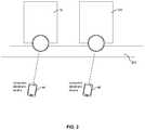
- FIG. 2shows that multiple devices 12 , 12 A may be controlled by respective CE devices 44 , 46 to interact on a surface 200 such as a flat planar surface.
- FIG. 3shows that the first device 12 may have a camera providing a field of view (FOV) with a FOV angle 300 .
- the first device 12may emit laser range-finding light such as IR light along one or more range finding axes 302 .
- the cameramay be implemented by a complementary metal oxide semiconductor (CMOS) camera that can detect both visible and infrared light so as to be able to produce still or video images along with detections of laser reflections for purposes of generating a depth map.
- CMOScomplementary metal oxide semiconductor
- the second device 12 Amay have a camera providing a field of view (FOV) with a FOV angle 304 .
- the first device 12may emit laser range-finding light such as IR light along one or more range finding axes 306 . More than two devices may be used. In the example shown, each device is within the FOV of the other device, and the FOVs of the devices overlap as shown.
- the devices 12 , 12 A emitting their respective laser beamsestablish an optical micro-mesh.
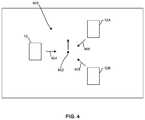
- FIG. 4illustrates a system 400 with three devices 12 , 12 A, 12 B implemented by any of the devices described herein.
- each devicegenerates its own depth map by imaging the other devices within its field of view.
- the depth mapsare aggregated together for a reference location that may be user-defined.
- the disclosure belowassumes a reference location 402 located centrally in the system 400 .
- Other reference locationsmay be modeled, including using one of the devices 12 , 12 A, 12 B as a reference location.
- the arrows 404 , 406 , 408respectively represent the centerline axis of the field of view of each device 12 , 12 A, 12 B.
- FIGS. 5-7respectively show depth maps 500 , 600 , 700 generated by each device 12 , 12 A, 12 B of the other devices in its FOV.
- Some of the imagesare larger than others because the device corresponding to the larger image is closer to the imaging device than the device corresponding to the smaller image.
- the depth mapscan be 3D depth maps as shown, and the relative locations of the devices are known to the other devices according to further description below.
- each depth mapincludes not only the images of the other devices but their relative locations with respect to the imaging device, which knows the direction its respective centerline axis is in and thus the angular offset of each image from that centerline axis.
- the absolute locations of the devicesmay be determined if desired using, e.g., the absolute location of any one of the devices using, for instance, its GPS location.
- Distance to each imaged devicemay be determined by correlating the size of its image to distance. For example, since the size of each device can be known and preprogrammed into each of the devices, a reference image size, e.g., height, can be correlated with a reference distance. Linear interpolation can be used to then associate smaller image sizes than the reference size with greater distances than the reference distance and larger image sizes than the reference size with lesser distances than the reference distance.
- a reference image sizee.g., height
- the depth maps 500 , 600 , 700are aggregated into a single aggregate depth map 800 referenced to the reference location 402 in FIG. 4 .
- the aspects of each image in the aggregate depth map 800are altered as appropriate for the angle and distance each device is from the reference location 402 . This may be done because each of the three devices in the example shown is present in two of the three depth maps, and presents a different aspect in each depth map the device appears in.
- One or more of the processors described hereincan execute a graphics engine to access the multiple aspects of each imaged device and present a single image of the device with the aspect it would present when viewed from the reference point 402 , as shown in the aggregated depth map 800 of FIG. 8 .
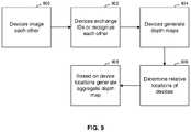
- FIG. 9illustrates further.
- the devices 12 , 12 A, 12 Bimage each other and at block 902 may exchange identifications or otherwise recognize each other using image recognition, so that each device can know the, e.g., the size of the other devices (based on ID) and the relative locations of the devices relative to the imaging device. Additionally, if desired one or more objects in the field of view of each camera can be used to help stitch the images together by referencing specific/common points.
- the devicescan exchange information such as image information or image recognition information derived from executing image recognition algorithms on the image to inform other devices of one or more non-CE device objects (such as, e.g., a pen, a projector, a chair, etc.) in the FOV of the device.
- non-CE device objectssuch as, e.g., a pen, a projector, a chair, etc.
- Each devicemay then compare the received information from other devices to determine if the same object(s) are in its FOV and in this way use commonly recognized objects as reference points in knowing what the FOV of the other device cameras is.
- the depth maps 500 - 700are generated by the respective devices by imaging reflections of the ranging laser light.
- the locations of the devicesare determined at block 906 using example principles above, and based on the device locations and the reference location for the aggregated depth map, the aggregated depth map 800 is generated as described above.
- FIG. 10illustrates.
- one of the 12 , 12 Ais used to generate a first image of others of the devices.
- the deviceis then physically moved to another location at block 1002 , still within line of sight of the objects in the first image, and a second image generated by the device at block 1004 .
- the first and second imagesare stitched together according to principles above. Note that while FIG. 10 shows only two images separated by a device movement step, it is to be understood that additional images may be taken with device movement between successive images to be stitched together.
- FIG. 11illustrates that for a given indoor usage environment, many objects expected to be the relevant field of view of a device during later encounters requiring depth maps according to principles above (such as plural devices 12 , 12 A, etc.) can be scanned in advance at block 1100 .
- the resulting imagesare stored at block 1102 .
- the stored imagemay be, among other examples, an image per se as well as a “representation” of a shape or only a portion of an image.
- the stored imagemay be as simple as a radiused corner of an object, so the system can fill in the pixels by looking at the actual image, and what a close representation may look like and fill in the missing pixels.
- the stored imagesare analyzed at block 1104 to, e.g., determine and record characteristics of objects in the images, such as the shapes and edges of objects in the image(s). These characteristics can be cataloged in data storage.
- the logicmay proceed to block 1108 to access the stored images and catalogued characteristics from blocks 1102 and 1104 .
- Image recognitionfor instance, may be employed at state 1110 to determine whether any of the stored images with their characteristics match, within a matching criteria, the current image generated at block 1106 . This matching is assisted because the edges and shapes of the objects in the stored images are known and hence this “known” information can be used to assist the depth map video processing.
- the logicmay, if desired, move to block 1112 to remove a portion of one or both images to render cropped images, in some embodiments showing only the object in the current image from block 1106 and the matching object from the stored image from block 1102 .
- the cropped imagesmay be digitally zoomed at block 1114 by, e.g., expanding the remaining image pixels to fill the original image area.
- the zoomed images(or, when cropping is not used, the full original current and stored image) may be combined at block 1116 by superimposing them on each other to render a modified zoomed image that has higher resolution than any of the images from which it is derived.
- the superimpositionmay be done using super-resolution principles such as those disclosed in any of the incorporated patents referenced herein.
- the modified zoomed imagemay then be presented on a display or otherwise used for, e.g., navigation of a mobile computing device 12 moving among other objects 12 A.
- motion estimation algorithmsmay be employed. For example, a simple algorithm might be to estimate motion using groups of pixels in each image that remain substantially unchanged in value except for their relative positions within the images, with motion vectors being derived directly from the motion of the groups of pixels from image to image.
- the super-imposition techniquesmay use Bayesian or Kalman filtering techniques in rendering the final, modified zoomed image.
- Present principlescan be used in an indoor setting. It may or may not be on a flat surface. Given the preceding conditions, GPS cannot feasibly be used to determine the individual camera locations. However, since the cameras can often see several other cameras in the system, each camera can be given a unique id number and a mechanism to identify either electronically, or visually, the cameras in the field of view of another camera, the relative locations of the cameras can be calculated.
Landscapes
- Engineering & Computer Science (AREA)
- Multimedia (AREA)
- Signal Processing (AREA)
- Physics & Mathematics (AREA)
- General Physics & Mathematics (AREA)
- Theoretical Computer Science (AREA)
- Processing Or Creating Images (AREA)
- Length Measuring Devices By Optical Means (AREA)
- User Interface Of Digital Computer (AREA)
Abstract
Description
Claims (18)
Priority Applications (2)
| Application Number | Priority Date | Filing Date | Title |
|---|---|---|---|
| US15/477,369US10979687B2 (en) | 2017-04-03 | 2017-04-03 | Using super imposition to render a 3D depth map |
| PCT/US2018/018697WO2018186937A1 (en) | 2017-04-03 | 2018-02-20 | Using super imposition to render a 3d depth map |
Applications Claiming Priority (1)
| Application Number | Priority Date | Filing Date | Title |
|---|---|---|---|
| US15/477,369US10979687B2 (en) | 2017-04-03 | 2017-04-03 | Using super imposition to render a 3D depth map |
Publications (2)
| Publication Number | Publication Date |
|---|---|
| US20180288385A1 US20180288385A1 (en) | 2018-10-04 |
| US10979687B2true US10979687B2 (en) | 2021-04-13 |
Family
ID=63670242
Family Applications (1)
| Application Number | Title | Priority Date | Filing Date |
|---|---|---|---|
| US15/477,369Active2038-07-23US10979687B2 (en) | 2017-04-03 | 2017-04-03 | Using super imposition to render a 3D depth map |
Country Status (2)
| Country | Link |
|---|---|
| US (1) | US10979687B2 (en) |
| WO (1) | WO2018186937A1 (en) |
Families Citing this family (3)
| Publication number | Priority date | Publication date | Assignee | Title |
|---|---|---|---|---|
| CN109643053B (en)* | 2018-11-24 | 2021-06-29 | 深圳阜时科技有限公司 | Projection device and its light source and equipment |
| CN110033483A (en)* | 2019-04-03 | 2019-07-19 | 北京清微智能科技有限公司 | Based on DCNN depth drawing generating method and system |
| CN112258618B (en)* | 2020-11-04 | 2021-05-14 | 中国科学院空天信息创新研究院 | Semantic mapping and positioning method based on fusion of prior laser point cloud and depth map |
Citations (130)
| Publication number | Priority date | Publication date | Assignee | Title |
|---|---|---|---|---|
| US5228069A (en) | 1989-06-04 | 1993-07-13 | Elscint Ltd. | Dual slice scanner |
| US6291816B1 (en) | 1999-06-08 | 2001-09-18 | Robotic Vision Systems, Inc. | System and method for measuring object features with coordinated two and three dimensional imaging |
| US6420698B1 (en) | 1997-04-24 | 2002-07-16 | Cyra Technologies, Inc. | Integrated system for quickly and accurately imaging and modeling three-dimensional objects |
| US6442465B2 (en) | 1992-05-05 | 2002-08-27 | Automotive Technologies International, Inc. | Vehicular component control systems and methods |
| US6664501B1 (en) | 2002-06-13 | 2003-12-16 | Igor Troitski | Method for creating laser-induced color images within three-dimensional transparent media |
| US20040141753A1 (en) | 2003-01-21 | 2004-07-22 | Lightpointe Communications, Inc. | Apparatus and method for tracking in free-space optical communication systems |
| US20040141170A1 (en) | 2003-01-21 | 2004-07-22 | Jamieson James R. | System for profiling objects on terrain forward and below an aircraft utilizing a cross-track laser altimeter |
| US20040208272A1 (en) | 2002-06-03 | 2004-10-21 | Moursund Carter M | Methods and systems for aligning and maintaining alignment of point-to-point transceivers in a network |
| US20050031166A1 (en) | 2003-05-29 | 2005-02-10 | Kikuo Fujimura | Visual tracking using depth data |
| US20050207755A1 (en) | 2004-03-19 | 2005-09-22 | Fujitsu Limited | Scheduling token-controlled data transmissions in communication networks |
| US20050226214A1 (en) | 2004-04-08 | 2005-10-13 | Isaac Keslassy | Scheduling with delayed graphs for communication networks |
| US6970183B1 (en) | 2000-06-14 | 2005-11-29 | E-Watch, Inc. | Multimedia surveillance and monitoring system including network configuration |
| US20060221241A1 (en) | 2005-03-29 | 2006-10-05 | Pioneer Corporation | Image-quality adjusting apparatus, image-quality adjusting method, and display apparatus |
| US20060239558A1 (en) | 2005-02-08 | 2006-10-26 | Canesta, Inc. | Method and system to segment depth images and to detect shapes in three-dimensionally acquired data |
| US20070024614A1 (en) | 2005-07-26 | 2007-02-01 | Tam Wa J | Generating a depth map from a two-dimensional source image for stereoscopic and multiview imaging |
| US7184088B1 (en) | 1998-10-28 | 2007-02-27 | Measurement Devices Limited | Apparatus and method for obtaining 3D images |
| US7262854B2 (en) | 2004-06-25 | 2007-08-28 | Konica Minolta Sensing, Inc. | Multi-angle colorimeter |
| US20070279415A1 (en) | 2006-06-01 | 2007-12-06 | Steve Sullivan | 2D to 3D image conversion |
| US20080152247A1 (en) | 2006-12-21 | 2008-06-26 | Byung Tae Oh | Methods and Systems for Image Noise Processing |
| US20090080885A1 (en) | 2005-05-27 | 2009-03-26 | Research Triangel Institute | Scheduling method and system for optical burst switched networks |
| US20090190853A1 (en) | 2006-08-11 | 2009-07-30 | Yo-Hwan Noh | Image noise reduction apparatus and method, recorded medium recorded the program performing it |
| US7752483B1 (en) | 2006-12-13 | 2010-07-06 | Science Applications International Corporation | Process and system for three-dimensional urban modeling |
| US7791009B2 (en) | 2007-11-27 | 2010-09-07 | University Of Washington | Eliminating illumination crosstalk while using multiple imaging devices with plural scanning devices, each coupled to an optical fiber |
| EP2225699A1 (en) | 2007-11-27 | 2010-09-08 | University of Washington | Eliminating illumination crosstalk while imaging using multiple imaging devices |
| US20100302365A1 (en) | 2009-05-29 | 2010-12-02 | Microsoft Corporation | Depth Image Noise Reduction |
| US20110025843A1 (en) | 2009-07-31 | 2011-02-03 | Mesa Imaging Ag | Time of Flight Camera with Rectangular Field of Illumination |
| US20110188773A1 (en) | 2010-02-04 | 2011-08-04 | Jianing Wei | Fast Depth Map Generation for 2D to 3D Conversion |
| US20110243570A1 (en) | 2010-03-31 | 2011-10-06 | Samsung Electronics Co., Ltd. | Method and apparatus for transmitting visibility frame according to setting of sleep mode in visible light communication system |
| US20120032833A1 (en) | 2010-08-09 | 2012-02-09 | Milligan Stephen D | Radar coherent processing interval scheduling via ad hoc network |
| US20120044476A1 (en) | 2008-05-09 | 2012-02-23 | Ball Aerospace & Technologies Corp. | Systems and methods of scene and action capture using imaging system incorporating 3d lidar |
| US20120056982A1 (en) | 2010-09-08 | 2012-03-08 | Microsoft Corporation | Depth camera based on structured light and stereo vision |
| US20120069009A1 (en)* | 2009-09-18 | 2012-03-22 | Kabushiki Kaisha Toshiba | Image processing apparatus |
| US20120168605A1 (en) | 2008-08-08 | 2012-07-05 | Mirrorcle Technologies, Inc. | Device for optical imaging, tracking, and position measurement with a scanning mems mirror |
| US20120182394A1 (en) | 2011-01-19 | 2012-07-19 | Samsung Electronics Co., Ltd. | 3d image signal processing method for removing pixel noise from depth information and 3d image signal processor therefor |
| US20120248514A1 (en) | 2011-03-31 | 2012-10-04 | Honda Motor Co., Ltd. | Solid-state image sensing device |
| US20120293615A1 (en) | 2011-05-17 | 2012-11-22 | National Taiwan University | Real-time depth-aware image enhancement system |
| US20120306876A1 (en) | 2011-06-06 | 2012-12-06 | Microsoft Corporation | Generating computer models of 3d objects |
| US20130051516A1 (en) | 2011-08-31 | 2013-02-28 | Carestream Health, Inc. | Noise suppression for low x-ray dose cone-beam image reconstruction |
| US20130129224A1 (en) | 2011-11-21 | 2013-05-23 | Microsoft Corporation | Combined depth filtering and super resolution |
| US20130195083A1 (en) | 2012-01-26 | 2013-08-01 | Young Soo Kim | Main hub, sub hub, and sensor node communicating in wireless body area network (wban) including at least one sub hub, and communication method thereof |
| US20130207970A1 (en) | 2012-02-15 | 2013-08-15 | Primesense Ltd. | Scanning depth engine |
| US20130278604A1 (en)* | 2008-06-30 | 2013-10-24 | Sony Electronics Inc. | Super-resolution digital zoom |
| US20130293684A1 (en) | 2011-04-15 | 2013-11-07 | Faro Technologies, Inc. | Three-dimensional coordinate scanner and method of operation |
| US20130329012A1 (en) | 2012-06-07 | 2013-12-12 | Liberty Reach Inc. | 3-d imaging and processing system including at least one 3-d or depth sensor which is continually calibrated during use |
| US20140058367A1 (en) | 2011-03-25 | 2014-02-27 | Board Of Trustees Of Michigan State University | Adaptive laser system for ophthalmic use |
| US20140079288A1 (en) | 2012-09-20 | 2014-03-20 | Samsung Electronics Co., Ltd. | Apparatus and method for processing color image using depth image |
| US20140092221A1 (en)* | 2012-09-28 | 2014-04-03 | JVC Kenwood Corporation | Image processing apparatus and method, and related computer program |
| EP2730939A2 (en) | 2012-11-09 | 2014-05-14 | Omron Corporation | Sensor system |
| US8730309B2 (en) | 2010-02-23 | 2014-05-20 | Microsoft Corporation | Projectors and depth cameras for deviceless augmented reality and interaction |
| US20140168424A1 (en) | 2011-07-21 | 2014-06-19 | Ziv Attar | Imaging device for motion detection of objects in a scene, and method for motion detection of objects in a scene |
| US8780113B1 (en) | 2012-08-21 | 2014-07-15 | Pelican Imaging Corporation | Systems and methods for performing depth estimation using image data from multiple spectral channels |
| US20140198977A1 (en) | 2012-03-21 | 2014-07-17 | Texas Instruments Incorporated | Enhancement of Stereo Depth Maps |
| US8803950B2 (en) | 2009-08-24 | 2014-08-12 | Samsung Electronics Co., Ltd. | Three-dimensional face capturing apparatus and method and computer-readable medium thereof |
| US20140226984A1 (en) | 2009-11-10 | 2014-08-14 | Calix, Inc. | Transparent clock for precision timing distribution |
| US20140240467A1 (en) | 2012-10-24 | 2014-08-28 | Lsi Corporation | Image processing method and apparatus for elimination of depth artifacts |
| US8824827B2 (en) | 2006-03-17 | 2014-09-02 | Qualcomm Incorporated | Systems, methods, and apparatus for exposure control |
| US8830555B2 (en) | 2006-11-09 | 2014-09-09 | International Business Machines Corporation | Device and system for reflective digital light processing (DLP) |
| US20140253679A1 (en) | 2011-06-24 | 2014-09-11 | Laurent Guigues | Depth measurement quality enhancement |
| US20140253691A1 (en)* | 2013-03-06 | 2014-09-11 | Leap Motion, Inc. | Motion-capture apparatus with light-source form factor |
| US20140293993A1 (en) | 2013-03-26 | 2014-10-02 | Sensity Systems, Inc. | Sensor nodes with multicast transmissions in lighting sensory network |
| US20140333728A1 (en) | 2011-02-10 | 2014-11-13 | Technische Universitat Munchen Forschungsforderung und Technologietransfer | Method of Enhanced Depth Image Acquisition |
| US20140355901A1 (en) | 2012-03-29 | 2014-12-04 | Nikon Corporation | Algorithm for minimizing latent sharp image cost function and point spread function cost function with a spatial mask in a regularization term |
| US20140376768A1 (en) | 2013-06-19 | 2014-12-25 | The Boeing Company | Systems and Methods for Tracking Location of Movable Target Object |
| US20140375851A1 (en) | 2013-06-19 | 2014-12-25 | Samsung Electronics Co., Ltd. | Image sensor, image processing system including the same, and method of operating the same |
| US20150002636A1 (en) | 2013-06-28 | 2015-01-01 | Cable Television Laboratories, Inc. | Capturing Full Motion Live Events Using Spatially Distributed Depth Sensing Cameras |
| US20150024336A1 (en)* | 2013-07-18 | 2015-01-22 | A.Tron3D Gmbh | Combining depth-maps from different acquisition methods |
| US20150022643A1 (en) | 2013-07-19 | 2015-01-22 | Google Inc. | Asymmetric Sensor Array for Capturing Images |
| US20150036926A1 (en) | 2011-11-29 | 2015-02-05 | Ouk Choi | Method and apparatus for converting depth image in high resolution |
| US20150070489A1 (en) | 2013-09-11 | 2015-03-12 | Microsoft Corporation | Optical modules for use with depth cameras |
| EP2339532B1 (en) | 2009-11-17 | 2015-04-08 | Vestel Elektronik Sanayi ve Ticaret A.S. | Depth compensated noise reduction in multi-view video |
| US9031356B2 (en) | 2012-03-20 | 2015-05-12 | Dolby Laboratories Licensing Corporation | Applying perceptually correct 3D film noise |
| US20150130904A1 (en) | 2013-11-12 | 2015-05-14 | Samsung Electronics Co., Ltd. | Depth Sensor and Method of Operating the Same |
| US20150130903A1 (en) | 2013-11-12 | 2015-05-14 | Microsoft Corporation | Power efficient laser diode driver circuit and method |
| US20150171968A1 (en) | 2013-12-18 | 2015-06-18 | John Featherston | Free space optical transceiver |
| US9098908B2 (en) | 2011-10-21 | 2015-08-04 | Microsoft Technology Licensing, Llc | Generating a depth map |
| US20150248765A1 (en) | 2014-02-28 | 2015-09-03 | Microsoft Corporation | Depth sensing using an rgb camera |
| US20150254811A1 (en) | 2014-03-07 | 2015-09-10 | Qualcomm Incorporated | Depth aware enhancement for stereo video |
| US20150294686A1 (en) | 2014-04-11 | 2015-10-15 | Youlapse Oy | Technique for gathering and combining digital images from multiple sources as video |
| US20150309663A1 (en) | 2014-04-28 | 2015-10-29 | Qualcomm Incorporated | Flexible air and surface multi-touch detection in mobile platform |
| US20150339471A1 (en) | 2014-05-23 | 2015-11-26 | Texas Instruments Incorporated | Device unlock with three dimensional (3d) captures |
| US9214492B2 (en) | 2012-01-10 | 2015-12-15 | Softkinetic Sensors N.V. | Multispectral sensor |
| US20150373322A1 (en)* | 2014-06-20 | 2015-12-24 | Qualcomm Incorporated | Automatic multiple depth cameras synchronization using time sharing |
| US20150371393A1 (en) | 2014-06-19 | 2015-12-24 | Qualcomm Incorporated | Structured light three-dimensional (3d) depth map based on content filtering |
| US20150378023A1 (en) | 2013-02-13 | 2015-12-31 | Universitat Politecnica De Catalunya | System and method for scanning a surface and computer program implementing the method |
| US9235928B2 (en) | 2012-01-24 | 2016-01-12 | University Of Southern California | 3D body modeling, from a single or multiple 3D cameras, in the presence of motion |
| US20160012633A1 (en) | 2014-07-09 | 2016-01-14 | Google Inc. | High-Quality Stereo Reconstruction Featuring Depth Map Alignment and Outlier Identification |
| US9262691B2 (en) | 2013-12-17 | 2016-02-16 | Catholic University Industry Academic Cooperation Foundation | Method for extracting salient object from stereoscopic image |
| US9275302B1 (en) | 2012-08-24 | 2016-03-01 | Amazon Technologies, Inc. | Object detection and identification |
| US9286694B2 (en) | 2014-01-10 | 2016-03-15 | Electronics And Telecommunications Research Institute | Apparatus and method for detecting multiple arms and hands by using three-dimensional image |
| US20160099777A1 (en) | 2014-10-01 | 2016-04-07 | Futurewei Technologies, Inc. | Optical Receiver with Optical Transmitter-Specific Dispersion Post-Compensation |
| US20160098847A1 (en) | 2014-10-01 | 2016-04-07 | Ora Inc. | Multidimensional halo-based visualization system |
| US20160097851A1 (en) | 2013-02-28 | 2016-04-07 | Identified Technologies Corporation | Ground Survey and Obstacle Detection System |
| US9319139B2 (en) | 2013-03-11 | 2016-04-19 | Futurewei Technologies, Inc. | Long distance multi-mode communication |
| US20160124089A1 (en) | 2014-10-31 | 2016-05-05 | Cedes Safety & Automation Ag | Absolute distance measurement for time-of-flight sensors |
| US20160173869A1 (en)* | 2014-12-15 | 2016-06-16 | Nokia Corporation | Multi-Camera System Consisting Of Variably Calibrated Cameras |
| US20160191759A1 (en) | 2014-12-29 | 2016-06-30 | Intel Corporation | Method and system of lens shift correction for a camera array |
| US9405008B2 (en) | 2013-05-17 | 2016-08-02 | Massachusetts Institute Of Technology | Methods and apparatus for multi-frequency camera |
| US20160239725A1 (en) | 2015-02-12 | 2016-08-18 | Mitsubishi Electric Research Laboratories, Inc. | Method for Denoising Time-of-Flight Range Images |
| US9426450B1 (en) | 2015-08-18 | 2016-08-23 | Intel Corporation | Depth sensing auto focus multiple camera system |
| US9435891B2 (en) | 2012-02-15 | 2016-09-06 | Heptagon Micro Optics Pte. Ltd. | Time of flight camera with stripe illumination |
| US20160291160A1 (en) | 2015-03-31 | 2016-10-06 | Faro Technologies, Inc. | Mobile three-dimensional measuring instrument |
| US9483835B2 (en) | 2014-05-09 | 2016-11-01 | Ricoh Company, Ltd. | Depth value restoration method and system |
| US20160328828A1 (en) | 2014-02-25 | 2016-11-10 | Graduate School At Shenzhen, Tsinghua University | Depth map super-resolution processing method |
| US20160344967A1 (en) | 2015-05-18 | 2016-11-24 | Analog Devices, Inc. | Interline charge-coupled devices |
| US9542749B2 (en) | 2014-01-06 | 2017-01-10 | Microsoft Technology Licensing, Llc | Fast general multipath correction in time-of-flight imaging |
| US9557166B2 (en) | 2014-10-21 | 2017-01-31 | Hand Held Products, Inc. | Dimensioning system with multipath interference mitigation |
| US20170061701A1 (en) | 2015-08-26 | 2017-03-02 | Adobe Systems Incorporated | Color-based depth smoothing of scanned 3d model to enhance geometry in 3d printing |
| US9618613B2 (en) | 2012-02-22 | 2017-04-11 | Hitachi Kokusai Electric Inc. | Radio communication apparatus, radio communication method, and radio communication system |
| US20170188017A1 (en) | 2015-12-23 | 2017-06-29 | Stmicroelectronics (Research & Development) Ltd. | Depth maps generated from a single sensor |
| US20170201738A1 (en) | 2015-06-13 | 2017-07-13 | Alberto Daniel Lacaze | Senising on uavs for mapping and obstacle avoidance |
| US9760837B1 (en) | 2016-03-13 | 2017-09-12 | Microsoft Technology Licensing, Llc | Depth from time-of-flight using machine learning |
| US20170264880A1 (en) | 2016-03-14 | 2017-09-14 | Symbol Technologies, Llc | Device and method of dimensioning using digital images and depth data |
| US20170277180A1 (en) | 2016-03-28 | 2017-09-28 | Baer Research Company | Unmanned surveyor |
| US20170332750A1 (en) | 2016-05-20 | 2017-11-23 | Shadecraft, LLC | Intelligent Shading System with Movable Base Assembly |
| US20170372527A1 (en)* | 2016-06-22 | 2017-12-28 | Aquifi, Inc. | Systems and methods for scanning three-dimensional objects |
| US20170374342A1 (en) | 2016-06-24 | 2017-12-28 | Isee, Inc. | Laser-enhanced visual simultaneous localization and mapping (slam) for mobile devices |
| US9860618B2 (en) | 2014-09-30 | 2018-01-02 | Futurewei Technologies, Inc. | Upstream wavelength calibration in optical networks |
| US20180033357A1 (en) | 2015-02-05 | 2018-02-01 | Appotronics China Corporation | Projection device, projection control system, and projection control method |
| US20180034579A1 (en) | 2016-07-26 | 2018-02-01 | Futurewei Technologies, Inc. | Burst-Mode Discrete Multi-Tone for Networks |
| US20180053284A1 (en) | 2016-08-22 | 2018-02-22 | Magic Leap, Inc. | Virtual, augmented, and mixed reality systems and methods |
| US20180100928A1 (en) | 2016-10-09 | 2018-04-12 | Innoviz Technologies Ltd. | Methods circuits devices assemblies systems and functionally associated machine executable code for active scene scanning |
| US20180124371A1 (en)* | 2016-10-31 | 2018-05-03 | Verizon Patent And Licensing Inc. | Methods and Systems for Generating Depth Data by Converging Independently-Captured Depth Maps |
| US9995578B2 (en) | 2012-11-27 | 2018-06-12 | Chenyang Ge | Image depth perception device |
| US20180173990A1 (en) | 2016-12-19 | 2018-06-21 | Sony Corporation | Using pattern recognition to reduce noise in a 3d map |
| US20180176483A1 (en) | 2014-12-29 | 2018-06-21 | Metaio Gmbh | Method and sytem for generating at least one image of a real environment |
| US20180190014A1 (en) | 2017-01-03 | 2018-07-05 | Honeywell International Inc. | Collaborative multi sensor system for site exploitation |
| US20180234617A1 (en) | 2017-02-15 | 2018-08-16 | John Przyborski | Motion camera autofocus systems |
| US10142612B2 (en) | 2014-02-13 | 2018-11-27 | Chenyang Ge | One method of binocular depth perception based on active structured light |
| US10559127B2 (en)* | 2015-09-25 | 2020-02-11 | Magic Leap, Inc. | Methods and systems for detecting and combining structural features in 3D reconstruction |
| US10650542B2 (en)* | 2017-03-31 | 2020-05-12 | Eys3D Microelectronics, Co. | Depth map generation device for merging multiple depth maps |
- 2017
- 2017-04-03USUS15/477,369patent/US10979687B2/enactiveActive
- 2018
- 2018-02-20WOPCT/US2018/018697patent/WO2018186937A1/ennot_activeCeased
Patent Citations (132)
| Publication number | Priority date | Publication date | Assignee | Title |
|---|---|---|---|---|
| US5228069A (en) | 1989-06-04 | 1993-07-13 | Elscint Ltd. | Dual slice scanner |
| US6442465B2 (en) | 1992-05-05 | 2002-08-27 | Automotive Technologies International, Inc. | Vehicular component control systems and methods |
| US6420698B1 (en) | 1997-04-24 | 2002-07-16 | Cyra Technologies, Inc. | Integrated system for quickly and accurately imaging and modeling three-dimensional objects |
| US7184088B1 (en) | 1998-10-28 | 2007-02-27 | Measurement Devices Limited | Apparatus and method for obtaining 3D images |
| US6291816B1 (en) | 1999-06-08 | 2001-09-18 | Robotic Vision Systems, Inc. | System and method for measuring object features with coordinated two and three dimensional imaging |
| US6970183B1 (en) | 2000-06-14 | 2005-11-29 | E-Watch, Inc. | Multimedia surveillance and monitoring system including network configuration |
| US20040208272A1 (en) | 2002-06-03 | 2004-10-21 | Moursund Carter M | Methods and systems for aligning and maintaining alignment of point-to-point transceivers in a network |
| US6664501B1 (en) | 2002-06-13 | 2003-12-16 | Igor Troitski | Method for creating laser-induced color images within three-dimensional transparent media |
| US20040141170A1 (en) | 2003-01-21 | 2004-07-22 | Jamieson James R. | System for profiling objects on terrain forward and below an aircraft utilizing a cross-track laser altimeter |
| US20040141753A1 (en) | 2003-01-21 | 2004-07-22 | Lightpointe Communications, Inc. | Apparatus and method for tracking in free-space optical communication systems |
| US20050031166A1 (en) | 2003-05-29 | 2005-02-10 | Kikuo Fujimura | Visual tracking using depth data |
| US20050207755A1 (en) | 2004-03-19 | 2005-09-22 | Fujitsu Limited | Scheduling token-controlled data transmissions in communication networks |
| US20050226214A1 (en) | 2004-04-08 | 2005-10-13 | Isaac Keslassy | Scheduling with delayed graphs for communication networks |
| US7262854B2 (en) | 2004-06-25 | 2007-08-28 | Konica Minolta Sensing, Inc. | Multi-angle colorimeter |
| US20060239558A1 (en) | 2005-02-08 | 2006-10-26 | Canesta, Inc. | Method and system to segment depth images and to detect shapes in three-dimensionally acquired data |
| US20060221241A1 (en) | 2005-03-29 | 2006-10-05 | Pioneer Corporation | Image-quality adjusting apparatus, image-quality adjusting method, and display apparatus |
| US20090080885A1 (en) | 2005-05-27 | 2009-03-26 | Research Triangel Institute | Scheduling method and system for optical burst switched networks |
| US20070024614A1 (en) | 2005-07-26 | 2007-02-01 | Tam Wa J | Generating a depth map from a two-dimensional source image for stereoscopic and multiview imaging |
| US8824827B2 (en) | 2006-03-17 | 2014-09-02 | Qualcomm Incorporated | Systems, methods, and apparatus for exposure control |
| US20070279415A1 (en) | 2006-06-01 | 2007-12-06 | Steve Sullivan | 2D to 3D image conversion |
| US20090190853A1 (en) | 2006-08-11 | 2009-07-30 | Yo-Hwan Noh | Image noise reduction apparatus and method, recorded medium recorded the program performing it |
| US8830555B2 (en) | 2006-11-09 | 2014-09-09 | International Business Machines Corporation | Device and system for reflective digital light processing (DLP) |
| US7752483B1 (en) | 2006-12-13 | 2010-07-06 | Science Applications International Corporation | Process and system for three-dimensional urban modeling |
| US20080152247A1 (en) | 2006-12-21 | 2008-06-26 | Byung Tae Oh | Methods and Systems for Image Noise Processing |
| US7791009B2 (en) | 2007-11-27 | 2010-09-07 | University Of Washington | Eliminating illumination crosstalk while using multiple imaging devices with plural scanning devices, each coupled to an optical fiber |
| EP2225699A1 (en) | 2007-11-27 | 2010-09-08 | University of Washington | Eliminating illumination crosstalk while imaging using multiple imaging devices |
| US20120044476A1 (en) | 2008-05-09 | 2012-02-23 | Ball Aerospace & Technologies Corp. | Systems and methods of scene and action capture using imaging system incorporating 3d lidar |
| US20130278604A1 (en)* | 2008-06-30 | 2013-10-24 | Sony Electronics Inc. | Super-resolution digital zoom |
| US20120168605A1 (en) | 2008-08-08 | 2012-07-05 | Mirrorcle Technologies, Inc. | Device for optical imaging, tracking, and position measurement with a scanning mems mirror |
| US20100302365A1 (en) | 2009-05-29 | 2010-12-02 | Microsoft Corporation | Depth Image Noise Reduction |
| US20110025843A1 (en) | 2009-07-31 | 2011-02-03 | Mesa Imaging Ag | Time of Flight Camera with Rectangular Field of Illumination |
| US8803950B2 (en) | 2009-08-24 | 2014-08-12 | Samsung Electronics Co., Ltd. | Three-dimensional face capturing apparatus and method and computer-readable medium thereof |
| US20120069009A1 (en)* | 2009-09-18 | 2012-03-22 | Kabushiki Kaisha Toshiba | Image processing apparatus |
| US20140226984A1 (en) | 2009-11-10 | 2014-08-14 | Calix, Inc. | Transparent clock for precision timing distribution |
| EP2339532B1 (en) | 2009-11-17 | 2015-04-08 | Vestel Elektronik Sanayi ve Ticaret A.S. | Depth compensated noise reduction in multi-view video |
| US20110188773A1 (en) | 2010-02-04 | 2011-08-04 | Jianing Wei | Fast Depth Map Generation for 2D to 3D Conversion |
| US8730309B2 (en) | 2010-02-23 | 2014-05-20 | Microsoft Corporation | Projectors and depth cameras for deviceless augmented reality and interaction |
| US20110243570A1 (en) | 2010-03-31 | 2011-10-06 | Samsung Electronics Co., Ltd. | Method and apparatus for transmitting visibility frame according to setting of sleep mode in visible light communication system |
| US20120032833A1 (en) | 2010-08-09 | 2012-02-09 | Milligan Stephen D | Radar coherent processing interval scheduling via ad hoc network |
| US20120056982A1 (en) | 2010-09-08 | 2012-03-08 | Microsoft Corporation | Depth camera based on structured light and stereo vision |
| US20120182394A1 (en) | 2011-01-19 | 2012-07-19 | Samsung Electronics Co., Ltd. | 3d image signal processing method for removing pixel noise from depth information and 3d image signal processor therefor |
| US20140333728A1 (en) | 2011-02-10 | 2014-11-13 | Technische Universitat Munchen Forschungsforderung und Technologietransfer | Method of Enhanced Depth Image Acquisition |
| US20140058367A1 (en) | 2011-03-25 | 2014-02-27 | Board Of Trustees Of Michigan State University | Adaptive laser system for ophthalmic use |
| US20120248514A1 (en) | 2011-03-31 | 2012-10-04 | Honda Motor Co., Ltd. | Solid-state image sensing device |
| US20130293684A1 (en) | 2011-04-15 | 2013-11-07 | Faro Technologies, Inc. | Three-dimensional coordinate scanner and method of operation |
| US20120293615A1 (en) | 2011-05-17 | 2012-11-22 | National Taiwan University | Real-time depth-aware image enhancement system |
| US20120306876A1 (en) | 2011-06-06 | 2012-12-06 | Microsoft Corporation | Generating computer models of 3d objects |
| US20140253679A1 (en) | 2011-06-24 | 2014-09-11 | Laurent Guigues | Depth measurement quality enhancement |
| US20140168424A1 (en) | 2011-07-21 | 2014-06-19 | Ziv Attar | Imaging device for motion detection of objects in a scene, and method for motion detection of objects in a scene |
| US20130051516A1 (en) | 2011-08-31 | 2013-02-28 | Carestream Health, Inc. | Noise suppression for low x-ray dose cone-beam image reconstruction |
| US9098908B2 (en) | 2011-10-21 | 2015-08-04 | Microsoft Technology Licensing, Llc | Generating a depth map |
| US20130129224A1 (en) | 2011-11-21 | 2013-05-23 | Microsoft Corporation | Combined depth filtering and super resolution |
| US20150036926A1 (en) | 2011-11-29 | 2015-02-05 | Ouk Choi | Method and apparatus for converting depth image in high resolution |
| US9214492B2 (en) | 2012-01-10 | 2015-12-15 | Softkinetic Sensors N.V. | Multispectral sensor |
| US9235928B2 (en) | 2012-01-24 | 2016-01-12 | University Of Southern California | 3D body modeling, from a single or multiple 3D cameras, in the presence of motion |
| US20130195083A1 (en) | 2012-01-26 | 2013-08-01 | Young Soo Kim | Main hub, sub hub, and sensor node communicating in wireless body area network (wban) including at least one sub hub, and communication method thereof |
| US20130207970A1 (en) | 2012-02-15 | 2013-08-15 | Primesense Ltd. | Scanning depth engine |
| US9435891B2 (en) | 2012-02-15 | 2016-09-06 | Heptagon Micro Optics Pte. Ltd. | Time of flight camera with stripe illumination |
| US9618613B2 (en) | 2012-02-22 | 2017-04-11 | Hitachi Kokusai Electric Inc. | Radio communication apparatus, radio communication method, and radio communication system |
| US9031356B2 (en) | 2012-03-20 | 2015-05-12 | Dolby Laboratories Licensing Corporation | Applying perceptually correct 3D film noise |
| US20140198977A1 (en) | 2012-03-21 | 2014-07-17 | Texas Instruments Incorporated | Enhancement of Stereo Depth Maps |
| US20140355901A1 (en) | 2012-03-29 | 2014-12-04 | Nikon Corporation | Algorithm for minimizing latent sharp image cost function and point spread function cost function with a spatial mask in a regularization term |
| US20130329012A1 (en) | 2012-06-07 | 2013-12-12 | Liberty Reach Inc. | 3-d imaging and processing system including at least one 3-d or depth sensor which is continually calibrated during use |
| US9858673B2 (en) | 2012-08-21 | 2018-01-02 | Fotonation Cayman Limited | Systems and methods for estimating depth and visibility from a reference viewpoint for pixels in a set of images captured from different viewpoints |
| US8780113B1 (en) | 2012-08-21 | 2014-07-15 | Pelican Imaging Corporation | Systems and methods for performing depth estimation using image data from multiple spectral channels |
| US9275302B1 (en) | 2012-08-24 | 2016-03-01 | Amazon Technologies, Inc. | Object detection and identification |
| US20140079288A1 (en) | 2012-09-20 | 2014-03-20 | Samsung Electronics Co., Ltd. | Apparatus and method for processing color image using depth image |
| US20140092221A1 (en)* | 2012-09-28 | 2014-04-03 | JVC Kenwood Corporation | Image processing apparatus and method, and related computer program |
| US20140240467A1 (en) | 2012-10-24 | 2014-08-28 | Lsi Corporation | Image processing method and apparatus for elimination of depth artifacts |
| EP2730939A2 (en) | 2012-11-09 | 2014-05-14 | Omron Corporation | Sensor system |
| US9995578B2 (en) | 2012-11-27 | 2018-06-12 | Chenyang Ge | Image depth perception device |
| US20150378023A1 (en) | 2013-02-13 | 2015-12-31 | Universitat Politecnica De Catalunya | System and method for scanning a surface and computer program implementing the method |
| US20160097851A1 (en) | 2013-02-28 | 2016-04-07 | Identified Technologies Corporation | Ground Survey and Obstacle Detection System |
| US20140253691A1 (en)* | 2013-03-06 | 2014-09-11 | Leap Motion, Inc. | Motion-capture apparatus with light-source form factor |
| US9319139B2 (en) | 2013-03-11 | 2016-04-19 | Futurewei Technologies, Inc. | Long distance multi-mode communication |
| US20140293993A1 (en) | 2013-03-26 | 2014-10-02 | Sensity Systems, Inc. | Sensor nodes with multicast transmissions in lighting sensory network |
| US9405008B2 (en) | 2013-05-17 | 2016-08-02 | Massachusetts Institute Of Technology | Methods and apparatus for multi-frequency camera |
| US20140375851A1 (en) | 2013-06-19 | 2014-12-25 | Samsung Electronics Co., Ltd. | Image sensor, image processing system including the same, and method of operating the same |
| US20140376768A1 (en) | 2013-06-19 | 2014-12-25 | The Boeing Company | Systems and Methods for Tracking Location of Movable Target Object |
| US20150002636A1 (en) | 2013-06-28 | 2015-01-01 | Cable Television Laboratories, Inc. | Capturing Full Motion Live Events Using Spatially Distributed Depth Sensing Cameras |
| US20150024336A1 (en)* | 2013-07-18 | 2015-01-22 | A.Tron3D Gmbh | Combining depth-maps from different acquisition methods |
| US20150022643A1 (en) | 2013-07-19 | 2015-01-22 | Google Inc. | Asymmetric Sensor Array for Capturing Images |
| US20150070489A1 (en) | 2013-09-11 | 2015-03-12 | Microsoft Corporation | Optical modules for use with depth cameras |
| US20150130904A1 (en) | 2013-11-12 | 2015-05-14 | Samsung Electronics Co., Ltd. | Depth Sensor and Method of Operating the Same |
| US20150130903A1 (en) | 2013-11-12 | 2015-05-14 | Microsoft Corporation | Power efficient laser diode driver circuit and method |
| US9262691B2 (en) | 2013-12-17 | 2016-02-16 | Catholic University Industry Academic Cooperation Foundation | Method for extracting salient object from stereoscopic image |
| US20150171968A1 (en) | 2013-12-18 | 2015-06-18 | John Featherston | Free space optical transceiver |
| US9542749B2 (en) | 2014-01-06 | 2017-01-10 | Microsoft Technology Licensing, Llc | Fast general multipath correction in time-of-flight imaging |
| US9286694B2 (en) | 2014-01-10 | 2016-03-15 | Electronics And Telecommunications Research Institute | Apparatus and method for detecting multiple arms and hands by using three-dimensional image |
| US10142612B2 (en) | 2014-02-13 | 2018-11-27 | Chenyang Ge | One method of binocular depth perception based on active structured light |
| US20160328828A1 (en) | 2014-02-25 | 2016-11-10 | Graduate School At Shenzhen, Tsinghua University | Depth map super-resolution processing method |
| US20150248765A1 (en) | 2014-02-28 | 2015-09-03 | Microsoft Corporation | Depth sensing using an rgb camera |
| US20150254811A1 (en) | 2014-03-07 | 2015-09-10 | Qualcomm Incorporated | Depth aware enhancement for stereo video |
| US20150294686A1 (en) | 2014-04-11 | 2015-10-15 | Youlapse Oy | Technique for gathering and combining digital images from multiple sources as video |
| US20150309663A1 (en) | 2014-04-28 | 2015-10-29 | Qualcomm Incorporated | Flexible air and surface multi-touch detection in mobile platform |
| US9483835B2 (en) | 2014-05-09 | 2016-11-01 | Ricoh Company, Ltd. | Depth value restoration method and system |
| US20150339471A1 (en) | 2014-05-23 | 2015-11-26 | Texas Instruments Incorporated | Device unlock with three dimensional (3d) captures |
| US20150371393A1 (en) | 2014-06-19 | 2015-12-24 | Qualcomm Incorporated | Structured light three-dimensional (3d) depth map based on content filtering |
| US20150373322A1 (en)* | 2014-06-20 | 2015-12-24 | Qualcomm Incorporated | Automatic multiple depth cameras synchronization using time sharing |
| US20160012633A1 (en) | 2014-07-09 | 2016-01-14 | Google Inc. | High-Quality Stereo Reconstruction Featuring Depth Map Alignment and Outlier Identification |
| US9860618B2 (en) | 2014-09-30 | 2018-01-02 | Futurewei Technologies, Inc. | Upstream wavelength calibration in optical networks |
| US20160098847A1 (en) | 2014-10-01 | 2016-04-07 | Ora Inc. | Multidimensional halo-based visualization system |
| US9806813B2 (en) | 2014-10-01 | 2017-10-31 | Futurewei Technologies, Inc. | Optical receiver with optical transmitter-specific dispersion post-compensation |
| US20160099777A1 (en) | 2014-10-01 | 2016-04-07 | Futurewei Technologies, Inc. | Optical Receiver with Optical Transmitter-Specific Dispersion Post-Compensation |
| US9557166B2 (en) | 2014-10-21 | 2017-01-31 | Hand Held Products, Inc. | Dimensioning system with multipath interference mitigation |
| US20160124089A1 (en) | 2014-10-31 | 2016-05-05 | Cedes Safety & Automation Ag | Absolute distance measurement for time-of-flight sensors |
| US20160173869A1 (en)* | 2014-12-15 | 2016-06-16 | Nokia Corporation | Multi-Camera System Consisting Of Variably Calibrated Cameras |
| US20160191759A1 (en) | 2014-12-29 | 2016-06-30 | Intel Corporation | Method and system of lens shift correction for a camera array |
| US20180176483A1 (en) | 2014-12-29 | 2018-06-21 | Metaio Gmbh | Method and sytem for generating at least one image of a real environment |
| US20180033357A1 (en) | 2015-02-05 | 2018-02-01 | Appotronics China Corporation | Projection device, projection control system, and projection control method |
| US20160239725A1 (en) | 2015-02-12 | 2016-08-18 | Mitsubishi Electric Research Laboratories, Inc. | Method for Denoising Time-of-Flight Range Images |
| US20160291160A1 (en) | 2015-03-31 | 2016-10-06 | Faro Technologies, Inc. | Mobile three-dimensional measuring instrument |
| US20160344967A1 (en) | 2015-05-18 | 2016-11-24 | Analog Devices, Inc. | Interline charge-coupled devices |
| US20170201738A1 (en) | 2015-06-13 | 2017-07-13 | Alberto Daniel Lacaze | Senising on uavs for mapping and obstacle avoidance |
| US9426450B1 (en) | 2015-08-18 | 2016-08-23 | Intel Corporation | Depth sensing auto focus multiple camera system |
| US20170061701A1 (en) | 2015-08-26 | 2017-03-02 | Adobe Systems Incorporated | Color-based depth smoothing of scanned 3d model to enhance geometry in 3d printing |
| US10559127B2 (en)* | 2015-09-25 | 2020-02-11 | Magic Leap, Inc. | Methods and systems for detecting and combining structural features in 3D reconstruction |
| US20170188017A1 (en) | 2015-12-23 | 2017-06-29 | Stmicroelectronics (Research & Development) Ltd. | Depth maps generated from a single sensor |
| US9760837B1 (en) | 2016-03-13 | 2017-09-12 | Microsoft Technology Licensing, Llc | Depth from time-of-flight using machine learning |
| US20170264880A1 (en) | 2016-03-14 | 2017-09-14 | Symbol Technologies, Llc | Device and method of dimensioning using digital images and depth data |
| US20170277180A1 (en) | 2016-03-28 | 2017-09-28 | Baer Research Company | Unmanned surveyor |
| US20170332750A1 (en) | 2016-05-20 | 2017-11-23 | Shadecraft, LLC | Intelligent Shading System with Movable Base Assembly |
| US20170372527A1 (en)* | 2016-06-22 | 2017-12-28 | Aquifi, Inc. | Systems and methods for scanning three-dimensional objects |
| US20170374342A1 (en) | 2016-06-24 | 2017-12-28 | Isee, Inc. | Laser-enhanced visual simultaneous localization and mapping (slam) for mobile devices |
| US20180034579A1 (en) | 2016-07-26 | 2018-02-01 | Futurewei Technologies, Inc. | Burst-Mode Discrete Multi-Tone for Networks |
| US20180053284A1 (en) | 2016-08-22 | 2018-02-22 | Magic Leap, Inc. | Virtual, augmented, and mixed reality systems and methods |
| US20180100928A1 (en) | 2016-10-09 | 2018-04-12 | Innoviz Technologies Ltd. | Methods circuits devices assemblies systems and functionally associated machine executable code for active scene scanning |
| US20180124371A1 (en)* | 2016-10-31 | 2018-05-03 | Verizon Patent And Licensing Inc. | Methods and Systems for Generating Depth Data by Converging Independently-Captured Depth Maps |
| US20180173990A1 (en) | 2016-12-19 | 2018-06-21 | Sony Corporation | Using pattern recognition to reduce noise in a 3d map |
| US20180190014A1 (en) | 2017-01-03 | 2018-07-05 | Honeywell International Inc. | Collaborative multi sensor system for site exploitation |
| US20180234617A1 (en) | 2017-02-15 | 2018-08-16 | John Przyborski | Motion camera autofocus systems |
| US10650542B2 (en)* | 2017-03-31 | 2020-05-12 | Eys3D Microelectronics, Co. | Depth map generation device for merging multiple depth maps |
Non-Patent Citations (55)
| Title |
|---|
| Daniel Freedman, Eyal Krupka, Yoni Smolin, Ido Leichter, Mirko Schmidt, "SRA: Fast Removal of General Multipath for ToF Sensors", Microsoft Research, Microsoft Corporation, Mar. 24, 2014. |
| Derek Chan, Hylke Buisman, Christian Theobalt, Sebastian Thrun, "A Noise-Aware Filter for Real-Time Depth Upsampling", Oct. 5, 2008, retrieved from https://hal.inria.fr/inria-00326784. |
| He et al, "Iterative Transduction Learning for Automatic Image Segmentation and Matting with RGB-D Data", Elsevier, Mar. 2014. |
| Ho, Edmond S.L. et al., "Improving Posture Classification Accuracy for Depth Sensor-Based Human Activity Monitoring in Smart Environments", Jul. 2016, retrieved from http://www.sciencedirect.com/science/article/pii/S1077314216000138. |
| Jang et al, "Depth Map Generation Using a Single Image Sensor with Phase Masks", Chang-Ang University, Seoul, South Korea, Jun. 2016. |
| Jinbeum Jang, Sangwoo Park, Jieun Jo, Joonki Paik, "Depth map generation using a single image sensor with phase masks", Image Processing and Intelligent System Laboratory Graduate School of Advanced Imaging Science and Film, Chung-Ang University, Seoul, South Korea, Optical Society of America, 2016. |
| Kim et al, "Multi-focusing and Depth Estimation Using a Color Shift Model-Based Computational Camera", IEEE Transactions on Image Processing, vol. 21, No. 9, Sep. 2012. |
| Li et al, "Brain-Inspired Framework for Fusion of Multiple Depth Cues", IEEE Transactions on Circuits and Systems for Video Technology, vol. 23, No. 7, Jul. 2013. |
| Michael Taylor, Glenn Black, Javier Fernandez Rico, "Multipoint Slam Capture", file history of related U.S. Appl. No. 16/019,140, filed Jun. 26, 2018. |
| Nathan Silberman, Rob Fergus, "Indoor Scene Segmentation using a Structured Light Sensor", Dept. of Computer Science, Nov. 6, 2011, Courant Institute, New York University, pp. 601-608. |
| Peter Shintani, Jose Omar Gonzalez Hernandez, William Clay, Pablo Antonio Espinosa, Fred Andfield, Bibhudendu Mohapatra, Keith Resch, Morio Usami, file history of related U.S. Appl. No. 15/371,433, filed Dec. 7, 2016. |
| Peter Shintani, Jose Omar Gonzalez Hernandez, William Clay, Pablo Antonio Espinosa, Fred Ansfield, Bibhudendu Mohapatra, Keith Resch, Morio Usami, "Color Noise Reduction in 3D Depth Map", related U.S. Appl. No. 15/371,433, Applicant's response to Final Office Action filed Apr. 15, 2019. |
| Peter Shintani, Jose Omar Gonzalez Hernandez, William Clay, Pablo Antonio Espinosa, Fred Ansfield, Bibhudendu Mohapatra, Keith Resch, Morio Usami, "Color Noise Reduction in 3D Depth Map", related U.S. Appl. No. 15/371,433, Applicant's response to Non-Final Office Action filed Jan. 17, 2019. |
| Peter Shintani, Jose Omar Gonzalez Hernandez, William Clay, Pablo Antonio Espinosa, Fred Ansfield, Bibhudendu Mohapatra, Keith Resch, Morio Usami, "Color Noise Reduction in 3D Depth Map", related U.S. Appl. No. 15/371,433, Final Office Action dated Apr. 2, 2019. |
| Peter Shintani, Jose Omar Gonzalez Hernandez, William Clay, Pablo Antonio Espinosa, Fred Ansfield, Bibhudendu Mohapatra, Keith Resch, Morio Usami, "Color Noise Reduction in 3D Depth Map", related U.S. Appl. No. 15/371,433, Non-Final Office Action dated Jan. 10, 2019. |
| Peter Shintani, Jose Omar Gonzalez Hernandez, William Clay, Pablo Antonio Espinosa, Fred Ansfield, Bibhudendu Mohapatra, Keith Resch, Morio Usami, "Optical Micromesh for Computerized Devices", related U.S. Appl. No. 15/370,197, Applicant's response to Final Office Action filed Sep. 12, 2018. |
| Peter Shintani, Jose Omar Gonzalez Hernandez, William Clay, Pablo Antonio Espinosa, Fred Ansfield, Bibhudendu Mohapatra, Keith Resch, Morio Usami, "Optical Micromesh for Computerized Devices", related U.S. Appl. No. 15/370,197, Applicant's response to Non-Final Office Action filed Apr. 1, 2019. |
| Peter Shintani, Jose Omar Gonzalez Hernandez, William Clay, Pablo Antonio Espinosa, Fred Ansfield, Bibhudendu Mohapatra, Keith Resch, Morio Usami, "Optical Micromesh for Computerized Devices", related U.S. Appl. No. 15/370,197, Applicant's response to Non-Final Office Action filed Apr. 16, 2018. |
| Peter Shintani, Jose Omar Gonzalez Hernandez, William Clay, Pablo Antonio Espinosa, Fred Ansfield, Bibhudendu Mohapatra, Keith Resch, Morio Usami, "Optical Micromesh for Computerized Devices", related U.S. Appl. No. 15/370,197, Final Office Action dated Sep. 10, 2018. |
| Peter Shintani, Jose Omar Gonzalez Hernandez, William Clay, Pablo Antonio Espinosa, Fred Ansfield, Bibhudendu Mohapatra, Keith Resch, Morio Usami, "Optical Micromesh for Computerized Devices", related U.S. Appl. No. 15/370,197, Non-Final Office Action dated Apr. 5, 2018. |
| Peter Shintani, Jose Omar Gonzalez Hernandez, William Clay, Pablo Antonio Espinosa, Fred Ansfield, Bibhudendu Mohapatra, Keith Resch, Morio Usami, "Optical Micromesh for Computerized Devices", related U.S. Appl. No. 15/370,197, Non-Final Office Action dated Mar. 21, 2019. |
| Peter Shintani, Jose Omar Gonzalez Hernandez, William Clay, Pablo Antonio Espinosa, Fred Ansfield, Bibhudendu Mohapatra, Keith Resch, Morio Usami, "Using Micro Mirrors to Improve the Field of View of a 3D Depth Map", related U.S. Appl. No. 15/432,674, Applicant's response to Non-Final Office Action filed Feb. 20, 2019. |
| Peter Shintani, Jose Omar Gonzalez Hernandez, William Clay, Pablo Antonio Espinosa, Fred Ansfield, Bibhudendu Mohapatra, Keith Resch, Morio Usami, "Using Micro Mirrors to Improve the Field of View of a 3D Depth Map", related U.S. Appl. No. 15/432,674, Non-Final Office Action dated Feb. 14, 2019. |
| Peter Shintani, Jose Omar Gonzalez Hernandez, William Clay, Pablo Antonio Espinosa, Fred Ansfield, Bibhudendu Mohapatra, Keith Resch, Morio Usami, "Using Multiple Cameras to Stitch a Consolidated 3D Depth Map", related U.S. Appl. No. 15/383,683, Applicants response to Non-Final Office Action filed Jul. 16, 2018. |
| Peter Shintani, Jose Omar Gonzalez Hernandez, William Clay, Pablo Antonio Espinosa, Fred Ansfield, Bibhudendu Mohapatra, Keith Resch, Morio Usami, "Using Multiple Cameras to Stitch a Consolidated 3D Depth Map", related U.S. Appl. No. 15/383,683, Non-Final Office Action dated Jul. 12, 2018. |
| Peter Shintani, Jose Omar Gonzalez Hernandez, William Clay, Pablo Antonio Espinosa, Fred Ansfield, Bibhudendu Mohapatra, Keith Resch, Morio Usami, "Using Pattern Recognition to Reduce Noise in a 3D Map", related U.S. Appl. No. 15/383,392, Applicant's response to Non-Final Office Action filed Apr. 25, 2018. |
| Peter Shintani, Jose Omar Gonzalez Hernandez, William Clay, Pablo Antonio Espinosa, Fred Ansfield, Bibhudendu Mohapatra, Keith Resch, Morio Usami, "Using Pattern Recognition to Reduce Noise in a 3D Map", related U.S. Appl. No. 15/383,392, Final Office Action dated Sep. 12, 2018. |
| Peter Shintani, Jose Omar Gonzalez Hernandez, William Clay, Pablo Antonio Espinosa, Fred Ansfield, Bibhudendu Mohapatra, Keith Resch, Morio Usami, "Using Pattern Recognition to Reduce Noise in a 3D Map", related U.S. Appl. No. 15/383,392, Non-Final Office Action dated Apr. 19, 2018. |
| Peter Shintani, Jose Omar Gonzalez Hernandez, William Clay, Pablo Antonio Espinosa, Fred Ansfield, Bibhudendu Mohapatra, Keith Resch, Morio Usami, file history of related U.S. Appl. No. 15/370,197, filed Dec. 6, 2016. |
| Peter Shintani, Jose Omar Gonzalez Hernandez, William Clay, Pablo Antonio Espinosa, Fred Ansfield, Bibhudendu Mohapatra, Keith Resch, Morio Usami, file history of related U.S. Appl. No. 15/383,392, filed Dec. 19, 2016. |
| Peter Shintani, Jose Omar Gonzalez Hernandez, William Clay, Pablo Antonio Espinosa, Fred Ansfield, Bibhudendu Mohapatra, Keith Resch, Morio Usami, file history of related U.S. Appl. No. 15/383,683, filed Dec. 19, 2016. |
| Peter Shintani, Jose Omar Gonzalez Hernandez, William Clay, Pablo Antonio Espinosa, Fred Ansfield, Bibhudendu Mohapatra, Keith Resch, Morio Usami, file history of related U.S. Appl. No. 15/432,674, filed Feb. 14, 2017. |
| Peter Shintani, Jose Omar Gonzalez Hernandez, William Clay, Pablo Antonio Espinosa, Fred Ansfield, Bibhudendu Mohaptra, Keith Resch, Morio Usami, "Using Pattern Recognition to Reduce Noise in a 3D Map", related U.S. Appl. No. 15/383,392, Applicant's response to Final Office Action filed Sep. 14, 2015. |
| Peter Shintani, Morio Usami, Kazuyuki Shikama, Keith Resch, "Generating 3D Depth Map Using Parallax", file history of related U.S. Appl. No. 15/798,914, filed Oct. 31, 2017. |
| Peter Shintani, Morio Usami, Kissei Matsumoto, Kazuyuki Shikama, Bibhudendu Mohapatra, Keith Resch, "3D Depth Map", file history of related U.S. Appl. No. 15/590,497, filed May 9, 2017. |
| Peter Shintani, Morio Usami, Kissei Matsumoto, Kazuyuki Shikama, Bibhudendu Mohapatra, Keith Resch, "3D Depth Map", related U.S. Appl. No. 15/590,497, Applicant's response to Final Office Action filed Dec. 6, 2018. |
| Peter Shintani, Morio Usami, Kissei Matsumoto, Kazuyuki Shikama, Bibhudendu Mohapatra, Keith Resch, "3D Depth Map", related U.S. Appl. No. 15/590,497, Applicant's response to Non-Final Office Action filed Apr. 2, 2019. |
| Peter Shintani, Morio Usami, Kissei Matsumoto, Kazuyuki Shikama, Bibhudendu Mohapatra, Keith Resch, "3D Depth Map", related U.S. Appl. No. 15/590,497, Applicant's response to Non-Final Office Action filed Jun. 20, 2018. |
| Peter Shintani, Morio Usami, Kissei Matsumoto, Kazuyuki Shikama, Bibhudendu Mohapatra, Keith Resch, "3D Depth Map", related U.S. Appl. No. 15/590,497, Final Office Action dated Nov. 19, 2018. |
| Peter Shintani, Morio Usami, Kissei Matsumoto, Kazuyuki Shikama, Bibhudendu Mohapatra, Keith Resch, "3D Depth Map", related U.S. Appl. No. 15/590,497, Non-Final Office Action dated Jun. 15, 2018. |
| Peter Shintani, Morio Usami, Kissei Matsumoto, Kazuyuki Shikama, Bibhudendu Mohapatra, Keith Resch, "3D Depth Map", related U.S. Appl. No. 15/590,497, Non-Final Office Action dated Mar. 25, 2019. |
| Quang H. Nguyen, Minh N. Do, Sanjay J. Patel, "Depth image-based rendering from multiple cameras with 3D propagation algorithm", May 27, 2009. |
| Riegler et al., "A Deep Primal-Dual Network for Guided Depth Super-Resolution", Institute for Computer Graphics and Vision, Graz University of TechnologyAustria, Jul. 28, 2016. |
| Roy et al, "Denoising 3D Models with Attributes Using Soft Thresholding", Bourgogne University, France, 2004. |
| Schuon et al., "High-Quality Scanning Using Time-of-Flight Depth Superresolution", Stanford University, 2008. |
| Shintani et al, "Color Noise Reduction in 3D Depth Map", related U.S. Appl. No. 15/371,433, Non-Final Office Action dated Jun. 21, 2019. |
| Shintani et al, "Color Noise Reduction in 3D Depth Map", related U.S. Appl. No. 15/371,433, Non-Final Office Action response filed Jun. 28, 2019. |
| Shintani et al, "Using Micro Mirrors to Improve the Field of View of a 3D Depth Map", related U.S. Appl. No. 15/432,674, Applicant's response to Final Office Action filed May 31, 2019. |
| Shintani et al, "Using Micro Mirrors to Improve the Field of View of a 3D Depth Map", related U.S. Appl. No. 15/432,674, Final Office Action dated May 3, 2019. |
| Shintani et al., "3D Depth Map", related U.S. Appl. No. 15/590,497, Applicant's response to Non-Final Office Action filed Aug. 7, 2019. |
| Shintani et al., "3D Depth Map", related U.S. Appl. No. 15/590,497, Non-Final Office Action dated Jul. 29, 2019. |
| Shintani et al., "Generating 3D Depth Map Using Parallax", related U.S. Appl. No. 15/798,914, Applicant's response to Non-Final Office Action filed Jul. 12, 2019. |
| Shintani et al., "Generating 3D Depth Map Using Parallax", related U.S. Appl. No. 15/798,914, Non-Final Office Action dated Jul. 9, 2019. |
| Shuran Song, Jianxiong Xiao, "Sliding Shapes for 3D Object Detection in Depth Images", Abstract, Sep. 2014. |
| Yo-Sung Ho, Yun-Suk Kang, "Multi-View Depth Generation using Multi-Depth Camera System", Gwangju Institute of Science and Technology, Jan. 4, 2016. |
Also Published As
| Publication number | Publication date |
|---|---|
| US20180288385A1 (en) | 2018-10-04 |
| WO2018186937A1 (en) | 2018-10-11 |
Similar Documents
| Publication | Publication Date | Title |
|---|---|---|
| US10979695B2 (en) | Generating 3D depth map using parallax | |
| US10795022B2 (en) | 3D depth map | |
| US9667862B2 (en) | Method, system, and computer program product for gamifying the process of obtaining panoramic images | |
| US9661214B2 (en) | Depth determination using camera focus | |
| US11590416B2 (en) | Multipoint SLAM capture | |
| US10181089B2 (en) | Using pattern recognition to reduce noise in a 3D map | |
| US10178370B2 (en) | Using multiple cameras to stitch a consolidated 3D depth map | |
| US10979687B2 (en) | Using super imposition to render a 3D depth map | |
| US10536684B2 (en) | Color noise reduction in 3D depth map | |
| JP2010128799A (en) | Composite media synthesizing apparatus, composite media display system, composite media synthesizing method, and composite media synthesizing program | |
| US12222420B2 (en) | Performance of a time of flight (ToF) laser range finding system using acoustic-based direction of arrival (DoA) | |
| US8648916B2 (en) | Control of an image capturing device | |
| US20220030206A1 (en) | Information processing apparatus, information processing method, program, and projection system | |
| US20240316461A1 (en) | Using laser to align a virtual environment in a game engine | |
| US10451714B2 (en) | Optical micromesh for computerized devices | |
| US10495735B2 (en) | Using micro mirrors to improve the field of view of a 3D depth map | |
| US10698109B2 (en) | Using direction of arrival with unique audio signature for object location detection | |
| WO2019037517A1 (en) | Mobile electronic device and method for processing task in task area | |
| WO2023179369A1 (en) | Positioning method and apparatus for control apparatus, and device, storage medium and computer program product |
Legal Events
| Date | Code | Title | Description |
|---|---|---|---|
| AS | Assignment | Owner name:SONY CORPORATION, JAPAN Free format text:ASSIGNMENT OF ASSIGNORS INTEREST;ASSIGNORS:SHINTANI, PETER;GONZALEZ HERNANDEZ, JOSE OMAR;CLAY, WILLIAM;AND OTHERS;SIGNING DATES FROM 20170405 TO 20170417;REEL/FRAME:042040/0957 | |
| AS | Assignment | Owner name:SONY INTERACTIVE ENTERTAINMENT INC., JAPAN Free format text:CORRECTIVE ASSIGNMENT TO CORRECT THE ASSIGNEE(S) TO BE SONY CORPORATION AND SONY INTERACTIVE ENTERTAINMENT INC. PREVIOUSLY RECORDED ON REEL 042040 FRAME 0957. ASSIGNOR(S) HEREBY CONFIRMS THE ASSIGNMENT;ASSIGNORS:SHINTANI, PETER;GONZALEZ HERNANDEZ, JOSE OMAR;CLAY, WILLIAM;AND OTHERS;SIGNING DATES FROM 20170405 TO 20170417;REEL/FRAME:042550/0808 Owner name:SONY CORPORATION, JAPAN Free format text:CORRECTIVE ASSIGNMENT TO CORRECT THE ASSIGNEE(S) TO BE SONY CORPORATION AND SONY INTERACTIVE ENTERTAINMENT INC. PREVIOUSLY RECORDED ON REEL 042040 FRAME 0957. ASSIGNOR(S) HEREBY CONFIRMS THE ASSIGNMENT;ASSIGNORS:SHINTANI, PETER;GONZALEZ HERNANDEZ, JOSE OMAR;CLAY, WILLIAM;AND OTHERS;SIGNING DATES FROM 20170405 TO 20170417;REEL/FRAME:042550/0808 | |
| STCV | Information on status: appeal procedure | Free format text:APPEAL BRIEF (OR SUPPLEMENTAL BRIEF) ENTERED AND FORWARDED TO EXAMINER | |
| STCV | Information on status: appeal procedure | Free format text:ON APPEAL -- AWAITING DECISION BY THE BOARD OF APPEALS | |
| STCV | Information on status: appeal procedure | Free format text:BOARD OF APPEALS DECISION RENDERED | |
| STPP | Information on status: patent application and granting procedure in general | Free format text:AMENDMENT / ARGUMENT AFTER BOARD OF APPEALS DECISION | |
| STPP | Information on status: patent application and granting procedure in general | Free format text:NOTICE OF ALLOWANCE MAILED -- APPLICATION RECEIVED IN OFFICE OF PUBLICATIONS | |
| STPP | Information on status: patent application and granting procedure in general | Free format text:PUBLICATIONS -- ISSUE FEE PAYMENT VERIFIED | |
| STCF | Information on status: patent grant | Free format text:PATENTED CASE | |
| MAFP | Maintenance fee payment | Free format text:PAYMENT OF MAINTENANCE FEE, 4TH YEAR, LARGE ENTITY (ORIGINAL EVENT CODE: M1551); ENTITY STATUS OF PATENT OWNER: LARGE ENTITY Year of fee payment:4 |